ts 136 211 - v14.2.0 - lte; evolved universal terrestrial ... · etsi 3gpp ts 36.211 version 14.2.0...
TRANSCRIPT
ETSI TS 136 211 V14.2.0 (2017-04)
LTE; Evolved Universal Terrestrial Radio Access (E-UTRA);
Physical channels and modulation (3GPP TS 36.211 version 14.2.0 Release 14)
TECHNICAL SPECIFICATION
ETSI
ETSI TS 136 211 V14.2.0 (2017-04)13GPP TS 36.211 version 14.2.0 Release 14
Reference RTS/TSGR-0136211ve20
Keywords LTE
ETSI
650 Route des Lucioles F-06921 Sophia Antipolis Cedex - FRANCE
Tel.: +33 4 92 94 42 00 Fax: +33 4 93 65 47 16
Siret N° 348 623 562 00017 - NAF 742 C
Association à but non lucratif enregistrée à la Sous-Préfecture de Grasse (06) N° 7803/88
Important notice
The present document can be downloaded from: http://www.etsi.org/standards-search
The present document may be made available in electronic versions and/or in print. The content of any electronic and/or print versions of the present document shall not be modified without the prior written authorization of ETSI. In case of any
existing or perceived difference in contents between such versions and/or in print, the only prevailing document is the print of the Portable Document Format (PDF) version kept on a specific network drive within ETSI Secretariat.
Users of the present document should be aware that the document may be subject to revision or change of status. Information on the current status of this and other ETSI documents is available at
https://portal.etsi.org/TB/ETSIDeliverableStatus.aspx
If you find errors in the present document, please send your comment to one of the following services: https://portal.etsi.org/People/CommiteeSupportStaff.aspx
Copyright Notification
No part may be reproduced or utilized in any form or by any means, electronic or mechanical, including photocopying and microfilm except as authorized by written permission of ETSI.
The content of the PDF version shall not be modified without the written authorization of ETSI. The copyright and the foregoing restriction extend to reproduction in all media.
© European Telecommunications Standards Institute 2017.
All rights reserved.
DECTTM, PLUGTESTSTM, UMTSTM and the ETSI logo are Trade Marks of ETSI registered for the benefit of its Members. 3GPPTM and LTE™ are Trade Marks of ETSI registered for the benefit of its Members and
of the 3GPP Organizational Partners. oneM2M logo is protected for the benefit of its Members
GSM® and the GSM logo are Trade Marks registered and owned by the GSM Association.

ETSI
ETSI TS 136 211 V14.2.0 (2017-04)23GPP TS 36.211 version 14.2.0 Release 14
Intellectual Property Rights IPRs essential or potentially essential to the present document may have been declared to ETSI. The information pertaining to these essential IPRs, if any, is publicly available for ETSI members and non-members, and can be found in ETSI SR 000 314: "Intellectual Property Rights (IPRs); Essential, or potentially Essential, IPRs notified to ETSI in respect of ETSI standards", which is available from the ETSI Secretariat. Latest updates are available on the ETSI Web server (https://ipr.etsi.org/).
Pursuant to the ETSI IPR Policy, no investigation, including IPR searches, has been carried out by ETSI. No guarantee can be given as to the existence of other IPRs not referenced in ETSI SR 000 314 (or the updates on the ETSI Web server) which are, or may be, or may become, essential to the present document.
Foreword This Technical Specification (TS) has been produced by the ETSI 3rd Generation Partnership Project (3GPP).
The present document may refer to technical specifications or reports using their 3GPP identities, UMTS identities or GSM identities. These should be interpreted as being references to the corresponding ETSI deliverables.
The cross reference between GSM, UMTS, 3GPP and ETSI identities can be found under http://webapp.etsi.org/key/queryform.asp.
Modal verbs terminology In the present document "shall", "shall not", "should", "should not", "may", "need not", "will", "will not", "can" and "cannot" are to be interpreted as described in clause 3.2 of the ETSI Drafting Rules (Verbal forms for the expression of provisions).
"must" and "must not" are NOT allowed in ETSI deliverables except when used in direct citation.

ETSI
ETSI TS 136 211 V14.2.0 (2017-04)33GPP TS 36.211 version 14.2.0 Release 14
Contents
Intellectual Property Rights ................................................................................................................................ 2
Foreword ............................................................................................................................................................. 2
Modal verbs terminology .................................................................................................................................... 2
Foreword ............................................................................................................................................................. 8
1 Scope ........................................................................................................................................................ 9
2 References ................................................................................................................................................ 9
3 Symbols and abbreviations ....................................................................................................................... 9
3.1 Symbols .............................................................................................................................................................. 9
3.2 Abbreviations ................................................................................................................................................... 13
4 Frame structure ....................................................................................................................................... 14
4.1 Frame structure type 1 ...................................................................................................................................... 14
4.2 Frame structure type 2 ...................................................................................................................................... 16
4.3 Frame structure type 3 ...................................................................................................................................... 17
5 Uplink ..................................................................................................................................................... 19
5.1 Overview .......................................................................................................................................................... 19
5.1.1 Physical channels ........................................................................................................................................ 19
5.1.2 Physical signals ........................................................................................................................................... 19
5.2 Slot structure and physical resources................................................................................................................ 19
5.2.1 Resource grid .............................................................................................................................................. 19
5.2.2 Resource elements ...................................................................................................................................... 21
5.2.3 Resource blocks .......................................................................................................................................... 21
5.2.4 Narrowbands and widebands ...................................................................................................................... 21
5.2.5 Guard period for narrowband and wideband retuning ................................................................................ 22
5.3 Physical uplink shared channel ........................................................................................................................ 24
5.3.1 Scrambling .................................................................................................................................................. 24
5.3.2 Modulation .................................................................................................................................................. 25
5.3.2A Layer mapping ............................................................................................................................................ 26
5.3.2A.1 Layer mapping for transmission on a single antenna port ..................................................................... 26
5.3.2A.2 Layer mapping for spatial multiplexing ................................................................................................ 26
5.3.3 Transform precoding................................................................................................................................... 27
5.3.3A Precoding .................................................................................................................................................... 27
5.3.3A.1 Precoding for transmission on a single antenna port ............................................................................. 27
5.3.3A.2 Precoding for spatial multiplexing ........................................................................................................ 27
5.3.4 Mapping to physical resources.................................................................................................................... 30
5.4 Physical uplink control channel ........................................................................................................................ 33
5.4.1 PUCCH formats 1, 1a and 1b ..................................................................................................................... 34
5.4.2 PUCCH formats 2, 2a and 2b ..................................................................................................................... 37
5.4.2A PUCCH format 3 ........................................................................................................................................ 38
5.4.2B PUCCH format 4 ........................................................................................................................................ 40
5.4.2C PUCCH format 5 ........................................................................................................................................ 40
5.4.3 Mapping to physical resources.................................................................................................................... 41
5.5 Reference signals .............................................................................................................................................. 44
5.5.1 Generation of the reference signal sequence ............................................................................................... 44
5.5.1.1 Base sequences of length RBsc3N or larger ............................................................................................ 44
5.5.1.2 Base sequences of length less than RBsc3N ............................................................................................ 45
5.5.1.3 Group hopping ...................................................................................................................................... 49
5.5.1.4 Sequence hopping ................................................................................................................................. 50
5.5.1.5 Determining virtual cell identity for sequence generation .................................................................... 50
5.5.2 Demodulation reference signal ................................................................................................................... 51
5.5.2.1 Demodulation reference signal for PUSCH .......................................................................................... 51
5.5.2.1.1 Reference signal sequence ............................................................................................................... 51
5.5.2.1.2 Mapping to physical resources ........................................................................................................ 53
5.5.2.2 Demodulation reference signal for PUCCH .......................................................................................... 54
5.5.2.2.1 Reference signal sequence ............................................................................................................... 54

ETSI
ETSI TS 136 211 V14.2.0 (2017-04)43GPP TS 36.211 version 14.2.0 Release 14
5.5.2.2.2 Mapping to physical resources ........................................................................................................ 56
5.5.3 Sounding reference signal ........................................................................................................................... 57
5.5.3.1 Sequence generation.............................................................................................................................. 57
5.5.3.2 Mapping to physical resources .............................................................................................................. 57
5.5.3.3 Sounding reference signal subframe configuration ............................................................................... 60
5.6 SC-FDMA baseband signal generation ............................................................................................................ 61
5.7 Physical random access channel ....................................................................................................................... 62
5.7.1 Time and frequency structure ..................................................................................................................... 62
5.7.2 Preamble sequence generation .................................................................................................................... 69
5.7.3 Baseband signal generation......................................................................................................................... 74
5.8 Modulation and upconversion .......................................................................................................................... 75
6 Downlink ................................................................................................................................................ 76
6.1 Overview .......................................................................................................................................................... 76
6.1.1 Physical channels ........................................................................................................................................ 76
6.1.2 Physical signals ........................................................................................................................................... 76
6.2 Slot structure and physical resource elements .................................................................................................. 77
6.2.1 Resource grid .............................................................................................................................................. 77
6.2.2 Resource elements ...................................................................................................................................... 78
6.2.3 Resource blocks .......................................................................................................................................... 79
6.2.3.1 Virtual resource blocks of localized type .............................................................................................. 79
6.2.3.2 Virtual resource blocks of distributed type ........................................................................................... 79
6.2.4 Resource-element groups ............................................................................................................................ 81
6.2.4A Enhanced Resource-Element Groups (EREGs) .......................................................................................... 81
6.2.5 Guard period for half-duplex FDD operation ............................................................................................. 82
6.2.6 Guard Period for TDD Operation ............................................................................................................... 82
6.2.7 Narrowbands and widebands ...................................................................................................................... 82
6.2.8 Guard period for narrowband and wideband retuning ................................................................................ 83
6.3 General structure for downlink physical channels ............................................................................................ 83
6.3.1 Scrambling .................................................................................................................................................. 84
6.3.2 Modulation .................................................................................................................................................. 85
6.3.3 Layer mapping ............................................................................................................................................ 85
6.3.3.1 Layer mapping for transmission on a single antenna port ..................................................................... 85
6.3.3.2 Layer mapping for spatial multiplexing ................................................................................................ 86
6.3.3.3 Layer mapping for transmit diversity .................................................................................................... 87
6.3.4 Precoding .................................................................................................................................................... 87
6.3.4.1 Precoding for transmission on a single antenna port ............................................................................. 87
6.3.4.2 Precoding for spatial multiplexing using antenna ports with cell-specific reference signals ................ 87
6.3.4.2.1 Precoding without CDD .................................................................................................................. 88
6.3.4.2.2 Precoding for large delay CDD ....................................................................................................... 88
6.3.4.2.3 Codebook for precoding and CSI reporting ..................................................................................... 89
6.3.4.3 Precoding for transmit diversity ............................................................................................................ 90
6.3.4.4 Precoding for spatial multiplexing using antenna ports with UE-specific reference signals................. 91
6.3.5 Mapping to resource elements .................................................................................................................... 92
6.4 Physical downlink shared channel .................................................................................................................... 92
6.4.1 Physical downlink shared channel for BL/CE UEs .................................................................................... 94
6.5 Physical multicast channel ............................................................................................................................... 96
6.6 Physical broadcast channel ............................................................................................................................... 96
6.6.1 Scrambling .................................................................................................................................................. 96
6.6.2 Modulation .................................................................................................................................................. 97
6.6.3 Layer mapping and precoding .................................................................................................................... 97
6.6.4 Mapping to resource elements .................................................................................................................... 97
6.7 Physical control format indicator channel ........................................................................................................ 98
6.7.1 Scrambling .................................................................................................................................................. 99
6.7.2 Modulation .................................................................................................................................................. 99
6.7.3 Layer mapping and precoding .................................................................................................................... 99
6.7.4 Mapping to resource elements .................................................................................................................. 100
6.8 Physical downlink control channel ................................................................................................................. 100
6.8.1 PDCCH formats ........................................................................................................................................ 100
6.8.2 PDCCH multiplexing and scrambling ...................................................................................................... 100
6.8.3 Modulation ................................................................................................................................................ 101
6.8.4 Layer mapping and precoding .................................................................................................................. 101

ETSI
ETSI TS 136 211 V14.2.0 (2017-04)53GPP TS 36.211 version 14.2.0 Release 14
6.8.5 Mapping to resource elements .................................................................................................................. 101
6.8A Enhanced physical downlink control channel ................................................................................................ 102
6.8A.1 EPDCCH formats ..................................................................................................................................... 102
6.8A.2 Scrambling ................................................................................................................................................ 104
6.8A.3 Modulation ................................................................................................................................................ 104
6.8A.4 Layer mapping and precoding .................................................................................................................. 104
6.8A.5 Mapping to resource elements .................................................................................................................. 104
6.8B MTC physical downlink control channel ....................................................................................................... 105
6.8B.1 MPDCCH formats .................................................................................................................................... 105
6.8B.2 Scrambling ................................................................................................................................................ 106
6.8B.3 Modulation ................................................................................................................................................ 107
6.8B.4 Layer mapping and precoding .................................................................................................................. 107
6.8B.5 Mapping to resource elements .................................................................................................................. 107
6.9 Physical hybrid ARQ indicator channel ......................................................................................................... 109
6.9.1 Modulation ................................................................................................................................................ 110
6.9.2 Resource group alignment, layer mapping and precoding ........................................................................ 111
6.9.3 Mapping to resource elements .................................................................................................................. 112
6.10 Reference signals ............................................................................................................................................ 114
6.10.1 Cell-specific Reference Signal (CRS)....................................................................................................... 114
6.10.1.1 Sequence generation............................................................................................................................ 115
6.10.1.2 Mapping to resource elements............................................................................................................. 115
6.10.2 MBSFN reference signals ......................................................................................................................... 117
6.10.2.1 Sequence generation............................................................................................................................ 117
6.10.2.1.1 Sequence generation for 15 kHz and 7.5 kHz subcarrier spacing ................................................. 117
6.10.2.1.2 Sequence generation for 1.25 kHz subcarrier spacing ................................................................... 117
6.10.2.2 Mapping to resource elements............................................................................................................. 118
6.10.2.2.1 Mapping to resource elements for 15 kHz and 7.5 kHz subcarrier spacing .................................. 118
6.10.2.2.1 Mapping to resource elements for 1.25 kHz .................................................................................. 120
6.10.3 UE-specific reference signals associated with PDSCH ............................................................................ 120
6.10.3.1 Sequence generation............................................................................................................................ 120
6.10.3.2 Mapping to resource elements............................................................................................................. 121
6.10.3A Demodulation reference signals associated with EPDCCH or MPDCCH ................................................ 126
6.10.3A.1 Sequence generation............................................................................................................................ 126
6.10.3A.2 Mapping to resource elements............................................................................................................. 127
6.10.4 Positioning reference signals .................................................................................................................... 129
6.10.4.1 Sequence generation............................................................................................................................ 129
6.10.4.2 Mapping to resource elements............................................................................................................. 129
6.10.4.3 Positioning reference signal subframe configuration .......................................................................... 132
6.10.5 CSI reference signals ................................................................................................................................ 132
6.10.5.1 Sequence generation............................................................................................................................ 133
6.10.5.2 Mapping to resource elements............................................................................................................. 133
6.10.5.3 CSI reference signal subframe configuration ...................................................................................... 142
6.11 Synchronization signals .................................................................................................................................. 142
6.11.1 Primary synchronization signal (PSS) ...................................................................................................... 142
6.11.1.1 Sequence generation............................................................................................................................ 142
6.11.1.2 Mapping to resource elements............................................................................................................. 143
6.11.2 Secondary synchronization signal (SSS) .................................................................................................. 144
6.11.2.1 Sequence generation............................................................................................................................ 144
6.11.2.2 Mapping to resource elements............................................................................................................. 145
6.11A Discovery signal ............................................................................................................................................. 146
6.12 OFDM baseband signal generation ................................................................................................................ 147
6.13 Modulation and upconversion ........................................................................................................................ 147
7 Generic functions ................................................................................................................................. 149
7.1 Modulation mapper ........................................................................................................................................ 149
7.1.1 BPSK ........................................................................................................................................................ 149
7.1.2 QPSK ........................................................................................................................................................ 149
7.1.3 16QAM ..................................................................................................................................................... 149
7.1.4 64QAM ..................................................................................................................................................... 150
7.1.5 256QAM ................................................................................................................................................... 152
7.2 Pseudo-random sequence generation.............................................................................................................. 154
8 Timing .................................................................................................................................................. 154
ETSI
ETSI TS 136 211 V14.2.0 (2017-04)63GPP TS 36.211 version 14.2.0 Release 14
8.1 Uplink-downlink frame timing ....................................................................................................................... 154
9 Sidelink................................................................................................................................................. 155
9.1 Overview ........................................................................................................................................................ 155
9.1.1 Physical channels ...................................................................................................................................... 155
9.1.2 Physical signals ......................................................................................................................................... 155
9.1.3 Handling of simultaneous sidelink and uplink/downlink transmissions ................................................... 155
9.2 Slot structure and physical resources.............................................................................................................. 156
9.2.1 Resource grid ............................................................................................................................................ 156
9.2.2 Resource elements .................................................................................................................................... 156
9.2.3 Resource blocks ........................................................................................................................................ 157
9.2.4 Resource pool ........................................................................................................................................... 157
9.2.5 Guard period ............................................................................................................................................. 157
9.3 Physical Sidelink Shared Channel .................................................................................................................. 157
9.3.1 Scrambling ................................................................................................................................................ 157
9.3.2 Modulation ................................................................................................................................................ 158
9.3.3 Layer mapping .......................................................................................................................................... 158
9.3.4 Transform precoding................................................................................................................................. 158
9.3.5 Precoding .................................................................................................................................................. 158
9.3.6 Mapping to physical resources.................................................................................................................. 158
9.4 Physical Sidelink Control Channel ................................................................................................................. 159
9.4.1 Scrambling ................................................................................................................................................ 159
9.4.2 Modulation ................................................................................................................................................ 159
9.4.3 Layer mapping .......................................................................................................................................... 159
9.4.4 Transform precoding................................................................................................................................. 159
9.4.5 Precoding .................................................................................................................................................. 159
9.4.6 Mapping to physical resources.................................................................................................................. 159
9.5 Physical Sidelink Discovery Channel............................................................................................................. 160
9.5.1 Scrambling ................................................................................................................................................ 160
9.5.2 Modulation ................................................................................................................................................ 160
9.5.3 Layer mapping .......................................................................................................................................... 160
9.5.4 Transform precoding................................................................................................................................. 160
9.5.5 Precoding .................................................................................................................................................. 160
9.5.6 Mapping to physical resources.................................................................................................................. 160
9.6 Physical Sidelink Broadcast Channel ............................................................................................................. 161
9.6.1 Scrambling ................................................................................................................................................ 161
9.6.2 Modulation ................................................................................................................................................ 161
9.6.3 Layer mapping .......................................................................................................................................... 161
9.6.4 Transform precoding................................................................................................................................. 161
9.6.5 Precoding .................................................................................................................................................. 161
9.6.6 Mapping to physical resources.................................................................................................................. 161
9.7 Sidelink Synchronization Signals ................................................................................................................... 161
9.7.1 Primary sidelink synchronization signal ................................................................................................... 162
9.7.1.1 Sequence generation............................................................................................................................ 162
9.7.1.2 Mapping to resource elements............................................................................................................. 162
9.7.2 Secondary sidelink synchronization signal ............................................................................................... 162
9.7.2.1 Sequence generation............................................................................................................................ 162
9.7.2.2 Mapping to resource elements............................................................................................................. 162
9.8 Demodulation reference signals ..................................................................................................................... 162
9.9 SC-FDMA baseband signal generation .......................................................................................................... 164
9.10 Timing ............................................................................................................................................................ 164
10 Narrowband IoT ................................................................................................................................... 165
10.1 Uplink ............................................................................................................................................................. 165
10.1.1 Overview .................................................................................................................................................. 165
10.1.1.1 Physical channels ................................................................................................................................ 165
10.1.1.2 Physical signals ................................................................................................................................... 165
10.1.2 Slot structure and physical resources ........................................................................................................ 166
10.1.2.1 Resource grid ...................................................................................................................................... 166
10.1.2.2 Resource elements ............................................................................................................................... 166
10.1.2.3 Resource unit....................................................................................................................................... 167
10.1.3 Narrowband physical uplink shared channel ............................................................................................ 167
10.1.3.1 Scrambling .......................................................................................................................................... 167

ETSI
ETSI TS 136 211 V14.2.0 (2017-04)73GPP TS 36.211 version 14.2.0 Release 14
10.1.3.2 Modulation .......................................................................................................................................... 167
10.1.3.3 Layer mapping .................................................................................................................................... 167
10.1.3.4 Transform precoding ........................................................................................................................... 167
10.1.3.5 Precoding ............................................................................................................................................ 168
10.1.3.6 Mapping to physical resources ............................................................................................................ 168
10.1.4 Demodulation reference signal ................................................................................................................. 168
10.1.4.1 Reference signal sequence .................................................................................................................. 168
10.1.4.1.1 Reference signal sequence for 1RUsc =N ....................................................................................... 168
10.1.4.1.2 Reference signal sequence for 1RUsc >N ........................................................................................ 169
10.1.4.1.3 Group hopping ............................................................................................................................... 171
10.1.4.2 Mapping to physical resources ............................................................................................................ 171
10.1.5 SC-FDMA baseband signal generation..................................................................................................... 172
10.1.6 Narrowband physical random access channel........................................................................................... 173
10.1.6.1 Time and frequency structure .............................................................................................................. 173
10.1.6.2 Baseband signal generation ................................................................................................................. 174
10.1.7 Modulation and upconversion................................................................................................................... 174
10.2 Downlink ........................................................................................................................................................ 175
10.2.1 Overview .................................................................................................................................................. 175
10.2.1.1 Physical channels ................................................................................................................................ 175
10.2.1.2 Physical signals ................................................................................................................................... 175
10.2.2 Slot structure and physical resource elements .......................................................................................... 175
10.2.2.1 Resource grid ...................................................................................................................................... 175
10.2.2.2 Resource elements ............................................................................................................................... 175
10.2.2.3 Guard period for half-duplex FDD operation ...................................................................................... 175
10.2.3 Narrowband physical downlink shared channel ....................................................................................... 176
10.2.3.1 Scrambling .......................................................................................................................................... 176
10.2.3.2 Modulation .......................................................................................................................................... 176
10.2.3.3 Layer mapping and precoding ............................................................................................................. 176
10.2.3.4 Mapping to resource elements............................................................................................................. 176
10.2.4 Narrowband physical broadcast channel................................................................................................... 177
10.2.4.1 Scrambling .......................................................................................................................................... 177
10.2.4.2 Modulation .......................................................................................................................................... 177
10.2.4.3 Layer mapping and precoding ............................................................................................................. 177
10.2.4.4 Mapping to resource elements............................................................................................................. 177
10.2.5 Narrowband physical downlink control channel....................................................................................... 178
10.2.5.1 NPDCCH formats ............................................................................................................................... 178
10.2.5.2 Scrambling .......................................................................................................................................... 178
10.2.5.3 Modulation .......................................................................................................................................... 178
10.2.5.4 Layer mapping and precoding ............................................................................................................. 178
10.2.5.5 Mapping to resource elements............................................................................................................. 178
10.2.6 Narrowband reference signal (NRS) ......................................................................................................... 179
10.2.6.1 Sequence generation............................................................................................................................ 181
10.2.6.2 Mapping to resource elements............................................................................................................. 181
10.2.6A Narrowband positioning reference signal (NPRS) .................................................................................... 182
10.2.6A.1 Sequence generation............................................................................................................................ 182
10.2.6A.2 Mapping to resource elements............................................................................................................. 183
10.2.6A.3 NPRS subframe configuration ............................................................................................................ 184
10.2.7 Synchronization signals ............................................................................................................................ 185
10.2.7.1 Narrowband primary synchronization signal (NPSS) ......................................................................... 185
10.2.7.1.1 Sequence generation ...................................................................................................................... 185
10.2.7.1.2 Mapping to resource elements ....................................................................................................... 185
10.2.7.2 Narrowband secondary synchronization signal (NSSS) ...................................................................... 185
10.2.7.2.1 Sequence generation ...................................................................................................................... 185
10.2.7.2.2 Mapping to resource elements ....................................................................................................... 186
10.2.8 OFDM baseband signal generation ........................................................................................................... 187
10.2.9 Modulation and upconversion................................................................................................................... 187
Annex A (informative): Change history ............................................................................................. 188
History ............................................................................................................................................................ 195

3GPP TS 36.211 version 14.2.0 Release 14 ETSI TS 136 211 V14.2.0 (2017-04)
ETSI
8
Foreword This Technical Specification has been produced by the 3rd Generation Partnership Project (3GPP).
The contents of the present document are subject to continuing work within the TSG and may change following formal TSG approval. Should the TSG modify the contents of the present document, it will be re-released by the TSG with an identifying change of release date and an increase in version number as follows:
Version x.y.z
where:
x the first digit:
1 presented to TSG for information;
2 presented to TSG for approval;
3 or greater indicates TSG approved document under change control.
y the second digit is incremented for all changes of substance, i.e. technical enhancements, corrections, updates, etc.
z the third digit is incremented when editorial only changes have been incorporated in the document.

3GPP TS 36.211 version 14.2.0 Release 14 ETSI TS 136 211 V14.2.0 (2017-04)
ETSI
9
1 Scope The present document describes the physical channels for evolved UTRA.
2 References The following documents contain provisions which, through reference in this text, constitute provisions of the present document.
• References are either specific (identified by date of publication, edition number, version number, etc.) or non-specific.
• For a specific reference, subsequent revisions do not apply.
• For a non-specific reference, the latest version applies. In the case of a reference to a 3GPP document (including a GSM document), a non-specific reference implicitly refers to the latest version of that document in the same Release as the present document.
[1] 3GPP TR 21.905: "Vocabulary for 3GPP Specifications".
[2] 3GPP TS 36.201: "Evolved Universal Terrestrial Radio Access (E-UTRA); LTE physical layer; General description".
[3] 3GPP TS 36.212: "Evolved Universal Terrestrial Radio Access (E-UTRA); Multiplexing and channel coding".
[4] 3GPP TS 36.213: "Evolved Universal Terrestrial Radio Access (E-UTRA); Physical layer procedures".
[5] 3GPP TS 36.214: "Evolved Universal Terrestrial Radio Access (E-UTRA); Physical layer; Measurements".
[6] 3GPP TS 36.104: "Evolved Universal Terrestrial Radio Access (E-UTRA); Base Station (BS) radio transmission and reception".
[7] 3GPP TS 36.101: "Evolved Universal Terrestrial Radio Access (E-UTRA); User Equipment (UE) radio transmission and reception".
[8] 3GPP TS 36.321, "Evolved Universal Terrestrial Radio Access (E-UTRA); Medium Access Control (MAC) protocol specification".
[9] 3GPP TS 36.331, “Evolved Universal Terrestrial Radio Access (E-UTRA); Radio Resource Control (RRC) Protocol specification”
[10] 3GPP TS 36.304, “Evolved Universal Terrestrial Radio Access (E-UTRA); User Equipment (UE) procedures in idle mode”
3 Symbols and abbreviations
3.1 Symbols For the purposes of the present document, the following symbols apply:
),( lk Resource element with frequency-domain index k and time-domain index l

3GPP TS 36.211 version 14.2.0 Release 14 ETSI TS 136 211 V14.2.0 (2017-04)
ETSI
10
)(,plka Value of resource element ),( lk [for antenna port p ]
D Matrix for supporting cyclic delay diversity
RAD Density of random access opportunities per radio frame
0f Carrier frequency
RAf PRACH resource frequency index within the considered time-domain location PRACH
hopPRB,f PRACH frequency hopping offset, expressed as a number of resource blocks
tNPDCCHStarl Start symbol in slot 0 for NPDCCH
tNPDSCHStarl Start symbol in slot 0 for NPDSCH PSBCHscM Bandwidth for PSBCH transmission, expressed as a number of subcarriers PSBCHRBM Bandwidth for PSBCH transmission, expressed as a number of resource blocks PSCCHscM Bandwidth for PSCCH transmission, expressed as a number of subcarriers PSCCHRBM Bandwidth for PSCCH transmission, expressed as a number of resource blocks PSDCHscM Bandwidth for PSDCH transmission, expressed as a number of subcarriers PSDCHRBM Bandwidth for PSDCH transmission, expressed as a number of resource blocks PSSCHscM Scheduled bandwidth for PSSCH transmission, expressed as a number of subcarriers PSSCHRBM Scheduled bandwidth for PSSCH transmission, expressed as a number of resource blocks PUSCHscM Scheduled bandwidth for uplink transmission, expressed as a number of subcarriers PUSCHRBM Scheduled bandwidth for uplink transmission, expressed as a number of resource blocks NPUSCHrepM Scheduled number of repetitions of a NPUSCH transmission
NPDSCHrepM Scheduled number of repetitions of a NPDSCH transmission
NPUSCHscM Scheduled bandwidth for uplink NPUSCH transmission, expressed as a number of subcarriers NPUSCHidenticalM Number of repetitions of identical slots for NPUSCH (q)M bit Number of coded bits to transmit on a physical channel [for codeword q ] (q)M symb Number of modulation symbols to transmit on a physical channel [for codeword q ]
layersymbM Number of modulation symbols to transmit per layer for a physical channel
apsymbM Number of modulation symbols to transmit per antenna port for a physical channel
N A constant equal to 2048 for kHz 15=Δf , 4096 for kHz 5.7=Δf and 8192 for kHz 75.3=Δf
lN ,CP Downlink cyclic prefix length for OFDM symbol l in a slot
CSN Cyclic shift value used for random access preamble generation (1)csN Number of cyclic shifts used for PUCCH formats 1/1a/1b in a resource block with a mix of
formats 1/1a/1b and 2/2a/2b (2)RBN Bandwidth available for use by PUCCH formats 2/2a/2b, expressed in multiples of RB
scN HORBN The offset used for PUSCH frequency hopping, expressed in number of resource blocks (set by
higher layers) cellIDN Physical layer cell identity NcellIDN Narrowband physical layer cell identity MBSFNIDN MBSFN area identity SLIDN Physical layer sidelink synchronization identity PRSIDN Positioning reference signal identity DLRBN Downlink bandwidth configuration, expressed in multiples of RB
scN DL min,
RBN Smallest downlink bandwidth configuration, expressed in multiples of RBscN
DL max,RBN Largest downlink bandwidth configuration, expressed in multiples of RB
scN
3GPP TS 36.211 version 14.2.0 Release 14 ETSI TS 136 211 V14.2.0 (2017-04)
ETSI
11
ULRBN Uplink bandwidth configuration, expressed in multiples of RB
scN ULmin,
RBN Smallest uplink bandwidth configuration, expressed in multiples of RBscN
ULmax,RBN Largest uplink bandwidth configuration, expressed in multiples of RB
scN SLRBN Sidelink bandwidth configuration, expressed in multiples of RB
scN
SFN Number of scheduled subframes for NPDSCH transmission NPSSsymbN Number of symbols for NPSS in a subframe
NSSSsymbN Number of symbols for NSSS in a subframe
RUscN Number of consecutive subcarriers in an UL resource unit for NB-IoT RUseqN Number of reference signal sequences available for the UL resource unit size
RUN Number of scheduled UL resource units for NB-IoT ULNBN Total number of uplink narrowbands ULWBN Total number of uplink widebands ULscN Number of subcarriers in the frequency domain for NB-IoT
accN Number of consecutive absolute subframes over which the scrambling sequence stays the same PUSCHabsN Total number of absolute subframes a PUSCH with repetition spans , expressed as a number of
absolute subframes PUSCHrepN Number of repetititions of a PUSCH transmission
ULch,NBN Number of consecutive absolute subframes over which PUCCH or PUSCH stays at the same
narrowband before hopping to another narrowband, expressed as a number of absolute subframes PUSCH
hopNB,f Narrowband offset between one narrowband and the next narrowband a PUSCH hops to,
expressed as a number of uplink narrowbands PUCCHabsN Total number of absolute subframes a PUCCH with repetition spans, expressed as a number of
absolute subframes PUCCHrepN Number of repetititions of a PUCCH transmission
PRACHrepN Number of PRACH repetitions per preamble transmission attempt
RAsfN Number of subframes allowed for preamble transmission within a 1024-frame interval PRACHstartN PRACH starting subframe periodicity NPRACHrepN Number of NPRACH repetitions per preamble transmission attempt
NPRACHperiodN NPRACH resource periodicity
NPRACHscoffsetN Frequency location of the first sub-carrier allocated to NPRACH NPRACH
scN Number of sub-carriers allocated to NPRACH NPRACHsc_cont N Number of starting sub-carriers allocated for contention based NPRACH random access
NPRACHstartN NPRACH starting subframe NPRACHMSG3N Fraction for starting subcarrier index for UE support for multi-tone msg3 transmission
periodgap,N Periodicity for NPDSCH/NPDCCH gaps
durationgap,N Duration for NPDSCH/NPDCCH gaps
thresholdgap,N Threshold for applying NPDDCH/NPDCCH gaps
DLNBN Total number of downlink narrowbands DLWBN Total number of downlink widebands PDSCHabsN Total number of absolute subframes a PDSCH with repetition spans, expressed as a number of
absolute subframes PDSCHrepN Number of repetititions of a PDSCH transmission

3GPP TS 36.211 version 14.2.0 Release 14 ETSI TS 136 211 V14.2.0 (2017-04)
ETSI
12
DLch,NBN Number of consecutive absolute subframes over which MPDCCH or PDSCH stays at the same
narrowband before hopping to another narrowband, expressed as a number of absolute subframes DLch,hopNB,N Number of narrowbands over which MPDCCH or PDSCH frequency hops
DLhopNB,f Narrowband offset between one narrowband and the next narrowband an MPDCCH or PDSCH
hops to, expressed as a number of downlink narrowbands BR-SIB1
PDSCHN Number of times a PDSCH carrying SIB1-BR is transmitted over 8 radio frames MPDCCHabsN Total number of absolute subframes a MPDCCH with repetition spans , expressed as a number of
absolute subframes MPDCCHrepN Number of repetitions of a MPDCCH transmission
MPDCCHssabs,N Total number of absolute subframes a MPDCCH search space with maximum repetition level
spans, expressed as a number of absolute subframes MPDCCH
ssrep,N Maximum repetition level of a MPDCCH search space
MPDCCHECCEN Number of ECCEs in a subframe for one MPDCCH DLsymbN Number of OFDM symbols in a downlink slot
ULsymbN Number of SC-FDMA symbols in an uplink slot
retunesymbN Number of symbols in a guard period for narrowband or wideband retuning
ULslotsN Number of consecutive slots in an UL resource unit for NB-IoT SLsymbN Number of SC-FDMA symbols in a sidelink slot
RBscN Resource block size in the frequency domain, expressed as a number of subcarriers
sbN Number of sub-bands for PUSCH frequency-hopping with predefined hopping pattern sbRBN Size of each sub-band for PUSCH frequency-hopping with predefined hopping pattern, expressed
as a number of resource blocks RAscN Size of narrow-band random-access resource in number of subcarriers
SPN Number of downlink to uplink switch points within the radio frame PUCCHRSN Number of reference symbols per slot for PUCCH
TAN Timing offset between uplink and downlink radio frames at the UE, expressed in units of sT
offsetTA N Fixed timing advance offset, expressed in units of sT
SLTA,N Timing offset between sidelink and timing reference frames at the UE, expressed in units of sT )~,1(
PUCCHpn Resource index for PUCCH formats 1/1a/1b
)~,2(PUCCH
pn Resource index for PUCCH formats 2/2a/2b )~,3(
PUCCHpn Resource index for PUCCH formats 3
PDCCHn Number of PDCCHs present in a subframe
PRBn Physical resource block number RAPRBn First physical resource block occupied by PRACH resource considered RA
offset PRBn First physical resource block available for PRACH RAscn Subcarrier occupied by NPRACH resource considered
VRBn Virtual resource block number
RNTIn Radio network temporary identifier SAIDn Sidelink group destination identity
fn System frame number
sn Slot number within a radio frame abssfn Absolute subframe number RAsfn Index for subframes allowed for preamble transmission

3GPP TS 36.211 version 14.2.0 Release 14 ETSI TS 136 211 V14.2.0 (2017-04)
ETSI
13
P Number of antenna ports used for transmission of a channel p Antenna port number
q Codeword number
RAr Index for PRACH versions with same preamble format and PRACH density
Qm Modulation order: 2 for QPSK, 4 for 16QAM, 6 for 64QAM and 8 for 256QAM transmissions
( )ts pl
)( Time-continuous baseband signal for antenna port p and OFDM symbol l in a slot )0(
RAt Radio frame indicator index of PRACH opportunity )1(
RAt Half frame index of PRACH opportunity within the radio frame )2(
RAt Uplink subframe number for start of PRACH opportunity within the half frame
fT Radio frame duration
sT Basic time unit
slotT Slot duration
W Precoding matrix for downlink spatial multiplexing
PRACHβ Amplitude scaling for PRACH
NPRACHβ Amplitude scaling for NPRACH
PUCCHβ Amplitude scaling for PUCCH
PUSCHβ Amplitude scaling for PUSCH
NPUSCHβ Amplitude scaling for NPUSCH
SRSβ Amplitude scaling for sounding reference symbols
fΔ Subcarrier spacing
RAfΔ Subcarrier spacing for the random access preamble
υ Number of transmission layers
3.2 Abbreviations For the purposes of the present document, the abbreviations given in TR 21.905 [1] and the following apply. An abbreviation defined in the present document takes precedence over the definition of the same abbreviation, if any, in TR 21.905 [1].
CCE Control Channel Element CDD Cyclic Delay Diversity CRS Cell-specific Reference Signal CSI Channel-State Information DCI Downlink Control Information DM-RS Demodulation Reference Signal ECCE Enhanced Control Channel Element EPDCCH Enhanced Physical Downlink Control CHannel EREG Enhanced Resource-Element Group MPDCCH MTC Physical Downlink Control Channel NCCE Narrowband Control Channel Element NPBCH Narrowband Physical Broadcast CHannel NPDCCH Narrowband Physical Downlink Control CHannel NPDSCH Narrowband Physical Downlink Shared CHannel NPRACH Narrowband Physical Random Access CHannel NPUSCH Narrowband Physical Uplink Shared CHannel NPRS Narrowband Positioning Reference Signal NPSS Narrowband Primary Synchronization Signal NSSS Narrowband Secondary Synchronization Signal NRS Narrowband Reference Signal PBCH Physical Broadcast CHannel PCFICH Physical Control Format Indicator CHannel PDCCH Physical Downlink Control CHannel PDSCH Physical Downlink Shared CHannel PHICH Physical Hybrid-ARQ Indicator CHannel PMCH Physical Multicast CHannel
3GPP TS 36.211 version 14.2.0 Release 14 ETSI TS 136 211 V14.2.0 (2017-04)
ETSI
14
PRACH Physical Random Access CHannel PRB Physical Resource Block PRS Positioning Reference Signal PSBCH Physical Sidelink Broadcast CHannel PSCCH Physical Sidelink Control CHannel PSDCH Physical Sidelink Discovery CHannel PSSCH Physical Sidelink Shared CHannel PUCCH Physical Uplink Control CHannel PUSCH Physical Uplink Shared CHannel REG Resource-Element Group SCG Secondary Cell Group SRS Sounding Reference Signal VRB Virtual Resource Block
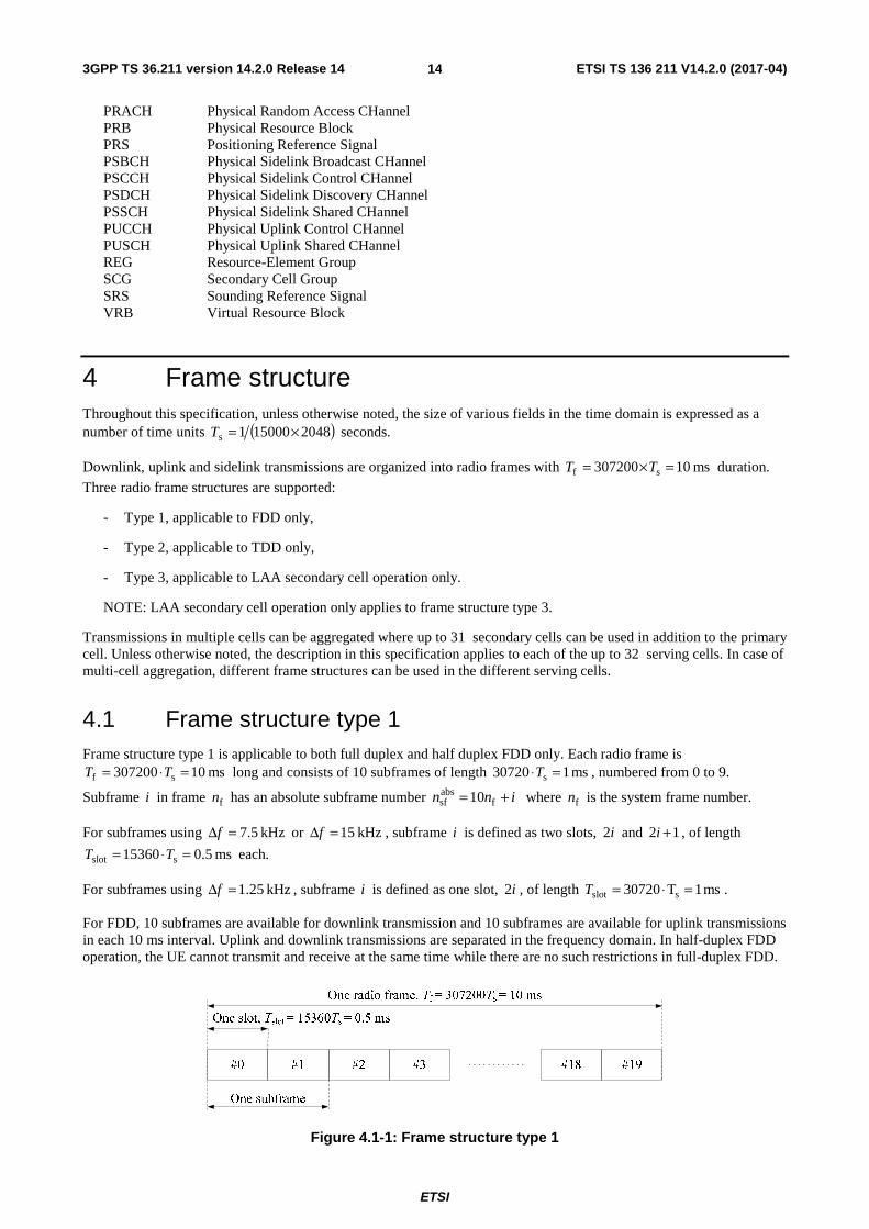
4 Frame structure Throughout this specification, unless otherwise noted, the size of various fields in the time domain is expressed as a number of time units ( )2048150001s ×=T seconds.
Downlink, uplink and sidelink transmissions are organized into radio frames with ms 10307200 sf =×= TT duration.
Three radio frame structures are supported:
- Type 1, applicable to FDD only,
- Type 2, applicable to TDD only,
- Type 3, applicable to LAA secondary cell operation only.
NOTE: LAA secondary cell operation only applies to frame structure type 3.
Transmissions in multiple cells can be aggregated where up to 31 secondary cells can be used in addition to the primary cell. Unless otherwise noted, the description in this specification applies to each of the up to 32 serving cells. In case of multi-cell aggregation, different frame structures can be used in the different serving cells.
4.1 Frame structure type 1 Frame structure type 1 is applicable to both full duplex and half duplex FDD only. Each radio frame is
ms 10307200 sf =⋅= TT long and consists of 10 subframes of length ms 107203 s =⋅T , numbered from 0 to 9.
Subframe i in frame fn has an absolute subframe number inn += fabssf 10 where fn is the system frame number.
For subframes using kHz 5.7=Δf or kHz 15=Δf , subframe i is defined as two slots, i2 and 12 +i , of length
ms 5.015360 sslot =⋅= TT each.
For subframes using kHz 25.1=Δf , subframe i is defined as one slot, i2 , of length ms 1T07203 sslot =⋅=T .
For FDD, 10 subframes are available for downlink transmission and 10 subframes are available for uplink transmissions in each 10 ms interval. Uplink and downlink transmissions are separated in the frequency domain. In half-duplex FDD operation, the UE cannot transmit and receive at the same time while there are no such restrictions in full-duplex FDD.
Figure 4.1-1: Frame structure type 1

3GPP TS 36.211 version 14.2.0 Release 14 ETSI TS 136 211 V14.2.0 (2017-04)
ETSI
15

3GPP TS 36.211 version 14.2.0 Release 14 ETSI TS 136 211 V14.2.0 (2017-04)
ETSI
16
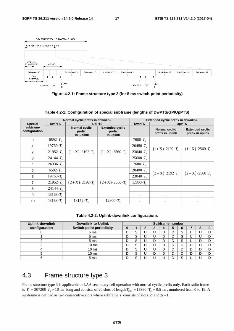
4.2 Frame structure type 2 Frame structure type 2 is applicable to TDD only. Each radio frame of length ms 10307200 sf =⋅= TT consists of two
half-frames of length ms 5153600 s =⋅T each. Each half-frame consists of five subframes of length ms 107203 s =⋅T .
Each subframe i is defined as two slots, i2 and 12 +i , of length ms 5.015360 sslot =⋅= TT each. Subframe i in frame
fn has an absolute subframe number inn += fabssf 10 where fn is the system frame number.
The uplink-downlink configuration in a cell may vary between frames and controls in which subframes uplink or downlink transmissions may take place in the current frame. The uplink-downlink configuration in the current frame is obtained according to Clause 13 in [4].
The supported uplink-downlink configurations are listed in Table 4.2-2 where, for each subframe in a radio frame, "D" denotes a downlink subframe reserved for downlink transmissions, "U" denotes an uplink subframe reserved for uplink transmissions and "S" denotes a special subframe with the three fields DwPTS, GP and UpPTS. The length of DwPTS and UpPTS is given by Table 4.2-1 subject to the total length of DwPTS, GP and UpPTS being equal to ms 107203 s =⋅T where X is the number of additional SC-FDMA symbols in UpPTS provided by the higher layer
parameter srs-UpPtsAdd if configured otherwise X is equal to 0. The UE is not expected to be configured with 2 additional UpPTS SC-FDMA symbols for special subframe configurations {3, 4, 7, 8} for normal cyclic prefix in downlink and special subframe configurations {2, 3, 5, 6} for extended cyclic prefix in downlink and 4 additional UpPTS SC-FDMA symbols for special subframe configurations {1, 2, 3, 4, 6, 7, 8} for normal cyclic prefix in downlink and special subframe configurations {1, 2, 3, 5, 6} for extended cyclic prefix in downlink.
Uplink-downlink configurations with both 5 ms and 10 ms downlink-to-uplink switch-point periodicity are supported.
- In case of 5 ms downlink-to-uplink switch-point periodicity, the special subframe exists in both half-frames.
- In case of 10 ms downlink-to-uplink switch-point periodicity, the special subframe exists in the first half-frame only.
Subframes 0 and 5 and DwPTS are always reserved for downlink transmission. UpPTS and the subframe immediately following the special subframe are always reserved for uplink transmission.
In case multiple cells are aggregated, the UE may assume that the guard period of the special subframe in the cells using frame structure type 2 have an overlap of at least s1456 T⋅ .
In case multiple cells with different uplink-downlink configurations in the current radio frame are aggregated and the UE is not capable of simultaneous reception and transmission in the aggregated cells, the following constraints apply:
- if the subframe in the primary cell is a downlink subframe, the UE shall not transmit any signal or channel on a secondary cell in the same subframe
- if the subframe in the primary cell is an uplink subframe, the UE is not expected to receive any downlink transmissions on a secondary cell in the same subframe
- if the subframe in the primary cell is a special subframe and the same subframe in a secondary cell is a downlink subframe, the UE is not expected to receive PDSCH/EPDCCH/PMCH/PRS transmissions in the secondary cell in the same subframe, and the UE is not expected to receive any other signals on the secondary cell in OFDM symbols that overlaps with the guard period or UpPTS in the primary cell.
3GPP TS 36.211 version 14.2.0 Release 14 ETSI TS 136 211 V14.2.0 (2017-04)
ETSI
17
Figure 4.2-1: Frame structure type 2 (for 5 ms switch-point periodicity)
Table 4.2-1: Configuration of special subframe (lengths of DwPTS/GP/UpPTS)
Special subframe
configuration
Normal cyclic prefix in downlink Extended cyclic prefix in downlink DwPTS UpPTS DwPTS UpPTS
Normal cyclic
prefix in uplink
Extended cyclic prefix
in uplink Normal cyclic
prefix in uplink Extended cyclic prefix in uplink
0 s6592 T⋅
( ) s1 X 2192 T+ ⋅ ⋅ ( ) s1 X 2560 T+ ⋅ ⋅
s7680 T⋅
( ) s1 X 2192 T+ ⋅ ⋅ ( ) s1 X 2560 T+ ⋅ ⋅ 1 s19760 T⋅ s20480 T⋅
2 s21952 T⋅ s23040 T⋅
3 s24144 T⋅ s25600 T⋅
4 s26336 T⋅ s7680 T⋅
( ) s2 X 2192 T+ ⋅ ⋅ ( ) s2 X 2560 T+ ⋅ ⋅ 5 s6592 T⋅
( ) s2 X 2192 T+ ⋅ ⋅ ( ) s2 X 2560 T+ ⋅ ⋅
s20480 T⋅
6 s19760 T⋅ s23040 T⋅
7 s21952 T⋅ s12800 T⋅
8 s24144 T⋅ - - -
9 s13168 T⋅ - - -
10 s13168 T⋅ s13152 T⋅ s12800 T⋅ - - -
Table 4.2-2: Uplink-downlink configurations
Uplink-downlink configuration
Downlink-to-Uplink Switch-point periodicity
Subframe number 0 1 2 3 4 5 6 7 8 9
0 5 ms D S U U U D S U U U 1 5 ms D S U U D D S U U D 2 5 ms D S U D D D S U D D 3 10 ms D S U U U D D D D D 4 10 ms D S U U D D D D D D 5 10 ms D S U D D D D D D D 6 5 ms D S U U U D S U U D
4.3 Frame structure type 3 Frame structure type 3 is applicable to LAA secondary cell operation with normal cyclic prefix only. Each radio frame is ms 10307200 sf =⋅= TT long and consists of 20 slots of length ms 5.0T15360 sslot =⋅=T , numbered from 0 to 19. A
subframe is defined as two consecutive slots where subframe i consists of slots i2 and 12 +i .

3GPP TS 36.211 version 14.2.0 Release 14 ETSI TS 136 211 V14.2.0 (2017-04)
ETSI
18
The 10 subframes within a radio frame are available for downlink or uplink transmissions. Downlink transmissions occupy one or more consecutive subframes, starting anywhere within a subframe and ending with the last subframe either fully occupied or following one of the DwPTS durations in Table 4.2-1. Uplink transmisisons occupy one or more consecutive subframes.

3GPP TS 36.211 version 14.2.0 Release 14 ETSI TS 136 211 V14.2.0 (2017-04)
ETSI
19
5 Uplink
5.1 Overview The smallest resource unit for uplink transmissions is denoted a resource element and is defined in clause 5.2.2.
5.1.1 Physical channels
An uplink physical channel corresponds to a set of resource elements carrying information originating from higher layers and is the interface defined between 3GPP TS 36.212 [3] and the present document 3GPP TS 36.211. The following uplink physical channels are defined:
- Physical Uplink Shared Channel, PUSCH
- Physical Uplink Control Channel, PUCCH
- Physical Random Access Channel, PRACH
5.1.2 Physical signals
An uplink physical signal is used by the physical layer but does not carry information originating from higher layers. The following uplink physical signals are defined:
- Reference signal
5.2 Slot structure and physical resources
5.2.1 Resource grid
The transmitted signal in each slot is described by one or several resource grids of RBsc
ULRB NN subcarriers and UL
symbN
SC-FDMA symbols. The resource grid is illustrated in Figure 5.2.1-1. The quantity ULRBN depends on the uplink
transmission bandwidth configured in the cell and shall fulfil
ULmax,RB
ULRB
ULmin,RB NNN ≤≤
where 6ULmin,RB =N and 110ULmax,
RB =N are the smallest and largest uplink bandwidths, respectively, supported by the
current version of this specification. The set of allowed values for ULRBN is given by 3GPP TS 36.101 [7].
The number of SC-FDMA symbols in a slot depends on the cyclic prefix length configured by the higher layer parameter UL-CyclicPrefixLength and is given in Table 5.2.3-1.
An antenna port is defined such that the channel over which a symbol on the antenna port is conveyed can be inferred from the channel over which another symbol on the same antenna port is conveyed. There is one resource grid per antenna port. The antenna ports used for transmission of a physical channel or signal depends on the number of antenna ports configured for the physical channel or signal as shown in Table 5.2.1-1. The index p~ is used throughout clause 5
when a sequential numbering of the antenna ports is necessary.

3GPP TS 36.211 version 14.2.0 Release 14 ETSI TS 136 211 V14.2.0 (2017-04)
ETSI
20
ULsymbN
slotT
0=l 1ULsymb −= Nl
RB
scU
LR
BN
N×
RB
scN
RBsc
ULsymb NN ×
),( lk
0=k
1RBsc
ULRB −= NNk
Figure 5.2.1-1: Uplink resource grid
Table 5.2.1-1: Antenna ports used for different physical channels and signals
Physical channel or signal Index p~
Antenna port number p as a function of the number of antenna ports configured
for the respective physical channel/signal 1 2 4
PUSCH
0 10 20 40 1 - 21 41 2 - - 42 3 - - 43
SRS
0 10 20 40 1 - 21 41 2 - - 42 3 - - 43
PUCCH 0 100 200 - 1 - 201 -
3GPP TS 36.211 version 14.2.0 Release 14 ETSI TS 136 211 V14.2.0 (2017-04)
ETSI
21
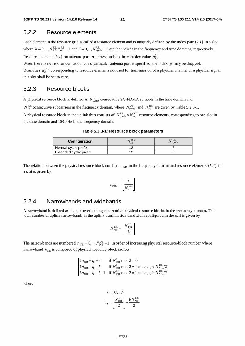
5.2.2 Resource elements
Each element in the resource grid is called a resource element and is uniquely defined by the index pair ( )lk, in a slot
where 1,...,0 RBsc
ULRB −= NNk and 1,...,0 UL
symb −= Nl are the indices in the frequency and time domains, respectively.
Resource element ( )lk, on antenna port p corresponds to the complex value )(,plka .
When there is no risk for confusion, or no particular antenna port is specified, the index p may be dropped.
Quantities )(,plka corresponding to resource elements not used for transmission of a physical channel or a physical signal
in a slot shall be set to zero.
5.2.3 Resource blocks
A physical resource block is defined as ULsymbN consecutive SC-FDMA symbols in the time domain and
RBscN consecutive subcarriers in the frequency domain, where UL
symbN and RBscN are given by Table 5.2.3-1.
A physical resource block in the uplink thus consists of RBsc
ULsymb NN × resource elements, corresponding to one slot in
the time domain and 180 kHz in the frequency domain.
Table 5.2.3-1: Resource block parameters
Configuration RBscN
ULsymbN
Normal cyclic prefix 12 7 Extended cyclic prefix 12 6
The relation between the physical resource block number PRBn in the frequency domain and resource elements ),( lk in
a slot is given by
⎥⎥⎦
⎥
⎢⎢⎣
⎢=
RBsc
PRBN
kn
5.2.4 Narrowbands and widebands
A narrowband is defined as six non-overlapping consecutive physical resource blocks in the frequency domain. The total number of uplink narrowbands in the uplink transmission bandwidth configured in the cell is given by
⎥⎥⎦
⎥
⎢⎢⎣
⎢=
6
ULRBUL
NBN
N
The narrowbands are numbered 1,...,0 ULNBNB −= Nn in order of increasing physical resource-block number where
narrowband NBn is composed of physical resource-block indices
⎪⎩
⎪⎨
⎧
≥=+++<=++
=++
2 and 12mod if16
2 and 12mod if6
02mod if6
ULNBNB
ULRB0NB
ULNBNB
ULRB0NB
ULRB0NB
NnNiin
NnNiin
Niin
where
2
6
2
5,...,1,0ULNB
ULRB
0NN
i
i
−⎥⎥⎦
⎥
⎢⎢⎣
⎢=
=

3GPP TS 36.211 version 14.2.0 Release 14 ETSI TS 136 211 V14.2.0 (2017-04)
ETSI
22
If 4ULNB ≥N , a wideband is defined as four non-overlapping narrowbands in the frequency domain. The total number of
uplink widebands in the uplink transmission bandwidth configured in the cell is given by
⎥⎥⎦
⎥
⎢⎢⎣
⎢=
4
ULNBUL
WBN
N
and the widebands are numbered 1,...,0 ULWBWB −= Nn in order of increasing narrowband number where wideband
WBn is composed of narrowband indices in +WB4 where 3,...,1,0=i .
If 4ULNB <N , then 1UL
WB =N and the single wideband is composed of the ULNBN non-overlapping narrowband(s).
5.2.5 Guard period for narrowband and wideband retuning
For BL/CE UEs, a guard period of at most retunesymbN SC-FDMA symbols is created for Tx-to-Tx frequency retuning
between two consecutive subframes. If the higher layer parameter ce-RetuningSymbols is set, then retunesymbN equals ce-
RetuningSymbols, otherwise 2retunesymb =N . If the higher layer parameter ce-pusch-maxBandwidth-config is set to 5 MHz,
then the rules for guard period creation defined in the remainder of this clause do not apply for retuning between narrowbands but for retuning between widebands and for transmissions involving multiple widebands.
- If the UE retunes from a first narrowband carrying PUSCH to a second narrowband carrying PUSCH, or if the UE retunes from a first narrowband carrying PUCCH to a second narrowband carrying PUCCH,
- if 1retunesymb =N , a guard period is created by the UE not transmitting the last SC-FDMA symbol in the first
subframe;
- if 2retunesymb =N , a guard period is created by the UE not transmitting the last SC-FDMA symbol in the first
subframe and the first SC-FDMA symbol in the second subframe.
- If the UE retunes from a first narrowband carrying PUCCH to a second narrowband carrying PUSCH,
- if the PUCCH uses a shortened PUCCH format and 1retunesymb =N , a guard period is created by the UE not
transmitting the last SC-FDMA symbol in the first subframe;
- if the PUCCH uses a shortened PUCCH format and 2retunesymb =N , a guard period is created by the UE not
transmitting the last SC-FDMA symbol in the first subframe and the first SC-FDMA symbol in the second subframe;
- if the PUCCH uses a normal PUCCH format, a guard period is created by the UE not transmitting the first retunesymbN SC-FDMA symbols in the second subframe.
- If the UE retunes from a first narrowband carrying PUSCH to a second narrowband carrying PUCCH,
- a guard period is created by the UE not transmitting the last retunesymbN SC-FDMA symbols in the first
subframe.
Furthermore, for BL/CE UEs configured with the higher layer parameter srs-UpPtsAdd, a guard period of at most retunesymbN SC-FDMA symbols is created for Tx-to-Tx frequency retuning between a first special subframe and a second
uplink subframe for frame structure type 2 according to:
- If the UE retunes from a first narrowband carrying SRS in the last UpPTS symbol to a second narrowband carrying PUSCH,
- a guard period is created by the UE not transmitting the first retunesymbN SC-FDMA symbols in the second
subframe.

3GPP TS 36.211 version 14.2.0 Release 14 ETSI TS 136 211 V14.2.0 (2017-04)
ETSI
23
- If the UE retunes from a first narrowband carrying SRS in the last but one UpPTS symbol, but not in the last UpPTS symbol, to a second narrowband carrying PUSCH,
- if 1retunesymb =N , a guard period is created by the UE not transmitting the last UpPTS symbol in the first
subframe;
- if 2retunesymb =N , a guard period is created by the UE not transmitting the last UpPTS symbol in the first
subframe and the first SC-FDMA symbol in the second subframe.
- If the UE retunes from a first narrowband carrying SRS to a second narrowband carrying PUCCH,
- if 1retunesymb =N , a guard period is created by the UE not transmitting the last UpPTS symbol in the first
subframe;
- if 2retunesymb =N , a guard period is created by the UE not transmitting the last UpPTS symbol in the first
subframe and the first SC-FDMA symbol in the second subframe.

3GPP TS 36.211 version 14.2.0 Release 14 ETSI TS 136 211 V14.2.0 (2017-04)
ETSI
24
5.3 Physical uplink shared channel The baseband signal representing the physical uplink shared channel is defined in terms of the following steps:
- scrambling
- modulation of scrambled bits to generate complex-valued symbols
- mapping of the complex-valued modulation symbols onto one or several transmission layers
- transform precoding to generate complex-valued symbols
- precoding of the complex-valued symbols
- mapping of precoded complex-valued symbols to resource elements
- generation of complex-valued time-domain SC-FDMA signal for each antenna port
Figure 5.3-1: Overview of uplink physical channel processing
5.3.1 Scrambling
For each codeword q , the block of bits )1(),...,0( )(bit
)()( −qqq Mbb , where )(bitqM is the number of bits transmitted in
codeword q on the physical uplink shared channel in one subframe, shall be scrambled with a UE-specific scrambling
sequence prior to modulation, resulting in a block of scrambled bits )1(~
),...,0(~ (q)
bit)()( −Mbb qq according to the
following pseudo code
Set i = 0
while )(bitqMi <
if x)()( =ib q // ACK/NACK or Rank Indication placeholder bits
1)(~ )( =ib q
else
if y)()( =ib q // ACK/NACK or Rank Indication repetition placeholder bits
)1(~
)(~ )()( −= ibib qq
else // Data or channel quality coded bits, Rank Indication coded bits or ACK/NACK coded bits
( ) 2mod)()()(~ )()()( icibib qqq +=
end if
end if
i = i + 1
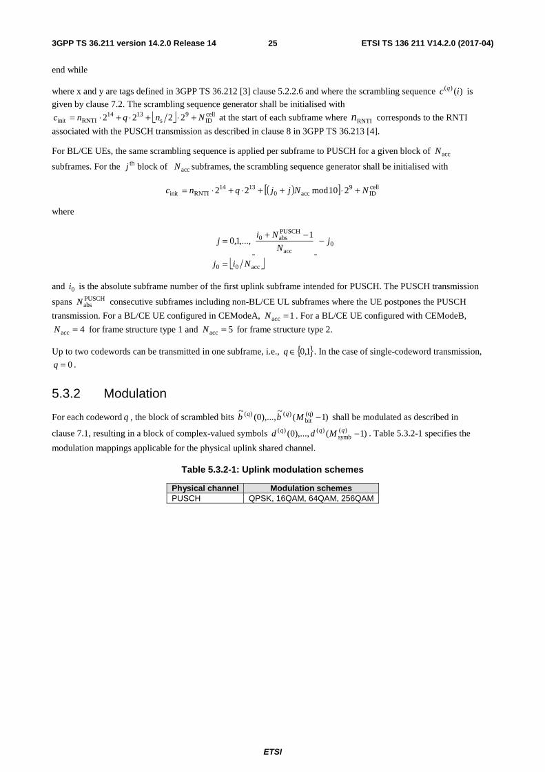
3GPP TS 36.211 version 14.2.0 Release 14 ETSI TS 136 211 V14.2.0 (2017-04)
ETSI
25
end while
where x and y are tags defined in 3GPP TS 36.212 [3] clause 5.2.2.6 and where the scrambling sequence )()( ic q is
given by clause 7.2. The scrambling sequence generator shall be initialised with
⎣ ⎦ cellID
9s
1314RNTIinit 2222 Nnqnc +⋅+⋅+⋅= at the start of each subframe where RNTIn corresponds to the RNTI
associated with the PUSCH transmission as described in clause 8 in 3GPP TS 36.213 [4].
For BL/CE UEs, the same scrambling sequence is applied per subframe to PUSCH for a given block of accN
subframes. For the thj block of accN subframes, the scrambling sequence generator shall be initialised with
( )[ ] cellID
9acc0
1314RNTIinit 210mod22 NNjjqnc +⋅++⋅+⋅=
where
⎣ ⎦acc00
0acc
PUSCHabs0 1
,...,1,0
Nij
jN
Nij
=
−⎥⎥⎦
⎥
⎢⎢⎣
⎢ −+=
and 0i is the absolute subframe number of the first uplink subframe intended for PUSCH. The PUSCH transmission
spans PUSCHabsN consecutive subframes including non-BL/CE UL subframes where the UE postpones the PUSCH
transmission. For a BL/CE UE configured in CEModeA, 1acc =N . For a BL/CE UE configured with CEModeB,
4acc =N for frame structure type 1 and 5acc =N for frame structure type 2.
Up to two codewords can be transmitted in one subframe, i.e., { }1,0∈q . In the case of single-codeword transmission,
0=q .
5.3.2 Modulation
For each codeword q , the block of scrambled bits )1(~
),...,0(~ (q)
bit)()( −Mbb qq shall be modulated as described in
clause 7.1, resulting in a block of complex-valued symbols )1(),...,0( )(symb
)()( −qqq Mdd . Table 5.3.2-1 specifies the
modulation mappings applicable for the physical uplink shared channel.
Table 5.3.2-1: Uplink modulation schemes
Physical channel Modulation schemes PUSCH QPSK, 16QAM, 64QAM, 256QAM

3GPP TS 36.211 version 14.2.0 Release 14 ETSI TS 136 211 V14.2.0 (2017-04)
ETSI
26
5.3.2A Layer mapping
The complex-valued modulation symbols for each of the codewords to be transmitted are mapped onto one or two
layers. Complex-valued modulation symbols )1(),...,0( )(symb
)()( −qqq Mdd for codeword q shall be mapped onto the
layers [ ]Tixixix )(...)()( )1()0( −= υ , 1,...,1,0 layersymb −= Mi where υ is the number of layers and layer
symbM is the number of
modulation symbols per layer.
5.3.2A.1 Layer mapping for transmission on a single antenna port
For transmission on a single antenna port, a single layer is used, 1=υ , and the mapping is defined by
)()( )0()0( idix =
with (0)symb
layersymb MM = .
5.3.2A.2 Layer mapping for spatial multiplexing
For spatial multiplexing, the layer mapping shall be done according to Table 5.3.2A.2-1. The number of layers υ is less than or equal to the number of antenna ports P used for transmission of the physical uplink shared channel. The case of a single codeword mapped to multiple layers is only applicable when the number of antenna ports used for PUSCH is four.
Table 5.3.2A.2-1: Codeword-to-layer mapping for spatial multiplexing
Number of layers Number of codewords Codeword-to-layer mapping
1,...,1,0 layersymb −= Mi
1 1 )()( )0()0( idix = )0(
symblayersymb MM =
2 1 )12()(
)2()()0()1(
)0()0(
+==
idix
idix 2)0(
symblayersymb MM =
2 2 )()( )0()0( idix = )1(
symb)0(
symblayersymb MMM ==
)()( )1()1( idix =
3 2
)()( )0()0( idix =
)12()(
)2()()1()2(
)1()1(
+==
idix
idix
2)1(symb
)0(symb
layersymb MMM ==
4 2 )12()(
)2()()0()1(
)0()0(
+==
idix
idix
22 )1(symb
)0(symb
layersymb MMM ==
)12()(
)2()()1()3(
)1()2(
+==
idix
idix
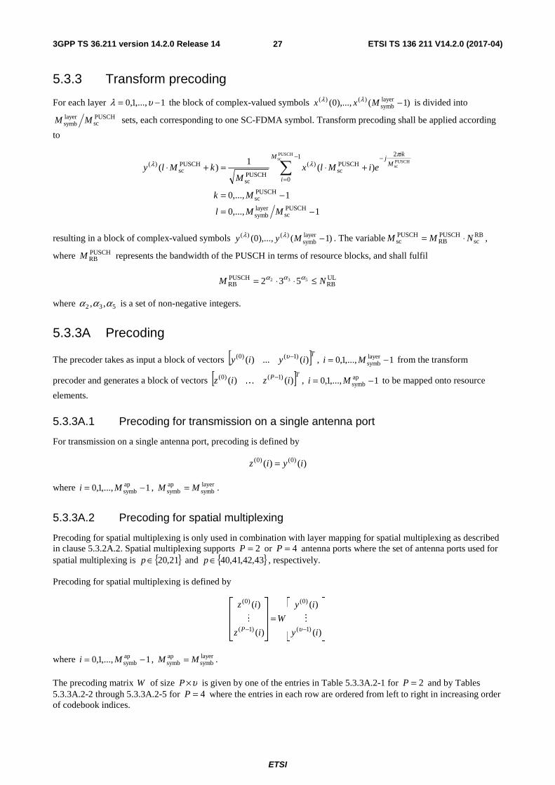
3GPP TS 36.211 version 14.2.0 Release 14 ETSI TS 136 211 V14.2.0 (2017-04)
ETSI
27
5.3.3 Transform precoding
For each layer 1,...,1,0 −= υλ the block of complex-valued symbols )1(),...,0( layersymb
)()( −Mxx λλ is divided into
PUSCHsc
layersymb MM sets, each corresponding to one SC-FDMA symbol. Transform precoding shall be applied according
to
1,...,0
1,...,0
)(1
)(
PUSCHsc
layersymb
PUSCHsc
1
0
2
PUSCHsc
)(
PUSCHsc
PUSCHsc
)(
PUSCHsc
PUSCHsc
−=
−=
+⋅=+⋅ ∑−
=
−
MMl
Mk
eiMlxM
kMlyM
i
M
ikj
πλλ
resulting in a block of complex-valued symbols )1(),...,0( layersymb
)()( −Myy λλ . The variable RBsc
PUSCHRB
PUSCHsc NMM ⋅= ,
where PUSCHRBM represents the bandwidth of the PUSCH in terms of resource blocks, and shall fulfil
ULRB
PUSCHRB
532 532 NM ≤⋅⋅= ααα
where 532 ,, ααα is a set of non-negative integers.
5.3.3A Precoding
The precoder takes as input a block of vectors [ ]Tiyiy )(...)( )1()0( −υ , 1,...,1,0 layersymb −= Mi from the transform
precoder and generates a block of vectors [ ]TP iziz )()( )1()0( −K , 1,...,1,0 ap
symb −= Mi to be mapped onto resource
elements.
5.3.3A.1 Precoding for transmission on a single antenna port
For transmission on a single antenna port, precoding is defined by
)()( )0()0( iyiz =
where 1,...,1,0 apsymb −= Mi , layer
symbapsymb MM = .
5.3.3A.2 Precoding for spatial multiplexing
Precoding for spatial multiplexing is only used in combination with layer mapping for spatial multiplexing as described in clause 5.3.2A.2. Spatial multiplexing supports 2=P or 4=P antenna ports where the set of antenna ports used for spatial multiplexing is { }21,20∈p and { }43,42,41,40∈p , respectively.
Precoding for spatial multiplexing is defined by
⎥⎥⎥
⎦
⎤
⎢⎢⎢
⎣
⎡
=⎥⎥⎥
⎦
⎤
⎢⎢⎢
⎣
⎡
−− )(
)(
)(
)(
)1(
)0(
)1(
)0(
iy
iy
W
iz
iz
P υMM
where 1,...,1,0 apsymb −= Mi , layer
symbapsymb MM = .
The precoding matrix W of size υ×P is given by one of the entries in Table 5.3.3A.2-1 for 2=P and by Tables 5.3.3A.2-2 through 5.3.3A.2-5 for 4=P where the entries in each row are ordered from left to right in increasing order of codebook indices.

3GPP TS 36.211 version 14.2.0 Release 14 ETSI TS 136 211 V14.2.0 (2017-04)
ETSI
28
Table 5.3.3A.2-1: Codebook for transmission on antenna ports { }21,20
Codebook index Number of layers
1=υ 2=υ
0 ⎥⎦
⎤⎢⎣
⎡
1
1
2
1 ⎥
⎦
⎤⎢⎣
⎡
10
01
2
1
1 ⎥⎦
⎤⎢⎣
⎡
−1
1
2
1 -
2 ⎥⎦
⎤⎢⎣
⎡
j
1
2
1 -
3 ⎥⎦
⎤⎢⎣
⎡
− j
1
2
1 -
4 ⎥⎦
⎤⎢⎣
⎡
0
1
2
1 -
5 ⎥⎦
⎤⎢⎣
⎡
1
0
2
1 -
Table 5.3.3A.2-2: Codebook for transmission on antenna ports { }43,42,41,40 with 1=υ
Codebook index Number of layers 1=υ
0 – 7
⎥⎥⎥⎥
⎦
⎤
⎢⎢⎢⎢
⎣
⎡
−1
1
1
1
2
1
⎥⎥⎥⎥
⎦
⎤
⎢⎢⎢⎢
⎣
⎡
j
j
1
1
2
1
⎥⎥⎥⎥
⎦
⎤
⎢⎢⎢⎢
⎣
⎡
−1
1
1
1
2
1
⎥⎥⎥⎥
⎦
⎤
⎢⎢⎢⎢
⎣
⎡
−−
j
j
1
1
2
1
⎥⎥⎥⎥
⎦
⎤
⎢⎢⎢⎢
⎣
⎡
j
j
1
1
2
1
⎥⎥⎥⎥
⎦
⎤
⎢⎢⎢⎢
⎣
⎡
1
1
2
1
j
j
⎥⎥⎥⎥
⎦
⎤
⎢⎢⎢⎢
⎣
⎡
−−
j
j
1
1
2
1
⎥⎥⎥⎥
⎦
⎤
⎢⎢⎢⎢
⎣
⎡
−−
1
1
2
1
j
j
8 – 15
⎥⎥⎥⎥
⎦
⎤
⎢⎢⎢⎢
⎣
⎡
−
1
1
1
1
2
1
⎥⎥⎥⎥
⎦
⎤
⎢⎢⎢⎢
⎣
⎡
−
−
j
j
1
1
2
1
⎥⎥⎥⎥
⎦
⎤
⎢⎢⎢⎢
⎣
⎡
−−−
1
1
1
1
2
1
⎥⎥⎥⎥
⎦
⎤
⎢⎢⎢⎢
⎣
⎡
−−
j
j
1
1
2
1
⎥⎥⎥⎥
⎦
⎤
⎢⎢⎢⎢
⎣
⎡
−
−
j
j
1
1
2
1
⎥⎥⎥⎥
⎦
⎤
⎢⎢⎢⎢
⎣
⎡
−
−
1
1
2
1
j
j
⎥⎥⎥⎥
⎦
⎤
⎢⎢⎢⎢
⎣
⎡
−−
j
j
1
1
2
1
⎥⎥⎥⎥
⎦
⎤
⎢⎢⎢⎢
⎣
⎡
−−
1
1
2
1
j
j
16 – 23
⎥⎥⎥⎥
⎦
⎤
⎢⎢⎢⎢
⎣
⎡
0
1
0
1
2
1
⎥⎥⎥⎥
⎦
⎤
⎢⎢⎢⎢
⎣
⎡
−0
1
0
1
2
1
⎥⎥⎥⎥
⎦
⎤
⎢⎢⎢⎢
⎣
⎡
0
0
1
2
1
j
⎥⎥⎥⎥
⎦
⎤
⎢⎢⎢⎢
⎣
⎡
−0
0
1
2
1
j
⎥⎥⎥⎥
⎦
⎤
⎢⎢⎢⎢
⎣
⎡
1
0
1
0
2
1
⎥⎥⎥⎥
⎦
⎤
⎢⎢⎢⎢
⎣
⎡
−1
0
1
0
2
1
⎥⎥⎥⎥
⎦
⎤
⎢⎢⎢⎢
⎣
⎡
j
0
1
0
2
1
⎥⎥⎥⎥
⎦
⎤
⎢⎢⎢⎢
⎣
⎡
− j
0
1
0
2
1
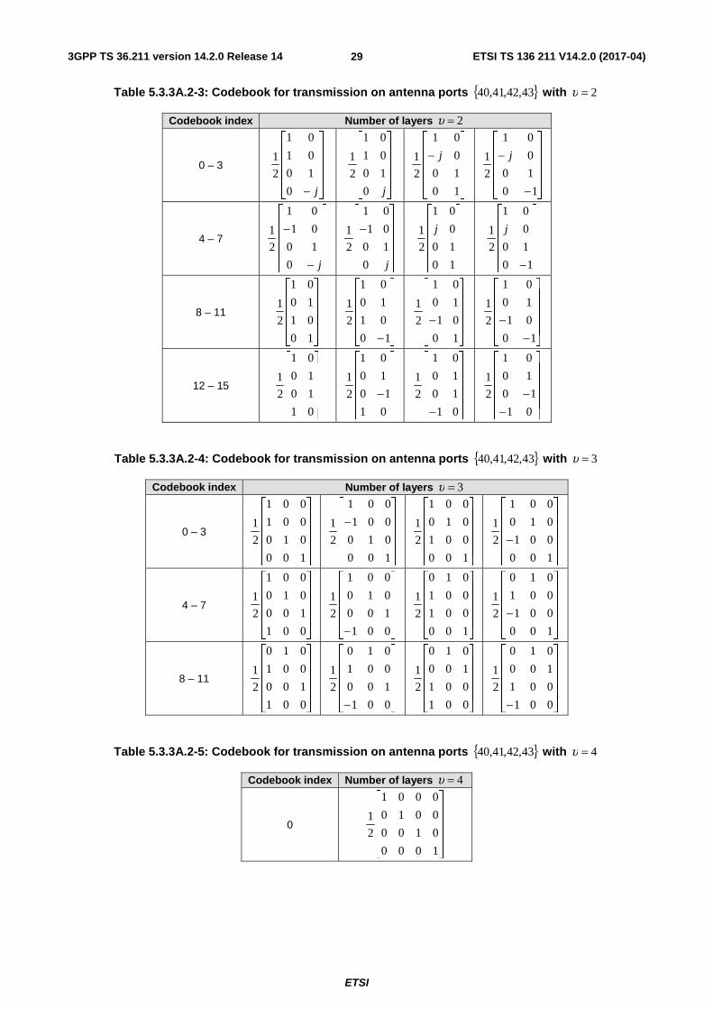
3GPP TS 36.211 version 14.2.0 Release 14 ETSI TS 136 211 V14.2.0 (2017-04)
ETSI
29
Table 5.3.3A.2-3: Codebook for transmission on antenna ports { }43,42,41,40 with 2=υ
Codebook index Number of layers 2=υ
0 – 3
⎥⎥⎥⎥
⎦
⎤
⎢⎢⎢⎢
⎣
⎡
− j0
10
01
01
2
1
⎥⎥⎥⎥
⎦
⎤
⎢⎢⎢⎢
⎣
⎡
j0
10
01
01
2
1
⎥⎥⎥⎥
⎦
⎤
⎢⎢⎢⎢
⎣
⎡
−
10
10
0
01
2
1 j
⎥⎥⎥⎥
⎦
⎤
⎢⎢⎢⎢
⎣
⎡
−
−
10
10
0
01
2
1 j
4 – 7
⎥⎥⎥⎥
⎦
⎤
⎢⎢⎢⎢
⎣
⎡
−
−
j0
10
01
01
2
1
⎥⎥⎥⎥
⎦
⎤
⎢⎢⎢⎢
⎣
⎡
−
j0
10
01
01
2
1
⎥⎥⎥⎥
⎦
⎤
⎢⎢⎢⎢
⎣
⎡
10
10
0
01
2
1 j
⎥⎥⎥⎥
⎦
⎤
⎢⎢⎢⎢
⎣
⎡
−10
10
0
01
2
1 j
8 – 11
⎥⎥⎥⎥
⎦
⎤
⎢⎢⎢⎢
⎣
⎡
10
01
10
01
2
1
⎥⎥⎥⎥
⎦
⎤
⎢⎢⎢⎢
⎣
⎡
−10
01
10
01
2
1
⎥⎥⎥⎥
⎦
⎤
⎢⎢⎢⎢
⎣
⎡
−10
01
10
01
2
1
⎥⎥⎥⎥
⎦
⎤
⎢⎢⎢⎢
⎣
⎡
−−
10
01
10
01
2
1
12 – 15
⎥⎥⎥⎥
⎦
⎤
⎢⎢⎢⎢
⎣
⎡
01
10
10
01
2
1
⎥⎥⎥⎥
⎦
⎤
⎢⎢⎢⎢
⎣
⎡
−01
10
10
01
2
1
⎥⎥⎥⎥
⎦
⎤
⎢⎢⎢⎢
⎣
⎡
− 01
10
10
01
2
1
⎥⎥⎥⎥
⎦
⎤
⎢⎢⎢⎢
⎣
⎡
−−01
10
10
01
2
1
Table 5.3.3A.2-4: Codebook for transmission on antenna ports { }43,42,41,40 with 3=υ
Codebook index Number of layers 3=υ
0 – 3
⎥⎥⎥⎥
⎦
⎤
⎢⎢⎢⎢
⎣
⎡
100
010
001
001
2
1
⎥⎥⎥⎥
⎦
⎤
⎢⎢⎢⎢
⎣
⎡
−
100
010
001
001
2
1
⎥⎥⎥⎥
⎦
⎤
⎢⎢⎢⎢
⎣
⎡
100
001
010
001
2
1
⎥⎥⎥⎥
⎦
⎤
⎢⎢⎢⎢
⎣
⎡
−100
001
010
001
2
1
4 – 7
⎥⎥⎥⎥
⎦
⎤
⎢⎢⎢⎢
⎣
⎡
001
100
010
001
2
1
⎥⎥⎥⎥
⎦
⎤
⎢⎢⎢⎢
⎣
⎡
− 001
100
010
001
2
1
⎥⎥⎥⎥
⎦
⎤
⎢⎢⎢⎢
⎣
⎡
100
001
001
010
2
1
⎥⎥⎥⎥
⎦
⎤
⎢⎢⎢⎢
⎣
⎡
−100
001
001
010
2
1
8 – 11
⎥⎥⎥⎥
⎦
⎤
⎢⎢⎢⎢
⎣
⎡
001
100
001
010
2
1
⎥⎥⎥⎥
⎦
⎤
⎢⎢⎢⎢
⎣
⎡
− 001
100
001
010
2
1
⎥⎥⎥⎥
⎦
⎤
⎢⎢⎢⎢
⎣
⎡
001
001
100
010
2
1
⎥⎥⎥⎥
⎦
⎤
⎢⎢⎢⎢
⎣
⎡
− 001
001
100
010
2
1
Table 5.3.3A.2-5: Codebook for transmission on antenna ports { }43,42,41,40 with 4=υ
Codebook index Number of layers 4=υ
0
⎥⎥⎥⎥
⎦
⎤
⎢⎢⎢⎢
⎣
⎡
1000
0100
0010
0001
2
1

3GPP TS 36.211 version 14.2.0 Release 14 ETSI TS 136 211 V14.2.0 (2017-04)
ETSI
30
5.3.4 Mapping to physical resources
For each antenna port p used for transmission of the PUSCH in a subframe the block of complex-valued symbols
)1(),...,0( apsymb
)~()~( −Mzz pp shall be multiplied with the amplitude scaling factor PUSCHβ in order to conform to the
transmit power PUSCHP specified in clause 5.1.1.1 in 3GPP TS 36.213 [4], and mapped in sequence starting with
)0()~( pz to physical resource blocks on antenna port p and assigned for transmission of PUSCH. The relation between
the index p~ and the antenna port number p is given by Table 5.2.1-1. The mapping to resource elements ( )lk,
corresponding to the physical resource blocks assigned for transmission and
- not used for transmission of reference signals, and
- not part of the last SC-FDMA symbol in a subframe, if the UE transmits SRS in the same subframe in the same serving cell, and
- not part of the last SC-FDMA symbol in a subframe configured with cell-specific SRS for non-BL/CE UEs and BL/CE UEs in CEModeA, if the PUSCH transmission partly or fully overlaps with the cell-specific SRS bandwidth, and
- not part of an SC-FDMA symbol reserved for possible SRS transmission in a UE-specific aperiodic SRS subframe in the same serving cell, and
- not part of an SC-FDMA symbol reserved for possible SRS transmission in a UE-specific periodic SRS subframe in the same serving cell when the UE is configured with multiple TAGs
- not part of the first SC-FDMA symbol in a subframe if the associated DCI indicates PUSCH starting position ‘01’, ‘10’, or ‘11
- not part of the last SC-FDMA symbol in a subframe if the associated DCI indicates PUSCH ending symbol ‘1’
shall be in increasing order of first the index k , then the index l , starting with the first slot in an uplink subframe. For
the UpPTS, if dmrsLess-UpPts is set to true, the mapping shall start at symbol pPtssymPUSCH_UNl −= ULsymb in the
second slot of a special subframe, otherwise, the mapping shall start at symbol 1ULsymb −−= pPtssymPUSCH_UNl in
the second slot of a special subframe.
For BL/CE UEs, the PUSCH transmission is restricted as follows:
- For CEModeA, if the PUSCH is associated with C-RNTI or SPS C-RNTI and the higher layer parameter ce-pusch-maxBandwidth-config is set to 5 MHz, the maximum number of allocatable PRBs for PUSCH is 24 PRBs. The allocatable PRBs include the PRBs belonging to the narrowbands defined in clause 5.2.4 and the odd PRB at the center of the uplink system bandwidth in case of odd total number of uplink PRBs. If a resource assignment or frequency hopping would result in a PUSCH resource allocation outside the allocatable PRBs then the PUSCH transmission in that subframe is dropped.
- For all other cases, the maximum number of allocatable PRBs for PUSCH is 6 PRBs restricted to one of the narrowbands defined in clause 5.2.4.
For BL/CE UEs in CEModeB, resource elements in the last SC-FDMA symbol in a subframe configured with cell-specific SRS shall be counted in the PUSCH mapping but not used for transmission of the PUSCH.
For BL/CE UEs, if one or more SC-FDMA symbol(s) are left empty due to guard period for narrowband retuning, the affected SC-FDMA symbol(s) shall be counted in the PUSCH mapping but not used for transmission of the PUSCH.
For a UE configured with SRS carrier switching, if the first symbol in a subframe collides with the switching time associated with an SRS transmission, the resource elements in the first OFDM symbol shall be counted in the PUSCH mapping but not used for transmission of PUSCH.
For a UE configured with SRS carrier switching, if the last symbol in a subframe is not counted in the PUSCH mapping and the second-to-last symbol in the subframe collides with the switching time associated with an SRS transmission, the resource elements in the second-to-last OFDM symbol shall be counted in the PUSCH mapping but not used for transmission of PUSCH.
3GPP TS 36.211 version 14.2.0 Release 14 ETSI TS 136 211 V14.2.0 (2017-04)
ETSI
31
If uplink frequency-hopping is disabled or the resource blocks allocated for PUSCH transmission are not contiguous in frequency, the set of physical resource blocks to be used for transmission is given by VRBPRB nn = where VRBn is
obtained from the uplink scheduling grant as described in clause 8.1 in 3GPP TS 36.213 [4].
If uplink frequency-hopping with type 1 PUSCH hopping is enabled, the set of physical resource blocks to be used for transmission is given by clause 8.4.1 in 3GPP TS 36.213 [4].
If uplink frequency-hopping with predefined hopping pattern is enabled, the set of physical resource blocks to be used for transmission in slot sn is given by the scheduling grant together with a predefined pattern according to
( ) ( ) ( )( )( )⎣ ⎦
⎡ ⎤
⎡ ⎤⎪⎩
⎪⎨⎧
>−
==
⎪⎩
⎪⎨⎧
>+
==
⎩⎨⎧
−−
=
⋅⋅−−+⋅+=
12
1~
12)(~1)(~
)(
hopping subframeinter and intra
hopping subframeinter2
)mod()(mod~21~)(~
HORBVRB
VRBVRB
HORBsPRB
sPRBsPRB
s
s
sbsbRBm
sbRBVRB
sbRB
sbRBhopVRBsPRB
sb
sb
sb
sb
NNn
Nnn
NNnn
Nnnnn
n
ni
NNifNnNNifnnn
where VRBn is obtained from the scheduling grant as described in clause 8.1 in 3GPP TS 36.213 [4]. The parameter
pusch-HoppingOffset, HORBN , is provided by higher layers. The size sb
RBN of each sub-band is given by,
( )⎣ ⎦⎪⎩
⎪⎨⎧
>−−
==
12mod
1
sbsbHORB
HORB
ULRB
sbULRBsb
RBNNNNN
NNN
where the number of sub-bands sbN is given by higher layers. The function { }1,0)(m ∈if determines whether mirroring
is used or not. The parameter Hopping-mode provided by higher layers determines if hopping is "inter-subframe" or "intra and inter-subframe".
The hopping function )(hop if and the function )(m if are given by
⎪⎪⎪
⎩
⎪⎪⎪
⎨
⎧
>+−⎟⎟
⎠
⎞
⎜⎜
⎝
⎛×+−
=×+−
=
=
∑
∑
+⋅
+⋅=
+⋅−
+⋅
+⋅=
+⋅−
2mod)1)1mod(2)()1((
2mod)2)()1((
10
)(
sbsbsb
910
110
)110(hop
sbsb
910
110
)110(hop
sb
hop
NNNkcif
NNkcif
N
ifi
ik
ik
i
ik
ik
⎪⎩
⎪⎨
⎧
>⋅−=
−==
1)10(
hopping subframeinter and 12mod_NBCURRENT_TX
hopping subframeinter and intra and 12mod
)(
sb
sb
sb
m
Nic
N
Ni
if
where 0)1(hop =−f and the pseudo-random sequence )(ic is given by clause 7.2 and CURRENT_TX_NB indicates the
transmission number for the transport block transmitted in slot sn as defined in [8]. The pseudo-random sequence
generator shall be initialised with cellIDinit Nc = for frame structure type 1 and cell
IDf9
init )4mod(2 Nnc +⋅= for frame
structure type 2
at the start of each frame.
For BL/CE UEs, the PRB resources for PUSCH transmission in the first subframe are obtained from the DCI as
described in clauses 5.3.3.1.10 and 5.3.3.1.11 in [3]. The PUSCH is transmitted with 1PUSCHrep ≥N repetitions. The
PUSCH transmission spans PUSCHrep
PUSCHabs NN ≥ consecutive subframes, including non-BL/CE UL subframes where the
UE postpones the PUSCH transmission if 1PUSCHrep >N . For BL/CE UE in CEModeA, PUSCH frequency hopping is

3GPP TS 36.211 version 14.2.0 Release 14 ETSI TS 136 211 V14.2.0 (2017-04)
ETSI
32
enabled when the higher-layer parameter pusch-HoppingConfig is set and the frequency hopping flag in DCI format 6-0A indicates frequency hopping, otherwise frequency hopping is disabled. For BL/CE UE in CEModeB, PUSCH frequency hopping is enabled when the higher-layer parameter pusch-HoppingConfig is set, otherwise frequency hopping is disabled. If frequency hopping is not enabled for PUSCH, all PUSCH repetitions are located at the same
PRB resources. If frequency hopping is enabled for PUSCH, PUSCH is transmitted in subframe i within the PUSCHabsN
consecutive uplink subframes using the same number of consecutive PRBs as in the previous subframe starting from the same starting PRB resource within narrowband
( )( ) ⎣ ⎦( )( ) ⎣ ⎦
⎣ ⎦1
12mod ifmod
02mod if
PUSCHabs00
ULch,NB00
0ULch,
NBULNB
PUSCHhopNB,NB
0ULch,
NBNBNB 0
0
−+≤≤
=
⎪⎩
⎪⎨⎧
=−+=−
=
Niii
Nij
jNiNfn
jNinn i
ii
where 0i is the absolute subframe number of the first UL subframe intended for carrying the PUSCH and ULch,NBN and
PUSCHhopNB,f are cell-specific higher-layer parameters. For the PUSCH
absN consecutive subframes, the UE shall not transmit
PUSCH in subframe i if it is not a BL/CE UL subframe.
For BL/CE UEs, PUSCH transmission associated with Temporary C-RNTI, frequency hopping of the PUSCH is enabled when higher layer parameter rar-HoppingConfig is set. Further
- if PRACH CE level 0 or 1 is used for the last PRACH attempt, ULch,NBN is set to the higher layer parameter
interval-UlHoppingConfigCommonModeA;
- if PRACH CE level 2 or 3 is used for the last PRACH attempt, ULch,NBN is set to the higher layer parameter
interval-UlHoppingConfigCommonModeB.
For BL/CE UEs in CEModeB, for PUSCH transmission not associated with Temporary C-RNTI, for frame structure type 1, after a transmission duration of s30720256 T⋅ time units (which may include non-BL/CE UL subframes), a gap
of s3072040 T⋅ time units shall be inserted, as specified in TS 36.331 [9]. BL/CE UL subframes within the gap of
s3072040 T⋅ time units shall be counted for the PUSCH resource mapping but not used for transmission of the
PUSCH.
For BL/CE UEs, for PUSCH transmission associated with Temporary C-RNTI for frame structure type 1, and if PRACH CE level 2 or 3 is used for the last PRACH attempt, after a transmission duration of s30720256 T⋅ time units
(which may include non-BL/CE UL subframes), a gap of s3072040 T⋅ time units shall be inserted. BL/CE UL
subframes within the gap of s3072040 T⋅ time units shall be counted for the PUSCH resource mapping but not used for
transmission of the PUSCH.
For UEs configured with PUSCHEnh-Configuration, the number of PUSCH subframe repetitions PUSCHrepN and the
PRB resources for PUSCH transmission in the first subframe are obtained from the DCI as described in clause 5.3.3.1.1C in [3]. PUSCH frequency hopping is enabled when the higher-layer parameters pusch-HoppingOffsetPUSCHEnh and interval-ULHoppingPUSCHEnh are set and the frequency hopping flag in DCI format 0C indicates frequency hopping, otherwise frequency hopping is disabled. If frequency hopping is not enabled for PUSCH, the PUSCH repetitions are located at the same PRB resources as in the first subframe. If frequency hopping is
enabled for PUSCH, PUSCH is transmitted in subframe i within the PUSCHrepN consecutive uplink subframes using the
PRB resources starting at PRB index ( )inPRB
( )( ) ⎣ ⎦( )( ) ⎣ ⎦
⎣ ⎦1
12mod ifmod
02mod if
PUSCHrep00
PUSCHhopPRB,00
0PUSCH
hopPRB,ULPRB
PUSCHhopPRB,PRB
0PUSCH
hopPRB,PRBPRB 0
0
−+≤≤
=
⎪⎩
⎪⎨⎧
=−+=−
=
Niii
Nij
jNiNfn
jNinn i
ii

3GPP TS 36.211 version 14.2.0 Release 14 ETSI TS 136 211 V14.2.0 (2017-04)
ETSI
33
where 0i is the absolute subframe number of the first UL subframe carrying the PUSCH and PUSCHhopPRB,N is given by the
higher-layer parameter pusch-HoppingOffsetPUSCHEnh and PUSCHhopPRB,f is given by the higher-layer parameter interval-
ULHoppingPUSCHEnh.
5.4 Physical uplink control channel The physical uplink control channel, PUCCH, carries uplink control information. Simultaneous transmission of PUCCH and PUSCH from the same UE is supported if enabled by higher layers. For frame structure type 2, the PUCCH is not transmitted in the UpPTS field.
The physical uplink control channel supports multiple formats as shown in Table 5.4-1 with different number of bits per
subframe, where PUCCH4RBM represents the bandwidth of the PUCCH format 4 as defined by clause 5.4.2B, and
PUCCH0N and PUCCH
1N are defined in Table 5.4.2C-1.
Formats 2a and 2b are supported for normal cyclic prefix only.
Table 5.4-1: Supported PUCCH formats
PUCCH format Modulation scheme Number of bits per subframe, bitM
1 N/A N/A 1a BPSK 1 1b QPSK 2 2 QPSK 20 2a QPSK+BPSK 21 2b QPSK+QPSK 22 3 QPSK 48
4 QPSK ( ) 2PUCCH1
PUCCH0
RBsc
PUCCH4RB ⋅+⋅⋅ NNNM
5 QPSK ( )PUCCH1
PUCCH0
RBsc NNN +⋅
All PUCCH formats use a cyclic shift, ),( scellcs lnn , which varies with the symbol number l and the slot number sn
according to
∑ = ⋅++⋅= 7
0 sULsymbs
cellcs 2)88(),(
iiilnNclnn
where the pseudo-random sequence )(ic is defined by clause 7.2. The pseudo-random sequence generator shall be
initialized with RSIDinit nc = , where RS
IDn is given by clause 5.5.1.5 with cellIDN corresponding to the primary cell, at the
beginning of each radio frame.
The physical resources used for PUCCH depends on two parameters, (2)RBN and (1)
csN , given by higher layers.
The variable 0(2)RB ≥N denotes the bandwidth in terms of resource blocks that are available for use by PUCCH formats
2/2a/2b transmission in each slot. The variable (1)csN denotes the number of cyclic shift used for PUCCH formats
1/1a/1b in a resource block used for a mix of formats 1/1a/1b and 2/2a/2b. The value of (1)csN is an integer multiple of
PUCCHshiftΔ within the range of {0, 1, …, 7}, where PUCCH
shiftΔ is provided by higher layers. No mixed resource block is
present if 0(1)cs =N . At most one resource block in each slot supports a mix of formats 1/1a/1b and 2/2a/2b.
Resources used for transmission of PUCCH formats 1/1a/1b, 2/2a/2b, 3, 4, and 5 are represented by the non-negative
indices )~(1,PUCCH
pn , )2(8
(1)cs
RBsc
(1)csRB
sc(2)RB
)~(2,PUCCH −−⋅
⎥⎥⎥
⎤
⎢⎢⎢
⎡+< NN
NNNn p , )~(3,
PUCCHpn , (4)
PUCCHn and (5)PUCCHn , respectively.

3GPP TS 36.211 version 14.2.0 Release 14 ETSI TS 136 211 V14.2.0 (2017-04)
ETSI
34
5.4.1 PUCCH formats 1, 1a and 1b
For PUCCH format 1, information is carried by the presence/absence of transmission of PUCCH from the UE. In the remainder of this clause, 1)0( =d shall be assumed for PUCCH format 1.
For PUCCH formats 1a and 1b, one or two explicit bits are transmitted, respectively. The block of bits )1(),...,0( bit −Mbb shall be modulated as described in Table 5.4.1-1, resulting in a complex-valued symbol )0(d .
The modulation schemes for the different PUCCH formats are given by Table 5.4-1.
The complex-valued symbol )0(d shall be multiplied with a cyclically shifted length 12PUCCHseq =N sequence )(
)(,
~nr p
vuα
for each of the P antenna ports used for PUCCH transmission according to
1,...,1,0 ),()0(1
)( PUCCHseq
),(,
),~( ~ −=⋅= NnnrdP
ny pvu
p δαδ
where )(),(
,~
nr pvu
δα is defined by clause 5.5.1 with PUCCH
seqRSsc NM = and 0=δ . The antenna-port specific cyclic shift p~α
varies between symbols and slots as defined below.
The block of complex-valued symbols )1(),...,0( PUCCHseq
)~()~( −Nyy pp shall be scrambled by )( snS and block-wise
spread with the antenna-port specific orthogonal sequence )()~(oc
iw pn according to
( ) ( )nymwnSnNmNNmz pn
p )~(s
PUCCHseq
PUCCHseq
PUCCHSF
)~( )()(' )p~(oc
⋅⋅=+⋅+⋅⋅
where
1,0'
1,...,0
1,...,0PUCCHseq
PUCCHSF
=
−=
−=
m
Nn
Nm
and
⎩⎨⎧ =′
=otherwise
02mod)(if1)( 2
s~
s πjp
e
nnnS
with PUCCHSFN for the two slots in a subframe given by Table 5.4.1-1a. The sequence )()~(
ociw pn
is given by Table 5.4.1-2
and Table 5.4.1-3 and )( s~ nnp′ is defined below.
Resources used for transmission of PUCCH format 1, 1a and 1b are identified by a resource index )~(1,PUCCH
pn from which
the orthogonal sequence index )( s)~(
oc nn p and the cyclic shift ),( s~ lnpα are determined according to
⎣ ⎦⎣ ⎦
( )( )[ ]( )[ ]⎪
⎩
⎪⎨
⎧
′+Δ⋅′+
′Δ+Δ⋅′+=
⋅=
⎪⎩
⎪⎨
⎧
′Δ⋅′⋅
′Δ⋅′=
prefix cyclic extendedfor modmod2)()(),(
prefix cyclic normalfor modmodmod)()(),(),(
),(2),(
prefix cyclic extendedfor )(2
prefix cyclic normalfor )()(
RBscs
)~(oc
PUCCHshifts~s
cellcs
RBsc
PUCCHshifts
)~(oc
PUCCHshifts~s
cellcs
s)~(
cs
RBscs
)~(css~
PUCCHshifts~
PUCCHshifts~
s)~(
oc
NNnnnnlnn
NNnnnnlnnlnn
Nlnnln
Nnn
Nnnnn
pp
ppp
pp
p
pp
πα
where
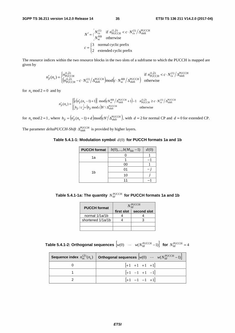
3GPP TS 36.211 version 14.2.0 Release 14 ETSI TS 136 211 V14.2.0 (2017-04)
ETSI
35
⎩⎨⎧
=
⎪⎩
⎪⎨⎧ Δ⋅<=′
prefix cyclic extended2
prefix cyclic normal3
otherwise
ifRBsc
PUCCHshift
(1)cs
)~(1,PUCCH
(1)cs
c
N
NcnNN
p
The resource indices within the two resource blocks in the two slots of a subframe to which the PUCCH is mapped are given by
( ) ( )⎪⎩
⎪⎨⎧
Δ⋅Δ⋅−Δ⋅<
=′otherwisemod
if)(
PUCCHshift
RBsc
PUCCHshift
(1)cs
)~,1(PUCCH
PUCCHshift
(1)cs
)~,1(PUCCH
)~,1(PUCCH
s~NcNcn
Ncnnnn
p
pp
p
for 02mods =n and by
( )[ ] ( )⎣ ⎦ ( )⎪⎩
⎪⎨⎧
Δ+
Δ⋅≥−+Δ+−′=′
otherwise/'mod/
11mod1)1()(
PUCCHshift~~
PUCCHshift
(1)cs
)~,1(PUCCH
PUCCHshift
RBscs~
s~
Nchch
NcncNnncnn
pp
pp
p
for 12mods =n , where ( ) ( )PUCCHshifs~~ 'mod)1( tpp cNdnnh Δ+−′= , with 2=d for normal CP and 0=d for extended CP.
The parameter deltaPUCCH-Shift PUCCHshiftΔ is provided by higher layers.
Table 5.4.1-1: Modulation symbol )0(d for PUCCH formats 1a and 1b
PUCCH format )1(),...,0( bit −Mbb )0(d
1a 0 1 1 1−
1b
00 1 01 j−
10 j
11 1−
Table 5.4.1-1a: The quantity PUCCHSFN for PUCCH formats 1a and 1b
PUCCH format PUCCHSFN
first slot second slot normal 1/1a/1b 4 4
shortened 1/1a/1b 4 3
Table 5.4.1-2: Orthogonal sequences [ ])1()0( PUCCHSF −Nww L for 4PUCCH
SF =N
Sequence index )( s)~(
oc nn p Orthogonal sequences [ ])1()0( PUCCHSF −Nww L
0 [ ]1111 ++++ 1 [ ]1111 −+−+ 2 [ ]1111 +−−+

3GPP TS 36.211 version 14.2.0 Release 14 ETSI TS 136 211 V14.2.0 (2017-04)
ETSI
36
Table 5.4.1-3: Orthogonal sequences [ ])1()0( PUCCHSF −Nww L for 3PUCCH
SF =N
Sequence index )( s)~(
oc nn p Orthogonal sequences [ ])1()0( PUCCHSF −Nww L
0 [ ]111
1 [ ]34321 ππ jj ee
2 [ ]32341 ππ jj ee

3GPP TS 36.211 version 14.2.0 Release 14 ETSI TS 136 211 V14.2.0 (2017-04)
ETSI
37
5.4.2 PUCCH formats 2, 2a and 2b
The block of bits )19(),...,0( bb shall be scrambled with a UE-specific scrambling sequence, resulting in a block of
scrambled bits )19(~
),...,0(~
bb according to
( ) 2mod)()()(~
icibib +=
where the scrambling sequence )(ic is given by clause 7.2. The scrambling sequence generator shall be initialised with
⎣ ⎦( ) ( ) RNTI16cell
IDsinit 21212 nNnc +⋅+⋅+= at the start of each subframe where RNTIn is C-RNTI.
The block of scrambled bits )19(~
),...,0(~
bb shall be QPSK modulated as described in clause 7.1, resulting in a block of
complex-valued modulation symbols )9(),...,0( dd .
Each complex-valued symbol )9(),...,0( dd shall be multiplied with a cyclically shifted length 12PUCCHseq =N sequence
)(),(
,~
nr pvu
δα for each of the P antenna ports used for PUCCH transmission according to
1,...,1,0
9,...,1,0
)()(1
)(
RBsc
),(,
PUCCHseq
)~( ~
−=
=
⋅=+⋅
Ni
n
irndP
inNz pvu
p δα
where )(),(
,~
ir pvu
δα is defined by clause 5.5.1 with PUCCH
seqRSsc NM = and 0=δ .
Resources used for transmission of PUCCH formats 2/2a/2b are identified by a resource index )~(2,PUCCH
pn from which the
cyclic shift ),( s~ lnpα is determined according to
RBscs
)~(css~ ),(2),( Nlnnln p
p ⋅= πα
where
( ) RBscs~s
cellcss
)~(cs mod)(),(),( Nnnlnnlnn p
p ′+=
and
( )⎪⎩
⎪⎨⎧
++<
=′otherwisemod1
ifmod)(
RBsc
(1)cs
)~(2,PUCCH
(2)RB
RBsc
)~,2(PUCCH
RBsc
)~(2,PUCCH
s~NNn
NNnNnnn
p
pp
p
for 02mods =n and by
( )[ ] ( )( )⎪⎩
⎪⎨⎧
−−<−++−′
=′otherwisemod2
if11mod1)1()(
RBsc
)~,2(PUCCH
RBsc
(2)RB
RBsc
)~,2(PUCCH
RBscs~
RBsc
s~NnN
NNnNnnNnn
p
pp
p
for 12mods =n .
For PUCCH formats 2a and 2b, supported for normal cyclic prefix only, the bit(s) )1(),...,20( bit −Mbb shall be
modulated as described in Table 5.4.2-1 resulting in a single modulation symbol )10(d used in the generation of the
reference-signal for PUCCH format 2a and 2b as described in clause 5.5.2.2.1.

3GPP TS 36.211 version 14.2.0 Release 14 ETSI TS 136 211 V14.2.0 (2017-04)
ETSI
38
Table 5.4.2-1: Modulation symbol )10(d for PUCCH formats 2a and 2b
PUCCH format )1(),...,20( bit −Mbb )10(d
2a 0 1 1 1−
2b
00 1 01 j−
10 j
11 1−
5.4.2A PUCCH format 3
The block of bits )1(),...,0( bit −Mbb shall be scrambled with a UE-specific scrambling sequence, resulting in a block of
scrambled bits )1(~
),...,0(~
bit −Mbb according to
( ) 2mod)()()(~
icibib +=
where the scrambling sequence )(ic is given by clause 7.2. The scrambling sequence generator shall be initialised with
⎣ ⎦( ) ( ) RNTI16cell
IDsinit 21212 nNnc +⋅+⋅+= at the start of each subframe where RNTIn is the C-RNTI.
The block of scrambled bits )1(~
),...,0(~
bit −Mbb shall be QPSK modulated as described in Subclause 7.1, resulting in a
block of complex-valued modulation symbols )1(),...,0( symb −Mdd where RBscbitsymb 22 NMM == .
The complex-valued symbols )1(),...,0( symb −Mdd shall be block-wise spread with the orthogonal sequences )()~(0,
iw pocn
and )()~(1,
iw pocn
resulting in PUCCHSF,1
PUCCHSF,0 NN + sets of RB
scN values each according to
⎣ ⎦
⎣ ⎦
1,...,1,0
1,...,0
mod
otherwise)()(
)()()(
RBsc
PUCCH1SF,
PUCCH0SF,
PUCCH0SF,
RBsc
264),(
PUCCH0SF,
264),(
)~(
scellcs
)~(1,
scellcs
)~(0,
−=
−+=
=
⎪⎩
⎪⎨
⎧
+⋅⋅
<⋅⋅=
Ni
NNn
Nnn
iNdenw
Nnidenwiy
lnnjn
lnnjnp
np
oc
poc
π
π
where 5PUCCHSF,1
PUCCHSF,0 == NN for both slots in a subframe using normal PUCCH format 3 and 5PUCCH
SF,0 =N ,
4PUCCHSF,1 =N holds for the first and second slot, respectively, in a subframe using shortened PUCCH format 3. The
orthogonal sequences )()~(0,
iw pocn
and )()~(1,
iw pocn
are given by Table 5.4.2A-1. Resources used for transmission of PUCCH
formats 3 are identified by a resource index )~,3(PUCCH
pn from which the quantities )~(oc,0
pn and )~(oc,1
pn are derived according to
( )⎪⎩
⎪⎨⎧ =
=
=
otherwisemod
5 ifmod3
mod
PUCCHSF,1
)~(0,oc
PUCCHSF,1
PUCCHSF,1
)~(0,oc)~(
1,oc
PUCCHSF,1
)~,3(PUCCH
)~(0,oc
Nn
NNnn
Nnn
p
pp
pp
Each set of complex-valued symbols shall be cyclically shifted according to
( )( )RBscs
cellcs
)~()~( mod),()(~ Nlnniyiy pn
pn +=
where ),( scellcs lnn is given by Subclause 5.4, sn is the slot number within a radio frame and l is the SC-FDMA symbol
number within a slot.
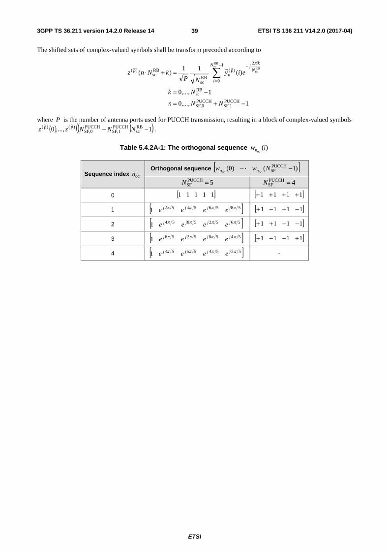
3GPP TS 36.211 version 14.2.0 Release 14 ETSI TS 136 211 V14.2.0 (2017-04)
ETSI
39
The shifted sets of complex-valued symbols shall be transform precoded according to
1,...,0
1,...,0
)(~11)(
PUCCHSF,1
PUCCHSF,0
RBsc
1
0
2
)~(
RBsc
RBsc
)~(
RBsc
RBsc
−+=
−=
=+⋅ ∑−
=
−
NNn
Nk
eiyNP
kNnzN
i
N
ikj
pn
p
π
where P is the number of antenna ports used for PUCCH transmission, resulting in a block of complex-valued symbols
( ) ( )( )1,...,0 RBsc
PUCCHSF,1
PUCCHSF,0
)~()~( −+ NNNzz pp .
Table 5.4.2A-1: The orthogonal sequence )(oc
iwn
Sequence index ocn Orthogonal sequence [ ])1()0( PUCCH
SFococ−Nww nn L
5PUCCHSF =N 4PUCCH
SF =N
0 [ ]11111 [ ]1111 ++++
1 [ ]585654521 ππππ jjjj eeee [ ]1111 −+−+
2 [ ]565258541 ππππ jjjj eeee [ ]1111 −−++
3 [ ]545852561 ππππ jjjj eeee [ ]1111 +−−+
4 [ ]525456581 ππππ jjjj eeee -

3GPP TS 36.211 version 14.2.0 Release 14 ETSI TS 136 211 V14.2.0 (2017-04)
ETSI
40
5.4.2B PUCCH format 4
The block of bits )1(),...,0( bit −Mbb shall be scrambled with a UE-specific scrambling sequence, resulting in a block
of scrambled bits )1(~
),...,0(~
bit −Mbb according to
( ) 2mod)()()(~
icibib +=
where the scrambling sequence )(ic is given by clause 7.2. The scrambling sequence generator shall be initialised with
⎣ ⎦( ) ( ) RNTI16cell
IDsinit 21212 nNnc +⋅+⋅+= at the start of each subframe where RNTIn is the C-RNTI.
The block of scrambled bits )1(~
),...,0(~
bit −Mbb shall be QPSK modulated as described in Subclause 7.1, resulting in a
block of complex-valued modulation symbols )1(),...,0( symb −Mdd where 2bitsymb MM = .
The block of complex-valued symbols )1(),...,0( symb −Mdd is divided into PUCCH1
PUCCH0 NN + sets, each
corresponding to one SC-FDMA symbol. Transform precoding shall be applied according to
1,...,0
1,...,0
)(1
)(
PUCCH1
PUCCH0
PUCCH4sc
1
0
2
PUCCH4sc
PUCCH4sc
PUCCH4sc
)~(
PUCCH4sc
PUCCH4sc
−+=
−=
+⋅=+⋅ ∑−
=
−
NNl
Mk
eiMldM
kMlzM
i
M
ikj
p
π
where 0~ =p , PUCCH0N and PUCCH
1N are given by Table 5.4.2C-1 for normal PUCCH format 4 and shortened PUCCH
format 4, resulting in a block of complex-valued symbols )1(),...,0( symb)~()~( −Mzz pp . The
variable RBsc
PUCCH4RB
PUCCH4sc NMM ⋅= , where PUCCH4
RBM represents the bandwidth of the PUCCH format 4 in terms of
resource blocks, shall fulfil
ULRB
PUCCH4RB
532 532 NM ≤⋅⋅= ααα
where 532 ,, ααα is a set of non-negative integers.
5.4.2C PUCCH format 5
The block of bits )1(),...,0( bit −Mbb shall be scrambled with a UE-specific scrambling sequence, resulting in a block
of scrambled bits )1(~
),...,0(~
bit −Mbb according to
( ) 2mod)()()(~
icibib +=
where the scrambling sequence )(ic is given by clause 7.2. The scrambling sequence generator shall be initialised with
⎣ ⎦( ) ( ) RNTI16cell
IDsinit 21212 nNnc +⋅+⋅+= at the start of each subframe where RNTIn is the C-RNTI.
The block of scrambled bits )1(~
),...,0(~
bit −Mbb shall be QPSK modulated as described in Subclause 7.1, resulting in a
block of complex-valued modulation symbols )1(),...,0( symb −Mdd where 2bitsymb MM = .
The complex-valued symbols )1(),...,0( symb −Mdd shall be divided into PUCCH1
PUCCH0 NN + sets, each corresponding
to one SC-FDMA symbol. Block-wise spreading shall be applied according to
( ) ( ) ( )
1,...,1,0
1,...,0
mod
RBsc
PUCCH1
PUCCH0
PUCCHSF
RBsc
PUCCHSF
RBscoc
−=
−+=
⋅+⋅=
Ni
NNn
NNnNNidiwiy nn

3GPP TS 36.211 version 14.2.0 Release 14 ETSI TS 136 211 V14.2.0 (2017-04)
ETSI
41
where 2PUCCHSF =N , PUCCH
0N and PUCCH1N are given by Table 5.4.2C-1 for normal PUCCH format 5 and shortened
PUCCH format 5, and ( )iwnoc is given by Table 5.4.2C-2 with ocn provided by higher layers.
The block-wise spread complex-valued symbols shall be transform precoded according to
1,...,0
1,...,0
)(1
)(
PUCCH1
PUCCH0
RBsc
1
0
2
RBsc
RBsc
)~(
RBsc
RBsc
−+=
−=
=+⋅ ∑−
=
−
NNn
Nk
eiyN
kNnzN
i
N
ikj
np
π
where 0~ =p , resulting in a block of complex-valued symbols ( ) ( )( )1,...,0 RBsc
PUCCH1
PUCCH0
)~()~( −+ NNNzz pp .
Table 5.4.2C-1: The quantities PUCCH0N and PUCCH
1N
PUCCH format type Normal cyclic prefix Extended cyclic prefix PUCCH0N
PUCCH1N
PUCCH0N
PUCCH1N
Normal PUCCH format
6 6 5 5
Shortened PUCCH format
6 5 5 4
Table 5.4.2C-2: Orthogonal sequences )(oc
iwn
ocn Orthogonal sequences ( ) ( )[ ]10 −RBscnn Nww
CDMCDML
0 [ ]111111111111 ++++++++++++
1 [ ]111111111111 −−−−−−++++++
5.4.3 Mapping to physical resources
The block of complex-valued symbols )()~( iz p shall be multiplied with the amplitude scaling factor PUCCHβ in order to
conform to the transmit power PUCCHP specified in Subclause 5.1.2.1 in 3GPP TS 36.213 [4], and mapped in sequence
starting with )0()~( pz to resource elements. PUCCH uses one or more resource block in each of the two slots in a
subframe. Within the physical resource block(s) used for transmission, the mapping of )()~( iz p to resource elements
( )lk, on antenna port p and not used for transmission of reference signals shall be in increasing order of first k , then
l and finally the slot number, starting with the first slot in the subframe. The relation between the index p~ and the
antenna port number p is given by Table 5.2.1-1.
For non-BL/CE UEs, except for PUCCH format 4, the physical resource blocks to be used for transmission of PUCCH in slot sn are given by
( )
( )⎪⎪
⎩
⎪⎪
⎨
⎧
=+⎥⎦
⎥⎢⎣
⎢−−
=+⎥⎦
⎥⎢⎣
⎢
=12mod2mod if
21
02mod2mod if2
sULRB
s
PRB
nmm
N
nmm
n
For BL/CE UEs, PUCCH is transmitted with 1PUCCHrep ≥N repetitions. The PUCCH transmission spans
PUCCHrep
PUCCHabs NN ≥ consecutive subframes, including non-BL/CE UL subframes where the UE postpones the PUCCH
transmission if 1PUCCHrep >N . The quantity PUCCH
repN is given by the higher-layer parameter pucch-NumRepetitionCE-

3GPP TS 36.211 version 14.2.0 Release 14 ETSI TS 136 211 V14.2.0 (2017-04)
ETSI
42
Msg4-Level0, pucch-NumRepetitionCE-Msg4-Level1, pucch-NumRepetitionCE-Msg4-Level2 or pucch-NumRepetitionCE-Msg4-Level3 for transmission of Msg4 in the random-access procedure [8], otherwise by pucch-NumRepetitionCE-Format1 for PUCCH format 1/1a and pucch-NumRepetitionCE-Format2 for PUCCH format 2/2a/2b,
The physical resource blocks to be used for transmission of PUCCH in subframe i within the PUCCHabsN consecutive
subframes are given by
( )⎣ ⎦ ( )
1
12mod and 12mod if1
02mod and 12mod if1
02mod if
)(
12mod if2)(1
02mod if2)()(
PUCCHabs00
ULch,NB
ULRB
PRB
−+≤≤
⎥⎥⎦
⎥
⎢⎢⎣
⎢=
⎪⎩
⎪⎨
⎧
==−==+
==′
⎩⎨⎧
=′′−−=′′
=
Niii
N
ij
mjm
mjm
jm
jm
jmjmN
jmjmin
where 0i is the absolute subframe number of the first uplink subframe intended for PUCCH.
The variable m depends on the PUCCH format.
- Formats 1, 1a and 1b:
⎩⎨⎧
=
⎪⎩
⎪⎨
⎧
⎥⎥⎥
⎤
⎢⎢⎢
⎡++
⎥⎥⎦
⎥
⎢⎢⎣
⎢
Δ⋅Δ⋅−
Δ⋅<=
prefix cyclic extended2
prefix cyclic normal3
otherwise8
if(1)cs(2)
RBPUCCHshift
RBsc
PUCCHshift
(1)cs
)~(1,PUCCH
PUCCHshift
(1)cs
)~(1,PUCCH
(2)RB
c
NN
Nc
Ncn
NcnN
m p
p
- Formats 2, 2a and 2b:
⎣ ⎦RBsc
)~(2,PUCCH Nnm p=
- Format 3:
⎣ ⎦PUCCHSF,0
)~(3,PUCCH Nnm p=
- Format 5 (non-BL/CE UEs only):
)5(PUCCHnm =
For non-BL/CE UEs, for PUCCH format 4, the physical resource blocks to be used for transmission of PUCCH in slot
sn are given by
1,...,1,
12mod if1
02mod if
PUCCH4RB
(4)PUCCH
(4)PUCCH
(4)PUCCH
sULRB
sPRB
−++=⎩⎨⎧
=−−=
=
Mnnnm
nmN
nmn
where PUCCH4RBM is obtained from [4].
Mapping of modulation symbols for the physical uplink control channel for PUCCH formats 1 – 3 is illustrated in Figure 5.4.3-1.
In case of simultaneous transmission of sounding reference signal and PUCCH format 1, 1a, 1b, 3, 4 or 5 when there is one serving cell configured, the shortened PUCCH format shall be used where the last SC-FDMA symbol in the second slot of a subframe shall be left empty.
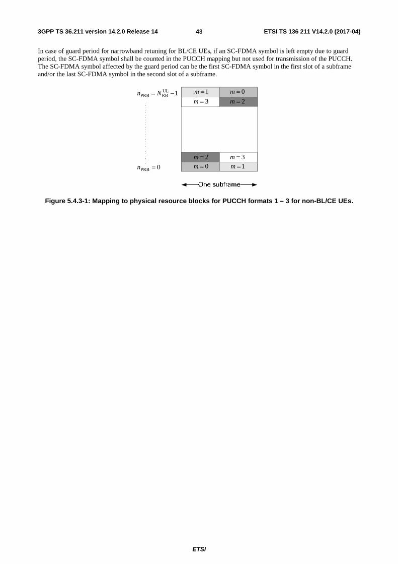
3GPP TS 36.211 version 14.2.0 Release 14 ETSI TS 136 211 V14.2.0 (2017-04)
ETSI
43
In case of guard period for narrowband retuning for BL/CE UEs, if an SC-FDMA symbol is left empty due to guard period, the SC-FDMA symbol shall be counted in the PUCCH mapping but not used for transmission of the PUCCH. The SC-FDMA symbol affected by the guard period can be the first SC-FDMA symbol in the first slot of a subframe and/or the last SC-FDMA symbol in the second slot of a subframe.
0=m
0=m1=m
1=m
2=m
2=m3=m
3=m
0PRB =n
1ULRBPRB −= Nn
Figure 5.4.3-1: Mapping to physical resource blocks for PUCCH formats 1 – 3 for non-BL/CE UEs.
3GPP TS 36.211 version 14.2.0 Release 14 ETSI TS 136 211 V14.2.0 (2017-04)
ETSI
44
5.5 Reference signals Two types of uplink reference signals are supported:
- Demodulation reference signal, associated with transmission of PUSCH or PUCCH
- Sounding reference signal, not associated with transmission of PUSCH or PUCCH
The same set of base sequences is used for demodulation and sounding reference signals.
5.5.1 Generation of the reference signal sequence
Reference signal sequence )(),(, nr vu
δα is defined by a cyclic shift α of a base sequence )(, nr vu according to
RSsc,
2
2mod),(
, 0),()( Mnnrenr vu
nj
vu <≤=⎟⎠
⎞⎜⎝
⎛ + ϖδαδα
where δ2RBsc
RSsc mNM = is the length of the reference signal sequence, ULmax,
RB1 Nm ≤≤ , ϖ is defined in subclause
5.5.2.1.2, and the quantity 1=δ when the higher-layer parameter ul-DMRS-IFDMA is set for demodulation reference signal associated with PUSCH transmission, and 0=δ otherwise. Multiple reference signal sequences are defined from a single base sequence through different values of α .
Base sequences )(, nr vu are divided into groups, where { }29,...,1,0∈u is the group number and v is the base sequence
number within the group, such that each group contains one base sequence ( 0=v ) of each length RBsc
RSsc mNM = ,
51 ≤≤ m and two base sequences ( 1,0=v ) of each length RBsc
RSsc mNM = , ULmax,
RB6 Nm ≤≤ . The sequence group
number u and the number v within the group may vary in time as described in clauses 5.5.1.3 and 5.5.1.4,
respectively. The definition of the base sequence )1(),...,0( RSsc,, −Mrr vuvu depends on the sequence length RS
scM .
5.5.1.1 Base sequences of length RBsc3N or larger
For RBsc
RSsc 3NM ≥ , the base sequence )1(),...,0( RS
sc,, −Mrr vuvu is given by
RSsc
RSZC, 0),mod()( MnNnxnr qvu <≤=
where the thq root Zadoff-Chu sequence is defined by
( ) 10, RSZC
)1(RSZC −≤≤=
+−Nmemx N
mqmj
q
π
with q given by
⎣ ⎦ ⎣ ⎦
31)1(
)1(21RSZC
2
+⋅=
−⋅++=
uNq
vqq q
The length RSZCN of the Zadoff-Chu sequence is given by the largest prime number such that RS
scRSZC MN < .

3GPP TS 36.211 version 14.2.0 Release 14 ETSI TS 136 211 V14.2.0 (2017-04)
ETSI
45
5.5.1.2 Base sequences of length less than RBsc3N
For RBsc
RSsc NM = , RB
scRSsc 2NM = , 2RB
scRSsc NM = , and 23 RB
scRSsc NM = , the base sequence is given by
10,)( RSsc
4)(, −≤≤= Mnenr njvu
πϕ
where the value of )(nϕ is given by Table 5.5.1.2-1, Table 5.5.1.2-2, Table 5.5.1.2-3, and Table 5.5.1.2-4 for RBsc
RSsc NM = , RB
scRSsc 2NM = , 2RB
scRSsc NM = , and 23 RB
scRSsc NM = , respectively. For 25 RB
scRSsc NM = , the base
sequence )1(),...,0( RSsc,, −Mrr vuvu is given by
( ) 10, RSsc
31
)2)(1)(1(
, −≤≤=+++−
Mnenrnnu
j
vu
π
Table 5.5.1.2-1: Definition of )(nϕ for RBsc
RSsc NM = .
u )11(),...,0( ϕϕ
0 -1 1 3 -3 3 3 1 1 3 1 -3 3 1 1 1 3 3 3 -1 1 -3 -3 1 -3 3 2 1 1 -3 -3 -3 -1 -3 -3 1 -3 1 -1 3 -1 1 1 1 1 -1 -3 -3 1 -3 3 -1 4 -1 3 1 -1 1 -1 -3 -1 1 -1 1 3 5 1 -3 3 -1 -1 1 1 -1 -1 3 -3 1 6 -1 3 -3 -3 -3 3 1 -1 3 3 -3 1 7 -3 -1 -1 -1 1 -3 3 -1 1 -3 3 1 8 1 -3 3 1 -1 -1 -1 1 1 3 -1 1 9 1 -3 -1 3 3 -1 -3 1 1 1 1 1
10 -1 3 -1 1 1 -3 -3 -1 -3 -3 3 -1 11 3 1 -1 -1 3 3 -3 1 3 1 3 3 12 1 -3 1 1 -3 1 1 1 -3 -3 -3 1 13 3 3 -3 3 -3 1 1 3 -1 -3 3 3 14 -3 1 -1 -3 -1 3 1 3 3 3 -1 1 15 3 -1 1 -3 -1 -1 1 1 3 1 -1 -3 16 1 3 1 -1 1 3 3 3 -1 -1 3 -1 17 -3 1 1 3 -3 3 -3 -3 3 1 3 -1 18 -3 3 1 1 -3 1 -3 -3 -1 -1 1 -3 19 -1 3 1 3 1 -1 -1 3 -3 -1 -3 -1 20 -1 -3 1 1 1 1 3 1 -1 1 -3 -1 21 -1 3 -1 1 -3 -3 -3 -3 -3 1 -1 -3 22 1 1 -3 -3 -3 -3 -1 3 -3 1 -3 3 23 1 1 -1 -3 -1 -3 1 -1 1 3 -1 1 24 1 1 3 1 3 3 -1 1 -1 -3 -3 1 25 1 -3 3 3 1 3 3 1 -3 -1 -1 3 26 1 3 -3 -3 3 -3 1 -1 -1 3 -1 -3 27 -3 -1 -3 -1 -3 3 1 -1 1 3 -3 -3 28 -1 3 -3 3 -1 3 3 -3 3 3 -1 -1 29 3 -3 -3 -1 -1 -3 -1 3 -3 3 1 -1

3GPP TS 36.211 version 14.2.0 Release 14 ETSI TS 136 211 V14.2.0 (2017-04)
ETSI
46
Table 5.5.1.2-2: Definition of )(nϕ for RBsc
RSsc 2NM =
u )23(),...,0( ϕϕ
0 -1 3 1 -3 3 -1 1 3 -3 3 1 3 -3 3 1 1 -1 1 3 -3 3 -3 -1 -3 1 -3 3 -3 -3 -3 1 -3 -3 3 -1 1 1 1 3 1 -1 3 -3 -3 1 3 1 1 -3 2 3 -1 3 3 1 1 -3 3 3 3 3 1 -1 3 -1 1 1 -1 -3 -1 -1 1 3 3 3 -1 -3 1 1 3 -3 1 1 -3 -1 -1 1 3 1 3 1 -1 3 1 1 -3 -1 -3 -1 4 -1 -1 -1 -3 -3 -1 1 1 3 3 -1 3 -1 1 -1 -3 1 -1 -3 -3 1 -3 -1 -1 5 -3 1 1 3 -1 1 3 1 -3 1 -3 1 1 -1 -1 3 -1 -3 3 -3 -3 -3 1 1 6 1 1 -1 -1 3 -3 -3 3 -3 1 -1 -1 1 -1 1 1 -1 -3 -1 1 -1 3 -1 -3 7 -3 3 3 -1 -1 -3 -1 3 1 3 1 3 1 1 -1 3 1 -1 1 3 -3 -1 -1 1 8 -3 1 3 -3 1 -1 -3 3 -3 3 -1 -1 -1 -1 1 -3 -3 -3 1 -3 -3 -3 1 -3 9 1 1 -3 3 3 -1 -3 -1 3 -3 3 3 3 -1 1 1 -3 1 -1 1 1 -3 1 1
10 -1 1 -3 -3 3 -1 3 -1 -1 -3 -3 -3 -1 -3 -3 1 -1 1 3 3 -1 1 -1 3 11 1 3 3 -3 -3 1 3 1 -1 -3 -3 -3 3 3 -3 3 3 -1 -3 3 -1 1 -3 1 12 1 3 3 1 1 1 -1 -1 1 -3 3 -1 1 1 -3 3 3 -1 -3 3 -3 -1 -3 -1 13 3 -1 -1 -1 -1 -3 -1 3 3 1 -1 1 3 3 3 -1 1 1 -3 1 3 -1 -3 3 14 -3 -3 3 1 3 1 -3 3 1 3 1 1 3 3 -1 -1 -3 1 -3 -1 3 1 1 3 15 -1 -1 1 -3 1 3 -3 1 -1 -3 -1 3 1 3 1 -1 -3 -3 -1 -1 -3 -3 -3 -1 16 -1 -3 3 -1 -1 -1 -1 1 1 -3 3 1 3 3 1 -1 1 -3 1 -3 1 1 -3 -1 17 1 3 -1 3 3 -1 -3 1 -1 -3 3 3 3 -1 1 1 3 -1 -3 -1 3 -1 -1 -1 18 1 1 1 1 1 -1 3 -1 -3 1 1 3 -3 1 -3 -1 1 1 -3 -3 3 1 1 -3 19 1 3 3 1 -1 -3 3 -1 3 3 3 -3 1 -1 1 -1 -3 -1 1 3 -1 3 -3 -3 20 -1 -3 3 -3 -3 -3 -1 -1 -3 -1 -3 3 1 3 -3 -1 3 -1 1 -1 3 -3 1 -1 21 -3 -3 1 1 -1 1 -1 1 -1 3 1 -3 -1 1 -1 1 -1 -1 3 3 -3 -1 1 -3 22 -3 -1 -3 3 1 -1 -3 -1 -3 -3 3 -3 3 -3 -1 1 3 1 -3 1 3 3 -1 -3 23 -1 -1 -1 -1 3 3 3 1 3 3 -3 1 3 -1 3 -1 3 3 -3 3 1 -1 3 3 24 1 -1 3 3 -1 -3 3 -3 -1 -1 3 -1 3 -1 -1 1 1 1 1 -1 -1 -3 -1 3 25 1 -1 1 -1 3 -1 3 1 1 -1 -1 -3 1 1 -3 1 3 -3 1 1 -3 -3 -1 -1 26 -3 -1 1 3 1 1 -3 -1 -1 -3 3 -3 3 1 -3 3 -3 1 -1 1 -3 1 1 1 27 -1 -3 3 3 1 1 3 -1 -3 -1 -1 -1 3 1 -3 -3 -1 3 -3 -1 -3 -1 -3 -1 28 -1 -3 -1 -1 1 -3 -1 -1 1 -1 -3 1 1 -3 1 -3 -3 3 1 1 -1 3 -1 -1 29 1 1 -1 -1 -3 -1 3 -1 3 -1 1 3 1 -1 3 1 3 -3 -3 1 -1 -1 1 3

3GPP TS 36.211 version 14.2.0 Release 14 ETSI TS 136 211 V14.2.0 (2017-04)
ETSI
47
Table 5.5.1.2-3: Definition of )(nϕ for 2RBsc
RSsc NM =
u )5(),...,0( ϕϕ
0 -1 -3 3 -3 3 -3 1 -1 3 -1 1 1 1 2 3 -1 -3 -3 1 3 3 3 -1 -1 1 -1 -1 4 -1 -1 -3 1 -3 -1 5 1 3 -3 -1 -3 3 6 -3 3 -1 -1 1 -3 7 -1 -3 -3 1 3 3 8 3 -1 -1 3 1 3 9 3 -3 3 1 -1 1
10 -3 1 -3 -3 -3 -3 11 -3 -3 -3 1 -3 -3 12 3 -3 1 -1 -3 -3 13 3 -3 3 -1 -1 -3 14 3 -1 1 3 3 1 15 -1 1 -1 -3 1 1 16 -3 -1 -3 -1 3 3 17 1 -1 3 -3 3 3 18 1 3 1 1 -3 3 19 -1 -3 -1 -1 3 -3 20 3 -1 -3 -1 -1 -3 21 3 1 3 -3 -3 1 22 1 3 -1 -1 1 -1 23 -3 1 -3 3 3 3 24 1 3 -3 3 -3 3 25 -1 -1 1 -3 1 -1 26 1 -3 -1 -1 3 1 27 -3 -1 -1 3 1 1 28 -1 3 -3 -3 -3 3 29 3 1 -1 1 3 1

3GPP TS 36.211 version 14.2.0 Release 14 ETSI TS 136 211 V14.2.0 (2017-04)
ETSI
48
Table 5.5.1.2-4: Definition of )(nϕ for 23 RBsc
RSsc NM =
u )17(),...,0( ϕϕ 0 -3 -3 -3 -3 -3 -1 1 -1 -3 3 -1 3 -1 3 -3 -1 -1 3 1 -3 -3 -3 -3 -3 -1 1 -1 1 -3 -3 -3 1 -1 3 -3 -3 1 2 -3 -3 -3 -3 -3 -1 1 1 3 -3 1 1 -3 1 -3 3 1 -1 3 -3 -3 -3 -3 -3 -1 1 3 -3 -1 3 -1 3 1 -1 -3 3 -3 4 -3 -3 -3 -3 -3 -1 3 -3 -1 1 -1 -3 3 3 1 -3 1 -1 5 -3 -3 -3 -3 -3 1 -3 -3 -3 -3 1 1 1 -3 1 1 -3 -3 6 -3 -3 -3 -3 -3 1 -3 -3 1 1 -3 -3 -3 1 -1 3 -1 3 7 -3 -3 -3 -3 -3 1 -3 -1 3 -1 3 3 -1 -1 1 3 3 -1 8 -3 -3 -3 -3 -3 1 -1 -1 -1 -3 3 -1 3 -3 3 -1 1 3 9 -3 -3 -3 -3 -3 3 -3 1 -1 3 -3 3 3 -1 -3 1 1 -3
10 -3 -3 -3 -3 -3 3 -1 -3 -3 1 1 3 -3 -1 3 -1 3 1 11 -3 -3 -3 -3 -3 3 3 -1 -1 -1 3 1 -3 3 -1 1 -3 1 12 -3 -3 -3 -3 -1 -3 -3 -3 1 3 1 -1 3 -3 -1 -3 1 1 13 -3 -3 -3 -3 -1 -3 -3 1 -1 -1 3 -3 -3 1 3 1 -3 1 14 -3 -3 -3 -3 -1 -3 -3 1 3 -3 -1 3 1 3 -1 3 -1 -3 15 -3 -3 -3 -3 -1 -3 -1 3 -3 1 -3 1 -1 -3 -3 1 1 3 16 -3 -3 -3 -3 -1 -1 3 -3 3 -1 -3 1 1 -1 -3 -1 3 -3 17 -3 -3 -3 -3 -1 -1 3 -1 -3 1 3 -1 -3 -3 1 3 -1 1 18 -3 -3 -3 -3 -1 3 -1 -1 3 3 -1 -3 1 1 1 -1 -3 -1 19 -3 -3 -3 -3 -1 3 1 -3 -1 -3 3 1 -1 3 -1 1 3 -1 20 -3 -3 -3 -3 1 -3 -3 3 1 1 -3 -1 1 3 3 -1 3 -1 21 -3 -3 -3 -3 1 -3 1 3 1 -1 -1 3 3 -1 1 1 -3 3 22 -3 -3 -3 -3 1 -3 3 -3 -1 3 1 1 -1 -1 3 3 -1 3 23 -3 -3 -3 -3 1 -3 3 -1 3 -3 -1 -1 -1 1 -3 -3 3 1 24 -3 -3 -3 -3 1 1 3 1 1 -1 3 1 1 3 -1 -3 1 3 25 -3 -3 -3 -3 1 3 3 3 1 -3 1 -3 -3 3 -3 1 -1 -3 26 -3 -3 -3 -3 3 1 3 3 -1 3 -3 -3 -1 3 -1 -1 -3 1 27 -3 -3 -3 -1 -3 -3 -1 -1 -3 3 3 1 -3 -1 -1 3 1 -3 28 -3 -3 -3 -1 -3 1 -1 1 -3 3 1 -3 -1 1 3 1 -1 -1 29 -3 -3 -3 -1 -3 3 1 1 -1 -1 1 3 1 -3 1 -3 -1 1

3GPP TS 36.211 version 14.2.0 Release 14 ETSI TS 136 211 V14.2.0 (2017-04)
ETSI
49
5.5.1.3 Group hopping
The sequence-group number u in slot sn is defined by a group hopping pattern )( sgh nf and a sequence-shift pattern
ssf according to
( ) 30mod)( sssgh fnfu +=
There are 17 different hopping patterns and 30 different sequence-shift patterns. Sequence-group hopping can be enabled or disabled by means of the cell-specific parameter Group-hopping-enabled provided by higher layers. Sequence-group hopping for PUSCH can be disabled for a certain UE through the higher-layer parameter Disable-sequence-group-hopping despite being enabled on a cell basis unless the PUSCH transmission corresponds to a Random Access Response Grant or a retransmission of the same transport block as part of the contention based random access procedure.
The group-hopping pattern )( sgh nf may be different for PUSCH, PUCCH and SRS and is given by
⎪⎩
⎪⎨⎧
⎟⎠⎞
⎜⎝⎛ ⋅+=∑ = enabled is hopping group if30mod2)8(
disabled is hopping group if0)( 7
0 ssgh
iiinc
nf
where the pseudo-random sequence )(ic is defined by clause 7.2. The pseudo-random sequence generator shall be
initialized with ⎥⎥⎦
⎥
⎢⎢⎣
⎢=
30
RSID
initn
c at the beginning of each radio frame where RSIDn is given by clause 5.5.1.5.
The sequence-shift pattern ssf definition differs between PUCCH, PUSCH and SRS.
For PUCCH, the sequence-shift pattern PUCCHssf is given by 30modRS
IDPUCCH
ss nf = where RSIDn is given by clause
5.5.1.5.
For PUSCH, the sequence-shift pattern PUSCHssf is given by ( ) 30modss
cellID
PUSCHss Δ+= Nf , where { }29,...,1,0ss ∈Δ is
configured by higher layers, if no value for PUSCHIDn is provided by higher layers or if the PUSCH transmission
corresponds to a Random Access Response Grant or a retransmission of the same transport block as part of the
contention based random access procedure, otherwise it is given by 30modRSID
PUSCHss nf = with RS
IDn given by clause
5.5.1.5.
For SRS, the sequence-shift pattern SRSssf is given by 30modRS
IDSRS
ss nf = where RSIDn is given by clause 5.5.1.5.
3GPP TS 36.211 version 14.2.0 Release 14 ETSI TS 136 211 V14.2.0 (2017-04)
ETSI
50
5.5.1.4 Sequence hopping
Sequence hopping only applies for reference-signals of length RBsc
RSsc 6NM ≥ .
For reference-signals of length RBsc
RSsc 6NM < , the base sequence number v within the base sequence group is given by
0=v .
For reference-signals of length RBsc
RSsc 6NM ≥ , the base sequence number v within the base sequence group in slot sn
is defined by
⎩⎨⎧
=otherwise0
enabled is hopping sequence and disabled is hopping group if)( sncv
where the pseudo-random sequence )(ic is given by clause 7.2. The parameter Sequence-hopping-enabled provided by
higher layers determines if sequence hopping is enabled or not. Sequence hopping for PUSCH can be disabled for a certain UE through the higher-layer parameter Disable-sequence-group-hopping despite being enabled on a cell basis unless the PUSCH transmission corresponds to a Random Access Response Grant or a retransmission of the same transport block as part of the contention based random access procedure.
For PUSCH or PUCCH format 4 transmission with ≥ 6 RBs, the pseudo-random sequence generator shall be initialized
with PUSCHss
5RSID
init 230
fn
c +⋅⎥⎥⎦
⎥
⎢⎢⎣
⎢= at the beginning of each radio frame where RS
IDn is given by clause 5.5.1.5.
For SRS, the pseudo-random sequence generator shall be initialized with ( ) 30mod230 ss
RSID
5RSID
init Δ++⋅⎥⎥⎦
⎥
⎢⎢⎣
⎢= n
nc at the
beginning of each radio frame where RSIDn is given by clause 5.5.1.5 and ssΔ is given by clause 5.5.1.3.
5.5.1.5 Determining virtual cell identity for sequence generation
The definition of RSIDn depends on the type of transmission.
Transmissions associated with PUSCH:
- cellID
RSID Nn = if no value for PUSCH
IDn is configured by higher layers or if the PUSCH transmission corresponds to
a Random Access Response Grant or a retransmission of the same transport block as part of the contention based random access procedure,
- PUSCHID
RSID nn = otherwise.
Transmissions associated with PUCCH:
- cellID
RSID Nn = if no value for PUCCH
IDn is configured by higher layers,
- PUCCHID
RSID nn = otherwise.
Sounding reference signals:
- cellID
RSID Nn = .

3GPP TS 36.211 version 14.2.0 Release 14 ETSI TS 136 211 V14.2.0 (2017-04)
ETSI
51
5.5.2 Demodulation reference signal
5.5.2.1 Demodulation reference signal for PUSCH
5.5.2.1.1 Reference signal sequence
The PUSCH demodulation reference signal sequence ( )⋅)(PUSCH
λr associated with layer { }1,...,1,0 −∈ υλ is defined by
( ) ( )nrmwnMmr vu),(
,)(RS
sc)(
PUSCH )( δαλλ λ=+⋅
where
1,...,0
otherwise1,0
subframe specialfor 0
RSsc −=
⎩⎨⎧
=
Mn
m
and 2PUSCHsc
RSsc MM = if the higher-layer parameter ul-DMRS-IFDMA is set and PUSCH
scRSsc MM = otherwise.
Subclause 5.5.1 defines the sequence )1(),...,0( RSsc
),(,
),(, −Mrr vuvu
δαδα λλ where, for PUSCH demodulation reference signal
sequence, 1=δ when the higher-layer parameter ul-DMRS-IFDMA is set, and 0=δ otherwise. The orthogonal
sequence )()( mw λ is given by [ ] [ ]11)1()0( =λλ ww for DCI format 0 if the higher-layer parameter Activate-DMRS-
with OCC is not set or if the temporary C-RNTI was used to transmit the most recent uplink-related DCI for the transport block associated with the corresponding PUSCH transmission. Otherwise,
- if higher-layer parameter ul-DMRS-IFDMA is not set, )()( mw λ is given by Table 5.5.2.1.1-1 using the cyclic
shift field in the most recent uplink-related DCI [3],
- if higher-layer parameter ul-DMRS-IFDMA is set and the Cyclic Shift Field mapping table for DMRS bit field is
not present in the most recent uplink-related DCI, )()( mw λ is given by Table 5.5.2.1.1-1 using the cyclic shift
field in the most recent uplink-related DCI,
- if higher-layer parameter ul-DMRS-IFDMA is set and the Cyclic Shift Field mapping table for DMRS bit field is
present in the most recent uplink-related DCI, )()( mw λ is given by Table 5.5.2.1.1-1 using the cyclic shift field
in the most recent uplink-related DCI when the Cyclic Shift Field mapping table for DMRS bit field indicates the use of Table 5.5.2.1.1-1, and
- if higher-layer parameter ul-DMRS-IFDMA is set and the Cyclic Shift Field mapping table for DMRS bit field is
present in the most recent uplink-related DCI, )()( mw λ is given by Table 5.5.2.1.1-3 using the cyclic shift field
in the most recent uplink-related DCI when the Cyclic Shift Field mapping table for DMRS bit field indicates the use of Table 5.5.2.1.1-3.
The cyclic shift λα in a slot sn is given as 0=λα if the ul-V-SPS-RNTI-r14 was used to transmit the most recent
uplink-related DCI for the transport block associated with the corresponding PUSCH transmission. Otherwise, the cyclic shift λα in a slot sn is given as 122 cs,λλ πα n= with
( ) 12mod)()1( sPN)2(
DMRS,)1(
DMRScs, nnnnn δλλ +++=
where the value of (1)DMRSn is given by Table 5.5.2.1.1-2 according to the parameter cyclicShift provided by higher
layers. For non-BL/CE UEs (2)DMRS,λn is given using the most recent uplink-related DCI 3GPP TS 36.212 [3] for the
transport block associated with the corresponding PUSCH transmission as follows:
- if the higher-layer parameter ul-DMRS-IFDMA is not set, (2)DMRS,λn is given by Table 5.5.2.1.1-1 using the cyclic
shift field in the most recent uplink-related DCI,

3GPP TS 36.211 version 14.2.0 Release 14 ETSI TS 136 211 V14.2.0 (2017-04)
ETSI
52
- if higher-layer parameter ul-DMRS-IFDMA is set and the Cyclic Shift Field mapping table for DMRS bit field is
not present in the most recent uplink-related DCI, (2)DMRS,λn is given by Table 5.5.2.1.1-1 using the cyclic shift
field in the most recent uplink-related DCI,
- if higher-layer parameter ul-DMRS-IFDMA is set and the Cyclic Shift Field mapping table for DMRS bit field is
present in the most recent uplink-related DCI, (2)DMRS,λn is given by Table 5.5.2.1.1-1 using the cyclic shift field
in the most recent uplink-related DCI when the Cyclic Shift Field mapping table for DMRS bit field indicates the use of Table 5.5.2.1.1-1, and
- if higher-layer parameter ul-DMRS-IFDMA is set and the Cyclic Shift Field mapping table for DMRS bit field is
present in the most recent uplink-related DCI, (2)DMRS,λn is given by Table 5.5.2.1.1-3 using the cyclic shift field
in the most recent uplink-related DCI when the Cyclic Shift Field mapping table for DMRS bit field indicates the use of Table 5.5.2.1.1-3.
The first row of Table 5.5.2.1.1-1 shall be used to obtain (2)0DMRS,n and )()( mw λ if there is no uplink-related DCI for the
same transport block associated with the corresponding PUSCH transmission, and
- if the initial PUSCH for the same transport block is semi-persistently scheduled, or
- if the initial PUSCH for the same transport block is scheduled by the random access response grant.
The quantity )( sPN nn is given by
∑ =⋅+⋅=
7
0 sULsymbsPN 2)8()(
i
iinNcnn
where the pseudo-random sequence )(ic is defined by clause 7.2. The application of )(ic is cell-specific. The pseudo-
random sequence generator shall be initialized with initc at the beginning of each radio frame. The quantity initc is
given by ( )( )30mod230 ss
cellID
5cellID
init Δ++⋅⎥⎥⎦
⎥
⎢⎢⎣
⎢= N
Nc if no value for csh_DMRS
IDN is configured by higher layers for
PUSCH/PUCCH format 4/PUCCH format 5 or the PUSCH transmission corresponds to a Random Access Response Grant or a retransmission of the same transport block as part of the contention based random access procedure,
otherwise it is given by ( )30mod230
csh_DMRSID
5csh_DMRSID
init NN
c +⋅⎥⎥⎦
⎥
⎢⎢⎣
⎢= .
The vector of reference signals shall be precoded according to
⎥⎥⎥
⎦
⎤
⎢⎢⎢
⎣
⎡
=⎥⎥⎥
⎦
⎤
⎢⎢⎢
⎣
⎡
−− )1(PUSCH
)0(PUSCH
)1(PUSCH
)0(PUSCH
~
~
υr
r
W
r
r
P
MM
where P is the number of antenna ports used for PUSCH transmission.
For PUSCH transmission using a single antenna port, 1=P , 1=W and 1=υ .
For spatial multiplexing, 2=P or 4=P and the precoding matrix W shall be identical to the precoding matrix used in clause 5.3.3A.2 for precoding of the PUSCH in the same subframe.
Table 5.5.2.1.1-1: Mapping of Cyclic Shift Field in uplink-related DCI format to (2)DMRS,λn and
[ ])1()0( )()( λλ ww
Cyclic Shift Field in uplink-related DCI format [3]
(2)DMRS,λn [ ])1()0( )()( λλ ww
0=λ 1=λ 2=λ 3=λ 0=λ 1=λ 2=λ 3=λ

3GPP TS 36.211 version 14.2.0 Release 14 ETSI TS 136 211 V14.2.0 (2017-04)
ETSI
53
000 0 6 3 9 [ ]11 [ ]11 [ ]11 − [ ]11 −
001 6 0 9 3 [ ]11 − [ ]11 − [ ]11 [ ]11
010 3 9 6 0 [ ]11 − [ ]11 − [ ]11 [ ]11
011 4 10 7 1 [ ]11 [ ]11 [ ]11 [ ]11
100 2 8 5 11 [ ]11 [ ]11 [ ]11 [ ]11
101 8 2 11 5 [ ]11 − [ ]11 − [ ]11 − [ ]11 −
110 10 4 1 7 [ ]11 − [ ]11 − [ ]11 − [ ]11 −
111 9 3 0 6 [ ]11 [ ]11 [ ]11 − [ ]11 −
Table 5.5.2.1.1-2: Mapping of cyclicShift to (1)DMRSn values
cyclicShift (1)DMRSn
0 0 1 2 2 3 3 4 4 6 5 8 6 9 7 10
Table 5.5.2.1.1-3: Mapping of Cyclic Shift Field in uplink-related DCI format to (2)DMRS,λn , ϖ , and
[ ])1()0( )()( λλ ww
Cyclic Shift Field in uplink-related DCI format [3]
ϖ (2)DMRS,λn [ ])1()0( )()( λλ ww
0=λ 1=λ 2=λ 3=λ 0=λ 1=λ 2=λ 3=λ
000 1 0 6 3 9 [ ]11 [ ]11 [ ]11 − [ ]11 −
001 1 6 0 9 3 [ ]11 − [ ]11 − [ ]11 [ ]11
010 1 3 9 6 0 [ ]11 − [ ]11 − [ ]11 [ ]11
011 0 4 10 7 1 [ ]11 [ ]11 [ ]11 [ ]11
100 0 2 8 5 11 [ ]11 [ ]11 [ ]11 [ ]11
101 0 8 2 11 5 [ ]11 − [ ]11 − [ ]11 − [ ]11 −
110 0 10 4 1 7 [ ]11 − [ ]11 − [ ]11 − [ ]11 −
111 1 9 3 0 6 [ ]11 [ ]11 [ ]11 − [ ]11 −
5.5.2.1.2 Mapping to physical resources
For each antenna port used for transmission of the PUSCH, the sequence ( )⋅)~(PUSCH
~ pr shall be multiplied with the
amplitude scaling factor PUSCHβ and mapped in sequence starting with ( )0~ )~(PUSCH
pr to the resource blocks.
If higher-layer parameter ul-DMRS-IFDMA is set and the most recent uplink-related DCI contains the Cyclic Shift Field mapping table for DMRS bit field which indicates the use of Table 5.5.2.1.1-3, the mapping to resource elements ),( lk ,
with 3=l for normal cyclic prefix and 2=l for extended cyclic prefix, in the subframe shall be in increasing order of first k for all values of k satisfying ϖ=2modk , then the slot number. The quantity ϖ is given by Table 5.5.2.1.1-3 using the cyclic shift field in the most recent uplink-related DCI.

3GPP TS 36.211 version 14.2.0 Release 14 ETSI TS 136 211 V14.2.0 (2017-04)
ETSI
54
For all other cases, the set of physical resource blocks used in the mapping process and the relation between the index p~ and the antenna port number p shall be identical to the corresponding PUSCH transmission as defined in clause
5.3.4.
The mapping to resource elements ),( lk , with 3=l for normal cyclic prefix and 2=l for extended cyclic prefix, in
the subframe shall be in increasing order of first k , then the slot number. No DM-RS shall be transmitted in UpPTS if dmrsLess-UpPts is set to true.
5.5.2.2 Demodulation reference signal for PUCCH
5.5.2.2.1 Reference signal sequence
The PUCCH demodulation reference signal sequence ( )⋅)~(PUCCH
pr for PUCCH formats 1, 1a, 1b, 2, 2a, 2b, and 3 is
defined by
( ) ( )nrmzmwP
nmMMNmr pvu
pp ),(,
)~(RSsc
RSsc
PUCCHRS
)~(PUCCH
~)()(
1'
δα=++
where
1,0'
1,...,0
1,...,0RSsc
PUCCHRS
=−=
−=
m
Mn
Nm
and P is the number of antenna ports used for PUCCH transmission. For PUCCH formats 2a and 2b, )(mz equals
)10(d for 1=m , where )10(d is defined in clause 5.4.2. For all other cases, .1)( =mz
The sequence )()(
,~
nr pvu
αis given by clause 5.5.1 with 12RS
sc =M and 0=δ where the expression for the cyclic shift p~α
is determined by the PUCCH format.
For PUCCH formats 1, 1a and 1b, ),( s~ lnpα is given by
⎣ ⎦
( )( )[ ]( )[ ]⎪
⎩
⎪⎨
⎧
′+Δ⋅′+
′Δ+Δ⋅′+=
⋅=
′Δ⋅′=
prefix cyclic extendedfor modmod)()(),(
prefix cyclic normalfor modmodmod)()(),(),(
),(2),(
)()(
RBscs
)~(oc
PUCCHshifts~s
cellcs
RBsc
PUCCHshifts
)~(oc
PUCCHshifts~s
cellcs
s)~(
cs
RBscs
)~(css~
PUCCHshifts~s
)~(oc
NNnnnnlnn
NNnnnnlnnlnn
Nlnnln
Nnnnn
pp
ppp
pp
pp
πα
where )( s~ nnp′ , N ′ , PUCCHshiftΔ and ),(cell
cs lnn s are defined by clause 5.4.1. The number of reference symbols per slot
PUCCHRSN and the sequence )(nw are given by Table 5.5.2.2.1-1 and 5.5.2.2.1-2, respectively.
For PUCCH formats 2, 2a and 2b, ),( s~ lnpα is defined by clause 5.4.2. The number of reference symbols per slot
PUCCHRSN and the sequence )()~( nw p are given by Table 5.5.2.2.1-1 and 5.5.2.2.1-3, respectively.
For PUCCH format 3, ),( s~ lnpα is given by
( ) RBscs~s
cellcss
)~(cs
RBscs
)~(css~
mod)(),(),(
),(2),(
Nnnlnnlnn
Nlnnln
pp
pp
′+=
⋅= πα

3GPP TS 36.211 version 14.2.0 Release 14 ETSI TS 136 211 V14.2.0 (2017-04)
ETSI
55
where )( s~ nn p′ is given by Table 5.5.2.2.1-4 and )~(0oc,
pn and )~(1oc,
pn for the first and second slot in a subframe,
respectively, are obtained from clause 5.4.2A. The number of reference symbols per slot PUCCHRSN and the sequence
)(nw are given by Table 5.5.2.2.1-1 and 5.5.2.2.1-3, respectively.
Table 5.5.2.2.1-1: Number of PUCCH demodulation reference symbols per slot PUCCHRSN
PUCCH format Normal cyclic prefix Extended cyclic prefix 1, 1a, 1b 3 2
2, 3 2 1 2a, 2b 2 N/A
Table 5.5.2.2.1-2: Orthogonal sequences [ ])1()0( PUCCHRS
)~()~( −Nww ppL for PUCCH formats 1, 1a and
1b
Sequence index )( s)~(
oc nn p Normal cyclic prefix Extended cyclic prefix
0 [ ]111 [ ]11
1 [ ]34321 ππ jj ee [ ]11 −
2 [ ]32341 ππ jj ee N/A
Table 5.5.2.2.1-3: Orthogonal sequences [ ])1()0( PUCCHRS
)~()~( −Nww ppL for PUCCH formats 2, 2a, 2b
and 3.
Normal cyclic prefix Extended cyclic prefix
[ ]11 [ ]1
Table 5.5.2.2.1-4: Relation between )~(oc
pn and )( s~ nn p′ for PUCCH format 3.
)~(oc
pn )( s~ nn p′
51,SF =N
41,SF =N
0 0 0 1 3 3 2 6 6 3 8 9 4 10 N/A
The PUCCH demodulation reference signal sequence ( )⋅)~(PUCCH
pr for PUCCH formats 4 and 5 is defined by
( ) ( )nrnMmr vup ),(
,RSsc
)~(PUCCH
δα=+⋅
where
1,...,0
1,0
0~
RSsc −=
==
Mn
m
p
and
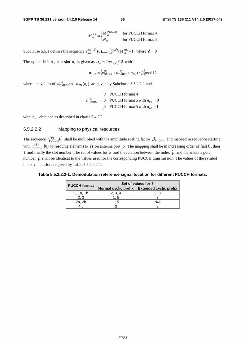
3GPP TS 36.211 version 14.2.0 Release 14 ETSI TS 136 211 V14.2.0 (2017-04)
ETSI
56
⎪⎩
⎪⎨⎧
=5format PUCCHfor
4format PUCCHfor RBsc
PUCCH4scRS
scN
MM
Subclause 5.5.1 defines the sequence )1(),...,0( RSsc
),(,
),(, −Mrr vuvu
δαδα λλ where 0=δ .
The cyclic shift λα in a slot sn is given as 122 cs,λλ πα n= with
( ) 12mod)( sPN)2(
DMRS)1(
DMRScs, nnnnn ++=λ
where the values of (1)DMRSn and )( sPN nn are given by Subclause 5.5.2.1.1 and
⎪⎩
⎪⎨
⎧
===
1 with 5format PUCCH6
0 with 5format PUCCH0
4format PUCCH0
oc
oc(2)DMRS
n
nn
with ocn obtained as described in clause 5.4.2C.
5.5.2.2.2 Mapping to physical resources
The sequence ( )⋅)~(PUCCH
pr shall be multiplied with the amplitude scaling factor PUCCHβ and mapped in sequence starting
with ( )0)~(PUCCH
pr to resource elements ),( lk on antenna port p . The mapping shall be in increasing order of first k , then
l and finally the slot number. The set of values for k and the relation between the index p~ and the antenna port
number p shall be identical to the values used for the corresponding PUCCH transmission. The values of the symbol
index l in a slot are given by Table 5.5.2.2.2-1.
Table 5.5.2.2.2-1: Demodulation reference signal location for different PUCCH formats.
PUCCH format Set of values for l Normal cyclic prefix Extended cyclic prefix
1, 1a, 1b 2, 3, 4 2, 3 2, 3 1, 5 3
2a, 2b 1, 5 N/A 4,5 3 2

3GPP TS 36.211 version 14.2.0 Release 14 ETSI TS 136 211 V14.2.0 (2017-04)
ETSI
57
5.5.3 Sounding reference signal
5.5.3.1 Sequence generation
The sounding reference signal sequence ( ) ( )nrnr pvu
p ),(,
)~(SRS
~ δα= is defined by clause 5.5.1, where u is the sequence-group
number defined in clause 5.5.1.3, ν is the base sequence number defined in clause 5.5.1.4, and 0=δ . The cyclic shift
p~α of the sounding reference signal is given as
{ }1,...,1,0~
mod~
2
ap
maxcs,SRS
ap
maxcs,SRScs
SRS
~csSRS
maxcs,SRS
~csSRS~
−∈
⎟⎟
⎠
⎞
⎜⎜
⎝
⎛+=
=
Np
nN
pnnn
n
n
p,
p,
p πα
,
where { }1...,,1,0 maxcs,SRS
csSRS −= nn is configured separately for periodic and each configuration of aperiodic sounding by the
higher-layer parameters cyclicShift and cyclicShift-ap, respectively, for each UE and apN is the number of antenna
ports used for sounding reference signal transmission. The parameter 8maxcs,SRS =n if 2TC =K , otherwise 12maxcs,
SRS =n .
The parameter TCK is given by the higher layer parameter transmissionCombNum if configured, otherwise 2TC =K .
5.5.3.2 Mapping to physical resources
The sequence shall be multiplied with the amplitude scaling factor SRSβ in order to conform to the transmit power
SRSP specified in clause 5.1.3.1 in 3GPP TS 36.213 [4], and mapped in sequence starting with )0()~(SRS
pr to resource
elements ),( lk on antenna port p according to
⎪⎩
⎪⎨
⎧ −==
+otherwise0
1,,1,0')'(1 RS
,sc)~(
SRSap
)(,' )(
0TC
bp
SRSplkkK
MkkrNa p
Kβ
where apN is the number of antenna ports used for sounding reference signal transmission and the relation between the
index p~ and the antenna port p is given by Table 5.2.1-1. The set of antenna ports used for sounding reference signal
transmission is configured independently for periodic and each configuration of aperiodic sounding. The quantity )(0
pk
is the frequency-domain starting position of the sounding reference signal and for SRSBb = and RSsc,bM is the length of
the sounding reference signal sequence defined as
TCRBscSRS,
RSsc, KNmM bb =
where bmSRS, is given by Table 5.5.3.2-1 through Table 5.5.3.2-4 for each uplink bandwidth ULRBN . The cell-specific
parameter srs-BandwidthConfig, }7,6,5,4,3,2,1,0{SRS ∈C and the UE-specific parameter srs-Bandwidth, }3,2,1,0{SRS ∈B are
given by higher layers. For UpPTS, 0SRS,m shall be reconfigured to { } ( )RAULRB0,SRS
max0,SRS 6max
SRSNNmm c
Cc −≤= ∈ if
this reconfiguration is enabled by the cell-specific parameter srsMaxUpPts given by higher layers, otherwise if the
reconfiguration is disabled SRS,0maxSRS,0 mm = ,where c is a SRS BW configuration and SRSC is the set of SRS BW
configurations from the Tables 5.5.3.2-1 to 5.5.3.2-4 for each uplink bandwidth ULRBN , RAN is the number of format 4
PRACH in the addressed UpPTS and derived from Table 5.7.1-4.
The frequency-domain starting position )(0
pk is defined by

3GPP TS 36.211 version 14.2.0 Release 14 ETSI TS 136 211 V14.2.0 (2017-04)
ETSI
58
∑=
+=SRS
0
RSsc,TC
)(0
)(0 `
B
bbb
pp nMKkk
where for normal uplink subframes )(0
pk is defined by
⎣ ⎦( ) )(TC
RBSC0SRS,
ULRB
)(0 22/ pp kNmNk +−=
and for UpPTS by
( )⎪⎩
⎪⎨⎧ =+−⋅+−
=otherwise
02mod)2()2mod( if)()(
TC
hfSPf)(
TCRBsc
maxSRS,0
ULRB)(
0 p
pp
k
nNnkNmNk
The quantity }1,...,1,0{ TC)(
TC −∈ Kk p is given by
{ } { }⎩⎨⎧ =∈∈
=otherwise
4 and 3,1~ and 7,6,5,4 if-1
TC
apcsSRSTC)(
TCk
Npnkk p
where the relation between the index p~ and the antenna port p is given by Table 5.2.1-1, TC TC{0,1,..., 1}k K∈ − is
given by the UE-specific parameter transmissionComb or transmissionComb-ap for periodic and each configuration of aperiodic transmission, respectively, provided by higher layers for the UE, and bn is frequency position index. The
variable hfn is equal to 0 for UpPTS in the first half frame and equal to 1 for UpPTS in the second half frame of a radio
frame.
The frequency hopping of the sounding reference signal is configured by the parameter }3,2,1,0{hop ∈b , provided by
higher-layer parameter srs-HoppingBandwidth. Frequency hopping is not supported for aperiodic transmission. If frequency hopping of the sounding reference signal is not enabled (i.e., SRShop Bb ≥ ), the frequency position index bn
remains constant (unless re-configured) and is defined by ⎣ ⎦ bSRS,RRCb mod4 Nmnn b= where the parameter RRCn is given
by higher-layer parameters freqDomainPosition and freqDomainPosition-ap for periodic and each configuration of aperiodic transmission, respectively. If frequency hopping of the sounding reference signal is enabled (i.e.,
SRShop Bb < ), the frequency position indexes bn are defined by
⎣ ⎦⎣ ⎦{ }⎩
⎨⎧
+≤
=otherwisemod4)(
mod4
SRS,RRCSRS
hopSRS,RRC
bbb
bbb NmnnF
bbNmnn
where bN is given by Table 5.5.3.2-1 through Table 5.5.3.2-4 for each uplink bandwidth ULRBN ,
⎣ ⎦⎣ ⎦⎪⎪⎩
⎪⎪⎨
⎧
Π
⎥⎥
⎦
⎥
⎢⎢
⎣
⎢
Π
Π+
⎥⎥
⎦
⎥
⎢⎢
⎣
⎢
Π
Π
=−=
−=
=−=
=
odd if/2/
even if2
modmod)2/(
)(
'1
'SRS
'1
'
''SRS
'1
'
''SRS
SRS
hop
hop
hop
hop
hop
bbb
bbb
bb
bbb
bb
bb
bb
bb
bb
bbb
b
NNnN
NN
Nn
N
NnN
nF
where 1hop
=bN regardless of the bN value on Table 5.5.3.2-1 through Table 5.5.3.2-4, and
( )
⎣ ⎦⎣ ⎦⎪⎪⎩
⎪⎪⎨
⎧
+×⎥⎥⎦
⎥
⎢⎢⎣
⎢+⎥
⎦
⎥⎢⎣
⎢−+=
otherwise ,/)2/10(
2 typestructure frame ofy periodicit SRS ms 2for ,10
122
SRSsf
offset_max
offsetsSPfSP
SRS
Tnn
T
TnNnN
n
counts the number of UE-specific SRS transmissions, where SRST is UE-specific periodicity of SRS transmission
defined in clause 8.2 of 3GPP TS 36.213 [4], offsetT is SRS subframe offset defined in Table 8.2-2 of
3GPP TS 36.213 [4] and offset_maxT is the maximum value of offsetT for a certain configuration of SRS subframe offset.
The sounding reference signal shall be transmitted in the last symbol of the uplink subframe.

3GPP TS 36.211 version 14.2.0 Release 14 ETSI TS 136 211 V14.2.0 (2017-04)
ETSI
59
Table 5.5.3.2-1: bmSRS, and bN , 3,2,1,0=b , values for the uplink bandwidth of 406 ULRB ≤≤ N
SRS bandwidth configuration
SRSC
SRS-Bandwidth 0SRS =B
SRS-Bandwidth 1SRS =B
SRS-Bandwidth 2SRS =B
SRS-Bandwidth 3SRS =B
0SRS,m 0N 1SRS,m
1N 2SRS,m 2N 3SRS,m
3N 0 36 1 12 3 4 3 4 1 1 32 1 16 2 8 2 4 2 2 24 1 4 6 4 1 4 1 3 20 1 4 5 4 1 4 1 4 16 1 4 4 4 1 4 1 5 12 1 4 3 4 1 4 1 6 8 1 4 2 4 1 4 1 7 4 1 4 1 4 1 4 1
Table 5.5.3.2-2: bmSRS, and bN , 3,2,1,0=b , values for the uplink bandwidth of 6040 ULRB ≤< N
SRS bandwidth configuration
SRSC
SRS-Bandwidth 0SRS =B
SRS-Bandwidth 1SRS =B
SRS-Bandwidth 2SRS =B
SRS-Bandwidth 3SRS =B
0SRS,m 0N 1SRS,m
1N 2SRS,m 2N 3SRS,m
3N 0 48 1 24 2 12 2 4 3 1 48 1 16 3 8 2 4 2 2 40 1 20 2 4 5 4 1 3 36 1 12 3 4 3 4 1 4 32 1 16 2 8 2 4 2 5 24 1 4 6 4 1 4 1 6 20 1 4 5 4 1 4 1 7 16 1 4 4 4 1 4 1
Table 5.5.3.2-3: bmSRS, and bN , 3,2,1,0=b , values for the uplink bandwidth of 8060 ULRB ≤< N
SRS bandwidth configuration
SRSC
SRS-Bandwidth 0SRS =B
SRS-Bandwidth 1SRS =B
SRS-Bandwidth 2SRS =B
SRS-Bandwidth 3SRS =B
0SRS,m 0N 1SRS,m
1N 2SRS,m 2N 3SRS,m
3N 0 72 1 24 3 12 2 4 3 1 64 1 32 2 16 2 4 4 2 60 1 20 3 4 5 4 1 3 48 1 24 2 12 2 4 3 4 48 1 16 3 8 2 4 2 5 40 1 20 2 4 5 4 1 6 36 1 12 3 4 3 4 1 7 32 1 16 2 8 2 4 2
Table 5.5.3.2-4: bmSRS, and bN , 3,2,1,0=b , values for the uplink bandwidth of 11080 ULRB ≤< N
SRS bandwidth configuration
SRSC
SRS-Bandwidth 0SRS =B
SRS-Bandwidth 1SRS =B
SRS-Bandwidth 2SRS =B
SRS-Bandwidth 3SRS =B
0SRS,m 0N 1SRS,m
1N 2SRS,m 2N 3SRS,m
3N 0 96 1 48 2 24 2 4 6 1 96 1 32 3 16 2 4 4 2 80 1 40 2 20 2 4 5 3 72 1 24 3 12 2 4 3 4 64 1 32 2 16 2 4 4 5 60 1 20 3 4 5 4 1 6 48 1 24 2 12 2 4 3 7 48 1 16 3 8 2 4 2

3GPP TS 36.211 version 14.2.0 Release 14 ETSI TS 136 211 V14.2.0 (2017-04)
ETSI
60
5.5.3.3 Sounding reference signal subframe configuration
The cell-specific subframe configuration period SFCT and the cell-specific subframe offset SFCΔ for the transmission of
sounding reference signals are listed in Tables 5.5.3.3-1 and 5.5.3.3-2, for frame structures type 1 and 2 respectively, where the parameter srs-SubframeConfig is provided by higher layers. Sounding reference signal subframes are the subframes satisfying ⎣ ⎦ SFCSFCs mod2/ Δ∈Tn . For frame structure type 2, a sounding reference signal is transmitted
only in uplink subframes or UpPTS.
Table 5.5.3.3-1: Frame structure type 1 sounding reference signal subframe configuration
srs-SubframeConfig Binary Configuration Period
SFCT (subframes) Transmission offset SFCΔ (subframes)
0 0000 1 {0} 1 0001 2 {0} 2 0010 2 {1} 3 0011 5 {0} 4 0100 5 {1} 5 0101 5 {2} 6 0110 5 {3} 7 0111 5 {0,1} 8 1000 5 {2,3} 9 1001 10 {0} 10 1010 10 {1} 11 1011 10 {2} 12 1100 10 {3} 13 1101 10 {0,1,2,3,4,6,8} 14 1110 10 {0,1,2,3,4,5,6,8} 15 1111 reserved reserved
Table 5.5.3.3-2: Frame structure type 2 sounding reference signal subframe configuration
srs-SubframeConfig Binary Configuration Period
SFCT (subframes) Transmission offset SFCΔ (subframes)
0 0000 5 {1} 1 0001 5 {1, 2} 2 0010 5 {1, 3} 3 0011 5 {1, 4} 4 0100 5 {1, 2, 3} 5 0101 5 {1, 2, 4} 6 0110 5 {1, 3, 4} 7 0111 5 {1, 2, 3, 4} 8 1000 10 {1, 2, 6} 9 1001 10 {1, 3, 6} 10 1010 10 {1, 6, 7} 11 1011 10 {1, 2, 6, 8} 12 1100 10 {1, 3, 6, 9} 13 1101 10 {1, 4, 6, 7} 14 1110 reserved reserved 15 1111 reserved reserved

3GPP TS 36.211 version 14.2.0 Release 14 ETSI TS 136 211 V14.2.0 (2017-04)
ETSI
61
5.6 SC-FDMA baseband signal generation This clause applies to all uplink physical signals and uplink physical channels except the physical random access channel.
The time-continuous signal ( )ts pl
)( for antenna port p in SC-FDMA symbol l in an uplink slot is defined by
( ) ( ) ( )
⎣ ⎦
⎡ ⎤∑
−
−=
−Δ+⋅= −
12/
2/
212)(,
)(
RBsc
ULRB
RBsc
ULRB
s,CP)(
NN
NNk
TNtfkjplk
pl
leats π
for ( ) s,CP0 TNNt l ×+<≤ where ⎣ ⎦2)( RBsc
ULRB NNkk +=− , 2048=N , kHz 15=Δf and )(
,plka is the content of resource
element ( )lk, on antenna port p .
For frame structure type 3, if the associated DCI indicates PUSCH starting position other than ‘00’, ( ) 0,)( =lts pl is
given by
( ) ( ) ( )⎪⎩
⎪⎨⎧
+<≤−−<≤
=s0,CPs
FS3starts0,CP
)(1
sFS3start)(
0
00
TNNtTNTNts
TNtts p
p
where
⎪⎩
⎪⎨
⎧
++=
'11'position starting PUSCH indicates DCI associated theif
'10'position starting PUSCH indicates DCI associated theif768
'01'position starting PUSCH indicates DCI associated theif768
0,CP
TAFS3start
NN
NN
and TAN is given by clause 8.1. The UE behaviour if NNN +> 0,CPFS3start is undefined.
The SC-FDMA symbols in a slot shall be transmitted in increasing order of l , starting with 0=l , where SC-FDMA
symbol 0>l starts at time ∑−
=′ ′ +1
0 s,CP )(l
l l TNN within the slot.
Table 5.6-1 lists the values of lN ,CP that shall be used.
Table 5.6-1: SC-FDMA parameters
Configuration Cyclic prefix length lN ,CP
Normal cyclic prefix 0for 160 =l
6,...,2,1for 144 =l
Extended cyclic prefix 5,...,1,0for 512 =l

3GPP TS 36.211 version 14.2.0 Release 14 ETSI TS 136 211 V14.2.0 (2017-04)
ETSI
62
5.7 Physical random access channel
5.7.1 Time and frequency structure
The physical layer random access preamble, illustrated in Figure 5.7.1-1, consists of a cyclic prefix of length CPT and a
sequence part of length SEQT . The parameter values are listed in Table 5.7.1-1 and depend on the frame structure and the
random access configuration. Higher layers control the preamble format.
SequenceCP
CPT SEQT
Figure 5.7.1-1: Random access preamble format
Table 5.7.1-1: Random access preamble parameters
Preamble format CPT SEQT
0 s3168 T⋅ s24576 T⋅
1 s21024 T⋅ s24576 T⋅
2 s6240 T⋅ s245762 T⋅⋅
3 s21024 T⋅ s245762 T⋅⋅
4 (see Note) s448 T⋅ s4096 T⋅
NOTE: Frame structure type 2 and special subframe configurations with UpPTS lengths s4384 T⋅ and s5120 T⋅ only
assuming that the number of additional SC-FDMA symbols in UpPTS X in Table 4.2-1 is 0.
The transmission of a random access preamble, if triggered by the MAC layer, is restricted to certain time and frequency resources. These resources are enumerated in increasing order of the subframe number within the radio frame and the physical resource blocks in the frequency domain such that index 0 correspond to the lowest numbered physical resource block and subframe within the radio frame. PRACH resources within the radio frame are indicated by a PRACH configuration index, where the indexing is in the order of appearance in Table 5.7.1-2 and Table 5.7.1-4.
For non-BL/CE UEs there are up to two PRACH configurations in a cell. The first PRACH configuration is configured by higher layers with a PRACH configuration index (prach-ConfigurationIndex) and a PRACH frequency offset
RAoffset PRBn (prach-FrequencyOffset). The second PRACH configuration (if any) is configured by higher layers with a
PRACH configuration index (prach-ConfigurationIndexHighSpeed) and a PRACH frequency offset RAoffset PRBn (prach-
FrequencyOffsetHighSpeed).
For BL/CE UEs, for each PRACH coverage enhancement level, there is a PRACH configuration configured by higher
layers with a PRACH configuration index (prach-ConfigurationIndex), a PRACH frequency offset RAPRBoffsetn (prach-
FrequencyOffset), a number of PRACH repetitions per attempt PRACHrepN (numRepetitionPerPreambleAttempt) and
optionally a PRACH starting subframe periodicity PRACHstartN (prach-StartingSubframe). PRACH of preamble format 0-3
is transmitted 1PRACHrep ≥N times, whereas PRACH of preamble format 4 is transmitted one time only.
For BL/CE UEs and for each PRACH coverage enhancement level, if frequency hopping is enabled for a PRACH
configuration by the higher-layer parameter prach-HoppingConfig, the value of the parameter RAoffset PRBn depends on the
SFN and the PRACH configuration index and is given by
- In case the PRACH configuration index is such that a PRACH resource occurs in every radio frame when calculated as below from Table 5.7.1-2 or Table 5.7.1-4,

3GPP TS 36.211 version 14.2.0 Release 14 ETSI TS 136 211 V14.2.0 (2017-04)
ETSI
63
( )⎪⎩
⎪⎨⎧
=+=
=1 2 mod n ifmod
0 2 mod n if
fULRB
PRACHhopPRB,
RAoffset PRB
fRA
offset PRBRAoffset PRB Nfn
nn
- otherwise
( )⎪⎪⎩
⎪⎪⎨
⎧
=⎥⎦
⎥⎢⎣
⎢+
=⎥⎦
⎥⎢⎣
⎢
=1
2
4 mod n ifmod
0 2
4 mod n if
fULRB
PRACHhopPRB,
RAoffset PRB
fRAoffset PRB
RAoffset PRB
Nfn
nn
where fn is the system frame number corresponding to the first subframe for each PRACH repetition, PRACHhopPRB,f
corresponds to a cell-specific higher-layer parameter prach-HoppingOffset. If frequency hopping is not enabled for the
PRACH configuration then RAoffset PRB
RAoffset PRB nn = .
For frame structure type 1 with preamble format 0-3, for each of the PRACH configurations there is at most one random access resource per subframe. Table 5.7.1-2 lists the preamble formats according to Table 5.7.1-1 and the subframes in which random access preamble transmission is allowed for a given configuration in frame structure type 1. The start of the random access preamble shall be aligned with the start of the corresponding uplink subframe at the UE assuming 0TA =N , where TAN is
defined in clause 8.1. For PRACH configurations 0, 1, 2, 15, 16, 17, 18, 31, 32, 33, 34, 47, 48, 49, 50 and 63 the UE may for handover purposes assume an absolute value of the relative time difference between radio frame i in the current cell and the target cell of less than s153600 T⋅ .
The first physical resource block RAPRBn allocated to the PRACH opportunity considered for preamble formats 0, 1, 2 and
3 is defined as RAoffset PRB
RAPRB nn = .
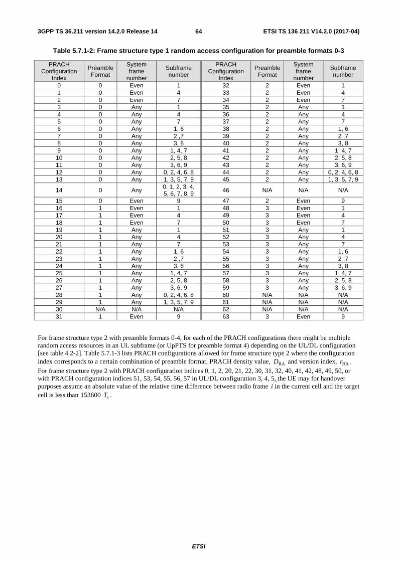
3GPP TS 36.211 version 14.2.0 Release 14 ETSI TS 136 211 V14.2.0 (2017-04)
ETSI
64
Table 5.7.1-2: Frame structure type 1 random access configuration for preamble formats 0-3
PRACH Configuration
Index
Preamble Format
System frame
number
Subframe number
PRACH Configuration
Index
Preamble Format
System frame
number
Subframe number
0 0 Even 1 32 2 Even 1 1 0 Even 4 33 2 Even 4 2 0 Even 7 34 2 Even 7 3 0 Any 1 35 2 Any 1 4 0 Any 4 36 2 Any 4 5 0 Any 7 37 2 Any 7 6 0 Any 1, 6 38 2 Any 1, 6 7 0 Any 2 ,7 39 2 Any 2 ,7 8 0 Any 3, 8 40 2 Any 3, 8 9 0 Any 1, 4, 7 41 2 Any 1, 4, 7
10 0 Any 2, 5, 8 42 2 Any 2, 5, 8 11 0 Any 3, 6, 9 43 2 Any 3, 6, 9 12 0 Any 0, 2, 4, 6, 8 44 2 Any 0, 2, 4, 6, 8 13 0 Any 1, 3, 5, 7, 9 45 2 Any 1, 3, 5, 7, 9
14 0 Any 0, 1, 2, 3, 4, 5, 6, 7, 8, 9 46 N/A N/A N/A
15 0 Even 9 47 2 Even 9 16 1 Even 1 48 3 Even 1 17 1 Even 4 49 3 Even 4 18 1 Even 7 50 3 Even 7 19 1 Any 1 51 3 Any 1 20 1 Any 4 52 3 Any 4 21 1 Any 7 53 3 Any 7 22 1 Any 1, 6 54 3 Any 1, 6 23 1 Any 2 ,7 55 3 Any 2 ,7 24 1 Any 3, 8 56 3 Any 3, 8 25 1 Any 1, 4, 7 57 3 Any 1, 4, 7 26 1 Any 2, 5, 8 58 3 Any 2, 5, 8 27 1 Any 3, 6, 9 59 3 Any 3, 6, 9 28 1 Any 0, 2, 4, 6, 8 60 N/A N/A N/A 29 1 Any 1, 3, 5, 7, 9 61 N/A N/A N/A 30 N/A N/A N/A 62 N/A N/A N/A 31 1 Even 9 63 3 Even 9
For frame structure type 2 with preamble formats 0-4, for each of the PRACH configurations there might be multiple random access resources in an UL subframe (or UpPTS for preamble format 4) depending on the UL/DL configuration [see table 4.2-2]. Table 5.7.1-3 lists PRACH configurations allowed for frame structure type 2 where the configuration index corresponds to a certain combination of preamble format, PRACH density value, RAD and version index, RAr .
For frame structure type 2 with PRACH configuration indices 0, 1, 2, 20, 21, 22, 30, 31, 32, 40, 41, 42, 48, 49, 50, or with PRACH configuration indices 51, 53, 54, 55, 56, 57 in UL/DL configuration 3, 4, 5, the UE may for handover purposes assume an absolute value of the relative time difference between radio frame i in the current cell and the target cell is less than s153600 T⋅ .

3GPP TS 36.211 version 14.2.0 Release 14 ETSI TS 136 211 V14.2.0 (2017-04)
ETSI
65
Table 5.7.1-3: Frame structure type 2 random access configurations for preamble formats 0-4
PRACH configuration
Index
Preamble Format
Density Per 10 ms
RAD
Version
RAr
PRACH configuration
Index
Preamble Format
Density Per 10 ms
RAD
Version
RAr
0 0 0.5 0 32 2 0.5 2 1 0 0.5 1 33 2 1 0 2 0 0.5 2 34 2 1 1 3 0 1 0 35 2 2 0 4 0 1 1 36 2 3 0 5 0 1 2 37 2 4 0 6 0 2 0 38 2 5 0 7 0 2 1 39 2 6 0 8 0 2 2 40 3 0.5 0 9 0 3 0 41 3 0.5 1 10 0 3 1 42 3 0.5 2 11 0 3 2 43 3 1 0 12 0 4 0 44 3 1 1 13 0 4 1 45 3 2 0 14 0 4 2 46 3 3 0 15 0 5 0 47 3 4 0 16 0 5 1 48 4 0.5 0 17 0 5 2 49 4 0.5 1 18 0 6 0 50 4 0.5 2 19 0 6 1 51 4 1 0 20 1 0.5 0 52 4 1 1 21 1 0.5 1 53 4 2 0 22 1 0.5 2 54 4 3 0 23 1 1 0 55 4 4 0 24 1 1 1 56 4 5 0 25 1 2 0 57 4 6 0 26 1 3 0 58 N/A N/A N/A 27 1 4 0 59 N/A N/A N/A 28 1 5 0 60 N/A N/A N/A 29 1 6 0 61 N/A N/A N/A 30 2 0.5 0 62 N/A N/A N/A 31 2 0.5 1 63 N/A N/A N/A
Table 5.7.1-4 lists the mapping to physical resources for the different random access opportunities needed for a certain
PRACH density value, RAD . Each quadruple of the format ),,,( )2(RA
)1(RA
)0(RARA tttf indicates the location of a specific
random access resource, where RAf is a frequency resource index within the considered time instance, 2,1,0)0(RA =t
indicates whether the resource is reoccurring in all radio frames, in even radio frames, or in odd radio frames,
respectively, 1,0)1(RA =t indicates whether the random access resource is located in first half frame or in second half
frame, respectively, and where )2(RAt is the uplink subframe number where the preamble starts, counting from 0 at the
first uplink subframe between 2 consecutive downlink-to-uplink switch points, with the exception of preamble format 4
where )2(RAt is denoted as (*). The start of the random access preamble formats 0-3 shall be aligned with the start of the
corresponding uplink subframe at the UE assuming 0TA =N and the random access preamble format 4 shall start
s4832 T⋅ before the end of the UpPTS at the UE, where the UpPTS is referenced to the UE’s uplink frame timing
assuming 0TA =N .
The random access opportunities for each PRACH configuration shall be allocated in time first and then in frequency if and only if time multiplexing is not sufficient to hold all opportunities of a PRACH configuration needed for a certain density value RAD without overlap in time. For preamble format 0-3, the frequency multiplexing shall be done
according to

3GPP TS 36.211 version 14.2.0 Release 14 ETSI TS 136 211 V14.2.0 (2017-04)
ETSI
66
⎪⎪⎩
⎪⎪⎨
⎧
⎥⎦
⎥⎢⎣
⎢−−−
=⎥⎦
⎥⎢⎣
⎢+=
otherwise,2
66
02mod if,2
6
RARAoffset PRB
ULRB
RARARA
offset PRBRAPRB f
nN
ff
nn
where ULRBN is the number of uplink resource blocks, RA
PRBn is the first physical resource block allocated to the PRACH
opportunity considered and where RAoffset PRBn is the first physical resource block available for PRACH.
For preamble format 4, the frequency multiplexing shall be done according to
( )⎪⎩
⎪⎨⎧
+−=+−×=
otherwise),1(6
02mod)2()2mod( if,6
RAULRB
)1(RASPfRARA
PRBfN
tNnfn
where fn is the system frame number and where SPN is the number of DL to UL switch points within the radio frame.
For BL/CE UEs, only a subset of the subframes allowed for preamble transmission are allowed as starting subframes for the PRACH
repN repetitions. The allowed starting subframes for a PRACH configuration are determined as follows:
- Enumerate the subframes that are allowed for preamble transmission for the PRACH configuration as
1,...0 RAsf
RAsf −= Nn where 0RA
sf =n and 1RAsf
RAsf −= Nn correspond to the two subframes allowed for preamble
transmission with the smallest and the largest absolute subframe number abssfn , respectively.
- If a PRACH starting subframe periodicity PRACHstartN is not provided by higher layers, the periodicity of the
allowed starting subframes in terms of subframes allowed for preamble transmission is PRACHrepN . The allowed
starting subframes defined over 1,...0 RAsf
RAsf −= Nn are given by PRACH
repjN where ... 2, 1, 0,=j
- If a PRACH starting subframe periodicity PRACHstartN is provided by higher layers, it indicates the periodicity of
the allowed starting subframes in terms of subframes allowed for preamble transmission. The allowed starting
subframes defined over 1,...0 RAsf
RAsf −= Nn are given by PRACH
repPRACHstart NjN + where ... 2, 1, 0,=j
- No starting subframe defined over 1,...0 RAsf
RAsf −= Nn such that PRACH
repRAsf
RAsf NNn −> is allowed.
- The subframe with ⎡ ⎤1000*)T + T(10240 SEQCPabssf −>n is not allowed for preamble transmission, where
abssfn denotes the absolute subframe number for single preamble transmission configured by
PRACHConfigurationIndex in Table 5.7.1-2 and Table 5.7.1-4.
Each random access preamble occupies a bandwidth corresponding to 6 consecutive resource blocks for both frame structures.

3GPP TS 36.211 version 14.2.0 Release 14 ETSI TS 136 211 V14.2.0 (2017-04)
ETSI
67
Table 5.7.1-4: Frame structure type 2 random access preamble mapping in time and frequency
PRACH configuration Index (See Table 5.7.1-3)
UL/DL configuration (See Table 4.2-2)
0 1 2 3 4 5 6
0 (0,1,0,2) (0,1,0,1) (0,1,0,0) (0,1,0,2) (0,1,0,1) (0,1,0,0) (0,1,0,2) 1 (0,2,0,2) (0,2,0,1) (0,2,0,0) (0,2,0,2) (0,2,0,1) (0,2,0,0) (0,2,0,2) 2 (0,1,1,2) (0,1,1,1) (0,1,1,0) (0,1,0,1) (0,1,0,0) N/A (0,1,1,1) 3 (0,0,0,2) (0,0,0,1) (0,0,0,0) (0,0,0,2) (0,0,0,1) (0,0,0,0) (0,0,0,2) 4 (0,0,1,2) (0,0,1,1) (0,0,1,0) (0,0,0,1) (0,0,0,0) N/A (0,0,1,1) 5 (0,0,0,1) (0,0,0,0) N/A (0,0,0,0) N/A N/A (0,0,0,1)
6 (0,0,0,2) (0,0,1,2)
(0,0,0,1) (0,0,1,1)
(0,0,0,0) (0,0,1,0)
(0,0,0,1) (0,0,0,2)
(0,0,0,0) (0,0,0,1)
(0,0,0,0) (1,0,0,0)
(0,0,0,2) (0,0,1,1)
7 (0,0,0,1) (0,0,1,1)
(0,0,0,0) (0,0,1,0) N/A (0,0,0,0)
(0,0,0,2) N/A N/A (0,0,0,1) (0,0,1,0)
8 (0,0,0,0) (0,0,1,0)
N/A N/A (0,0,0,0) (0,0,0,1)
N/A N/A (0,0,0,0) (0,0,1,1)
9 (0,0,0,1) (0,0,0,2) (0,0,1,2)
(0,0,0,0) (0,0,0,1) (0,0,1,1)
(0,0,0,0) (0,0,1,0) (1,0,0,0)
(0,0,0,0) (0,0,0,1) (0,0,0,2)
(0,0,0,0) (0,0,0,1) (1,0,0,1)
(0,0,0,0) (1,0,0,0) (2,0,0,0)
(0,0,0,1) (0,0,0,2) (0,0,1,1)
10 (0,0,0,0) (0,0,1,0) (0,0,1,1)
(0,0,0,1) (0,0,1,0) (0,0,1,1)
(0,0,0,0) (0,0,1,0) (1,0,1,0)
N/A (0,0,0,0) (0,0,0,1) (1,0,0,0)
N/A (0,0,0,0) (0,0,0,2) (0,0,1,0)
11 N/A (0,0,0,0) (0,0,0,1) (0,0,1,0)
N/A N/A N/A N/A (0,0,0,1) (0,0,1,0) (0,0,1,1)
12
(0,0,0,1) (0,0,0,2) (0,0,1,1) (0,0,1,2)
(0,0,0,0) (0,0,0,1) (0,0,1,0) (0,0,1,1)
(0,0,0,0) (0,0,1,0) (1,0,0,0) (1,0,1,0)
(0,0,0,0) (0,0,0,1) (0,0,0,2) (1,0,0,2)
(0,0,0,0) (0,0,0,1) (1,0,0,0) (1,0,0,1)
(0,0,0,0) (1,0,0,0) (2,0,0,0) (3,0,0,0)
(0,0,0,1) (0,0,0,2) (0,0,1,0) (0,0,1,1)
13
(0,0,0,0) (0,0,0,2) (0,0,1,0) (0,0,1,2)
N/A N/A
(0,0,0,0) (0,0,0,1) (0,0,0,2) (1,0,0,1)
N/A N/A
(0,0,0,0) (0,0,0,1) (0,0,0,2) (0,0,1,1)
14
(0,0,0,0) (0,0,0,1) (0,0,1,0) (0,0,1,1)
N/A N/A
(0,0,0,0) (0,0,0,1) (0,0,0,2) (1,0,0,0)
N/A N/A
(0,0,0,0) (0,0,0,2) (0,0,1,0) (0,0,1,1)
15
(0,0,0,0) (0,0,0,1) (0,0,0,2) (0,0,1,1) (0,0,1,2)
(0,0,0,0) (0,0,0,1) (0,0,1,0) (0,0,1,1) (1,0,0,1)
(0,0,0,0) (0,0,1,0) (1,0,0,0) (1,0,1,0) (2,0,0,0)
(0,0,0,0) (0,0,0,1) (0,0,0,2) (1,0,0,1) (1,0,0,2)
(0,0,0,0) (0,0,0,1) (1,0,0,0) (1,0,0,1) (2,0,0,1)
(0,0,0,0) (1,0,0,0) (2,0,0,0) (3,0,0,0) (4,0,0,0)
(0,0,0,0) (0,0,0,1) (0,0,0,2) (0,0,1,0) (0,0,1,1)
16
(0,0,0,1) (0,0,0,2) (0,0,1,0) (0,0,1,1) (0,0,1,2)
(0,0,0,0) (0,0,0,1) (0,0,1,0) (0,0,1,1) (1,0,1,1)
(0,0,0,0) (0,0,1,0) (1,0,0,0) (1,0,1,0) (2,0,1,0)
(0,0,0,0) (0,0,0,1) (0,0,0,2) (1,0,0,0) (1,0,0,2)
(0,0,0,0) (0,0,0,1) (1,0,0,0) (1,0,0,1) (2,0,0,0)
N/A N/A
17
(0,0,0,0) (0,0,0,1) (0,0,0,2) (0,0,1,0) (0,0,1,2)
(0,0,0,0) (0,0,0,1) (0,0,1,0) (0,0,1,1) (1,0,0,0)
N/A
(0,0,0,0) (0,0,0,1) (0,0,0,2) (1,0,0,0) (1,0,0,1)
N/A N/A N/A
18
(0,0,0,0) (0,0,0,1) (0,0,0,2) (0,0,1,0) (0,0,1,1) (0,0,1,2)
(0,0,0,0) (0,0,0,1) (0,0,1,0) (0,0,1,1) (1,0,0,1) (1,0,1,1)
(0,0,0,0) (0,0,1,0) (1,0,0,0) (1,0,1,0) (2,0,0,0) (2,0,1,0)
(0,0,0,0) (0,0,0,1) (0,0,0,2) (1,0,0,0) (1,0,0,1) (1,0,0,2)
(0,0,0,0) (0,0,0,1) (1,0,0,0) (1,0,0,1) (2,0,0,0) (2,0,0,1)
(0,0,0,0) (1,0,0,0) (2,0,0,0) (3,0,0,0) (4,0,0,0) (5,0,0,0)
(0,0,0,0) (0,0,0,1) (0,0,0,2) (0,0,1,0) (0,0,1,1) (1,0,0,2)
19 N/A
(0,0,0,0) (0,0,0,1) (0,0,1,0) (0,0,1,1) (1,0,0,0) (1,0,1,0)
N/A N/A N/A N/A
(0,0,0,0) (0,0,0,1) (0,0,0,2) (0,0,1,0) (0,0,1,1) (1,0,1,1)
20 / 30 (0,1,0,1) (0,1,0,0) N/A (0,1,0,1) (0,1,0,0) N/A (0,1,0,1) 21 / 31 (0,2,0,1) (0,2,0,0) N/A (0,2,0,1) (0,2,0,0) N/A (0,2,0,1) 22 / 32 (0,1,1,1) (0,1,1,0) N/A N/A N/A N/A (0,1,1,0) 23 / 33 (0,0,0,1) (0,0,0,0) N/A (0,0,0,1) (0,0,0,0) N/A (0,0,0,1) 24 / 34 (0,0,1,1) (0,0,1,0) N/A N/A N/A N/A (0,0,1,0)
25 / 35 (0,0,0,1) (0,0,1,1)
(0,0,0,0) (0,0,1,0) N/A
(0,0,0,1) (1,0,0,1)
(0,0,0,0) (1,0,0,0) N/A
(0,0,0,1) (0,0,1,0)
26 / 36 (0,0,0,1) (0,0,1,1) (1,0,0,1)
(0,0,0,0) (0,0,1,0) (1,0,0,0)
N/A
(0,0,0,1) (1,0,0,1) (2,0,0,1)
(0,0,0,0) (1,0,0,0) (2,0,0,0)
N/A
(0,0,0,1) (0,0,1,0) (1,0,0,1)

3GPP TS 36.211 version 14.2.0 Release 14 ETSI TS 136 211 V14.2.0 (2017-04)
ETSI
68
27 / 37
(0,0,0,1) (0,0,1,1) (1,0,0,1) (1,0,1,1)
(0,0,0,0) (0,0,1,0) (1,0,0,0) (1,0,1,0)
N/A
(0,0,0,1) (1,0,0,1) (2,0,0,1) (3,0,0,1)
(0,0,0,0) (1,0,0,0) (2,0,0,0) (3,0,0,0)
N/A
(0,0,0,1) (0,0,1,0) (1,0,0,1) (1,0,1,0)
28 / 38
(0,0,0,1) (0,0,1,1) (1,0,0,1) (1,0,1,1) (2,0,0,1)
(0,0,0,0) (0,0,1,0) (1,0,0,0) (1,0,1,0) (2,0,0,0)
N/A
(0,0,0,1) (1,0,0,1) (2,0,0,1) (3,0,0,1) (4,0,0,1)
(0,0,0,0) (1,0,0,0) (2,0,0,0) (3,0,0,0) (4,0,0,0)
N/A
(0,0,0,1) (0,0,1,0) (1,0,0,1) (1,0,1,0) (2,0,0,1)
29 /39
(0,0,0,1) (0,0,1,1) (1,0,0,1) (1,0,1,1) (2,0,0,1) (2,0,1,1)
(0,0,0,0) (0,0,1,0) (1,0,0,0) (1,0,1,0) (2,0,0,0) (2,0,1,0)
N/A
(0,0,0,1) (1,0,0,1) (2,0,0,1) (3,0,0,1) (4,0,0,1) (5,0,0,1)
(0,0,0,0) (1,0,0,0) (2,0,0,0) (3,0,0,0) (4,0,0,0) (5,0,0,0)
N/A
(0,0,0,1) (0,0,1,0) (1,0,0,1) (1,0,1,0) (2,0,0,1) (2,0,1,0)
40 (0,1,0,0) N/A N/A (0,1,0,0) N/A N/A (0,1,0,0) 41 (0,2,0,0) N/A N/A (0,2,0,0) N/A N/A (0,2,0,0) 42 (0,1,1,0) N/A N/A N/A N/A N/A N/A 43 (0,0,0,0) N/A N/A (0,0,0,0) N/A N/A (0,0,0,0) 44 (0,0,1,0) N/A N/A N/A N/A N/A N/A
45 (0,0,0,0) (0,0,1,0) N/A N/A (0,0,0,0)
(1,0,0,0) N/A N/A (0,0,0,0) (1,0,0,0)
46 (0,0,0,0) (0,0,1,0) (1,0,0,0)
N/A
N/A
(0,0,0,0) (1,0,0,0) (2,0,0,0)
N/A
N/A
(0,0,0,0) (1,0,0,0) (2,0,0,0)
47
(0,0,0,0) (0,0,1,0) (1,0,0,0) (1,0,1,0)
N/A
N/A
(0,0,0,0) (1,0,0,0) (2,0,0,0) (3,0,0,0)
N/A
N/A
(0,0,0,0) (1,0,0,0) (2,0,0,0) (3,0,0,0)
48 (0,1,0,*) (0,1,0,*) (0,1,0,*) (0,1,0,*) (0,1,0,*) (0,1,0,*) (0,1,0,*) 49 (0,2,0,*) (0,2,0,*) (0,2,0,*) (0,2,0,*) (0,2,0,*) (0,2,0,*) (0,2,0,*) 50 (0,1,1,*) (0,1,1,*) (0,1,1,*) N/A N/A N/A (0,1,1,*) 51 (0,0,0,*) (0,0,0,*) (0,0,0,*) (0,0,0,*) (0,0,0,*) (0,0,0,*) (0,0,0,*) 52 (0,0,1,*) (0,0,1,*) (0,0,1,*) N/A N/A N/A (0,0,1,*)
53 (0,0,0,*) (0,0,1,*)
(0,0,0,*) (0,0,1,*)
(0,0,0,*) (0,0,1,*)
(0,0,0,*) (1,0,0,*)
(0,0,0,*) (1,0,0,*)
(0,0,0,*) (1,0,0,*)
(0,0,0,*) (0,0,1,*)
54 (0,0,0,*) (0,0,1,*) (1,0,0,*)
(0,0,0,*) (0,0,1,*) (1,0,0,*)
(0,0,0,*) (0,0,1,*) (1,0,0,*)
(0,0,0,*) (1,0,0,*) (2,0,0,*)
(0,0,0,*) (1,0,0,*) (2,0,0,*)
(0,0,0,*) (1,0,0,*) (2,0,0,*)
(0,0,0,*) (0,0,1,*) (1,0,0,*)
55
(0,0,0,*) (0,0,1,*) (1,0,0,*) (1,0,1,*)
(0,0,0,*) (0,0,1,*) (1,0,0,*) (1,0,1,*)
(0,0,0,*) (0,0,1,*) (1,0,0,*) (1,0,1,*)
(0,0,0,*) (1,0,0,*) (2,0,0,*) (3,0,0,*)
(0,0,0,*) (1,0,0,*) (2,0,0,*) (3,0,0,*)
(0,0,0,*) (1,0,0,*) (2,0,0,*) (3,0,0,*)
(0,0,0,*) (0,0,1,*) (1,0,0,*) (1,0,1,*)
56
(0,0,0,*) (0,0,1,*) (1,0,0,*) (1,0,1,*) (2,0,0,*)
(0,0,0,*) (0,0,1,*) (1,0,0,*) (1,0,1,*) (2,0,0,*)
(0,0,0,*) (0,0,1,*) (1,0,0,*) (1,0,1,*) (2,0,0,*)
(0,0,0,*) (1,0,0,*) (2,0,0,*) (3,0,0,*) (4,0,0,*)
(0,0,0,*) (1,0,0,*) (2,0,0,*) (3,0,0,*) (4,0,0,*)
(0,0,0,*) (1,0,0,*) (2,0,0,*) (3,0,0,*) (4,0,0,*)
(0,0,0,*) (0,0,1,*) (1,0,0,*) (1,0,1,*) (2,0,0,*)
57
(0,0,0,*) (0,0,1,*) (1,0,0,*) (1,0,1,*) (2,0,0,*) (2,0,1,*)
(0,0,0,*) (0,0,1,*) (1,0,0,*) (1,0,1,*) (2,0,0,*) (2,0,1,*)
(0,0,0,*) (0,0,1,*) (1,0,0,*) (1,0,1,*) (2,0,0,*) (2,0,1,*)
(0,0,0,*) (1,0,0,*) (2,0,0,*) (3,0,0,*) (4,0,0,*) (5,0,0,*)
(0,0,0,*) (1,0,0,*) (2,0,0,*) (3,0,0,*) (4,0,0,*) (5,0,0,*)
(0,0,0,*) (1,0,0,*) (2,0,0,*) (3,0,0,*) (4,0,0,*) (5,0,0,*)
(0,0,0,*) (0,0,1,*) (1,0,0,*) (1,0,1,*) (2,0,0,*) (2,0,1,*)
58 N/A N/A N/A N/A N/A N/A N/A 59 N/A N/A N/A N/A N/A N/A N/A 60 N/A N/A N/A N/A N/A N/A N/A 61 N/A N/A N/A N/A N/A N/A N/A 62 N/A N/A N/A N/A N/A N/A N/A 63 N/A N/A N/A N/A N/A N/A N/A
NOTE: * UpPTS

3GPP TS 36.211 version 14.2.0 Release 14 ETSI TS 136 211 V14.2.0 (2017-04)
ETSI
69
5.7.2 Preamble sequence generation
The random access preambles are generated from Zadoff-Chu sequences with zero correlation zone, generated from one or several root Zadoff-Chu sequences. The network configures the set of preamble sequences the UE is allowed to use.
There are up to two sets of 64 preambles available in a cell where Set 1 corresponds to higher layer PRACH configuration using prach-ConfigurationIndex and prach-FrequencyOffset and Set 2, if configured, corresponds to higher layer PRACH configuration using prach-ConfigurationIndexHighSpeed and prach-FrequencyOffsetHighSpeed. The set of 64 preamble sequences in a cell is found by including first, in the order of increasing cyclic shift, all the available cyclic shifts of a root Zadoff-Chu sequence with the logical index rootSequenceIndexHighSpeed (for Set 2, if configured) or with the logical index RACH_ROOT_SEQUENCE (for Set 1), where both rootSequenceIndexHighSpeed (if configured) and RACH_ROOT_SEQUENCE are broadcasted as part of the System Information. Additional preamble sequences, in case 64 preambles cannot be generated from a single root Zadoff-Chu sequence, are obtained from the root sequences with the consecutive logical indexes until all the 64 sequences are found. The logical root sequence order is cyclic: the logical index 0 is consecutive to 837. The relation between a logical root sequence index and physical root sequence index u is given by Tables 5.7.2-4 and 5.7.2-5 for preamble formats 0 – 3 and 4, respectively.
The thu root Zadoff-Chu sequence is defined by
( ) 10, ZC
)1(
ZC −≤≤=+−
Nnenx N
nunj
u
π
where the length ZCN of the Zadoff-Chu sequence is given by Table 5.7.2-1. From the thu root Zadoff-Chu sequence,
random access preambles with zero correlation zones of length 1CS −N are defined by cyclic shifts according to
)mod)(()( ZC, NCnxnx vuvu +=
where the cyclic shift is given by
⎣ ⎦
⎣ ⎦ ( )( )( )
RAshift
RAgroup
RAshift
RAshift
RAshift
RAshiftCS
RAshiftstart
RAshiftCSstart
CSRAshift
RAshiftstart
CS
CSCSZCCS
B typesets restrictedfor 1,...,
B typesets restrictedfor 1,...,
B andA typesets restrictedfor 1,...,1,0mod
sets edunrestrictfor 00
sets edunrestrictfor 0,1N0,1,...,v
nnnw
nnwnwvNnwvd
nwwvNwvd
wvNnvnvd
N
NNvN
C v
+=
⎪⎪⎪
⎩
⎪⎪⎪
⎨
⎧
−+++=−−+−+=−+
−=+=
≠−=
=
and CSN is given by Tables 5.7.2-2 and 5.7.2-3 for preamble formats 0-3 and 4, respectively, where the higher-layer
parameters zeroCorrelationZoneConfig and zeroCorrelationZoneConfigHighSpeed shall be used for PRACH preamble Set 1 and Set 2 (if configured), respectively. Restricted set type B shall be used for PRACH preamble Set 2 (if configured), and the parameter High-speed-flag provided by higher layers determines if unrestricted set or restricted set type A shall be used for PRACH preamble Set 1.
The variable ud is the cyclic shift corresponding to a Doppler shift of magnitude SEQ1 T and is given by
⎩⎨⎧
−<≤
=otherwise
20
ZC
ZC
pN
Nppdu
where p is the smallest non-negative integer that fulfils ( ) 1mod ZC =Npu . The parameters for restricted sets of cyclic
shifts depend on ud .
For restricted set type A and 3ZCCS NdN u <≤ , the parameters are given by
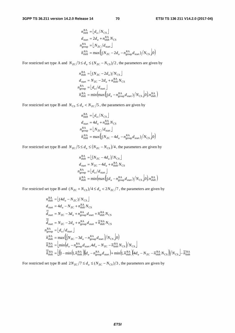
3GPP TS 36.211 version 14.2.0 Release 14 ETSI TS 136 211 V14.2.0 (2017-04)
ETSI
70
⎣ ⎦
⎣ ⎦
⎣ ⎦( )0,)2(max
2
CSstartRAgroupZC
RAshift
startZCRAgroup
CSRAshiftstart
CSRAshift
NdndNn
dNn
Nndd
Ndn
u
u
u
−−=
=
+=
=
For restricted set type A and 2)(3 CSZCZC NNdN u −≤≤ , the parameters are given by
⎣ ⎦
⎣ ⎦
⎣ ⎦( )( )RAshiftCSstart
RAgroup
RAshift
startRAgroup
CSRAshiftZCstart
CSZCRAshift
,0,)(maxmin
2
)2(
nNdndn
ddn
NndNd
NdNn
u
u
u
u
−=
=
+−=
−=
For restricted set type B and 5ZCCS NdN u <≤ , the parameters are given by
⎣ ⎦
⎣ ⎦
⎣ ⎦( )0,)4(max
4
CSstartRAgroupZC
RAshift
startZCRAgroup
CSRAshiftstart
CSRAshift
NdndNn
dNn
Nndd
Ndn
u
u
u
−−=
=
+=
=
For restricted set type B and ( ) 45 CSZCZC NNdN u −≤≤ , the parameters are given by
( )⎣ ⎦
⎣ ⎦
⎣ ⎦( )( )RAshiftCSstart
RAgroup
RAshift
startRAgroup
CSRAshiftZCstart
CSZCRAshift
,0,)(maxmin
4
4
nNdndn
ddn
NndNd
NdNn
u
u
u
u
−=
=
+−=
−=
For restricted set type B and 724)( ZCCSZC NdNN u <≤+ , the parameters are given by
⎣ ⎦
⎣ ⎦
( )⎣ ⎦( )( )⎣ ⎦
( )( )( ) ( )( )( )⎣ ⎦ RAshiftCSCS
RAshiftZC
RAshiftstart
RAgroup
RAshift
RAshift
CSCSRAshiftZCstart
RAgroup
RAshift
CSstartRAgroupZC
RAshift
startRAgroup
CSRA
shiftstartRAgroupZCstart
CSRAshiftstart
RAgroupZCstart
CSRAshiftZCstart
CSZCRAshift
4,1min,1min1
4,min
0,3max
2
3
4
)4(
nNNnNdndndnn
NNnNddndn
NdndNn
ddn
NndndNd
NndndNd
NnNdd
NNdn
uu
uu
u
u
u
u
u
u
−−−+−−=
−−−=
−−=
=
++−=
++−=
+−=
−=
For restricted set type B and 3)(72 CSZCZC NNdN u −≤≤ , the parameters are given by
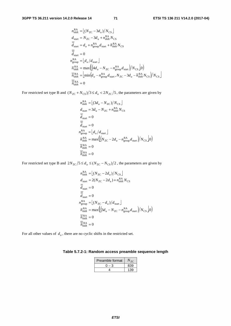
3GPP TS 36.211 version 14.2.0 Release 14 ETSI TS 136 211 V14.2.0 (2017-04)
ETSI
71
⎣ ⎦
⎣ ⎦
( )⎣ ⎦( )( )⎣ ⎦
0
3,min
0,4max
0
3
)3(
RAshift
CSCSRAshiftZCstart
RAgroup
RAshift
CSstartRAgroupZC
RAshift
startRAgroup
start
CSRAshiftstart
RAgroupstart
CSRAshiftZCstart
CSZCRAshift
=
−−−=
−−=
=
=
++=
+−=
−=
n
NNndNdndn
NdnNdn
ddn
d
Nndndd
NndNd
NdNn
uu
u
u
u
u
u
For restricted set type B and 523)( ZCCSZC NdNN u <≤+ , the parameters are given by
⎣ ⎦
⎣ ⎦
( )⎣ ⎦( )
0
0
0,2max
0
0
3
)3(
RAshift
RAshift
CSstartRAgroupZC
RAshift
startRAgroup
start
start
CSRAshiftZCstart
CSZCRAshift
=
=
−−=
=
=
=
+−=
−=
n
n
NdndNn
ddn
d
d
NnNdd
NNdn
u
u
u
u
For restricted set type B and 2)(52 CSZCZC NNdN u −≤≤ , the parameters are given by
⎣ ⎦
⎣ ⎦
( )⎣ ⎦( )
0
0
0,3max
)(
0
0
)2(2
)2(
RAshift
RAshift
CSstartRAgroupZC
RAshift
startZCRAgroup
start
start
CSRAshiftZCstart
CSZCRAshift
=
=
−−=
−=
=
=
+−=
−=
n
n
NdnNdn
ddNn
d
d
NndNd
NdNn
u
u
u
u
For all other values of ud , there are no cyclic shifts in the restricted set.
Table 5.7.2-1: Random access preamble sequence length
Preamble format ZCN
0 – 3 839 4 139

3GPP TS 36.211 version 14.2.0 Release 14 ETSI TS 136 211 V14.2.0 (2017-04)
ETSI
72
Table 5.7.2-2: CSN for preamble generation (preamble formats 0-3)
zeroCorrelationZoneConfig, zeroCorrelationZoneConfigHighSpeed
CSN value
Unrestricted set Restricted set type A Restricted set type B 0 0 15 15 1 13 18 18 2 15 22 22 3 18 26 26 4 22 32 32 5 26 38 38 6 32 46 46 7 38 55 55 8 46 68 68 9 59 82 82
10 76 100 100 11 93 128 118 12 119 158 137 13 167 202 - 14 279 237 - 15 419 - -
Table 5.7.2-3: CSN for preamble generation (preamble format 4)
zeroCorrelationZoneConfig CSN value
0 2 1 4 2 6 3 8 4 10 5 12 6 15 7 N/A 8 N/A 9 N/A 10 N/A 11 N/A 12 N/A 13 N/A 14 N/A 15 N/A

3GPP TS 36.211 version 14.2.0 Release 14 ETSI TS 136 211 V14.2.0 (2017-04)
ETSI
73
Table 5.7.2-4: Root Zadoff-Chu sequence order for preamble formats 0 – 3
Logical root sequence number
Physical root sequence number u (in increasing order of the corresponding logical sequence number)
0–23 129, 710, 140, 699, 120, 719, 210, 629, 168, 671, 84, 755, 105, 734, 93, 746, 70, 769, 60, 779 2, 837, 1, 838
24–29 56, 783, 112, 727, 148, 691 30–35 80, 759, 42, 797, 40, 799 36–41 35, 804, 73, 766, 146, 693 42–51 31, 808, 28, 811, 30, 809, 27, 812, 29, 810 52–63 24, 815, 48, 791, 68, 771, 74, 765, 178, 661, 136, 703 64–75 86, 753, 78, 761, 43, 796, 39, 800, 20, 819, 21, 818 76–89 95, 744, 202, 637, 190, 649, 181, 658, 137, 702, 125, 714, 151, 688
90–115 217, 622, 128, 711, 142, 697, 122, 717, 203, 636, 118, 721, 110, 729, 89, 750, 103, 736, 61, 778, 55, 784, 15, 824, 14, 825
116–135 12, 827, 23, 816, 34, 805, 37, 802, 46, 793, 207, 632, 179, 660, 145, 694, 130, 709, 223, 616
136–167 228, 611, 227, 612, 132, 707, 133, 706, 143, 696, 135, 704, 161, 678, 201, 638, 173, 666, 106, 733, 83, 756, 91, 748, 66, 773, 53, 786, 10, 829, 9, 830
168–203 7, 832, 8, 831, 16, 823, 47, 792, 64, 775, 57, 782, 104, 735, 101, 738, 108, 731, 208, 631, 184, 655, 197, 642, 191, 648, 121, 718, 141, 698, 149, 690, 216, 623, 218, 621
204–263 152, 687, 144, 695, 134, 705, 138, 701, 199, 640, 162, 677, 176, 663, 119, 720, 158, 681, 164, 675, 174, 665, 171, 668, 170, 669, 87, 752, 169, 670, 88, 751, 107, 732, 81, 758, 82, 757, 100, 739, 98, 741, 71, 768, 59, 780, 65, 774, 50, 789, 49, 790, 26, 813, 17, 822, 13, 826, 6, 833
264–327 5, 834, 33, 806, 51, 788, 75, 764, 99, 740, 96, 743, 97, 742, 166, 673, 172, 667, 175, 664, 187, 652, 163, 676, 185, 654, 200, 639, 114, 725, 189, 650, 115, 724, 194, 645, 195, 644, 192, 647, 182, 657, 157, 682, 156, 683, 211, 628, 154, 685, 123, 716, 139, 700, 212, 627, 153, 686, 213, 626, 215, 624, 150, 689
328–383 225, 614, 224, 615, 221, 618, 220, 619, 127, 712, 147, 692, 124, 715, 193, 646, 205, 634, 206, 633, 116, 723, 160, 679, 186, 653, 167, 672, 79, 760, 85, 754, 77, 762, 92, 747, 58, 781, 62, 777, 69, 770, 54, 785, 36, 803, 32, 807, 25, 814, 18, 821, 11, 828, 4, 835
384–455
3, 836, 19, 820, 22, 817, 41, 798, 38, 801, 44, 795, 52, 787, 45, 794, 63, 776, 67, 772, 72 767, 76, 763, 94, 745, 102, 737, 90, 749, 109, 730, 165, 674, 111, 728, 209, 630, 204, 635, 117, 722, 188, 651, 159, 680, 198, 641, 113, 726, 183, 656, 180, 659, 177, 662, 196, 643, 155, 684, 214, 625, 126, 713, 131, 708, 219, 620, 222, 617, 226, 613
456–513 230, 609, 232, 607, 262, 577, 252, 587, 418, 421, 416, 423, 413, 426, 411, 428, 376, 463, 395, 444, 283, 556, 285, 554, 379, 460, 390, 449, 363, 476, 384, 455, 388, 451, 386, 453, 361, 478, 387, 452, 360, 479, 310, 529, 354, 485, 328, 511, 315, 524, 337, 502, 349, 490, 335, 504, 324, 515
514–561 323, 516, 320, 519, 334, 505, 359, 480, 295, 544, 385, 454, 292, 547, 291, 548, 381, 458, 399, 440, 380, 459, 397, 442, 369, 470, 377, 462, 410, 429, 407, 432, 281, 558, 414, 425, 247, 592, 277, 562, 271, 568, 272, 567, 264, 575, 259, 580
562–629 237, 602, 239, 600, 244, 595, 243, 596, 275, 564, 278, 561, 250, 589, 246, 593, 417, 422, 248, 591, 394, 445, 393, 446, 370, 469, 365, 474, 300, 539, 299, 540, 364, 475, 362, 477, 298, 541, 312, 527, 313, 526, 314, 525, 353, 486, 352, 487, 343, 496, 327, 512, 350, 489, 326, 513, 319, 520, 332, 507, 333, 506, 348, 491, 347, 492, 322, 517
630–659 330, 509, 338, 501, 341, 498, 340, 499, 342, 497, 301, 538, 366, 473, 401, 438, 371, 468, 408, 431, 375, 464, 249, 590, 269, 570, 238, 601, 234, 605
660–707 257, 582, 273, 566, 255, 584, 254, 585, 245, 594, 251, 588, 412, 427, 372, 467, 282, 557, 403, 436, 396, 443, 392, 447, 391, 448, 382, 457, 389, 450, 294, 545, 297, 542, 311, 528, 344, 495, 345, 494, 318, 521, 331, 508, 325, 514, 321, 518
708–729 346, 493, 339, 500, 351, 488, 306, 533, 289, 550, 400, 439, 378, 461, 374, 465, 415, 424, 270, 569, 241, 598 730–751 231, 608, 260, 579, 268, 571, 276, 563, 409, 430, 398, 441, 290, 549, 304, 535, 308, 531, 358, 481, 316, 523 752–765 293, 546, 288, 551, 284, 555, 368, 471, 253, 586, 256, 583, 263, 576 766–777 242, 597, 274, 565, 402, 437, 383, 456, 357, 482, 329, 510 778–789 317, 522, 307, 532, 286, 553, 287, 552, 266, 573, 261, 578 790–795 236, 603, 303, 536, 356, 483 796–803 355, 484, 405, 434, 404, 435, 406, 433 804–809 235, 604, 267, 572, 302, 537 810–815 309, 530, 265, 574, 233, 606 816–819 367, 472, 296, 543 820–837 336, 503, 305, 534, 373, 466, 280, 559, 279, 560, 419, 420, 240, 599, 258, 581, 229, 610
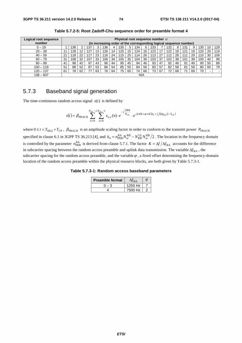
3GPP TS 36.211 version 14.2.0 Release 14 ETSI TS 136 211 V14.2.0 (2017-04)
ETSI
74
Table 5.7.2-5: Root Zadoff-Chu sequence order for preamble format 4
Logical root sequence number
Physical root sequence number u (in increasing order of the corresponding logical sequence number)
0 – 19 1 138 2 137 3 136 4 135 5 134 6 133 7 132 8 131 9 130 10 129 20 – 39 11 128 12 127 13 126 14 125 15 124 16 123 17 122 18 121 19 120 20 119 40 – 59 21 118 22 117 23 116 24 115 25 114 26 113 27 112 28 111 29 110 30 109 60 – 79 31 108 32 107 33 106 34 105 35 104 36 103 37 102 38 101 39 100 40 99 80 – 99 41 98 42 97 43 96 44 95 45 94 46 93 47 92 48 91 49 90 50 89
100 – 119 51 88 52 87 53 86 54 85 55 84 56 83 57 82 58 81 59 80 60 79 120 – 137 61 78 62 77 63 76 64 75 65 74 66 73 67 72 68 71 69 70 - - 138 – 837 N/A
5.7.3 Baseband signal generation
The time-continuous random access signal )(ts is defined by
( ) ( )( ) ( )∑ ∑
−
=
−Δ+++−
=
−⋅⋅=
1
0
21
0
2
,PRACH
ZC
CPRA21
0
ZC
ZC)(N
k
TtfkKkjN
n
N
nkj
vu eenxts ϕππ
β
where CPSEQ0 TTt +<≤ , PRACHβ is an amplitude scaling factor in order to conform to the transmit power PRACHP
specified in clause 6.1 in 3GPP TS 36.213 [4], and 2RBsc
ULRB
RBsc
RAPRB0 NNNnk −= . The location in the frequency domain
is controlled by the parameter RAPRBn is derived from clause 5.7.1. The factor RAffK ΔΔ= accounts for the difference
in subcarrier spacing between the random access preamble and uplink data transmission. The variable RAfΔ , the
subcarrier spacing for the random access preamble, and the variableϕ , a fixed offset determining the frequency-domain
location of the random access preamble within the physical resource blocks, are both given by Table 5.7.3-1.
Table 5.7.3-1: Random access baseband parameters
Preamble format RAfΔ ϕ
0 – 3 1250 Hz 7 4 7500 Hz 2

3GPP TS 36.211 version 14.2.0 Release 14 ETSI TS 136 211 V14.2.0 (2017-04)
ETSI
75
5.8 Modulation and upconversion Modulation and upconversion to the carrier frequency of the complex-valued SC-FDMA baseband signal for each antenna port or the complex-valued PRACH baseband signal is shown in Figure 5.8-1. The filtering required prior to transmission is defined by the requirements in 3GPP TS 36.101 [7].
{ })(Re tsl
{ })(Im tsl
( )tf02cos π
( )tf02sin π−
)(tsl
Figure 5.8-1: Uplink modulation

3GPP TS 36.211 version 14.2.0 Release 14 ETSI TS 136 211 V14.2.0 (2017-04)
ETSI
76
6 Downlink
6.1 Overview The smallest time-frequency unit for downlink transmission is denoted a resource element and is defined in clause 6.2.2.
A subset of the downlink subframes in a radio frame can be configured as MBSFN subframes by higher layers. Each MBSFN subframe is divided into a non-MBSFN region and an MBSFN region.
- For subframes using kHz 15=Δf , the non-MBSFN region spans the first one or two OFDM symbols in an
MBSFN subframe where the length of the non-MBSFN region is given according to Subclause 6.7.
- For subframes using kHz 5.7=Δf or kHz 25.1=Δf , the non-MBSFN region is of zero size.
- The MBSFN region in an MBSFN subframe is defined as the OFDM symbols not used for the non-MBSFN region.
For an MBMS-dedicated cell, subframes where PSS/SSS/PBCH or PDSCH carrying system information are transmitted with kHz 15=Δf are non-MBSFN subframes.
For frame structure type 3, MBSFN configuration shall not be applied to downlink subframes in which at least one OFDM symbol is not occupied or discovery signal is transmitted.
Unless otherwise specified, transmission in each downlink subframe shall use the same cyclic prefix length as used for downlink subframe #0.
6.1.1 Physical channels
A downlink physical channel corresponds to a set of resource elements carrying information originating from higher layers and is the interface defined between 3GPP TS 36.212 [3] and the present document 3GPP TS 36.211. The following downlink physical channels are defined:
- Physical Downlink Shared Channel, PDSCH
- Physical Broadcast Channel, PBCH
- Physical Multicast Channel, PMCH
- Physical Control Format Indicator Channel, PCFICH
- Physical Downlink Control Channel, PDCCH
- Physical Hybrid ARQ Indicator Channel, PHICH
- Enhanced Physical Downlink Control Channel, EPDCCH
- MTC Physical Downlink Control Channel, MPDCCH
6.1.2 Physical signals
A downlink physical signal corresponds to a set of resource elements used by the physical layer but does not carry information originating from higher layers. The following downlink physical signals are defined:
- Reference signal
- Synchronization signal
- Discovery signal

3GPP TS 36.211 version 14.2.0 Release 14 ETSI TS 136 211 V14.2.0 (2017-04)
ETSI
77
6.2 Slot structure and physical resource elements
6.2.1 Resource grid
The transmitted signal in each slot is described by one or several resource grids of RBsc
DLRB NN subcarriers and DL
symbN
OFDM symbols. The resource grid structure is illustrated in Figure 6.2.2-1. The quantity DLRBN depends on the
downlink transmission bandwidth configured in the cell and shall fulfil
DLmax,RB
DLRB
DLmin,RB NNN ≤≤
where 6DLmin,RB =N and 110DLmax,
RB =N are the smallest and largest downlink bandwidths, respectively, supported by
the current version of this specification.
The set of allowed values for DLRBN is given by 3GPP TS 36.104 [6]. The number of OFDM symbols in a slot depends
on the cyclic prefix length and subcarrier spacing configured and is given in Table 6.2.3-1.
An antenna port is defined such that the channel over which a symbol on the antenna port is conveyed can be inferred from the channel over which another symbol on the same antenna port is conveyed. For MBSFN reference signals, positioning reference signals, UE-specific reference signals associated with PDSCH and demodulation reference signals associated with EPDCCH, there are limits given below within which the channel can be inferred from one symbol to another symbol on the same antenna port. There is one resource grid per antenna port. The set of antenna ports supported depends on the reference signal configuration in the cell:
- Cell-specific reference signals support a configuration of one, two, or four antenna ports and are transmitted on antenna ports 0=p , { }1,0∈p , and { }3,2,1,0∈p , respectively.
- MBSFN reference signals are transmitted on antenna port 4=p . The channel over which a symbol on antenna
port 4=p is conveyed can be inferred from the channel over which another symbol on the same antenna port is
conveyed only if the two symbols correspond to subframes of the same MBSFN area.
- UE-specific reference signals associated with PDSCH intended for non-BL/CE UE are transmitted on antenna port(s) 5=p , 7=p , 8=p , or one or several of { }14,13,12,11,10,9,8,7∈p . The channel over which a symbol
on one of these antenna ports is conveyed can be inferred from the channel over which another symbol on the same antenna port is conveyed only if the two symbols are within the same subframe and in the same PRG when PRB bundling is used or in the same PRB pair when PRB bundling is not used.
- - UE-specific reference signals associated with PDSCH intended for BL/CE UE are transmitted on one or several of antenna port(s) { }14,13,12,11,10,9,8,7∈p . The channel over which a symbol on one of these antenna
ports is conveyed can be inferred from the channel over which another symbol on the same antenna port is
conveyed only if the two symbols are in the same set of DLch,NBN consecutive subframes and have the same PRB
index.
- Demodulation reference signals associated with EPDCCH are transmitted on one or several of { }110,109,108,107∈p . The channel over which a symbol on one of these antenna ports is conveyed can be
inferred from the channel over which another symbol on the same antenna port is conveyed only if the two symbols are in the same PRB pair.
- - Demodulation reference signals associated with MPDCCH are transmitted on one or several of { }110,109,108,107∈p . The channel over which a symbol on one of these antenna ports is conveyed can be
inferred from the channel over which another symbol on the same antenna port is conveyed only if the two
symbols are in the same set of DLch,NBN consecutive subframes and have the same PRB index.
- Positioning reference signals are transmitted on antenna port 6=p . The channel over which a symbol on
antenna port 6=p is conveyed can be inferred from the channel over which another symbol on the same
antenna port is conveyed only within one positioning reference signal occasion consisting of PRSN consecutive
downlink subframes, where PRSN is configured by higher layers.

3GPP TS 36.211 version 14.2.0 Release 14 ETSI TS 136 211 V14.2.0 (2017-04)
ETSI
78
- CSI reference signals support a configuration of 1, 2, 4, 8, 12, 16, 20, 24, 28, or 32 antenna ports and are transmitted on antenna ports 15=p , 16,15=p , 18,...,15=p , 22,...,15=p , 26,...,15=p , 30,...,15=p ,
34,...,15=p , 38,...,15=p , 42,...,15=p and 46,...,15=p , respectively.
Two antenna ports are said to be quasi co-located if the large-scale properties of the channel over which a symbol on one antenna port is conveyed can be inferred from the channel over which a symbol on the other antenna port is conveyed. The large-scale properties include one or more of delay spread, Doppler spread, Doppler shift, average gain, and average delay.
6.2.2 Resource elements
Each element in the resource grid for antenna port p is called a resource element and is uniquely identified by the
index pair ( )lk, in a slot where 1,...,0 RBsc
DLRB −= NNk and 1,...,0 DL
symb −= Nl are the indices in the frequency and time
domains, respectively. Resource element ( )lk, on antenna port p corresponds to the complex value )(,plka .
When there is no risk for confusion, or no particular antenna port is specified, the index p may be dropped.
DLsymbN
slotT
0=l 1DLsymb −= Nl
RB
scD
LR
BN
N×
RB
scN
RBsc
DLsymb NN ×
),( lk
0=k
1RBsc
DLRB −= NNk
Figure 6.2.2-1: Downlink resource grid
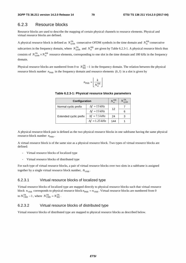
3GPP TS 36.211 version 14.2.0 Release 14 ETSI TS 136 211 V14.2.0 (2017-04)
ETSI
79
6.2.3 Resource blocks
Resource blocks are used to describe the mapping of certain physical channels to resource elements. Physical and virtual resource blocks are defined.
A physical resource block is defined as DLsymbN consecutive OFDM symbols in the time domain and RB
scN consecutive
subcarriers in the frequency domain, where DLsymbN and RB
scN are given by Table 6.2.3-1. A physical resource block thus
consists of RBsc
DLsymb NN × resource elements, corresponding to one slot in the time domain and 180 kHz in the frequency
domain.
Physical resource blocks are numbered from 0 to 1DLRB −N in the frequency domain. The relation between the physical
resource block number PRBn in the frequency domain and resource elements ),( lk in a slot is given by
⎥⎥⎦
⎥
⎢⎢⎣
⎢=
RBsc
PRBN
kn
Table 6.2.3-1: Physical resource blocks parameters
Configuration RBscN
DLsymbN
Normal cyclic prefix kHz 15=Δf
12 7
Extended cyclic prefix
kHz 15=Δf 6
kHz 5.7=Δf 24 3
kHz 25.1=Δf 144 1
A physical resource-block pair is defined as the two physical resource blocks in one subframe having the same physical resource-block number PRBn .
A virtual resource block is of the same size as a physical resource block. Two types of virtual resource blocks are defined:
- Virtual resource blocks of localized type
- Virtual resource blocks of distributed type
For each type of virtual resource blocks, a pair of virtual resource blocks over two slots in a subframe is assigned
together by a single virtual resource block number, VRBn .
6.2.3.1 Virtual resource blocks of localized type
Virtual resource blocks of localized type are mapped directly to physical resource blocks such that virtual resource block VRBn corresponds to physical resource block VRBPRB nn = . Virtual resource blocks are numbered from 0
to 1DLVRB −N , where DL
RBDLVRB NN = .
6.2.3.2 Virtual resource blocks of distributed type
Virtual resource blocks of distributed type are mapped to physical resource blocks as described below.

3GPP TS 36.211 version 14.2.0 Release 14 ETSI TS 136 211 V14.2.0 (2017-04)
ETSI
80
Table 6.2.3.2-1: RB gap values
System BW ( DLRBN )
Gap ( gapN )
1st Gap ( gap,1N ) 2nd Gap ( gap,2N )
6-10 ⎡ ⎤2/DLRBN N/A
11 4 N/A 12-19 8 N/A 20-26 12 N/A 27-44 18 N/A 45-49 27 N/A 50-63 27 9 64-79 32 16
80-110 48 16
The parameter gapN is given by Table 6.2.3.2-1. For 496 DLRB ≤≤ N , only one gap value gap,1N is defined and
gap,1gap NN = . For 11050 DLRB ≤≤ N , two gap values gap,1N and gap,2N are defined. Whether gap,1gap NN = or
gap,2gap NN = is signaled as part of the downlink scheduling assignment as described in 3GPP TS 36.212 [3].
Virtual resource blocks of distributed type are numbered from 0 to 1DLVRB −N , where
),min(2 gapDLRBgap
DLgap1VRB,
DLVRB NNNNN −⋅== for gap,1gap NN = and ⎣ ⎦ gapgap
DLRB
DLgap2VRB,
DLVRB 22/ NNNNN ⋅== for
gap,2gap NN = .
Consecutive DLVRB
~N VRB numbers compose a unit of VRB number interleaving, where DL
VRBDLVRB
~NN = for gap,1gap NN =
and gap
DLVRB 2
~NN = for gap,2gap NN = . Interleaving of VRB numbers of each interleaving unit is performed with 4
columns and rowN rows, where ⎡ ⎤ PPNN ⋅= )4/(~ DL
VRBrow , and P is RBG size as described in 3GPP TS 36.213 [4]. VRB
numbers are written row by row in the rectangular matrix, and read out column by column. nullN nulls are inserted in
the last 2/nullN rows of the 2nd and 4th column, where DLVRBrownull
~4 NNN −= . Nulls are ignored when reading out. The
VRB numbers mapping to PRB numbers including interleaving is derived as follows:
For even slot number sn ;
otherwise ,
24mod~and~~and0,
02mod~and~~and0,
12mod~and~~and0,
~2/~
2/~
~
)(~
VRBnullDLVRBVRBnull
VRBnullDLVRBVRBnull
VRBnullDLVRBVRBnull
PRB
nullPRB
nullrowPRB
rowPRB
sPRB≥−<≠
=−≥≠
=−≥≠
⎪⎪
⎩
⎪⎪
⎨
⎧
′′−′′
+−′−′
=nNNnN
nNNnN
nNNnN
n
Nn
NNn
Nn
nn ,
where ( ) ⎣ ⎦ ⎣ ⎦DLVRBVRB
DLVRBVRBVRBrowPRB
~/
~2/~2mod~2~ NnNnnNn ⋅++⋅=′ ,
and ( ) ⎣ ⎦ ⎣ ⎦DLVRBVRB
DLVRBVRBVRBrowPRB
~/
~4/~4mod~~ NnNnnNn ⋅++⋅=′′ ,
where DLVRBVRBVRB
~mod~ Nnn = and VRBn is obtained from the downlink scheduling assignment as described in
3GPP TS 36.213 [4].
For odd slot number sn ;
( ) ⎣ ⎦DLVRBVRB
DLVRB
DLVRB
DLVRBsPRBsPRB
~/
~~mod2/
~)1(~)(~ NnNNNnnnn ⋅++−=
Then, for all sn ;
⎪⎩
⎪⎨⎧
≥−+<
=2/
~)(~,2/
~)(~
2/~
)(~),(~)( DL
VRBPRBDLVRBgapsPRB
DLVRBPRBsPRB
sPRB NnnNNnn
Nnnnnnn
s
s .
Virtual resource blocks of distributed type are not applicable to BL/CE UEs.

3GPP TS 36.211 version 14.2.0 Release 14 ETSI TS 136 211 V14.2.0 (2017-04)
ETSI
81
6.2.4 Resource-element groups
Resource-element groups are used for defining the mapping of control channels to resource elements.
A resource-element group is represented by the index pair ),( lk ′′ of the resource element with the lowest index k in
the group with all resource elements in the group having the same value of l . The set of resource elements ),( lk in a
resource-element group depends on the number of cell-specific reference signals configured as described below with RBscPRB0 Nnk ⋅= , DL
RBPRB0 Nn <≤ .
- In the first OFDM symbol of the first slot in a subframe the two resource-element groups in physical resource block PRBn consist of resource elements )0,( =lk with 5 ,...,1 ,0 000 +++= kkkk and
11 ,...,7 ,6 000 +++= kkkk , respectively.
- In the second OFDM symbol of the first slot in a subframe in case of one or two cell-specific reference signals configured, the three resource-element groups in physical resource block PRBn consist of resource elements
)1,( =lk with 3 ,...,1 ,0 000 +++= kkkk , 7 ,...,5 ,4 000 +++= kkkk and 11 ,...,9 ,8 000 +++= kkkk ,
respectively.
- In the second OFDM symbol of the first slot in a subframe in case of four cell-specific reference signals configured, the two resource-element groups in physical resource block PRBn consist of resource elements
)1,( =lk with 5 ,...,1 ,0 000 +++= kkkk and 11 ,...,7 ,6 000 +++= kkkk , respectively.
- In the third OFDM symbol of the first slot in a subframe, the three resource-element groups in physical resource block PRBn consist of resource elements )2,( =lk with 3 ,...,1 ,0 000 +++= kkkk , 7 ,...,5 ,4 000 +++= kkkk
and 11 ,...,9 ,8 000 +++= kkkk , respectively.
- In the fourth OFDM symbol of the first slot in a subframe in case of normal cyclic prefix, the three resource-element groups in physical resource block PRBn consist of resource elements )3,( =lk with
3 ,...,1 ,0 000 +++= kkkk , 7 ,...,5 ,4 000 +++= kkkk and 11 ,...,9 ,8 000 +++= kkkk , respectively.
- In the fourth OFDM symbol of the first slot in a subframe in case of extended cyclic prefix, the two resource-element groups in physical resource block PRBn consist of resource elements )3,( =lk with
5 ,...,1 ,0 000 +++= kkkk and 11 ,...,7 ,6 000 +++= kkkk , respectively.
Mapping of a symbol-quadruplet )3(),2(),1(),( +++ iziziziz onto a resource-element group represented by resource-
element ),( lk ′′ is defined such that elements )(iz are mapped to resource elements ),( lk of the resource-element
group not used for cell-specific reference signals in increasing order of i and k . In case a single cell-specific reference signal is configured, cell-specific reference signals shall be assumed to be present on antenna ports 0 and 1 for the purpose of mapping a symbol-quadruplet to a resource-element group, otherwise the number of cell-specific reference signals shall be assumed equal to the actual number of antenna ports used for cell-specific reference signals. The UE shall not make any assumptions about resource elements assumed to be reserved for reference signals but not used for transmission of a reference signal.
For frame structure type 3, if the higher layer parameter subframeStartPosition indicates ‘s07’ and the downlink transmission starts in the second slot of a subframe, the above definition applies to the second slot of that subframe instead of the first slot.
6.2.4A Enhanced Resource-Element Groups (EREGs)
EREGs are used for defining the mapping of enhanced control channels to resource elements.
There are 16 EREGs, numbered from 0 to 15, per physical resource block pair. Number all resource elements, except resource elements carrying DM-RS for antenna ports { }110,109,108,107=p for normal cyclic prefix or { }108,107=p
for extended cyclic prefix, in a physical resource-block pair cyclically from 0 to 15 in an increasing order of first frequency, then time. All resource elements with number i in that physical resource-block pair constitutes EREG number i .
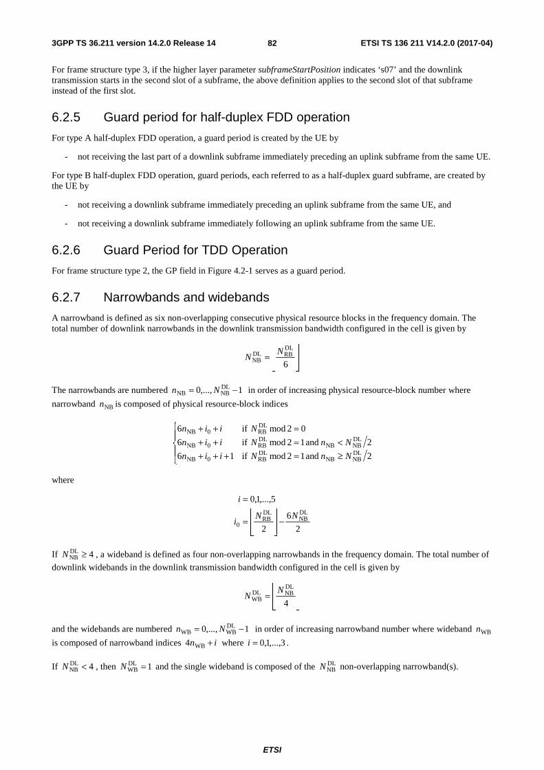
3GPP TS 36.211 version 14.2.0 Release 14 ETSI TS 136 211 V14.2.0 (2017-04)
ETSI
82
For frame structure type 3, if the higher layer parameter subframeStartPosition indicates ‘s07’ and the downlink transmission starts in the second slot of a subframe, the above definition applies to the second slot of that subframe instead of the first slot.
6.2.5 Guard period for half-duplex FDD operation
For type A half-duplex FDD operation, a guard period is created by the UE by
- not receiving the last part of a downlink subframe immediately preceding an uplink subframe from the same UE.
For type B half-duplex FDD operation, guard periods, each referred to as a half-duplex guard subframe, are created by the UE by
- not receiving a downlink subframe immediately preceding an uplink subframe from the same UE, and
- not receiving a downlink subframe immediately following an uplink subframe from the same UE.
6.2.6 Guard Period for TDD Operation
For frame structure type 2, the GP field in Figure 4.2-1 serves as a guard period.
6.2.7 Narrowbands and widebands
A narrowband is defined as six non-overlapping consecutive physical resource blocks in the frequency domain. The total number of downlink narrowbands in the downlink transmission bandwidth configured in the cell is given by
⎥⎥⎦
⎥
⎢⎢⎣
⎢=
6
DLRBDL
NBN
N
The narrowbands are numbered 1,...,0 DLNBNB −= Nn in order of increasing physical resource-block number where
narrowband NBn is composed of physical resource-block indices
⎪⎩
⎪⎨
⎧
≥=+++<=++
=++
2 and 12mod if16
2 and 12mod if6
02mod if6
DLNBNB
DLRB0NB
DLNBNB
DLRB0NB
DLRB0NB
NnNiin
NnNiin
Niin
where
2
6
2
5,...,1,0DLNB
DLRB
0NN
i
i
−⎥⎥⎦
⎥
⎢⎢⎣
⎢=
=
If 4DLNB ≥N , a wideband is defined as four non-overlapping narrowbands in the frequency domain. The total number of
downlink widebands in the downlink transmission bandwidth configured in the cell is given by
⎥⎥⎦
⎥
⎢⎢⎣
⎢=
4
DLNBDL
WBN
N
and the widebands are numbered 1,...,0 DLWBWB −= Nn in order of increasing narrowband number where wideband WBn
is composed of narrowband indices in +WB4 where 3,...,1,0=i .
If 4DLNB <N , then 1DL
WB =N and the single wideband is composed of the DLNBN non-overlapping narrowband(s).

3GPP TS 36.211 version 14.2.0 Release 14 ETSI TS 136 211 V14.2.0 (2017-04)
ETSI
83
6.2.8 Guard period for narrowband and wideband retuning
For BL/CE UEs, a guard period of at most retunesymbN OFDM symbols is created for Rx-to-Rx and Tx-to-Rx frequency
retuning between two consecutive subframes. If the higher layer parameter ce-RetuningSymbols is set, then retunesymbN
equals ce-RetuningSymbols, otherwise 2retunesymb =N . If the higher layer parameter ce-pdsch-maxBandwidth-config is set
to 5 MHz, then the rules for guard period creation defined in the remainder of this clause apply not for retuning between narrowbands but for retuning between widebands and for transmissions involving multiple widebands.
- If the UE retunes from a first downlink narrowband to a second downlink narrowband with a different center
frequency, a guard period is created by the UE not receiving at most retunesymbN OFDM symbols in the second
narrowband.
- If the UE retunes from a first uplink narrowband to a second downlink narrowband with a different center
frequency for frame structure type 2, a guard period is created by the UE not receiving at most retunesymbN OFDM
symbols in the second narrowband.
Furthermore, for BL/CE UEs configured with the higher layer parameter srs-UpPtsAdd, a guard period of at most retunesymbN OFDM or SC-FDMA symbols is created for Rx-to-Tx frequency retuning within a special subframe for frame
structure type 2. Primarily, the TDD guard period (GP) specified in clause 4.2 serves as the guard period for narrowband retuning, and if GP is not sufficient then additional guard period is created by the UE according to:
- If SRS is configured to be transmitted in the first UpPTS symbol, the additional guard period is created by the
UE not receiving at most retunesymbN DwPTS symbols in the first narrowband.
- If SRS is configured to be transmitted in the second UpPTS symbol but not in the first UpPTS symbol, the additional guard period is created by the UE primarily by not transmitting the first UpPTS symbol and (if
2retunesymb =N ) secondarily by not receiving the last DwPTS symbol.
6.3 General structure for downlink physical channels This clause describes a general structure, applicable to more than one physical channel.
The baseband signal representing a downlink physical channel is defined in terms of the following steps:
- scrambling of coded bits in each of the codewords to be transmitted on a physical channel
- modulation of scrambled bits to generate complex-valued modulation symbols
- mapping of the complex-valued modulation symbols onto one or several transmission layers
- precoding of the complex-valued modulation symbols on each layer for transmission on the antenna ports
- mapping of complex-valued modulation symbols for each antenna port to resource elements
- generation of complex-valued time-domain OFDM signal for each antenna port
Figure 6.3-1: Overview of physical channel processing
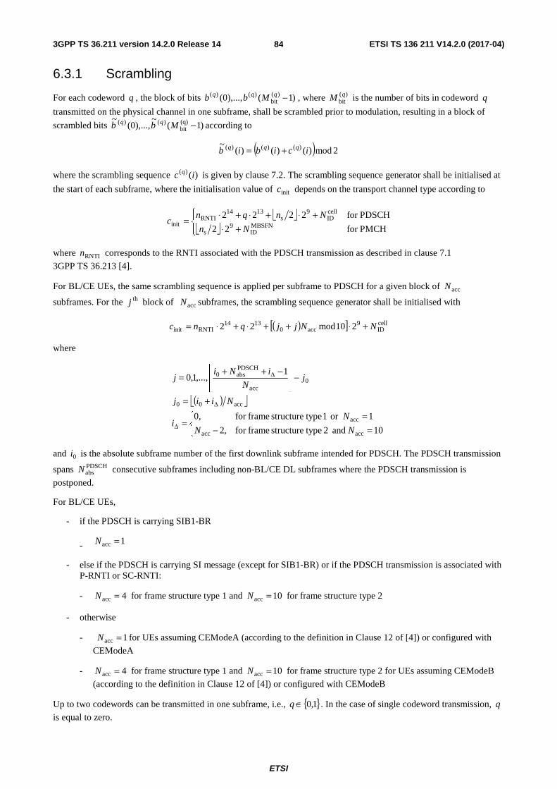
3GPP TS 36.211 version 14.2.0 Release 14 ETSI TS 136 211 V14.2.0 (2017-04)
ETSI
84
6.3.1 Scrambling
For each codeword q , the block of bits )1(),...,0( )(bit
)()( −qqq Mbb , where )(bitqM is the number of bits in codeword q
transmitted on the physical channel in one subframe, shall be scrambled prior to modulation, resulting in a block of
scrambled bits )1(~
),...,0(~ (q)
bit)()( −Mbb qq according to
( ) 2mod)()()(~ )()()( icibib qqq +=
where the scrambling sequence )()( ic q is given by clause 7.2. The scrambling sequence generator shall be initialised at
the start of each subframe, where the initialisation value of initc depends on the transport channel type according to
⎣ ⎦⎣ ⎦⎪⎩
⎪⎨⎧
+⋅+⋅+⋅+⋅=
PMCHfor 22
PDSCHfor 2222MBSFNID
9s
cellID
9s
1314RNTI
initNn
Nnqnc
where RNTIn corresponds to the RNTI associated with the PDSCH transmission as described in clause 7.1
3GPP TS 36.213 [4].
For BL/CE UEs, the same scrambling sequence is applied per subframe to PDSCH for a given block of accN
subframes. For the thj block of accN subframes, the scrambling sequence generator shall be initialised with
( )[ ] cellID
9acc0
1314RNTIinit 210mod22 NNjjqnc +⋅++⋅+⋅=
where
( )⎣ ⎦
⎩⎨⎧
=−=
=
+=
−⎥⎥⎦
⎥
⎢⎢⎣
⎢ −++=
Δ
Δ
Δ
10 and 2 typestructure framefor ,2
1or 1 typestructure framefor 0,
1,...,1,0
accacc
acc
acc00
0acc
PDSCHabs0
NN
Ni
Niij
jN
iNij
and 0i is the absolute subframe number of the first downlink subframe intended for PDSCH. The PDSCH transmission
spans PDSCHabsN consecutive subframes including non-BL/CE DL subframes where the PDSCH transmission is
postponed.
For BL/CE UEs,
- if the PDSCH is carrying SIB1-BR
- 1acc =N
- else if the PDSCH is carrying SI message (except for SIB1-BR) or if the PDSCH transmission is associated with P-RNTI or SC-RNTI:
- 4acc =N for frame structure type 1 and 10acc =N for frame structure type 2
- otherwise
- 1acc =N for UEs assuming CEModeA (according to the definition in Clause 12 of [4]) or configured with
CEModeA
- 4acc =N for frame structure type 1 and 10acc =N for frame structure type 2 for UEs assuming CEModeB
(according to the definition in Clause 12 of [4]) or configured with CEModeB
Up to two codewords can be transmitted in one subframe, i.e., { }1,0∈q . In the case of single codeword transmission, q
is equal to zero.

3GPP TS 36.211 version 14.2.0 Release 14 ETSI TS 136 211 V14.2.0 (2017-04)
ETSI
85
6.3.2 Modulation
For each codeword q , the block of scrambled bits )1(~
),...,0(~ (q)
bit)()( −Mbb qq shall be modulated as described in
clause 7.1 using one of the modulation schemes in Table 6.3.2-1, resulting in a block of complex-valued modulation
symbols )1(),...,0( (q)symb
)()( −Mdd qq .
Table 6.3.2-1: Modulation schemes
Physical channel Modulation schemes PDSCH QPSK, 16QAM, 64QAM, 256QAM PMCH QPSK, 16QAM, 64QAM, 256QAM
6.3.3 Layer mapping
The complex-valued modulation symbols for each of the codewords to be transmitted are mapped onto one or several
layers. Complex-valued modulation symbols )1(),...,0( (q)symb
)()( −Mdd qq for codeword q shall be mapped onto the
layers [ ]Tixixix )(...)()( )1()0( −= υ , 1,...,1,0 layersymb −= Mi where υ is the number of layers and layer
symbM is the number of
modulation symbols per layer, unless 2=υ and “MUST interference presence and power ratio (MUSTIdx)” signalled
in the associated DCI is ‘00’ for only one codeword in which case [ ]Tixixix )()()( )1()1()0()0( αα= , where
( )ββα
−−=
2
12)( j for the layer j for which MUSTIdx is ‘00’, and β
α−
=2
2)( j for the layer j for which MUSTIdx
is not '00’. The value of β is determined from Table 6.3.3-1 using MUSTIdx and the modulation order of the codeword
for which MUSTIdx is not ‘00’.
Table 6.3.3-1: Values for β
MUSTIdx Modulation order QPSK 16QAM 64QAM
01 8/10 32/42 128/170 10 50/58 144.5/167 40.5/51 11 264.5/289 128/138 288/330
6.3.3.1 Layer mapping for transmission on a single antenna port
For transmission on a single antenna port, a single layer is used, 1=υ , and the mapping is defined by
)()( )0()0( idix =
with (0)symb
layersymb MM = .

3GPP TS 36.211 version 14.2.0 Release 14 ETSI TS 136 211 V14.2.0 (2017-04)
ETSI
86
6.3.3.2 Layer mapping for spatial multiplexing
For spatial multiplexing, the layer mapping shall be done according to Table 6.3.3.2-1. The number of layers υ is less than or equal to the number of antenna ports P used for transmission of the physical channel. The case of a single codeword mapped to multiple layers is only applicable when the number of cell-specific reference signals is four or when the number of UE-specific reference signals is two or larger.
Table 6.3.3.2-1: Codeword-to-layer mapping for spatial multiplexing
Number of layers Number of codewords Codeword-to-layer mapping
1,...,1,0 layersymb −= Mi
1 1 )()( )0()0( idix = )0(
symblayersymb MM =
2 1 )12()(
)2()()0()1(
)0()0(
+==
idix
idix 2)0(
symblayersymb MM =
2 2 )()( )0()0( idix = )1(
symb)0(
symblayersymb MMM ==
)()( )1()1( idix =
3 1
)23()(
)13()(
)3()(
)0()2(
)0()1(
)0()0(
+=+=
=
idix
idix
idix 3)0(
symblayersymb MM =
3 2
)()( )0()0( idix =
2)1(symb
)0(symb
layersymb MMM ==
)12()(
)2()()1()2(
)1()1(
+==
idix
idix
4 1
)34()(
)24()(
)14()(
)4()(
)0()3(
)0()2(
)0()1(
)0()0(
+=+=+=
=
idix
idix
idix
idix
4)0(symb
layersymb MM =
4 2 )12()(
)2()()0()1(
)0()0(
+==
idix
idix
22 )1(symb
)0(symb
layersymb MMM ==
)12()(
)2()()1()3(
)1()2(
+==
idix
idix
5 2
)12()(
)2()()0()1(
)0()0(
+==
idix
idix
32 )1(symb
)0(symb
layersymb MMM ==
)23()(
)13()(
)3()(
)1()4(
)1()3(
)1()2(
+=+=
=
idix
idix
idix
6 2 )23()(
)13()(
)3()(
)0()2(
)0()1(
)0()0(
+=+=
=
idix
idix
idix
33 )1(symb
)0(symb
layersymb MMM ==
)23()(
)13()(
)3()(
)1()5(
)1()4(
)1()3(
+=+=
=
idix
idix
idix
7 2
)23()(
)13()(
)3()(
)0()2(
)0()1(
)0()0(
+=+=
=
idix
idix
idix
43 )1(symb
)0(symb
layersymb MMM ==
)34()(
)24()(
)14()(
)4()(
)1()6(
)1()5(
)1()4(
)1()3(
+=+=+=
=
idix
idix
idix
idix
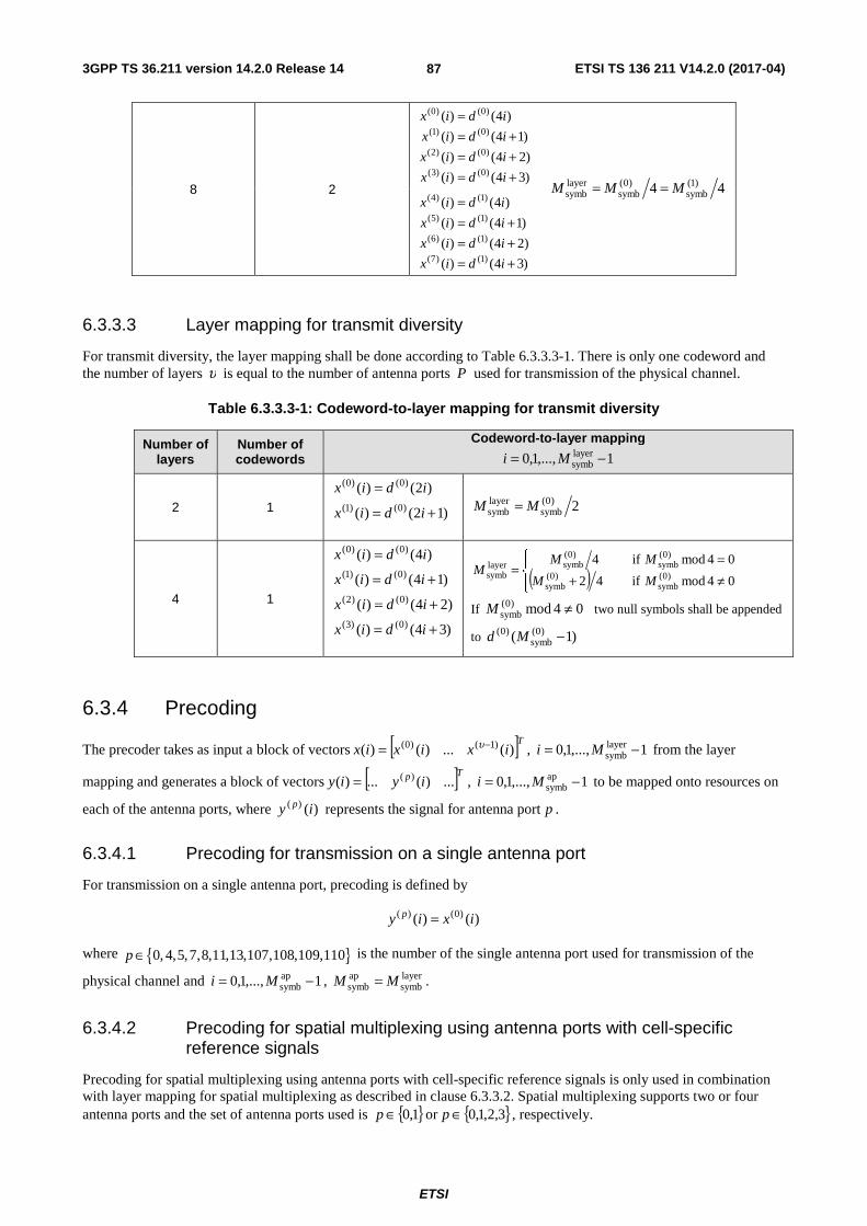
3GPP TS 36.211 version 14.2.0 Release 14 ETSI TS 136 211 V14.2.0 (2017-04)
ETSI
87
8 2 )34()(
)24()(
)14()(
)4()(
)0()3(
)0()2(
)0()1(
)0()0(
+=+=+=
=
idix
idix
idix
idix
44 )1(symb
)0(symb
layersymb MMM ==
)34()(
)24()(
)14()(
)4()(
)1()7(
)1()6(
)1()5(
)1()4(
+=+=+=
=
idix
idix
idix
idix
6.3.3.3 Layer mapping for transmit diversity
For transmit diversity, the layer mapping shall be done according to Table 6.3.3.3-1. There is only one codeword and the number of layers υ is equal to the number of antenna ports P used for transmission of the physical channel.
Table 6.3.3.3-1: Codeword-to-layer mapping for transmit diversity
Number of layers
Number of codewords
Codeword-to-layer mapping
1,...,1,0 layersymb −= Mi
2 1 )12()(
)2()()0()1(
)0()0(
+=
=
idix
idix
2)0(symb
layersymb MM =
4 1
)34()(
)24()(
)14()(
)4()(
)0()3(
)0()2(
)0()1(
)0()0(
+=
+=
+=
=
idix
idix
idix
idix
( )⎪⎩
⎪⎨⎧
≠+=
=04mod if 42
04mod if4)0(
symb)0(
symb
)0(symb
)0(symblayer
symb MM
MMM
If 04mod)0(symb ≠M two null symbols shall be appended
to )1( )0(symb
)0( −Md
6.3.4 Precoding
The precoder takes as input a block of vectors [ ]Tixixix )(...)()( )1()0( −= υ , 1,...,1,0 layersymb −= Mi from the layer
mapping and generates a block of vectors [ ]Tp iyiy ...)(...)( )(= , 1,...,1,0 apsymb −= Mi to be mapped onto resources on
each of the antenna ports, where )()( iy p represents the signal for antenna port p .
6.3.4.1 Precoding for transmission on a single antenna port
For transmission on a single antenna port, precoding is defined by
)()( )0()( ixiy p =
where { }0, 4,5,7,8,11,13,107,108,109,110p ∈ is the number of the single antenna port used for transmission of the
physical channel and 1,...,1,0 apsymb −= Mi , layer
symbapsymb MM = .
6.3.4.2 Precoding for spatial multiplexing using antenna ports with cell-specific reference signals
Precoding for spatial multiplexing using antenna ports with cell-specific reference signals is only used in combination with layer mapping for spatial multiplexing as described in clause 6.3.3.2. Spatial multiplexing supports two or four antenna ports and the set of antenna ports used is { }1,0∈p or { }3,2,1,0∈p , respectively.

3GPP TS 36.211 version 14.2.0 Release 14 ETSI TS 136 211 V14.2.0 (2017-04)
ETSI
88
6.3.4.2.1 Precoding without CDD
Without Cyclic Delay Diversity (CDD), precoding for spatial multiplexing is defined by
⎥⎥⎥
⎦
⎤
⎢⎢⎢
⎣
⎡
=⎥⎥⎥
⎦
⎤
⎢⎢⎢
⎣
⎡
−− )(
)(
)(
)(
)(
)1(
)0(
)1(
)0(
ix
ix
iW
iy
iy
P υMM
where the precoding matrix )(iW is of size υ×P and 1,...,1,0 apsymb −= Mi , layer
symbapsymb MM = .
For spatial multiplexing, the values of )(iW shall be selected among the precoder elements in the codebook configured
in the eNodeB and the UE. The eNodeB can further confine the precoder selection in the UE to a subset of the elements in the codebook using codebook subset restrictions. The configured codebook shall be selected from Table 6.3.4.2.3-1 or 6.3.4.2.3-2.
6.3.4.2.2 Precoding for large delay CDD
For large-delay CDD, precoding for spatial multiplexing is defined by
⎥⎥⎥
⎦
⎤
⎢⎢⎢
⎣
⎡
=⎥⎥⎥
⎦
⎤
⎢⎢⎢
⎣
⎡
−− )(
)(
)()(
)(
)(
)1(
)0(
)1(
)0(
ix
ix
UiDiW
iy
iy
P υMM
where the precoding matrix )(iW is of size υ×P and 1,...,1,0 apsymb −= Mi , layer
symbapsymb MM = . The diagonal size-
υυ × matrix )(iD supporting cyclic delay diversity and the size- υυ × matrix U are both given by Table 6.3.4.2.2-1
for different numbers of layers υ .
The values of the precoding matrix )(iW shall be selected among the precoder elements in the codebook configured in
the eNodeB and the UE. The eNodeB can further confine the precoder selection in the UE to a subset of the elements in the codebook using codebook subset restriction. The configured codebook shall be selected from Table 6.3.4.2.3-1 or 6.3.4.2.3-2.
For 2 antenna ports, the precoder is selected according to 1)( CiW = where 1C denotes the precoding matrix
corresponding to precoder index 0 in Table 6.3.4.2.3-1.
For 4 antenna ports, the UE may assume that the eNodeB cyclically assigns different precoders to different vectors
[ ]Tixix )(...)( )1()0( −υ on the physical downlink shared channel as follows. A different precoder is used every
υ vectors, where υ denotes the number of transmission layers in the case of spatial multiplexing. In particular, the precoder is selected according to kCiW =)( , where k is the precoder index given by
{ }4,3,2,114mod ∈+⎟⎟⎠
⎞⎜⎜⎝
⎛⎥⎦
⎥⎢⎣
⎢=υi
k and 4321 ,,, CCCC denote precoder matrices corresponding to precoder indices
12,13,14 and 15, respectively, in Table 6.3.4.2.3-2.

3GPP TS 36.211 version 14.2.0 Release 14 ETSI TS 136 211 V14.2.0 (2017-04)
ETSI
89
Table 6.3.4.2.2-1: Large-delay cyclic delay diversity
Number of layers υ U )(iD
2 ⎥⎦
⎤⎢⎣
⎡− 221
11
2
1πje
⎥⎦
⎤⎢⎣
⎡− 220
01ije π
3
⎥⎥⎥
⎦
⎤
⎢⎢⎢
⎣
⎡
−−
−−
3834
3432
1
1
111
3
1
ππ
ππ
jj
jj
ee
ee
⎥⎥⎥
⎦
⎤
⎢⎢⎢
⎣
⎡
−
−
34
32
00
00
001
ij
ij
e
eπ
π
4
⎥⎥⎥⎥
⎦
⎤
⎢⎢⎢⎢
⎣
⎡
−−−
−−−
−−−
41841246
4124844
464442
1
1
1
1111
2
1
πππ
πππ
πππ
jjj
jjj
jjj
eee
eee
eee
⎥⎥⎥⎥
⎦
⎤
⎢⎢⎢⎢
⎣
⎡
−
−
−
46
44
42
000
000
000
0001
ij
ij
ij
e
e
e
π
π
π
6.3.4.2.3 Codebook for precoding and CSI reporting
For transmission on two antenna ports, { }1,0∈p , and for the purpose of CSI reporting based on two antenna ports
{ }1,0∈p or { }16,15∈p , the precoding matrix )(iW shall be selected from Table 6.3.4.2.3-1 or a subset thereof. For the
closed-loop spatial multiplexing transmission mode defined in 3GPP TS 36.213 [4], the codebook index 0 is not used when the number of layers is 2=υ .
Table 6.3.4.2.3-1: Codebook for transmission on antenna ports { }1,0 and for CSI reporting based on
antenna ports { }1,0 or { }16,15
Codebook index
Number of layers υ 1 2
0 ⎥⎦
⎤⎢⎣
⎡
1
1
2
1 ⎥
⎦
⎤⎢⎣
⎡
10
01
2
1
1 ⎥⎦
⎤⎢⎣
⎡
−1
1
2
1 ⎥
⎦
⎤⎢⎣
⎡
−11
11
2
1
2 ⎥⎦
⎤⎢⎣
⎡
j
1
2
1 ⎥
⎦
⎤⎢⎣
⎡
− jj
11
2
1
3 ⎥⎦
⎤⎢⎣
⎡
− j
1
2
1 -
For transmission on four antenna ports, { }3,2,1,0∈p , the precoding matrix W shall be selected from Table 6.3.4.2.3-2
or a subset thereof. For the purpose of CSI reporting based on four antenna ports { }3,2,1,0∈p or { }18,17,16,15∈p , the
precoding matrix W shall be selected from Table 6.3.4.2.3-2 or a subset thereof except for alternativeCodeBookEnabledFor4TX -r12 =TRUE in which case the precoding matrix W shall be selected from Tables 7.2.4-0A, 7.2.4-0B, 7.2.4-0C, 7.2.4-0D in [4] or a subset thereof, and except for advancedCodebookEnabled = TRUE in which case the precoding matrix W shall be selected from Table XX in [4] or a subset thereof. The quantity
}{snW denotes the matrix defined by the columns given by the set }{s from the expression n
Hn
Hnnn uuuuIW 2−=
where I is the 44× identity matrix and the vector nu is given by Table 6.3.4.2.3-2.

3GPP TS 36.211 version 14.2.0 Release 14 ETSI TS 136 211 V14.2.0 (2017-04)
ETSI
90
Table 6.3.4.2.3-2: Codebook for transmission on antenna ports { }3,2,1,0 and for CSI reporting based on
antenna ports { }3,2,1,0 or { }18,17,16,15
Codebook index nu Number of layers υ 1 2 3 4
0 [ ]Tu 11110 −−−= }1{0W 2}14{
0W 3}124{0W 2}1234{
0W
1 [ ]Tjju 111 −= }1{1W 2}12{
1W 3}123{1W 2}1234{
1W
2 [ ]Tu 11112 −= }1{2W 2}12{
2W 3}123{2W 2}3214{
2W
3 [ ]Tjju −= 113 }1{3W 2}12{
3W 3}123{3W 2}3214{
3W
4 [ ]Tjjju 2)1(2)1(14 −−−−= }1{
4W 2}14{4W 3}124{
4W 2}1234{4W
5 [ ]Tjjju 2)1(2)1(15 −−−= }1{
5W 2}14{5W 3}124{
5W 2}1234{5W
6 [ ]Tjjju 2)1(2)1(16 +−−+= }1{
6W 2}13{6W 3}134{
6W 2}1324{6W
7 [ ]Tjjju 2)1(2)1(17 ++−= }1{
7W 2}13{7W 3}134{
7W 2}1324{7W
8 [ ]Tu 11118 −= }1{8W 2}12{
8W 3}124{8W 2}1234{
8W
9 [ ]Tjju −−−= 119 }1{9W 2}14{
9W 3}134{9W 2}1234{
9W
10 [ ]Tu 111110 −= }1{10W 2}13{
10W 3}123{10W 2}1324{
10W
11 [ ]Tjju 1111 −= }1{11W 2}13{
11W 3}134{11W 2}1324{
11W
12 [ ]Tu 111112 −−= }1{12W 2}12{
12W 3}123{12W 2}1234{
12W
13 [ ]Tu 111113 −−= }1{13W 2}13{
13W 3}123{13W 2}1324{
13W
14 [ ]Tu 111114 −−= }1{14W 2}13{
14W 3}123{14W 2}3214{
14W
15 [ ]Tu 111115 = }1{15W 2}12{
15W 3}123{15W 2}1234{
15W
For the purpose of CSI reporting for 8, 12, 16, 20, 24, 28, and 32 CSI reference signals the codebooks are given in clause 7.2.4 of 3GPP TS 36.213 [4].
6.3.4.3 Precoding for transmit diversity
Precoding for transmit diversity is only used in combination with layer mapping for transmit diversity as described in clause 6.3.3.3. The precoding operation for transmit diversity is defined for two and four antenna ports.
For transmission on two antenna ports, { }1,0∈p , the output [ ]Tiyiyiy )()()( )1()0(= , 1,...,1,0 apsymb −= Mi of the
precoding operation is defined by
( )( )( )( )⎥⎥
⎥⎥⎥
⎦
⎤
⎢⎢⎢⎢⎢
⎣
⎡
⎥⎥⎥⎥
⎦
⎤
⎢⎢⎢⎢
⎣
⎡
−
−=
⎥⎥⎥⎥⎥
⎦
⎤
⎢⎢⎢⎢⎢
⎣
⎡
++
)(Im
)(Im
)(Re
)(Re
001
010
010
001
2
1
)12(
)12(
)2(
)2(
)1(
)0(
)1(
)0(
)1(
)0(
)1(
)0(
ix
ix
ix
ix
j
j
j
j
iy
iy
iy
iy
for 1,...,1,0 layersymb −= Mi with layer
symbapsymb 2MM = .
If the higher-layer parameter semiOpenLoop is set, for rank=1 transmission on two antenna ports, { }8,7∈p , the output
[ ]Tiyiyiy )()()( )8()7(= , 1,...,1,0 apsymb −= Mi of the precoding operation is defined by
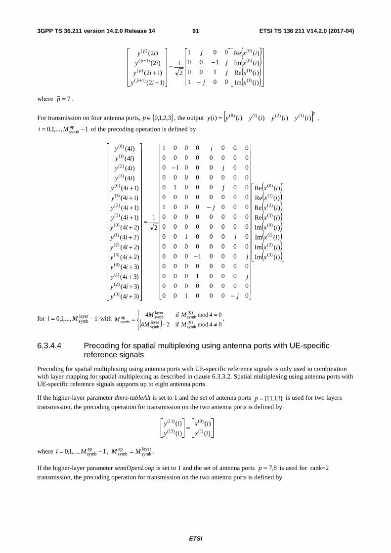
3GPP TS 36.211 version 14.2.0 Release 14 ETSI TS 136 211 V14.2.0 (2017-04)
ETSI
91
( )( )( )( )⎥⎥
⎥⎥⎥
⎦
⎤
⎢⎢⎢⎢⎢
⎣
⎡
⎥⎥⎥⎥
⎦
⎤
⎢⎢⎢⎢
⎣
⎡
−
−=
⎥⎥⎥⎥⎥
⎦
⎤
⎢⎢⎢⎢⎢
⎣
⎡
++
+
+
)(Im
)(Re
)(Im
)(Re
001
100
100
001
2
1
)12(
)12(
)2(
)2(
)1(
)1(
)0(
)0(
)1(
)(
)1(
)(
ix
ix
ix
ix
j
j
j
j
iy
iy
iy
iy
p
p
p
p
where 7=p .
For transmission on four antenna ports, { }3,2,1,0∈p , the output [ ]Tiyiyiyiyiy )()()()()( )3()2()1()0(= ,
1,...,1,0 apsymb −= Mi of the precoding operation is defined by
( )( )( )( )( )( )( )( )⎥⎥
⎥⎥⎥⎥⎥⎥⎥⎥⎥
⎦
⎤
⎢⎢⎢⎢⎢⎢⎢⎢⎢⎢⎢
⎣
⎡
⎥⎥⎥⎥⎥⎥⎥⎥⎥⎥⎥⎥⎥⎥⎥⎥⎥⎥⎥⎥⎥⎥⎥
⎦
⎤
⎢⎢⎢⎢⎢⎢⎢⎢⎢⎢⎢⎢⎢⎢⎢⎢⎢⎢⎢⎢⎢⎢⎢
⎣
⎡
−
−
−
−
=
⎥⎥⎥⎥⎥⎥⎥⎥⎥⎥⎥⎥⎥⎥⎥⎥⎥⎥⎥⎥⎥⎥⎥⎥
⎦
⎤
⎢⎢⎢⎢⎢⎢⎢⎢⎢⎢⎢⎢⎢⎢⎢⎢⎢⎢⎢⎢⎢⎢⎢⎢
⎣
⎡
++++++++++++
)(Im
)(Im
)(Im
)(Im
)(Re
)(Re
)(Re
)(Re
0000100
00000000
0001000
00000000
0001000
00000000
0000100
00000000
00000000
0000001
00000000
0000010
00000000
0000010
00000000
0000001
2
1
)34(
)34(
)34(
)34(
)24(
)24(
)24(
)24(
)14(
)14(
)14(
)14(
)4(
)4(
)4(
)4(
)3(
)2(
)1(
)0(
)3(
)2(
)1(
)0(
)3(
)2(
)1(
)0(
)3(
)2(
)1(
)0(
)3(
)2(
)1(
)0(
)3(
)2(
)1(
)0(
ix
ix
ix
ix
ix
ix
ix
ix
j
j
j
j
j
j
j
j
iy
iy
iy
iy
iy
iy
iy
iy
iy
iy
iy
iy
iy
iy
iy
iy
for 1,...,1,0 layersymb −= Mi with ( )⎪⎩
⎪⎨⎧
≠−=
=04mod if24
04mod if4)0(
symblayersymb
)0(symb
layersymbap
symb MM
MMM .
6.3.4.4 Precoding for spatial multiplexing using antenna ports with UE-specific reference signals
Precoding for spatial multiplexing using antenna ports with UE-specific reference signals is only used in combination with layer mapping for spatial multiplexing as described in clause 6.3.3.2. Spatial multiplexing using antenna ports with UE-specific reference signals supports up to eight antenna ports.
If the higher-layer parameter dmrs-tableAlt is set to 1 and the set of antenna ports {11,13}p = is used for two layers
transmission, the precoding operation for transmission on the two antenna ports is defined by
⎥⎥⎦
⎤
⎢⎢⎣
⎡=
⎥⎥⎦
⎤
⎢⎢⎣
⎡
)(
)(
)(
)()1(
)0(
)13(
)11(
ix
ix
iy
iy
where 1,...,1,0 apsymb −= Mi , layer
symbapsymb MM = .
If the higher-layer parameter semiOpenLoop is set to 1 and the set of antenna ports 8,7=p is used for rank=2
transmission, the precoding operation for transmission on the two antenna ports is defined by
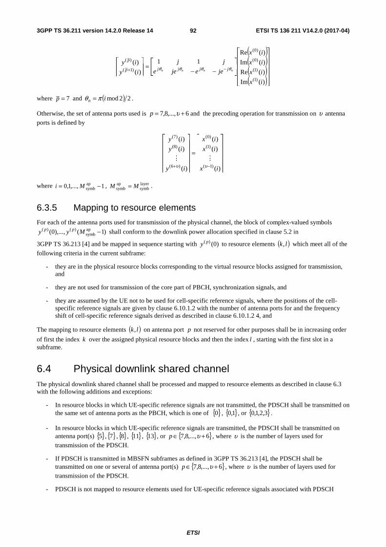
3GPP TS 36.211 version 14.2.0 Release 14 ETSI TS 136 211 V14.2.0 (2017-04)
ETSI
92
( )( )( )( )⎥⎥
⎥⎥⎥
⎦
⎤
⎢⎢⎢⎢⎢
⎣
⎡
⎥⎦
⎤⎢⎣
⎡
−−=
⎥⎥⎦
⎤
⎢⎢⎣
⎡−+
)(Im
)(Re
)(Im
)(Re11
)(
)(
)1(
)1(
)0(
)0(
)1(
)(
ix
ix
ix
ix
jeejee
jj
iy
iynnnn jjjjp
p
θθθθ
where 7=p and ( ) 22modin πθ = .
Otherwise, the set of antenna ports used is 6,...,8,7 += υp and the precoding operation for transmission on υ antenna
ports is defined by
⎥⎥⎥⎥⎥
⎦
⎤
⎢⎢⎢⎢⎢
⎣
⎡
=
⎥⎥⎥⎥⎥
⎦
⎤
⎢⎢⎢⎢⎢
⎣
⎡
−+ )(
)(
)(
)(
)(
)(
)1(
)1(
)0(
)6(
)8(
)7(
ix
ix
ix
iy
iy
iy
υυMM
where 1,...,1,0 apsymb −= Mi , layer
symbapsymb MM = .
6.3.5 Mapping to resource elements
For each of the antenna ports used for transmission of the physical channel, the block of complex-valued symbols
)1(),...,0( apsymb
)()( −Myy pp shall conform to the downlink power allocation specified in clause 5.2 in
3GPP TS 36.213 [4] and be mapped in sequence starting with )0()( py to resource elements ( )lk, which meet all of the
following criteria in the current subframe:
- they are in the physical resource blocks corresponding to the virtual resource blocks assigned for transmission, and
- they are not used for transmission of the core part of PBCH, synchronization signals, and
- they are assumed by the UE not to be used for cell-specific reference signals, where the positions of the cell-specific reference signals are given by clause 6.10.1.2 with the number of antenna ports for and the frequency shift of cell-specific reference signals derived as described in clause 6.10.1.2 4, and
The mapping to resource elements ( )lk, on antenna port p not reserved for other purposes shall be in increasing order
of first the index k over the assigned physical resource blocks and then the index l , starting with the first slot in a subframe.
6.4 Physical downlink shared channel The physical downlink shared channel shall be processed and mapped to resource elements as described in clause 6.3 with the following additions and exceptions:
- In resource blocks in which UE-specific reference signals are not transmitted, the PDSCH shall be transmitted on the same set of antenna ports as the PBCH, which is one of { }0 , { }1,0 , or { }3,2,1,0 .
- In resource blocks in which UE-specific reference signals are transmitted, the PDSCH shall be transmitted on antenna port(s) { }5 , { }7 , { }8 , { }11 , { }13 , or { }6,...,8,7 +∈ υp , where υ is the number of layers used for
transmission of the PDSCH.
- If PDSCH is transmitted in MBSFN subframes as defined in 3GPP TS 36.213 [4], the PDSCH shall be transmitted on one or several of antenna port(s) { }6,...,8,7 +∈ υp , where υ is the number of layers used for
transmission of the PDSCH.
- PDSCH is not mapped to resource elements used for UE-specific reference signals associated with PDSCH

3GPP TS 36.211 version 14.2.0 Release 14 ETSI TS 136 211 V14.2.0 (2017-04)
ETSI
93
- In mapping to resource elements, the positions of the cell-specific reference signals are given by clause 6.10.1.2 with the number of antenna ports and the frequency shift of the cell-specific reference signals derived as described in clause 6.10.1.2, unless other values for these parameters are provided by clause 7.1.9 in 3GPP TS 36.213 [4], in which case these values are used in the resource blocks indicated by the relevant DCI.
- If the DCI associated with the PDSCH uses the C-RNTI or semi-persistent C-RNTI, the PDSCH is not mapped to resource elements assumed by the UE to be used for transmission of:
- zero-power CSI reference signals, where the positions of the CSI reference signals are given by clause 6.10.5.2.The configuration for zero power CSI reference signals is
- obtained as described in clause 6.10.5.2, unless other values for these parameters are provided by clause 7.1.9 in 3GPP TS 36.213 [4], in which case these values are used in the resource blocks indicated by the relevant DCI, and
- obtained by higher-layer configuration of up to five reserved CSI-RS resources as part of the discovery signal configuration following the procedure for zero-power CSI-RS in clause 6.10.5.2.
- non-zero-power CSI reference signals for CSI reporting, where the positions of the non-zero-power CSI reference signals for CSI reporting are given by clause 6.10.5.2. The configuration for non-zero power CSI reference signals is obtained as described in clause 6.10.5.2.
- PDSCH is not mapped to any physical resource-block pair(s) carrying an EPDCCH associated with the PDSCH.
- PDSCH on antenna port 5, 7, 8, 9, 10, 11, 12, 13 or 14 is not mapped to any physical resource-block pair(s) carrying PBCH or synchronization signals.
- For frame structure type 1 and 2, the index l in the first slot in a subframe fulfils DataStartll ≥ where DataStartl is
given by clause 7.1.6.4 of 3GPP TS 36.213 [4].
- For frame structure type 3,
- if the higher layer parameter subframeStartPosition indicates ‘s07’ and the downlink transmission starts in the second slot of a subframe
- the index l in the second slot in a subframe fulfils DataStartll ≥ where DataStartl is given by clause 7.1.6.4
of 3GPP TS 36.213 [4],
- otherwise
- the index l in the first slot in a subframe fulfils DataStartll ≥ where DataStartl is given by clause 7.6.1.4 of
3GPP TS 36.213 [4],
- In mapping to resource elements, if the DCI associated with the PDSCH uses the C-RNTI or semi-persistent C-RNTI, and transmit diversity according to clause 6.3.4.3 is used, and if the higher-layer parameter semiOpenLoop is not set, resource elements in an OFDM symbol assumed by the UE to contain CSI-RS shall be used in the mapping if and only if all of the following criteria are fulfilled:
- there is an even number of resource elements for the OFDM symbol in each resource block assigned for transmission, and
- the complex-valued symbols )()( iy p and )1()( +iy p , where i is an even number, can be mapped to resource
elements ( )lk, and ( )lnk ,+ in the same OFDM symbol with 3<n .
- In mapping to resource elements, if the DCI associated with the PDSCH uses C-RNTI or semi-persistent C-RNTI and if the higher-layer parameter semiOpenLoop is set, a pair of resource elements ( )lk ,' , ( )lnk ,'+ shall
be used in the mapping if and only if
- the complex-valued symbols )()( iy p and )1()( +iy p can be mapped to resource elements ( )lk ,' and ( )lnk ,'+
in the same OFDM symbol and the same PRB with 3<n , where i is an even number and k ′ starts from 0 at the lowest subcarrier of the PRB.

3GPP TS 36.211 version 14.2.0 Release 14 ETSI TS 136 211 V14.2.0 (2017-04)
ETSI
94
6.4.1 Physical downlink shared channel for BL/CE UEs
For BL/CE UEs, the following additions and exceptions hold in addition to those in clause 6.4:
- The maximum number of allocatable PRBs for PDSCH is restricted as follows:
- If the PDSCH is associated with C-RNTI or SPS C-RNTI and the higher layer parameter ce-pdsch-maxBandwidth-config is set,
- if the higher layer parameter ce-pdsch-maxBandwidth-config is set to 20 MHz, the maximum number of allocatable PRBs for PDSCH is 96 PRBs restricted to the narrowbands defined in clause 6.2.7;
- if the higher layer parameter ce-pdsch-maxBandwidth-config is set to 5 MHz, the maximum number of allocatable PRBs for PDSCH is 24 PRBs restricted to no more than four of the narrowbands defined in clause 6.2.7.
- If the PDSCH is associated with G-RNTI and the higher layer parameter pdsch-MaxBandwidth-SC-MTCH is set to 24 PRBs, the maximum number of allocatable PRBs for PDSCH is 24 PRBs restricted to no more than four of the narrowbands defined in clause 6.2.7.
- For all other cases, the maximum number of allocatable PRBs for PDSCH is 6 PRBs restricted to one of the narrowbands defined in clause 6.2.7.
- Resource elements occupied by CSI reference signals shall be counted in the PDSCH mapping but not used for transmission of the PDSCH.
- Resource elements belonging to synchronization signals, the core part of PBCH, PBCH repetitions, or resource elements reserved for reference signals in the mapping operation of PBCH but not used for transmission of reference signals, shall be counted in the PDSCH mapping but not used for transmission of the PDSCH.
- For BL/CE UEs in CEModeB configured in transmission mode 9, in MBSFN subframe(s), resource elements that correspond to the positions of cell-specific reference signals as in subframe #0 shall not be counted in the PDSCH mapping and not used for transmission of the PDSCH.
For BL/CE UEs, if the PDSCH is not carrying SIB1-BR the PRB resources for PDSCH transmission in the first subframe are obtained from the DCI as described in clauses 5.3.3.1.12, 5.3.3.1.13, and 5.5.1.3.14 in [3], or provided by
higher layers. The PDSCH is transmitted with 1PDSCHrep ≥N repetitions, spanning PDSCH
repPDSCHabs NN ≥ consecutive
subframes, including non-BL/CE DL subframes where the the PDSCH transmission is postponed.
- If frequency hopping is not enabled for PDSCH, all PDSCH repetitions are located at the same PRB resources, and
- if frequency hopping is enabled for PDSCH, the PDSCH shall be transmitted in subframe i within the PDSCHabsN
consecutive downlink subframes using the same PRB resources within each narrowband
( ) ( )
( )⎣ ⎦
⎩⎨⎧
−=
−+≤≤
+=
⎟⎟
⎠
⎞
⎜⎜
⎝
⎛⋅
⎟⎟
⎠
⎞
⎜⎜
⎝
⎛
⎥⎥⎦
⎥
⎢⎢⎣
⎢−++=
Δ
Δ
Δ
2 typestructure framefor ,2
1 typestructure framefor 0,
1
modmod
DLch,NB
PDSCHabs00
DLch,NB00
DLNB
DLhopNB,
DLch,hopNB,0DLch,
NBNBNB
0
Ni
Niii
Niij
Nf N jN
iinn ii
where 0i is the absolute subframe number of the first downlink subframe intended for PDSCH and DLch,NBN ,
DLch,hopNB,N and DL
hopNB,f are cell-specific higher-layer parameters. For PDSCH carrying SI other than SIB1-BR and
for PDSCH associated with P-RNTI, if interval-DlHoppingConfigCommonModeB is signalled in SIB1-BR, then
the frequency hopping granularity DLch,NBN is set to interval-DlHoppingConfigCommonModeB; otherwise,
DLch,NBN is set to interval-DlHoppingConfigCommonModeA signalled in SIB1-BR.

3GPP TS 36.211 version 14.2.0 Release 14 ETSI TS 136 211 V14.2.0 (2017-04)
ETSI
95
For BL/CE UE in CEModeA, frequency hopping of PDSCH associated with C-RNTI or SPS C-RNTI is enabled when higher layer parameter mpdcch-pdsch-HoppingConfig is set and the frequency hopping flag in DCI format 6-1A indicates frequency hopping, otherwise, frequency hopping of is not enabled. For BL/CE UE in CEModeB, frequency hopping of PDSCH associated with C-RNTI or SPS-RNTI is enabled when higher layer parameter mpdcch-pdsch-HoppingConfig is set, otherwise, frequency hopping of is not enabled.
The UE shall not expect PDSCH in subframe i if it is not a BL/CE DL subframe.
For BL/CE UEs, if the PDSCH carries SIB1-BR, the PDSCH transmission is repeated periodically in every period of 8 radio frames, where a period starts with a radio frame with 08modf =n where fn is the system frame number. The
PDSCH is transmitted BR-SIB1PDSCHN times in each period of 8 frames, Let { }js be the set of narrowbands, excluding
narrowbands overlapping with the 72 center subcarriers for 15DLRB >N , and ordered in increasing order of narrowband
index. The PDSCH transmission cycles through the set { }is of narrowbands in increasing order of i , starting with 0=i
for the first subframe, according to
⎣ ⎦( )
⎪⎩
⎪⎨
⎧
<≤≤
<=
−=⋅+=
=
DLRB
DLRB
DLRB
SNB
SNB
SNB
cellID
NB
504
50122
121
1,...,1,0
modmod
N
N
N
m
mi
NmNiNNj
sn j
where SNBN is the number of narrowbands in the set { }js .
The set of frames and subframes used for SIB1-BR transmission in each period are given by Tables 6.4.1-1 and 6.4.1-2.
Table 6.4.1-1: The set of frames and subframes for SIB1-BR for 15DLRB ≤N .
BR-SIB1PDSCHN 2modcell
IDN
Frame structure type 1 Frame structure type 2 2modfn sfn 2modfn sfn
4 0 0 4 1 5 1 1 4 1 5
Table 6.4.1-2: The set of frames and subframes for SIB1-BR for 15DLRB >N .
BR-SIB1PDSCHN 2modcell
IDN
Frame structure type 1 Frame structure type 2 2modfn sfn 2modfn sfn
4 0 0 4 1 5 1 1 4 1 0
8 0 0, 1 4 0, 1 5 1 0, 1 9 0, 1 0
16 0 0, 1 4, 9 0, 1 0, 5 1 0, 1 0, 9 0, 1 0, 5
BL/CE UEs may assume the same precoding matrix being used for a PRB across a block of DLch,NBN consecutive
subframes when UE-specific reference signals are transmitted together with the PDSCH.
For PDSCH transmission associated with SI-RNTI or P-RNTI to BL/CE UEs, frequency hopping of the PDSCH is enabled when higher layer parameter si-HoppingConfigCommon is set.
For PDSCH transmission associated with RA-RNTI or temporary C-RNTI to BL/CE UEs, frequency hopping of the PDSCH is enabled when higher layer parameter rar-HoppingConfig is set. Further

3GPP TS 36.211 version 14.2.0 Release 14 ETSI TS 136 211 V14.2.0 (2017-04)
ETSI
96
- if PRACH CE level 0 or 1 is used for the last PRACH attempt, DLch,NBN is set to the higher layer parameter
interval-DlHoppingConfigCommonModeA;
- if PRACH CE level 2 or 3 is used for the last PRACH attempt, DLch,NBN is set to the higher layer parameter
interval-DlHoppingConfigCommonModeB.
For PDSCH transmission associated with SC-RNTI to BL/CE UEs, frequency hopping of the PDSCH is enabled when higher layer parameter mpdcch-pdsch-HoppingConfig-SC-MCCH is set. Further
- if mpdcch-pdsch-HoppingConfig-SC-MCCH is set to CEModeA, DLch,NBN is set to the higher layer parameter
interval-DlHoppingConfigCommonModeA;
- if mpdcch-pdsch-HoppingConfig-SC-MCCH is set to CEModeB, DLch,NBN is set to the higher layer parameter
interval-DlHoppingConfigCommonModeB.
For PDSCH transmission associated with G-RNTI to BL/CE UEs,
- if the higher layer parameter mpdcch-pdsch-CEmodeConfig-SC-MTCH is set to CEModeA,
- if the higher layer parameter mpdcch-pdsch-HoppingConfig-SC-MTCH is set and the frequency hopping flag in DCI format 6-1A indicates frequency hopping, then frequency hopping of the PDSCH is enabled and
DLch,NBN is set to the higher layer parameter interval-DlHoppingConfigCommonModeA, otherwise frequency
hopping is not enabled;
- if the higher layer parameter mpdcch-pdsch-CEmodeConfig-SC-MTCH is set to CEModeB,
- if the higher layer parameter mpdcch-pdsch-HoppingConfig-SC-MTCH is set, then frequency hopping of the
PDSCH is enabled and DLch,NBN is set to the higher layer parameter interval-
DlHoppingConfigCommonModeB, otherwise frequency hopping is not enabled.
6.5 Physical multicast channel The physical multicast channel shall be processed and mapped to resource elements as described in clause 6.3 with the following exceptions:
- No transmit diversity scheme is specified.
- Layer mapping and precoding shall be done assuming a single antenna port and the transmission shall use antenna port 4.
- The PMCH can only be transmitted in the MBSFN region of an MBSFN subframe. The index l in the first slot
in the MBSFN subframe fulfils PMCHStartll ≥ where PMCHStartl is equal to the value given by the higher layer
parameter non-MBSFNregionLength [9].
- The PMCH shall use extended cyclic prefix.
- The PMCH is not mapped to resource elements used for transmission of MBSFN reference signals.
6.6 Physical broadcast channel The PBCH is not transmitted for frame structure type 3.
6.6.1 Scrambling
The block of bits )1(),...,0( bit −Mbb , where bitM , the number of bits transmitted on the physical broadcast channel,
equals 1920 for normal cyclic prefix and 1728 for extended cyclic prefix, shall be scrambled with a cell-specific
sequence prior to modulation, resulting in a block of scrambled bits )1(~
),...,0(~
bit −Mbb according to

3GPP TS 36.211 version 14.2.0 Release 14 ETSI TS 136 211 V14.2.0 (2017-04)
ETSI
97
( ) 2mod)()()(~
icibib +=
where the scrambling sequence )(ic is given by clause 7.2. The scrambling sequence shall be initialised with cellIDinit Nc = in each radio frame fulfilling 04modf =n . For an MBMS-dedicated cell, the scrambling sequence shall be
initialised with cellID
9init 2 Nc += in each radio frame fulfilling 016modf =n .
6.6.2 Modulation
The block of scrambled bits )1(~
),...,0(~
bit −Mbb shall be modulated as described in clause 7.1, resulting in a block of
complex-valued modulation symbols )1(),...,0( symb −Mdd . Table 6.6.2-1 specifies the modulation mappings applicable
for the physical broadcast channel.
Table 6.6.2-1: PBCH modulation schemes.
Physical channel Modulation schemes PBCH QPSK
6.6.3 Layer mapping and precoding
The block of modulation symbols )1(),...,0( symb −Mdd shall be mapped to layers according to one of clauses 6.3.3.1 or
6.3.3.3 with symb)0(
symb MM = and precoded according to one of clauses 6.3.4.1 or 6.3.4.3, resulting in a block of vectors
[ ]TP iyiyiy )(...)()( )1()0( −= , 1,...,0 symb −= Mi , where )()( iy p represents the signal for antenna port p and where
1,...,0 −= Pp and the number of antenna ports for cell-specific reference signals { }4,2,1∈P .
6.6.4 Mapping to resource elements
The block of complex-valued symbols )1(),...,0( symb)()( −Myy pp for each antenna port shall
- for an MBMS-dedicated cell, be transmitted during 4 consecutive radio frames fulfilling 04modf =n , starting
in each radio frame fulfilling 016modf =n , and
- otherwise, be transmitted during 4 consecutive radio frames, starting in each radio frame fulfilling 04modf =n .
The block of complex-valued symbols shall be mapped in sequence starting with )0(y to resource elements ( )lk,
constituting the core set of PBCH resource elements. The mapping to resource elements ( )lk, not reserved for
transmission of reference signals shall be in increasing order of first the index k , then the index l in slot 1 in subframe 0 and finally the radio frame number. The resource-element indices are given by
3,...,1,0
71,...,1,0' ,'362
RBsc
DLRB
=
=+−=
l
kkNN
k
where resource elements reserved for reference signals shall be excluded. The mapping operation shall assume cell-specific reference signals for antenna ports 0-3 being present irrespective of the actual configuration. The UE shall assume that the resource elements assumed to be reserved for reference signals in the mapping operation above but not used for transmission of reference signal are not available for PDSCH or MPDCCH transmission. The UE shall not make any other assumptions about these resource elements.
If a cell is configured with repetition of the physical broadcast channel
- symbols mapped to core resource element ( )lk, in slot 1 in subframe 0 within a radio frame fn according to the
mapping operation above, and

3GPP TS 36.211 version 14.2.0 Release 14 ETSI TS 136 211 V14.2.0 (2017-04)
ETSI
98
- cell-specific reference signals in OFDM symbols l in slot 1 in subframe 0 within a radio frame fn with l
according to the mapping operation above
shall additionally be mapped to resource elements ( )lk ′, in slot number sn′ within radio frame in −f unless resource
element ( )lk ′, is used by CSI reference signals.
For frame structure type 1, l′ , sn′ , and i are given by Table 6.6.4-1.
For frame structure type 2,
- if 15DLRB >N , l′ and sn′ are given by Table 6.6.4-2 and 0=i ;
- if 157 DLRB ≤≤ N , l′ and sn′ are given by Table 6.6.4-2 and 0=i , except that repetitions with 10s =′n and
11s =′n are not applied.
For both frame structure type 1 and frame structure type 2, repetition of the physical broadcast channel is not applicable
if 6DLRB =N .
Resource elements already used for transmission of cell-specific reference signals in absence of repetition shall not be used for additional mapping of cell-specific reference signals.
Table 6.6.4-1: Frame offset, slot and symbol number triplets for repetition of PBCH for frame structure type 1.
l Frame offset, slot and symbol number triplets ( )',, s lni ′
Normal cyclic prefix Extended cyclic prefix 0 (1,18,3), (1,19,0), (1,19,4), (0,0,4) (1,18,3), (1,19,0), (1,19,5) 1 (1,18,4), (1,19,1). (1,19,5), (0,1,4) (1,18,4), (1,19,1). (0,0,3) 2 (1,18,5), (1,19,2), (1,19,6), (0,1,5) (1,18,5), (1,19,2), (0,1,4) 3 (1,18,6), (1,19,3), (0,0,3), (0,1,6) (1,19,3), (1,19,4), (0,1,5)
Table 6.6.4-2: Slot and symbol number pairs for repetition of PBCH for frame structure type 2.
l Slot and symbol number pairs ( )',s ln′
Normal cyclic prefix Extended cyclic prefix 0 (0,3), (1,4), (10,3), (11,0), (11,4) (0,3), (10,3), (11,0) 1 (0,4), (1,5), (10,4), (11,1), (11,5) (0,4), (10,4), (11,1) 2 (0,5), (10,5), (11.2) (0,5), (10,5), (11.2) 3 (0,6), (10,6), (11.3) (1,4), (11,3), (11.4)
6.7 Physical control format indicator channel The physical control format indicator channel carries information about the number of OFDM symbols used for transmission of PDCCHs in a subframe. The set of OFDM symbols possible to use for PDCCH in a subframe is given by Table 6.7-1.

3GPP TS 36.211 version 14.2.0 Release 14 ETSI TS 136 211 V14.2.0 (2017-04)
ETSI
99
Table 6.7-1: Number of OFDM symbols used for PDCCH
Subframe
Number of OFDM symbols for PDCCH
when 10DLRB >N
Number of OFDM symbols for PDCCH
when 10DLRB ≤N
Subframe 1 and 6 for frame structure type 2 or a subframe for frame structure type 3 with the same duration as the DwPTS duration of a special subframe configuration
1, 2 2
MBSFN subframes with kHz 15=Δf and configured with 1 or
2 cell-specific antenna ports 1, 2 2
MBSFN subframes with kHz 15=Δf and configured with 4
cell-specific antenna ports 2 2
MBSFN subframes with kHz 5.7=Δf or kHz 25.1=Δf 0 0
Non-MBSFN subframes (except subframe 6 for frame structure type 2) configured with positioning reference signals 1, 2, 3 2, 3
All other cases 1, 2, 3 2, 3, 4
The UE may assume the PCFICH is transmitted when the number of OFDM symbols for PDCCH is greater than zero unless stated otherwise in [4, clause 12].
6.7.1 Scrambling
The block of bits )31(),...,0( bb transmitted in one subframe shall be scrambled with a cell-specific sequence prior to
modulation, resulting in a block of scrambled bits )31(~
),...,0(~
bb according to
( ) 2mod)()()(~
icibib +=
where the scrambling sequence )(ic is given by clause 7.2. The scrambling sequence generator shall be initialised with
⎣ ⎦( ) ( ) cellID
9cellIDsinit 21212 NNnc +⋅+⋅+= at the start of each subframe.
6.7.2 Modulation
The block of scrambled bits )31(~
),...,0(~
bb shall be modulated as described in clause 7.1, resulting in a block of
complex-valued modulation symbols )15(),...,0( dd . Table 6.7.2-1 specifies the modulation mappings applicable for the
physical control format indicator channel.
Table 6.7.2-1: PCFICH modulation schemes
Physical channel Modulation schemes PCFICH QPSK
6.7.3 Layer mapping and precoding
The block of modulation symbols )15(),...,0( dd shall be mapped to layers according to one of clauses 6.3.3.1 or 6.3.3.3
with 16)0(symb =M and precoded according to one of clauses 6.3.4.1 or 6.3.4.3, resulting in a block of vectors
[ ]TP iyiyiy )(...)()( )1()0( −= , 15,...,0=i , where )()( iy p represents the signal for antenna port p and where
1,...,0 −= Pp and the number of antenna ports for cell-specific reference signals { }4,2,1∈P . The PCFICH shall be
transmitted on the same set of antenna ports as the PBCH.

3GPP TS 36.211 version 14.2.0 Release 14 ETSI TS 136 211 V14.2.0 (2017-04)
ETSI
100
6.7.4 Mapping to resource elements
The mapping to resource elements is defined in terms of quadruplets of complex-valued symbols. Let
)34(),24(),14(),4()( )()()()()( +++= iyiyiyiyiz ppppp denote symbol quadruplet i for antenna port p . For each of
the antenna ports, symbol quadruplets shall be mapped in increasing order of i to the four resource-element groups in the first OFDM symbol in a downlink subframe or DwPTS with the representative resource-element as defined in clause 6.2.4 given by
⎣ ⎦⎣ ⎦⎣ ⎦ 223by drepresente groupelement -resource the tomapped is)3(
222by drepresente groupelement -resource the tomapped is)2(
22by drepresente groupelement -resource the tomapped is)1(
by drepresente groupelement -resource the tomapped is)0(
RBsc
DLRB
)(
RBsc
DLRB
)(
RBsc
DLRB
)(
)(
NNkkz
NNkkz
NNkkz
kkz
p
p
p
p
⋅+=
⋅+=
⋅+==
where the additions are modulo RBsc
DLRB NN ,
( ) ( )DLRB
cellID
RBsc 2mod2 NNNk ⋅=
and cellIDN is the physical-layer cell identity as given by clause 6.11.
6.8 Physical downlink control channel
6.8.1 PDCCH formats
The physical downlink control channel carries scheduling assignments and other control information. A physical control channel is transmitted on an aggregation of one or several consecutive control channel elements (CCEs), where a control channel element corresponds to 9 resource element groups. The number of resource-element groups not assigned to PCFICH or PHICH is REGN . The CCEs available in the system are numbered from 0 to 1CCE −N , where
⎣ ⎦9/REGCCE NN = . The PDCCH supports multiple formats as listed in Table 6.8.1-1. A PDCCH consisting of n
consecutive CCEs may only start on a CCE fulfilling 0mod =ni , where i is the CCE number.
Multiple PDCCHs can be transmitted in a subframe.
Table 6.8.1-1: Supported PDCCH formats
PDCCH format Number of CCEs Number of resource-element groups Number of PDCCH bits 0 1 9 72 1 2 18 144 2 4 36 288 3 8 72 576
6.8.2 PDCCH multiplexing and scrambling
The block of bits )1(),...,0( (i)bit
)()( −Mbb ii on each of the control channels to be transmitted in a subframe, where (i)bitM
is the number of bits in one subframe to be transmitted on physical downlink control channel number i , shall be multiplexed, resulting in a block of bits
)1(),...,0(),...,1(),...,0(),1(),...,0( 1)-(bit
)1()1((1)bit
)1()1((0)bit
)0()0( PDCCHPDCCHPDCCH −−− −− nnn MbbMbbMbb , where PDCCHn is the
number of PDCCHs transmitted in the subframe.
The block of bits )1(),...,0(),...,1(),...,0(),1(),...,0( 1)-(bit
)1()1((1)bit
)1()1((0)bit
)0()0( PDCCHPDCCHPDCCH −−− −− nnn MbbMbbMbb shall be
scrambled with a cell-specific sequence prior to modulation, resulting in a block of scrambled bits
)1(~
),...,0(~
tot −Mbb according to
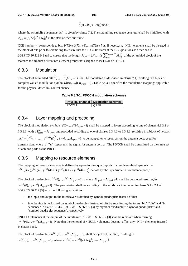
3GPP TS 36.211 version 14.2.0 Release 14 ETSI TS 136 211 V14.2.0 (2017-04)
ETSI
101
( ) 2mod)()()(~
icibib +=
where the scrambling sequence )(ic is given by clause 7.2. The scrambling sequence generator shall be initialised with
⎣ ⎦ cellID
9sinit 22 Nnc += at the start of each subframe.
CCE number n corresponds to bits )7172(),...,172(),72( ++ nbnbnb . If necessary, <NIL> elements shall be inserted in
the block of bits prior to scrambling to ensure that the PDCCHs starts at the CCE positions as described in
3GPP TS 36.213 [4] and to ensure that the length ∑−
=≥=
1
0
)(bitREGtot
PDCCH8n
i
iMNM of the scrambled block of bits
matches the amount of resource-element groups not assigned to PCFICH or PHICH.
6.8.3 Modulation
The block of scrambled bits )1(~
),...,0(~
tot −Mbb shall be modulated as described in clause 7.1, resulting in a block of
complex-valued modulation symbols )1(),...,0( symb −Mdd . Table 6.8.3-1 specifies the modulation mappings applicable
for the physical downlink control channel.
Table 6.8.3-1: PDCCH modulation schemes
Physical channel Modulation schemes PDCCH QPSK
6.8.4 Layer mapping and precoding
The block of modulation symbols )1(),...,0( symb −Mdd shall be mapped to layers according to one of clauses 6.3.3.1 or
6.3.3.3 with symb)0(
symb MM = and precoded according to one of clauses 6.3.4.1 or 6.3.4.3, resulting in a block of vectors
[ ]TP iyiyiy )(...)()( )1()0( −= , 1,...,0 symb −= Mi to be mapped onto resources on the antenna ports used for
transmission, where )()( iy p represents the signal for antenna port p . The PDCCH shall be transmitted on the same set
of antenna ports as the PBCH.
6.8.5 Mapping to resource elements
The mapping to resource elements is defined by operations on quadruplets of complex-valued symbols. Let
)34(),24(),14(),4()( )()()()()( +++= iyiyiyiyiz ppppp denote symbol quadruplet i for antenna port p .
The block of quadruplets )1(),...,0( quad)()( −Mzz pp , where 4symbquad MM = , shall be permuted resulting in
)1(),...,0( quad)()( −Mww pp . The permutation shall be according to the sub-block interleaver in clause 5.1.4.2.1 of
3GPP TS 36.212 [3] with the following exceptions:
- the input and output to the interleaver is defined by symbol quadruplets instead of bits
- interleaving is performed on symbol quadruplets instead of bits by substituting the terms "bit", "bits" and "bit sequence" in clause 5.1.4.2.1 of 3GPP TS 36.212 [3] by "symbol quadruplet", "symbol quadruplets" and "symbol-quadruplet sequence", respectively
<NULL> elements at the output of the interleaver in 3GPP TS 36.212 [3] shall be removed when forming
)1(),...,0( quad)()( −Mww pp . Note that the removal of <NULL> elements does not affect any <NIL> elements inserted
in clause 6.8.2.
The block of quadruplets )1(),...,0( quad)()( −Mww pp shall be cyclically shifted, resulting in
)1(),...,0( quad)()( −Mww pp where ( ) ( )quad
cellID
)()( mod)( MNiwiw pp += .
3GPP TS 36.211 version 14.2.0 Release 14 ETSI TS 136 211 V14.2.0 (2017-04)
ETSI
102
Mapping of the block of quadruplets )1(),...,0( quad)()( −Mww pp is defined in terms of resource-element groups,
specified in clause 6.2.4, according to steps 1–10 below:
1) Initialize 0=′m (resource-element group number)
2) Initialize 0'=k
3) Initialize 0'=l
4) If the resource element ),( lk ′′ represents a resource-element group and the resource-element group is not
assigned to PCFICH or PHICH then perform step 5 and 6, else go to step 7
5) Map symbol-quadruplet )'()( mw p to the resource-element group represented by ),( lk ′′ for each
antenna port p
6) Increase m′ by 1
7) Increase 'l by 1
8) Repeat from step 4 if Ll <' , where L corresponds to the number of OFDM symbols used for PDCCH transmission as indicated by the sequence transmitted on the PCFICH
9) Increase 'k by 1
10) Repeat from step 3 if RBsc
DLRB' NNk ⋅<
PDCCHs shall not be transmitted in MBSFN subframes with zero-size non-MBSFN region.
6.8A Enhanced physical downlink control channel For frame structure type 3, for a subframe with the same duration as the DwPTS duration of a special subframe configuration, the enhanced physical downlink control channel is defined the same as that for the corresponding special subframe configuration.
6.8A.1 EPDCCH formats
The enhanced physical downlink control channel (EPDCCH) carries scheduling assignments. An enhanced physical downlink control channel is transmitted using an aggregation of one or several consecutive enhanced control channel elements (ECCEs) where each ECCE consists of multiple enhanced resource element groups (EREGs), defined in clause 6.2.4A. The number of ECCEs used for one EPDCCH depends on the EPDCCH format as given by Table 6.8A.1-2 and the number of EREGs per ECCE is given by Table 6.8A.1-1.Both localized and distributed transmission is supported.
An EPDCCH can use either localized or distributed transmission, differing in the mapping of ECCEs to EREGs and PRB pairs.
A UE shall monitor multiple EPDCCHs as defined in 3GPP TS 36.213 [4]. One or two sets of physical resource-block pairs which a UE shall monitor for EPDCCH transmissions can be configured. All EPDCCH candidates in EPDCCH
set mX use either only localized or only distributed transmission as configured by higher layers. Within EPDCCH set
mX in subframe i , the ECCEs available for transmission of EPDCCHs are numbered from 0 to 1,,ECCE −imN and
ECCE number n corresponds to
- EREGs numbered ( ) RBECCE
RBECCEmod NjNn + in PRB index ⎣ ⎦RB
ECCE/ Nn for localized mapping, and
- EREGs numbered ⎣ ⎦ RBECCERB jNNn mX + in PRB indices ( )( ) mm XX
NNNjn RBECCEEREGRB mod,1max+ for distributed
mapping,
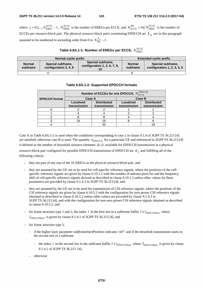
3GPP TS 36.211 version 14.2.0 Release 14 ETSI TS 136 211 V14.2.0 (2017-04)
ETSI
103
where 1,...,1,0 ECCEEREG −= Nj , ECCE
EREGN is the number of EREGs per ECCE, and ECCEEREG
RBECCE 16 NN = is the number of
ECCEs per resource-block pair. The physical resource-block pairs constituting EPDCCH set mX are in this paragraph
assumed to be numbered in ascending order from 0 to 1RB −mXN .
Table 6.8A.1-1: Number of EREGs per ECCE, ECCEEREGN
Normal cyclic prefix Extended cyclic prefix
Normal subframe
Special subframe, configuration 3, 4, 8
Special subframe, configuration 1, 2, 6, 7, 9,
10
Normal subframe
Special subframe, configuration 1, 2, 3, 5, 6
4 8
Table 6.8A.1-2: Supported EPDCCH formats
EPDCCH format
Number of ECCEs for one EPDCCH, EPDCCHECCEN
Case A Case B Localized
transmission Distributed
transmission Localized
transmission Distributed
transmission 0 2 2 1 1 1 4 4 2 2 2 8 8 4 4 3 16 16 8 8 4 - 32 - 16
Case A in Table 6.8A.1-2 is used when the conditions corresponding to case 1 in clause 9.1.4 of 3GPP TS 36.213 [4] are satisfied, otherwise case B is used. The quantity EPDCCHn for a particular UE and referenced in 3GPP TS 36.213 [4]
is defined as the number of downlink resource elements ),( lk available for EPDCCH transmission in a physical
resource-block pair configured for possible EPDCCH transmission of EPDCCH set 0X and fulfilling all of the
following criteria:
- they are part of any one of the 16 EREGs in the physical resource-block pair, and
- they are assumed by the UE not to be used for cell-specific reference signals, where the positions of the cell-specific reference signals are given by clause 6.10.1.2 with the number of antenna ports for and the frequency shift of cell-specific reference signals derived as described in clause 6.10.1.2 unless other values for these parameters are provided by clause 9.1.4.3 in 3GPP TS 36.213 [4], and-
- they are assumed by the UE not to be used for transmission of CSI reference signals, where the positions of the CSI reference signals are given by clause 6.10.5.2 with the configuration for zero power CSI reference signals obtained as described in clause 6.10.5.2 unless other values are provided by clause 9.1.4.3 in 3GPP TS 36.213 [4], and with the configuration for non-zero power CSI reference signals obtained as described in clause 6.10.5.2, and
- for frame structure type 1 and 2, the index l in the first slot in a subframe fulfils tEPDCCHStarll ≥ where
tEPDCCHStarl is given by clause 9.1.4.1 of 3GPP TS 36.213 [4], and
- for frame structure type 3,
- if the higher layer parameter subframeStartPosition indicates ‘s07’ and if the downlink transmission starts in the second slot of a subframe
- the index l in the second slot in the subframe fulfils tEPDCCHStarll ≥ where tEPDCCHStarl is given by clause
9.1.4.1 of 3GPP TS 36.213 [4],
- otherwise

3GPP TS 36.211 version 14.2.0 Release 14 ETSI TS 136 211 V14.2.0 (2017-04)
ETSI
104
- the index l in the first slot in the subframe fulfils tEPDCCHStarll ≥ where tEPDCCHStarl is given by clause
9.1.4.1 of 3GPP TS 36.213 [4].
6.8A.2 Scrambling
The block of bits )1(),...,0( bit −Mbb to be transmitted on an EPDCCH in a subframe shall be scrambled, resulting in a
block of scrambled bits )1(~
),...,0(~
bit −Mbb according to
( ) 2mod)()()(~
icibib +=
where the UE-specific scrambling sequence )(ic is given by clause 7.2. The scrambling sequence generator shall be
initialized with ⎣ ⎦ EPDCCH,ID
9sinit 22 mnnc +⋅= where m is the EPDCCH set number.
6.8A.3 Modulation
The block of scrambled bits )1(~
),...,0(~
bit −Mbb shall be modulated as described in clause 7.1, resulting in a block of
complex-valued modulation symbols )1(),...,0( symb −Mdd . Table 6.8A.3-1 specifies the modulation mappings
applicable for the enhanced physical downlink control channel.
Table 6.8A.3-1: EPDCCH modulation schemes
Physical channel Modulation schemes EPDCCH QPSK
6.8A.4 Layer mapping and precoding
The block of complex-valued modulation symbols shall be mapped to a single layer and precoded according to 6.3.4.1 as for )()( idiy = , 1,...,0 symb −= Mi .
6.8A.5 Mapping to resource elements
The block of complex-valued symbols )1(),...,0( symb −Myy shall be mapped in sequence starting with )0(y to
resource elements ( )lk, on the associated antenna port which meet all of the following criteria:
- they are part of the EREGs assigned for the EPDCCH transmission, and
- they are assumed by the UE not to be used for cell-specific reference signals, where the positions of the cell-specific reference signals are given by clause 6.10.1.2 with the number of antenna ports for and the frequency shift of cell-specific reference signals derived as described in clause 6.10.1.2 unless other values for these parameters are provided by clause 9.1.4.3 in 3GPP TS 36.213 [4], and
- they are assumed by the UE not to be used for transmission of:
- zero-power CSI reference signals, where the positions of the CSI reference signals are given by clause 6.10.5.2. The configuration for zero power CSI reference signals is
- obtained as described in clause 6.10.5.2 unless other values are provided by clause 9.1.4.3 in 3GPP TS 36.213 [4], and
- obtained by higher-layer configuration of up to five reserved CSI-RS resources as part of the discovery signal configuration following the procedure for zero-power CSI-RS in clause 6.10.5.2.
- non-zero-power CSI reference signals for CSI reporting with the configuration for non-zero power CSI reference signals for CSI reporting obtained as described in clause 6.10.5.2, and
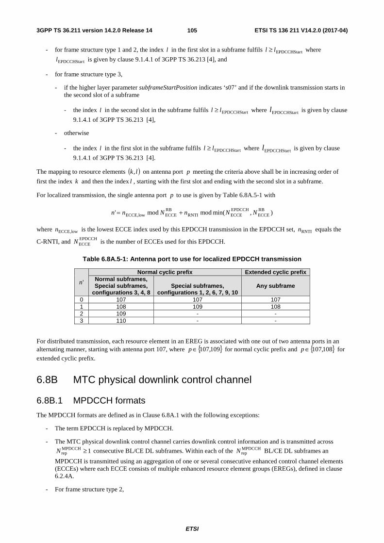
3GPP TS 36.211 version 14.2.0 Release 14 ETSI TS 136 211 V14.2.0 (2017-04)
ETSI
105
- for frame structure type 1 and 2, the index l in the first slot in a subframe fulfils tEPDCCHStarll ≥ where
tEPDCCHStarl is given by clause 9.1.4.1 of 3GPP TS 36.213 [4], and
- for frame structure type 3,
- if the higher layer parameter subframeStartPosition indicates ‘s07’ and if the downlink transmission starts in the second slot of a subframe
- the index l in the second slot in the subframe fulfils tEPDCCHStarll ≥ where tEPDCCHStarl is given by clause
9.1.4.1 of 3GPP TS 36.213 [4],
- otherwise
- the index l in the first slot in the subframe fulfils tEPDCCHStarll ≥ where tEPDCCHStarl is given by clause
9.1.4.1 of 3GPP TS 36.213 [4].
The mapping to resource elements ( )lk, on antenna port p meeting the criteria above shall be in increasing order of
first the index k and then the index l , starting with the first slot and ending with the second slot in a subframe.
For localized transmission, the single antenna port p to use is given by Table 6.8A.5-1 with
),min(modmod' RBECCE
EPDCCHECCERNTI
RBECCElowECCE, NNnNnn +=
where lowECCE,n is the lowest ECCE index used by this EPDCCH transmission in the EPDCCH set, RNTIn equals the
C-RNTI, and EPDCCHECCEN is the number of ECCEs used for this EPDCCH.
Table 6.8A.5-1: Antenna port to use for localized EPDCCH transmission
'n
Normal cyclic prefix Extended cyclic prefix Normal subframes, Special subframes,
configurations 3, 4, 8
Special subframes,
configurations 1, 2, 6, 7, 9, 10 Any subframe
0 107 107 107 1 108 109 108 2 109 - - 3 110 - -
For distributed transmission, each resource element in an EREG is associated with one out of two antenna ports in an alternating manner, starting with antenna port 107, where { }109,107∈p for normal cyclic prefix and { }108,107∈p for
extended cyclic prefix.
6.8B MTC physical downlink control channel
6.8B.1 MPDCCH formats
The MPDCCH formats are defined as in Clause 6.8A.1 with the following exceptions:
- The term EPDCCH is replaced by MPDCCH.
- The MTC physical downlink control channel carries downlink control information and is transmitted across
1MPDCCHrep ≥N consecutive BL/CE DL subframes. Within each of the MPDCCH
repN BL/CE DL subframes an
MPDCCH is transmitted using an aggregation of one or several consecutive enhanced control channel elements (ECCEs) where each ECCE consists of multiple enhanced resource element groups (EREGs), defined in clause 6.2.4A.
- For frame structure type 2,

3GPP TS 36.211 version 14.2.0 Release 14 ETSI TS 136 211 V14.2.0 (2017-04)
ETSI
106
- If repetition is not configured for the MPDCCH, the number of EREGs per ECCE is given by Table 6.8A.1-1. If repetition is configured for the MPDCCH, the number of EREGs per ECCE is given by Table 6.8B.1-1.
- For those special subframes where the MPDCCH is not supported, these special subframes are considered BL/CE DL subframes for both MPDCCH and PDSCH transmission, only if they are indicated as BL/CE DL subframe by higher layer signalling.
- For an MPDCCH associated with 2 or 4 PRBs, if repetition is not configured for the MPDCCH, the supported MPDCCH formats are given by Table 6.8A.1-2. Otherwise, the supported MPDCCH formats are given by Table 6.8B.1-2. However, for MPDCCH format 5, the equation defining the relation between ECCE index and EREG index does not apply and the number of ECCEs refers to the MPDCCH mapping to the REs of the 2+4 PRB set as defined in Subclause 6.8B.5.
Table 6.8B.1-1: Number of EREGs per ECCE, ECCEEREGN , for frame structure type 2.
Normal cyclic prefix Extended cyclic prefix
Normal subframe Special subframe, configuration 3, 4, 8 Normal subframe Special subframe,
configuration 1, 2, 3, 5, 6 4 8
Table 6.8B.1-2: Supported MPDCCH formats
MPDCCH format
Number of ECCEs in a subframe for one MPDCCH, MPDCCHECCEN
ECCEEREGN =4
ECCEEREGN =8
Localized transmission
Distributed transmission
Localized transmission
Distributed transmission
0 2 2 1 1 1 4 4 2 2 2 8 8 4 4 3 16 16 8 8 4 - - - - 5 24 24 12 12
6.8B.2 Scrambling
Scrambling shall be perfomed according to Clause 6.8A.2 with EPDCCH replaced by MPDCCH except that the same scrambling sequence is applied per subframe to MPDCCH for a given block of accN subframes and m is the
MPDCCH set number. For MPDCCH format 5, 0=m is used to generate the scrambling sequence for mapping to REs in 6 PRBs.
For the thj block of accN subframes, the scrambling sequence generator shall be initialised with
( )[ ]( )[ ]⎪⎩
⎪⎨⎧
+⋅++⋅+
=otherwise210mod
common-Type2 Common,-Type1for 210modMPDCCH
,ID9
acc0
cellID
9acc0
initmnNjj
NNjjc
where
( )⎣ ⎦
⎩⎨⎧
=−=
=
+=
−⎥⎥⎦
⎥
⎢⎢⎣
⎢ −++=
Δ
Δ
Δ
10 and 2 typestructure framefor ,2
1or 1 typestructure framefor 0,
1,...,1,0
accacc
acc
acc00
0acc
MPDCCHabs0
NN
Ni
Niij
jN
iNij
3GPP TS 36.211 version 14.2.0 Release 14 ETSI TS 136 211 V14.2.0 (2017-04)
ETSI
107
and 0i is the absolute subframe number of the first downlink subframe intended for the MPDCCH. The MPDCCH
transmission spans MPDCCHabsN consecutive subframes, including non-BL/CE DL subframes where the MPDCCH
transmission is postponed.
For BL/CE UEs,
- if the MPDCCH transmission is associated with P-RNTI or SC-RNTI:
- 4acc =N for frame structure type 1 and 10acc =N for frame structure type 2
- otherwise
- 1acc =N for UEs assuming CEModeA (according to the definition in Clause 12 of [4]) or configured with
CEModeA:
- 4acc =N for frame structure type 1 and 10acc =N for frame structure type 2 for UEs assuming CEModeB
(according to the definition in Clause 12 of [4]) or configured with CEModeB.
6.8B.3 Modulation
Modulation shall be performed according to 6.8A.3 with EPDCCH replaced by MPDCCH.
6.8B.4 Layer mapping and precoding
Layer mapping and precoding shall be done according to Clause 6.8A.4 with EPDCCH replaced by MPDCCH.
6.8B.5 Mapping to resource elements
Mapping to resource elements shall be done according to Clause 6.8A.5with the following exceptions:
- The term EPDCCH shall be replaced by MPDCCH.
- The mapping shall be repeated across each of the MPDCCHrepN BL/CE DL subframes.
- MPDCCHECCEN is the number of ECCEs used for this MPDCCH in the first of the MPDCCH
repN subframes.
- For an MPDCCH associated with a 2+4 PRB set as defined in [4], the mapping to resource elements ( )lk, on
antenna port p shall be in increasing order of first the index k and then the index l over the 6 PRBs for
MPDCCH format 5 and over the 2 or 4 PRBs for the other MPDCCH formats.
- For localized transmission and MPDCCH format 5, the single antenna port p to use is given by Table 6.8A.5-1
with
RBECCERNTI mod' Nnn =
- Resource elements occupied by CSI reference signals shall be counted in the MPDCCH mapping but not used for transmission of the MPDCCH.
- The UE may assume there is no MPDCCH transmission which uses overlapping sets of subframes as PDSCH transmissions to that UE, where the MPDCCH is located at a different narrowband than the PDSCH.
- For BL/CE UEs in CEModeB, in MBSFN subframe(s), resource elements that correspond to the positions of cell-specific reference signals as in subframe #0 shall not be counted in the MPDCCH mapping and not used for transmission of the MPDCCH.
- Resource elements belonging to synchronization signals, the core part of PBCH, PBCH repetitions, or resource elements reserved for reference signals in the mapping operation of PBCH but not used for transmission of reference signals, shall be counted in the MPDCCH mapping but not used for transmission of the MPDCCH.
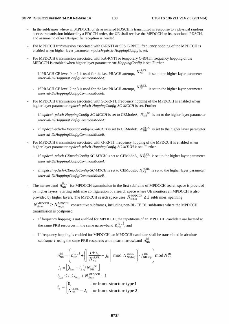
3GPP TS 36.211 version 14.2.0 Release 14 ETSI TS 136 211 V14.2.0 (2017-04)
ETSI
108
- In the subframes where an MPDCCH or its associated PDSCH is transmitted in response to a physical random access transmission initiated by a PDCCH order, the UE shall receive the MPDCCH or its associated PDSCH, and assume no other UE-specific reception is needed.
- For MPDCCH transmission associated with C-RNTI or SPS C-RNTI, frequency hopping of the MPDCCH is enabled when higher layer parameter mpdcch-pdsch-HoppingConfig is set.
- For MPDCCH transmission associated with RA-RNTI or temporary C-RNTI, frequency hopping of the MPDCCH is enabled when higher layer parameter rar-HoppingConfig is set. Further
- if PRACH CE level 0 or 1 is used for the last PRACH attempt, DLch,
NBN is set to the higher layer parameter interval-DlHoppingConfigCommonModeA;
- if PRACH CE level 2 or 3 is used for the last PRACH attempt, DLch,
NBN is set to the higher layer parameter interval-DlHoppingConfigCommonModeB.
- For MPDCCH transmission associated with SC-RNTI, frequency hopping of the MPDCCH is enabled when higher layer parameter mpdcch-pdsch-HoppingConfig-SC-MCCH is set. Further
- if mpdcch-pdsch-HoppingConfig-SC-MCCH is set to CEModeA, DLch,NBN is set to the higher layer parameter
interval-DlHoppingConfigCommonModeA;
- if mpdcch-pdsch-HoppingConfig-SC-MCCH is set to CEModeB, DLch,NBN is set to the higher layer parameter
interval-DlHoppingConfigCommonModeB.
- For MPDCCH transmission associated with G-RNTI, frequency hopping of the MPDCCH is enabled when higher layer parameter mpdcch-pdsch-HoppingConfig-SC-MTCH is set. Further
- if mpdcch-pdsch-CEmodeConfig-SC-MTCH is set to CEModeA, DLch,NBN is set to the higher layer parameter
interval-DlHoppingConfigCommonModeA;
- if mpdcch-pdsch-CEmodeConfig-SC-MTCH is set to CEModeB, DLch,NBN is set to the higher layer parameter
interval-DlHoppingConfigCommonModeB.
- The narrowband ( )ssin ,0
NB for MPDCCH transmission in the first subframe of MPDCCH search space is provided
by higher layers. Starting subframe configuration of a search space where UE monitors an MPDCCH is also
provided by higher layers. The MPDCCH search space uses 1MPDCCHssrep, ≥N subframes, spanning
MPDCCHssrep,
MPDCCHssabs, NN ≥ consecutive subframes, including non-BL/CE DL subframes where the MPDCCH
transmission is postponed.
- If frequency hopping is not enabled for MPDCCH, the repetitions of an MPDCCH candidate are located at
the same PRB resources in the same narrowband ( )ssin ,0
NB , and
- if frequency hopping is enabled for MPDCCH, an MPDCCH candidate shall be transmitted in absolute
subframe i using the same PRB resources within each narrowband ( )inNB
( ) ( )
( )⎣ ⎦
⎩⎨⎧
−=
−+≤≤
+=
⎟⎟
⎠
⎞
⎜⎜
⎝
⎛⋅⎟⎟
⎠
⎞⎜⎜⎝
⎛⎥⎦
⎥⎢⎣
⎢−++=
Δ
Δ
Δ
2 typestructure framefor ,2
1 typestructure framefor 0,
1
modmod
DLch,NB
MPDCCHssabs,,0,0
DLch,NB,00
DLNB
DLhopNB,
DLch,hopNB,0DLch,
NBNBNB
,0
Ni
Niii
Niij
Nf N jN
iinn
ssss
ss
ii ss

3GPP TS 36.211 version 14.2.0 Release 14 ETSI TS 136 211 V14.2.0 (2017-04)
ETSI
109
where ssi ,0 is the absolute subframe number of the first downlink subframe of MPDCCH search space, and
DLch,hopNB,N , DLch,
NBN and DLhopNB,f are cell-specific higher-layer parameters. The UE shall not expect MPDCCH
transmission in absolute subframe i if it is not a BL/CE DL subframe.
- The UE may assume the same precoding matrix being used for a PRB across a block of DLch,NBN consecutive
subframes for MPDCCH.
The UE may assume that an MPDCCH associated with the P-RNTI is transmitted on the set { }js of narrowbands where
{ }js is defined in Subclause 6.4.1. For a UE monitoring an MPDCCH associated with the P-RNTI, the first MPDCCH
narrowband is given by ms where ( ) SNB
cellID
pNB mod
~NNNm += , { }1,...,1,0
~ pNB
pNB −∈ NN is the Paging Narrowband (PN)
obtained according to [10], and PNBN is the higher-layer parameter paging-narrowBands.
- If the higher-layer parameter si-HoppingConfigCommon disables frequency hopping for an MPDCCH associated with P-RNTI, each MPDCCH candidate shall be located in the same PRB in narrowband ms where
( ) SNB
cellID
pNB mod
~NNNm += .
- If the higher-layer parameter si-HoppingConfigCommon enables frequency hopping for an MPDCCH with P-RNTI, an MPDCCH candidate shall be located in narrowband js in absolute subframe i using the same PRB
resources within each narrowband js where
( )p cell ch,DL DL SNB ID 0 NB,hop NB,hop NBch,DL
NB
mod modi i
j N N j N f NN
Δ⎛ ⎞⎛ ⎞⎢ ⎥+= + + − ⋅⎜ ⎟⎜ ⎟⎢ ⎥⎜ ⎟⎜ ⎟⎣ ⎦⎝ ⎠⎝ ⎠
%
( )⎣ ⎦
⎩⎨⎧
−=
−+≤≤
+=
Δ
Δ
2 typestructure framefor ,2
1 typestructure framefor 0,
1
DLch,NB
MPDCCHssabs,,0,0
DLch,NB,00
Ni
Niii
Niij
ssss
ss
where ssi ,0 is the absolute subframe number of the first downlink subframe of MPDCCH search space according
to locations of paging opportunity subframes, and DLch,hopNB,N , DLch,
NBN and DLhopNB,f are cell-specific higher-layer
parameters. For MPDCCH associated with P-RNTI, if interval-DlHoppingConfigCommonModeB is signalled in
SIB1-BR, then the frequency hopping granularity DLch,NBN is set to interval-DlHoppingConfigCommonModeB;
otherwise, DLch,NBN is set to interval-DlHoppingConfigCommonModeA signalled in SIB1-BR.
The UE shall not expect MPDCCH transmission in absolute subframe i if it is not a BL/CE DL subframe.
6.9 Physical hybrid ARQ indicator channel The PHICH carries the hybrid-ARQ ACK/NACK. Multiple PHICHs mapped to the same set of resource elements constitute a PHICH group, where PHICHs within the same PHICH group are separated through different orthogonal
sequences. A PHICH resource is identified by the index pair ( )seqPHICH
groupPHICH , nn , where group
PHICHn is the PHICH group
number and seqPHICHn is the orthogonal sequence index within the group.
For frame structure type 1 and type 3, the number of PHICH groups groupPHICHN is constant in all subframes and given by

3GPP TS 36.211 version 14.2.0 Release 14 ETSI TS 136 211 V14.2.0 (2017-04)
ETSI
110
( )⎡ ⎤( )⎡ ⎤⎪⎩
⎪⎨
⎧
⋅=
prefix cyclic extendedfor 82
prefix cyclic normalfor 8
DLRBg
DLRBggroup
PHICHNN
NNN
where { }2,1,21,61g ∈N is provided by higher layers. The index groupPHICHn ranges from 0 to 1group
PHICH −N .
For frame structure type 2, the number of PHICH groups may vary between subframes and is given by groupPHICHNmi ⋅
where groupPHICHN is given by the expression above and im is given by Table 6.9-1 with the uplink-downlink configuration
provided by the higher-layer parameter subframeAssignment. The index groupPHICHn in a subframe with non-zero PHICH
resources ranges from 0 to 1groupPHICH −⋅ Nmi .
Table 6.9-1: The factor im for frame structure type 2
Uplink-downlink configuration
Subframe number i 0 1 2 3 4 5 6 7 8 9
0 2 1 0 0 0 2 1 0 0 0 1 0 1 0 0 1 0 1 0 0 1 2 0 0 0 1 0 0 0 0 1 0 3 1 0 0 0 0 0 0 0 1 1 4 0 0 0 0 0 0 0 0 1 1 5 0 0 0 0 0 0 0 0 1 0 6 1 1 0 0 0 1 1 0 0 1
6.9.1 Modulation
The block of bits )1(),...,0( bit −Mbb transmitted on one PHICH in one subframe shall be modulated as described in
clause 7.1, resulting in a block of complex-valued modulation symbols )1(),...,0( s −Mzz , where bits MM = . Table
6.9.1-1 specifies the modulation mappings applicable for the physical hybrid ARQ indicator channel.
Table 6.9.1-1: PHICH modulation schemes.
Physical channel Modulation schemes PHICH BPSK
The block of modulation symbols )1(),...,0( s −Mzz shall be symbol-wise multiplied with an orthogonal sequence and
scrambled, resulting in a sequence of modulation symbols )1(),...,0( symb −Mdd according to
( ) ( ) ⎣ ⎦( )PHICHSF
PHICHSF )(21mod)( NizicNiwid ⋅−⋅=
where
⎩⎨⎧
=
⋅=
−=
prefix cyclic extended2
prefix cyclic normal4
1,...,0
PHICHSF
sPHICHSFsymb
symb
N
MNM
Mi
and )(ic is a cell-specific scrambling sequence generated according to clause 7.2. The scrambling sequence generator
shall be initialised with ⎣ ⎦( ) ( ) cellID
9cellIDsinit 21212 NNnc +⋅+⋅+= at the start of each subframe.
The sequence [ ])1()0( PHICHSF −Nww L is given by Table 6.9.1-2 where the sequence index seq
PHICHn corresponds to
the PHICH number within the PHICH group.

3GPP TS 36.211 version 14.2.0 Release 14 ETSI TS 136 211 V14.2.0 (2017-04)
ETSI
111
Table 6.9.1-2: Orthogonal sequences [ ])1()0( PHICHSF −Nww L for PHICH
Sequence index Orthogonal sequence
seqPHICHn
Normal cyclic prefix
4PHICHSF =N
Extended cyclic prefix
2PHICHSF =N
0 [ ]1111 ++++ [ ]11 ++
1 [ ]1111 −+−+ [ ]11 −+
2 [ ]1111 −−++ [ ]jj ++
3 [ ]1111 +−−+ [ ]jj −+
4 [ ]jjjj ++++ -
5 [ ]jjjj −+−+ -
6 [ ]jjjj −−++ -
7 [ ]jjjj +−−+ -
6.9.2 Resource group alignment, layer mapping and precoding
The block of symbols )1(),...,0( symb −Mdd should be first aligned with resource element group size, resulting in a
block of symbols )1(),...,0( symb)0()0( −⋅ Mcdd , where 1=c for normal cyclic prefix; and 2=c for extended cyclic
prefix.
For normal cyclic prefix, )()()0( idid = , for 1,...,0 symb −= Mi .
For extended cyclic prefix,
[ ] [ ][ ]⎪⎩
⎪⎨⎧
=+=+=+++
12mod)12()2(00
02mod00)12()2()34()24()14()4(
groupPHICH
groupPHICH)0()0()0()0(
nidid
nidididididid T
TT
for ( ) 12,...,0 symb −= Mi .
The block of symbols )1(),...,0( symb)0()0( −⋅ Mcdd shall be mapped to layers and precoded, resulting in a block of
vectors [ ]TP iyiyiy )(...)()( )1()0( −= , 1,...,0 symb −⋅= Mci , where )()( iy p represents the signal for antenna port p ,
1,...,0 −= Pp and the number of cell-specific reference signals { }4,2,1∈P . The layer mapping and precoding operation
depends on the cyclic prefix length and the number of antenna ports used for transmission of the PHICH. The PHICH shall be transmitted on the same set of antenna ports as the PBCH.
For transmission on a single antenna port, 1=P , layer mapping and precoding are defined by clauses 6.3.3.1 and
6.3.4.1, respectively, with symb(0)symb McM ⋅= .
For transmission on two antenna ports, 2=P , layer mapping and precoding are defined by clauses 6.3.3.3 and 6.3.4.3,
respectively, with symb(0)symb McM ⋅= .
For transmission on four antenna ports, 4=P , layer mapping is defined by clause 6.3.3.3 with symb(0)symb McM ⋅= and
precoding by
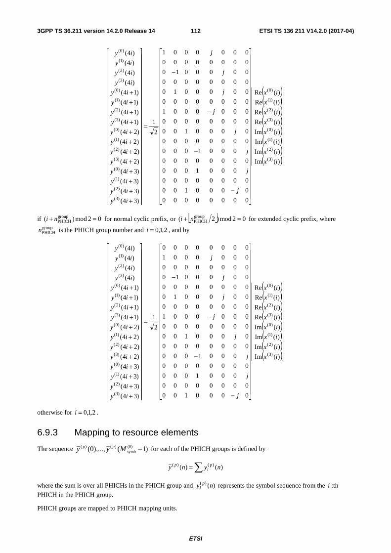
3GPP TS 36.211 version 14.2.0 Release 14 ETSI TS 136 211 V14.2.0 (2017-04)
ETSI
112
( )( )( )( )( )( )( )( )⎥⎥
⎥⎥⎥⎥⎥⎥⎥⎥⎥
⎦
⎤
⎢⎢⎢⎢⎢⎢⎢⎢⎢⎢⎢
⎣
⎡
⎥⎥⎥⎥⎥⎥⎥⎥⎥⎥⎥⎥⎥⎥⎥⎥⎥⎥⎥⎥⎥⎥⎥
⎦
⎤
⎢⎢⎢⎢⎢⎢⎢⎢⎢⎢⎢⎢⎢⎢⎢⎢⎢⎢⎢⎢⎢⎢⎢
⎣
⎡
−
−
−
−
=
⎥⎥⎥⎥⎥⎥⎥⎥⎥⎥⎥⎥⎥⎥⎥⎥⎥⎥⎥⎥⎥⎥⎥⎥
⎦
⎤
⎢⎢⎢⎢⎢⎢⎢⎢⎢⎢⎢⎢⎢⎢⎢⎢⎢⎢⎢⎢⎢⎢⎢⎢
⎣
⎡
++++++++++++
)(Im
)(Im
)(Im
)(Im
)(Re
)(Re
)(Re
)(Re
00000000
0000100
00000000
0001000
00000000
0001000
00000000
0000100
00000000
0000001
00000000
0000010
00000000
0000010
00000000
0000001
2
1
)34(
)34(
)34(
)34(
)24(
)24(
)24(
)24(
)14(
)14(
)14(
)14(
)4(
)4(
)4(
)4(
)3(
)2(
)1(
)0(
)3(
)2(
)1(
)0(
)3(
)2(
)1(
)0(
)3(
)2(
)1(
)0(
)3(
)2(
)1(
)0(
)3(
)2(
)1(
)0(
ix
ix
ix
ix
ix
ix
ix
ix
j
j
j
j
j
j
j
j
iy
iy
iy
iy
iy
iy
iy
iy
iy
iy
iy
iy
iy
iy
iy
iy
if 02mod)( groupPHICH =+ ni for normal cyclic prefix, or ⎣ ⎦ 02mod)2( group
PHICH =+ ni for extended cyclic prefix, where groupPHICHn is the PHICH group number and 2,1,0=i , and by
( )( )( )( )( )( )( )( )⎥⎥
⎥⎥⎥⎥⎥⎥⎥⎥⎥
⎦
⎤
⎢⎢⎢⎢⎢⎢⎢⎢⎢⎢⎢
⎣
⎡
⎥⎥⎥⎥⎥⎥⎥⎥⎥⎥⎥⎥⎥⎥⎥⎥⎥⎥⎥⎥⎥⎥⎥
⎦
⎤
⎢⎢⎢⎢⎢⎢⎢⎢⎢⎢⎢⎢⎢⎢⎢⎢⎢⎢⎢⎢⎢⎢⎢
⎣
⎡
−
−
−
−
=
⎥⎥⎥⎥⎥⎥⎥⎥⎥⎥⎥⎥⎥⎥⎥⎥⎥⎥⎥⎥⎥⎥⎥⎥
⎦
⎤
⎢⎢⎢⎢⎢⎢⎢⎢⎢⎢⎢⎢⎢⎢⎢⎢⎢⎢⎢⎢⎢⎢⎢⎢
⎣
⎡
++++++++++++
)(Im
)(Im
)(Im
)(Im
)(Re
)(Re
)(Re
)(Re
0000100
00000000
0001000
00000000
0001000
00000000
0000100
00000000
0000001
00000000
0000010
00000000
0000010
00000000
0000001
00000000
2
1
)34(
)34(
)34(
)34(
)24(
)24(
)24(
)24(
)14(
)14(
)14(
)14(
)4(
)4(
)4(
)4(
)3(
)2(
)1(
)0(
)3(
)2(
)1(
)0(
)3(
)2(
)1(
)0(
)3(
)2(
)1(
)0(
)3(
)2(
)1(
)0(
)3(
)2(
)1(
)0(
ix
ix
ix
ix
ix
ix
ix
ix
j
j
j
j
j
j
j
j
iy
iy
iy
iy
iy
iy
iy
iy
iy
iy
iy
iy
iy
iy
iy
iy
otherwise for 2,1,0=i .
6.9.3 Mapping to resource elements
The sequence )1(),...,0( (0)symb
)()( −Myy pp for each of the PHICH groups is defined by
∑= )()( )()( nyny pi
p
where the sum is over all PHICHs in the PHICH group and )()( ny pi represents the symbol sequence from the i :th
PHICH in the PHICH group.
PHICH groups are mapped to PHICH mapping units.
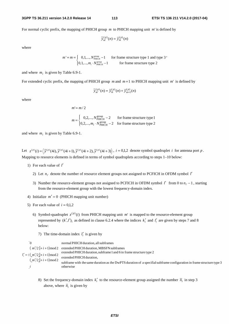
3GPP TS 36.211 version 14.2.0 Release 14 ETSI TS 136 211 V14.2.0 (2017-04)
ETSI
113
For normal cyclic prefix, the mapping of PHICH group m to PHICH mapping unit 'm is defined by
)()(~ )()(' nyny p
mp
m =
where
groupPHICH
groupPHICH
' 0,1,..., 1 for frame structure type 1 and type 3
0,1,..., 1 for frame structure type 2i
m m N
m N
⎧= = −⎨ ⋅ −⎩
,
and where im is given by Table 6.9-1.
For extended cyclic prefix, the mapping of PHICH group m and 1+m to PHICH mapping unit 'm is defined by
)()()(~ )(1
)()(' nynyny p
mp
mp
m ++=
where
2/' mm =
⎪⎩
⎪⎨⎧
−⋅−=
2 typestructure framefor 2,...,2,0
1 typestructure framefor 2,...,2,0groupPHICH
groupPHICH
Nm
Nm
i
and where im is given by Table 6.9-1.
Let )34(~),24(~),14(~),4(~)( )()()()()( +++= iyiyiyiyiz ppppp , 2,1,0=i denote symbol quadruplet i for antenna port p .
Mapping to resource elements is defined in terms of symbol quadruplets according to steps 1–10 below:
1) For each value of l′
2) Let ln ′ denote the number of resource element groups not assigned to PCFICH in OFDM symbol l′
3) Number the resource-element groups not assigned to PCFICH in OFDM symbol l′ from 0 to 1ln ′ − , starting
from the resource-element group with the lowest frequency-domain index.
4) Initialize 0=′m (PHICH mapping unit number)
5) For each value of 2,1,0=i
6) Symbol-quadruplet )()( iz p from PHICH mapping unit 'm is mapped to the resource-element group
represented by ilk ),( ′′ as defined in clause 6.2.4 where the indices ik ′ and il′ are given by steps 7 and 8
below:
7) The time-domain index il′ is given by
⎣ ⎦( )⎣ ⎦( )⎣ ⎦( )
⎪⎪⎪
⎩
⎪⎪⎪
⎨
⎧
++′++′
++′
=′
otherwise3 typestructure framein ion configurat subframe specifial a ofduration DwPTS theasduration same with thesubframe
duration, PHICH extended
2 typestructure framein 6 and 1 subframe duration, PHICH extended
2mod12
2mod12
subframes MBSFN duration, PHICH extended2mod12
subframes all duration, PHICH normal0
i
im
im
im
li
8) Set the frequency-domain index ik ′ to the resource-element group assigned the number in in step 3
above, where in is given by

3GPP TS 36.211 version 14.2.0 Release 14 ETSI TS 136 211 V14.2.0 (2017-04)
ETSI
114
⎣ ⎦( )⎣ ⎦ ⎣ ⎦( )⎣ ⎦ ⎣ ⎦( )⎪
⎪
⎩
⎪⎪
⎨
⎧
=++⋅
=++⋅
=+⋅
=
′′′
′′′
′′
2mod32'
1mod3'
0mod'
1cellID
1cellID
1cellID
innmnnN
innmnnN
inmnnN
n
iii
iii
ii
lll
lll
ll
i
in case of extended PHICH duration in MBSFN subframes, or extended PHICH duration in subframes 1 and 6 for frame structure type 2, or extended PHICH duration in subframe with the same duration as the DwPTS duration of a special subframe configuration in frame structure type 3 and by
⎣ ⎦( )⎣ ⎦ ⎣ ⎦( )⎣ ⎦ ⎣ ⎦( )⎪
⎪
⎩
⎪⎪
⎨
⎧
=++⋅
=++⋅
=+⋅
=
′′′
′′′
′′
2mod32'
1mod3'
0mod'
0cellID
0cellID
0cellID
innmnnN
innmnnN
inmnnN
n
iii
iii
ii
lll
lll
ll
i
otherwise.
9) Increase m′ by 1.
10) Repeat from step 5 until all PHICH mapping units have been assigned.
The PHICH duration is configurable by higher layers according to Table 6.9.3-1.
The PHICH shall not be transmitted in MBSFN subframes with zero-size non-MBSFN region.
Table 6.9.3-1: PHICH duration in MBSFN and non-MBSFN subframes
PHICH duration
Non-MBSFN subframes
MBSFN subframes
Subframes 1 and 6 in case of frame structure type 2
Subframe with the same duration as the DwPTS duration of a specifial
subframe configuration in case of frame structure type
3
All other cases
Normal 1 1 1 1 Extended 2 2 3 2
6.10 Reference signals Six types of downlink reference signals are defined:
- Cell-specific Reference Signal (CRS)
- MBSFN reference signal
- UE-specific Reference Signal (DM-RS) associated with PDSCH
- DeModulation Reference Signal (DM-RS) associated with EPDCCH or MPDCCH
- Positioning Reference Signal (PRS)
- CSI Reference Signal (CSI-RS)
There is one reference signal transmitted per downlink antenna port.
6.10.1 Cell-specific Reference Signal (CRS)
The UE may assume cell-specific reference signals are, unless otherwise stated in [4, clause 12], transmitted in
- all downlink subframes for frame structure type 1,
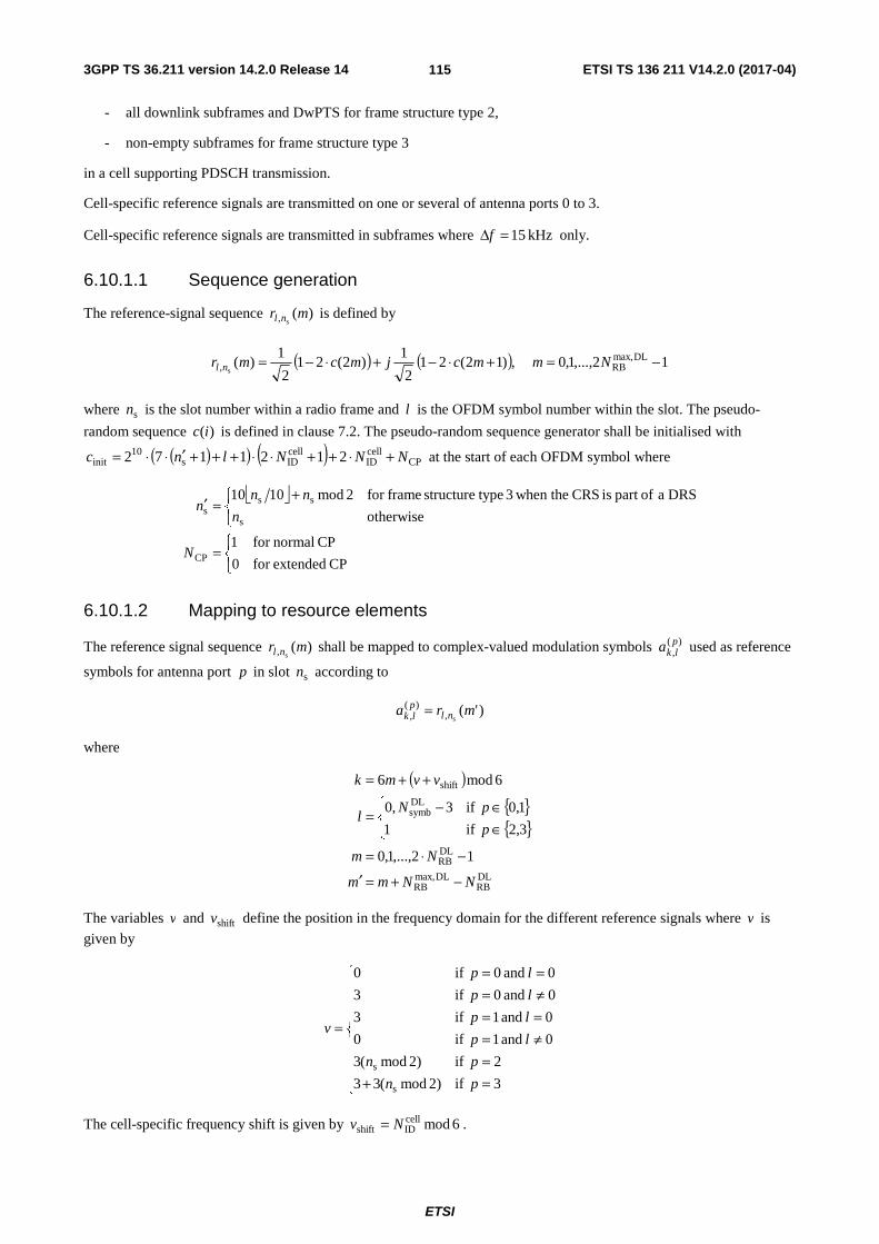
3GPP TS 36.211 version 14.2.0 Release 14 ETSI TS 136 211 V14.2.0 (2017-04)
ETSI
115
- all downlink subframes and DwPTS for frame structure type 2,
- non-empty subframes for frame structure type 3
in a cell supporting PDSCH transmission.
Cell-specific reference signals are transmitted on one or several of antenna ports 0 to 3.
Cell-specific reference signals are transmitted in subframes where kHz 15=Δf only.
6.10.1.1 Sequence generation
The reference-signal sequence )(s, mr nl is defined by
( ) ( ) 12,...,1,0 ,)12(212
1)2(21
2
1)( DLmax,
RB, s−=+⋅−+⋅−= Nmmcjmcmr nl
where sn is the slot number within a radio frame and l is the OFDM symbol number within the slot. The pseudo-
random sequence )(ic is defined in clause 7.2. The pseudo-random sequence generator shall be initialised with
( )( ) ( ) CPcellID
cellIDs
10init 2121172 NNNlnc +⋅++⋅⋅+++′⋅⋅= at the start of each OFDM symbol where
⎣ ⎦
⎩⎨⎧
=
⎩⎨⎧ +
=′
CP extendedfor 0
CP normalfor 1
otherwise
DRS a ofpart is CRS when the3 typestructure framefor 2mod1010
CP
s
sss
N
n
nnn
6.10.1.2 Mapping to resource elements
The reference signal sequence )(s, mr nl shall be mapped to complex-valued modulation symbols )(
,plka used as reference
symbols for antenna port p in slot sn according to
)'(s,
)(, mra nlplk =
where
( ){ }{ }
DLRB
DLmax,RB
DLRB
DLsymb
shift
12,...,1,0
3,2 if1
1,0 if3,0
6mod6
NNmm
Nm
p
pNl
vvmk
−+=′
−⋅=
⎪⎩
⎪⎨⎧
∈∈−=
++=
The variables v and shiftv define the position in the frequency domain for the different reference signals where v is
given by
⎪⎪⎪⎪
⎩
⎪⎪⎪⎪
⎨
⎧
=+=
≠===≠===
=
3 if)2mod(33
2 if)2mod(3
0 and 1 if0
0 and 1 if3
0 and 0 if3
0 and 0 if0
s
s
pn
pn
lp
lp
lp
lp
v
The cell-specific frequency shift is given by 6modcellIDshift Nv = .

3GPP TS 36.211 version 14.2.0 Release 14 ETSI TS 136 211 V14.2.0 (2017-04)
ETSI
116
Resource elements ( )lk, used for transmission of cell-specific reference signals on any of the antenna ports in a slot
shall not be used for any transmission on any other antenna port in the same slot and set to zero.
In an MBSFN subframe, cell-specific reference signals shall only be transmitted in the non-MBSFN region of the MBSFN subframe.
Figures 6.10.1.2-1 and 6.10.1.2-2 illustrate the resource elements used for reference signal transmission according to the above definition. The notation pR is used to denote a resource element used for reference signal transmission on
antenna port p .
0=l
0R
0R
0R
0R
6=l 0=l
0R
0R
0R
0R
6=l
One antenna port
Two antenna ports
0=l
0R
0R
0R
0R
6=l 0=l
0R
0R
0R
0R
6=l 0=l
1R
1R
1R
6=l 0=l
1R
1R
1R
1R
6=l
0=l
0R
0R
0R
0R
6=l 0=l
0R
0R
0R
0R
6=l 0=l
1R
1R
1R
1R
6=l 0=l
1R
1R
1R
1R
6=l
Four antenna ports
0=l 6=l 0=l
2R
6=l 0=l 6=l 0=l 6=l
2R
2R
2R
3R
3R
3R
3R
Figure 6.10.1.2-1. Mapping of downlink reference signals (normal cyclic prefix)

3GPP TS 36.211 version 14.2.0 Release 14 ETSI TS 136 211 V14.2.0 (2017-04)
ETSI
117
0=l
0R
0R
0R
0R
5=l 0=l
0R
0R
0R
0R
5=l
One antenna port
Two antenna ports
Resource element (k,l)
Not used for transmission on this antenna port
Reference symbols on this antenna port
0=l
0R
0R
0R
0R
5=l 0=l
0R
0R
0R
0R
5=l 0=l
1R
1R
1R
1R
5=l 0=l
1R
1R
1R
1R
5=l
0=l
0R
0R
0R
0R
5=l 0=l
0R
0R
0R
0R
5=l 0=l
1R
1R
1R
1R
5=l 0=l
1R
1R
1R
1R
5=l
Four antenna ports
0=l 5=l 0=l
2R
5=l 0=l 5=l 0=l 5=l
2R
2R
2R
3R
3R
3R
3R
even-numbered slots odd-numbered slots
Antenna port 0 Antenna port 1 Antenna port 2 Antenna port 3
even-numbered slots odd-numbered slots even-numbered slots odd-numbered slots even-numbered slots odd-numbered slots
Figure 6.10.1.2-2. Mapping of downlink reference signals (extended cyclic prefix)
6.10.2 MBSFN reference signals
MBSFN reference signals shall be transmitted in the MBSFN region of MBSFN subframes only when the PMCH is transmitted. MBSFN reference signals are transmitted on antenna port 4.
MBSFN reference signals are defined for extended cyclic prefix only.
6.10.2.1 Sequence generation
6.10.2.1.1 Sequence generation for 15 kHz and 7.5 kHz subcarrier spacing
The MBSFN reference-signal sequence )(s, mr nl is defined by
( ) ( ) 16,...,1,0 ,)12(212
1)2(21
2
1)( DLmax,
RB, s−=+⋅−+⋅−= Nmmcjmcmr nl
where sn is the slot number within a radio frame and l is the OFDM symbol number within the slot. The pseudo-
random sequence )(ic is defined in clause 7.2. The pseudo-random sequence generator shall be initialised with
( )( ) ( ) MBSFNID
MBSFNID
9init 121172 NNlnc s ++⋅⋅+++⋅⋅= at the start of each OFDM symbol.
6.10.2.1.2 Sequence generation for 1.25 kHz subcarrier spacing
The MBSFN reference-signal sequence )(sf, mr nl is defined by

3GPP TS 36.211 version 14.2.0 Release 14 ETSI TS 136 211 V14.2.0 (2017-04)
ETSI
118
( ) ( ) 124,...,1,0 ,)12(212
1)2(21
2
1)( DLmax,
RB, sf−=+⋅−+⋅−= Nmmcjmcmr nl
where sfn is the subframe number within a radio frame and l is the OFDM symbol number within the subframe. The
pseudo-random sequence )(ic is defined in clause 7.2. The pseudo-random sequence generator shall be initialised with
( )( ) ( ) MBSFNID
MBSFNIDsf
9init 121172 NNlnc ++⋅⋅+++⋅⋅= at the start of each OFDM symbol.
6.10.2.2 Mapping to resource elements
6.10.2.2.1 Mapping to resource elements for 15 kHz and 7.5 kHz subcarrier spacing
The reference-signal sequence )(s, mr nl ′ in OFDM symbol l shall be mapped to complex-valued modulation symbols
)(,plka with 4=p according to
)(s,
)(, mra nlplk ′=
where
( )DLRB
DLmax,RB
DLRB
s
s
s
s
3
16,...,1,0
kHz 5.7 and 12mod if2,0
kHz 5.7 and 02mod if1
kHz 15 and 12mod if4,0
kHz 15 and 02mod if2
kHz 5.7 and 0 if24
kHz 5.7 and 0 if4
kHz 15 and 0 if12
kHz 15 and 0 if2
NNmm
Nm
fn
fn
fn
fn
l
flm
flm
flm
flm
k
−+=′
−=
⎪⎪
⎩
⎪⎪
⎨
⎧
=Δ==Δ==Δ==Δ=
=
⎪⎪
⎩
⎪⎪
⎨
⎧
=Δ=+=Δ≠=Δ=+=Δ≠
=
Figure 6.10.2.2-1 illustrates the resource elements used for MBSFN reference signal transmission in case of kHz 15=Δf . In case of kHz 5.7=Δf , the MBSFN reference signal shall be mapped to resource elements according to
Figure 6.10.2.2-3. The notation pR is used to denote a resource element used for reference signal transmission on
antenna port p .

3GPP TS 36.211 version 14.2.0 Release 14 ETSI TS 136 211 V14.2.0 (2017-04)
ETSI
119
0=l 5=l 0=l 5=l4R
4R
4R
4R
4R
4R
4R
4R
4R
4R
4R
4R
4R
4R
4R
4R
4R
4R
Figure 6.10.2.2-1: Mapping of MBSFN reference signals (extended cyclic prefix, kHz 15=Δf )
0=l 2=l 0=l 2=leven-
numbered
slots
Antenna port 4
4R
4R
4R
4R
4R
4R
4R
4R
4R
odd-
numbered
slots
4R
4R
4R
4R
4R
4R
4R
4R
4R
Figure 6.10.2.2-3: Mapping of MBSFN reference signals (extended cyclic prefix, kHz 5.7=Δf )

3GPP TS 36.211 version 14.2.0 Release 14 ETSI TS 136 211 V14.2.0 (2017-04)
ETSI
120
6.10.2.2.1 Mapping to resource elements for 1.25 kHz
The reference-signal sequence )(sf, mr nl ′ in OFDM symbol l shall be mapped to complex-valued modulation symbols
)(,plka with 4=p according to
)(sf,
)(, mra nlplk ′=
where
( )DLRB
DLmax,RB
DLRB
sf
sf
3
124,...,1,0
0
12mod if36
02mod if6
NNmm
Nm
l
nm
nmk
−+=′
−=
=⎩⎨⎧
=+=
=
6.10.3 UE-specific reference signals associated with PDSCH
UE-specific reference signals associated with PDSCH
- are transmitted on antenna port(s) 5=p , 7=p , 8p = , 11p = , 13p = , {11,13}p = or 6,...,8,7 += υp , where
υ is the number of layers used for transmission of the PDSCH;
- are present and are a valid reference for PDSCH demodulation only if the PDSCH transmission is associated with the corresponding antenna port according to clause 7.1 of 3GPP TS 36.213 [4];
- are transmitted only on the physical resource blocks upon which the corresponding PDSCH is mapped.
A UE-specific reference signal associated with PDSCH is not transmitted in resource elements ( )lk, in which one of
the physical channels or physical signals other than the UE-specific reference signals defined in 6.1 are transmitted using resource elements with the same index pair ( )lk, regardless of their antenna port p .
For frame structure type 3, for PDSCH in a subframe with the same duration as the DwPTS duration of a special subframe configuration, the UE-specific reference signals are defined the same as that for the corresponding special subframe configuration.
6.10.3.1 Sequence generation
For antenna port 5, the UE-specific reference-signal sequence )(s
mrn is defined by
( ) ( ) 11210 ,)12(212
1)2(21
2
1)( PDSCH
RBs−=+⋅−+⋅−= N,...,,mmcjmcmrn
where PDSCHRBN denotes the assigned bandwidth in resource blocks of the corresponding PDSCH transmission. The
pseudo-random sequence )(ic is defined in clause 7.2. The pseudo-random sequence generator shall be initialised with
⎣ ⎦( ) ( ) RNTI16cell
IDsinit 21212 nNnc +⋅+⋅+= at the start of each subframe where RNTIn is as described in clause 7.1
3GPP TS 36.213 [4].
For any of the antenna ports }14,...,8,7{∈p , the reference-signal sequence )(mr is defined by
( ) ( )⎪⎩
⎪⎨⎧
−−=+⋅−+⋅−=
prefix cyclic extended11610
prefix cyclic normal11210 ,)12(21
2
1)2(21
2
1)(
DLmax,RB
DLmax,RB
N,...,,
N,...,,mmcjmcmr .
The pseudo-random sequence )(ic is defined in clause 7.2. The pseudo-random sequence generator shall be initialised
with

3GPP TS 36.211 version 14.2.0 Release 14 ETSI TS 136 211 V14.2.0 (2017-04)
ETSI
121
⎣ ⎦( ) ( ) SCID16)(
IDsinit 21212/ SCID nnnc n +⋅+⋅+=
at the start of each subframe.
For BL/CE UEs, the same scrambling sequence is applied per subframe to the UE-specific reference-signal sequence
for a given block of accN subframes. For the thj block of accN subframes, the scrambling sequence generator shall be
initialised with
( )[ ]( ) ( ) SCID16cell
IDacc0init 212110mod nNNjjc +⋅+⋅++=
where
( )⎣ ⎦
⎩⎨⎧
=−=
=
+=
−⎥⎦
⎥⎢⎣
⎢ −++=
Δ
Δ
Δ
10 and 2 typestructure framefor ,2
1or 1 typestructure framefor 0,
1,...,1,0
accacc
acc
acc00
0acc
PDSCHabs0
NN
Ni
Niij
jN
iNij
and 0i is the absolute subframe number of the first downlink subframe intended for PDSCH. The PDSCH transmissions
span PDSCHabsN consecutive subframes, including non-BL/CE DL subframes where the PDSCH transmission is
postponed. For a BL/CE UE configured in CEModeA, 1acc =N . For a BL/CE UE configured with CEModeB,
4acc =N for frame structure type 1 and 10acc =N for frame structure type 2.
The quantities )(IDin , 1,0=i , are given by
- cellID
)(ID Nn i = if no value for inDMRS,
ID is provided by higher layers or if DCI format 1A, 2B or 2C is used for the
DCI associated with the PDSCH transmission
- ii nn DMRS,ID
)(ID = otherwise
The value of SCIDn is zero unless specified otherwise. For a PDSCH transmission on ports 7 or 8, SCIDn is given by the
DCI format 2B, 2C, 2D or 6-1A in 3GPP TS 36.212 [3] associated with the PDSCH transmission. In the case of DCI format 2B, SCIDn is indicated by the scrambling identity field according to Table 6.10.3.1-1. In the
case of DCI format 2C or 2D, SCIDn is given by Table 5.3.3.1.5C-1 or Table 5.3.3.1.5C-2 in 3GPP TS 36.212 [3]. For a
PDSCH transmission on ports 11 or 13, SCIDn is given by the DCI format 2C or 2D in 3GPP TS 36.212 [3] associated
with the PDSCH transmission where SCIDn is given by Table 5.3.3.1.5C-2 in 3GPP TS 36.212 [3].
Table 6.10.3.1-1: Mapping of scrambling identity field in DCI format 2B to SCIDn values for antenna ports 7 and 8
Scrambling identity field in DCI format 2B
(3GPP TS 36.212 [3]) SCIDn
0 0 1 1
6.10.3.2 Mapping to resource elements
For antenna port 5, in a physical resource block with frequency-domain index BPRn assigned for the corresponding
PDSCH transmission, the reference signal sequence )(s
mrn shall be mapped to complex-valued modulation symbols
)(,plka with 5=p in a subframe according to:
Normal cyclic prefix:
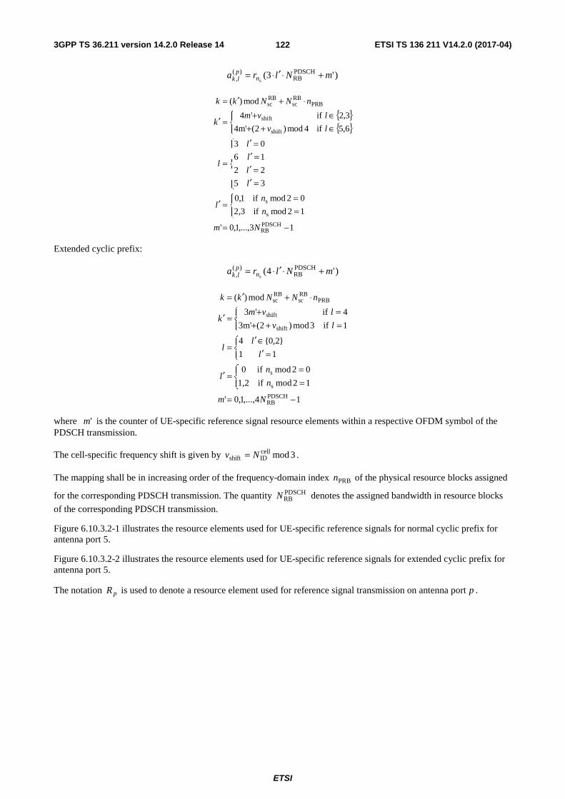
3GPP TS 36.211 version 14.2.0 Release 14 ETSI TS 136 211 V14.2.0 (2017-04)
ETSI
122
)'3( PDSCHRB
)(, s
mNlra nplk +⋅′⋅=
{ }{ }
13,...,1,0'
12mod if2,3
02mod if1,0
35
22
16
03
6,5 if4mod)2(4m'
3,2 if'4
mod)(
PDSCHRB
s
s
shift
shift
PRBRBsc
RBsc
−=⎩⎨⎧
==
=′
⎪⎪
⎩
⎪⎪
⎨
⎧
=′=′=′=′
=
⎩⎨⎧
∈++∈+
=′
⋅+′=
Nm
n
nl
l
l
l
l
l
lv
lvmk
nNNkk
Extended cyclic prefix:
)'4( PDSCHRB
)(, s
mNlra nplk +⋅′⋅=
14,...,1,0'
12mod if1,2
02mod if0
11
}2,0{4
1 if3mod)2(3m'
4 if'3
mod)(
PDSCHRB
s
s
shift
shift
PRBRBsc
RBsc
−=⎩⎨⎧
==
=′
⎩⎨⎧
=′∈′
=
⎩⎨⎧
=++=+
=′
⋅+′=
Nm
n
nl
l
ll
lv
lvmk
nNNkk
where 'm is the counter of UE-specific reference signal resource elements within a respective OFDM symbol of the PDSCH transmission.
The cell-specific frequency shift is given by 3modcellIDshift Nv = .
The mapping shall be in increasing order of the frequency-domain index BPRn of the physical resource blocks assigned
for the corresponding PDSCH transmission. The quantity PDSCHRBN denotes the assigned bandwidth in resource blocks
of the corresponding PDSCH transmission.
Figure 6.10.3.2-1 illustrates the resource elements used for UE-specific reference signals for normal cyclic prefix for antenna port 5.
Figure 6.10.3.2-2 illustrates the resource elements used for UE-specific reference signals for extended cyclic prefix for antenna port 5.
The notation pR is used to denote a resource element used for reference signal transmission on antenna port p .
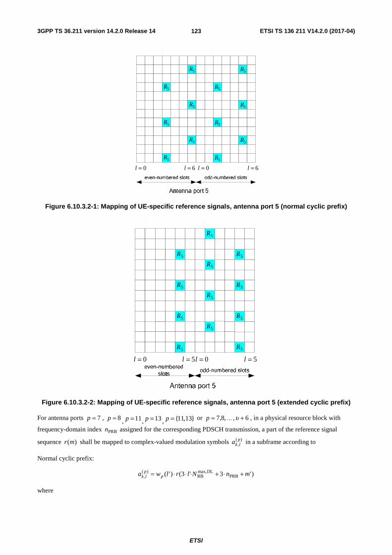
3GPP TS 36.211 version 14.2.0 Release 14 ETSI TS 136 211 V14.2.0 (2017-04)
ETSI
123
0=l
5R
5R
5R
5R
5R
5R
5R
5R
5R
5R
5R
5R
0=l 6=l6=l
Figure 6.10.3.2-1: Mapping of UE-specific reference signals, antenna port 5 (normal cyclic prefix)
0=l
5R
5R
0=l 5=l5=l
5R
5R
5R
5R
5R
5R
5R
5R
5R
5R
Figure 6.10.3.2-2: Mapping of UE-specific reference signals, antenna port 5 (extended cyclic prefix)
For antenna ports 7=p , 8=p , 11p = , 13p = , {11,13}p = or 6,,8,7 += υKp , in a physical resource block with
frequency-domain index BPRn assigned for the corresponding PDSCH transmission, a part of the reference signal
sequence )(mr shall be mapped to complex-valued modulation symbols )(,plka in a subframe according to
Normal cyclic prefix:
)'3'3()'( PRBDLmax,
RB)(
, mnNlrlwa pplk +⋅+⋅⋅⋅=
where

3GPP TS 36.211 version 14.2.0 Release 14 ETSI TS 136 211 V14.2.0 (2017-04)
ETSI
124
{ }{ }
⎣ ⎦
2,1,0'
1)-4.2 Table (see 7or 6, 2, 1,ion configurat with subframe specialin not and 12mod if3,2
1)-4.2 Table (see 7or 6, 2, 1,ion configurat with subframe specialin not and 02mod if1,0
1)-4.2 Table (see 7or 6, 2, 1,ion configurat with subframe special ain and 02mod if3,2,1,0
'
subframe special ain not if52mod'
1)-4.2 Table (see 7or 6, 2, 1,ion configurat with subframe special ain if2/'322mod'
1)-4.2 Table (see 9or 8 4, 3,ion configurat with subframe special ain if22mod'
14,12,10,90
13,11,8,71'
''5
12mod)'()3(
02mod)'()()(
s
s
s
PRBRBsc
PRB
PRB
=
⎪⎩
⎪⎨
⎧
===
=
⎪⎩
⎪⎨
⎧
+++
+=
⎩⎨⎧
∈∈
=
++=⎩⎨⎧
=+−=+
=
m
n
n
n
l
l
ll
l
l
p
pk
knNmk
nmiw
nmiwiw
p
pp
The sequence )(iwp is given by Table 6.10.3.2-1.
Table 6.10.3.2-1: The sequence )(iwp for normal cyclic prefix
Antenna port p [ ])3()2()1()0( pppp wwww
7 [ ]1111 ++++
8 [ ]1111 −+−+
9 [ ]1111 ++++
10 [ ]1111 −+−+
11 [ ]1111 −−++
12 [ ]1111 ++−−
13 [ ]1111 +−−+
14 [ ]1111 −++−
Extended cyclic prefix:
)'4'4()2mod'( PRBDLmax,
RB)(
, mnNlrlwa pplk +⋅+⋅⋅⋅=
where
{ }{ }
3,2,1,0'
subframe speciala innot and 12mod if
subframe speciala innot and 02mod if
3,2
1,01)-4.2 Table (see 6or 5 3, 2, 1, ionconfigurat withsubframe speciala in and 02mod if1,0
'
42mod
8,7 and 12mod if2
8,7 and 02mod if1'
''3
12mod)1(
02mod)()(
s
s
s
s
s
PRBRBsc
=
⎪⎩
⎪⎨
⎧
===
=
+′=⎩⎨⎧
∈=∈=
=
++=⎩⎨⎧
=′−=′
=
m
n
nn
l
ll
pn
pnk
knNmk
miw
miwiw
p
p
p
The sequence )(iwp is given by Table 6.10.3.2-2.
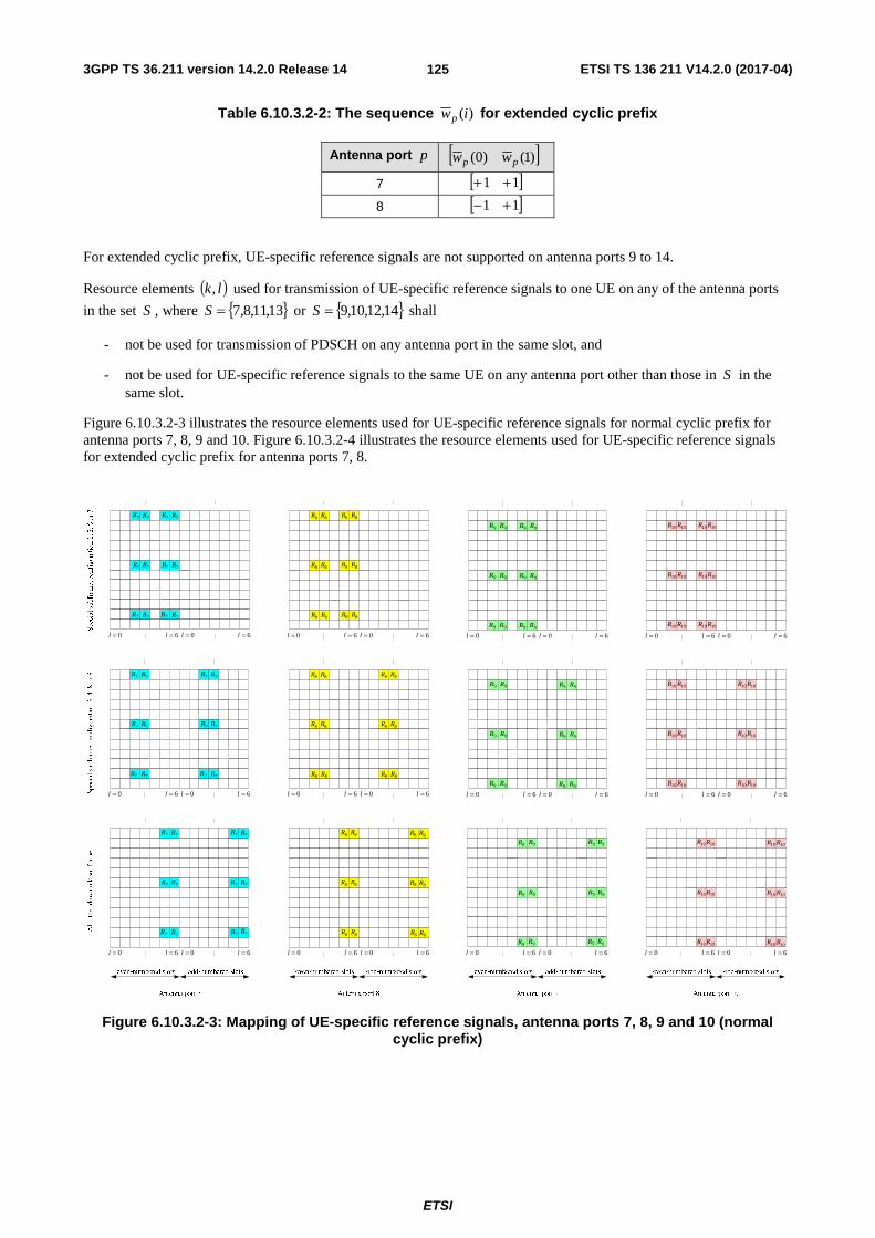
3GPP TS 36.211 version 14.2.0 Release 14 ETSI TS 136 211 V14.2.0 (2017-04)
ETSI
125
Table 6.10.3.2-2: The sequence )(iwp for extended cyclic prefix
Antenna port p [ ])1()0( pp ww
7 [ ]11 ++
8 [ ]11 +−
For extended cyclic prefix, UE-specific reference signals are not supported on antenna ports 9 to 14.
Resource elements ( )lk, used for transmission of UE-specific reference signals to one UE on any of the antenna ports
in the set S , where { }13,11,8,7=S or { }14,12,10,9=S shall
- not be used for transmission of PDSCH on any antenna port in the same slot, and
- not be used for UE-specific reference signals to the same UE on any antenna port other than those in S in the same slot.
Figure 6.10.3.2-3 illustrates the resource elements used for UE-specific reference signals for normal cyclic prefix for antenna ports 7, 8, 9 and 10. Figure 6.10.3.2-4 illustrates the resource elements used for UE-specific reference signals for extended cyclic prefix for antenna ports 7, 8.
0=l 6=l 0=l 6=lSpecial subframe, configuration 1, 2, 6 or 7
Special subframe, configuration 3, 4, 8 or 9
0=l 6=l 0=l 6=l 0=l 6=l 0=l 6=l
0=l 6=l 0=l 6=l 0=l 6=l 0=l 6=l
All other downlink subframes
0=l 6=l 0=l 6=l 0=l 6=l 0=l 6=l
7R 7R 7R 7R
7R7R7R7R
7R 7R 7R 7R 8R 8R 8R 8R
8R 8R 8R 8R
8R 8R 8R 8R
9R 9R 9R 9R
9R 9R 9R 9R
9R 9R 9R 9R
10R 10R 10R 10R
10R 10R 10R 10R
10R 10R 10R 10R
7R 7R
7R7R
7R 7R
7R 7R
7R7R
7R 7R 8R 8R
8R 8R
8R 8R
8R 8R
8R 8R
8R 8R
7R 7R
7R7R
7R 7R
7R 7R
7R7R
7R 7R 8R 8R
8R 8R
8R 8R
0=l 6=l 0=l 6=l
8R 8R
8R 8R
8R 8R
0=l 6=l 0=l 6=l 0=l 6=l 0=l 6=l
0=l 6=l 0=l 6=l 0=l 6=l 0=l 6=l
9R 9R
9R 9R
9R 9R
9R 9R
9R 9R
9R 9R
10R 10R
10R 10R
10R 10R
10R 10R
10R 10R
10R 10R
9R 9R
9R 9R
9R 9R
9R 9R
9R 9R
9R 9R
10R 10R
10R 10R
10R 10R
10R 10R
10R 10R
10R 10R
Figure 6.10.3.2-3: Mapping of UE-specific reference signals, antenna ports 7, 8, 9 and 10 (normal cyclic prefix)

3GPP TS 36.211 version 14.2.0 Release 14 ETSI TS 136 211 V14.2.0 (2017-04)
ETSI
126
Special subframe, configuration 1, 2, 3, 5
or 6
0=l 5=l 0=l 5=l 0=l 5=l 0=l 5=l
0=l 5=l 0=l 5=l 0=l
8R
5=l 0=l 5=l
All other downlink subframes
7R 7R
7R 7R
7R 7R
7R 7R
7R 7R
7R 7R
7R 7R
7R 7R
8R
8R 8R
8R 8R
8R 8R
8R 8R
8R 8R
8R 8R
8R 8R
7R 7R
7R 7R
7R 7R
7R 7R
8R 8R
8R 8R
8R 8R
8R 8R
Figure 6.10.3.2-4: Mapping of UE-specific reference signals, antenna ports 7 and 8 (extended cyclic prefix)
6.10.3A Demodulation reference signals associated with EPDCCH or MPDCCH
The demodulation reference signal associated with EPDCCH/MPDCCH
- is transmitted on the same antenna port { }110,109,108,107∈p as the associated EPDCCH/MPDCCH physical
resource;
- is present and is a valid reference for EPDCCH/MPDCCH demodulation only if the EPDCCH/MPDCCH transmission is associated with the corresponding antenna port;
- is transmitted only on the physical resource blocks upon which the corresponding EPDCCH/MPDCCH is mapped.
A demodulation reference signal associated with EPDCCH/MPDCCH is not transmitted in resource elements ( )lk, in
which one of the physical channels or physical signals other than the demodulation reference signals defined in 6.1 are transmitted using resource elements with the same index pair ( )lk, regardless of their antenna port p .
6.10.3A.1 Sequence generation
For any of the antenna ports { }110,109,108,107∈p , the reference-signal sequence )(mr is defined by
( ) ( )⎪⎩
⎪⎨⎧
−−=+⋅−+⋅−=
prefix cyclic extended11610
prefix cyclic normal11210 ,)12(21
2
1)2(21
2
1)(
DLmax,RB
DLmax,RB
N,...,,
N,...,,mmcjmcmr .
For non-BL/CE UEs, the pseudo-random sequence )(nc is defined in clause 7.2. The pseudo-random sequence
generator shall be initialised with
⎣ ⎦( ) ( ) EPDCCHSCID
16EPDCCHIDsinit 21212/ nnnc ,i +⋅+⋅+=
at the start of each subframe where 2EPDCCHSCID =n and EPDCCH
ID,in is configured by higher layers. The EPDCCH set to
which the EPDCCH associated with the demodulation reference signal belong is denoted { }1,0∈i .

3GPP TS 36.211 version 14.2.0 Release 14 ETSI TS 136 211 V14.2.0 (2017-04)
ETSI
127
For BL/CE UEs, the same scrambling sequence is applied per subframe to the demodulation reference signal associated
with MPDCCH for a given block of accN subframes. For the thj block of accN subframes, the scrambling sequence
generator shall be initialised with
( )[ ]( ) ( )( )[ ]( ) ( )⎩
⎨⎧
+⋅+⋅+++⋅+⋅++
=Common-Type2 andCommon -Type1for 212110mod
otherwise212110modMPDCCHSCID
16cellIDacc0
MPDCCHSCID
16MPDCCHIDacc0
initnNNjj
nNNjjc ,i where
( )⎣ ⎦
⎩⎨⎧
=−=
=
+=
−⎥⎦
⎥⎢⎣
⎢ −++=
Δ
Δ
Δ
10 and 2 typestructure framefor ,2
1or 1 typestructure framefor 0,
1,...,1,0
accacc
acc
acc00
0acc
MPDCCHabs0
NN
Ni
Niij
jN
iNij
and 0i is the absolute subframe number of the first downlink subframe intended for MPDCCH. The MPDCCH
transmissions span MPDCCHabsN consecutive subframes, including non-BL/CE DL subframes where the MPDCCH
transmission is postponed.
For BL/CE UEs,
- if the MPDCCH transmission is associated with P-RNTI or SC-RNTI:
- 4acc =N for frame structure type 1 and 10acc =N for frame structure type 2
- otherwise
- 1acc =N for UEs assuming CEModeA (according to the definition in Clause 12 of [4]) or configured with
CEModeA.
- 4acc =N for frame structure type 1 and 10acc =N for frame structure type 2 for UEs assuming CEModeB
(according to the definition in Clause 12 of [4]) or configured with CEModeB.
The quantities 2MPDCCHSCID =n and MPDCCH
ID,in are configured by higher layers. The MPDCCH set to which the MPDCCH
associated with the demodulation reference signal belong is denoted { }1,0∈i . For an MPDCCH associated with a 2+4
PRB set as defined in [4], 0=i is used to generate the scrambling sequence for the 6 PRBs as well as for the 2 PRBs and 4 PRBs.
6.10.3A.2 Mapping to resource elements
For the antenna port { }110,109,108,107∈p in a physical resource block PRBn assigned for the associated
EPDCCH/MPDCCH, a part of the reference signal sequence )(mr shall be mapped to complex-valued modulation
symbols )(,plka in a subframe according to
Normal cyclic prefix:
)'3'3()'( PRBDLmax,
RB)(
, mnNlrlwa pplk +⋅+⋅⋅⋅=
where
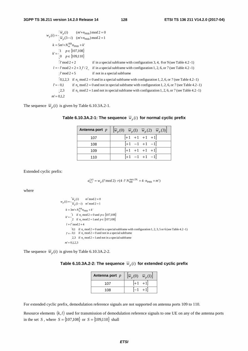
3GPP TS 36.211 version 14.2.0 Release 14 ETSI TS 136 211 V14.2.0 (2017-04)
ETSI
128
{ }{ }
⎣ ⎦
2,1,0'
1)-4.2 Table (see 7or 6, 2, 1,ion configurat with subframe specialin not and 12mod if3,2
1)-4.2 Table (see 7or 6, 2, 1,ion configurat with subframe specialin not and 02mod if1,0
1)-4.2 Table (see 7or 6, 2, 1,ion configurat with subframe special ain and 02mod if3,2,1,0
'
subframe special ain not if52mod'
1)-4.2 Table (see 7or 6, 2, 1,ion configurat with subframe special ain if2/'322mod'
1)-4.2 Table (see 9or 8 4, 3,ion configurat with subframe special ain if22mod'
110,1090
108,1071'
''5
12mod)'()3(
02mod)'()()(
s
s
s
PRBRBsc
PRB
PRB
=
⎪⎩
⎪⎨
⎧
===
=
⎪⎩
⎪⎨
⎧
+++
+=
⎩⎨⎧
∈∈
=
++=⎩⎨⎧
=+−=+
=
m
n
n
n
l
l
ll
l
l
p
pk
knNmk
nmiw
nmiwiw
p
pp
The sequence )(iwp is given by Table 6.10.3A.2-1.
Table 6.10.3A.2-1: The sequence )(iwp for normal cyclic prefix
Antenna port p [ ])3()2()1()0( pppp wwww
107 [ ]1111 ++++
108 [ ]1111 −+−+
109 [ ]1111 ++++
110 [ ]1111 −+−+
Extended cyclic prefix:
)'4'4()2mod'( PRBDLmax,
RB)(
, mnNlrlwa pplk +⋅+⋅⋅⋅=
where
{ }{ }
3,2,1,0'
subframe special ain not and 12mod if
subframe special ain not and 02mod if
3,2
1,01)-4.2 Table (see 6or 5 3, 2, 1,ion configurat with subframe special ain and 02mod if1,0
'
42mod
108,107 and 12mod if2
108,107 and 02mod if1'
''3
12mod)1(
02mod)()(
s
s
s
s
s
PRBRBsc
=
⎪⎩
⎪⎨
⎧
===
=
+′=⎩⎨⎧
∈=∈=
=
++=⎩⎨⎧
=′−=′
=
m
n
nn
l
ll
pn
pnk
knNmk
miw
miwiw
p
pp
The sequence )(iwp is given by Table 6.10.3A.2-2.
Table 6.10.3A.2-2: The sequence )(iwp for extended cyclic prefix
Antenna port p [ ])1()0( pp ww
107 [ ]11 ++
108 [ ]11 +−
For extended cyclic prefix, demodulation reference signals are not supported on antenna ports 109 to 110.
Resource elements ( )lk, used for transmission of demodulation reference signals to one UE on any of the antenna ports
in the set S , where { }108,107=S or { }110,109=S shall

3GPP TS 36.211 version 14.2.0 Release 14 ETSI TS 136 211 V14.2.0 (2017-04)
ETSI
129
- not be used for transmission of EPDCCH/MPDCCH on any antenna port in the same slot, and
- not be used for demodulation reference signals to the same UE on any antenna port other than those in S in the same slot.
Replacing antenna port numbers 7 – 10 by 107 – 110 in Figure 6.10.3.2-3 provides an illustration of the resource elements used for demodulation reference signals associated with EPDCCH/MPDCCH for normal cyclic prefix. Replacing antenna port numbers 7 – 8 by 107 – 108 in Figure 6.10.3.2-4 provides an illustration of the resource elements used for demodulation reference signals associated with EPDCCH/MPDCCH for extended cyclic prefix.
For frame structure type 3, for EPDCCH in a subframe with the same duration as the DwPTS duration of a special subframe configuration, the mapping of the demodulation reference signals to the resource elements is the same as that for the corresponding special subframe configuration.
6.10.4 Positioning reference signals
Positioning reference signals shall only be transmitted in resource blocks in downlink subframes configured for positioning reference signal transmission. If both normal and MBSFN subframes are configured as positioning subframes within a cell, the OFDM symbols in a MBSFN subframe configured for positioning reference signal transmission shall use the same cyclic prefix as used for subframe #0. If only MBSFN subframes are configured as positioning subframes within a cell, the OFDM symbols configured for positioning reference signals in the MBSFN region of these subframes shall use extended cyclic prefix length. In a subframe configured for positioning reference signal transmission, the starting positions of the OFDM symbols configured for positioning reference signal transmission shall be identical to those in a subframe in which all OFDM symbols have the same cyclic prefix length as the OFDM symbols configured for positioning reference signal transmission.
Positioning reference signals are transmitted on antenna port 6.
The positioning reference signals shall not be mapped to resource elements ( )lk, allocated to the core part of the
PBCH, PSS or SSS regardless of their antenna port p .
Positioning reference signals are defined for kHz 15=Δf only.
6.10.4.1 Sequence generation
The reference-signal sequence )(s, mr nl is defined by
( ) ( ) 12,...,1,0 ,)12(212
1)2(21
2
1)( DLmax,
RB, s−=+⋅−+⋅−= Nmmcjmcmr nl
where sn is the slot number within a radio frame, l is the OFDM symbol number within the slot. The pseudo-random
sequence )(ic is defined in clause 7.2. The pseudo-random sequence generator shall be initialised with
⎣ ⎦ ( )( ) ( )( ) ( ) CPPRSID
PRSIDs
10PRSID
28init 512mod21512mod211725122 NNNlnNc +⋅++⋅⋅+++⋅⋅+⋅= at the start of each
OFDM symbol where { }4095,...,1,0PRSID ∈N equals cell
IDN unless configured by higher layers and where
⎩⎨⎧
=CP extendedfor 0
CP normalfor 1CPN
6.10.4.2 Mapping to resource elements
If PRS frequency hopping is not configured by higher layers, the reference signal sequence )(s, mr nl shall be mapped to
complex-valued modulation symbols )(,plka used as reference signal for antenna port 6=p in slot sn according to
)'(s,
)(, mra nlplk =
where
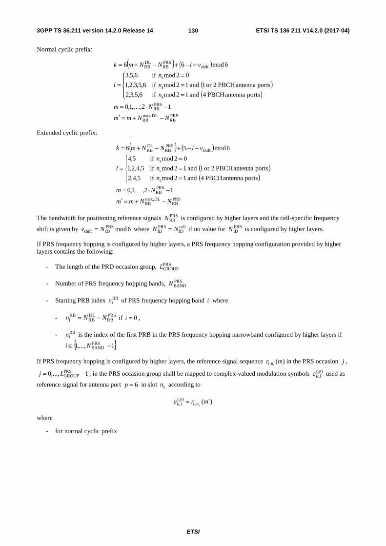
3GPP TS 36.211 version 14.2.0 Release 14 ETSI TS 136 211 V14.2.0 (2017-04)
ETSI
130
Normal cyclic prefix:
( ) ( )
( )( )
PRSRB
DLmax,RB
PRSRB
s
s
s
shiftPRSRB
DLRB
12,,1,0
portsantennaPBCH4and12modif6,5,3,2
portsantennaPBCH2or1and12modif6,5,3,2,1
02modif6,5,3
6mod66
NNmm
Nm
n
n
n
l
vlNNmk
−+=′
−⋅=
⎪⎩
⎪⎨
⎧
===
=
+−+−+=
K
Extended cyclic prefix:
( ) ( )
( )( )
PRSRB
DLmax,RB
PRSRB
s
s
s
shiftPRSRB
DLRB
12,,1,0
portsantennaPBCH4and12modif5,4,2
portsantennaPBCH2or1and12modif5,4,2,1
02modif5,4
6mod56
NNmm
Nm
n
n
n
l
vlNNmk
−+=′
−⋅=
⎪⎩
⎪⎨
⎧
===
=
+−+−+=
K
The bandwidth for positioning reference signals PRSRBN is configured by higher layers and the cell-specific frequency
shift is given by 6modPRSIDshift Nv = where cell
IDPRSID NN = if no value for PRS
IDN is configured by higher layers.
If PRS frequency hopping is configured by higher layers, a PRS frequency hopping configuration provided by higher layers contains the following:
- The length of the PRD occasion group, PRSGROUPL
- Number of PRS frequency hopping bands, PRS BANDN
- Starting PRB index RBin of PRS frequency hopping band i where
- PRSRB
DLRB
RBi NNn −= if 0=i ,
- RBin is the index of the first PRB in the PRS frequency hopping narrowband configured by higher layers if
{ }1,...,1 PRS BAND −∈ Ni
If PRS frequency hopping is configured by higher layers, the reference signal sequence )(s, mr nl in the PRS occasion j ,
1,...,0 PRSGROUP −= Lj , in the PRS occasion group shall be mapped to complex-valued modulation symbols )(
,plka used as
reference signal for antenna port 6=p in slot sn according to
)'(s,
)(, mra nlplk =
where
- for normal cyclic prefix

3GPP TS 36.211 version 14.2.0 Release 14 ETSI TS 136 211 V14.2.0 (2017-04)
ETSI
131
( ) ( )
( )( )
DLRB
DLmax,RB
RBi
PRSRB
s
s
s
shiftRBi
PRSBAND
12,,1,0
portsantennaPBCH4and12modif6,5,3,2
portsantennaPBCH2or1and12modif6,5,3,2,1
02modif6,5,3
6mod66
mod
NNnmm
Nm
n
n
n
l
vlnmk
Nji
−++=′
−⋅=
⎪⎩
⎪⎨
⎧
===
=
+−++=
=
K
- for extended cyclic prefix
( ) ( )
( )( )
DLRB
DLmax,RB
RBi
PRSRB
s
s
s
shiftRBi
PRSBAND
12,,1,0
portsantennaPBCH4and12modif5,4,2
portsantennaPBCH2or1and12modif5,4,2,1
02modif5,4
6mod56
mod
NNnmm
Nm
n
n
n
l
vlnmk
Nji
−++=′
−⋅=
⎪⎩
⎪⎨
⎧
===
=
+−++=
=
K
0=l 6=l 0=l 6=l
Four PBCH antenna ports
6R
6R
6R
6R
6R
6R
6R
6R
6R
6R
6R
6R
6R
6R
0=l 6=l 0=l 6=l
One and two PBCH antenna
ports
6R
6R
6R
6R
6R
6R
6R
6R
6R
6R
6R
6R
6R
6R
6R
6R
Figure 6.10.4.2-1: Mapping of positioning reference signals (normal cyclic prefix)

3GPP TS 36.211 version 14.2.0 Release 14 ETSI TS 136 211 V14.2.0 (2017-04)
ETSI
132
0=l 5=l 0=l 5=l
6R
6R
6R
6R
6R
6R
6R
6R
6R
6R
0=l 5=l 0=l 5=l
6R
6R
6R
6R
6R
6R
6R
6R
6R
6R
6R
6R
Figure 6.10.4.2-2: Mapping of positioning reference signals (extended cyclic prefix)
6.10.4.3 Positioning reference signal subframe configuration
The subframe configuration period PRST and the subframe offset PRSΔ for the transmission of positioning reference
signals are listed in Table 6.10.4.3-1. The PRS configuration index PRSI is configured by higher layers. Positioning
reference signals are transmitted only in configured DL subframes. Positioning reference signals shall not be transmitted in DwPTS. Positioning reference signals shall be transmitted in PRSN consecutive downlink subframes,
where PRSN is configured by higher layers.
The positioning reference signal instances, for the first subframe of the PRSN downlink subframes, shall satisfy
⎣ ⎦( ) 0mod2/10 PRSPRSsf =Δ−+× Tnn .
Table 6.10.4.3-1: Positioning reference signal subframe configuration
PRS configuration Index PRSI PRS periodicity PRST (subframes)
PRS subframe offset PRSΔ (subframes)
0 – 159 160 PRSI
160 – 479 320 160PRS −I
480 – 1119 640 480PRS −I
1120 – 2399 1280 1120PRS −I
2400 – 2404 5 2400PRS −I
2405 – 2414 10 2405PRS −I
2415 – 2434 20 2415PRS −I
2435 – 2474 40 2435PRS −I
2475 – 2554 80 2475PRS −I
2555-4095 Reserved
6.10.5 CSI reference signals
CSI reference signals are transmitted on 1, 2, 4, 8, 12, 16, 20, 24, 28, or 32 antenna ports using 15=p , 16,15=p ,
18,...,15=p , 22,...,15=p , 26,...,15=p , 30,...,15=p , 34,...,15=p , 38,...,15=p , 42,...,15=p and 46,...,15=p ,
respectively.
For CSI reference signals using more than eight antenna ports, 1CSIres >N CSI-RS configurations in the same subframe,
numbered from 0 to 1CSIres −N , where value 0 corresponds to the configured resourceConfig-r11 or resourceConfig-r10

3GPP TS 36.211 version 14.2.0 Release 14 ETSI TS 136 211 V14.2.0 (2017-04)
ETSI
133
and value k (k>0) corresponds to the configured k-th entry of nzp-resourceConfigList-r13, are aggregated to obtain CSIports
CSIres NN antenna ports in total. Each CSI-RS configuration in such an aggregation corresponds to { }8,4CSI
ports ∈N
antenna ports and one of the configurations in Table 6.10.5.3-1 or 6.10.5.2-1 for normal cyclic prefix, and one of the configurations in Table 6.10.5.3-1 or 6.10.5.2-2 for extended cyclic prefix. The supported configurations of aggregated CSI-RS configurations are shown in Table 6.10.5-1. If the higher layer parameter NZP-TransmissionComb is not
configured, CSIresN unique CSI-RS configurations from Table 6.10.5.2-1 for normal cyclic prefix and from Table
6.10.5.2-2 for extended cyclic prefix are aggregated to form 12, 16, 20, 24, 28, or 32 antenna ports.
For CSI reference signals using more than sixteen antenna ports, when higher layer parameter NZP-TransmissionComb is configured, the number of unique CSI-RS configurations from Table 6.10.5.2-1 for normal cyclic prefix and from Table 6.10.5.2-2 for extended cyclic prefix that are aggregated to form 20, 24, 28, or 32 antenna ports can be less than
or equal to CSIresN . The number of antenna ports within each such unique CSI-RS resrouce configuration is an integer
multiple of CSIportsN .
CSI reference signals are defined for kHz 15=Δf only.
Table 6.10.5-1: Aggregation of CSI-RS configurations.
Total number of antenna ports
CSIports
CSIres NN
Number of antenna ports per CSI-RS configuration
CSIportsN
Number of CSI-RS configurations
CSIresN
12 4 3 16 8 2 20 4 5 24 8 3 28 4 7 32 8 4
6.10.5.1 Sequence generation
The reference-signal sequence )(s, mr nl is defined by
( ) ( ) 1,...,1,0 ,)12(212
1)2(21
2
1)( DLmax,
RB, s−=+⋅−+⋅−= Nmmcjmcmr nl
where sn is the slot number within a radio frame and l is the OFDM symbol number within the slot. The pseudo-
random sequence )(ic is defined in clause 7.2. The pseudo-random sequence generator shall be initialised with
( )( ) ( ) CPCSIID
CSIIDs
10init 2121172 NNNlnc +⋅++⋅⋅+++′⋅⋅= at the start of each OFDM symbol where
⎣ ⎦
⎩⎨⎧
=
⎩⎨⎧ +
=′
CP extendedfor 0
CP normalfor 1
otherwise
DRS a ofpart is RS-CSI when the3 typestructure framefor 2mod1010
CP
s
sss
N
n
nnn
The quantity CSIIDN equals cell
IDN unless configured by higher layers.
6.10.5.2 Mapping to resource elements
In subframes configured for CSI reference signal transmission, the reference signal sequence )(s, mr nl shall be mapped
to complex-valued modulation symbols )(,plka used as reference symbols on antenna port p . The mapping depends on
the higher-layer parameter CDMType.
For the case of CDMType is not configured or is configured to CDM2:

3GPP TS 36.211 version 14.2.0 Release 14 ETSI TS 136 211 V14.2.0 (2017-04)
ETSI
134
)'(s,"
)(, mrwa nllplk ⋅=′
where
{ }{ }{ }{ }{ }{ }{ }{ }
{ }( ) { }
⎥⎥⎦
⎥
⎢⎢⎣
⎢ −+=
=⎩⎨⎧
∈′−∈′
=
⎪⎩
⎪⎨
⎧
+=
⎪⎪⎪⎪⎪
⎩
⎪⎪⎪⎪⎪
⎨
⎧
∈′−∈′−∈′−∈′−∈′−∈′−∈′−∈′−
++=
′′
2'
1,0"
22,20,18,161
21,19,17,151
prefix cyclic extended 27,-0 ionsconfigurat signal reference CSI"
prefix cyclic normal 31,-20 ionsconfigurat signal reference CSI"2
prefix cyclic normal 19,-0 ionsconfigurat signal reference CSI"
'
prefix cyclic extended,22,21for 9
prefix cyclic extended,20,19for 6
prefix cyclic extended,18,17for 3
prefix cyclic extended,16,15for 0
prefix cyclic normal,22,21for 7
prefix cyclic normal,20,19for 1
prefix cyclic normal,18,17for 6
prefix cyclic normal,16,15for 0
12'
DLRB
DLmax,RB
"
NNmm
l
p
pw
l
l
l
ll
p
p
p
p
p
p
p
p
mkk
ll
For the case of CDMType equal to CDM4:
( ) )'(s,'
)'(, mriwa nlpplk ⋅=
where
{ }{ }{ }
⎥⎥⎦
⎥
⎢⎢⎣
⎢ −+=
+===
⎩⎨⎧
+=
⎪⎩
⎪⎨
⎧
=∈′=∈′+=∈′
−+=
2'
''''2
1,0''
1,0"
prefix cyclic normal 31,-20 ionsconfigurat signal reference CSI''2
prefix cyclic normal 19,-0 ionsconfigurat signal reference CSI'''
4 prefix, cyclic normal,18,17,16,15for ''6
8 prefix, cyclic normal,22,21,18,17for 6''
8 prefix, cyclic normal,20,19,16,15for ''
12'
DLRB
DLmax,RB
CSIports
CSIports
CSIports
NNmm
lki
k
l
l
lll
Npk
Npk
Npk
mkk
and where )(' iwp is given by Table 6.10.5.2-0.

3GPP TS 36.211 version 14.2.0 Release 14 ETSI TS 136 211 V14.2.0 (2017-04)
ETSI
135
Table 6.10.5.2-0: The sequence )(' iwp for CDM4.
p′ [ ])3()2()1()0( '''' pppp wwww
4CSIports =N
8CSI
ports =N
15 15,17 [ ]1111
16 16,18 [ ]1111 −−
17 19,21 [ ]1111 −−
18 20,22 [ ]1111 −−
If neither of the higher-layer parameters NZP-FrequencyDensity and NZP-TransmissionComb are configured,
1,...,1,0 DLRB −= Nm .
If the UE is configured with one or more of the parameters NZP-FrequencyDensity and NZP-TransmissionComb,
- if either NZP-FrequencyDensity equals 1, 1,...,1,0 DLRB −= Nm
- if NZP-FrequencyDensity equals 1/2 and NZP-TransmissionComb equals 0,
( )( )2mod11,...,2,0 DLRB
DLRB −−−= NNm
- if NZP-FrequencyDensity equals 1/2 and NZP-TransmissionComb equals 1,
( )( )2mod11,...,3,1 DLRB
DLRB −−−= NNm
- if NZP-FrequencyDensity equals 1/3 and NZP-TransmissionComb equals 0,
( )( )3mod11,...,3,0 DLRB
DLRB −−−= NNm
- if NZP-FrequencyDensity equals 1/3 and NZP-TransmissionComb equals 1,
( )( )3mod21,...,4,1 DLRB
DLRB −−−= NNm
- if NZP-FrequencyDensity equals 1/3 and NZP-TransmissionComb equals 2,
( )( )3mod31,...,5,2 DLRB
DLRB −−−= NNm
The quantity )','( lk and the necessary conditions on sn are given by Tables 6.10.5.2-1 and 6.10.5.2-2 for normal and
extended cyclic prefix, respectively.
The relation between the antenna port number p and the quantity p′ depends on the number of CSI-RS antenna ports:
- for CSI reference signals using up to eight antenna ports, pp ′=
- for CSI reference signals using more than eight antenna ports when the higher-layer parameter CDMType equals CDM2
{ }( ) { }⎪
⎪
⎩
⎪⎪
⎨
⎧
−++∈−++
−+∈+=
115,...,215'for 12
´
1215,...,15'for 2
'
CSIports
CSIports
CSIres
CSIports
CSIports
CSIports
NNpNiN
p
NpiN
pp
where { }1,...,1,0 CSIres −∈ Ni is the CSI-RS resource number.
- for CSI reference signals using more than eight antenna ports when the higher-layer parameter CDMType equals
CDM4, antenna port number 'CSIports piNp += where { }115,..,16,15' CSI
ports −+∈ Np for CSI-RS resource number
{ }1,...,1,0 CSIres −∈ Ni .
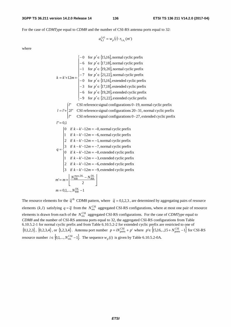
3GPP TS 36.211 version 14.2.0 Release 14 ETSI TS 136 211 V14.2.0 (2017-04)
ETSI
136
For the case of CDMType equal to CDM8 and the number of CSI-RS antenna ports equal to 32:
( ) )'(s,
)(, mriwa nlpplk ⋅=
where
{ }{ }{ }{ }{ }{ }{ }{ }
1,...,1,0
2'
prefix cyclic extended,912' if3
prefix cyclic extended,612' if2
prefix cyclic extended,312' if1
prefix cyclic extended,012' if0
prefix cyclic normal,712' if3
prefix cyclic normal,112' if2
prefix cyclic normal,612' if1
prefix cyclic normal,012' if0
1,0"
prefix cyclic extended 27,-0 ionsconfigurat signal reference CSI"
prefix cyclic normal 31,-20 ionsconfigurat signal reference CSI"2
prefix cyclic normal 19,-0 ionsconfigurat signal reference CSI"
'
prefix cyclic extended,22,21for 9
prefix cyclic extended,20,19for 6
prefix cyclic extended,18,17for 3
prefix cyclic extended,16,15for 0
prefix cyclic normal,22,21for 7
prefix cyclic normal,20,19for 1
prefix cyclic normal,18,17for 6
prefix cyclic normal,16,15for 0
12'
DLRB
DLRB
DLmax,RB
−=
⎥⎥⎦
⎥
⎢⎢⎣
⎢ −+=
⎪⎪⎪⎪⎪
⎩
⎪⎪⎪⎪⎪
⎨
⎧
−=−−−=−−−=−−−=−−−=−−−=−−−=−−−=−−
=
=
⎪⎩
⎪⎨
⎧
+=
⎪⎪⎪⎪⎪
⎩
⎪⎪⎪⎪⎪
⎨
⎧
∈′−∈′−∈′−∈′−∈′−∈′−∈′−∈′−
++=
Nm
NNmm
mkk
mkk
mkk
mkk
mkk
mkk
mkk
mkk
q
l
l
l
l
ll
p
p
p
p
p
p
p
p
mkk
The resource elements for the thq CDM8 pattern, where 3,2,1,0=q , are determined by aggregating pairs of resource
elements ),( lk satisfying qq = from the CSIresN aggregated CSI-RS configurations, where at most one pair of resource
elements is drawn from each of the CSIresN aggregated CSI-RS configurations. For the case of CDMType equal to
CDM8 and the number of CSI-RS antenna ports equal to 32, the aggregated CSI-RS configurations from Table 6.10.5.2-1 for normal cyclic prefix and from Table 6.10.5.2-2 for extended cyclic prefix are restricted to one of
{ }3,2,1,0 , { }4,3,2,0 , or { }4,3,2,1 . Antenna port number 'CSIports piNp += where { }115,..,16,15' CSI
ports −+∈ Np for CSI-RS
resource number { }1,...,1,0 CSIres −∈ Ni . The sequence )(iwp is given by Table 6.10.5.2-0A.

3GPP TS 36.211 version 14.2.0 Release 14 ETSI TS 136 211 V14.2.0 (2017-04)
ETSI
137
Table 6.10.5.2-0A: The sequence )(iwp for CDM8 with 32 CSI-RS antenna ports.
p ])7()6()5()4()3()2()1()0([ pppppppp wwwwwwww
15, 17, 19, 21 [ ]11111111
16, 18, 20, 22 [ ]11111111 −−−−
23, 25, 27, 29 [ ]11111111 −−−−
24, 26, 28, 30 [ ]11111111 −−−−
31, 33, 35, 37 [ ]11111111 −−−−
32, 34, 36, 38 [ ]11111111 −−−−
39, 41, 43, 45 [ ]11111111 −−−−
40, 42, 44, 46 [ ]11111111 −−−−
For the case of CDMType equal to CDM8 and the number of CSI-RS antenna ports equal to 24:
( ) )'(s,
)(, mriwa nlpplk ⋅=
where
{ }{ }
1,...,1,0
2'
prefix cyclic normal,6''12' if1
prefix, cyclic normal,0''12' if0
1,0''
1,0"
prefix cyclic normal 31,-20 ionsconfigurat signal reference CSI''2
prefix cyclic normal 19,-0 ionsconfigurat signal reference CSI'''
8 prefix, cyclic normal,22,21,18,17for 6''
8 prefix, cyclic normal,20,19,16,15for ''12'
DLRB
DLRB
DLmax,RB
CSIports
CSIports
−=
⎥⎥⎦
⎥
⎢⎢⎣
⎢ −+=
⎩⎨⎧
−=+−−=+−−
=
==
⎩⎨⎧
+=
⎪⎩
⎪⎨⎧
=∈′+=∈′
−+=
Nm
NNmm
kmkk
kmkkq
k
l
l
lll
Npk
Npkmkk
For the case of CDMType equal to CDM8 and the number of CSI-RS antenna ports equal to 24, the aggregated CSI-RS configurations from Table 6.10.5.2-1 for normal cyclic prefix are restricted to { }3,2,1 in that order. Resource elements
for CDM8 patterns are determined as follows:
- Aggregating resource element quadruplet ),( lk satisfying 0=q from CSI-RS configuration 1 with resource
element quadruplet ),( lk satisfying 0=q from CSI-RS configuration 2
- Aggregating resource element quadruplet ),( lk satisfying 0=q from CSI-RS configuration 3 with resource
element quadruplet ),( lk satisfying 1=q from CSI-RS configuration 1
- Aggregating resource element quadruplet ),( lk satisfying 1=q from CSI-RS configuration 2 with resource
element quadruplet ),( lk satisfying 1=q from CSI-RS configuration 3
Antenna port number 'CSIports piNp += where { }115,..,16,15' CSI
ports −+∈ Np for CSI-RS resource number
{ }1,...,1,0 CSIres −∈ Ni . The sequence )(iwp is given by Table 6.10.5.2-0B.
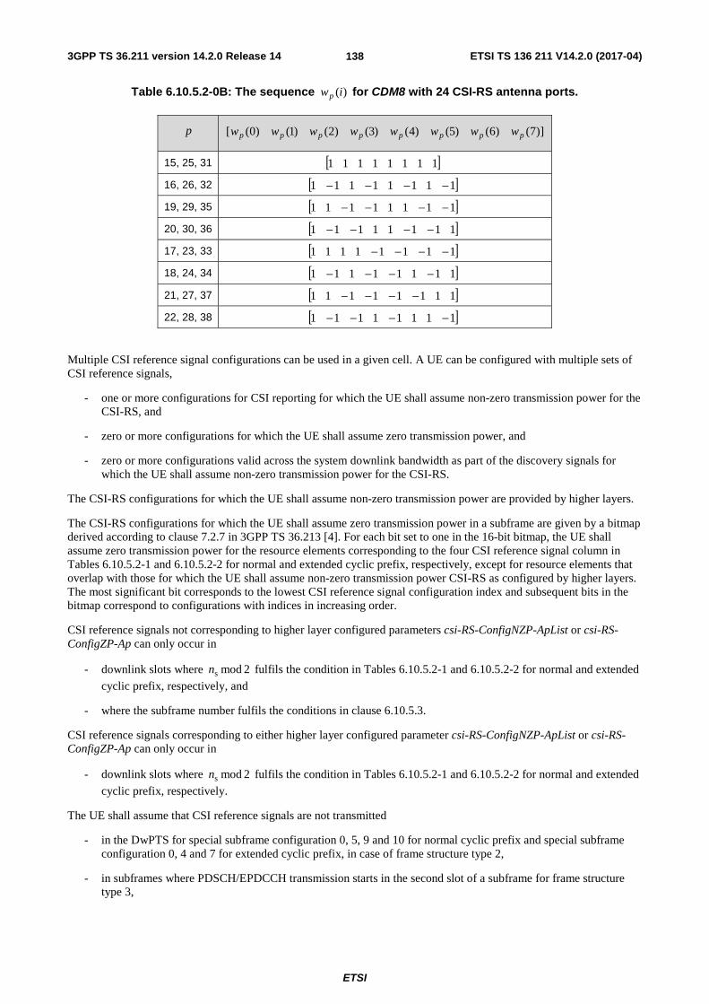
3GPP TS 36.211 version 14.2.0 Release 14 ETSI TS 136 211 V14.2.0 (2017-04)
ETSI
138
Table 6.10.5.2-0B: The sequence )(iwp for CDM8 with 24 CSI-RS antenna ports.
p ])7()6()5()4()3()2()1()0([ pppppppp wwwwwwww
15, 25, 31 [ ]11111111
16, 26, 32 [ ]11111111 −−−−
19, 29, 35 [ ]11111111 −−−−
20, 30, 36 [ ]11111111 −−−−
17, 23, 33 [ ]11111111 −−−−
18, 24, 34 [ ]11111111 −−−−
21, 27, 37 [ ]11111111 −−−−
22, 28, 38 [ ]11111111 −−−−
Multiple CSI reference signal configurations can be used in a given cell. A UE can be configured with multiple sets of CSI reference signals,
- one or more configurations for CSI reporting for which the UE shall assume non-zero transmission power for the CSI-RS, and
- zero or more configurations for which the UE shall assume zero transmission power, and
- zero or more configurations valid across the system downlink bandwidth as part of the discovery signals for which the UE shall assume non-zero transmission power for the CSI-RS.
The CSI-RS configurations for which the UE shall assume non-zero transmission power are provided by higher layers.
The CSI-RS configurations for which the UE shall assume zero transmission power in a subframe are given by a bitmap derived according to clause 7.2.7 in 3GPP TS 36.213 [4]. For each bit set to one in the 16-bit bitmap, the UE shall assume zero transmission power for the resource elements corresponding to the four CSI reference signal column in Tables 6.10.5.2-1 and 6.10.5.2-2 for normal and extended cyclic prefix, respectively, except for resource elements that overlap with those for which the UE shall assume non-zero transmission power CSI-RS as configured by higher layers. The most significant bit corresponds to the lowest CSI reference signal configuration index and subsequent bits in the bitmap correspond to configurations with indices in increasing order.
CSI reference signals not corresponding to higher layer configured parameters csi-RS-ConfigNZP-ApList or csi-RS-ConfigZP-Ap can only occur in
- downlink slots where 2modsn fulfils the condition in Tables 6.10.5.2-1 and 6.10.5.2-2 for normal and extended
cyclic prefix, respectively, and
- where the subframe number fulfils the conditions in clause 6.10.5.3.
CSI reference signals corresponding to either higher layer configured parameter csi-RS-ConfigNZP-ApList or csi-RS-ConfigZP-Ap can only occur in
- downlink slots where 2modsn fulfils the condition in Tables 6.10.5.2-1 and 6.10.5.2-2 for normal and extended
cyclic prefix, respectively.
The UE shall assume that CSI reference signals are not transmitted
- in the DwPTS for special subframe configuration 0, 5, 9 and 10 for normal cyclic prefix and special subframe configuration 0, 4 and 7 for extended cyclic prefix, in case of frame structure type 2,
- in subframes where PDSCH/EPDCCH transmission starts in the second slot of a subframe for frame structure type 3,
3GPP TS 36.211 version 14.2.0 Release 14 ETSI TS 136 211 V14.2.0 (2017-04)
ETSI
139
- in subframes where PDSCH/EPDCCH transmission ends prior to the end of a subframe for frame structure type 3,
- in an empty subframe where there is no PDSCH or discovery signal transmission for frame structure type 3,
- in subframes where transmission of a CSI-RS would collide with SystemInformationBlockType1 messages,
- in the primary cell in subframes configured for transmission of paging messages in the primary cell for any UE with the cell-specific paging configuration.
For special subframe configuration {1, 2, 6, or 7}, a UE does not expect to be configured with one of CSI-RS configurations {1, 2, 3, 4, 6, 7, 8, 9, 12, 13, 14, 15, 16, 17} in DwPTS for normal CP.
The UE shall assume that none of the CSI reference signals corresponding to a CSI reference signal configuration are transmitted in subframes where transmission of any of those CSI reference signals would collide with transmission of synchronization signals or the core part of PBCH.
Resource elements ( )lk, used for transmission of CSI reference signals on any of the antenna ports in the set S , where
{ }15=S , { }16,15=S , { }18,17=S , { }20,19=S , { }22,21=S , {23,24}S = , {25,26}S = , {27,28}S = , {29,30}S = ,
}32,31{=S , }34,33{=S , }36,35{=S , }38,37{=S , }40,39{=S , }42,41{=S , }44,43{=S or }46,45{=S shall not
be used for transmission of PDSCH on any antenna port in the same slot if higher layer parameter CDMType is not configured, or is configured to CDM2.
Resource elements ( )lk, used for transmission of CSI reference signals on any of the antenna ports in the set S , where
- { }18,17,16,15=S , { }22,21,20,19=S or { }26,25,24,23=S for CSI reference signals on 12 ports, or
- { }20,19,16,15=S , { }22,21,18,17=S , { }28,27,24,23=S or { }30,29,26,25=S for CSI reference signals on 16
ports, or
- { }18,17,16,15=S , { }22,21,20,19=S , { }26,25,24,23=S , { }30,29,28,27=S or { }34,33,32,31=S for CSI
reference signals on 20 ports, or
- { }20,19,16,15=S , { }22,21,18,17=S , { }28,27,24,23=S , { }30,29,26,25=S , { }36,35,32,31=S or
{ }38,37,34,33=S for CSI reference signals on 24 ports, or
- { }18,17,16,15=S , { }22,21,20,19=S , { }26,25,24,23=S , { }30,29,28,27=S , { }34,33,32,31=S , { }38,37,36,35=S
or { }42,41,40,39=S for CSI reference signals on 28 ports, or
- { }20,19,16,15=S , { }22,21,18,17=S , { }28,27,24,23=S , { }30,29,26,25=S , { }36,35,32,31=S ,
{ }38,37,34,33=S , { }44,43,40,39=S or { }46,45,42,41=S for CSI reference signals on 32 ports
shall not be used for transmission of PDSCH on any antenna port in the same slot if higher layer parameter CDMType is configured to CDM4.
Resource elements ( )lk, used for transmission of CSI reference signals on any of the antenna ports in the set S , where
- { }28,27,24,23,20,19,16,15=S , { }36,35,32,31,22,21,18,17=S or { }38,37,34,33,30,29,26,25=S for CSI reference
signals on 24 ports, or
- { }40,39,32,31,24,23,16,15=S , { }42,41,34,33,26,25,18,17=S , { }44,43,36,35,28,27,20,19=S or
{ }46,45,38,37,30,29,22,21=S for CSI reference signals on 32 ports
shall not be used for transmission of PDSCH on any antenna port in the same slot if higher layer parameter CDMType is configured to CDM8.
The mapping for CSI reference signal configuration 0 is illustrated in Figures 6.10.5.2-1 and 6.10.5.2-2.

3GPP TS 36.211 version 14.2.0 Release 14 ETSI TS 136 211 V14.2.0 (2017-04)
ETSI
140
Table 6.10.5.2-1: Mapping from CSI reference signal configuration to )','( lk for normal cyclic prefix
CSI-RS config.
Number of CSI reference signals configured 1 or 2 4 8
Normal subframe
Special subframe
Normal subframe
Special subframe
Normal subframe
Special subframe
( )',' lk sn′ ( )',' lk sn′
( )',' lk sn′ ( )',' lk sn′
( )',' lk sn′ ( )',' lk sn′
0 (9,5) 0 (9,5) 0 (9,5) 0 (9,5) 0 (9,5) 0 (9,5) 0 1 (11,2) 1 (11,5) 0 (11,2) 1 (11,5) 0 (11,2) 1 (11,5) 0 2 (9,2) 1 (9,2) 1 (9,2) 1 (9,2) 1 (9,2) 1 (9,2) 1 3 (7,2) 1 (7,5) 0 (7,2) 1 (7,5) 0 (7,2) 1 (7,5) 0 4 (9,5) 1 (9,5) 1 (9,5) 1 5 (8,5) 0 (8,5) 0 (8,5) 0 (8,5) 0 6 (10,2) 1 (10,5) 0 (10,2) 1 (10,5) 0 7 (8,2) 1 (8,2) 1 (8,2) 1 (8,2) 1 8 (6,2) 1 (6,5) 0 (6,2) 1 (6,5) 0 9 (8,5) 1 (8,5) 1 10 (3,5) 0 (3,5) 0 11 (2,5) 0 (2,5) 0 12 (5,2) 1 (5,5) 0 13 (4,2) 1 (4,5) 0 14 (3,2) 1 (3,2) 1 15 (2,2) 1 (2,2) 1 16 (1,2) 1 (1,5) 0 17 (0,2) 1 (0,5) 0 18 (3,5) 1 19 (2,5) 1 20 (11,1) 1 (11,1) 1 (11,1) 1 21 (9,1) 1 (9,1) 1 (9,1) 1 22 (7,1) 1 (7,1) 1 (7,1) 1 23 (10,1) 1 (10,1) 1 24 (8,1) 1 (8,1) 1 25 (6,1) 1 (6,1) 1 26 (5,1) 1 27 (4,1) 1 28 (3,1) 1 29 (2,1) 1 30 (1,1) 1 31 (0,1) 1
Note: 2modss nn =′ . Configurations 0 – 19 for normal subframes are available for frame structure types 1, 2
and 3. Configurations 20 – 31 and configurations for special subframes are available for frame structure type 2 only.

3GPP TS 36.211 version 14.2.0 Release 14 ETSI TS 136 211 V14.2.0 (2017-04)
ETSI
141
Table 6.10.5.2-2: Mapping from CSI reference signal configuration to )','( lk for extended cyclic prefix.
CSI-RS config.
Number of CSI reference signals configured 1 or 2 4 8
Normal subframe
Special subframe
Normal subframe
Special subframe
Normal Subframe
Special subframe
( )',' lk sn′ ( )',' lk sn′
( )',' lk sn′ ( )',' lk sn′
( )',' lk sn′ ( )',' lk sn′
0 (11,4) 0 (11,4) 0 (11,4) 0 (11,4) 0 (11,4) 0 (11,4) 0 1 (9,4) 0 (9,4) 0 (9,4) 0 (9,4) 0 (9,4) 0 (9,4) 0 2 (10,4) 1 (10,4) 1 (10,4) 1 3 (9,4) 1 (9,4) 1 (9,4) 1 4 (5,4) 0 (5,4) 0 (5,4) 0 (5,4) 0 5 (3,4) 0 (3,4) 0 (3,4) 0 (3,4) 0 6 (4,4) 1 (4,4) 1 7 (3,4) 1 (3,4) 1 8 (8,4) 0 (8,4) 0 9 (6,4) 0 (6,4) 0 10 (2,4) 0 (2,4) 0 11 (0,4) 0 (0,4) 0 12 (7,4) 1 13 (6,4) 1 14 (1,4) 1 15 (0,4) 1 16 (11,1) 1 (11,1) 1 (11,1) 1 (11,1) 1 (11,1) 1 (11,1) 1 17 (10,1) 1 (10,1) 1 (10,1) 1 (10,1) 1 (10,1) 1 (10,1) 1 18 (9,1) 1 (9,1) 1 (9,1) 1 (9,1) 1 (9,1) 1 (9,1) 1 19 (5,1) 1 (5,1) 1 (5,1) 1 (5,1) 1 20 (4,1) 1 (4,1) 1 (4,1) 1 (4,1) 1 21 (3,1) 1 (3,1) 1 (3,1) 1 (3,1) 1 22 (8,1) 1 (8,1) 1 23 (7,1) 1 (7,1) 1 24 (6,1) 1 (6,1) 1 25 (2,1) 1 (2,1) 1 26 (1,1) 1 (1,1) 1 27 (0,1) 1 (0,1) 1
Note: 2modss nn =′ . Configurations 0 – 15 for normal subframes are available for both frame structure type 1
and type 2. Configurations 16 – 27 and configurations for special subframes are available for frame structure type 2 only.
even-numbered
slots
odd-numbered
slots
even-numbered
slots
odd-numbered
slots
even-numbered
slots
odd-numbered
slots
even-numbered
slots
odd-numbered
slots
0=l 6=l 0=l 6=l 0=l 6=l 0=l 6=l 0=l 6=l 0=l 6=l 0=l 6=l 0=l 6=l
0=l 6=l 0=l 6=l 0=l 6=l 0=l 6=l 0=l 6=l 0=l 6=l 0=l 6=l 0=l 6=l
15R 15R 16R 16R
17R 17R 18R 18R
19R 19R 20R 20R
21R 21R 22R 22R
Figure 6.10.5.2-1: Mapping of CSI reference signals (CSI configuration 0, normal cyclic prefix)

3GPP TS 36.211 version 14.2.0 Release 14 ETSI TS 136 211 V14.2.0 (2017-04)
ETSI
142
Figure 6.10.5.2-2: Mapping of CSI reference signals (CSI configuration 0, extended cyclic prefix)
6.10.5.3 CSI reference signal subframe configuration
The subframe configuration period RS-CSIT and the subframe offset RS-CSIΔ for the occurence of CSI reference signals
are listed in Table 6.10.5.3-1. The parameter RSCSI−I can be configured separately for CSI reference signals for which
the UE shall assume non-zero and zero transmission power. Subframes containing CSI reference signals that do not correspond to either higher layer configured parameter csi-RS-ConfigNZP-ApList or csi-RS-ConfigZP-Ap shall satisfy
⎣ ⎦( ) 0mod210 RSCSIRSCSIsf =Δ−+ −− Tnn .
Table 6.10.5.3-1: CSI reference signal subframe configuration
CSI-RS-SubframeConfig RSCSI−I CSI-RS periodicity RS-CSIT (subframes)
CSI-RS subframe offset RS-CSIΔ (subframes)
0 – 4 5 RSCSI−I
5 – 14 10 5RSCSI −−I
15 – 34 20 15RSCSI −−I
35 – 74 40 35RSCSI −−I
75 – 154 80 75RSCSI −−I
6.11 Synchronization signals There are 504 unique physical-layer cell identities. The physical-layer cell identities are grouped into 168 unique physical-layer cell-identity groups, each group containing three unique identities. The grouping is such that each physical-layer cell identity is part of one and only one physical-layer cell-identity group. A physical-layer cell identity
(2)ID
(1)ID
cellID 3 NNN += is thus uniquely defined by a number (1)
IDN in the range of 0 to 167, representing the physical-layer
cell-identity group, and a number (2)IDN in the range of 0 to 2, representing the physical-layer identity within the
physical-layer cell-identity group.
6.11.1 Primary synchronization signal (PSS)
6.11.1.1 Sequence generation
The sequence )(nd used for the primary synchronization signal is generated from a frequency-domain Zadoff-Chu
sequence according to
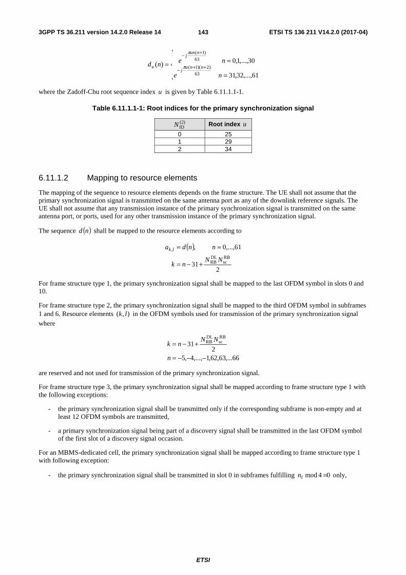
3GPP TS 36.211 version 14.2.0 Release 14 ETSI TS 136 211 V14.2.0 (2017-04)
ETSI
143
⎪⎩
⎪⎨
⎧
=
== ++−
+−
61,...,32,31
30,...,1,0)(63
)2)(1(
63
)1(
ne
nend nnuj
nunj
u π
π
where the Zadoff-Chu root sequence index u is given by Table 6.11.1.1-1.
Table 6.11.1.1-1: Root indices for the primary synchronization signal
(2)IDN Root index u
0 25 1 29 2 34
6.11.1.2 Mapping to resource elements
The mapping of the sequence to resource elements depends on the frame structure. The UE shall not assume that the primary synchronization signal is transmitted on the same antenna port as any of the downlink reference signals. The UE shall not assume that any transmission instance of the primary synchronization signal is transmitted on the same antenna port, or ports, used for any other transmission instance of the primary synchronization signal.
The sequence ( )nd shall be mapped to the resource elements according to
( )
231
61,...,0 ,
RBsc
DLRB
,
NNnk
nnda lk
+−=
==
For frame structure type 1, the primary synchronization signal shall be mapped to the last OFDM symbol in slots 0 and 10.
For frame structure type 2, the primary synchronization signal shall be mapped to the third OFDM symbol in subframes 1 and 6. Resource elements ),( lk in the OFDM symbols used for transmission of the primary synchronization signal
where
66,...63,62,1,...,4,52
31RBsc
DLRB
−−−=
+−=
n
NNnk
are reserved and not used for transmission of the primary synchronization signal.
For frame structure type 3, the primary synchronization signal shall be mapped according to frame structure type 1 with the following exceptions:
- the primary synchronization signal shall be transmitted only if the corresponding subframe is non-empty and at least 12 OFDM symbols are transmitted,
- a primary synchronization signal being part of a discovery signal shall be transmitted in the last OFDM symbol of the first slot of a discovery signal occasion.
For an MBMS-dedicated cell, the primary synchronization signal shall be mapped according to frame structure type 1 with following exception:
- the primary synchronization signal shall be transmitted in slot 0 in subframes fulfilling 04modf =n only,
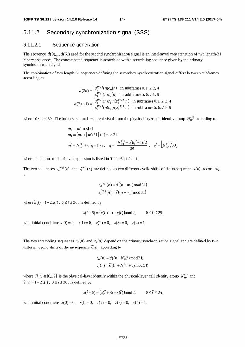
3GPP TS 36.211 version 14.2.0 Release 14 ETSI TS 136 211 V14.2.0 (2017-04)
ETSI
144
6.11.2 Secondary synchronization signal (SSS)
6.11.2.1 Sequence generation
The sequence )61(),...,0( dd used for the second synchronization signal is an interleaved concatenation of two length-31
binary sequences. The concatenated sequence is scrambled with a scrambling sequence given by the primary synchronization signal.
The combination of two length-31 sequences defining the secondary synchronization signal differs between subframes according to
( )( )( ) ( )( ) ( )⎪⎩
⎪⎨⎧
=+
⎪⎩
⎪⎨⎧
=
9 8, 7, 6, 5, subframesin )(
4 3, 2, 1, 0, subframesin )()12(
9 8, 7, 6, 5, subframesin )(
4 3, 2, 1, 0, subframesin )()2(
)(11
)(0
)(11
)(1
0)(
1
0)(
0
10
01
1
0
nzncns
nzncnsnd
ncns
ncnsnd
mm
mm
m
m
where 300 ≤≤ n . The indices 0m and 1m are derived from the physical-layer cell-identity group (1)IDN according to
⎣ ⎦( )
⎣ ⎦30,30
2)1(,2)1(
31mod131
31mod
(1)ID
(1)ID(1)
ID
01
0
NqqqN
qqqNm
mmm
mm
=′⎥⎥⎦
⎥
⎢⎢⎣
⎢ +′′+=++=′
+′+=′=
where the output of the above expression is listed in Table 6.11.2.1-1.
The two sequences )()(0
0 ns m and )()(1
1 ns m are defined as two different cyclic shifts of the m-sequence )(~ ns according
to
( )( )31mod)(~)(
31mod)(~)(
1)(
1
0)(
0
1
0
mnsns
mnsnsm
m
+=
+=
where )(21)(~ ixis −= , 300 ≤≤ i , is defined by
( ) 250 ,2mod)()2()5( ≤≤++=+ iixixix
with initial conditions 1)4(,0)3(,0)2(,0)1(,0)0( ===== xxxxx .
The two scrambling sequences )(0 nc and )(1 nc depend on the primary synchronization signal and are defined by two
different cyclic shifts of the m-sequence )(~ nc according to
)31mod)3((~)(
)31mod)((~)()2(
ID1
)2(ID0
++=
+=
Nncnc
Nncnc
where { }2,1,0)2(ID ∈N is the physical-layer identity within the physical-layer cell identity group (1)
IDN and
)(21)(~ ixic −= , 300 ≤≤ i , is defined by
( ) 250 ,2mod)()3()5( ≤≤++=+ iixixix
with initial conditions 1)4(,0)3(,0)2(,0)1(,0)0( ===== xxxxx .

3GPP TS 36.211 version 14.2.0 Release 14 ETSI TS 136 211 V14.2.0 (2017-04)
ETSI
145
The scrambling sequences )()(1
0 nz m and )()(1
1 nz m are defined by a cyclic shift of the m-sequence )(~ nz according to
)31mod))8mod(((~)( 0)(
10 mnznz m +=
)31mod))8mod(((~)( 1)(
11 mnznz m +=
where 0m and 1m are obtained from Table 6.11.2.1-1 and )(21)(~ ixiz −= , 300 ≤≤ i , is defined by
( ) 250 ,2mod)()1()2()4()5( ≤≤++++++=+ iixixixixix
with initial conditions 1)4(,0)3(,0)2(,0)1(,0)0( ===== xxxxx .
Table 6.11.2.1-1: Mapping between physical-layer cell-identity group (1)IDN and the indices 0m and 1m
(1)IDN 0m 1m
(1)IDN 0m 1m
(1)IDN 0m 1m
(1)IDN 0m 1m
(1)IDN 0m 1m
0 0 1 34 4 6 68 9 12 102 15 19 136 22 27 1 1 2 35 5 7 69 10 13 103 16 20 137 23 28 2 2 3 36 6 8 70 11 14 104 17 21 138 24 29 3 3 4 37 7 9 71 12 15 105 18 22 139 25 30 4 4 5 38 8 10 72 13 16 106 19 23 140 0 6 5 5 6 39 9 11 73 14 17 107 20 24 141 1 7 6 6 7 40 10 12 74 15 18 108 21 25 142 2 8 7 7 8 41 11 13 75 16 19 109 22 26 143 3 9 8 8 9 42 12 14 76 17 20 110 23 27 144 4 10 9 9 10 43 13 15 77 18 21 111 24 28 145 5 11
10 10 11 44 14 16 78 19 22 112 25 29 146 6 12 11 11 12 45 15 17 79 20 23 113 26 30 147 7 13 12 12 13 46 16 18 80 21 24 114 0 5 148 8 14 13 13 14 47 17 19 81 22 25 115 1 6 149 9 15 14 14 15 48 18 20 82 23 26 116 2 7 150 10 16 15 15 16 49 19 21 83 24 27 117 3 8 151 11 17 16 16 17 50 20 22 84 25 28 118 4 9 152 12 18 17 17 18 51 21 23 85 26 29 119 5 10 153 13 19 18 18 19 52 22 24 86 27 30 120 6 11 154 14 20 19 19 20 53 23 25 87 0 4 121 7 12 155 15 21 20 20 21 54 24 26 88 1 5 122 8 13 156 16 22 21 21 22 55 25 27 89 2 6 123 9 14 157 17 23 22 22 23 56 26 28 90 3 7 124 10 15 158 18 24 23 23 24 57 27 29 91 4 8 125 11 16 159 19 25 24 24 25 58 28 30 92 5 9 126 12 17 160 20 26 25 25 26 59 0 3 93 6 10 127 13 18 161 21 27 26 26 27 60 1 4 94 7 11 128 14 19 162 22 28 27 27 28 61 2 5 95 8 12 129 15 20 163 23 29 28 28 29 62 3 6 96 9 13 130 16 21 164 24 30 29 29 30 63 4 7 97 10 14 131 17 22 165 0 7 30 0 2 64 5 8 98 11 15 132 18 23 166 1 8 31 1 3 65 6 9 99 12 16 133 19 24 167 2 9 32 2 4 66 7 10 100 13 17 134 20 25 - - - 33 3 5 67 8 11 101 14 18 135 21 26 - - -
6.11.2.2 Mapping to resource elements
The mapping of the sequence to resource elements depends on the frame structure. In a subframe for frame structure type 1 and 3 and in a half-frame for frame structure type 2, the same antenna port as for the primary synchronization signal shall be used for the secondary synchronization signal.
The sequence ( )nd shall be mapped to resource elements according to

3GPP TS 36.211 version 14.2.0 Release 14 ETSI TS 136 211 V14.2.0 (2017-04)
ETSI
146
( )
⎪⎪
⎩
⎪⎪
⎨
⎧
−−−−
=
+−=
==
cell dedicated-MBMSan for ed transmittis PSS the whereslotsin 2
3 typestructure framefor ed transmittis PSS the whereslotsin 2
2 typestructure framefor 11 and 1 slotsin 1
cell dedicated-MBMSan for except 1 typestructure framefor 10 and 0 slotsin 2
231
61,...,0 ,
DLsymb
DLsymb
DLsymb
DLsymb
RBsc
DLRB
,
N
N
N
N
l
NNnk
nnda lk
Resource elements ),( lk where
66,...63,62,1,...,4,5
cell dedicated-MBMSan for dtransmitte is PSS the whereslotsin 2
3 typestructure framefor dtransmitte is PSS the whereslotsin 2
2 typestructure framefor 11 and 1 slotsin 1
cell dedicated-MBMSan for except 1 typestructure framefor 10 and 0 slotsin 2
231
DLsymb
DLsymb
DLsymb
DLsymb
RBsc
DLRB
−−−=
⎪⎪
⎩
⎪⎪
⎨
⎧
−−−−
=
+−=
n
N
N
N
N
l
NNnk
are reserved and not used for transmission of the secondary synchronization signal.
6.11A Discovery signal A discovery signal occasion for a cell consists of a period with a duration of
- one to five consecutive subframes for frame structure type 1
- two to five consecutive subframes for frame structure type 2
- 12 OFDM symbols within one non-empty subframe for frame structure type 3
where the UE in the downlink subframes may assume presence of a discovery signal consisting of
- cell-specific reference signals on antenna port 0 in all downlink subframes and in DwPTS of all special subframes in the period for frame structure type 1 and 2
- cell specific reference signals on antenna port 0 when higher layer parameters indicate only one configured antenna port for cell specific reference signals for a serving cell using frame structure type 3
- cell specific reference signals on antenna port 0 and antenna port 1 when higher layer parameters indicate at least two configured antenna ports for cell specific reference signals for a serving cell using frame structure type 3
- cell specific reference signals on antenna port 0 and antenna port 1 when higher layer configured parameter presenceAntennaPort1 is signalled to be 1, for a neighbour cell when using frame structure type 3
- primary synchronization signal in the first subframe of the period for frame structure types 1 and 3 or the second subframe of the period for frame structure type 2,
- secondary synchronization signal in the first subframe of the period, and
- non-zero-power CSI reference signals in zero or more subframes in the period. The configuration of non-zero-power CSI reference signals part of the discovery signal is obtained as described in clause 6.10.5.2
For frame structures 1 and 2 the UE may assume a discovery signal occasion once every dmtc-Periodicity.
For frame structure type 3, the UE may assume a discovery signal occasion may occur in any subframe within the discovery signals measurement timing configuration in clause 5.5.2.10 of [9].
For frame structure type 3, simultaneous transmission of a discovery signal and PDSCH/PDCCH/EPDCCH may occur in subframes 0 and 5 only.

3GPP TS 36.211 version 14.2.0 Release 14 ETSI TS 136 211 V14.2.0 (2017-04)
ETSI
147
For frame structure type 3, the UE may assume that a discovery signal occasion occurs in the first subframe containing a primary synchronization signal, secondary synchronization signal and cell-specific reference signals within the discovery measurement timing configuration in clause 5.5.2.10 of [9].
6.12 OFDM baseband signal generation
The time-continuous signal ( )ts pl
)( on antenna port p in OFDM symbol l in a downlink slot is defined by
( ) ( )
⎣ ⎦
( )⎡ ⎤∑∑
=
−Δ−
−=
−Δ ⋅+⋅= +−
2/
1
2)(,
1
2/
2)(,
)(
RBsc
DLRB
s,CP)(
RBsc
DLRB
s,CP)(
NN
k
TNtfkjplk
NNk
TNtfkjplk
pl
ll eaeats ππ
for ( ) s,CP0 TNNt l ×+<≤ where ⎣ ⎦2RBsc
DLRB
)( NNkk +=− and ⎣ ⎦ 12RBsc
DLRB
)( −+=+ NNkk . The variable N equals
2048 for kHz 15=Δf subcarrier spacing, 4096 for kHz 5.7=Δf subcarrier spacing, and 24576 for kHz 25.1=Δf
subcarrier spacing.
The OFDM symbols in a slot shall be transmitted in increasing order of l , starting with 0=l , where OFDM symbol
0>l starts at time ∑−
=′ ′ +1
0 s,CP )(l
l l TNN within the slot. In case the first OFDM symbol(s) in a slot use normal cyclic
prefix and the remaining OFDM symbols use extended cyclic prefix, the starting position the OFDM symbols with extended cyclic prefix shall be identical to those in a slot where all OFDM symbols use extended cyclic prefix. Thus there will be a part of the time slot between the two cyclic prefix regions where the transmitted signal is not specified. For kHz 25.1=Δf , there is one OFDM symbol per slot and one slot per subframe.
Table 6.12-1 lists the value of lN ,CP that shall be used. Note that different OFDM symbols within a slot in some cases
have different cyclic prefix lengths.
In case NB-IoT is supported, the OFDM baseband signal generation is defined in subclause 10.2.8.
Table 6.12-1: OFDM parameters
Configuration Cyclic prefix length lN ,CP
Normal cyclic prefix kHz 15=Δf 0for 160 =l
6,...,2,1for 144 =l
Extended cyclic prefix
kHz 15=Δf 5,...,1,0for 512 =l
kHz 5.7=Δf 2,1,0for 1024 =l
kHz 25.1=Δf 0for 6144 =l
6.13 Modulation and upconversion Modulation and upconversion to the carrier frequency of the complex-valued OFDM baseband signal for each antenna port is shown in Figure 6.13-1. The filtering required prior to transmission is defined by the requirements in 3GPP TS 36.104 [6].
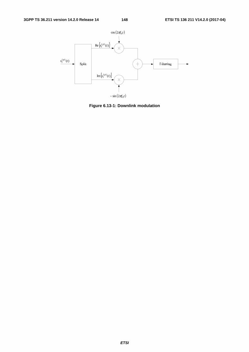
3GPP TS 36.211 version 14.2.0 Release 14 ETSI TS 136 211 V14.2.0 (2017-04)
ETSI
148
{ })(Re )( ts pl
{ })(Im )( ts pl
( )tf02cos π
( )tf02sin π−
)()( ts pl
Figure 6.13-1: Downlink modulation

3GPP TS 36.211 version 14.2.0 Release 14 ETSI TS 136 211 V14.2.0 (2017-04)
ETSI
149
7 Generic functions
7.1 Modulation mapper The modulation mapper takes binary digits, 0 or 1, as input and produces complex-valued modulation symbols, x as output.
7.1.1 BPSK
In case of BPSK modulation, a single bit, )(ib , is mapped to a complex-valued modulation symbol x=I+jQ according to
Table 7.1.1-1.
Table 7.1.1-1: BPSK modulation mapping
)(ib I Q
0 21 21
1 21− 21−
7.1.2 QPSK
In case of QPSK modulation, pairs of bits, )1(),( +ibib , are mapped to complex-valued modulation symbols x
according to Table 7.1.2-1 where jQIx += unless “MUST interference presence and power ratio (MUSTIdx)” is
signalled in the associated DCI and is not ‘00’ in which case ( ) ( )dQcedIcex jj −+−= + πφπφ )2/1( 10 where c and d are
determined from MUSTIdx using Table 7.1.2-2, and each { }1,0, 10 ∈φφ is selected by eNB independently of
)1(),( +ibib .
Table 7.1.2-1: QPSK modulation mapping
)1(),( +ibib I Q
00 21 21
01 21 21−
10 21− 21
11 21− 21−
Table 7.1.2-2: Values for c and d for QPSK
MUSTIdx c d
01 5/1 2
10 29/2 ( )22/5
11 578/17 ( )27/23
7.1.3 16QAM
In case of 16QAM modulation, quadruplets of bits, )3(),2(),1(),( +++ ibibibib , are mapped to complex-valued
modulation symbols x according to Table 7.1.3-1 where jQIx += unless “MUST interference presence and power
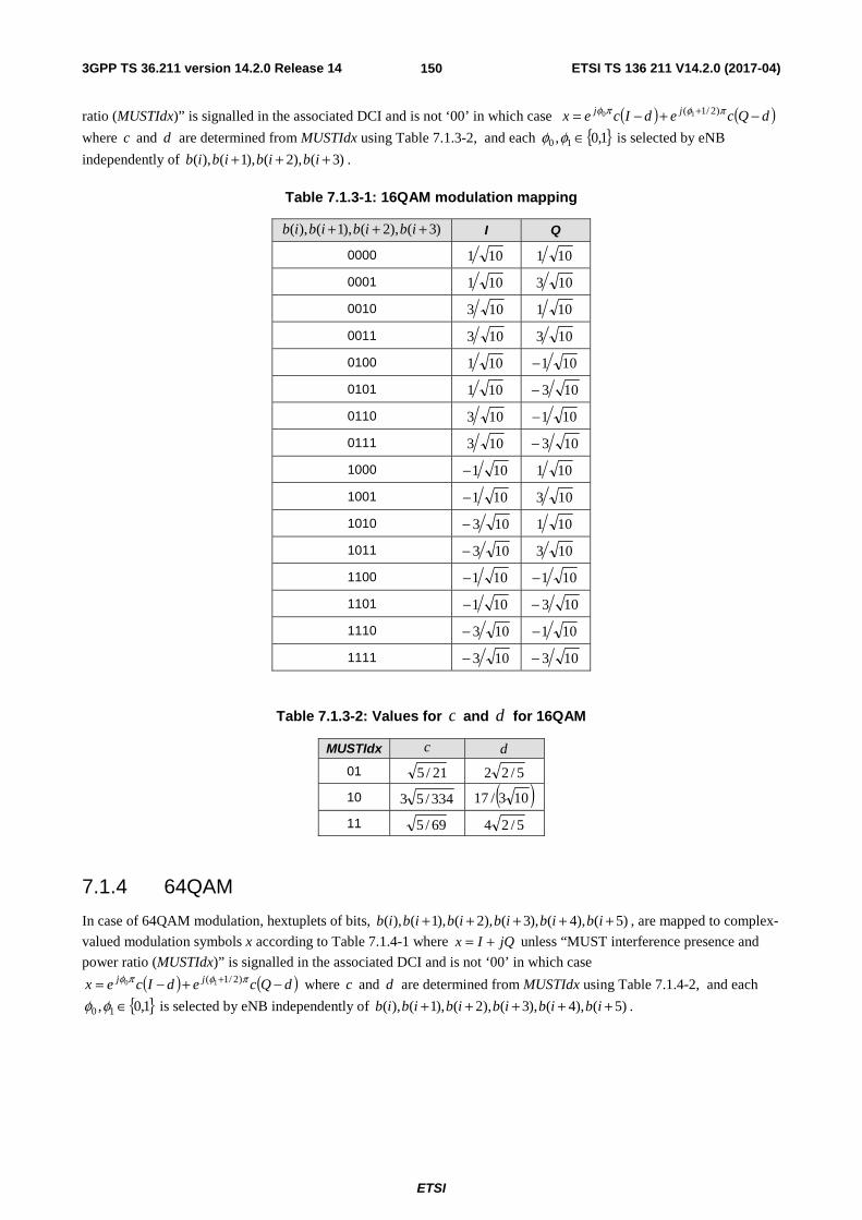
3GPP TS 36.211 version 14.2.0 Release 14 ETSI TS 136 211 V14.2.0 (2017-04)
ETSI
150
ratio (MUSTIdx)” is signalled in the associated DCI and is not ‘00’ in which case ( ) ( )dQcedIcex jj −+−= + πφπφ )2/1( 10
where c and d are determined from MUSTIdx using Table 7.1.3-2, and each { }1,0, 10 ∈φφ is selected by eNB
independently of )3(),2(),1(),( +++ ibibibib .
Table 7.1.3-1: 16QAM modulation mapping
)3(),2(),1(),( +++ ibibibib I Q
0000 101 101
0001 101 103
0010 103 101
0011 103 103
0100 101 101−
0101 101 103−
0110 103 101−
0111 103 103−
1000 101− 101
1001 101− 103
1010 103− 101
1011 103− 103
1100 101− 101−
1101 101− 103−
1110 103− 101−
1111 103− 103−
Table 7.1.3-2: Values for c and d for 16QAM
MUSTIdx c d
01 21/5 5/22
10 334/53 ( )103/17
11 69/5 5/24
7.1.4 64QAM
In case of 64QAM modulation, hextuplets of bits, )5(),4(),3(),2(),1(),( +++++ ibibibibibib , are mapped to complex-
valued modulation symbols x according to Table 7.1.4-1 where jQIx += unless “MUST interference presence and
power ratio (MUSTIdx)” is signalled in the associated DCI and is not ‘00’ in which case
( ) ( )dQcedIcex jj −+−= + πφπφ )2/1( 10 where c and d are determined from MUSTIdx using Table 7.1.4-2, and each
{ }1,0, 10 ∈φφ is selected by eNB independently of )5(),4(),3(),2(),1(),( +++++ ibibibibibib .

3GPP TS 36.211 version 14.2.0 Release 14 ETSI TS 136 211 V14.2.0 (2017-04)
ETSI
151
Table 7.1.4-1: 64QAM modulation mapping
)5(),4(),3(),2(),1(),( +++++ ibibibibibib I Q )5(),4(),3(),2(),1(),( +++++ ibibibibibib I Q
000000 423 423 100000 423− 423
000001 423 421 100001 423− 421
000010 421 423 100010 421− 423
000011 421 421 100011 421− 421
000100 423 425 100100 423− 425
000101 423 427 100101 423− 427
000110 421 425 100110 421− 425
000111 421 427 100111 421− 427
001000 425 423 101000 425− 423
001001 425 421 101001 425− 421
001010 427 423 101010 427− 423
001011 427 421 101011 427− 421
001100 425 425 101100 425− 425
001101 425 427 101101 425− 427
001110 427 425 101110 427− 425
001111 427 427 101111 427− 427
010000 423 423− 110000 423− 423−
010001 423 421− 110001 423− 421−
010010 421 423− 110010 421− 423−
010011 421 421− 110011 421− 421−
010100 423 425− 110100 423− 425−
010101 423 427− 110101 423− 427−
010110 421 425− 110110 421− 425−
010111 421 427− 110111 421− 427−
011000 425 423− 111000 425− 423−
011001 425 421− 111001 425− 421−
011010 427 423− 111010 427− 423−
011011 427 421− 111011 427− 421−
011100 425 425− 111100 425− 425−
011101 425 427− 111101 425− 427−
011110 427 425− 111110 427− 425−
011111 427 427− 111111 427− 427−

3GPP TS 36.211 version 14.2.0 Release 14 ETSI TS 136 211 V14.2.0 (2017-04)
ETSI
152
Table 7.1.4-2: Values for c and d for 64QAM
MUSTIdx c d
01 85/21 2/214
10 34/7 3/143
11 55/7 7/62
7.1.5 256QAM
In case of 256QAM modulation, octuplets of bits, )7(),6(),5(),4(),3(),2(),1(),( +++++++ ibibibibibibibib , are
mapped to complex-valued modulation symbols ( ) 170jQIx += according to Table 7.1.5-1.

3GPP TS 36.211 version 14.2.0 Release 14 ETSI TS 136 211 V14.2.0 (2017-04)
ETSI
153
Table 7.1.5-1: 256QAM modulation mapping
)7(),...,( +ibib I Q )7(),...,( +ibib I Q )7(),...,( +ibib I Q )7(),...,( +ibib I Q 00000000 5 5 01000000 5 -5 10000000 -5 5 11000000 -5 -5 00000001 5 7 01000001 5 -7 10000001 -5 7 11000001 -5 -7 00000010 7 5 01000010 7 -5 10000010 -7 5 11000010 -7 -5 00000011 7 7 01000011 7 -7 10000011 -7 7 11000011 -7 -7 00000100 5 3 01000100 5 -3 10000100 -5 3 11000100 -5 -3 00000101 5 1 01000101 5 -1 10000101 -5 1 11000101 -5 -1 00000110 7 3 01000110 7 -3 10000110 -7 3 11000110 -7 -3 00000111 7 1 01000111 7 -1 10000111 -7 1 11000111 -7 -1 00001000 3 5 01001000 3 -5 10001000 -3 5 11001000 -3 -5 00001001 3 7 01001001 3 -7 10001001 -3 7 11001001 -3 -7 00001010 1 5 01001010 1 -5 10001010 -1 5 11001010 -1 -5 00001011 1 7 01001011 1 -7 10001011 -1 7 11001011 -1 -7 00001100 3 3 01001100 3 -3 10001100 -3 3 11001100 -3 -3 00001101 3 1 01001101 3 -1 10001101 -3 1 11001101 -3 -1 00001110 1 3 01001110 1 -3 10001110 -1 3 11001110 -1 -3 00001111 1 1 01001111 1 -1 10001111 -1 1 11001111 -1 -1 00010000 5 11 01010000 5 -11 10010000 -5 11 11010000 -5 -11 00010001 5 9 01010001 5 -9 10010001 -5 9 11010001 -5 -9 00010010 7 11 01010010 7 -11 10010010 -7 11 11010010 -7 -11 00010011 7 9 01010011 7 -9 10010011 -7 9 11010011 -7 -9 00010100 5 13 01010100 5 -13 10010100 -5 13 11010100 -5 -13 00010101 5 15 01010101 5 -15 10010101 -5 15 11010101 -5 -15 00010110 7 13 01010110 7 -13 10010110 -7 13 11010110 -7 -13 00010111 7 15 01010111 7 -15 10010111 -7 15 11010111 -7 -15 00011000 3 11 01011000 3 -11 10011000 -3 11 11011000 -3 -11 00011001 3 9 01011001 3 -9 10011001 -3 9 11011001 -3 -9 00011010 1 11 01011010 1 -11 10011010 -1 11 11011010 -1 -11 00011011 1 9 01011011 1 -9 10011011 -1 9 11011011 -1 -9 00011100 3 13 01011100 3 -13 10011100 -3 13 11011100 -3 -13 00011101 3 15 01011101 3 -15 10011101 -3 15 11011101 -3 -15 00011110 1 13 01011110 1 -13 10011110 -1 13 11011110 -1 -13 00011111 1 15 01011111 1 -15 10011111 -1 15 11011111 -1 -15 00100000 11 5 01100000 11 -5 10100000 -11 5 11100000 -11 -5 00100001 11 7 01100001 11 -7 10100001 -11 7 11100001 -11 -7 00100010 9 5 01100010 9 -5 10100010 -9 5 11100010 -9 -5 00100011 9 7 01100011 9 -7 10100011 -9 7 11100011 -9 -7 00100100 11 3 01100100 11 -3 10100100 -11 3 11100100 -11 -3 00100101 11 1 01100101 11 -1 10100101 -11 1 11100101 -11 -1 00100110 9 3 01100110 9 -3 10100110 -9 3 11100110 -9 -3 00100111 9 1 01100111 9 -1 10100111 -9 1 11100111 -9 -1 00101000 13 5 01101000 13 -5 10101000 -13 5 11101000 -13 -5 00101001 13 7 01101001 13 -7 10101001 -13 7 11101001 -13 -7 00101010 15 5 01101010 15 -5 10101010 -15 5 11101010 -15 -5 00101011 15 7 01101011 15 -7 10101011 -15 7 11101011 -15 -7 00101100 13 3 01101100 13 -3 10101100 -13 3 11101100 -13 -3 00101101 13 1 01101101 13 -1 10101101 -13 1 11101101 -13 -1 00101110 15 3 01101110 15 -3 10101110 -15 3 11101110 -15 -3 00101111 15 1 01101111 15 -1 10101111 -15 1 11101111 -15 -1 00110000 11 11 01110000 11 -11 10110000 -11 11 11110000 -11 -11 00110001 11 9 01110001 11 -9 10110001 -11 9 11110001 -11 -9 00110010 9 11 01110010 9 -11 10110010 -9 11 11110010 -9 -11 00110011 9 9 01110011 9 -9 10110011 -9 9 11110011 -9 -9 00110100 11 13 01110100 11 -13 10110100 -11 13 11110100 -11 -13 00110101 11 15 01110101 11 -15 10110101 -11 15 11110101 -11 -15 00110110 9 13 01110110 9 -13 10110110 -9 13 11110110 -9 -13 00110111 9 15 01110111 9 -15 10110111 -9 15 11110111 -9 -15 00111000 13 11 01111000 13 -11 10111000 -13 11 11111000 -13 -11 00111001 13 9 01111001 13 -9 10111001 -13 9 11111001 -13 -9 00111010 15 11 01111010 15 -11 10111010 -15 11 11111010 -15 -11 00111011 15 9 01111011 15 -9 10111011 -15 9 11111011 -15 -9 00111100 13 13 01111100 13 -13 10111100 -13 13 11111100 -13 -13 00111101 13 15 01111101 13 -15 10111101 -13 15 11111101 -13 -15

3GPP TS 36.211 version 14.2.0 Release 14 ETSI TS 136 211 V14.2.0 (2017-04)
ETSI
154
00111110 15 13 01111110 15 -13 10111110 -15 13 11111110 -15 -13 00111111 15 15 01111111 15 -15 10111111 -15 15 11111111 -15 -15
7.2 Pseudo-random sequence generation Pseudo-random sequences are defined by a length-31 Gold sequence. The output sequence )(nc of length PNM ,
where 1,...,1,0 PN −= Mn , is defined by
( )( )( ) 2mod)()1()2()3()31(
2mod)()3()31(
2mod)()()(
22222
111
21
nxnxnxnxnx
nxnxnx
NnxNnxnc CC
++++++=+++=+
+++=
where 1600=CN and the first m-sequence shall be initialized with 30,...,2,1,0)(,1)0( 11 === nnxx . The initialization
of the second m-sequence is denoted by ∑ =⋅=
30
0 2init 2)(i
iixc with the value depending on the application of the
sequence.
8 Timing
8.1 Uplink-downlink frame timing Transmission of the uplink radio frame number i from the UE shall start soffsetTA TA )( TNN ×+ seconds before the start
of the corresponding downlink radio frame at the UE, where 40960 TA ≤≤ N if the UE is configured with a SCG and
205120 TA ≤≤ N otherwise. For frame structure type 1 0offsetTA =N and for frame structure type 2 624offsetTA =N
unless stated otherwise in [4]. Note that not all slots in a radio frame may be transmitted. One example hereof is TDD, where only a subset of the slots in a radio frame is transmitted.
( ) seconds soffsetTA TA TNN ⋅+
Figure 8.1-1: Uplink-downlink timing relation
3GPP TS 36.211 version 14.2.0 Release 14 ETSI TS 136 211 V14.2.0 (2017-04)
ETSI
155
9 Sidelink
9.1 Overview A sidelink is used for ProSe direct communication and ProSe direct discovery between UEs.
9.1.1 Physical channels
A sidelink physical channel corresponds to a set of resource elements carrying information originating from higher layers and is the interface defined between 3GPP TS 36.212 [3] and the present document 3GPP TS 36.211. The following sidelink physical channels are defined:
- Physical Sidelink Shared Channel, PSSCH
- Physical Sidelink Control Channel, PSCCH
- Physical Sidelink Discovery Channel, PSDCH
- Physical Sidelink Broadcast Channel, PSBCH
Generation of the baseband signal representing the different physical sidelink channels is illustrated in Figrue 5.3-1.
9.1.2 Physical signals
A sidelink physical signal is used by the physical layer but does not carry information originating from higher layers. The following sidelink physical signals are defined:
- Demodulation reference signal
- Synchronization signal
9.1.3 Handling of simultaneous sidelink and uplink/downlink transmissions
For a given frequency, on an uplink subframe included in discTxGapConfig [9], a UE shall not transmit an uplink transmission that is not a PRACH transmission and that is partly or completely overlapping in time with a PSDCH transmission or a SLSS transmission for PSDCH by the same UE. Else, for a given carrier frequency and sidelink transmission mode 1 or 2 or sidelink discovery, a UE shall not transmit a sidelink signal or channel overlapping partly or completely in time with an uplink transmission from the same UE.
For a given carrier frequency, no PSDCH, PSCCH, or PSSCH transmission shall occur from a UE in a sidelink subframe configured for synchronization purposes by the higher-layer parameters
- syncOffsetIndicator1 or syncOffsetIndicator2 in [9] if the UE has no serving cell fulfilling the S criterion according to [10, clause 5.2.3.2], or
- syncOffsetIndicator in commSyncConfig or discSyncConfig which includes txParameters in [9] if the UE has a serving cell fulfilling the S criterion according to [10, clause 5.2.3.2]. The UE may assume the same configuration in commSyncConfig and discSyncConfig.
For a given carrier frequency, with the exception of PSSCH transmissions with transmission mode 1 and same sidelink cyclic prefix as PUSCH, no sidelink transmissions shall occur in sidelink subframe n from a UE if uplink SRS is transmitted from the same UE in uplink subframe n .
In case of a UE capable of transmission on multiple carriers, sidelink transmission may only occur on a single carrier frequency at a given time.
A UE with limited transmission capabilities, on an uplink subframe included in discTxGapConfig [9], shall first prioritize a PSDCH transmission or a SLSS transmission for PSDCH over an uplink transmission that is not a PRACH transmission. Else, a UE with limited transmission capabilities shall at a given time first prioritize uplink transmissions, followed by sidelink transmission mode 1 or 2 or sidelink discovery.
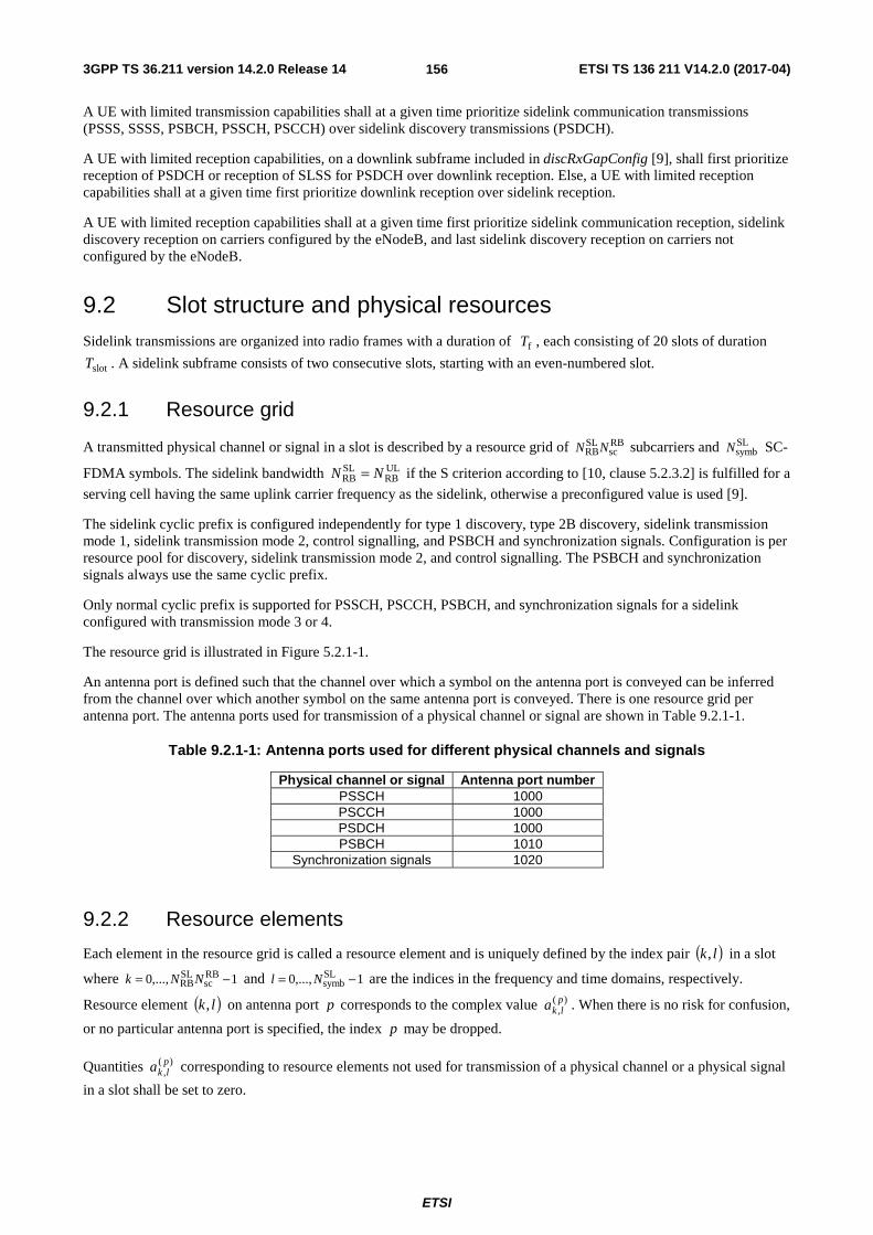
3GPP TS 36.211 version 14.2.0 Release 14 ETSI TS 136 211 V14.2.0 (2017-04)
ETSI
156
A UE with limited transmission capabilities shall at a given time prioritize sidelink communication transmissions (PSSS, SSSS, PSBCH, PSSCH, PSCCH) over sidelink discovery transmissions (PSDCH).
A UE with limited reception capabilities, on a downlink subframe included in discRxGapConfig [9], shall first prioritize reception of PSDCH or reception of SLSS for PSDCH over downlink reception. Else, a UE with limited reception capabilities shall at a given time first prioritize downlink reception over sidelink reception.
A UE with limited reception capabilities shall at a given time first prioritize sidelink communication reception, sidelink discovery reception on carriers configured by the eNodeB, and last sidelink discovery reception on carriers not configured by the eNodeB.
9.2 Slot structure and physical resources Sidelink transmissions are organized into radio frames with a duration of fT , each consisting of 20 slots of duration
slotT . A sidelink subframe consists of two consecutive slots, starting with an even-numbered slot.
9.2.1 Resource grid
A transmitted physical channel or signal in a slot is described by a resource grid of RBsc
SLRBNN subcarriers and SL
symbN SC-
FDMA symbols. The sidelink bandwidth ULRB
SLRB NN = if the S criterion according to [10, clause 5.2.3.2] is fulfilled for a
serving cell having the same uplink carrier frequency as the sidelink, otherwise a preconfigured value is used [9].
The sidelink cyclic prefix is configured independently for type 1 discovery, type 2B discovery, sidelink transmission mode 1, sidelink transmission mode 2, control signalling, and PSBCH and synchronization signals. Configuration is per resource pool for discovery, sidelink transmission mode 2, and control signalling. The PSBCH and synchronization signals always use the same cyclic prefix.
Only normal cyclic prefix is supported for PSSCH, PSCCH, PSBCH, and synchronization signals for a sidelink configured with transmission mode 3 or 4.
The resource grid is illustrated in Figure 5.2.1-1.
An antenna port is defined such that the channel over which a symbol on the antenna port is conveyed can be inferred from the channel over which another symbol on the same antenna port is conveyed. There is one resource grid per antenna port. The antenna ports used for transmission of a physical channel or signal are shown in Table 9.2.1-1.
Table 9.2.1-1: Antenna ports used for different physical channels and signals
Physical channel or signal Antenna port number PSSCH 1000 PSCCH 1000 PSDCH 1000 PSBCH 1010
Synchronization signals 1020
9.2.2 Resource elements
Each element in the resource grid is called a resource element and is uniquely defined by the index pair ( )lk, in a slot
where 1,...,0 RBsc
SLRB −= NNk and 1,...,0 SL
symb −= Nl are the indices in the frequency and time domains, respectively.
Resource element ( )lk, on antenna port p corresponds to the complex value )(,plka . When there is no risk for confusion,
or no particular antenna port is specified, the index p may be dropped.
Quantities )(,plka corresponding to resource elements not used for transmission of a physical channel or a physical signal
in a slot shall be set to zero.
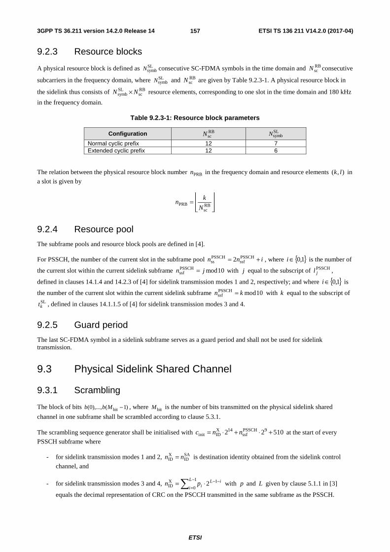
3GPP TS 36.211 version 14.2.0 Release 14 ETSI TS 136 211 V14.2.0 (2017-04)
ETSI
157
9.2.3 Resource blocks
A physical resource block is defined as SLsymbN consecutive SC-FDMA symbols in the time domain and RB
scN consecutive
subcarriers in the frequency domain, where SLsymbN and RB
scN are given by Table 9.2.3-1. A physical resource block in
the sidelink thus consists of RBsc
SLsymb NN × resource elements, corresponding to one slot in the time domain and 180 kHz
in the frequency domain.
Table 9.2.3-1: Resource block parameters
Configuration RBscN SL
symbN
Normal cyclic prefix 12 7 Extended cyclic prefix 12 6
The relation between the physical resource block number PRBn in the frequency domain and resource elements ),( lk in
a slot is given by
⎥⎥⎦
⎥
⎢⎢⎣
⎢=
RBsc
PRBN
kn
9.2.4 Resource pool
The subframe pools and resource block pools are defined in [4].
For PSSCH, the number of the current slot in the subframe pool inn += PSSCHssf
PSSCHss 2 , where { }1,0∈i is the number of
the current slot within the current sidelink subframe 10modPSSCHssf jn = with j equal to the subscript of PSSCH
jl ,
defined in clauses 14.1.4 and 14.2.3 of [4] for sidelink transmission modes 1 and 2, respectively; and where { }1,0∈i is
the number of the current slot within the current sidelink subframe 10modPSSCHssf kn = with k equal to the subscript of
SLkt , defined in clauses 14.1.1.5 of [4] for sidelink transmission modes 3 and 4.
9.2.5 Guard period
The last SC-FDMA symbol in a sidelink subframe serves as a guard period and shall not be used for sidelink transmission.
9.3 Physical Sidelink Shared Channel
9.3.1 Scrambling
The block of bits )1(),...,0( bit −Mbb , where bitM is the number of bits transmitted on the physical sidelink shared
channel in one subframe shall be scrambled according to clause 5.3.1.
The scrambling sequence generator shall be initialised with 51022 9PSSCHssf
14XIDinit +⋅+⋅= nnc at the start of every
PSSCH subframe where
- for sidelink transmission modes 1 and 2, SAID
XID nn = is destination identity obtained from the sidelink control
channel, and
- for sidelink transmission modes 3 and 4, ∑−
=−−⋅=
1
0
1XID 2
L
i
iLipn with p and L given by clause 5.1.1 in [3]
equals the decimal representation of CRC on the PSCCH transmitted in the same subframe as the PSSCH.

3GPP TS 36.211 version 14.2.0 Release 14 ETSI TS 136 211 V14.2.0 (2017-04)
ETSI
158
9.3.2 Modulation
Modulation shall be done according to clause 5.3.2. Table 9.3.2-1 specifies the modulation mappings applicable for the physical sidelink shared channel.
Table 9.3.2-1: PSSCH modulation schemes
Physical channel Modulation schemes PSSCH QPSK, 16QAM
9.3.3 Layer mapping
Layer mapping shall be done according to clause 5.3.2A assuming a single antenna port, 1=υ .
9.3.4 Transform precoding
Transform precoding shall be done according to clause 5.3.3 with PUSCHRBM and PUSCH
scM replaced by PSSCHRBM and
PSSCHscM , respectively.
9.3.5 Precoding
Precoding shall be done according to clause 5.3.3A assuming a single antenna port, 1=υ .
9.3.6 Mapping to physical resources
The block of complex-valued symbols )1(),...,0( apsymb −Mzz shall be multiplied with the amplitude scaling factor PSSCHβ
in order to conform to the transmit power PSSCHP specified in [4], and mapped in sequence starting with )0(z to
physical resource blocks on antenna port p and assigned for transmission of PSSCH. The mapping to resource
elements ( )lk, corresponding to the physical resource blocks assigned for transmission and not used for transmission of
reference signals shall be in increasing order of first the index k , then the index l , starting with the first slot in the subframe. Resource elements in the last SC-FDMA symbol within a subframe shall be counted in the mapping process but not transmitted.
If sidelink frequency hopping is disabled the set of physical resource blocks to be used for transmission is given by
VRBPRB nn ′= where VRBn′ is obtained from [4, clause 14.1.1.2.1].
If sidelink frequency hopping with type 1 hopping is enabled, the set of physical resource blocks to be used for transmission is given by [4].
If sidelink frequency hopping with predefined hopping pattern is enabled, the set of physical resource blocks to be used for transmission is given by the sidelink control information together with a predefined pattern in clause 5.3.4 with the following exceptions:
- only inter-subframe hopping shall be used
- the number of subbands { }4,2,1sb ∈N is given by higher layers as described in [4, clause 14.1.1.2]
- the quantity { }110,...,0HORB ∈N is given by higher layers as described in [4, clause 14.1.1.2]
- the quantity PSSCHsss nn = where PSSCH
ssn is given by clause 9.2.4
- the quantity PSSCHssf_NBCURRENT_TX n=
- the pseudo-random sequence generator is initialized at the start of each slot fulfilling 0PSSCHss =n with the
initialization value { }510,503,...,1,0init ∈c given by hoppingParameter-r12 in [9]

3GPP TS 36.211 version 14.2.0 Release 14 ETSI TS 136 211 V14.2.0 (2017-04)
ETSI
159
- the quantity VRBn shall be replaced by VRBn′ , given by [4, clause 14.1.1.2.1]
- for sidelink transmission mode 1
- SLRB
ULRB NN =
- for sidelink transmission mode 2
- PSSCH_RPRB
ULRB MN = where PSSCH_RP
RBM is given by [4, clause 14.1.3]
- the quantity PRBn shall be replaced by PRBn′ , given by [4, clause 14.1.1.4]
- the physical resource block to use for transmission PSSCHPRB PRBnmn ′= with PSSCH
jm given by [4, clause 14.1.3]
9.4 Physical Sidelink Control Channel
9.4.1 Scrambling
The block of bits )1(),...,0( bit −Mbb , where bitM is the number of bits transmitted on the physical sidelink control
channel in one subframe shall be scrambled according to clause 5.3.1.
The scrambling sequence generator shall be initialised with 510init =c at the start of every PSCCH subframe.
9.4.2 Modulation
Modulation shall be done according to clause 5.3.2. Table 9.4.2-1 specifies the modulation mappings applicable for the physical sidelink control channel.
Table 9.4.2-1: PSCCH modulation schemes
Physical channel Modulation schemes PSCCH QPSK
9.4.3 Layer mapping
Layer mapping shall be done according to clause 5.3.2A assuming a single antenna port, 1=υ .
9.4.4 Transform precoding
Transform precoding shall be done according to clause 5.3.3 with PUSCHRBM and PUSCH
scM replaced by PSCCHRBM and
PSCCHscM , respectively.
9.4.5 Precoding
Precoding shall be done according to clause 5.3.3A assuming a single antenna port, 1=υ .
9.4.6 Mapping to physical resources
The block of complex-valued symbols )1(),...,0( apsymb −Mzz shall be multiplied with the amplitude scaling factor PSCCHβ
in order to conform to the transmit power PSCCHP specified in [4], and mapped in sequence starting with )0(z to
physical resource blocks on antenna port p and assigned for transmission of PSCCH. The mapping to resource
elements ( )lk, corresponding to the physical resource blocks assigned for transmission and not used for transmission of
reference signals shall be in increasing order of first the index k , then the index l , starting with the first slot in the
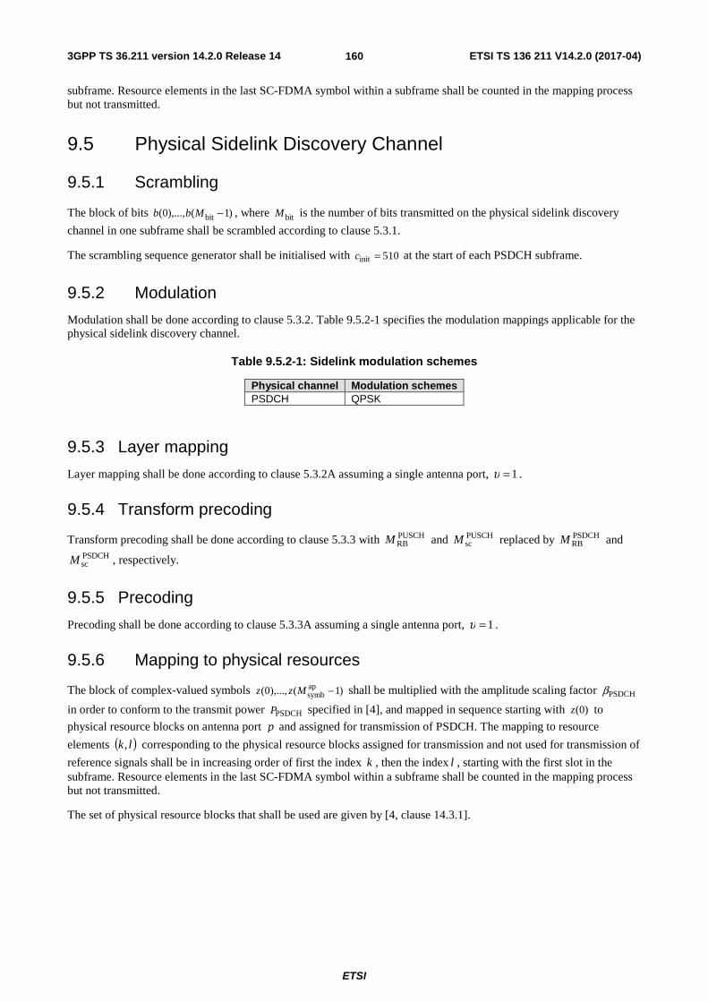
3GPP TS 36.211 version 14.2.0 Release 14 ETSI TS 136 211 V14.2.0 (2017-04)
ETSI
160
subframe. Resource elements in the last SC-FDMA symbol within a subframe shall be counted in the mapping process but not transmitted.
9.5 Physical Sidelink Discovery Channel
9.5.1 Scrambling
The block of bits )1(),...,0( bit −Mbb , where bitM is the number of bits transmitted on the physical sidelink discovery
channel in one subframe shall be scrambled according to clause 5.3.1.
The scrambling sequence generator shall be initialised with 510init =c at the start of each PSDCH subframe.
9.5.2 Modulation
Modulation shall be done according to clause 5.3.2. Table 9.5.2-1 specifies the modulation mappings applicable for the physical sidelink discovery channel.
Table 9.5.2-1: Sidelink modulation schemes
Physical channel Modulation schemes PSDCH QPSK
9.5.3 Layer mapping
Layer mapping shall be done according to clause 5.3.2A assuming a single antenna port, 1=υ .
9.5.4 Transform precoding
Transform precoding shall be done according to clause 5.3.3 with PUSCHRBM and PUSCH
scM replaced by PSDCHRBM and
PSDCHscM , respectively.
9.5.5 Precoding
Precoding shall be done according to clause 5.3.3A assuming a single antenna port, 1=υ .
9.5.6 Mapping to physical resources
The block of complex-valued symbols )1(),...,0( apsymb −Mzz shall be multiplied with the amplitude scaling factor PSDCHβ
in order to conform to the transmit power PSDCHP specified in [4], and mapped in sequence starting with )0(z to
physical resource blocks on antenna port p and assigned for transmission of PSDCH. The mapping to resource
elements ( )lk, corresponding to the physical resource blocks assigned for transmission and not used for transmission of
reference signals shall be in increasing order of first the index k , then the index l , starting with the first slot in the subframe. Resource elements in the last SC-FDMA symbol within a subframe shall be counted in the mapping process but not transmitted.
The set of physical resource blocks that shall be used are given by [4, clause 14.3.1].
3GPP TS 36.211 version 14.2.0 Release 14 ETSI TS 136 211 V14.2.0 (2017-04)
ETSI
161
9.6 Physical Sidelink Broadcast Channel
9.6.1 Scrambling
The block of bits )1(),...,0( bit −Mbb , where bitM is the number of bits transmitted on the physical sidelink broadcast
channel in one subframe, shall be scrambled according to clause 5.3.1. The scrambling sequence generator shall be
initialised at the start of every PSBCH subframe with SLIDinit Nc = .
9.6.2 Modulation
Modulation shall be done according to clause 5.3.2. Table 9.6.2-1 specifies the modulation mappings applicable for the physical sidelink broadcast channel.
Table 9.6.2-1: PSBCH modulation schemes
Physical channel Modulation schemes PSBCH QPSK
9.6.3 Layer mapping
Layer mapping shal be done according to clause 5.3.2A assuming a single antenna port, 1=υ .
9.6.4 Transform precoding
Transform precoding shall be done according to clause 5.3.3 with PUSCHRBM and PUSCH
scM replaced by PSBCHRBM and
PSBCHscM , respectively.
9.6.5 Precoding
Precoding shall be done according to clause 5.3.3A assuming a single antenna port, 1=υ .
9.6.6 Mapping to physical resources
The block of complex-valued symbols )1(),...,0( apsymb −Mzz shall be multiplied with the amplitude scaling factor PSBCHβ
in order to conform to the transmit power PSBCHP specified in [4], and mapped in sequence starting with )0(z to
physical resource blocks on antenna port p . The PSBCH shall use the same set of resource blocks as the
synchronization signal. The mapping to resource elements ( )lk, corresponding to the physical resource blocks used for
the PSBCH and not used for transmission of reference signals or synchronization signals shall be in increasing order of first the index k , then the index l , starting with the first slot in the subframe. The resource-element index k given by
71,...,1,0,2
36RBsc
SLRB =′+−′= k
NNkk
Resource elements in the last SC-FDMA symbol within a subframe should be counted in the mapping process but not transmitted.
9.7 Sidelink Synchronization Signals
A physical-layer sidelink synchronization identity is represented by { }335,...,1,0SLID ∈N , divided into two sets id_net and
id_oon consisting of identities { }167,...,1,0 and { }335,...,169,168 , respectively.

3GPP TS 36.211 version 14.2.0 Release 14 ETSI TS 136 211 V14.2.0 (2017-04)
ETSI
162
9.7.1 Primary sidelink synchronization signal
The primary sidelink synchronization signal is transmitted in two adjacent SC-FDMA symbols in the same subframe.
9.7.1.1 Sequence generation
Each of the two sequences 2,1),61(),...,0( =idd ii used for the primary sidelink synchronization signal in the two SC-
FDMA symbols is given by clause 6.11.1.1 with root index 26=u if 167SLID ≤N and 37=u otherwise.
9.7.1.2 Mapping to resource elements
The sequence ( )ndi shall be multiplied with the amplitude scaling factor PSBCH6272 β⋅ and mapped to resource
elements on antenna port 1020 in the first slot in the subframe according to
( )
⎩⎨⎧
=
+−=
==
prefix cyclic extended1,0
prefix cyclic normal2,12
31
61,...,0 ,
RBsc
SLRB
,
l
NNnk
nnda ilk
9.7.2 Secondary sidelink synchronization signal
The secondary sidelink synchronization signal is transmitted in two adjacent SC-FDMA symbols in the same subframe.
9.7.2.1 Sequence generation
Each of the two sequences 2,1),61(),...,0( =idd ii used for the secondary sidelink synchronization signal is given by
clause 6.11.2.1 assuming
- subframe 0 with 168modSLID
(1)ID NN = and ⎣ ⎦168SL
ID(2)ID NN = for transmission modes 1 and 2, and
- subframe 5 for transmission modes 3 and 4.
9.7.2.2 Mapping to resource elements
The sequence ( )ndi shall be multiplied with the amplitude scaling factor SSSSβ in order to conform to the transmit
power specified in clause 14.4 in 3GPP TS 36.213 [4] and mapped to resource elements on antenna port 1020 in the second slot in the subframe according to
( )
⎩⎨⎧
=
+−=
==
prefix cyclic extended4,3
prefix cyclic normal5,42
31
61,...,0 ,
RBsc
SLRB
,
l
NNnk
nnda ilk
9.8 Demodulation reference signals Demodulation reference signals associated with PSSCH, PSCCH, PSDCH, and PSBCH transmission shall be transmitted according to PUSCH in clause 5.5.2.1 with the following exceptions:
- The parameters in Tables 9.8-1, 9.8-2, and 9.8-3 shall be used.
- The term PUSCH shall be replaced by PSSCH, PSCCH, PSDCH or PSBCH, depending on the physical channel to which the reference signal is associated.

3GPP TS 36.211 version 14.2.0 Release 14 ETSI TS 136 211 V14.2.0 (2017-04)
ETSI
163
- Antenna ports are given by Table 9.2-1.
- The set of physical resource blocks used in the mapping process shall be identical to the corresponding PSSCH/PSCCH/PSDCH/PSBCH transmission.
- The index k in the mapping process in clause 5.5.2.1.2 corresponding to the case where higher-layer parameter ul-DMRS-IFDMA is not set shall be identical to that for the corresponding PSSCH/PSCCH/PSDCH/PSBCH transmission.
- For sidelink transmission modes 3 and 4 on the PSSCH and PSCCH, the mapping shall use 2=l and 5=l for the first slot in the subframe and 1=l and 4=l for the second slot in the subframe.
- For sidelink transmission modes 3 and 4 on the PSBCH, the mapping shall use 4=l and 6=l for the first slot in the subframe and 2=l for the second slot in the subframe.
- For sidelink transmission modes 1 and 2, the pseudo-random sequence generator in clause 5.5.1.3 shall be
initialized at the start of each slot fulfilling 0PSSCHss =n . For sidelink transmission modes 3 and 4 the pseudo-
random sequence generator in clause 5.5.1.3 shall be initialized at the start of each slot fulfilling
02modPSSCHss =n .
- For sidelink transmission modes 3 and 4 on the PSCCH, the cyclic shift λ,csn to be applied for all DM-RS in a
subframe shall be chosen according to clause 14.2.1 of [4].
- For sidelink transmission modes 1and 2 and sidelink discovery, the quantity m in clause 5.5.2.1.1 takes the values 1,0=m and for sidelink transmission modes 3and 4, the quantity m in clause 5.5.2.1.1 takes the values
3,2,1,0=m for PSSCH and 2,1,0=m for PSBCH.
- For sidelink transmission modes 3 and 4, the quantity XIDn equals the decimal representation of CRC on the
PSCCH transmitted in the same subframe as the PSSCH according to ∑−
=−−⋅=
1
0
1XID 2
L
i
iLipn with p and L
given by clause 5.1.1 in [3].
Table 9.8-1: Reference signal parameters for PSSCH.
Parameter in clause 5.5.2.1 PSSCH
Sidelink transmission modes 1 and 2
Sidelink transmission modes 3 and 4
Group hopping
enabled enabled RSIDn SA
IDn XIDn
sn PSSCHssn
PSSCHss2n first DM-RS symbol in a slot
12 PSSCHss +n second DM-RS symbol in a slot
ssf 30modSAIDn ⎣ ⎦ 30mod16X
IDn
Sequence hopping disabled disabled
Cyclic shift λ,csn ⎣ ⎦ 8mod2SAIDn ⎣ ⎦ 8mod2X
IDn
Orthogonal sequence [ ])(⋅λw [ ][ ] 12mod if11
02mod if11SAID
SAID
=−+=++
n
n
[ ][ ] 12mod if1111
02mod if1111XID
XID
=−+−+=++++
n
n
Reference signal length
RSscM PSSCH
scM PSSCHscM
Number of layers υ 1 1 Number of antenna ports P 1 1

3GPP TS 36.211 version 14.2.0 Release 14 ETSI TS 136 211 V14.2.0 (2017-04)
ETSI
164
Table 9.8-2: Reference signal parameters for PSCCH.
Parameter in clause 5.5.2.1 PSCCH
Sidelink transmission modes 1 and 2
Sidelink transmission modes 3 and 4
Group hopping
disabled disabled RSIDn - -
sn - -
ssf 0 8
Sequence hopping disabled disabled
Cyclic shift λ,csn 0 {0, 3, 6, 9}
Orthogonal sequence [ ])(⋅λw [ ]11 ++ [ ]1111 ++++
Reference signal length RSscM PSCCH
scM PSCCHscM
Number of layers υ 1 1 Number of antenna ports P 1 1
Table 9.8-3: Reference signal parameters for PSDCH and PSBCH.
Parameter in clause 5.5.2.1 PSDCH PSBCH
Sidelink transmission modes 1 and 2
Sidelink transmission modes 3 and 4
Group hopping disabled disabled disabled
ssf 0 ⎣ ⎦ 30mod16SLIDN ⎣ ⎦ 30mod16SL
IDN Sequence hopping disabled disabled disabled
Cyclic shift λ,csn 0 ⎣ ⎦ 8mod2SLIDN ⎣ ⎦ 8mod2SL
IDN
(Orthogonal) sequence [ ]LL )(mwλ
[ ]11 ++
[ ][ ] 12mod if11
02mod if11SLID
SLID
=−+=++
N
N
[ ][ ] 12mod if111
02mod if111SLID
SLID
=+−+=+++
N
N
Reference signal length
RSscM PSDCH
scM PSBCHscM PSBCH
scM
Number of layers υ 1 1 1 Number of antenna ports P 1 1 1
9.9 SC-FDMA baseband signal generation
The time-continuous signal ( )ts pl
)( for antenna port p in SC-FDMA symbol l in a sidelink slot is defined by clause
5.6 with ULRBN replaced by SL
RBN .
The cyclic prefix length for each sidelink channel or signal may differ from that configured for uplink transmissions.
9.10 Timing Transmission of a sidelink radio frame number i from the UE shall start soffsetTA SL TA, )( TNN ⋅+ seconds before the
start of the corresponding timing reference frame at the UE. The UE is not required to receive sidelink or downlink transmissions earlier than s624T after the end of a sidelink transmission.
For PSDCH transmission and sidelink synchronization signal transmission for PSDCH:
if the UE has a serving cell fulfilling the S criterion according to [10, clause 5.2.3.2]
- the timing of reference radio frame i equals that of downlink radio frame i of the cell c as given in Subclause 14.3.1 of [4] and

3GPP TS 36.211 version 14.2.0 Release 14 ETSI TS 136 211 V14.2.0 (2017-04)
ETSI
165
- offsetTA N is given by clause 8.1,
otherwise
- the timing of reference radio frame i is implicitly obtained from [4] and
- 0offsetTA =N .
For all other sidelink transmissions:
if the UE has a serving cell fulfilling the S criterion according to [10, clause 5.2.3.2]
- the timing of reference radio frame i equals that of downlink radio frame i in the cell with the same uplink carrier frequency as the sidelink and
- offsetTA N is given by clause 8.1,
otherwise
- the timing of reference radio frame i is implicitly obtained from [4] and
- 0offsetTA =N .
( ) seconds soffsetTA SLTA, TNN ⋅+
Figure 9.9-1: Sidelink timing relation.
The quantity SLTA,N differs between channels and signals according to
⎩⎨⎧
=casesother allfor 0
1 moden ransmissiosidelink tin PSSCHfor TASL TA,
NN
10 Narrowband IoT
10.1 Uplink
10.1.1 Overview
10.1.1.1 Physical channels
The following narrowband physical channels are defined:
- Narrowband Physical Uplink Shared Channel, NPUSCH
- Narrowband Physical Random Access Channel, NPRACH
10.1.1.2 Physical signals
The following uplink narrowband physical signals are defined:

3GPP TS 36.211 version 14.2.0 Release 14 ETSI TS 136 211 V14.2.0 (2017-04)
ETSI
166
- Narrowband demodulation reference signal
10.1.2 Slot structure and physical resources
10.1.2.1 Resource grid
A transmitted physical channel or signal in a slot is described by one or several resource grids of ULscN subcarriers and
ULsymbN SC-FDMA symbols. The resource grid is illustrated in Figure 10.1.2.1-1. The slot number within a radio frame
is denoted sn where { }19,...,1,0s ∈n for kHz 15=Δf and { }4,...,1,0s ∈n for kHz 75.3=Δf .
SC-FDMA symbols
One uplink slot
subc
arri
ers
Resource element
Figure 10.1.2.1-1: Uplink resource grid for NB-IoT
The uplink bandwidth in terms of subcarriers ULscN , and the slot duration slotT are given in Table 10.1.2.1-1.
Table 10.1.2.1-1: NB-IoT parameters.
Subcarrier spacing
ULscN slotT
kHz 75.3=Δf 48 s61440 T⋅
kHz 15=Δf 12 s15360 T⋅
A single antenna port 0=p is used for all uplink transmissions.
10.1.2.2 Resource elements
Each element in the resource grid is called a resource element and is uniquely defined by the index pair ( )lk, in a slot
where 1,...,0 ULsc −= Nk and 1,...,0 UL
symb −= Nl are the indices in the frequency and time domains, respectively.
Resource element ( )lk, corresponds to the complex value lka , . Quantities lka , corresponding to resource elements not
used for transmission of a physical channel or a physical signal in a slot shall be set to zero.
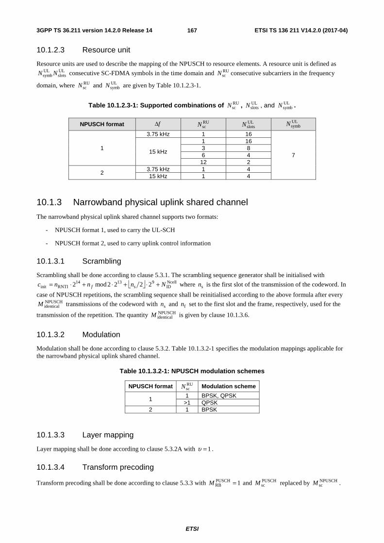
3GPP TS 36.211 version 14.2.0 Release 14 ETSI TS 136 211 V14.2.0 (2017-04)
ETSI
167
10.1.2.3 Resource unit
Resource units are used to describe the mapping of the NPUSCH to resource elements. A resource unit is defined as ULslots
ULsymb NN consecutive SC-FDMA symbols in the time domain and RU
scN consecutive subcarriers in the frequency
domain, where RUscN and UL
symbN are given by Table 10.1.2.3-1.
Table 10.1.2.3-1: Supported combinations of RUscN , UL
slotsN , and ULsymbN .
NPUSCH format fΔ RUscN UL
slotsN ULsymbN
1
3.75 kHz 1 16
7 15 kHz
1 16 3 8 6 4
12 2
2 3.75 kHz 1 4 15 kHz 1 4
10.1.3 Narrowband physical uplink shared channel
The narrowband physical uplink shared channel supports two formats:
- NPUSCH format 1, used to carry the UL-SCH
- NPUSCH format 2, used to carry uplink control information
10.1.3.1 Scrambling
Scrambling shall be done according to clause 5.3.1. The scrambling sequence generator shall be initialised with
⎣ ⎦NcellID
9s
1314RNTIinit 2222mod2 Nnnnc f +⋅+⋅+⋅= where sn is the first slot of the transmission of the codeword. In
case of NPUSCH repetitions, the scrambling sequence shall be reinitialised according to the above formula after every NPUSCHidenticalM transmissions of the codeword with sn and fn set to the first slot and the frame, respectively, used for the
transmission of the repetition. The quantity NPUSCHidenticalM is given by clause 10.1.3.6.
10.1.3.2 Modulation
Modulation shall be done according to clause 5.3.2. Table 10.1.3.2-1 specifies the modulation mappings applicable for the narrowband physical uplink shared channel.
Table 10.1.3.2-1: NPUSCH modulation schemes
NPUSCH format RUscN Modulation scheme
1 1 BPSK, QPSK
>1 QPSK 2 1 BPSK
10.1.3.3 Layer mapping
Layer mapping shall be done according to clause 5.3.2A with 1=υ .
10.1.3.4 Transform precoding
Transform precoding shall be done according to clause 5.3.3 with 1PUSCHRB =M and PUSCH
scM replaced by NPUSCHscM .
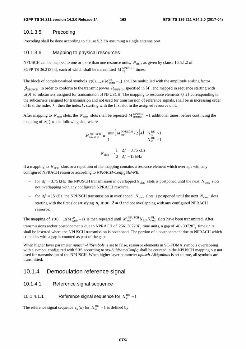
3GPP TS 36.211 version 14.2.0 Release 14 ETSI TS 136 211 V14.2.0 (2017-04)
ETSI
168
10.1.3.5 Precoding
Precoding shall be done according to clause 5.3.3A assuming a single antenna port.
10.1.3.6 Mapping to physical resources
NPUSCH can be mapped to one or more than one resource units, RUN , as given by clause 16.5.1.2 of
3GPP TS 36.213 [4], each of which shall be transmitted NPUSCHrepM times.
The block of complex-valued symbols )1(),...,0( apsymb −Mzz shall be multiplied with the amplitude scaling factor
NPUSCHβ in order to conform to the transmit power NPUSCHP specified in [4], and mapped in sequence starting with
)0(z to subcarriers assigned for transmission of NPUSCH. The mapping to resource elements ( )lk, corresponding to
the subcarriers assigned for transmission and not used for transmission of reference signals, shall be in increasing order of first the index k , then the index l , starting with the first slot in the assigned resource unit.
After mapping to slotsN slots, the slotsN slots shall be repeated 1NPUSCHidentical −M additional times, before continuing the
mapping of )(⋅z to the following slot, where
⎡ ⎤( )⎪⎩
⎪⎨⎧
=>
=11
14,2/minRUsc
RUsc
NPUSCHrepNPUSCH
identicalN
NMM
⎩⎨⎧
=Δ=Δ
=kHz 152
kHz 75.31slots f
fN
If a mapping to slotsN slots or a repetition of the mapping contains a resource element which overlaps with any
configured NPRACH resource according to NPRACH-ConfigSIB-NB,
- for kHz 75.3=Δf the NPUSCH transmission in overlapped slotsN slots is postponed until the next slotsN slots
not overlapping with any configured NPRACH resource.
- for kHz 15=Δf the NPUSCH transmission in overlapped slotsN slots is postponed until the next slotsN slots
starting with the first slot satisfying 02 mod s =n and not overlapping with any configured NPRACH
resource.
The mapping of )1(),...,0( apsymb −Mzz is then repeated until UL
slotsRUNPUSCHrep NNM slots have been transmitted. After
transmissions and/or postponements due to NPRACH of s30720256 T⋅ time units, a gap of s3072040 T⋅ time units
shall be inserted where the NPUSCH transmission is postponed. The portion of a postponement due to NPRACH which coincides with a gap is counted as part of the gap.
When higher layer parameter npusch-AllSymbols is set to false, resource elements in SC-FDMA symbols overlapping with a symbol configured with SRS according to srs-SubframeConfig shall be counted in the NPUSCH mapping but not used for transmission of the NPUSCH. When higher layer parameter npusch-AllSymbols is set to true, all symbols are transmitted.
10.1.4 Demodulation reference signal
10.1.4.1 Reference signal sequence
10.1.4.1.1 Reference signal sequence for 1RUsc =N
The reference signal sequence )(nru for 1RUsc =N is defined by
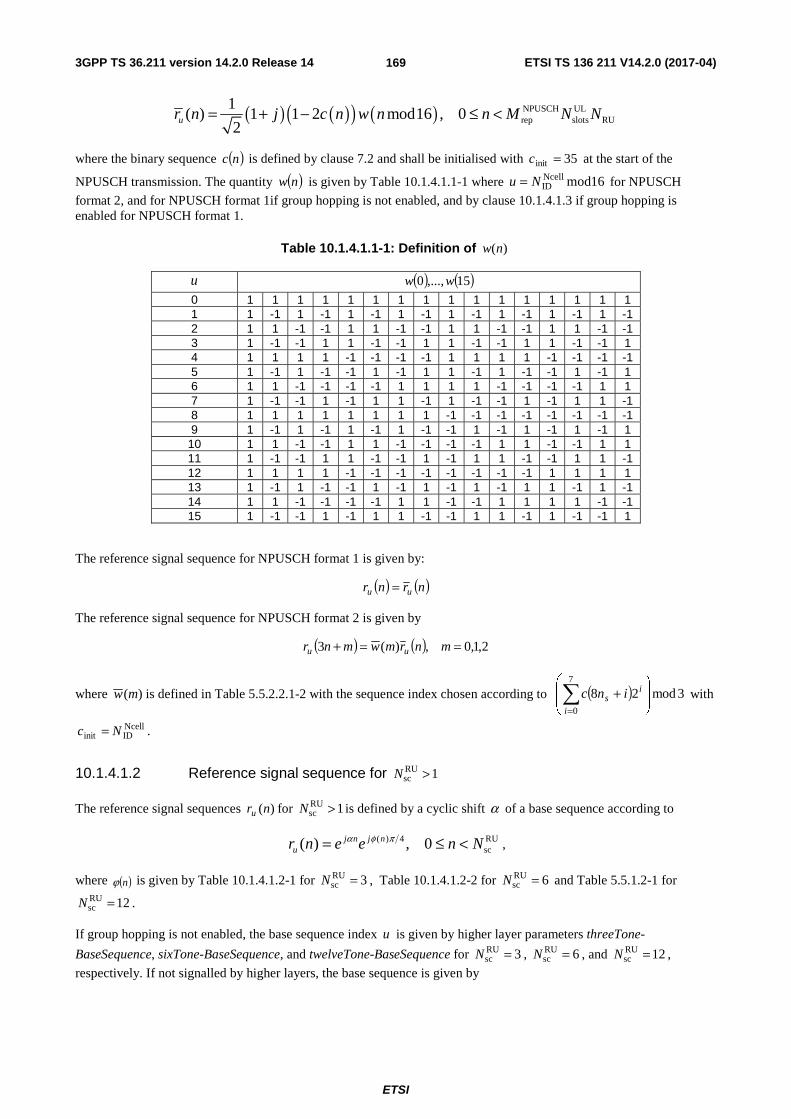
3GPP TS 36.211 version 14.2.0 Release 14 ETSI TS 136 211 V14.2.0 (2017-04)
ETSI
169
( ) ( )( ) ( ) NPUSCH ULrep slots RU
1( ) 1 1 2 mod16 , 0
2ur n j c n w n n M N N= + − ≤ <
where the binary sequence ( )nc is defined by clause 7.2 and shall be initialised with 35init =c at the start of the
NPUSCH transmission. The quantity ( )nw is given by Table 10.1.4.1.1-1 where 16modNcellIDNu = for NPUSCH
format 2, and for NPUSCH format 1if group hopping is not enabled, and by clause 10.1.4.1.3 if group hopping is enabled for NPUSCH format 1.
Table 10.1.4.1.1-1: Definition of )(nw
u ( ) ( )15,...,0 ww
0 1 1 1 1 1 1 1 1 1 1 1 1 1 1 1 1 1 1 -1 1 -1 1 -1 1 -1 1 -1 1 -1 1 -1 1 -1 2 1 1 -1 -1 1 1 -1 -1 1 1 -1 -1 1 1 -1 -1 3 1 -1 -1 1 1 -1 -1 1 1 -1 -1 1 1 -1 -1 1 4 1 1 1 1 -1 -1 -1 -1 1 1 1 1 -1 -1 -1 -1 5 1 -1 1 -1 -1 1 -1 1 1 -1 1 -1 -1 1 -1 1 6 1 1 -1 -1 -1 -1 1 1 1 1 -1 -1 -1 -1 1 1 7 1 -1 -1 1 -1 1 1 -1 1 -1 -1 1 -1 1 1 -1 8 1 1 1 1 1 1 1 1 -1 -1 -1 -1 -1 -1 -1 -1 9 1 -1 1 -1 1 -1 1 -1 -1 1 -1 1 -1 1 -1 1
10 1 1 -1 -1 1 1 -1 -1 -1 -1 1 1 -1 -1 1 1 11 1 -1 -1 1 1 -1 -1 1 -1 1 1 -1 -1 1 1 -1 12 1 1 1 1 -1 -1 -1 -1 -1 -1 -1 -1 1 1 1 1 13 1 -1 1 -1 -1 1 -1 1 -1 1 -1 1 1 -1 1 -1 14 1 1 -1 -1 -1 -1 1 1 -1 -1 1 1 1 1 -1 -1 15 1 -1 -1 1 -1 1 1 -1 -1 1 1 -1 1 -1 -1 1
The reference signal sequence for NPUSCH format 1 is given by:
( ) ( )nrnr uu =
The reference signal sequence for NPUSCH format 2 is given by
( ) ( ) 2,1,0,)(3 ==+ mnrmwmnr uu
where )(mw is defined in Table 5.5.2.2.1-2 with the sequence index chosen according to ( ) 3mod287
0⎟⎟
⎠
⎞
⎜⎜
⎝
⎛+∑
=i
is inc with
NcellIDinit Nc = .
10.1.4.1.2 Reference signal sequence for 1RUsc >N
The reference signal sequences )(nru for 1RUsc >N is defined by a cyclic shift α of a base sequence according to
( ) 4 RUsc( ) , 0j n j n
ur n e e n Nα φ π= ≤ < ,
where ( )nϕ is given by Table 10.1.4.1.2-1 for 3RUsc =N , Table 10.1.4.1.2-2 for 6RU
sc =N and Table 5.5.1.2-1 for
12RUsc =N .
If group hopping is not enabled, the base sequence index u is given by higher layer parameters threeTone-
BaseSequence, sixTone-BaseSequence, and twelveTone-BaseSequence for 3RUsc =N , 6RU
sc =N , and 12RUsc =N ,
respectively. If not signalled by higher layers, the base sequence is given by
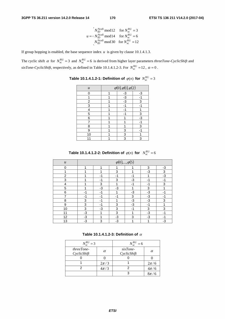
3GPP TS 36.211 version 14.2.0 Release 14 ETSI TS 136 211 V14.2.0 (2017-04)
ETSI
170
⎪⎩
⎪⎨
⎧
===
=12for 30mod
6for 14mod
3for 12mod
RUsc
NcellID
RUsc
NcellID
RUsc
NcellID
NN
NN
NN
u
If group hopping is enabled, the base sequence index u is given by clause 10.1.4.1.3.
The cyclic shift α for 3RUsc =N and 6RU
sc =N is derived from higher layer parameters threeTone-CyclicShift and
sixTone-CyclicShift, respectively, as defined in Table 10.1.4.1.2-3. For 12RUsc =N , 0=α .
Table 10.1.4.1.2-1: Definition of )(nϕ for 3RUsc =N
u ( ) ( ) ( )2,1,0 ϕϕϕ
0 1 -3 -3 1 1 -3 -1 2 1 -3 3 3 1 -1 -1 4 1 -1 1 5 1 -1 3 6 1 1 -3 7 1 1 -1 8 1 1 3 9 1 3 -1 10 1 3 1 11 1 3 3
Table 10.1.4.1.2-2: Definition of )(nϕ for 6RUsc =N
u ( ) ( )5,...,0 ϕϕ
0 1 1 1 1 3 -3 1 1 1 3 1 -3 3 2 1 -1 -1 -1 1 -3 3 1 -1 3 -3 -1 -1 4 1 3 1 -1 -1 3 5 1 -3 -3 1 3 1 6 -1 -1 1 -3 -3 -1 7 -1 -1 -1 3 -3 -1 8 3 -1 1 -3 -3 3 9 3 -1 3 -3 -1 1
10 3 -3 3 -1 3 3 11 -3 1 3 1 -3 -1 12 -3 1 -3 3 -3 -1 13 -3 3 -3 1 1 -3
Table 10.1.4.1.2-3: Definition of α
3RUsc =N 6RU
sc =N
threeTone-CyclicShift
α sixTone-CyclicShift
α
0 0 0 0 1 3/2π 1 6/2π 2 3/4π 2 6/4π 3 6/8π

3GPP TS 36.211 version 14.2.0 Release 14 ETSI TS 136 211 V14.2.0 (2017-04)
ETSI
171
10.1.4.1.3 Group hopping
For the reference signal for NPUSCH format 1, sequence-group hopping can be enabled where the sequence-group number u in slot sn is defined by a group hopping pattern )( sgh nf and a sequence-shift pattern ssf according to
( ) RUseqsssgh mod)( Nfnfu +=
where the number of reference signal sequences available for each resource unit size, RUseqN is given by Table 10.1.4.1.3-
1.
Table 10.1.4.1.3-1: Definition of RUseqN
RUscN
RUseqN
1 16 3 12 6 14 12 30
Sequence-group hopping can be enabled or disabled by means of the cell-specific parameter groupHoppingEnabled provided by higher layers. Sequence-group hopping for NPUSCH can be disabled for a certain UE through the higher-layer parameter groupHoppingDisabled despite being enabled on a cell basis unless the NPUSCH transmission corresponds to a Random Access Response Grant or a retransmission of the same transport block as part of the contention based random access procedure.
The group-hopping pattern )( sgh nf is given by
RUseq
7
0 ssgh mod2)8()( Nincnfi
i⎟⎠⎞
⎜⎝⎛ ⋅+′= ∑ =
where ss nn =′ for 1RUsc >N and sn′ is the slot number of the first slot of the resource unit for 1RU
sc =N . The pseudo-
random sequence )(ic is defined by clause 7.2. The pseudo-random sequence generator shall be initialized with
⎥⎥
⎦
⎥
⎢⎢
⎣
⎢=
RUseq
NcellID
initN
Nc at the beginning of the resource unit for 1RU
sc =N and in every even slot for 1RUsc >N .
The sequence-shift pattern ssf is given by
( ) RUseqss
NcellIDss mod NNf Δ+=
where { }29,...,1,0ss ∈Δ is given by higher-layer parameter groupAssignmentNPUSCH. If no value is signalled , 0ss =Δ .
10.1.4.2 Mapping to physical resources
The sequence ( )⋅r shall be multiplied with the amplitude scaling factor NPUSCHβ and mapped in sequence starting with
( )0r to the sub-carriers.
The set of sub-carriers used in the mapping process shall be identical to the corresponding NPUSCH transmission as defined in clause 10.1.3.6. The mapping to resource elements ),( lk shall be in increasing order of first k , then l , and finally the slot number. The
values of the symbol index l in a slot are given in Table 10.1.4.2-1.
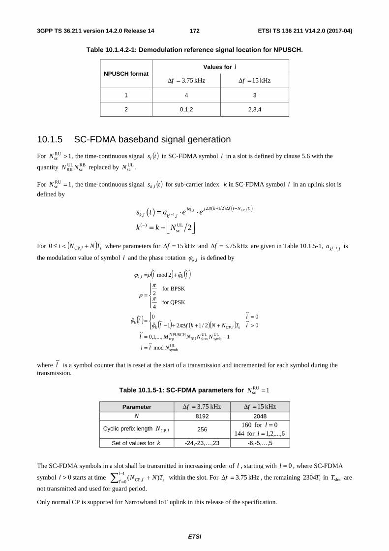
3GPP TS 36.211 version 14.2.0 Release 14 ETSI TS 136 211 V14.2.0 (2017-04)
ETSI
172
Table 10.1.4.2-1: Demodulation reference signal location for NPUSCH.
NPUSCH format Values for l
kHz 75.3=Δf kHz 15=Δf
1 4 3
2 0,1,2 2,3,4
10.1.5 SC-FDMA baseband signal generation
For 1RUsc >N , the time-continuous signal ( )tsl in SC-FDMA symbol l in a slot is defined by clause 5.6 with the
quantity RBsc
ULRB NN replaced by UL
scN .
For 1RUsc =N , the time-continuous signal ( )ts lk , for sub-carrier index k in SC-FDMA symbol l in an uplink slot is
defined by
( ) ( ) ( )CP, s,( )
2 1 2
, ,
( ) ULsc 2
lk l j k f t N Tjk l k l
s t a e e
k k N
πφ−
+ Δ −
−
= ⋅ ⋅
⎢ ⎥= + ⎣ ⎦
For ( ) s,CP0 TNNt l +<≤ where parameters for kHz 15=Δf and kHz 75.3=Δf are given in Table 10.1.5-1, lk
a,)(− is
the modulation value of symbol l and the phase rotation lk ,ϕ is defined by
( ) ( )
( ) ( ) ( )( )
ULsymb
ULsymb
ULslotsRU
NPUSCHrep
s,
,
mod~
1,...,1,0~
0~
2/121~
ˆ
0~
0~ˆ
QPSKfor 4
BPSKfor 2
~ˆ2mod
~
Nll
NNNMl
lTNNkfl
ll
ll
lCPkk
klk
=
−=
⎪⎩
⎪⎨⎧
>++Δ+−=
=
⎪⎩
⎪⎨
⎧
=
+=
πϕϕ
π
π
ρ
ϕρϕ
where l~
is a symbol counter that is reset at the start of a transmission and incremented for each symbol during the transmission.
Table 10.1.5-1: SC-FDMA parameters for 1RUsc =N
Parameter kHz 75.3=Δf kHz 15=Δf
N 8192 2048
Cyclic prefix length lN ,CP 256 0for 160 =l
6,...,2,1for 144 =l
Set of values for k -24,-23,…,23 -6,-5,…,5
The SC-FDMA symbols in a slot shall be transmitted in increasing order of l , starting with 0=l , where SC-FDMA
symbol 0>l starts at time ∑−
=′ ′ +1
0 s,CP )(l
l l TNN within the slot. For kHz 75.3=Δf , the remaining s2304T in slotT are
not transmitted and used for guard period.
Only normal CP is supported for Narrowband IoT uplink in this release of the specification.
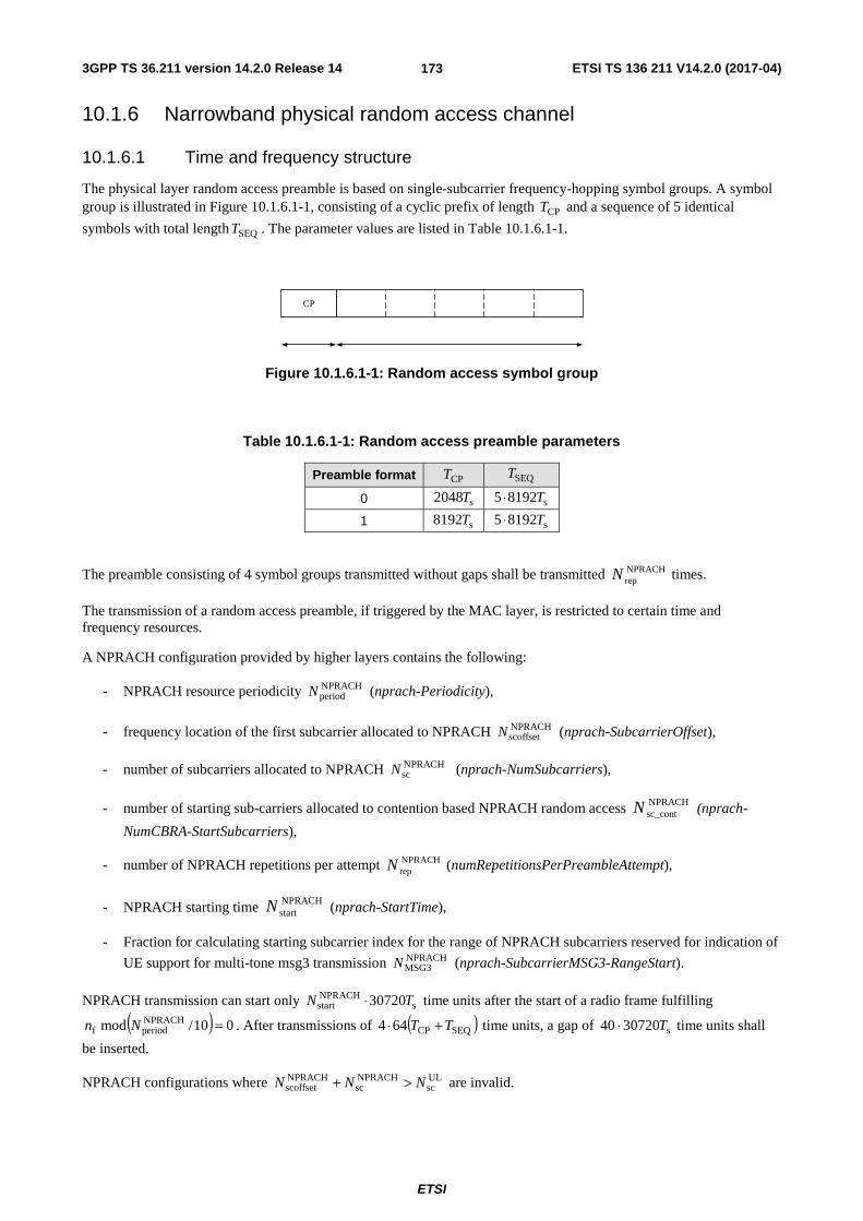
3GPP TS 36.211 version 14.2.0 Release 14 ETSI TS 136 211 V14.2.0 (2017-04)
ETSI
173
10.1.6 Narrowband physical random access channel
10.1.6.1 Time and frequency structure
The physical layer random access preamble is based on single-subcarrier frequency-hopping symbol groups. A symbol group is illustrated in Figure 10.1.6.1-1, consisting of a cyclic prefix of length CPT and a sequence of 5 identical
symbols with total length SEQT . The parameter values are listed in Table 10.1.6.1-1.
CP
Figure 10.1.6.1-1: Random access symbol group
Table 10.1.6.1-1: Random access preamble parameters
Preamble format CPT SEQT
0 s2048T s81925 T⋅
1 s8192T s81925 T⋅
The preamble consisting of 4 symbol groups transmitted without gaps shall be transmitted NPRACHrepN times.
The transmission of a random access preamble, if triggered by the MAC layer, is restricted to certain time and frequency resources.
A NPRACH configuration provided by higher layers contains the following:
- NPRACH resource periodicity NPRACHperiodN (nprach-Periodicity),
- frequency location of the first subcarrier allocated to NPRACH NPRACHscoffsetN (nprach-SubcarrierOffset),
- number of subcarriers allocated to NPRACH NPRACH scN (nprach-NumSubcarriers),
- number of starting sub-carriers allocated to contention based NPRACH random access NPRACHsc_cont N (nprach-
NumCBRA-StartSubcarriers),
- number of NPRACH repetitions per attempt NPRACHrepN (numRepetitionsPerPreambleAttempt),
- NPRACH starting time NPRACHstartN (nprach-StartTime),
- Fraction for calculating starting subcarrier index for the range of NPRACH subcarriers reserved for indication of
UE support for multi-tone msg3 transmission NPRACHMSG3N (nprach-SubcarrierMSG3-RangeStart).
NPRACH transmission can start only sNPRACHstart 30720TN ⋅ time units after the start of a radio frame fulfilling
( ) 010/mod NPRACHperiodf =Nn . After transmissions of ( )SEQCP644 TT +⋅ time units, a gap of s3072040 T⋅ time units shall
be inserted.
NPRACH configurations where ULsc
NPRACHsc
NPRACHscoffset NNN >+ are invalid.

3GPP TS 36.211 version 14.2.0 Release 14 ETSI TS 136 211 V14.2.0 (2017-04)
ETSI
174
The NPRACH starting subcarriers allocated to contention based random access are split in two sets of subcarriers,
{ }1,...,1,0 NPRACHMSG3
NPRACHsc_cont −NN and { }1,..., NPRACH
sc_cont NPRACHMSG3
NPRACHsc_cont −NNN , where the second set, if present, indicate UE
support for multi-tone msg3 transmission.
The frequency location of the NPRACH transmission is constrained within 12RAsc =N sub-carriers. Frequency hopping
shall be used within the 12 subcarriers, where the frequency location of the ith symbol group is given by
( ) )(~RASCstart
RAsc innin += where ⎣ ⎦ RA
scNNnNn ⋅+= RAscinit
NPRACHscoffsetstart and
( )
( ) ( ) ( ) ( )( ) 01
mod11mod21
6)1(~ and 24mod6)1(~6)1(~ and 24mod6)1(~
12mod)1(~ and 3,14mod1)1(~02mod)1(~ and 3,14mod1)1(~
0 and 04modmod)4/()0(~
)(~
RAsc
RAsc
910
110
)110(
RAsc
RAsc
RAsc
RAsc
RAsc
RAsc
RAsc
RAsc
RAsc
RAsc
RAsc
=−
⎟⎟
⎠
⎞
⎜⎜
⎝
⎛+−
⎟⎟
⎠
⎞
⎜⎜
⎝
⎛+−=
⎪⎪⎪
⎩
⎪⎪⎪
⎨
⎧
≥−=−−<−=+−
=−=−−=−=+−
>=+
=
∑+
+=
+−
f
NNnctftf
iniin
iniin
iniin
iniin
iiNifn
in
t
tn
tn
where RAscNnn mod)0(~
initRASC = with initn being the subcarrier selected by the MAC layer from }1,...,1,0{ NPRACH
sc −N ,
and the pseudo random sequence )(nc is given by clause 7.2. The pseudo random sequence generator shall be
initialised with NcellIDinit Nc = .
10.1.6.2 Baseband signal generation
The time-continuous random access signal )(tsi for symbol group i is defined by
( ) ( ) ( )CP0RASC 2/1)(2
NPRACHTtfKkinj
iRAets −Δ++= πβ
Where CPSEQ0 TTt +<≤ , NPRACHβ is an amplitude scaling factor in order to conform to the transmit power
NPRACHP specified in clause 16.3.1 in 3GPP TS 36.213 [4], 2ULsc0 Nk −= , RAffK ΔΔ= accounts for the difference
in subcarrier spacing between the random access preamble and uplink data transmission, and the location in the frequency domain controlled by the parameter )(RA
SC in is derived from clause 10.1.6.1. The variable RAfΔ is given by
Table 10.1.6.2-1.
Table 10.1.6.2-1: Random access baseband parameters
Preamble format RAfΔ
0, 1 3.75 kHz
10.1.7 Modulation and upconversion
Modulation and upconversion to the carrier frequency of the complex-valued baseband signal or the complex-valued NPRACH baseband signal is shown in Figure 5.8-1. The filtering required prior to transmission is defined by the requirements in 3GPP TS 36.101 [7].

3GPP TS 36.211 version 14.2.0 Release 14 ETSI TS 136 211 V14.2.0 (2017-04)
ETSI
175
10.2 Downlink
10.2.1 Overview
10.2.1.1 Physical channels
A downlink narrowband physical channel corresponds to a set of resource elements carrying information originating from higher layers and is the interface defined between 3GPP TS 36.212 [3] and the present document 3GPP TS 36.211.
The following downlink physical channels are defined:
- Narrowband Physical Downlink Shared Channel, NPDSCH
- Narrowband Physical Broadcast Channel, NPBCH
- Narrowband Physical Downlink Control Channel, NPDCCH
10.2.1.2 Physical signals
A downlink narrowband physical signal corresponds to a set of resource elements used by the physical layer but does not carry information originating from higher layers. The following downlink physical signals are defined:
- Narrowband reference signal, NRS
- Narrowband synchronization signal
- Narrowband positioning reference signal, NPRS
10.2.2 Slot structure and physical resource elements
10.2.2.1 Resource grid
The transmitted signal on one antenna port in each slot is described by a resource grid of size one resource block as defined in clause 6.2.3.
Only kHz 15=Δf is supported.
Narrowband positioning reference signals are transmitted on antenna port 2006=p . The channel over which a symbol
on antenna port 2006=p is conveyed can be inferred from the channel over which another symbol on the same
antenna port is conveyed only within M consecutive subframes where
- if the higher layer parameter nprsBitmap is configured , M equals the length of the nprsBitmap;
- if the higher layer parameter nprsBitmap is not configured, NPRSNM = where NPRSN is configured by higher
layers.
10.2.2.2 Resource elements
Resource elements are defined according to clause 6.2.2.
10.2.2.3 Guard period for half-duplex FDD operation
Only type-B half-duplex FDD operation is supported.
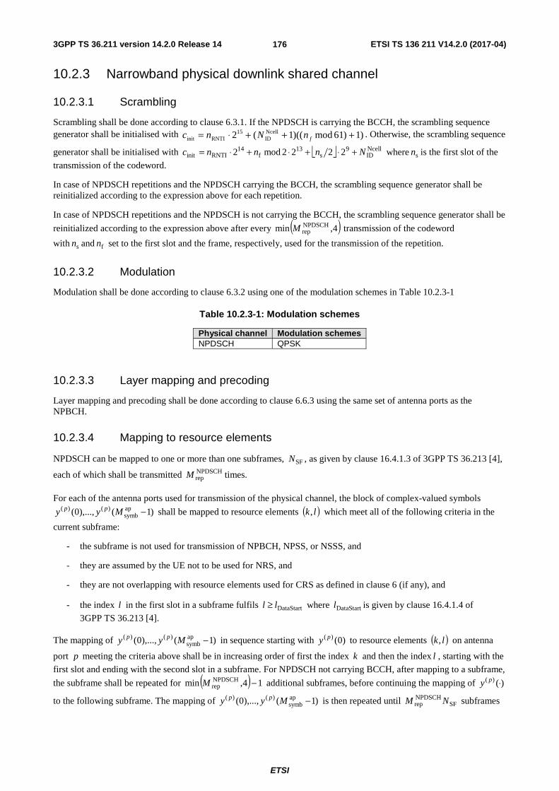
3GPP TS 36.211 version 14.2.0 Release 14 ETSI TS 136 211 V14.2.0 (2017-04)
ETSI
176
10.2.3 Narrowband physical downlink shared channel
10.2.3.1 Scrambling
Scrambling shall be done according to clause 6.3.1. If the NPDSCH is carrying the BCCH, the scrambling sequence generator shall be initialised with )1)61mod)((1(2 Ncell
ID15
RNTIinit +++⋅= fnNnc . Otherwise, the scrambling sequence
generator shall be initialised with ⎣ ⎦ NcellID
9s
13f
14RNTIinit 2222mod2 Nnnnc +⋅+⋅+⋅= where sn is the first slot of the
transmission of the codeword.
In case of NPDSCH repetitions and the NPDSCH carrying the BCCH, the scrambling sequence generator shall be reinitialized according to the expression above for each repetition.
In case of NPDSCH repetitions and the NPDSCH is not carrying the BCCH, the scrambling sequence generator shall be
reinitialized according to the expression above after every ( )4,min NPDSCHrepM transmission of the codeword
with sn and fn set to the first slot and the frame, respectively, used for the transmission of the repetition.
10.2.3.2 Modulation
Modulation shall be done according to clause 6.3.2 using one of the modulation schemes in Table 10.2.3-1
Table 10.2.3-1: Modulation schemes
Physical channel Modulation schemes NPDSCH QPSK
10.2.3.3 Layer mapping and precoding
Layer mapping and precoding shall be done according to clause 6.6.3 using the same set of antenna ports as the NPBCH.
10.2.3.4 Mapping to resource elements
NPDSCH can be mapped to one or more than one subframes, SFN , as given by clause 16.4.1.3 of 3GPP TS 36.213 [4],
each of which shall be transmitted NPDSCHrepM times.
For each of the antenna ports used for transmission of the physical channel, the block of complex-valued symbols
)1(),...,0( apsymb
)()( −Myy pp shall be mapped to resource elements ( )lk, which meet all of the following criteria in the
current subframe:
- the subframe is not used for transmission of NPBCH, NPSS, or NSSS, and
- they are assumed by the UE not to be used for NRS, and
- they are not overlapping with resource elements used for CRS as defined in clause 6 (if any), and
- the index l in the first slot in a subframe fulfils DataStartll ≥ where DataStartl is given by clause 16.4.1.4 of
3GPP TS 36.213 [4].
The mapping of )1(),...,0( apsymb
)()( −Myy pp in sequence starting with )0()( py to resource elements ( )lk, on antenna
port p meeting the criteria above shall be in increasing order of first the index k and then the index l , starting with the
first slot and ending with the second slot in a subframe. For NPDSCH not carrying BCCH, after mapping to a subframe,
the subframe shall be repeated for ( ) 14,min NPDSCHrep −M additional subframes, before continuing the mapping of )()( ⋅py
to the following subframe. The mapping of )1(),...,0( apsymb
)()( −Myy pp is then repeated until SFNPDSCHrep NM subframes

3GPP TS 36.211 version 14.2.0 Release 14 ETSI TS 136 211 V14.2.0 (2017-04)
ETSI
177
have been transmitted. For NPDSCH carrying BCCH, the )1(),...,0( apsymb
)()( −Myy pp is mapped to SFN subframes in
sequence and then repeated until SFNPDSCHrep NM subframes have been transmitted.
The NPDSCH transmission can be configured by higher layers with transmission gaps where the NPSDCH transmission is postponed. There are no gaps in the NPDSCH transmission if thresholdgap,max NR < where thresholdgap,N is
given by the higher layer parameter dl-GapThreshold and maxR is given by [4]. The gap starting frame and subframe is
given by ⎣ ⎦( ) 0mod210 periodgap,sf =+ Nnn where the gap periodicity, periodgap,N , is given by the higher layer parameter
dl-GapPeriodicity. The gap duration in number of subframes is given by periodgap,coeff gap,durationgap, NNN = , where
coeff gap,N is given by the higher layer parameter dl-GapDurationCoeff. For NPDSCH carrying the BCCH there are no
gaps in the transmission.
The UE shall not expect NPDSCH in subframe i if it is not a NB-IoT downlink subframe, except for transmissions of NPDSCH carrying SystemInformationBlockType1-NB in subframe 4. In case of NPDSCH transmissions, in subframes that are not NB-IoT downlink subframes, the NPDSCH transmission is postponed until the next NB-IoT downlink subframe.
10.2.4 Narrowband physical broadcast channel
10.2.4.1 Scrambling
Scrambling shall be done according to clause 6.6.1 with bitM denoting the number of bits to be transmitted on the
NPBCH. bitM equals 1600 for normal cyclic prefix. The scrambling sequence shall be initialised with NcellIDinit Nc = in
radio frames fulfilling 064modf =n .
10.2.4.2 Modulation
Modulation shall be done according to clause 6.6.2 using the modulation scheme in Table 10.2.4.2-1
Table 10.2.4.2-1: Modulation schemes for NPBCH
Physical channel Modulation schemes NPBCH QPSK
10.2.4.3 Layer mapping and precoding
Layer mapping and precoding shall be done according to clause 6.6.3 with { }2,1∈P . The UE shall assume antenna
ports 2000 and 2001 are used for the transmission of the narrowband physical broadcast channel.
10.2.4.4 Mapping to resource elements
The block of complex-valued symbols )1(),...,0( symb)()( −Myy pp for each antenna port is transmitted in subframe 0
during 64 consecutive radio frames starting in each radio frame fulfilling 064modf =n . 800symb =M for normal
cyclic prefix. Define )1(),...,0( )()( −Kyy pf
pf as the block of complex-valued symbols to be transmitted in subframe 0 of
radio frame 64modfnf = , as ⎣ ⎦ )8/()()( )()( ifKyiiy pf
pf +=θ , 99,...,0=i with 100=K for normal cyclic prefix,
and
⎪⎪
⎩
⎪⎪
⎨
⎧
=+=−=+==+=−
=+=
=
1)12( and 1)2( if ,
0)12( and 1)2( if ,
1)12( and 0)2( if ,1
0)12( and 0)2( if ,1
)(
icicj
icicj
icic
icic
i
ff
ff
ff
ff
fθ
3GPP TS 36.211 version 14.2.0 Release 14 ETSI TS 136 211 V14.2.0 (2017-04)
ETSI
178
where the scrambling sequence )( jc f , 199,...,0=j is given by clause 7.2, and shall be initialized at the start of each
radio frame with NcellID
93NcellIDinit 21) 8 mod )(1( NnNc f +⋅++= . The block of complex-valued symbols
)1(),...,0( )()( −Kyy pf
pf shall be mapped in sequence starting with )0()( p
fy to resource elements ( )lk, . The mapping to
resource elements ( )lk, not reserved for transmission of reference signals shall be in increasing order of first the
index k , then the index l . The first three OFDM symbols in a subframe shall not be used in the mapping process.
For the purpose of the mapping, the UE shall assume cell-specific reference signals for antenna ports 0-3 and narrowband reference signals for antenna ports 2000 and 2001 being present irrespective of the actual configuration.
The frequency shift of the cell-specific reference signals shall be calculated by replacing cellIDN with Ncell
IDN in the
calculation of shiftv in clause 6.10.1.2.
10.2.5 Narrowband physical downlink control channel
10.2.5.1 NPDCCH formats
The narrowband physical downlink control channel carries control information. A narrowband physical control channel is transmitted on an aggregation of one or two consecutive narrowband control channel elements (NCCEs), where a narrowband control channel element corresponds to 6 consecutive subcarriers in a subframe where NCCE 0 occupies subcarriers 0 through 5 and NCCE 1 occupies subcarriers 6 through 11. The NPDCCH supports multiple formats as listed in Table 10.2.5.1-1. For NPDCCH format 1, both NCCEs belong to the same subframe.
One or two NPDCCHs can be transmitted in a subframe.
Table 10.2.5.1-1: Supported NPDCCH formats
NPDCCH format Number of NCCEs 0 1 1 2
10.2.5.2 Scrambling
Scrambling shall be done according to clause 6.8.2. The scrambling sequence shall be initialised at the start of subframe
k0 according to [4] Subclause 16.6 and after every 4th NPDCCH subframe with ⎣ ⎦ NcellID
9sinit 22 Nnc += where sn is the
first slot of the NPDCCH subframe in which scrambling is (re-)initialized.
10.2.5.3 Modulation
Modulation shall be done according to clause 6.8.3 using the modulation scheme in Table 10.2.5.3-1
Table 10.2.5.3-1: Modulation schemes
Physical channel Modulation schemes NPDCCH QPSK
10.2.5.4 Layer mapping and precoding
Layer mapping and precoding shall be done according to clause 6.6.3 using the same set of antenna ports as the NPBCH.
10.2.5.5 Mapping to resource elements
The block of complex-valued symbols )1(),...,0( symb −Myy shall be mapped in sequence starting with )0(y to
resource elements ( )lk, on the associated antenna port which meet all of the following criteria:

3GPP TS 36.211 version 14.2.0 Release 14 ETSI TS 136 211 V14.2.0 (2017-04)
ETSI
179
- they are part of the NCCE(s) assigned for the NPDCCH transmission, and
- they are not used for transmission of NPBCH, NPSS, or NSSS , and
- they are assumed by the UE not to be used for NRS, and
- they are not overlapping with resource elements used for PBCH, PSS, SSS, or CRS as defined in clause 6 (if any), and
- the index l in the first slot in a subframe fulfils tNPDCCHStarll ≥ where tNPDCCHStarl is given by clause 16.6.1 of
3GPP TS 36.213 [4].
The mapping to resource elements ( )lk, on antenna port p meeting the criteria above shall be in increasing order of
first the index k and then the index l , starting with the first slot and ending with the second slot in a subframe.
The NPDCCH transmission can be configured by higher layers with transmissions gaps where the NPDCCH transmission is postponed. The configuration is the same as described for NPDSCH in clause 10.2.3.4.
The UE shall not expect NPDCCH in subframe i if it is not a NB-IoT downlink subframe. In case of NPDCCH transmissions, in subframes that are not NB-IoT downlink subframes, the NPDCCH transmission is postponed until the next NB-IoT downlink subframe.
10.2.6 Narrowband reference signal (NRS)
Before a UE obtains operationModeInfo:
- The UE may assume narrowband reference signals (NRSs) are transmitted in subframes #0 and #4 and in subframes #9 not containing NSSS.
On an NB-IoT carrier for which a UE receives higher-layer parameter operationModeInfo indicating guardband or standalone.
- Before the UE obtains SystemInformationBlockType1-NB, the UE may assume narrowband reference signals are transmitted in subframes #0, #1, #3, #4 and in subframes #9 not containing NSSS.
- After the UE obtains SystemInformationBlockType1-NB, the UE may assume narrowband reference signals are transmitted in subframes #0, #1, #3, #4, subframes #9 not containing NSSS, and in NB-IoT downlink subframes.
On an NB-IoT carrier for which DL-CarrierConfigCommon-NB is present and no inbandCarrierInfo is present.
- When an NB-IoT UE is configured by higher layers to decode NPDCCH with CRC scrambled by the P-RNTI, the UE may assume NRSs are transmitted in the NPDCCH candidate where the UE finds a DCI with CRC scrambled by the P-RNTI. The UE may also assume NRSs are transmitted 10 NB-IoT DL subframes before and 4 NB-IoT DL subframes after the NPDCCH candidate where the UE finds a DCI with CRC scrambled by the P-RNTI. If the DCI with CRC scrambled by the P-RNTI schedules a NPDSCH, the UE may assume NRSs are transmitted in the NB-IoT DL subframes carrying the NPDSCH and 4 subframes after the NPDSCH.
- During random access procedure, during the window controlled by higher layers where the UE shall attempt to decode the NPDCCH with DCI scrambled by RA-RNTI (see [8], subclause 5.1.4), before the DCI scrambled by RA-RNTI is detected, the UE may assume NRSs are transmitted in the Type-2 CSS configured by higher layers, as well as 10 NB-IoT DL subframes before and 4 NB-IoT DL subframes after each Type-2 CSS. If a DCI scrambled by the RA-RNTI is detected, the UE may assume NRSs are transmitted in the NPDSCH scheduled by the DCI scrambled by the RA-RNTI, as well as 4 NB-IoT DL subframes before and after the scheduled NPDSCH. In addition, when the UE attempts to decode a DCI with CRC scrambled by the RA-RNTI as well as receiving the NPDSCH scheduled by the DCI scrambled by the RA-RNTI, the UE may assume NRSs are transmitted in subframes #0, #1, #3, #4 and #9.
- During random access procedure, when an NB-IoT UE is configured by higher layers to decode NPDCCH with CRC scrambled by the temporary C-RNTI and/or the C-RNTI, before the the DCI scrambled by temporary C-RNTI and/or C-RNTI is detected, the UE may assume NRSs are transmitted in the Type-2 CSS configured by higher layers, as well as 10 NB-IoT DL subframes before the start of each Type-2 CSS and 4 NB-IoT DL subframes after the end of each Type-2 CSS until the mac-ContentionResolutionTimer expires. If a DCI scrambled by the temporary C-RNTI or C-RNTI is detected, the UE may assume NRSs are transmitted in the

3GPP TS 36.211 version 14.2.0 Release 14 ETSI TS 136 211 V14.2.0 (2017-04)
ETSI
180
NPDSCH scheduled by the DCI scrambled by the temporary C-RNTI or C-RNTI as well as 4 NB-IoT DL subframes before and after the scheduled NPDSCH.
- An NB-IoT UE may assume NRSs are transmitted in NB-IoT DL subframes that are used for Type1A-NPDCCH common search space, and Type2A-NPDCCH common search space, as well as 10 NB-IoT DL subframes prior and 4 NB-IoT DL subframes after each Type1A-NPDCCH common search space and Type2A-NPDCCH common search space. A UE may assume NRSs are transmistted in NB-IoT DL subframes carrying NPDSCH scheduled by DCI CRC scrambled by G-RNTI or SC-RNTI as well as 4 NB-IoT DL subframes prior and after the scheduled NPDSCH.
- In other cases, the UE may assume NRSs are transmitted in subframes #0, #1, #3, #4, #9, and in NB-IoT downlink subframes and shall not expect NRSs in other downlink subframes.
On an NB-IoT carrier for which a UE receives higher-layer parameter operationModeInfo indicating inband-SamePCI or inband-DifferentPCI.
- Before the UE obtains SystemInformationBlockType1-NB, the UE may assume narrowband reference signals are transmitted in subframes #0, #4 and in subframes #9 not containing NSSS.
- After the UE obtains SystemInformationBlockType1-NB, the UE may assume narrowband reference signals are transmitted in subframes #0, #4, subframes #9 not containing NSSS, and in NB-IoT downlink subframes.
On an NB-IoT carrier for which DL-CarrierConfigCommon-NB is present and inbandCarrierInfo is present:
- When an NB-IoT UE is configured by higher layers to decode NPDCCH with CRC scrambled by the P-RNTI, the UE may assume NRSs are transmitted in the NPDCCH candidate where the UE finds a DCI with CRC scrambled by the P-RNTI. The UE may also assume NRSs are transmitted 10 NB-IoT DL subframes before and 4 NB-IoT DL subframes after the NPDCCH candidate. If the DCI with CRC scrambled by the P-RNTI schedules a NPDSCH, the UE may assume NRSs are transmitted in the NB-IoT DL subframes carrying the NPDSCH and 4 subframes after the NPDSCH.
- During random access procedure, during the window controlled by higher layers where the UE shall attempt to decode the NPDCCH with DCI scrambled by RA-RNTI (see [8], subclause 5.1.4), before the DCI scrambled by RA-RNTI is detected, the UE may assume NRSs are transmitted in the Type-2 CSS configured by higher layers, as well as 10 NB-IoT DL subframes before and and 4 NB-IoT DL subframes after the start of each Type-2 CSS. If a DCI scrambled by the RA-RNTI is detected, the UE may assume NRSs are transmitted in the NPDSCH scheduled by the DCI scrambled by the RA-RNTI, as well as 4 NB-IoT DL subframes before and after the scheduled NPDSCH. In addition, when the UE attempts to decod a DCI with CRC scrambled by the RA-RNTI as well as receiving the NPDSCH scheduled by the DCI scrambled by the RA-RNTI, the UE may assume NRSs are transmitted in subframes #0, #4 and #9.
- During random access procedure, when an NB-IoT UE is configured by higher layers to decode NPDCCH with CRC scrambled by the temporary C-RNTI and/or the C-RNTI, before the DCI scrambled by temporary C-RNTI and/or C-RNTI, is detected, the UE may assume NRSs are transmitted in the Type-2 CSS configured by higher layers, as well as 10 NB-IoT DL subframes before the start of each Type-2 CSS and 4 NB-IoT DL subframes after the end of each Type-2 CSS until the mac-ContentionResolutionTimer expires. If a DCI scrambled by the temporary C-RNTI or C-RNTI is detected, the UE may assume NRSs are transmitted in the NPDSCH scheduled by the DCI scrambled by the temporary C-RNTI or C-RNTI as well as 4 NB-IoT DL subframes before and after the scheduled NPDSCH.
- An NB-IoT UE may assume NRSs are transmitted in NB-IoT DL subframes that are used for Type1A-NPDCCH common search space, and Type2A-NPDCCH common search space, as well as 10 NB-IoT DL subframes prior and 4 NB-IoT DL subframes after each Type1A-NPDCCH common search space and Type2A-NPDCCH common search space. A UE may assume NRSs are transmistted in NB-IoT DL subframes carrying NPDSCH scheduled by DCI CRC scrambled by G-RNTI or SC-RNTI as well as 4 NB-IoT DL subframes prior and after the scheduled NPDSCH.
- In other cases, the UE may assume NRSs are transmitted in subframes #0, #4, #9, and in NB-IoT downlink subframes and shall not expect NRSs in other downlink subframes.
An NB-IoT UE may assume NRSs are not transmitted in subframes that are configured by higher layer parameter nprsBitmap for narrowband positioning reference signal transmission.

3GPP TS 36.211 version 14.2.0 Release 14 ETSI TS 136 211 V14.2.0 (2017-04)
ETSI
181
10.2.6.1 Sequence generation
The narrowband reference sequence shall be initialised according to clause 6.10.1.1 where cellIDN is replaced with
NcellIDN .
10.2.6.2 Mapping to resource elements
Narrowband reference signals are transmitted on one or two antenna ports { }2001,2000∈p .
If the higher layer indicates UE may assume that cellIDN is equal to Ncell
IDN , UE may assume
- the number of antenna ports for the cell-specific reference signals as defined in clause 6.10.1 is the same as for the narrowband reference signals,
- the antenna ports for cell-specific reference signals {0, 1} are equivalent to antenna ports for narrowband reference signals {2000, 2001}, respectively, and
- the cell-specific reference signals are available in all subframes where the narrowband reference signals are available.
If the higher layer does not indicate UE may assume that cellIDN is equal to Ncell
IDN , UE may assume
- the number of antenna port for the cell-specific reference signals as defined in clause 6.10.1 is obtained from the higher layer parameter eutra-NumCRS-Ports,
- the cell-specific reference signals are available in all subframes where the narrowband reference signals are available, and
the cell-specific frequency shift for cell-specific reference signals as defined in clause 6.10.1.2 is given by
6modNcellIDshift Nv = .
The reference signal sequence )(s, mr nl shall be mapped to complex-valued modulation symbols )(
,plka used as reference
symbols for antenna port p in slot sn according to
)'(s,
)(, mra nlplk =
where
( )
1
1,0
1,2
6mod6
DLmax,RB
DLsymb
DLsymb
shift
−+=′
=
−−=
++=
Nmm
m
NNl
vvmk
The variables v and shiftv define the position in the frequency domain for the different reference signals where v is
given by
⎪⎪
⎩
⎪⎪
⎨
⎧
−==−==−==−==
=
1 and 2001 if0
2 and 2001 if3
1 and 2000 if3
2 and 2000 if0
DLsymb
DLsymb
DLsymb
DLsymb
Nlp
Nlp
Nlp
Nlp
v
The cell-specific frequency shift is given by 6modNcellIDshift Nv = .
Resource elements ( )lk, used for transmission of narrowband reference signals on any of the antenna ports in a slot
shall not be used for any transmission on any other antenna port in the same slot and set to zero.
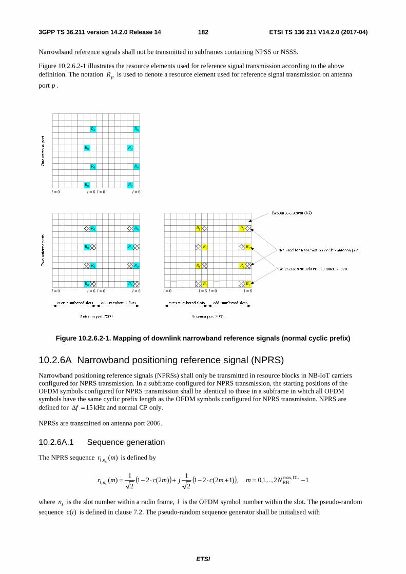
3GPP TS 36.211 version 14.2.0 Release 14 ETSI TS 136 211 V14.2.0 (2017-04)
ETSI
182
Narrowband reference signals shall not be transmitted in subframes containing NPSS or NSSS.
Figure 10.2.6.2-1 illustrates the resource elements used for reference signal transmission according to the above definition. The notation pR is used to denote a resource element used for reference signal transmission on antenna
port p .
1R
0R0R
0R 0R
0=l
0R
0R
0R
6=l 0=l
0R
0R
0R
0R
6=l
One antenna port
Two antenna ports
0=l
0R
0R
6=l 0=l
0R
0R
6=l 0=l
1R
6=l 0=l
1R
6=l
0R
1R
1R
1R
1R
1R
Figure 10.2.6.2-1. Mapping of downlink narrowband reference signals (normal cyclic prefix)
10.2.6A Narrowband positioning reference signal (NPRS)
Narrowband positioning reference signals (NPRSs) shall only be transmitted in resource blocks in NB-IoT carriers configured for NPRS transmission. In a subframe configured for NPRS transmission, the starting positions of the OFDM symbols configured for NPRS transmission shall be identical to those in a subframe in which all OFDM symbols have the same cyclic prefix length as the OFDM symbols configured for NPRS transmission. NPRS are defined for kHz 15=Δf and normal CP only.
NPRSs are transmitted on antenna port 2006.
10.2.6A.1 Sequence generation
The NPRS sequence )(s, mr nl is defined by
( ) ( ) 12,...,1,0 ,)12(212
1)2(21
2
1)( DLmax,
RB, s−=+⋅−+⋅−= Nmmcjmcmr nl
where sn is the slot number within a radio frame, l is the OFDM symbol number within the slot. The pseudo-random
sequence )(ic is defined in clause 7.2. The pseudo-random sequence generator shall be initialised with

3GPP TS 36.211 version 14.2.0 Release 14 ETSI TS 136 211 V14.2.0 (2017-04)
ETSI
183
⎣ ⎦ ( )( ) ( )( ) ( ) CPNPRSID
NPRSIDs
10NPRSID
28init 512mod21512mod211725122 NNNlnNc +⋅++⋅⋅+++⋅⋅+⋅=
at the start of each OFDM symbol where { }4095,...,1,0NPRSID ∈N equals Ncell
IDN unless configured by higher layers and
where .1CP =N
10.2.6A.2 Mapping to resource elements
For an NB-IoT carrier which is configured for NPRS tranmission, the reference signal sequence )(s, mr nl shall be
mapped to complex-valued modulation symbols )(,plka used as reference signal for antenna port p in slot sn according
to
)'(s,
)(, mra nlplk =
where
- when the higher layer parameter when the higher layer parameter operationModeInfoNPRS for the configured NB-IoT carrier is set to in-band
( )
( )( )
nNnmm
m
n
n
n
l
vlmk
~2
1,0
portsantennaPBCH4and12modif6,5,3,2
portsantennaPBCH2or1and12modif6,5,3,2,1
02modif6,5,3
6mod66
DLmax,RB
'PRB
s
s
s
shift
−++=′
=
⎪⎩
⎪⎨
⎧
===
=
+−+=
where 'PRBn is signalled by higher layers nprs-SequenceInfo, and 1~ =n if the higher layer parameter nprs-
SequenceInfo indicates DLRBN is odd, and 0~ =n if the higher layer parameter nprs-SequenceInfo indicates DL
RBN is
even.
- when the higher layer parameter operationModeInfoNPRS for the configured NB-IoT carrier is set to standalone or guard-band
( )
1'
1,0
6,5,4,3,2,1,0
6mod66
DLmax,RB
shift
−+=
==
+−+=
Nmm
m
l
vlmk
and where 6modNPRSIDshift Nv = . If NPRS
IDN is not configured by higher layers, NcellID
NPRSID NN = . The number of PBCH
antenna ports is signalled by higher layers.
If higher layer parameter nprsBitmap is not configured, resource elements in OFDM symbols 5 and 6 in each slot shall not be used for transmission of NPRS.
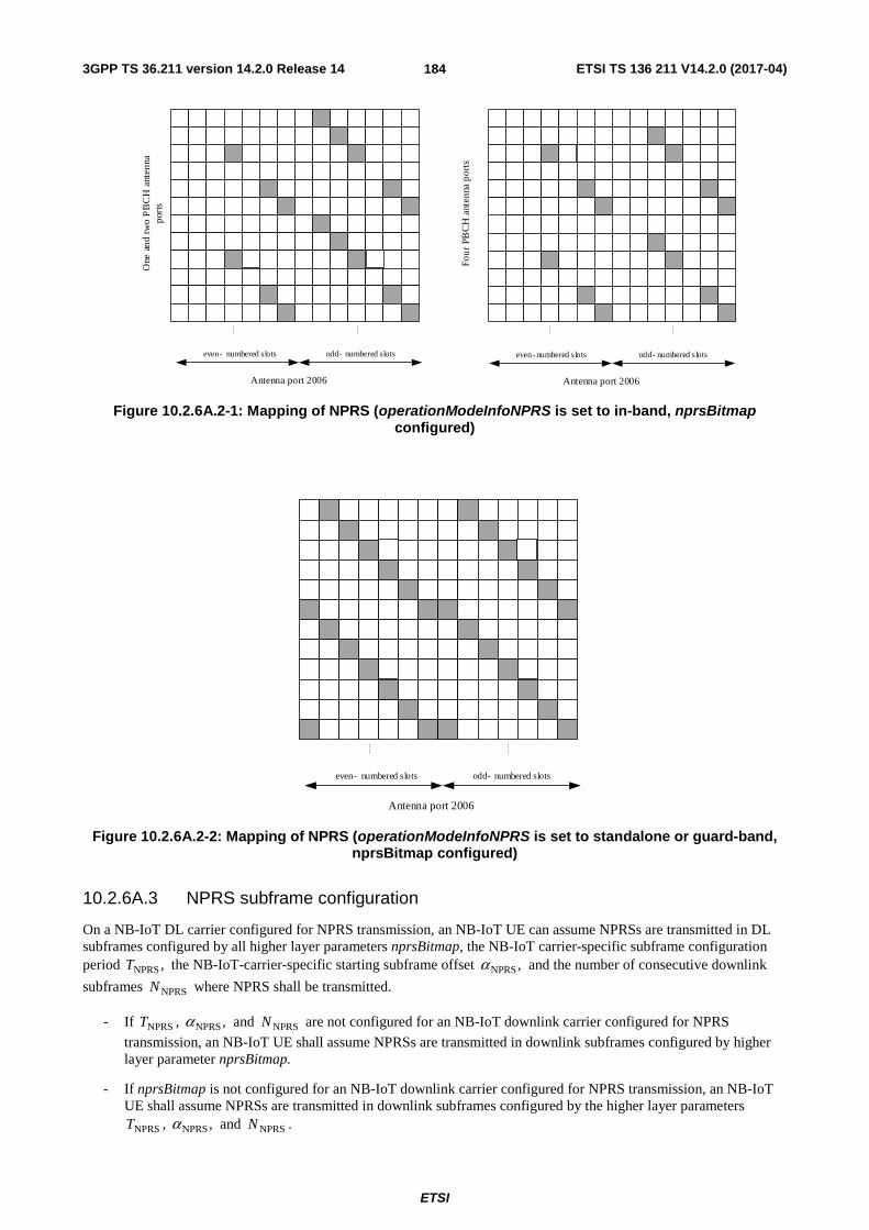
3GPP TS 36.211 version 14.2.0 Release 14 ETSI TS 136 211 V14.2.0 (2017-04)
ETSI
184
Four
PB
CH
ant
enna
por
ts
One
and
two
PB
CH
ant
enna
po
rts
even- numbered slots odd- numbered slots
Antenna port 2006
even-numbered slots odd- numbered slots
Antenna port 2006
Figure 10.2.6A.2-1: Mapping of NPRS (operationModeInfoNPRS is set to in-band, nprsBitmap configured)
even- numbered slots odd- numbered slots
Antenna port 2006
Figure 10.2.6A.2-2: Mapping of NPRS (operationModeInfoNPRS is set to standalone or guard-band, nprsBitmap configured)
10.2.6A.3 NPRS subframe configuration
On a NB-IoT DL carrier configured for NPRS transmission, an NB-IoT UE can assume NPRSs are transmitted in DL subframes configured by all higher layer parameters nprsBitmap, the NB-IoT carrier-specific subframe configuration period ,NPRST the NB-IoT-carrier-specific starting subframe offset ,NPRSα and the number of consecutive downlink
subframes NPRSN where NPRS shall be transmitted.
- If NPRST , ,NPRSα and NPRSN are not configured for an NB-IoT downlink carrier configured for NPRS
transmission, an NB-IoT UE shall assume NPRSs are transmitted in downlink subframes configured by higher layer parameter nprsBitmap.
- If nprsBitmap is not configured for an NB-IoT downlink carrier configured for NPRS transmission, an NB-IoT UE shall assume NPRSs are transmitted in downlink subframes configured by the higher layer parameters
NPRST , ,NPRSα and NPRSN .
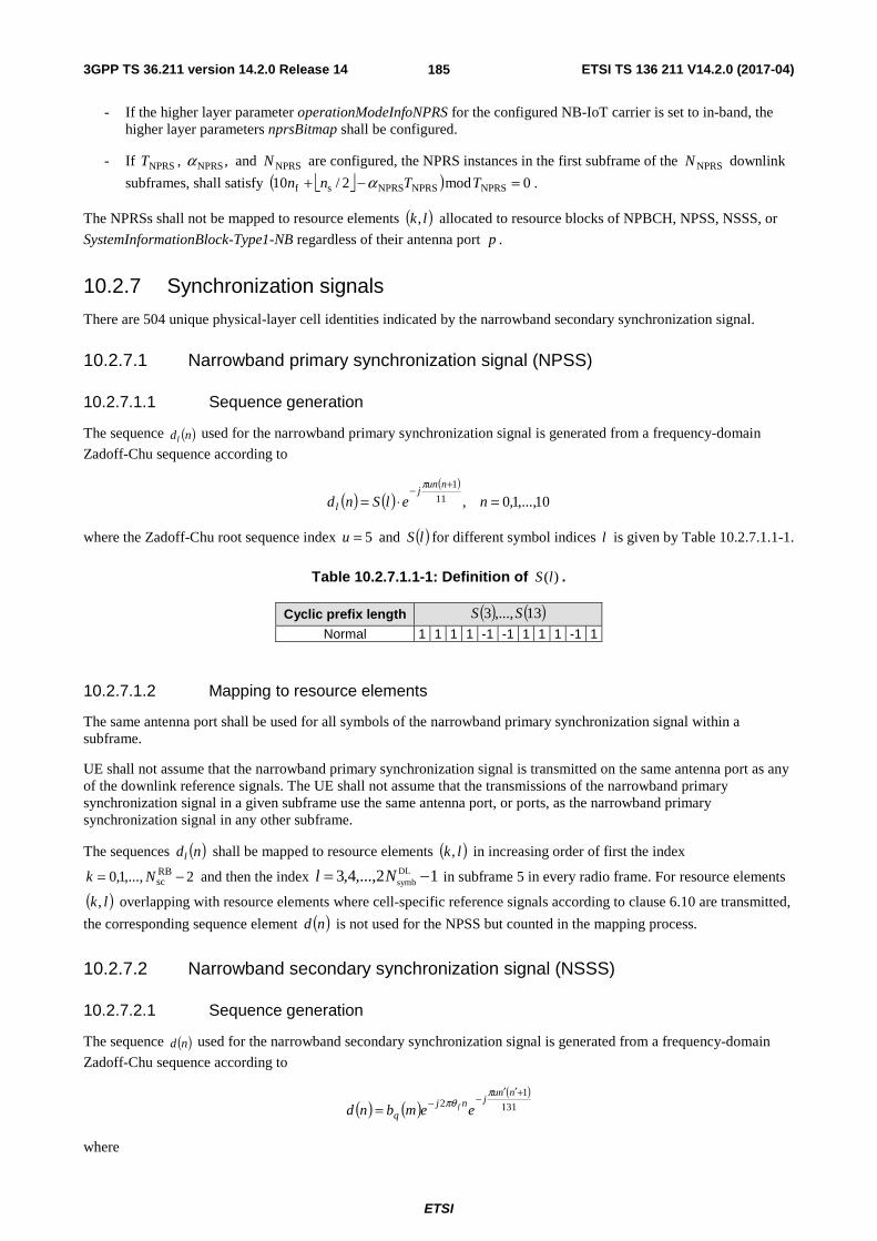
3GPP TS 36.211 version 14.2.0 Release 14 ETSI TS 136 211 V14.2.0 (2017-04)
ETSI
185
- If the higher layer parameter operationModeInfoNPRS for the configured NB-IoT carrier is set to in-band, the higher layer parameters nprsBitmap shall be configured.
- If NPRST , ,NPRSα and NPRSN are configured, the NPRS instances in the first subframe of the NPRSN downlink
subframes, shall satisfy ⎣ ⎦( ) 0mod2/10 NPRSNPRSNPRSsf =−+ TTnn α .
The NPRSs shall not be mapped to resource elements ( )lk, allocated to resource blocks of NPBCH, NPSS, NSSS, or
SystemInformationBlock-Type1-NB regardless of their antenna port p .
10.2.7 Synchronization signals
There are 504 unique physical-layer cell identities indicated by the narrowband secondary synchronization signal.
10.2.7.1 Narrowband primary synchronization signal (NPSS)
10.2.7.1.1 Sequence generation
The sequence ( )ndl used for the narrowband primary synchronization signal is generated from a frequency-domain
Zadoff-Chu sequence according to
( ) ( )( )
10,...,1,0,11
1
=⋅=+−
nelSndnun
j
l
π
where the Zadoff-Chu root sequence index 5=u and ( )lS for different symbol indices l is given by Table 10.2.7.1.1-1.
Table 10.2.7.1.1-1: Definition of )(lS .
Cyclic prefix length ( ) ( )13,...,3 SS
Normal 1 1 1 1 -1 -1 1 1 1 -1 1
10.2.7.1.2 Mapping to resource elements
The same antenna port shall be used for all symbols of the narrowband primary synchronization signal within a subframe.
UE shall not assume that the narrowband primary synchronization signal is transmitted on the same antenna port as any of the downlink reference signals. The UE shall not assume that the transmissions of the narrowband primary synchronization signal in a given subframe use the same antenna port, or ports, as the narrowband primary synchronization signal in any other subframe.
The sequences ( )ndl shall be mapped to resource elements ( )lk, in increasing order of first the index
2,...,1,0 RBsc −= Nk and then the index 12,...,4,3 DL
symb −= Nl in subframe 5 in every radio frame. For resource elements
( )lk, overlapping with resource elements where cell-specific reference signals according to clause 6.10 are transmitted,
the corresponding sequence element ( )nd is not used for the NPSS but counted in the mapping process.
10.2.7.2 Narrowband secondary synchronization signal (NSSS)
10.2.7.2.1 Sequence generation
The sequence ( )nd used for the narrowband secondary synchronization signal is generated from a frequency-domain
Zadoff-Chu sequence according to
( ) ( )( )
131
12
+′′−−=
nnujnj
q eembnd f
ππθ
where

3GPP TS 36.211 version 14.2.0 Release 14 ETSI TS 136 211 V14.2.0 (2017-04)
ETSI
186
⎥⎥⎦
⎥
⎢⎢⎣
⎢=
+=
==′=
126
3126mod
128mod
131mod
131,...,1,0
NcellID
NcellID
Nq
Nu
nm
nn
n
The binary sequence ( )mbq is given by Table 10.2.7.2.1-1. The cyclic shift fθ in frame number fn is given by
( ) 4mod2/132
33ff n=θ .
Table 10.2.7.2.1-1: Definition of ( )mbq .
q ( ) ( )127,...,0 qq bb
0 [1 1 1 1 1 1 1 1 1 1 1 1 1 1 1 1 1 1 1 1 1 1 1 1 1 1 1 1 1 1 1 1 1 1 1 1 1 1 1 1 1 1 1 1 1 1 1 1 1 1 1 1 1 1 1 1 1 1 1 1 1 1 1 1 1 1 1 1 1 1 1 1 1 1 1 1 1 1 1 1 1 1 1 1 1 1 1 1 1 1 1 1 1 1 1 1 1 1 1 1 1 1 1 1 1 1 1 1 1 1 1 1 1 1 1 1 1 1 1 1 1 1 1 1 1 1 1 1]
1
[1 -1 -1 1 -1 1 1 -1 -1 1 1 -1 1 -1 -1 1 -1 1 1 -1 1 -1 -1 1 1 -1 -1 1 -1 1 1 -1 1 -1 -1 1 -1 1 1 -1 -1 1 1 -1 1 -1 -1 1 -1 1 1 -1 1 -1 -1 1 1 -1 -1 1 -1 1 1 -1 1 -1 -1 1 -1 1 1 -1 -1 1 1 -1 1 -1 -1 1 -1 1 1 -1 1 -1 -1 1 1 -1 -1 1 -1 1 1 -1 1 -1 -1 1 -1 1 1 -1 -1 1 1 -1 1 -1 -1 1 -1 1 1 -1 1 -1 -1 1 1 -1 -1 1 -1 1 1 -1]
2
[1 -1 -1 1 -1 1 1 -1 -1 1 1 -1 1 -1 -1 1 -1 1 1 -1 1 -1 -1 1 1 -1 -1 1 -1 1 1 -1 -1 1 1 -1 1 -1 -1 1 1 -1 -1 1 -1 1 1 -1 1 -1 -1 1 -1 1 1 -1 -1 1 1 -1 1 -1 -1 1 1 -1 -1 1 -1 1 1 -1 -1 1 1 -1 1 -1 -1 1 -1 1 1 -1 1 -1 -1 1 1 -1 -1 1 -1 1 1 -1 -1 1 1 -1 1 -1 -1 1 1 -1 -1 1 -1 1 1 -1 1 -1 -1 1 -1 1 1 -1 -1 1 1 -1 1 -1 -1 1]
3
[1 -1 -1 1 -1 1 1 -1 -1 1 1 -1 1 -1 -1 1 -1 1 1 -1 1 -1 -1 1 1 -1 -1 1 -1 1 1 -1 -1 1 1 -1 1 -1 -1 1 1 -1 -1 1 -1 1 1 -1 1 -1 -1 1 -1 1 1 -1 -1 1 1 -1 1 -1 -1 1 -1 1 1 -1 1 -1 -1 1 1 -1 -1 1 -1 1 1 -1 1 -1 -1 1 -1 1 1 -1 -1 1 1 -1 1 -1 -1 1 1 -1 -1 1 -1 1 1 -1 -1 1 1 -1 1 -1 -1 1 -1 1 1 -1 1 -1 -1 1 1 -1 -1 1 -1 1 1 -1]
10.2.7.2.2 Mapping to resource elements
The same antenna port shall be used for all symbols of the narrowband secondary synchronization signal within a subframe.
UE shall not assume that the narrowband secondary synchronization signal is transmitted on the same antenna port as any of the downlink reference signals. The UE shall not assume that the transmissions of the narrowband secondary synchronization signal in a given subframe use the same antenna port, or ports, as the narrowband secondary synchronization signal in any other subframe.
The sequence ( )nd shall be mapped to resource elements ( )lk, in sequence starting with )0(d in increasing order of
first the index k over the 12 assigned subcarriers and then the index l over the assigned last NSSSsymbN symbols of
subframe 9 in radio frames fulfilling 02modf =n , where NSSSsymbN is given by Table 10.2.7.2.2-1.
Table 10.2.7.2.2-1: NSSS number of symbols
Cyclic prefix length NSSSsymbN
Normal 11
For resource elements ( )lk, overlapping with resource elements where cell-specific reference signals according to
clause 6.10 are transmitted, the corresponding sequence element ( )nd is not used for the NSSS but counted in the
mapping process.

3GPP TS 36.211 version 14.2.0 Release 14 ETSI TS 136 211 V14.2.0 (2017-04)
ETSI
187
10.2.8 OFDM baseband signal generation
For an NB-IoT carrier
- for which the higher layer parameter operationModeInfo indicates ‘inband-DifferentPCI’ and for all NB-IoT downlink physical channels and signals except NPRS,
- for which the higher layer parameter operationModeInfo indicates ‘Guardband’ or ‘Standalone’,
- for an NB-IoT carrier for which the higher layer parameter CarrierConfigDedicated-NB is present and no inbandCarrierInfo is present, or
- for an NB-IoT carrier for which the higher layer parameters CarrierConfigDedicated-NB and inbandCarrierInfo
are present and the higher layers do not indicate NcellIDN is the same as cell
IDN and for all NB-IoT downlink
physical channels and signals except NPRS,
the time-continuous signal ( )ts pl
)( on antenna port p in OFDM symbol l in a downlink slot is defined by
( ) ( )
⎣ ⎦
⎡ ⎤∑
−
−=
−Δ+⋅= −
12/
2/
)2/1(2)(,
)(
RBsc
RBsc
s,CP)(
N
Nk
TNtfkjplk
pl
leats π
for ( ) s,CP0 TNNt l ×+<≤ where ⎣ ⎦2)( RBscNkk +=− , 2048=N , kHz 15=Δf and )(
,plka is the content of resource
element ( )lk, on antenna port p .
Otherwise, the time-continuous signal ( )ts pl
)(' on antenna port p in OFDM symbol 'l , where
}27,...,0{)4mod(' DLsymb ∈+= snNll is the OFDM symbol index from the start of the last even-numbered subframe, is
defined by
( )⎣ ⎦
⎡ ⎤
∑∑=
⎟⎟⎠
⎞⎜⎜⎝
⎛−Δ−
−=
⎟⎟⎠
⎞⎜⎜⎝
⎛−Δ
⋅+⋅= +
+
−
−2/
1
2)(
',
1
2/
2)(
',
)('
RBsc
DLRB sDL
symbmod',CP
)(',)(
RBsc
DLRB
sDLsymbmod',CP
)(',)(
NN
k
TNtfkjp
lkNNk
TNtfkjp
lk
pl
Nllk
Nllk eaeeaets
πθπθ
for ( ) s,CP0 TNNt l ×+<≤ where ⎣ ⎦2RBsc
DLRB
)( NNkk +=− and ⎣ ⎦ 12RBsc
DLRB
)( −+=+ NNkk ,
⎟⎟
⎠
⎞
⎜⎜
⎝
⎛+= ∑
=−
'
07mod,', '2
l
iiCPsIoTNBlk NNlTfj πθ if resource element )',( lk is used for Narrowband IoT except for NPRS, and
0 otherwise including NPRS. The quantity IoTNBf − is the frequency location of the center of the Narrowband IoT PRB
minus the frequency location of the center of the LTE signal.
Only normal CP is supported for Narrowband IoT downlink in this release of the specification.
10.2.9 Modulation and upconversion
Modulation and upconversion to the carrier frequency of the complex-valued OFDM baseband signal for each antenna port is shown in Figure 6.13-1. The filtering required prior to transmission is defined by the requirements in 3GPP TS 36.104 [6].

3GPP TS 36.211 version 14.2.0 Release 14 ETSI TS 136 211 V14.2.0 (2017-04)
ETSI
188
Annex A (informative): Change history
Change history Date TSG # TSG Doc. CR Rev Subject/Comment Old New 2006-09-24 - - - Draft version created - 0.0.0 2006-10-09 - - - Updated skeleton 0.0.0 0.0.1 2006-10-13 - - - Endorsed by RAN1 0.0.1 0.1.0 2006-10-23 - - - Inclusion of decision from RAN1#46bis 0.1.0 0.1.1 2006-11-06 - - - Updated editor’s version 0.1.1 0.1.2 2006-11-09 - - - Updated editor’s version 0.1.2 0.1.3 2006-11-10 - - - Endorsed by RAN1#47 0.1.3 0.2.0 2006-11-27 - - - Editor’s version, including decisions from RAN1#47 0.2.0 0.2.1 2006-12-14 - - - Updated editor’s version 0.2.1 0.2.2 2007-01-15 - - - Updated editor’s version 0.2.2 0.2.3 2007-01-19 - - - Endorsed by RAN1#47bis 0.2.3 0.3.0 2007-02-01 - - - Editor’s version, including decisions from RAN1#47bis 0.3.0 0.3.1 2007-02-12 - - - Updated editor’s version 0.3.1 0.3.2 2007-02-16 - - - Endorsed by RAN1#48 0.3.2 0.4.0 2007-02-16 - - - Editor’s version, including decisions from RAN1#48 0.4.0 0.4.1 2007-02-21 - - - Updated editor’s version 0.4.1 0.4.2 2007-03-03 RP_35 RP-070169 For information at RAN#35 0.4.2 1.0.0
2007-04-25 - - - Editor’s version, including decisions from RAN1#48bis and RAN1 TDD Ad Hoc 1.0.0 1.0.1
2007-05-03 - - - - Updated editor’s version 1.0.1 1.0.2 2007-05-08 - - - - Updated editor’s version 1.0.2 1.0.3 2007-05-11 - - - - Updated editor’s version 1.0.3 1.0.4 2007-05-11 - - - - Endorsed by RAN1#49 1.0.4 1.1.0 2007-05-15 - - - - Editor’s version, including decisions from RAN1#49 1.1.0 1.1.1 2007-06-05 - - - - Updated editor’s version 1.1.1 1.1.2 2007-06-25 - - - - Endorsed by RAN1#49bis 1.1.2 1.2.0 2007-07-10 - - - - Editor’s version, including decisions from RAN1#49bis 1.2.0 1.2.1 2007-08-10 - - - - Updated editor’s version 1.2.1 1.2.2 2007-08-20 - - - - Updated editor’s version 1.2.2 1.2.3 2007-08-24 - - - - Endorsed by RAN1#50 1.2.3 1.3.0 2007-08-27 - - - - Editor’s version, including decisions from RAN1#50 1.3.0 1.3.1 2007-09-05 - - - - Updated editor’s version 1.3.1 1.3.2 2007-09-08 RP_37 RP-070729 - - For approval at RAN#37 1.3.2 2.0.0
12/09/07 RP_37 RP-070729 Approved version 2.0.0 8.0.0 28/11/07 RP_38 RP-070949 0001 - Introduction of optimized FS2 for TDD 8.0.0 8.1.0
28/11/07 RP_38 RP-070949 0002 - Introduction of scrambling sequences, uplink reference signal sequences, secondary synchronization sequences and control channel processing
8.0.0 8.1.0
05/03/08 RP_39 RP-080219 0003 1 Update of uplink reference-signal hopping, downlink reference signals, scrambling sequences, DwPTS/UpPTS lengths for TDD and control channel processing
8.1.0 8.2.0
28/05/08 RP_40 RP-080432 0004 - Correction of the number of subcarriers in PUSCH transform precoding
8.2.0 8.3.0
28/05/08 RP_40 RP-080432 0005 - Correction of PHICH mapping 8.2.0 8.3.0 28/05/08 RP_40 RP-080432 0006 - Correction of PUCCH resource index for PUCCH format 2 8.2.0 8.3.0 28/05/08 RP_40 RP-080432 0007 3 Correction of the predefined hopping pattern for PUSCH 8.2.0 8.3.0 28/05/08 RP_40 RP-080432 0008 - Non-binary hashing functions 8.2.0 8.3.0 28/05/08 RP_40 RP-080432 0009 1 PUCCH format 1 8.2.0 8.3.0 28/05/08 RP_40 RP-080432 0010 1 CR on Uplink DM RS hopping 8.2.0 8.3.0
28/05/08 RP_40 RP-080432 0012 1 Correction to limitation of constellation size of ACK transmission in PUSCH
8.2.0 8.3.0
28/05/08 RP_40 RP-080432 0015 1 PHICH mapping for one and two antenna ports in extended CP 8.2.0 8.3.0 28/05/08 RP_40 RP-080432 0016 1 Correction of PUCCH in absent of mixed format 8.2.0 8.3.0 28/05/08 RP_40 RP-080432 0017 - Specification of CCE size and PHICH resource indication 8.2.0 8.3.0 28/05/08 RP_40 RP-080432 0018 3 Correction of the description of frame structure type 2 8.2.0 8.3.0 28/05/08 RP_40 RP-080432 0019 - On Delta^pucch_shift correction 8.2.0 8.3.0 28/05/08 RP_40 RP-080432 0021 - Corrections to Secondary Synchronization Signal Mapping 8.2.0 8.3.0 28/05/08 RP_40 RP-080432 0022 - Downlink VRB mapping to PRB for distributed transmission 8.2.0 8.3.0 28/05/08 RP_40 RP-080432 0023 - Clarification of modulation symbols to REs mapping for DVRB 8.2.0 8.3.0 28/05/08 RP_40 RP-080432 0024 1 Consideration on the scrambling of PDSCH 8.2.0 8.3.0 28/05/08 RP_40 RP-080432 0025 - Corrections to Initialization of DL RS Scrambling 8.2.0 8.3.0

3GPP TS 36.211 version 14.2.0 Release 14 ETSI TS 136 211 V14.2.0 (2017-04)
ETSI
189
Change history Date TSG # TSG Doc. CR Rev Subject/Comment Old New
28/05/08 RP_40 RP-080432 0026 1 CR on Downlink RS 8.2.0 8.3.0 28/05/08 RP_40 RP-080432 0027 - CR on Uplink RS 8.2.0 8.3.0 28/05/08 RP_40 RP-080432 0028 1 Fixed timing advance offset for LTE TDD and half-duplex FDD 8.2.0 8.3.0 28/05/08 RP_40 RP-080432 0029 1 Timing of random access preamble format 4 8.2.0 8.3.0 28/05/08 RP_40 RP-080432 0030 1 Uplink sounding RS bandwidth configuration 8.2.0 8.3.0 28/05/08 RP_40 RP-080432 0031 - Use of common RS when UE-specific RS are configured 8.2.0 8.3.0 28/05/08 RP_40 RP-080432 0032 1 Uplink RS Updates 8.2.0 8.3.0
28/05/08 RP_40 RP-080432 0033 - Orthogonal cover sequence for shortened PUCCH format 1a and 1b
8.2.0 8.3.0
28/05/08 RP_40 RP-080432 0034 - Clarification of PDCCH mapping 8.2.0 8.3.0 28/05/08 RP_40 RP-080432 0035 - TDD PRACH time/frequency mapping 8.2.0 8.3.0 28/05/08 RP_40 RP-080432 0036 - Cell Specific Uplink Sounding RS Subframe Configuration 8.2.0 8.3.0
28/05/08 RP_40 RP-080432 0038 - PDCCH length for carriers with mixed MBSFN and Unicast Traffic 8.2.0 8.3.0
28/05/08 RP_40 RP-080432 0040 - Correction to the scrambling sequence generation for PUCCH, PCFICH, PHICH, MBSFN RS and UE specific RS
8.2.0 8.3.0
28/05/08 RP_40 RP-080432 0041 - PDCCH coverage in narrow bandwidths 8.2.0 8.3.0 28/05/08 RP_40 RP-080432 0042 - Closed-Loop and Open-Loop Spatial Multiplexing 8.2.0 8.3.0 28/05/08 RP_40 RP-080432 0043 - Removal of small-delay CDD 8.2.0 8.3.0 09/09/08 RP_41 RP-080668 48 1 Frequency Shifting of UE-specific RS 8.3.0 8.4.0 09/09/08 RP_41 RP-080668 49 1 Correction of PHICH to RE mapping in extended CP subframe 8.3.0 8.4.0 09/09/08 RP_41 RP-080668 50 - Corrections to for handling remaining Res 8.3.0 8.4.0 09/09/08 RP_41 RP-080668 51 - PRACH configuration for frame structure type 1 8.3.0 8.4.0 09/09/08 RP_41 RP-080668 52 2 Correction of PUCCH index generation formula 8.3.0 8.4.0
09/09/08 RP_41 RP-080668 53 - Orthogonal cover sequence for shortened PUCCH format 1a and 1b 8.3.0 8.4.0
09/09/08 RP_41 RP-080668 54 - Correction of mapping of ACK/NAK to binary bit values 8.3.0 8.4.0 09/09/08 RP_41 RP-080668 56 2 Remaining issues on SRS hopping 8.3.0 8.4.0
09/09/08 RP_41 RP-080668 57 1 Correction of n_cs(n_s) and OC/CS remapping for PUCCH formats 1/1a/1b and 2/2a/2b 8.3.0 8.4.0
09/09/08 RP_41 RP-080668 59 - Corrections to Rank information scrambling in Uplink Shared Channel 8.3.0 8.4.0
09/09/08 RP_41 RP-080668 60 - Definition on the slot number for frame structure type 2 8.3.0 8.4.0
09/09/08 RP_41 RP-080668 61 - Correction of the Npucch sequence upper limit for the formats 1/1a/1b 8.3.0 8.4.0
09/09/08 RP_41 RP-080668 62 1 Clarifications for DMRS parameters 8.3.0 8.4.0 09/09/08 RP_41 RP-080668 63 - Correction of n_prs 8.3.0 8.4.0 09/09/08 RP_41 RP-080668 64 1 Introducing missing L1 parameters to 36.211 8.3.0 8.4.0 09/09/08 RP_41 RP-080668 65 3 Clarification on reception of synchronization signals 8.3.0 8.4.0 09/09/08 RP_41 RP-080668 66 - Correction to the downlink/uplink timing 8.3.0 8.4.0 09/09/08 RP_41 RP-080668 67 - ACK/NACK Scrambling scheme on PUCCH 8.3.0 8.4.0 09/09/08 RP_41 RP-080668 68 - DCI format1C 8.3.0 8.4.0 09/09/08 RP_41 RP-080668 69 - Refinement for REG Definition for n = 4 8.3.0 8.4.0 09/09/08 RP_41 RP-080668 71 - Correcting Ncs value for PRACH preamble format 0-3 8.3.0 8.4.0 09/09/08 RP_41 RP-080668 73 - Correction of the half duplex timing advance offset value 8.3.0 8.4.0 09/09/08 RP_41 RP-080668 74 - Correction to Precoding for Transmit Diversity 8.3.0 8.4.0 09/09/08 RP_41 RP-080668 75 - Clarification on number of OFDM symbols used for PDCCH 8.3.0 8.4.0 09/09/08 RP_41 RP-080668 77 - Number of antenna ports for PDSCH 8.3.0 8.4.0
09/09/08 RP_41 RP-080668 78 - Correction to Type 2 PUSCH predetermined hopping for Nsb=1 operation 8.3.0 8.4.0
09/09/08 RP_41 RP-080668 79 - PRACH frequency location 8.3.0 8.4.0 03/12/08 RP_42 RP-081074 70 1 Correction for the definition of UE-specific reference signals 8.4.0 8.5.0 03/12/08 RP_42 RP-081074 72 2 Corrections to precoding for large delay CDD 8.4.0 8.5.0 03/12/08 RP_42 RP-081074 80 - Correction to the definition of nbar_oc for extended CP 8.4.0 8.5.0 03/12/08 RP_42 RP-081074 81 1 Specification of reserved REs not used for RS 8.4.0 8.5.0 03/12/08 RP_42 RP-081074 82 2 Clarification of the random access preamble transmission timing 8.4.0 8.5.0 03/12/08 RP_42 RP-081074 83 1 Indexing of PRACH resources within the radio frame 8.4.0 8.5.0 03/12/08 RP_42 RP-081074 84 6 Alignment of RAN1/RAN2 specification 8.4.0 8.5.0
03/12/08 RP_42 RP-081074 86 - Clarification on scrambling of ACK/NAK bits for PUCCH format 2a/2b 8.4.0 8.5.0
03/12/08 RP_42 RP-081074 87 - Correction of introduction of shortened SR 8.4.0 8.5.0 03/12/08 RP_42 RP-081074 88 - Corrections to 36.211 8.4.0 8.5.0 03/12/08 RP_42 RP-081074 89 - Clarification on PUSCH DM RS Cyclic Shift Hopping 8.4.0 8.5.0 03/12/08 RP_42 RP-081074 92 1 Correction to the uplink DM RS assignment 8.4.0 8.5.0 03/12/08 RP_42 RP-081074 93 - Clarify the RNTI used in scrambling sequence initialization 8.4.0 8.5.0 03/12/08 RP_42 RP-081074 94 1 On linkage Among UL Power Control Parameters 8.4.0 8.5.0 03/12/08 RP_42 RP-081074 95 - Clarification on PUSCH pre-determined hopping pattern 8.4.0 8.5.0 03/12/08 RP_42 RP-081074 96 - Clarification of SRS sequence-group and base sequence number 8.4.0 8.5.0 03/12/08 RP_42 RP-081074 97 1 SRS subframe configuration 8.4.0 8.5.0 03/12/08 RP_42 RP-081074 98 - Remaining SRS details for TDD 8.4.0 8.5.0
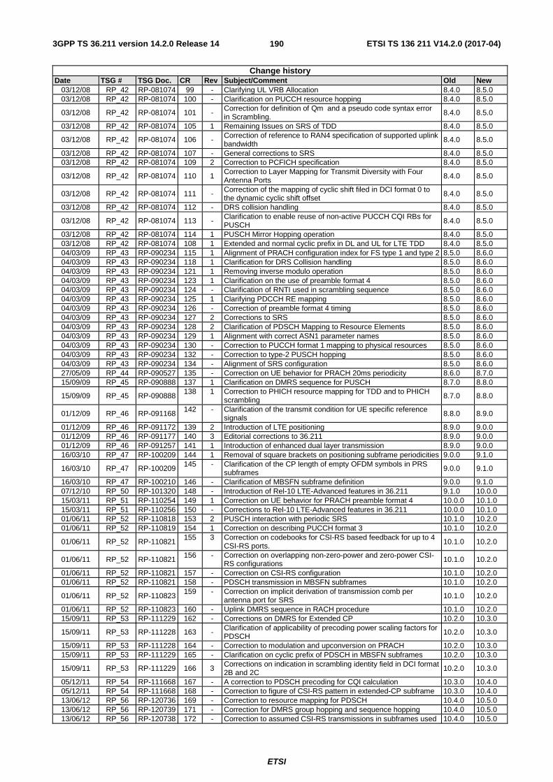
3GPP TS 36.211 version 14.2.0 Release 14 ETSI TS 136 211 V14.2.0 (2017-04)
ETSI
190
Change history Date TSG # TSG Doc. CR Rev Subject/Comment Old New
03/12/08 RP_42 RP-081074 99 - Clarifying UL VRB Allocation 8.4.0 8.5.0 03/12/08 RP_42 RP-081074 100 - Clarification on PUCCH resource hopping 8.4.0 8.5.0
03/12/08 RP_42 RP-081074 101 - Correction for definition of Qm and a pseudo code syntax error in Scrambling. 8.4.0 8.5.0
03/12/08 RP_42 RP-081074 105 1 Remaining Issues on SRS of TDD 8.4.0 8.5.0
03/12/08 RP_42 RP-081074 106 - Correction of reference to RAN4 specification of supported uplink bandwidth
8.4.0 8.5.0
03/12/08 RP_42 RP-081074 107 - General corrections to SRS 8.4.0 8.5.0 03/12/08 RP_42 RP-081074 109 2 Correction to PCFICH specification 8.4.0 8.5.0
03/12/08 RP_42 RP-081074 110 1 Correction to Layer Mapping for Transmit Diversity with Four Antenna Ports 8.4.0 8.5.0
03/12/08 RP_42 RP-081074 111 - Correction of the mapping of cyclic shift filed in DCI format 0 to the dynamic cyclic shift offset
8.4.0 8.5.0
03/12/08 RP_42 RP-081074 112 - DRS collision handling 8.4.0 8.5.0
03/12/08 RP_42 RP-081074 113 - Clarification to enable reuse of non-active PUCCH CQI RBs for PUSCH 8.4.0 8.5.0
03/12/08 RP_42 RP-081074 114 1 PUSCH Mirror Hopping operation 8.4.0 8.5.0 03/12/08 RP_42 RP-081074 108 1 Extended and normal cyclic prefix in DL and UL for LTE TDD 8.4.0 8.5.0 04/03/09 RP_43 RP-090234 115 1 Alignment of PRACH configuration index for FS type 1 and type 2 8.5.0 8.6.0 04/03/09 RP_43 RP-090234 118 1 Clarification for DRS Collision handling 8.5.0 8.6.0 04/03/09 RP_43 RP-090234 121 1 Removing inverse modulo operation 8.5.0 8.6.0 04/03/09 RP_43 RP-090234 123 1 Clarification on the use of preamble format 4 8.5.0 8.6.0 04/03/09 RP_43 RP-090234 124 - Clarification of RNTI used in scrambling sequence 8.5.0 8.6.0 04/03/09 RP_43 RP-090234 125 1 Clarifying PDCCH RE mapping 8.5.0 8.6.0 04/03/09 RP_43 RP-090234 126 - Correction of preamble format 4 timing 8.5.0 8.6.0 04/03/09 RP_43 RP-090234 127 2 Corrections to SRS 8.5.0 8.6.0 04/03/09 RP_43 RP-090234 128 2 Clarification of PDSCH Mapping to Resource Elements 8.5.0 8.6.0 04/03/09 RP_43 RP-090234 129 1 Alignment with correct ASN1 parameter names 8.5.0 8.6.0 04/03/09 RP_43 RP-090234 130 - Correction to PUCCH format 1 mapping to physical resources 8.5.0 8.6.0 04/03/09 RP_43 RP-090234 132 - Correction to type-2 PUSCH hopping 8.5.0 8.6.0 04/03/09 RP_43 RP-090234 134 - Alignment of SRS configuration 8.5.0 8.6.0 27/05/09 RP_44 RP-090527 135 - Correction on UE behavior for PRACH 20ms periodicity 8.6.0 8.7.0 15/09/09 RP_45 RP-090888 137 1 Clarification on DMRS sequence for PUSCH 8.7.0 8.8.0
15/09/09 RP_45 RP-090888 138 1 Correction to PHICH resource mapping for TDD and to PHICH
scrambling 8.7.0 8.8.0
01/12/09 RP_46 RP-091168 142 - Clarification of the transmit condition for UE specific reference signals
8.8.0 8.9.0
01/12/09 RP_46 RP-091172 139 2 Introduction of LTE positioning 8.9.0 9.0.0 01/12/09 RP_46 RP-091177 140 3 Editorial corrections to 36.211 8.9.0 9.0.0 01/12/09 RP_46 RP-091257 141 1 Introduction of enhanced dual layer transmission 8.9.0 9.0.0 16/03/10 RP_47 RP-100209 144 1 Removal of square brackets on positioning subframe periodicities 9.0.0 9.1.0
16/03/10 RP_47 RP-100209 145 - Clarification of the CP length of empty OFDM symbols in PRS
subframes 9.0.0 9.1.0
16/03/10 RP_47 RP-100210 146 - Clarification of MBSFN subframe definition 9.0.0 9.1.0 07/12/10 RP_50 RP-101320 148 - Introduction of Rel-10 LTE-Advanced features in 36.211 9.1.0 10.0.0 15/03/11 RP_51 RP-110254 149 1 Correction on UE behavior for PRACH preamble format 4 10.0.0 10.1.0 15/03/11 RP_51 RP-110256 150 - Corrections to Rel-10 LTE-Advanced features in 36.211 10.0.0 10.1.0 01/06/11 RP_52 RP-110818 153 2 PUSCH interaction with periodic SRS 10.1.0 10.2.0 01/06/11 RP_52 RP-110819 154 1 Correction on describing PUCCH format 3 10.1.0 10.2.0
01/06/11 RP_52 RP-110821 155 3 Correction on codebooks for CSI-RS based feedback for up to 4
CSI-RS ports. 10.1.0 10.2.0
01/06/11 RP_52 RP-110821 156 - Correction on overlapping non-zero-power and zero-power CSI-RS configurations 10.1.0 10.2.0
01/06/11 RP_52 RP-110821 157 - Correction on CSI-RS configuration 10.1.0 10.2.0 01/06/11 RP_52 RP-110821 158 - PDSCH transmission in MBSFN subframes 10.1.0 10.2.0
01/06/11 RP_52 RP-110823 159 - Correction on implicit derivation of transmission comb per
antenna port for SRS 10.1.0 10.2.0
01/06/11 RP_52 RP-110823 160 - Uplink DMRS sequence in RACH procedure 10.1.0 10.2.0 15/09/11 RP_53 RP-111229 162 - Corrections on DMRS for Extended CP 10.2.0 10.3.0
15/09/11 RP_53 RP-111228 163 - Clarification of applicability of precoding power scaling factors for PDSCH 10.2.0 10.3.0
15/09/11 RP_53 RP-111228 164 - Correction to modulation and upconversion on PRACH 10.2.0 10.3.0 15/09/11 RP_53 RP-111229 165 - Clarification on cyclic prefix of PDSCH in MBSFN subframes 10.2.0 10.3.0
15/09/11 RP_53 RP-111229 166 3 Corrections on indication in scrambling identity field in DCI format 2B and 2C
10.2.0 10.3.0
05/12/11 RP_54 RP-111668 167 - A correction to PDSCH precoding for CQI calculation 10.3.0 10.4.0 05/12/11 RP_54 RP-111668 168 - Correction to figure of CSI-RS pattern in extended-CP subframe 10.3.0 10.4.0 13/06/12 RP_56 RP-120736 169 - Correction to resource mapping for PDSCH 10.4.0 10.5.0 13/06/12 RP_56 RP-120739 171 - Correction for DMRS group hopping and sequence hopping 10.4.0 10.5.0 13/06/12 RP_56 RP-120738 172 - Correction to assumed CSI-RS transmissions in subframes used 10.4.0 10.5.0
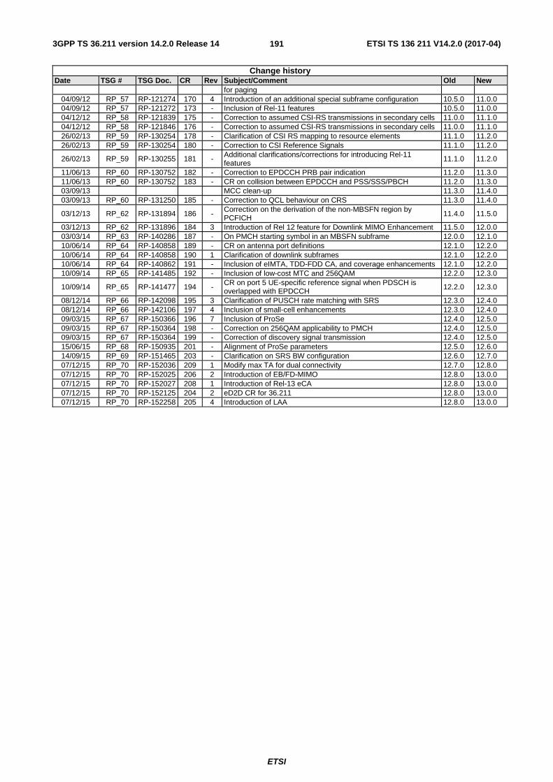
3GPP TS 36.211 version 14.2.0 Release 14 ETSI TS 136 211 V14.2.0 (2017-04)
ETSI
191
Change history Date TSG # TSG Doc. CR Rev Subject/Comment Old New
for paging 04/09/12 RP_57 RP-121274 170 4 Introduction of an additional special subframe configuration 10.5.0 11.0.0 04/09/12 RP_57 RP-121272 173 - Inclusion of Rel-11 features 10.5.0 11.0.0 04/12/12 RP_58 RP-121839 175 - Correction to assumed CSI-RS transmissions in secondary cells 11.0.0 11.1.0 04/12/12 RP_58 RP-121846 176 - Correction to assumed CSI-RS transmissions in secondary cells 11.0.0 11.1.0 26/02/13 RP_59 RP-130254 178 - Clarification of CSI RS mapping to resource elements 11.1.0 11.2.0 26/02/13 RP_59 RP-130254 180 - Correction to CSI Reference Signals 11.1.0 11.2.0
26/02/13 RP_59 RP-130255 181 - Additional clarifications/corrections for introducing Rel-11 features
11.1.0 11.2.0
11/06/13 RP_60 RP-130752 182 - Correction to EPDCCH PRB pair indication 11.2.0 11.3.0 11/06/13 RP_60 RP-130752 183 - CR on collision between EPDCCH and PSS/SSS/PBCH 11.2.0 11.3.0 03/09/13 MCC clean-up 11.3.0 11.4.0 03/09/13 RP_60 RP-131250 185 - Correction to QCL behaviour on CRS 11.3.0 11.4.0
03/12/13 RP_62 RP-131894 186 - Correction on the derivation of the non-MBSFN region by PCFICH 11.4.0 11.5.0
03/12/13 RP_62 RP-131896 184 3 Introduction of Rel 12 feature for Downlink MIMO Enhancement 11.5.0 12.0.0 03/03/14 RP_63 RP-140286 187 - On PMCH starting symbol in an MBSFN subframe 12.0.0 12.1.0 10/06/14 RP_64 RP-140858 189 - CR on antenna port definitions 12.1.0 12.2.0 10/06/14 RP_64 RP-140858 190 1 Clarification of downlink subframes 12.1.0 12.2.0 10/06/14 RP_64 RP-140862 191 - Inclusion of eIMTA, TDD-FDD CA, and coverage enhancements 12.1.0 12.2.0 10/09/14 RP_65 RP-141485 192 - Inclusion of low-cost MTC and 256QAM 12.2.0 12.3.0
10/09/14 RP_65 RP-141477 194 - CR on port 5 UE-specific reference signal when PDSCH is overlapped with EPDCCH 12.2.0 12.3.0
08/12/14 RP_66 RP-142098 195 3 Clarification of PUSCH rate matching with SRS 12.3.0 12.4.0 08/12/14 RP_66 RP-142106 197 4 Inclusion of small-cell enhancements 12.3.0 12.4.0 09/03/15 RP_67 RP-150366 196 7 Inclusion of ProSe 12.4.0 12.5.0 09/03/15 RP_67 RP-150364 198 - Correction on 256QAM applicability to PMCH 12.4.0 12.5.0 09/03/15 RP_67 RP-150364 199 - Correction of discovery signal transmission 12.4.0 12.5.0 15/06/15 RP_68 RP-150935 201 - Alignment of ProSe parameters 12.5.0 12.6.0 14/09/15 RP_69 RP-151465 203 - Clarification on SRS BW configuration 12.6.0 12.7.0 07/12/15 RP_70 RP-152036 209 1 Modify max TA for dual connectivity 12.7.0 12.8.0 07/12/15 RP_70 RP-152025 206 2 Introduction of EB/FD-MIMO 12.8.0 13.0.0 07/12/15 RP_70 RP-152027 208 1 Introduction of Rel-13 eCA 12.8.0 13.0.0 07/12/15 RP_70 RP-152125 204 2 eD2D CR for 36.211 12.8.0 13.0.0 07/12/15 RP_70 RP-152258 205 4 Introduction of LAA 12.8.0 13.0.0
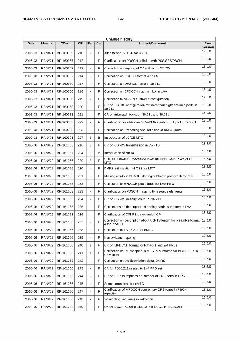
3GPP TS 36.211 version 14.2.0 Release 14 ETSI TS 136 211 V14.2.0 (2017-04)
ETSI
192
Change history Date Meeting TDoc CR Rev Cat Subject/Comment New
version
2016-03 RAN#71 RP-160359 210 - F Alignment eD2D CR for 36.211 13.1.0
2016-03 RAN#71 RP-160367 212 - F Clarification on PDSCH collision with PSS/SSS/PBCH 13.1.0
2016-03 RAN#71 RP-160357 213 - F Correction on support of CA with up to 32 CCs 13.1.0
2016-03 RAN#71 RP-160357 214 - F Correction on PUCCH format 4 and 5 13.1.0
2016-03 RAN#71 RP-160360 217 - F Correction on DRS subframe in 36.211 13.1.0
2016-03 RAN#71 RP-160360 218 - F Correction on EPDCCH start symbol in LAA 13.1.0
2016-03 RAN#71 RP-160360 219 - F Correction to MBSFN subframe configuration 13.1.0
2016-03 RAN#71 RP-160358 220 - F CR on CSI-RS configuration for more than eight antenna ports in 36.211
13.1.0
2016-03 RAN#71 RP-160358 221 - F CR on mismatch between 36.211 and 36.331 13.1.0
2016-03 RAN#71 RP-160358 222 - F Clarification on additional SC-FDMA symbols in UpPTS for SRS 13.1.0
2016-03 RAN#71 RP-160358 223 - F Correction on Precoding and definition of DMRS ports 13.1.0
2016-03 RAN#71 RP-160361 207 9 B Introduction of LC/CE MTC 13.1.0
2016-06 RAN#72 RP-161063 216 2 F CR on CSI-RS transmission in DwPTS 13.2.0
2016-06 RAN#72 RP-161067 224 8 B Introduction of NB-IoT 13.2.0
2016-06 RAN#72 RP-161066 229 2 F Collision between PSS/SSS/PBCH and MPDCCH/PDSCH for MTC
13.2.0
2016-06 RAN#72 RP-161066 230 - F DMRS initialization of CSS for MTC 13.2.0
2016-06 RAN#72 RP-161066 231 - F Missing words in PRACH starting subframe paragraph for MTC 13.2.0
2016-06 RAN#72 RP-161065 232 - F Correction to EPDCCH procedures for LAA FS 3 13.2.0
2016-06 RAN#72 RP-161063 233 - F Clarification on PDSCH mapping to resource elements 13.2.0
2016-06 RAN#72 RP-161063 234 - F CR on CSI-RS description in TS 36.211 13.2.0
2016-06 RAN#72 RP-161065 235 - F Corrections on the support of ending partial subframe in LAA 13.2.0
2016-06 RAN#72 RP-161063 236 - F Clarification of CSI-RS on extended CP 13.2.0
2016-06 RAN#72 RP-161063 237 - F Correction on description about UpPTS length for preamble format 4 for PRACH
13.2.0
2016-06 RAN#72 RP-161066 238 - F Correction to TS 36.211 for eMTC 13.2.0
2016-06 RAN#72 RP-161066 239 - F Narrow band hopping 13.2.0
2016-06 RAN#72 RP-161066 240 1 F CR on MPDCCH format for Rmax=1 and 2/4 PRBs 13.2.0
2016-06 RAN#72 RP-161066 241 1 F Correction on RE mapping in MBSFN subframe for BL/CE UEs in CEModeB
13.2.0
2016-06 RAN#72 RP-161063 242 - F Correction on the description about DMRS 13.2.0
2016-06 RAN#72 RP-161066 243 - F CR for TS36.211 related to 2+4 PRB set 13.2.0
2016-06 RAN#72 RP-161065 244 - F CR on UE assumptions on number of CRS ports in DRS 13.2.0
2016-06 RAN#72 RP-161066 245 - F Some corrections for eMTC 13.2.0
2016-06 RAN#72 RP-161066 247 - F Clarification of MPDCCH over empty CRS tones in PBCH repetition
13.2.0
2016-06 RAN#72 RP-161066 248 - F Scrambling sequence initialization 13.2.0
2016-06 RAN#72 RP-161066 249 - F On MPDCCH AL for 8 EREGs per ECCE in TS 36.211 13.2.0
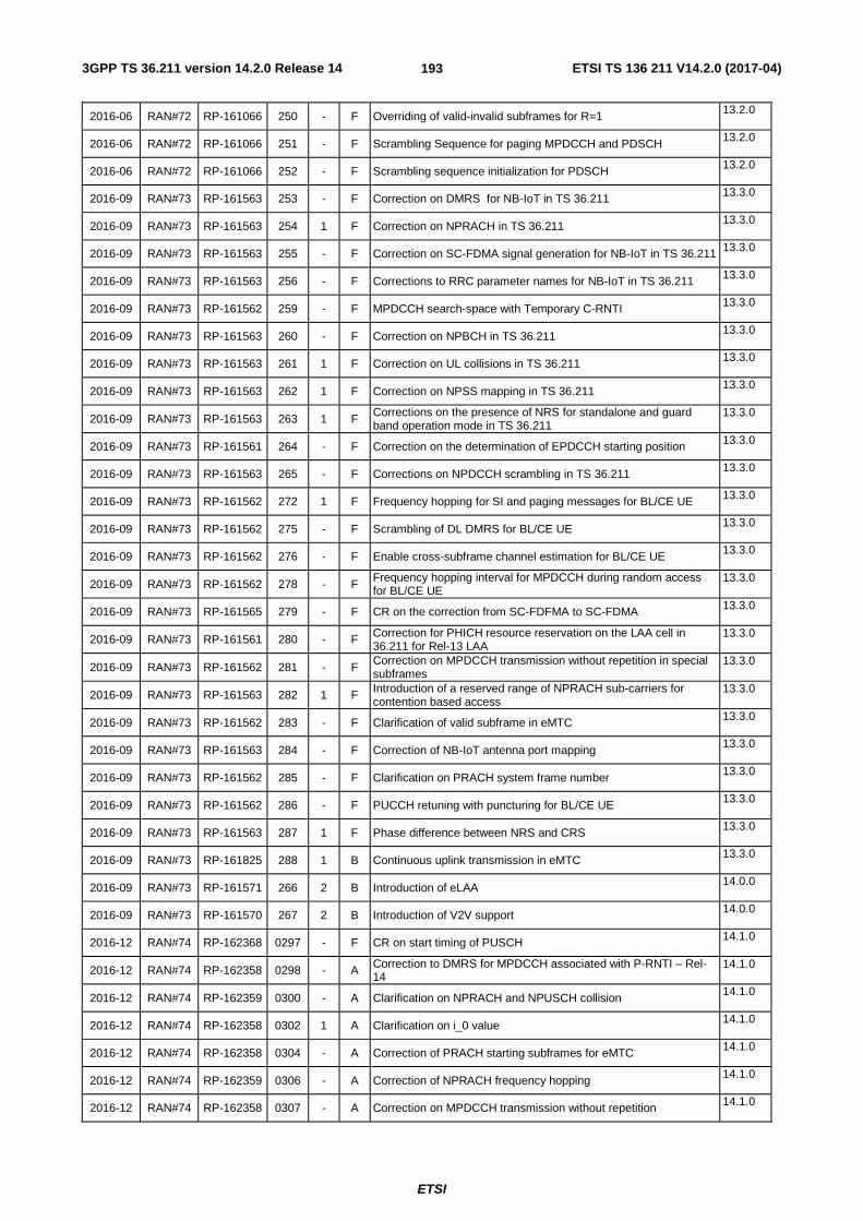
3GPP TS 36.211 version 14.2.0 Release 14 ETSI TS 136 211 V14.2.0 (2017-04)
ETSI
193
2016-06 RAN#72 RP-161066 250 - F Overriding of valid-invalid subframes for R=1 13.2.0
2016-06 RAN#72 RP-161066 251 - F Scrambling Sequence for paging MPDCCH and PDSCH 13.2.0
2016-06 RAN#72 RP-161066 252 - F Scrambling sequence initialization for PDSCH 13.2.0
2016-09 RAN#73 RP-161563 253 - F Correction on DMRS for NB-IoT in TS 36.211 13.3.0
2016-09 RAN#73 RP-161563 254 1 F Correction on NPRACH in TS 36.211 13.3.0
2016-09 RAN#73 RP-161563 255 - F Correction on SC-FDMA signal generation for NB-IoT in TS 36.211 13.3.0
2016-09 RAN#73 RP-161563 256 - F Corrections to RRC parameter names for NB-IoT in TS 36.211 13.3.0
2016-09 RAN#73 RP-161562 259 - F MPDCCH search-space with Temporary C-RNTI 13.3.0
2016-09 RAN#73 RP-161563 260 - F Correction on NPBCH in TS 36.211 13.3.0
2016-09 RAN#73 RP-161563 261 1 F Correction on UL collisions in TS 36.211 13.3.0
2016-09 RAN#73 RP-161563 262 1 F Correction on NPSS mapping in TS 36.211 13.3.0
2016-09 RAN#73 RP-161563 263 1 F Corrections on the presence of NRS for standalone and guard band operation mode in TS 36.211
13.3.0
2016-09 RAN#73 RP-161561 264 - F Correction on the determination of EPDCCH starting position 13.3.0
2016-09 RAN#73 RP-161563 265 - F Corrections on NPDCCH scrambling in TS 36.211 13.3.0
2016-09 RAN#73 RP-161562 272 1 F Frequency hopping for SI and paging messages for BL/CE UE 13.3.0
2016-09 RAN#73 RP-161562 275 - F Scrambling of DL DMRS for BL/CE UE 13.3.0
2016-09 RAN#73 RP-161562 276 - F Enable cross-subframe channel estimation for BL/CE UE 13.3.0
2016-09 RAN#73 RP-161562 278 - F Frequency hopping interval for MPDCCH during random access for BL/CE UE
13.3.0
2016-09 RAN#73 RP-161565 279 - F CR on the correction from SC-FDFMA to SC-FDMA 13.3.0
2016-09 RAN#73 RP-161561 280 - F Correction for PHICH resource reservation on the LAA cell in 36.211 for Rel-13 LAA
13.3.0
2016-09 RAN#73 RP-161562 281 - F Correction on MPDCCH transmission without repetition in special subframes
13.3.0
2016-09 RAN#73 RP-161563 282 1 F Introduction of a reserved range of NPRACH sub-carriers for contention based access
13.3.0
2016-09 RAN#73 RP-161562 283 - F Clarification of valid subframe in eMTC 13.3.0
2016-09 RAN#73 RP-161563 284 - F Correction of NB-IoT antenna port mapping 13.3.0
2016-09 RAN#73 RP-161562 285 - F Clarification on PRACH system frame number 13.3.0
2016-09 RAN#73 RP-161562 286 - F PUCCH retuning with puncturing for BL/CE UE 13.3.0
2016-09 RAN#73 RP-161563 287 1 F Phase difference between NRS and CRS 13.3.0
2016-09 RAN#73 RP-161825 288 1 B Continuous uplink transmission in eMTC 13.3.0
2016-09 RAN#73 RP-161571 266 2 B Introduction of eLAA 14.0.0
2016-09 RAN#73 RP-161570 267 2 B Introduction of V2V support 14.0.0
2016-12 RAN#74 RP-162368 0297 - F CR on start timing of PUSCH 14.1.0
2016-12 RAN#74 RP-162358 0298 - A Correction to DMRS for MPDCCH associated with P-RNTI – Rel-14
14.1.0
2016-12 RAN#74 RP-162359 0300 - A Clarification on NPRACH and NPUSCH collision 14.1.0
2016-12 RAN#74 RP-162358 0302 1 A Clarification on i_0 value 14.1.0
2016-12 RAN#74 RP-162358 0304 - A Correction of PRACH starting subframes for eMTC 14.1.0
2016-12 RAN#74 RP-162359 0306 - A Correction of NPRACH frequency hopping 14.1.0
2016-12 RAN#74 RP-162358 0307 - A Correction on MPDCCH transmission without repetition 14.1.0
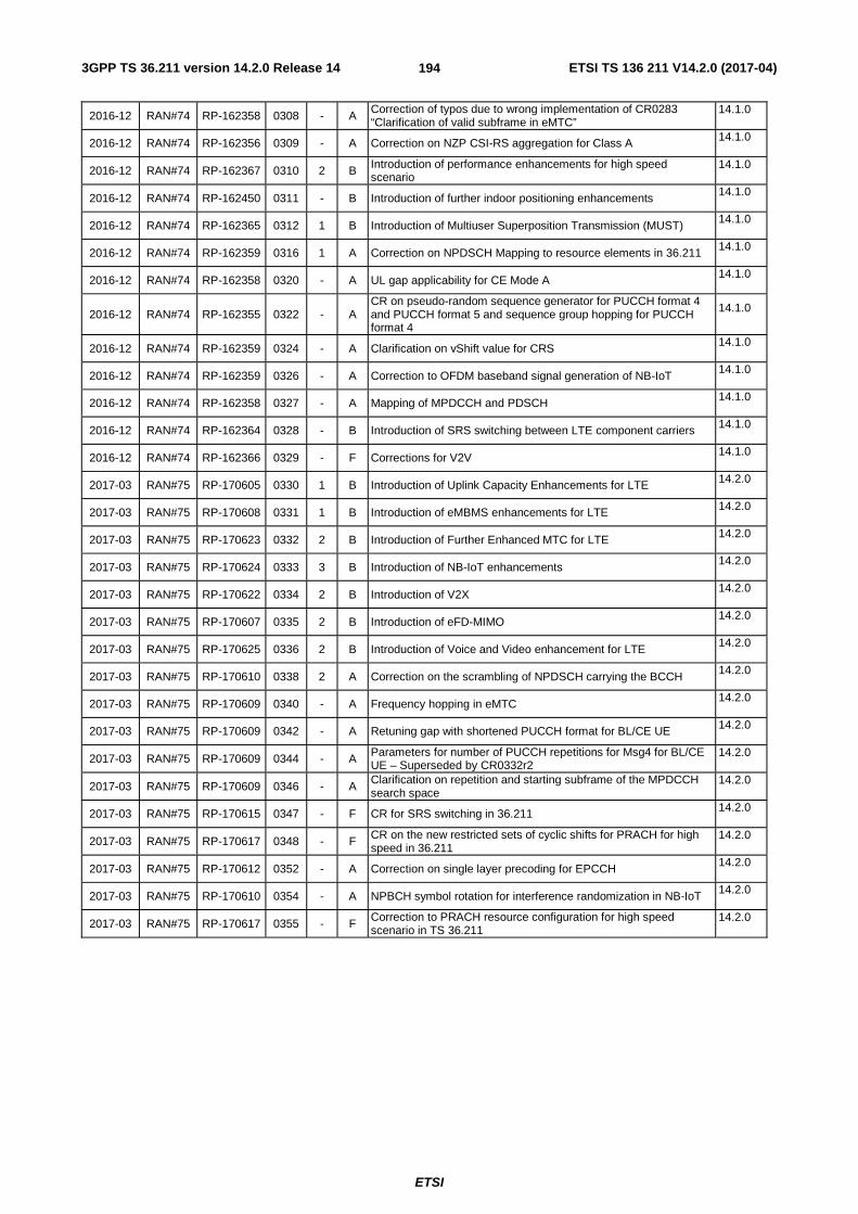
3GPP TS 36.211 version 14.2.0 Release 14 ETSI TS 136 211 V14.2.0 (2017-04)
ETSI
194
2016-12 RAN#74 RP-162358 0308 - A Correction of typos due to wrong implementation of CR0283 “Clarification of valid subframe in eMTC”
14.1.0
2016-12 RAN#74 RP-162356 0309 - A Correction on NZP CSI-RS aggregation for Class A 14.1.0
2016-12 RAN#74 RP-162367 0310 2 B Introduction of performance enhancements for high speed scenario
14.1.0
2016-12 RAN#74 RP-162450 0311 - B Introduction of further indoor positioning enhancements 14.1.0
2016-12 RAN#74 RP-162365 0312 1 B Introduction of Multiuser Superposition Transmission (MUST) 14.1.0
2016-12 RAN#74 RP-162359 0316 1 A Correction on NPDSCH Mapping to resource elements in 36.211 14.1.0
2016-12 RAN#74 RP-162358 0320 - A UL gap applicability for CE Mode A 14.1.0
2016-12 RAN#74 RP-162355 0322 - A CR on pseudo-random sequence generator for PUCCH format 4 and PUCCH format 5 and sequence group hopping for PUCCH format 4
14.1.0
2016-12 RAN#74 RP-162359 0324 - A Clarification on vShift value for CRS 14.1.0
2016-12 RAN#74 RP-162359 0326 - A Correction to OFDM baseband signal generation of NB-IoT 14.1.0
2016-12 RAN#74 RP-162358 0327 - A Mapping of MPDCCH and PDSCH 14.1.0
2016-12 RAN#74 RP-162364 0328 - B Introduction of SRS switching between LTE component carriers 14.1.0
2016-12 RAN#74 RP-162366 0329 - F Corrections for V2V 14.1.0
2017-03 RAN#75 RP-170605 0330 1 B Introduction of Uplink Capacity Enhancements for LTE 14.2.0
2017-03 RAN#75 RP-170608 0331 1 B Introduction of eMBMS enhancements for LTE 14.2.0
2017-03 RAN#75 RP-170623 0332 2 B Introduction of Further Enhanced MTC for LTE 14.2.0
2017-03 RAN#75 RP-170624 0333 3 B Introduction of NB-IoT enhancements 14.2.0
2017-03 RAN#75 RP-170622 0334 2 B Introduction of V2X 14.2.0
2017-03 RAN#75 RP-170607 0335 2 B Introduction of eFD-MIMO 14.2.0
2017-03 RAN#75 RP-170625 0336 2 B Introduction of Voice and Video enhancement for LTE 14.2.0
2017-03 RAN#75 RP-170610 0338 2 A Correction on the scrambling of NPDSCH carrying the BCCH 14.2.0
2017-03 RAN#75 RP-170609 0340 - A Frequency hopping in eMTC 14.2.0
2017-03 RAN#75 RP-170609 0342 - A Retuning gap with shortened PUCCH format for BL/CE UE 14.2.0
2017-03 RAN#75 RP-170609 0344 - A Parameters for number of PUCCH repetitions for Msg4 for BL/CE UE – Superseded by CR0332r2
14.2.0
2017-03 RAN#75 RP-170609 0346 - A Clarification on repetition and starting subframe of the MPDCCH search space
14.2.0
2017-03 RAN#75 RP-170615 0347 - F CR for SRS switching in 36.211 14.2.0
2017-03 RAN#75 RP-170617 0348 - F CR on the new restricted sets of cyclic shifts for PRACH for high speed in 36.211
14.2.0
2017-03 RAN#75 RP-170612 0352 - A Correction on single layer precoding for EPCCH 14.2.0
2017-03 RAN#75 RP-170610 0354 - A NPBCH symbol rotation for interference randomization in NB-IoT 14.2.0
2017-03 RAN#75 RP-170617 0355 - F Correction to PRACH resource configuration for high speed scenario in TS 36.211
14.2.0

3GPP TS 36.211 version 14.2.0 Release 14 ETSI TS 136 211 V14.2.0 (2017-04)
ETSI
195
History
Document history
V14.2.0 April 2017 Publication