ts 133 203 - v14.1.0 - digital cellular telecommunications ... · access security for ip-based...
TRANSCRIPT

ETSI TS 133 203 V14.1.0 (2017-07)
Digital cellular telecommunications system (Phase 2+) (GSM); Universal Mobile Telecommunications System (UMTS);
LTE; 3G security;
Access security for IP-based services (3GPP TS 33.203 version 14.1.0 Release 14)
TECHNICAL SPECIFICATION
ETSI
ETSI TS 133 203 V14.1.0 (2017-07)13GPP TS 33.203 version 14.1.0 Release 14
Reference RTS/TSGS-0333203ve10
Keywords GSM,LTE,SECURITY,UMTS
ETSI
650 Route des Lucioles F-06921 Sophia Antipolis Cedex - FRANCE
Tel.: +33 4 92 94 42 00 Fax: +33 4 93 65 47 16
Siret N° 348 623 562 00017 - NAF 742 C
Association à but non lucratif enregistrée à la Sous-Préfecture de Grasse (06) N° 7803/88
Important notice
The present document can be downloaded from: http://www.etsi.org/standards-search
The present document may be made available in electronic versions and/or in print. The content of any electronic and/or print versions of the present document shall not be modified without the prior written authorization of ETSI. In case of any
existing or perceived difference in contents between such versions and/or in print, the only prevailing document is the print of the Portable Document Format (PDF) version kept on a specific network drive within ETSI Secretariat.
Users of the present document should be aware that the document may be subject to revision or change of status. Information on the current status of this and other ETSI documents is available at
https://portal.etsi.org/TB/ETSIDeliverableStatus.aspx
If you find errors in the present document, please send your comment to one of the following services: https://portal.etsi.org/People/CommiteeSupportStaff.aspx
Copyright Notification
No part may be reproduced or utilized in any form or by any means, electronic or mechanical, including photocopying and microfilm except as authorized by written permission of ETSI.
The content of the PDF version shall not be modified without the written authorization of ETSI. The copyright and the foregoing restriction extend to reproduction in all media.
© ETSI 2017.
All rights reserved.
DECTTM, PLUGTESTSTM, UMTSTM and the ETSI logo are trademarks of ETSI registered for the benefit of its Members. 3GPPTM and LTE™ are trademarks of ETSI registered for the benefit of its Members and
of the 3GPP Organizational Partners. oneM2M logo is protected for the benefit of its Members.
GSM® and the GSM logo are trademarks registered and owned by the GSM Association.

ETSI
ETSI TS 133 203 V14.1.0 (2017-07)23GPP TS 33.203 version 14.1.0 Release 14
Intellectual Property Rights IPRs essential or potentially essential to the present document may have been declared to ETSI. The information pertaining to these essential IPRs, if any, is publicly available for ETSI members and non-members, and can be found in ETSI SR 000 314: "Intellectual Property Rights (IPRs); Essential, or potentially Essential, IPRs notified to ETSI in respect of ETSI standards", which is available from the ETSI Secretariat. Latest updates are available on the ETSI Web server (https://ipr.etsi.org/).
Pursuant to the ETSI IPR Policy, no investigation, including IPR searches, has been carried out by ETSI. No guarantee can be given as to the existence of other IPRs not referenced in ETSI SR 000 314 (or the updates on the ETSI Web server) which are, or may be, or may become, essential to the present document.
Foreword This Technical Specification (TS) has been produced by ETSI 3rd Generation Partnership Project (3GPP).
The present document may refer to technical specifications or reports using their 3GPP identities, UMTS identities or GSM identities. These should be interpreted as being references to the corresponding ETSI deliverables.
The cross reference between GSM, UMTS, 3GPP and ETSI identities can be found under http://webapp.etsi.org/key/queryform.asp.
Modal verbs terminology In the present document "shall", "shall not", "should", "should not", "may", "need not", "will", "will not", "can" and "cannot" are to be interpreted as described in clause 3.2 of the ETSI Drafting Rules (Verbal forms for the expression of provisions).
"must" and "must not" are NOT allowed in ETSI deliverables except when used in direct citation.

ETSI
ETSI TS 133 203 V14.1.0 (2017-07)33GPP TS 33.203 version 14.1.0 Release 14
Contents
Intellectual Property Rights ................................................................................................................................ 2
Foreword ............................................................................................................................................................. 2
Modal verbs terminology .................................................................................................................................... 2
Foreword ............................................................................................................................................................. 9
1 Scope ...................................................................................................................................................... 10
2 References .............................................................................................................................................. 10
3 Definitions, symbols and abbreviations ................................................................................................. 13
3.1 Definitions ........................................................................................................................................................ 13
3.2 Symbols ............................................................................................................................................................ 13
3.3 Abbreviations ................................................................................................................................................... 13
4 Overview of the security architecture..................................................................................................... 14
5 Security features ..................................................................................................................................... 17
5.1 Secure access to IMS ........................................................................................................................................ 17
5.1.1 Authentication of the subscriber and the network ....................................................................................... 17
5.1.2 Re-Authentication of the subscriber ........................................................................................................... 17
5.1.3 Confidentiality protection ........................................................................................................................... 17
5.1.4 Integrity protection ..................................................................................................................................... 18
5.2 Network topology hiding .................................................................................................................................. 18
5.3 SIP Privacy handling in IMS Networks ........................................................................................................... 18
5.4 SIP Privacy handling when interworking with non-IMS Networks ................................................................. 19
6 Security mechanisms .............................................................................................................................. 19
6.1 Authentication and key agreement ................................................................................................................... 19
6.1.0 General ........................................................................................................................................................ 19
6.1.1 Authentication of an IM-subscriber ............................................................................................................ 19
6.1.2 Authentication failures ................................................................................................................................ 22
6.1.2.1 User authentication failure .................................................................................................................... 22
6.1.2.2 Network authentication failure .............................................................................................................. 22
6.1.2.3 Incomplete authentication ..................................................................................................................... 23
6.1.3 Synchronization failure ............................................................................................................................... 23
6.1.4 Network Initiated authentications ............................................................................................................... 24
6.1.5 Integrity protection indicator ...................................................................................................................... 25
6.2 Confidentiality mechanisms ............................................................................................................................. 25
6.3 Integrity mechanisms ....................................................................................................................................... 26
6.4 Hiding mechanisms .......................................................................................................................................... 26
6.5 CSCF interoperating with proxy located in a non-IMS network ...................................................................... 26
7 Security association set-up procedure .................................................................................................... 27
7.0 General ............................................................................................................................................................. 27
7.1 Security association parameters ....................................................................................................................... 27
7.2 Set-up of security associations (successful case) .............................................................................................. 30
7.3 Error cases in the set-up of security associations ............................................................................................. 33
7.3.1 Error cases related to IMS AKA ................................................................................................................. 33
7.3.1.0 General .................................................................................................................................................. 33
7.3.1.1 User authentication failure .................................................................................................................... 33
7.3.1.2 Network authentication failure .............................................................................................................. 33
7.3.1.3 Synchronisation failure ......................................................................................................................... 33
7.3.1.4 Incomplete authentication ..................................................................................................................... 33
7.3.2 Error cases related to the Security-Set-up ................................................................................................... 33
7.3.2.1 Proposal unacceptable to P-CSCF ......................................................................................................... 33
7.3.2.2 Proposal unacceptable to UE................................................................................................................. 33
7.3.2.3 Failed consistency check of Security-Set-up lines at the P-CSCF ........................................................ 34
7.4 Authenticated re-registration ............................................................................................................................ 34
7.4.0 General ........................................................................................................................................................ 34

ETSI
ETSI TS 133 203 V14.1.0 (2017-07)43GPP TS 33.203 version 14.1.0 Release 14
7.4.1 Void ............................................................................................................................................................ 34
7.4.1a Management of security associations in the UE ......................................................................................... 34
7.4.2 Void ............................................................................................................................................................ 35
7.4.2a Management of security associations in the P-CSCF ................................................................................. 35
7.5 Rules for security association handling when the UE changes IP address ....................................................... 36
8 ISIM ....................................................................................................................................................... 36
8.0 General ............................................................................................................................................................. 36
8.1 Requirements on the ISIM application ............................................................................................................. 37
8.2 Sharing security functions and data with the USIM ......................................................................................... 37
9 IMC ........................................................................................................................................................ 38
Annex A: Void ................................................................................................................. 39
Annex B: Void ................................................................................................................. 40
Annex C: Void ................................................................................................................. 41
Annex D: Void ................................................................................................................ 42
Annex E: Void ................................................................................................................. 43
Annex F: Void ................................................................................................................. 44
Annex G (informative): Management of sequence numbers .............................................................. 45
Annex H (normative): The use of "Security Mechanism Agreement for SIP Sessions" [21] for security mode set-up ................................................................................ 46
Annex I (normative): Key expansion functions for IPsec ESP ....................................................... 48
Annex J (informative): Recommendations to protect the IMS from UEs bypassing the P-CSCF ........................................................................................................... 49
Annex K: Void ................................................................................................................. 50
Annex L (Normative): Application to fixed broadband access ........................................................ 51
L.1 Introduction ............................................................................................................................................ 51
L.2 Application of clause 4 ........................................................................................................................... 51
Annex M (normative): Enhancements to the access security for IP based services to enable NAT traversal for signaling messages .......................................................... 53
M.0 General ................................................................................................................................................... 53
M.1 Scope ...................................................................................................................................................... 53
M.2 References .............................................................................................................................................. 53
M.3 Definitions, symbols and abbreviations ................................................................................................. 53
M.4 Overview of the security architecture..................................................................................................... 53
M.5 Security features ..................................................................................................................................... 53
M.6 Security mechanisms .............................................................................................................................. 54
M.6.1 Authentication and key agreement ................................................................................................................... 54
M.6.2 Confidentiality mechanisms ............................................................................................................................. 54
M.6.3 Integrity mechanisms ....................................................................................................................................... 54
M.6.4 Hiding mechanisms .......................................................................................................................................... 54
M.6.5 CSCF interoperating with proxy located in a non-IMS network ...................................................................... 55
M.7 Security association set-up procedure .................................................................................................... 55
M.7.0 General ............................................................................................................................................................. 55

ETSI
ETSI TS 133 203 V14.1.0 (2017-07)53GPP TS 33.203 version 14.1.0 Release 14
M.7.1 Security association parameters ....................................................................................................................... 55
M.7.2 Set-up of security associations (successful case) .............................................................................................. 59
M.7.3 Error cases in the set-up of security associations ............................................................................................. 64
M.7.3.1 Error cases related to IMS AKA ................................................................................................................. 64
M.7.3.2 Error cases related to the Security-Set-up ................................................................................................... 64
M.7.3.2.1 Proposal unacceptable to P-CSCF ......................................................................................................... 64
M.7.3.2.2 Proposal unacceptable to UE................................................................................................................. 64
M.7.3.2.3 Failed consistency check of Security-Set-up lines at the P-CSCF ........................................................ 64
M.7.3.2.4 Missing NAT traversal capabilities in the presence of a NAT .............................................................. 64
M.7.4 Authenticated re-registration ............................................................................................................................ 64
M.7.4.0 General ........................................................................................................................................................ 64
M.7.4.1 Void ............................................................................................................................................................ 65
M.7.4.1a Management of security associations in the UE ......................................................................................... 65
M.7.4.2 Void ............................................................................................................................................................ 65
M.7.4.2a Management of security associations in the P-CSCF ................................................................................. 65
M.7.5 Rules for security association handling when the UE changes IP address ....................................................... 66
M.8 ISIM ....................................................................................................................................................... 67
M.9 IMC ........................................................................................................................................................ 67
Annex N (normative): Enhancements to the access security to enable SIP Digest ......................... 68
N.1 SIP Digest ............................................................................................................................................... 68
N.2 Authentication ........................................................................................................................................ 68
N.2.1 Authentication Requirements ........................................................................................................................... 68
N.2.1.1 Authentication Requirements for Registrations .......................................................................................... 68
N.2.1.2 Authentication Requirements for Non-registration Messages .................................................................... 71
N.2.2 Authentication failures ..................................................................................................................................... 73
N.2.2.1 User Authentication failure ......................................................................................................................... 73
N.2.2.2 Network authentication failure ................................................................................................................... 73
N.2.2.3 Incomplete Authentication .......................................................................................................................... 73
N.2.3 SIP Digest synchronization failure ................................................................................................................... 73
N.2.4 Network Initiated authentications ..................................................................................................................... 74
N.2.5 Support for dynamic password change ............................................................................................................. 74
Annex O (normative): Enhancements to the access security to enable TLS ................................... 76
O.1 TLS ......................................................................................................................................................... 76
O.1.1 TLS Access Security ........................................................................................................................................ 76
O.1.2 Confidentiality protection ................................................................................................................................. 76
O.1.3 Integrity protection ........................................................................................................................................... 76
O.1.4 TLS integrity protection indicator .................................................................................................................... 77
O.2 TLS Session set-up procedure ................................................................................................................ 77
O.2.1 TLS Profile for TLS based access security....................................................................................................... 77
O.2.2 TLS session set-up during registration ............................................................................................................. 78
O.2.3 TLS session set-up prior to Initial registration ................................................................................................. 79
O.3 Error cases in the set-up of TLS sessions ............................................................................................... 79
O.3.1 Error cases related to TLS ................................................................................................................................ 79
O.3.1.0 General ........................................................................................................................................................ 79
O.3.1.1 User authentication failure .......................................................................................................................... 79
O.3.1.2 Network authentication failure ................................................................................................................... 80
O.3.1.3 Synchronisation failure ............................................................................................................................... 80
O.3.1.4 Incomplete authentication ........................................................................................................................... 80
O.3.2 Error cases related to the Security-Set-Up ....................................................................................................... 80
O.4 Management of TLS sessions................................................................................................................. 80
O.4.1 Management of TLS sessions at the UE ........................................................................................................... 80
O.4.2 Management of TLS sessions at the P-CSCF ................................................................................................... 80
O.4.3 Authenticated re-registration ............................................................................................................................ 80
O.5 TLS Certificate Profile and Validation................................................................................................... 81
ETSI
ETSI TS 133 203 V14.1.0 (2017-07)63GPP TS 33.203 version 14.1.0 Release 14
O.5.1 TLS Certificate ................................................................................................................................................. 81
O.5.2 Certificate validation ........................................................................................................................................ 81
O.5.3 Certificate Revocation ...................................................................................................................................... 82
Annex P (normative): Co-existence of authentication schemes IMS AKA, GPRS-IMS-Bundled Authentication, NASS-IMS-bundled authentication, SIP Digest and Trusted Node Authentication .................................................... 83
P.1 Scope of this Annex ............................................................................................................................... 83
P.2 Requirements on co-existence of authentication schemes ..................................................................... 83
P.3 P-CSCF procedure selection .................................................................................................................. 83
P.4 Determination of requested authentication scheme in S-CSCF ............................................................. 85
P.4.1 Stepwise approach ............................................................................................................................................ 85
P.4.2 Mechanisms for performing steps 1 to 3 in P.4.1 ............................................................................................. 86
P.5 Co-existence of PANI-aware and other P-CSCFs .................................................................................. 87
P.6 Considerations on the Cx interface ........................................................................................................ 87
Annex Q (informative): Usage of the authentication mechanisms for non-registration messages in Annexes N and O ....................................................................... 88
Q.1 General ................................................................................................................................................... 88
Q.2 Assertion of identities by the P-CSCF.................................................................................................... 88
Q.3 Strengths and boundary conditions for the use of authentication mechanisms for non-registration messages ................................................................................................................................................. 89
Annex R (normative): NASS-IMS-bundled authentication ............................................................. 91
R.1 Overview ................................................................................................................................................ 91
R.2 Use Cases and Limitations ..................................................................................................................... 91
R.3 Detailed description ................................................................................................................................ 91
Annex S (Normative): Application to 3GPP2 Access ........................................................................ 94
S.1 Introduction ............................................................................................................................................ 94
S.2 Application of clause 4 ........................................................................................................................... 94
S.3 Application of clauses 5 through 9 ......................................................................................................... 95
S.4 3GPP2 AKA Credentials ........................................................................................................................ 96
S.4.1 Realisations of 3GPP2 AKA Credentials ......................................................................................................... 96
S.5 Network Domain Security for IMS ........................................................................................................ 96
S.5.1 General ............................................................................................................................................................. 96
S.5.2 Inter-domain Domain Security ......................................................................................................................... 96
S.5.3 Intra-domain Domain Security ......................................................................................................................... 97
S.5.4 Profiles of Network Domain Security Methods ............................................................................................... 97
S.5.4.1 General ........................................................................................................................................................ 97
S.5.4.2 Support of IPsec ESP .................................................................................................................................. 97
S.5.4.2.1 General .................................................................................................................................................. 97
S.5.4.2.2 Support of ESP authentication and encryption ...................................................................................... 97
S.5.4.3 Support of TLS ........................................................................................................................................... 98
Annex T (normative): GPRS-IMS-Bundled Authentication (GIBA) for Gm interface ............... 99
T.1 Introduction ............................................................................................................................................ 99
T.2 Requirements .......................................................................................................................................... 99
T.3 Threat Scenarios ................................................................................................................................... 100
ETSI
ETSI TS 133 203 V14.1.0 (2017-07)73GPP TS 33.203 version 14.1.0 Release 14
T.3.0 General ........................................................................................................................................................... 100
T.3.1 Impersonation on IMS level using the identity of an innocent user ............................................................... 100
T.3.2 IP spoofing ..................................................................................................................................................... 100
T.3.3 Combined threat scenario ............................................................................................................................... 100
T.4 GIBA Security Mechanism .................................................................................................................. 101
T.5 Restrictions imposed by GIBA ............................................................................................................. 101
T.6 Protection against IP address spoofing in GGSN ................................................................................. 102
T.7 Interworking cases ................................................................................................................................ 102
T.8 Message Flows ..................................................................................................................................... 105
T.8.1 Successful registration .................................................................................................................................... 105
T.8.2 Unsuccessful registration ............................................................................................................................... 106
T.8.3 Successful registration for a selected interworking case ................................................................................ 108
Annex U (normative): Trusted Node Authentication (TNA) ........................................................ 111
U.1 Overview .............................................................................................................................................. 111
U.2 Use case and detailed description ......................................................................................................... 111
Annex V (informative): NAT deployment considerations for GIBA .............................................. 114
Annex W (normative): Tunnelling of IMS Services over Restrictive Access Networks ............... 115
W.1 Overview .............................................................................................................................................. 115
W.2 Service and Media Reachability for Users over Restrictive Firewalls – Tunneled Firewall Traversal for IMS traffic ...................................................................................................................... 115
W.2.0 General ........................................................................................................................................................... 115
W.2.1 Firewall detection procedure .......................................................................................................................... 116
W.3 Service and Media Reachability for Users over Restrictive Firewalls – Extensions to STUN/TURN/ICE ................................................................................................................................ 117
W.3.1 Introduction .................................................................................................................................................... 118
W.3.1.1 General ...................................................................................................................................................... 118
W.3.1.2 Firewall traversal for IMS control plane using SIP over TLS/TCP .......................................................... 118
W.3.1.3 Firewall traversal for IMS media plane using ICE and TURN ................................................................. 118
W.3.2 Reference model ............................................................................................................................................. 119
W.3.3 Required functions of the UE ......................................................................................................................... 119
W.3.4 Required functions of the P-CSCF ................................................................................................................. 120
W.3.5 Required functions of the TURN server ......................................................................................................... 120
W.3.6 Required functions of the IMS-ALG and IMS-AGW .................................................................................... 120
Annex X (Normative): Security for WebRTC IMS Client access to IMS ..................................... 121
X.1 Introduction .......................................................................................................................................... 121
X.2 Authentication of WebRTC IMS Client with IMS subscription re-using existing IMS authentication mechanisms ................................................................................................................... 121
X.2.0 General ........................................................................................................................................................... 121
X.2.1 General requirements ..................................................................................................................................... 121
X.2.2 Solution 1.1: Use of SIP Digest credentials.................................................................................................... 121
X.2.2.1 General ...................................................................................................................................................... 121
X.2.2.2 Requirements ............................................................................................................................................ 122
X.2.2.3 Procedures................................................................................................................................................. 122
X.2.3 Solution 1.2: Use of IMS AKA ...................................................................................................................... 123
X.2.3.1 General ...................................................................................................................................................... 123
X.2.3.2 Requirements ............................................................................................................................................ 124
X.2.3.3 Procedures................................................................................................................................................. 124
X.3 Authentication of WebRTC IMS Client with IMS subscription using web credentials ....................... 125
X.3.0 General ........................................................................................................................................................... 125
X.3.1 General requirements ..................................................................................................................................... 126

ETSI
ETSI TS 133 203 V14.1.0 (2017-07)83GPP TS 33.203 version 14.1.0 Release 14
X.3.2 Solution 2.1 .................................................................................................................................................... 126
X.3.2.1 General ...................................................................................................................................................... 126
X.3.2.2 Requirements ............................................................................................................................................ 126
X.3.2.3 Procedures................................................................................................................................................. 127
X.4 Assignment of IMS identities to WebRTC IMS Client from pool of IMS subscriptions held by WWSF .................................................................................................................................................. 131
X.4.0 General ........................................................................................................................................................... 131
X.4.1 General requirements ..................................................................................................................................... 131
X.4.2 Solution 3.1 .................................................................................................................................................... 132
X.4.2.1 General ...................................................................................................................................................... 132
X.4.2.2 Requirements ............................................................................................................................................ 132
X.4.2.3 Procedures................................................................................................................................................. 132
X.5 TURN credential provisioning and authentication (informative)......................................................... 136
X.5.1 Introduction .................................................................................................................................................... 136
X.5.2 Solution 1: TURN credential provisioning and authentication using eP-CSCF ............................................. 137
X.5.2.1 Overview .................................................................................................................................................. 137
X.5.2.2 Procedures................................................................................................................................................. 137
X.5.3 Solution 2: TURN credential provisioning and authentication using OAuth Access token ........................... 138
X.5.3.1 Overview .................................................................................................................................................. 138
X.5.3.2 Procedures................................................................................................................................................. 139
Annex Y (informative): Change history ............................................................................................. 142
History ............................................................................................................................................................ 147

ETSI
ETSI TS 133 203 V14.1.0 (2017-07)93GPP TS 33.203 version 14.1.0 Release 14
Foreword This Technical Specification has been produced by the 3rd Generation Partnership Project (3GPP).
The contents of the present document are subject to continuing work within the TSG and may change following formal TSG approval. Should the TSG modify the contents of the present document, it will be re-released by the TSG with an identifying change of release date and an increase in version number as follows:
Version x.y.z
where:
x the first digit:
1 presented to TSG for information;
2 presented to TSG for approval;
3 or greater indicates TSG approved document under change control.
y the second digit is incremented for all changes of substance, i.e. technical enhancements, corrections, updates, etc.
z the third digit is incremented when editorial only changes have been incorporated in the document.
ETSI
ETSI TS 133 203 V14.1.0 (2017-07)103GPP TS 33.203 version 14.1.0 Release 14
1 Scope The scope for this technical specification is to specify the security features and mechanisms for secure access to the IM subsystem (IMS) for the 3G mobile telecommunication system.
Since the scope also encompasses the use of these security features and mechanisms for secure access to IMS in the context of fixed broadband networks and 3GPP2 networks, Annex L and Annex S specify how the material in the main body and other normative Annexes of this document apply to the fixed broadband networks and 3GPP2 networks respectively.
The IMS supports IP Multimedia applications such as video, audio and multimedia conferences. SIP, Session Initiation Protocol, was chosen as the signalling protocol for creating and terminating Multimedia sessions, cf. RFC 3261 [6]. This specification only deals with how the SIP signalling is protected between the subscriber and the IMS, how the subscriber is authenticated and how the subscriber authenticates the IMS.
2 References The following documents contain provisions which, through reference in this text, constitute provisions of the present document.
• References are either specific (identified by date of publication, edition number, version number, etc.) or non-specific.
• For a specific reference, subsequent revisions do not apply.
• For a non-specific reference, the latest version applies. In the case of a reference to a 3GPP document (including a GSM document), a non-specific reference implicitly refers to the latest version of that document in the same Release as the present document.
[1] 3GPP TS 33.102: "3rd Generation Partnership Project; Technical Specification Group Services and System Aspects; 3G Security; Security Architecture".
[2] Void.
[3] 3GPP TS 23.228: "3rd Generation Partnership Project; Technical Specification Group Services and System Aspects; IP Multimedia (IM) Subsystem".
[4] Void.
[5] 3GPP TS 33.210: "3rd Generation Partnership Project; Technical Specification Group Services and System Aspects; 3G Security; Network domain security; IP network layer security".
[6] IETF RFC 3261 "SIP: Session Initiation Protocol".
[7] 3GPP TS 21.905: "3rd Generation Partnership Project: Technical Specification Group Services and System Aspects; Vocabulary for 3GPP specifications".
[8] 3GPP TS 24.229: "3rd Generation Partnership Project: Technical Specification Group Core Network; IP Multimedia Call Control Protocol based on SIP and SDP".
[9] 3GPP TS 23.002: "3rd Generation Partnership Project: Technical Specification Group Services and System Aspects, Network Architecture".
[10] 3GPP TS 23.060: "3rd Generation Partnership Project: Technical Specification Group Services and System Aspects, General Packet Radio Service (GPRS); Service Description".
[11] 3GPP TS 24.228: "3rd Generation Partnership Project: Technical Specification Group Core Network; Signalling flows for the IP multimedia call control based on SIP and SDP".
[12] IETF RFC 2617 (1999) "HTTP Authentication: Basic and Digest Access Authentication".
[13]-[16] Void.

ETSI
ETSI TS 133 203 V14.1.0 (2017-07)113GPP TS 33.203 version 14.1.0 Release 14
[17] IETF RFC 3310 (2002): "HTTP Digest Authentication Using AKA". April, 2002.
[18] IETF RFC 3041 (2001): "Privacy Extensions for Stateless Address Autoconfiguration in IPv6".
[19] Void.
[20] IETF RFC 2451 (1998): "The ESP CBC-Mode Cipher Algorithms".
[21] IETF RFC 3329 (2003): "Security Mechanism Agreement for the Session Initiation Protocol (SIP)".
[22] IETF RFC 3602 (2003): "The AES-CBC Cipher Algorithm and Its Use with IPsec".
[23] IETF RFC 3263 (2002): "Session Initiation Protocol (SIP): Locating SIP Servers".
[24] 3GPP TS 33.310: "3rd Generation Partnership Project; Technical Specification Group Services and System Aspects; Network Domain Security (NDS); Authentication Framework (AF)".
[25] Void.
[26] ETSI ES 282 001: "TISPAN - Telecommunications and Internet converged Services and Protocols for Advanced Networking (TISPAN); NGN Functional Architecture for NGN Release 1".
[27] IETF RFC 3947 (2005): "Negotiation of NAT-Traversal in the IKE".
[28] IETF RFC 3948 (2005): "UDP Encapsulation of IPsec ESP Packets".
[29] IETF RFC 3323 (2002): "A Privacy Mechanism for the Session Initiation Protocol (SIP)".
[30] IETF RFC 3325 (2002): "Private Extensions to the Session Initiation Protocol (SIP) for Asserted Identity within Trusted Network".
[31] 3GPP TS 23.167: "3rd Generation Partnership Project; Technical Specification Group Services and System Aspects; IP Multimedia Subsystem (IMS) emergency sessions”.
[32] IETF RFC 5626 (2009): "Managing Client Initiated Connections in the Session Initiation Protocol (SIP)".
[33] Void.
[34] IETF RFC 2246 (1999): "The TLS Protocol Version 1.0".
[35] Void.
[36] ETSI ES 282 004: “NGN Functional Architecture; Network Attachment Sub-System (NASS)”
[37] ETSI TS 187 001: " Telecommunications and Internet converged Services and Protocols for Advanced Networking (TISPAN); NGN SECurity (SEC); Requirements"
[38] Void.
[39] 3GPP TS 29.228: "3rd Generation Partnership Project; Technical Specification Group Core Network and Terminals; IP Multimedia (IM) Subsystem Cx and Dx interfaces; Signalling flows and message contents".
[40] 3GPP2 X.S0011: "cdma2000 Wireless IP Network Standard".
[41] 3GPP2 C.S0023: "Removable User Identity Module for Spread Spectrum Systems".
[42] Void.
[43] 3GPP2 S.S0055: "Enhanced Cryptographic Algorithms".
[44] 3GPP2 S.S0078: "Common Security Algorithms".
[45] 3GPP2 C.S0065: "cdma2000 Application on UICC for Spread Spectrum Systems".

ETSI
ETSI TS 133 203 V14.1.0 (2017-07)123GPP TS 33.203 version 14.1.0 Release 14
[46] 3GPP TS 23.003: "3rd Generation Partnership Project; Technical Specification Group Core Network and Terminals; Numbering, addressing and identification".
[47] IETF RFC-2407: "The Internet IP Security Domain of Interpretation for ISAKMP".
[48] IETF RFC-2408: "Internet Security Association and Key Management Protocol (ISAKMP)".
[49] IETF RFC-2409: "The Internet Key Exchange (IKE)".
[50] 3GPP TS 23.292: "IP Multimedia Subsystem (IMS) Centralized Services; Stage 2".
[51] 3GPP TS 31.103: "3rd Generation Partnership Project: Technical Specification Group Core Network and Terminals; Characteristics of the IP Multimedia Services Identity Module (ISIM) application".
[52] IETF RFC 5280: "Internet X.509 Public Key Infrastructure Certificate and Certificate Revocation List (CRL) Profile".
[53] IETF RFC 4301: "Security Architecture for the Internet Protocol".
[54] IETF RFC 4303: "IP Encapsulating Security Payload (ESP)".
[55] 3GPP TS 33.401: "3GPP System Architecture Evolution (SAE); Security architecture".
[56] 3GPP TS 23.401: "General Packet Radio Service (GPRS) enhancements for Evolved Universal Terrestrial Radio Access Network (E-UTRAN) access".
[57] ETSI TS 187 003 v3.4.1: "Telecommunications and Internet converged Services and Protocols for Advanced Networking (TISPAN); NGN Security; Security Architecture".
[58] Void.
[59] IETF RFC 5245: "Interactive Connectivity Establishment (ICE)".
[60] IETF RFC 6544: "TCP Candidates with Interactive Connectivity Establishment (ICE) ".
[61] IETF RFC 5766: "Traversal Using Relays around NAT (TURN)".
[62] IETF RFC 6062: "Traversal Using Relays around NAT (TURN) Extensions for TCP Allocations".
[63] IETF RFC 2817: "Upgrading to TLS Within HTTP/1.1".
[64] IETF RFC 6623: "Indication of Support for Keep-Alive".
[65] IETF RFC 4169: "Hypertext Transfer Protocol (HTTP) Digest Authentication Using Authentication and Key Agreement (AKA) Version-2”.
[66] 3GPP TS 33.220: "Generic Authentication Architecture (GAA); Generic Bootstrapping Architecture (GBA)".
[67] IETF RFC 6750: "The OAuth 2.0 Authorization Framework: Bearer Token Usage".
[68] IETF RFC 7376: "Problems with Session Traversal Utilities for NAT (STUN) Long-Term Authentication for Traversal Using Relays around NAT (TURN)".
[69] IETF RFC 5389: "Session Traversal Utilities for NAT (STUN)".
[70] IETF draft "draft-ietf-tram-turn-third-party-authz-16 ": "Session Traversal Utilities for NAT (STUN) Extension for Third Party Authorization".
[71] IETF draft "draft-ietf-oauth-pop-architecture-02" : "OAuth 2.0 Proof-of-Possession (PoP) Security Architecture".
[72] IETF RFC 6749: "The OAuth 2.0 Authorization framework".
[73] IETF RFC 4106: "The Use of Galois/Counter Mode (GCM) in IPsec Encapsulating Security Payload (ESP)".

ETSI
ETSI TS 133 203 V14.1.0 (2017-07)133GPP TS 33.203 version 14.1.0 Release 14
[74] IETF RFC 4543: "The Use of Galois Message Authentication Code (GMAC) in IPsec ESP and AH".
3 Definitions, symbols and abbreviations
3.1 Definitions For the purposes of the present document, the following terms and definitions apply.
Authenticated (re-) registration: A registration i.e. a SIP register is sent towards the Home Network which will trigger a authentication of the IMS subscriber i.e. a challenge is generated and sent to the UE.
Authentication vector: A quintet (as defined in TS 33.102 [1]) or an SD-AV.
Confidentiality: The property that information is not made available or disclosed to unauthorised individuals, entities or processes.
Data integrity: The property that data has not been altered in an unauthorised manner.
Data origin authentication: The corroboration that the source of data received is as claimed.
Entity authentication: The provision of assurance of the claimed identity of an entity.
Key freshness: A key is fresh if it can be guaranteed to be new, as opposed to an old key being reused through actions of either an adversary or authorised party.
IMS Credentials (IMC): This is defined in TS 21.905 [7].
ISIM – IM Subscriber Identity Module: For the purposes of the present document the ISIM is a term that indicates the collection of IMS security data and functions on a UICC. The ISIM may be a distinct application on the UICC.
NOTE: The distinction between the terms “ISIM” and “ISIM application” is useful for the purpose of describing the IMS security architecture. However, in other 3GPP specifications these terms are used as synonyms, i.e. the term “ISIM” always refers to the ISIM application in the UICC, as defined in TS 31.103 [51].
Security Domain: Networks that are managed by a single administrative authority. Within a security domain the same level of security and usage of security services will be typical.
SIP Digest authentication vector (SD-AV) : Temporary authentication data that enables the IMS network to engage in SIP Digest with a particular user. An SD-AV consists of four elements: a) protection space user hint realm, b) the authentication algorithm, c) the quality of protection value qop and d) the hash of IMPI, realm and password H(A1).
3.2 Symbols For the purposes of the present document, the following symbols apply:
Cx Reference point between a CSCF and an HSS. Gi Reference point between GPRS and an external packet data network Gm Reference point between a UE and a P-CSCF Za Reference point between SEGs belonging to different networks/security domains Zb Reference point between SEGs and NEs or between NEs within the same network/security domain
3.3 Abbreviations For the purposes of the present document, the following abbreviations apply, TS 21.905 [7] contains additional applicable abbreviations:
AAA Authentication Authorisation Accounting

ETSI
ETSI TS 133 203 V14.1.0 (2017-07)143GPP TS 33.203 version 14.1.0 Release 14
AKA Authentication and Key Agreement APN Access Point Name AS Application Server AV Authentication Vector CLF Connectivity Session and Repository Location Function CSCF Call Session Control Function ESP Encapsulating Security Payload GIBA GPRS-IMS-Bundled Authentication GGSN Gateway GPRS Support Node HN Home Network HSS Home Subscriber Server IBCF Interconnection Border Control Function I-CSCF Interrogating CSCF IKE Internet Key Exchange IM IP Multimedia IMC IM Credentials IMPI IM Private Identity IMPU IM Public Identity IMS IP Multimedia Core Network Subsystem IPsec Internet Protocol Security ISIM IM Services Identity Module MAC Message Authentication Code ME Mobile Equipment NAPT Network Address and Port Translation NASS Network Access Sub-S ystem NAT Network Address Translation NDS Network Domain Security P-CSCF Proxy-CSCF R-UIM Removable User Identity Module S-CSCF Serving-CSCF SA Security Association SEG Security Gateway SD-AV SIP Digest Authentication Vector SDP Session Description Protocol SIP Session Initiation Protocol TLS Transport Layer Security TNA Trusted Node Authentication UA User Agent
4 Overview of the security architecture In the PS domain, the service is not provided until a security association is established between the UE and the network. IMS is essentially an overlay to the PS-Domain and has a low dependency of the PS-domain. Consequently a separate security association is required between the multimedia client and the IMS before access is granted to multimedia services. The IMS Security Architecture is shown in figure 1.
IMS authentication keys and functions at the user side shall be stored on a UICC. It shall be possible for the IMS authentication keys and functions to be logically independent to the keys and functions used for PS domain authentication. However, this does not preclude common authentication keys and functions from being used for IMS and PS domain authentication according to the guidelines given in clause 8.
For the purposes of the present document the ISIM is a term that indicates the collection of IMS security data and functions on a UICC. Further information on the ISIM is given in clause 8.

ETSI
ETSI TS 133 203 V14.1.0 (2017-07)153GPP TS 33.203 version 14.1.0 Release 14
Figure 1: The IMS security architecture
There are five different security associations and different needs for security protection for IMS and they are numbered 1,2, 3, 4 and 5 in figure 1 where:
1. Provides mutual authentication. The HSS delegates the performance of subscriber authentication to the S-CSCF. The long-term key in the ISIM and the HSS is associated with the IMPI. The subscriber will have one (network internal) user private identity (IMPI) and at least one external user public identity (IMPU).
2. Provides a secure link and a security association between the UE and a P-CSCF for protection of the Gm reference point. Data origin authentication is provided i.e. the corroboration that the source of data received is as claimed. For the definition of the Gm reference point cf. TS 23.002 [9].
3. Provides security within the network domain internally for the Cx-interface. This security association is covered by TS 33.210 [5]. For the definition of the Cx-interface cf. TS 23.002 [9].
4. Provides security between different networks for SIP capable nodes. This security association is covered by TS 33.210 [5]. This security association is only applicable when the P-CSCF resides in the VN and if the P-CSCF resides in the HN then bullet point number five below applies, cf. also figure 2 and figure 3.
5. Provides security within the network internally between SIP capable nodes. This security association is covered by TS 33.210 [5]. Note that this security association also applies when the P-CSCF resides in the HN.
There exist other interfaces and reference points in IMS, which have not been addressed above. Those interfaces and reference points reside within the IMS, either within the same security domain or between different security domains. The protection of all such interfaces and reference points apart from the Gm reference point are protected as specified in TS 33.210 [5].
Mutual authentication is required between the UE and the HN.
The mechanisms specified in this technical specification are independent of the mechanisms defined for the CS- and PS-domain.
An independent IMS security mechanism provides additional protection against security breaches. For example, if the PS-Domain security is breached the IMS would continue to be protected by its own security mechanism. As indicated in figure 1 the P-CSCF may be located either in the Visited or the Home Network. The P-CSCF shall be co-located within the same network as the GGSN/PGW, which may reside in the VPLMN or HPLMN according to the APN and GGSN/PGW selection criteria, cf. TS 23.060 [10] and TS 23.401 [56].
P-CSCF in the Visited Network

ETSI
ETSI TS 133 203 V14.1.0 (2017-07)163GPP TS 33.203 version 14.1.0 Release 14
Figure 2: This figure gives an overview of the security architecture for IMS and the relation with Network Domain security, cf. TS 33.210 [5], when the P-CSCF resides in the VN
P-CSCF in the Home Network
Figure 3: This figure gives an overview of the security architecture for IMS and the relation with Network Domain security, cf. TS 33.210 [5], when the P-CSCF resides in the HN
The confidentiality and integrity protection for SIP-signalling is provided in a hop-by-hop fashion, cf. figure 2 and figure 3. The first hop i.e. between the UE and the P-CSCF is specified in this technical specification. The other hops, inter-domain and intra-domain are specified in TS 33.210 [5].

ETSI
ETSI TS 133 203 V14.1.0 (2017-07)173GPP TS 33.203 version 14.1.0 Release 14
5 Security features
5.1 Secure access to IMS
5.1.1 Authentication of the subscriber and the network
Authentication between the subscriber and the network shall be performed as specified in clause 6.1.
An IM-subscriber will have its subscriber profile located in the HSS in the Home Network. The subscriber profile will contain information on the subscriber that may not be revealed to an external partner, cf. TS 23.228 [3]. At registration an S-CSCF is assigned to the subscriber by the I-CSCF. The subscriber profile will be downloaded to the S-CSCF over the Cx-reference point from the HSS (Cx-Pull). When a subscriber requests access to the IP Multimedia Core Network Subsystem this S-CSCF will check, by matching the request with the subscriber profile, if the subscriber is allowed to continue with the request or not i.e. Home Control (Authorization of IM-services).
All SIP-signalling will take place over the PS-domain in the user plane i.e. IP Multimedia Core Network Subsystem is essentially an overlay to the PS-domain. Hence the Visited Network will have control of all the subscribers in the PS-domain i.e. Visited Control (Authorization of bearer resources) since the Visited Network provides the subscriber with a transport service and its associated QoS.
For IM-services a new security association is required between the UE and the IMS before access is granted to IM-services.
The mechanism for mutual authentication in UMTS/LTE is called UMTS/EPS AKA. They are challenge response protocols and the AuC/HSS in the Home Stratum derives the challenge. A Quintet containing the challenge is sent from the Home Stratum to the Serving Network. The Quintet contains the expected response XRES and also a message authentication code MAC. The Serving Network compares the response from the UE with the XRES and if they match the UE has been authenticated. The UE calculates an expected MAC, XMAC, and compares this with the received MAC and if they match the UE has authenticated the Serving Network.
The AKA-protocol is a secure protocol developed for UMTS and the same concept/principles is reused for the IP Multimedia Core Network Subsystem, where it is called IMS AKA.
NOTE: Although the method of calculating the parameters in UTMS AKA and IMS AKA are identical, the parameters are transported in slightly different ways. In UMTS, the UE’s response RES is sent in the clear, while in IMS RES is not sent in the clear but combined with other parameters to form an authentication response and the authentication response is sent to the network (as described in RFC 3310 [17]).
The Home Network authenticates the subscriber at anytime via the registration or re-registration procedures.
5.1.2 Re-Authentication of the subscriber
Initial registration shall always be authenticated. It is the policy of the operator that decides when to trigger a re-authentication by the S-CSCF. Hence a re-registration might not need to be authenticated.
A SIP REGISTER message, which has not been integrity protected at the first hop, shall be considered as initial registration.
The S-CSCF shall also be able to initiate an authenticated re-registration of a user at any time, independent of previous registrations.
5.1.3 Confidentiality protection
Possibility for IMS specific confidentiality protection shall be provided to SIP signalling messages between the UE and the P-CSCF. Operators shall take care that the deployed confidentiality protection solution and roaming agreements fulfils the confidentiality requirements presented in the local privacy legislation. The following mechanisms are provided at SIP layer:
1. The UE shall always offer encryption algorithms for P-CSCF to be used for the session, as specified in clause 7.
ETSI
ETSI TS 133 203 V14.1.0 (2017-07)183GPP TS 33.203 version 14.1.0 Release 14
2. The P-CSCF shall decide whether the IMS specific encryption mechanism is used. If used, the UE and the P-CSCF shall agree on security associations, which include the encryption key that shall be used for the confidentiality protection. The mechanism is based on IMS AKA and specified in clause 6.1.
Confidentiality between CSCFs, and between CSCFs and the HSS shall rely on mechanisms specified by Network Domain Security in TS 33.210 [5].
5.1.4 Integrity protection
Integrity protection shall be applied between the UE and the P-CSCF for protecting the SIP signalling, as specified in clause 6.3. The following mechanisms are provided.
1. The UE and the P-CSCF shall negotiate the integrity algorithm that shall be used for the session, as specified in clause 7.
2. The UE and the P-CSCF shall agree on security associations, which include the integrity keys that shall be used for the integrity protection. The mechanism is based on IMS AKA and specified in clause 6.1.
3. The UE and the P-CSCF shall both verify that the data received originates from a node, which has the agreed integrity key. This verification is also used to detect if the data has been tampered with.
4. Replay attacks and reflection attacks shall be mitigated.
Integrity protection between CSCFs and between CSCFs and the HSS shall rely on mechanisms specified by Network Domain Security in TS 33.210 [5].
NOTE 1: TLS is mandatorily supported by SIP proxies according to RFC 3261 [6], and operators may use it to provide confidentiality and integrity inside their networks instead of or on top of IPsec, as the intra-domain Zb interface is optional, and TLS may also be used between IMS networks on top of IPsec. It should be pointed out, that the 3GPP specifications do not ensure backward compatibility between CSCFs that do not support TLS and those CSCFs and other networks that do support it.. These management and capability issues need then to be solved by manual configuration of the involved operators. If TLS is to be applied then the authentication framework in TS 33.310 [24] can be used.
5.2 Network topology hiding The operational details of an operator's network are sensitive business information that operators are reluctant to share with their competitors. While there may be situations (partnerships or other business relations) where the sharing of such information is appropriate, the possibility should exist for an operator to determine whether or not the internals of its network need to be hidden.
It shall be possible to hide the network topology from other operators, which includes the hiding of the number of S-CSCFs, the capabilities of the S-CSCFs and the capability of the network.
The I-CSCF/IBCF shall have the capability to encrypt the addresses of all the entities of the operator network in SIP Via, Record-Route, Route and Path headers and then decrypt the addresses when handling the response to a request. The P-CSCF may receive routing information that is encrypted but the P-CSCF will not have the key to decrypt this information.
The mechanism shall support the scenario that different I-CSCFs/IBCF s in the HN may encrypt and decrypt the addresses of all the entities of the operator network.
5.3 SIP Privacy handling in IMS Networks Privacy may in many instances be equivalent with confidentiality i.e. to hide the information (using encryption and encryption keys) from all entities except those who are authorized to understand the information. The SIP Privacy Extensions for IMS Networks do not provide such confidentiality. The purpose of the mechanism is rather to give an IMS subscriber the possibility to withhold certain identity information of the subscriber as specified in IETF RFC 3323 [29] and IETF RFC 3325 [30].
NOTE 1: It is useful that the privacy mechanism for IMS networks does not create states in the CSCFs other than the normal SIP states.

ETSI
ETSI TS 133 203 V14.1.0 (2017-07)193GPP TS 33.203 version 14.1.0 Release 14
5.4 SIP Privacy handling when interworking with non-IMS Networks
When a Rel-6 IMS is interworking with a non-IMS network, the CSCF in the IMS network shall decide the trust relation with the other end. The other end is trusted when the security mechanism for the interworking (see clause 6.5) is applied as well as the availability of an inter-working agreement. If the interworking non-IMS network is not trusted, the privacy information shall be removed from the traffic towards to this non-IMS network. When receiving SIP signalling, the CSCF shall also verify if any privacy information is already contained. If the interworking non-IMS network is not trusted, the information shall be removed by the CSCF, and retained otherwise.
Because absence of the security mechanism for the interworking (see clause 6.5) indicates an untrusted non-IMS network, separate CSCFs are usually needed to interface with IMS and non-IMS networks. The CSCF interfacing with IMS networks implicitly trusts all IMS networks reachable via the SEG that establishes security according to TS 33.210 [5]. A Rel-5 CSCF always assumes this trust relationship and network configuration. For a Rel-6 CSCF, this implicit trust setting shall be a configuration option, that an operator can set according to his network and interface configuration.
6 Security mechanisms
6.1 Authentication and key agreement
6.1.0 General
The scheme for authentication and key agreement in the IMS is called IMS AKA. The IMS AKA achieves mutual authentication between the ISIM and the HN, cf. figure 1. The identity used for authenticating a subscriber is the private identity, IMPI, which has the form of a NAI, cf. TS 23.228 [3]. The HSS and the ISIM share a long-term key associated with the IMPI.
The HN shall choose the IMS AKA scheme for authenticating an IM subscriber accessing through UMTS. The security parameters e.g. keys generated by the IMS AKA scheme are transported by SIP.
Editor's Note: The above statement conflicts with the use of GIBA as an allowed mechanism for UMTS access.
The generation of the authentication vector AV that includes RAND, XRES, CK, IK and AUTN shall be done in the same way as specified in TS 33.102 [1]. The ISIM and the HSS keep track of counters SQNISIM and SQNHSS respectively. The requirements on the handling of the counters and mechanisms for sequence number management are specified in TS 33.102 [1]. The AMF field can be used in the same way as in TS 33.102 [1].
Furthermore two pairs of (unilateral) security associations (SAs) are established between the UE and the P-CSCF for each registered contact. The subscriber may have several IMPUs associated with one IMPI. These may belong to the same or different service profiles. Only two pairs of SAs shall be active between the UE and the P-CSCF for each registered contact. These two pairs of SAs shall be updated when a new successful authentication of the registered contact of for the subscriber has occurred, cf. clause 7.4.
NOTE: An authenticated emergency registration creates a separate registered contact from a normal registration and will therefore have two separate pairs of (unilateral) SAs for the emergency registration. The same applies when multiple registrations by the same UE are used using the Outbound mechanism according to TS 24.229 [8].
It is the policy of the HN that decides if an authentication shall take place for the registration of different IMPUs e.g. belonging to same or different service profiles. Regarding the definition of service profiles cf. TS 23.228 [3].
6.1.1 Authentication of an IM-subscriber
Before a user can get access to the IM services at least one IMPU needs to be registered and the IMPI authenticated in the IMS at application level. In order to get registered the UE sends a SIP REGISTER message towards the SIP registrar server i.e. the S-CSCF, cf. figure 1, which will perform the authentication of the user. The message flows are the same regardless of whether the user has an IMPU already registered or not.

ETSI
ETSI TS 133 203 V14.1.0 (2017-07)203GPP TS 33.203 version 14.1.0 Release 14
Figure 4: The IMS Authentication and Key Agreement for an unregistered IM subscriber and successful mutual authentication with no synchronization error
The detailed requirements and complete registration flows are defined in TS 24.229 [8] and TS 24.228 [11].
SMn stands for SIP Message n and CMm stands for Cx message m which has a relation to the authentication process:
SM1: REGISTER(IMPI, IMPU)
In SM2 and SM3 the P-CSCF and the I-CSCF respectively forwards the SIP REGISTER towards the S-CSCF.
After receiving SM3, if the IMPU is not currently registered at the S-CSCF, the S-CSCF needs to set the registration flag at the HSS to initial registration pending. This is done in order to handle UE terminated calls while the initial registration is in progress and not successfully completed. The registration flag is stored in the HSS together with the S-CSCF name and user identity, and is used to indicate whether a particular IMPU of the user is unregistered or registered at a particular S-CSCF or if the initial registration at a particular S-CSCF is pending. The registration flag is set by the S-CSCF sending a Cx-Put to the HSS. If the IMPU is currently registered, the S-CSCF shall leave the registration flag set to registered. At this stage the HSS has performed a check that the IMPI and the IMPU belong to the same user.
Upon receiving the SIP REGISTER the S-CSCF CSCF shall use an Authentication Vector (AV) for authenticating and agreeing a key with the user. If the S-CSCF has no valid AV then the S-CSCF shall send a request for AV(s) to the HSS in CM1 together with the number m of AVs wanted where m is at least one.
CM1: Cx-AV-Req(IMPI, m)
Upon receipt of a request from the S-CSCF, the HSS sends an ordered array of n authentication vectors to the S-CSCF using CM2. The authentication vectors are ordered based on sequence number. Each authentication vector consists of the following components: a random number RAND, an expected response XRES, a cipher key CK, an integrity key IK and an authentication token AUTN. Each authentication vector is good for one authentication and key agreement between the S-CSCF and the IMS user.
ETSI
ETSI TS 133 203 V14.1.0 (2017-07)213GPP TS 33.203 version 14.1.0 Release 14
CM2: Cx-AV-Req-Resp(IMPI, RAND1||AUTN1||XRES1||CK1||IK1,….,RANDn||AUTNn||XRESn||CKn||IKn)
When the S-CSCF needs to send an authentication challenge to the user, it selects the next authentication vector from the ordered array, i.e. authentication vectors in a particular S-CSCF are used on a first-in / first-out basis.
The S-CSCF sends a SIP 4xx Auth_Challenge i.e. an authentication challenge towards the UE including the challenge RAND, the authentication token AUTN in SM4. It also includes the integrity key IK and the cipher key CK for the P-CSCF. RFC 3310 [17] specifies how to populate the parameters of an authentication challenge. The S-CSCF also stores the RAND sent to the UE for use in case of a synchronization failure.
The verification of the SQN by the USIM and ISIM will cause the UE to reject an attempt by the S-CSCF to re-use a AV. Therefore no AV shall be sent more than once.
NOTE: This does not preclude the use of the normal SIP transaction layer re-transmission procedures.
SM4: 4xx Auth_Challenge(IMPI, RAND, AUTN, IK, CK)
When the P-CSCF receives SM5 it shall store the key(s) and remove that information and forward the rest of the message to the UE i.e.
SM6: 4xx Auth_Challenge(IMPI, RAND, AUTN)
Upon receiving the challenge, SM6, the UE takes the AUTN, which includes a MAC and the SQN. The UE calculates the XMAC and checks that XMAC=MAC and that the SQN is in the correct range as in TS 33.102 [1]. If both these checks are successful the UE uses RES and some other parameters to calculate an authentication response. This response is put into the Authorization header and sent back to the registrar in SM7.RFC 3310 [17] specifies how to populate the parameters of the response. It should be noted that the UE at this stage also computes the session keys CK and IK.
SM7: REGISTER(IMPI, Authentication response)
The P-CSCF forwards the authentication response in SM8 to the I-CSCF, which queries the HSS to find the address of the S-CSCF. In SM9 the I-CSCF forwards the authentication response to the S-CSCF.
Upon receiving SM9 containing the response, the S-CSCF retrieves the active XRES for that user and uses this to check the authentication response sent by the UE as described in RFC 3310 [17]. If the check is successful then the user has been authenticated and the IMPU is registered in the S-CSCF. If the IMPU was not currently registered, the S-CSCF shall send a Cx-Put to update the registration-flag to registered. If the IMPU was currently registered the registration-flag is not altered.
It shall be possible to implicitly register IMPU(s). (see clause 4.3.3.4 in TS 23.228 [3]). All the IMPU(s) being implicitly registered shall be delivered by the HSS to the S-CSCF and subsequently to the P-CSCF. The S-CSCF shall regard all implicitly registered IMPU(s) as registered IMPU(s).
When an IMPU has been registered this registration will be valid for some period of time. Both the UE and the S-CSCF will keep track on a timer for this purpose but the expiration time in the UE is smaller than the one in the S-CSCF in order to make it possible for the UE to be registered and reachable without interruptions. A successful registration of a previously registered IMPU (including implicitly registered IMPUs) means the expiry time of the registration is refreshed.
If the user has been successfully authenticated, the S-CSCF sends a SM10 SIP 2xx Auth_OK message to the I-CSCF indicating that the registration was successful. In SM11 and SM12 the I-CSCF and the P-CSCF respectively forward the SIP 2xx Auth_OK towards the UE.

ETSI
ETSI TS 133 203 V14.1.0 (2017-07)223GPP TS 33.203 version 14.1.0 Release 14
It should be noted that the UE initiated re-registration opens up a potential denial-of-service attack. That is, an attacker could try to register an already registered IMPU and respond with an incorrect authentication response in order to make the HN de-register the IMPU. For this reason a subscriber, when registered, shall not be de-registered if it fails an authentication.
The lengths of the IMS AKA parameters are specified in clause 6.3.7 of TS 33.102 [1].
6.1.2 Authentication failures
6.1.2.1 User authentication failure
In this case the authentication of the user should fail at the S-CSCF due an incorrect response (received in SM9). However, if the response is incorrect, then the IK used to protect SM7 will normally be incorrect as well, which will normally cause the integrity check at the P-CSCF to fail before the response can be verified at S-CSCF. In this case SM7 is discarded by the IPsec layer at the P-CSCF.
If the integrity check passes but the response is incorrect, the message flows are identical up to and including SM9 as a successful authentication. Once the S-CSCF detects the user authentication failure it should proceed in the same way as having received SM9 in a network authentication failure (see clause 6.1.2.2).
6.1.2.2 Network authentication failure
In this clause the case when the authentication of the network is not successful is specified. When the check of the MAC in the UE fails the network can not be authenticated and hence registration fails. The flow is identical as for the successful registration in 6.1.1 up to SM6.
Figure 5
The UE shall send a Register message towards the HN including an indication of the cause of failure in SM7. The P-CSCF and the I-CSCF forward this message to the S-CSCF.
SM7: REGISTER(Failure = AuthenticationFailure, IMPI)

ETSI
ETSI TS 133 203 V14.1.0 (2017-07)233GPP TS 33.203 version 14.1.0 Release 14
Upon receiving SM9, which includes the cause of authentication failure, the S-CSCF shall clear the S-CSCF name in the HSS, if the IMPU is currently Not registered. To clear the S-CSCF name the S-CSCF sends in CM3 a Cx-Put to the HSS. The S-CSCF does not update the registration flag.
CM3: Cx-AV-Put(IMPI, Clear S-CSCF name)
The HSS responds to CM3 with a Cx-Put-Resp in CM4.
In SM10 the S-CSCF sends a 4xx Auth_Failure towards the UE indicating that authentication has failed, no security parameters shall be included in this message.
SM10: SIP/2.0 4xx Auth_Failure
6.1.2.3 Incomplete authentication
When the S-CSCF receives a new REGISTER request and challenges this request, it considers any previous authentication to have failed. It shall delete any information relating to the previous authentication, although the S-CSCF may send a response if the previous challenge is answered. A challenge to the new request proceeds as described in clause 6.1.1.
If the S-CSCF does not receive a response to an authentication challenge within an acceptable time, it considers the authentication to have failed. The update to the HSS is performed in the same way as if receiving an SM9 indicating authentication failure (see message CM3 in clause 6.1.2.2).
6.1.3 Synchronization failure
In this clause the case of an authenticated registration with synchronization failure is described. After re-synchronization, authentication may be successfully completed, but it may also happen that in subsequent attempts other failure conditions (i.e. user authentication failure, network authentication failure) occur. In below only the case of synchronization failure with subsequent successful authentication is shown. The other cases can be derived by combination with the flows for the other failure conditions.

ETSI
ETSI TS 133 203 V14.1.0 (2017-07)243GPP TS 33.203 version 14.1.0 Release 14
Figure 6
The flow equals the flow in 6.1.1 up to SM6. When the UE receives SM6 it detects that the SQN is out of range and sends a synchronization failure back to the S-CSCF in SM7. RFC 3310 [17] describes the fields to populate corresponding parameters of synchronization failure.
SM7: REGISTER(Failure = Synchronization Failure, AUTS, IMPI)
Upon receiving the Synchronization Failure and the AUTS the S-CSCF sends an Av-Req to the HSS in CM3 including the RAND stored by the S-CSCF and the required number of Avs, m.
CM3: Cx-AV-Req(IMPI, RAND,AUTS, m)
The HSS checks the AUTS as in clause 6.3.5 of TS 33.102 [1]. After potentially updating the SQN, the HSS sends new AVs to the S-CSCF in CM4.
CM4: Cx-AV-Req-Resp(IMPI, n,RAND1||AUTN1||XRES1||CK1||IK1,….,RANDn||AUTNn||XRESn||CKn||IKn)
When the S-CSCF receives the new batch of authentication vectors from the HSS it deletes the old ones for that user in the S-CSCF.
The rest of the messages i.e. SM10-SM18 including the Cx messages are exactly the same as SM4-SM12 and the corresponding Cx messages in 6.1.1.
6.1.4 Network Initiated authentications
In order to authenticate an already registered user, the S-CSCF shall send a request to the UE to initiate a re-registration procedure. When received at the S-CSCF, the re-registration shall trigger a new IMS AKA procedure that will allow the S-CSCF to re-authenticate the user.
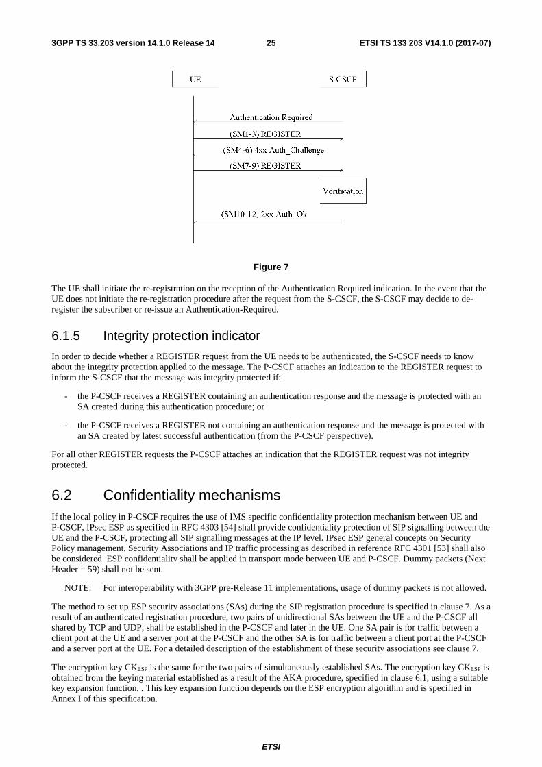
ETSI
ETSI TS 133 203 V14.1.0 (2017-07)253GPP TS 33.203 version 14.1.0 Release 14
Figure 7
The UE shall initiate the re-registration on the reception of the Authentication Required indication. In the event that the UE does not initiate the re-registration procedure after the request from the S-CSCF, the S-CSCF may decide to de-register the subscriber or re-issue an Authentication-Required.
6.1.5 Integrity protection indicator
In order to decide whether a REGISTER request from the UE needs to be authenticated, the S-CSCF needs to know about the integrity protection applied to the message. The P-CSCF attaches an indication to the REGISTER request to inform the S-CSCF that the message was integrity protected if:
- the P-CSCF receives a REGISTER containing an authentication response and the message is protected with an SA created during this authentication procedure; or
- the P-CSCF receives a REGISTER not containing an authentication response and the message is protected with an SA created by latest successful authentication (from the P-CSCF perspective).
For all other REGISTER requests the P-CSCF attaches an indication that the REGISTER request was not integrity protected.
6.2 Confidentiality mechanisms If the local policy in P-CSCF requires the use of IMS specific confidentiality protection mechanism between UE and P-CSCF, IPsec ESP as specified in RFC 4303 [54] shall provide confidentiality protection of SIP signalling between the UE and the P-CSCF, protecting all SIP signalling messages at the IP level. IPsec ESP general concepts on Security Policy management, Security Associations and IP traffic processing as described in reference RFC 4301 [53] shall also be considered. ESP confidentiality shall be applied in transport mode between UE and P-CSCF. Dummy packets (Next Header = 59) shall not be sent.
NOTE: For interoperability with 3GPP pre-Release 11 implementations, usage of dummy packets is not allowed.
The method to set up ESP security associations (SAs) during the SIP registration procedure is specified in clause 7. As a result of an authenticated registration procedure, two pairs of unidirectional SAs between the UE and the P-CSCF all shared by TCP and UDP, shall be established in the P-CSCF and later in the UE. One SA pair is for traffic between a client port at the UE and a server port at the P-CSCF and the other SA is for traffic between a client port at the P-CSCF and a server port at the UE. For a detailed description of the establishment of these security associations see clause 7.
The encryption key CKESP is the same for the two pairs of simultaneously established SAs. The encryption key CKESP is obtained from the keying material established as a result of the AKA procedure, specified in clause 6.1, using a suitable key expansion function. . This key expansion function depends on the ESP encryption algorithm and is specified in Annex I of this specification.

ETSI
ETSI TS 133 203 V14.1.0 (2017-07)263GPP TS 33.203 version 14.1.0 Release 14
The encryption key expansion on the user side is done in the UE. The encryption key expansion on the network side is done in the P-CSCF.
6.3 Integrity mechanisms IPsec ESP as specified in reference RFC 4303 [54] shall provide integrity protection of SIP signalling between the UE and the P-CSCF, protecting all SIP signalling messages at the IP level. IPsec ESP general concepts on Security Policy management, Security Associations and IP traffic processing as described in reference RFC 4301 [53] shall also be considered. ESP integrity shall be applied between UE and P-CSCF either in transport mode if no NAT is present or – if NAT traversal shall be supported – in UDP encapsulated tunnel mode. ESP integrity can be provided by an integrity algorithm or an authenticated encryption algorithm, see IETF RFC 4106 [73].
The method to set up ESP security associations (SAs) during the SIP registration procedure is specified in clause 7. As a result of an authenticated registration procedure, two pairs of unidirectional SAs between the UE and the P-CSCF, all shared by TCP and UDP, shall be established in the P-CSCF and later in the UE. One SA pair is for traffic between a client port at the UE and a server port at the P-CSCF and the other SA is for traffic between a client port at the P-CSCF and a server port at the UE. For a detailed description of the establishment of these security associations see clause 7.
The integrity key IKESP is the same for the two pairs of simultaneously established SAs. The integrity key IKESP is obtained from the keying material established as a result of the AKA procedure, specified in clause 6.1, using a suitable key expansion function. This key expansion function depends on the ESP integrity algorithm and is specified in Annex I of this specification.
The integrity key expansion on the user side is done in the UE. The integrity key expansion on the network side is done in the P-CSCF.
The anti-replay service shall be enabled in the UE and the P-CSCF on all established SAs.
6.4 Hiding mechanisms The Hiding Mechanism is optional for implementation. All I-CSCFs/IBCFs in the HN shall share the same encryption and decryption key Kv. If the mechanism is used and the operator policy states that the topology shall be hidden the I-CSCF/IBCF shall encrypt the hiding information elements when the I-CSCF/IBCF forwards SIP Request or Response messages outside the hiding network’s domain. The hiding information elements are entries in SIP headers, such as Via, Record-Route, Route and Path, which contain addresses of SIP proxies in hiding network. When I-CSCF/IBCF receives a SIP Request or Response message from outside the hiding network’s domain, the I-CSCF/IBCF shall decrypt those information elements that were encrypted by I-CSCF/IBCF in this hiding network domain.
The purpose of encryption in network hiding is to protect the identities of the SIP proxies and the topology of the hiding network. Therefore, an encryption algorithm in confidentiality mode shall be used. The network hiding mechanism will not address the issues of authentication and integrity protection of SIP headers. The AES in CBC mode with 128-bit block and 128-bit key shall be used as the encryption algorithm for network hiding. In the CBC mode under a given key, if a fixed IV is used to encrypt two same plaintexts, then the ciphertext blocks will also be equal. This is undesirable for network hiding. Therefore, random IV shall be used for each encryption. The same IV is required to decrypt the information. The IV shall be included in the same SIP header that includes the encrypted information.
6.5 CSCF interoperating with proxy located in a non-IMS network
SIP signalling protected by TLS specified in RFC 3261 [6] may be used for protecting the SIP interoperation between an IMS CSCF with a proxy/CSCF located in a foreign network. The CSCF may request the TLS connection with a foreign Proxy by publishing sips: URI in DNS server, that can be resolved via NAPTR/SRV mechanism specified in RFC 3263 [23]. When sending/receiving the certificate during the TLS handshaking phase, the CSCF shall verify the name on the certificate against the list of the interworking partners.
The TLS session could be initiated from either network. A TLS connection is capable of carrying multiple SIP dialogs.
Applying this method is to prevent attacks on SIP level, but it does not prohibit other security methods to be applied so as to strengthen the security for IP based networks. This part is specified in Annex A of TS 33.210 [5].

ETSI
ETSI TS 133 203 V14.1.0 (2017-07)273GPP TS 33.203 version 14.1.0 Release 14
NOTE: NOTE 1 in clause 5.1.4 on the use of TLS also applies here.
7 Security association set-up procedure
7.0 General The security association set-up procedure is necessary in order to decide what security services to apply and when the security services start. In the IMS authentication of users is performed during registration as specified in clause 6.1. Subsequent signalling communications in this session will be integrity protected based on the keys derived during the authentication process.
7.1 Security association parameters For protecting IMS signalling between the UE and the P-CSCF it is necessary to agree on shared keys that are provided by IMS AKA, and a set of parameters specific to a protection method. The security mode setup (cf. clause 7.2) is used to negotiate the SA parameters required for IPsec ESP with authentication and confidentiality, in accordance with the provisions in clauses 5.1.3, 5.1.4, 6.2, and 6.3.
The SA parameters that shall be negotiated between UE and P-CSCF in the security mode set-up procedure are:
- Encryption algorithm
Both the UE and the P-CSCF shall adhere to the profiling given in clause 5.3.3 of 33.210 [5] with the addition that only algorithms that can be signalled according to Annex H needs to be supported.
- Integrity algorithm
Both the UE and the P-CSCF shall adhere to the profiling given in clause 5.3.4 of 33.210 [5] with the addition that only algorithms that can be signalled according to Annex H needs to be supported.
NOTE 1: What is called "authentication algorithm" in RFC 4303 [54] is called "integrity algorithm" in this specification in order to be in line with the terminology used in other 3GPP specifications and, in particular, to avoid confusion with the authentication algorithms used in the AKA protocol.
NOTE 2: If one of the two integrity algorithms is compromised then it suffices for the IMS to remain secure that the algorithm is no longer supported by any P-CSCF. The security mode set-up procedure (cf. clause 7.2) will then ensure that some other integrity algorithm is selected.
- SPI (Security Parameter Index)
The SPI is allocated locally for inbound SAs. The triple (SPI, destination IP address, security protocol) uniquely identifies an SA at the IP layer. The UE shall select the SPIs uniquely, and different from any SPIs that might be used in any existing SAs (i.e. inbound and outbound SAs). The SPIs selected by the P-CSCF shall be different than the SPIs sent by the UE, cf. clause 7.2. In an authenticated registration, the UE and the P-CSCF each select two SPIs, not yet associated with existing inbound SAs, for the new inbound security associations at the UE 's client and server ports and the P-CSCF 's client and server ports respectively.
NOTE 3: This allocation of SPIs ensures that protected messages in the uplink always differ from protected messages in the downlink in, at least, the SPI field. This thwarts reflection attacks. When several applications use IPsec on the same physical interface the SIP application should be allocated a separate range of SPIs.
The following SA parameters are not negotiated:
- Life type: the life type is always seconds;
- SA duration: the SA duration has a fixed length of 232-1;
NOTE 4: The SA duration is a network layer concept. From a practical point of view, the value chosen for "SA duration" does not impose any limit on the lifetime of an SA at the network layer. The SA lifetime is controlled by the SIP application as specified in clause 7.4.
ETSI
ETSI TS 133 203 V14.1.0 (2017-07)283GPP TS 33.203 version 14.1.0 Release 14
- Mode: transport mode;
- Key length: the length of the integrity key IKESP depends on the integrity algorithm, c.f. Annex I.
- Key length: the length of the encryption key depends on the encryption algorithm, c.f. Annex I.
Selectors:
The security associations (SA) have to be bound to specific parameters (selectors) of the SIP flows between UE and P-CSCF, i.e. source and destination IP addresses, transport protocols that share the SA, and source and destination ports.
- IP addresses are bound to two pairs of SAs, as in clause 6.3, as follows:
- inbound SA at the P-CSCF: The source and destination IP addresses associated with the SA are identical to those in the header of the IP packet in which the initial SIP REGISTER message was received by the P-CSCF.
- outbound SA at the P-CSCF: the source IP address bound to the outbound SA equals the destination IP address bound to the inbound SA; the destination IP address bound to the outbound SA equals the source IP address bound to the inbound SA.
NOTE 5: This implies that the source and destination IP addresses in the header of the IP packet in which the protected SIP REGISTER message was received by the P-CSCF need to be the same as those in the header of the IP packet in which the initial SIP REGISTER message was received by the P-CSCF.
- The transport protocol selector shall allow UDP and TCP.
- Ports:
1. The P-CSCF associates two ports, called port_ps and port_pc, with each pair of security associations established in an authenticated registration. The ports port_ps and port_pc are different from the standard SIP ports 5060 and 5061. No unprotected messages shall be sent from or received on the ports port_ps and port_pc. From a security point of view, unprotected messages may be received on any port which is different from the ports port_ps and port_pc. The number of the ports port_ps and port_pc are communicated to the UE during the security mode set-up procedure, cf. clause 7.2. These ports are used with both, UDP and TCP. The use of these ports may differ for TCP and UDP, as follows:
UDP case: the P-CSCF receives requests and responses protected with ESP from any UE on the port port_ps (the"protected server port"). The P-CSCF sends requests and responses protected with ESP to a UE on the port port_pc (the "protected client port").
TCP case: the P-CSCF, if it does not have a TCP connection towards the UE yet, shall set up a TCP connection from its port_pc to the port port_us of the UE before sending a request to it..
NOTE 6: Both the UE and the P-CSCF may set up a TCP connection from their client port to the other end's server port on demand. An already existing TCP connection may be reused by both the P-CSCF or the UE; but it is not mandatory.
NOTE 7: The protected server port port_ps stays fixed for a UE until all IMPUs from this UE are de-registered. It may be fixed for a particular P-CSCF over all UEs, but there is no need to fix the same protected server port for different P-CSCFs.
NOTE8: The distinction between the UDP and the TCP case reflects the different behaviour of SIP over UDP and TCP, as specified in section 18 of RFC 3261 [6].
2. The UE associates two ports, called port_us and port_uc, with each pair of security associations established in an authenticated registration. The ports port_us and port_uc are different from the standard SIP ports 5060 and 5061. No unprotected messages shall be sent from or received on the ports port_us and port_uc. From a security point of view, unprotected messages may be received on any port which is different from the ports port_us and port_uc. The number of the ports port_us and port_uc are communicated to the P-CSCF during the security mode set-up procedure, cf. clause 7.2. These ports are used with both, UDP and TCP. The use of these ports may differ for TCP and UDP, as follows:

ETSI
ETSI TS 133 203 V14.1.0 (2017-07)293GPP TS 33.203 version 14.1.0 Release 14
UDP case: the UE receives requests and responses protected with ESP on the port port_us (the"protected server port"). The UE sends requests and responses protected with ESP on the port port_uc (the "protected client port").
TCP case: the UE, if it does not have a TCP connection towards the P-CSCF yet, shall set up a TCP connection to the port port_ps of the P-CSCF before sending a request to it.
NOTE 9: Both the UE and the P-CSCF may set up a TCP connection from their client port to the other end's server port on demand. An already existing TCP connection may be reused by both the P-CSCF or the UE, but it is not mandatory.
NOTE 10: The protected server port port_us stays fixed for a UE until all IMPUs from this UE are de-registered.
NOTE 11: The distinction between the UDP and the TCP case reflects the different behaviour of SIP over UDP and TCP, as specified in section 18 of RFC 3261 [6]
3. The P-CSCF is allowed to receive only REGISTER messages, messages relating to emergency services in accordance with TS 23.167 [31] and TS 24.229 [8], and error messages related to unprotected messages on unprotected ports. All other messages not arriving on a protected port shall be either discarded or rejected by the P-CSCF.
4. The UE is allowed to receive only the following messages on an unprotected port:
- responses to unprotected REGISTER messages;
- messages relating to emergency services in accordance with TS 23.167 [31] and TS 24.229 [8];
- error messages related to unprotected messages.
All other messages not arriving on a protected port shall be rejected or silently discarded by the UE.
The following rules apply:
1. For each unidirectional SA which has been established and has not expired, the SIP application at the P-CSCF stores at least the following data: (UE_IP_address, UE_protected_port, P-CSCF_protected_port, SPI, IMPI, IMPU1, ... , IMPUn, lifetime) in an "SA_table". The pair (UE_protected_port, P-CSCF_protected_port) equals either (port_uc, port_ps) or (port_us, port_pc).
NOTE 12: The SPI is only required when initiating and deleting SAs in the P-CSCF. The SPI is not exchanged between IPsec and the SIP layer for incoming or outgoing SIP messages.
2. The SIP application at the P-CSCF shall check upon receipt of a protected REGISTER message that the source IP address in the packet headers coincide with the UE’s IP address inserted in the Via header of the protected REGISTER message. If the Via header does not explicitly contain the UE's IP address, but rather a symbolic name then the P-CSCF shall first resolve the symbolic name by suitable means to obtain an IP address.
3. The SIP application at the P-CSCF shall check upon receipt of an initial REGISTER message or a re-REGISTER message that the pair (UE_IP_address, UE_protected_client_port), where the UE_IP_address is the source IP address in the packet header and the protected client port is sent as part of the security mode set-up procedure (cf. clause 7.2), has not yet been associated with entries in the "SA_table". Furthermore, the P-CSCF shall check that, for any one IMPI, no more than six SAs per direction are stored at any one time. If these checks are unsuccessful the registration is aborted and a suitable error message is sent to the UE.
NOTE 13: According to clause 7.4 on SA handling, at most six SAs per direction per registered contact may exist at a P-CSCF for one IMPI at any one time.
4. For each incoming protected message the SIP application at the P-CSCF shall verify that the correct inbound SA according to clause 7.4 on SA handling has been used. The SA is identified by the triple (UE_IP_address, UE_protected_port, P-CSCF_protected_port) in the "SA_table". The SIP application at the P-CSCF shall further ensure that the user associated with the SA, which was used to protect the incoming message from the UE, is identical to the user who is associated at SIP level with the message sent by the P-CSCF towards the network.
NOTE 14: Not all SIP messages necessarily contain public or private identities, e.g. subsequent messages in a dialogue. Other information, e.g. a dialogue identifier, may be used to associate the message with a user at SIP level.
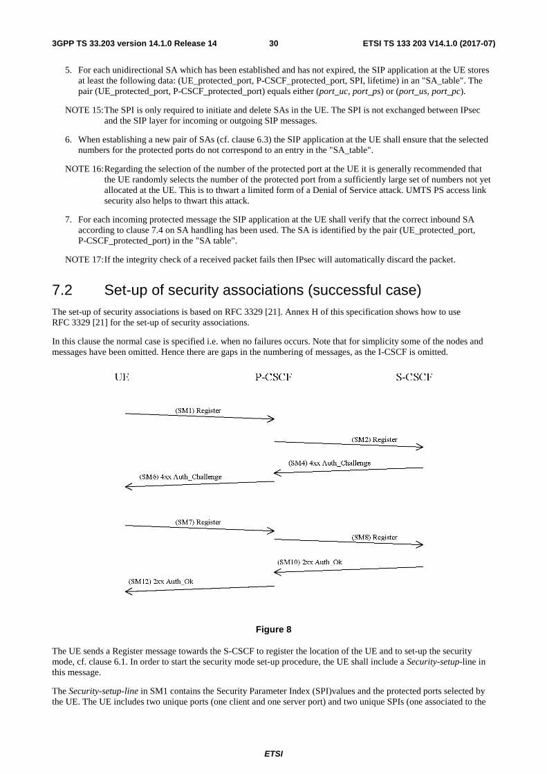
ETSI
ETSI TS 133 203 V14.1.0 (2017-07)303GPP TS 33.203 version 14.1.0 Release 14
5. For each unidirectional SA which has been established and has not expired, the SIP application at the UE stores at least the following data: (UE_protected_port, P-CSCF_protected_port, SPI, lifetime) in an "SA_table". The pair (UE_protected_port, P-CSCF_protected_port) equals either (port_uc, port_ps) or (port_us, port_pc).
NOTE 15: The SPI is only required to initiate and delete SAs in the UE. The SPI is not exchanged between IPsec and the SIP layer for incoming or outgoing SIP messages.
6. When establishing a new pair of SAs (cf. clause 6.3) the SIP application at the UE shall ensure that the selected numbers for the protected ports do not correspond to an entry in the "SA_table".
NOTE 16: Regarding the selection of the number of the protected port at the UE it is generally recommended that the UE randomly selects the number of the protected port from a sufficiently large set of numbers not yet allocated at the UE. This is to thwart a limited form of a Denial of Service attack. UMTS PS access link security also helps to thwart this attack.
7. For each incoming protected message the SIP application at the UE shall verify that the correct inbound SA according to clause 7.4 on SA handling has been used. The SA is identified by the pair (UE_protected_port, P-CSCF_protected_port) in the "SA table".
NOTE 17: If the integrity check of a received packet fails then IPsec will automatically discard the packet.
7.2 Set-up of security associations (successful case) The set-up of security associations is based on RFC 3329 [21]. Annex H of this specification shows how to use RFC 3329 [21] for the set-up of security associations.
In this clause the normal case is specified i.e. when no failures occurs. Note that for simplicity some of the nodes and messages have been omitted. Hence there are gaps in the numbering of messages, as the I-CSCF is omitted.
Figure 8
The UE sends a Register message towards the S-CSCF to register the location of the UE and to set-up the security mode, cf. clause 6.1. In order to start the security mode set-up procedure, the UE shall include a Security-setup-line in this message.
The Security-setup-line in SM1 contains the Security Parameter Index (SPI)values and the protected ports selected by the UE. The UE includes two unique ports (one client and one server port) and two unique SPIs (one associated to the

ETSI
ETSI TS 133 203 V14.1.0 (2017-07)313GPP TS 33.203 version 14.1.0 Release 14
client port, and one associated to the server port) in the REGISTER.It also contains a list of identifiers for the integrity and encryption algorithms, which the UE supports.
SM1: REGISTER(Security-setup = SPI_U, Port_U, UE integrity and encryption algorithms list)
SPI_U is the symbolic name of a pair of SPI values (cf. clause 7.1) (spi_uc, spi_us) that the UE selects. spi_uc is the SPI of the inbound SA at UE’s the protected client port, and spi_us is the SPI of the inbound SA at the UE’s protected server port. The syntax of spi_uc and spi_us are defined in Annex H.
NOTE 1: The syntax defined in Annex H allows a large freedom of number of SPIs. Only one pair of unique SPIs is included in the Security-setup.
Port_U is the symbolic name of a pair of port numbers (port_uc, port_us) as defined in clause 7.1. The syntax of port_uc and port_us is defined in Annex H.
NOTE 2: The syntax defined in Annex H allows a large freedom of number of ports. Only one pair of unique ports is included in the Security-setup.Upon receipt of SM1, the P-CSCF temporarily stores the parameters received in the Security-setup-line together with the UE’s IP address from the source IP address of the IP packet header, the IMPI and IMPU. Upon receipt of SM4, the P-CSCF adds the keys IKIM and CKIM received from the S-CSCF to the temporarily stored parameters.
The P-CSCF then selects the SPIs for the inbound SAs. The P-CSCF shall define the SPIs such that they are unique and different from any SPIs as received in the Security-setup-line from the UE.
NOTE 3: This rule is needed since the UE and the P-CSCF use the same key for inbound and outbound traffic.
In order to determine the integrity and encryption algorithm the P-CSCF proceeds as follows: the P-CSCF has a list of integrity and encryption algorithms it supports, ordered by priority. The P-CSCF selects the first algorithm combination on its own list which is also supported by the UE. If the UE did not include any confidentiality algorithm in SM1 then the P-CSCF shall either select the NULL encryption algorithm or abort the procedure, according to its policy on confidentiality.
NOTE 4: It should be noted that, if the P-CSCF policy requires confidentiality, then all UEs with no encryption support would be denied access to the IMS network. This would apply in particular to UEs, which support only a Release 5-version of this specification or only GIBA according to Annex T of this specification.
The P-CSCF then establishes two new pairs of SAs in the local security association database.
The Security-setup-line in SM6 contains the SPIs and the ports assigned by the P-CSCF. It also contains a list of identifiers for the integrity and encryption algorithms, which the P-CSCF supports. The only exception from this is the case that the P-CSCF is configured to never apply confidentiality. In this case, it shall not include encryption algorithms to the Security-setup-line in SM6.
NOTE 5: The P-CSCF may be configured to never apply confidentiality, e.g. because it trusts the encryption provided by the underlying access network. If the P-CSCF is configured to apply confidentiality whenever the UE supports it then the P-CSCF always includes the encryption algorithms in SM6, which it supports, even if the UE did not include encryption algorithms in SM1. This is to thwart bidding down attacks.
SM6: 4xx Auth_Challenge(Security-setup = SPI_P, Port_P, P-CSCF integrity and encryption algorithms list)
SPI_P is the symbolic name of the pair of SPI values (cf. clause 7.1) (spi_pc, spi_ps) that the P-CSCF selects. spi_pc is the SPI of the inbound SA at the P-CSCF’s protected client port, and spi_ps is the SPI of the inbound SA at the P-CSCF’s protected server port. The syntax of spi_pc and spi_ps is defined in Annex H.
Port_P is the symbolic name of the port numbers (port_pc, port_ps) as defined in clause 7.1. The syntax of Port_P is defined in Annex H.
Upon receipt of SM6, the UE determines the integrity and encryption algorithms as follows: the UE selects the first integrity and encryption algorithm combination on the list received from the P-CSCF in SM 6 which is also supported

ETSI
ETSI TS 133 203 V14.1.0 (2017-07)323GPP TS 33.203 version 14.1.0 Release 14
by the UE. If the P-CSCF did not include any confidentiality algorithm in SM6 then the UE shall select the NULL encryption algorithm.
NOTE 6: Release 5 UE will not support any encryption algorithms, and will choose the first Release 5 integrity algorithm on the list received from the P-CSCF in SM6.
The UE then proceeds to establish two new pairs of SAs in the local SAD.
The UE shall integrity and confidentiality protect SM7 and all following SIP messages. Furthermore the integrity and encryption algorithms list, SPI_P, and Port_P received in SM6, and SPI_U, Port_U sent in SM1 shall be included:
SM7: REGISTER(Security-setup = SPI_U, Port_U, SPI_P, Port_P, P-CSCF integrity and encryption algorithms list)
After receiving SM7 from the UE, the P-CSCF shall check whether the integrity and encryption algorithms list, SPI_P and Port_P received in SM7 is identical with the corresponding parameters sent in SM6. It further checks whether SPI_U and Port_U received in SM7 are identical with those received in SM1. If these checks are not successful the registration procedure is aborted. The P-CSCF shall include in SM8 information to the S-CSCF that the received message from the UE was integrity protected as indicated in clause 6.1.5. The P-CSCF shall add this information to all subsequent REGISTER messages received from the UE that have successfully passed the integrity check in the P-CSCF.
SM8: REGISTER(Integrity-Protection = Successful, IMPI)
The P-CSCF finally sends SM12 to the UE. SM12 does not contain information specific to security mode setup (i.e. a Security-setup line), but with sending SM12 not indicating an error the P-CSCF confirms that security mode setup has been successful. After receiving SM12 not indicating an error, the UE can assume the successful completion of the security-mode setup.
An example of how to make use of two pairs of unidirectional SAs is illustrated in figure 9 with a set of example message exchanges protected by the respective IPsec SAs where the INVITE and following messages are assumed to be carried over TCP.
Register (SM1)
P-CSCFUE
401 Unauthorised (SM6)RAND||AUTN
Register (SM7)RES
OK (SM12)port_uc
port_us
port_ps
port_pc
Invite
200 OK
UnprotectedProtected by SA pair 1Protected by SA pair 2
180 Ringing
Figure 9

ETSI
ETSI TS 133 203 V14.1.0 (2017-07)333GPP TS 33.203 version 14.1.0 Release 14
7.3 Error cases in the set-up of security associations
7.3.1 Error cases related to IMS AKA
7.3.1.0 General
Errors related to IMS AKA failures are specified in clause 6.1. However, this clause additionally describes how these shall be treated, related to security setup.
7.3.1.1 User authentication failure
In this case, SM7 fails integrity check by IPsec at the P-CSCF if the IKIM derived from RAND at UE is wrong. The SIP application at the P-CSCF never receives SM7. It shall delete the temporarily stored SA parameters associated with this registration after a time-out.
In case IKIM was derived correctly, but the response was wrong the authentication of the user fails at the S-CSCF due to an incorrect response. The S-CSCF shall send a 4xx Auth_Failure message to the UE, via the P-CSCF, which may pass through an already established SA. Afterwards, both, the UE and the P-CSCF shall delete the new SAs.
7.3.1.2 Network authentication failure
If the UE is not able to successfully authenticate the network, the UE shall send a REGISTER message which may pass through an already established SA, indicating a network authentication failure, to the P-CSCF. The P-CSCF deletes the new SAs after receiving this message.
7.3.1.3 Synchronisation failure
In this situation, the UE observes that the AUTN sent by the network in SM6 contains an out-of-range sequence number. The UE shall send a REGISTER message to the P-CSCF, which may pass through an already established SA, indicating the synchronization failure. The P-CSCF deletes the new SAs after receiving this message.
7.3.1.4 Incomplete authentication
If the UE responds to an authentication challenge from a S-CSCF, but does not receive a reply before the request times out, the UE shall start a registration procedure if it still requires any IM services. The first message in this registration should be protected with an SA created by a previous successful authentication if one exists.
When the P-CSCF receives a challenge from the S-CSCF and creates the corresponding SAs during a registration procedure, it shall delete any information relating to any previous registration procedure (including the SAs created during the previous registration procedure).
If the P-CSCF deletes a registration SA due to its lifetime being exceeded, the P-CSCF should delete any information relating to the registration procedure that created the SA.
7.3.2 Error cases related to the Security-Set-up
7.3.2.1 Proposal unacceptable to P-CSCF
In this case the P-CSCF cannot accept the proposal set sent by the UE in the Security-Set-up command of SM1. The P-CSCF shall respond to SM1 indicating a failure, by sending an error response to the UE.
7.3.2.2 Proposal unacceptable to UE
If the P-CSCF sends in the security-setup line of SM6 a proposal that is not acceptable for the UE, the UE shall abandon the registration procedure.

ETSI
ETSI TS 133 203 V14.1.0 (2017-07)343GPP TS 33.203 version 14.1.0 Release 14
7.3.2.3 Failed consistency check of Security-Set-up lines at the P-CSCF
The P-CSCF shall check whether authentication and encryption algorithms list received in SM7 is identical with the authentication and encryption algorithms list sent in SM6. If this is not the case the registration procedure is aborted. (Cf. clause 7.2).
7.4 Authenticated re-registration
7.4.0 General
Every registration that includes a user authentication attempt produces new security associations. If the authentication is successful, then these new security associations shall replace the previous ones. This clause describes how the UE and P-CSCF handle this replacement and which SAs to apply to which message.
When security associations are changed in an authenticated re-registration then the protected server ports at the UE (port_us) and the P-CSCF (port_ps) shall remain unchanged, while the protected client ports at the UE (port_uc) and the P-CSCF (port_pc) shall change. For the definition of these ports see clause 7.1.
If the UE has an already active pair of security associations, then it shall use this to protect the REGISTER message. If the S-CSCF is notified by the P-CSCF that the REGISTER message from the UE was integrity-protected it may decide not to authenticate the user by means of the AKA protocol. However, the UE may send unprotected REGISTER messages at any time. In this case, the S-CSCF shall authenticate the user by means of the AKA protocol. In particular, if the UE considers the SAs no longer active at the P-CSCF, e.g., after receiving no response to several protected messages, then the UE should send an unprotected REGISTER message.
Security associations may be unidirectional or bi-directional. This clause assumes that security associations are unidirectional, as this is the general case. For IP layer SAs, the lifetime mentioned in the following clauses is the lifetime held at the application layer. Furthermore deleting an SA means deleting the SA from both the application and IPsec layer. The message numbers, e.g. SM1, used in the following clauses relate to the message flow given in clause 6.1.1.
7.4.1 Void
7.4.1a Management of security associations in the UE
The UE shall be involved in only one registration procedure at a time, i.e. the UE shall remove any data relating to any previous incomplete registrations or authentications, including any SAs created by an incomplete authentication.
The UE may start a registration procedure with two existing pairs of SAs. These will be referred to as the old SAs. The authentication produces two pairs of new SAs. These new SAs shall not be used to protect non-authentication traffic until noted during the authentication flow. In the same way, certain messages in the authentication shall be protected with a particular SA. If the UE receives a message protected with the incorrect SA, it shall discard the message.
A successful authentication proceeds in the following steps:
- The UE sends the SM1 message to register with the IMS. If SM1 was protected, it shall be protected with the old outbound SA.
- The UE receives an authentication challenge in a message (SM6) from the P-CSCF. This message shall be protected with the old inbound SA if SM1 was protected and unprotected otherwise.
- If this message SM6 can be successfully processed by the UE, the UE creates the new SAs, which are derived according to clause 7.1. The lifetime of the new SAs shall be set to allow enough time to complete the registration procedure. The UE then sends its response (SM7) to the P-CSCF, which shall be protected with the new outbound SA. Meanwhile, if SM1 was protected, the UE shall use the old SAs for messages other than those in the authentication, until a successful message of new authentication is received (SM12); if SM1 was unprotected, the UE is not allowed to use IMS service until it receives an authentication successful message (SM12).

ETSI
ETSI TS 133 203 V14.1.0 (2017-07)353GPP TS 33.203 version 14.1.0 Release 14
- The UE receives an authentication successful message (SM12) from the P-CSCF. It shall be protected with the new inbound SA.
- After the successful processing of this message by the UE, the registration is complete. The UE sets the lifetime of the new SAs such that it either equals the latest lifetime of the old SAs or it will expire shortly after the registration timer in the message, depending which gives the SAs the longer life. For further SIP messages sent from UE, the new outbound SAs are used, with the following exception: when a SIP message is part of a pending SIP transaction it may still be sent over the old SA. A SIP transaction is called pending if it was started using an old SA. When a further SIP message protected with a new inbound SA is successfully received from the P-CSCF, then the old SAs shall be deleted as soon as either all pending SIP transactions have been completed, or have timed out. The old SAs shall be always deleted when the lifetime is expired. This completes the SA handling procedure for the UE.
A failure in the authentication can occur for several reasons. If the SM1 was not protected, then no protection shall be applied to the failure messages, except the user authentication failure message which shall be protected with the new SA. If SM1 was protected, the old SAs shall be used to protect the failure messages. In both cases, after processing the failure message, the UE shall delete the new SAs.
The UE shall monitor the expiry time of registrations without an authentication and if necessary increase the lifetime of the SAs created by the last successful authentication such that it will expire shortly after the registration timer in the message.
NOTE: In particular this means that the lifetime of a SA is never decreased.
The UE shall delete any SA whose lifetime is exceeded. The UE shall delete all SAs it holds once all the IMPUs are de-registered.
7.4.2 Void
7.4.2a Management of security associations in the P-CSCF
When the S-CSCF initiates an authentication by sending a challenge to the UE, the P-CSCF may already contain existing SAs from previously completed authentications. It may also contain two existing pairs of SAs from an incomplete authentication. These will be referred to as the old and registration SAs respectively. The authentication produces two pairs of new SAs. These new SAs shall not be used to protect non-authentication traffic until noted during the authentication flow. Similarly certain messages in the authentication shall be protected with a particular SA. If the P-CSCF receives a message protected with the incorrect SA, it shall discard the message.
The P-CSCF associates the IMPI given in the registration procedure and all the successfully registered IMPUs related to that IMPI to an SA.
A successful authentication proceeds in the following steps:
- The P-CSCF receives the SM1 message. If SM1 is protected, it shall be protected with the old inbound SA.
- The P-CSCF forwards the message containing the challenge (SM6) to the UE. This shall be protected with the old outbound SA, if SM1 was protected and unprotected otherwise.
- The P-CSCF then creates the new SAs, which are derived according to clause 7.1. The expiry time of the new SAs shall be set to allow enough time to complete the registration procedure. The registration SAs shall be deleted if they exist.
- The P-CSCF receives the message carrying the response (SM7) from the UE. It shall be protected using the new inbound SA. If SM1 was protected, the old SAs are used to protect messages other than those in the authentication.
- The P-CSCF forwards the successful registration message (SM12) to the UE. It shall be protected using the new outbound SA. This completes the registration procedure for the P-CSCF. The P-CSCF sets the expiry time of the new SAs such that they either equals the latest lifetime of the old SAs or it will expire shortly after the registration timer in the message, depending which gives the SAs the longer life.

ETSI
ETSI TS 133 203 V14.1.0 (2017-07)363GPP TS 33.203 version 14.1.0 Release 14
- After SM12 is sent, the P-CSCF handles the UE related SAs according to following rules:
- If there are old SAs, but SM1 belonging to the same registration procedure was received unprotected, the P-CSCF considers error cases happened, and assumes UE does not have those old SAs for use. In this case the P-CSCF shall remove the old SAs.
- If SM1 belonging to the same registration procedure was protected with an old valid SA, the P-CSCF keeps this inbound SA and the corresponding three SAs created during the same registration with the UE active, and continues to use them. Any other old SAs are deleted. When the old SAs have only a short time left before expiring or a further SIP message protected with a new inbound SA is successfully received from the UE, the P-CSCF starts to use the new SAs for outbound messages with the following exception: when a SIP message is part of a pending SIP transaction it may still be sent over the old SA. A SIP transaction is called pending if it was started using an old SA. The old SAs are then deleted as soon as all pending SIP transactions have been completed, or have timed out. The old SAs are always deleted when the old SAs lifetime are expired. When the old SAs expire without a further SIP message protected by the new SAs, the new SAs are taken into use for outbound messages. This completes the SA handling procedure for the P-CSCF.
A failure in the authentication can occur for several reasons. If the SM1 was not protected, then no protection shall be applied to the failure messages, except the user authentication failure message which shall be protected with the new SAs. If SM1 was protected, the old SAs shall be used to protect the failure messages. In both cases, after processing the failure message, the P-CSCF shall delete the new SAs.
The P-CSCF shall monitor the expiry time of registrations without an authentication and if necessary increase the lifetime of SAs created by the last successful authentication such that it will expire shortly after the registration timer in the message.
The P-CSCF shall delete any SA whose lifetime is exceeded. The P-CSCF shall delete all SAs it holds that are associated with a particular IMPI once all the associated IMPUs are de-registered.
7.5 Rules for security association handling when the UE changes IP address
When a UE changes its IP address, e.g. by using the method described in RFC 3041 [18], then the UE shall delete the existing SA's and initiate an unprotected registration procedure using the new IP address as the source IP address in the packets carrying the REGISTER messages.
8 ISIM
8.0 General For the purposes of this document the ISIM is a term that indicates the collection of IMS security data and functions on a UICC. The following implementation options are permitted:
- Use of a distinct ISIM application on a UICC which does not share security functions with the USIM;
- Use of a distinct ISIM application on a UICC which does share security functions with the USIM;
- Use of a USIM application on a UICC.
NOTE 1: For later releases other implementations of ISIM are foreseen to be permitted.
NOTE 2: The distinction between the terms “ISIM” and “ISIM application” is useful for the purpose of describing the IMS security architecture. However, in other 3GPP specifications these terms are used as synonyms, i.e. the term “ISIM” always refers to the ISIM application in the UICC, as defined in [51]. The case of using a USIM application is always handled separately in other specifications.
If there is an ISIM application and a USIM application on a UICC, then the ISIM application shall always be used for IMS authentication.

ETSI
ETSI TS 133 203 V14.1.0 (2017-07)373GPP TS 33.203 version 14.1.0 Release 14
There shall only be one ISIM for each IMPI. The IMS subscriber shall not be able to modify or enter the IMPI. The IMS subscriber shall not be able to modify or enter the Home Domain Name.
8.1 Requirements on the ISIM application This clause identifies requirements on the ISIM application to support IMS access security. It does not identify any data or functions that may be required on the ISIM application for non-security purposes.
The ISIM application shall include:
- The IMPI;
- At least one IMPU;
- Home Network Domain Name;
- Support for sequence number checking in the context of the IMS Domain;
- The same framework for algorithms as specified for the USIM applies for the ISIM;
- An authentication Key.
The ISIM shall deliver the CK to the UE although it is not required that SIP signalling is confidentiality protected.
At UE power off the existing SAs in the MT shall be deleted. The session keys and related information in the SA shall never be stored on the ISIM.
8.2 Sharing security functions and data with the USIM When an ISIM application is used for IMS access, only the following options for sharing security functions and data are permitted:
- No security functions or data are shared;
- Only the sequence number checking mechanism is shared;
- Only the algorithm is shared;
- Only the algorithm and sequence number checking mechanism are shared;
- The authentication key, authentication functions and the sequence number checking mechanism are shared.
When a USIM is used for IMS access, only the following option is applicable:
- The authentication key, authentication functions and the sequence number checking mechanism are shared.
NOTE: If the authentication keys and functions are shared, the cipher/integrity key sets generated during authentication are used with different cipher/integrity algorithms in CS/PS domain and IMS. Note that the same cipher/integrity key set is never used for both CS/PS domain and IMS because the authentication and key agreement protocol is run independently between CS/PS domain and IMS. Therefore there is no danger that the compromise of the cipher/integrity algorithm in one domain would lead to vulnerabilities in the other domain.
If the mechanism and data for checking sequence numbers are shared then it shall be required for the authentication failure rate due to synchronization failures to be kept sufficiently low. In particular, the mechanism shall be required to support interleaving authentication in three domains (CS, PS and IMS). Example methods to achieve this are described in Annex G.
ETSI
ETSI TS 133 203 V14.1.0 (2017-07)383GPP TS 33.203 version 14.1.0 Release 14
9 IMC This clause identifies requirements on the IMC to support IMS access security. The IMC is used to enable access using IMS AKA. The IMC may be used for IMS access by a non-3GPP-only terminal when specified in the access specific annexes of this specification. The IMC shall not used if ISIM or USIM is present.
NOTE 1: a non-3GPP-only terminal is a terminal that does not support 3GPP access technology.
This clause does not identify any data or functions that may be required on the IMC for non-security purposes. The IMC shall not be part of ISIM, USIM nor SIM.
The IMC shall include:
- The IMPI;
- At least one IMPU;
- Home Network Domain Name;
- Support for sequence number checking in the context of the IMS Domain;
- The same framework for algorithms as specified in TS 33.102 [1];
- An authentication key.

ETSI
ETSI TS 133 203 V14.1.0 (2017-07)393GPP TS 33.203 version 14.1.0 Release 14
Annex A: Void

ETSI
ETSI TS 133 203 V14.1.0 (2017-07)403GPP TS 33.203 version 14.1.0 Release 14
Annex B: Void

ETSI
ETSI TS 133 203 V14.1.0 (2017-07)413GPP TS 33.203 version 14.1.0 Release 14
Annex C: Void

ETSI
ETSI TS 133 203 V14.1.0 (2017-07)423GPP TS 33.203 version 14.1.0 Release 14
Annex D: Void

ETSI
ETSI TS 133 203 V14.1.0 (2017-07)433GPP TS 33.203 version 14.1.0 Release 14
Annex E: Void

ETSI
ETSI TS 133 203 V14.1.0 (2017-07)443GPP TS 33.203 version 14.1.0 Release 14
Annex F: Void

ETSI
ETSI TS 133 203 V14.1.0 (2017-07)453GPP TS 33.203 version 14.1.0 Release 14
Annex G (informative): Management of sequence numbers The example sequence number management schemes in TS 33.102 [1] Informative Annex C can be used to ensure that the authentication failure rate due to synchronization failures to kept sufficiently low when the same sequence number mechanism and data is used for authentication in the PS/CS domains and in the IMS. This can be done by enhancing the method for the allocation of index values in the AuC/HSS so that authentication vectors distributed to different service domains shall always have different index values (i.e. separate ranges of index values are reserved for PS, CS and IMS operation). The AuC/HSS is required to obtain information about which type of service node has requested the authentication vectors. Reallocation of array elements to the IMS domain can be done in the AuC/HSS with no changes required to already deployed USIMs.
As the possibility for out of order use of authentication vectors within the IMS service domain may be quite low, the number of PS or CS array elements that need to be reallocated to the IMS domain could be quite small. This means that the ability to support out of order authentication vectors within the PS and CS domains would not be significantly affected.
Sequence number management is operator specific and for some proprietary schemes over the air updating of the UICC may be needed.

ETSI
ETSI TS 133 203 V14.1.0 (2017-07)463GPP TS 33.203 version 14.1.0 Release 14
Annex H (normative): The use of "Security Mechanism Agreement for SIP Sessions" [21] for security mode set-up The BNF syntax of RFC 3329 [21] is defined for negotiating security associations for semi-manually keyed IPsec or TLS in the following way:
security-client = "Security-Client" HCOLON sec-mechanism *(COMMA sec-mechanism)
security-server = "Security-Server" HCOLON sec-mechanism *(COMMA sec-mechanism)
security-verify = "Security-Verify" HCOLON sec-mechanism *(COMMA sec-mechanism)
sec-mechanism = mechanism-name *(SEMI mech-parameters)
mechanism-name = "ipsec-3gpp" / "tls"
mech-parameters = ( preference / algorithm / protocol / mode / encrypt-algorithm / spi-c / spi-s / port-c / port-s )
preference = "q" EQUAL qvalue
qvalue = ( "0" [ "." 0*3DIGIT ] ) / ( "1" [ "." 0*3("0") ] )
algorithm = "alg" EQUAL ("hmac-sha-1-96" / "aes-gmac" / "null" )
protocol = "prot" EQUAL ( "ah" / "esp" )
mode = "mod" EQUAL ( "trans" / "tun" / "UDP-enc-tun" )
encrypt-algorithm = "ealg" EQUAL ("aes-cbc" / "aes-gcm" / "null" )
spi-c = "spi-c" EQUAL spivalue
spi-s = "spi-s" EQUAL spivalue
spivalue = 10DIGIT; 0 to 4294967295
port-c = "port-c" EQUAL port
port-s = "port-s" EQUAL port
port = 1*DIGIT
The changes compared to RFC 3329 [21] are:
"alg" parameter: Addition of "aes-gmac" and "null". Removal of "hmac-md5-96"
"ealg" parameter: Addition of "aes-cbc" and "aes-gcm". Removal of "des-ede3-cbc"
"mod" parameter: Addition of "UDP-enc-tun"
The use of security association parameters is specified in clauses 7.1, 7.2, M.7.1 and M.7.2 of the present document. The parameters described by the BNF above have the following semantics:
Mechanism-name: For manually keyed IPsec, this field includes the value "ipsec-3gpp". "ipsec-3gpp" mechanism extends the general negotiation procedure of RFC 3329 [21] in the following way:
1 The server shall store the Security-Client header received in the request before sending the response with the Security-Server header.
2 The client shall include the Security-Client header in the first protected request. In other words, the first protected request shall include both Security-Verify and Security-Client header fields.

ETSI
ETSI TS 133 203 V14.1.0 (2017-07)473GPP TS 33.203 version 14.1.0 Release 14
3 The server shall check that the content of Security-Client headers received in previous steps (1 and 2) are the same.
Mech-parameters: Of the mech-parameters, only preference is relevant when the mechanism-name has the value "tls".
Preference: As defined in RFC 3329 [21].
Algorithm: Defines the authentication algorithm. The algorithm parameter is mandatory. The value "aes-gmac" refers to the authentication algorithm ENCR_NULL_AUTH_AES_GMAC defined in IETF RFC 4543 [74]. The value "null" shall only be used with encryption algorithm "aes-gcm".
Protocol: Defines the IPsec protocol. May have a value "ah" or "esp". If no Protocol parameter is present, the value will be "esp".
NOTE 1: According to clause 6 only "esp" (RFC 4303 [54]) is allowed for use in IMS.
Mode: Defines the mode in which the IPsec protocol is used. May have a value "trans" for transport mode, and value "tun" for tunneling mode. If no Mode parameter is present, the value will be "trans".
NOTE 2: Void.
Encrypt-algorithm: If present, defines the encryption algorithm. The value "aes-cbc" refers to the algorithm defined in IETF RFC 3602 [22]. The value "aes-gcm" refers to the encryption algorithm AES-GCM with a 16 octet ICV defined in IETF RFC 4106 [73]. If no Encrypt-algorithm parameter is present, the algorithm will be "null". The value "aes-gcm" shall only be used with authentication algorithm equal to "null".
Spi-c: Defines the SPI number of the inbound SA at the protected client port.
Spi-s: Defines the SPI number of the inbound SA at the protected server port.
Port-c: Defines the protected client port.
Port-s: Defines the protected server port.
It is assumed that the underlying IPsec implementation supports selectors that allow all transport protocols supported by SIP to be protected with a single SA.

ETSI
ETSI TS 133 203 V14.1.0 (2017-07)483GPP TS 33.203 version 14.1.0 Release 14
Annex I (normative): Key expansion functions for IPsec ESP Integrity Keys:
If the selected authentication algorithm is HMAC-SHA-1-96 then IKESP is obtained from IKIM by appending 32 zero bits to the end of IKIM to create a 160-bit string.
If selected authentication algorithm is AES-GMAC as specified in RFC 4543 [74] with 128 bit key then IKESP = IKIM.
The salt value specified in Section 3.2 of RFC 4543 [74] shall be derived using the key derivation function KDF defined in Annex B of TS 33.220 [66]. The input Key to the KDF function shall be equal to the concatenation of CKIM and IKIM: CKIM || IKIM. The input S to the KDF function shall be formed from the following parameters:
- FC = 0x58.
- P0 = "AES_GMAC_SALT" .
- L0 = length of the string “AES_GMAC_SALT” (i.e. 0x00 0x0D).
The salt value shall consist of the 32 least significant bits of the 256 bits of the KDF output.
Encryption Keys:
If selected encryption algorithm is AES-CBC as specified in RFC 3602 [22] with 128 bit key then CKESP = CKIM .
If selected encryption algorithm is AES-GCM as specified in RFC 4106 [73] with 128 bit key then CKESP = CKIM. The salt value specified in Section 4 of RFC 4106 [73] shall be derived using the key derivation function KDF defined in Annex B of TS 33.220 [66]. The input Key to the KDF function shall be equal to the concatenation of CKIM and IKIM: CKIM || IKIM. The input S to the KDF function shall be formed from the following parameters:
- FC = 0x59
- P0 = “AES_GCM_SALT”
- L0 = length of the string “AES_GCM_SALT” (i.e. 0x00 0x0C)
The salt value shall consist of the 32 least significant bits of the 256 bits of the KDF output.

ETSI
ETSI TS 133 203 V14.1.0 (2017-07)493GPP TS 33.203 version 14.1.0 Release 14
Annex J (informative): Recommendations to protect the IMS from UEs bypassing the P-CSCF After the UE does a successful SIP REGISTER with the P-CSCF, malicious UE could try to send SIP messages directly to the S-CSCF. This could imply that the UE would be able to bypass the integrity protection provided by IPsec ESP between the UE and the P-CSCF.
NOTE: The TS 24.229 [8] defines a trust domain that consists of the P-CSCF, the I-CSCF, the S-CSCF, the BGCF, the MGCF, the MRFC and all the AS:s that are not provided by 3rd party service providers. There are nodes in the edge of the trust domain that are allowed to provide with an asserted identity header. The nodes in the trust domain will trust SIP messages with asserted identity headers. The asserted identity information is useful as long as the interfaces in an operator’s network can be trusted.
If a UE manages to bypass the P-CSCF it presents at least the following problems:
1) The P-CSCF is not able to generate any charging information.
2) Malicious UE could masquerade as some other user (e.g. it could potentially send INVITE or BYE messages).
The following recommendations for preventing attacks based on such misbehavior are given:
- Access to S-CSCF entities shall be restricted to the core network entities that are required for IMS operation, only. It shall be ensured that no UE is able to directly send IP packets to IMS-entities other than the required ones, ie. assigned P-CSCF, or HTTP servers.
- Impersonation of IMS core network entities at IP level (IP spoofing), especially impersonation of P-CSCFs by UEs shall be prevented.
- It is desirable to have a general protection mechanism against UEs spoofing (source) IP addresses in any access network providing access to IMS services.
If the traffic is between two non-IMS CSCFs, it is recommended to use TLS mechanisms as specified in RFC 3261 [6]. This will mitigate the problems caused by misbehaviour of the UE. TLS certificate management as outlined in TS 33.310 [24] can be used between two non-IMS CSCFs. If neither intra-CSCF traffic nor CSCF-SEG traffic can be trusted and if this traffic is not protected by the NDS/IP, TS 33.210 [5] mechanisms, then physical protection measures or IP traffic filtering should be applied. This is anyhow not in the scope of 3GPP specification.

ETSI
ETSI TS 133 203 V14.1.0 (2017-07)503GPP TS 33.203 version 14.1.0 Release 14
Annex K: Void

ETSI
ETSI TS 133 203 V14.1.0 (2017-07)513GPP TS 33.203 version 14.1.0 Release 14
Annex L (Normative): Application to fixed broadband access
L.1 Introduction This Annex specifies how the material in the main body and other normative Annexes of the present document apply to the TISPAN NGN (ETSI ES 282 001 [26] ).
NOTE 1: NGN specific abbreviations and terminology can be found in ETSI ES 282 001 [26].
NOTE 2 : In the context of this Annex the term NGN-UE denotes the UE as defined in ETSI ES 282 001 [26]
L.2 Application of clause 4 In 3GPP IMS, the ISIM is mandated to be present on UICC which is usually inserted within the MT component of the UE. In NGN-UEs, the ISIM shall be provided on the UICC, which shall be inserted within either :
1) The TE; or
2) The IMS Residential Gateway (IRG).
NOTE: The exact definition of IRG can be found in ETSI TS 187 003 [57].
Where the TE and IRG each contain an UICC with an ISIM, the ISIM should be used in following order of preference TE, IRG.
UPSF
Home NGN
I-CSCF
Visited NGN
P-CSCF
Generic IP Transport
soft ISIM
NGN-UE
MM IP networks
S-CSCF
1
2
5
3 3
4/5 4/5
UA
GE GE
Figure L.1
Figure L.1 redraws figure 1 of the main body of the present document replacing the 3GPP specific transport domain by Generic IP transport domain. The following observations support figure L.1.
1) The IMS is independent of the transport network
2) Generic Entities (GE) equivalent to the 3GPP transport entities will be present in the Generic IP transport domain.
3) In the NGN architecture the AuC/HSS functionality is performed by the UPSF.
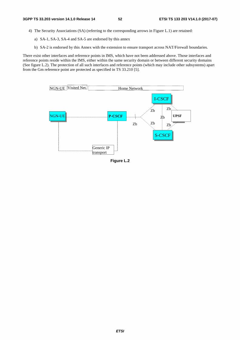
ETSI
ETSI TS 133 203 V14.1.0 (2017-07)523GPP TS 33.203 version 14.1.0 Release 14
4) The Security Associations (SA) (referring to the corresponding arrows in Figure L.1) are retained:
a) SA-1, SA-3, SA-4 and SA-5 are endorsed by this annex
b) SA-2 is endorsed by this Annex with the extension to ensure transport across NAT/Firewall boundaries.
There exist other interfaces and reference points in IMS, which have not been addressed above. Those interfaces and reference points reside within the IMS, either within the same security domain or between different security domains (See figure L.2). The protection of all such interfaces and reference points (which may include other subsystems) apart from the Gm reference point are protected as specified in TS 33.210 [5].
UPE HSS UPSF
Home Network NGN-UE
I-CSCF I-CSCF
S-CSCF S-CSCF
Zb
Zb
Zb
Zb
Zb
Zb
Generic IP transport
P-CSCF NGN-UE
Visited Net.
Figure L.2

ETSI
ETSI TS 133 203 V14.1.0 (2017-07)533GPP TS 33.203 version 14.1.0 Release 14
Annex M (normative): Enhancements to the access security for IP based services to enable NAT traversal for signaling messages
M.0 General NOTE: Annex M.x (x= 1, 2, …) in this annex corresponds to clause x in the body of this specification.
M.1 Scope It is assumed for the purposes of this annex that a NAT device may be located between the UE and the P-CSCF. Only NATs outside the borders of an IMS network are considered, i.e. NATs are assumed to be located at the subscriber's site or in the access network. If there are multiple NATs in either of these locations, it is assumed that their effect sums up in such a way that they can be treated as a single NAT so that the mechanisms described below are still valid.
In this annex enhancements to sections 4 through 8 of this specification are specified that allow a UE and a P-CSCF to detect whether they are located behind a NAT device, to inform each other about their NAT traversal capabilities, and, if there is a NAT present, to securely communicate. If there is no NAT device present, the procedures of sections 6, 7 and 8 apply. Examples of subscribers who are, in general, located behind a NAT device include subscribers accessing IMS via a DSL line.
Furthermore, this specification is restricted to the treatment of NAT traversal for signalling messages. Measures required for NAT traversal of media data are not considered in this specification. The general handling of NAT traversal for signalling messages is specified in TS 23.228 [3] and TS 24.229 [8]. Additional procedures for NAT traversal for protected signalling messages are specified in this specification.
It should be noted that many NAT routers in residential sites do also apply port translation, which is typically denoted as Network Address and Port Translation (NAPT). For reasons of simplicity the term NAT is used, no matter whether only address or address and port translation is actually applied.
NOTE: this annex is fully compliant with RFC 3948 [28], but only partially compliant with RFC 3947 [27] because 3GPP IMS security, as specified in this specification (main body and annexes), does not use IKE as the key management protocol for IPsec.
M.2 References Additional references used in this section were incorporated directly into section 2.
M.3 Definitions, symbols and abbreviations Additional definitions, symbols and abbreviations used in this section were incorporated directly into section 3.
M.4 Overview of the security architecture The text in section 4 applies without changes.
M.5 Security features The text in section 5 applies without changes.

ETSI
ETSI TS 133 203 V14.1.0 (2017-07)543GPP TS 33.203 version 14.1.0 Release 14
M.6 Security mechanisms
M.6.1 Authentication and key agreement The text in section 6.1 applies without changes.
M.6.2 Confidentiality mechanisms If the local policy in P-CSCF requires the use of IMS specific confidentiality protection mechanism between UE and P-CSCF, IPsec ESP as specified in RFC 4303 [54] shall provide confidentiality protection of SIP signalling between the UE and the P-CSCF, protecting all SIP signalling messages at the IP level. IPsec ESP general concepts on Security Policy management, Security Associations and IP traffic processing as described in reference RFC 4301 [53] shall also be considered. ESP confidentiality shall be applied in transport mode between UE and P-CSCF either in transport mode if no NAT is present, or – if NAT traversal shall be supported – in UDP encapsulated tunnel mode. Dummy packets (Next Header = 59) shall not be sent.
NOTE: For interoperability with 3GPP pre-Release 11 implementations, usage of dummy packets is not allowed.
The method to set up ESP security associations (SAs) during the SIP registration procedure is specified in clause M.7. As a result of an authenticated registration procedure, two pairs of unidirectional SAs between the UE and the P-CSCF all shared by TCP and UDP, shall be established in the P-CSCF and later in the UE. One SA pair is for traffic between a client port at the UE and a server port at the P-CSCF and the other SA is for traffic between a client port at the P-CSCF and a server port at the UE. For a detailed description of the establishment of these security associations see clause M.7.
The encryption key CKESP is the same for the two pairs of simultaneously established SAs. The encryption key CKESP is obtained from the key CKIM established as a result of the AKA procedure, specified in clause M.6.1, using a suitable key expansion function.
The encryption key expansion on the user side is done in the UE. The encryption key expansion on the network side is done in the P-CSCF.
M.6.3 Integrity mechanisms IPsec ESP as specified in reference RFC 4303 [54] shall provide integrity protection of SIP signalling between the UE and the P-CSCF, protecting all SIP signalling messages at the IP level. IPsec ESP general concepts on Security Policy management, Security Associations and IP traffic processing as described in reference RFC 4301 [53] shall also be considered. ESP integrity shall be applied between UE and P-CSCF either in transport mode if no NAT is present or – if NAT traversal shall be supported – in UDP encapsulated tunnel mode.
The method to set up ESP security associations (SAs) during the SIP registration procedure is specified in clause M.7. As a result of an authenticated registration procedure, two pairs of unidirectional SAs between the UE and the P-CSCF, all shared by TCP and UDP, shall be established in the P-CSCF and later in the UE. One SA pair is for traffic between a client port at the UE and a server port at the P-CSCF and the other SA is for traffic between a client port at the P-CSCF and a server port at the UE. For a detailed description of the establishment of these security associations see clause M.7.
The integrity key IKESP is the same for the two pairs of simultaneously established SAs. The integrity key IKESP is obtained from the key IKIM established as a result of the AKA procedure, specified in clause M.6.1, using a suitable key expansion function. This key expansion function depends on the ESP integrity algorithm and is specified in Annex I of this specification.
The integrity key expansion on the user side is done in the UE. The integrity key expansion on the network side is done in the P-CSCF.
The anti-replay service shall be enabled in the UE and the P-CSCF on all established SAs.
M.6.4 Hiding mechanisms The text in section 6.4 applies without changes.

ETSI
ETSI TS 133 203 V14.1.0 (2017-07)553GPP TS 33.203 version 14.1.0 Release 14
M.6.5 CSCF interoperating with proxy located in a non-IMS network
The text in section 6.5 applies without changes.
M.7 Security association set-up procedure
M.7.0 General The security association set-up procedure is necessary in order to decide what security services to apply and when the security services start. In the IMS authentication of users is performed during registration as specified in clause M.6.1. Subsequent signalling communications in this session will be integrity protected based on the keys derived during the authentication process.
M.7.1 Security association parameters For protecting IMS signalling between the UE and the P-CSCF it is necessary to agree on shared keys that are provided by IMS AKA, and a set of parameters specific to a protection method. The security mode setup (cf. clause M.7.2) is used to negotiate the SA parameters required for IPsec ESP with authentication and confidentiality, in accordance with the provisions in clauses 5.1.3, 5.1.4, M.6.2, and M.6.3.
The SA parameters that shall be negotiated between UE and P-CSCF in the security mode set-up procedure are:
- Encryption algorithm
cf. clause 7.1
- Integrity algorithm
cf. clause 7.1
- Mode
The IPsec SA mode of operation shall depend on whether the UE is located behind a NAT device or not. If the UE is located behind a NAT device UDP encapsulated tunnel mode according to RFC 3948 [28] shall be used. Otherwise transport mode shall be used. The set-up of security associations (cf. clause M.7.2) allows the P-CSCF to detect whether the UE is located behind a NAT or not.
- SPI (Security Parameter Index)
cf. clause 7.1
The following SA parameters are not negotiated:
cf. clause 7.1
Selectors if no NAT is present:
Cf. section 7.1
Selectors if a NAT is present:
The security associations (SA) have to be bound to specific parameters (selectors) of the SIP flows between UE and P-CSCF, i.e. source and destination IP addresses, transport protocols that share the SA, and source and destination ports.
- IP addresses are bound If a NAT is present, it is assumed that the UE is configured locally with a (e.g. private) IP address. When the UE communicates with the P-CSCF via the NAT device, the NAT allocates a binding, mapping the local IP address to two pairs of SAs, asa publicly routable IP address (called public IP address in the sequel) and
ETSI
ETSI TS 133 203 V14.1.0 (2017-07)563GPP TS 33.203 version 14.1.0 Release 14
perhaps also mapping the source port used in clause 6.3, as follows:the UDP or TCP packet to another port number. In the following, the term UE_IP_address always denotes the public IP address of the UE.
NOTE: The IP addresses and ports used as selectors in IPsec tunnel mode are those of the inner IP header, in accordance with RFC 4301 [53]. The inner IP addresses are always the public IP addresses. Please also note that the terminology used here may differ from that used in other scenarios, e.g. in VPN access to a corporate network, as in the latter scenario the inner IP address is not publicly routable in general.
- IP addresses:
- inbound SA at the P-CSCF: The source and destination IP addresses associated with the SA are identical to those in the header of the IP packet in which the initial SIP REGISTER message was received by the P-CSCF.
- outbound SA at the P-CSCF: the The source IP address bound to the outbound SA equals the destination IP address bound to the inbound SA; the destination IP address bound to the outbound SA equals the source IP address bound to the inbound SA.
NOTE: This implies that the source and destination IP addresses in the header of the inner IP packet in which the protected SIP REGISTER message was received by the P-CSCF need to be the same as those in the header of the IP packet in which the initial SIP REGISTER message was received by the P-CSCF.
NOTE: This further implies that the source address in the inbound SA and the destination address in the outbound SA at the P-CSCF equals the public IP address of the UE.
- outbound SA at the UE: The source IP address bound to the outbound SA equals the public IP address of the UE. The public IP address is learned by the UE from the received parameter in the Via header in the 401 Unauthorized response to the initial unprotected REGISTER Request (cf Section M.7.2). The destination IP address bound to the outbound SA equals the destination IP address in the header of the IP packet in which the initial SIP REGISTER was sent to the P-CSCF.
- inbound SA at the UE: The source IP address bound to the inbound SA equals the destination IP address bound to the outbound SA; the destination IP address bound to the inbound SA equals the source IP address bound to the outbound SA.
NOTE: For the handling of the outer IP header in UDP encapsulated tunnel mode, see section on "Data related to the use of UDP encapsulated tunnel mode" below.
- The transport protocol selector shall allow UDP and TCP.
- Ports:
1. The P-CSCF associates two ports, called port_ps and port_pc, with each pair of security associations established in an authenticated registration. The ports port_ps and port_pc are different from the standard SIP ports 5060 and 5061. No unprotected messages shall be sent from or received on the ports port_ps and port_pc. From a security point of view, unprotected messages may be received on any port which is different from the ports port_ps and port_pc. The number of the ports port_ps and port_pc are communicated to the UE during the security mode set-up procedure, cf. clause 7.2. These ports are used with both, UDP and TCP. The use of these ports may differ for TCP and UDP, as follows:
UDP case: the P-CSCF receives requests and responses protected with ESP from any UE on the port port_ps (the"protected server port"). The P-CSCF sends requests and responses protected with ESP to a UE on the port port_pc (the "protected client port").
TCP case: the P�-CSCF, if it does not have a TCP connection towards the UE yet, shall set up a TCP connection from its port_pc to the port port_us of the UE before sending a request to it..
NOTE: Both the UE and the P-CSCF may set up a TCP connection from their client port to the other end's server port on demand. An already existing TCP connection may be reused by both the P-CSCF or the UE; but it is not mandatory.

ETSI
ETSI TS 133 203 V14.1.0 (2017-07)573GPP TS 33.203 version 14.1.0 Release 14
NOTE: The protected server port port_ps stays fixed for a UE until all IMPUs from this UE are de-registered. It may be fixed for a particular P-CSCF over all UEs, but there is no need to fix the same protected server port for different P-CSCFs.
NOTE: The distinction between the UDP and the TCP case reflects the different behaviour of SIP over UDP and TCP, as specified in section 18 of RFC 3261 [6].
NOTE: The handling of the protected ports is the same, irrespective of whether transport or UDP encapsulated tunnel mode is used.
2. The UE associates two ports, called port_us and port_uc, with each pair of security associations established in an authenticated registration. The ports port_us and port_uc are different from the standard SIP ports 5060 and 5061. No unprotected messages shall be sent from or received on the ports port_us and port_uc. From a security point of view, unprotected messages may be received on any port which is different from the ports port_us and port_uc. The number of the ports port_us and port_uc are communicated to the P-CSCF during the security mode set-up procedure, cf. clause 7.2. These ports are used with both, UDP and TCP. The use of these ports may differ for TCP and UDP, as follows:
UDP case: the UE receives requests and responses protected with ESP on the port port_us (the"protected server port"). The UE sends requests and responses protected with ESP on the port port_uc (the "protected client port").
TCP case: the UE, if it does not have a TCP connection towards the P-CSCF yet, shall set up a TCP connection to the port port_ps of the P-CSCF before sending a request to it.
NOTE: Both the UE and the P-CSCF may set up a TCP connection from their client port to the other end's server port on demand. An already existing TCP connection may be reused by both the P-CSCF or the UE, but it is not mandatory.
NOTE: The protected server port port_us stays fixed for a UE until all IMPUs from this UE are de-registered.
NOTE: The distinction between the UDP and the TCP case reflects the different behaviour of SIP over UDP and TCP, as specified in section 18 of RFC 3261 [6]
NOTE: The handling of the protected ports is the same, irrespective of whether transport or UDP encapsulated tunnel mode is used.
3. The P-CSCF is allowed to receive only REGISTER messages, messages relating to emergency services in accordance with TS 23.167 [31] and TS 24.229 [8], and error messages related to unprotected messages on unprotected ports. All other messages not arriving on a protected port shall be either discarded or rejected by the P-CSCF.
4. The UE is allowed to receive only the following messages on an unprotected port:
- responses to unprotected REGISTER messages;
- messages relating to emergency services in accordance with TS 23.167 [31] and TS 24.229 [8];
- error messages related to unprotected messages.
All other messages not arriving on a protected port shall be rejected or silently discarded by the UE.
Data related to the use of UDP encapsulated tunnel mode
- Tunnel endpoint addresses and header construction for tunnel mode:
In case UDP encapsulated tunnel mode is selected, an "outer" IP header is added to protected packets exchanged between UE and P-CSCF, following the rules of tunnel mode processing according to RFC 4301 53 []. While the IP addresses of the inner IP header are as specified above in the section about "Selectors", the IP addresses of the outer IP header shall be selected as follows:
- P-CSCF: For the outbound SA at the P-CSCF the source address shall be the IP address of the P-CSCF, the destination address shall be the public IP address of the UE. For the inbound SA only the destination address of the outer IP header is used to identify the SA at the P-CSCF, together with the SPI. This address is the IP address of the P-CSCF.

ETSI
ETSI TS 133 203 V14.1.0 (2017-07)583GPP TS 33.203 version 14.1.0 Release 14
- UE: For the outbound SA at the UE the source address shall be the local IP address of the UE, the destination address shall be the address of the P-CSCF as in the destination address of the IP header of the initial unprotected REGISTER message. For the inbound SA only the destination address of the outer IP header is used to identify the SA at the UE. This address is the local IP address of the UE.
Other data of the outer IP header (apart from IP addresses) shall be constructed as specified in RFC 4301 [53].
- Ports used in the encapsulating UDP header:
In case UDP encapsulated tunnel mode is selected, an encapsulating UDP header is inserted after the outer IP header. With respect to the ports used in the UDP header, the following rules shall be applied in accordance with standard IETF RFC 3948 [28]:
- UE: Each protected and UDP encapsulated packet shall use port 4500 as source and destination port in the encapsulating UDP header.
- P-CSCF: When the UE sends an UDP encapsulated packet towards the P-CSCF with the ports as described in the previous paragraph, the NAT will change the source port to a port different from 4500. This port is called port_Uenc. When the P-CSCF receives the first protected and UDP encapsulated message from the UE it shall store port_Uenc (cf. Section 7.2). From then on, all protected UDP encapsulated messages from the P-CSCF to the UE shall use port 4500 as source port and port_Uenc as destination port in the encapsulating UDP header.
The following rules apply:
1. For each unidirectional SA which has been established and has not expired, the SIP application at the P-CSCF stores at least the following data: (UE_IP_address, UE_protected_port, P-CSCF_protected_port, SPI, IMPI, IMPU1, ... , IMPUn, lifetime, mode) in an "SA_table". The pair (UE_protected_port, P-CSCF_protected_port) equals either (port_uc, port_ps) or (port_us, port_pc).
NOTE: The SPI is only required when initiating and deleting SAs in the P-CSCF. The SPI is not exchanged between IPsec and the SIP layer for incoming or outgoing SIP messages.
2. The SIP application at the P-CSCF shall check upon receipt of a protected REGISTER message that the source IP address in the packet headers coincide with the UE’s IP address inserted in the Via header of the protected REGISTER message. If the Via header does not explicitly contain the UE's IP address, but rather a symbolic name then the P-CSCF shall first resolve the symbolic name by suitable means to obtain an IP address.
3. The SIP application at the P-CSCF shall check upon receipt of an initial REGISTER message or a re-REGISTER message that the pair (UE_IP_address, UE_protected_client_port), where the UE_IP_address is the source IP address in the packet header and the protected client port is sent as part of the security mode set-up procedure (cf. clause 7.2), has not yet been associated with entries in the "SA_table". In addition, if the P-CSCF has detected that the UE is located behind a NAT (cf. Section 7.2), the P-CSCF shall check upon receipt of an initial (unprotected) REGISTER message, or a REGISTER message protected with UDP encapsulated tunnel mode, that the pair (UE_IP_address, UE_protected_server_port) has not yet been associated with entries in the "SA_table". Here the UE_IP_address is the source IP address in the packet header, and the protected client and server ports are sent as part of the security mode set-up procedure (cf. clause 7.2).
NOTE: In case of multiple UEs behind the same NAT, the same public IP address may be assigned by the NAT to two different UEs. Therefore, the P-CSCF shall not accept registration attempts from UEs with the same address and protected server port in order to ensure unambiguous addressing of SIP messages sent towards the UE, using the protected server port.
Furthermore, the P-CSCF shall check that, for any one IMPI, no more than six SAs per direction are stored at any one time. If these checks are unsuccessful the registration is aborted and a suitable error message is sent to the UE.
NOTE: According to clause M.7.4 on SA handling, at most six SAs per direction may exist at a P-CSCF for one user at any one time.
4. For each incoming protected message the SIP application at the P-CSCF shall verify that the correct inbound SA according to clause M.7.4 on SA handling has been used. The SA is identified by the triple (UE_IP_address, UE_protected_port, P-CSCF_protected_port) in the "SA_table". The SIP application at the P-CSCF shall further

ETSI
ETSI TS 133 203 V14.1.0 (2017-07)593GPP TS 33.203 version 14.1.0 Release 14
ensure that the user associated with the SA, which was used to protect the incoming message from the UE, is identical to the user who is associated at SIP level with the message sent by the P-CSCF towards the network.
NOTE: Not all SIP messages necessarily contain public or private identities, e.g. subsequent messages in a dialogue. Other information, e.g. a dialogue identifier, may be used to associate the message with a user at SIP level.
5. For each unidirectional SA which has been established and has not expired, the SIP application at the UE stores at least the following data: (UE_IP_address, UE_protected_port, P-CSCF_protected_port, SPI, lifetime, mode) in an "SA_table". The pair (UE_protected_port, P-CSCF_protected_port) equals either (port_uc, port_ps) or (port_us, port_pc).
NOTE: The SPI is only required to initiate and delete SAs in the UE. The SPI is not exchanged between IPsec and the SIP layer for incoming or outgoing SIP messages.
6. When establishing a new pair of SAs (cf. clause 6.3) the SIP application at the UE shall ensure that the selected numbers for the protected ports do not correspond to an entry in the "SA_table". Furthermore, the UE should select port numbers (pseudo-)randomly from a sufficiently large set of numbers not yet allocated at the UE. When the UE receives an error message indicating a collision of a pair (IP address, port), according to rule 3 above, the UE may retry the registration with differently selected port numbers.
NOTE: The UE should select port numbers (pseudo-)randomly for two reasons: 1) to avoid collisions of pairs (IP address, port) at the P-CSCF, cf. rule 3 above. 2) to thwart a limited form of a Denial of Service attack. UMTS/LTE PS access link security also helps to thwart this attack.
NOTE: The (pseudo-)randomization of port numbers is meant for both initial registrations and re-registrations
7. For each incoming protected message the SIP application at the UE shall verify that the correct inbound SA according to clause M.7.4 on SA handling has been used. The SA is identified by the pair (UE_protected_port, P-CSCF_protected_port) in the "SA table".
NOTE: If the integrity check of a received packet fails then IPsec will automatically discard the packet.
M.7.2 Set-up of security associations (successful case) The set-up of security associations is based on RFC 3329 [21]. Annex H of this specification shows how to use RFC 3329 [21] for the set-up of security associations.
In this clause the normal case is specified i.e. when no failures occurs. Note that for simplicity some of the nodes and messages have been omitted. Hence there are gaps in the numbering of messages, as the I-CSCF is omitted.
For the purpose of the description of the message processing in case UDP encapsulated tunnel mode is used, a conceptual functional element called "UDP encapsulation function" is used. The UDP encapsulation function handles all tasks relevant to the UDP encapsulation processing, i.e. the addition and removal of UDP headers to packets. In that sense it does not perform any IPsec processing as such. From an implementation point of view, it is immaterial whether the UDP encapsulation function and the IPsec processing are combined or kept separate. On the network side, the UDP encapsulation function may reside on the P-CSCF or in a separate device.
Relation of this Annex with the NAT traversal functionality specified in TS 24.229 [8]:
If the UE is located behind a NAT, the unprotected REGISTER message and the corresponding unprotected response (messages SM1 and SM6) shall be handled according to Annex F of TS 24.229 [8]. For SIP messages protected with UDP encapsulated tunnel mode, the P-CSCF shall rewrite only the SDP according to Annex F.3 of TS 24.229 [8], and shall not perform the rewriting of the SIP headers specified in Annex F.2 of TS 24.229 [8]. The P-CSCF recognises from the mode parameter in the SA table (cf. section 7.1) that UDP encapsulated tunnel mode is used.

ETSI
ETSI TS 133 203 V14.1.0 (2017-07)603GPP TS 33.203 version 14.1.0 Release 14
Figure M.8
The UE sends a Register message towards the S-CSCF to register the location of the UE and to set-up the security mode, cf. clause M.6.1. In order to start the security mode set-up procedure, the UE shall include a Security-setup-line in this message.
The Security-setup-line in SM1 contains the Security Parameter Index (SPI) values and the protected ports selected by the UE. The UE includes two unique ports (one client and one server port) and two unique SPIs (one associated to the client port, and one associated to the server port) in the REGISTER.It also contains a list of identifiers for the integrity and encryption algorithms, which the UE supports. It shall also contain the list of IPsec modes (i.e. transport and/or UDP encapsulated tunnel mode) supported by the UE.
SM1: REGISTER(Security-setup = SPI_U, Port_U, UE integrity and encryption algorithms list, IPsec mode list)
SPI_U is the symbolic name of a pair of SPI values (cf. clause 7.1) (spi_uc, spi_us) that the UE selects. spi_uc is the SPI of the inbound SA at UE’s the protected client port, and spi_us is the SPI of the inbound SA at the UE’s protected server port. The syntax of spi_uc and spi_us are defined in Annex H.
NOTE 1: The syntax defined in Annex H allows a large freedom of number of SPIs Only one pair of unique SPIs is included in the Security-setup
Port_U is the symbolic name of a pair of port numbers (port_uc, port_us) as defined in clause 7.1. The syntax of port_uc and port_us is defined in Annex H.
NOTE 2: The syntax defined in Annex H allows a large freedom of number of ports. Only one pair of unique ports is included in the Security-setup.
A Release 6 P-CSCF shall propose SA alternatives for Release 5 and Release 6 UE’s since the UE may or may not support confidentiality protection. The P-CSCF then selects the SPIs for the inbound SAs. The same SPI number shall be used for Release 5 and Release 6 options. The P-CSCF shall define the SPIs such that they are unique and different from any SPIs as received in the Security-setup-line from the UE.
Upon receipt of SM1, the P-CSCF temporarily stores the parameters received in the Security-setup-line together with the UE’s IP address from the source IP address of the IP packet header, the IMPI and IMPU.

ETSI
ETSI TS 133 203 V14.1.0 (2017-07)613GPP TS 33.203 version 14.1.0 Release 14
If the source IP address of the IP packet header is different from the address contained in the top-most Via header, the P-CSCF concludes that the UE is located behind a NAT device parameter with the source IP address to the Via header and acts as described in Annex F of TS 24.229 [8]. In this case the P-CSCF concludes that the UE is located behind a NAT device. If the UE has not signalled support for UDP encapsulated tunnel mode in message SM1 the P-CSCF shall silently discard the message and stop performing any further steps.
Otherwise, if the source IP address of SM1 matches the UE address in the Via header, the P-CSCF concludes that the UE is not located behind a NAT. The P-CSCF then continues with the set-up of security associations as specified in section 7.2, otherwise it continues as specified in this annex.
NOTE 3: If the top-most Via header contains a domain name the P-CSCF shall perform the appropriate DNS procedures in order to retrieve the address information to be used for the comparison, as specified in Annex F of TS 24.229 [8].
Upon receipt of SM4, the P-CSCF adds the keys IKIM and CKIM received from the S-CSCF to the temporarily stored parameters.
The P-CSCF then selects the SPIs for the inbound SAs. The P-CSCF shall define the SPIs such that they are unique and different from any SPIs as received in the Security-setup-line from the UE.
NOTE 4: This rule is needed since the UE and the P-CSCF use the same key for inbound and outbound traffic.
In order to determine the integrity and encryption algorithm the P-CSCF proceeds as follows: the P-CSCF has a list of integrity and encryption algorithms it supports, ordered by priority, cf. Annex H. Release 6 algorithms shall have higher priority than Release 5 algorithms.The P-CSCF selects the first algorithm combination on its own list which is also supported by the UE. If the UE did not include any confidentiality algorithm in SM1 then the P-CSCF shall either select the NULL encryption algorithm or abort the procedure, according to its policy on confidentiality.
NOTE 5: It should be noted that, if the P-CSCF policy requires confidentiality, then all UEs with no encryption support would be denied access to the IMS network. This would apply in particular to UEs, which support only a Release 5-version of this specification or only GIBA according to Annex T of this specification.
The P-CSCF then establishes two new pairs of SAs in the local security association database.
In case the P-CSCF has discovered before that the UE is located behind a NAT, it informs the UDP encapsulation function about the IPsec SA data relevant for the UDP encapsulation process. This data consists of the IP source and destination addresses of the outer IP headers and the SPIs used in all four SAs (cf. section M.6.3) established. At this point in time the UDP encapsulation function creates a table, the "UDP encapsulation table", with the following contents:
"UDP Encapsulation Table on the network side "
SA1 SA2 SA3 SA4
Src Addr PCSCF UE_pub PCSCF UE_pub
Dest Addr UE_pub PCSCF UE_pub PCSCF
Src Port 4500 undef 4500 undef
Dest Port undef 4500 undef 4500
SPI SPI_us SPI_ps SPI_uc SPI_pc
The P-CSCF shall use port 4500 as the source port for UDP encapsulated packets towards the UE. The P-CSCF will also receive packets from the UE with and as the destination port 4500. This is the IPsec standard port for UDP encpasulated IPsec packets (see RFC 3948 [28]). The source port for packets received by the P-CSCF from the UE and the destination port for packets sent by the P-CSCF towards the UE is not known yet and can only be learned in a later step (see below).
NOTE 6: A corresponding table on the UE side is not required as the ports used by the UE are not affected by the NAT.
The Security-setup-line in SM6 contains the SPIs and the ports assigned by the P-CSCF. It also contains a list of identifiers for the integrity and encryption algorithms, which the P-CSCF supports. The only exception from this is the

ETSI
ETSI TS 133 203 V14.1.0 (2017-07)623GPP TS 33.203 version 14.1.0 Release 14
case that the P-CSCF is configured to never apply confidentiality. In this case, it shall not include encryption algorithms to the Security-setup-line in SM6.
Furthermore, the P-CSCF indicates the IPsec mode of operation. In case the P-CSCF detected that the UE is behind a NAT, it indicates UDP encapsulated tunnel mode, otherwise transport mode is indicated.
NOTE 7: The P-CSCF may be configured to never apply confidentiality, e.g. because it trusts on the encryption provided by the underlying access network. In this case, the P-CSCF acts according to Release 5 specifications, and does not include encryption algorithms to the Security-setup-line in SM6. If the P-CSCF is configured to apply confidentiality whenever the UE supports it then the P-CSCF always includes the encryption algorithms in SM6, which it supports, even if the UE did not include encryption algorithms in SM1. This is to thwart bidding down attacks.P-CSCF may be configured to trust on the encryption provided by the underlying access network. In this case, the P-CSCF acts according to Release 5 specifications, and does not include encryption algorithms to the Security-setup-line in SM6.
SM6: 4xx Auth_Challenge(Security-setup = SPI_P, Port_P, P-CSCF integrity and encryption algorithms list), IPsec mode )
SPI_P is the symbolic name of the pair of SPI values (cf. clause 7.1) (spi_pc, spi_ps) that the P-CSCF selects. spi_pc is the SPI of the inbound SA at the P-CSCF’s protected client port, and spi_ps is the SPI of the inbound SA at the P-CSCF’s protected server port. The syntax of spi_pc and spi_ps is defined in Annex H.
Port_P is the symbolic name of the port numbers (port_pc, port_ps) as defined in clause 7.1. The syntax of Port_P is defined in Annex H.
Upon receipt of SM6, the UE determines the integrity and encryption algorithms as follows: the UE selects the first integrity and encryption algorithm combination on the list received from the P-CSCF in SM 6 which is also supported by the UE.
NOTE 8: Release 5 UE will not support any encryption algorithms, and will choose the first Release 5 integrity algorithm on the list received from the P-CSCF in SM6.
The UE shall either configure UDP encapsulated tunnel mode or determine the IPsec mode according to the mode information contained in SM6. If no mode information is included in SM6, the UE shall first check whether it is located behind a NAT by checking for the presence of a "received"-parameter in the Via header of SM6. If the UE is not located behind a NAT, the UE assumes transport mode, otherwise it aborts the communication. If transport mode is used the UE continues with the set-up of security associations as specified in section 7.2, otherwise it continues as specified in this annex.
The UE then proceeds to establish two new pairs of SAs in the local SAD.
The UE shall integrity and confidentiality protect SM7 and all following SIP messages.
Furthermore the integrity and encryption algorithms list, SPI_P, and Port_P received in SM6, and SPI_U, Port_U sent in SM1 shall be included:
SM7: REGISTER(Security-setup = SPI_U, Port_U, SPI_P, Port_P, P-CSCF integrity and encryption algorithms list)
If UDP encapsulated tunnel mode is used, the UE shall use the following addresses and ports in the various headers of message SM7:
SIP header: In the Via and Contact header the UE shall use its public IP address and protected server port. The UE learns its public IP address by inspecting the received parameter in the top-most Via header included in message SM6, in case such a parameter is present.
IP and UDP/TCP headers are used as specified in M.7.1.
If UDP encapsulated tunnel mode is applied, the UE shall start sending keep alive messages according to RFC 3948 [28]. This ensures that the NAT binding is kept alive for the duration of the registration.

ETSI
ETSI TS 133 203 V14.1.0 (2017-07)633GPP TS 33.203 version 14.1.0 Release 14
When SM 7 arrives at the P-CSCF it is at first processed by the UDP encapsulation function. The UDP encapsulation function can now learn port_Uenc, which the NAT has chosen for the UDP encapsulated packet. The UDP encapsulation function inserts this port in the UDP encapsulation table, so that the table is complete.
"UDP Encapsulation Table" on the network side
SA1 SA2 SA3 SA4
Src Addr PCSCF UE_pub PCSCF UE_pub
Dest Addr UE_pub PCSCF UE_pub PCSCF
Src Port 4500 Port_Uenc 4500 Port_Uenc
Dest Port Port_Uenc 4500 Port_Uenc 4500
SPI SPI_us SPI_ps SPI_uc SPI_pc
The UDP encapsulation function removes the UDP header from the IP packet and hands it over to the IPsec processing.
After successful IPsec processing the SIP application in the P-CSCF shall check whether the integrity algorithms list, SPI_P and Port_P received in SM7 is identical with the corresponding parameters sent in SM6. It further checks whether SPI_U and Port_U received in SM7 are identical with those received in SM1. If these checks are not successful the registration procedure is aborted.
The P-CSCF shall include in SM8 information to the S-CSCF that the received message from the UE was integrity protected as indicated in clause 6.1.5. The P-CSCF shall add this information to all subsequent REGISTER messages received from the UE that have successfully passed the integrity check in the P-CSCF.
SM8: REGISTER(Integrity-Protection = Successful, IMPI)
The P-CSCF finally sends SM12 to the UE. SM12 does not contain information specific to security mode setup (i.e. a Security-setup line), but with sending SM12 not indicating an error the P-CSCF confirms that security mode setup has been successful.
After receiving SM12 not indicating an error, the UE can assume the successful completion of the security-mode setup.
An example of how to make use of two pairs of unidirectional SAs is illustrated in figure M.9 with a set of example message exchanges protected by the respective IPsec SAs where the INVITE and following messages are assumed to be carried over TCP.
Register (SM1)
P-CSCFUE
401 Unauthorised (SM6)RAND||AUTN
Register (SM7)RES
OK (SM12)port_uc
port_us
port_ps
port_pc
Invite
200 OK
UnprotectedProtected by SA pair 1Protected by SA pair 2
180 Ringing
Figure M.9

ETSI
ETSI TS 133 203 V14.1.0 (2017-07)643GPP TS 33.203 version 14.1.0 Release 14
M.7.3 Error cases in the set-up of security associations
M.7.3.1 Error cases related to IMS AKA
The text in clause 7.3.1 applies without changes.
M.7.3.2 Error cases related to the Security-Set-up
M.7.3.2.1 Proposal unacceptable to P-CSCF
In this case the P-CSCF cannot accept the proposal set sent by the UE in the Security-Set-up command of SM1. The P-CSCF shall respond to SM1 indicating a failure, by sending an error response to the UE.
M.7.3.2.2 Proposal unacceptable to UE
If the P-CSCF sends in the security-setup line of SM6 a proposal that is not acceptable for the UE, the UE shall abandon the registration procedure.
M.7.3.2.3 Failed consistency check of Security-Set-up lines at the P-CSCF
The P-CSCF shall check whether authentication and encryption algorithms list received in SM7 is identical with the authentication and encryption algorithms list sent in SM6. If this is not the case the registration procedure is aborted. (Cf. clause 7.2).
M.7.3.2.4 Missing NAT traversal capabilities in the presence of a NAT
In case the P-CSCF detects the presence of a NAT, but the UE or the P-CSCF do not support NAT traversal as specified in this annex, the P-CSCF shall abort the procedure.
M.7.4 Authenticated re-registration
M.7.4.0 General
Every registration that includes a user authentication attempt produces new security associations. If the authentication is successful, then these new security associations shall replace the previous ones. This clause describes how the UE and P-CSCF handle this replacement and which SAs to apply to which message.
When security associations are changed in an authenticated re-registration then the protected server ports at the UE (port_us) and the P-CSCF (port_ps) shall remain unchanged, while the protected client ports at the UE (port_uc) and the P-CSCF (port_pc) shall change. For the definition of these ports see clause 7.1.
If the UE has an already active pair of security associations, then it shall use this to protect the REGISTER message. If the S-CSCF is notified by the P-CSCF that the REGISTER message from the UE was integrity-protected it may decide not to authenticate the user by means of the AKA protocol. However, the UE may send unprotected REGISTER messages at any time. In this case, the S-CSCF shall authenticate the user by means of the AKA protocol. In particular, if the UE considers the SAs no longer active at the P-CSCF, e.g., after receiving no response to several protected messages, then the UE should send an unprotected REGISTER message.
Security associations may be unidirectional or bi-directional. This clause assumes that security associations are unidirectional, as this is the general case. For IP layer SAs, the lifetime mentioned in the following clauses is the lifetime held at the application layer. Furthermore deleting an SA means deleting the SA from both the application and IPsec layer. The message numbers, e.g. SM1, used in the following clauses relate to the message flow given in clause 6.1.1.
ETSI
ETSI TS 133 203 V14.1.0 (2017-07)653GPP TS 33.203 version 14.1.0 Release 14
M.7.4.1 Void
M.7.4.1a Management of security associations in the UE
The UE shall be involved in only one registration procedure at a time, i.e. the UE shall remove any data relating to any previous incomplete registrations or authentications, including any SAs created by an incomplete authentication.
The UE may start a registration procedure with two existing pairs of SAs. These will be referred to as the old SAs. The authentication produces two pairs of new SAs. These new SAs shall not be used to protect non-authentication traffic until noted during the authentication flow. In the same way, certain messages in the authentication shall be protected with a particular SA. If the UE receives a message protected with the incorrect SA, it shall discard the message.
A successful authentication proceeds in the following steps:
- The UE sends the SM1 message to register with the IMS. If SM1 was protected, it shall be protected with the old outbound SA.
- The UE receives an authentication challenge in a message (SM6) from the P-CSCF. This message shall be protected with the old inbound SA if SM1 was protected and unprotected otherwise.
- If this message SM6 can be successfully processed by the UE, the UE creates the new SAs, which are derived according to clause 7.1. The lifetime of the new SAs shall be set to allow enough time to complete the registration procedure. If SM1 was protected and UDP encapsulated tunnel mode is used in the old SAs, the new SAs shall also be configured in with UDP encapsulated tunnel mode. The UE then sends its response (SM7) to the P-CSCF, which shall be protected with the new outbound SA. Meanwhile, if SM1 was protected, the UE shall use the old SAs for messages other than those in the authentication, until a successful message of new authentication is received (SM12); if SM1 was unprotected, the UE is not allowed to use IMS service until it receives an authentication successful message (SM12).
- The UE receives an authentication successful message (SM12) from the P-CSCF. It shall be protected with the new inbound SA.
- After the successful processing of this message by the UE, the registration is complete. The UE sets the lifetime of the new SAs such that it either equals the latest lifetime of the old SAs or it will expire shortly after the registration timer in the message, depending which gives the SAs the longer life. For further SIP messages sent from UE, the new outbound SAs are used, with the following exception: when a SIP message is part of a pending SIP transaction it may still be sent over the old SA. A SIP transaction is called pending if it was started using an old SA. When a further SIP message protected with a new inbound SA is successfully received from the P-CSCF, then the old SAs shall be deleted as soon as either all pending SIP transactions have been completed, or have timed out. The old SAs shall be always deleted when the lifetime is expired. This completes the SA handling procedure for the UE.
A failure in the authentication can occur for several reasons. If the SM1 was not protected, then no protection shall be applied to the failure messages, except the user authentication failure message which shall be protected with the new SA. If SM1 was protected, the old SAs shall be used to protect the failure messages. In both cases, after processing the failure message, the UE shall delete the new SAs.
The UE shall monitor the expiry time of registrations without an authentication and if necessary increase the lifetime of the SAs created by the last successful authentication such that it will expire shortly after the registration timer in the message.
NOTE: In particular this means that the lifetime of a SA is never decreased.
The UE shall delete any SA whose lifetime is exceeded. The UE shall delete all SAs it holds once all the IMPUs are de-registered.
M.7.4.2 Void
M.7.4.2a Management of security associations in the P-CSCF
When the S-CSCF initiates an authentication by sending a challenge to the UE, the P-CSCF may already contain existing SAs from previously completed authentications. It may also contain two existing pairs of SAs from an
ETSI
ETSI TS 133 203 V14.1.0 (2017-07)663GPP TS 33.203 version 14.1.0 Release 14
incomplete authentication. These will be referred to as the old and registration SAs respectively. The authentication produces two pairs of new SAs. These new SAs shall not be used to protect non-authentication traffic until noted during the authentication flow. Similarly certain messages in the authentication shall be protected with a particular SA. If the P-CSCF receives a message protected with the incorrect SA, it shall discard the message.
The P-CSCF associates the IMPI given in the registration procedure and all the successfully registered IMPUs related to that IMPI to an SA.
A successful authentication proceeds in the following steps:
- The P-CSCF receives the SM1 message. If SM1 is protected, it shall be protected with the old inbound SA.
- The P-CSCF forwards the message containing the challenge (SM6) to the UE. This shall be protected with the old outbound SA, if SM1 was protected and unprotected otherwise.
- The P-CSCF then creates the new SAs, which are derived according to clause 7.1. The expiry time of the new SAs shall be set to allow enough time to complete the registration procedure. If SM1 was protected and UDP encapsulated tunnel mode is used in the old SAs, the new SAs shall also be configured with UDP encapsulated tunnel mode. The registration SAs shall be deleted if they exist.
- The P-CSCF receives the message carrying the response (SM7) from the UE. It shall be protected using the new inbound SA. If SM1 was protected, the old SAs are used to protect messages other than those in the authentication.
- The P-CSCF forwards the successful registration message (SM12) to the UE. It shall be protected using the new outbound SA. This completes the registration procedure for the P-CSCF. The P-CSCF sets the expiry time of the new SAs such that they either equals the latest lifetime of the old SAs or it will expire shortly after the registration timer in the message, depending which gives the SAs the longer life.
- After SM12 is sent, the P-CSCF handles the UE related SAs according to following rules:
- If there are old SAs, but SM1 belonging to the same registration procedure was received unprotected, the P-CSCF considers error cases happened, and assumes UE does not have those old SAs for use. In this case the P-CSCF shall remove the old SAs.
- If SM1 belonging to the same registration procedure was protected with an old valid SA, the P-CSCF keeps this inbound SA and the corresponding three SAs created during the same registration with the UE active, and continues to use them. Any other old SAs are deleted. When the old SAs have only a short time left before expiring or a further SIP message protected with a new inbound SA is successfully received from the UE, the P-CSCF starts to use the new SAs for outbound messages with the following exception: when a SIP message is part of a pending SIP transaction it may still be sent over the old SA. A SIP transaction is called pending if it was started using an old SA. The old SAs are then deleted as soon as all pending SIP transactions have been completed, or have timed out. The old SAs are always deleted when the old SAs lifetime are expired. When the old SAs expire without a further SIP message protected by the new SAs, the new SAs are taken into use for outbound messages. This completes the SA handling procedure for the P-CSCF.
A failure in the authentication can occur for several reasons. If the SM1 was not protected, then no protection shall be applied to the failure messages, except the user authentication failure message which shall be protected with the new SAs. If SM1 was protected, the old SAs shall be used to protect the failure messages. In both cases, after processing the failure message, the P-CSCF shall delete the new SAs.
The P-CSCF shall monitor the expiry time of registrations without an authentication and if necessary increase the lifetime of SAs created by the last successful authentication such that it will expire shortly after the registration timer in the message.
The P-CSCF shall delete any SA whose lifetime is exceeded. The P-CSCF shall delete all SAs it holds that are associated with a particular IMPI once all the associated IMPUs are de-registered.
M.7.5 Rules for security association handling when the UE changes IP address
The text in clause 7.5 applies without changes.

ETSI
ETSI TS 133 203 V14.1.0 (2017-07)673GPP TS 33.203 version 14.1.0 Release 14
M.8 ISIM The text in clause 8 applies without changes.
M.9 IMC The text in clause 9 applies without changes.

ETSI
ETSI TS 133 203 V14.1.0 (2017-07)683GPP TS 33.203 version 14.1.0 Release 14
Annex N (normative): Enhancements to the access security to enable SIP Digest
N.1 SIP Digest SIP Digest authentication and the requirements in this Annex shall not apply to access networks defined in 3GPP specifications. The P-CSCF can enforce this condition by identifying REGISTER requests relating to SIP Digest according to the rules in Annex P.3 of the present document and discarding them when received over an access network defined in 3GPP specifications.
The provisions in Annex N are optional for implementation. The provisions in Annex N are optional for use. However, the use of one of the authentication mechanisms in the present document is mandated.
SIP Digest shall not be used in conjunction with IPsec.
NOTE 1: The use of SIP Digest in conjunction with IPsec, as specified in the main body and in Annex N of this specification, is technically impossible because SIP Digest does not generate session keys for use with IPsec security associations.
An additional scheme for authentication is SIP Digest as specified in RFC 3261 [6]. SIP Digest achieves mutual authentication between the UE and the HN, and is based on HTTP Digest as specified in RFC 2617 [12]. The identity used for authenticating a subscriber is the private identity, IMPI, which has the form of a NAI. The HSS and the UE share a preset secret (e.g., a password) associated with the IMPI. The generation of the authentication challenge shall be done in the same way as specified in RFC 2617 [12] and the present document.
It is the policy of the HN that decides if an authentication shall take place for the registration of an additional IMPU that is not part of the already registered set of IMPUs associated with the same IMPI.
If a UE supports SIP Digest as well as further authentication methods, the UE shall proceed as follows:
- If the access network is of a type defined in 3GPP specifications then the UE shall not select SIP Digest, in accordance with the requirement at the start of this clause.
NOTE 2: The rules listed in Annex T of this specification say how a UE can select between IMS AKA and GIBA.
- If the access network is of a type not defined in 3GPP specifications then
- if both the UE and network support IMS AKA according to the main body or Annex M of this specification, as determined by the use of sip-sec-agree RFC 3329 [21], the authentication method shall be IMS AKA;
- otherwise the authentication method shall be SIP Digest as specified in Annex N of this specification.
N.2 Authentication
N.2.1 Authentication Requirements
N.2.1.1 Authentication Requirements for Registrations
For the purposes of this subclause, the name "authentication" is used synonymously with "entity authentication".
Before a user can get access to the IM services at least one IMPU needs to be registered and the IMPI authenticated in the IMS at application level. In order to get registered the UE sends a SIP REGISTER message towards the SIP registrar, i.e. the S-CSCF, cf. figure N.1, which will perform the authentication of the user. The message flows are the same regardless of whether the user has an IMPU already registered or not.

ETSI
ETSI TS 133 203 V14.1.0 (2017-07)693GPP TS 33.203 version 14.1.0 Release 14
Figure N.1: The IMS Authentication using SIP Digest for an unregistered IM subscriber and successful mutual authentication
The detailed registration procedures are defined in TS 24.229 [8].
The NAT traversal procedures in RFC 5626 [32] and in TS 24.229 [8] clause K.4 shall apply.
NOTE 1: It is recognized that RFC 5626 [32] can be useful for capabilities beyond NAT traversal (e.g. multiple registrations) however this annex does not consider such capabilities at this time.
The UE should include an indication of support for managing client-initiated connections as defined in RFC 5626 [32] in all REGISTER requests. Per RFC 5626 [32], the P-CSCF shall be able to accept registration request with or without an indication of support for managing client-initiated connections. However, the P-CSCF should only accept a register request without support for managing client-initiated connections if it can determine that no NAT is present in the signaling path between the UE and the P-CSCF.
NOTE 2: It is left to stage 3 specifications how a P-CSCF can determine whether the conditions in the preceding paragraph are met. An operator may configure all UEs and P-CSCFs in his network not to use support for managing client-initiated connections (provided there is no roaming). Cf. also the implications of the indication of support for managing client-initiated connections for the P-CSCF procedures after receiving SM11.
SMn stands for SIP Message n and CMm stands for Cx message m which has a relation to the authentication process:
SM1: REGISTER(IMPI*, IMPU)
“IMPI*” in SM1 means that the inclusion of the IMPI is optional in SM1.
NOTE 2a: When a registering UE omits the IMPI from the REGISTER request, the IMPI for the registration is derived from the registering IMPU. Since there can be only one registered instance of an IMPI at any point in time, the registering IMPU in this case cannot be shared across multiple UEs.
In SM2 and SM3 the P-CSCF and the I-CSCF respectively forwards the SIP REGISTER towards the S-CSCF. If SM1 does not contain an IMPI, the P-CSCF shall behave according to Annex P.3 and forward the message as SM2 to the I-CSCF.
NOTE 2b: Annex P.3 formulates conditions depending on the presence of an Authorization header. Note that, if SM1 does not contain an IMPI, then SM1 does not contain an Authorization header.

ETSI
ETSI TS 133 203 V14.1.0 (2017-07)703GPP TS 33.203 version 14.1.0 Release 14
The I-CSCF queries the HSS to find the address of the S-CSCF. If SM2 does not contain an IMPI the I-CSCF shall derive the IMPI from the IMPU in the REGISTER request as described in 3GPP TS 24.229 [8]. Then the I-CSCF forwards the message as SM3 to the S-CSCF.
After receiving SM3, if the IMPU is not currently registered at the S-CSCF, the S-CSCF needs to set the registration flag at the HSS to initial registration pending. This is done in order to handle UE terminated calls while the initial registration is in progress and not successfully completed. The registration flag is stored in the HSS together with the S-CSCF name and user identity, and is used to indicate whether a particular IMPU of the user is unregistered or registered at a particular S-CSCF or if the initial registration at a particular S-CSCF is pending. The registration flag is set by the S-CSCF sending a Cx-Put to the HSS. If the IMPU is currently registered, the S-CSCF shall leave the registration flag set to registered. At this stage the HSS has performed a check that the IMPI and the IMPU belong to the same user.
The S-CSCF shall determine the type of authentication based on the rules in Annex P. If SM3 does not contain an IMPI the S-CSCF shall derive the IMPI from the IMPU in the REGISTER request as described in 3GPP TS 24.229 [8]. If the IMS registration request is related to SIP Digest, then the procedures below apply.
Upon receiving the SIP REGISTER the S-CSCF shall use a SIP Digest Authentication Vector (SD-AV) for authenticating the user. If the S-CSCF has no valid SD-AV for the specific IMPI, then the S-CSCF shall send a request for SD-AV(s) to the HSS in CM1 where the number m of SD-AVs wanted is equal to 1.
CM1: Cx-AV-Req(IMPI, m)
Upon receipt of a request from the S-CSCF, the HSS sends one SD-AV to the S-CSCF using CM2. The SD-AV consists of the qop (quality of protection) value, the authentication algorithm, realm, and a hash, called H(A1), of the IMPI, realm, and password. Refer to RFC 2617 [12] for additional information on the values in the authentication vector for SIP Digest based authentication.
The qop value shall be set to "auth" since SIP Digest, as used in IMS, can only provide authentication, not message integrity.
CM2: Cx-AV-Req-Resp(IMPI, realm, algorithm, qop, H(A1) )
The S-CSCF generates a random nonce, stores H(A1) and the nonce against the IMPI, and then sends a SIP 401 Auth_Challenge i.e., an authentication challenge towards the UE including the nonce in SM4. It also includes the realm, qop and algorithm parameters. RFC 2617 [12] specifies how to populate the parameters of a 401 Auth_Challenge.
SM4: 401 Auth_Challenge(IMPI, realm, nonce, qop, algorithm)
The I-CSCF forwards the SIP 4xx Auth_Challenge message towards the P-CSCF as SM5.
When the P-CSCF receives SM5 it shall forward the message to the UE.
SM6: 401 Auth_Challenge(IMPI, realm, nonce, qop, algorithm)
Upon receiving the challenge, SM6, the UE generates a cnonce. It then uses the cnonce as well as parameters provided in the SM6 such as nonce and qop to calculate an authentication response according to RFC 2617 [12]. This response and other parameters are put into the Authorization header and sent back towards the network in SM7. The inclusion of the IMPI and an Authorization header in SM7 are mandatory.
SM7: REGISTER(IMPI, realm, nonce, response, cnonce, qop, nonce-count, algorithm, digest-uri)

ETSI
ETSI TS 133 203 V14.1.0 (2017-07)713GPP TS 33.203 version 14.1.0 Release 14
NOTE 3: As specified in RFC 3261 [6], when the P-CSCF receives a SIP request from the UE, the P-CSCF checks the IP address in the "sent-by" parameter of the Via header field provided by the UE. If the "sent-by" parameter contains a domain name, or if it contains an IP address that differs from the packet source IP address, the P-CSCF adds a "received" parameter to that Via header field value. This parameter contains the source IP address from which the packet was received.
The P-CSCF forwards the authentication response in SM8 to the I-CSCF, which queries the HSS to find the address of the S-CSCF. In SM9 the I-CSCF forwards the authentication response to the S-CSCF.
Upon receiving SM9 containing the response, the S-CSCF calculates the expected response using the previously stored H(A1) and stored nonce together with other parameters contained in SM9 (e.g., cnonce, nonce-count, qop, as specified in RFC 2617 [12]) and uses this to check against the response sent by the UE. If the check is successful then the user has been authenticated and the IMPU is registered in the S-CSCF. If the IMPU was not currently registered, the S-CSCF shall send a Cx-Put to update the registration-flag to registered. If the IMPU was currently registered the registration-flag is not altered.
NOTE 4: Depending on its local security policy, the S-CSCF may delete H(A1) immediately after checking the Digest response, but this may then lead to an increased exposure of H(A1) on the Cx-interface as H(A1) would then have to be fetched from the HSS more often.
It shall be possible to implicitly register IMPU(s) (see clause 4.3.3.4 in TS 23.228 [3]). All the IMPU(s) being implicitly registered shall be delivered by the HSS to the S-CSCF and subsequently to the P-CSCF. The S-CSCF shall regard all implicitly registered IMPU(s) as registered IMPU(s).
When an IMPU has been registered this registration will be valid for some period of time. Both the UE and the S-CSCF will keep track of a timer for this purpose but the expiration time in the UE is smaller than the one in the S-CSCF in order to make it possible for the UE to be registered and reachable without interruptions. A successful registration of a previously registered IMPU (including implicitly registered IMPUs) means the expiry time of the registration is refreshed.
If the user has been successfully authenticated, the S-CSCF sends a SM10 SIP 2xx Auth_OK message to the I-CSCF indicating that the registration was successful. The 2xx Auth_OK message contains the Authentication-Info header with a response digest as specified in RFC 2617 [12]. The response digest allows the UE to authenticate the HN.
In SM11 the I-CSCF forwards the SIP 2xx Auth_OK towards the P-CSCF.
The P-CSCF associates the UE's packet source IP address along with the "sent-by" parameter of the Via header, cf. RFC 3261 [6], of the REGISTER message with the IMPI and all the successfully registered IMPUs related to that IMPI. If managing of client-initiated connections as defined in RFC 5626 [32] is used then the P-CSCF shall also include the UE's packet source port of the REGISTER message as part of the association. The P-CSCF stores the associated parameters in an IP address check table. If managing of client-initiated connections is not used then the P-CSCF shall overwrite any existing entry in the IP address check table which has the same IP address, but a different IMPI. If managing of client-initiated connections is used then the P-CSCF shall overwrite any existing entry in the IP address check table which has the same (IP address, port) pair, but a different IMPI.
The P-CSCF forwards the SIP 2xx AUTH_OK towards the UE.
NOTE 5: If a P-CSCF associated the port with the IMPI even when managing of client-initiated connections was not used then the UE would be unnecessarily restricted in opening new connections during a registration. The restriction is unavoidable in the presence of NAT.
Upon receiving SM12, the UE shall calculate the expected response from the HN as described in RFC 2617 [12]. To authenticate the HN, the UE shall compare its expected response to the response provided by the HN. If the comparison fails the UE shall abort the communication.
N.2.1.2 Authentication Requirements for Non-registration Messages
For the purposes of this subsection, the name "authentication" is used synonymously with "message origin authentication".
The IP address check table (cf. subclause N.2.1.1) shall be used by the P-CSCF to identify the initiator of subsequent requests as follows: one of the public user identities associated with the packet IP address (and port if applicable) is selected and asserted to the S-CSCF according to the rules in TS 24.229 [8], subclause 5.2.6.3.

ETSI
ETSI TS 133 203 V14.1.0 (2017-07)723GPP TS 33.203 version 14.1.0 Release 14
In addition, subsequent requests (e.g. INVITE) may be authenticated with SIP Digest, as described in the following:
NOTE 1: The assertion of IMPUs based on checks of IP address (and ports if applicable) provides a reasonable level of security only in environments where the risk from source IP address and port spoofing or from IP address re-assignment unnoticed by the SIP application is sufficiently low. If the environment does not fulfill this condition then it is recommended to use SIP Digest in conjunction with either TLS, as specified in Annex O of this specification, or with the SIP Digest proxy authentication mechanism as specified in this subclause. It is not part of this specification to determine which environments fulfill the conditions in this NOTE. This is left to specifications, possibly maintained by standardization bodies other than 3GPP, describing these environments. More details on the usage of the authentication mechanisms for non-registration messages are provided in Annex Q (informative).
When the S-CSCF receives a SIP request with a method other than the REGISTER method from the UE, the S-CSCF may perform authentication on the SIP request according to the operator's policy and according to the following procedures.
- If the request does not contain a Proxy-Authorization header or the Proxy-Authorization header does not contain a digest response the S-CSCF shall send a 407 (Proxy Authentication Required) response to challenge the UE. The 407 response shall contain digest challenge parameters in a Proxy-Authenticate header as defined by RFC 2617 [12]. The challenge parameters, with the exception of the nonce, shall be taken from the same SD-AV as used for the last successful registration or re-registration message of the UE. The nonce shall be generated freshly by the S-CSCF. Upon receiving the challenge the UE shall extract digest challenge parameters from the Proxy-Authenticate header field and calculate a digest response as indicated in RFC 2617[12]. The UE should store the received digest challenge. The UE then sends a new request to the network containing a Proxy-Authorization header in which the header fields are populated as described in RFC 2617 [12] using the calculated digest response. Upon receiving the new request which contains a digest response, the S-CSCF verifies the user’s identity by validating the digest response information (e.g. the nonce-count) contained in the Proxy-Authorization header field against the expected information based on the same SD-AV as used for generating the challenge;
NOTE 1a: Authorization (used for registration messages, cf. sub-clause N.2.1.1) and Proxy-Authorization (used for non-registration messages, this sub-clause) are handled by logically separated protocol engines and thus each mechanism has its own nonce, cnonce and nonce-count parameters.
NOTE 1b: The usage of the same SD-AV for authentication of non-registration messages and of registration messages requires the storage of the SD-AV in S-CSCF during the authentication of registration messages (cf. subclause N.2.1.1), as retrieval of AVs from HSS is only specified for handling of registration messages. In case of dynamic password change (cf. clause N.2.5), the SD-AV (or SD-AVs) used for generating the challenge(s) are specified in clause N.2.5.
- If the check is successful then the request has been authenticated, and the S-CSCF sends a 2xx AUTH_OK towards the UE;
- If the check fails, based on local policy the S-CSCF may choose to re-challenge the user by using the same procedure described in this subclause, or reject the request by sending a 403 response.
When the UE is to send a non-REGISTER SIP request it should first check whether it has a digest challenge stored which was previously received in a Proxy-Authenticate header. If such a digest challenge is available in the UE the UE should use it together with the nonce-count mechanism as specified in RFC 2617 [12] to calculate a digest response, include the digest response in a Proxy-Authorization header and send this header together with the non-REGISTER SIP request.
NOTE 2: According to RFC 2617 [12], the S-CSCF may send a 407 (Proxy Authentication Required) as a response to any non-REGISTER request, indicating that the nonce is stale and the digest response shall be recomputed using the fresh challenge sent in the same 407 message.
When the S-CSCF has successfully used the SIP Digest proxy authentication mechanism it shall check if the public user identity asserted by the P-CSCF belongs to the implicit registration set (i.e. the public user identities associated with the authenticated user). If the check is not successful the S-CSCF shall reject the non-registration request.
NOTE 3: Such a rejection may occur when one of the conditions mentioned in NOTE 1 is not fulfilled.
ETSI
ETSI TS 133 203 V14.1.0 (2017-07)733GPP TS 33.203 version 14.1.0 Release 14
NOTE 4: When TLS according to Annex O is used, or when IPsec according to the main body or Annex M is used, then the failure conditions mentioned in NOTE 1 and Annex Q.3 cannot occur, and the public user identity asserted by the P-CSCF is reliable.
N.2.2 Authentication failures
N.2.2.1 User Authentication failure
If the S-CSCF detects the user authentication failure due to an incorrect response (received in SM9), the S-CSCF sends a failure notification to the UE. The S-CSCF shall set the registration-flag in the HSS to unregistered or Not registered if the IMPU is not currently registered. To set the flag the S-CSCF sends in CM3 a Cx-Put to the HSS as shown in Figure 5. If the IMPU is currently registered, the S-CSCF does not update the registration flag. The HSS responds to CM3 with a Cx-Put-Resp in CM4.
In SM10 the S-CSCF sends a 4xx Auth_Failure towards the UE indicating that authentication has failed. No security parameters shall be included in this message.
SM10: SIP/2.0 4xx Auth_Failure
N.2.2.2 Network authentication failure
For network authentication failures, the flow is identical as for the successful registration in N.2.1 up to SM12. After receipt of the 2xx Auth_OK, the UE shall attempt to validate the response digest. If the response digest authentication fails, the UE shall consider registration as failed and may start a new registration.
N.2.2.3 Incomplete Authentication
When the S-CSCF receives a new REGISTER request and challenges this request, it considers any previous authentication to have failed. It shall delete any information relating to the previous authentication, although the S-CSCF may send a response if the previous challenge is answered. A challenge to the new request proceeds as described in clause N.2.1.
If the S-CSCF does not receive a response to an authentication challenge within an acceptable time, it considers the authentication to have failed. If the IMPU was not already registered, the S-CSCF shall send a Cx-Put to the HSS to set the registration-flag for that IMPU to Not registered or unregistered (see message CM3 in clause 6.1.2.2). If the IMPU was already registered, the S-CSCF does not change the registration-flag.
N.2.3 SIP Digest synchronization failure For SIP Digest based authentication, the UE can not detect synchronization failures when processing SM6 but the S-CSCF can check if the nonce value in SM9 is invalid with a valid digest for that nonce (indicating that the client knows the correct username/password) to determine that a synchronization failure has occurred.
Another possible synchronization failure may occur (e.g. during a replay attack) when the nonce-count value (sent by the UE) is different from the one expected by the network. In order to detect such a synchronization failure, the S-CSCF shall store the value of the nonce-count value sent by the specific UE (in the SM7) during the last successful authentication.
In both of these situations, the S-CSCF shall reject the request and send out the challenge (i.e., SM4) again using a new nonce. The stale parameter in the www-Authenticate header is set to TRUE (case-insensitive) in this message.
For SIP Digest, when the UE receives the challenge with the stale parameter in the www-Authenticate header set to TRUE, it shall retry the REGISTER request with a new response with Digest computed over the new nonce (i.e., starting from SM7 in Figure N.1).

ETSI
ETSI TS 133 203 V14.1.0 (2017-07)743GPP TS 33.203 version 14.1.0 Release 14
N.2.4 Network Initiated authentications In order to authenticate an already registered user, the S-CSCF shall send a request to the UE to initiate a re-registration procedure. When received at the S-CSCF, the re-registration shall trigger a new SIP Digest procedure that will allow the S-CSCF to re-authenticate the user.
The UE shall initiate the re-registration on the reception of the Authentication Required indication. In the event that the UE does not initiate the re-registration procedure after the request from the S-CSCF, the S-CSCF may decide to de-register the subscriber or re-issue an Authentication-Required.
N.2.5 Support for dynamic password change SIP Digest relies on the use of passwords. This clause specifies the requirements on the HSS and the S-CSCF for supporting a change of this password in a dynamic way, while not disrupting ongoing communication.
A user and his home network may agree on a new password for SIP Digest by a secure password change mechanism, which is outside the scope of this specification. As part of this process, the new password will be stored in the HSS. It is assumed here that the new password is stored in the HSS only after the user confirmed receipt of the new password as part of the secure password change mechanism.
NOTE 1: Such a secure password change mechanism may be e.g. realized through the use of an online portal.
The HSS and the S-CSCF shall support the possibility for the HSS to push a new entry for the hash value H(A1), of the IMPI, realm and password to the S-CSCF currently serving the user. The HSS shall be able to send such a H(A1) push message at any time independent of other communication on the Cx interface.
NOTE 2: It is recommended that the secure password change mechanism updates the password in the HSS with minimal delay, and the HSS sends such a push message to the S-CSCF immediately after the new password entry in the HSS has occurred in order to avoid the situation that a user has already taken the new password into use while the H(A1) is not yet available in the S-CSCF.
When the S-CSCF receives a new H(A1) from the HSS via a push message it shall store the new H(A1) and take it into use at the next occasion.
NOTE 3: The text in this clause does not preclude the possibility that the HSS initiates a user de-registration or the S-CSCF triggers a network-initiated authenticated re-registration when it suspects a password compromise. De-registration would result in the loss of ongoing sessions, while authenticated re-registration would not. Network-initiated authenticated re-registration as a measure against suspected password compromise would therefore only be acceptable if a reasonably fast password change mechanism was available.
To avoid password synchronization problems during password change that could lead to service interruption, the following approach may be applied as an implementation option. When the S-CSCF receives a new H(A1) from the HSS via a push or pull message it may keep at most one already stored H(A1). If the S-CSCF has two H(A1) for the user then, if authentication using one of the H(A1) values fails, the S-CSCF may continue trying to verify the Digest response using the other H(A1) value. After a successful verification using the new H(A1) value, the S-CSCF should delete the old H(A1). If the S-CSCF has already two H(A1) stored, and yet another H(A1) is pushed or pulled to the S-CSCF, then the S-CSCF should delete the oldest H(A1) not yet successfully used.
NOTE 4: The possibility for the S-CSCF to store two H(A1) needs to consider the fact that a user may be slow in taking the new H(A1) into use. An S-CSCF could receive more than one H(A1) pushed or pulled from the HSS between two SIP requests received from the user when the user for some reason changes his password repeatedly. In this case the last sentence of the previous paragraph applies.
NOTE 5: It is implementation dependent in which order the S-CSCF tries the stored H(A1) values. As a default setting, it is suggested that the S-CSCF try a H(A1) received later before a H(A1) received earlier. It is recommended that older H(A1) are deleted some time after receiving a new H(A1), even if the new H(A1) value is not successfully used. A typical value for such time is recommended to be in the order of a few minutes to give the user enough time to take the new password into use. It is also recommended that a user is informed to stop using the old password immediately after having received a new one. An old password in the UE should be deleted as soon as a new password is available in the UE.

ETSI
ETSI TS 133 203 V14.1.0 (2017-07)753GPP TS 33.203 version 14.1.0 Release 14
NOTE 6: The above mechanism assumes that the user actively changes the password, and keeps both the old and new password confidential. In the event the user's password is changed due to the fact that it is compromised (e.g., loss of terminal etc), the usage of the above mechanism can lead to service misuse during the time the old password remains active as it is not immediately revoked. For such scenarios, an administrative de-registration prior to password change would ensure that the old H(A1) is not kept in the S-CSCF.

ETSI
ETSI TS 133 203 V14.1.0 (2017-07)763GPP TS 33.203 version 14.1.0 Release 14
Annex O (normative): Enhancements to the access security to enable TLS
O.1 TLS
O.1.1 TLS Access Security TLS access security and the requirements in this Annex shall not apply to access networks defined in 3GPP specifications.
SIP Digest, as specified in Annex N, shall be used when TLS access security, as specified in Annex O, is used.
The provisions in Annex O are optional for implementation. The provisions in Annex O are optional for use.
NOTE 2: If the risk of man-in-the-middle attacks in the access network between UE and P-CSCF cannot be ruled out then the operator should configure the UEs such that the UEs always use either TLS, according to Annex O, or IPsec, according to the main body or Annex M, or abort the communication. Otherwise, there is a risk of a man-in-the-middle bidding down the UE to "no signalling security" without the P-CSCF even noticing, even when both, the UE and P-CSCF support TLS and want to use it.
O.1.2 Confidentiality protection Operators shall take care that the deployed confidentiality protection solution and roaming agreements fulfils the confidentiality requirements presented in the local privacy legislation.
When TLS is used to protect signalling information between the UE and the P-CSCF, the following confidentiality mechanisms are provided for TLS based access security:
1. Negotiation of TLS related confidentiality protection features shall take place at the TLS layer as specified in clause O.2.
2. The UE shall always offer TLS CipherSuites to the P-CSCF to be used for the session, as specified in clause O.2.1.
3. The P-CSCF shall decide which TLS CipherSuites are used.
Confidentiality between CSCFs, and between CSCFs and the HSS shall rely on mechanisms specified by Network Domain Security in TS 33.210 [5].
O.1.3 Integrity protection When TLS is used to protect signalling information between the UE and the P-CSCF, the following integrity mechanisms are provided for TLS based access security:
1. Negotiation of TLS related integrity protection features shall take place at the TLS layer.
2. The UE shall always offer TLS CipherSuites for P-CSCF to be used for the session, as specified in clause O.2.1.
3. The P-CSCF shall decide which TLS CipherSuites are used.
4. The UE and the P- CSCF shall both verify that the data is sent and received within the TLS connection. This verification is also used to detect if the received data has been tampered with.
5. Replay attacks and reflection attacks shall be mitigated by using the mechanism provided by TLS.
6. UE and P-CSCF shall verify the identities of the TLS session endpoints according to clause O.2.1.

ETSI
ETSI TS 133 203 V14.1.0 (2017-07)773GPP TS 33.203 version 14.1.0 Release 14
Integrity protection between CSCFs and between CSCFs and the HSS shall rely on mechanisms specified by Network Domain Security in TS 33.210 [5].
O.1.4 TLS integrity protection indicator For non-Initial REGISTER messages protected by TLS according to this Annex, the P-CSCF shall attach an appropriate indicator to the message when forwarding it to the S-CSCF. This indicator shall enable the S-CSCF to distinguish between protection by IPsec according to the main body or Annex M and protection by TLS according to this Annex. For more details on the use of this indicator cf. clause O.2.2. When a REGISTER message is not protected by TLS the P-CSCF shall not include any indication about integrity protection by TLS in the messages.
O.2 TLS Session set-up procedure
O.2.1 TLS Profile for TLS based access security
When the UE and the P-CSCF implement and use TLS as specified in the present Annex O, TLS shall be implemented and used according to the TLS profile specified in TS 33.310 [24], Annex E. For all TLS versions the provisions on ciphersuites given in TS 33.310 [24], Annex E, shall apply.
- Protection mechanisms:
- CipherSuites with NULL encryption may be used.
- The UE shall always include at least one CipherSuite that supports (non-NULL) encryption during the handshake phase.
NOTE 0: TLS 1.0, TLS 1.1, and TLS 1.2 already fulfill the preceding requirement as the mandatory cipher suite has non-NULL encryption and the client includes all supported cipher suites in the Client Hello message.
- Authentication of the P-CSCF
- The P-CSCF shall be authenticated by the UE by presenting a valid server certificate. The P-CSCF certificate profile shall be based on TLS certificates as presented in clause O.5.1.
- Authentication of the UE
- The P-CSCF shall not request a certificate in a Server Hello Message from the UE. The HN shall authenticate the UE as specified in Annex N of this specification.
- Verification of the TLS session endpoints
- In order for the UE to be able to trust the TLS session endpoint, the P-CSCF certificate shall be used during the authentication procedure.
- In order for the P-CSCF to be able to trust that the UE, which was authenticated according to Annex N, is the TLS session endpoint, the P-CSCF shall use the mechanism for associating the TLS Session ID with registration parameters IP address, port, IMPI, IMPU(s), specified in clause O.2.2, and shall have assurance that man-in-the-middle attacks can be mitigated, e.g. by following the rules in the NOTE in clause O.1.1.
- TLS session parameters
- The TLS Handshake Protocol negotiates a session, which is identified by a Session ID.
- The lifetime of a Session ID is subject to local policies of the UE and the P-CSCF. A recommended lifetime is one hour (or at least more than the re-REGISTRATION time out). The procedure for TLS session re-negotiation in IMS is specified in clauses O.4.1 and O.4.2.
- Ports

ETSI
ETSI TS 133 203 V14.1.0 (2017-07)783GPP TS 33.203 version 14.1.0 Release 14
- The P-CSCF shall be prepared to accept TLS session requests on port 5061 or on a port published by the operator.
- Forwarding requests
- The procedures for forwarding requests by the edge proxy in RFC 5626 [32] shall apply to the P-CSCF when managing TLS connections.
NOTE 1: The use of RFC 5626 [32] in conjunction with TLS is needed so that terminating requests can re-use an existing TLS connection.
O.2.2 TLS session set-up during registration The TLS session set-up procedure is necessary in order to decide what security services to apply and when the security services start. In the IMS, authentication of users is performed during registration. Subsequent signalling communications in this session will be integrity protected based on the TLS session that was established during the authentication process.
The set-up of the TLS session between the UE and the P-CSCF is based on the TLS profile specified in clause O.2.1. The sip-sec-agree negotiation according to RFC 3329 [21] is performed during the registration procedure to negotiate the choice of the security mechanism. Annex H of this specification describes the parameters of RFC 3329 [21] for the set-up of TLS sessions.
The following describes how TLS session set-up is integrated with the initial registration procedure described in Annex N.1:
Up to and including message SM6 received by the UE, the procedures for the cases with and without TLS are identical, except for the following:
- In SM1 the UE includes sip-sec-agree negotiation headers according to RFC 3329 [21], which must include one header with value "tls" (cf. annex H), if TLS is to be used.
- In SM 6 the P-CSCF includes sip-sec-agree negotiation headers, which must include one header with value "tls" and the highest q-value of all security mechanisms common to UE and P-CSCF (cf. annex H), if TLS is to be used.
After receiving SM6, when TLS was selected by the P-CSCF the procedure continues as follows:
- the UE performs a TLS handshake with the P-CSCF; the UE shall not re-use an existing TLS connection for initial registrations;
- after successful establishment of a TLS connection, the UE sends SM7 over this TLS connection, including sip-sec-agree negotiation headers;
- the P-CSCF then sends SM8, together with a TLS integrity protection indicator indicating the logical value "authentication pending".
- the S-CSCF receives this message as SM9 and treats it according to Annex N. If the authentication of the UE is successful the S-CSCF shall associate the registration with the local state "tls-protected".
- when the P-CSCF receives message SM11 (200 OK) it shall associate the UE's IP address and port of the TLS connection with the TLS Session ID, the IMPI and all the successfully registered IMPUs related to that IMPI. From this point on, the P-CSCF shall not accept any SIP signalling messages outside the TLS connection other than REGISTER messages, messages relating to emergency services in accordance with TS 24.229 [8] and TS 23.167 [31], and error messages.
- after the UE has received SM12 it shall not accept any SIP signalling messages outside the TLS connection other than responses to REGISTER messages, messages relating to emergency services in accordance with TS 24.229 [8] and TS 23.167 [31], and error messages.
An S-CSCF shall accept a REGISTER message with a TLS integrity protection indicator indicating "authentication pending" only if it contains a verifiable Digest value computed over a valid challenge according to Annex N.

ETSI
ETSI TS 133 203 V14.1.0 (2017-07)793GPP TS 33.203 version 14.1.0 Release 14
NOTE: The S-CSCF may have a local security policy to treat messages other than initial REGISTER messages, messages relating to emergency services, and error messages, differently depending on whether the registration is associated with the state "tls-protected".
O.2.3 TLS session set-up prior to Initial registration The set-up of the TLS session between the UE and the P-CSCF is based on the TLS profile specified in clause O.2.1. Annex H of this specification describes the parameters of RFC 3329 [21] for the set-up of TLS sessions during Initial registration.
NOTE 1: The sip-sec-agree negotiation according to RFC 3329 [21] is not used for this TLS variant. The following describes how TLS session set-up is performed prior to the initial registration procedure described in Annex N.2.1.1 (Figure N.1):
- Prior to SM1 the UE performs a TLS handshake with the P-CSCF; the UE shall not re-use an existing TLS connection for initial registrations.
- After successful establishment of a TLS connection, the UE sends SM1 over this TLS connection. All subsequent messages will be sent over this TLS connection.
NOTE 2: Sec-agree is not used as TLS is selected from start.
- When P-CSCF receives SM7, the P-CSCF then sends SM8, together with a TLS integrity protection indicator indicating the logical value "authentication pending".
- The S-CSCF receives this message as SM9 and treats it according to Annex N. If the authentication of the UE is successful the S-CSCF shall associate the registration with the local state "tls-protected".
- When the P-CSCF receives message SM11 (200 OK) it shall associate the UE's IP address and port of the TLS connection with the TLS Session ID, the IMPI and all the successfully registered IMPUs related to that IMPI. From this point on, the P-CSCF shall not accept any SIP signalling messages outside the TLS connection other than messages relating to emergency services in accordance with TS 24.229 [8] and TS 23.167 [31].
- After the UE has received SM12 it shall not accept any SIP signalling messages outside the TLS connection other than messages relating to emergency services in accordance with TS 24.229 [8] and TS 23.167 [31].
An S-CSCF shall accept a REGISTER message with a TLS integrity protection indicator indicating "authentication pending" only if it contains a verifiable Digest value computed over a valid challenge according to Annex N.
NOTE 3: The S-CSCF may have a local security policy to treat messages other than initial REGISTER messages, messages relating to emergency services, and error messages, differently depending on whether the registration is associated with the state "tls-protected".
O.3 Error cases in the set-up of TLS sessions
O.3.1 Error cases related to TLS
O.3.1.0 General
Errors related to SIP Digest failures are specified in Annex N. However, this clause additionally describes how these shall be treated, related to security setup.
O.3.1.1 User authentication failure
If the UE response does not match with the response calculated by the S-CSCF, the authentication of the user fails at the S-CSCF. The S-CSCF shall send a 4xx Auth_Failure message to the UE, via the P-CSCF. Afterwards, both the UE and the P-CSCF shall close the TLS connection and delete the associated TLS session if one was established.

ETSI
ETSI TS 133 203 V14.1.0 (2017-07)803GPP TS 33.203 version 14.1.0 Release 14
O.3.1.2 Network authentication failure
If the UE is not able to successfully authenticate the network due to failed validation of the P-CSCF certificate, the UE shall send an alert message to the P-CSCF, which includes the failure information as specified in TLS.
O.3.1.3 Synchronisation failure
When the UE receives the challenge with the stale parameter in the www-Authenticate header set to TRUE, the UE shall retry the REGISTER request with a new encrypted response. The existing TLS session shall be used for the retry.
O.3.1.4 Incomplete authentication
If the UE responds to an authentication challenge from a S- CSCF, but does not receive a reply before the request times out, the UE shall start a new registration procedure if it still requires any IM services.
O.3.2 Error cases related to the Security-Set-Up The requirements in clauses 7.3.2.1 and 7.3.2.2 apply.
O.4 Management of TLS sessions
O.4.1 Management of TLS sessions at the UE The UE shall be involved in only one registration procedure at a time, i.e., the UE shall remove any data relating to any previous incomplete registrations, including any TLS connection and session successfully created in a previous incomplete registration procedure.
When the UE receives a HELLO request from the P-CSCF it should initiate a renegotiation. The UE shall send all TLS session renegotiation messages inside the existing TLS connection.
When the TLS connection is lost the UE shall initiate a registration procedure according to Annex N.
O.4.2 Management of TLS sessions at the P-CSCF The lifetime of the TLS session negotiated between the UE and the P-CSCF is subject to local policies.
The P-CSCF may trigger a TLS session renegotiation at any time by sending a HELLO request message to the UE. The P-CSCF shall send this message and all TLS session renegotiation messages inside the existing TLS connection. According to its local policy, the PCSCF may abort the communication if the UE does not initiate a TLS session renegotiation.
When the TLS session renegotiation is successfully completed, the P-CSCF shall replace the old Session ID with the new TLS Session ID associated with the UE's IP address and port of the TLS connection, the IMPI and all the successfully registered IMPUs related to that IMPI, cf. clause O.2.2.
The P-CSCF shall accept TLS handshake messages outside TLS connections associated with an existing registration only during a registration procedure according to Annex N.
O.4.3 Authenticated re-registration If the UE has an already active TLS session, then it shall use this to protect the REGISTER message for re-registration.
When the P-CSCF receives a REGISTER message protected by a TLS session whose TLS Session ID is associated with an IMPI from a previously successful registration (cf. O.2.2), then the P-CSCF shall proceed as follows:
ETSI
ETSI TS 133 203 V14.1.0 (2017-07)813GPP TS 33.203 version 14.1.0 Release 14
- If the IMPI is present in the REGISTER message the P-CSCF shall verify that the IMPI in the REGISTER matches the IMPI associated with the TLS Session ID. If the IMPIs match, then the P-CSCF shall forward this REGISTER message together with a TLS integrity protection indicator indicating the logical value "authentication complete".
- If the IMPI is not present in the REGISTER message the P-CSCF shall not include any TLS integrity protection indicator.
When the S-CSCF receives a REGISTER message with a TLS integrity protection indicator indicating the logical value "authentication complete" it may authenticate the user by means of SIP Digest, according to the local security policy of the S-CSCF. When the S-CSCF receives a REGISTER message with no TLS integrity protection indicator the S-CSCF shall challenge the user by sending a SIP 401 Auth_Challenge.
If the UE considers the TLS session no longer active at the P-CSCF, e.g., after receiving no response to several protected messages, then the UE should send an unprotected REGISTER message. In this case, the S-CSCF shall determine the applicable authentication scheme according to Annex P.
O.5 TLS Certificate Profile and Validation
O.5.1 TLS Certificate X.509 digital certificates shall be used for authentication in TLS. All X.509 certificates shall be signed by a trusted party. The certificates shall be profiled as specified in clause 6.1 in TS 33.310 [24] with the following additions:
- for TLS entity certificates:
- CRL distribution point in the certificates shall not be mandatory.
- The common name CN shall be the FQDN (Fully Qualified Domain Name) of the server. Only a single FQDN is allowed in the CN field.
- The subjectAltName shall contain the FQDN (Fully Qualified Domain Name) of the server.
- for TLS CA certificates:
- TLS CA certificates shall have no restriction in the issuer name.
O.5.2 Certificate validation TLS certificates shall be verified as part of a certificate chain that chains up to a trusted Root certificate. The chain may contain intermediate Certification Authority (CA) certificates.
Usually the first certificate in the chain is not explicitly included in the certificate chain that is sent by the P-CSCF to the UE. In the cases where the first certificate is explicitly included, it shall already be known to the verifying party ahead of time and shall not contain any changes to the certificate, with the possible exception of the certificate serial number, validity period and the value of the signature. If changes other than the certificate serial number, validity period and the value of the signature exist in the root certificate that was sent by the P-CSCF to the UE in comparison to the known root certificate, the UE shall conclude that the certificate verification has failed.
UEs shall build the certificate chain and validate the TLS certificate according to the "Certification Path Validation" procedures described in RFC 5280 [52]. In general, X.509 certificates support a liberal set of rules for determining if the issuer name of a certificate matches the subject name of another. The rules are such that two name fields may be declared to match even though a binary comparison of the two name fields does not indicate a match. RFC 5280 [52] recommends that certificate authorities restrict the encoding of name fields so that an implementation can declare a match or mismatch using simple binary comparison. Accordingly, the DER-encoded tbsCertificate.issuer field of a certificate shall be an exact match to the DER-encoded tbsCertificate.subject field of its issuer certificate. An implementation may compare an issuer name to a subject name by performing a binary comparison of the DER-encoded tbsCertificate.issuer and tbsCertificate.subject fields.

ETSI
ETSI TS 133 203 V14.1.0 (2017-07)823GPP TS 33.203 version 14.1.0 Release 14
O.5.3 Certificate Revocation Certificate Revocation Lists (CRLs) may be checked as part of certificate path validation. CRL infrastructure is optional to implement. The CRL, if used, should be profiled as specified in clause 6 in TS 33.310 [24].

ETSI
ETSI TS 133 203 V14.1.0 (2017-07)833GPP TS 33.203 version 14.1.0 Release 14
Annex P (normative): Co-existence of authentication schemes IMS AKA, GPRS-IMS-Bundled Authentication, NASS-IMS-bundled authentication, SIP Digest and Trusted Node Authentication
P.1 Scope of this Annex This Annex is meant to ensure that the same IMS core network entities can be used to support various authentication schemes defined for Common IMS. In this context, rules are developed how an x-CSCF can decide from a registration request which authentication scheme to apply. If these rules are not adhered to compatibility problems may arise.
The following authentication schemes are taken into account in this Annex:
- IMS AKA without and with NAT traversal;
- IMS AKA over TLS (used for WebRTC over IMS);
- GPRS-IMS-Bundled Authentication (GIBA);
- NASS-IMS-bundled authentication (NBA);
- SIP Digest authentication (with or without TLS);
- Trusted Node Authentication (TNA).
These authentication schemes are specified in the following places:
- IMS AKA without NAT traversal is specified in the main body of this specification;
- IMS AKA with NAT traversal is specified in Annex M of this specification;
- IMS AKA over TLS is specified in Annex X of this specification;
- SIP Digest without TLS is specified in Annex N of this specification;
- SIP Digest with TLS is specified in Annexes N and O of this specification;
- NASS-IMS-bundled authentication is specified in Annex R of this specification;
- GPRS-IMS-Bundled Authentication is specified in Annex T of this specification;
- Trusted Node Authentication is specified in Annex U of this specification.
P.2 Requirements on co-existence of authentication schemes
- It shall be possible to deploy one IMS in a fixed mobile convergence situation.
- As a minimum it shall be possible to serve both fixed and mobile subscribers at the same S-CSCF.
- Incompatibilities between the authentication schemes considered here shall be avoided.
P.3 P-CSCF procedure selection When the P-CSCF receives a registration request it shall proceed as follows:

ETSI
ETSI TS 133 203 V14.1.0 (2017-07)843GPP TS 33.203 version 14.1.0 Release 14
The P CSCF first checks for the presence of an Authorization header in the REGISTER request, and, if present, checks further for the presence of an "integrity-protected" flag within this header. If the flag is present in the message from the UE, it shall be removed.
The P-CSCF shall then check whether the Security-Client header exists in the received REGISTER message:
- If the REGISTER request contains a Security-Client header then, for an initial registration, the P-CSCF shall select the sec-mechanism and mode (cf. Annex H) from the corresponding parameters offered in the Security-Client header according to its priorities.
� If the P-CSCF selects the sec-mechanism "ipsec-3GPP" and the mode "trans" it shall perform the steps required for IMS AKA without NAT traversal.
� If the P-CSCF selects the sec-mechanism "ipsec-3GPP" and the mode "UDP-enc-tun" it shall perform the steps required for IMS AKA with NAT traversal.
� If the P-CSCF selects the sec-mechanism "tls" it shall perform the steps required for SIP Digest with TLS.
- If the REGISTER request does not contain a Security-Client header, or the P-CSCF does not select any sec-mechanism from the Security-Client header, then the P-CSCF shall behave as follows:
- If the REGISTER request contains an Authorization header signalling an algorithm "AKAv2-SHA-256", then the eP-CSCF shall perform the step required for IMS AKA with HTTP Digest AKAv2 over TLS session set-up prior to registration as defined for WebRTC over IMS. The eP-CSCF forwards the REGISTER request to the S-CSCF including the "integrity-protected" header field parameter with the value set to "tls-connected".
- Otherwise:
- If the REGISTER request is received over a TLS connection, the P-CSCF shall perform the steps required for Digest with TLS prior to Initial registration according to Clause O.2.3.
- Otherwise
If the REGISTER request does not contain an Authorization header and was received over an access networks defined in 3GPP specifications then the P-CSCF shall perform the steps required for GIBA.
If the REGISTER request was not received over a TISPAN NASS or 3GPP network then the P-CSCF shall perform the steps required for SIP Digest without TLS.
If the REGISTER request was received over a TISPAN NASS access, then the P-CSCF shall perform the steps required for NBA as well as the steps required for SIP Digest without TLS, unless it is configured to behave differently or the P-CSCF only supports either SIP Digest without TLS or NBA. If the NBA-related query from the P-CSCF to the TISPAN NASS fails the P-CSCF shall not continue to perform the NBA-related steps.
- For a subsequent registration, the P-CSCF shall continue to use the selected mechanism.
NOTE 1: Note that Annex N states that SIP Digest authentication shall not apply to access networks defined in 3GPP specifications.
NOTE 2: The use of Authorization headers in IMS REGISTER requests is defined in TS 24.229 [8].
NOTE 3: The inclusion of an Authorization header in a REGISTER request is optional for NBA and optional for SIP Digest. Therefore, when a REGISTER request is received over a TISPAN NASS the P-CSCF cannot know whether the request relates to SIP Digest or NBA unless it is configured to select one of the schemes according to certain criteria, e.g. IP address range. The steps required for SIP Digest and for NBA are not in contradiction. Rather, for NBA the P-CSCF needs to perform additional steps, namely an exchange with the TISPAN NASS and an inclusion of NASS location information in the REGISTER request, on top of the steps required for SIP Digest.
A P-CSCF is said to be “PANI-aware” if it handles P-Access-Network-Info headers as follows:
ETSI
ETSI TS 133 203 V14.1.0 (2017-07)853GPP TS 33.203 version 14.1.0 Release 14
- A “PANI-aware” P-CSCF shall insert a P-Access-Network-Info header containing the "network-provided" parameter and remove any such header containing the "network-provided" parameter sent by the UE if the REGISTER request was received over a TISPAN NASS.
- A “PANI-aware” P-CSCF may insert a P-Access-Network-Info header containing the "network-provided" parameter and shall remove any such header containing the "network-provided" parameter sent by the UE if the REGISTER request was not received over a TISPAN NASS.
P-Access-Network-Info headers are used by the S-CSCF to distinguish REGISTER requests relating to GIBA from REGISTER requests relating to NBA and SIP Digest, which do not necessarily use an Authorization header in the initial REGISTER request, cf. Annex P.4.2 of this specification. This motivates the following rule:
- Under the additional conditions that the REGISTER request contains no Authorization header and was received over an access network other than TISPAN NASS or 3GPP it is even mandatory for the P-CSCF to insert a P-Access-Network-Info header containing the "network-provided" parameter.
NOTE 4: For the purposes of NBA, the P-CSCF includes NASS location information in the P-Access-Network-Info header. But, according to TS 24.229 [8], the P-CSCF handles any P-Access-Network-Info header included by the UE transparently, and, hence, an S-CSCF could receive a P-Access-Network-Info header with false NASS location information inserted by the UE even when the access network is not a TISPAN NASS. This would negatively impact the security of NASS-IMS-bundled authentication. Therefore, the removal of a P-Access-Network-Info header with the "network-provided" parameter is mandated for PANI-aware P-CSCFs even when the access network is not a TISPAN NASS.
How the P-CSCF knows the access network type of a specific network interface is implementation-dependent (e.g. it can know the access network type from different UE IP address ranges or by using different network interfaces for different access network types).
NOTE 5: The P-CSCF is not in the path for all authentication techniques. For example, for TNA the Trusted Node communicates directly with the I-CSCF.
P.4 Determination of requested authentication scheme in S-CSCF
P.4.1 Stepwise approach When receiving a REGISTER request the S-CSCF distinguishes among authentication methods using the following three steps. How these steps are performed is described in subclause P.4.2.
- Step 1: the S-CSCF first checks whether the IMS REGISTER request relates to IMS AKA or not. In the case of IMS AKA, the S-CSCF shall behave according to this specification. Otherwise, the S-CSCF proceeds to step 1a.
- Step 1a: the S-CSCF checks whether the IMS REGISTER request relates to TNA or not. In the case of TNA, the S-CSCF shall behave according to Annex U of this specification. Otherwise, the S-CSCF proceeds to step 2.
- Step 2: for a non-IMS-AKA REGISTER request, the S-CSCF next checks whether the request relates to GIBA. In the case of GIBA the S-CSCF shall behave according to Annex T of this specification. Otherwise, the S-CSCF proceeds to step 3.
- Step 3: In step 3, the S-CSCF requests the HSS to perform the distinction among SIP Digest and NBA.
NOTE_p6: The distinctions in steps 1 and 2 are required because the records of an IMS AKA or GIBA user may reside on an HSS of an earlier release. Such an HSS requires the authentication scheme to be determined by the S-CSCF according to the specification for IMS AKA and GIBA.
For subsequent REGISTER requests, the authentication scheme shall not change.

ETSI
ETSI TS 133 203 V14.1.0 (2017-07)863GPP TS 33.203 version 14.1.0 Release 14
P.4.2 Mechanisms for performing steps 1 to 3 in P.4.1 Step 1:
The S-CSCF checks for the presence of an Authorization header in the REGISTER request, and, if present, checks further for the presence of an "integrity-protected" flag within this header. If the flag is present and has either the value “yes” or the value “no” the S-CSCF concludes that the REGISTER request relates to IMS AKA. If the value of the "integrity-protected" flag is set to "tls-connected" and "algorithm" parameter in the Authorization header has the value "AKAv2-SHA-256", then the S-CSCF concludes that the REGISTER request relates to IMS AKA with HTTP Digest AKAv2 over TLS session set-up prior to registration, as defined for WebRTC over IMS in Annex X.
NOTE 1: the "integrity-protected" flag and its values are defined in TS 24.229 [8].
Step 1a:
The S-CSCF checks for the presence of an Authorization header in the REGISTER request, and, if present, checks further for the presence of an "integrity-protected" flag within this header. If the flag is present and has the value "auth-done" the S-CSCF concludes that the REGISTER request related to TNA.
Step 2:
The S-CSCF then shall proceed as follows:
If there is no Authorization header in the REGISTER request, and there is either no P-Access-Network-Info header containing the "network-provided" parameter, or there is a P-Access-Network-Info header containing the "network-provided" parameter, in which the access-type parameter indicates 3GPP, and the S-CSCF supports GIBA then GIBA is used.
Otherwise, the S-CSCF proceeds to step 3.
NOTE 2: P-Access-Network-Info headers not containing the "network-provided" parameter are irrelevant for the above condition.
NOTE 3: If an S-CSCF supports both, GIBA and SIP Digest without Authorization header in the initial REGISTER message, then the mechanism described in this step works properly only if the P-CSCF inserts PANI headers as described in Annex P.3 of this specification.
Step 3:
This step rests on three conditions:
1) The S-CSCF shall know, e.g. using the mechanism in clause P.5, which P-CSCFs in the home network are PANI-aware in the sense of clause P.3.
2) It shall be ensured that P-CSCFs in the home network, which are not PANI-aware, do not connect to TISPAN NASS.
3) A user always uses either NBA or SIP Digest, but not sometimes NBA and sometimes SIP Digest.
If the S-CSCF supports both SIP Digest and NBA, the S-CSCF shall send an authentication request to the HSS indicating that the authentication scheme is unknown. The S-CSCF shall infer the authentication scheme used by the subscriber from authentication request response by the HSS.
If the returned authentication scheme is NBA the S-CSCF shall proceed with this authentication only if the P-CSCF is in the home network and “PANI-aware”.
If the returned authentication scheme is SIP Digest the S-CSCF will learn from the "integrity-protected" flag in the subsequently received REGISTER request containing the challenge response whether SIP Digest with or without TLS is used.
If the S-CSCF supports NBA but not SIP Digest, the S-CSCF shall send an authentication request to the HSS indicating that the authentication scheme is either NBA or unknown. The S-CSCF shall infer the authentication scheme used by the subscriber from authentication request response by the HSS. If the returned authentication scheme is NBA the S-CSCF shall proceed with this authentication only if the P CSCF is in the home network and “PANI-aware”.

ETSI
ETSI TS 133 203 V14.1.0 (2017-07)873GPP TS 33.203 version 14.1.0 Release 14
If the S-CSCF supports SIP Digest but not NBA, the S-CSCF shall send an authentication request to the HSS indicating that the authentication scheme is either SIP digest or unknown. The S-CSCF shall infer the authentication scheme used by the subscriber from authentication request response by the HSS. If the returned authentication scheme is SIP Digest the S-CSCF will learn from the "integrity-protected" flag in the subsequently received REGISTER request containing the challenge response whether SIP Digest with or without TLS is used.
P.5 Co-existence of PANI-aware and other P-CSCFs This section introduces a configuration-based solution, which enables an S-CSCF to serve both PANI-aware P-CSCFs and P-CSCFs that are not PANI-aware.
Configuration-based solution:
The S-CSCF shall be configured in such a way that it knows which P-CSCFs are PANI-aware, according to section P.3. The S-CSCF knows the P-CSCF which forwarded the registration request from the Via header.
NOTE: Both GIBA and NBA require the P-CSCF to be in the home network. This may help in realising the configuration-based solution.
P.6 Considerations on the Cx interface The specification of certain Cx commands in TS 29.228 [39] requires the inclusion of a private user identity (IMPI). When a registration request is sent without an Authorization header then such a private user identity is not available.
For GIBA, an Authorization header is never included in a registration request. However, it is specified for GIBA in TS 23.003 [46] how to create the private and temporary public user identity, and in TS 24.229 [8] (c.f., clause 5.3.1.2) how to derive a private user identity from a public user identity. This derived private user identity is then used in Cx commands.
For NBA the inclusion of an Authorization header in a registration request is optional. However, it is specified for NBA in TS 24.229 [8] (c.f., clause 5.3.1.2) how to derive a private user identity from a public user identity. This derived private user identity is then used in Cx commands.
For SIP Digest, an Authorization header is not necessarily present in a registration request. However, it is specified in TS 24.229 [8] (c.f. clause 5.3.1.2) how to derive a private user identity from a public user identity. This derived private user identity is then used in Cx commands.

ETSI
ETSI TS 133 203 V14.1.0 (2017-07)883GPP TS 33.203 version 14.1.0 Release 14
Annex Q (informative): Usage of the authentication mechanisms for non-registration messages in Annexes N and O
Q.1 General The name “authentication mechanism” is used here synonymously with “mechanism for message origin authentication”. The following three authentication mechanisms for non-registration messages, which can only be used in conjunction with SIP Digest authentication for registrations, are included in Annexes N and O:
- TLS: In this procedure, the P-CSCF associates source IP address and port of the TLS connection with the TLS Session ID, the IMPI and all the successfully registered IMPUs related to that IMPI. The P-CSCF uses this association later, when receiving non-registration messages, to assert identities to the S-CSCF based on the TLS connection over which the packet was received, cf. Annex O.2. For more information on the assertion of identities cf. below. TLS is optional according to Annex O.
- IP address check: In this procedure, the P-CSCF associates IP address and, if managing of client-initiated connections as defined in RFC 5626 [32] is used, also the source port of the packet in which the REGISTER message was received, with the identities of the user during a successful registration. The P-CSCF uses this association later, when receiving non-registration messages, to assert identities to the S-CSCF based on IP address and, if applicable, port of the received packet, cf. Annex N.2.1. The IP address check is mandatory according to Annex N.
- SIP Digest proxy-authentication: In this procedure, the S-CSCF authenticates a non-registration message by verifying the Digest response in the Proxy-Authorization header. If the non-registration message contains no Proxy-Authorization header, or if the nonce is stale, the S-CSCF may challenge the non-registration message by sending a 407 SIP message with a Proxy-authenticate header containing a nonce. This procedure is transparent for the P-CSCF. SIP Digest proxy-authentication is optional according to Annex N. As RFC 3261 [6] does not specify the Proxy-Authentication-Info header for SIP, the UE cannot authenticate the HN on responses to non-registration requests. If such authentication is needed, other mechanisms may be used, e.g. TLS according to Annex O.
Q.2 Assertion of identities by the P-CSCF Assertion of identities by the P-CSCF is currently described in TS 24.229 [8], clause 5.2.6.3. This clause is referenced in Annex N.2.1 of this specification. The underlying assumption of this clause is the use of IMS AKA with IPsec.
It is briefly recapped how identity assertion works for IMS AKA with IPsec as this helps to understand its use in Annex N: The P-CSCF stores the IP address and port together with the IMPI and the registered IMPUs in an “SA table” during a successful registration. The idea of identity assertion for non-registration message is that the P-CSCF securely knows from the source IP address and port, tied to the IPsec security association, which user sent the non-registration message. The P-CSCF therefore can assert to the S-CSCF that a certain IMPU is related to the sender of the non-registration message. The P-CSCF uses the P-Asserted-Identity header for this purpose. The S-CSCF has to rely on the P-CSCF for the verification of user identities as the security is provided by IPsec which terminates at the P-CSCF.
The relevant paragraphs from TS 24.229, clause 5.2.6.3, are:
“When the P-CSCF receives an initial request for a dialog or a request for a standalone transaction, and the request contains a P-Preferred-Identity header that matches one of the registered public user identities, the P-CSCF shall identify the initiator of the request by that public user identity.
When the P-CSCF receives an initial request for a dialog or a request for a standalone transaction, and the request contains a P-Preferred-Identity header that does not match one of the registered public user identities, or does not contain a
ETSI
ETSI TS 133 203 V14.1.0 (2017-07)893GPP TS 33.203 version 14.1.0 Release 14
P-Preferred-Identity header, the P-CSCF shall identify the initiator of the request by a default public user identity. If there is more than one default public user identity available, the P-CSCF shall randomly select one of them.
NOTE 1: The contents of the From header do not form any part of this decision process.”
It is clear that the S-CSCF needs to be certain about the user identities associated with a non-registration message, e.g. for charging purposes or for being able to convey the asserted identities to application servers (ASs). The concept of identity assertion may be applied to the three authentication mechanisms for non-registration messages, which may be used in conjunction with SIP Digest authentication for registrations, as follows:
- TLS: This case is very similar to the IPsec case as the P-CSCF knows the originator of a message from the TLS session (i.e. security association) with which the corresponding packet was protected. The procedures in TS 24.229, clause 5.2.6.3 apply without changes.
- IP address check: This case is also similar to the IPsec and TLS cases. The P-CSCF knows the originator of a message from the association of IP address and, if applicable, port with the user identities in the IP address check table which it established during registration. The procedures in TS 24.229, clause 5.2.6.3 apply in the P-CSCF without changes. A minor change of the local S-CSCF behaviour is required when the mechanism is used in conjunction with SIP Digest proxy-authentication, cf. next paragraph.
- SIP Digest proxy-authentication: This case is different from the previous cases in that proxy-authentication is transparent to the P-CSCF. The P-CSCF therefore cannot assert any identity to the S-CSCF. However, the S-CSCF has now secure knowledge of the user’s private identity. The P-CSCF-related procedures in TS 24.229, clause 5.2.6.3 therefore can remain the same only when they are used in conjunction with the IP address check. In order to cover a potential error condition of a mismatch in the S-CSCF between the identity asserted by the P-CSCF by means of IP address check and the identity verified by the S-CSCF by means of Digest proxy-authentication, the rule is added that the latter shall take precedence as Digest proxy-authentication is the stronger of the two mechanisms, cf. below.
Q.3 Strengths and boundary conditions for the use of authentication mechanisms for non-registration messages
- TLS: During the set-up phase SIP Digest with TLS is somewhat weaker than IMS AKA with IPsec because the client end of the TLS tunnel is authenticated by means of the password-based Digest mechanism, and not the UICC-based AKA mechanism, and because the session keys are cryptographically tied to authentication with IMS AKA, which is not the case for SIP Digest with TLS. But once the TLS tunnel has been set up securely, the strengths of TLS and IPsec are comparable, and no attacks, except attacks on the security of endpoint platforms, seem feasible. TLS requires TCP and does not work for UDP.
- SIP Digest proxy-authentication: This mechanism is weaker than TLS or IPsec because the message origin authentication relies on a message authentication code (the Digest response in the Proxy-Authorization header), which is not cryptographically tied to the body nor to the header of the SIP message. (Note that qop = auth-int, which would at least provide a cryptographic tie with the message body, cannot be used in the IMS context.) Therefore, certain man-in-the-middle attacks are theoretically conceivable where an attacker could “steal” a Digest response from one message and append it to another. These attacks may, however, be impractical in many deployment scenarios so that the SIP Digest proxy-authentication provides sufficient security in these scenarios. An attacker being only able to spoof source IP address and port would not be able to break SIP Digest proxy-authentication.
There would be no technical problem in using SIP Digest proxy-authentication together with TLS, but the only security advantage would be increased home control, in case the P-CSCF is in a visited network.
ETSI
ETSI TS 133 203 V14.1.0 (2017-07)903GPP TS 33.203 version 14.1.0 Release 14
- IP address check: This mechanism has two main benefits:
o One benefit of the IP address check mechanism is for operators who would otherwise rely entirely on link layer security. If only link layer security was provided then an attacker, although correctly authenticated at the link layer, could spoof SIP addresses and impersonate another IMS user. The IP address check provides the missing link between lower layers and SIP layer to prevent this kind of attack. Reasons why operators may not want to use TLS or SIP Digest proxy-authentication may include clients not supporting these mechanisms, need for server certificates (in the TLS case) or performance.
o Another benefit of the IP address check mechanism is that the existing mechanism for identity assertion in the P-CSCF can be used in the same way as for IMS AKA with IPsec, cf. above.
However, the IP address check mechanism has to fulfill additional boundary conditions to work securely. If there is uncertainty about the boundary conditions of a given environment it is recommended to use TLS or SIP Digest proxy-authentication.
o An attacker being able to spoof source IP address and port of another registered user can break this mechanism. Therefore, this mechanism can only be used in environments where IP address and port spoofing occurs neither in the public access network nor on the customer premises. In this sense, the IP address check mechanism is weaker than SIP Digest proxy-authentication.
o When the IP address check mechanism is not used in conjunction with managing of client-initiated connections as defined in RFC 5626 [32], then only the IP address is associated with the user’s identities, cf. Annex N.2. In this case, it is additionally required to ensure that two different users cannot share the same IP address. An example of when this could happen would be when a UE not fully compliant to Annex N does not use support for managing client-initiated connections, although it sits behind a NAT, and the P-CSCF does not realise that there is a NAT. Hence the requirement in Annex N.2 that “the P-CSCF should only accept a register request without support for managing client-initiated connections if it can determine that no NAT is present in the signaling path between the UE and the P-CSCF”. Another example would be two users sharing the same machine with one IP address, and not using support for managing client-initiated connections. It depends on the environment whether the additional requirement in this bullet can be fulfilled.
o It may happen that a UE loses connection without being able to deregister in the IMS, and the access network consequently re-assigns the IP address to another user, or a NAT re-assigns the port to another user. To cover such cases, Annex N states that the P-CSCF shall overwrite any existing entry in the IP address check table when a new registration with a different IMPI, but the same IP address (and port, if applicable) is successfully performed. In the absence of malicious attacks the IP address check mechanism then works correctly.
o An attacker may try to exploit IP address and port re-assignment as follows: he repeatedly attaches to the network hoping to be assigned the IP address or port of another user who dropped off without deregistering in IMS. If this indeed happens then any non-registration message sent by the attacker would be accepted by the IP address check mechanism in the P-CSCF as coming from the previous user. The attacker does not attempt to register in IMS as he would not be able to send a correct SIP Digest response. This possibility of attack seems difficult to exploit, but again, the likelihood for success depends on the environment.

ETSI
ETSI TS 133 203 V14.1.0 (2017-07)913GPP TS 33.203 version 14.1.0 Release 14
Annex R (normative): NASS-IMS-bundled authentication
R.1 Overview The main objectives and requirements on NASS-IMS-bundled authentication is that it shall be possible to gain access to IMS based on successful access level (NASS, cf. ETSI ES 282 004 [36]) authentication (see requirements for Early Deployments in ETSI TS 187 001 [37]). In practice this is achieved by associating an IMS identity with a fixed specific location from where it is authorized to access from.
When registering to the IMS subsystem, the location of where the UE is accessing from is verified by the NASS (which also handles the authentication / authorization) and if the NASS location is equal to the provisioned location, the UE is authorized to access IMS.
It is assumed that there exist a strong relationship between the access network and the IMS network, and that the NASS location of the UE can be provisioned in the user profile of the HSS.
R.2 Use Cases and Limitations The main use case for NASS-IMS-bundled authentication is to provide access to the IMS network for legacy equipment that cannot support the IMS access security (see clause 6.1). This is also reflected by the requirements in ETSI TS 187 001 [37] (see clause 4.2, Early Deployments), which requires the possibility to link NASS and IMS authentication so that it is possible to reuse the authentication of the NASS to gain access to IMS. It is the responsibility of the end user to ensure the protection between the entity providing access level authentication and the entity including the IMS application.
NASS-IMS-bundled authentication has a number of deployment requirements which restricts its usage for general usage. This includes:
• The access network provides sufficient means to assure the IMS layer that a specific UE/user is connecting from a specific location.
• The access network provides sufficient means for confidentiality and integrity of the signalling communication. • The access network is providing anti-IP spoofing mechanisms. • Nomadicity (and roaming) is not possible as the user is fixed to a specific location and the access network and IMS
network need to be tightly coupled.
R.3 Detailed description This clause describes how UEs authenticate to NASS and simultaneously also gain service layer authentication using the "single sign on" NASS-IMS-bundled authentication. The sequence diagram is depicted in Figure R.1.
The UE gets network attachment after the authentication at the NASS level. The CLF in the NASS (network attachment subsystem) holds a binding between the IP address and the location information (contains the Line Identifier), which the UE holds per the xDSL connectivity. The selection of the authentication (whether NBA is possible or not) is done at HSS level on IMS user basis.
1-2) The UE sends a new SIP REGISTER message to the P-CSCF. The P-CSCF identifies whether or not a security association is required at this point, based on the presence or absence of Security Client header and the access network / location from where the SIP REGISTER is received. During the SIP registration, the P-CSCF locates the CLF based on the UE's IP address or/and based on the information of the access network from which the P-CSCF receives the IP packet (P-CSCF may have several logical/physical interfaces toward different Access Networks). P-CSCF performs a "Location Information Query" towards the CLF over the e2 interface. The key for the query is the IP address indicated by the UE.
3) The CLF sends the response to the P-CSCF including the location information of the UE using the given IP address.

ETSI
ETSI TS 133 203 V14.1.0 (2017-07)923GPP TS 33.203 version 14.1.0 Release 14
4-7) The P-CSCF appends the NASS location information to the SIP REGISTER message and forwards the REGISTER message to the I-CSCF. The I-CSCF contacts the HSS to authorize the UE. In case no explicit IMPI was included in the SIP REGISTER, the I-CSCF behaves according to Annex P.6 of this specification. The HSS responds that the UE is authorized, and the I-CSCF forwards the SIP REGISTER message to the S-CSCF chosen to serve the UE.
8) If the S-CSCF supports both NBA and SIP digest (according to Annex N of this specification), the S-CSCF queries the HSS over the Cx interface, indicating that the authentication method is unknown (see Annex P.4.1, step 3, and Annex P.4.2, step 3, of this specification, and TS 29.228 [39]). If the S-CSCF supports NBA but not SIP digest, it queries the HSS over the Cx interface, indicating that the authentication method is either NBA or unknown.
9) The HSS returns a message with the location information of the UE identified by the IMPI and IMPU (if NASS--IMS-bundled authentication is the preferred authentication scheme). The S-CSCF authenticates the UE by comparing the location info embedded in the REGISTER message with the location information received from the HSS. If they match, the UE is successfully authenticated and the processing continues.
10-11) The S-CSCF sends a message to the HSS, informing that this S-CSCF is going to serve the UE, and the HSS responds which a message providing information that the S-CSCF needs for serving the user.
12-14) The S-CSCF sends 200 OK message to the UE.

ETSI
ETSI TS 133 203 V14.1.0 (2017-07)933GPP TS 33.203 version 14.1.0 Release 14
1. Register
P - CSCF
4. Register (P-Access Network-info = dsl-location)
UE I - CSCF UPSF
5. UAR 6. UAA
S - CSCF
8. MAR
9. MAA (Line-Identifier(s))
14. OK 12. OK
13. OK
CLF
2. CLF Query (IP address)
3. CLF Response (Location Info)
Security Association required?
Compare Line-Identifier (s)
NASS Authentication & Network Attachment
7. Register (P-Access Network-info = dsl-location)
User profile check
S-CSCF selection
10. SAR
11. SAA
Figure R.1: Flow Diagram for successful NASS Bundled Authentication during Registration
The detailed procedures of NASS-IMS-bundled authentication for the CSCF's are described in TS 24.229 [8]. The details of the extended interface towards the HSS are covered in TS 29.228 [39].

ETSI
ETSI TS 133 203 V14.1.0 (2017-07)943GPP TS 33.203 version 14.1.0 Release 14
Annex S (Normative): Application to 3GPP2 Access
S.1 Introduction This annex specifies how the material in the main body and other normative annexes of the present document apply to 3GPP2 Access. In case there is a conflict with another annex of the present document, then the requirements in this annex shall override. The IP Connectivity Access Network (IP-CAN) for 3GPP2 networks, called Packet Data Subsystem (PDS), is defined in 3GPP2 X.S0011 [40].
S.2 Application of clause 4 In 3GPP2 networks, the IMS is essentially an overlay to the PDS and has a low dependency on the PDS. PDS can be deployed without the multimedia session capability. The IMS Security Framework is shown in Figure S.1.
For the purposes of this Annex, the UE is not mandated to contain a UICC. The security data at the UE for access using IMS AKA are stored according to the requirements in clause S.4. It shall be possible for the IMS authentication keys and functions to be logically independent to the keys and functions used for PDS authentication. However, this does not preclude common authentication keys and functions from being used for IMS and PDS authentication.
The IMS Security Framework also addresses the security of interfaces between the IMS and external network domains, for example, Multimedia IP-Networks as shown in Figure S.1. This is important since the service capability subsystem of the IMS includes application servers that reside on untrusted third-party networks, and which can access network functionality.
UE
Security Data
UA
HSS
I - CSCF S - CSCF
P - CSCF
5 5
3 3 3 3
4/5 4/5 4/5
1 1
2 2
Transport
Home Network
Home/Serving Network
IMS
Multimedia IP - Networks
Packet Data Subsystem cdma2000 ® Radio Access
AN
6
7
Figure S.1: The IMS security architecture
There are seven different security associations and different needs for security protection for IMS (including SIP AS nodes) and they are numbered 1 through 7 in Figure S.1.
ETSI
ETSI TS 133 203 V14.1.0 (2017-07)953GPP TS 33.203 version 14.1.0 Release 14
1. Provides mutual authentication between the UE and the S-CSCF. The HSS delegates the performance of subscriber authentication to the S-CSCF. The long-term key in the UE and the HSS is associated with the user private identity (IMPI). The UE will have one (network internal) user private identity (IMPI) and at least one external user public identity (IMPU).
The security associations 2 through 5 are as defined in clause 4 except that requirements in clause S.5 of this specification shall apply for security protection.
6. Provides security between a SIP-capable node residing in an external IP network, and the HSS. This security association is covered in clause S.5 of this specification The SIP-capable node is a SIP Application Server and may also reside within the HN. However, this security association is only applicable when the SIP AS resides in an external IP network. If the SIP AS resides in the Home Network, then the security association 3 applies.
7. Provides security between SIP-capable nodes located in different networks. It differs from security association 4 in that the SIP-capable node here is the SIP Application Server. Using SIP, this type of application server may communicate with network entities to offer service control and content, access functionality provided in the operator’s network, and manage bearers. This security association is covered in clause S.5 of this specification. It is only applicable when the SIP AS resides in an external IP network. If the SIP AS resides in the Home Network, then security association 5 applies.
Not all security mechanisms in this specification provide all of the above. There may exist other interfaces and reference points in IMS, which have not been addressed above. Those interfaces and reference points reside within the IMS, either within the same security domain or between different security domains. Clause S.5 of this specification is intended to address security issues for all such interfaces. The present document assumes that the IP-CAN supports secure communications via standard IETF protocols RFC 4301 [53].
The confidentiality and integrity protection for SIP-signaling is provided in a hop-by-hop fashion. The first hop i.e. between the UE and the P-CSCF is specified in clause S.3. The other hops, inter-domain and intra-domain are specified in clause S.5 of this specification.
S.3 Application of clauses 5 through 9 The user’s subscription is authenticated by the S-CSCF (home service provider). The security association between the UE and the first access point into the operator’s network (P-CSCF) is negotiated based on the protocol defined in RFC 3329 [21]. The options that may be negotiated using RFC 3329 [21], which are defined in 3GPP specifications, are: tls and ipsec-3gpp. If the negotiated protocol is ipsec-3gpp and no NAT device is present between the UE and the P-CSCF then clauses 5 through 9 of the main body of the present document shall apply. If the negotiated mechanism is “ipsec-3gpp” and a NAT device is present between the UE and the P-CSCF, then Annex M of this specification shall apply. If the negotiated mechanism is tls then Annex O of this specification shall apply.
NOTE1: RFC 3329 [21] also allows to negotiate the mechanisms digest, ipsec-ike, and ipsec-man for use between UE and P-CSCF. They are defined in SIP RFC 3261 [6].
NOTE2: RFC 3329 only defines the security mechanisms between the SIP client and the next-hop SIP entity, i.e. the P-CSCF. In particular, if SIP Digest is negotiated by means of RFC 3329 then Digest has to be run between UE and P-CSCF, with the P-CSCF acting as the server. So, RFC 3329 cannot be used to negotiate SIP Digest authentication in IMS, which occurs between UE and S-CSCF.
When using security mechanisms or protocols specified in the present document (including ipsec-3gpp), the following exceptions shall apply:
- The clause 8 on ISIM is replaced with the clause S.4 on 3GPP2 AKA Credentials.
- Any references to ISIM or USIM in clause 5 to 7 and clause M.5 to M.7 are replaced with 3GPP2 AKA Credential.
- The references to TS 33.210 are replaced with a reference to clause S.5 of this specification.

ETSI
ETSI TS 133 203 V14.1.0 (2017-07)963GPP TS 33.203 version 14.1.0 Release 14
S.4 3GPP2 AKA Credentials
S.4.1 Realisations of 3GPP2 AKA Credentials For the purposes of this Annex, the following implementation options for 3GPP2 AKA Credentials are permitted:
- Use of a distinct ISIM application which does not share security functions with the CSIM or USIM;
- Use of a distinct ISIM application which does share security functions with the CSIM;
- Use of a distinct USIM application on a UICC;
- Use of a distinct IMC which does not share security functions with the UIM;
- Use of a distinct IMC which does share security functions with the UIM;
- Use of a CSIM application on a UICC (3GPP2 C.S0065 [45] );
- Use of a UIM or R-UIM (3GPP2 C.S0023 [41] ).
There shall only be one 3GPP2 AKA credential for each IMPI.
If there is an IMC or ISIM, then the IMC or ISIM shall always be used for IMS authentication using AKA.
The IMS subscriber shall not be able to modify or enter the IMPI. The IMS subscriber shall not be able to modify or enter the Home Domain Name.
If the IMS specific identities are not present, i.e. neither an ISIM or an IMC is used as the 3GPP2 AKA credential, the IMS identities (e.g., IMPI/IMPU) shall be derived from the Mobile Station Identity (MSID) used to access cdma2000 access networks as specified in clause 13 of TS 23.003 [46]. The MSID can be either IMSI or Mobile Indentification Number (MIN).
The AKA algorithms for 3GPP2 networks are specified in 3GPP2 S.S0055 [43] and 3GPP2 S.S0078 [44].
The ISIM application as defined in clause 8.1 and the rules for sharing security functions between an ISIM application and USIM given in clause 8.2 apply to the above cases.
At UE power off, the existing SAs (session keys and related information) shall be deleted.
S.5 Network Domain Security for IMS
S.5.1 General This clause describes security mechanisms for all communication except interfaces 1 and 2 of Figure S.1, including the Home Network, Serving Network, and any 3rd party network nodes (such as SIP Application Servers). This clause is applicable independent of negotiated IMS access security mechanism.
When providing security between network elements, where at least one is in a 3GPP2 network (this includes both legacy 3GPP2 MMD networks and ones migrating to Common IMS), then the requirements in the rest of clause S.5 or TS 33.210 [5] may be used. Otherwise TS 33.210 [5] shall be used.
NOTE: For migration to Common IMS and scalability purposes, it is recommended that 3GPP2 systems migrate to using NDS/IP for securing inter-domain IMS signalling traffic as specified in TS 33.210 [5].
S.5.2 Inter-domain Domain Security Referring to Figure S.1, interfaces 4 and 7 provides transport security between different networks for SIP capable nodes. Interface 6 provides security for communications between a SIP Application Server, residing in an external network, and the HSS. There may be other interfaces to nodes outside the Home Network, which are also intended to

ETSI
ETSI TS 133 203 V14.1.0 (2017-07)973GPP TS 33.203 version 14.1.0 Release 14
be covered by this clause. The involved nodes shall be capable of IPsec (cf. RFC 4301 [53)]. Privacy protection shall be applied with cryptographic strength greater than DES. Integrity protection shall be applied. IPsec may be used in either transport mode or tunnel mode; when used in tunnel mode, one or both of the network security domains may use Security Gateways. Security associations between nodes in different networks shall be negotiated using IPsec/IKE(cf. RFC 4301 53 [)].
It is necessary that nodes outside the home network should be secure and trustworthy, perhaps using mechanisms such as firewalls, packet filters, and so on. However such details are outside the scope of this clause.
S.5.3 Intra-domain Domain Security The interface labeled 5 in Figure S.1 is between SIP-capable nodes in the same network security domain. The interface labeled 3 in Figure S.1 is between the I-CSCF/S-CSCF and the HSS. There may be other interfaces to nodes inside the Home Network, which are also intended to be covered by this clause. As these interfaces exist entirely within one network security domain, the administrative authority may choose any mechanism to secure this interface, including physical security where appropriate. Cryptographic methods of security, if applied, shall include both privacy and integrity protection, and be at least as strong as IPsec(RFC 4301 53 [)] using triple-DES and HMAC-MD5.
S.5.4 Profiles of Network Domain Security Methods
S.5.4.1 General
The profiles specified in this clause shall apply to clauses S.5.2 and S.5.3.
S.5.4.2 Support of IPsec ESP
S.5.4.2.1 General
For the interfaces security protection between IMS network elements, this clause specifies the protection using IPsec as specified in RFC 4301 [53] with 3DES and AES (key length shall be 128 bits) for encryption and HMAC-SHA-1 for integrity protection. The key management and distribution architecture is based on the IPsec IKE (RFC 4301 [53], RFC 2407 [47], RFC 2408 [48] and RFC 2409 [49]) protocols.
The security services provided by network domain security are:
� - data integrity;
� - data origin authentication;
� - anti-replay protection;
� - confidentiality (optional);
� - limited protection against traffic flow analysis when confidentiality is applied.
The IPsec security protocol shall always be ESP. Integrity protection/message authentication together with anti-replay protection shall always be used. IPsec ESP should be used with both encryption and integrity protection for all SIP signaling traversing inter-security domain boundaries.
IPsec offers a set of security services, which is determined by the negotiated IPsec security associations. That is, the IPsec SA defines which security protocol to be used, the mode, and the endpoints of the SA.
S.5.4.2.2 Support of ESP authentication and encryption
For IMS signaling traffic, ESP shall always be used to provide data integrity, data origin authentication, and anti-replay protection services, thus the ESP_NULL authentication algorithm shall not be allowed for use. It shall support ESP_HMAC_SHA-1 algorithm.

ETSI
ETSI TS 133 203 V14.1.0 (2017-07)983GPP TS 33.203 version 14.1.0 Release 14
The ESP_DES algorithm shall not be used due to its weakness and instead it shall be mandatory to support the ESP_3DES algorithm as default. Support for the AES CBC cipher algorithm (RFC 3602 [22]) is mandatory. The AES CBC key length shall be 128 bits.
S.5.4.3 Support of TLS
This section specifies the use of TLS, for transport protection between IMS network elements. Where TLS is used for transport protection, implementations shall support TLS according to the TLS profile specified in TS 33.310 [24], Annex E. Implementations shall support mutual, certificate-based authentication, and may support (and attempt to negotiate the use of) other authentication methods such as pre-shared secret keys (PSK). The security services provided by network domain security are:
- data integrity;
- data origin authentication;
- anti-replay protection;
TLS provides transport-layer security over connection-oriented protocols (for the purposes of the present document, TCP); "tls" (signifying TLS over TCP) can be specified as the desired transport protocol within a “Via” header field value or a SIP-URI. TLS is most suited to architectures in which hop-by-hop security is required between hosts with no pre-existing trust association.
Implementations shall firstly prefer AES cipher suites, and secondly prefer ephemeral Diffie-Hellman cipher suites during TLS negotiation. Mutual authentication shall be required for all TLS connections.

ETSI
ETSI TS 133 203 V14.1.0 (2017-07)993GPP TS 33.203 version 14.1.0 Release 14
Annex T (normative): GPRS-IMS-Bundled Authentication (GIBA) for Gm interface
T.1 Introduction 3GPP IMS provides an IP-based session control capability based on the SIP protocol. IMS can be used to enable services such as push-to-talk, instant messaging, presence and conferencing. It is understood that "early" implementations of these services will exist that are not fully compliant with 3GPP IMS.
It is expected that there will be a need to deploy some IMS-based services before products are available which fully support the 3GPP IMS security features defined in the main body of this specification. Non-compliance with security features specified in the main body of this specification is expected to be a problem mainly at the UE side, because of the potential lack of support of the USIM/ISIM interface (especially in 2G-only devices) and because of the potential inability to support IPsec on some UE platforms.
Although full support of security features specified in the main body of this specification is preferred from a security perspective, it is acknowledged that early IMS implementations will exist which do not support these features. Therefore, there is a need to ensure that simple, yet adequately secure, mechanisms are in place to protect against the most significant security threats that will exist in early IMS implementations.
This Annex documents an interim security solution for early IMS implementations that are not fully compliant with the IMS security architecture specified in the main body of this specification. For security reasons, the provisions in this Annex only apply to IMS procedures used over the 3GPP PS domain.
T.2 Requirements The following requirements apply for GPRS-IMS-Bundled Authentication (GIBA):
Low impact on existing entities: GIBA should be such that impacts on existing entities, especially on the UE, are minimised and would be quick to implement. It is especially important to minimise impact on the UE to maximise interoperability with early IMS UEs.
Adequate level of security: Although it is recognised that the GIBA solution will be simpler than the fully compliant IMS security solution as specified in the main body of this specification, it should still provide an adequate level of security to protect against the most significant security threats that will exist in early IMS implementations. As a guide, the strength of subscriber authentication should be comparable to the level of authentication provided for existing chargeable services in mobile networks.
Smooth and cost effective migration path to fully compliant solution: Clearly, any security mechanisms developed for early IMS systems will provide a lower level of protection compared with that offered by the fully compliant IMS security solution. The security mechanisms developed for early IMS systems should therefore be considered as an interim solution and migration to the fully compliant IMS security solution should take place as soon as suitable products become available at an acceptable cost. In particular, the GIBA solution should not be used as a long-term replacement for the fully compliant IMS security solution. It is important that the GIBA solution allows a smooth and cost-effective migration path to the fully compliant IMS security solution.
Co-existence with fully compliant solution: It is clear that UEs supporting the GIBA solution will need to be supported even after fully compliant IMS UEs are deployed. The GIBA solution should therefore be able to co-exist with the fully compliant IMS security solution. In particular, it shall be possible for the SIP/IP core to differentiate between a subscription using the GIBA mechanism and a subscription using the fully compliant IMS security solution.
Protection against bidding down: It should not be possible for an attacker to force the use of the GIBA solution when both the UE and the network support the fully compliant IMS security solution.
No restrictions on the type of charging model: Compared with fully compliant IMS security solution, the GIBA solution should not impose any restrictions on the type of charging model that can be adopted.
Impact on interfaces: Interfaces that are impacted by the GIBA solution should be adequately documented to ensure interoperability between vendors.

ETSI
ETSI TS 133 203 V14.1.0 (2017-07)1003GPP TS 33.203 version 14.1.0 Release 14
Support access over 3GPP PS domain: It is a requirement to support secure access over the 3GPP GPRS/UMTS access.
Low impact on provisioning: The impact on provisioning should be low compared with the fully compliant IMS security solution.
T.3 Threat Scenarios
T.3.0 General To understand what controls are needed to address the security requirements, it is useful to describe some of the threat scenarios.
NOTE: There are many other threats, which are outside the scope of this Annex.
T.3.1 Impersonation on IMS level using the identity of an innocent user
The scenario proceeds as follows:
- Attacker A attaches to GPRS, GGSN allocates IP address, IPA
- Attacker A registers in the IMS using his IMS identity, IDA
- Attacker A sends SIP invite using his own source IP address (IPA) but with the IMS identity of B (IDB).
If the binding between the IP address on the bearer level, and the public and private user identities is not checked then the attacker will succeed, i.e. A pays for IP connectivity but IMS service is fraudulently charged to B. The fraud situation is made worse if IP flow based charging is used to 'zero rate' the IP connectivity.
The major problem is however that without this binding multiple users within a group "of friends" could sequentially (or possibly simultaneously) share B's private/public user identities, and thus all get (say) the push-to-talk service by just one of the group paying a monthly subscription. Without protection against this attack, operators could be restricted to IP connectivity based tariffs and, in particular, would be unable to offer bundled tariffs. This is unlikely to provide sufficiently flexibility in today's market place.
T.3.2 IP spoofing The scenario proceeds as follows:
- User B attaches to GPRS, GGSN allocates IP address, IPB
- User B registers in the IMS using his IMS identity, IDB
- Attacker A sends SIP messages using his own IMS identity (IDA) but with the source IP address of B (IPB)
If the binding between the IP address that the GGSN allocated the UE in the PDP context activation and the source IP address in subsequent packets is not checked then the attacker will succeed, i.e. A pays for IMS service but IP connectivity is fraudulently charged to B. Note that this attack only makes sense for IMS services with outgoing traffic only because the attacker will not receive any incoming packets addressed to the IMS identity that he is impersonating.
T.3.3 Combined threat scenario The scenario proceeds as follows:
- User B attaches to GPRS, GGSN allocates IP address, IPB
- User B registers in the IMS using his IMS identity, IDB

ETSI
ETSI TS 133 203 V14.1.0 (2017-07)1013GPP TS 33.203 version 14.1.0 Release 14
- Attacker A sends SIP messages using IMS identity (IDB) and source IP address (IPB)
If the bindings mentioned in the scenarios in clause T.3.1 and T.3.2 are not checked then the attacker will succeed, i.e. A fraudulently charges both IP connectivity and the IMS service to B. Note this attack only makes sense for IMS services with outgoing traffic only because the attacker will not receive any incoming packets addressed to the IMS identity that he is impersonating.
T.4 GIBA Security Mechanism The GIBA security solution works by creating a secure binding in the HSS between the public/private user identity (SIP-level identity) and the IP address currently allocated to the user at the GPRS level (bearer/network level identity). Therefore, IMS level signaling, and especially the IMS identities claimed by a user, can be connected securely to the PS domain bearer level security context.
When using IPv6, stateless autoconfiguration is the only IP address allocation method mandatorily supported by the terminal in GPRS. With this method, a primary PDP context is bound only to the 64-bit prefix of the 128-bit IPv6 address, not the full address. This needs to be taken into account in GIBA procedures.
The GGSN terminates each user's PDP context and has assurance that the IMSI used within this PDP context is authenticated. The GGSN shall provide the user's IP address (or the prefix in the case of IPv6 stateless autoconfiguration), IMSI and MSISDN to a RADIUS server in the HSS over the Gi interface when a PDP context is activated towards the IMS system. The HSS has a binding between the IMSI and/or MSISDN and the IMPI and IMPU(s), and is therefore able to store the currently assigned IP address (or the prefix in the case of IPv6 stateless autoconfiguration) from the GGSN against the user's IMPI and/or IMPU(s). The precise way of the handling of these identities in the HSS is outside the scope of standardization. The GGSN informs the HSS when the PDP context is deactivated/modified so that the stored IP address (or the prefix in the case of IPv6 stateless autoconfiguration) can be updated in the HSS. When the S-CSCF receives a SIP registration request or any subsequent requests for a given IMPU, it checks that the IP address (or the prefix in the case of IPv6 stateless autoconfiguration) in the SIP header (verified by the network) matches the IP address (or the prefix in the case of IPv6 stateless autoconfiguration) that was stored against that subscriber's IMPU in the HSS.
The mechanism assumes that the GGSN does not allow a UE to successfully transmit an IP packet with a source IP address (or the prefix in the case of IPv6 stateless autoconfiguration) that is different to the one assigned during PDP context activation. In other words, the GGSN must prevent "source IP spoofing". The mechanism also assumes that the P-CSCF checks that the source IP address in the SIP header is the same as the source IP address in the IP header received from the UE (the assumption here, as well as for the full security solution, is that no NAT is present between the GGSN and the P-CSCF).
The mechanism prevents an attacker from using his own IP address in the IP header but spoofing someone else's IMS identity or IP address in the SIP header, so that he pays for GPRS level charges, but not for IMS level charges. The mechanism also prevents an attacker spoofing the address in the IP header so that he does not pay for GPRS charges. It therefore counters the threat scenarios given in clause T.3.
T.5 Restrictions imposed by GIBA The mechanism assumes that only one contact IP address is associated with one IMPI. Furthermore, the mechanism supports the case that there may be several IMPUs associated with one IMPI.
In GIBA the IMS user authentication is performed by linking the IMS registration (based on an IMPI) to a PDP context (based on an authenticated IMSI). The mechanism here assumes that there is a one-to-one relationship between the IMSI for bearer access and the IMPI for IMS access.
For the purposes of the present document, an APN, which is used for IMS services, is called an IMS APN. An IMS APN may be also used for non-IMS services. The mechanism described in the present document further adds the requirement on the UE that it allows only one APN for accessing IMS for a PLMN and that all active PDP contexts, for a single UE, associated with that IMS APN use the same IP address at any given time.
The GIBA mechanism relies on the Via header remaining unchanged between the UE and the S-CSCF for requests and responses sent in the direction from the UE to the S-CSCF.

ETSI
ETSI TS 133 203 V14.1.0 (2017-07)1023GPP TS 33.203 version 14.1.0 Release 14
Due to the fact that the Authorization header is not included in REGISTER requests in GIBA, the I-CSCF is unable to use the presence or absence of the "integrity-protected" parameter to distinguish initial and non-initial REGISTER messages. Therefore the S-CSCF reselection procedure described in clause 5.3.1.3 of TS 24.229 [8] cannot be used.
GIBA requires the GGSN to be in the home network.
GIBA works with UEs that contain a SIM or a USIM, whereas full IMS security requires a USIM or ISIM. GIBA does not authenticate at the IMS level. Instead, it relies on bearer level security at the GPRS or UMTS PS level. Because there is no key agreement, IPsec security associations are not set up between UE and P-CSCF, as they are in the full IMS security solution.
The solution works by binding the IMS level transactions to the GPRS or UMTS PS domain security association established at a GPRS or UMTS PS domain level. In doing so, it creates a dependency between SIP and the PS bearer, which does not exist with the full IMS security solution. This means that the interim solution does not provide as high a degree of access network independency as the full solution. In particular, the solution does not currently support scenarios where IMS services are offered over WLAN. If support for WLAN access is required then the full solution must be used or GIBA must be extended to cover WLAN access.
GIBA derives the public user identity used in the REGISTER request from the IMSI. Consequently, the same derived public user identity cannot be simultaneously registered from multiple terminals, using only GIBA registration procedures. However, simultaneous registration of a public user identity from one terminal using GIBA, and from other terminals using fully compliant IMS security is not precluded.
Unlike in fully compliant IMS security, the private user identity is not included in the REGISTER requests when GIBA is used for registration, re-registration and mobile-initiated de-registration procedures. Subsequently, all REGISTER requests from the UE shall use the IMSI-derived IMPU as the public user identity even when the implicitly registered IMPUs are available at the UE. Otherwise, the I-CSCF would be unable to derive the private user identity that is needed to query the HSS in certain Cx messages.
T.6 Protection against IP address spoofing in GGSN All GGSNs that offer connection to IMS shall implement measures to prevent source IP address spoofing. Specifically, a UE attached to the GGSN shall not be able to successfully transmit an IP packet with a source IP address (or the prefix in the case of IPv6 stateless autoconfiguration) that is different to the one assigned by the GGSN during PDP context activation. If IP address spoofing is detected the GGSN shall drop the packet. It shall be possible for the GGSN to log the event in its security log against the subscriber information (IMSI/MSISDN), e.g. based on operator configuration.
T.7 Interworking cases For the purposes of the interworking considerations in this clause, it is assumed that the IMS entities P-CSCF, I-CSCF, S-CSCF and HSS reside in the home network and all support the same variants of IMS, i.e. all support either only GIBA, or only fully compliant IMS security, or both.
NOTE 1: It is compatible with the considerations in the document that the UE uses different APNs to indicate the IMS variant currently used by the UE, in case the P-CSCF functionality is split over several physical entities.
It is expected that both fully compliant UEs implementing the security mechanisms in the main body of this specification (denoted "fully compliant IMS security" in the following) and UEs implementing GIBA specified in this Annex (denoted "GIBA security" in the following) will access the same IMS. In addition, IMS networks will support only fully compliant IMS UEs, GIBA UEs, or both. Both UEs and IMS networks must therefore be able to properly handle the different possible interworking cases.
Since GIBA security does not require the security headers specified for fully compliant IMS UEs, these headers shall not be used for GIBA security. The REGISTER request sent by an early IMS UE security to the IMS network shall not contain the security headers specified by the main body of this specification (Authorization and Security-Client).
As a result, GIBA security UEs shall not add an explicit indication for the security used to the IMS signaling. An IMS network supporting both GIBA security and fully compliant IMS security UEs shall use GIBA security for
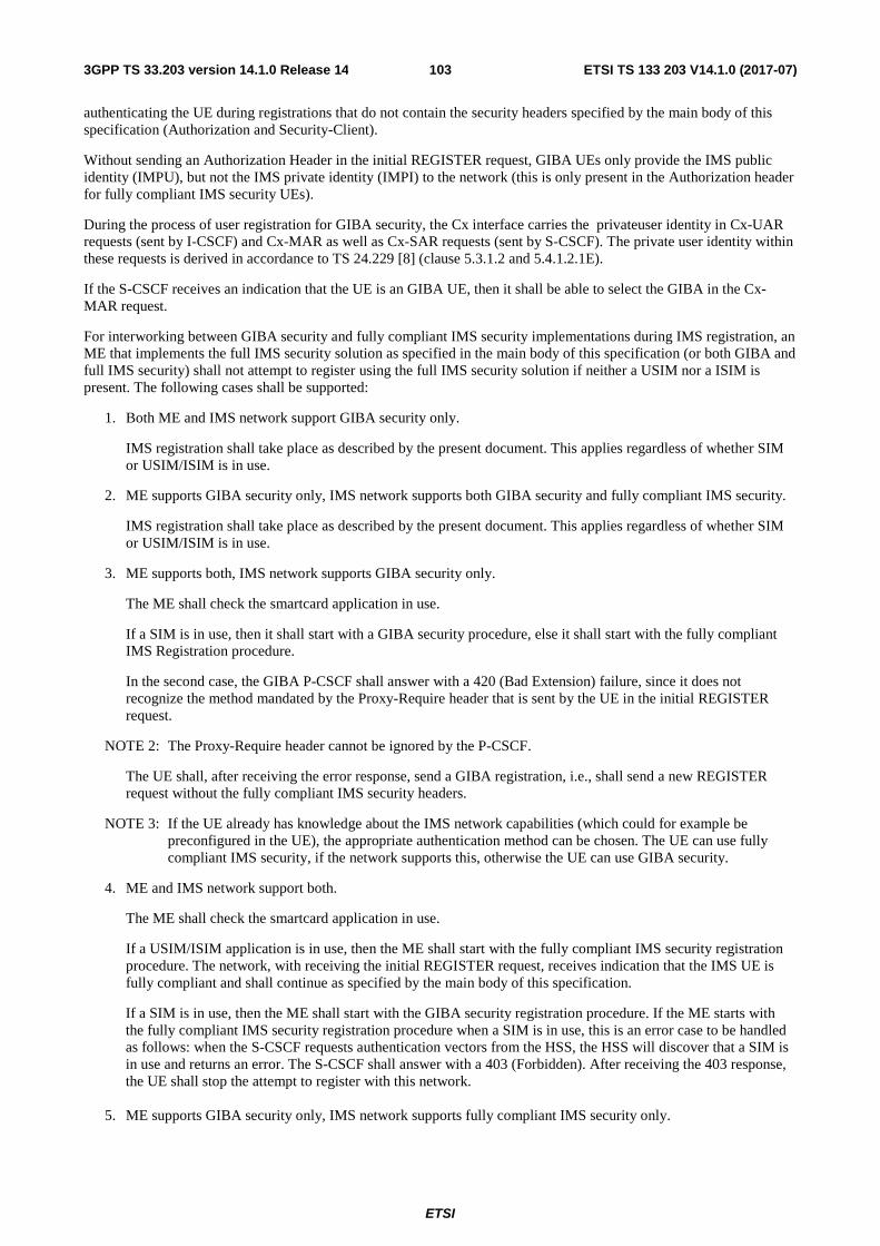
ETSI
ETSI TS 133 203 V14.1.0 (2017-07)1033GPP TS 33.203 version 14.1.0 Release 14
authenticating the UE during registrations that do not contain the security headers specified by the main body of this specification (Authorization and Security-Client).
Without sending an Authorization Header in the initial REGISTER request, GIBA UEs only provide the IMS public identity (IMPU), but not the IMS private identity (IMPI) to the network (this is only present in the Authorization header for fully compliant IMS security UEs).
During the process of user registration for GIBA security, the Cx interface carries the privateuser identity in Cx-UAR requests (sent by I-CSCF) and Cx-MAR as well as Cx-SAR requests (sent by S-CSCF). The private user identity within these requests is derived in accordance to TS 24.229 [8] (clause 5.3.1.2 and 5.4.1.2.1E).
If the S-CSCF receives an indication that the UE is an GIBA UE, then it shall be able to select the GIBA in the Cx-MAR request.
For interworking between GIBA security and fully compliant IMS security implementations during IMS registration, an ME that implements the full IMS security solution as specified in the main body of this specification (or both GIBA and full IMS security) shall not attempt to register using the full IMS security solution if neither a USIM nor a ISIM is present. The following cases shall be supported:
1. Both ME and IMS network support GIBA security only.
IMS registration shall take place as described by the present document. This applies regardless of whether SIM or USIM/ISIM is in use.
2. ME supports GIBA security only, IMS network supports both GIBA security and fully compliant IMS security.
IMS registration shall take place as described by the present document. This applies regardless of whether SIM or USIM/ISIM is in use.
3. ME supports both, IMS network supports GIBA security only.
The ME shall check the smartcard application in use.
If a SIM is in use, then it shall start with a GIBA security procedure, else it shall start with the fully compliant IMS Registration procedure.
In the second case, the GIBA P-CSCF shall answer with a 420 (Bad Extension) failure, since it does not recognize the method mandated by the Proxy-Require header that is sent by the UE in the initial REGISTER request.
NOTE 2: The Proxy-Require header cannot be ignored by the P-CSCF.
The UE shall, after receiving the error response, send a GIBA registration, i.e., shall send a new REGISTER request without the fully compliant IMS security headers.
NOTE 3: If the UE already has knowledge about the IMS network capabilities (which could for example be preconfigured in the UE), the appropriate authentication method can be chosen. The UE can use fully compliant IMS security, if the network supports this, otherwise the UE can use GIBA security.
4. ME and IMS network support both.
The ME shall check the smartcard application in use.
If a USIM/ISIM application is in use, then the ME shall start with the fully compliant IMS security registration procedure. The network, with receiving the initial REGISTER request, receives indication that the IMS UE is fully compliant and shall continue as specified by the main body of this specification.
If a SIM is in use, then the ME shall start with the GIBA security registration procedure. If the ME starts with the fully compliant IMS security registration procedure when a SIM is in use, this is an error case to be handled as follows: when the S-CSCF requests authentication vectors from the HSS, the HSS will discover that a SIM is in use and returns an error. The S-CSCF shall answer with a 403 (Forbidden). After receiving the 403 response, the UE shall stop the attempt to register with this network.
5. ME supports GIBA security only, IMS network supports fully compliant IMS security only.

ETSI
ETSI TS 133 203 V14.1.0 (2017-07)1043GPP TS 33.203 version 14.1.0 Release 14
The UE sends a REGISTER request to the IMS network that does not contain the security headers required by fully compliant IMS security. The fully compliant IMS security P-CSCF will detect that the Security-Client header is missing and return a 4xx response, as described in clause 5.2.2 of TS 24.229 [8]. This applies regardless of whether SIM or USIM/ISIM is in use.
6. ME supports fully compliant IMS security only, IMS network supports GIBA security only.
A ME supporting Full IMS security only is not aware of GIBA security, so its behaviour is expected to be compliant with the procedures defined in the main body of this specification. Based on this, if a SIM is in use, the ME should not attempt to register using the full IMS security solution. Whatever attempt would fail anyway, as Full IMS security requires ISIM/USIM.
If a USIM/ISIM application is in use, then the ME shall start with the fully compliant IMS security registration procedure. The GIBA P-CSCF shall answer with a 420 (Bad Extension) failure, since it does not recognize the method mandated by the Proxy-Require header that is sent by the UE in the initial REGISTER request. After receiving the error response, the UE shall stop the attempt to register with this network, since the fully compliant IMS security is not supported.
7. ME supports fully compliant IMS access security only, IMS network supports both.
A ME supporting Full IMS security only is not aware of GIBA security, so its behaviour is expected to be compliant with the procedures in the main body of this specification. Based on this, if a SIM is in use, the ME should not attempt to register using the full IMS security solution. Whatever attempt would fail anyway, as Full IMS security requires ISIM/USIM.
If a USIM/ISIM application is in use, then the ME shall start with the fully compliant IMS registration procedure. The network, with receiving the initial REGISTER request, receives indication that the IMS UE is fully compliant and shall continue as specified by the main body of this specification.
8. ME supports both, IMS network supports fully compliant IMS access security only.
The ME shall check the smartcard application in use.
If a USIM/ISIM application is in use, then the ME shall start with the fully compliant IMS registration procedure. The network, with receiving the initial REGISTER request, receives indication that the IMS UE is fully compliant and shall continue as specified by the main body of this specification.
If a SIM is in use, then the ME shall start with the GIBA security registration procedure (in this case the IMS authentication procedure will fail). In this context, if the ME starts with the fully compliant IMS security registration procedure, this is an error case: when the S-CSCF requests authentication vectors from the HSS, the HSS will discover that the SIM is in use and return an error. The S-CSCF shall answer with a 403 (Forbidden). After receiving the 403 response, the UE shall stop the attempt to register with this network.
9. Both ME and IMS network support fully compliant IMS access security only.
A ME supporting Full IMS security only is not aware of GIBA security, so its behaviour is expected to be compliant with the procedures specified in the main body of this specification. Based on this, if a SIM is in use, the UE should not attempt to register using the full IMS security solution. If the UE starts with the fully compliant IMS security registration procedure when a SIM is in use, this is an error case to be handled as follows: the HSS will discover that a SIM is in use and return an error to the S-CSCF. The S-CSCF shall answer with a 403 (Forbidden). After receiving the 403 response, the UE shall stop the attempt to register with this network.
If the USIM/ISIM application is in use, IMS registration shall take place as described by the main body of this specification.

ETSI
ETSI TS 133 203 V14.1.0 (2017-07)1053GPP TS 33.203 version 14.1.0 Release 14
T.8 Message Flows
T.8.1 Successful registration Figure T.1 below describes the message flow for successful registration to the IMS that is specified by the early IMS security solution.
NOTE: The "received" parameter is only sent from P-CSCF to S-CSCF under the conditions given in RFC 3261 [6].
The procedure is as follows.
The UE starts by setting up a PDP context.
When a PDP context has been set up successfully, the UE sends a SIP REGISTER. The REGISTER message contains the IP address and the IMPU of the UE.
The GGSN checks that the IP address provided in the REGISTER message matches the IP address allocated to the UE when the PDP context was set up. When the IP address has been verified, the GGSN forwards the REGISTER message to the P-CSCF.
The P-CSCF checks the source IP address against the IP address in the Via header of the REGISTER message. If the source IP address differs from the IP address in the Via header, the P-CSCF adds the source IP address to a received parameter in the Via header. The P-CSCF then forwards the REGISTER to the I-CSCF in the home network.
NOTE: The source IP address differs from the IP address in the Via header only in case the UE is malicious or the UE is misbehaving for some reason.
The I-CSCF contacts the HSS to authorize the UE. The HSS responds that the UE is authorized, and the I-CSCF forwards the SIP REGISTER message to the S-CSCF chosen to serve the UE.
The S-CSCF contacts the HSS and indicates that GIBA is used to authenticate the UE. The HSS returns the stored IP address to the S-CSCF. The S-CSCF then checks the IP address returned by the HSS against the IP address obtained in the REGISTER message ((if present, the received by parameter shall be used).
The S-CSCF sends a message to the HSS, informing that this S-CSCF is going to serve the UE, and the HSS responds which a message providing information that the S-CSCF needs for serving the UE.
The S-CSCF returns a SIP 200 OK to the UE, indicating that the registration is successfully completed.

ETSI
ETSI TS 133 203 V14.1.0 (2017-07)1063GPP TS 33.203 version 14.1.0 Release 14
Radius Server Radius Client
UE GGSN P-CSCF S-CSCF
Activate PDP Context
Request
HSS
Accounting Request Start Req.
(PDP Address Allocated –
ff.ee.dd.cc + MSISDN+IMSI)
Accounting Request Start Answer
SIP REGISTER (via: "sent-by" - ff.ee.dd.cc) (from: public user id of UE)
Check source IP address against SIP "via" field
Cx-MAR
(public user id of UE)
Cx-MAA
(IP Address stored ff.ee.dd.cc)
Check "received" IP address against IP address received
from HSS
SIP 200 OK
GGSN checks for IP address spoofing
SIP REGISTER (via: "sent-by" - ff.ee.dd.cc) (from: public user id of UE)
IP src: ff.ee.dd.cc
SGSN I-CSCF
Create PDP Context
Request
Create PDP Context
Response Activate PDP Context Accept
(PDP Address Allocated: ff.ee.dd.cc)
SIP REGISTER (via: "sent-by" - ff.ee.dd.cc) (from: public user id of UE)
IP src: ff.ee.dd.cc
Cx-UAR
(public user id of UE)
Cx-UAA
(public user id of UE)
SIP REGISTER (via: "sent-by" - ff.ee.dd.cc "received" – ff.ee.dd.cc)
(from: public user id of UE)
Cx-SAR
(public user id of UE)
Cx-SAA
Map public user id to MSISDN or IMSI to retrieve
associated IP address
Figure T.1: Message sequence for early IMS security showing a successful registration
T.8.2 Unsuccessful registration Figure T.2 below gives an example message flow for the unsuccessful attempt of an attacker trying to spoof the IMS identity of a valid IMS user.
NOTE: Again, the "received" parameter is only present between P-CSCF to S-CSCF under the conditions given in RFC 3261 [6].

ETSI
ETSI TS 133 203 V14.1.0 (2017-07)1073GPP TS 33.203 version 14.1.0 Release 14
The procedure is as follows.
UE1 sets up a PDP context. UE2 already has an active PDP context.
After UE1 has set up the PDP context, UE2 attempts to REGISTER using the IP address allocated to UE2, but using the IMPU of UE1.
The GGSN checks that the IP address provided in the REGISTER message matches the IP address allocated to the UE2 when the PDP context was set up. When the IP address has been verified, the GGSN forwards the REGISTER message to the P-CSCF.
The P-CSCF checks the source IP address against the IP address in the Via header of the REGISTER message. If the source IP address differs from the IP address in the Via header, the P-CSCF adds the source IP address to a received parameter in the Via header. The P-CSCF then forwards the REGISTER to the I-CSCF in the home network.
The S-CSCF contacts the HSS and indicates that GIBA is used to authenticate the UE. The HSS returns the stored IP address to the S-CSCF. The S-CSCF then checks the IP address returned by the HSS against the IP address obtained in the REGISTER message (if present, the received by parameter shall be used). Since the IP address stored by the HSS (the IP address of UE1) does not match the IP address in the REGISTER (IP address of UE2), the authentication fails. The S-CSCF returns a 403 Forbidden to the UE, indicating that the registration failed.
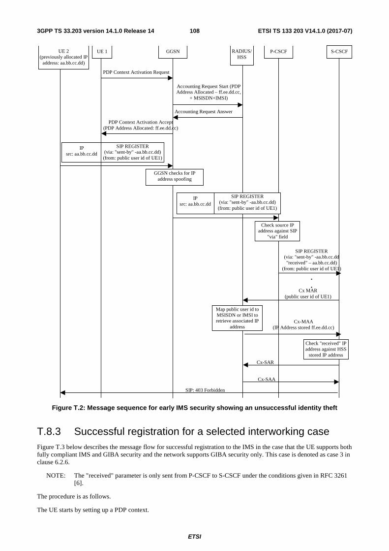
ETSI
ETSI TS 133 203 V14.1.0 (2017-07)1083GPP TS 33.203 version 14.1.0 Release 14
UE 1 GGSN P-CSCF S-CSCF
PDP Context Activation Request
PDP Context Activation Accept (PDP Address Allocated: ff.ee.dd.cc)
RADIUS/HSS
Accounting Request Start (PDP Address Allocated – ff.ee.dd.cc,
+ MSISDN+IMSI)
Accounting Request Answer
SIP REGISTER (via: "sent-by" -aa.bb.cc.dd) (from: public user id of UE1)
IP src: aa.bb.cc.dd
Check source IP address against SIP
"via" field
SIP REGISTER (via: "sent-by" -aa.bb.cc.dd "received" – aa.bb.cc.dd)
(from: public user id of UE1)
.
. Cx MAR
(public user id of UE1)
Cx-MAA (IP Address stored ff.ee.dd.cc)
Check "received" IP address against HSS
stored IP address
SIP: 403 Forbidden
UE 2 (previously allocated IP
address: aa.bb.cc.dd)
GGSN checks for IP address spoofing
SIP REGISTER (via: "sent-by" -aa.bb.cc.dd) (from: public user id of UE1)
IP src: aa.bb.cc.dd
Map public user id to MSISDN or IMSI to retrieve associated IP
address
Cx-SAR
Cx-SAA
Figure T.2: Message sequence for early IMS security showing an unsuccessful identity theft
T.8.3 Successful registration for a selected interworking case Figure T.3 below describes the message flow for successful registration to the IMS in the case that the UE supports both fully compliant IMS and GIBA security and the network supports GIBA security only. This case is denoted as case 3 in clause 6.2.6.
NOTE: The "received" parameter is only sent from P-CSCF to S-CSCF under the conditions given in RFC 3261 [6].
The procedure is as follows.
The UE starts by setting up a PDP context.

ETSI
ETSI TS 133 203 V14.1.0 (2017-07)1093GPP TS 33.203 version 14.1.0 Release 14
When a PDP context has been set up successfully, the UE sends a SIP REGISTER. As the UE supports fully compliant IMS security, the UE attempts to register using the procedures of fully compliant IMS security.
The P-CSCF does not support fully compliant IMS security, and returns an indication back to the UE that the network does not support fully compliant IMS security.
The UE sends a new REGISTER, this time according to the procedures of GIBA security. The REGISTER message contains the IP address and the IMPU of the UE.
The GGSN checks that the IP address provided in the REGISTER message matches the IP address allocated to the UE when the PDP context was set up. When the IP address has been verified, the GGSN forwards the REGISTER message to the P-CSCF.
The P-CSCF checks the source IP address against the IP address in the Via header of the REGISTER message. If the source IP address differs from the IP address in the Via header, the P-CSCF adds the source IP address to a received parameter in the Via header. The P-CSCF then forwards the REGISTER to the S-CSCF.
The S-CSCF contacts the HSS and indicates that GIBA is used to authenticate the UE. The HSS returns the stored IP address to the S-CSCF. The S-CSCF then checks the IP address returned by the HSS against the IP address obtained in the REGISTER message (if present, the received by parameter shall be used).
The S-CSCF sends a message to the HSS, informing that this S-CSCF is going to serve the UE, and the HSS responds which a message providing information that the S-CSCF needs for serving the UE.
The S-CSCF returns a SIP 200 OK to the UE, indicating that the registration is successfully completed.

ETSI
ETSI TS 133 203 V14.1.0 (2017-07)1103GPP TS 33.203 version 14.1.0 Release 14
UE 1 GGSN P-CSCF S-CSCF
PDP Context Activation Request
PDP Context Activation Accept (PDP Address Allocated: ff.ee.dd.cc)
RADIUS/HSS
Accounting Request Start (PDP Address Allocated – ff.ee.dd.cc,
+ MSISDN+IMSI)
Accounting Request Answer
SIP: 420 Bad Extension
GGSN checks for IP address spoofing
Check source IP address against SIP
"via" field
SIP REGISTER (via: "sent-by" - ff.ee.dd.cc
"received" – ff.ee.dd.cc)
Cx MAR (public user id of UE1)
Cx-MAA (IP Address stored ff.ee.dd.cc)
Check "received" IP address against HSS
stored IP address
SIP: 200 OK
GGSN checks for IP address spoofing
SIP REGISTER (via: "sent-by" - ff.ee.dd.cc)
IP src: ff.ee.dd.cc
Map public user id to MSISDN or IMSI to retrieve associated IP address
SIP REGISTER (Rel5 compliant)
IP src: ff.ee.dd.cc
SIP REGISTER (via: "sent-by" - ff.ee.dd.cc)
IP src: ff.ee.dd.cc
SIP REGISTER (Rel5 compliant)
IP src: ff.ee.dd.cc
Cx-SAR
Cx-SAA
Figure T.3: Message sequence for GIBA security showing interworking case where UE supports both fully compliant IMS security and GIBA security and network supports GIBA security only

ETSI
ETSI TS 133 203 V14.1.0 (2017-07)1113GPP TS 33.203 version 14.1.0 Release 14
Annex U (normative): Trusted Node Authentication (TNA)
U.1 Overview The main objectives and requirements on Trusted Node Authentication is that it shall be possible to gain access to IMS based on successful access level authentication being provided by a trusted node in the network which provides an interworking function towards the IMS. In practice this is achieved by having this trusted node take on the role of both the UE and the P-CSCF from an IMS perspective. One example of such a scenario is the MSC Server enhanced for ICS as described in TS 23.292 [50].
When registering to the IMS subsystem, the trust of the registering node is verified by the I-CSCF based on the visited network information (see TS 29.228 [39]) and network domain security (see TS 33.210 [5]). If the node is considered trusted, then the request is forwarded to the S-CSCF. The S-CSCF looks for an indication in the "integrity-protected" flag that authentication is already performed by the trusted node.
U.2 Use case and detailed description The main use case for TNA is to provide access to the IMS network for legacy or IMS enabled equipment when connected via a CS access domain as defined for ICS (see TS 23.292 [50]).
TNA relies on the following assumptions:
- The trusted node can be in either the home or visited network
- The trusted node provides sufficient means for authentication in the CS access domain
- The trusted node provides interworking between the IMS domain and the CS access domain
The authentication flow is depicted below in Figure U.1.

ETSI
ETSI TS 133 203 V14.1.0 (2017-07)1123GPP TS 33.203 version 14.1.0 Release 14
Figure U.1 Trusted Node performs registraton on behalf of the UE
The details of the signalling flows are as follows:
1. CS attach (UE A to Trusted Node)
As a result of some stimulus, UE A performs CS attachment toward the CS network
2. Authentication and Update Location (MSC/VLR to HLR/HSS)
The CS network performs standard CS location update, authentication and obtains subscriber data.
3. CS attach accept (MSC to UE A)
The CS attach request is accepted by the network, an accept message is sent to the UE.
4. REGISTER request (Trusted Node to I-CSCF)
The Trusted Node sends a SIP REGISTER to the I-CSCF with a private and temporary public user identity derived from the subscriber’s IMSI as well as an Instance ID. The REGISTER also contains information indicating the capabilities and characteristics of the Trusted Node as a SIP User Agent Client. The Trusted Node inserts an "integrity-protected" flag set to indicate that authentication has already been performed. The I-CSCF verifies that the incoming REGISTER originates from a trusted node (according to TS 33.210 [5]).
5. Cx: User registration status query procedure
The I-CSCF makes a request for information related to the Subscriber registration status by sending the private user identity, public user identity and visited domain name to the HSS as specified in see TS 29.228 [39]. The HSS returns the S-CSCF required capabilities and the I-CSCF uses this information to select a suitable S-CSCF.
6. REGISTER request (I-CSCF to S-CSCF)

ETSI
ETSI TS 133 203 V14.1.0 (2017-07)1133GPP TS 33.203 version 14.1.0 Release 14
I-CSCF forwards the REGISTER request to the selected S-CSCF.
7. Cx: S-CSCF Registration Notification
Based on the presence of the "integrity-protected" flag set to indicate that authentication has already been performed, the S-CSCF knows that the subscriber has already been authenticated by the Trusted Node. The S-CSCF informs the HSS that the user has been registered. Upon being requested by the S-CSCF, the HSS will also include the user profile in the response sent to the S-CSCF. For detailed message flows see TS 29.228 [39].
8. 200 (OK) response (S-CSCF to I-CSCF)
The S-CSCF sends a 200 (OK) response to the I-CSCF indicating that Registration was successful.
9. 200 (OK) response (I-CSCF to Trusted Node)
The I-CSCF forwards the 200 (OK) response to the MSC Server enhanced for ICS indicating that Registration was successful.

ETSI
ETSI TS 133 203 V14.1.0 (2017-07)1143GPP TS 33.203 version 14.1.0 Release 14
Annex V (informative): NAT deployment considerations for GIBA In the current IMS architecture, it is assumed that no NAT is present between the GGSN and the P-CSCF in GIBA (or that it is kept transparent to the UE). If a NAT device is between the GGSN and P-CSCF, problems may arise if it is not deployed properly. Although there is no IP address theft, when signaling messages traverse the NAT device, the source IP address may be translated. When P-CSCF compares the source IP address in the IP header with the one in the SIP header, it will find that these two IP address are not equal, and will attach the source IP address in the IP header to the “received” parameter of the Via header in the SIP header. When the request message is forwarded to the S-CSCF, the S-CSCF shall compare the IP address in the “received” parameter with the one stored in HSS. These two IP addresses may not be equal, and the registration will fail. This implies that GIBA will not be able to distinguish between address translation caused by NAT and IP address theft.
There are two deployment options that can be used to mitigate this problem.
A) If a NAT is deployed between GGSN and P-CSCF, it shall be controlled by the Operators and kept transparent to the UE. The P-CSCF can retrieve the address mapping information from the NAT device, and add the correct address information in the SIP message. The precise way of getting the address mapping information from the NAT is outside the scope of this specification.
NOTE 1: A common practice among NAT devices is to implement such address mapping information query interface based on a standardized protocol like SNMP.
B) A second alternative to solve the NAT problem is to ensure that the NAT function is provided in the P-CSCF (see also TS 23.228 [3]). The P-CSCF may have two interfaces. The internal interface has a private IP address and communicates with the private address space where the UE resides. The external interface has a public IP address and communicates with the public address space where the IMS core devices reside. This will then also ensure that the correct IP address is provided in the SIP message towards the S-CSCF.
NOTE 2: In practical deployment, a P-CSCF may have more than one internal interface to extend the capability to hold multiple private networks.
NOTE 3: The two solutions here only define the NAT traversal of the GPRS-IMS bundled authentication signaling. Media flow NAT traversal in above cases can be correspondingly solved using the mechanism defined in 3GPP TS 23.228 Annex G [3].

ETSI
ETSI TS 133 203 V14.1.0 (2017-07)1153GPP TS 33.203 version 14.1.0 Release 14
Annex W (normative): Tunnelling of IMS Services over Restrictive Access Networks
W.1 Overview This Annex specifies two mechanisms for tunnelling of IMS Services over Restrictive Access Networks.
The mechanisms specified in this Annex shall only be applicable when the IP traffic to the IMS core does not traverse through the Evolved Packet Core (EPC).
The mechanisms in this Annex are optional to implement.
W.2 Service and Media Reachability for Users over Restrictive Firewalls – Tunneled Firewall Traversal for IMS traffic
W.2.0 General This clause specifies firewall traversal mechanism that can be used for UE access to IMS services. Before using the mechanisms specified in this clause, the UE shall in accordance with normal procedures attempt to use existing NAT/FW traversal mechanisms as specified in TS 23.228 [3] and Annex M of this document. The exact procedure depends on the UE, the access, and operator policy.
This mechanism is called Enhanced Firewall Traversal Function (EFTF).
Editor’s Note: The functions required for this mechanism need to be detailed further, while re-using functions from the mechanism defined in Annex X.2 of 33.402 as much as possible when applicable. The Enhanced Firewall Traversal Function (EFTF) is not required to implement any ePDG functionality not required for IMS firewall traversal (e.g. authentication, ESP, APN handling, mobility protocols like PMIP). For IMS firewall traversal the S2b, Gxb and SWm reference points from 23.402 is not required.
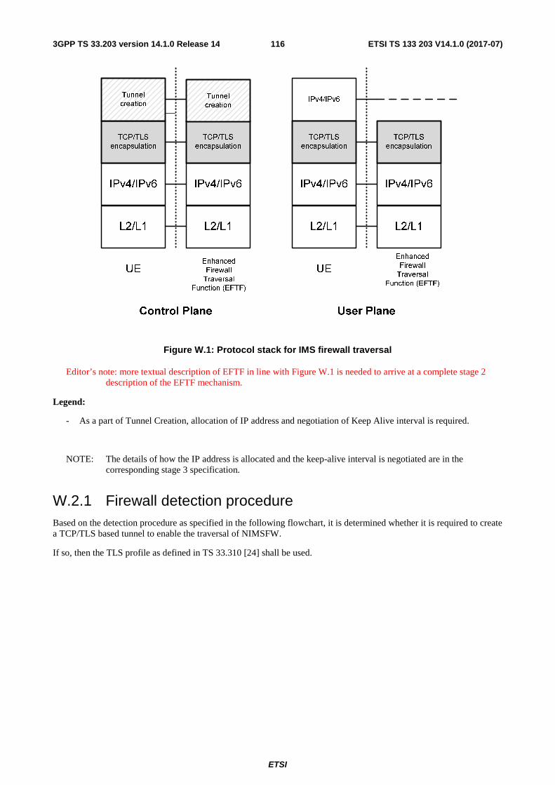
ETSI
ETSI TS 133 203 V14.1.0 (2017-07)1163GPP TS 33.203 version 14.1.0 Release 14
Figure W.1: Protocol stack for IMS firewall traversal
Editor’s note: more textual description of EFTF in line with Figure W.1 is needed to arrive at a complete stage 2 description of the EFTF mechanism.
Legend:
- As a part of Tunnel Creation, allocation of IP address and negotiation of Keep Alive interval is required.
NOTE: The details of how the IP address is allocated and the keep-alive interval is negotiated are in the corresponding stage 3 specification.
W.2.1 Firewall detection procedure Based on the detection procedure as specified in the following flowchart, it is determined whether it is required to create a TCP/TLS based tunnel to enable the traversal of NIMSFW.
If so, then the TLS profile as defined in TS 33.310 [24] shall be used.

ETSI
ETSI TS 133 203 V14.1.0 (2017-07)1173GPP TS 33.203 version 14.1.0 Release 14
Figure W.2: Flowchart for IMS firewall traversal
Once the TCP/TLS connection is established, the tunnel creation procedure involves negotiating IP address and keep-alive intervals.
W.3 Service and Media Reachability for Users over Restrictive Firewalls – Extensions to STUN/TURN/ICE
Editor’s note: Details on the extensions (HTTP CONNECT and detection mechanism for determining firewall types and explicit mention of supporting TCP port 443) to STUN/TURN/ICE is ffs.

ETSI
ETSI TS 133 203 V14.1.0 (2017-07)1183GPP TS 33.203 version 14.1.0 Release 14
W.3.1 Introduction
W.3.1.1 General
This clause specifies a firewall traversal solution for IMS control and media traffic based on SIP over TLS and an extended version of the ICE protocol [ICE, ICE-TCP]. In this solution, the TLS profile as defined in TS 33.310 [24] shall be used.
The method is intended for IMS clients that are located behind IMS-unaware firewalls and which fail to perform IMS registration and/or session establishment using the normal procedures. The method is likely to succeed as long as the firewall permits HTTP(S) traffic and does not perform extensive traffic monitoring. The method consists of two sub-solutions, one for the IMS media plane and one for the IMS control plane.
Note that this solution is only applicable to UEs which already support the use of ICE as defined in Annex G of TS 23.228 [3].
W.3.1.2 Firewall traversal for IMS control plane using SIP over TLS/TCP
Firewall traversal for IMS control plane is accomplished by running SIP over TLS and using port 443 (HTTPS) instead of the standard port 5061 (SIPS). This makes the SIP signalling appear as HTTPS traffic to any firewall that is present along the signalling path.
In order to ensure that the firewall pinholes are maintained, the IMS client -shall apply the keep-alive mechanism specified in RFC 5626 [32]. The keep-alive mechanism is negotiated by the IMS client and the P-CSCF at IMS registration using the method described in RFC 6223 [64]. Note that RFC 5626 defines two keep-alive techniques: a technique based on STUN for connection-less transports and a technique based on SIP (called CRLF) for connection-oriented transports. Since TCP is used as transport between the IMS client and the P-CSCF, the CRLF keep-alive technique must be used.
In case the IMS client is configured to use an HTTP proxy, the IMS client uses the HTTP CONNECT method (see RFC 2817 [62]) to request the proxy to establish a TCP connection with the P-CSCF on its behalf. Once the client has received a positive reply from the proxy that the TCP connection has been established, the client initates the TLS handshake with the P-CSCF and establishes the TLS tunnel. Note that the use of the HTTP CONNECT method is completely transparent to P-CSCF.
Editor’s note: It needs to be verified that this does not interfere with the HTTP proxy settings on the UE.
W.3.1.3 Firewall traversal for IMS media plane using ICE and TURN
Firewall traversal for IMS media plane is accomplished by using the ICE protocol together with an enhanced version of TURN. ICE is defined in RFC 5245[58] and is a protocol for performing NAT traversal of UDP based media streams. ICE in turn makes use of TURN, defined in RFC 5766 [60], which is a protocol for relaying media through a relay server. An IMS client that supports ICE will allocate relayed candidates at the TURN server and include the candidate information in the SDP offer/answer sent to the peer. The relayed candidates will be used as a last resort when the client and peer fail to establish a direct communication path. The communication between the client and the TURN server (this includes both the relayed media and the control information needed to setup the relayed candidates) can occur over UDP, TCP or TCP/TLS. By using TCP/TLS on port 443 (HTTPS) or TCP on port 80 (HTTP) the communication will appear as HTTP(S) to firewalls and will (typically) be allowed through. Using TCP instead of TLS/TCP reduces the overhead but will fail when the firewall performs DPI or if an HTTP proxy is present. An IMS client may be configured to use both TURN over TCP/80 and TURN over TLS/443, in such case, the client should prefer to use TURN over TCP/80 to avoid TLS overhead.
ICE and TURN have later on been extended to also support TCP based media. ICE TCP is defined in RFC 6544 [59] and TURN TCP is defined in RFC 6062 [61]. One of the changes introduced in TURN TCP is that the multiple TCP connections are established between the client and TURN server: one for exchange of control information and one for each relayed TCP based media stream. All UDP based media streams are relayed over the same TCP connection that is used for the control information, just as in the original TURN protocol. The TURN server will use TCP/TLS on port 443 (HTTPS) or TCP over port 80 (HTTP) for all the connections. In order to reduce the TLS setup time when several TCP connections are established, the IMS client and TURN server may use the TLS session resumption feature.

ETSI
ETSI TS 133 203 V14.1.0 (2017-07)1193GPP TS 33.203 version 14.1.0 Release 14
An IMS client that is configured to use an HTTP proxy uses the HTTP CONNECT method (see RFC 2817 [62]) to request the proxy to establish a TCP connection with the TURN server. Once the client has received a positive reply from the proxy that the TCP connection has been established, the client initates the TLS handshake with the TURN server and establishes the TLS tunnel. This procedure is repeated once for every TCP connection the client establishes with the TURN server. Note that the use of the HTTP CONNECT method is completely transparent to TURN server.
Using ICE for firewall traversal is particularly suitable for IMS clients that already implement ICE for NAT traversal, since in this case only minimal changes are required to the client. Usage of ICE for IMS clients is specified in TS 23.228 [3] and TS 24.229 [8].
Note that there is no need to specify any keep-alive mechanism since this functionality is already included in ICE. The IMS client will send regular STUN keep-alives which ensures that the firewall pinholes are maintained.
Editor's note: ICE TCP is required for TCP based media (e.g. MSRP) but is not yet supported in TS 23.228 [3] and TS 24.229 [8]. These specifications need to be updated.
Editor's note: How the client is authenticated and authorized by the TURN server is ffs. One possibility is to use the SIP Digest credentials and the normal TURN authentication procedure. However, this would require an additional interface between the TURN server and the HSS. Another possibility is to use GBA but this would perhaps be unnecessarily complex considering that the only attack we need to protect against is DoS.
W.3.2 Reference model Figure W.1 presents the reference model for IMS access when the IMS client uses the firewall traversal mechanism outlined in this section.
In case the remote endpoint does not support ICE, the P-CSCF may instruct the IMS-ALG to insert the IMS Access Gateway in the media path and terminate ICE. The procedure is described in TS 24.229 [8] and continues to function in the same way, i.e. the IMS-ALG and IMS-AGW are not impacted by the firewall traversal solution.
Note that the media may take several routes depending on which ICE candidates that succeed first. Media will only be relayed through the TURN server if all ICE candidates with higher priority fail.
Also note that the STUN server is included in Figure W.1 for sake of completeness. There is no impact on this function.
Figure W.1: Reference model for IMS access when firewall traversal is performed using SIP over TCP/TLS and ICE
W.3.3 Required functions of the UE For firewall traversal of IMS control plane, the IMS client shall implement the following functionality:

ETSI
ETSI TS 133 203 V14.1.0 (2017-07)1203GPP TS 33.203 version 14.1.0 Release 14
- support SIP over TLS/TCP on the non-standard port 443 (HTTPS);
- support the SIP Digest authentication method according to Annex N;
- support the CRLF keep-alive technique defined in RFC 5626 [32] together with the negotiation mechanism defined in RFC 6223 [64];
- support the HTTP CONNECT method in RFC 2817 [X5] for establishing the TLS tunnel with the P-CSCF when the IMS client is configured with an HTTP proxy.
For firewall traversal of IMS media plane, the IMS client shall implement the following functionality:
- support ICE for UDP and TCP based media streams according to Annex G of TS 23.228 [3];
- support TLS/TCP on non-standard port 443 and TCP on non-standard port 80 for communication with TURN server;
- support the HTTP CONNECT method in RFC 2817 [62] for establishing TLS tunnels with the TURN server when the IMS client is configured with an HTTP proxy.
Note that the HTTP CONNECT method is only used when the IMS client is configured with an HTTP proxy for outgoing HTTP(S) requests. The way in which the IMS client obtains the proxy address and port is out of scope.
W.3.4 Required functions of the P-CSCF For firewall traversal of IMS control plane, the P-CSCF shall implement the following functionality:
- support SIP over TLS/TCP on the non-standard port 443 (HTTPS);
- support the SIP Digest authentication method according to Annex N;
- support the CRLF keep-alive technique defined in RFC 5626 [32] together with the negotiation mechanism defined in RFC 6223 [64].
W.3.5 Required functions of the TURN server The TURN server shall, in addition to the requirements specified in Annex G of TS 23.228 [3], implement the following functionality:
- Support TLS/TCP on non-standard port 443 and (optionally) TCP on non-standard port 80 for communication with IMS client
W.3.6 Required functions of the IMS-ALG and IMS-AGW The requirements for the IMS-ALG and IMS-AGW specified in TS 24.228 [11] apply without changes.
NOTE: The IMS-ALG is invoked by the P-CSCF, IBCF, or ISC to handle the case when the remote endpoint lacks support of ICE. The IMS-ALG in turn inserts the IMS-AGW on the media path.
Editor’s note: IMS-AGW may be inserted in other cases as well, e.g. for hosted NAT.
ETSI
ETSI TS 133 203 V14.1.0 (2017-07)1213GPP TS 33.203 version 14.1.0 Release 14
Annex X (Normative): Security for WebRTC IMS Client access to IMS
X.1 Introduction This annex specifies the security required for the signalling procedures described in TS 23.228 [3] for WebRTC IMS Client access to IMS.
The provisions in the present annex are optional for implementation. The provisions in the present annex are optional for use.
For this release of the present specification, only the descriptions relating to the reference points in the IMS core, i.e. the interfaces between eP-CSCF, I-CSCF, S-CSCF, and HSS are normative. The descriptions of the reference points between WIC, WWSF, and eP-CSCF are of informative nature only. The latter are therefore to be considered as examples only, and implementations may be compliant with this specification and yet realise the reference points between WIC, WWSF, and eP-CSCF in a way different from the one described in the present annex.
The present annex is structured according to the three registration scenarios for WebRTC IMS Clients described in TS 23.228 [3].
This annex also describes solutions for TURN credential provisioning and authentication of WebRTC IMS clients when ICE/TURN is used as a mechanism to provide solution for traversing symmetric NAT and restrictive firewalls.
X.2 Authentication of WebRTC IMS Client with IMS subscription re-using existing IMS authentication mechanisms
X.2.0 General The present clause X.2 deals with the security aspects of the registration scenario described in TS 23.228 [3] that is entitled "WIC registration of individual Public User Identity using IMS authentication".
X.2.1 General requirements The following security requirements apply to all solutions for the present registration scenario:
- REQ 1.0: For the reference interface W1 (WIC to WWSF), one way authentication (WIC needs to authenticate WWSF) is needed. For the interface W2 (WIC to eP-CSCF), mutual authentication is required.
- REQ 1.1: The eP-CSCF shall verify that the WIC establishing the signalling connection with the eP-CSCF comes from a trusted domain.
When the WIC has access to the USIM/ISIM in the UE, IMS AKA scheme shall be used for authenticating WebRTC IMS Client, as defined in section X.2.3 of this document.
X.2.2 Solution 1.1: Use of SIP Digest credentials
X.2.2.1 General
In solution 1.1 it is assumed that the user has a subscription with an individual IMPU. The WebRTC IMS Client (WIC) is provided with the user's SIP Digest credentials and uses SIP Digest to register with IMS. The eP-CSCF is assumed to relay the authentication information so that the message flows are unchanged. The use of SIP Digest in IMS is specified in Annex N of this document.

ETSI
ETSI TS 133 203 V14.1.0 (2017-07)1223GPP TS 33.203 version 14.1.0 Release 14
NOTE: The use of SIP Digest breaks the security requirement mandating IMS AKA to connect to IMS when using a 3GPP access network. See Annex N of this document.
It is recommended to maintain a clear separation between WICs and regular IMS UEs. A user accessing IMS from a WIC should be assigned a separate subscription in the HSS with a unique IMPI and SIP Digest password. In this way a compromised password will have an isolated impact and only affect the WIC.
The entities that have access to the IMPI and SIP Digest password, and thus needs to be trusted by the operator, are the user, the browser, the WWSF, and the IMS core network. (The WWSF is included here since it has the ability to inject rogue JavaScript code into the WIC). SIP Digest should therefore only be used when the WWSF is controlled by the operator or a 3rd party trusted by the operator.
X.2.2.2 Requirements
No requirements have been identified.
X.2.2.3 Procedures
Figure X.2.3-1 shows the registration flow. In this figure SIP over secure WebSocket is used between the WIC and the eP-CSCF. Other protocols (e.g. HTTP RESTful or JSON over WebSocket) can also be used as long as it is able to relay the digest challenge, challenge-response, and auth-info values.
Solution 1.1 requires that the IMPU and SIP Digest password are made available to the JavaScript in the WIC. The IMPI can be omitted from the initial SIP Register request, and if that is the case the S-CSCF will try to determine its value from the registering IMPU. This requires that IMPUs are not shared between IMS users (see Annex N).
NOTE 1: It is assumed that the credentials are entered by the user via the web GUI or retrieved from the WWSF over HTTPS. Note that the latter option requires that WWSF has authenticated the user previously.
NOTE 2: Unless the SIP Digest password or the intermediate hash value H(A1) (see RFC 2617 [12]) is stored in the WIC, the password needs to be re-obtained each time a re-registration is performed. If the password is entered manually and if re-registrations occur often, this will result in a negative user experience. This can be avoided by storing the SIP Digest password or H(A1) in the WIC after the initial registration procedure. Ensuring the confidentiality of the SIP Digest password or H(A1) during storage is at the discretion of the implementation and is outside the scope of 3GPP.
NOTE 3: It is recommended that the user does not enter his SIP Digest credentials into the WIC, except possibly once before the initial registration.
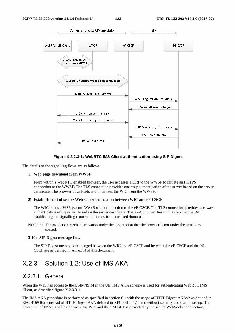
ETSI
ETSI TS 133 203 V14.1.0 (2017-07)1233GPP TS 33.203 version 14.1.0 Release 14
WebRTC IMS Client eP-CSCF I/S-CSCF
4. SIP Register (IMPI*,IMPU)
5. SIP 4xx digest-challenge
8. SIP Register digest-response
3. SIP Register (IMPI*,IMPU)
6. SIP 4xx digest-challenge
7. SIP Register digest-response
10. 2xx auth-info
SIP
WWSF
1. Web page down-
loaded over HTTPS
2. Establish secure WebSocket connection
9. SIP 2xx auth-info
Alternatives to SIP possible
Figure X.2.2.3-1: WebRTC IMS Client authentication using SIP Digest
The details of the signalling flows are as follows:
1) Web page download from WWSF
From within a WebRTC-enabled browser, the user accesses a URI to the WWSF to initiate an HTTPS connection to the WWSF. The TLS connection provides one-way authentication of the server based on the server certificate. The browser downloads and initializes the WIC from the WWSF.
2) Establishment of secure Web socket connection between WIC and eP-CSCF
The WIC opens a WSS (secure Web Socket) connection to the eP-CSCF. The TLS connection provides one-way authentication of the server based on the server certificate. The eP-CSCF verifies in this step that the WIC establishing the signalling connection comes from a trusted domain.
NOTE 3: The protection mechanism works under the assumption that the browser is not under the attacker's control.
3-10) SIP Digest message flow
The SIP Digest messages exchanged between the WIC and eP-CSCF and between the eP-CSCF and the I/S-CSCF are as defined in Annex N of this document.
X.2.3 Solution 1.2: Use of IMS AKA
X.2.3.1 General
When the WIC has access to the USIM/ISIM in the UE, IMS AKA scheme is used for authenticating WebRTC IMS Client, as described figure X.2.3.3-1.
The IMS AKA procedure is performed as specified in section 6.1 with the usage of HTTP Digest AKAv2 as defined in RFC 4169 [65] (instead of HTTP Digest AKA defined in RFC 3310 [17]) and without security association set-up. The protection of IMS signalling between the WIC and the eP-CSCF is provided by the secure WebSocket connection.

ETSI
ETSI TS 133 203 V14.1.0 (2017-07)1243GPP TS 33.203 version 14.1.0 Release 14
The ME shall be able to apply access control policy to the WIC before granting the access to the UICC application in charge of the IMS AKA authentication for WebRTC.
NOTE: Precision on how the ME could apply access control policy to restrict access to UICC is at the discretion of the ME implementation and is left out of scope of the present 3GPP release.
It is optional to have in the UICC an ISIM application that would be dedicated to WebRTC usage in order to maintain a clear separation between WebRTC Client and regular IMS UEs. This ISIM application dedicated to WebRTC could have separate subscription in the HSS (with unique IMPI and key K). In this way an attack will have an isolated impact and only affect the WebRTC IMS Client.
X.2.3.2 Requirements
No requirements have been identified.
X.2.3.3 Procedures
Figure X.2.3.3-1 shows the registration flow:
Figure X.2.3.3-1: WebRTC client authentication using IMS AKA
- Web page download from WWSF
From within a WebRTC-enabled browser, the user accesses a URI to the WWSF to initiate an HTTPS connection to the WWSF. The TLS connection provides one-way authentication of the server based on the server certificate. The browser downloads and initializes the WIC from the WWSF.
- Establishment of secure Web socket connection between WIC and eP-CSCF
The WIC opens a WSS (secure Web Socket) connection to the eP-CSCF. The TLS connection provides one-way authentication of the server based on the server certificate.The eP-CSCF verifies in this step that the WIC establishing the signalling connection comes from a trusted domain.
ETSI
ETSI TS 133 203 V14.1.0 (2017-07)1253GPP TS 33.203 version 14.1.0 Release 14
NOTE 1: The protection mechanism works under the assumption that the browser is not under the attacker's control.
- IMS AKA Procedure (from Step 1 to Step 8)
The IMS AKA procedure is performed as specified in section 6.1 with differences as explained below.
HTTP Digest AKAv2 is used as defined in RFC 4169 [65] (instead of HTTP Digest AKA defined in RFC 3310 [17]) and no IPsec security association is set-up. The keys CK and IK shall not be forwarded by the S-CSCF to thee P-CSCF in SM4. Hence, any statements relating to the use of these keys in the eP-CSCF do not apply.
The WebRTC IMS Client forwards necessary IMS AKA information to the UICC application in charge of the IMS AKA authentication for WebRTC.
The ME applies access control policy to the WIC before granting the access to the UICC application in charge of the IMS AKA authentication for WebRTC.
This UICC application sends back the results of the AUTHENTICATE command executed to perform the IMS AKA authentication, as defined in section 8 of this document. After successful execution of the AUTHENTICATE command, the ME securely derives the HTTP Digest password as described in RFC 4169 [65] using algorithm name equal to "AKAv2-SHA-256" and associated pseudo-random function (PRF) as defined in RFC 4169 [65] The algorithm value equals to SHA-256 in RFC 3310[17]. The WebRTC IMS Client uses this HTTP Digest password to provide the authentication response in the SIP Register message. The WIC shall not have access to the keys CK and IK.
NOTE: The messages SM2, SM8, SM9 and SM11 mentioned in the following are defined in clause 6 of this specification.
The eP-CSCF shall forward the REGISTER request to the S-CSCF including the "integrity-protected" header field parameter with the value set to "tls-connected" in message SM2 if the REGISTER request was received over the TLS connection between the WIC and the eP-CSCF. The eP-CSCF sends message SM8 with a TLS integrity protection indicator indicating the logical value "authentication pending". When the eP-CSCF receives message SM11 (200 OK), it shall associate the UE’s IP address and port of the TLS connection with the TLS session ID, the IMPI and all the successfully registered IMPUs related to that IMPI. From this point onwards for WebRTC session, the eP-CSCF shall not accept any SIP signalling messages outside the TLS connection other than messages relating to emergency services in accordance to TS 24.229 [8] and TS 23.167 [31].
In the REGISTER message received by the S-CSCF, if the value of the "integrity-protected" flag is set to "tls-connected" and "algorithm" parameter in the Authorization header has the value "AKAv2-SHA-256", the S-CSCF concludes that the REGISTER request relates to IMS AKA with HTTP Digest AKAv2 over TLS session set-up prior to registration.
The S-CSCF shall derive the HTTP Digest password as described in RFC 4169 [65] using algorithm name equal to "AKAv2-SHA-256" and associated pseudo-random function (PRF) After message SM9, if the authentication of the UE is successful, the S-CSCF shall associate the registration with the local state "tls-protected". An S-CSCF shall accept a REGISTER message with a TLS integrity protection indicator indicating "authentication pending" only if it contains a verifiable Digest value computed over a valid challenge according to RFC 4169 [65].
.
X.3 Authentication of WebRTC IMS Client with IMS subscription using web credentials
X.3.0 General The present clause X.3 deals with the security aspects of the registration scenario described in TS 23.228 [3] that is entitled "WIC registration of individual Public User Identity based on web authentication".

ETSI
ETSI TS 133 203 V14.1.0 (2017-07)1263GPP TS 33.203 version 14.1.0 Release 14
X.3.1 General requirements The following security requirements apply to the present registration scenario:
- REQ 2.0: For the interface W1 (WIC to WWSF) mutual authentication is required, unless the user's web identity is authenticated by the WAF, in which case only one-way authentication is required. For the interfaces W2 (WIC to eP-CSCF), and W4, if present, (WWSF to WAF), mutual authentication is required.
- REQ 2.1: An IMS service provider shall ensure that a third party authenticating a WebRTC IMS Client (WIC) and authorizing it to register with an IMS network using certain IMS identities has been granted the right to do so by the IMS subscriber owning these IMS identities. In case of a potential security breach affecting that third party, IMS subscribers that did not grant any right to that third party shall not be affected.
- REQ 2.2: An IMS service provider should be able to identify and mitigate security anomalies or security breaches at one third party entity authenticating or authorizing WebRTC IMS Clients , without affecting clients associated with other such third party entities.
- REQ 2.3: To prevent a third party from providing authorization information to a WebRTC IMS Client (WIC) without having been authorized by the IMS service provider to do so, an IMS service provider shall be able to identify the granting third party each time the IMS subscriber registers with the IMS network through the W2 interface. The identity of the third party shall be determined from the authorization information securely received by the IMS network over W2.
- REQ 2.4: An IMS service provider relying on a third party for authenticating or authorizing WebRTC IMS Clients (WIC), shall securely determine from the received authorization information the IMPI and IMPU of the authenticated WIC attempting to register with the IMS network.
NOTE: In a use-case where IMPI is associated with multiple IMPUs, IMPI to IMPU association check when I-CSCF User Registration Query is processed by the HSS, is not enough. For example, a user who has authenticated to the WWSF as sip:[email protected] but changes "To" field in the W2 REGISTER message to sip:[email protected], will not be detected by the IMS network. It is therefore necessary to determine IMPU and IMPI of the authenticated user from the received authorization information.
- REQ 2.5: It shall be ensured that a third party authenticating and authorizing a WebRTC IMS Clienthas enough information to guarantee that the user is entitled to use the IMS private identity IMPI determined from the user's web identity authenticated by the third party.
- REQ 2.6: The eP-CSCF shall verify that the WIC establishing the signalling connection with the eP-CSCF comes from a trusted domain.
X.3.2 Solution 2.1
X.3.2.1 General
In the present registration scenario it is assumed that the user has a subscription with an individual IMPU, but uses a web identity and authentication scheme to authenticate with the WWSF or the WAF. (Whether it is the WWSF or the WAF depends on the deployment.)
X.3.2.2 Requirements
All requirements for solution 2.1 are covered in clause X.3.1.

ETSI
ETSI TS 133 203 V14.1.0 (2017-07)1273GPP TS 33.203 version 14.1.0 Release 14
X.3.2.3 Procedures
The procedure provided in this clause is split into a normative part and non-normative part: the description for the interfaces between eP-CSCF, I-/S-CSCF and HSS is normative while the description for the interfaces W1, W2 and W4 is only by way of example.
NOTE 1: This split into a normative part and a non-normative part is due to 3GPP’s decision not to standardise the interfaces W1, W2 and W4 in the present release.
For the non-normative part, the procedure allows for various realisations that are out of scope of 3GPP for the present release. All realisations have in common that the WAF issues authorization tokens that are provided to the WIC via the WWSF. The WIC presents this authorization token to the eP-CSCF during the IMS registration. The validation of the authorization token by the eP-CSCF is specific to the particular realisation. The authorization token allows the eP-CSCF to retrieve the IMS subscriber identity, the WAF and WWSF identities, validity period, and possible other authorization parameters.
The procedure in the present clause covers two cases of locating the authorization entity (WAF):
- The WAF is located in the IMS provider domain;
- The WAF is located in a third party domain.
NOTE 2: WWSF and WAF realisations can be physically co-located or physically separate; in the latter case, WWSF and WAF can reside in the same or in different domains.
An example signalling flow for the present registration scenario is shown in Figure X.3.2.3-1. In this figure, by way of example SIP over secure WebSocket is used between the WebRTC IMS Client and the eP-CSCF. Other protocols (e.g. HTTP RESTful or JSON over WebSocket) can also be used.
All steps in the procedure below apply to both cases of WAF location unless stated otherwise. For the example of OAuth 2.0 the WAF needs to be located in the IMS provider domain.
For the normative part, the procedure applies Trusted Node Authentication (TNA) specified for IMS in Annex U of the present specification. The trusted node is the eP-CSCF residing in the operator network, according to TS 23.228 [3]. The signalling between the Trusted Node and the rest of the IMS core is unchanged from the signalling flow in Annex U of the present specification with the following exception: if the WAF is located in a third party domain then the REGISTER message is enhanced with additional parameters (WAF and WWSF identity, if available), which are included to satisfy the requirements REQ 2.1 and REQ 2.2 from clause X.3.1 of the present specification.

ETSI
ETSI TS 133 203 V14.1.0 (2017-07)1283GPP TS 33.203 version 14.1.0 Release 14
Figure X.3.2.3-1: WebRTC IMS Client access to IMS using Trusted Node Authentication (example flow)
The details of the signalling flows are as follows:
Each step x in the signalling flow has a part x.1 providing general text applying to all realisations, irrespective of whether the WAF is located in the IMS provider domain or in a third party domain. This part x.1 is followed by text explaining how it would work for a realisation using the example of OAuth. For the example of OAuth, the WAF needs to be located in the IMS provider domain.
In addition, some of the steps contain a second step x.2 that applies only when the WAF is located in a third party domain.
0. WWSF obtains authorization token
0.1 General:
The WWSF requests an authorization token from the WAF. The WAF or WWSF, depending on the authorization flow used, authenticates the user via “web credentials”, i.e. credentials as commonly used for access to web based services, for example a username and password. The user's web identity is mapped to the corresponding IMS subscriber identity (i.e. IMPI and IMPU(s) ).
NOTE 3: It is assumed that the WWSF or WAF maintains the mapping between a user's web identity and IMPI/IMPU. How this mapping is established (i.e. how REQ 2.5 is satisfied) is out-of-scope of this specification.
Example of OAuth 2.0:

ETSI
ETSI TS 133 203 V14.1.0 (2017-07)1293GPP TS 33.203 version 14.1.0 Release 14
When using the example of OAuth 2.0 then one of the authorization flows defined by OAuth 2.0 is used.
- Authorization Code flow: The WAF authenticates both the user and the WWSF before it issues the access token. The WAF may also request the user to explicitly authorize the WWSF.
- Client Credentials flow: The WAF authenticates only the WWSF and the authorization is performed without user involvement. As part of the authorization, the WAF verifies that the WWSF has the necessary permissions to access the IMS account indicated in the request. It is assumed that the WWSF has authenticated the user prior to sending the token request.
In the example of OAuth 2.0 the authorization token is an access token and IMPI and IMPU are associated with the access token.
Using the terminology of OAuth 2.0, the IMS subscriber corresponds to the resource owner, the WWSF corresponds to the client, the WAF corresponds to the authorization server, and the IMS network corresponds to the resource server.
NOTE 4: Void.
1. Web page download from WWSF
1.1 General:
An example realisation of this step is as follows:
- From within a WebRTC-enabled browser, the user accesses a URI to the WWSF to initiate an HTTPS connection to the WWSF. The TLS connection provides one-way authentication of the server based on the server certificate. The browser downloads and initializes the WIC from the WWSF. The WWSF forwards the authorization token to the WIC for inclusion in IMS registration procedure (step 3 below).
Example of OAuth 2.0: Identical to 1.1.
2. Establishment of secure connection between WIC and eP-CSCF
2.1 General:
An example realisation of this step is as follows:
The WIC opens a WSS (secure Web Socket) connection to the eP-CSCF. The TLS connection provides one-way authentication of the server based on the server certificate. The eP-CSCF verifies in this step that the WIC establishing the signalling connection comes from a trusted domain.
NOTE 5: The protection mechanism works under the assumption that the browser is not under the attacker's control.
Example of OAuth 2.0: Identical to 2.1.
3. REGISTER request (WebRTC IMS Client to Trusted Node)
3.1 General:
An example realisation of this step is as follows:
The WebRTC IMS Client sends a REGISTER request. The REGISTER request includes an authorization token, which the WebRTC IMS Client has previously obtained.
Example of OAuth 2.0:
In addition to 3.1, the Authorization header in the REGISTER request includes the OAuth 2.0 access token obtained in step 1. The access token is of the so called "bearer" token type; see RFC 6750 [67].
NOTE 6: OAuth bearer tokens can be used with signalling protocols that supports the Authorization header defined in RFC 2617 [13], for example SIP and HTTP.
4. Validation of security token at eP-CSCF
4.1 General:

ETSI
ETSI TS 133 203 V14.1.0 (2017-07)1303GPP TS 33.203 version 14.1.0 Release 14
An example realisation of this step is as follows:
The eP-CSCF extracts the authorization token and validates it in some unspecified manner ensuring that only an authorized source can have generated the authorization token. The authorization token is associated with a specific resource owner (i.e. the IMS subscriber) and client (i.e. the WWSF) and has a certain lifetime and scope. This authorization information can either be encoded into the token itself and verified through a signature or MAC (so called self-contained token), or retrieved as part of the validation response if the validation is performed against the WAF.
If the authorization token is valid the eP-CSCF obtains the associated authorization information, including the IMPI and IMPU of the associated user, the WAF and WWSF identities(if available),, and the authorization token scope. The eP-CSCF verifies that the scope includes the value "webrtc-ims-client-access-to-ims"
NOTE 6a: In the present 3GPP release the token format and verification procedure is left out of scope. It is assumed that the eP-CSCF can check the validity of the token and obtain the subscriber IMPI and IMPU(s), the WWSF identity, lifetime, and scope parameters.
If the token is not valid in some respect, the eP-CSCF declines the register request, closes the web socket and aborts the procedure.
NOTE 7: The value "webrtc-ims-client-access-to-ims" is just a placeholder. The final syntax will be defined in the stage 3 specification.
Example of OAuth 2.0: Identical to 4.1.
From the beginning of step 5 until the end of step 7, the text in the present subclause X.3.2.3 is normative.
5. REGISTER request (eP-CSCF to S-CSCF)
5.1 General:
The eP-CSCF proceeds if the previous step has provided it with IMPI, IMPU(s) of the user requesting registration, an assurance that the user is authorised to use this IMPI and IMPU, and an identity of the WWSF and WAF. Then, the eP-CSCF generates a TNA Authorization header and forwards the request to the S-CSCF (via the I-CSCF). The format of the TNA Authorization header is specified in TS 24.292, Clause 6.2 [15], and contains, among others, the user’s IMPI, an integrity-protected directive set to auth-done, and an empty response directive.
Example of OAuth 2.0: Identical to 5.1.
5.2 Case of WAF located in third party domain:
In this case, in addition to step 5.1 the eP-CSCF includes the identity of the WAF and WWSF (if available).
6. Cx: S-CSCF Registration Notification
6.1 General:
Based on the presence of the "integrity-protected" directive set to indicate that authentication has already been performed, the S-CSCF knows that user’s authorization has already been validated by the Trusted Node. The S-CSCF informs the HSS that the user has been registered. Upon being requested by the S-CSCF, the HSS will also include the user profile in the response sent to the S-CSCF. For detailed message flows see TS 29.228 [16].
Example of OAuth 2.0: Identical to 6.1.
6.2 Case of WAF located in third party domain:
In this case, in addition to step 6.1, the HSS further includes a list of WAF and WWSF identities (if available), outside the IMS provider’s domain allowed for this IMS subscription. If the S-CSCF received an identity of the authorization entity from the eP-CSCF then the S-CSCF checks whether this identity is contained in the list received from the HSS. The S-CSCF further checks whether the identity of the authorization entity received from the eP-CSCF, if any, is not barred. If the performed checks are positive, or no checks need to be performed, the S-CSCF proceeds with the next step; otherwise, it rejects the registration.
NOTE 8: The S-CSCF can obtain information about barred authorization entities from the HSS or via OAM. Barring may be useful in isolating the effects of security breaches in third party domains.
ETSI
ETSI TS 133 203 V14.1.0 (2017-07)1313GPP TS 33.203 version 14.1.0 Release 14
7. 200 (OK) response (S-CSCF to eP-CSCF)
7.1 General:
The S-CSCF sends a 200 (OK) response to the eP-CSCF (via I-CSCF) indicating that Registration was successful.
When TLS is used between WIC and eP-CSCF, then, similar to the registration procedure for SIP Digest with TLS, the eP-CSCF associates the IMPI and all successfully registered IMPUs with the TLS Session ID when the 200 (OK) is received.
Example of OAuth 2.0: Identical to 7.1.
8. 200 (OK) response (eP-CSCF to WebRTC IMS Client)
8.1 General:
An example realisation of this step is as follows:
The eP-CSCF forwards the 200 (OK) response to the WebRTC IMS Client indicating that Registration was successful.
Example of OAuth 2.0: Identical to 8.1.
X.4 Assignment of IMS identities to WebRTC IMS Client from pool of IMS subscriptions held by WWSF
X.4.0 General The present clause X.4 deals with the security aspects of the registration scenario described in TS 23.228 [3] that is entitled "WIC registration of individual Public User Identity from a pool of Public User Identities".
X.4.1 General requirements The following security requirements apply to the present registration scenario:
- REQ 3.0: For the interfaces W2 (WIC to eP-CSCF), and W4, if present, (WWSF to WAF), mutual authentication is required. For the W1interface, mutual authentication is required, except for the case of anonymous user. In the case of anonymous user, one way authentication (WIC needs to authenticate WWSF) is required.
- REQ 3.1: The WAF shall provide authorization information to the eP-CSCF (possibly via the WIC) that allows the IMS core to ascertain that the WIC in possession of this authorization information is authorized to access IMS using the associated public and private IMS identities presented during registration or retrieved from the WAF through undefined means.
- REQ 3.2: An IMS service provider shall ensure that the private IMS identity provided in the authorization information from REQ 3.2 belongs to an IMS subscription in the pool of IMS subscriptions uniquely assigned to the WWSF.
- REQ 3.3: The eP-CSCF shall verify that the WIC establishing the signalling connection with the eP-CSCF comes from a trusted domain.

ETSI
ETSI TS 133 203 V14.1.0 (2017-07)1323GPP TS 33.203 version 14.1.0 Release 14
X.4.2 Solution 3.1
X.4.2.1 General
In the present registration scenario it is assumed that the ”WWSF is provided with a pool of subscriptions, each containing a single unique IMPU/IMPI pair, to IMS and can assign individual Public and Private User Identities from this pool.” (quoted from TS 23.228). This assignment is temporary and the same IMPU (and IMPI) may be re-assigned to a different user at a later time once they are free and available for re-use.
In an extension to this registration scenario, the IMS operator may also provide the WWSF with an unbounded number of IMPUs associated with IMPIs to be allocated to WIC users.
The user’s web identity may be authenticated by the WWSF or the WAF. (Whether it is the WWSF or the WAF depends on the deployment.), but the WWSF may decide not to authenticate the user. Unauthenticated users are anonymous to the WWSF and WAF, but may still be authorized for IMS service.
NOTE 1: The difference to the registration scenario addressed in clause X.3 is that, in the present registration scenario, the IMS subscriber is the WWSF, not the user. There is no linkage between the user’s web identity that may be authenticated by the WWSF or the WAF and the assigned IMS identities.
NOTE 2: Considerations on Lawful Interception, e.g. when the user is anonymous to the third party, are outside the scope of the present document.
X.4.2.2 Requirements
All requirements for solution 3.1 are covered in clause X.4.1.
X.4.2.3 Procedures
The procedure provided in this clause is split into a normative part and non-normative part: the description for the interfaces between eP-CSCF, I-/S-CSCF and HSS is normative while the description for the interfaces W1, W2 and W4 is only by way of example.
NOTE 3: This split into a normative part and a non-normative part is due to 3GPP’s decision not to standardise the interfaces W1, W2 and W4 in the present release.
For the non-normative part, the procedure allows for various realisations that are out of scope of 3GPP for the present release. All realisations have in common that the WAF issues authorization tokens that are provided to the WIC via the WWSF. The WIC presents this authorization token to the eP-CSCF during the IMS registration. The validation of the authorization token by the eP-CSCF is specific to the particular realisation. The authorization token allows the eP-CSCF to retrieve the IMS subscriber identity, the WAF and WWSF identities, validity period, and possible other authorization parameters.
The procedure in the present clause covers two cases of locating the authorization entity (WAF):
- The WAF is located in the IMS provider domain;
- The WAF is located in a third party domain.
NOTE 4: WWSF and WAF realisations can be physically co-located or physically separate; in the latter case, WWSF and WAF can reside in the same or in different domains.
An example signalling flow for the present registration scenario is shown in Figure X.3.3-1. In this figure, by way of example SIP over secure WebSocket is used between the WebRTC IMS Client and the eP-CSCF. Other protocols (e.g. HTTP RESTful or JSON over WebSocket) can also be used.
All steps in the procedure below apply to both cases of WAF location unless stated otherwise. For the example of OAuth 2.0 the WAF needs to be located in the IMS provider domain.
For the normative part, the procedure applies Trusted Node Authentication (TNA) specified for IMS in Annex U of the present specification. The trusted node is the eP-CSCF residing in the operator network, according to the present specification .

ETSI
ETSI TS 133 203 V14.1.0 (2017-07)1333GPP TS 33.203 version 14.1.0 Release 14
The signalling between the trusted node and the rest of the IMS core is unchanged from the signalling flow in Annex U of the present specification with the following exception: if the WAF is located in a third party domain then the REGISTER message may be enhanced with additional parameters (WAF and WWSF identity, if available), whose inclusion is conditional, to satisfy the requirements REQ 3.2 from clause X.4.1 of the present specification.
Figure X.4.2.3-1: WebRTC IMS Client access to IMS using Trusted Node Authentication (example flow)
The details of the signalling flows are as follows:
Each step x in the signalling flow has a part x.1 providing general text applying to all realisations, irrespective of whether the WAF is located in the IMS provider domain or in a third party domain. This part x.1 is followed by text explaining how it would work for a realisation using the example of OAuth. For the example of OAuth, the WAF needs to be located in the IMS provider domain.
In addition, some of the steps contain a second step x.2 that applies only when the WAF is located in a third party domain.
0. WWSF obtains authorization token
0.1 General:
The WWSF requests an authorization token from the WAF. The WWSF or the WAF authenticates the user via “web credentials”, i.e. credentials as commonly used for access to web based services, for example a username and password. The WWSF can choose not to authenticate the user if the user is to remain anonymous.

ETSI
ETSI TS 133 203 V14.1.0 (2017-07)1343GPP TS 33.203 version 14.1.0 Release 14
Example of OAuth 2.0:
When using the example of OAuth 2.0 then the following authorization flows defined by OAuth 2.0 is used.
- Client Credentials flow: The WAF authenticates only the WWSF and the authorization is performed without user involvement. As part of the authorization, the WAF verifies that the WWSF has the necessary permissions to access the IMS account indicated in the request. It is assumed that the WWSF has authenticated the user prior to sending the token request unless it is a case of anonymous access granted by the WWSF.
In the example of OAuth 2.0 the authorization token is an access token and IMPI and IMPU are associated with the access token.
Using the terminology of OAuth 2.0, the IMS subscriber corresponds to the resource owner, the WWSF corresponds to the client, the WAF corresponds to the authorization server, and the IMS network corresponds to the resource server. Note that, in this scenario, the WWSF is the IMS subscriber, so resource owner and client co-incide. Note further that the WWSF and the WAF may also co-incide.
NOTE 5: Void.
1. Web page download from WWSF
1.1 General:
An example realisation of this step is as follows:
- From within a WebRTC-enabled browser, the user accesses a URI to the WWSF to initiate an HTTPS connection to the WWSF. The TLS connection provides one-way authentication of the server based on the server certificate. The browser downloads and initializes the WIC from the WWSF. The WWSF forwards the authorization token to the WIC for inclusion in IMS registration procedure (step 3 below).
Example of OAuth 2.0: Identical to 1.1.
2. Establishment of secure Web socket connection between WIC and eP-CSCF
2.1 General:
An example realisation of this step is as follows:
The WIC opens a WSS (secure Web Socket) connection to the eP-CSCF. The TLS connection provides one-way authentication of the server based on the server certificate. The eP-CSCF verifies in this step that the WIC establishing the signalling connection comes from a trusted domain.
NOTE 6: The protection mechanism works under the assumption that the browser is not under the attacker's control.
Example of OAuth 2.0: Identical to 2.1.
3. REGISTER request (WebRTC IMS Client to Trusted Node)
3.1 General:
An example realisation of this step is as follows:
The WebRTC IMS Client sends a REGISTER request. The REGISTER request includes an authorization token, which the WebRTC IMS Client has previously obtained.
Example of OAuth 2.0:
In addition to 3.1, the Authorization header in the REGISTER request includes the OAuth 2.0 access token obtained in step 1. The access token is of the so called "bearer" token type; see RFC 6750 [67].

ETSI
ETSI TS 133 203 V14.1.0 (2017-07)1353GPP TS 33.203 version 14.1.0 Release 14
NOTE 7: OAuth bearer tokens can be used with signalling protocols that supports the Authorization header defined in RFC 2617 [13], for example SIP and HTTP.
4. Validation of security token at eP-CSCF
4.1 General:
An example realisation of this step is as follows:
The eP-CSCF extracts the authorization token and validates it in some unspecified manner ensuring that only an authorized source can have generated the authorization token. The authorization token is associated with a specific resource owner (i.e. the IMS subscriber) and client (i.e. the WWSF) and has a certain lifetime and scope. This authorization information can either be encoded into the token itself and verified through a signature or MAC (so called self-contained token), or retrieved as part of the validation response if the validation is performed against the WAF.
If the authorization token is valid the eP-CSCF obtains the associated authorization information, including the IMPI and IMPU assigned to the user by the WWSF, the WAF and WWSF identity (if available), and the authorization token scope. The eP-CSCF verifies that the scope includes the value "webrtc-ims-client-access-to-ims".
NOTE 7a: In the present 3GPP release the token format and verification procedure is left out of scope. It is assumed that the eP-CSCF can check the validity of the token and obtain the subscriber IMPI and IMPU(s), the WWSF identity, lifetime, and scope parameters.
NOTE 8: Under certain assumptions, the eP-CSCF can also verify that the IMPI, if it exists at all in the IMS, belongs to an IMS subscription in the pool of IMS subscriptions assigned to the WWSF.Such an assumption would be e.g. that the IMPIs from the pool of IMS subscriptions assigned to the WWSF have a special form, and the IMS provider does not assign IMPIs of this form to any other WWSF. However, the IMPU would not have to follow the same special format as the IMPI.
If the validation fails in some respect, the eP-CSCF declines the register request, closes the web socket and aborts the procedure.
NOTE 9: The value "webrtc-ims-client-access-to-ims" is just a placeholder. The final syntax will be defined in the stage 3 specification.
Example of OAuth 2.0: Identical to 4.1.
From the beginning of step 5 until the end of step 7, the text in the present subclause X.4.2.3 is normative.
5. REGISTER request (eP-CSCF to S-CSCF)
5.1 General:
The eP-CSCF proceeds if the previous step has provided it with IMPI, IMPU(s) of the user requesting registration, an assurance that the user is authorised to use this IMPI and IMPU, and an identity of the WWSF and WAF. Then, the eP-CSCF generates a TNA Authorization header and forwards the request to the S-CSCF (via the I-CSCF). The format of the TNA Authorization header is specified in TS 24.292, Clause 6.2 [15], and contains, among others, the IMPI assigned to the user, an integrity-protected directive set to auth-done, and an empty response directive.
Example of OAuth 2.0: Identical to 5.1.
5.2 Case of WAF located in third party domain:
In this case, in addition to step 5.1, if the eP-CSCF cannot not verify in step 4 that the IMPI, if it exists at all, belongs to an IMS subscription in the pool of IMS subscriptions assigned to the WWSF then the eP-CSCF includes the identity of the WAF and WWSF (if available).
6. Cx: S-CSCF Registration Notification
6.1 General:
Based on the presence of the "integrity-protected" directive set to indicate that authentication has already been performed, the S-CSCF knows that the user’s authorization has already been validated by the Trusted Node. The S-

ETSI
ETSI TS 133 203 V14.1.0 (2017-07)1363GPP TS 33.203 version 14.1.0 Release 14
CSCF informs the HSS that the user has been registered. Upon being requested by the S-CSCF, the HSS will also include the user profile in the response sent to the S-CSCF. For detailed message flows see TS 29.228 [16].
Example of OAuth 2.0: Identical to 6.1.
6.2 Case of WAF located in third party domain:
In this case, in addition to step 6.1, the HSS further includes a list, if available, of WWSF identities allowed for assigning this IMS subscription. If the S-CSCF received a WWSF identity from the eP-CSCF, the S-CSCF checks whether it is contained in this list. The S-CSCF further checks whether the identities of the WWSF and WAF,received from the eP-CSCF, if any,are not barred. If the performed checks are positive, or no checks need to be performed, the S-CSCF proceeds with the next step; otherwise, it rejects the registration.
NOTE 10: The S-CSCF can obtain information about barred authorization entities from the HSS or via OAM. Barring may be useful in isolating the effects of security breaches in third party domains.
7. 200 (OK) response (S-CSCF to eP-CSCF)
7.1 General:
The S-CSCF sends a 200 (OK) response to the eP-CSCF (via I-CSCF) indicating that registration was successful.
When TLS is used between WIC and eP-CSCF, then, similar to the registration procedure for SIP Digest with TLS, the eP-CSCF associates the IMPI and all successfully registered IMPUs with the TLS Session ID when the 200 (OK) is received.
Example of OAuth 2.0: Identical to 7.1.
8. 200 (OK) response (eP-CSCF to WebRTC IMS Client)
8.1 General:
An example realisation of this step is as follows:
The eP-CSCF forwards the 200 (OK) response to the WebRTC IMS Client indicating that Registration was successful.
Example of OAuth 2.0: Identical to 8.1.
X.5 TURN credential provisioning and authentication (informative)
X.5.1 Introduction TURN RFC 5766 [61] specifies that TURN servers and clients MUST implement "Long-Term Credential Mechanism" as specified in clause 10.2 of RFC 5389 [69]. In this mechanism, the client and server share a pre-provisioned username and password that remains in the system till the user is using the system.The TURN server uses these credentials to authenticate the client by performing digest challenge/response.
In IMS_WebRTC, the browser plays the role of a TURN client. The WIC (i.e. the Javascript code) controls the execution of the browser via the W3C defined RTCPeerConnection API. Through this API, the WIC provides TURN credentials to the browser. These credentials should therefore be made available to the WIC.
There are two known gaps that need to be addressed before TURN can be used in IMS_WebRTC:
1) At present, the provisioning of TURN long-term credentials in the WIC is un-defined.
2) Moreover, as indicated in RFC 7376 [68], ensuring secrecy of these credentials in a web-based application such as the WIC is difficult. Once these credentials are exposed to a Javascript script, it could lead to various security issues such as leak of the credentials, privacy leakage etc.

ETSI
ETSI TS 133 203 V14.1.0 (2017-07)1373GPP TS 33.203 version 14.1.0 Release 14
A solution is needed to dynamically configure the TURN credentials in the WIC while ensuring that security gaps identified by RFC 7376 [68] are addressed.
Two solutions are presented in this annex for TURN credential provisioning and authentication:a) eP-CSCF based dynamic provisioning of credentials in the WIC and TURN server
b) TURN client authentication based OAuth 2.0 access tokens.
Both solutions are optional for implementation.
X.5.2 Solution 1: TURN credential provisioning and authentication using eP-CSCF
X.5.2.1 Overview
This solution reuses the TURN long-term credential method defined in RFC 5766 [61] , but the credential is dynamically provisioned by eP-CSCF via the signalling channel. When WIC registers to IMS, WIC requests the IMS networks to provision a credential for TURN authentication using a 3GPP extension header. If the request is authenticated and authorized, eP-CSCF generates a TURN credential, including user id, password, expiration, etc, and sends the credential to WIC in the response message. Since the signaling messages between WIC and eP-CSCF are protected by the secure protocols, e.g. secure Websocket, the TURN credential is securely transferred to WIC. The WIC retrieves the credential and uses it in subsequent TURN allocation requests. The WIC may request TURN credential for every registration, or use the credential until it expires. WIC can also use other signaling messages such as OPTION to request a new credential at anytime before re-registration.
This method requires some enhancement of WIC and eP-CSCF. WIC needs to be enhanced to use the 3GPP extension header to request TURN credential from eP-CSCF via signaling messages. The eP-CSCF needs to be enhanced to process TURN credential request and generate TURN user name and password using a preshared key with the TURN server. The TURN server also needs to be enhanced to re-generate TURN password from username in TURN request and the preshared key with P-CSCF.
This solution provides a way to provision TURN credential in large scale with minor change to existing functions. It addresses the security issues in [69] by dynamically generating TURN user name and password. This solution is optional to support. When to use this solution depends on WebRTC deployment scenario and operator’s policy. For example, if a deployment does not have WAF, or if the WAF or TURN server does not support TURN access token, the eP-CSCF based approach may be used for TURN credential provision and authentication since the alternative solution requires the use of WAF and support of TURN access token by TURN server, WAF.
X.5.2.2 Procedures
The procedure of TURN credential provision via eP-CSCF is shown in figure X.5.2.2.1. To use this solution, a shared secret key Km should be configured between eP-CSCF and TURN server using out of band method not defined in this solution.
1) WIC establishes secure websocket with eP-CSCF
2) WIC sends REGISTER request to eP-CSCF with 3GPP extended header (3gpp-ext-turn-cred) for TURN credential request.
3) eP-CSCF authenticate and authorized the request then
1) Generate a random user ID Tid and credential expiration time Texp based on its policy, Tid and Texp should be encoded as string type.
2) Generate TURN password using Km, Tpwd = HASH (Km , Tid : Texp )
4) eP-CSCF sends REGISTER response with generated TURN credential using the 3gpp extended header. The valud of the header = (Tid : Texp : Tpwd), which is the concatenation of Tid, Texp, Tpwd separated by semi-colon sign.

ETSI
ETSI TS 133 203 V14.1.0 (2017-07)1383GPP TS 33.203 version 14.1.0 Release 14
5) IC extracts the TURN credential from the TURN credential header. The WIC uses (Tid : Texp) as TURN USERNAME and uses Kpwd to compute the MESSAGE-INTEGRITY value of TURN Allocate request as defined in IETF RFC 5766 [61].
6) TURN server re-generates TURN password using the USERNAME attribute in request and the preshared key with eP-CSCF
7) TURN server validates that the credential has not expired and verifies the integrity of the TURN request using the password generated in step 6.
8) TURN server sends Allocate response with allocated relay address to WIC
The procedure above uses REGISTER as example to explain how to request TURN credential from eP-CSCF by signaling messages. WIC may use other signaling messages, such as OPTIONAL, to request TURN credential.
Figure X.5.2.2-1: TURN Credential provisioned by eP-CSCF
X.5.3 Solution 2: TURN credential provisioning and authentication using OAuth Access token
X.5.3.1 Overview
The reference paper draft-ietf-tram-turn-third-party-authz-05 [70] proposes a new mechanism for TURN client authentication authorization mechanism different from the current long-term credential solution. In this mechanism, third party authorization using OAuth 2.0 is used by the TURN server to authorize the TURN client instead of the regular username/password mechanism.
Using OAuth 2.0, the TURN client obtains an ephemeral self-contained access token and the associated secret session key from the authorization server. The authorization server acts as a trusted third party that binds the secret session key to the generated access token. The token is presented to the TURN server instead of username/password credentials.

ETSI
ETSI TS 133 203 V14.1.0 (2017-07)1393GPP TS 33.203 version 14.1.0 Release 14
The server performs two checks to authorize the TURN client – it validates the authenticity of the received self-contained token, and in addition, also verifies that the TURN client is in possession of the secret key. It provides required services only after both the checks succeed. The secret key is used to integrity protect the connection between TURN client and TURN server.
The salient security features of this solution are the following:
a. Using ephemeral access token and session key with short lifetimes (in secs) ensure that access to TURN server can be controlled even if one or both of them are compromised in WIC. The session key has lifetime that corresponds to the lifetime of the access token.
b. The proof-of-possession security concept is used by the TURN server to authenticate the TURN client. A secret session key is bound to the access token by the Authorization server. This key is used to integrity-protect TURN messages between the TURN client and the server. The server confirms the authenticity of the TURN client by verifying the message integrity of the received message against the message integrity populated by the client.
c. Real usernames are not used in TURN messages. This ensures that there is no privacy leakage by any snooping adversary.
This solution has impacts on the following IMS WebRTC functional entities:
- WAF: WAF has to support extensions as defined by the IETF draft RFC [70]. WAF generates a self-contained access token and other required parameters (TURN session key and key id) in compliance with the IETF draft RFC [70]. The WAF and the TURN server share a long-term secret K. This key is used by the WAF to generate additional keys for encrypting the access token and ensuring message integrity of the message. Additional details on this can be found in the IETF draft RFC [70]. The provisioning of the long-term secret key in WAF and TURN server is out of scope of this solution.
- WebRTC IMS Client (WIC): The WIC performs the HTTPS request to WAF to obtain the access token, TURN session key and the key id. The WAF responds with the required parameters. The WIC configures these parameters in the TURN client through the W3C RTCPeerConnection API.
This solution also assumes that the TURN client and the TURN server are compliant with the extensions defined in the IETF draft RFC [70].
X.5.3.2 Procedures
The procedure provided in this clause is non-normative text due to 3GPP’s decision not to standardize the interfaces between the WIC and the WWSF (W1) and between the WWSF and the WAF (W4). These reference points may therefore be realized in a way different from the one described in this clause.
Figure X.5.3.2-1 illustrates a TURN authentication flow in IMS WebRTC based on OAuth 2.0 access token. As an example flow, OAuth Client credentials grant is used in this procedure to obtain an access token.
Following is the mapping of various roles:
a) The Browser, executing ICE Agent on behalf of the WIC, is the TURN client.
b) The WWSF is the OAuth client that interacts with the OAuth server to authenticate, and obtain access token.
c) The WAF is the OAuth authorization server that authenticates WWSF, the OAuth client, and issues access token and other required TURN parameters.
d) The TURN server is the OAuth resource server that receives and validates the access token from the TURN client.

ETSI
ETSI TS 133 203 V14.1.0 (2017-07)1403GPP TS 33.203 version 14.1.0 Release 14
WebRTC IMS Client
(WIC)TURN Server
WWSF
(OAuth client)
4. Request Access Token
WAF
(OAuth Server)User
Enter URL
Start OAuth
process
Webpage downloaded over HTTPS
Retrieve access token, kid and
session key from the response.
Initiate WebRTC session.
1. User initiates a SIP call
Browser
(TURN Client)
7. RTCPeerConnection
IMS Registration
IMS
Open URL
WWSF registers with
the OAuth server
3. User authenticatesUser provides credentials
3. Obtain user consent and authorization
5. Response6. Response
(Access token, kid, key)
8. TURN client uses access token to authenticate with the TURN server and
obtain a “relayed transport address”
TURN messages integrity protected
(Access token, kid, key)
(Access token, kid, key)
2. Request Access Token
(client_id, client_secret)
Validate client
Figure X.5.3.2-1 TURN authentication based on OAuth 2.0 access token
The details of the signalling flows are as follows:
Pre-requisite :
a. WWSF registers with the WAF [72]
WWSF, as the OAuth client, registers with the WAF associated with the TURN server. The WAF assigns a unique client id and client password to the registered WIC.
b. WIC registers with the IMS
The WIC performs IMS registration before the user is allowed to use IMS services. The user accesses a URI to initiate an HTTPS connection to the WWSF. The WIC is downloaded and initialized by the browser. The WIC performs one of the IMS WebRTC registration procedures to register with the IMS network.
Both these steps are completed in advance of the following steps.
1. User clicks on a button to make a WebRTC call
The user clicks on a button to make a WebRTC call.
2. WIC requests Access token
The WIC requests access token from the WWSF.
3. User authentication and authorization

ETSI
ETSI TS 133 203 V14.1.0 (2017-07)1413GPP TS 33.203 version 14.1.0 Release 14
The WWSF authenticates the user and obtains user authorization to allow WIC to setup a call.
NOTE 1: This step is optional. WWSF could skip this step if it has authenticated and obtained user’s authorization during IMS registration in scenarios 2 and 3, and IMS registration is still considered active.
4. WWSF requests access token from WAF
WWSF starts the OAuth Client credentials flow [72]. It issues HTTP GET to request access token from WAF. WWSF includes client_id and client_password in this request. The complete set of required parameters to be included in this GET request is defined in [70].
5. WAF validates WWSF and issues access token
WAF authenticates WWSF and generates access token, session key and key id (kid) according to [70]. Access token is structured according to the format in [70].
The access token, session key and key identifier (kid) is returned back to WWSF.
6. WIC obtains access token from WWSF
WWSF forwards the access token, session key and the key identifier (kid) to WIC.
7. WIC initiates a WebRTC connection setup
The WIC initiates a WebRTC connection using W3C’s RTCPeerConnection API. TURN Server URI, key id (as username), session key (as credential) and access token are passed as arguments to this API.
8. Obtain “relayed transport address” on the TURN server
NOTE 2: This step is executed by WebRTC stack in the browser.
The WebRTC stack in the browser executes TURN protocol using enhancements for third party authorization as defined in draft RFC [70]. A relayed transport address is allocated in the TURN server.
All communication between the WIC and TURN server is now integrity protected.
NOTE 3: It is recommended that this solution be only used in IMS registrations scenarios 2 and 3. In both the scenarios, the user authentication is delegated by the IMS network to either the WWSF or the WAF. Once the user is authenticated, WAF provides WIC with an access token. The WIC then presents this token to the IMS network during IMS registration. This is very similar to the procedure described in this section for TURN client authentication based on OAuth access token. It is therefore possible to use the same WAF for generating access token for TURN authentication.
NOTE 4: IMS Registration scenario 3 provides a mechanism by which an anonymous user skips authenticating with the WWSF but is able to access IMS services like any other authenticated user. Similar mechanism is supported by this solution when "client credentials" based flow is used for TURN authentication. In the client credentials flow, WWSF is the OAuth client and requests access token on behalf of the user. WWSF authentication is performed by WAF, whereas the user authentication is performed by the WWSF. Therefore when anonymous user requests an access token, WWSF skips user authentication for the user. In the backend it will authenticate with the WAF and obtain an access token. The access token is then presented back to the user.

ETSI
ETSI TS 133 203 V14.1.0 (2017-07)1423GPP TS 33.203 version 14.1.0 Release 14
Annex Y (informative): Change history
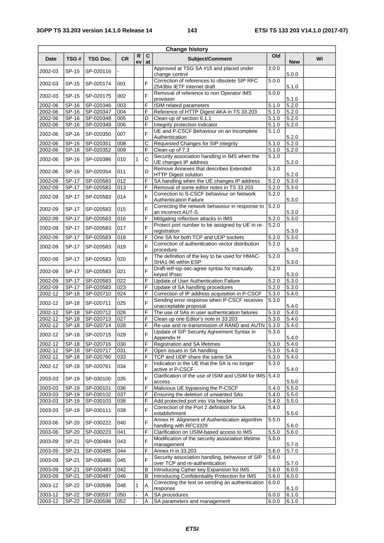
ETSI
ETSI TS 133 203 V14.1.0 (2017-07)1433GPP TS 33.203 version 14.1.0 Release 14
Change history
Date TSG # TSG Doc. CR Rev
Cat Subject/Comment Old
New WI
2002-03 SP-15 SP-020116 - Approved at TSG SA #15 and placed under change control
2.0.0 5.0.0
2002-03 SP-15 SP-020174 001 F Correction of references to obsolete SIP RFC 2543bis IETF internet draft
5.0.0 5.1.0
2002-03 SP-15 SP-020175 002 F Removal of reference to non Operator IMS provision
5.0.0 5.1.0
2002-06 SP-16 SP-020346 003 F ISIM related parameters 5.1.0 5.2.0 2002-06 SP-16 SP-020347 004 F Reference of HTTP Digest AKA in TS 33.203 5.1.0 5.2.0 2002-06 SP-16 SP-020348 005 D Clean-up of section 6.1.1 5.1.0 5.2.0 2002-06 SP-16 SP-020349 006 F Integrity protection indicator 5.1.0 5.2.0
2002-06 SP-16 SP-020350 007 F UE and P-CSCF Behaviour on an Incomplete Authentication
5.1.0 5.2.0
2002-06 SP-16 SP-020351 008 C Requested Changes for SIP integrity 5.1.0 5.2.0 2002-06 SP-16 SP-020352 009 F Clean-up of 7.3 5.1.0 5.2.0
2002-06 SP-16 SP-020386 010 1 C Security association handling in IMS when the UE changes IP address
5.1.0 5.2.0
2002-06 SP-16 SP-020354 011 D Remove Annexes that describes Extended HTTP Digest solution
5.1.0 5.2.0
2002-09 SP-17 SP-020583 012 F SA handling when the UE changes IP address 5.2.0 5.3.0 2002-09 SP-17 SP-020583 013 F Removal of some editor notes in TS 33.203 5.2.0 5.3.0
2002-09 SP-17 SP-020583 014 F Correction to S-CSCF behaviour on Network Authentication Failure
5.2.0 5.3.0
2002-09 SP-17 SP-020583 015 F Correcting the network behaviour in response to an incorrect AUT-S
5.2.0 5.3.0
2002-09 SP-17 SP-020583 016 F Mitigating reflection attacks in IMS 5.2.0 5.3.0
2002-09 SP-17 SP-020583 017 F Protect port number to be assigned by UE in re-registration
5.2.0 5.3.0
2002-09 SP-17 SP-020583 018 F One SA for both TCP and UDP sockets 5.2.0 5.3.0
2002-09 SP-17 SP-020583 019 F Correction of authentication vector distribution procedure
5.2.0 5.3.0
2002-09 SP-17 SP-020583 020 F The definition of the key to be used for HMAC-SHA1-96 within ESP
5.2.0 5.3.0
2002-09 SP-17 SP-020583 021 F Draft-ietf-sip-sec-agree syntax for manually keyed IPsec
5.2.0 5.3.0
2002-09 SP-17 SP-020583 022 F Update of User Authentication Failure 5.2.0 5.3.0 2002-09 SP-17 SP-020583 023 F Update of SA handling procedures 5.2.0 5.3.0 2002-12 SP-18 SP-020710 024 F Correction of IP address acquisition in P-CSCF 5.3.0 5.4.0
2002-12 SP-18 SP-020711 025 F Sending error response when P-CSCF receives unacceptable proposal
5.3.0 5.4.0
2002-12 SP-18 SP-020712 026 F The use of SAs in user authentication failures 5.3.0 5.4.0 2002-12 SP-18 SP-020713 027 F Clean up one Editor’s note in 33.203 5.3.0 5.4.0 2002-12 SP-18 SP-020714 028 F Re-use and re-transmission of RAND and AUTN 5.3.0 5.4.0
2002-12 SP-18 SP-020715 029 F Update of SIP Security Agreement Syntax in Appendix H
5.3.0 5.4.0
2002-12 SP-18 SP-020716 030 F Registration and SA lifetimes 5.3.0 5.4.0 2002-12 SP-18 SP-020717 031 F Open issues in SA handling 5.3.0 5.4.0 2002-12 SP-18 SP-020760 033 F TCP and UDP share the same SA 5.3.0 5.4.0
2002-12 SP-18 SP-020761 034 F Indication in the UE that the SA is no longer active in P-CSCF
5.3.0 5.4.0
2003-03 SP-19 SP-030100 035 F Clarification of the use of ISIM and USIM for IMS access
5.4.0 5.5.0
2003-03 SP-19 SP-030101 036 F Malicious UE bypassing the P-CSCF 5.4.0 5.5.0 2003-03 SP-19 SP-030102 037 F Ensuring the deletion of unwanted SAs 5.4.0 5.5.0 2003-03 SP-19 SP-030103 038 F Add protected port into Via header 5.4.0 5.5.0
2003-03 SP-19 SP-030111 039 F Correction of the Port 2 definition for SA establishment
5.4.0 5.5.0
2003-06 SP-20 SP-030222 040 F Annex H: Alignment of Authentication algorithm handling with RFC3329
5.5.0 5.6.0
2003-06 SP-20 SP-030223 041 F Clarification on USIM-based access to IMS 5.5.0 5.6.0
2003-09 SP-21 SP-030484 043 F Modification of the security association lifetime management
5.6.0 5.7.0
2003-09 SP-21 SP-030485 044 F Annex H in 33.203 5.6.0 5.7.0
2003-09 SP-21 SP-030486 045 F Security association handling, behaviour of SIP over TCP and re-authentication
5.6.0 5.7.0
2003-09 SP-21 SP-030483 042 B Introducing Cipher key Expansion for IMS 5.6.0 6.0.0 2003-09 SP-21 SP-030487 046 B Introducing Confidentiality Protection for IMS 5.6.0 6.0.0
2003-12 SP-22 SP-030596 048 1 A Correcting the text on sending an authentication response
6.0.0 6.1.0
2003-12 SP-22 SP-030597 050 - A SA procedures 6.0.0 6.1.0 2003-12 SP-22 SP-030598 052 - A SA parameters and management 6.0.0 6.1.0

ETSI
ETSI TS 133 203 V14.1.0 (2017-07)1443GPP TS 33.203 version 14.1.0 Release 14
Change history
Date TSG # TSG Doc. CR Rev
Cat Subject/Comment Old
New WI
2003-12 SP-22 SP-030599 054 - A Reject or discard of messages 6.0.0 6.1.0 2003-12 SP-22 SP-030600 056 - A Correcting the SA handling procedures 6.0.0 6.1.0 2003-12 SP-22 SP-030601 057 - F Terminology alignment 6.0.0 6.1.0
2003-12 SP-22 SP-030603 059 - D Removing anti-replay requirement from Confidentiality clause
6.0.0 6.1.0
2003-12 SP-22 SP-030604 061 - A Ensuring the correct RAND is used in synchronization failures
6.0.0 6.1.0
2003-12 SP-22 SP-030605 063 - A Network behaviour when a new REGISTER is challenged during an on going authentication
6.0.0 6.1.0
2004-03 SP-23 SP-040153 064 - B Addition of AES transform 6.1.0 6.2.0
2004-03 SP-23 SP-040154 065 - B Deploying TLS (sips:) for interoperation between IMS and non-IMS network
6.1.0 6.2.0
2004-06 SP-24 SP-040372 066 - F Correction on IMS confidentiality protection 6.2.0 6.3.0
2004-06 SP-24 SP-040373 067 - F SIP Privacy mechanism when IMS interworking with non-IMS (foreign) network
6.2.0 6.3.0
2004-09 SP-25 SP-040618 069 - A Deletion of old authentication vectors in S-CSCF after re-synchronization
6.3.0 6.4.0
2004-09 SP-25 SP-040618 071 - F SIP Privacy mechanism when IMS interworking with non-IMS (foreign) network
6.3.0 6.4.0
2004-09 SP-25 SP-040618 072 - F IMS Service Profile is independent from Implicit Registration Set
6.3.0 6.4.0
2004-12 SP-26 SP-040854 075 1 D Editorial corrections 6.4.0 6.5.0 2005-03 SP-27 SP-050137 077 3 F Addition of reference to early IMS security TR 6.5.0 6.6.0 2005-06 SP-28 SP-050261 080 1 F Description of 2xx Auth_Ok message 6.6.0 6.7.0 IMS-ASEC 2005-09 SP-29 SP-050543 0082 - A Corrections on Network hiding 6.7.0 6.8.0 IMS-SEC
2005-09 SP-29 SP-050544 0084 - A Clarification of the authentication failure procedures
6.7.0 6.8.0 IMS-SEC
2005-09 SP-29 SP-050545 0086 1 A Correction of handling of IMPUs by the P-CSCF 6.7.0 6.8.0 IMS-SEC
2005-09 SP-29 SP-050562 0087 - F Correction of an Inconsistency Between Annex H and RFC3329
6.7.0 6.8.0
TEI6
2005-12 SP-30 SP-050764 0088 - F Correction of text on negotiation of confidentiality algorithms
6.8.0 6.9.0 IMS2
2005-12 SP-30 SP-050844 0089 3 B Extension of scope to encompass TISPAN NGN by addition of normative annex
6.8.0 7.0.0
FBI
2006-03 SP-31 SP-060060 0090 - F Change of terminology to use UE instead of mobile
7.0.0 7.1.0 FBI
2006-03 SP-31 SP-060060 0091 - B Enabling NAT traversal for signaling messages in the IMS access security framework
7.0.0 7.1.0 FBI-ISE
2006-06 SP-32 SP-060383 0092 - F Correction to the description of network hiding 7.1.0 7.1.0 FBI 2006-09 SP-33 SP-060495 0094 - A Correction of SIP Privacy reference errors 7.2.0 7.3.0 TEI6 2006-09 SP-33 SP-060503 0095 - D Removal of editor’s note 7.2.0 7.3.0 IMS-SE
2006-09 SP-33 SP-060489 0098 - A Check for duplicate (IP address, port) pairs also in re-registrations
7.2.0 7.3.0 IMS-SE
2006-09 SP-33 SP-060503 0099 - F Removing Confidentiality indication from SM8 7.2.0 7.3.0 IMS
2006-12 SP-34 SP-060805 0100 2 C Clarification to pseudo randomisation of port numbers
7.3.0 7.4.0
FBI-PCBL
2006-12 SP-34 SP-060809 0101 1 F Clarification on the usage of NDS/AF 7.3.0 7.4.0 NDSAFTLS
2007-03 SP-35 SP-070152 0104 2 C Handling of unprotected messages in IMS emergency case
7.4.0 7.5.0
FBI-ISE (IMS-SE)
2007-06 SP-36 SP-070329 0106 1 D Correction of several description mistakes 7.5.0 7.6.0 IMS 2007-09 SP-37 SP-070595 0107 2 A Authentication failure handling in IMS 7.6.0 7.7.0 IMS-SE
2007-09 SP-37 SP-070595 0105 5 B Update to procedures to allow SIP Digest and TLS in IMS
7.7.0 8.0.0
FBI-PCBL-Security
2007-10 - - - - - Correction of implementation of CR0105 rev 5 8.0.0 8.0.1 -
2007-12 SP-38 SP-070786 0114 1 A Correction of Handling unprotected error messages
8.0.1 8.1.0 TEI8
2007-12 SP-38 SP-070786 0115 1 C Addition to use of TLS for Authentication of Non-REGISTERs
8.0.1 8.1.0
PktCbl-Sec
2007-12 SP-38 SP-070786 0110 2 C Enhancements to Digest Procedures for Authentication of Non-REGISTERs
8.0.1 8.1.0
FBI-PCBL-Security
2007-12 SP-38 SP-070927 0117 2 C Informative Annex on use of authentication methods for non-registration messages
8.0.1 8.1.0
PktCbl-Sec
2008-03 SP-39 SP-080138 0123 1 C Stage 2 text on place for nonce generation 8.1.0 8.2.0 PktCbl-Sec
2008-03 SP-39 SP-080138 0124 2 B Support for dynamic SIP Digest password change
8.1.0 8.2.0 PktCbl-Sec
2008-03 SP-39 SP-080139 0122 1 A Correction of integrity protection indicator 8.1.0 8.2.0 TEI8
2008-03 SP-39 SP-080170 0125 2 B Inclusion of NASS-IMS-bundled authentication scheme in Common IMS
8.1.0 8.2.0
IMS-Sec

ETSI
ETSI TS 133 203 V14.1.0 (2017-07)1453GPP TS 33.203 version 14.1.0 Release 14
Change history
Date TSG # TSG Doc. CR Rev
Cat Subject/Comment Old
New WI
2008-03 SP-39 SP-080170 0127 1 B Co-existence of authentication schemes: how can IMS network entities enforce that Digest is not used over 3GPP access?
8.1.0
8.2.0 IMS-Sec
2008-03 SP-39 SP-080211 0129 3 B Co-existence of authentication schemes – Resolution of editor’s notes
8.1.0 8.2.0
IMS-Sec
2008-06 SP-40 SP-080264 0128 1 C Authentication of non-registration messages in IMS: relation of SIP Digest proxy authentication and IP address check
8.2.0
8.3.0 PktCbl-Sec
2008-06 SP-40 SP-080264 0138 1 C Storage of old passwords in the S-CSCF to avoid password change synchronisation problems
8.2.0
8.3.0 PktCbl-Sec
2008-06 SP-40 SP-080268 0126 3 B Introduction of support for 3GPP2 IMS Access Security
8.2.0 8.3.0
IMS-Sec
2008-06 SP-40 SP-080265 0137 - F Clarification of usage of NULL encryption and TLS
8.2.0 8.3.0 PktCbl-Sec
2008-09 SP-41 SP-080544 0145 1 C Resolution of Editor's note on 3GPP2 NDS requirement
8.3.0 8.4.0
IMS-Sec
2008-09 SP-41 SP-080544 0144 - F Removal of Editor's note in Annex P.4.2 8.3.0 8.4.0 IMS-Sec
2008-09 SP-41 SP-080544 0141 1 F Updates to stage 2 description of NASS-IMS bundled authentication
8.3.0 8.4.0 IMS-Sec
2008-09 SP-41 SP-080544 0140 1 F Correction of description of HSS tasks 8.3.0 8.4.0 IMS-Sec
2008-09 SP-41 SP-080485 0143 - B New normative Annex on GPRS-IMS-Bundled Authentication (GIBA)
8.3.0 8.4.0
IMS-Sec
2008-09 SP-41 SP-080485 0142 - F Changes to TS 33.203 due to a new normative Annex on GIBA
8.3.0 8.4.0 IMS-Sec
2008-12 SP-42 SP-080742 148 1 F Usage of SIP digest and NBA values between the S-CSCF and the HSS
8.4.0 8.5.0 IMS-Sec
2008-12 SP-42 SP-080742 149 2 F Consistent handling of the integrity-protected flag and Inclusion of authentication procedures related to ICS
8.4.0
8.5.0 IMS-Sec
2008-12 SP-42 SP-080888 151 4 F Correcting the IMC text 8.4.0 8.5.0 IMS-Sec 2008-12 SP-42 SP-080742 152 - F Editorial corrections in Annex P3 and P.4.2 8.4.0 8.5.0 IMS-Sec
2008-12 SP-42 SP-080742 153 - F Removal of SIP Digest Authentication Vector Editor’s Note
8.4.0 8.5.0
IMS-Sec
2008-12 SP-42 SP-080742 154 - F Usage of AVs for authentication of Register and Non-Register messages
8.4.0 8.5.0 IMS-Sec
2008-12 SP-42 SP-080742 155 - F ISIM terminology 8.4.0 8.5.0 IMS-Sec
2009-03- SP-43 SP-090142 156 - B Solution for NAT traversal in GPRS-IMS-Bundled Authentication
8.5.0 9.0.0
TEI9
2009-12 SP-44 SP-090271 158 - A Correction of wrong message name in annex N (Rel-8)
9.0.0 9.1.0 IMS-Sec
2009-12 SP-44 SP-090271 161 1 A Removing Editor’s note from Annex T 9.0.0 9.1.0 IMS-Sec
2009-09 SP-45 SP-090521 163 1 A Removal of editor’s note on Proxy-Authentication Info header
9.1.0 9.2.0
IMS-Sec
2009-09 SP-45 SP-090521 165 1 A Aligning NBA and GIBA procedures with stage 3 9.1.0 9.2.0 TEI8 2009-09 SP-45 SP-090521 166 1 A Removal of TLS profile editor's note. 9.1.0 9.2.0 TEI8 2009-09 SP-46 SP-090816 0170 - A Removing editor’s notes in Annex P 9.2.0 9.3.0 IMS-Sec
2009-09 SP-46 SP-090816 0169 - A Removal of editor’s note on draft-ieft-sip-outbound
9.2.0 9.3.0 IMS-Sec
2009-09 SP-46 SP-090866 0171 - F Correction of erroneous interface name 9.2.0 9.3.0 IMS-Sec 2009-09 SP-46 SP-090858 0174 1 F X.509 certificate profile alignment 9.2.0 9.3.0 TEI9 2010-06 SP-48 SP-100251 0178 - F X.509 Certificate profile aligment 9.3.0 9.4.0 TEI9
2010-06 SP-48 SP-100378 0177 - F SIP Digest without Authorization header in first REGISTER message
9.4.0 10.0.0 TEI9
2010-06 SP-48 SP-100368 0179 - F X.509 Certificate profile aligment 9.4.0 10.0.0 TEI10
2010-10 SP-49 SP-100478 184 1 A Correction of SIP digest credential wording in N.2.5
10.0.0 10.1.0
TEI9
2010-10 SP-49 SP-100474 185 2 C IPsec alignment 10.0.0 10.1.0 TEI10
2010-10 SP-49 SP-100482 186 1 C Introduction of reference to TS 33.310 for TLS profile into TS 33.203
10.0.0 10.1.0 TEI10
2010-12 SP-50 SP-100714 187 1 F Clarification of GIBA restrictions 10.1.0 10.2.0 TEI10 2010-12 SP-50 SP-100725 188 1 C IPsec alignment 10.2.0 11.0.0 TEI11
2012-03 SP-55 SP-120039 189 - D Editorial correction of scope in Annex S on 3GPP2 access
11.0.0 11.1.0
SEC11
2012-06 SP-56 SP-120338 190 1 C Update for use with EPS 11.2.0 12.0.0 SEC12 2012-06 SP-56 SP-120338 191 1 F Editorial Corrections and cleaning 11.2.0 12.0.0 SEC12 2012-09 SP-57 SP-120602 192 3 C TLS enhancements for IMS signaling security 12.0.0 12.1.0 SEC12
2013-06 SP-60 SP-130254 198 - B Specification of Tunnelling of UE Services over Restrictive Access Networks - IMS 12.1.0 12.2.0 TURAN
2013-09 SP-61 SP-130404 199 1 B Firewall traversal for IMS services based on ICE 12.2.0 12.3.0 TURAN

ETSI
ETSI TS 133 203 V14.1.0 (2017-07)1463GPP TS 33.203 version 14.1.0 Release 14
Change history
Date TSG # TSG Doc. CR Rev
Cat Subject/Comment Old
New WI
SP-130402 200 - D Clarification regarding NAT and GIBA SEC12
SP-130404 201 1 F Correction of Specification of Tunnelling of UE Services over Restrictive Access Networks - IMS case
TURAN
SP-130404 202 - D Missing caption and hanging paragraph TURAN 2012-12 SP-62 SP-130665 204 1 F Incorrect reference for keep-alive mechanism 12.3.0 12.4.0 TURAN
2014-03 SP-63 SP-140022 205 2 F The mechanism for the IMS client to determine when TURN over TCP/TLS can be used 12.4.0 12.5.0 TURAN
2014-06 SP-64 SP-140312
208 1 B Description of scenario 2 in new Annex on WebRTC
12.5.0 12.6.0 IMS_WebRTC
209 1 B Description of scenario 3 in new Annex on WebRTC
211 1 B Skeleton for new Annex on WebRTC
212 2 B WebRTC IMS Client registration using SIP Digest
213 1 B New Annex on WebRTC with re-use of IMS AKA scheme for WIC authentication
2014-09 SP-65
SP-140593
216 1 F Correction to 33.203 of TLS cipher suites profile for IMS access security
12.6.0 12.7.0
TEI12 217 1 F Correction to 33.203 of TLS profile regarding renegotiation
218 1 F Correction and clarification of SPI information in Security-client header (R12)
SP-140588
221 1 F Verification of WIC may not require CORS
IMS_WebRTC
222 - D Editorial correction relating to WebRTC registration scenarios
223 - F Terminology in WebRTC 224 1 F WIC authentication with IMS AKA 225 1 F Effects on key theft when using IMS-AKA
2014-12 SP-66 SP-140825
227 - F Addition in Annex P of IMS AKA over TLS for WebRTC
12.7.0 12.8.0 IMS_WebRTC
228 1 F TLS details for WebRTC with IMS AKA 229 - F Clarification of term authorization entity
230 1 F Restructuring of TS 33.203 to clarify how eP-CSCF obtains authorization information
231 1 F Correction of reference
2015-09 SP-69
SP-150477 240 1 F Adding TLS Reference in TS 33.203 Annex W 12.8.0 12.9.0
TURAN-SA3, TEI12
SP-150486 241 1 F Trans mode of NAT traversal in TS 33.203v12.8.0 SEC12
SP-150474
235 2 B Overview of solutions for TURN credential provisioning and Authentication
12.9.0 13.0.0 eWebRTCi 236 2 B Solution for WebRTC TURN credential
provisioning and authentication with eP-CSCF
238 - B Solution for TURN credential provisioning and Authentication using OAuth 2.0 Access tokens
239 - B Supporting Class of Users (WebRTC scenario 4) 2015-12 SP-70 SP-150731 244 2 F Updating IMS security profiles in TS 33.203 13.0.0 13.1.0 SEC13
Change history Date Meeting TDoc CR Rev Cat Subject/Comment New
version 2017-03 SA#75 Promotion to Release 14 without technical change 14.0.0 2017-06 SA#76 SP-170426 0246 - A Setting the salt value in UE and P-CSCF when using AES-
GCM/AES-GMAC in IPSec ESP in IMS access security 14.1.0

ETSI
ETSI TS 133 203 V14.1.0 (2017-07)1473GPP TS 33.203 version 14.1.0 Release 14
History
Document history
V14.0.0 April 2017 Publication
V14.1.0 July 2017 Publication