trunnion ball valve · 2020-03-26 · trunnion mounted ball valves a large trunnion design ensures...
TRANSCRIPT

TRUNNION BALL VALVE

Trunnion Mounted Ball Valves
A large trunnion design ensures
central positioning under the highest
working pressure. Independent
floating spring loaded seats provide
a tight seal even at low differential
pressures. Service and maintenance
is simplified with a bolted body
design incorporating double o-
rings or a combination of o-rings
and gaskets, suitable for buried or
above ground installation. Service
and maintenance
Three-piece body design
Double block and bleed
Self relieving seat
Double piston seat
Trunnion supported design reduces operating torque
Antistatic device for grounding of the ball, stem and body
O-rings plus firesafe stem packing prevent leakage
Corrosion resistant low friction bearings
Inconel® seat springs provide upstream and downstream sealing
Stainless steel sealant injection fittings for emergency stemor seal sealing
Direct mount top works pad for actuator or gear operator
6" & larger valves are equipped with lifting lugs
Locking device (lock not included)
Anti-blowout trunnion stem design
Constructional Variation available
Features
DesignClass/Size
150# 300# 600# 900# 1500# 2500#
2-Piece 2"~12" 2"~12" 2"~12" 2"~12"
3-Piece 2"~56" 2"~56" 2"~56" 2"~36" 2"~24" 2"~12
01

The following list contains the most important applicable standards for ball valves. Redstar valves may be designed, manufactured and tested in accordance with other international standards on request.
API-American Petroleum Institute
Consult factory for details.
British Standards
Applicable Standards
Spec. Q1
Spec. 6D
Specification for pipeline valves.
Std. 607
Fire test for soft seated quarter-
turn valves.
Spec. 6FA
Specification for fire testing of
valves.
Std. 598
Valve inspection and test.
Std. 605
Large diameter carbon steel
flanges.
B 16.5
Steel pipe flanges and flanged
fittings.
B 16.10
Face-to-face and end-to-end
dimensions of ferrous valves.
B 16.25
Butt welding ends.
B 16.34
Steel valves-flanged and butt
welding ends.
B 31.3
Chemical plant and petroleum
refinery piping.
B 31.4
Liquid petroleum transportation
piping systems.
B 31.8
Gas transmission and
distribution piping systems.
Face-to-face, center-to-face,
end-to-end and center-to-end
dimensions of flanged and butt
welding end steel valves for the
petroleum, petrochemical and
allied industries.
BS 1503
Specification for steel forgings for
pressure purposes.
BS 1504
Specification for steel castings for
pressure purposes.
BS 2080
ASME / ANSI-American National Standard Institute
ASTM-American Society for Testing Materials
For use in H2S containing
environments in oil and gas
production.
ISO 9001: 2008
Quality systems-Model for quality
assurance in design /
development, production,
installation and servicing.
ISO 5211
Topworks mounting dimensions
ISO 15156
ISO-International Organization for Standardization
MSS-Manufacturers Standardization Society
Standard finishes for contact
faces of pipe flanges and
connecting-end flanges of
valves and fittings.
NACE MR0175ISO 15156
General principles for
cracking
resistant materials in H2S
containing environments in
oil & gas production.
CSA Z245.15-2009Standard for steel valves for
intended use in oil or gas
pipeline systems.
CSA Z662-07Oil and gas pipeline systems.
SP 6
SP 25
SP 45Bypass and drain connection
standard.
Standard marking system for
valves, fittings, flanges and
unions.
Hydrogen Sulfide (H2S En-vironments)
CSA-Canadian Standards Association
02

The ball is fixed by trunnion (size 4”& smaller) or trunnion
support (size 6” & larger), and the seat rings are floating,
free to move against the ball along the valve centerline.
The trunnion / trunnion support together with bearings
adsorb the side load created by the pressure acting on the
ball. At low pressure, the seat tight sealing is ensured by
the preload of the springs acting on the seat rings. Along
with the pressure increasing, the process medium pressure
pushes the seat rings against the ball to provide additional
load for tight sealing.
The ball and stem are independent with each other to
minimize the effect of the side thrust generated by the
pressure acting on the ball.
Design Features
Trunnion Mounted Ball Valves
Mechanical stops are equipped on all valves to ensure the
ball is never to be over rotated.
When valves are used under high pressure gas
applications, e.g. hydrocarbon gas service under class 600
and above, the gas may be absorbed into the molecular
structure of elastomeric O-rings. If the valve is subjected to
sudden decompression, the O-rings may be destroyed by
the rapidly expanded gas. To avoid this possibility, special
AED O-rings or Lip seals, suitable for such service
conditions, are available on request.
Accurate machining of stem, gland and body sealing surfaces with double sealing (O-ring primary seal plus
graphite gasket seal) ensure the low emission which is complying with the most severe pollution-control
regulations. The test certifications are available on request.
General Design
Ball Seat Alignment
AED O-Ring
Environment Friendly Valve
03

Blow-out Proof Stem
Anti-static Device
The stem is made separately from the ball with integral T-type round shoulder, retained by gland. (other designs
are available on request).(Fig. 1)
Spring plus graphite type anti- s t a t i c device are
applied between the ball, stem, gland Stem Fire
Safe Packing (Graphite) O-ring Stem Top Flange
Gland Flangeflange and body, to keep the electrical
continuity between all the metallic components, and
ensure the resistance lower than the most severe
service requirement.(Fig. 1)
a) External leakage prevention
All the possible external leakage point between stem
and gland flange, gland flange and body, body and
adapter are sealed with primary O-ring then
secondary graphite gasket. When fire burned out the
primary O-ring seal, the secondary graphite gasket
seal still can prevent the process medium from
external leakage.(Fig. 2)
b) Internal leakage prevention
When fire burned out the primary O-ring seal between the floating seat ring and adapter, also the seat insert
between seat ring and ball, the secondary graphite seal between seat ring and adapter, and seat ring & ball
metal to metal contact preloaded by spring will minimize the internal process medium leakage. (Fig. 3, 4)
Before Fire After Fire
Fire Safe
Fig.1
Fig.2
Fig.3 Fig.4
04

Seat Design Features
Trunnion Mounted Ball Valves
Standard seat design is primary soft seal, and secondary metal to metal seal. Seat insert is designed as pressed-
in type which is easy for maintenance.(Fig. 5) Optional design with primary metal to metal seal and secondary
soft seal seat design is also available upon request.(Fig. 6)
a) Standard: Single Piston Effect Seats (Self Relieving Seats)
Medium pressure, both upstream and downstream, creates a resultant thrust to the seat rings against the ball to
assure tight sealing; Medium pressure acting in the body cavity creates a resultant thrust to push the seat rings
away from the ball.
The single piston design permits the automatic release of any over pressure in the body cavity when the valve is
in the fully open or fully closed position. (Fig. 7, 8)
b) Option 1: Double Piston Effect Seats
Medium pressure, both upstream and downstream as well as in the body cavity, creates a resultant thrust that
pushes the seat rings against the ball. Valves with double piston effect seat rings require a cavity pressure relief
device to reduce the build-up of over pressure in the body cavity. (Fig. 9, 10)
c) Option 2: Combination Seats
Combination seats design is available on request. That is a standard seat design used for upstream side and a
double piston effect seats design used for downstream. The advantage is it can reach double piston effect seats
design function without cavity pressure relief device to saves the cost, meanwhile only need a little care to install
valve per flow direction arrow. (Fig. 7, 10)
Fig.5 Fig.6
Fig.7 Fig.8
Fig.9 Fig.10
05
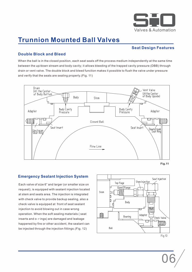
Double Block and Bleed
When the ball is in the closed position, each seat seals off the process medium independently at the same time
between the up/down stream and body cavity; it allows bleeding of the trapped cavity pressure (DBB) through
drain or vent valve. The double block and bleed function makes it possible to flush the valve under pressure
and verify that the seats are sealing properly.(Fig. 11)
Emergency Sealant Injection System
Each valve of size 6” and larger (or smaller size on
request), is equipped with sealant injection located
at stem and seats area. The injection is integrated
with check valve to provide backup sealing, also a
check valve is equipped at front of seat sealant
injection to avoid blowing out in case wrong
operation. When the soft sealing materials ( seat
inserts and o- r ings) are damaged and leakage
happened by fire or other accident, the sealant can
be injected through the injection fittings.(Fig. 12)
Trunnion Mounted Ball ValvesSeat Design Features
Fig.11
06

Feature
No Part Name
Main Part Name
2PC / 3PC Body Casted Trunnion Mounted Ball Valve
Specifications
Design
Face to Face
End To End
End Flange
BW End
Test
Fire Safe Test
Special
ASME B16.34/API6D
ASME B16.10/API 6D
ASME B16.10/API 6D
ASME B16.50/ B16.47A
ASME B16.25
API 6D
API 607/API 6FA
NACE MR 0175
Size: 2"-24"
Class: 150~900
Two pieces / three pieces casted body
Trunnion Mounted Ball, Full & Reduced Bore
Anti-static Device
Blow-out Proof Stem
Double Block and Bleed
Fire Safe Design
Emergency Sealant Injector (6" & Larger)
Vent Valve (6" & Larger)
Lifting Lugs & Supporting Feet ( 8" & Larger)
Seat Pocket SS overlay ( Optional)
Seals Area ENP Coated
1
2
3
4
5
6
7
8
9
10
11
12
13
14
15
16
17
18
19
20
21
22
O-ring
Spring
Seat ring
Seat ring
Body
Stud
O ring
Trunnion
Body Gasket
Nut
Stud
Ball
Bonnet
Stem
Thrust Washer
Soliding Bearing
Cover
Packing
Flange Gland
Vent
Injection
Drain
07

Feature
No Part Name
Main Part Name
Specifications
Design
Face to Face
End To End
End Flange
BW End
Test
Fire Safe Test
Special
1
2
3
4
5
6
7
8
9
10
11
12
13
14
15
16
17
18
19
20
21
22
3PC Body Forged Trunnion Mounted Ball Valve
Size: 2"-48"
Class: 150~2500
Three Pieces Forged Steel Body
Trunnion Mounted Ball, Full & Reduced Bore
Anti-static Device
Blow-out Proof Stem
Double Block and Bleed
Fire Safe Design
Emergency Sealant Injector (6" & Larger)
Vent Valve (6" & Larger)
Lifting Lugs & Supporting Feet ( 8" & Larger)
Seat Pocket SS overlay ( Optional)
Seals Area ENP Coated
ASME B16.34/API6D
ASME B16.10/API 6D
ASME B16.10/API 6D
ASME B16.50/ B16.47A
ASME B16.25
API 607/API 6FA
NACE MR 0175
O-ring
Spring
Seat ring
Seat ring
Body
Stud
O ring
Trunnion
Body Gasket
Nut
Stud
Ball
Bonnet
Stem
Thrust Washer
Soliding Bearing
Cover
Packing
Flange Gland
Vent
Injection
Drain
08
API 6D/API 598

Feature
Main Part Name
Specifications
Design
Face to Face
End To End
End Flange
BW End
Test
Fire Safe Test
Special
3 PC Fully Welded Trunnion mounted Ball Valve
Size: 2"-48"
Class: 150~2500
Three Pieces Forged Steel Body
Trunnion Mounted Ball, Full & Reduced Bore
Anti-static Device
Blow-out Proof Stem
Double Block and Bleed
Fire Safe Design
Emergency Sealant Injector (6" & Larger)
Vent Valve (6" & Larger)
Lifting Lugs & Supporting Feet ( 8" & Larger)
Seat Pocket SS overlay ( Optional)
Seals Area ENP Coated
ASME B16.34/API6D
ASME B16.10/API 6D
ASME B16.10/API 6D
ASME B16.50/ B16.47A
ASME B16.25
API 6D/API 598
API 607/API 6FA
NACE MR 0175
09
NO:
1
2
3
4
5
6
7
8
9
10
11
12
13
14
15
16
17
18
19
PART NAME
SEAL RING
SUPPORT PLATE
BODY
BUSHING
LOWER GASKET
“O”RINR
PIN
BONNET
SEAT SPRING
BALL
AEAT RETAINER
SEAT RING
STEM
LOWER GASKET
STUFFING BOX
PACKING
FLANGE GLAND
VENT/DRAIN
INJECTION
Feature
No Part NameMain Part Name
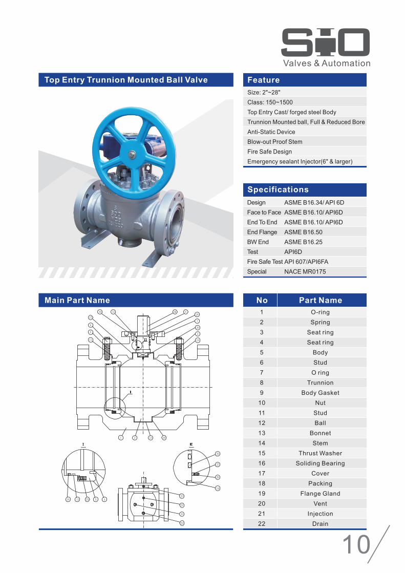
Top Entry Trunnion Mounted Ball Valve
Size: 2"~28"
Class: 150~1500
Top Entry Cast/ forged steel Body
Trunnion Mounted ball, Full & Reduced Bore
Anti-Static Device
Blow-out Proof Stem
Fire Safe Design
Emergency sealant Injector(6" & larger)
Specifications
Design
Face to Face
End To End
End Flange
BW End
Test
Fire Safe Test
Special
ASME B16.34/ API 6D
ASME B16.10/ API6D
ASME B16.10/ API6D
ASME B16.50
ASME B16.25
API6D
API 607/API6FA
NACE MR0175
1
2
3
4
5
6
7
8
9
10
11
12
13
14
15
16
17
18
19
20
21
22
O-ring
Spring
Seat ring
Seat ring
Body
Stud
O ring
Trunnion
Body Gasket
Nut
Stud
Ball
Bonnet
Stem
Thrust Washer
Soliding Bearing
Cover
Packing
Flange Gland
Vent
Injection
Drain
10

3PC Body Forged Trunnion Mounted Ball ValveDimensions and Weights
Reduced Bore Class 150
51
76
102
152
203
254
305
337
387
438
489
540
591
635
686
737
781
832
876
978
1022
1168
178
203
229
394
457
533
610
686
762
864
914
991
1067
1143
1245
1295
1372
1473
1524
1727
1987
2120
155
191
211
231
282
336
373
413
457
501
551
600
635
710
760
800
840
890
930
1010
1598
1722
85
110
130
160
235
290
315
345
383
435
495
555
590
620
670
710
745
775
805
900
900
1040
350
400
450
*305
*406
*406
*406
*406
*600
*600
*600
*600
*700
*700
*760
*760
*760
*760
*760
*760
*760
*760
30
60
92
190
345
495
705
859
1020
1440
1918
2352
2803
3200
4045
4820
5490
6704
7615
10271
12200
18400
Size
in mm mm mm mmmmd L H1 H2 W Weight
Full Bore Class 150
2
3
4
6
8
10
12
14
16
18
20
22
24
26
28
30
32
34
36
40
42
48
38
51
76
102
152
203
254
254
305
305
337
337
387
387
438
438
489
540
591
591
635
686
737
832
2*1-1/2
3*2
4*3
6*4
8*6
10*8
12*10
14*10
14*12
16*12
16*14
18*14
18*16
20*16
20*18
22*18
24*20
26*22
28*24
30*24
32*26
34*28
36*30
40*34
51
76
102
152
203
254
305
337
337
387
387
438
438
489
489
540
591
635
686
737
781
832
876
978
178
203
229
394
457
533
610
686
686
762
762
864
864
914
914
991
1067
1143
1245
1295
1372
1473
1524
1727
152
155
191
211
231
282
336
336
373
373
413
413
457
457
501
501
551
600
635
635
710
760
820
935
80
85
110
130
160
235
290
290
315
315
345
345
383
383
435
435
495
555
590
590
620
670
710
775
350
350
400
450
*305
*406
*406
*406
*406
*406
*406
*406
*600
*600
*600
*600
*600
*600
*700
*700
*700
*760
*760
*760
26
34
62
102
225
373
533
626
730
790
844
1010
1095
1115
1152
2343
2060
2215
2803
2803
4005
4445
4995
8200
KgSize d
in mmL H1 H2 W Weight
mm mm mmmm KgD
mm
2
3
4
6
8
10
12
14
16
18
20
22
24
28
30
32
34
36
40
42
48
51
76
102
152
203
254
305
337
387
438
489
540
591
686
737
781
832
876
978
1022
1168
216
283
305
403
502
568
648
762
838
914
991
1092
1143
1346
1397
1524
1626
1727
1956
2032
2170
155
191
211
229
291
340
375
417
466
506
563
605
684
770
810
850
900
940
1025
1640
1765
85
110
130
160
235
290
315
345
400
440
495
560
590
680
720
760
790
820
915
920
1070
400
450
500
*305
*406
*406
*500
*600
*600
*600
*600
*700
*760
*760
*760
*800
*800
*800
*800
*800
*800
31
69
110
211
376
540
763
900
1300
1715
2090
2220
2890
4575
5590
6240
7370
8435
11200
13000
19000
Full Bore Class 300
38
51
76
102
152
203
254
254
305
305
337
337
387
387
438
438
489
591
591
686
737
832
2*1-1/2
3*2
4*3
6*4
8*6
10*8
12*10
14*10
14*12
16*12
16*14
18*14
18*16
20*16
20*18
22*18
24*20
28*24
30*24
34*28
36*30
40*34
51
76
102
152
203
254
305
337
337
387
387
438
438
489
489
540
591
686
737
832
876
978
216
283
305
403
502
568
648
762
762
838
838
914
914
991
991
1092
1143
1346
1397
1626
1727
1956
152
155
191
211
229
291
340
340
375
375
417
417
466
466
506
506
563
684
684
770
810
900
80
85
110
130
160
235
290
315
315
360
360
400
400
420
440
440
495
590
590
680
720
790
350
400
450
500
*305
*406
*406
*406
*500
*500
*600
*600
*600
*600
*600
*600
*600
*760
*760
*760
*760
*800
30
37
74
142
253
410
580
683
830
1051
1125
1320
1530
1780
1830
2010
2220
3200
3200
4845
5590
8200
Size
in mm mm mm mmmm Kgd L H1 H2 W Weight Size d
in mmL H1 H2 W Weight
mm mm mmmm KgD
mm
Reduced Bore Class 300
* Gear Operated
Note: Redstar reserves the right to make any modifications without notice.
11

3PC Body Forged Trunnion Mounted Ball Valve
Dimensions and Weights
Reduced Bore Class 600Size
in mm mm mm mmmmd L H1 H2 W Weight
Full Bore Class 600
KgSize d
in mmL H1 H2 W Weight
mm mm mmmm KgD
mm
Full Bore Class 900LBSize
in mm mm mm mmmm Kgd L H1 H2 W Weight Size d
in mmL H1 H2 W Weight
mm mm mmmm KgD
mm
Reduced Bore Class 900LB
2
3
4
6
8
10
12
14
16
18
20
22
24
28
30
32
34
36
40
42
48
51
76
102
152
203
254
305
337
387
438
489
540
591
686
737
781
832
876
978
1022
1168
292
356
432
559
660
787
838
889
991
1092
1194
1295
1397
1549
1651
1778
1930
2083
2159
2175
2435
155
193
239
266
310
354
411
435
493
544
629
683
728
810
863
900
940
990
1070
1640
1765
85
112
140
175
250
290
345
370
420
462
515
570
610
695
735
775
820
885
935
940
1070
400
500
700
*406
*406
*600
*600
*600
*600
*700
*760
*800
*800
*800
*800
*800
*800
*800
*800
*800
*800
45
80
150
248
438
701
855
1230
1535
2135
2640
3370
3960
6060
6690
7825
8460
10650
14700
16400
24200
38
51
76
102
152
203
254
254
305
305
337
337
387
387
438
438
489
591
591
686
737
832
2*1-1/2
3*2
4*3
6*4
8*6
10*8
12*10
14*10
14*12
16*12
16*14
18*14
18*16
20*16
20*18
22*18
24*20
28*24
30*24
34*28
36*30
40*34
51
76
102
152
203
254
305
337
337
387
387
438
438
489
489
540
591
686
737
832
876
978
292
356
432
559
660
787
838
889
889
991
991
1092
1092
1194
1194
1295
1397
1549
1651
1930
2083
2159
152
155
193
239
266
310
354
354
411
411
435
435
493
493
544
544
629
728
728
810
863
940
80
85
112
140
175
250
290
345
345
370
370
410
420
440
462
462
515
610
610
695
735
820
350
400
500
700
*406
*406
*600
*600
*600
*600
*600
*600
*600
*600
*700
*700
*760
*800
*800
*800
*800
*800
40
54
99
212
304
510
794
843
910
965
1310
1520
1640
2065
2270
2430
3440
4250
4730
7200
8600
10020
2
3
4
6
8
10
12
14
16
18
20
24
28
30
34
36
51
76
102
152
203
254
305
324
375
425
473
572
667
714
810
857
368
381
457
610
737
838
965
1029
1130
1219
1321
1549
1753
1880
2159
2286
178
221
215
268
324
371
425
463
513
614
644
745
830
880
970
1030
100
125
150
215
260
305
360
390
440
500
530
630
720
755
850
930
450
600
*305
*406
*600
*600
*600
*600
*710
*760
*760
*800
*800
*800
*900
*900
52
87
160
385
560
820
1125
1610
2010
2810
3460
5497
10202
11442
17462
20154
38
51
76
102
152
203
254
254
305
305
324
375
375
425
473
572
572
667
714
2*1-1/2
3*2
4*3
6*4
8*6
10*8
12*10
14*10
14*12
16*12
16*14
18*16
20*16
20*18
24*20
28*24
30*24
34*28
36*30
51
76
102
152
203
254
305
324
324
375
375
425
473
473
572
667
714
810
857
368
381
457
610
737
838
965
1029
1029
1130
1130
1219
1321
1321
1549
1753
1880
2159
2286
152
178
221
215
268
324
371
371
425
425
463
513
513
614
644
745
745
830
880
80
100
125
150
260
305
335
360
360
390
390
440
470
500
550
630
665
750
780
400
450
600
*305
*406
*600
*600
*600
*600
*600
*600
*710
*710
*760
*760
*800
*800
*800
*800
45
56
94
226
480
650
868
1050
1310
1385
1830
2205
2735
3140
3810
7580
7981
11202
15653
* Gear Operated
Note: Redstar reserves the right to make any modifications without notice.
12
Full Bore Class 2500 Reduced Bore Class 2500
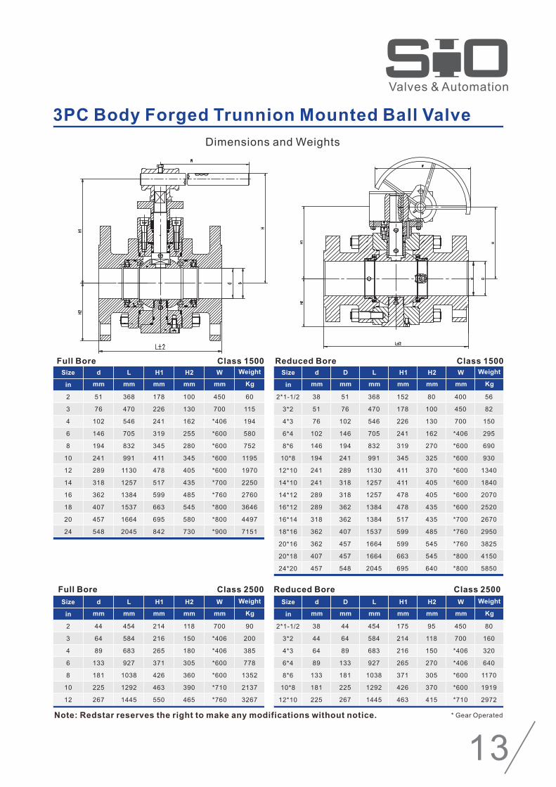
3PC Body Forged Trunnion Mounted Ball Valve
Dimensions and Weights
Full Bore Class 1500 Reduced Bore Class 1500
Size
in mm mm mm mmmm
d L H1 H2 W Weight
Kg
2
3
4
6
8
10
12
14
16
18
20
24
51
76
102
146
194
241
289
318
362
407
457
548
368
470
546
705
832
991
1130
1257
1384
1537
1664
2045
178
226
241
319
345
411
478
517
599
663
695
842
100
130
162
255
280
345
405
435
485
545
580
730
450
700
*406
*600
*600
*600
*600
*700
*760
*800
*800
*900
60
115
194
580
752
1195
1970
2250
2760
3646
4497
7151
Size d
in mm
L H1 H2 W Weight
mm mm mmmm Kg
D
mm
38
51
76
102
146
194
241
241
289
289
318
362
362
407
457
2*1-1/2
3*2
4*3
6*4
8*6
10*8
12*10
14*10
14*12
16*12
16*14
18*16
20*16
20*18
24*20
51
76
102
146
194
241
289
318
318
362
362
407
457
457
548
368
470
546
705
832
991
1130
1257
1257
1384
1384
1537
1664
1664
2045
152
178
226
241
319
345
411
411
478
478
517
599
599
663
695
80
100
130
162
270
325
370
405
405
435
435
485
545
545
640
400
450
700
*406
*600
*600
*600
*600
*600
*600
*700
*760
*760
*800
*800
56
82
150
295
690
930
1340
1840
2070
2520
2670
2950
3825
4150
5850
Size
in mm mm mm mmmm
d L H1 H2 W Weight
Kg
Size d
in mm
L H1 H2 W Weight
mm mm mmmm Kg
D
mm
2
3
4
6
8
10
12
44
64
89
133
181
225
267
454
584
683
927
1038
1292
1445
214
216
265
371
426
463
550
118
150
180
305
360
390
465
700
*406
*406
*600
*600
*710
*760
90
200
385
778
1352
2137
3267
38
44
64
89
133
181
225
2*1-1/2
3*2
4*3
6*4
8*6
10*8
12*10
44
64
89
133
181
225
267
454
584
683
927
1038
1292
1445
175
214
216
265
371
426
463
95
118
150
270
305
370
415
450
700
*406
*406
*600
*600
*710
80
160
320
640
1170
1919
2972
* Gear OperatedNote: Redstar reserves the right to make any modifications without notice.
13

Reduced Bore Class 150Size d
in mm
L H1 H2 W Weight
mm mm mmmm Kg
D
mm
Dimensions and Weights
38
51
76
102
152
203
254
254
305
305
337
337
387
387
438
489
2*1-1/2
3*2
4*3
6*4
8*6
10*8
12*10
14*10
14*12
16*12
16*14
18*14
18*16
20*16
20*18
24*20
51
76
102
152
203
254
305
337
337
387
387
438
438
489
489
591
292
356
432
559
660
787
838
889
889
991
991
1092
1092
1194
1194
1397
180
210
225
260
295
322
357
357
405
405
455
455
463
463
500
555
78
83
110
143
217
264
313
313
372
372
430
430
452
452
470
583
250
350
400
450
*305
*406
*406
*406
*406
*406
*406
*406
*600
*600
*600
*600
41
58
104
228
320
536
685
740
840
924
1070
1177
1430
1681
1850
2450
Reduced Bore Class 300Size d
in mm
L H1 H2 W Weight
mm mm mmmm Kg
D
mm
38
51
76
102
152
203
254
254
305
305
337
337
387
387
438
489
2*1-1/2
3*2
4*3
6*4
8*6
10*8
12*10
14*10
14*12
16*12
16*14
18*14
18*16
20*16
20*18
24*20
51
76
102
152
203
254
305
337
337
387
387
438
438
489
489
591
292
356
432
559
660
787
838
889
889
991
991
1092
1092
1194
1194
1397
180
210
225
260
295
330
365
365
415
415
460
460
480
480
523
585
78
83
110
143
217
264
313
313
400
400
430
430
452
452
470
583
250
400
450
500
*305
*406
*406
*406
*500
*500
*600
*600
*600
*600
*600
*600
44
62
110
243
343
559
725
798
890
1052
1120
1288
1480
1728
1960
2650
Top Entry Forged Trunnion Mounted Ball Valve
Class 150Size
in mm mm mm mmmm
d L H1 H2 W Weight
Full Bore
Kg
2
3
4
6
8
10
12
14
16
18
20
24
51
76
102
152
203
254
305
337
387
438
489
591
292
356
432
559
660
787
838
889
991
1092
1194
1397
210
225
260
295
322
357
405
455
470
500
555
600
83
110
143
217
264
313
372
430
452
470
583
594
350
400
450
*305
*406
*406
*406
*406
*600
*600
*600
*700
46
83
156
256
453
622
747
959
1220
1640
2118
2950
Class300Size
in mm mm mm mmmm
d L H1 H2 W Weight
Full Bore
Kg
2
3
4
6
8
10
12
14
16
18
20
24
51
76
102
152
203
254
305
337
387
438
489
591
292
356
432
559
660
787
838
889
991
1092
1194
1397
210
225
260
295
330
365
415
460
480
523
585
635
83
110
143
217
264
313
400
430
452
470
583
594
400
450
500
*305
*406
*406
*500
*600
*600
*600
*600
*760
49
87
164
272
479
657
783
1007
1281
1722
2224
3100
* Gear Operated
* Gear Operated
Note: Redstar reserves the right to make any modifications without notice.
14

Size
in mm mm mm mmmm
d L H1 H2 W Weight
Kg
Size
in mm mm mm mmmm
d L H1 H2 W Weight
Kg
Size
in mm mm mm mmmm
d L H1 H2 W Weight
Kg
Dimensions and Weights
2
3
4
6
8
10
12
51
76
102
152
203
254
305
292
356
432
559
660
787
838
210
225
260
295
330
370
425
83
110
143
217
264
313
400
400
500
700
*406
*406
*600
*600
52
92
173
285
504
680
819
Full Bore Class 600 Reduced Bore
2
3
4
6
8
10
12
51
76
102
152
203
254
305
368
381
457
610
737
838
965
210
225
260
295
335
377
510
83
110
143
225
270
320
415
450
600
*305
*406
*600
*600
*600
60
100
204
420
644
943
1295
Full Bore Class 900 Reduced Bore
2
3
4
6
8
10
12
51
76
102
146
194
241
289
368
470
546
705
832
991
1130
210
235
290
300
350
400
525
83
120
153
235
282
335
425
450
700
*406
*600
*600
*600
*600
69
133
256
667
865
1375
2175
Full Bore Class 1500 Reduced Bore
Top Entry Forged Trunnion Mounted Ball Valve
Note: Redstar reserves the right to make any modifications without notice.
Size d
in mm
L H1 H2 W Weight
mm mm mmmm Kg
D
mm
Size d
in mm
L H1 H2 W Weight
mm mm mmmm Kg
D
mm
Size d
in mm
L H1 H2 W Weight
mm mm mmmm Kg
D
mm
38
51
76
102
152
203
254
2*1-1/2
3*2
4*3
6*4
8*6
10*8
12*10
51
76
102
152
203
254
305
292
356
432
559
660
787
838
180
210
225
260
295
330
370
78
83
110
143
217
264
313
350
400
500
700
*406
*406
*600
46
74
120
249
380
587
752
Class 600
38
51
76
102
152
203
254
2*1-1/2
3*2
4*3
6*4
8*6
10*8
12*10
51
76
102
152
203
254
305
368
381
457
610
737
838
965
180
210
225
260
295
335
377
78
83
110
143
225
270
320
400
450
600
*305
*406
*600
*600
54
80
148
305
552
748
1048
Class 900
38
51
76
102
146
194
241
2*1-1/2
3*2
4*3
6*4
8*6
10*8
12*10
51
76
102
146
194
241
289
368
470
546
705
832
991
1130
180
235
290
300
350
400
525
78
120
153
235
282
335
425
400
450
700
*406
*600
*600
*600
63
95
183
359
794
1070
1541
Class 1500
* Gear Operated
* Gear Operated
* Gear Operated
15

Torque Value & Mounting Flange Dimensions
2*1-1/2
2
3
4
150
300
600
900
1500
2500
150
300
600
900
1500
2500
150
300
600
900
1500
2500
150
300
600
900
1500
2500
42
66
102
142
241
423
76
91
143
231
349
798
121
159
269
524
887
1583
179
355
670
875
1351
2111
31
49
75
105
178
312
56
67
105
170
257
589
89
117
198
386
654
1168
132
262
494
645
996
1557
90
90
90
90
90
125
90
90
90
125
125
150
125
125
125
150
150
175
125
125
150
175
210
210
70
70
70
70
70
102
70
70
70
102
102
125
102
102
102
125
125
140
102
102
125
140
165
165
55
55
55
55
55
70
55
55
55
70
70
85
70
70
70
85
85
100
70
70
85
100
130
130
3
3
3
3
3
3
3
3
3
3
3
3
3
3
3
3
3
4
3
3
3
4
5
5
12
12
12
12
15
15
12
12
12
17
17
20
15
15
15
18
18
24
15
15
18
20
24
26
4-9
4-9
4-9
4-9
4-9
4-11
4-9
4-9
4-9
4-11
4-11
4-13
4-11
4-11
4-11
4-13
4-13
4-18
4-11
4-11
4-13
4-18
4-22
4-22
6
6
6
6
6
8
6
6
6
8
8
10
8
8
8
10
10
10
8
8
10
10
12
12
F07
F07
F07
F07
F07
F10
F07
F07
F07
F10
F10
F12
F10
F10
F10
F12
F12
F14
F10
F10
F12
F14
F16
F16
6x6
6x6
6x6
6x6
6x6
8x8
6x6
6x6
6x6
8x8
8x8
10x10
8x8
8x8
8x8
10x10
10x10
12x12
8x8
8x8
10x10
12x12
14x14
14x14
25
25
25
25
25
32
25
25
25
32
32
41
32
32
32
41
41
51
32
32
41
51
57
62
22
22
22
22
22
28
22
22
22
28
28
36
28
28
28
36
36
45
28
28
36
45
50
55
25
25
25
25
25
30
25
25
25
30
30
55
30
30
30
55
55
65
30
30
55
65
75
80
95
95
95
100
100
115
103
103
102
117
117
141
129
129
132
140
153
169
150
150
160
172
193
205
Sizeinch
ClassTorque Flange Dimensions
mmISO5211Flange
No.
Key Size
KxKmm
G
mm
Dmm
h
mm
Hmm
N.m lbf.ft A B C f t n-d P
16

Torque Value & Mounting Flange Dimensions
6
8
10
12
Sizeinch
ClassTorque Flange Dimensions
mmISO5211Flange
No.
Key Size
KxKmm
G
mm
Dmm
h
mm
Hmm
N.m lbf.ft A B C f t n-d P
14
16
18
20
150
300
600
900
1500
2500
150
300
600
900
1500
2500
150
300
600
900
1500
2500
150
300
600
900
1500
2500
150
300
600
900
1500
150
300
600
900
1500
150
300
600
900
1500
150
300
600
900
1500
150
300
600
900
1500
24
465
630
1187
1421
2590
4023
728
1152
1845
2959
4804
6266
974
1699
2545
3700
5898
9697
1217
2243
3324
4803
7433
13281
1781
2964
4852
6999
10960
2444
3946
6656
9498
16121
3797
6177
9952
13995
21413
4739
8104
13646
19212
30171
9130
14297
21792
31257
48106
631
854
1609
1927
3512
5454
987
1562
2501
4012
6513
8495
1321
2304
3450
5017
7996
13148
1650
3041
4507
6512
10078
18007
2415
4019
6578
9489
14860
3314
5350
9025
12877
21857
5148
8375
13493
18975
29032
6425
10987
18502
26048
40907
12379
19384
29546
42379
65223
150
150
175
210
210
300
210
210
210
210
300
300
210
210
210
300
300
300
210
210
300
300
300
350
300
300
300
300
300
300
300
300
300
350
300
300
300
350
350
300
300
350
350
415
300
350
350
415
475
125
125
140
165
165
254
165
165
165
165
254
254
165
165
165
254
254
254
165
165
254
254
254
298
254
254
254
254
254
254
254
254
254
298
254
254
254
298
298
254
254
298
298
356
254
298
298
356
406
85
85
100
130
130
200
130
130
130
130
200
200
130
130
130
200
200
200
130
130
200
200
200
260
200
200
200
200
200
200
200
200
200
230
200
200
200
230
230
200
200
230
230
260
200
230
230
260
300
3
3
4
5
5
5
5
5
5
5
5
5
5
5
5
5
5
5
5
5
5
5
5
5
5
5
5
5
5
5
5
5
5
5
5
5
5
5
5
5
5
5
5
5
5
5
5
5
8
18
18
20
22
24
28
20
20
22
22
28
32
20
20
24
25
28
32
24
24
25
28
30
38
26
26
28
28
35
28
28
28
30
35
28
28
30
32
38
30
30
32
38
42
32
32
38
42
48
4-13
4-13
4-18
4-22
4-22
8-18
4-22
4-22
4-22
4-22
8-18
8-18
4-22
4-22
4-22
8-18
8-18
8-18
4-22
4-22
8-18
8-18
8-18
8-22
8-18
8-18
8-18
8-18
8-18
8-18
8-18
8-18
8-18
8-22
8-18
8-18
8-18
8-22
8-22
8-18
8-18
8-22
8-22
8-33
8-18
8-22
8-22
8-33
8-39
10
10
10
12
14
16
10
10
12
14
16
16
12
12
14
16
16
16
14
14
16
16
16
20
16
16
16
16
16
16
16
16
16
20
16
16
16
20
20
16
16
20
20
28
16
20
20
28
28
F12
F12
F14
F16
F16
F25
F16
F16
F16
F16
F25
F25
F16
F16
F16
F25
F25
F25
F16
F16
F25
F25
F25
F30
F25
F25
F25
F25
F25
F25
F25
F25
F25
F30
F25
F25
F25
F30
F30
F25
F25
F30
F30
F35
F25
F30
F30
F35
F40
10x10
10x10
12x12
14x14
16x16
16x16
12x12
12x12
14x14
16x16
18x18
18x18
14x14
14x14
16x16
18x18
18x18
20x20
16x16
16x16
18x18
18x18
20x20
24x24
16x16
16x16
18x18
20x20
24x24
18x18
18x18
20x20
24x24
28x28
18x18
20x20
24x24
28x28
32x32
20x20
24x24
28x28
32x32
36x36
24x24
28x28
32x32
36x36
40x40
41
41
51
62
68
73
51
51
62
68
79
84
62
62
68
79
84
95
68
68
79
84
95
107
73
73
84
95
107
84
84
95
107
119
84
95
107
119
136
90
107
119
136
158
102
124
136
158
180
36
36
45
55
60
65
45
45
55
60
70
75
55
55
60
70
75
85
60
60
70
75
85
95
65
65
75
85
95
75
75
85
95
105
75
85
95
105
120
80
95
105
120
140
90
110
120
140
160
55
55
65
80
90
95
60
60
80
90
105
110
80
80
90
105
110
125
90
90
105
110
125
140
95
95
110
125
140
110
110
125
140
155
110
125
140
165
180
120
140
165
180
210
135
165
180
210
240
188
188
208
215
235
270
233
233
249
266
285
355
278
278
300
315
345
412
318
320
345
360
408
478
353
360
376
388
448
393
406
414
442
490
435
448
458
487
545
477
485
510
530
580
562
565
602
630
730
Notes:
1.Valves with ISO 5211 mounting flange and adaptablity for all types actuators mounting.
2.The torque is for valves with PTFE seat or Nylon seat as per different size/class selection.
3.The torque value showed in above table is the valve torque at normal temperature. For customer's sizing actuator:
a.If medium temperature is -10℃~40℃, the output torque of actuator should be 1.5 times the valve torque;
b.If medium temperature is less than -10℃, the output torque of actuator should be 2 or 2.5 times the valve torque.
17

Class 150PN 20
Class 300PN 50
Class 600PN 100
Class 900PN 150
Class 1500PN 250
Flow coefficient Cv (Kv is the metric equivalent) is the rate of flow in gallon per minute with the pressure drop of
1 psi across the valve. The flow coefficients shown in the above table are determined with equations as follows:
For liquids: For gases (non-critical):
Qg = 61 ∙ Cv(P2 ∙ P1 / SG) 1/2
Q1 = Flow of liquid (gallon/minute)
ΔP = Pressure drop in psi (P1-P2)
SG = Specific gravity (1 for liquid)
Qg = Flow of gases (SFH at STP)
P2 = Outlet pressure (psi)
P1 = Inlet pressure (psi)
SG = Specific gravity (1 for gas)
FLOW COEFFICENT SPECIFICATION TABLE
Nominal Size in/mm
Cv Kv Cv Kv Cv Kv Cv Kv Cv Kv
½15
¾20
125
1 ½40
250
380
4100
6150
8200
10250
12300
14350
16400
18450
20500
22550
24600
28700
30750
32800
36900
401000
421050
481200
561400
25
56
95
308
500
1,360
2,500
4,060
8,090
13,510
20,440
25,050
34,200
44,430
57,665
70,080
87,680
120,000
141,850
160,390
205,450
248,700
275,260
364,180
529,430
21
48
81
262
425
1,156
2,125
3,451
6,877
11,484
17,374
21,293
29,070
37,766
49,015
59,568
74,528
102,000
120,573
136,332
174,633
211,395
233,971
309,553
450,016
25
56
95
308
430
1,100
2,000
4,056
7,700
13,090
19,830
23,770
32,595
43,200
55,380
70,080
84,720
115,350
136,600
152,200
192,995
248,700
275,260
364,180
529,430
18
40
69
223
361
983
1,806
2,933
5,845
9,761
14,768
18,099
24,710
32,101
41,663
50,633
63,349
86,700
102,487
115,882
148,438
179,686
198,875
263,120
382,513
20
4
64
308
370
1,020
1,850
3,410
6,730
11,120
17,440
22,010
29,980
39,520
50,450
68,900
76,630
107,510
125,630
140,900
239,160
239,160
275,260
364,180
520,500
17
3
54
262
315
867
1,573
2,899
5,721
9,452
14,824
18,709
25,483
33,592
42,883
58,565
65,136
91,384
106,786
119,765
203,286
203,286
233,971
309,553
442,425
16
34
55
165
320
920
1,760
4,300
8,475
14,160
21,200
26,700
36,600
49,000
64,600
14
29
47
140
272
782
1,496
3,655
7,204
12,036
18,020
22,695
31,110
41,650
54,910
16
34
55
165
320
820
1,600
4,150
8,010
13,220
18,800
24,180
33,150
45,703
60,750
14
29
47
140
272
697
1,360
3,528
6,809
11,237
15,980
20,553
28,178
38,848
51,638
CALCULATION OF FLOW COEFFICIENT
Where:
Q1 = Cv(APWhere:
/ SG) 1/2
18

Note : Materials not listed above can be offered on request.
BODYASTM - A 216 WCB / WCC / LF2 / A 105 / A 351 CF8M / A 351 CF3M / A 352 LCB / LCC / A 217 CA15 / DUPLEX SS / INCONEL / 254 SMO.
BODY ADAPTERASTM - A 216 WCB / WCC / LF2 / A 105 / A 351 CF8M / A 351 CF3M / A 352 LCB / LCC / A 217 CA15 / DUPLEX SS / INCONEL / 254 SMO.
ASTM - A 216 WCB/WCC + ENP / A 351 CF8M / A 351 CF3M / A 217 CA 15 / DUPLEX SS / INCONEL / MONELBALL
STEM HOUSING ASTM - A 216 WCB / A351 CF8M / A 351 CF3M / A 352 LCB / A 217 CA 15
STEM
SEAT
SEAT INSERT
STEM GASKET
BODY GASKET
STEM H. GASKET
TRUNNION GASKET
O RING
TRUNNION
ISO MTG FLANGE
SPRINGS
THRUST WASHER
STUDS / BOLTS / CAP SCREW `
NUT
BEARING
COUPLING
SUPPORT STAND
LIFTING HOOK
BRACKET
DRAIN PLUG/ NEEDLE VALVE
A 479 SS 316 / A 479 SS 316L / A 182 F 6A / A 564 TYPE 630 / A 479 SS 410 / AISI 4140 + ENP / ASTM A 182 F51, F53, F44 / INCONEL (625, 825, 718)
ASTM - A 105 + ENP / A 182 F316 / ASTM A 182 F6A / DUPLEX SS / INCONEL / F44 / Lf2
RPTFE / NYLON / PEEK / DEVLON / PCTFE
GRAPHITE / LIP SEAL
GRAPHITE / REINFORCED SPIRAL-WOUND SS 316 GRAPHITE / LIP SEAL
GRAPHITE / LIP SEAL
GRAPHITE / LIP SEAL
VITON (SPECIAL O-RING ON REQUEST)
A 479 SS 316 / A 479 SS 316L / A 182 F 304 / A 182 F 316 / A 182 F 410 / A 564n TYPE 630 / A 105 / LF2 / DUPLEX SS / INCONEL
STEEL
ASTM - A 313 SS 302 / ASTM B 637 (INCONEL 750) / INCONEL 718
PHOSPHOR BRONZE / A 479 SS 316 + BRONZE + PTFE COATED / A 479 SS 316 + PTFE COATED
ASTM - A 320 L7, L7M / A 193 B8M / A 193 B7 / A 193 GR. B7M
ASTM - A 194 GR 7M / A 194 GR 8M / A 194 2H / A 194 GR 2HM
A 479 SS 316 + PTFE COATED
STEEL + PLATING
STEEL
STEEL
STEEL
STANDARD
PART MATERIAL OPTIONS
MATERIAL OF CONSTRUCTION
Temperature VS Pressure for Soft Seat
19

DIB
DBB ( Double Block & Bleed, Twin Ball)
Custom Valve
Metal Seated
Extended Stem
20

NSMPWXCDTLEUB
De
sig
n
123
Co
ns
truc
tion
RFRSFFFSRTSWSNBSNPBWDNBTSGLGTGBNO
En
d C
on
ne
ctio
n
123456890
Ra
ting
s
FR
Bo
re
C17L824635AUWXMO
Bo
dy
N - Side Entry Soft SeatedTrunnion S - Side Entry Soft Seated FloaterM - Side Entry Metal Seated Trunnion P - Side Entry Metal Seated Floater W - Side Entry Welded Body Trunnion X - Side Entry Welded Body Floater C - Side Entry Cryogenic TrunnionD - Side Entry Cryogenic Floater T - Side Entry Multi Port (T Port) L - Side Entry Multi Port (L Port)E - Top Entry Soft Seated Trunnion U - Top Entry Metal Seated Trunnion B - Top Entry Cryogenic Trunnion
1 - One Piece2 - Two Piece3 - Three Piece
RF - Flanged Raised Face Serrated RS - Flanged Raised Face Smooth FF - Flanged Flat Face Serrated FS - Flanged Flat Face SmoothRT - Flanged RTJ SW - Socket WeldSN - Socket Weld With Nipple Extension BS - Screwed BSPNP - Screwed NPT BW - Butt WeldDN - DINBT - Screwed BSPT SG - Small Groove LG - Large GrooveTG - Tongue & GrooveBN - Butt Weld + Nipple Ext. O - Other than above
Design
Construction
End Connection
Ratings
1 - 150# / PN162 - 1500#3 - 300# / PN404 - 400# / PN645 - 2500#6 - 600#8 - 800#9 - 900#O - Other than above
Bore
F - FullR - Reduced / Regular
Body & Ball
C - WCB1 - A1057 - WCCL - LCB8 - LF22 - LCC4 - CF8 / SS304 / F3046 - CF8M / SS316 / F3163 - CF3 / SS304L / F3045 - CF3M / SS316L / F316L A - CA 15 / SS 410 / F6AU - Duplex SSW - Super Duplex I - InconelM - MonelO - Other than above
Ball/Seat Coating (If applicable)
e - ENPw - Overlayh - Hard Chrome s - Stellitedc - Chrome Carbide t - Tungsten Carbide n - Chromium Nitride O - Other than above
Examples
N 3 RT 9 F 1
Size 1/2” ~56” -
Siz
e
1/2" ~
56"
Design
Seat
1 - A1052 - LF24 - F3046 - F3163 - F304L5 - F316LU - Duplex SS I - InconelM - MonelT - PTFEG - RPTFEN - Nylon-PA 12 L - Nylon-Devlon D - DelrinP - PEEKE - PCTFEV - VITONO - Other than above
Product Selection Code
12
Above stands for 12 inch side entry soft seated trunnion, three pieces body, RTJ ends, 900#, Full Bore, A 105 Body, A105 Ball with ENP coating ,Nylon seat, viton O-ring, Fire Safe,Gear Operated,Bonnet extension with sealant injection facility
C17L824635AUWIMO
Ba
l+C
oa
ting
124635UIMTGNLDPEVO
Se
at+
Co
atin
gt
FN
Fire
Sa
tety
BGLACO
Op
era
tion
SIPPSEBEDPSPLPJKLTXX
Sp
ec
ial T
eq
.
O~ Ring
Fire Safety
Operator
Special Requirement
F - Fire SafeN - Non-Fire Safe
B - Bare Stem G - GearL - Hand Lever A - ActuatedC - Chain WheelO - Other than above
SI - Sealant Injection PP - Pup PieceSE - Stem Extension BE - Bonnet ExtensionDP - Double Piston Effect Non Relieving) SP - Short Pattern LP - Long Pattern JK - JacketedLT - Low Temp. (-46°C/-50°F)XX - Special Requirement To Be Specified
1e L F G BE,SI
O~ R
ing
0123456789
0 - None 1 - Viton 2 - Teflon 3 - HNBR 4 - NBR 5 - EPDM 6 - FVMQ 7 - FFKM 8 - AFLAS 9 - Special
1
21

IMPORTANT NOTICE• and guidance only.• Redstar valve assumes no responsibility for errors or inadequacy relevant to any information provided in this catalog. Any information provided in this catalog is subject to change without notice.•Redstar Valve reserves the right to change designs, materials, or specifications without notice or without obligation to furnish or install such changes on products previously or subsequently sold.
Data listed in the catalog, including dimensions, weights, specifications and other valve related data are intended to provide general information
NINGBO SIO FLUID EQUIPMENT CO., LTDTel: 86-574-87651301/ 87651302Fax: 86-574-87651310/ 27786979E-mail:[email protected] www.siovalve.com
FACTORYWENZHOU REDSTAR VALVE CO., LTDWUXING INDUSTRIAL ZONE,OUBEI,YONGJIA,ZHEJIANG