truck movement
DESCRIPTION
For tpt mov planningTRANSCRIPT
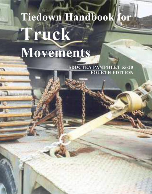
Tiedown Handbook for
Truck Movements
SDDCTEA PAMPHLET 55-20 FOURTH EDITION
SDDCTEA PAMPHLET 55-19
TIEDOWN HANDBOOK
FOR
TRUCK MOVEMENTS
FOURTH EDITION July 2008
(Electronically Revised May 2009)
Michael Bartosiak
Graphic designs: Terry L. Jenkins Pamphlet consultant: Robert E. Kerr
______________________________________________________ MILITARY SURFACE DEPLOYMENT AND DISTRIBUTION COMMAND
TRANSPORTATION ENGINEERING AGENCY SCOTT AIR FORCE BASE, ILLINOIS
FOURTH EDITION SDDCTEA PAMPHLET 55-20
ii
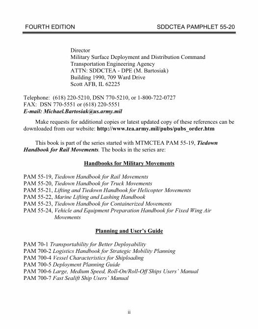
Director Military Surface Deployment and Distribution Command Transportation Engineering Agency ATTN: SDDCTEA - DPE (M. Bartosiak) Building 1990, 709 Ward Drive Scott AFB, IL 62225
Telephone: (618) 220-5210, DSN 770-5210, or 1-800-722-0727 FAX: DSN 770-5551 or (618) 220-5551 E-mail: [email protected]
Make requests for additional copies or latest updated copy of these references can be downloaded from our website: http://www.tea.army.mil/pubs/pubs_order.htm
This book is part of the series started with MTMCTEA PAM 55-19, Tiedown
Handbook for Rail Movements. The books in the series are:
Handbooks for Military Movements PAM 55-19, Tiedown Handbook for Rail Movements PAM 55-20, Tiedown Handbook for Truck Movements PAM 55-21, Lifting and Tiedown Handbook for Helicopter Movements PAM 55-22, Marine Lifting and Lashing Handbook PAM 55-23, Tiedown Handbook for Containerized Movements PAM 55-24, Vehicle and Equipment Preparation Handbook for Fixed Wing Air
Movements
Planning and User’s Guide
PAM 70-1 Transportability for Better Deployability PAM 700-2 Logistics Handbook for Strategic Mobility Planning PAM 700-4 Vessel Characteristics for Shiploading PAM 700-5 Deployment Planning Guide PAM 700-6 Large, Medium Speed, Roll-On/Roll-Off Ships Users’ Manual PAM 700-7 Fast Sealift Ship Users’ Manual
FOURTH EDITION SDDCTEA PAMPHLET 55-20
iii
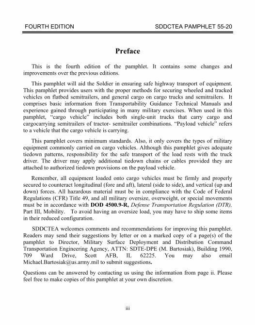
Preface
This is the fourth edition of the pamphlet. It contains some changes and improvements over the previous editions.
This pamphlet will aid the Soldier in ensuring safe highway transport of equipment. This pamphlet provides users with the proper methods for securing wheeled and tracked vehicles on flatbed semitrailers, and general cargo on cargo trucks and semitrailers. It comprises basic information from Transportability Guidance Technical Manuals and experience gained through participating in many military exercises. When used in this pamphlet, “cargo vehicle” includes both single-unit trucks that carry cargo and cargocarrying semitrailers of tractor- semitrailer combinations. “Payload vehicle” refers to a vehicle that the cargo vehicle is carrying.
This pamphlet covers minimum standards. Also, it only covers the types of military equipment commonly carried on cargo vehicles. Although this pamphlet gives adequate tiedown patterns, responsibility for the safe transport of the load rests with the truck driver. The driver may apply additional tiedown chains or cables provided they are attached to authorized tiedown provisions on the payload vehicle.
Remember, all equipment loaded onto cargo vehicles must be firmly and properly secured to counteract longitudinal (fore and aft), lateral (side to side), and vertical (up and down) forces. All hazardous material must be in compliance with the Code of Federal Regulations (CFR) Title 49, and all military oversize, overweight, or special movements must be in accordance with DOD 4500.9-R, Defense Transportation Regulation (DTR), Part III, Mobility. To avoid having an oversize load, you may have to ship some items in their reduced configuration.
SDDCTEA welcomes comments and recommendations for improving this pamphlet. Readers may send their suggestions by letter or on a marked copy of a page(s) of the pamphlet to Director, Military Surface Deployment and Distribution Command Transportation Engineering Agency, ATTN: SDTE-DPE (M. Bartosiak), Building 1990, 709 Ward Drive, Scott AFB, IL 62225. You may also email [email protected] to submit suggestions.
Questions can be answered by contacting us using the information from page ii. Please feel free to make copies of this pamphlet at your own discretion.

FOURTH EDITION SDDCTEA PAMPHLET 55-20
iv
Notes
FOURTH EDITION SDDCTEA PAMPHLET 55-20
v
TIEDOWN HANDBOOK FOR TRUCK MOVEMENTS
CONTENTS
Section Page I. GENERAL CARGO AND LOADING PRINCIPLES ......................................... 1
II. MILITARY CARGO VEHICLES ........................................................................ 9
A. General ......................................................................................................... 9
B. M172A1 Lowbed Semitrailer ....................................................................... 16
C. M870 and M870A1 Semitrailers ................................................................... 16
D. M872-Series (and M871) Flatbed Semitrailers ............................................. 36
E. M747 Semitrailer .......................................................................................... 45
F. M1000 Semitrailer ........................................................................................ 58
G. Trucks with Shelters ..................................................................................... 71
H. Palletized Load System (PLS) ...................................................................... 72
III. GENERAL FLATBED SEMITRAILER LOADS ............................................... 81
A. Tiedown with Chains .................................................................................... 81
B. Tiedown with Wire Rope .............................................................................. 89
C. Tiedown with Web Strap .............................................................................. 100
D. Tiedown with Steel banding ......................................................................... 104
FOURTH EDITION SDDCTEA PAMPHLET 55-20
vi
CONTENTS - cont Section Page
IV. PAYLOAD VEHICLE TIEDOWN TIPS ............................................................. 107
A. Preparing Payload Vehicles Prior to Loading ............................................... 107
B. Loading Payload Vehicles ............................................................................ 107
C. Securing Vehicles ......................................................................................... 109
D. Toolkit .......................................................................................................... 111
V. FORSCOM CARGO FORMS .............................................................................. 114
A. General ............................................................................................................ 114
B. FORSCOM Form 285-R ................................................................................. 114
C. DD Form 1750 ................................................................................................ 118
ACRONYMS ....................................................................................................... 121
FOURTH EDITION SDDCTEA PAMPHLET 55-20
vii
LIST OF ILLUSTRATIONS Figure Page 1 Common cargo loading “Do’s” and “Don’ts” ...................................................... 3
2 Five-ton truck on semitrailer illustrating chains and cables in crossed and same-side patterns ......................................................................... 11
3 Interference with a same-side pattern ................................................................... 12
4 Two chains using the same side tiedown fitting ................................................... 13
5 Crossed chains for inadequate chain length with same side pattern ...................... 14
6 Tiedowns with no lateral angle ............................................................................. 15
7 Detail of chain tiedown configuration using a loadbinder .................................... 17
8 M172A1 semitrailer .............................................................................................. 18
9 M113 or similar vehicle on the M172A1 .............................................................. 19
10 6K variable reach rough terrain forklift (VRRTFL) on the M172A1 ................... 20
11 M870 semitrailer ................................................................................................... 21
12 M870A1 semitrailer .............................................................................................. 22
13 Tiedown configuration of the M1097 HMMWV or similar vehicle on the M870 .......................................................................................................... 24
14 Detail on attaching chains to the M870 outrigger supports ................................... 25
15 Tiedown configuration of the M1028 CUCV or similar vehicle on the M870A1 ..................................................................................................... 36
16 Tiedown configuration of the M9 ACE on the M870 ........................................... 26
17 Tiedown configuration of grader on the M870 ..................................................... 27
18 Tiedown configuration of grader on the M870A1 ................................................ 28
19 Tiedown configuration of scoop loader on the M870 ........................................... 29
FOURTH EDITION SDDCTEA PAMPHLET 55-20
viii
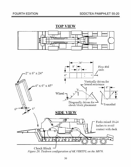
LIST OF ILLUSTRATIONS - cont Figure Page 20 Tiedown configuration of 6K VRRTFL on the M870 .......................................... 30
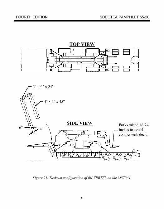
21 Tiedown configuration of 6K VRRTFL on the M870A1 ..................................... 31
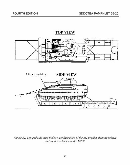
22 Top and side view tiedown configuration of the M2 Bradley fighting vehicle and similar vehicles on the M870 ......................................................................... 32
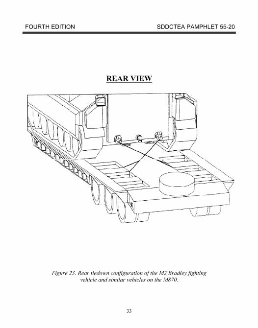
23 Rear tiedown configuration of the M2 Bradley fighting vehicle and similar vehicles on the M870 ............................................................................................ 33
24 Top and side view tiedown configuration of the M2 Bradley fighting vehicle and similar vehicles on the M870A1 .................................................................... 34
25 Rear view of the M2 Bradley fighting vehicle and similar vehicles on the M870A1 ..................................................................................................... 35
26 3D views of the M872A1, M872A2, and M872A3 semitrailers ........................... 37
27 Operation of the M872 retractable twist lock ....................................................... 38
28 Operation of the M872A3 retractable twist lock ................................................... 39
29 M872 removable container locks .......................................................................... 40
30 Installation of M872 side racks and removable side stakes .................................. 41
31 Two M113 variants secured to an M872A1 or M872A2 ...................................... 42
32 Two M113 variants secured to an M872A3 ........................................................... 43
33 HMMWVs on M872A1 or M872A2 .................................................................... 44
34 M747 HET ............................................................................................................. 46
35 M747 loading ramp tiedown ................................................................................. 47
36 Blocks under the M747 for loads over 55 tons ..................................................... 48
37 M747 curbing positions ........................................................................................ 50
38 M747 curbing ....................................................................................................... 51
FOURTH EDITION SDDCTEA PAMPHLET 55-20
ix
LIST OF ILLUSTRATIONS - cont Figure Page 39 M1 tank on the M747 ........................................................................................... 53
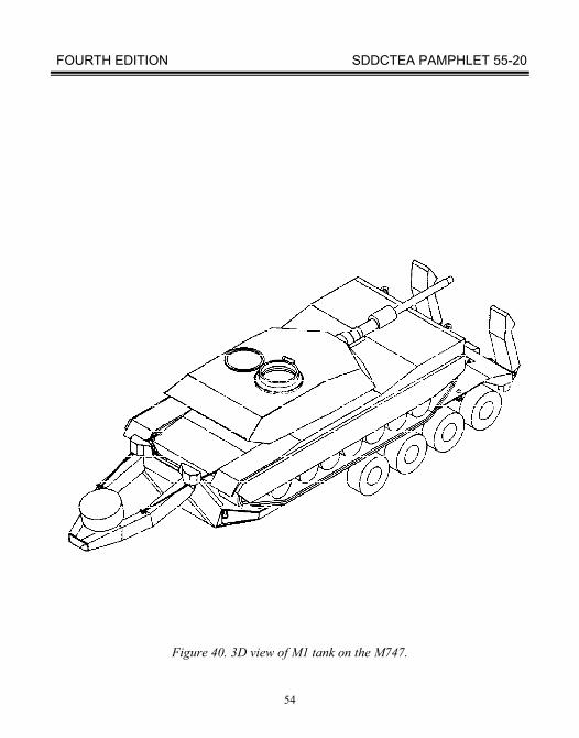
40 3D view of M1 tank on the M747 ......................................................................... 54
41 M60-series tank on the M747 ............................................................................... 55
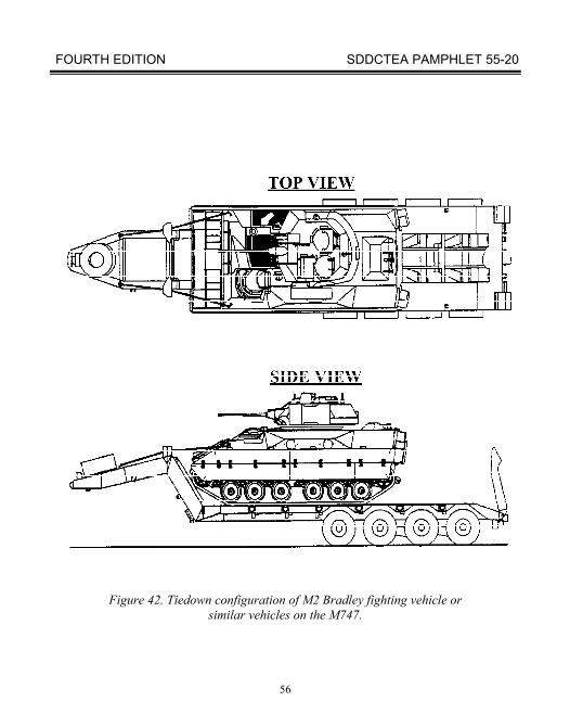
42 Tiedown configuration of M2 Bradley fighting vehicle or similar vehicles on the M747 ............................................................................................ 56
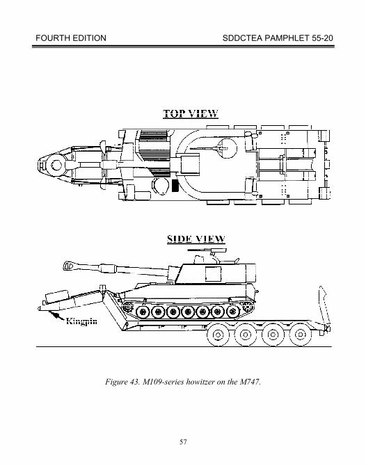
43 M109-series howitzer on the M747 ...................................................................... 57
44 M1000 HET ........................................................................................................... 59
45 M2 Bradley fighting vehicle on the M1000 .......................................................... 60
46 M2 Bradley fighting vehicle facing forward on the M1000 (rear view) ............... 61
47 M109-series howitzer on the M1000 .................................................................... 63
48 Front angled view of M1 tank on the M1000 ....................................................... 64
49 M1 tank on the M1000 ......................................................................................... 65
50 Rear view of M1 tank on the M1000 .................................................................... 66
51 M60-series tank on the M1000 ............................................................................. 67
52 Tiedown configuration of M113 and similar vehicles on the M1000 ................... 69
53 Shoring for M104 Wolverine Bridge and Wolverine loaded on M1000 ............... 70
54 Securing the S-280 shelters to trucks .................................................................... 71
55 Palletized load system truck with material handling crane ................................... 72
56 Palletized load system trailer ................................................................................ 72
57 M1077 flatrack ..................................................................................................... 73
58 M1 flatrack ........................................................................................................... 74
59a M3 and M3A1 ...................................................................................................... 75
FOURTH EDITION SDDCTEA PAMPHLET 55-20
x
LIST OF ILLUSTRATIONS - cont Figure Page 60 Palletized load system M1077 flatrack ................................................................. 77
61 HMMWV on a PLS flatrack ................................................................................. 79
62 Payload on an M1077 A-frame flatrack ................................................................ 80
63 Tie-down for M119A2 on semitrailer .................................................................... 82
64 Types of loadbinders ............................................................................................. 84
65 Tying down using chain ........................................................................................ 87
66 Chain tiedown running through a stake pocket ..................................................... 90
67 Tying down using wire rope ................................................................................. 92
68 Complete loop wire rope assembly ....................................................................... 96
69 Single strand wire rope assembly ......................................................................... 97
70 Detail of thimble attachment ................................................................................. 98
71 Turnbuckles .......................................................................................................... 99
72 Chain hoist and cable grippers .............................................................................. 101
73 Chain hoist and cable grippers in use .................................................................... 101
74 Web strap (NSN 5340-01-204-3009) .................................................................... 103
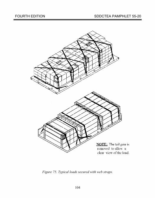
75 Typical loads secured with web straps .................................................................. 104
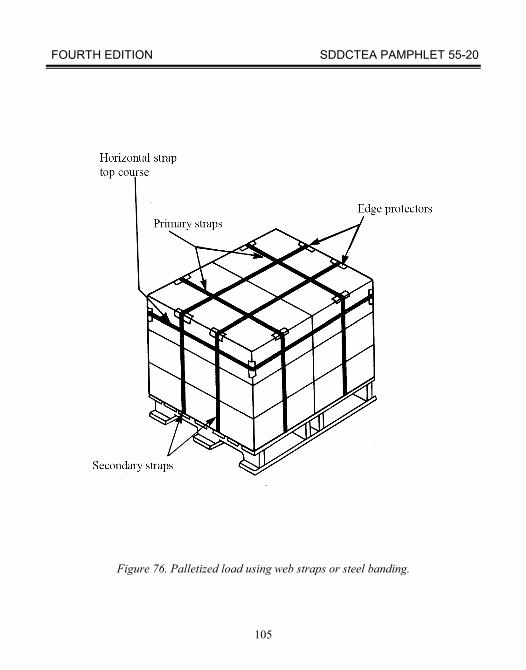
76 Palletized load using web straps or steel banding ................................................. 105
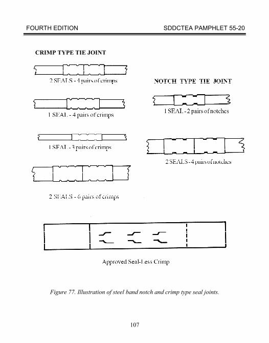
77 Illustration of steel band notch and crimp type seal joints .................................... 107
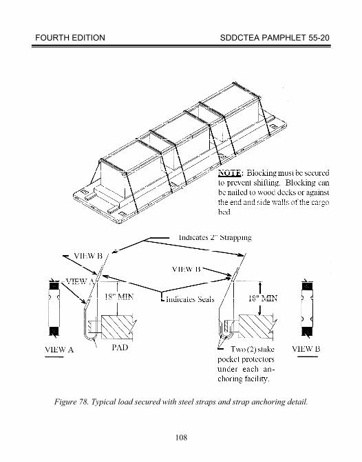
78 Typical load secured with steel straps and strap anchoring detail ......................... 108
79 When to use dunnage ............................................................................................ 112
80 FORSCOM Form 285-R (sample vehicle loading card) ....................................... 117
81 DD Form 1750 (sample vehicle packing list) ....................................................... 121
FOURTH EDITION SDDCTEA PAMPHLET 55-20
xi
LIST OF TABLES
Table Page 1 Military Semitrailers .............................................................................................. 10
2 Positions for M747 Curbing ................................................................................. 49
3 Loadbinders .......................................................................................................... 83
4 Common Chains ................................................................................................... 84
5 Wire Rope .............................................................................................................. 93
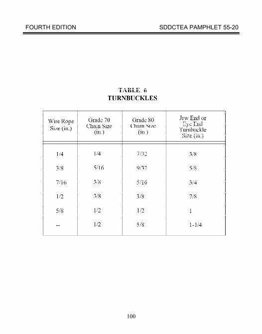
6 Turnbuckles .......................................................................................................... 98
7 Suggested Vehicle Loading Toolkit ....................................................................... 112
FOURTH EDITION SDDCTEA PAMPHLET 55-20
1
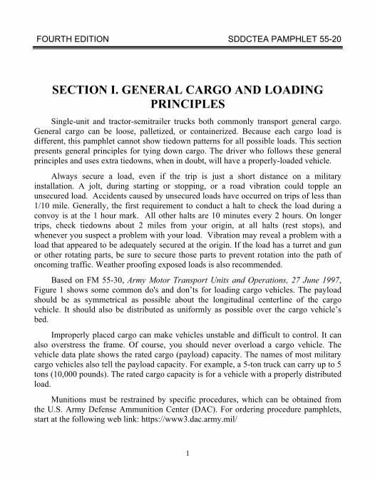
SECTION I. GENERAL CARGO AND LOADING
PRINCIPLES Single-unit and tractor-semitrailer trucks both commonly transport general cargo.
General cargo can be loose, palletized, or containerized. Because each cargo load is different, this pamphlet cannot show tiedown patterns for all possible loads. This section presents general principles for tying down cargo. The driver who follows these general principles and uses extra tiedowns, when in doubt, will have a properly-loaded vehicle.
Always secure a load, even if the trip is just a short distance on a military installation. A jolt, during starting or stopping, or a road vibration could topple an unsecured load. Accidents caused by unsecured loads have occurred on trips of less than 1/10 mile. Generally, the first requirement to conduct a halt to check the load during a convoy is at the 1 hour mark. All other halts are 10 minutes every 2 hours. On longer trips, check tiedowns about 2 miles from your origin, at all halts (rest stops), and whenever you suspect a problem with your load. Vibration may reveal a problem with a load that appeared to be adequately secured at the origin. If the load has a turret and gun or other rotating parts, be sure to secure those parts to prevent rotation into the path of oncoming traffic. Weather proofing exposed loads is also recommended.
Based on FM 55-30, Army Motor Transport Units and Operations, 27 June 1997, Figure 1 shows some common do's and don’ts for loading cargo vehicles. The payload should be as symmetrical as possible about the longitudinal centerline of the cargo vehicle. It should also be distributed as uniformly as possible over the cargo vehicle’s bed.
Improperly placed cargo can make vehicles unstable and difficult to control. It can also overstress the frame. Of course, you should never overload a cargo vehicle. The vehicle data plate shows the rated cargo (payload) capacity. The names of most military cargo vehicles also tell the payload capacity. For example, a 5-ton truck can carry up to 5 tons (10,000 pounds). The rated cargo capacity is for a vehicle with a properly distributed load.
Munitions must be restrained by specific procedures, which can be obtained from the U.S. Army Defense Ammunition Center (DAC). For ordering procedure pamphlets, start at the following web link: https://www3.dac.army.mil/
FOURTH EDITION SDDCTEA PAMPHLET 55-20
2
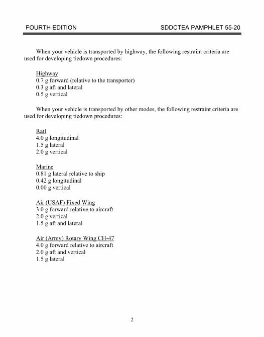
When your vehicle is transported by highway, the following restraint criteria are used for developing tiedown procedures:
Highway 0.7 g forward (relative to the transporter) 0.3 g aft and lateral 0.5 g vertical
When your vehicle is transported by other modes, the following restraint criteria are used for developing tiedown procedures:
Rail 4.0 g longitudinal 1.5 g lateral 2.0 g vertical
Marine 0.81 g lateral relative to ship 0.42 g longitudinal 0.00 g vertical
Air (USAF) Fixed Wing 3.0 g forward relative to aircraft 2.0 g vertical 1.5 g aft and lateral
Air (Army) Rotary Wing CH-47 4.0 g forward relative to aircraft 2.0 g aft and vertical 1.5 g lateral
FOURTH EDITION SDDCTEA PAMPHLET 55-20
3
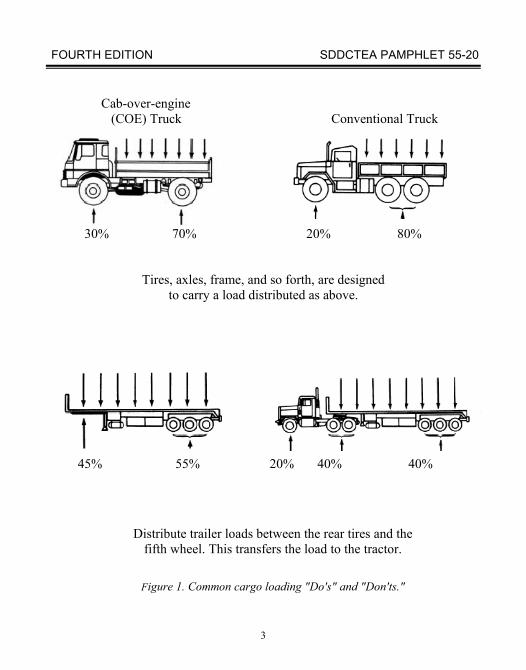
Cab-over-engine (COE) Truck Conventional Truck
30% 70% 20% 80%
Tires, axles, frame, and so forth, are designed to carry a load distributed as above.
45% 55% 20% 40% 40%
Distribute trailer loads between the rear tires and the fifth wheel. This transfers the load to the tractor.
Figure 1. Common cargo loading "Do's" and "Don'ts."
FOURTH EDITION SDDCTEA PAMPHLET 55-20
4
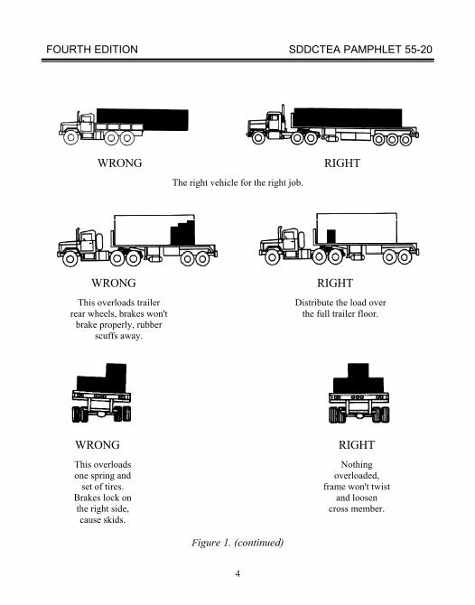
WRONG RIGHT
The right vehicle for the right job.
WRONG RIGHT This overloads trailer Distribute the load over rear wheels, brakes won't the full trailer floor. brake properly, rubber scuffs away.
WRONG RIGHT This overloads Nothing one spring and overloaded, set of tires. frame won't twist Brakes lock on and loosen the right side, cross member. cause skids.
Figure 1. (continued)
FOURTH EDITION SDDCTEA PAMPHLET 55-20
5
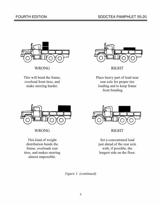
WRONG RIGHT
This will bend the frame, Place heavy part of load near overload front tires, and rear axle for proper tire make steering harder. loading and to keep frame from bending.
WRONG RIGHT
This kind of weight Set a concentrated load distribution bends the just ahead of the rear axle frame, overloads rear with, if possible, the tires, and makes steering longest side on the floor. almost impossible.
Figure 1. (continued)
FOURTH EDITION SDDCTEA PAMPHLET 55-20
6
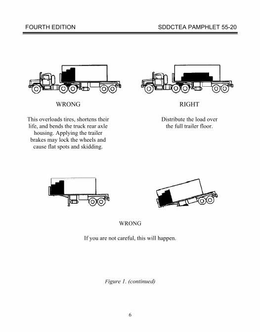
WRONG RIGHT
This overloads tires, shortens their Distribute the load over life, and bends the truck rear axle the full trailer floor. housing. Applying the trailer brakes may lock the wheels and cause flat spots and skidding.
WRONG
If you are not careful, this will happen.
Figure 1. (continued)
FOURTH EDITION SDDCTEA PAMPHLET 55-20
7
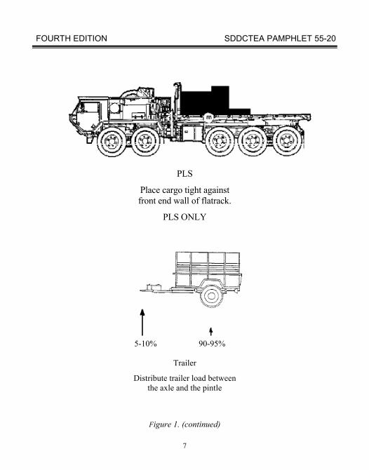
PLS
Place cargo tight against front end wall of flatrack.
PLS ONLY
5-10% 90-95%
Trailer
Distribute trailer load between the axle and the pintle
Figure 1. (continued)
FOURTH EDITION SDDCTEA PAMPHLET 55-20
8
A cargo vehicle with substantial side and end boards (or stakes) may not need
tiedowns if the cargo:
(a) can be loaded against the sides and forward end without voids,
(b)the cargo is below the top of the side and end boards, and
(c) there is no danger of the cargo tipping over or shifting dangerously.
Cargo in sacks will usually be stable if personnel stagger the layers of sacks. Most loads will need securement to prevent shifting and damage. You must secure all loads on flatbeds without sides to keep the loads from falling off. All cargo on the PLS flatrack must be tied down to prevent shifting.
Chains and loadbinders are usually the best devices for securing large items on cargo vehicles. You can use nylon or polyester straps (NSN 1670-00-725-1437 or NSN 5340-01-204-3009) to secure boxed or crated items weighing up to about 3,000 pounds. You can tie down heavier crates by using several nylon or polyester straps. Shippers can also use manila rope, wire rope, cargo nets, or steel banding to secure loads. Steel banding must be at least 5/8 and preferably 1-1/4 inches wide and must have at least two pairs of crimps in each seal and, when end-over-end lap joints are formed, must be sealed with at least two seals. When used during rail transport, steel banding must be approved by the Association of American Railroads.
These tiedown guidelines are valid for highway/cross-country transport. If the cargo vehicle will hold cargo while carried in an aircraft or on a railcar, then its cargo will need to be tied down more securely. It will have to meet the approval of the aircraft loadmaster or railroad representative, as appropriate. In general, items on vehicles riding on railcars must be fastened to the vehicle as securely as they would be fastened to a flatcar if they were riding directly on the flatcar. For guidance on securing items for rail transport, see TEA PAM 55-19, Tiedown Handbook for Rail Movements. Distribute the load over the full trailer floor.
If a cargo vehicle is aboard a ship, its cargo will usually be adequately restrained if it was properly restrained for movement over the highway. However, the vessel’s master is the final authority. In some cases, additional lateral restraint may be necessary. For guidance on securing items for marine transport, see TEA PAM 55-22, Lifting and Lashing Handbook for Marine Movements.
FOURTH EDITION SDDCTEA PAMPHLET 55-20
9
SECTION II. MILITARY CARGO VEHICLES
A. GENERAL
A commercial truck driver is responsible for securing exposed loads. Therefore, military personnel will rarely secure loads on commercial flatbeds. Even when military personnel load and help tie down cargo, the commercial truck driver is still responsible for ensuring that the tiedown arrangement is safe.
The driver of a military cargo vehicle is responsible for the safety of the load. The unit is responsible for loading and unloading the vehicle. Securing the cargo is a shared responsibility between the two. The truck driver will advise in securing the load and check to ensure it is safe for movement.
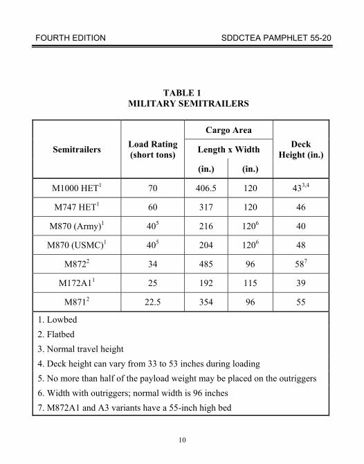
Table 1 summarizes common military flatbed semitrailers. The following paragraphs contain detailed information on some of these semitrailers. If several different types of cargo vehicles are available, the user must select one with an adequate load rating and cargo bed area. The lowest and lightest acceptable cargo vehicle will usually cause the fewest conflicts with highway weight and vertical clearance limits.
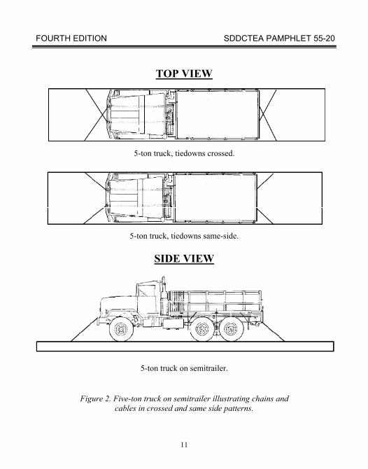
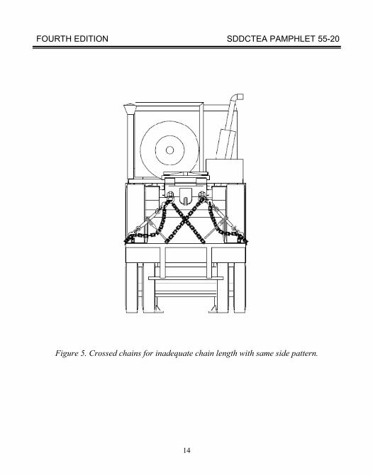
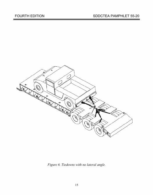
You should usually run chains or cables in a same-side pattern (fig 2). You should cross chains or cables when:
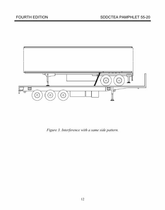
1. There is interference with a same-side pattern (fig 3).
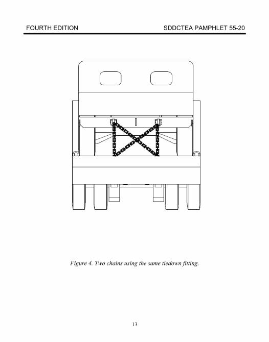
2. Two chains use the same tiedown fitting on the payload vehicle. In this case, one chain may be same-side and the other may be crossed (fig 4).
3. When the same-side pattern results in a chain length that is too short for the appropriate loadbinder (fig 5).
4. Same-side may not provide adequate lateral restraint, if the tiedowns have no lateral angle. In the end view, the two tiedowns would appear nearly parallel to each other and/or vertical if they have no lateral angle. In this case, a cross pattern should be used to secure the payload vehicle (fig 6).
FOURTH EDITION SDDCTEA PAMPHLET 55-20
10
TABLE 1 MILITARY SEMITRAILERS
Semitrailers Load Rating (short tons)
Cargo Area Deck
Height (in.) Length x Width
(in.) (in.)
M1000 HET1 70 406.5 120 433,4
M747 HET1 60 317 120 46
M870 (Army)1 405 216 1206 40
M870 (USMC)1 405 204 1206 48
M8722 34 485 96 587
M172A11 25 192 115 39
M8712 22.5 354 96 55
1. Lowbed 2. Flatbed 3. Normal travel height 4. Deck height can vary from 33 to 53 inches during loading 5. No more than half of the payload weight may be placed on the outriggers 6. Width with outriggers; normal width is 96 inches 7. M872A1 and A3 variants have a 55-inch high bed
FOURTH EDITION SDDCTEA PAMPHLET 55-20
11
TOP VIEW
5-ton truck, tiedowns crossed.
5-ton truck, tiedowns same-side.
SIDE VIEW
5-ton truck on semitrailer.
Figure 2. Five-ton truck on semitrailer illustrating chains and cables in crossed and same side patterns.
FOURTH EDITION SDDCTEA PAMPHLET 55-20
12
Figure 3. Interference with a same side pattern.
FOURTH EDITION SDDCTEA PAMPHLET 55-20
13
Figure 4. Two chains using the same tiedown fitting.
FOURTH EDITION SDDCTEA PAMPHLET 55-20
14
Figure 5. Crossed chains for inadequate chain length with same side pattern.
FOURTH EDITION SDDCTEA PAMPHLET 55-20
15
Figure 6. Tiedowns with no lateral angle.
FOURTH EDITION SDDCTEA PAMPHLET 55-20
16
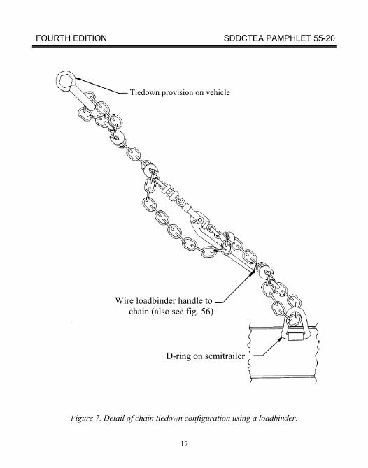
Many military flatbeds have basic issue item (BII) chains and loadbinders. Use chains and loadbinders when they are available. Figure 7 shows a typical chain and loadbinder combination.
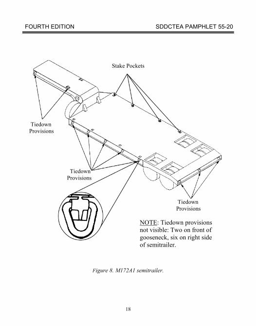
B. M172A1 LOWBED SEMITRAILER
The M172A1 (fig 8) is a common military lowbed semitrailer with a 25-ton capacity. These trailers have portable ramps for use at the rear end. Their bed width is 115 inches. The M172A1 has 19 lashing rings (D-rings); 5 on each side, 3 on the rear, and 6 on the gooseneck. These semitrailers have open wheel wells and a usable bed length of 192 inches.
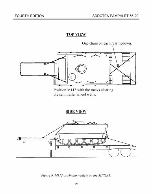
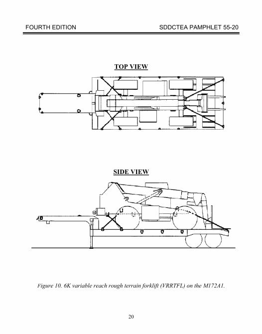
A load on an M172A1 gets adequate forward restraint if it is firmly against the gooseneck. You must use chains or cables to provide adequate vertical, lateral, and rearward restraint. Some loads cannot rest against the gooseneck. If the semitrailer is carrying an item that is not touching the gooseneck, chains must restrain it against forward motion as well. Figures 9 and 10 show adequately restrained loads on this semitrailer. Restraint patterns in figures 9 and 10 use 3/8-inch chain assemblies (NSN 4010-00-803-8858) and loadbinders (NSN 3990-01-213-1746).
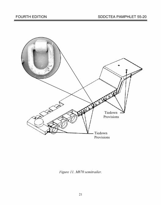
C. M870 AND M870A1 SEMITRAILERS
The M870 and M870A1 are adaptions of commercial construction equipment haulers. They can haul most types of military construction equipment and most tracked vehicles that weigh less than 40 tons. Blocking and bracing generally are not required. Figures 11 and 12 show the M870 and M870A1. You can load these trailers at end ramps or by uncoupling from the tractor and dropping the gooseneck to use as a front ramp. The USMC version of the M870 also has portable ramps for use at its back end. These semitrailers have a normal bed width of 96 inches. However, outriggers can extend the bed width to 120 inches. Loads wider than 96 inches must be loaded over the back end since the outriggers do not extend over the gooseneck portion. At least 1/2 of the tire or track must be placed on the 96" bed width. The remainder may be placed on the outrigger. An the exception is all versions of the hydraulic excavator (HYEX) which has been approved for the M870 and M870A1.
FOURTH EDITION SDDCTEA PAMPHLET 55-20
17
Tiedown provision on vehicle
Wire loadbinder handle to chain (also see fig. 56) D-ring on semitrailer
Figure 7. Detail of chain tiedown configuration using a loadbinder.
FOURTH EDITION SDDCTEA PAMPHLET 55-20
18
Stake Pockets
Tiedown Provisions Tiedown Provisions
Tiedown Provisions NOTE: Tiedown provisions not visible: Two on front of gooseneck, six on right side of semitrailer.
Figure 8. M172A1 semitrailer.
FOURTH EDITION SDDCTEA PAMPHLET 55-20
19
TOP VIEW
One chain on each rear tiedown.
Position M113 with the tracks clearing the semitrailer wheel wells.
SIDE VIEW
Figure 9. M113 or similar vehicle on the M172A1.
FOURTH EDITION SDDCTEA PAMPHLET 55-20
20
TOP VIEW
SIDE VIEW
Figure 10. 6K variable reach rough terrain forklift (VRRTFL) on the M172A1.
FOURTH EDITION SDDCTEA PAMPHLET 55-20
21
Tiedown Provisions
Tiedown Provisions
Figure 11. M870 semitrailer.
FOURTH EDITION SDDCTEA PAMPHLET 55-20
22
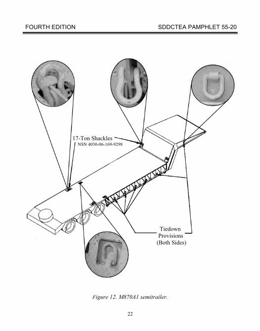
17-Ton Shackles NSN 4030-06-169-9298 Tiedown Provisions (Both Sides)
Figure 12. M870A1 semitrailer.
FOURTH EDITION SDDCTEA PAMPHLET 55-20
23
The M870 has six lashing rings (D-rings) on each side. It also has two D-rings on the rear cargo bed and four D-rings on the gooseneck. The M870A1 has five D-rings on each side. It also has two D-rings and two 17-ton shackles on the cargo bed and two D-rings and two 17-ton shackles on the gooseneck.
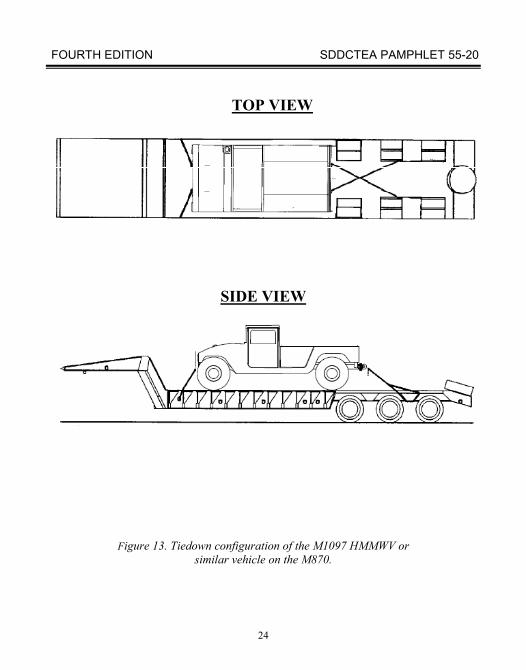
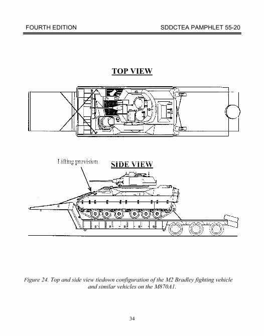
Figures 13 through 25 show adequately restrained loads on these semitrailers. Most vehicles will be easier to secure if they are snug against the M870 gooseneck. You can secure many vehicles by chaining the front payload vehicle lifting eye to D-rings on the M870 gooseneck (figs 16, 17, 22, and 24). A load on an M870 or M870A1 gets adequate forward restraint when parked firmly against the gooseneck. You must use chains or cables to provide adequate vertical, lateral, and rearward restraint. If the semitrailer is carrying two pieces of equipment, chains must restrain the item that is away from the gooseneck against forward motion as well. Many loads are too wide to restrain using the shackles on the M870A1 gooseneck. Bulldozer blades hide these shackles, for instance. Items that mask the shackles at the base of the gooseneck can be secured to D-rings on the top part of the gooseneck.
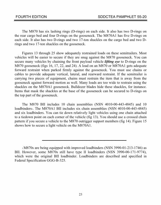
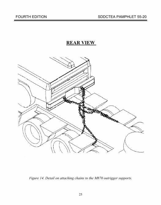
The M870 BII includes 10 chain assemblies (NSN 4010-00-443-4845) and 10 loadbinders1. The M870A1 BII includes six chain assemblies (NSN 4010-00-443-4845) and six loadbinders. You can tie down relatively light vehicles using one chain attached to a tiedown point on each corner of the vehicle (fig 13). You should use a crossed chain pattern if you secure a vehicle to the M870 outrigger support members (fig 14). Figure 15 shows how to secure a light vehicle on the M870A1.
_______________________ 1 M870s are being equipped with improved loadbinders (NSN 3990-01-213-1746) as
BII. However, some M870s still have type II loadbinders (NSN 3990-00-171-9774), which were the original BII loadbinder. Loadbinders are described and specified in Federal Specification GGG-B-325.
FOURTH EDITION SDDCTEA PAMPHLET 55-20
24
TOP VIEW
SIDE VIEW
Figure 13. Tiedown configuration of the M1097 HMMWV or similar vehicle on the M870.
FOURTH EDITION SDDCTEA PAMPHLET 55-20
25
REAR VIEW
Figure 14. Detail on attaching chains to the M870 outrigger supports.
FOURTH EDITION SDDCTEA PAMPHLET 55-20
26
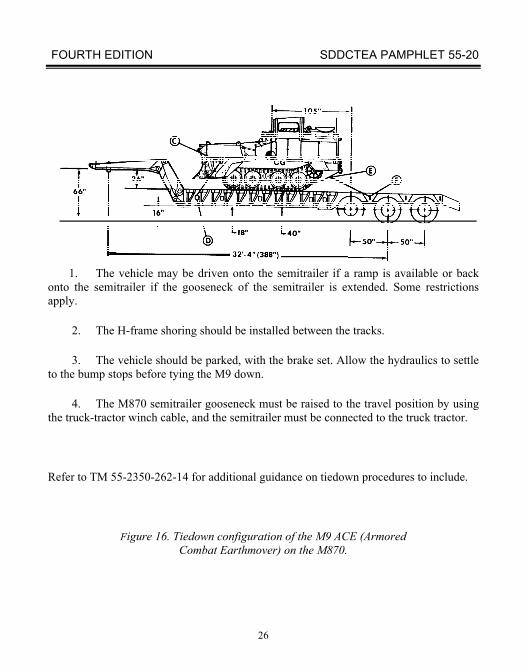
1. The vehicle may be driven onto the semitrailer if a ramp is available or back onto the semitrailer if the gooseneck of the semitrailer is extended. Some restrictions apply.
2. The H-frame shoring should be installed between the tracks.
3. The vehicle should be parked, with the brake set. Allow the hydraulics to settle to the bump stops before tying the M9 down.
4. The M870 semitrailer gooseneck must be raised to the travel position by using the truck-tractor winch cable, and the semitrailer must be connected to the truck tractor.
Refer to TM 55-2350-262-14 for additional guidance on tiedown procedures to include.
Figure 16. Tiedown configuration of the M9 ACE (Armored Combat Earthmover) on the M870.
FOURTH EDITION SDDCTEA PAMPHLET 55-20
27
TOP VIEW
SIDE VIEW
Lifting Provision
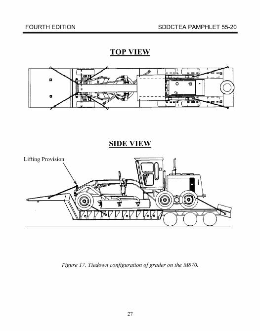
Figure 17. Tiedown configuration of grader on the M870.
FOURTH EDITION SDDCTEA PAMPHLET 55-20
28
TOP VIEW
SIDE VIEW
Lifting Provision
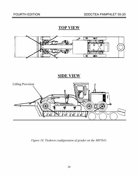
Figure 18. Tiedown configuration of grader on the M870A1.
FOURTH EDITION SDDCTEA PAMPHLET 55-20
29
REAR VIEW
2" x 6" x 24"
4" x 6" x 45"
6"
4" Dunnage straddles scoop loader pintle
SIDE VIEW
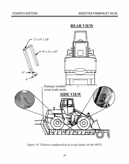
Figure 19. Tiedown configuration of scoop loader on the M870.
FOURTH EDITION SDDCTEA PAMPHLET 55-20
30
TOP VIEW
Figure 20. Tiedown configuration of 6K VRRTFL on the M870.
FOURTH EDITION SDDCTEA PAMPHLET 55-20
31
TOP VIEW
Figure 21. Tiedown configuration of 6K VRRTFL on the M870A1.
FOURTH EDITION SDDCTEA PAMPHLET 55-20
32
TOP VIEW
Figure 22. Top and side view tiedown configuration of the M2 Bradley fighting vehicle and similar vehicles on the M870.
FOURTH EDITION SDDCTEA PAMPHLET 55-20
33
REAR VIEW
Figure 23. Rear tiedown configuration of the M2 Bradley fighting vehicle and similar vehicles on the M870.
FOURTH EDITION SDDCTEA PAMPHLET 55-20
34
TOP VIEW
Figure 24. Top and side view tiedown configuration of the M2 Bradley fighting vehicle and similar vehicles on the M870A1.
FOURTH EDITION SDDCTEA PAMPHLET 55-20
35
REAR VIEW
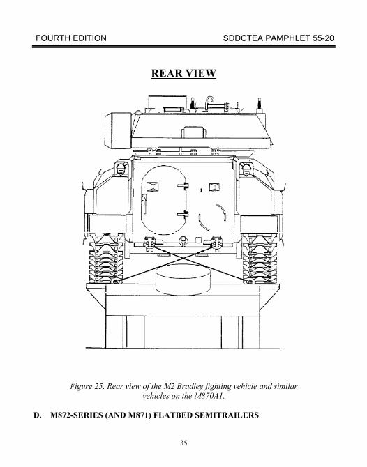
Figure 25. Rear view of the M2 Bradley fighting vehicle and similar vehicles on the M870A1.
D. M872-SERIES (AND M871) FLATBED SEMITRAILERS
FOURTH EDITION SDDCTEA PAMPHLET 55-20
36
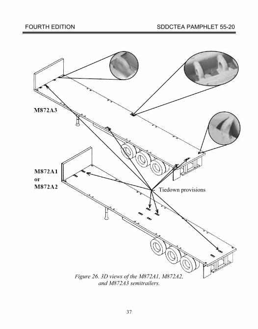
The M872-series 40-foot flatbed semitrailers can carry a wide variety of cargo. All models can carry containers, bulk cargo, and general cargo. The M872A1 (fig 26), A2, and A3 also have tiedown fittings for securing two M113s or similar vehicles. The M872 does not normally carry vehicles. These semitrailers are 96 inches wide and 490 inches long. The M872 and M872A2 deck height is 58 inches. The M872A1 and M872A3 deck height is 58inches. Units/shippers must arrange for container handling equipment (CHE), materials handling equipment (MHE), and/or loading ramps to load their cargo onto the M872-seriessemitrailers.
The operator's manual, TM 9-2330-359-14&P, shows how to use container locks and cargo rings on these semitrailers. Figures 27 through 30 are extracted from the operator's manual. Users should refer to the operator's manual for additional information on the M872.
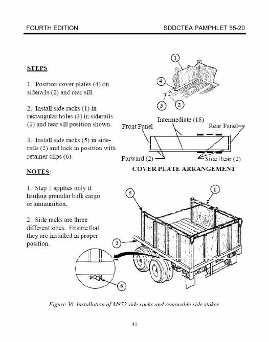
Figures 27 through 29 show how to use the container locks. You can secure one 40-foot container using the in-place retractable twist locks. You must also use removable container locks when securing two 20-foot containers or other containers shorter than 40 feet. You can use T-hooks to secure general cargo with straps. Figure 29 shows the installation of removable container locks. Figure 30 shows the M872 configured for carrying bulk cargo such as sand. You should use similar procedures when securing cargo to an M871 semitrailer.
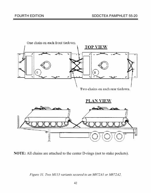
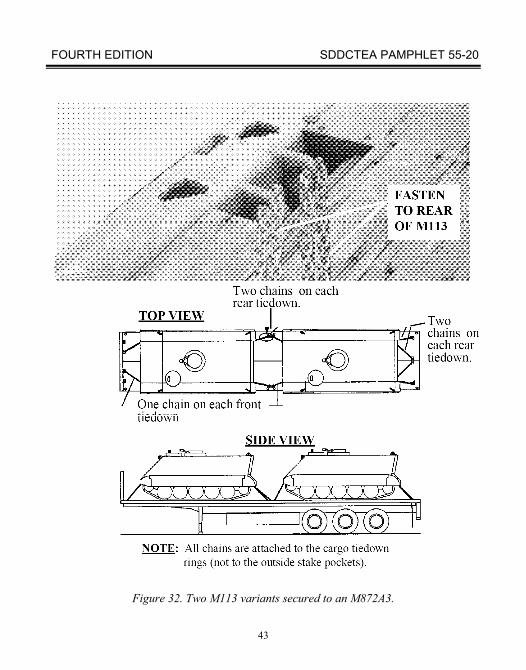
Figures 31 through 33 show vehicles loaded on an M872A1 or M872A2. The illustrated tiedown arrangements are based on using 1/2-inch chain assemblies (NSN 4010-00-803-8858) and loadbinders (NSN 3990-01-213-1746). You could also use these tiedown patterns if you use stronger chains.
FOURTH EDITION SDDCTEA PAMPHLET 55-20
37
Tiedown provisions
Figure 26. 3D views of the M872A1, M872A2, and M872A3 semitrailers.
FOURTH EDITION SDDCTEA PAMPHLET 55-20
38
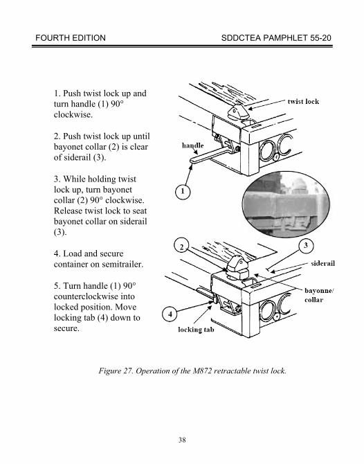
1. Push twist lock up and turn handle (1) 90° clockwise.
2. Push twist lock up until bayonet collar (2) is clear of siderail (3).
3. While holding twist lock up, turn bayonet collar (2) 90° clockwise. Release twist lock to seat bayonet collar on siderail (3).
4. Load and secure container on semitrailer.
5. Turn handle (1) 90° counterclockwise into locked position. Move locking tab (4) down to secure.
Figure 27. Operation of the M872 retractable twist lock.
FOURTH EDITION SDDCTEA PAMPHLET 55-20
39
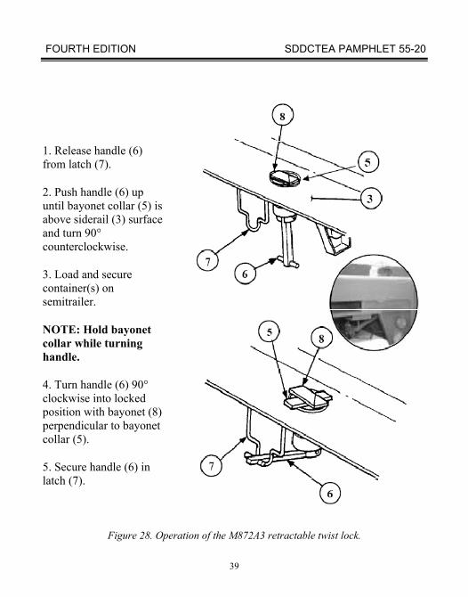
1. Release handle (6) from latch (7).
2. Push handle (6) up until bayonet collar (5) is above siderail (3) surface and turn 90° counterclockwise.
3. Load and secure container(s) on semitrailer.
NOTE: Hold bayonet collar while turning handle.
4. Turn handle (6) 90° clockwise into locked
position with bayonet (8)
perpendicular to bayonet
collar (5).
5. Secure handle (6) in latch (7).
Figure 28. Operation of the M872A3 retractable twist lock.
FOURTH EDITION SDDCTEA PAMPHLET 55-20
40
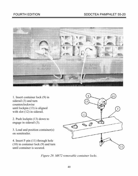
1. Insert container lock (9) in siderail (3) and turn counterclockwise until lockpin (13) is aligned with slot (12) in siderail. 2. Push lockpin (13) down to engage in siderail (3). 3. Load and position container(s) on semitrailer. 4. Insert F-pin (11) through hole (10) in container lock (9) and turn until container is secured.
Figure 29. M872 removable container locks.
FOURTH EDITION SDDCTEA PAMPHLET 55-20
41
Figure 30. Installation of M872 side racks and removable side stakes.
FOURTH EDITION SDDCTEA PAMPHLET 55-20
42
NOTE: All chains are attached to the center D-rings (not to stake pockets).
Figure 31. Two M113 variants secured to an M872A1 or M872A2.
FOURTH EDITION SDDCTEA PAMPHLET 55-20
43
Figure 32. Two M113 variants secured to an M872A3.
FOURTH EDITION SDDCTEA PAMPHLET 55-20
44
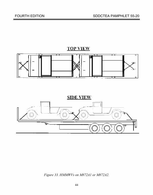
Figure 33. HMMWVs on M872A1 or M872A2.
FOURTH EDITION SDDCTEA PAMPHLET 55-20
45
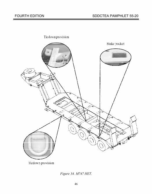
E. M747 SEMITRAILER
The M747 lowbed heavy equipment transporter (HET) (fig 34) has a rated load-carrying capacity of 60 tons. The overall length of the semitrailer is about 43 feet. The usable bed is 317 inches long, 44 inches above the ground, 120 inches wide, and can accept cargo with some side overhang. The M747 can carry heavy tracked vehicles, including the M1 tank.
The operator's manual, TM 9-2330-294-14, shows how to load both operable and inoperable vehicles. Users should refer to the operator's manual for additional information on the M747.
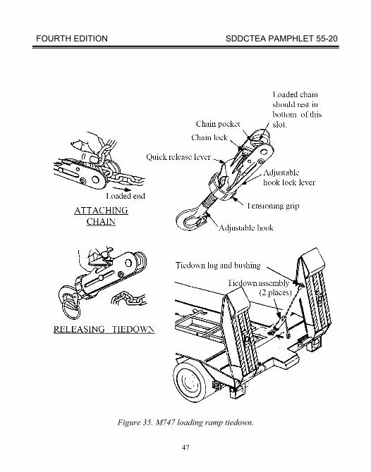
The M747 has two adjustable loading ramps at the rear of the semitrailer. Each ramp can be moved laterally to load different width vehicles. When the M747 travels, the ramps must be raised and secured in position by a chain tiedown assembly (fig 35). The ramps can be removed when loading the M747 from a permanent ramp or dock.
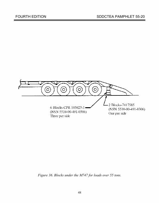
Two jacking pads are welded underneath the frame at the rear corners. The jacking pads are under the stenciled instructions, “BLOCK HERE.” You must put blocks under the jacking pads when loading a vehicle that weighs more than 55 tons. The M747 BII includes wood blocks for this purpose (fig 36).
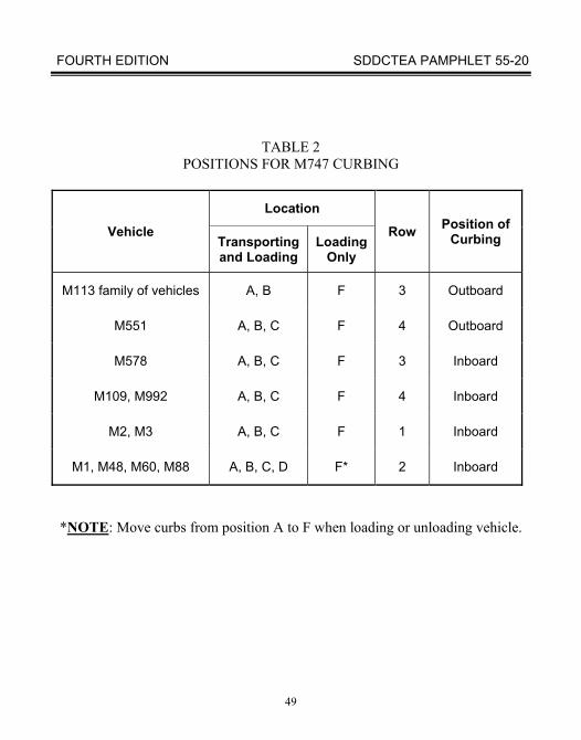
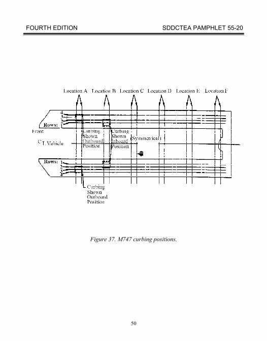
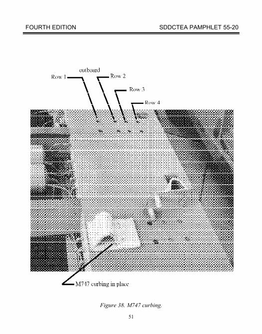
The M747 comes with eight removable curbs. Up to four curbs should be placed on each side of the M747. These curbs restrain cargo laterally during transport and help guide vehicles onto the M747 during loading operations. Table 2 and figures 37 and 38 show locations and proper positioning of the curbing. Six sets of holes on each side of the M747 bed are for placing the curbing. Each set of holes has four lateral positions for proper adjustment. The curb portion of the curbing assembly can be positioned either toward the center of the M747 (inboard) or toward the outer edge of the M747 (outboard). Curbing should always be in location “F” on each side of the M747 when loading or unloading vehicles. Location “A” curbing may be temporarily moved to location “F” for loading and unloading operations. Before moving the M747, stow location “F” curbs if not used in location "A."
FOURTH EDITION SDDCTEA PAMPHLET 55-20
46
Figure 34. M747 HET.
FOURTH EDITION SDDCTEA PAMPHLET 55-20
47
Figure 35. M747 loading ramp tiedown.
FOURTH EDITION SDDCTEA PAMPHLET 55-20
48
Figure 36. Blocks under the M747 for loads over 55 tons.
FOURTH EDITION SDDCTEA PAMPHLET 55-20
49
TABLE 2 POSITIONS FOR M747 CURBING
Vehicle
Location
Row Position of Curbing Transporting
and Loading Loading
Only
M113 family of vehicles A, B F 3 Outboard
M551 A, B, C F 4 Outboard
M578 A, B, C F 3 Inboard
M109, M992 A, B, C F 4 Inboard
M2, M3 A, B, C F 1 Inboard
M1, M48, M60, M88 A, B, C, D F* 2 Inboard
*NOTE: Move curbs from position A to F when loading or unloading vehicle.
FOURTH EDITION SDDCTEA PAMPHLET 55-20
50
Figure 37. M747 curbing positions.
FOURTH EDITION SDDCTEA PAMPHLET 55-20
51
Figure 38. M747 curbing.
FOURTH EDITION SDDCTEA PAMPHLET 55-20
52
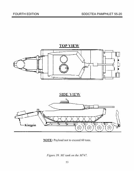
Load and park vehicles against the M747 gooseneck to prevent forward movement. The curbing provides much lateral restraint. However, chains are still necessary to prevent aft movement. The M747 comes with six BII 3/4-inch chains (NSN 4010-00-449-6573). These chains have a breaking strength of 50,400 pounds. The M747 also has six BII loadbinders (NSN 3990-00-401-1503). Figures 39 through 43 show tiedown patterns using these chains and loadbinders.
Vehicles in good condition can be driven onto the M747. Personnel can load disabled vehicles using a winch on the M911 truck tractor and the snatch block and roller assemblies on the trailer. Firm-tracked vehicles such as bulldozers should be attached to the winch cable, even if they are driven on. TM 9-2330-294-14 contains detailed instructions on using the winch, snatch block, and roller assemblies.
When possible, load on level ground. In adverse conditions, you can load on side and lateral slopes of up to 10 percent and with a towing vehicle - M747 offset angle up to 5°. Avoid loading on a severe downgrade to prevent the payload from rolling forward on the M747.
NOTE: If the vehicle is not placed in contact with the M747 gooseneck, tiedowns are required on both ends of the vehicle to prevent movement.
FOURTH EDITION SDDCTEA PAMPHLET 55-20
53
NOTE: Payload not to exceed 60 tons.
Figure 39. M1 tank on the M747.
FOURTH EDITION SDDCTEA PAMPHLET 55-20
54
Figure 40. 3D view of M1 tank on the M747.

FOURTH EDITION SDDCTEA PAMPHLET 55-20
55
Figure 41. M60-series tank on the M747.
FOURTH EDITION SDDCTEA PAMPHLET 55-20
56
Figure 42. Tiedown configuration of M2 Bradley fighting vehicle or
similar vehicles on the M747.
FOURTH EDITION SDDCTEA PAMPHLET 55-20
57
Figure 43. M109-series howitzer on the M747.
FOURTH EDITION SDDCTEA PAMPHLET 55-20
58
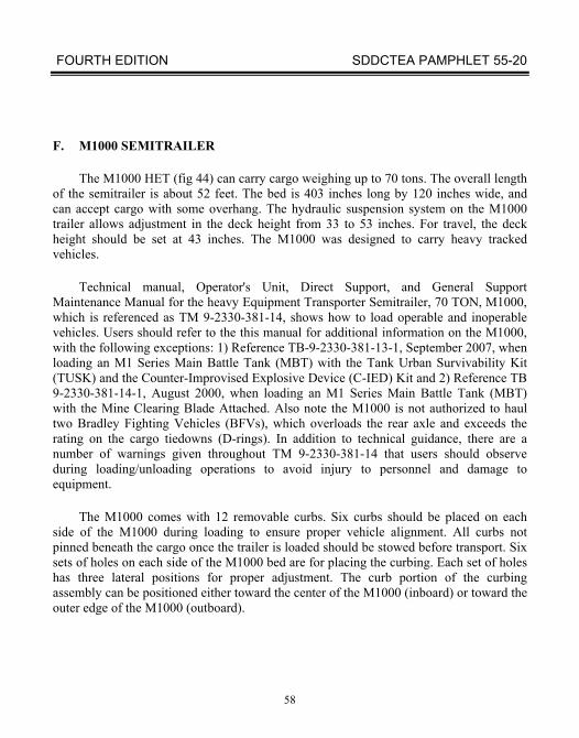
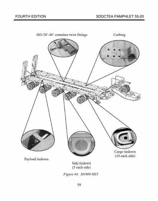
F. M1000 SEMITRAILER
The M1000 HET (fig 44) can carry cargo weighing up to 70 tons. The overall length of the semitrailer is about 52 feet. The bed is 403 inches long by 120 inches wide, and can accept cargo with some overhang. The hydraulic suspension system on the M1000 trailer allows adjustment in the deck height from 33 to 53 inches. For travel, the deck height should be set at 43 inches. The M1000 was designed to carry heavy tracked vehicles.
Technical manual, Operator's Unit, Direct Support, and General Support Maintenance Manual for the heavy Equipment Transporter Semitrailer, 70 TON, M1000, which is referenced as TM 9-2330-381-14, shows how to load operable and inoperable vehicles. Users should refer to the this manual for additional information on the M1000, with the following exceptions: 1) Reference TB-9-2330-381-13-1, September 2007, when loading an M1 Series Main Battle Tank (MBT) with the Tank Urban Survivability Kit (TUSK) and the Counter-Improvised Explosive Device (C-IED) Kit and 2) Reference TB 9-2330-381-14-1, August 2000, when loading an M1 Series Main Battle Tank (MBT) with the Mine Clearing Blade Attached. Also note the M1000 is not authorized to haul two Bradley Fighting Vehicles (BFVs), which overloads the rear axle and exceeds the rating on the cargo tiedowns (D-rings). In addition to technical guidance, there are a number of warnings given throughout TM 9-2330-381-14 that users should observe during loading/unloading operations to avoid injury to personnel and damage to equipment.
The M1000 comes with 12 removable curbs. Six curbs should be placed on each side of the M1000 during loading to ensure proper vehicle alignment. All curbs not pinned beneath the cargo once the trailer is loaded should be stowed before transport. Six sets of holes on each side of the M1000 bed are for placing the curbing. Each set of holes has three lateral positions for proper adjustment. The curb portion of the curbing assembly can be positioned either toward the center of the M1000 (inboard) or toward the outer edge of the M1000 (outboard).
FOURTH EDITION SDDCTEA PAMPHLET 55-20
58A
The curbing on the M1000 provides much lateral restraint. However, Chains are still necessary for longitudinal restraint. Basic Issue Items (BII) for the M1000 include, but are not limited to: six 1/2-inch alloy chains—
two - 7 feet long - NSN 4010-01-361-8378
two - 11 feet long - NSN 4010-01-371-5772
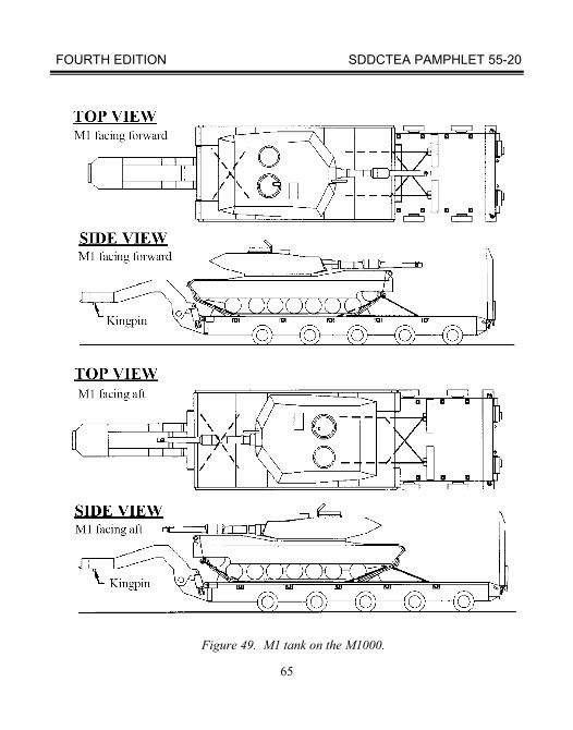
two - 19 feet long - NSN 4010-01-385-5974 six 1/2-inch load binders - NSN 3990-01-440-5975 (Two added for front chains) four 5/16-inch chain assemblies/utility chains, 11 ft long (for chock tie down) - NSN 4010-01-361-7267 two 5/16-inch load binders (for chock tie down) - NSN 3990-01-360-9669 Unlike the M747, it is not possible to place loads against the M1000 gooseneck, therefore, chains must provide forward restraint. You should use a four-chain and load binder same-side pattern when securing M2s and most other tracked vehicles weighing less than 75,000 pounds. You should position the payload vehicle so that the front chains form an angle of about 45o from the deck to the vehicle. The rear chain should be at an angle of about 30° to 45°. Figures 45 and 46 show restraint for an M2 or similar vehicle facing forward on the M1000.

FOURTH EDITION SDDCTEA PAMPHLET 55-20
58B
Notes
FOURTH EDITION SDDCTEA PAMPHLET 55-20
59
Figure 44. M1000 HET
ISO 20’-40’ container twist fittings Curbing
Side tiedown (5 each side)
Payload tiedown
Cargo tiedown (10 each side)
FOURTH EDITION SDDCTEA PAMPHLET 55-20
60
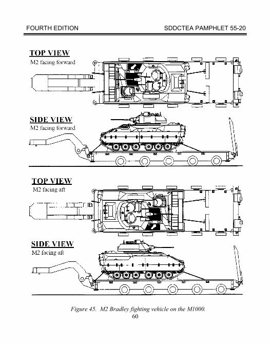
Figure 45. M2 Bradley fighting vehicle on the M1000.
FOURTH EDITION SDDCTEA PAMPHLET 55-20
61
REAR VIEW
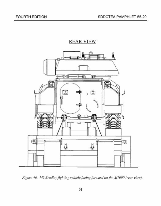
Figure 46. M2 Bradley fighting vehicle facing forward on the M1000 (rear view).
FOURTH EDITION SDDCTEA PAMPHLET 55-20
62
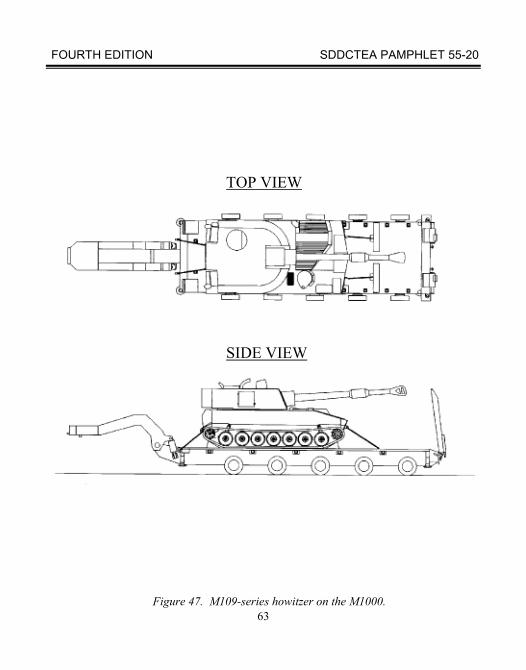
The M1000 can also carry most tracked vehicles facing aft. The tiedown pattern is similar to when the tracked vehicles face forward. Figure 45 shows an aft-facing M2 type vehicle. Figure 47 shows an M109.
The basic steps in loading and securing an M2 or other tracked vehicle that weighs less than 75,000 pounds are:
1. Properly position the side curbing.
2. Drive or winch the M2 to the proper position on the M1000. 3. Put the M1000 chock blocks in front of and behind the tracks. 4. Attach chains and tighten loadbinders.
Use the same basic steps in loading an M1 tank or other tracked vehicle over 75,000 pounds while using all six chains and load binders to secure the heavier load.
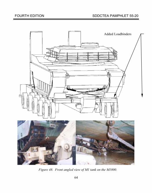
WARNING
Do not roll by gravity. Roll by winch or drive the vehicle into position for attaching chains and chain binders. Attach and tighten the six chains with load binders to avoid injury to personnel, damage to the vehicle, and over-stretching the chains. Figures 48 through 51 show procedures for securing heavy tracked vehicles to the M1000. For some figures, the trailer gooseneck is not shown, some inside axles are not shown on the M1000, and load binders are not shown in order to keep the drawings as legible as possible. Photographs instead show detail. Figures 48 through 51 show procedures for securing heavy tracked vehicles to the M1000.
FOURTH EDITION SDDCTEA PAMPHLET 55-20
63
Figure 47. M109-series howitzer on the M1000.
TOP VIEW
SIDE VIEW
FOURTH EDITION SDDCTEA PAMPHLET 55-20
64
Figure 48. Front angled view of M1 tank on the M1000.
Added Loadbinders
FOURTH EDITION SDDCTEA PAMPHLET 55-20
65
Figure 49. M1 tank on the M1000.
FOURTH EDITION SDDCTEA PAMPHLET 55-20
66
Figure 50. Rear view of M1 tank on M1000.
The image cannot be displayed. Your computer may not have enough memory to open the image, or the image may have been corrupted. Restart your computer, and then open the file again. If the red x still appears, you may have to delete the image and then insert it again.
FOURTH EDITION SDDCTEA PAMPHLET 55-20
67
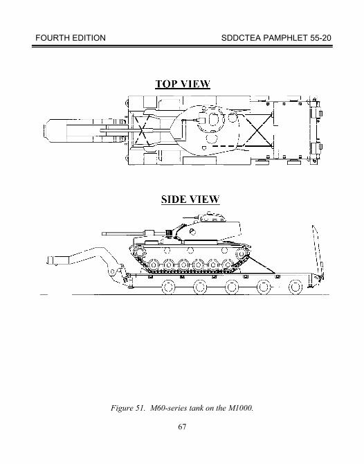
Figure 51. M60-series tank on the M1000.
FOURTH EDITION SDDCTEA PAMPHLET 55-20
68
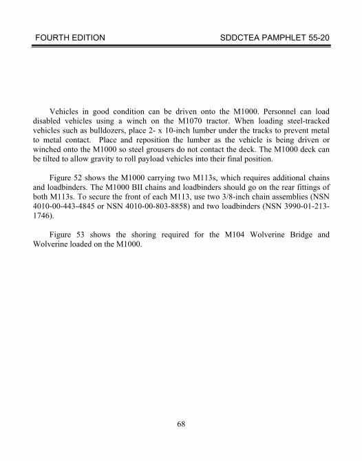
Vehicles in good condition can be driven onto the M1000. Personnel can load disabled vehicles using a winch on the M1070 tractor. When loading steel-tracked vehicles such as bulldozers, place 2- x 10-inch lumber under the tracks to prevent metal to metal contact. Place and reposition the lumber as the vehicle is being driven or winched onto the M1000 so steel grousers do not contact the deck. The M1000 deck can be tilted to allow gravity to roll payload vehicles into their final position.
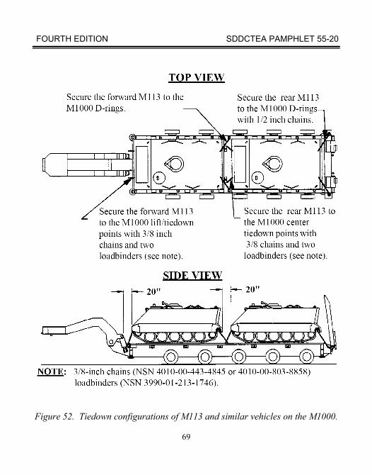
Figure 52 shows the M1000 carrying two M113s, which requires additional chains
and loadbinders. The M1000 BII chains and loadbinders should go on the rear fittings of both M113s. To secure the front of each M113, use two 3/8-inch chain assemblies (NSN 4010-00-443-4845 or NSN 4010-00-803-8858) and two loadbinders (NSN 3990-01-213-1746).
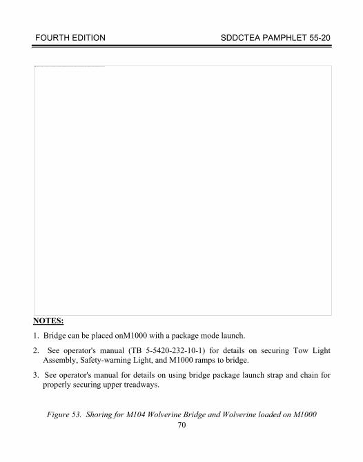
Figure 53 shows the shoring required for the M104 Wolverine Bridge and
Wolverine loaded on the M1000.
FOURTH EDITION SDDCTEA PAMPHLET 55-20
69
Figure 52. Tiedown configurations of M113 and similar vehicles on the M1000.
FOURTH EDITION SDDCTEA PAMPHLET 55-20
70
NOTES:
1. Bridge can be placed onM1000 with a package mode launch.
2. See operator's manual (TB 5-5420-232-10-1) for details on securing Tow Light Assembly, Safety-warning Light, and M1000 ramps to bridge.
3. See operator's manual for details on using bridge package launch strap and chain for properly securing upper treadways.
Figure 53. Shoring for M104 Wolverine Bridge and Wolverine loaded on M1000
The image cannot be displayed. Your computer may not have enough memory to open the image, or the image may have been corrupted. Restart your computer, and then open the file again. If the red x still appears, you may have to delete the image and then insert it again.
FOURTH EDITION SDDCTEA PAMPHLET 55-20
71
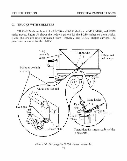
G. TRUCKS WITH SHELTERS
TB 43-0124 shows how to load S-280 and S-250 shelters on M35, M809, and M939 series trucks. Figure 54 shows the tiedown pattern for the S-280 shelter on these trucks. S-250 shelters are rarely unloaded from HMMWV and CUCV shelter carriers. The procedure is similar for the FMTV.
Figure 54. Securing the S-280 shelters to trucks.
FOURTH EDITION SDDCTEA PAMPHLET 55-20
72
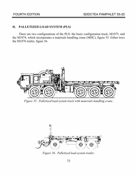
H. PALLETIZED LOAD SYSTEM (PLS)
There are two configurations of the PLS: the basic configuration truck, M1075, and the M1074, which incorporates a materials handling crane (MHC), figure 55. Either tows the M1076 trailer, figure 56.
Figure 55. Palletized load system truck with materials handling crane.
Figure 56. Palletized load system trailer.
FOURTH EDITION SDDCTEA PAMPHLET 55-20
73
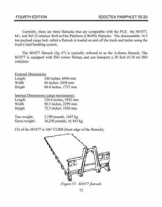
Currently, there are three flatracks that are compatible with the PLS: the M1077, M1, and M3 (Container Roll-in/Out Platform (CROP)) flatracks. The demountable 16.5 ton payload cargo bed, called a flatrack is loaded on and off the truck and trailer using the truck's load handling system.
The M1077 flatrack (fig 57) is typically referred to as the A-frame flatrack. The
M1077 is equipped with ISO corner fittings and can transport a 20 foot (6.10 m) ISO container.
External Dimensions: Length 240 inches, 6096 mm Width 96 inches, 2438 mm Height 68.4 inches, 1737 mm Internal Dimensions (cargo maximums): Length 230.4 inches, 5852 mm Width 90.5 inches, 2299 mm Height 72.3 inches, 1836 mm Tare weight: 3,190 pounds, 1447 kg Gross weight: 36,250 pounds, 16 443 kg CG of the M1077 is 106" CURB (front edge of the flatrack).
Figure 57. M1077 flatrack
FOURTH EDITION SDDCTEA PAMPHLET 55-20
74
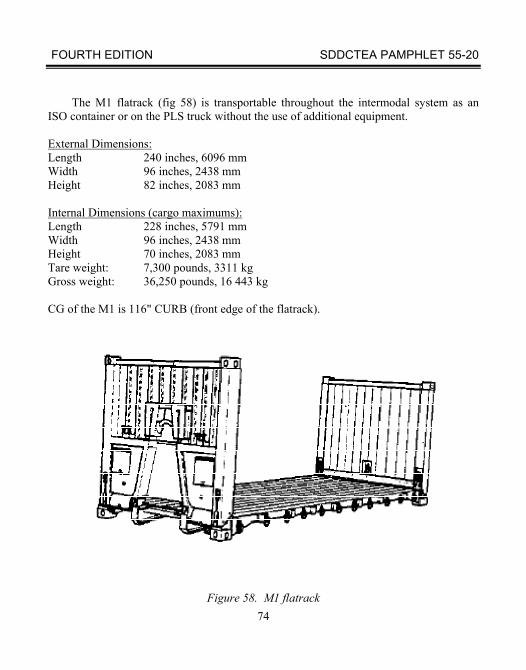
The M1 flatrack (fig 58) is transportable throughout the intermodal system as an ISO container or on the PLS truck without the use of additional equipment.
External Dimensions: Length 240 inches, 6096 mm Width 96 inches, 2438 mm Height 82 inches, 2083 mm Internal Dimensions (cargo maximums): Length 228 inches, 5791 mm Width 96 inches, 2438 mm Height 70 inches, 2083 mm Tare weight: 7,300 pounds, 3311 kg Gross weight: 36,250 pounds, 16 443 kg CG of the M1 is 116" CURB (front edge of the flatrack).
Figure 58. M1 flatrack
FOURTH EDITION SDDCTEA PAMPHLET 55-20
75
The image cannot be displayed. Your computer may not have enough memory to open the image, or the image may have been corrupted. Restart your computer, and then open the file again. If the red x still appears, you may have to delete the image and then insert it again.
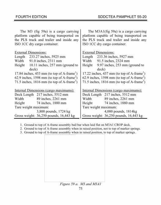
The M3 (fig 59a) is a cargo carrying platform capable of being transported on the PLS truck and trailer and inside any ISO 1CC dry cargo container.
External Dimensions: Length 233.27 inches, 5925 mm Width 91.0 inches, 2311 mm Height 10.11 inches, 257 mm (ground to
deck) 17.84 inches, 453 mm (to top of A-frame1) 62.9 inches, 1598 mm (to top of A-frame2) 71.5 inches, 1816 mm (to top of A-frame3) Internal Dimensions (cargo maximums): Deck Length 217 inches, 5512 mm Width 89 inches, 2261 mm Height 74 inches, 1880 mm Tare weight maximum: 3,800 pounds, 1724 kg Gross weight: 36,250 pounds, 16,443 kg
The M3A1(fig 59a) is a cargo carrying platform capable of being transported on the PLS truck and trailer and inside any ISO 1CC dry cargo container. External Dimensions: Length 233.36 inches, 5927 mm Width 91.5 inches, 2324 mm Height 9.97 inches, 253 mm (ground to
deck) 17.22 inches, 437 mm (to top of A-frame1) 62.9 inches, 1598 mm (to top of A-frame2) 71.5 inches, 1816 mm (to top of A-frame3) Internal Dimensions (cargo maximums): Deck Length 217 inches, 5512 mm Width 89 inches, 2261 mm Height 74 inches, 1880 mm Tare weight maximum: 4,000 pounds, 1814kg Gross weight: 36,250 pounds, 16,443 kg
1. Ground to top of A-frame assembly bail bar when laid flat on M3A1 CROP deck. 2. Ground to top of A-frame assembly when in raised position, not to top of marker springs. 3. Ground to top of A-frame assembly when in raised position, to top of marker springs.
Figure 59 a. M3 and M3A1
FOURTH EDITION SDDCTEA PAMPHLET 55-20
76
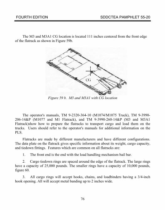
The M3 and M3A1 CG location is located 111 inches centered from the front edge
of the flatrack as shown in Figure 59b.
Figure 59 b. M3 and M3A1 with CG location
The operator's manuals, TM 9-2320-364-10 (M1074/M1075 Truck), TM 9-3990-206-14&P (M1077 and M1 Flatrack), and TM 9-3990-260-14&P (M3 and M3A1 Flatrack)show how to prepare the flatracks to transport cargo and load them on the trucks. Users should refer to the operator's manuals for additional information on the PLS.
Flatracks are made by different manufacturers and have different configurations. The data plate on the flatrack gives specific information about its weight, cargo capacity, and tiedown fittings. Features which are common on all flatracks are:
1. The front end is the end with the load handling mechanism bail bar.
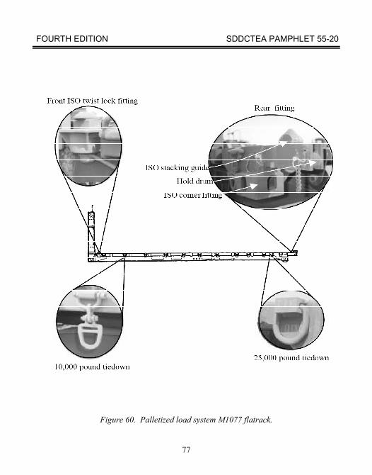
2. Cargo tiedown rings are spaced around the edge of the flatrack. The large rings have a capacity of 25,000 pounds. The smaller rings have a capacity of 10,000 pounds, figure 60.
3. All cargo rings will accept hooks, chains, and loadbinders having a 3/4-inch hook opening. All will accept metal banding up to 2 inches wide.
FOURTH EDITION SDDCTEA PAMPHLET 55-20
77
Figure 60. Palletized load system M1077 flatrack.
FOURTH EDITION SDDCTEA PAMPHLET 55-20
78
The M1077 flatrack has twist lock fittings (fig 60) so that a standard 20-foot ISO container can be locked in place without the use of chains. The containers will cause the truck to exceed the height for normal highway transport, requiring special permits and routing. The containers loaded on the M1076 trailer are within height limits for highway transport in the U.S.
The M1 flatrack is NATO intermodal, has a wood deck, and is the exact size of a
20-foot ISO container. Its end walls fold down on to the deck, and it has a maximum payload of 29,000 pounds.
The M3 and M3A1are NATO interoperable and were designed as a primary means
to ship strategic configured loads of ammunition from the depot to the user. These flatracks fit inside an ISO container and have a maximum payload capability of 32,250 pounds.
For adequate safety during highway operations with the tires inflated at highway tire
pressures, the following guidance should be followed when loading PLS flatracks. For operations with payloads of 12,000 pounds or less at speeds up to 55mph, the payload CG should be centered longitudinally and laterally on the flatrack and have a maximum height above the flatrack deck of 48" for the M1077, M3, and M3A1 or 39" for the M1. For operations with payloads of 12,000 pounds or less that exceed these CG heights, speeds should be restricted to a maximum of 50 mph. Light wheeled vehicles, such as the HMMWV (fig 61) and 4K forklifts, are approved for transport on the PLS as long as the specific vehicle's weight and CG are in accordance with the guidance for payloads of 12,000 pounds or less. When transporting light wheeled vehicles, reference the tiedown procedure in MTMCTEA PAM 55-19 Tiedown Handbook for Rail Movements. For operations with gross rated payloads, the payload CG should be as far forward on the flatrack as possible, be centered laterally on the flatrack, and have a maximum height above the flatrack deck of 13" for speeds up to 55 mph or 25" for speeds up to 50 mph.
WARNING: Extremely hazardous handling behavior can occur if payloads
near the gross load rating are loaded such that their CG falls rearward of the longitudinal center of the flatrack.
The M1077 and M1077A1 flatracks were designed to transport a load uniformly
distributed on the deck for its full payload capability. The M1 has a deck strength of 272 pounds per square inch (psi), and the M3 and M3A1 have deck strengths of 80 psi.
FOURTH EDITION SDDCTEA PAMPHLET 55-20
79
Figure 61. HMMWV on a PLS flatrack
The image cannot be displayed. Your computer may not have enough memory to open the image, or the image may have been corrupted. Restart your computer, and then open the file again. If the red x still appears, you may have to delete the image and then insert it again.
FOURTH EDITION SDDCTEA PAMPHLET 55-20
80
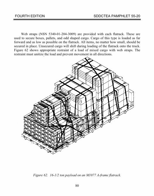
Web straps (NSN 5340-01-204-3009) are provided with each flatrack. These are
used to secure boxes, pallets, and odd shaped cargo. Cargo of this type is loaded as far forward and as low as possible on the flatrack. All items, no matter how small, should be secured in place. Unsecured cargo will shift during loading of the flatrack onto the truck. Figure 62 shows appropriate restraint of a load of mixed cargo with web straps. The restraint must unitize the load and prevent movement in all directions.
Figure 62. 16-1/2 ton payload on an M1077 A-frame flatrack.
FOURTH EDITION SDDCTEA PAMPHLET 55-20
81
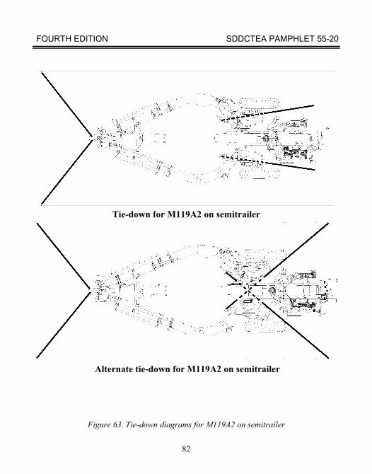
Tie-Down Procedure for M119A2 105 MM Towed Howitzer One D-shackle in each firing stay eyelet for a chain (total 2), and two independent chains through the towing eye. These chains are then fastened to the deck of a trailer or railcar. Rear tie-down chains may be crossed (only if absolutely necessary) to fixed tie-down points on the trailer bed. If chains are crossed, the MUST be separated with non-conducting material. PREPARATION, LOADING, AND TIE-DOWN ON SEMITRAILER Wood-deck semitrailer. Figure 63 shows the M119A2 in the folded configuration for transport on wood-deck semitrailers. This figure shows tie-down procedures compatible with standard loading practices that will offer adequate restraint.
Aluminum-deck semitrailer. Figure 63 shows the M119A2 in the folded configuration for transport on aluminum-deck semitrailers. Two tie-down provisions are required fore, and two tie-down provisions are required aft. Route chains through shackles inserted into the firing stay brackets and separate crossing chains with non-conducting material. Route chains through the towing eye and separate chains if in contact with non-conducting materials. Shackle specifications: 3/4 inch-D shackle per RR-C-271, Type IVA, Grade A and Grade B, Class 2. Chain specifications: chain in accordance with page 84 of this Pam that fits through the selected shackle and has a minimum Safe Working Load of 6,600 lbs.
FOURTH EDITION SDDCTEA PAMPHLET 55-20
82
Tie-down for M119A2 on semitrailer
Alternate tie-down for M119A2 on semitrailer
Figure 63. Tie-down diagrams for M119A2 on semitrailer
FOURTH EDITION SDDCTEA PAMPHLET 55-20
83
SECTION III. GENERAL FLATBED SEMITRAILER LOADS
A. TIEDOWN WITH CHAINS
Sometimes you may have to secure loads that are not listed in this book on flatbed semitrailers. Tiedown operations are simpler if you use chains and loadbinders instead of wire ropes and clamps. You should refer to the figures in section III as a general guide. Modify those procedures if necessary, to secure to the cargo or cargo vehicle.
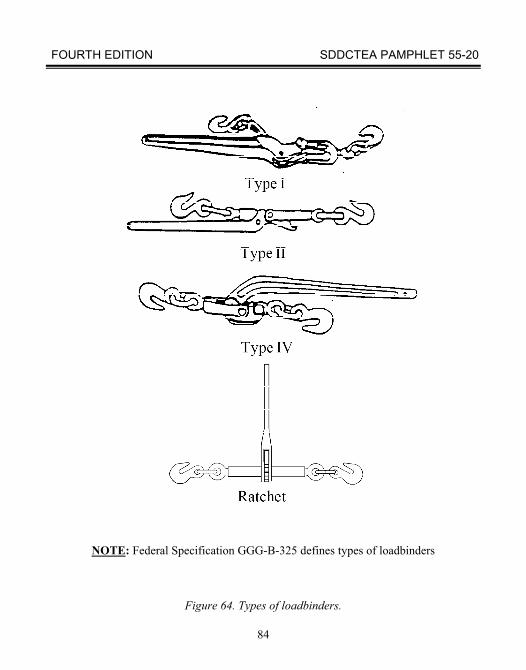
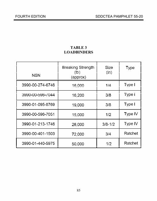
Figure 64 shows the different types of loadbinders. Tables 3 and 4 show stock numbers for some loadbinders and chains. Loadbinders are described and specified in Federal Specification GGG-B-325. The ratchet loadbinder can achieve significantly greater tiedown forces than the other types of loadbinders. Of the loadbinders shown, the ratchet and type IV are the safest. Other types of loadbinders may spring back with great force upon release. If you must use them, be very careful when releasing them. Stay clear of the swing-path of the loadbinder handle.
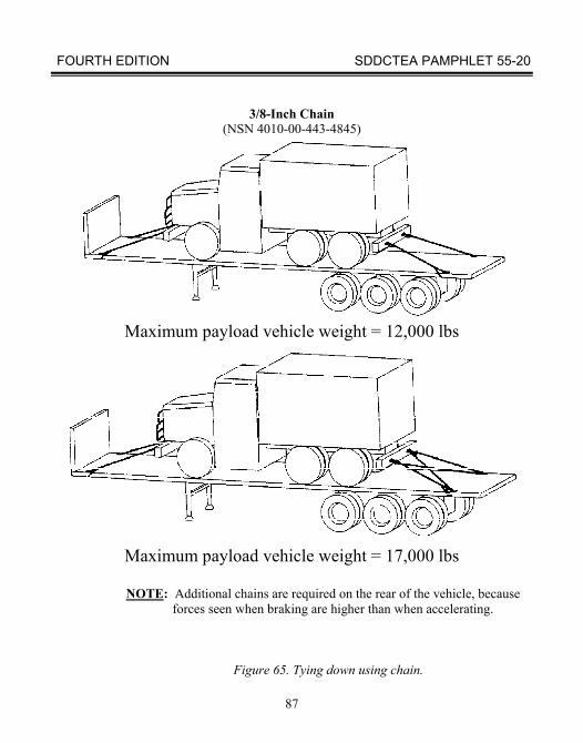
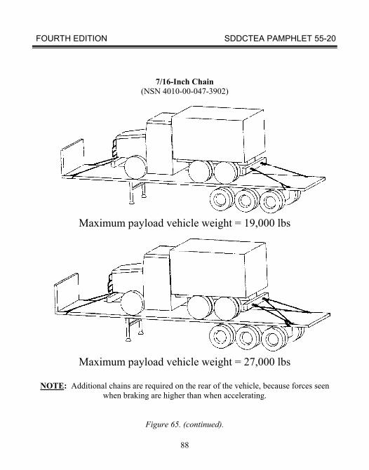
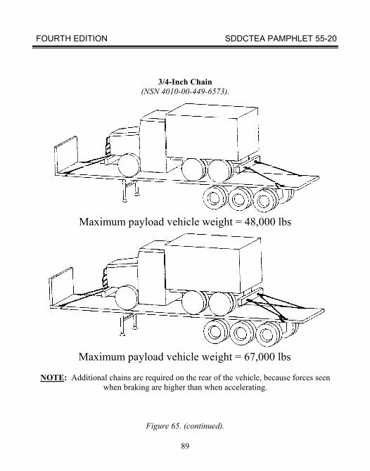
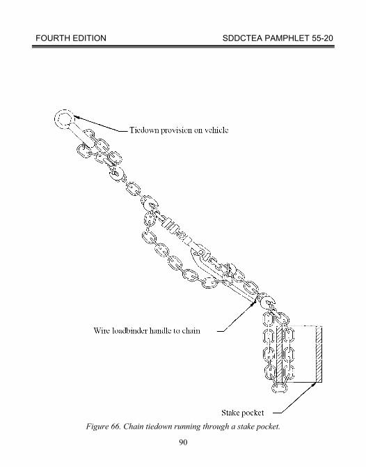
If you cannot position your load snugly against a gooseneck, use chains to provide enough forward restraint. Figure 65 provides general guidance on how many chains to use. In most cases, one additional pair of chains running from the aft tiedown provision of the payload vehicle to the semitrailer will be enough. If available, you should attach the chains to D-rings on the semitrailer. On semitrailers without D-rings, you can usually attach the chain to stake pockets (fig 66).
FOURTH EDITION SDDCTEA PAMPHLET 55-20
84
NOTE: Federal Specification GGG-B-325 defines types of loadbinders
Figure 64. Types of loadbinders.
FOURTH EDITION SDDCTEA PAMPHLET 55-20
85
TABLE 3 LOADBINDERS
FOURTH EDITION SDDCTEA PAMPHLET 55-20
86
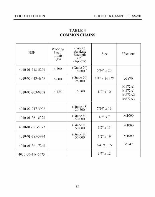
TABLE 4 COMMON CHAINS
FOURTH EDITION SDDCTEA PAMPHLET 55-20
87
3/8-Inch Chain (NSN 4010-00-443-4845)
Maximum payload vehicle weight = 12,000 lbs
Maximum payload vehicle weight = 17,000 lbs
NOTE: Additional chains are required on the rear of the vehicle, because
forces seen when braking are higher than when accelerating.
Figure 65. Tying down using chain.
FOURTH EDITION SDDCTEA PAMPHLET 55-20
88
7/16-Inch Chain
(NSN 4010-00-047-3902)
Maximum payload vehicle weight = 19,000 lbs
Maximum payload vehicle weight = 27,000 lbs
NOTE: Additional chains are required on the rear of the vehicle, because forces seen
when braking are higher than when accelerating.
Figure 65. (continued).
FOURTH EDITION SDDCTEA PAMPHLET 55-20
89
3/4-Inch Chain
(NSN 4010-00-449-6573).
Maximum payload vehicle weight = 48,000 lbs
Maximum payload vehicle weight = 67,000 lbs
NOTE: Additional chains are required on the rear of the vehicle, because forces seen when braking are higher than when accelerating.
Figure 65. (continued).
FOURTH EDITION SDDCTEA PAMPHLET 55-20
90
Figure 66. Chain tiedown running through a stake pocket.
FOURTH EDITION SDDCTEA PAMPHLET 55-20
91
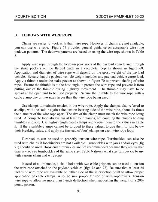
B. TIEDOWN WITH WIRE ROPE
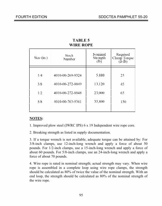
Chains are easier to work with than wire rope. However, if chains are not available, you can use wire rope. Figure 67 provides general guidance on acceptable wire rope tiedown patterns. The tiedown patterns are based on using the wire rope shown in Table 5.
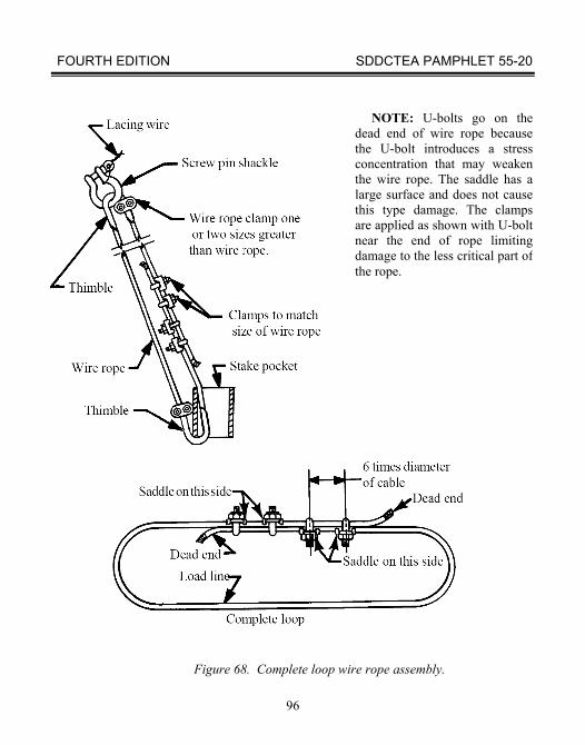
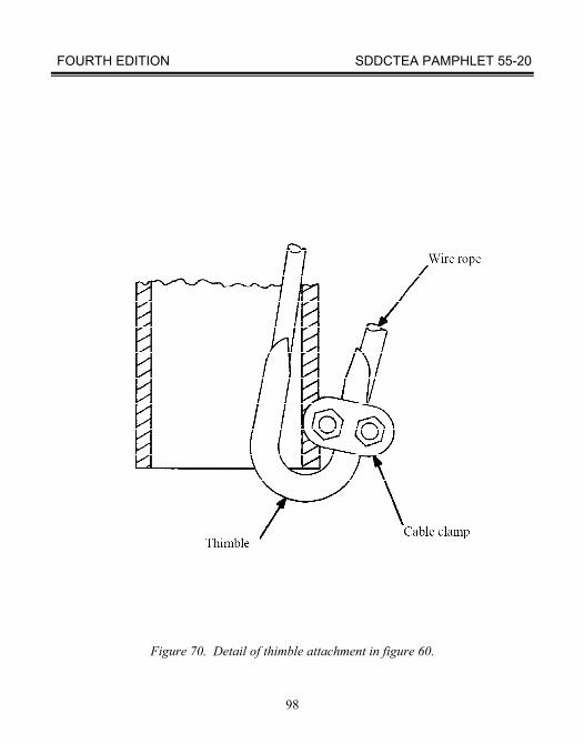
Apply wire rope through the tiedown provisions of the payload vehicle and through the stake pockets on the flatbed truck in a complete loop as shown in figure 68. Application and diameter of wire rope will depend on the gross weight of the payload vehicle. Be sure that the payload vehicle weight includes any payload vehicle cargo load. Apply a thimble under the stake pocket as shown in figure 70 to prevent chafing of wire rope. Ensure the thimble is at the best angle to protect the wire rope and prevent it from pulling out of the thimble during highway movement. The thimble may have to be spread at the open end to be used properly. Secure the thimble to the wire rope with a cable clamp one or two sizes larger than the wire rope being used.
Use clamps to maintain tension in the wire rope. Apply the clamps, also referred to as clips, with the saddle against the tension-bearing side of the wire rope, about six times the diameter of the wire rope apart. The size of the clamp must match the wire rope being used. A complete loop always has at least four clamps, not counting the clamps holding thimbles in place. Use high-strength cable clamps and torque them to the values in Table 5. If the available clamps cannot be torqued to these values, torque them to just below their breaking value, and apply six (instead of four) clamps on each wire rope loop.
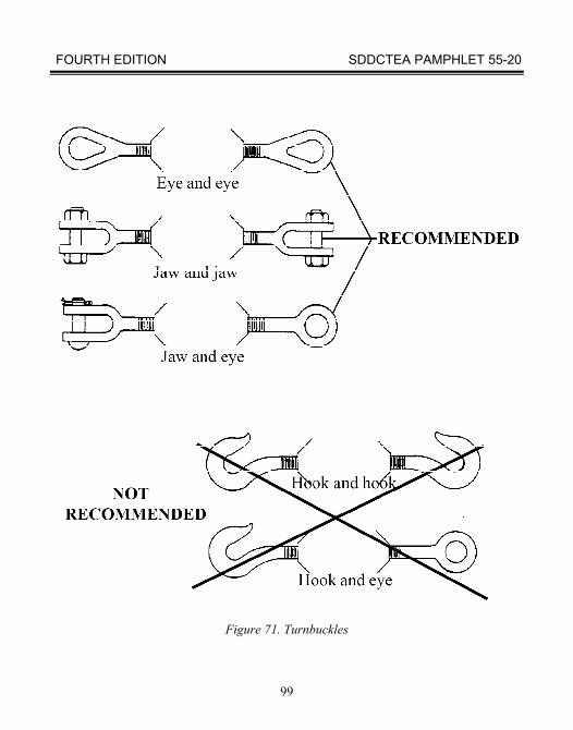
Turnbuckles can be used to properly tension wire rope. Turnbuckles can also be used with chains if loadbinders are not available. Turnbuckles with jaws and/or eyes (fig 71) should be used. Hook end turnbuckles are not recommended because they are weaker than jaw or eye turnbuckles of the same size. Table 6 shows what size turnbuckle to use with various chain and wire rope.
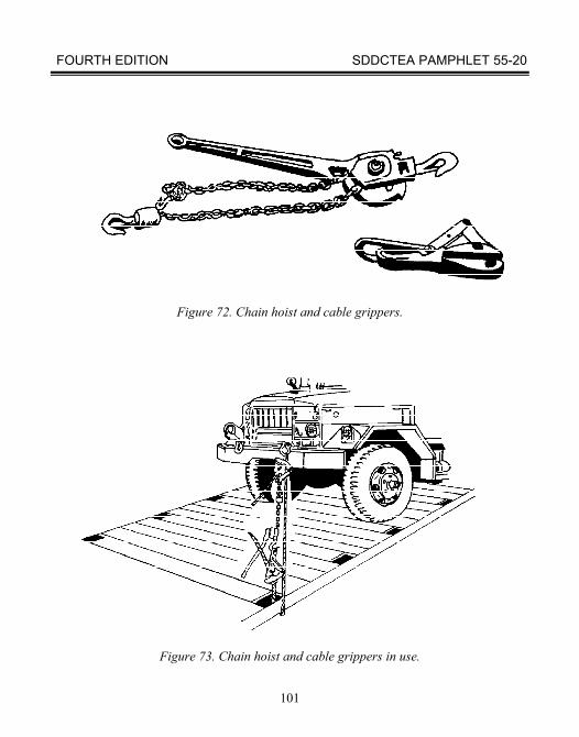
Instead of a turnbuckle, a chain hoist with two cable grippers can be used to tension the wire rope attached to the payload vehicles (figs 72 and 73). Be sure that at least 24 inches of wire rope are available on either side of the intersection point to allow proper application of cable clamps. Also, be sure proper tension of wire rope exists. Tension wire rope to allow no more than 1-inch deflection when supporting the weight of a 200-pound person.
FOURTH EDITION SDDCTEA PAMPHLET 55-20
92
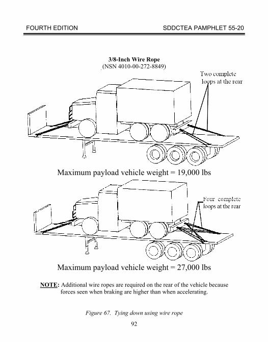
3/8-Inch Wire Rope
(NSN 4010-00-272-8849)
Maximum payload vehicle weight = 19,000 lbs
Maximum payload vehicle weight = 27,000 lbs
NOTE: Additional wire ropes are required on the rear of the vehicle because
forces seen when braking are higher than when accelerating.
Figure 67. Tying down using wire rope
FOURTH EDITION SDDCTEA PAMPHLET 55-20
93
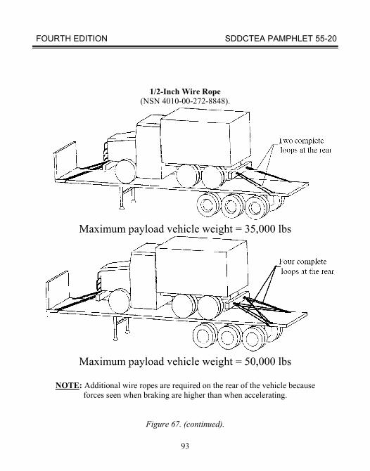
1/2-Inch Wire Rope (NSN 4010-00-272-8848).
Maximum payload vehicle weight = 35,000 lbs
Maximum payload vehicle weight = 50,000 lbs
NOTE: Additional wire ropes are required on the rear of the vehicle because
forces seen when braking are higher than when accelerating.
Figure 67. (continued).
FOURTH EDITION SDDCTEA PAMPHLET 55-20
94
5/8-Inch Wire Rope
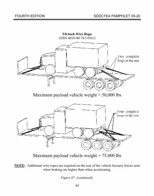
(NSN 4010-00-763-9361)
Maximum payload vehicle weight = 50,000 lbs
Maximum payload vehicle weight = 75,000 lbs
NOTE: Additional wire ropes are required on the rear of the vehicle because forces seen
when braking are higher than when accelerating.
Figure 67. (continued).
FOURTH EDITION SDDCTEA PAMPHLET 55-20
95
TABLE 5 WIRE ROPE
NOTES: 1. Improved plow steel (IWRC IPS) 6 x 19 Independent wire rope core. 2. Breaking strength as listed in supply documentation. 3. If a torque wrench is not available, adequate torque can be attained by: For 3/8-inch clamps, use 12-inch-long wrench and apply a force of about 50 pounds. For 1/2-inch clamps, use a 15-inch-long wrench and apply a force of about 60 pounds. For 5/8-inch clamps, use an 24-inch-long wrench and apply a force of about 70 pounds. 4. Wire rope is rated in nominal strength; actual strength may vary. When wire rope is assembled in a complete loop using wire rope clamps, the strength should be calculated as 80% of twice the value of the nominal strength. With an end loop, the strength should be calculated as 80% of the nominal strength of the wire rope.
FOURTH EDITION SDDCTEA PAMPHLET 55-20
96
Figure 68. Complete loop wire rope assembly.
NOTE: U-bolts go on the dead end of wire rope because the U-bolt introduces a stress concentration that may weaken the wire rope. The saddle has a large surface and does not cause this type damage. The clamps are applied as shown with U-bolt near the end of rope limiting damage to the less critical part of the rope.
FOURTH EDITION SDDCTEA PAMPHLET 55-20
97
Figure 69. Single strand wire rope assembly.
FOURTH EDITION SDDCTEA PAMPHLET 55-20
98
Figure 70. Detail of thimble attachment in figure 60.
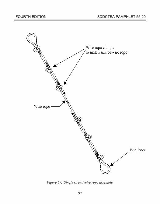
FOURTH EDITION SDDCTEA PAMPHLET 55-20
99
Figure 71. Turnbuckles
FOURTH EDITION SDDCTEA PAMPHLET 55-20
100
FOURTH EDITION SDDCTEA PAMPHLET 55-20
101
Figure 72. Chain hoist and cable grippers.
Figure 73. Chain hoist and cable grippers in use.
FOURTH EDITION SDDCTEA PAMPHLET 55-20
102
C. TIEDOWN WITH WEB STRAP
Web straps are easy to use to secure boxes and pallets for transport. The web straps, easily obtained from the Army inventory (NSN 1670-00-725-1437 and NSN 5340-01-204-3009, fig 74), are rated at 5,000 pounds.
Before each use, straps should be inspected for burns, tears, punctures, cuts, caustic damage, oil or grease contamination, and fraying or broken stitches. Also, their metal parts should be inspected for improper operation, corrosion, cracks, or distortion. If any of these conditions exist, the tiedown should be replaced. They should not be used for any mode of transport if they have been damaged. No strength testing of straps will be made.
When tiedown straps are attached to cargo and to vehicle tiedown fittings, each strap
must be tensioned to form at least 1-1/2 turns on the takeup spool of the tensioning ratchet. The 1-1/2 turns must take place after webbing-to-webbing contact. To prevent movement of the cargo, each tiedown must be tightened until about equal tension is applied throughout the tiedown arrangement. After tensioning is completed, the takeup spool locking latch must be checked to ensure that it is fully seated at both ends of the spool in the matching locking notches. The scuff sleeve may have to be removed to allow tightening of tiedowns. Secure the loose ends of straps by suitable means.
When using web straps to secure loads on pallets, you may need to place padding between the load and the hooks to prevent the hooks from damaging the load. Figure 75 shows typical loads secured to the cargo bed of the vehicle with web straps. Steel banding is used to secure the items together. Figure 76 shows how to use web straps or steel banding to secure a load to a pallet.
FOURTH EDITION SDDCTEA PAMPHLET 55-20
103
Figure 74. Web strap (NSN 5340-01-204-3009).
The image cannot be displayed. Your computer may not have enough memory to open the image, or the image may have been corrupted. Restart your computer, and then open the file again. If the red x still appears, you may have to delete the image and then insert it again.
FOURTH EDITION SDDCTEA PAMPHLET 55-20
104
Figure 75. Typical loads secured with web straps.
FOURTH EDITION SDDCTEA PAMPHLET 55-20
105
Figure 76. Palletized load using web straps or steel banding.
FOURTH EDITION SDDCTEA PAMPHLET 55-20
106
D. TIEDOWN WITH STEEL BANDING
Steel banding is an effective way to secure a load for transport, if you have the equipment to tighten the straps and crimp the bands. This type of banding can be used for all modes of transport. Rail transport is the only mode that has specific requirements for steel bands and crimping the bands. If the band requirements meet rail transport they will not have to be changed during transport. Figure 76 shows the different types of crimps approved for rail transport and appropriate for highway transport. The railroad banding requirements generally reflect proper band application as developed by the band manufacturing industry. When used during rail transport, steel banding must be approved by the Association of American Railroads and labeled as required. The banding suppliers should be aware of these requirements. Figure 77 shows a typical load secured to a cargo bed of a vehicle. Blocking is typically used to prevent the load from moving longitudinally and laterally. Steel banding is also good for binding together several items with identical dimensions without blocking.
Blocking can be nailed directly to wood deck semitrailers or it must be against the
end and side walls of the cargo vehicle to prevent it from shifting during transport.
FOURTH EDITION SDDCTEA PAMPHLET 55-20
107
CRIMP TYPE TIE JOINT
Figure 77. Illustration of steel band notch and crimp type seal joints.
FOURTH EDITION SDDCTEA PAMPHLET 55-20
108
Figure 78. Typical load secured with steel straps and strap anchoring detail.
FOURTH EDITION SDDCTEA PAMPHLET 55-20
109
SECTION IV. PAYLOAD VEHICLE TIEDOWN TIPS A. PREPARING PAYLOAD VEHICLES PRIOR TO LOADING
1. Be sure that all shackles are on the vehicle. Do not use bumperettes, axles, towing pintles, or towing hooks as points of attachment for chains. 2. Be sure fuel tanks of payload vehicles are no more than three-fourths full. 3. Remove or band canvas and bows to prevent wind damage. 4. Protect windshields of payload vehicles if needed. 5. Reduce payload vehicles to their lowest height configuration consistent with the operational requirements and unit standing operating procedures. 6. Secure any materials or equipment loaded in the beds of cargo vehicles by banding, chains, or cargo straps. 7. Remove all sensitive or pilfer able items that cannot be secured.
B. LOADING PAYLOAD VEHICLES
1. Make sure tractor and semitrailer parking brakes are on to assure maximum vehicle stability during drive-on operation. 2. If vehicle is on a grade, block the downhill side of wheels. 3. Put blocks under the M747 rear frame if loading payloads of more than 55 tons (fig 31). 4. Position a guide in a prominent location to assure constant visual contact with payload vehicle driver. 5. Position a ground guide off the rear corner of semitrailer to maintain visual contact with guide in the prominent forward location.
FOURTH EDITION SDDCTEA PAMPHLET 55-20
110
6. Warn personnel to stay clear of the semitrailer during loading operations. Ensure personnel are in no danger during loading. 7. When loading the M747 or M1000, put curbing in the proper positions. 8. When loading any firm-tracked vehicle such as a crane or bulldozer onto an M747 or M1000, attach towing vehicle winch cables to towing lugs of payload vehicle as a safety precaution. Operate towing vehicle winches to try to keep cable under even tension at all times to prevent payload from tipping or rolling backwards and to assist payload during breakover at top of ramp. Rig cables for payload weight. When loading a crane, turn crane counterbalance to forward end. 9. Shut payload vehicle down, turn off all switches, close doors and hatches, and swing in mirrors. Make sure all items are secure on payload to prevent them from falling off during transport. 10. Observe other special procedures when loading and securing heavy tracked vehicles on M747 or M1000 semitrailers (see previous sections on these semitrailers).
FOURTH EDITION SDDCTEA PAMPHLET 55-20
111
C. SECURING PAYLOAD VEHICLES
1. Make sure wood bumpers are on the M747 gooseneck for all single vehicle loads. Use wood dunnage on M870 and M172A1 goosenecks when a portion of the payload vehicle will contact the gooseneck (fig79). Avoid metal-to-metal contact. 2. Make sure curbing is properly located against payload tracks on M747 and M1000 semitrailers. After payload is on the M747, move curbs from position F to position A (or store them if not needed in position A). 3. Tighten chains using the loadbinders. 4. Secure excess chain to the tension-bearing part of the chain. 5. On chain devices, secure open-faced hooks to the chain link with wire. 6. Lock chain tightening devices with wire. Tighten jamnuts on turnbuckles with a wrench. 7. Set brakes on payload vehicles and put their transmissions in neutral. 8. Make sure gun turrets or other rotating parts are properly secured. 9. Make sure the retractable clearance lights are in the retracted position for regular loads or are extended for all loads wider than the semitrailer bed. 10. Make sure ramps are raised and properly secured. 11. Make sure all basic issue items are properly stowed on the semitrailer. 12. Check the tractor and the semitrailer brakes and all lights to make sure they are operating.
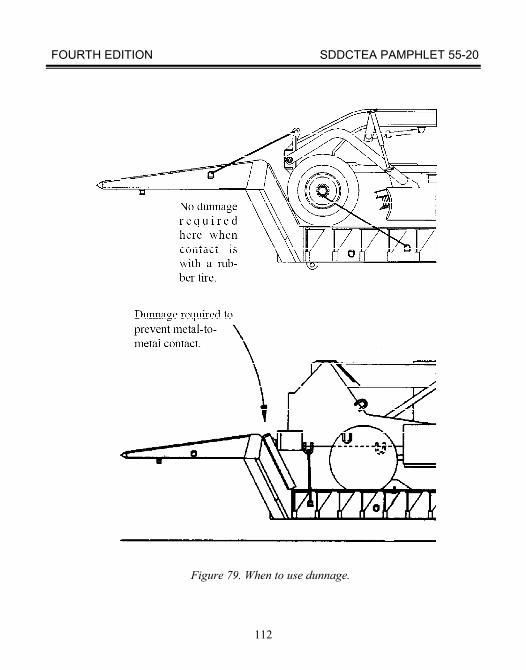
FOURTH EDITION SDDCTEA PAMPHLET 55-20
112
Figure 79. When to use dunnage.
FOURTH EDITION SDDCTEA PAMPHLET 55-20
113
13. Check all tiedowns at the first opportunity after departure. If possible, plan a check within the first 2 miles of your trip. Recheck all tiedowns at halts and at any time you suspect a problem.
D. TOOLKIT
Loading and tiedown operations will be easier if the proper tools are readily available. Table 7 contains a list of recommended tools. Tables 3, 4, and 5 show national stock numbers of common chain assemblies, loadbinders, and wire rope.
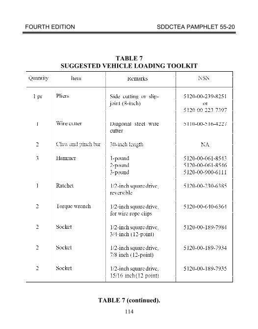
FOURTH EDITION SDDCTEA PAMPHLET 55-20
114
TABLE 7
SUGGESTED VEHICLE LOADING TOOLKIT
TABLE 7 (continued).
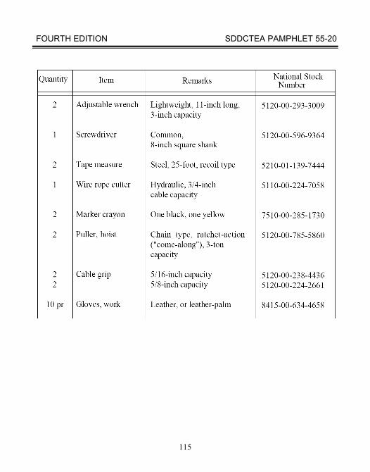
FOURTH EDITION SDDCTEA PAMPHLET 55-20
115
FOURTH EDITION SDDCTEA PAMPHLET 55-20
116
SECTION V. FORSCOM CARGO FORMS
A. GENERAL
When loading organic cargo onto a vehicle, certain forms must be completed and maintained.
This section is a general guide for the use of FORSCOM Form 285-R, Vehicle Load Card and DD Form 1750, Packing List. Refer to FORSCOM/ARNG Reg 55-1, Unit Movement Planning, for more detailed guidance. B. FORSCOM FORM 285-R
FORSCOM Form 285-R (fig 80) is used for developing and recording a unit’s organic vehicle cargo load and is included in the unit’s movement plan. It will reflect a general description and location of all items in the cargo bed to include boxed/crated items. Information on dimensions, weights, and cubes for all Army equipment is contained in the CD-ROM and worldwide web versions of TB 55-46-1. The following general guidance is provided to assist in completing this form:
1. Drivers and assistant drivers are not normally added to the weight of the vehicle. However, on HMMWVs and CUCVs, all personnel on board, including drivers and assistant drivers, must be computed as part of the payload to avoid overloading the vehicle. 2. When transporting personnel in the cargo compartment, a planning factor of 245 pounds for each soldier will be used.
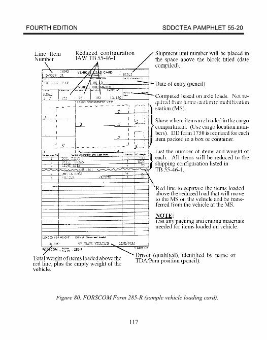
FOURTH EDITION SDDCTEA PAMPHLET 55-20
117
Figure 80. FORSCOM Form 285-R (sample vehicle loading card).
FOURTH EDITION SDDCTEA PAMPHLET 55-20
118
3. Duffle bags (A and B) will be estimated at 70 pounds each. 4. Twenty two inches of width will be used per person transported in the cargo compartment of the vehicle. 5. Generally, vehicles will have no more than a three-fourths tank of fuel if they are to be shipped by air, rail, or sea. 6. The shipment unit number (SUN) is found on the unit’s Automated Unit Equipment List (AUEL)/Deployment equipment List. 7. The date block is completed in pencil to allow for periodic updating. 8. The vehicle LIN and Index Number entered on this form should be the same as entries on the AUEL. The LIN number corresponds to the vehicle model. The index number corresponds to the vehicle/load configuration. 9. The cargo compartment view is not a picture of the vehicle being loaded, but a portrayal of the load on the vehicle. 10. The cargo location number correlates to the location of the numbered piece of cargo on the load diagram. 11. The unit should enter as much information as is needed in the Cargo Description and Type Pack blocks to describe the cargo. 12. To compute total weight, the unit multiplies the number from the Number of items column by the quantity in the Piece Weight column.
13. For Reserve Component units, items listed below the red line will be offloaded at the mobilization station and shipped by commercial transportation. For Active Component units, the loaded vehicle weight is computed by adding the empty weight of the vehicle to all the items listed on the card. The total weight must never exceed the rated capacity of the vehicle.
FOURTH EDITION SDDCTEA PAMPHLET 55-20
119
In the upper right-hand corner of the FORSCOM Form 285-R is the shipment unit number. This number is found on your Automated Unit Equipment List (AUEL). On the left side you could further identify your vehicle by inserting the line item number and/or index number. Complete the unit and bumper number blocks with the appropriate information. The date compiled block is filled out in pencil because changes may occur.
The vehicle information blocks are probably the most misunderstood entries on the
form. For mobilization vehicle information, you must always refer to chapter 3 of TB 55-46-1. Determine if your vehicle has a load; this information is needed to research the appropriate index number. The information from this part of the FORSCOM Form 285-R should be exactly the same as entries on the AUEL. That is provided by the Unit Movement Officer to the Installation Transportation Officer. The beginning of chapter 3 in TB 55-46-1 contains information on how to use the rest of the chapter.
The cargo compartment view is not a picture of the vehicle you are loading, but a
portrayal of the load on the vehicle. When filling this out, keep in mind that the individual unloading this vehicle may not be the individual who loaded it. How do you reflect multiple levels of equipment on a card? There is no single correct answer; use whatever you can devise to clearly identify the layers. If you look at the example in figure 72, you will see that we used a broken line to depict the second layer. As an option, you could take a photograph of the load once it is complete, and submit it with the FORSCOM Form 285-R. Remember, keep it simple and legible; that’s the key.
FOURTH EDITION SDDCTEA PAMPHLET 55-20
120
The cargo location number is the most exact location of a piece of cargo on the load. When you get to the cargo description and type pack, enter as much information as is needed to identify what is located there. The quantity column is the number of pieces found at that cargo location. Remember:
1. Ensure that only the piece weight is entered in this column. 2. When adding up the total weight, multiply the number from the quantity column by the quantity in the piece weight column.
This takes us to the lower left hand side of the form. The loaded vehicle weight is computed by taking the empty weight of the vehicle and adding to it everything above the red line. Everything that is below the red line will be removed at the mobilization site and shipped by commercial transportation. The most important thing you must remember about this entry is that the total weight must never exceed the rated capacity of the vehicle. In the driver block, enter the driver's name or line/paragraph. C. DD FORM 1750
DD Form 1750 (fig 81) is a packing list prepared by the unit for all consolidated
cargo loaded in vehicles, containers, and on 463L pallets moving commercially or on organic transportation. Once deployment begins, copies of the packing list are distributed as follows:
a. One inside the container. b. One on the outside of the container (exception - containers with sensitive items) c. Two copies retained by unit representatives at POE. d. One with the Unit Movement Plan. e. One provided to UMO/ITO for commercial shipments.
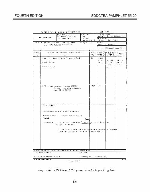
FOURTH EDITION SDDCTEA PAMPHLET 55-20
121
Figure 81. DD Form 1750 (sample vehicle packing list).
FOURTH EDITION SDDCTEA PAMPHLET 55-20
122
Installations may request additional copies. Packing lists are not required for items that do not need identification (such as empty vehicles, nested cans, or bundled shovels). However, these items must be listed on the load diagram if loaded in a truck or container. A packing list is not required for a container already having a list of contents affixed to it, such as inventories of tools or parts found in supply bulletins. The packing list will be placed on both the inside and outside of the container. The exception is for sensitive items. Sensitive items will not be listed on a packing list on the outside of the container. However, the UMO will notify the ITO that sensitive items are being shipped by completing a DD Form 1907 (Signature and Tally Record). It will accompany the GBL to create a “chain-of-custody” IAW DoD Reg 4500.9-R, Part II.
NOTE: DA Form 5748-R, Shipment Unit Packing List and Load Diagram, is an authorized substitute for DD Form 1750 and FORSCOM Form 285-R.
The following general guidance is provided to assist in completing this form: 1. Block 1 reflects the number of box/boxes (if used asa consolidated list). 2. Block 2a is the vehicle number. 3. Block 2b is the SUN. 4. Block 3 (End item) contains the description of the contents of the container/box/ pallet. 5. Blocks (d), (e), and (f) reflect the “Packs,” “Weight,” and “Total Weight,” respectively. The Total Weight column is the total for that line only. The “Total Weight” at the bottom of the form is the cumulative weight of all the contents. 6. The blocking, bracing, packing, crating, and tiedown materials (BBPCT) are entered under the contents column and the weight added to the total. 7. The description of container and bumper number entries identify the container/ vehicle on which the load is carried. 8. The primary or alternate UMO must certify the load by signing block 6.
FOURTH EDITION SDDCTEA PAMPHLET 55-20
123
ACRONYMS
Acronym Definition AUEL Automated Unit Equipment List BBPCT Blocking, Bracing, Packing, Crating, and Tiedown BII Basic Issue Item CG Center of Gravity CHE Container Handling Equipment CROP Container Roll-in/Out Platform DAC Defense Ammunition Center DD Department of Defense FM Field Manual FMTV Family of Medium Tactical Vehicles FORSCOM Forces Command HET Heavy Equipment Transporter HMMWV High Mobility Multi-Purpose Wheeled Vehicle HYEX Hydraulic Excavator ITO Installation Transportation Officer IAW In Accordance With

FOURTH EDITION SDDCTEA PAMPHLET 55-20
124
ACRONYMS
Acronym Definition LIN Line Item Number NSN National Stock Number MHC Materials Handling Crane MHE Materials Handling Equipment MS Mobilization Station MTMCTEA Military Traffic Management Command Transportation Engineering Agency
PLS Palletized Load System SDDCTEA Military Surface Deployment and Distribution Command Transportation Engineering Agency SUN Shipment Unit Number TB Technical Bulletin TDA Table of Distributions and Allowances TM Technical Manual UMO Unit Movement Officer USMC United States Marine Corps VRRTFL Variable Reach Rough Terrain Forklift

FOURTH EDITION SDDCTEA PAMPHLET 55-20
125
Notes

FOURTH EDITION SDDCTEA PAMPHLET 55-20
126
Notes