truck hydraulics - hydraulic engineering company |...
TRANSCRIPT

Truck HydraulicsSeries GPA, GP1, F1, F2, T1, VP1, Fixed and Variable Displacement Pumps, Motors and Accessories

2 Parker HannifinPump and Motor DivisionTrollhättan, Sweden
Catalogue HY30-8200/UK
Conversion factors1 kg ................................................................. 2,20 lb
1 N ............................................................... 0,225 lbf
1 Nm ......................................................... 0,738 lbf ft
1 bar ..............................................................14,5 psi
1 l ......................................................0,264 US gallon
1 cm3 ........................................................0,061 cu in
1 mm ............................................................. 0,039 in9/5 °C + 32 ............................................................1°F
1 kW .............................................................. 1,34 hp
Truck HydraulicsPumps and Motors
FAILURE OR IMPROPER SELECTION OR IMPROPER USE OF THE PRODUCTS DESCRIBED HEREIN OR RELATED ITEMS CAN CAUSE DEATH, PERSONAL INJURY AND PROPERTY DAMAGE.
This document and other information from Parker-Hannifin Corporation, its subsidiaries and authorized distributors provide product or system options for further investigation by users having technical expertise.
The user, through its own analysis and testing, is solely responsible for making the final selection of the system and components and assuring that all performance, endurance, maintenance, safety and warning requirements of the application are met. The user must analyze all aspects of the application, follow applicable industry standards, and follow the information concerning the product in the current product catalog and in any other materials provided from Parker or its subsidiaries or authorized distributors.
To the extent that Parker or its subsidiaries or authorized distributors provide component or system options based upon data or specifications provided by the user, the user is responsible for determining that such data and specifications are suitable and sufficient for all applications and reasonably foreseeable uses of the components or systems.
Offer of SalePlease contact your Parker representation for a detailed ”Offer of Sale”.
WARNING – USER RESPONSIBILITY

3 Parker HannifinPump and Motor DivisionTrollhättan, Sweden
Catalogue HY30-8200/UK
1
2
3
4
5
6
7
8
9
10
11
12
13
General Information General InformationGeneral information, design Page 4 - 10
Pump and line selection Pump and line selectionInstallation guide lines Page 11 - 14
GPA and GP1 GPA and GP1Fixed Displacement - Gear Pumps Page 15 - 20
F1 Pump F1Fixed Displacement - Axial Piston Pump. ISO and SAE version Page 21 - 31
F1 Motor F1Fixed Displacement - Axial Piston Motor. Page 32 - 33
F2 Twin-flow pump F2Fixed Displacement - Axial Piston Pump Page 34 - 36
T1 Pump T1Fixed Displacement - Axial Piston Pump. Page 37 - 40
VP1 Pump VP1Variable Displacement - Axial Piston Pump Page 41 - 48
BLA BLABoost units Page 49
Fittings FittingsSuction fittings and fitting kits Page 50 - 51
Auxiliary Valves Auxiliary ValvesBypass Valve and Unloading Valve Page 52 - 61
Accessories AccessoriesUniversal PTO air valve kits, PTO adapter kits for engines, Cardan shafts, pump couplings and mounting brackets, SB splitter boxes Page 62 - 70
Installation and start up Installation and start upGPA, GP1, F1, F2, T1 and VP1 Page 71 - 75
ContentsTruck HydraulicsPumps and Motors

4 Parker HannifinPump and Motor DivisionTrollhättan, Sweden
Catalogue HY30-8200/UK Truck HydraulicsPumps and Motors
GPA and GP1 Pumps
Light/medium duty pumpsParker’s truck gear pumps are ideal for operators of light trucks for their hydraulic power needs.
The GPA/GP1 series gear pumps are available to suit most applications. They are light and compact, and can be installed in either rear or or side mount configu-ration thanks to their unique dual port layout.
The smaller GPA series is built with an extruded alumi-num houising for minimum weight.
The larger GP1 pumps are built with compact cast iron housings for strength.
The gear pumps complement our heavy duty piston pumps and vane pumps.
The performance and characteristics are ideal for many light and/or intermittent applications, including the famous Parker reliability, and they are engineered with a long, trouble-free service life.
Features• Compactandlightweight-easytoinstallevenon
small vehicles
• Quietoperation-lownoiseemissionsareimportantin sensitive areas
• Robustandreliable-meansalong,trouble-free service life
• Builtforhighrpm’s-lesssensitivetoover-speeding
• Bi-directional-easytoinstall
• Sideorrearmount-usetheportsonthesideoratthe rear, whichever is most suitable for the applica-tion.
See page 15
Series GPA
Series GP1
General Information

5 Parker HannifinPump and Motor DivisionTrollhättan, Sweden
Catalogue HY30-8200/UK
1
45˚
Piston_locking.epsLeif A./990806
Piston_head.epsLeif A./990806
F1 Pump ISO
F1 piston with laminated piston ring.
F1 piston-to-shaft locking.
Series F1 is a further development of our well known 'truck pump', the F1. The F1 offers many additional val-ues for operators of cargo cranes, hook loaders, skip loaders, forest cranes, concrete mixers and similar truck applications.Series F1 is a very efficient and straight forward pump design with unsurpassed reliability. Its small envelope size gives a simple and inexpensive installation.
Features of the F1 are:• Highselfprimingspeeds• Operatingpressuresupto400bar• Highoverallefficiency• Lownoiselevel• Smallinstallationdimensions• Lowweight
... thanks to:- 45° bent-axis angle- Optimal inlet port geometry in the end cap- Single housing design- Spherical pistons - high speeds- Laminatedpistonrings-lowleakage- Positive synchronisation with timing gear- Installation above the reservoir level possible- Tolerates low temperatures and high
temperature shocks- Shaft end and mounting flange meet the ISO standard for all sizes
See page 21
Truck HydraulicsPumps and MotorsGeneral Information

6 Parker HannifinPump and Motor DivisionTrollhättan, Sweden
Catalogue HY30-8200/UK
F1 Pump SAE
F1 Motor ISO
Features:• Laminatedpistonrings-lowleakage• Positivesynchronisationwithtiminggear• Operatingpressureupto350bar• Installationabovethereservoirlevelpossible• Tolerateslowtemperaturesandhigh
temperature shocks• Shaftendandmountingflangemeetthe standard SAE-B • 4sizes-25/-41/-51/-61cm3/rev
See page 29
Features:• Laminatedpistonrings-lowleakage• Positivesynchronisationwithtiminggear• Operatingpressureupto250bar• Tolerateslowtemperaturesandhigh
temperature shocks• Shaftendandmountingflangemeetthe ISO standard for all sizes• Tolerateshighacceleration
See page 32
General InformationTruck HydraulicsPumps and Motors

7 Parker HannifinPump and Motor DivisionTrollhättan, Sweden
Catalogue HY30-8200/UK
1F2 Twin-flow pump
Series F2 is a further development of the twin-flow ver-sion of series F1, the very first bent-axis truck pump on the market to feature two entirely independent flows.With a suitable build-up of the hydraulic system, the main advantage with a twin-flow pump is that three dif-ferent flows can be provided at the same engine speed.The twin-flow pump makes it possible to further optimise the hydraulic system and offers:• Lessenergyconsumption• Reducedriskofsystemoverheating• Lowerweight• Easierinstallation• Standardisedsystemsolutions
The twin-flow pump makes it possible to operate two work functions that are independent of each other which leads to higher speed and an increased operating preci-sion.Another requirement can be a large and a small flow, or two equal flows. All of these alternatives are possible with the twin-flow pump.The pump can be utilised to provide one flow at high system pressure, and, as soon as the pressure has decreased sufficiently, add the flow from the other cir-cuit.This eliminates the risk of exceeding the PTO power rating and, at the same time, provide an optimal driving function.
See page 34
Typical twin-flow applications• Largetruckloaders• Forestrycranes• Hookloaders/liftdumpers• Tipper/cranecombinations• Refusecollectingvehicles
The pump shaft end/mounting flange meets the ISO standard and suits PTO direct mounting.
General InformationTruck HydraulicsPumps and Motors

8 Parker HannifinPump and Motor DivisionTrollhättan, Sweden
Catalogue HY30-8200/UK
T1 Pump
The T1 fixed displacement pump is a further develop-ment of series T1, which was specifically designed to meet the requirements of light duty truck applications with short, non-frequent operating cycles such as tip-pers, and small loaders.The design is very similar to that of the F1 series pumps but is even more compact. It utilises our well proven 45° concepts with spherical pistons and laminated piston rings, offering high volumetric and mechanical efficien-cies and, thanks also to the small number of parts, unprecedented reliability.
• Shaftspeedto2300rpm• Operatingpressureupto350bar• Highoverallefficiency• Lowweight• Smallinstallationdimensions• Robustconstruction
The T1, with shaft and mounting flange configuration conforming to the European standard, can be installed on most European truck gearboxes. Suitable power-take-offs are also available from Parker Hannifin.
See page 37
Typical T1 applications• Frontendtippers• Underbodytippers• Hydraulicsysteminfrequentlyusedandwithshort
cycle times.
General InformationTruck HydraulicsPumps and Motors

9 Parker HannifinPump and Motor DivisionTrollhättan, Sweden
Catalogue HY30-8200/UK
1VP1 Pump
DesignLarge angle - compact designThe pump design permits a large angle, 20°, between piston and slipper shoe/swashplate, providing compact-ness and small outer dimensions.
Tandem couplingThe through-shaft on VP1-45/-75 permits tandem cou-pling of an additional pump, such as a series F1 fixed displacement pump.
Long lifeThe VP1 is designed for trucks with hydraulic load sens-ing systems. It is sturdy, yet simple, with few moving parts. The result is a reliable pump with long service life.
See page 41
The VP1 is a variable displacement pump for truck applications. It can be close-coupled to a gearbox PTO (power take-off) or to a coupling independent PTO (e.g. an engine PTO) which meets ISO standard 7653-1985. An application that makes full use of all the features of the VP1 is truck cranes with a load sensing system. The complex systems of refuse collection vehicles and sew-age trucks as well as various combinations of tippers, cranes, snow ploughs, and salt/sand spreaders can also be greatly simplified and optimised with the VP1 pump.The VP1 provides the hydraulic system with the correct amount of fluid at precisely the right moment, effectively reducing energy consumption and heat generation. This means a smoother and quieter hydraulic system with much reduced impact on the environment.The VP1 is highly efficient and extremely light. It is reli-able, economical and easy to install.The four frame sizes, VP1-045, -075, -095 and -130 have small installation dimensions.
The VP1 is suitable for all load sensing systems, regardless of make.
Features• Variabledisplacement• Lownoiselevel• Highpower-to-weightratio• Compactandlight• Highlyefficient• Sturdydesign• Withstandslowtemperatures• Canbeclosecoupledandtandemmounted. (tandem coupling only for VP1-45/-75)
Retainer plateThe retainer plate (refer to the cut-away illustration in chapter 8) is of a heavy duty design which makes the pump withstand high shaft speeds and fast speed changes.(e. g. engine PTO).
General InformationTruck HydraulicsPumps and Motors

10 Parker HannifinPump and Motor DivisionTrollhättan, Sweden
Catalogue HY30-8200/UK
Accessories
Adaptor kits and accessories for F1, F2, T1 and VP1 pumps
BLABoost unit. See chapter 9.
FittingsSuction fittings and fitting kitsSee chapter 10.
Bypass valveBPV-F1/-T1, BPV-F1-25 and 81, BPV-F2, See chapter 11.
Unloading valveBPV-VP1,BPV-L.See chapter 11.
AccessoriesUniversal PTO air valve kits, PTO adapter kits for engines, cardan shafts, pump couplings and mounting brackets, and splitter boxes (SB 1-1,18, 1-1,54)
See chapter 12.
F1plus_access.epsLeif A./00-07-07
1
3
2
NOR
MA
LR
UN
NIN
GCHANGE FILTER
R L
ROTATION
Truck HydraulicsAccessoriesGeneral Information

11 Parker HannifinPump and Motor DivisionTrollhättan, Sweden
Catalogue HY30-8200/UK
1
2
Pump and Line selection
Installation guide lines for GPA, GP1, F1, F2, T1 and VP1 pumps
Truck HydraulicsPump and Line selectionContents
Contents Page
Pump selection
F1 and T1 .....................................................................................................12
Line selection
all pumps ......................................................................................................13
Nomogram ....................................................................................................14

12 Parker HannifinPump and Motor DivisionTrollhättan, Sweden
Catalogue HY30-8200/UK
Flow and torque formulas (no regard to efficiency)
Flow:Q= [l/min]
where:Dispumpdisplacement[cm3/rev] nisshaftspeed[rpm]
Torque:M= [Nm]
where:Dispumpdisplacement[cm3/rev] pisutilisedpressure[bar]
D x p63
D x n1000
PTOgear Enginespeed Pumpflow[l/min] ratio [rpm] T1-81 T1121 F1-25 F1-41 F1-51 F1-61 F1-81 F1-101
1:0.8 800 16 26 33 38 52 66 76 900 18 29 37 43 59 74 85 1000 20 33 41 48 65 82 95 1100 23 36 45 52 72 91 104 1200 25 39 49 57 78 99 114
1:1.0 800 20 33 41 48 65 82 95 900 23 37 46 54 73 93 107 1000 26 41 51 60 82 103 119 1100 28 45 56 65 90 113 130 1200 31 49 61 71 98 123 142
1.1.25 800 26 41 51 60 82 103 119 900 29 46 57 67 92 116 133 1000 32 51 64 74 102 129 148 1100 35 56 70 82 111 141 163 1200 38 61 77 89 122 154 178
1:1.5 800 31 49 61 71 98 123 142 900 35 55 69 80 110 139 160 1000 38 61 77 90 122 154 178 1100 42 67 84 98 135 170 196 1200 46 74 92 107 147 185 213
Pump selection F1 and T1
The following table shows pump flow at selected PTO gear ratios and engine rpm's.
Truck HydraulicsGPA, GP1, F1, F2, T1 and VP1
NOTE: - Make sure max torque and bending moment (due to the weight of the pump) of the utilised PTO are not exceeded. (The approx. center of gravity of the various pump sizes are shown in the installation drawings).
- Make sure max allowed output torque from the PTO is not exceeded.
- Contact Parker Hannifin if the inlet (suction) pressure is believed to be less than 1.0 bar (absolute); insufficient inlet pressure can cause noise and pump damage because of cavitation.
Pump and Line selection

13 Parker HannifinPump and Motor DivisionTrollhättan, Sweden
Catalogue HY30-8200/UK
2
Line selectionall pumps
Truck HydraulicsGPA, GP1, F1, F2, T1 and VP1
A suitable pump size for a truck application can be selected as follows:
Operating conditionsAs an example, a cargo crane specifies:
•Flow:60-80l/min Pressure: 230 bar Diesel engine speed ≈ 800 rpm
Determine pump speedAsexampleaPTOwithaGearRatioof1:1.54.
The pump speed will be:
•800x1.54≈ 1200 rpm
Select a suitable pump sizeUse diagram 1 and select a pump that will provide 60 - 80 l/min at 1200 rpm.
Follow line 'a' (1200 rpm) until it crosses line 'b' (70 l/min).
•F1-61isasuitablechoice
Required input torqueMake sure the PTO and the gear-box tolerates the pump torque. Use diagram 2 to obtain the required pump torque.
Follow a line from 'c' (230 bar) until it crosses the F1-61 line (the selected pump).
•Read220Nm(at'd')
NOTE: A rule-of-thumb is to select the highest PTO ratio and the smallest pump size that meets the crane specifica-tion without exceeding the pump speed, pressure, and power limitations.
Linetype Flowvelocity[m/s] Inlet (suction) max 1.0 Outlet (pressure) max 5.0
Diagram_2_GB.epsMats Rydh/20020821
600
400
‘d’ 200
00 100 200 300 400 ‘c’
-101
-81
-61-51
-41
-25
Diagram 2.
Torque[Nm]
Pressure[bar]
Diagram_1_GB.epsMats R/20020821
200
150
100
‘b’
50
0
0 1000 2000 3000 ‘a’
-101
-81
-41
-61
-51
-25
Flow[l/min]
Pump speed[rpm]Diagram 1.
FlowrateFlowvelocity[m/s]atselectedlinesizes[mm/inches] [l/min] 19/ 3/4" 25 / 1" 32 / 11/4" 38 / 11/2" 51 / 2" 64 / 21/2" 75 / 3" 25 1,5 0,8 0,5 0,4 0,2 0,1 0,1 50 2,9 1,7 1,0 0,7 0,4 0,3 0,2 75 4,4 2,5 1,6 1,1 0,6 0,4 0,3 Inlet (suction) 100 5,9 3,4 2,1 1,5 0,8 0,5 0,4 line 150 8,8 5,1 3,1 2,2 1,3 0,8 0,5 200 - - 4,1 2,9 1,6 1,1 0,7 250 - - 5,3 3,7 2,1 1,3 0,9
Table 1. Outlet (pressure) line
Pump and Line selection
14 Parker HannifinPump and Motor DivisionTrollhättan, Sweden
Catalogue HY30-8200/UK
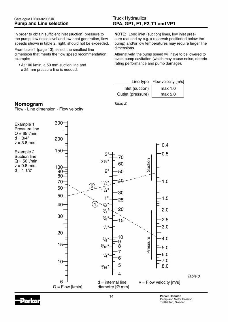
In order to obtain sufficient inlet (suction) pressure to the pump, low noise level and low heat generation, flow speeds shown in table 2, right, should not be exceeded.
From table 1 (page 13), select the smallest line dimension that meets the flow speed recommendation; example:
•At100l/min,a50mmsuctionlineand a 25 mm pressure line is needed.
Linetype Flowvelocity[m/s]
Inlet (suction) max 1.0 Outlet (pressure) max 5.0
Table 2.
NOTE: Longinlet(suction)lines,lowinletpres-sure (caused by e.g. a reservoir positioned below the pump) and/or low temperatures may require larger line dimensions.
Alternatively, the pump speed will have to be lowered to avoid pump cavitation (which may cause noise, deterio-rating performance and pump damage).
Example 1 Pressure lineQ=65l/mind=3/4"v=3.8m/s
Example 2Suction lineQ=50l/minv=0.8m/sd=11/2"
NomogramFlow-Linedimension-Flowvelocity
0.4
0.5
1.0
1.5
2.0
2.5
3.0
4.0
5.06.07.08.0
3"
2½"”
2"
70
50
60
40
30
25
20
15
1"
1 / "1 4
1/ "4
1 / "1 2
1/ "2
7/ "83/ "4
5/ "8
3/ "8
5/ "16
3/ "16
4
5
678910
300
200
150
10090807060
50
40
30
6
10
20
15
1
2
Q=Flow[l/min]d=internallinediametre[Ømm]
v=Flowvelocity[m/s]
Suc
tion
Pre
ssur
e
Table 3.
Truck HydraulicsGPA, GP1, F1, F2, T1 and VP1Pump and Line selection

15 Parker HannifinPump and Motor DivisionTrollhättan, Sweden
Catalogue HY30-8200/UK
2
3
Truck HydraulicsGPA and GP1 Pumps - Fixed Displacement
GPA and GP1 Pumps
Contents
Contents Page Chapter
PumpandLineselection ..............................................................................11 ................. 2
Specifications ...............................................................................................16
Installation Dimensions ............................................................................17-19
Ordering Information.....................................................................................20
Ordering code ...............................................................................................20
Suction fittings ..............................................................................................50 ............... 10
Installation and start up ................................................................................71 ............... 13

16 Parker HannifinPump and Motor DivisionTrollhättan, Sweden
Catalogue HY30-8200/UK Truck HydraulicsGPA and GP1 Pumps - Fixed DisplacementTechnical Information
Series GP1 (cast iron body; 3- and 4-bolt)
Frame size 016 019 023 029 036 041 046 050 060 070 080 100
Displacement[cm3/rev] 16 19 23 29 36 41 46 50 60 70 80 100 Max continuous pressure[bar] 270 260 250 240 230 210 200 300 280 240 200 170 Max intermittent pressure[bar] 300 300 300 290 270 260 250 310 290 250 210 180 Max peak pressure[bar] 300 300 300 290 270 260 250 320 300 260 220 190 Speed[rpm](atmaxcon- tinuous pressure) min 500 500 max 2000 2000 1800 1700 1600 1400 Weight[kg] 6.0 6.3 6.7 7.1 7.5 7.8 8.1 12.5 13.0 13.5 14.0 15.0
Series GPA (aluminum body; 3- and 4-bolt)
Frame size 008 012 016 019 Displacement[cm3/rev] 8 12 16 19 Max continuous pressure[bar] 250 250 250 230 Max intermittent pressure[bar] 270 270 270 250 Max peak pressure[bar] 290 290 290 270 Speed[rpm](atmaxcon- tinuous pressure) min 500 500 max 2000 2000 Weight[kg] 4.6 4.8 5.1 5.3
GPA and GP1Specifications

17 Parker HannifinPump and Motor DivisionTrollhättan, Sweden
Catalogue HY30-8200/UK
E142
GPA_008_019_3_ny5.aiLeif A./06-11-26
B
A 73
100
50
16
113Ø52
Ø120Ø11 (x3)
GPA_008_019_4_ny5.aiLeif A./06-11-26
C/186
B55
9 1238
108
80
A 7
8016 120
Ø13 (x4)
100
50
100
80
60
40
20
0 0 100 200 300
50
40
30
20
10
0 0 1000 2000
Torque_flow_GPA_ny5.aiLeif A./06-11-26
16
12
8
16
12
8
3
Truck HydraulicsGPA and GP1 Pumps - Fixed DisplacementInstallation Dimensions
Frame size 008 012 016 019
Dim. “A” 117 123 129 133 Dim. “B” 69 72 75 77
GPA-008/-012/-016/-019 4-bolt
GPA-008/-012/-016/-019 3-bolt
Frame size 008 012 016 019
Dim. “A” 147 153 159 163 Dim. “B” 99 102 105 107
Diagrams reflect theoretical values Direction of rotation: Bi-directionalInput pressure: 0.7 to 3.0 bar (absolute)
Fluid temperature: -25 °C to +80 °C Recommendedviscosity: 12to100mm2/s (cSt) Max viscocity: 750 mm2/s (cSt)
Spline B6x21x25 ISO 14 / DIN 5462
BSP 1/2" (14 deep; shown plugged)
BSP 1/2" both sides (14 deep)
Spline B8x32x36 ISO 14 / DIN 5462
BSP 1/2" (14 deep; shown plugged)
BSP 1/2" both sides (14 deep)
78.5
38.4
78.5
Torque[Nm]
Pressure[bar]
19 cm3/rev
Flow[l/min]
19 cm3/rev
Speed[rpm]

18 Parker HannifinPump and Motor DivisionTrollhättan, Sweden
Catalogue HY30-8200/UK
C/220
B
A
123
5
19
57
114 123Ø56
Ø72
84
Ø11 (x3)
108
78
GP1_016_046_3_ny5.aiLeif A./06-11-18
GP1_016_046_4_ny5.aiLeif A./06-11-25
19
57
114 129
78
Ø80
B 55
129
A 5
106
80
108
Ø13 (x4)
200
160
120
80
40
0 0 100 200 300
100
80
60
40
20
0 0 1000 2000
Torque_flow_GP1_016_046_ny5.aiLeif A./06-11-17
41
29
231916
36
1916
36 41
23
29
Truck HydraulicsGPA and GP1 Pumps - Fixed DisplacementInstallation Dimensions
GP1-016/-019/-023/-029/-036/-041/-046 4-bolt
GP1-016/-019/-023/-029/-036/-041/-046 3-bolt
Frame size 016 019 023 029 036 041 046
Dim. “A” 156 160 166 171 181 188 196 Dim. “B” 104 108 102 109 109 115 119
Frame size 016 019 023 029 036 041 046
Dim. “A” 121 125 131 136 146 153 161 Dim. “B” 69 73 67 74 74 80 84
Diagrams reflect theoretical values Direction of rotation: Bi-directional Input pressure: 0.7 to 3.0 bar (absolute)
Fluid temperature: -25 °C to +80 °C Recommendedviscosity: 12to100mm2/s (cSt) Max viscocity: 750 mm2/s (cSt)
Spline B8x32x36 ISO 14 / DIN 5462
Spline B6x21x25 ISO 14 / DIN 5462
BSP 3/4" (16 deep;
shown plugged)
BSP 3/4" both sides (16 deep)
BSP 3/4" both sides (16 deep)
BSP 3/4" (16 deep;
shown plugged)
53.5
53.5
46 cm3/rev 46 cm3/rev
Torque[Nm]
Pressure[bar]
Flow[l/min]
Speed[rpm]

19 Parker HannifinPump and Motor DivisionTrollhättan, Sweden
Catalogue HY30-8200/UK
GP1_050_100_4_ny5.aiLeif A./06-11-26
B 55
78 129
A 5
25146
73
152Ø80
108
80
135
Ø13 (x4)
400
300
200
100
0
0 100 200 300
200
150
100
50
0 0 1000 2000
70 60
5080
50
80
6070
Torque_flow_050_100_ny5.aiLeif A./06-11-26
3
Truck HydraulicsGPA and GP1 Pumps - Fixed DisplacementInstallation Dimensions
GP1-050/-060/-070/-080/-100 4-bolt
Frame size 050 060 070 080 100
Dim. “A” 167 174 180 187 200 Dim. “B” 97 104 101 107 111
Diagrams reflect theoretical values Direction of rotation: Bi-directionalInput pressure: 0.7 to 3.0 bar (absolute)
Fluid temperature: -25 °C to +80 °C Recommendedviscosity: 12to100mm2/s (cSt) Max viscocity: 750 mm2/s (cSt)
Spline B8x32x36 ISO 14 / DIN 5462
BSP 1¼" (shown plugged)
BSP 1¼" both sides
100 cm3/rev100 cm3/rev
Torque[Nm]
Pressure[bar]
Flow[l/min]
Speed[rpm]

20 Parker HannifinPump and Motor DivisionTrollhättan, Sweden
Catalogue HY30-8200/UK Truck HydraulicsGPA and GP1 Pumps - Fixed DisplacementOrdering Information
Ordering codeExample: GPA- 008 - 3
A Aluminium body1 Cast iron body
Frame size008, 012, 016, 019, 023, 029, 036, 041, 046, 050, 060, 070, 080 or 100
3 3 bolt flange4 4 bolt flange
Standard versionsAluminium 3 bolt
Designation Ordering no.
GPA-008-3 334 9113 921
GPA-012-3 334 9113 922
GPA-016-3 334 9113 923
GPA-019-3 334 9113 924
Aluminium 4 bolt
Designation Ordering no.
GPA-008-4 334 9113 911
GPA-012-4 334 9113 912
GPA-016-4 334 9113 913
GPA-019-4 334 9113 914
Cast iron 3 bolt
Designation Ordering no.
GP1-016-3 702 9113 921
GP1-019-3 702 9113 922
GP1-023-3 702 9113 923
GP1-029-3 702 9113 924
GP1-036-3 702 9113 925
GP1-041-3 702 9113 926
GP1-046-3 702 9113 927
Cast iron 4 bolt
Designation Ordering no.
GP1-016-4 702 9113 911
GP1-019-4 702 9113 912
GP1-023-4 702 9113 913
GP1-029-4 702 9113 914
GP1-036-4 702 9113 915
GP1-041-4 702 9113 916
GP1-046-4 702 9113 917
GP1-050-4 704 9113 911
GP1-060-4 704 9113 912
GP1-070-4 704 9113 913
GP1-080-4 704 9113 914
GP1-100-4 704 9113 915
NOTE: The pump does not include a suction fitting; it must be ordered separately. See chapter 10.

21 Parker HannifinPump and Motor DivisionTrollhättan, Sweden
Catalogue HY30-8200/UK
3
4
Truck HydraulicsF1 Pump - Fixed Displacement
F1 PumpF1-ISO
Contents
Contents Page Chapter
PumpandLineselection ..............................................................................11 ................. 2
F1-25 to -101, ISO ........................................................................................22
Specifications and pump cross section ........................................................22
Installation Dimensions, F1-25, -41, -51 and -61 ..........................................23
Ordering code and standard versions ..........................................................23
Installation Dimensions, F1-81 and -101 ......................................................24
Port size and standard versions ...................................................................24
F1-12 ISO with BSP port treads ...................................................................25
Specifications and pump cross section ........................................................25
Installation Dimensions, F1-12 with BSP port treads ...................................26
Ordering code and standard versions ..........................................................26
Installation Dimensions, F1-25, to -101, all ports are BSP .....................27-28
Ordering code and standard versions ..........................................................27
Suction fittings ..............................................................................................50 ............... 10
Installation and start up ................................................................................71 ............... 13

22 Parker HannifinPump and Motor DivisionTrollhättan, Sweden
Catalogue HY30-8200/UK
1 2 3 4 5 6 7 8 9
F1_stor_section_06-11-28.aiLeif A.
Truck HydraulicsF1 Pump - Fixed Displacement
F1 frame size 25 41 51 61 81 101 Displacement[cm3/rev] 25.6 40.9 51.1 59.5 81.6 102.9
Max flow 1)[l/min] at 350 bar 67 98 112 131 1633) 1853)
at 400 bar 56 86 97 113 143 160
Max operating pressure[bar] continuous 350 350 intermittent 400 400
Shaft speed[rpm] - short circuited pump (low press.) 2700 2700 2700 2700 2300 2300 - max speed at 350 bar2) 2600 2400 2200 2200 2000 3) 18003)
at 400 bar2) 2200 2100 1900 1900 1750 1550 3)
Torque1)[Nm] at 350 bar 142 227 284 331 453 572 at 400 bar 163 260 324 378 518 653
Input power[kW] - continuous 31 46 52 61 76 86 - intermittent 4) 39 57 66 76 95 108
Weight[kg] 8.5 8.5 8.5 8.5 12.5 12.5 1) Theoretical values 2) Valid at an inlet pressure of 1.0 bar (abs.) when operating on mineral oil at a viscosity of 30 mm 2/s (cSt). 3) Valid with 21/2" inlet (suction) line. With2"suctionline: F1-81–max1400rpm(Q ≈120 l/min); F1-101–max1000rpm(Q≈120 l/min). 4) Max 6 seconds in any one minute.
NOTE: For noise level information, contact Parker Hannifin
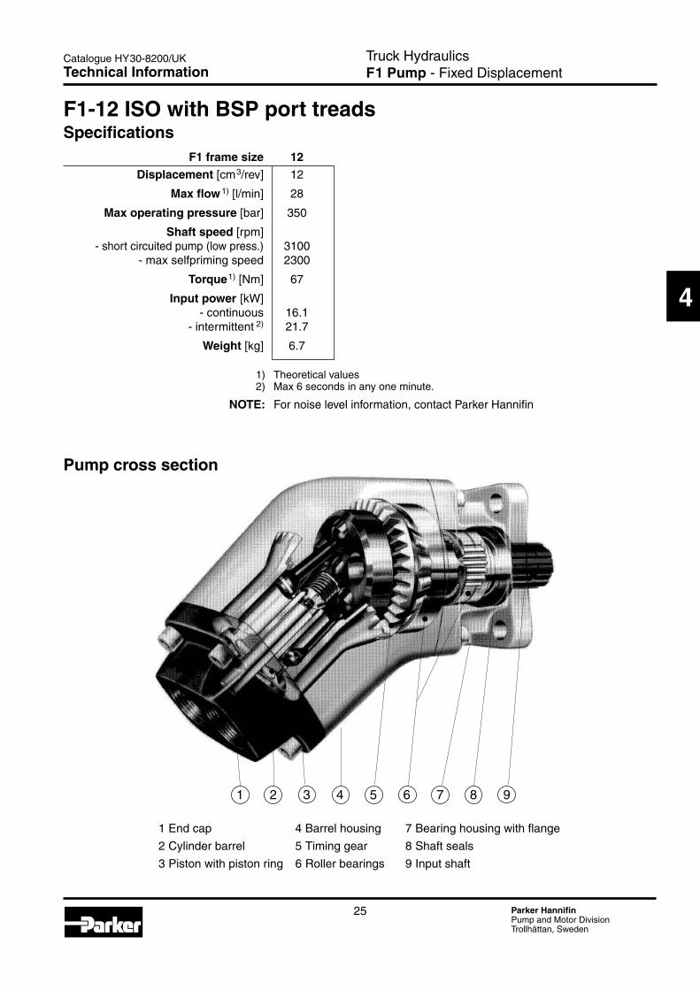
Specifications
1. Input shaft 4. Housing 7. Piston with piston ring2. Bearings 5. Timing gear 8. Cylinder barrel3. Shaft seals 6. Barrel support 9. End cap
Pump cross section
F1-25 to -101, ISO
Technical Information

23 Parker HannifinPump and Motor DivisionTrollhättan, Sweden
Catalogue HY30-8200/UK
F1_61_install_ny2.epsLeif A./06-08-07
ROTATIO
N
2226
22 26
M12x24
108
98104
80
Ø13 (x4)109
Spline shaft B8x32x36(ISO 14/DIN 5462)
7
7312
55
206
85
169
131
96
32
4
Truck HydraulicsF1 Pump - Fixed Displacement
Ordering codeExample: F1- 81 - RF1 frame size25, 41, 51, 61, 81 or 101
Shaft rotationR RighthandL Lefthand
Standard versions Designation Ordering no.
F1-25-R 3781024 -L 3781025
F1-41-R 3781040 -L 3781041
F1-51-R 3781050 -L 3781051
F1-61-R 3781060 -L 3781061 NOTE: The pump does not include a
suction fitting; it must be ordered separately. See chapter 10.
F1-25, -41, -51 and -61
Installation Dimensions
Suction port
Pressure port
Left hand rotation
Right hand rotation
Pressure port Suction port
Approx.center of gravity
27.8
Ø34.9
Ø80(+0/-0.013)
1.85 +0.3/-0
167.5 163.5
NOTE! The suction port fitting must be ordered separately
56.5

24 Parker HannifinPump and Motor DivisionTrollhättan, Sweden
Catalogue HY30-8200/UK
F1_81_install_ny3.epsLeif A./06-08-07
98114
80
Ø13 (x4)110
2528
25 28
M12x24
118
217 213
R ROTA
TION L
Al-Si10Mg
12
55
259
220
7
112
Spline B8x32x36(ISO 14/DIN 5462)
144
108
63
119
29
Suction port
Pressure port
Left hand rotation
Right hand rotation
Pressure port Suction port
NOTE! The suction port fitting must be ordered separately
1.85 +0.3/-0
Ø80(+0/-0.013)
Ø34.9
27.8
Approx.center of gravity
Truck HydraulicsF1 Pump - Fixed Displacement
Port size F1 frame size Pressure port 1)
-25 3/4" -41 3/4" -51 3/4" -61 3/4" -81 1" -101 1"
1) BSP thread (fitting not included)
Standard versions Designation Ordering no.
F1-81-R 3781080 -L 3781081
F1-101-R 3781100 -L 3781101
NOTE: The pump does not include a suction fitting; it must be ordered separately. See chapter 10.
F1-81 and -101
Installation Dimensions
25 Parker HannifinPump and Motor DivisionTrollhättan, Sweden
Catalogue HY30-8200/UK
1 2 3 4 5 6 7 8 9
4
1 End cap 4 Barrel housing 7 Bearing housing with flange
2 Cylinder barrel 5 Timing gear 8 Shaft seals
3Pistonwithpistonring 6Rollerbearings 9Inputshaft
F1-12 ISO with BSP port treads
F1 frame size 12 Displacement[cm3/rev] 12
Max flow 1)[l/min] 28
Max operating pressure[bar] 350
Shaft speed[rpm] - short circuited pump (low press.) 3100 - max selfpriming speed 2300
Torque1)[Nm] 67
Input power[kW] - continuous 16.1 - intermittent 2) 21.7
Weight[kg] 6.7
1) Theoretical values 2) Max 6 seconds in any one minute.
NOTE: For noise level information, contact Parker Hannifin
Specifications
Pump cross section
Truck HydraulicsF1 Pump - Fixed DisplacementTechnical Information

26 Parker HannifinPump and Motor DivisionTrollhättan, Sweden
Catalogue HY30-8200/UK
F1_12_install_UK.epsLeif A./03-06-13
Ø13 (x4)
106
98104
80
144
73 53
48
114
206
191
12
40°
10415
55
106Spline B8x32x36(ISO 14/DIN 5462)
ROTATION
89
10
Ordering codeExample: F1- 12 - R
F1 frame size 12
Shaft rotationR RighthandL Lefthand
Standard versions Designation Ordering no.
F1-12-R 3782212 -L 3782211
NOTE: The pump does not include a suction fitting; it must be ordered separately. See chapter 10.
F1-12 with BSP port treads
Pressure portBSP 1/2"
Suction portBSP 3/4"
M12x24 (thread)
8.5
Ø34.9
27.8
1.85 +0.3/-0
Truck HydraulicsF1 Pump - Fixed Displacement
Ø80(+0/-0.013)
Approx.center of gravity
Installation Dimensions

27 Parker HannifinPump and Motor DivisionTrollhättan, Sweden
Catalogue HY30-8200/UK
ROTATIO
N
Ø13 (x4)
98104
80
109
131
32 22 26
2226
Spline B8x32x36 (ISO 14/DIN 5462)
7
73
12
55
206
85
M12x24
108
F1_61_threads_ny.epsLeif A./06-09-25
4
NOTE: The pump does not include a suction fitting; it must be ordered separately. See chapter 10.
F1-25, -41, -51 and -61 with BSP port treads
Truck HydraulicsF1 Pump - Fixed Displacement
Port size (all ports are BSP) F1 frame size Pressure port Suction port
-25 3/4" 1" -41 3/4" 1" -51 3/4" 1" -61 3/4" 1"
Ordering codeExample: F1- 61 - RB
F1 frame size 25, 41, 51, 61, 81 or 101
Shaft rotation/port threads RB Righthand/BSP LB Lefthand/BSP
Standard versions Designation Ordering no.
F1-25-RB 3784024 -LB 3784025 F1-41-RB 3784040 -LB 3784041 F1-51-RB 3784050 -LB 3784051 F1-61-RB 3784060 -LB 3784061
Pressure port
Suction port
Suction port
Pressure port
Left hand rotation
Right hand rotation
Approx. center of gravity
56.5
27.8
167.5
1.85 +0.3/-0 Ø34.9
Ø80(+0/-0.013)
163.5
Installation Dimensions

28 Parker HannifinPump and Motor DivisionTrollhättan, Sweden
Catalogue HY30-8200/UK
R ROTATIO
NL
Al-Si10Mg
63144
29
98114
80
Ø13 (x4)110
25 28
2528
F1_81_threads_ny.epsLeif A./06-09-25
12
55
259
7
112
Spline B8x32x36 (ISO 14/DIN 5462)
119
M12x24
118
217 213
Port size (all ports are BSP) F1 frame size Pressure port Suction port
-81 1" 11/4" -101 1" 11/4"
Ordering codeExample: F1- 81 - RB
F1 frame size 25, 41, 51, 61, 81 or 101
Shaft rotation/port threads RB Righthand/BSP LB Lefthand/BSP
F1-81 and -101 with BSP port treads
Standard versions Designation Ordering no. F1-81-RB 3784080 -LB 3784081 F1-101-RB 3784100 -LB 3784101
Truck HydraulicsF1 Pump - Fixed Displacement
Ø34.9
Ø80(+0/-0.013)
27.8
1.85 +0.3/-0
Pressure port
Suction port
Suction port
Pressure port
Left hand rotation
Right hand rotation
Approx. center of gravity
Installation Dimensions
NOTE: The pump does not include a suction fitting; it must be ordered separately. See chapter 10.

29 Parker HannifinPump and Motor DivisionTrollhättan, Sweden
Catalogue HY30-8200/UK
4
F1 PumpF1-SAE
Truck HydraulicsF1 Pump - Fixed DisplacementIndex
Contents Page Chapter
PumpandLineselection ..............................................................................11 ................. 2
Specifications ...............................................................................................30
Pump cross section ......................................................................................30
Installation dimensions, F1-25, -41, -51 and -61 (SAE) ................................31
Ordering code (SAE) ....................................................................................31
Port size ........................................................................................................31
Suction fittings ..............................................................................................50 ............... 10
Installation and start up ................................................................................71 ............... 13

30 Parker HannifinPump and Motor DivisionTrollhättan, Sweden
Catalogue HY30-8200/UK
1 2 3 4 5 6 7 8 9
F1_61_SAE_cross_ny.epsLeif A./04-07-06
1. Input shaft
2. Bearings
3. Shaft seal
4. Housing
5. Timing gear
6. Barrel support
7. Piston with piston ring
8. Cylinder barrel
9. End cap
Pump cross section
NOTE: For noise level information, contact Parker Hannifin.
Specifications
Truck HydraulicsF1 Pump - Fixed Displacement
F1 frame size 25 41 51 61
Displacement[cm3/rev] 25.6 40.9 51.1 59.5 [cu in/rev] 1.56 2.50 3.12 3.63
Max flow 1) at350bar[l/min] 67 98 112 131 at 5000 psi [gpm] 17.7 25.9 29.6 34.6 at400bar[l/min] 56 86 97 113 at 5000 psi [gpm] 14.8 22.7 25.6 29.8
Max operating pressure continuous[bar]/ [psi] 350/5000 intermittent[bar]/ [psi] 400/5800
Shaft speed[rpm] - short circuited pump (low press.) 2700 2700 2700 2700 - max speed at 350 bar2)/5000 psi 2) 2600 2400 2200 2200 at 400 bar2)/5800 psi 2) 2200 2100 1900 1900
Torque1) at350bar[Nm] 142 227 284 331 at 5000 psi [lbf ft] 105 168 210 244 at400bar[Nm] 163 260 324 378 at 5800 psi [lbf ft] 120 192 239 279
Input power -continuous[kW] 31 46 52 61 [hp] 42 62 70 82 -intermittent [kW] 3) 39 57 66 76 [hp] 3) 52 76 88 102 Weight[kg] 8.5 8.5 8.5 8.5 [lbs] 18.7 18.7 18.7 18.7
1) Theoretical values 2) Valid at an inlet pressure of 1.0 bar/15 psi (abs.) when operating on mineral oil at a viscosity of 30 mm 2/s (cSt)/150 SUS. 3) Max 6 seconds in any one minute.
Technical Information

31 Parker HannifinPump and Motor DivisionTrollhättan, Sweden
Catalogue HY30-8200/UK
F1_SAE_ny5.epsLeif A./06-08-07
R ROTA
TION L
Al-Si10Mg
M8
186
8
33
12
163
22 26
26 22
118
118
Spline shaft S (SAE J744b) 22-4, 13T, 16/32 DP;
206
85
167
130
98
32
56 4
Port size F1 frame size Pressure port 1)
-25 11/16"-12 UN -41 11/16"-12 UN -51 11/16"-12 UN -61 11/16"-12 UN
1) BSP-to-SAE adapter (included).
Ordering code (SAE)
Example: F1- 61 - R U - S V - SF1 frame size25, 41, 51 or 61
Shaft rotationR RighthandL Lefthand
Standard SAE versions Designation Ordering no.
F1-25-R 3781424 -L 3781425
F1-41-R 3781440 -L 3781441
F1-51-R 3781450 -L 3781451
F1-61-R 3781460 -L 3781461
Installation dimensions, F1-25, -41, -51 and -61 (SAE)Dimensions in mm [inches]
Truck HydraulicsF1 Pump - Fixed Displacement
NOTE: The pump does not include a suction fitting; it must be ordered separately. See chapter 10.
Shaft endS SAE spline "B" spline
Shaft sealV FPM
Mounting flangeS SAE "B"
Main portU SAE O-ring, UN threads
[5.00 dia.]
The suction port adpter must be ordered separately
[8.11]
[6.57]
41.5[1.63]
Suction port
Right hand rotation
Suction port
Approx.center of gravity
pressure port adapter (included);tread: 11/16"-12 UN
Left hand rotation
89.8[3.54]
[4.65]
Ø14.3[0.56] (x4)[4.65]
[2.22][5.13]
[3.86]
[1.26]pressure port
adapter (included);tread: 11/16"-12 UN
[7.32] [6.43]
[1.02] [0.86]
[0.86] [1.02]
[0.47]
[1.30]
14.5[0.57]
[0.32]
9.5[0.37]
Ø21.6[0.850]Ø101.60(+0/-0.05)[4.000 (+0/-0.002)]
[3.35]
Flange S(SAE J744, 'B'
Spline according toSAE J498b, class 1.
Installation Dimensions

32 Parker HannifinPump and Motor DivisionTrollhättan, Sweden
Catalogue HY30-8200/UK
F1 Motor
Truck HydraulicsF1 Motor - Fixed DisplacementIndex
Contents Page Chapter
PumpandLineselection ..............................................................................11 ................. 2
Specifications ...............................................................................................33
Ordering code ...............................................................................................33
Installation ....................................................................................................33
Port size ........................................................................................................33
Standard versions .........................................................................................33
Suction fittings ..............................................................................................50 ............... 10
Installation and start up ................................................................................71 ............... 13

33 Parker HannifinPump and Motor DivisionTrollhättan, Sweden
Catalogue HY30-8200/UK
F1_motor_ny5.epsLeif A./06-08-07
Pump and M
otor Division
Made in Sweden - www.parker.com
PART NO.
TYPE SER NO.
98
55
[104] 114
11080
[167]220
Ø13(x4)
[206] 259
[98] 113
[BSP 3/4"]BSP 1"
[BSP 3/4"] BSP 1"
M12x24
5
Truck HydraulicsF1 Motor - Fixed Displacement
Specifications Motor frame size F1- 25-M 41-M 51-M 61-M 81-M 101-M 121-M
Displacement[cm3/rev] 25.6 40.9 51.1 59.5 81.6 102.9 118,5 Max operating pressure[bar] - continuous 250 250 - intermittent 350 350 Max shaft speed[rpm] - continuous 2 300 2 000 1 800 1 700 1 500 1 400 1300 - intermittent 3 000 2 700 2 400 2 200 2 000 1 800 1700 Torque (theor.)[Nm] - at 200 bar 81 130 162 189 259 327 376 - at 350 bar 142 227 284 331 453 572 658 Max output power[kW] - continuous 20 27 31 34 41 48 51 - intermittent 26 37 41 44 54 62 67 Weight[kg] 8.5 8.5 8.5 8.5 12.5 12.5 12.5
Installation
dimensions
Port size F1 motor frame size Port size
F1-25/41/51/61 3/4" -81/101/121 1"
Standard versions Designation Ordering no.
F1-25-M 378 1724 -41-M 378 1740 -51-M 378 1750 -61-M 378 1760 -81-M 378 1780 -101-M 378 1800 -121-M 378 4120
Ordering codeExample: F1 - 81 - MF1 Motor frame size25, 41, 51, 61, 81, 101 or 121
Note ! Drain line must be mounted.Connection BSP 1/2".Maximum drain line pressure is 3 bar
NOTE: - Dimensions, in mm, are valid for all frame sizes, except those in brackets[]whicharevalidfor F1-25/-41/-51/-61-M only.
Port A
49.5
Ø80 (+0/-0.013)
Port B
Ø34.9
Spline B8x32x36 (ISO 14/DIN 5462)
Technical Information

34 Parker HannifinPump and Motor DivisionTrollhättan, Sweden
Catalogue HY30-8200/UK
F2 Twin-flow Pump
Truck HydraulicsF2 Twin-flow Pump - Fixed DisplacementIndex
Contents Page Chapter
PumpandLineselection ..............................................................................11 ................. 2
Specifications ...............................................................................................35
Installation Dimensions .................................................................................36
Ordering code ...............................................................................................36
Standard versions .........................................................................................36
Suction fittings ..............................................................................................50 ............... 10
Installation and start up ................................................................................71 ............... 13

35 Parker HannifinPump and Motor DivisionTrollhättan, Sweden
Catalogue HY30-8200/UK
6
Truck HydraulicsF2 Twin-flow Pump - Fixed Displacement
F2plus_end_caps_GB.epsLeif A./000203
F2 B
A
F2 A
B
Outher pressure port (A)
Inlet (suction) port
Inner pressure port (B)
Outher pressure port (A)
Inlet (suction) port
Inner pressure port (B)
End cap for right hand rotating pump
Frame size F2- 42/42 53/53 55/28 70/35 70/70
Displacement[cm3/rev] Port A 43 54 55 69 68 Port B 41 52 28 36 68
Max operating pressure[bar] continuous 350 350 350 350 300 intermittent 400 400 400 400 350
Max shaft speed[rpm] (unloaded pump; low pressure) 2550 2550 2550 2550 2550
Max selfpriming speed [rpm] Ports A1) 2) and B1)2) pressurised 1800 1800 1800 1800 1650 Port A2) unloaded, pressure in port B 2100 2100 2100 2100 2100
Input power[kW] Max intermittent3) 100 126 100 126 131 Max continuous 88 110 88 110 112
Weight[kg] 19 19 19 19 19
1) Valid with 21/2" inlet (suction) line; with 2" inlet line: 53/53 and 70/35 max 1 100 rpm 42/42 and 55/28 max 1400 rpm. (q≈120 l/min)
2) Measured at 1.0 bar abs. inlet pressure. Please note: A lower inlet pressure affects pump performance.
3) Max 6 seconds in any one minute.
‘Left hand’ and ‘right hand’ end caps
Specifications
End cap for left hand rotating pump
Flow vs. shaft speed (theoretical) Pumpspeed[rpm] 800 1000 1200 1400 1600 1800 1900 2000 2100
F2-53/53 flow [l/min] Port A 43 54 65 76 86 97 - - - Port B 42 52 62 73 83 94 99 104 109 Total (ports A + B) 85 106 127 149 169 191 - - - Note: 42/42 values is 80% of 53/53 values
70/70 values is 130% of 53/53 values F2-70/35 flow[l/min] Port A 55 69 83 97 110 124 - - - Port B 29 36 43 50 58 65 68 72 76 Total (ports A + B) 84 105 126 147 168 189 - - - Note: 55/28 values is 80% of 70/35 values
Shaft torque vs. pressure (theoretical) Pressure[bar] 150 200 250 300 350
F2-53/53 torque[Nm] Port A 129 171 214 257 300 Port B 124 165 206 248 289 Total (ports A + B) 253 336 420 505 589 Note: 42/42 values is 80% of 53/53 values
70/70 values is 130% of 53/53 values F2-70/35 torque[Nm] Port A 164 219 274 329 383 Port B 86 114 143 171 200 Total (ports A + B) 250 333 417 500 583 Note: 55/28 values is 80% of 70/35 values
Technical Information

36 Parker HannifinPump and Motor DivisionTrollhättan, Sweden
Catalogue HY30-8200/UK
F2plus_install_GB.epsLeif A./020115
80
277
12
27.855
1.85 +0.3/-0
8.5
127119
169
213
40°
243
262
15
109
109 74
M12x24
148
Ø33 +0/-0.1
Ø34.9
81
51
81
51
18
Spline B8x32x36(ISO 14/DIN 5462)
F2 B
B
Truck HydraulicsF2 Twin-flow Pump - Fixed Displacement
Example: F2 - 53/53 - L
Framesize[cm3/rev]42/4253/5355/2870/3570/70Direction of rotation L Lefthand R Righthand
NOTE:- Before start-up, tighten the inspection port plug to 70–100 Nm. - To change the direction of rotation, the end cap must be replaced.
Ordering code Standard versionsDesignation Ordering no.
F2-42/42-R 3784042 F2-42/42-L 3784043
F2-53/53-R 3781453 F2-53/53-L 3781454
F2-55/28-R 3784128 F2-55/28-L 3784129
F2-70/35-R 3781470 F2-70/35-L 3781471
F2-70/70-R 3784070 F2-70/70-L 3784071
NOTE: The pump does not include a suction fitting; it must be ordered separately. See chapter 10.
Right hand rotation
Left hand rotation
Inlet (suction) port
Outlet (pressure) port (BSP 3/4")
Ø80(+0/-0.013)
Approx.center of gravity
Installation Dimensions
37 Parker HannifinPump and Motor DivisionTrollhättan, Sweden
Catalogue HY30-8200/UK
6
7
Truck HydraulicsT1 Pump - Fixed Displacement
T1 Pump
Index
Contents Page Chapter
PumpandLineselection ..............................................................................11 ................. 2
Specifications ...............................................................................................38
Pump cross section ......................................................................................38
Installation Dimensions ............................................................................39-40
Ordering code ...............................................................................................39
Port size ........................................................................................................39
Suction fittings ..............................................................................................50 ............... 10
Installation and start up ................................................................................71 ............... 13

38 Parker HannifinPump and Motor DivisionTrollhättan, Sweden
Catalogue HY30-8200/UK
1 2 3 4 5 6 7 8 9
F1_stor_section_06-11-28.aiLeif A.
Truck HydraulicsT1 Pump - Fixed Displacement
T1 frame size 81 121
Displacement[cm3/rev] 81.5 118,5
Max flow 1)[l/min] 1633) 1903)
Max operating pressure[bar] continuous 250 250 intermittent 4) 350 350
Shaft speed[rpm] short circuited pump (low press.) 2300 2300 max speed 2) 2000 3) 16003)
Torque1)[Nm] at 200 bar 258 376 at 350 bar 453 658
Input power[kW] continuous 54 71 intermittent4) 67 89
Weight[kg] 8.5 12.5
Specifications
Pump cross section(T1-121 shown)
1) Theoretical values2) Valid at an inlet pressure of 1.0 bar (abs.) when operating on mineral oil at a viscosity of 30 mm 2/s (cSt).3) Valid with 21/2" inlet (suction) line. With 2" suction line: T1-81–max1400rpm(Q ≈120 l/min); T1-121–max950rpm(Q≈120 l/min).4) Max 6 seconds in any one minute.
NOTE: For noise level information, contact Parker Hannifin.
Technical Information
1. Input shaft 4. Housing 7. Piston with piston ring2. Bearings 5. Timing gear 8. Cylinder barrel3. Shaft seals 6. Barrel support 9. End cap

39 Parker HannifinPump and Motor DivisionTrollhättan, Sweden
Catalogue HY30-8200/UK
F1_61_install_ny2.epsLeif A./06-08-07
ROTATIO
N
2226
22 26
M12x24
108
98104
80
Ø13 (x4)109
Spline shaft B8x32x36(ISO 14/DIN 5462)
7
7312
55
206
85
169
131 96
32
7
Truck HydraulicsT1 Pump - Fixed Displacement
T1-81
Suction port
Suction port
Pressure port BSP 3/4"
Left hand rotation
Right hand rotation
Pressure portBSP3/4"
Approx.center of gravity
27.8
Ø34.9
Ø80(+0/-0.013)
1.85 +0.3/-0
167.5 163.5
56.5
Installation Dimensions
Port size T1 frame size Pressure port 1)
-81 3/4" -121 1"
1) BSP thread (fitting not included).
Standard versions Designation Ordering no.
T1-81-R 3782180 -L 3782181
T1-121-R 3782120 -L 3782121
Ordering codeExample: T1 - 81 - R
T1 frame size81 or 121
Shaft rotationR RighthandL Lefthand
NOTE: The pump does not include a suction fitting; it must be ordered separately. See chapter 10.

40 Parker HannifinPump and Motor DivisionTrollhättan, Sweden
Catalogue HY30-8200/UK
T1_121_install_ny3.epsLeif A-son./06-09-22
98114
80
Ø13 (x4)110
2528
25 28
M12x24118
217 213
R ROTA
TION L
Al-Si10Mg
12
55
259
220
7
112
Spline B8x32x36(ISO 14/DIN 5462)
144108
63
119
29
Truck HydraulicsT1 Pump - Fixed Displacement
T1-121
Left hand rotation
Right hand rotation
Pressure port BSP 1"
Pressure port BSP 1"
Suction port
Suction port
1.85 +0.3/-0
Ø80(+0/-0.013)
Ø34.9
27.8
Approx.center of gravity
Installation Dimensions

41 Parker HannifinPump and Motor DivisionTrollhättan, Sweden
Catalogue HY30-8200/UK
7
8
Truck Hydraulics VP1 Pump - Variable Displacement
VP1 Pump
Index
Contents Page Chapter
PumpandLineselection ..............................................................................11 ................. 2
Specifications ...............................................................................................42
VP1-045/-075 cross section .........................................................................42
Installation Dimensions, VP1-045 and -075 ..................................................43
LSvalveblockVP1-045/075 .........................................................................44
Through-shaft coupling VP1-045/075 ...........................................................44
VP1-095/-130 cross section .........................................................................45
LScontrol(forVP1-095/-130) ......................................................................45
Installation Dimensions, VP1-095/130 ..........................................................46
System Information .......................................................................................47
Ordering information .....................................................................................47
VP1 in load sensing systems and Systems comparison ..............................47
LSloadsensingcontrolfunctionandLScontroladjustments ......................48
Suction fittings ..............................................................................................50 ............... 10
Installation and start-up for VP1 ...................................................................75 ............... 13

42 Parker HannifinPump and Motor DivisionTrollhättan, Sweden
Catalogue HY30-8200/UK
VP1 cross sectionLeif A./020115
8 9 10 11 12 13 14 15 16 17 18 19 20 21
1 2 3 54 6 7
Truck Hydraulics VP1 Pump - Variable Displacement
VP1-045/-075 cross section 1. Inlet port 2. ‘Top’ purge plug 3. Returnspring 4. Control 5. Setting piston (one of two) 6. Swash plate 7. Bearing shell 8. End cover 9. Spline (for mounting an auxiliary pump)10. Bearing sleeve11. Hold-down plunger12. Valve plate13. Cylinder barrel14. Barrel housing15. ‘Bottom’ purge plug16. Piston with piston shoe17. Retainerplate18. Bearing housing19. Rollerbearing20. Shaft seals with carrier21. Input shaft
Frame size VP1–045 VP1–075 VP1-095 VP1-130
Max displacement[cm3/rev] 45 75 95 128
Max pressure[bar] continuous 350 350 400 400 intermittent 1) 400 400 420 420
Mass moment of inertia J[kgm2] 0,00606 0,00606 0,00681 0,00690
Selfpriming speed2)[rpm] 2" suction line, max 2200 1700 - - 21/2" suction line, max 2400 2100 1750 - 3" suction line, max - - 2200 1900
Max Speed unloaded[rpm] (in bypass mode, no flow) 3000 3000 3000 3000
Control type LS
Shaft end spline DIN 5462
Mounting flange ISO 7653-1985
Weight(withcontrol)[kg] 27
Specifications
1) Max 6 seconds in any one minute.
2) At an inlet pressure of 1.0 bar (abs.) with mineral oil at a viscosity of 30 mm 2/s (cSt).
Technical Information

43 Parker HannifinPump and Motor DivisionTrollhättan, Sweden
Catalogue HY30-8200/UK
VP1_inst_GB.epsLeif A./01-03-19
80
120 max 20 max 55
M12x24
SplineB8x32x36(ISO 14/DIN 5462)
15
132 max
107 max 73 min 46 min
115
71 max
43
43
56
LST
34
29
104
8
Truck Hydraulics VP1 Pump - Variable Displacement
VP1-045 and -075
IMPORTANTThe control is not drained through the pump case.An external line must be installed between the con-trol drain port 'T' and the reservoir.
73 max(R.H.rotation)
73 max(L.H.rotation)
‘Top’ purge plug
‘Bottom’ purge plug
Outlet (pressure) portBSP1"(L.H.rotation)
Control drain port‘T’ (BSP 1/4")
Loadsensingport‘LS’ (BSP 1/4")
Outlet gauge portBSP1/4"(L.H.rot’n)
Inlet (suction) port;BSP 1 1/4"
Outlet gauge portBSP1/4"(R.H.rot’n)
Outlet (pressure) portBSP1"(R.H.rotation)
Inlet gauge port; BSP 1/4"
Centre of gravity
256.5
NOTE: The pump does not include a suction fitting; it must be ordered separately. See chapter 10.
11.8
1.85
27.8
Ø34.9
Ø80(+0/-0.013)
Installation Dimensions

44 Parker HannifinPump and Motor DivisionTrollhättan, Sweden
Catalogue HY30-8200/UK
LS
T
LS_block_GB.epsLeif A./020115
A
A
Truck Hydraulics VP1 Pump - Variable DisplacementTechnical Information
Through-shaft coupling VP1-045/075The VP1 pump has a through-shaft which means that an additional pump, such as a fixed displacement F1, can be installed in tandem with the VP1 by means of an adaptor kit (fig. 3).
NOTE: The bending moment caused by the weight of a tandem assembly normally exceeds that allowed by the PTO. To prevent damage, the auxiliary pump should be supported by a bracket attached to the gearbox; it must not be fastened to the truck chassis. Likewise,whenthetandemassemblyis installed on a separate bracket and driven by a cardan shaft, the auxiliary pump should have a support attached to the pump bracket.
Fig. 3. Adaptor kit (P/N 379 7795) for tandem coupling.
IMPORTANTContact Parker Hannifin for additional information when considering tandem mounting a second VP1 pump.
Fig. 2. LS valve block.
LS valve block VP1-045/075Loadsensing
port (BSP 1/4")
Setting spring
Valve spool
Cross section Section A–A
Pressure relief cartridge
Topp view
Differential pressure (∆p)adjustment(1turn=5bar)
Bottom view
O-ring (x6)Signal pressure
limiteradjustment(1turn=55bar)
Dampening nozzle (L.H.rotatingpump)
(To setting piston 1)
(To setting piston 2)
Dampening nozzle (R.H.rotatingpump)
Control drain port (BSP 1/4")

45 Parker HannifinPump and Motor DivisionTrollhättan, Sweden
Catalogue HY30-8200/UK
VP1_095_cross_section_ny2.aiLeif A./07-03-14
1 2 3 4 5 6 7 8 9 10
11 12 13 14 15 16 17 18 19 20
Truck Hydraulics VP1 Pump - Variable Displacement
VP1_095_control_section.aiLeif A./07-03-14
VP1_095_control_ports_ny2.aiLeif A./07-03-09
LS
LS
T
T
LS control (for VP1-095/-130)
Loadsensingport (BSP 1/4")
3. Basic valve setting (factory set) DO NOT TOUCH!
LS control cross section.
VP1-095/-130 cross section 1. Shaft seal 2. Rollerbearing 3. ‘Upper’ purge plug 4. Bearing shell 5. Setting screw (pressure relief valve) 6. Setting bushing (standby pressure) 7. Control 8. Piston with piston shoe 9. ‘Upper’ setting piston (control pressure) 10. Needle bearing 11. Shaft 12. Drain hole, shaft seals13. ‘Lower’purgeplug 14. Bearing housing 15. Swash plate16. Retainerplate17. ‘Lower’settingpiston(pump pressure) 18. Cylinder barrel 19. Valve plate 20. Barrel housing
To be connected directly to the oil tank (BSP 1/4")
1. Signal pressure cut-off (1turn=140bar)
2. Counter nut, screw 1
4. Standby pressure setting, factory set at 25 bar; (1turn=17bar)
5. Counter nut, bushing 4
LS control ports.
Technical Information

46 Parker HannifinPump and Motor DivisionTrollhättan, Sweden
Catalogue HY30-8200/UK
45
80
130
40
101
A
A
12
44
55269
VP1_095_install.aiLeif A./07-03-13
104
156
36 30
2930
659
29
659
3630
30
Truck Hydraulics VP1 Pump - Variable Displacement
VP1-095/-130
IMPORTANT!The control is not drained through the pump case; an external drain line must be installed from control port T and, directly, to the oil tank.
Washer (coveringthe shaft seal
drain hole)
‘Upper’ purge plug; BSP 1/4"(not tightened when delivered)
Rotationarrow(R.H.rotationshown)
‘Lower’purgeplug;BSP1/4"
Suctionport
Suctionport
Pressure port(BSP 1")
2 x M12 depth 17to attach support device
2 x M12 depth 17to attach support device
Pressure port(BSP 1")
View A–ARight hand rotating pump
View A–ALeft hand rotating pump
M8, 19 deep (x4);on P.C. dia. 55
Drain port T (BSP 1/4")
LoadsensingportLS(BSP 1/4")
Gauge port M (BSP 1/4")(system pressure)
Spline B8x32x36(ISO 14/DIN 5462)
M12(24 deep)
Installation Dimensions
NOTE: The pump does not include a suction fitting; it must be ordered separately. See chapter 10.
8.5
1.85
28.8
46.5Ø80
(+0/-0.013)
46.5
142.597.5
Ø12.5(x4)
Centre of gravity
Ø34.9

47 Parker HannifinPump and Motor DivisionTrollhättan, Sweden
Catalogue HY30-8200/UK
8
Diagram_1 _2.aiLeif A./09-04-09
Truck Hydraulics VP1 Pump - Variable Displacement
VP1 in load sensing systemsWhen installed in a load sensing system, the VP1 supplies the correct amount of flow required by the various work functions currently engaged. This means that energy consumption and heat generation are minimised and much reduced in comparison with a fixed displacement pump used in the same system. Diagram 1 shows the required power (flow times pressure) in a constant flow system with a fixed displacement pump.
Diagram 2 shows the sharply reduced power requirement in a load sensing system with a vari-able displacement pump such as the VP1.In both cases the pump pressure is slightly higher thanwhatisrequiredbytheheaviestload(’Load2’) but the VP1, because of the much smaller flow being delivered, needs only the power indicated by theshadedarea’Loadpower’.In a constant flow system, on the other hand, excess fluid is shunted to tank and the correspon-ding power, ’Wasted power’ (shown in diagram 1), is a heat loss.
Systems comparison System Constantflow Load-sensing Pump Fixed displ. VP1 variable displ.
Pumpadjustments Pressure only Pressure and flow Load* Some influence Some influence Energy consumption High Low Heatgeneration High Low
* Simultaneous operation of loads with non-equal flows and pressures; refer to the above diagrams.
Pressure Corner power
pMax
pLoad
QLoad1-3 QMaxFlow
Wasted power
Loadpower
Load
1
Load
2
Load
3
Pressure Corner power
pMax
pLoad
QLoad1-3 QMaxFlow
Wasted power
Loadpower
Load
1
Load
2
Load
3
Diagram 1. Constant flow system with a fixed displacement pump.
Diagram 2. Constant flow system with a variable displacement pump (e.g. VP1).
Ordering informationExample: VP1 - 045 - L
Frame size
045, 075, 095 or 130Direction of rotationL LefthandR Righthand
NOTE:The VP1 is uni-directional.Consequently, the desired direc-tion of rotation must be stated when ordering.
Standard model numbersDesignation Ordering no.
VP1-045-R 3780334 VP1-045-L 3780335 VP1-075-R 3780336 VP1-075-L 3780337 VP1-095-R 3786000 VP1-095-L 3786001 VP1-130-R 3784500 VP1-130-L 3784501
System Information

48 Parker HannifinPump and Motor DivisionTrollhättan, Sweden
Catalogue HY30-8200/UK
T T
T PT P
A B
1
A B
1
Min
Max
LS PLS P2
4
3
57Min
Max
2
4
3
6
7
6
8
9
5
LS load sensing control functionRefertocorrespondinghydraulicschematicbelow.A selected 'opening' of the directional control valve spool corresponds to a certain flow to the work function. This flow, in turn, creates a pressure differential over the spool and, consequently, also a ∆p between the pump outletandtheLSport.When the differential pressure decreases (e.g. the direc-tional valve is ‘opened’ further) the ∆p also decreases andtheLSvalvespoolmovestotheleft.Thepressureto the setting pistons then decreases and the pump dis-placement increases.The increase in pump displacement stops when the ∆p finally reaches the setting (e.g. 25 bar) and the forces acting on the valve spool are equal. IfthereisnoLSsignalpressure(e.g.whenthedirec-tional valve is in the neutral, no-flow position) the pump only delivers sufficient flow to maintain the standby pres-sure as determined by the ∆p setting.
Truck Hydraulics VP1 Pump - Variable DisplacementSystem Information
LS control adjustmentsPressure limiterPump size Factory setting
[bar]Max pressure
intermittent [bar]VP1-045/075 350 400VP1- 095/130 350 420
LS load sensing valvePump size Factory setting
[bar]Min pressure
[bar]Max pressure
[bar]VP1-045/075 25 20 35VP1- 095/130 25 15 40
The factory setting, and the standard orifice sizes shown in the corresponding schematic below, will usually provide an acceptable directional valve characteristic as well as system stability.For additional information, contact Parker Hannifin.
Setting pistons
1. Directional, load sensing control valve
2.Loadsignalorifice(1.0mm;fixed)
3. Gauge port
4.Signalpressurelimiteradjustment
5. System pressure dampening nozzle (2.0 mm)
6.Returnlinenozzle(0.6mm)
7. Standby (∆p)pressureadjustment
8. System pressure dampening orifice (fixed)
9. Bleed-off nozzle (0.6 mm).
Hydraulic schematic for VP1-45/75 Hydraulic schematic for VP1-095/130
To work function To work function
Setting piston
1. Directional, load sensing control valve
2. Loadsignalorifice(0.8mm)
3. Gauge port
4. Signalpressurelimiteradjustment
5. Standby (∆p)pressureadjustment
6. System pressure dampening orifice (fixed)
7. Bleed-off nozzle (1.2 mm)

49 Parker HannifinPump and Motor DivisionTrollhättan, Sweden
Catalogue HY30-8200/UK
8
9
Truck HydraulicsBLA Boost units
BLAGeneral informationTheBLAboostunitsimplifiesthebuildingofclosedorsemi-closed hydrostatic transmissions.
Main features are:• Replacesconventionalchargepumpand
corresponding valves in many applications• Allowspumpspeedsabovenormalselfpriming
speed• Suitableforsystemflowratesto400l/min• Includesfilter• Simpleconstruction-nomoving/wearparts• Cost-effectiveinstallation• Smalltanksize• Helpsinbuildingalow-costhydrostatic
transmission.
Typical applications:• Fandrives• Propellerdrives• Generatordrives• Pumpdrives.
DescriptionIn a closed circuit hydrostatic transmission, a charge pump is normally included with the main pump, pro-viding make-up fluid which replaces pump and motor volumetric losses. It also maintains sufficient pump inlet pressure to avoid cavitation.TheBLAboostunitreplacesthechargepumpinmanyapplications, when the following conditions are met:- The max-to-min pump flow ratio does not exceed 2:1- System pressure changes gradually without frequent and pronounced pressure peaks- The line length between pump and boost unit is relatively short.TherearetwobasicsizesoftheBLAboostunit:- BLA4(to160l/minpumpflow)- BLA6(to400l/min).The main part of the unit is an aluminium housing with a built-innozzleandaninjector;refertothecrosssectionto the right. When fluid flows from the motor outlet port through the unit and to the pump inlet port, the increased fluid veloc-itybetweenthenozzleandinjectorcreatesalowpres-sure zone causing additional fluid to be drawn from tank into the main circuit. Also,pressureincreasesaftertheinjector,allowingthepump to be operated at speeds higher than the self-priming speed. The ’boost pressure’ increases with flow. The housing includes ports that should be connected to the pump and motor drain ports respectively. An additional bleed-off nozzle diverts approx. 10% of the main flow through the cartridge filter before being directed to the tank.
Oil coolingAn oil cooler is usually required in the hydraulic system, in order to remove the heat that is generated in the main circuit. A full-flow oil cooler should be installed in the return line between the motor and the boost unit.
BLA boost unit cross section.
1
4
3 5
6
72
BLA_install.epsLeif A./02-01-03
1. Pump2. Motor3. Boostunit(withinjector
and nozzle4. Filter cartridge
5. Pressure relief valve6. Full-flow filter (when
required7. Reservoir
Boost unit installation
For more information please see our technical catalogue BLA boost unit HY17-8224/UK
BLA_cross_section.epsLeif A./02-01-03
Injector From Nozzle tank
To pump
inlet
Frommotoroutlet
Bleed-offnozzleTo
filter
From filterto tank
General Information

50 Parker HannifinPump and Motor DivisionTrollhättan, Sweden
Catalogue HY30-8200/UK
Ordering no. A mm B mm C dia. mm (in.) 378 09781) 126 83 38 (11/2") 378 09792) 135 83 50 (2")
378 19803) 147 83 63 (21/2") 378 0976 135 83 45 378 86903) 185 83 75 (3")
Truck HydraulicsFittings
Ordering no. A mm B mm C dia. mm (in.) 378 06351) 0 85 38 (11/2") 378 06362) 17 136 50 (2") 378 06373) 25 145 63 (21/2") 378 35233) 32 174 75 (3")
Suction fittingsfor series F1, F2 and T1 pumps also VP1-095 and -130
Suctions fittings for VP1-045/075 see page 51.
’Straight’ suction fittings for F1, F2, T1, VP1-095/-130
Ordering no. A mm B mm C dia. mm (in.) 378 12341) 60 104 32 (11/4") 378 06331) 60 104 38 (11/2") 378 03642) 67 110 50 (2 ") 378 06343) 75 117 63 (21/2") 378 33673) 95 138 75 (3") 378 1062 67 110 40 378 0975 67 110 45 378 0965 67 110 48
45° suction fittings for F1, F2, T1, VP1-095/-130
90° suction fittings for F1, F2, T1, VP1-095/-130
Ordering no. A mm B mm C dia. mm (in.)
378 1867 165 73 50 (2 ")
145° suction fitting for F1, F2, T1, VP1-095
Suction_fittings_F1plus_GB.epsLeif A./020115
C
C
C
C
A
A
A
B
B
B
A
B
Suction fitting
Cap screw Hold-down clamp
O-ring‘Straight’ fitting
45° fitting
90° fitting
145° fitting
A ’suction fitting’ consists of a straight, 45°, 90° or 135° suction fitting, clamps,
cap screws and O-ring.
NOTE: A suction fitting must be ordered sepa- rately (not included with the pump). To choice the correct dimension of suction connection, see chapter 2.
Installation Dimensions
Spare partsAdditional Hold-down-clamp kit consists of: hold-down-clamp cap screw and O-ring Ordering no. 378 1321
Additional Hold-down-clamp kit for mounting on BPV Ordering no. 378 2439
19.5
19.5
19.5
19.5
1)RecommendedforframesizeF1-25. 2)RecommendedforframesizeF1-41,-51,-61,-81,-101. 3) (3 clamps and 3 screws)

51 Parker HannifinPump and Motor DivisionTrollhättan, Sweden
Catalogue HY30-8200/UK
10
Nipplar_ny.epsLeif A./05-01-21
13 C
ØA
ØB
ØB
ØA
44 13
C
Suitable suction adapters for F1 with BSP port treads
45° adapter Ordering no. A* B C
00509035016 1" 2" 18 00509035116 11/4" 2 " 18 00509021916 11/4" 21/2" 18
* BSP threads
90° adapter Ordering no. A* B C
00509034516 1" 2" 18 00509034616 11/4" 2" 18
* BSP threads
C2
C2
C2
C1
C1
C1
Fittings_install_GB.epsLeif A./020115
A
B
A
B
Pressure fitting
45°adjustable suction fitting
Fitting kits for VP1-045 and -075 pumps
Kits with 45° suction fitting Pump size Ordering no. C1 ØC2 A B
VP1-045/075 379 9563 BSP 3/4" 2" 71 154VP1-045/075* 379 9562 BSP 1" 21/2" 64 147
* Above 100 l/min
NOTE: A suction fitting must be ordered sepa- rately (not included with the pump). To choice the correct dimension of suction connection, see chapter 2.
Truck HydraulicsFittingsInstallation Dimensions

52 Parker HannifinPump and Motor DivisionTrollhättan, Sweden
Catalogue HY30-8200/UK Truck HydraulicsAuxiliary valves
Auxiliary ValvesBypass Valves and Unloading Valves forF1, F2, T1 and VP1 pumps
Index
Contents Page
BPV-F1 and BPV-T1 bypass valve .............................................................53
Technical Information ..............................................................................53
Ordering information and Drawings ........................................................53
BPV-F1 and BPV-T1 Bypass valve valve without manual override .........54
BPV-F1 Bypass valve with manual override ...........................................54
BPV-F2 bypass valve ..................................................................................55
Technical Information ..............................................................................55
Ordering information and Drawings ........................................................55
BPV-F2 Bypass valve without manual override ......................................56
BPV-F2 Bypass valve with manual override ...........................................57
BPV-F1, -T1 and F2 Accessories / Spare Parts ........................................58
BPV-L line mounted bypass valve ............................................................59
BPV-VP1 unloading valve ..........................................................................60

53 Parker HannifinPump and Motor DivisionTrollhättan, Sweden
Catalogue HY30-8200/UK
11
BPV_F1_schematic.epsLeif A./020114
’q’
Pilot operated check valve
Solenoid valve
Directional control valve (‘open centre’)
F1 pump Valve block Drain port (External line)
BPV-F1 and BPV-T1 bypass valve• Thebypassvalveismainlyutilisedinapplications
where the F1 pump is driven from the crank-shaft through a cardan shaft, or when it is installed on an engine PTO.
• TheBPVbypassvalveshouldbeengagedduring transportation when the pump is operating cons- tantly and the engine is running at max rpm; the hydraulic system is not sized for the large flow that would otherwise go through it.
• TheBPVvalvesubstantiallyreducestheenergy loss during transportation.
• Thevalveinstallsdirectlyontopofthepumpend capwithapressureport’banjo’fittingandaninlet port spacer bushing with two cap screws; refer to the illustration to the right.
• AstheBPVvalveissymmetrical,itcanbe’turned 180°’ to prevent interference with chassis compo- nents; it can be utilised for either left hand or right hand pumps.
• Thevalvefunctionmustonlybeactivatedor released (by means of the 24 VDC solenoid)
at no-load (below 20 bar) system pressure.
IMPORTANT INFORMATION- In order to prevent heat build-up in the pump
during transportation, it is important that at least 5 l/min comes out of the filter at ’q’ (refer to the schematic). This applies to an ’open center’ system when the valve is in the bypass mode (non-activated solenoid).
- Please note: a) If the flow at ’q’ is less than 5 l/min (caused e.g. by a high pressure drop in the main system) when the valve is in the bypass mode, or b) if the hydraulic system is of the ’closed center’ type, then an external drain line must be installed from the bypass valve drain port directly to tank as shown in the schematic; a drain kit is available (see next page).
Bypass valve schematic.
Truck HydraulicsAuxiliary valves
Pump pressure portPump suction port
Pressure connector
Valve body
O-ring (x2)
(F1 end cap)
Suction adapter
Hold-down clamp (x2)
O-ring (x3)
Spacer bushing
Technical Information
39 (39)
BSP 1"(BSP 3/4")
NoteThe bypass valve is available in two versions, one with and one without manual override. The solenoid cartridge with manual override can not be installed in valve blocks designed for solenoid cartridge without manual override and vice versa because of the solenoid cartridges different connection threads.
Ordering information and DrawingsSee next page.

54 Parker HannifinPump and Motor DivisionTrollhättan, Sweden
Catalogue HY30-8200/UK Truck HydraulicsAuxiliary valves
Ventilblock_09-02-05.aiLeif A.
105 (103)
110(109)
BPV-F1 and -T1 installation and cross section without manual override
NOTE: Dimensions are shown for BPV-F1-81 (those for BPV-F1-25 are in parenthesis)
NOTE: Dimensions are shown for BPV-F1-81 (those for BPV-F1-25 are in parenthesis)
IMPORTANT:Always tighten the pressure connector before tighten-ing the cap screws.Also, see table to the left.
IMPORTANT:Always tighten the pressure connector before tighten-ing the cap screws.Also, see table to the left.
Valve housing
Drain port (plugged); BSP 1/4"
Hold-down clamp (x2)
Cap screw (x2)
Valve housing
Drain port (plugged); BSP 1/4"
Hold-down clamp (x2)
Cap screw (x2)
Solenoid valve
Solenoid valve
Connector(included)
Connector(included)
BPV-F1 installation and cross section with manual override
Ventilblock_11-10-24.aiLeif A.
105 (103)
110(109)
Manual override
BPV-F1 Bypass valveWith manual override
Bypassvalve kits
Voltage Orderingnumber
For F1 size Torque1)
BPV-F1-25, 24 VDC 378 7461 F1-25, -41, -51 and -61
50 Nm
BPV-F1-81, 24 VDC 378 7462 F1-81 and -101
100 Nm
Drain fitting kit F1-025
378 1640 Contains a drain line fitting a bonded seal and nozzle.
Drain fitting kit other F1, F2
378 3039 Contains a drain line fit-ting and a bonded seal.
1) Torque pressure connector to:
Bypassvalve kits
Voltage Orderingnumber
For F1 and T1 size
Torque1)
BPV-F1-25 24 VDC 378 8803 F1-25 50 Nm
BPV-F1-41, BPV-T1-81
24 VDC 12 VDC
378 7201 378 7202
F1-41, -51, -61 and T1-81
50 Nm
BPV-F1-81, BPV-T1-121
24 VDC 12 VDC
378 7203 378 7204
F1-81, -101 and T1-121
100 Nm
Drain fitting kit F1-025
378 1640 Contains a drain line fitting a bonded seal and nozzle.
Drain fitting kit other F1, F2 and T1
378 3039 Contains a drain line fit-ting and a bonded seal.
1) Torque pressure connector to:
Bypass valve, type BPV-F1-25 and -81Max pressure, continuous 350 barintermittent 400 bar Solenoid voltage 24 VDCPower requirement 17 WOperating mode Activated solenoid:
Check valve closed
Bypass valve, type BPV-F1-25 to -101 and BPV-T1-81 and -121
Max pressure, continuous 350 barintermittent 400 bar Solenoid voltage (option) 24 VDC, (12 VDC)Power requirement 17 WOperating mode Activated solenoid:
Check valve closed
BPV-F1 and BPV-T1 Bypass valveWithout manual override
Ordering information and Drawings

55 Parker HannifinPump and Motor DivisionTrollhättan, Sweden
Catalogue HY30-8200/UK
BPV_F2plus_schem_GB.epsLeif A./000323
A
B
BPV-F2
F2-twin-flow pump
Solenoid valve (24 or 12 VDC)
Directional control valves (‘open centre’)
Pilot operated check valve
Separate drain line
Bypass valve circuit schematic (example).
BPV-F2 bypass valve• AnF2twinpumpfittedwithabypassvalvecanbe
utilised in applications where the pump is operating constantly i.e. when the pump is driven from the crank- shaft through a cardan shaft, or when it is installed on an engine-PTO. In addition, it can be used when, temporarily, one of the two circuits is not required; the power loss is thus reduced as the non-required flow is not forced through lines and ’open center’ valves.
• TheBPVbypassvalveshouldbeengagedduring transportation when the pump is operating cons- tantly and the engine is running at max rpm; the hydraulic system is not sized for the large flow that would otherwise go through it.
• TheBPVvalveconnectstheoutletandinletportsof the pump, and only a small oil flow goes through the system and to the reservoir.
• Thevalveisinstalleddirectlyontopofthepumpport surfacewith’banjo’fittingsandtwocapscrews(refer to the split view to the right).
• AstheBPVvalveissymmetricalitcanbe’turned180°’ so as not to interfere with chassis components.The valve can accommodate left hand as well as right hand rotating pumps.
• Thevalvecanonlybeengagedordisengaged( through the 24 or 12 VDC solenoid) at low system pressures (below 20 bar).
IMPORTANT INFORMATION- In order to secure a cooling flow through the system,
a separate drain line must be connected from the BPV-F2 drain line fitting (shown in the split view) directly to tank; refer also to the schematic.
- The pressure connectors must be tightened (to 50 Nm) before the suction fitting clamp screws are tightened.
Truck HydraulicsAuxiliary valvesTechnical Information
NoteThe bypass valve is available in two versions, one with and one without manual override. The solenoid cartridge with manual override can not be installed in valve blocks designed for solenoid cartridge without manual override and vice versa because of the solenoid cartridges different connection threads.
Ordering information and DrawingsSee next page.
11

56 Parker HannifinPump and Motor DivisionTrollhättan, Sweden
Catalogue HY30-8200/UK Truck HydraulicsAuxiliary valves
BPV_F2_split_09-02-05.aiLeif A.
O-ring (x4) 1)
1) The BPV-F2 valve kit contains parts designated ’1’ in the split view to the right.
2) A suction fitting kit (parts designated ’2’ in the split view) is not included with the F2 pump; it must be ordered separately (refer to chapter10)..
3) Torque pressure connector to:
Bypassvalve kits1)
Voltage Orderingnumber
For F2 size Torque3)
BPV-F2, 24 VDC12 VDC
378 7424378 7425
42/42, 53/53, 55/28, 70/35, 70/70
50 Nm
‘1’-BPV-F2 valve kit
Cap screw 1)
Pressure con- nector (x2) 1)
‘2’- Suction fitting kit
Suction fitting 2)
Hold-down clamp (x2) 1)
Drain line (not included) to be connected directly to tank
O-ring 2)
Drain line fitting1)
(BSP 1/4")
Bonded seal 1)
Valve blocksub-assy 1)
Solenoid valve (x2) 1); (connector included)
Plug with bonded seal1)
Spacer bushing 1)
O-ring (x2) 1)
Bypass valve split view without manual override (with F2 end cap).
NOTE: A suction fitting kit (parts designated ’2’ in the split view) is not included with the F2 pump; it must be ordered separately (refer to chapter10).
BPV-F2 Bypass valveWithout manual override
Ordering information and Drawings
Bypass valve, type BPV-F2Max pressure, continuous 350 barintermittent 400 bar Solenoid voltage (option) 24 VDC, (12 VDC)Power requirement 17 W (each solenoid)Operating mode Activated solenoid:
Check valve closed

57 Parker HannifinPump and Motor DivisionTrollhättan, Sweden
Catalogue HY30-8200/UK
11
Truck HydraulicsAuxiliary valves
1) The BPV-F2 valve kit contains parts designated ’1’ in the split view to the right.
2) A suction fitting kit (parts designated ’2’ in the split view) is not included with the F2 pump; it must be ordered separately (refer to chapter10)..
3) Torque pressure connector to:
Bypassvalve kits1)
Voltage Orderingnumber
For F2 size Torque3)
BPV-F2, 24 VDC 378 7463 42/42, 53/53, 55/28, 70/35, 70/70
50 Nm
BPV_F2_split_11-10-24.aiLeif A.
O-ring (x4) 1)Manual override
‘1’-BPV-F2 valve kit
Cap screw 1)
Pressure con- nector (x2) 1)
‘2’- Suction fitting kit
Suction fitting 2)
Hold-down clamp (x2) 1)
Drain line (not included) to be connected directly to tank
O-ring 2)
Drain line fitting1)
(BSP 1/4")
Bonded seal 1)
Valve blocksub-assy 1)
Solenoid valve (x2) 1); (connec-tor included)
Plug with bonded seal1)
Spacer bushing 1)
O-ring (x2) 1)
Bypass valve split view with manual override (with F2 end cap).
NOTE: A suction fitting kit (parts designated ’2’ in the split view) is not included with the F2 pump; it must be ordered separately (refer to chapter10).
BPV-F2 Bypass valveWith manual override
Ordering information and Drawings
Bypass valve, type BPV-F2Max pressure, continuous 350 barintermittent 400 bar Solenoid voltage 24 VDCPower requirement 17 W (each solenoid)Operating mode Activated solenoid:
Check valve closed

58 Parker HannifinPump and Motor DivisionTrollhättan, Sweden
Catalogue HY30-8200/UK Truck HydraulicsAuxiliary valvesTechnical Information
Solenoid
Cartridge valve assy
Inlet union screw
O-ring
Flange clamp 1)Part No Description Remarks
3781480 Inlet union screw F2 (all sizes)
3781082 Inlet union screw F1-25, -41, -51, -61
3781094 Inlet union screw F1-81, -101
3780641 O-ring kit For both F1 and F2 (all sizes)
3782439 Hold-down clamp Suction fitting 1)
For BPV F1 and F2
1) Hold-down clamp for suction fitting on bypass valve for F1, T1 and F2 (parts designated ’1’ in the split view).
Part No Description Remarks
3787496 Solenoid 24V Incl. new connector
3787497 Solenoid 12V Incl. new connector
3787494 Cartridge valve assy 24V
Without manual override
3787495 Cartridge valve assy 12V
Without manual override
3785948 Nut for cartridge valve
3787488 Male contact kit
Part No Description Remarks
3788663 Cartridge valve assy 24V
With manual override
BPV-F1, -T1 and F2 Accessories / Spare Parts
NoteThe bypass valve is available in two versions, one with and one without manual override. The solenoid cartridge with manual override can not be installed in valve blocks designed for solenoid cartridge without manual override and vice versa because of the solenoid cartridges different connection threads.
Screw 1)
O-ring 1)
Male contact kit
Nut

59 Parker HannifinPump and Motor DivisionTrollhättan, Sweden
Catalogue HY30-8200/UK
Unloading valve, type BPV-L
Maxoperatingpressure[bar] 350
Maxflow[l/min] 250
Solenoidvoltage[VDC] 24
Requiredpower[W] 17
Operating mode Activated solenoid: Check valve closed
Ordering number 378 1487
BPV-L line mounted bypass valve• TheunloadingvalveBPV-Lisutilisedinhydraulic
systems where the fixed displacement pump is en-gaged constantly and no flow is required, i.e. during transportation. The flow is directed through the un-loading valve which has a low pressure loss and less heat is being generated in the system.
• Whenthesolenoidisactivatedtheunloadingvalvecloses and the pump flow is directed to the directional control valve or other user.
Truck HydraulicsAuxiliary valves
BPV_L_schematic_GB.epsLeif A./020115
Unloading valve
Gauge port ‘G’
Directional control valve (‘open centre’)
Solenoid valve
Technical Information
100
6245
4510 10
100
BSP 1"(x2)
φ 9(x2)
50
'IN'
'UT'
BPV_L_install_09-02-05.aiLeif A.
Solenoid valve (24 VDC standard);connector included
Gauge port (BSP 1/4")
11
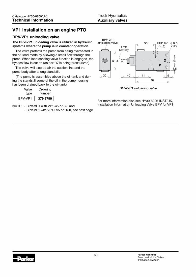
60 Parker HannifinPump and Motor DivisionTrollhättan, Sweden
Catalogue HY30-8200/UK
51.5 32
8.5
4192
9�4030
53 φ 6.5(x2)
T P
SX
BPV-VP1_unloading_valve.aiLeif A./09-04-15
4 mm hex key
BSP 1/4"(x3)
BPV-VP1 unloading valve
Truck HydraulicsAuxiliary valvesTechnical Information
BPV-VP1 unloading valve.
For more information also see HY30-8226-INST/UK, Installation Information Unloading Valve BPV for VP1
VP1 installation on an engine PTO
BPV-VP1 unloading valveThe BPV-VP1 unloading valve is utilized in hydraulic systems where the pump is in constant operation. The valve protects the pump from being overheated in the off-load mode by allowing a small flow through the pump. When load sensing valve function is engaged, the bypass flow is cut off (as port ‘X’ is being pressurized).
The valve will also de-air the suction line and the pump body after a long standstill.
(The pump is assembled above the oil-tank and dur-ing the standstill some of the oil in the pump housing has been drained back to the oil-tank)
Valve Ordering type number
BPV-VP1 379 8799
NOTE: - BPV-VP1 with VP1-45 or -75 and - BPV-VP1 with VP1-095 or -130, see next page.

61 Parker HannifinPump and Motor DivisionTrollhättan, Sweden
Catalogue HY30-8200/UK
BPV-VP1-045-075_schematic.aiLeif A./09-04-15
SX
TP
Loadsens-ing valve
Loadsensing(LS)line
VP1-045or -075pump
BPV-VP1 unloading
valve (5 bar)
Fittingwith orifice (included)
VP1-45-75_ports.aiLeif A./09-04-15
Port T (BSP 1/4") Must be connected directly to tank! Port LS (BSP 1/4")
Pressure port (BSP 1")
Suction port (BSP 1 1/4")
Port M (BSP 1/4")
BPV-VP1 installation schematic with VP1-45/ -75 pump.
VP1-45/ -75 end view (showing ports).
BVP-VP1 with VP1-45/75 pumps
NOTE: - Install the fitting (included) in port M and connect it, in turn, to port S of the unloading valve (see schematic). - An orifice is inclu- ded in the fitting.
VP1-095/-130 main ports (with fitting installation).
VP1-095/-130 control valve ports.
Truck HydraulicsAuxiliary valvesTechnical Information
BPV-VP1 with VP1-095/-130 pumps
VP1-095_ports.aiLeif A./09-04-15
Port M (BSP 1/4") Install fitting!
Pressure port (BSP 1")
Suction port
Left hand rotating pump
Right hand rotating pump
VP1-095_ports.aiLeif A./09-04-15
Port T (BSP 1/4");Must be connected directly to tank!
Port LS (BSP 1/4")
BPV-VP1-095_schematic.aiLeif A./09-04-15
SM
T
LS X
TP
VP1-095/-130 pump
Nipple with orifice
Loadsensingvalve
BPV-VP1 unloading valve (5 bar)
Loadsensing(LS)line
NOTE: - Install the fitting (included) in port M and connect it, in turn, to port S of the unloading valve (see schematic). - An orifice is inclu- ded in the fitting.
BPV-VP1 installation schematic with VP1-095/-130 pump.
11

62 Parker HannifinPump and Motor DivisionTrollhättan, Sweden
Catalogue HY30-8200/UK
AccessoriesAdapter kits and accessories for F1, F2, T1 and VP1 pumps
Truck HydraulicsAccessoriesIndex
Contents Page
PTO Air Valve Kits:
Air valve kit for Volvo PTO's ..........................................................................63
Universal PTO air valve kit ............................................................................63
PTO Adapter Kits:
PTO adapter kit for Scania ED 120 engines ................................................64
PTO adapter kit for Scania ED 160 engines ................................................65
PTOadapterkitforMercedesengines(R6) .................................................66
PTO adapter kit for Mercedes engines (V6, V8) ...........................................66
PTO adapter kit for MAN (D20, D26, D28) ...................................................66
Cardan shafts, pump couplings and mounting brackets ..............................67
Cardan shaft specifications ..........................................................................67
PTO flange adapters ....................................................................................67
Pump couplings ............................................................................................68
SB splitter boxes ...........................................................................................69
Recommendations ........................................................................................69
Installation information ..................................................................................69
Splitter box installation ..................................................................................70

63 Parker HannifinPump and Motor DivisionTrollhättan, Sweden
Catalogue HY30-8200/UK
PTO air valve kit Volvo Airvalvenominalvoltage[VDC] 24 Nominalcurrent[A] 0.4 Requiredpower[W] 9.6 Maxairpressure[bar] 10 Air hose size 1/4" Operating mode Activated solenoid: Air valve open and PTO engaged.
Ordering number, 378 1010 series FM and FH
• TheairvalvekitissuitableforoperatingaVolvoPTO on Series FM and FH truck chassis. All parts required to operate the PTO are included in the kit (as shown below).
• Theairvalvecanbecombinedwithotherairvalves on the chassis; this means a simple installation with a common air supply and a minimum of hoses.
• Allelectricalwiresarepre-installedonthechassis. The relay should be installed in socket K1-14 behind the dashboard cover.
• Function: The relay makes sure the PTO is being disengaged
as soon as the 'ignition key' is turned off. To re-engage the PTO, the operator has to put the
switch back to neutral, and then move it to the 'ON' position.
Air valve kit for Volvo PTO's.
Air valve kit for Volvo PTO's
Truck HydraulicsAccessories
PTO air valve kit Universal
Airvalvenominalvoltage[VDC] 24 Nominalcurrent[A] 0.4 Requiredpower[W] 9.6 Maxairpressure[bar] 10 Air hose size 1/4" Operating mode Activated solenoid: Air valve open and PTO engaged.
Ordering number 370 8779
• Thekitincludesallpartsrequiredformaneouvering the PTO.
• TheairvalvekitissuitableformostPTO'switha metric M12x1.5 air connection.
• Theairvalvecanbeinstalledwithotherairvalves on the chassis which means simple installation with
common air supply and a minimum of hoses.• Theairvalvecanbeconnectedtoelectricalwires
usually pre-installed on the chassis.
Universal PTO air valve kit
Technical Information
12

64 Parker HannifinPump and Motor DivisionTrollhättan, Sweden
Catalogue HY30-8200/UK
Scania_ED120_adapter_ny2.aiLeif A./06-11-15
Max.torque[Nm] 600 Gear ratio (engine :pump) 1 : 1.19 Pumprotation Righthand(clockwise)
PTO adapter kit Ordering number
ED-90/120-F1/F2, bearing supported (37°) 378 3080 ED-90/120-VP1, bearing supported (22°) 378 3081
PTO adapter kit for Scania ED 120 engines The adapter also fit ED90, motor DC9-11, from September 2004 and later.• Withtheadapterkit,ahydraulicpump(e.g.F1or
VP1) that meets the ISO standard can be installed on the PTO of the Scania 12 liter engine.
• ThePTOgearissuppliedwiththechassis.• Please note: The engine must be ordered with a
PTO.
Truck HydraulicsAccessories
NOTE!When used on ED-120 the pump shall be mounted with the connections pointing “up”.(not necessary when the gear in the PTO has a supportbearing)
Gasket between pump and adapter is not included.
Technical Information

65 Parker HannifinPump and Motor DivisionTrollhättan, Sweden
Catalogue HY30-8200/UK
Scania_ED160_adapter_ny2.aiLeif A./06-11-15
Max.torque[Nm] 600 Gear ratio (engine :pump) 1 : 1.19 Pumprotation Lefthand(counterclockwise)
PTO adapter kit Ordering number
ED-160-F1/F2, bearing supported (37°) 378 3082 ED-160-VP1, bearing supported (22°) 378 3083
PTO adapter kit for Scania ED 160 engines • Withtheadapterkit,ahydraulicpump(e.g.F1or
VP1) that meets the ISO standard can be installed on the PTO of the Scania 16 liter engine.
• ThePTOgearissuppliedwiththechassis.• Please note: The engine must be ordered with a
PTO.
Truck HydraulicsAccessories
NOTE!When used on ED-160 the pump shall be mounted with the connections point-ing “up”.(N.B. only when the gear in the PTO has a supportbearing)
Gasket between pump and adapter is not included.
Technical Information
12

66 Parker HannifinPump and Motor DivisionTrollhättan, Sweden
Catalogue HY30-8200/UK
9077
58
777064
62
75
3866
79
3780
6216
A8x32x36DIN 5462
121
D20, D26 D28
19694
39
87 8264
DIN 5462A8x38x36
47
1626
12966 37
80
190
9546
24
9264
PTO adapter kit for Mercedes engines(R6)
Truck HydraulicsAccessories
146
41
80
A8x32x36DIN 5462
10 19
Z24
44.5
54.7
66.16
Ø82
.5
66.16
59.2
72.5
80
75
Z = 16DIN 5480
A8x32x36DIN 5462
146 (5 3/4˝)
PTO adapter kit for MAN (D20, D26, D28)
With the adapter kit, a hydraulic pump that meets the ISO standard can be installed on the PTO of the MercedesR6engines.
Torque continuous 300 NmTorque intermittent 330 NmGear ratio (engine to pump) 1 : 1.071Pumprotation RighthandOrdering No. 0050706404
With the adapter kit, a hydraulic pump that meets the ISO standard can be installed on the PTO of the Mercedes V6 and V8 engines.This adapter (7012104), can be fitted on the original DC SAE -A adapter, delivered together with the new ACTROSfromDCfactory.
Torque continuous 390 NmTorque intermittent 470 NmGear ratio (engine to pump) 1 : 1.15Pumprotation RighthandOrdering No. 00507012104
PTO adapter kit for Mercedes engines (V6, V8)
With the adapter kit, a hydraulic pump that meets the ISO standard can be installed on the PTO of the MAN D20 engines.
D20, D26 D28Torque continuous 400 Nm 400 NmTorque intermittent 570 Nm 570 NmGear ratio (engine to pump) 1 : 1.233 1 : 1.075Pumprotation Right Right hand handOrdering No: D20, D26 0050081903 D28 0050082403
Ø10
1,6
(4")
Technical Information
For ISO flange, 4 bolts
For SAE “B”,2 bolts

67 Parker HannifinPump and Motor DivisionTrollhättan, Sweden
Catalogue HY30-8200/UK
Pump or Cardan shaft kit Pump coupling Bracket Bracket kit splitter box type Type Ordering no. Type Ordering no. ordering no. ordering no.
F11) SAE 881) 73 001 SAE 881) 370 4628 379 7831 379 7832 F1 (New) ” ” ” 378 0644 ” ”
F1 (New) SAE 97 370 0315 SAE 97 378 0645 379 7831 379 7832 F1 ” ” ” 370 4631 ” ” F2 ” ” ” ” ” ” T1-51 ” ” ” ” ” ” VP1 ” ” ” ” ” ”
SB154, SB118 SAE 97 370 0315 SAE 97/ Included with 370 5220 DIN 90 splitter box 1) The SAE 88 cardan shaft and pump coupling can also be used to drive a series F2, T1-51 or VP1 pump providing max allowed shaft torque (below) is not exceeded.
Mounting_brackets.epsLeif A./00-03-22
Cardan shaft specifications Cardan shaft Spicer Max length Diameter Max torque Ordering type designation [mm] [mm] peak/contin.[Nm] number
SAE 88 K1140 1500 45 600/300 73 001
SAE 97 K1310 1500 50 1000/500 370 0315
PTO flange adapters Cardan shaft PTO flange Flange adapter type type ordering no.
SAE 97 SAE 116 370 5896
SAE 116 SAE 97 370 5897 3)
DIN 100 DIN 90 370 58993)
3) WARNING! The utilised cardan shaft torque limits (above) must not be exceeded.
Cardan shafts, pump couplings and mounting brackets
F1 shown
Truck HydraulicsAccessories
Cardan_shaft_adapter_GB.epsLeif A./020115
PTO flange
Flange adapter
Cardan shaft
Technical Information
12

68 Parker HannifinPump and Motor DivisionTrollhättan, Sweden
Catalogue HY30-8200/UK
ØA
ØB
ØC
E1
32 ØD (x4)
ØA
ØB
ØC
R1 (max)
Ø55h9
Couplings_install_GB.epsLeif A./02-12-03
0.4
E1
ØA
ØB10°ØC
E1
ØA
ØB10°ØC
E2 (F1)
E2 (F1)
E1 E2 (F1plus)
D (thread; x4)
Fig. 1. DIN 90 (370 4634) (378 0642)
Fig. 2. DIN 90 (370 7423)
D (thread; x4)
D (thread; x4)
Fig. 3. SAE 88 (370 4628) (378 0644)
Fig. 4. SAE97 (370 4631) (378 0645)
Pump couplings
Designation DIN 90 (fig. 1) A 90 B 74.5 C 47 h7 D M8 E1 61.5 E2 (F1) 57.2
VP1,F2,F1* 370 4634 F1 378 0642
NOTE: Max torque is limited by the cardan shaft.
Designation DIN 90 (fig. 2)
A 90 B 74.5 C 47 h7 D 8.2 E1 61.5
VP1,F2,F1* 370 7423NOTE: Max torque is limited by the cardan shaft.
Designation SAE88 (fig. 3)
A 88 B 69.9 C 57.15 H8 D 5/16" UNC E1 65 E2 (F1) 59.5
Maxtorque[Nm] interm./contin. 600/ 300
VP1,F2,F1* 370 4628 F1 378 0644
Designation SAE97 (fig. 4)
A 97 B 79.4 C 60.33 H8 D 3/8" UNC E1 65 E2 (F1) 59.5
Maxtorque[Nm] interm./contin. 1000/500
VP1,F2,F1* 370 4631 F1 378 0645
F1*Oldversions
Truck HydraulicsAccessoriesTechnical Information

69 Parker HannifinPump and Motor DivisionTrollhättan, Sweden
Catalogue HY30-8200/UK
SB_F1_installation.epsLeif A./00-03-08
SB splitter boxes• Thesplitterboxisutilisedtodrivetwopumps,provi-
ding two separate, independent flows. • Thehighpermissibleinputshafttorqueallowstwo
large pumps to be operated simultaneously; make sure, however, that the PTO and the cardan
shaft will stand the intended load.• Pumpmountingflangeandshaftendmustmeetthe
ISO standard.• Thesplitterboxisavailablewitheitheroftwogear
ratios (input shaft-to-pump): SB 118 - 1:1.18 SB 154 - 1:1.54
• Theshippingcartoncontainsallpartsrequiredforthe installation of the two pumps.
RecommendationsUse the following tables to verify that max pump rpm and max splitter box input torque are not exceeded.
Pump Maxinputspeed[rpm] size SB 118 SB 154
F1-25 2200 1650 F1-41 2000 1550 F1-51 1850 1400
F1-61 1850 1400 F1-81 1650 1250 F1-101 1500 1150
Example: An SB 118 with an F1-025 and an F1-081 can be operated at max 1650 rpm ( splitter box input speed ) , and an SB 154 with the same pumps at max 1250 rpm ( 2 1/2 “ )
Pump Pumpinputtorque[Nm]at size 250 bar 300 bar 350 bar
F1-25 101 122 142 F1-41 162 195 227 F1-51 203 243 284
F1-61 236 284 331 F1-81 324 388 453 F1-101 412 495 577
Example: An F1-041-at 350 bar requires 227 Nm and F1-061 at 300 bar 284 Nm
Total required splitter box input torque: SB 118 and SB 54:(227+284)=511Nm. Compare with max permissible torque (interm. 1000 Nm; continuous 700 Nm).
NOTE: If the splitter box should be utilised at close to the max permissible torque and/or max the permissible speed, please contact Parker Hannifin
Designation SB 118 SB 154
Gear ratio (inp. shaft-to-pump) 1:1.18 1:1.54 Max input torque intermittent/continuous[Nm] 1000/ 700 Max power Housing oil tempe- rature must not exceed 75 °C. Weight[kg] 11.5
Ordering No, bearing supported 00506010699 00506010599
Installation information1. Series F1 and T1 (fig. 2) Valid: At continuous operation less than 30 min. and/or less than 80 kW continuous power output. -Removetheuppermostdrainplugandadd
0.5 liter Shell Spirax AX (or similar fluid). - Install the breather (and the 90° adapter,
part no. 378 1069, if required). NOTE: The F1 or T1 shaft seal must not be removed.2. Series F1 (right illustration, fig. 3) Valid: At continuous operation more than 30 min. and/or more than 80 kW continuous power output. - Install hose kit 378 1085 between the lowest drain
port on one of the pumps (see fig. 3) and the BPV-F1-25 and -81 bypass valves.
lowest drain port of the splitter box. - Install a drain hose between the drain port on the
side of the splitter box and the reservoir; it must end below the lowest oil level in the reservoir. Utiliseoneofthebanjocouplingsincludedinhose kit 378 1085.
NOTE: The inlet (suction) ports of the pumps should always face the splitter box center, as shown, in order to counteract internal gear forces.
Fig. 1. F1-pumps installed on a splitter box.
Truck HydraulicsAccessoriesTechnical Information
12

70 Parker HannifinPump and Motor DivisionTrollhättan, Sweden
Catalogue HY30-8200/UK
Splitter box installation
Breatherkit(incl.90°,adjustableadapterandseals): Part no. 378 1069.Fig. 2. Breather installation on the splitter box.
Hosekit(hosesub-ass'yandseparate'banjo'coupling): Part no. 378 1085.Fig. 3. Forced cooling of the splitter box.
Truck HydraulicsAccessories
Fig_2_3_GB.epsLeif A./00-03-08
F1F1, T1
Breather Breather with 90°, adjustableadapter
‘Banjo’couling (without hose)
Hose assembly (incl.‘banjo’couplings)
Ø100
160
186310
12
100 25
3/8" UNC (SAE 97; x4)
M8 (DIN 90; x4)
SB_install_GB.epsLeif A./00-03-08
Splitter box mounting studs (M12; x4) on 140 mm P/D.
Pump mounting centerline
Input flange fits cardan shaft according to DIN 90 and SAE 97 (equals Spicer K1310)
M12 pump mounting studs (4 + 4)
Spacer ring for DIN 90 (GWB 287,00) fits inside the input flange
Technical Information

71 Parker HannifinPump and Motor DivisionTrollhättan, Sweden
Catalogue HY30-8200/UK
IMPORTANTUse some kind of special tool when you install couplings, sleeves, and gears on the pump shaft. Force must never be used when installing these parts on the F1 shaft.
Truck HydraulicsInstallation and start up
Installation and start upInstalling couplings, sleeves, and gears on the pump shaft.This is a short installation and start up information. To have the complete and latest installation information, always see the installation info supplied together with the pump.
Fig. 6. VP1-to-PTO installation.
NOTE: When considering installing an F1 on a splitter box, please refer to the installa- tion information provided on pages 69, 70, chapter 12.Fig. 7 Mounting tool.
General Information
F1plus_PTO_1.epsLeif A./05-05-12
A
C
The inner snapring must be installed
The outer snapring
The screw and wascher (alter-native to outer snapring)
Use a gasket, an O-ring, or sealing com-pound type 'Loctite'.
Driving gear (on PTO)
Driving gear (on pump shaft)
Inlet port
Outlet port
PTO installation - ’Lefthand’and’Right
hand’ rotation defined in the illustrations on page 73.
- The driving gear of the PTO and the driven gear of the pump are shown in the illustration below. (A right hand rotating pump is shown).
12
13

72 Parker HannifinPump and Motor DivisionTrollhättan, Sweden
Catalogue HY30-8200/UK Truck HydraulicsGPA and GP1Installation and start up
1) Flow vs. shaft rotation- The gear pumps are bi-directional (and internally drained)
- Port connector assembly:
- Screw in the connector until it firmly touches the pump housing; then tighten the connector 30° (1/12 turn).
2) Suction fitting selectionFlowspeed[m/s]atindicatedlinesize[mm/ in]
[l/min] 19/ 3/4" 25 / 1" 32 / 11/4" 38 / 11/2" 50 / 2"
5 0.3 0.2 0.1 < 0.1 < 0.1 15 0.9 0.5 0.3 0.2 0.1 25 1.5 0.8 0.5 0.4 0.2 40 - 1.4 0.8 0.6 0.3 60 - 2.0 1.2 0.9 0.5 80 - - 1.7 1.2 0.7 100 - - - 1.5 0.8
The gearpump must not be installed more than 0.5 m above the min. oil level in the reservoir.
3) Lubricate the splineWhen the PTO has a sealed-off output sleeve (as shown in the illustration), the gearpump shaft spline must be lubricated with a heat-resistant grease before start-up; repeate periodically (at least once a year).
4) No external shaft loads- No external radial or axial shaft loads are allowed on
the pump shaft.- In case of radial and/or axial shaft loads an external,
bearing supported coupling must be utilized.
5) Hydraulic fluid Use, exclusively, good quality hydraulic fluid with anti-foam and anti-wear additives.The fluid must meet the following specifications:DIN51524/51525(typeHLP).
ViscosityAcceptable:- 8 – 800 cSt (mm2/s)Recommended:- 22 cSt (in cold climate)- 37 cSt (in temperate climate)- 46 cSt (in hot climate)
Temperature- Min. - 15 °C- Max. + 80 °C- Cold start: -25 °C to -15 °C (< 20 bar, < 1 500 rpm)
Filtration- Suction line: Not recommended- Pressure line: 10 to 25 µm.
No_shaft_loads.epsLeif A./05-10-16
Gearpump_3_LH_alum.epsLeif A./05-10-23
Alt.
Gearpump_3_RH_alum.epsLeif A./05-10-23
Alt.
Gearpump_4_LH.epsLeif A./05-10-23
Alt.
Gearpump_4_RH.epsLeif A./05-10-23
Alt.
Gearpump_flow_LH.epsLeif A./05-10-16
Alt. Alt.
Gearpump_flow_RH.epsLeif A./05-10-21
Alt.Alt.Lefthandrotatingpump
Righthandrotatingpump
Lubricate_the _shaft.epsLeif A./05-10-21
PTO Pump
SealGrease

73 Parker HannifinPump and Motor DivisionTrollhättan, Sweden
Catalogue HY30-8200/UK
OIL
F1_oljekanna.epsLeif A./05-03-08
F1plus_e.epsLeif A./05-03-29
ROTATIO
N
F1plus_a.epsLeif A./05-03-29
ROTATIO
N
Installation and start-up for F1, F2 and T1
Drain lineFixed displacement pumps don’t need an external drain line as they are internally drained.When the pump is mounted in a Engine-PTO we recommend a drain line from the bypass valve directly to oil tank.
FiltrationFiltration should follow ISO standard 4406, code 20/18/13.To obtain the longest life of fixed dis-placement pumps, we recommend an oil cleanliness of 10 µm (absolute).
Start-upMake sure the entire hydraulic sys-tem is clean before filling it with a recommended hydraulic fluid.In particular, make sure the pump is filled (to at least 50%) as the internal leakage does not provide sufficient lubrication at start-up.
FluidsThe fixed displacement pumps data shown in the specifications for each pump in chapter 3 to 6 are valid when operating on high quality, min-eral based hydraulic oil.TypeHLP(accordingtoDIN51524)hydraulic oil is suitable as well as biologically degradeable fluids like natural and synthetic esters and polyalfaolefins.The utilised hydraulic fluid shall meet one of the following Swedish standards: - SS 15 54 34- SMRHydraulicOilStandard1996-2.Contact Parker Hannifin for further information. NOTE: - ATF (automatic transmis- sion fluid) and API type CD engine oils may also be useable. - Seals are made of nitrile rubber; make sure the utilised fluid is compatible with this material.
Fluid temperatureMain circuit: Max 75 °C.
NOTE: - The suction port should always be above the pressure port when the pump is installed above the reservoir oil level. - During operation, the pump must be filled with oil to at least 50%.
Direction of rotationThe pictures above show direction of flow vs. shaft rotation.The direction of rotation can be changed (i. e. from right hand to left hand) by turning the end cap. Removethefourcapscrewsandturnthe end cap about half a turn while making sure it stays in contact with the barrel housing. Re-fitthecapscrewsandtorqueto 80-100 Nm.
InstallationMake sure max torque and bending moment (due to the weight of the pump) of the utilised PTO are not exceeded. (The approx. center of gravity of the various pump sizes are shown in the installation drawings). The top illustration on page 71 shows two ways of installing a gear on the shaft of fixed displacement pumps. The pump shaft spline end usually fits directly in the PTO internal spline coupling.NOTE: In order to obtain the longest bearing life, the pump should be installed according to the information shown on page 74 "Pump bearing life". Fluid viscosityRecommended viscosity:20 to 30 mm2/s (cSt).Operating viscosity limits:- Min 10 mm2/s; max 400 mm2/s. - At start-up, max 4000 mm2/s.
Right hand (R.H.;clockwise) rotating pump.
Left hand (L.H.; counter clockwise) rotating pump.
Before start-up, the housing mustbe filled with hydraulic fluid.
NOTE: When considering installing an fixed displacement pump on a splitter box, please refer to the installa- tion information provided on pages 69 and 70 chapter 12.
F2_inlet_positions.epsLeif A./000302
Truck HydraulicsF1, F2 and T1Installation and start up
13

74 Parker HannifinPump and Motor DivisionTrollhättan, Sweden
Catalogue HY30-8200/UK Truck HydraulicsF1, F2 and T1
Pump bearing lifeBearing life is dependent on how the pump is installed on the PTO as shown in the illustrations below.
A pump mounted according to fig. 1 gives the lowest bearing life; the highest is obtained when installed according to fig. 3.
Parker Hannifin will assist in deter-mining bearing life in a particular application.
Pump_positions_GB.epsLeif A./020115
Lefthand(L.H.) rotating pump
Righthand(R.H.) rotating pump
L.H. L.H.
R.H. R.H.
Fig. 1. Fig. 2. Fig. 3.
Installation and start up
If any oil should drop out of the indication-hole on the pump;
- Stop the system immediately.
- Determine the cause of leakage.
- Replacedamagedparts.
- Make sure you have corrected the source of the problem, not only the symptom.
Parker can not be held responsible for damage to PTO, engine and gearbox caused by improper maintenance of the hydraulic system.
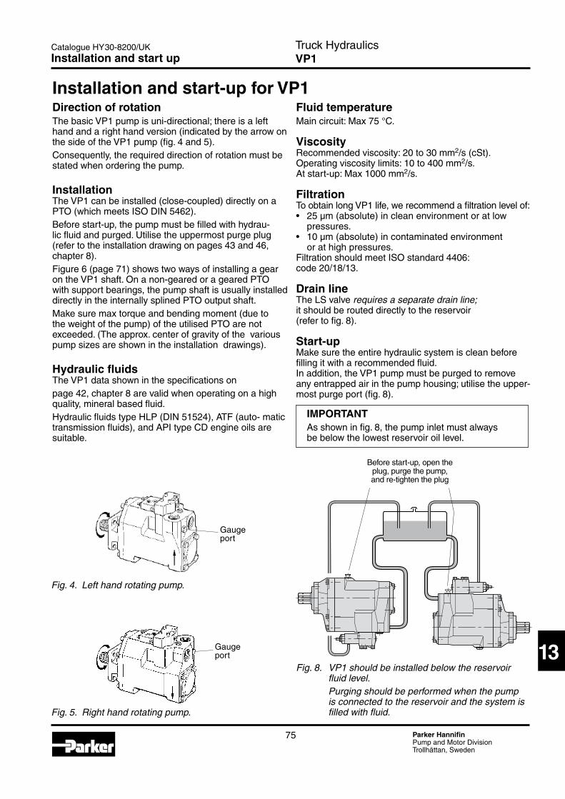
75 Parker HannifinPump and Motor DivisionTrollhättan, Sweden
Catalogue HY30-8200/UK
Fig. 8. VP1 should be installed below the reservoir fluid level. Purging should be performed when the pump is connected to the reservoir and the system is filled with fluid.
Fluid temperatureMain circuit: Max 75 °C.
ViscosityRecommendedviscosity:20to30mm2/s (cSt). Operating viscosity limits: 10 to 400 mm2/s.At start-up: Max 1000 mm2/s.
FiltrationTo obtain long VP1 life, we recommend a filtration level of:• 25µm(absolute)incleanenvironmentoratlow
pressures.• 10µm(absolute)incontaminatedenvironment
or at high pressures.Filtration should meet ISO standard 4406: code 20/18/13.
Drain lineTheLSvalverequires a separate drain line; it should be routed directly to the reservoir(refer to fig. 8).
Start-upMake sure the entire hydraulic system is clean before filling it with a recommended fluid.In addition, the VP1 pump must be purged to remove any entrapped air in the pump housing; utilise the upper-most purge port (fig. 8).
IMPORTANTAs shown in fig. 8, the pump inlet must always be below the lowest reservoir oil level.
Truck HydraulicsVP1
VP1_below_tank_GB.epsLeif A./020115
Before start-up, open the plug, purge the pump, and re-tighten the plug
Direction of rotationThe basic VP1 pump is uni-directional; there is a left hand and a right hand version (indicated by the arrow on the side of the VP1 pump (fig. 4 and 5).Consequently, the required direction of rotation must be stated when ordering the pump.
InstallationThe VP1 can be installed (close-coupled) directly on a PTO (which meets ISO DIN 5462).Before start-up, the pump must be filled with hydrau-lic fluid and purged. Utilise the uppermost purge plug (refer to the installation drawing on pages 43 and 46, chapter 8).Figure 6 (page 71) shows two ways of installing a gear on the VP1 shaft. On a non-geared or a geared PTO with support bearings, the pump shaft is usually installed directly in the internally splined PTO output shaft.Make sure max torque and bending moment (due to the weight of the pump) of the utilised PTO are not exceeded. (The approx. center of gravity of the various pump sizes are shown in the installation drawings).
Hydraulic fluidsThe VP1 data shown in the specifications on page 42, chapter 8 are valid when operating on a high quality, mineral based fluid.HydraulicfluidstypeHLP(DIN51524),ATF(auto-matictransmission fluids), and API type CD engine oils are suitable.
Fig. 4. Left hand rotating pump.
Fig. 5. Right hand rotating pump.
Gaugeport
Gaugeport
Installation and start-up for VP1
Installation and start up
13

Catalogue HY30-8200/UK. 1M 01/2013 ZZ© 2013 Parker Hannifin Corporation. All rights reserved.
Your local authorized Parker distributor
Ed
. 201
2-11
-01
Parker WorldwideEurope, Middle East, AfricaAE – United Arab Emirates, Dubai Tel: +971 4 8127100 [email protected]
AT – Austria, Wiener Neustadt Tel: +43 (0)2622 23501-0 [email protected]
AT – Eastern Europe, Wiener Neustadt Tel: +43 (0)2622 23501 900 [email protected]
AZ – Azerbaijan, Baku Tel: +994 50 22 33 458 [email protected]
BE/LU – Belgium, Nivelles Tel: +32 (0)67 280 900 [email protected]
BY – Belarus, Minsk Tel: +375 17 209 9399 [email protected]
CH – Switzerland, Etoy Tel: +41 (0)21 821 87 00 [email protected]
CZ – Czech Republic, Klecany Tel: +420 284 083 111 [email protected]
DE – Germany, Kaarst Tel: +49 (0)2131 4016 0 [email protected]
DK – Denmark, Ballerup Tel: +45 43 56 04 00 [email protected]
ES – Spain, Madrid Tel: +34 902 330 001 [email protected]
FI – Finland, Vantaa Tel: +358 (0)20 753 2500 [email protected]
FR – France, Contamine s/Arve Tel: +33 (0)4 50 25 80 25 [email protected]
GR – Greece, Athens Tel: +30 210 933 6450 [email protected]
HU – Hungary, Budaoers Tel: +36 23 885 470 [email protected]
IE – Ireland, Dublin Tel: +353 (0)1 466 6370 [email protected]
IT – Italy, Corsico (MI) Tel: +39 02 45 19 21 [email protected]
KZ – Kazakhstan, Almaty Tel: +7 7273 561 000 [email protected]
NL – The Netherlands, Oldenzaal Tel: +31 (0)541 585 000 [email protected]
NO – Norway, Asker Tel: +47 66 75 34 00 [email protected]
PL – Poland, Warsaw Tel: +48 (0)22 573 24 00 [email protected]
PT – Portugal, Leca da Palmeira Tel: +351 22 999 7360 [email protected]
RO – Romania, Bucharest Tel: +40 21 252 1382 [email protected]
RU – Russia, Moscow Tel: +7 495 645-2156 [email protected]
SE – Sweden, Spånga Tel: +46 (0)8 59 79 50 00 [email protected]
SK – Slovakia, Banská Bystrica Tel: +421 484 162 252 [email protected]
SL – Slovenia, Novo Mesto Tel: +386 7 337 6650 [email protected]
TR – Turkey, Istanbul Tel: +90 216 4997081 [email protected]
UA – Ukraine, Kiev Tel +380 44 494 2731 [email protected]
UK – United Kingdom, Warwick Tel: +44 (0)1926 317 878 [email protected]
ZA – South Africa, Kempton Park Tel: +27 (0)11 961 0700 [email protected]
North AmericaCA – Canada, Milton, Ontario Tel: +1 905 693 3000
US – USA, Cleveland (industrial) Tel: +1 216 896 3000
US – USA, Elk Grove Village (mobile) Tel: +1 847 258 6200
Asia PacificAU – Australia, Castle Hill Tel: +61 (0)2-9634 7777
CN – China, Shanghai Tel: +86 21 2899 5000
HK – Hong Kong Tel: +852 2428 8008
IN – India, Mumbai Tel: +91 22 6513 7081-85
JP – Japan, Fujisawa Tel: +81 (0)4 6635 3050
KR – South Korea, Seoul Tel: +82 2 559 0400
MY – Malaysia, Shah Alam Tel: +60 3 7849 0800
NZ – New Zealand, Mt Wellington Tel: +64 9 574 1744
SG – Singapore Tel: +65 6887 6300
TH – Thailand, Bangkok Tel: +662 717 8140
TW – Taiwan, New Taipei City Tel: +886 2 2298 8987
South AmericaAR – Argentina, Buenos Aires Tel: +54 3327 44 4129
BR – Brazil, Cachoeirinha RS Tel: +55 51 3470 9144
CL – Chile, Santiago Tel: +56 2 623 1216
MX – Mexico, Apodaca Tel: +52 81 8156 6000
EMEA Product Information CentreFree phone: 00 800 27 27 5374(from AT, BE, CH, CZ, DE, DK, EE, ES, FI, FR, IE, IL, IS, IT, LU, MT, NL, NO, PL, PT, RU, SE, SK, UK, ZA)
US Product Information CentreToll-free number: 1-800-27 27 537
www.parker.com