tru waste characterization chamber gloveboxes/67531/metadc622116/m2/1/high... · tru waste...
TRANSCRIPT

TRU WASTE CHARACTERIZATION CHAMBERGLOVEBOXES
By
David S. D#aq Scott D. McBride, Max L. Howell
Technology Development DivisionEngineering Division
Argonne National Laboratory-WestP. O. BOX 2528
Idaho Fak, ID 83403-2528
The submitted manuscript has been createdby the University of Chicago as Operator ofArgonne National Laboratory ~Argonne-)under Contract No. W-31 -109-ENG-38 withthe U.S. Department of Energy. The U.S.Government retains for itself, and others act-ing on its behalf, a paid-up, nonexclusive,’irrevocable worldwide license in said articleto reproduce, prepare derivative works, dis-tribute copies to the public, and perform pub=Iicly and display publicly, by or on behalf ofthe Government.
.
To be presentedat
American Glovebox SocietyJllly 12-15, 1998Orlando, Florida
* work ~ppo~ by &e u. s. l)ep~ent ofEnergy, ~ce of Nucl~ Energy, Scienm ad TWIUIOIO~, ad theOfKeeof Environmental Management under contract W-31-109-Eng-38.
.——— - .
DISCLAIMER
This report was prepared as an account of work sponsoredby an agency of the United States Government. Neither theUnited States Government nor any agency thereof, nor anyof their employees, make any”warranty, express or implied,or assumes any legal liability or responsibility for theaccuracy, completeness, or usefulness of any information,apparatus, product, or process disclosed, or represents thatits use would not infringe privately owned rights. Referenceherein to any specific commercial product, process, or
,service by trade name, trademark, manufacturer, orotherwise does not necessarily constitute or imply itsendorsement, recommendation, or favoring by the UnitedStates Government or any agency thereof. The views andopinions of authors expressed herein do not necessarilystate or reflect those of the United States Government orany agency thereof.
.—
DISCLAIMER
Potiions of this document-may be illegiblein electronic image products. Images areproduced from the best available originaldocument.
\
.-. — .——. \-n --T-.-.< ., . . . . ,.., ,. .,. . . . . . . . -*-._. _. ..— .
David S. DuncanScott R. McBrideMax L, HowellArgonne National Laboratory - WestIdaho Falls, Idaho 83403
TRU WASTECHARACTERIZATION GLOVEBOXES
Abstracfi Argonne National Laboratory-West (ANL-W) is participating in theDepartment of Energy’s (DOE) National Transuranic Waste Program in support ofthe Waste Isolation Pilot Plant (WIPP). The Laboratory’s support currently consistsof intrusive characterization of a selected population of drums containingtransuranic waste. This characterization is performed in a complex of alphacontainment gloveboxes termed the Waste Characterization Gloveboxes. Made upof the Waste Characterization Chamber, Sample Preparation Glovebox, and theEquipment Repair Glovebox, they were designq as a small productioncharacterization facility for support of the Idaho National Engineering andEnvironmental Laboratory (INEEL). This paper presents salient features of thesegloveboxes.
INTRODUCTION
Argonne National Laboratory-West is participating in the Department of Energy’s (DOE)National Transuranic Waste Program, in support of the Waste Isolation Pilot Plant (WIPP)l. It hasdeveloped a facility to characterize and repackage drums of contact-handled transuranic (CH-TRU)mixed waste from the Idaho National Engineering and Environmental Laboratory (INEEL). Thisfacility, termed the Waste Characterization Area (WCA)2, is located within Argonne’s Hot FuelExamination Facility (HFEF)3, in the high bay area. The WCA is a series of processing roomssurrounding three alpha containment gloveboxes. These boxes, called the Waste CharacterizationGloveboxes, are used to support the characterization process at HFEF. Limited space at HFEF andthe need to characterize a production volume of drums, drove the design and layout presented inFigure 1.
The Idaho National Engineering and Environmental Laboratory (INEEL) is one of the firstDOE complex sites scheduled to ship waste to WJPP. All waste proceeding to WIPP must becharacterized to meet repository license requirements established by the State of New Mexico andthe Environmental Protection Agency (EPA). WIPP-required characterization consists of headspacegas sampling , non-destructive assay to determine radioisotope inventory, and non-destructiveexamination in the form of real-time radiography to determine the waste’s physical character. Aselected sample of the total waste destined for WIPP must be intrusively characterized. Intrusivecharacterization consists of opening the drunx removing, cataloging, and weighing its contents fordebris waste or extracting a core sample for homogeneous wastq and re-packaging the contents, ifpracticable, into a new, polyethylene-lined waste drum This effort is required to certify the validityof the non-destructive examinations performed on the total waste volume planned for shipment. Theamount of waste from the total population required to undergo intrusive characterization variesamong waste types and generator sites, and is based on previous characterization activities.
---- ..,..7+= ,, .,, .,, .,.. . . . . . . . . . . . . . . . . . . . . . . . . -m; .Yn-. ,), , , . . . . . ., ., . .—— ,m—
i
1

WASTE
1[SLUDGE CORING
CiiARAClERlZAl10t4 UAOilNECNAMBER f WOE UANIPULATCRS
REPAIR U.0Vi80X\ II HEPA flLIERS
(i/
EQUIPMENT ROOM
4
OPERAIONS ROOM
SAMPLE PREPARAllC!+4 CIO~OX
rWASIE DRUMS
L HFEF HOT REPAIR ARSA ~ ~AN~ER ROOM ~ PR~ARAmoN ROOM
F~e 1. WXPPWASTECHARAcnzrU%4TIONAREA
The TRU Waste Characterization Gloveboxes were proposed in 1990 to improve characterizationand repackaging operations performed in HFEF’s Hot Repair Area in support of the NationalTransuranic Waste Program. They would provide a dedicated facility for WIPP operations, allowingincreased throughput and greater characterization capabilities. These gloveboxes would be built ina limited available area of the HFEF high bay and would make productive use of a previously unusedspace. Construction of the boxes in the High bay would allow the HFEF safety assessment toenvelope their future productive work and would decrease the cost normally in&rred for this typeof facility. The boxes would also reduce the potential for alpha contamination spread in HFEF andreduce the potential for radiation exposure to operators. As such this proposed modification toHFEF was supported by the National Transuranic Waste Program.
The TRU Waste Characterization Gloveboxes are designed in accordance with DOES GeneralDesign Criteri%formerly DOE Order 6430.lA, including Division 13, ‘Special Facilities,’ applicableparagraphs of Sections 1300, ‘General Requirements’, and 1324, ‘Radioactive Solid WasteFacilities’. No safely-class structures, components, or systems, as defined by this order, are requiredfor this facility. Waste drum handling and characterization operations fall within HFEF’s existingsafety envelop~ hence, no unreviewed safety questions were raised in a detailed assessment of theseoperations 4.
!
Ii
t I
II
Three levels of confinement are defined by these gloveboxes and their positioning withinHFEF. Two separate systems, the cell exhaust and the laboratory exhaust, ventilate the primary andsecondary cotilnements. Facility locations with the greatest potential for contamination aremaintained at negative pressure with respect to locations with lower potential for contamination.Ventilation air flows inward from the outermost confinement boundary to the glovebox interiors.Contaminated air exhaust from inside the gloveboxes is filtered by at least two in-series banks ofHEPA filters and an adsorbing carbon filter.
I. ,........... ,1 . ,,,. . ,. .
./. . . . . . . . . . . . . . .
— -,=-= ---T’cz,.. ... .,:.,f I
The characterized CH-TRU waste consists of a variety of materi~s and packaging con-figurations, including debris such as paper, cardboard, plastic, rubber, glass, ceramics, and metals.Homogeneousmaterial is also included such as radioactive material production process sludges. Thewaste is contaminated with radioactive and hazardous constituents. Most of the waste beingcharacterized originated from Roe@ Flats. Rocky Flats waste is contaminated primarily with aweapons-grade plutonium isotope mixture (commonly referred to as Pu-52) and the ingrowthproduct, americium-241. Approximate weight percentages of the key isotopes are Pu-238, 0.01 %;Pu-239, 93.8%; Pu-240, 5.8%; Pu-241, 0.4%; Pu-242, 0.002%; and AIn-241, 0.4704.Key hazardousconstituents considered in environmental analyses for the WCA include 1,1, l-trichloroethane,
-carbon tetrachloride, 1,1,2-trichloroethene, 1,2,2-trifluoroethane, trichloroethylene, methylenechloride, methyl alcohol, butyl alcohol, xylene, cadmium, lead, mercury, be@hun, asbestos,lithium, and nitric acid. The design basis for this facility assumes a maximum of 400 drums (208-Llter size) can be characterizedhepackaged per year.
TRU WASTE CHARACTERIZATION GLOVEBOXES
The TRU Waste Characterization Gloveboxes, consisting of the Waste CharacterizationChamber (WCC), the Equipment Repair Glovebox (ERB), and the Sample Preparation Glovebox(SPB), have been built in a limited space to optimize a small scale intrusive characterizationprocess. The first of these gloveboxes has been operational since April 1994. Over four-hundreddrums of debris and residue waste have been processed since operations began. All work performedon alpha-contaminated TRU waste and related contaminated equipment is performed in one of thesethree boxes.
The WCC was the first of the gloveboxes to be fabricated and installed. This box beganradioactive material operations in April 1994. Subsequently, in September 1994, operations werecurtailed for an approximate 8-month period to add the remaining two boxes. The SPB and theERBwere interfaced to the WCC, which was already contaminated, without ticurring spread ofcontamination outside the original confinement boundary.
These boxes exist to protect the worker from alpha contamination and radiation exposure. Theyare protected by a dedicated C02 Fire Protection System (FPS), certified to achieve a minimum of20% C02 concentration for a period of at least 20 minutes following a fire event. During the event,the glovebox ventilation system is isolated from the facility ventilation system. In the paragraphswhich follow, the purpose and salient features will be presented for each glovebox.
Waste Characterization Chamber
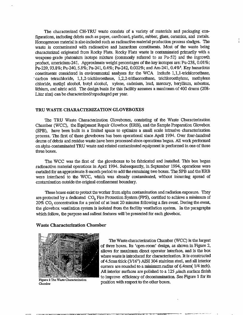
I?igure 2 The Wasto CharacterizationChember
The Waste characterization Chamber (WCC) is the largestof three boxes. Its ‘open-room’ design, as shown in Figure 2,allows for maximum direct operator interface, and is the boxwhere waste is introduced for characterization. It is constructedof 4.5mm thick (3/16“) AISI 304 stainless steel, and all interiorcorners are rounded to a minimum radius of 6.4mm( 1/4 inch).All interior surfaces are polished to a 125 pinch surface finishto improve efficiency of decontamination. See Figure 1 for itsposition with respect to the other boxes.
...— ..——- —.— -- .. . ...— —-.Tmr-.-—.-—. — .,
Three sides of the 2.4x 4.5 meter (8’x 15’)rectangular box, are windowed with a total of eight,- l-meter (36”) square panes of LEXAN@Model MR-4000 polycarbonate. This material has HighUV yellowing resistance, acts as part of the primary containment boundary, and provides superiorimpact resistance. Laminated safety glass panes overlay the interior of the LEXAN@windows forprotection from f~e. Leaded glass laminate panes overlay the window exteriors to reduce radiationexposure. Twenty -two access glove ports (Central Research Model C-18885, push-thro@h type)are inset into the LEXAN@windows to optimize operator access and view ability.
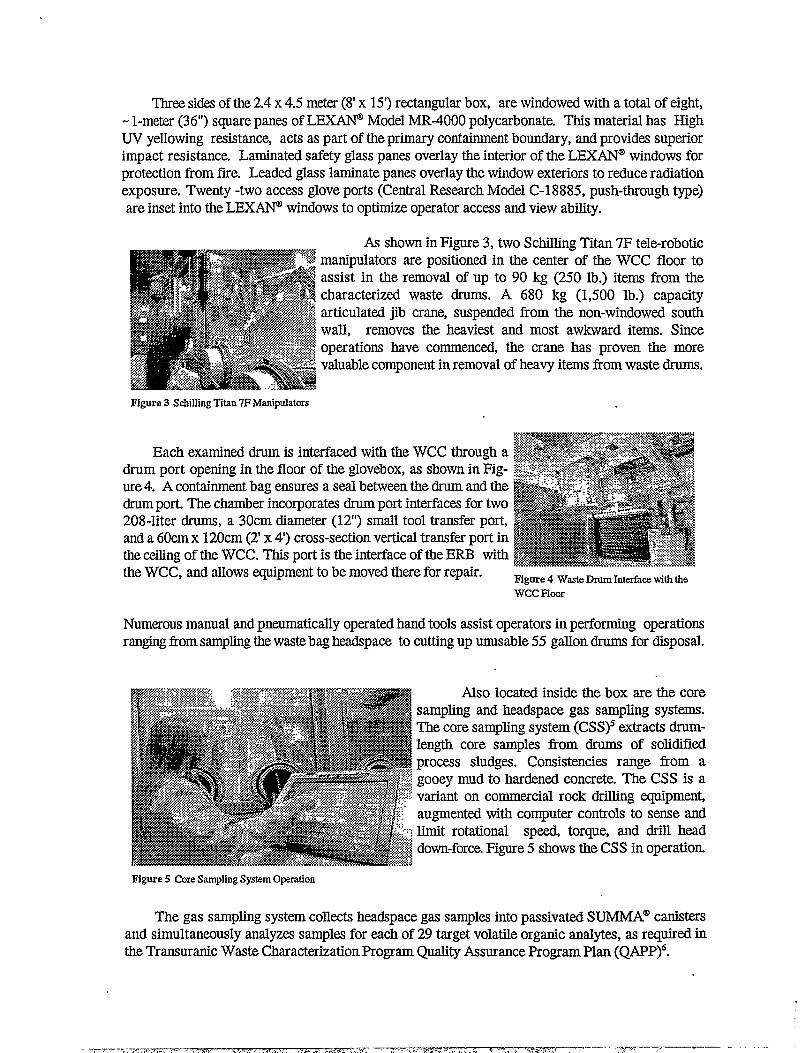
As shown in Figure 3, two Schilling Titan 7F tele-roboticmanipulators are positioned in the center of the WCC floor toassist in the removal of up to 90 kg (250 lb.) items from thecharacterized waste drums. A 680 kg (1,500 lb.) capacityarticulated jib crane, suspended from the non-windowed southwall, removes the heaviest and most awkward items. Sinceoperations have commenced, the crane has proven the morevaluable component in removal of heavy items from waste drums.
Figure 3 SchiHingTkm 7F Manipulators
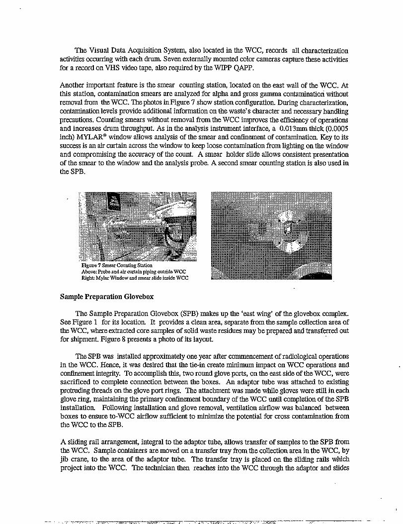
Each examined drum is interfaced with the WCC through adrum port opening in the floor of the glovebox, as shown in Fig-ure 4. A containment bag ensures a seal between the drum and thedrum port. The chamber incorporates drum port interfaces for two208-liter drums, a 30cm diameter (12”) small tool transfer port,and a 60cm x 120cm (2’x4’) cross-section vertical transfer port inthe ceiling of the WCC. This port is the interface of the ERB withthe WCC, and allows equipment to be moved there for repair. Figure 4 Waate Drum Interface with the
WCC Floor
Numerous manual and pneumatically operated hand tools assist operators in performing operationsranging from sampling the waste bag headspace to cutting up unusable 55 gMon drums for disposal.
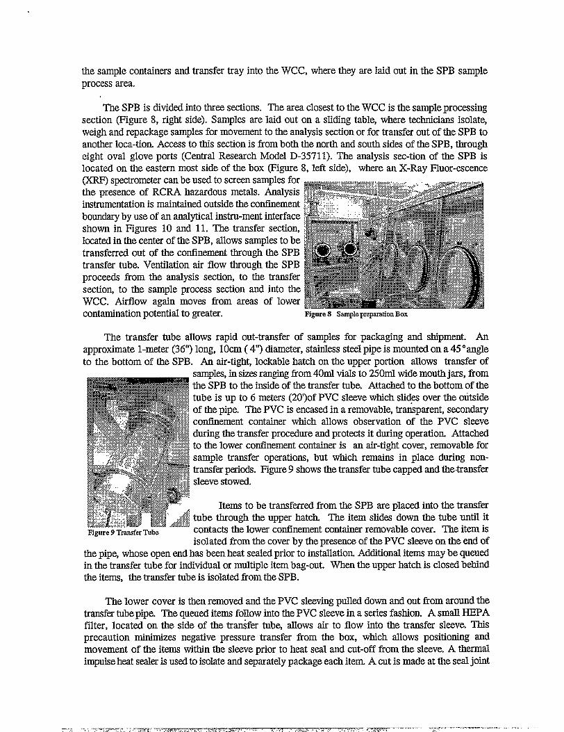
Also located inside the box are the coresampling and headspace gas sampling systems.The core sampling system (CSS)5 extracts drmn-length core samples from drums of solidifiedprocess sludges. Consistencies range from agooey mud to hardened concrete. The CSS is avariant on commercial rock drilling equipment,augmented with computer controls to sense andlimit rotational speed, torque, and drill headdown-force.Figure 5 shows the CSS in operation.
Figure 5 Core Sampling System Operation
The gas sampling system collects headspace gas samples into passivated SUMMA@canistersand simultaneously analyzes samples for each of 29 target volatile organic analytes, as required inthe Transuranic Waste Characterization Program Quality Assurance Program Plan (QAPP)G.
.J m. .Ty.,,, 4 .,-3,, ,.., ,. ..,. T?+zmm?---- -—- -w,.: .,
The Visual Data Acquisition System, also located in the WCC, records all characterizationactivities occuming with each drum. Seven externally mounted color cameras capture these activitiesfor a record on VHS video tape, also required by the WIPP QAPP.
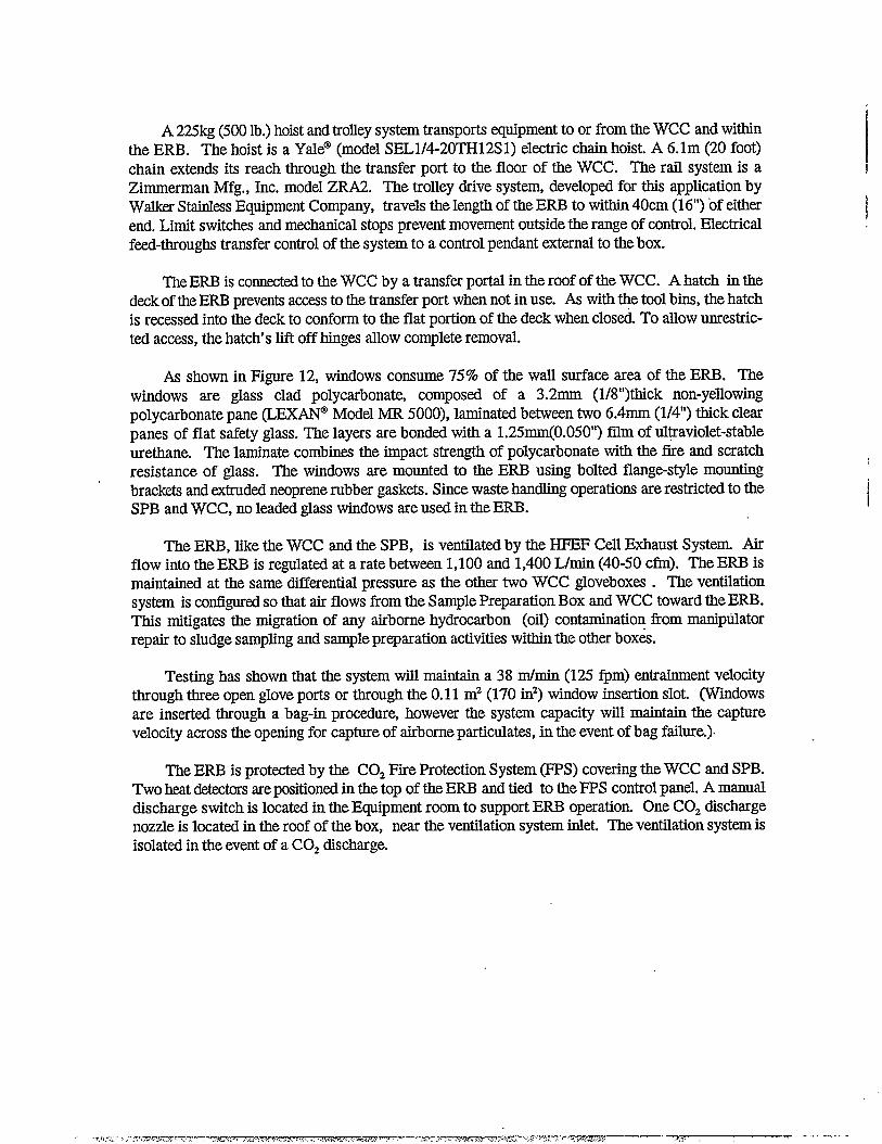
Another important feature is the smear counting station, located on the east wdl of the WCC. Atthis station, contamination smears are analyzed for alpha and gross gamma contamination withoutremoval from the WCC. The photos in Figure 7 show station configuration. During characterization,contamination levels provide additional information on the waste’s character and necessary handlingprecautions. Counting smears without removal from the WCC improves the efficiency of operationsand increases drum throughput. As in the amdysis instrument interface, a 0.013mm thick (0.0005inch) MYLAR@window allows analysis of the smear and confinement of contamination. Key to itssuccess is an air curtain across the window to keep loose contamination from lighting on the windowand compromising the accuracy of the count. A smear holder slide allows consistent presentationof the smear to the window and the analysis probe. A second smear counting station is also used inthe SPB,
Figure 7 Smear Counting StationAbove: Probe and air certain piping outside WCCRighti Mylar Window and smear slide inside WCC
Sample Preparation Glovebox
The Sample Preparation Glovebox (SPB) makes up the ‘east wing’ of the glovebox complex.See Figure 1 for its location. It provides a clean area, separate from the sample collection area ofthe WCC, where extracted core samples of solid waste residues maybe prepared and transferred outfor shipment. Figure 8 presents a photo of its layout.
The SPB was installed approximately one year after commencement of radiological operationsin the WCC. Hence, it was desired that the tie-in create minimum impact on WCC operations andconfinementintegrity. To accomplish this, two round glove ports, on the east side of the WCC, weresacrificed to complete connection between the boxes. An adaptor tube was attached to existingprotruding threads on the glove port rings. The attachment was made while gloves were still in eachglove ring, maintaining the primary confinement boundary of the WCC until completion of the SPBinstallation. Following installation and glove removal, ventilation airflow was balanced betweenboxes to ensure to-WCC airflow sufficient to minimize the potential for cross contamination fromthe WCC to the SPB.
A sliding rail arrangement, integral to the adaptor tube, allows transfer of samples to the SPB fromthe WCC. Sample containers are moved on a transfer tray from the collection area in the WCC, byjib crane, to the area of the adaptor tube. The transfer tray is placed on the sliding rails whichproject into the WCC. The technician then reaches into the WCC through the adaptor and slides
t
—-. , ,7 .:, ,,, ,=.
. ,<>” . . . ,- . .,, ..,~.,=.~, .-.. .. >- ——-.—: ‘“. .. . .. . . . . . ., ~ ., ,. , . . :-x-.sm ,(.-.—.— -
the sample containers and transfer tray into the WCC, where they are laid out in the SPB sampleprocess area.
The SPB is divided into three sections. The area closest to the WCC is the sample processingsection (Figure 8, right side). Samples are laid out on a sliding table, where technicians isolate,weigh and repackage samples for movement to the analysis section or for transfer out of the SPB toanother loca-tion. Access to this section is from both the north and south sides of the SPB, througheight oval glove ports (Central Research Model D-3571 1). The analysis sec-tion of the SPB islocated on the eastern most side of the box (Figure 8, left side), where an X-Ray Fluor-escence(XRF) spectrometer can be used to screen samples forthe presence of RCRA hazardous metals. Analysisinstrumentation is maintained outside the confinementboundary by use of an analytical instru-ment interfaceshown in Figures 10 and 11. The transfer section,lccated in the center of the SPB, allows samples to betransferred out of the cotilnement through the SPBtransfer tube. Ventilation air flow through the SPBproceeds from the analysis section, to the transfersectio~ to the sample process section and into theWCC. Airflow again moves from areas of lowercontamination potential to greater. Figure 8 Sample preparation Box
The transfer tube allows rapid out-transfer of samples for packaging and shipment. Anapproximate l-meter (36”) long, 10cm ( 4“) diameter, stainless steel pipe is mounted on a 45 “angleto the bottom of the SPB. An air-tight, lockable hatch on the upper portion allows transfer of
Figure 9 Transfer Tube
samples, in sizes ranging from 40ml vials to 250ml wide mouth jars, fromthe SPB to the inside of the transfer tube. Attached to the bottom of thetube is up to 6 meters (20’)of PVC sleeve which slid-esover the outsideof the pipe. The PVC is encased in a removable, transparent, secondaryconllnement container which slows observation of the PVC sleeveduring the transfer procedure and protects it during operation. Attachedto the lower cotinement container is an air-tight cover, removable forsample transfer operations, but which remains in place during non-transfer pticds. Figure 9 shows the transfer tube capped and the transfersleeve stowed.
Items to be transferred from the SPB are placed into the transfertube through the upper hatch. The item slides down the tube until itcontacts the lower confinement container removable cover. The item isisolated from the cover by the presence of the PVC sleeve on the end of
the pipe, whose open end has been heat sealed prior to ins~allation. Additional items maybe queuedin the transfer tube for individual or multiple item bag-out. When the upper hatch is closed behindthe items, the transfer tube is isolated fiomthe SPB.
The lower cover is then removed and the PVC sleeving pulled down and out from around thetransfer tube pipe. The queued items follow into the PVC sleeve in a series fashion. A small HEPAfilter, located on the side of the trfifer tube, allows air to flow into the transfer sleeve. Thisprecaution minimizes negative pressure transfer from the box, which allows positioning andmovement of the items within the sleeve prior to heat seal and cut-off from the sleeve. A thermalimpulse heat sealer is used to isolate and separately package each item. A cut is made at the seal joint
--- J .-, . -.-=. ?----- -- ,T!T-77- ,. ,,<=., . . . . . ..-. ./ . ...<.. ,?-.,. . . .. . . - . . . . . -“ .. , . . . . . .. :. .r?7- ~~——— . , .; -.. ..— . . .

and the extracted item is considered “packaged” for storage or shipment. Potential contaminationis sealed inside a “bag” with a clean exterior. Any unused PVC sleeving is stowed up around thetransfer tube and the lower cover is replaced.
When the sleevinghas been consumed, the lower confinement container is removed. New PVCsleeving, with one end heat sealed, is slid up around the old PVC sleeve stub and sealed to the topof the transfer tube. The PVC sleeve stub is removed and discarded using the transfer techniquepreviously presented, and the confinement container is replaced.
Inihe analysis section of the SPB, an analytical instrument interface allows use of a Spectrace9000 portable analyzer for sample screening of RCRA hazardous metals. A sensor mating interface
I?igure 10 Analytical Instrument Interfacewith protective rover removed
was developed with a replaceable receptacle and MYLAR@window to allow analysis without breach the SPB confinementboundary and without contaminating the analysis probe. Figure10 shows the sample interface inside the glovebox. TheMYLAR@window acts as the primary confinement boundaryand x-ray window for the analyzer. MYLAR@, 0.013mm(0.0005 inch) thiclG is attached to the window f@ne by meansof a retaining ring which snaps into place as it is forced downaround the MYLAR” material. The result is a taut, wrinklefree window which does not interfere with the awilysis of thesample presented at the window.
The instrument probe is bolted into a machined receptacle—-.,under the SPB floor, which also holds the window frame. Thisreceptacle, which is shown in Figure 11, acts as a secondaryconfinement boundary in the event the window is compromised.The MYLAR@window is replace4 with its f&me, by loweringthe detector probe, removing the old frame, and inserting the
ri’wq new. The SpB negativepr~s~e and theS.gcm (1.5”)diameter$$$&’
hole, present during fiane replacement, ensures sufficientpj: ,.+ entrainment velocity to minimizelprevent contamination spread
—z ....%EZZZZE~!2 S4Figure 11 Instrument Probe Connectedon
during the replacement procedure. The MYLAR@window and
the outside of the interfaceframe were verified capable of withstanding the 100mrn (4”)water gauge, design pressure of the SPB.
&w%’ ““‘“’””P*......ttj-~.,,,,=....,,,.?/y<:;..:.&v& fx’ ,fy’ ....:
) /.”.; ,.+ ;::-
Equipment Repair Glovebox
The E@pment Repair Glovebox (ERB) is the third of the Waste Characterization Gloveboxes.It is located in the WCA Equipment Room directly above the WCC. See Figure 1 for its location.The ERB is used for repair of plutonium contaminated equipment horn the WCC. The box willsupport repair and limited operation of either Schilling@Titan 7F, or Central Research Labora-tories Model L, manipulators. The ERB can also be used for service, repair, and check-out of theWCC jib crane winch/motor assembly. Replacement inner pane window assemblies for the WCCare transferred into the WCC interior through the ERB.
TheERB is fabricated fiom4.5mmthick (3/16”),AISI 304 stainless steel. The interior surfaceis finished to 125pin to facilitate decontamination and cleaning. Light fixtures are mounted on thewindow exteriors to provide interior illumination. The installed box is approximately 2.7 meters (9’)
~. .. ,.:--,~,---.-,- -,.. .. . ........ , . ,,,1.., ,, ,... r>., , .. . . . f, m ——- ,:;, ,-

high with an overall length of 4.9 meters (16 feet). Ventilation and fire protection are provided bysystems supporting all the gloveboxes, and which have been described previously. The loaded ERBimposes a maximum flcor load (to Equipment Room floor) of 340 kg/m2 (70 lb/ft2) with a maximumpoint load of 360kg (800 lb.). The loaded ERB will remain intact when subjected to the design basisearthquake stipulated in DOE Order 6430.1A. Its design pressure differential is 100mm (4”) water.
As depictedinFi~e 12, The ERB consists of two sections with different profiles. The repairsection is 86cm (34”) wide at the working (deck)level and tapers up to a 43cm (17”) ceiling. Operator :,~
[
. . .
Access is through 10 oval glove ports ( CRL Model ‘&@!D-35711) on both sides of this section. The difference :~in ceiling and floor widths slopes the windows to an ~angle of 10° from vertical to reduce glare and max- $
fimize operator view. The 3-meter (- 10’)length of this “’section accommodates repair and maintenance of Fmanipulators. A detail work area is located on thesouth end of the repair section. It is 40cm long x I73cm (29”)widex 46cm (18”) high. This area allows “’”direct technician access to intricate mechanisms @+:~~b$~=” ..’?%:$?z.:.<:.<$~~~~~’<J..<+.....ti. ......>ti.... ..h...ti.. ,....xw:d~
while looking directly over the work piece. Four (4) ‘gme 12 ‘tipmnt ‘eptiBoxround glove ports (CRL Model C-18885) provide ready access to this area. Figure 12 shows a viewof the tapered repair section.
The working level (deck) of the repair section is 106cm (42”) above the floor of the WCAEquipment room. Oval glove ports are positioned 140cm (55”) above the Eqpipment Room floor.They are spaced as close as possible to the ideal 53cm (21”) center-to-center spacing. Round portsare used for access to the detailed repti area and for maintenance of the hoist and trolley. Theseven 20cm(8”) diameter round ports are the same CRL model C-18885 (push through-type) portsutilized in both the WCC and the SPB. One port is used for smrill tool insertion. -
Five (5) tool bins are inset below the working dezk Bins are nominally 30cm (12”) wide x30cm(12”) deep, and run adjacent to the windows on either side. A removable lid covers each biurecessed into the deck so that it forms a flat portion of the deck when in place. Two rows of blind,?4-16 UNC x s%”deep, threaded holes are located on 15cm (6”) centers along the deck centerline.Vices, holding fixtures, or similar items maybe mounted hereto facilitate tie repair of manipulatorsand other equipment. The deck and tool bins will support 450kg(l ,000 lb.). of tools, fixtures, andequipment.
The transfer section of the ERB is rectangular. Approximately 120cm (48”) wide, it forms anearly square work area to repair bulkier items such as the WCC jib crane winch assembly. l-metersquare vertical windows on three sides of the section, contain 6 oval glove ports. A 10cm (4”) x110cm (43”) vertical slot is built into the wall of this section to allow insertion of replacement innerwindow panes for the WCC.
Hydraulic lines are routed from the manipulator hydraulic pump to the ERB to permit in-boxmanipulator troubleshooting, test operation, and check out. Schilling@electronic feed-throughs passmanipulator control to a standard schilling manipulator control console. Two repair fixtures holdthe slave manipulator in such a way as to permit limited range movement while energized during testoperation. Fee&through AC electrical power outlets and plant air(37 L/see at 550 kpA(80 scfin at80 psi)) allow in-box use of small pow~ tools, etc.
i’
!
-,r’- ,-- --,-.,.-,.-. ..- . . -m- -- ?--- .7< , >..-- . . . . . . . . . . . . . . . . . -,., . ,. ..— -. -—
A 225kg (500 lb.) hoist and trolley system transports equipment to or from the WCC and withinthe ERB. The hoist is a Yale” (model SEL1/4-20TH12Sl) electric chain hoist. A 6. lm (20 foot)chain extends its reach through the transfer port to the floor of the WCC. The rail system is aZimmerman Mfg., Inc. model ZRA2. The trolley drive system, developed for this application byWalker Stainless Equipment Company, travels the length of the ERB to within 40cm (16”) of eithexend, Limit switches and mechanical stops prevent movement outside the range of control. Electricalfeed-throughs transfer control of the system to a control pendant external to the box.
TheERB is connectedto the WCC by a transfer portal in tie roof of the WCC. A hatch in thedeck of the ERB prevents access to the transfer port when not in use. As with ~e tool bins, the hatchis recessed into the deck to conform to the flat portion of the deck when closed. To allow unrestric-ted access, the hatch’s lift off hinges allow complete removal.
As shown in Figure 12, windows consume 75% of the wall surface area of the ERB. Thewindows are glass clad polycarbonate, composed of a 3.2mm (1/8’’)thick non-yellowingpolycarbonate pane (LEX@ Model MR 5000), laminated between two 6.4mm (1/4”) thick clearpanes of flat safety glass. The layers are bonded with a 1.25mm(0.050”) fihn of ul~aviolet-stableurethane, The laminate combines the impact strength of polycarbonate with the fire and scratchresistance of glass. The windows are mounted to the ERB using bolted flange-style mountingbrackets and extruded neoprene rubber gaskets. Since waste handling operations are restricted to theSPB and WCC, no leaded glass windows are used in the ERB.
The ERB, like the WCC and the SPB, is ventilated by the HFEF Cell Exhaust System. Airflow into the ERB is regulated at a rate between 1,100 and 1,400 Lhnin (40-50 cfin). The ERB ismaintained at the same differential pressure as the other two WCC gloveboxes . The ventilationsystem is configuredso that air flows nom the Sample Preparation Box and WCC toward the ERB.This mitigates the migration of any airborne hydrocarbon (oil) contamination ffom maniptiatorrepair to sludge sampling and sample preparation activitim within the other boxes.
Testing has shown that the system will maintain a 38 mhnin (125 fpm) entrainment velocitythrough three open glove ports or through the 0.11 m2 (170 in2) window insertion slot. (Windowsare inserted through a bag-in procedure, however the system capacity will maintain the capturevelocity across the opening for capture of airborne particulate, in the event of bag failure.).
The ERB is protected by the C02 Fire Protection System (FPS) covering the WCC and SPB.Two heat detectors repositioned in the top of the ERB and tied to the FPS control panel. A manualdischarge switch is located in the Equipment room to support ERB operation. One C02 dischargenozzle is located in the roof of the box, ntm the ventilation system inlet. The ventilation system isisolated in the event of a C02 discharge.
i
-,,r, T- , .------. -.V7-T’-S? . . .. . . , . ,- ----- ... .. . ..— — r . I
SUMMARY
The need for a dedicated facility to conduct characterization operations has driven the designof these gloveboxes. Lessons learned from day-to-day characterization and analysis have evolvedinto many of the equipment designs presented in this paper. This equipment has greatly improvedthe efficiency of characterization operations at ANL-W. Many DOE complex sites are beginningto determine what facilities are needed to cert@ their waste for shipment to WIPP. These designscan be valuable in determining the layout and makeup of future characterization facilities.
REFERENCES
1.
2,
3.
4.
5.
6.
Department of Energy, “National Transuranic Waste Management Plan”, NTP-96-1204,Revision 01, United States Department of Energy Carlsbad Area Oj$ce, Carlsb@ NM(December 1997).
Dunc~ David S., &al., “Argome-West Waste Characterization Area for Mixed TRU Waste”,Proceedings of Nuclear and Hazardous Waste Management International Topical Meeting-SPECTRUM ’94,356-360, Atlant6 GA (August 1994).
Bacc& J.P., “Update on the Hot Fuel Examination Facility (IIFEl?) Complex”, Proceedings ofthe 33rd Conference on Remote Systems Technology, 146-153, San Francisco, CA (November1985).
Black D.B., “ANL-W WIPP Project Safety Assessment for HFEF WCA Operations”, ArgonneNational Laboratory Internal Report, WO096-0161-D?L (December 1993).
Duncan, David S., et.al., “A Sludge Sampling System for CH-TRU Mixeii Waste at ArgonneNationaS Laboratory - West”, Proceedings of the 42nd Conference on Robotics and RemoteSystems Technology, American Nuclear Sociezy, 31-34, Washington, D.C. (November 1994).
Department of Energy, “Transura.nic waste Characterization Quality Assurance Program Plan,CAO-94-1O1O, Revision O, United States Department of Energy Carlsbad Area Ofiice,Carlsbad, NM (April 1995).