troubleshooting wireless mesh networks victor bahl [email protected] joint work with lili qiu,...
TRANSCRIPT

Troubleshooting Wireless Mesh Networks
Victor [email protected]
joint work with Lili Qiu, Ananth Rao (UCB) & Lidong Zhou
Microsoft Research
April 1, 2004

Mesh Network Management
ISO’s definition of network management: – Fault Management– Configuration Management– Security Management– Performance management– Accounting
“Network management is a process of controlling a complex data network so as to maximize its efficiency and productivity”

Goals
Assist with Mesh Router configuration
Reactive and Pro-active Trouble Shooting– Investigate reported performance problems
• Time-series analysis to detect deviation from normal behavior– Localize and Isolate trouble spots
• Collect and analyze traffic reports from mesh nodes– Determine possible causes for the trouble spots
• Interference, or hardware problems, or network congestion, or malicious nodes ….
Respond to troubled spots– Re-route traffic– Rate limit– Change topology via power control & directional antenna control – Flag environmental changes & problems
Nomenclature
Mesh Management Module (M3)– Runs on every node
Mesh Management Server (MMS)– Runs on gateway or designated nodes
Mesh Network Management Protocol (MNMP)– Protocol (similar to SNMPv3) between M3 and MMS

Focus of this talk
• Gathering & Distribution Data
• Cleaning Data
• Fault Isolation & Diagnosis

Challenges in Fault Diagnosis
Characteristics of multi-hop wireless networks– Unpredictable physical medium, prone to link errors– Network topology is dynamic – Resource limitation calls for a diagnosis approach with low
overhead– Vulnerable to link attacks
Identifying root causes– Just knowing link statistics is insufficient– Signature Based Techniques don’t work well– Determining normal behavior is hard
Handling multiple faults– Complicated interactions between faults and traffic, and among
faults themselves

Previous Approaches to Fault Diagnosis
Protocols for Network Management• ANMP [singh99] • Guerrilla [shen02]
Detecting Routing and MAC misbehavior• Watchdog & pathrater [Baker00]• MACMis [Vaidya03]
Fault Management in Infrastructure mode• AirWave, AirDefense, UniCenter, Symbol’s WNMS, IBM’s
WSA, Wibhu’s SpetraMon, …

Our Approach
Use a network simulator as a real-time diagnostic tool

Fault Detection, Isolation & Diagnosis Process
Collect DataCleanData
DiagnoseFaults
Simulate
RawData
RootCauses
MeasuredPerformance
RoutesLink Loads
Signal Strength
InjectCandidate
Faults
PerformanceEstimate
Agent Module
Manager Module
• SNMP MIBs• Performance Counters• WRAPI• MCL• NativeWiFi

Wireless Network
Simulation
Link RSS
Link Load
Routing Update
+/-
Loss rate, Throughput, Noise,…
FaultsDirectory
NETWORK
REPORTS
Expected Loss rate, Throughput, Noise,...
Error
Topology Changes
InterferenceInjection
Error
{Link, Node, Fault}
Traffic Simulation
Delay
Root Cause Analysis Module

Our Fault Diagnosis Framework
Advantages– Flexible & customizable for a large class of
networks– Captures complicated interactions within the
network, between the network & environment, and among multiple faults
– Extensible in its ability of detecting new faults– Facilitates what-if analysis
Challenges– To accurately reproduce the behavior of the
network inside a simulator– To build a fault diagnosis technique using the
simulator as a diagnosis tool

Handling the Challenges
Reproducing network behavior• Identify the set of traces to collect • Rule out erroneous data from the trace• Drive the simulator with the cleaned traces
Building fault diagnosis• Use performance results from trace-driven
simulation to establish the normal behavior• Deviation from the normal behavior indicates a
potential fault• Identify root causes by efficiently search over
fault space to re-produce faulty symptoms

A B C D E
O P Q R S
F G
UT
F1 F2 F3 F4 F5
Why Simulator?
Flow1 Flow2 Flow3 Flow4 Flow5
2.5 Mbps 0.23 Mbps 2.09 Mbps 0.17 Mbps 2.55 Mbps
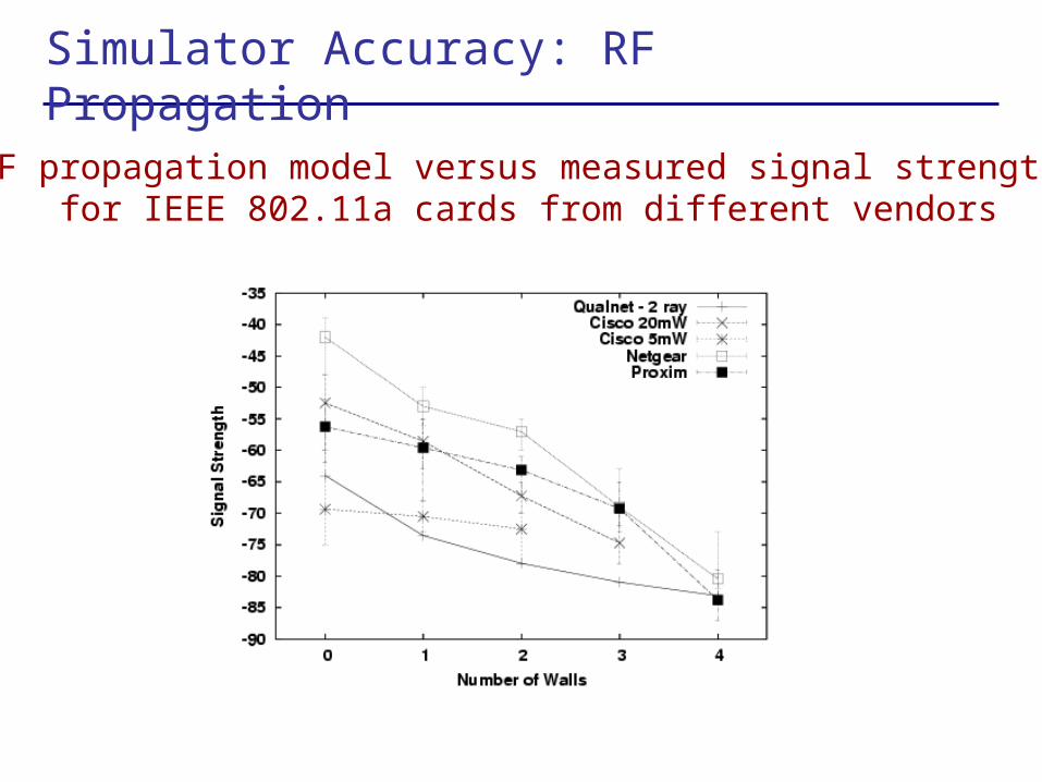
Simulator Accuracy: RF Propagation
RF propagation model versus measured signal strengthsfor IEEE 802.11a cards from different vendors

Simulator Accuracy: Throughput
Estimated versus actual throughput when channel conditions are good (IEEE 802.11a)

Simulator Accuracy: Throughput (2)
Estimated matches measured throughputtill the channel conditions become poor

Simulator Accuracy: Throughput
No. of Walls
Loss Rate
Measured Throughput
Simulated Throughput
4 11.0 % 15.52 Mbps 15.94 Mbps
5 7.01 % 12.56 Mbps 14.01 Mbps
6 3.42 % 12.97 Mbps 11.55 Mbps
Estimated matches measured throughputfor poor channel conditions when
loss rate is incorporated

How Stable is the Channel?
Good environmental conditions,
received signal strength remains stable

Data Collection
What should we collect?– Network Topology/Connectivity Info (Neighbor Table)– Noise level & signal strength– Traffic load to direct neighbor– Loss rate to direct neighbor (retransmission count)
Data Distribution
Design GoalMinimize bandwidth consumption
Techniques– Dynamic scoping
• Each node takes a local view of the network• The coverage of the local view adapts to traffic patterns
– Adaptive monitoring • Minimize measurement overhead in normal case• Change update period• Push and pull
– Delta compression– Multicast

Management Overhead
40 Kb/sec
25 Kb/sec
15 Kb/sec
BW requirement does not go up much with network size
Info distributed:Routing changesTraffic counters (e.g. pkts. sent & rcv.)Signal Strength
Avg: 1 to 5 hops

Measurement Overhead on Throughput
Data Cleaning
Data may not be pristine. Why?– Liars, malicious users– Missing data– Measurement errors
Clean the Data– Detect Liars
• Assumption: most nodes are honest• Approach:
– Neighborhood Watch – Find the smallest number of lying nodes to explain
inconsistency in traffic reports
– Smoothing & Interpolation
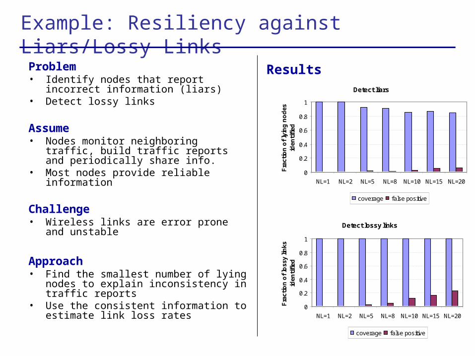
Example: Resiliency against Liars/Lossy Links
Problem• Identify nodes that report incorrect
information (liars)• Detect lossy links
Assume• Nodes monitor neighboring traffic, build
traffic reports and periodically share info.• Most nodes provide reliable information
Challenge• Wireless links are error prone and unstable
Approach• Find the smallest number of lying nodes to
explain inconsistency in traffic reports• Use the consistent information to estimate
link loss rates
Detect liars
0
0.2
0.4
0.6
0.8
1
NL=1 NL=2 NL=5 NL=8 NL=10 NL=15 NL=20
Fra
ctio
n o
f ly
ing
no
des
id
enti
fied
coverage false positive
Detect lossy links
0
0.2
0.4
0.6
0.8
1
NL=1 NL=2 NL=5 NL=8 NL=10 NL=15 NL=20
Fra
ctio
n o
f lo
ssy
links
id
enti
fied
coverage false positive
Results

Fault Diagnosis Algorithm
1. Initialization: diagnosed fault set F = { }2. Forward addition
while (diff(MeasuredPerf, SimulatedPerf(F)) > threshold) {Find a candiate fault that explains the mismatch between current and predicted performance the most, and add it to F
}
3. Backward deletionwhile (diff(MeasuredPerf, SimulatedPerf(F)) > threshold) {
Find a fault in F that explains the mismatch the least. Delete it from F if excluding it results in little change
}
4. Report F
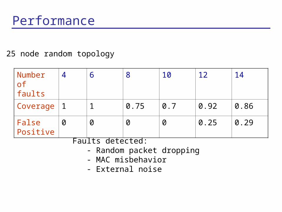
Performance
Number of faults
4 6 8 10 12 14
Coverage 1 1 0.75 0.7 0.92 0.86
False Positive
0 0 0 0 0.25 0.29
Faults detected:- Random packet dropping- MAC misbehavior- External noise
25 node random topology

What-if Analysis
Laptop computer
Laptop computer Laptop computer Laptop computer Laptop computer
Laptop computer
Laptop computer
Laptop computer
Laptop computer
Laptop computer
Laptop computer
Laptop computer
Laptop computer
Laptop computer
Laptop computer Laptop computer Laptop computer
Laptop computer Laptop computer Laptop computer
Laptop computer Laptop computer Laptop computer Laptop computer
Laptop computer Laptop computer Laptop computer Laptop computer
F1 F2 F3 F7
F8
Improvement on removing flows
Action Total Throughput (Mbps)
None 1.064
Reduce Flow 8 by ½ 1.148
Re-route Flow 8 around grid boundary 1.217
Increase power from 15 dBm to 20 dBm 0.99
Increase power from 15 dBm to 25 dBm 1.661

Mesh Visualization Module


Backup

Detection of Intentional Packet Drops
Scenario
- 49 node network
- Randomly pick nodes that drop packets
Coverage
0%20%40%60%80%
100%
r1 r2 r3 r1 r2 r3 r1 r2 r3 r1 r2 r3 r1 r2 r3
fault=1 fault=2 fault=3 fault=4 fault=5
detected faults no effect faults
False positive
0%
50%
100%
150%
200%
r1 r2 r3 r1 r2 r3 r1 r2 r3 r1 r2 r3 r1 r2 r3
fault=1 fault=2 fault=3 fault=4 fault=5