troubleshooting the cts 1300-65 · chapter 8-1 cisco telepresence system administration guide...
TRANSCRIPT
OL-21845-01
C H A P T E R 8
Troubleshooting the CTS 1300-65Revised: November 2011, OL-21845-01
ContentsYou may want to periodically test system components using the hardware and software tests available in the Cisco TelePresence System (CTS) Administration Troubleshooting window. This chapter contains information about troubleshooting CTS 1300-65 hardware and software.
Before You Begin
1. Obtain your IP address in one of the following ways:
– From the CTS Cisco Unified IP phone touch the following softkeys:
Manual > more > Info
Note If you have more options on your phone, touch the more softkey until you reach the end of the selections.
– From the Cisco TelePresence Touch 12 tap the following:
More > Status > System Status
2. Make a note of the IP address.
3. Enter the IP address in your laptop’s browser window.
4. Click Yes to accept all security connection messages.
Note You cannot perform diagnostics during an active Cisco TelePresence system call.
Proceed to the following sections to troubleshoot system components:
• Managing CTS 1300-65 Hardware Setup, page 8-2
• Managing Log Files, page 8-63
• Testing Audio, page 8-68
• Testing the Network Connection, page 8-69
• Managing Configuration Issues, page 8-69
8-1Cisco TelePresence System Administration Guide
Chapter 8 Troubleshooting the CTS 1300-65 Managing CTS 1300-65 Hardware Setup
• Initiating System Restart, page 8-70
• Troubleshooting Video Quality Settings, page 8-71
• Troubleshooting Network Cabling, page 8-72
• Where to Go Next, page 8-73
Managing CTS 1300-65 Hardware SetupYou can manage and test the following Cisco TelePresence System components:
• Configuring the CTS 1300-65 Table, page 8-2
• Managing Displays, page 8-4
• Testing Cameras, page 8-6
• Testing Speakers, page 8-48
• Testing Microphones, page 8-49
• Testing the External Presentation Display, page 8-54
• Testing Presentation Devices, page 8-55
• Testing Other Devices, page 8-60
Before You Begin
Before you begin testing and troubleshooting your system, check the system displays. All of the Cisco TelePresence System Administration interface Hardware Setup features require the use of the displays in the meeting room. Therefore, we recommend the following:
1. Verify that the displays work by using the Hardware Setup > Displays tests in this section.
2. If the displays are showing the correct images, you can proceed to testing the cameras, speakers, and microphones, as needed.
Note You must test the speakers before testing the microphones because the microphone test depends on speakers that are functioning properly. See the “Testing Speakers” section on page 8-48.
Note CTS initial setup is also performed using the Hardware Setup fields. For information on how to configure CTS for the first time, see the Cisco TelePresence System 1300-65 Assembly, Use & Care, and Field Replacement Unit Guide.
Configuring the CTS 1300-65 TableBefore you can set up the cameras in a Cisco TelePresence System 1300-65 (CTS 1300-65) conference room, the Cisco TelePresence System (CTS) software needs to know the size and shape of the table in the room. A drop-down menu is provided that allows you to specify the shape of the table in the room and where participants will be seated.
8-2Cisco TelePresence System Administration Guide
OL-21845-01
Chapter 8 Troubleshooting the CTS 1300-65 Managing CTS 1300-65 Hardware Setup
Note The CTS 1300-65 is designed to be used in any type of multipurpose room. However, to ensure that you have the best conferencing experience, Cisco recommends that you optimize your room by using the guidelines and recommendations in Cisco TelePresence System 1300-65 Room Recommendations chapter in the Cisco TelePresence System 1300-65 Assembly, First-Time Setup, and Field-Replaceable Unit Guide.
Specifying the Table Size and Shape
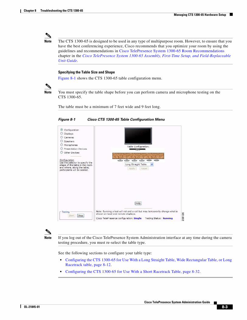
Figure 8-1 shows the CTS 1300-65 table configuration menu.
Note You must specify the table shape before you can perform camera and microphone testing on the CTS 1300-65.
The table must be a minimum of 7 feet wide and 9 feet long.
Figure 8-1 Cisco CTS 1300-65 Table Configuration Menu
Note If you log out of the Cisco TelePresence System Administration interface at any time during the camera testing procedure, you must re-select the table type.
See the following sections to configure your table type:
• Configuring the CTS 1300-65 for Use With a Long Straight Table, Wide Rectangular Table, or Long Racetrack table, page 8-12.
• Configuring the CTS 1300-65 for Use With a Short Racetrack Table, page 8-32.
8-3Cisco TelePresence System Administration Guide
OL-21845-01
Chapter 8 Troubleshooting the CTS 1300-65 Managing CTS 1300-65 Hardware Setup
Managing DisplaysA display is set up successfully when the color on the display has been adjusted for the lighting in the meeting room.
Note Each display must be adjusted individually.
Use the information in the following sections to adjust the display for your system:
• Selecting the Light Level, page 8-4
• Adjusting Your Display, page 8-5
• Troubleshooting Displays, page 8-6
• Related Information, page 8-6
Selecting the Light Level
When adjusting the images on the CTS display screens, you must take the color temperature of the ambient light in the room into consideration.
Sources of light in most rooms are produced by fluorescent fixtures or incandescent light bulbs that use tungsten filaments. Each of these light sources, and the amount of light in terms of lumens or watts, produces a different color temperature. This color temperature is sometimes expressed using terms such cool, warm, or daylight, but can be expressed more precisely in kelvins (K) as a numeric value.
The following temperatures can be selected for adjusting the image on the Cisco TelePresence display screens:
• 3500 K
• 4000/4100 K (recommended)
• 5000 K
• 6500 K
• 7500 K
Tip In many cases, the color temperature is printed on the light bulb. If you are unable to ascertain the type and color temperature of light bulbs in the meeting room, experiment with color temperature settings until the color and images on the display screen look lifelike.
Tip It is OK to try a few different color temperatures to see what looks best in the room. Remember, the Color Temperature setting only effects how the local participants see the display, it does not effect the way the room looks to remote participants.
Proceed to Adjusting Your Display.
8-4Cisco TelePresence System Administration Guide
OL-21845-01
Chapter 8 Troubleshooting the CTS 1300-65 Managing CTS 1300-65 Hardware Setup
Adjusting Your Display
To adjust a display:
Step 1 Log in to the Cisco TelePresence System Administration interface.
Step 2 Choose Troubleshooting > Hardware Setup.
Step 3 Click the Displays radio button. A test image appears on the screen.
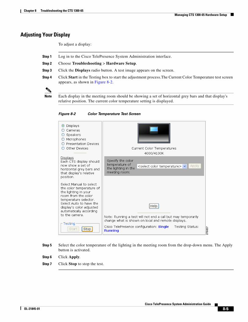
Step 4 Click Start in the Testing box to start the adjustment process.The Current Color Temperature test screen appears, as shown in Figure 8-2.
Note Each display in the meeting room should be showing a set of horizontal grey bars and that display's relative position. The current color temperature setting is displayed.
Figure 8-2 Color Temperature Test Screen
Step 5 Select the color temperature of the lighting in the meeting room from the drop-down menu. The Apply button is activated.
Step 6 Click Apply.
Step 7 Click Stop to stop the test.
8-5Cisco TelePresence System Administration Guide
OL-21845-01
Chapter 8 Troubleshooting the CTS 1300-65 Managing CTS 1300-65 Hardware Setup
Troubleshooting Displays
Use the information in Table 8-1 to troubleshoot problems with the images on the displays.
Related Information
• For more information about setting up and testing displays, see the Cisco TelePresence System 1300-65 Assembly, Use & Care, and Field Replacement Unit Guide.
• For more system troubleshooting information, see the Cisco TelePresence System Troubleshooting Guide on Cisco.com.
Testing CamerasThe cameras are set up successfully when images are centered and in focus on the display screens and the white balance has been configured. The hardware setup software provides a camera Auto Adjust feature and a way to use targets to fine-tune the camera’s focus.
Use the information in the following sections to test and troubleshoot the camera for your system:
• Testing the CTS 1300-65 Cameras, page 8-7
• Configuring the CTS 1300-65 for Use With a Conference Room Table, page 8-11
• Arranging the Seat Alignment Guides, page 8-44
• Understanding Camera Setup Choices for Room Lighting, page 8-46
• Troubleshooting Cameras, page 8-46
• Related Information, page 8-47
Note The camera cover comes off. It should be removed and left off until these procedures are complete.
Table 8-1 Troubleshooting Displays
Problem Possible Cause Action
No image. • Power cable is not plugged in.
• Power switch on the back of the display is off.
Check power connections and switches on each display.
The display has no image when you are between calls.
No image expected. Enable a display test from the Web user interface to place the displays in test mode.
Video cable is not connected. Contact Cisco technical support if you are certain that the cabling is correct and power is applied to the system, but no image is seen on the display.
See the Routing Power and Signal Cables section in the Cisco TelePresence System 1300-65 Assembly, Use & Care, and Field Replacement Unit Guide.
8-6Cisco TelePresence System Administration Guide
OL-21845-01
Chapter 8 Troubleshooting the CTS 1300-65 Managing CTS 1300-65 Hardware Setup
Testing the CTS 1300-65 Cameras
The CTS 1300-65 supports three cameras and various room configurations and table types. Use the procedures in this section to troubleshoot the cameras depending on your table type.
Note You must first configure the table size before you can test the camera. See the “Configuring the CTS 1300-65 Table” section on page 8-2. For more information about the supported table types, see the Supported Table Types and Minimum Room Dimensions section of the Cisco TelePresence System 1300-65 Assembly, First-Time Setup, and Field-Replaceable Unit Guide.
Note If you log out of the Cisco TelePresence System Administration interface at any time during the camera testing procedure, you must re-select the table type. To select the correct table type, complete the steps in the “Positioning the Table and Starting the Calibration Procedure” section on page 8-12.
Use the information in the following sections to set up the CTS 1300-65 camera for testing:
• Removing the Camera Cover and Leveling the Cameras, page 8-7
• Attaching the Large Camera Target to the Easel, page 8-10
• Configuring the CTS 1300-65 for Use With a Long Straight Table, Wide Rectangular Table, or Long Racetrack table, page 8-12
• Configuring the CTS 1300-65 for Use With a Short Racetrack Table, page 8-32
• Saving Your Settings, page 8-43
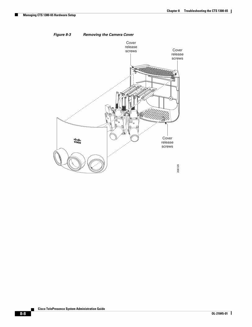
Removing the Camera Cover and Leveling the Cameras
The camera cluster must be perfectly level for you to properly test the camera. To remove the camera cover and level the camera:
Step 1 Remove the camera cover by removing the four black plastic screws on the top and bottom of the camera assembly, as shown in Figure 8-3.
8-7Cisco TelePresence System Administration Guide
OL-21845-01
Chapter 8 Troubleshooting the CTS 1300-65 Managing CTS 1300-65 Hardware Setup
Figure 8-3 Removing the Camera Cover
2061
29
Coverreleasescrews
Coverreleasescrews
Coverreleasescrews
8-8Cisco TelePresence System Administration Guide
OL-21845-01
Chapter 8 Troubleshooting the CTS 1300-65 Managing CTS 1300-65 Hardware Setup
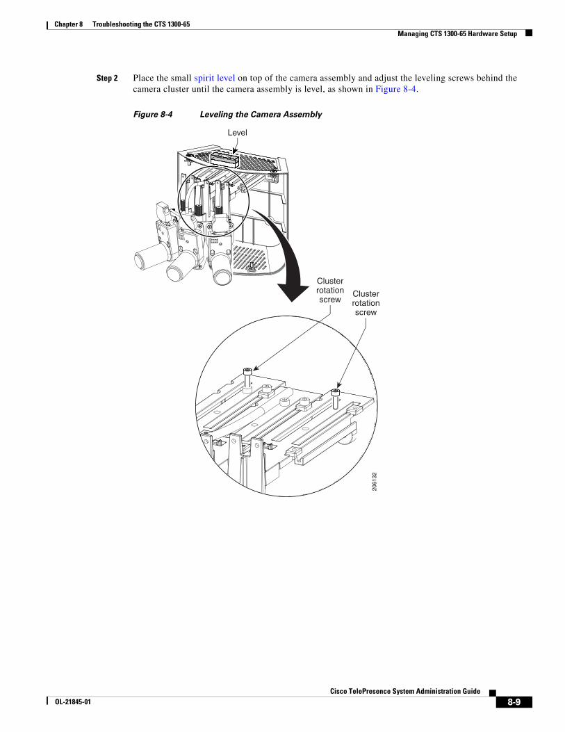
Step 2 Place the small spirit level on top of the camera assembly and adjust the leveling screws behind the camera cluster until the camera assembly is level, as shown in Figure 8-4.
Figure 8-4 Leveling the Camera Assembly
Clusterrotationscrew
Clusterrotationscrew
2061
32
Level
8-9Cisco TelePresence System Administration Guide
OL-21845-01
Chapter 8 Troubleshooting the CTS 1300-65 Managing CTS 1300-65 Hardware Setup
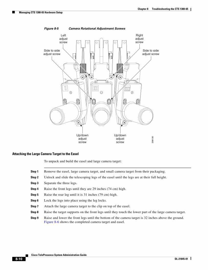
Figure 8-5 Camera Rotational Adjustment Screws
Attaching the Large Camera Target to the Easel
To unpack and build the easel and large camera target:
Step 1 Remove the easel, large camera target, and small camera target from their packaging.
Step 2 Unlock and slide the telescoping legs of the easel until the legs are at their full height.
Step 3 Separate the three legs.
Step 4 Raise the front legs until they are 29 inches (74 cm) high.
Step 5 Raise the rear leg until it is 31 inches (79 cm) high.
Step 6 Lock the legs into place using the leg locks.
Step 7 Attach the large camera target to the clip on top of the easel.
Step 8 Raise the target supports on the front legs until they touch the lower part of the large camera target.
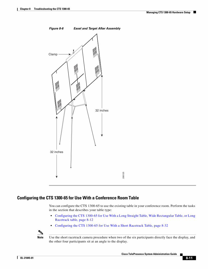
Step 9 Raise and lower the front legs until the bottom of the camera target is 32 inches above the ground. Figure 8-6 shows the completed camera target and easel.
Rightadjustscrew
Leftadjustscrew
Up/downadjustscrew
Side to sideadjust screw
Side to sideadjust screw
Up/downadjustscrew 20
6130
8-10Cisco TelePresence System Administration Guide
OL-21845-01
Chapter 8 Troubleshooting the CTS 1300-65 Managing CTS 1300-65 Hardware Setup
Figure 8-6 Easel and Target After Assembly
Configuring the CTS 1300-65 for Use With a Conference Room Table
You can configure the CTS 1300-65 to use the existing table in your conference room. Perform the tasks in the section that describes your table type:
• Configuring the CTS 1300-65 for Use With a Long Straight Table, Wide Rectangular Table, or Long Racetrack table, page 8-12
• Configuring the CTS 1300-65 for Use With a Short Racetrack Table, page 8-32
Note Use the short racetrack camera procedure when two of the six participants directly face the display, and the other four participants sit at an angle to the display.
2061
25
Clamp
32 inches
32 inches
8-11Cisco TelePresence System Administration Guide
OL-21845-01
Chapter 8 Troubleshooting the CTS 1300-65 Managing CTS 1300-65 Hardware Setup
If four or more of the six participants directly face the display, follow the procedure in the “Configuring the CTS 1300-65 for Use With a Long Straight Table, Wide Rectangular Table, or Long Racetrack table” section on page 8-12
Configuring the CTS 1300-65 for Use With a Long Straight Table, Wide Rectangular Table, or Long Racetrack table
Note If you log out of the Cisco TelePresence System Administration interface at any time during the camera testing procedure, you must re-select the table type. To select the correct table type, complete the steps in the “Positioning the Table and Starting the Calibration Procedure” section on page 8-12.
This section includes the procedures you perform to configure the CTS 1300-65 software and cameras for use with a room that has a long straight table, wide rectangular table, or wide racetrack table, and includes the following topics:
• Positioning the Table and Starting the Calibration Procedure, page 8-12
• Calibrating the Center Camera, page 8-19
• Calibrating the Right Camera, page 8-23
• Calibrating the Left Camera, page 8-25
• Focusing the Center Camera, page 8-27
• Focusing the Right Camera, page 8-29
• Focusing the Left Camera, page 8-29
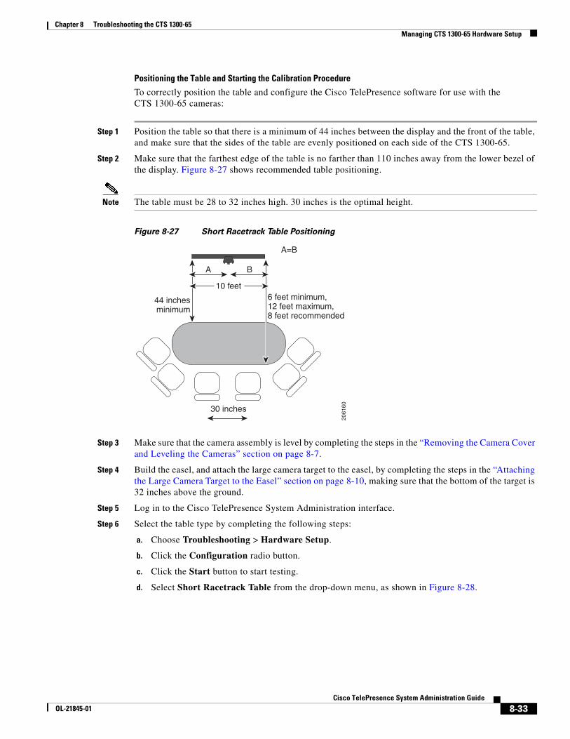
Positioning the Table and Starting the Calibration Procedure
To correctly position the table and configure the Cisco TelePresence software for use with the CTS 1300-65 cameras:
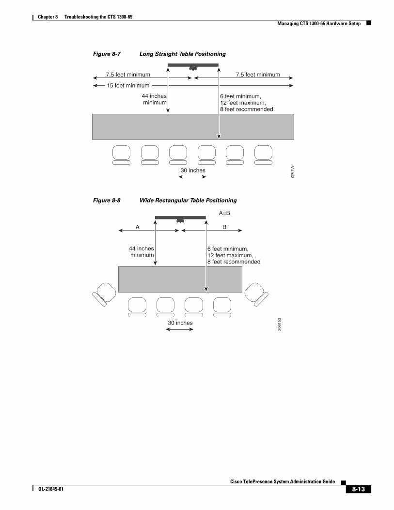
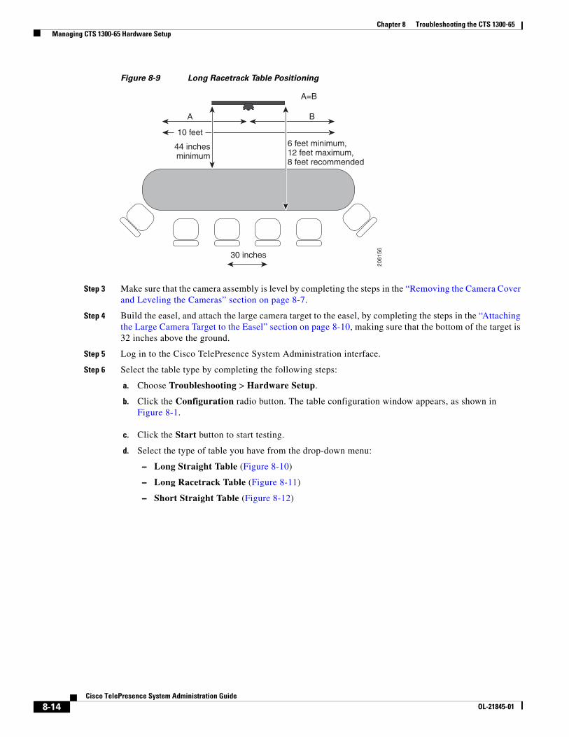
Step 1 Position the table so that there is a minimum of 44 inches between the display and the front of the table, and make sure that the sides of the table are evenly positioned on each side of the CTS 1300-65, as shown in the following examples:
• Long, straight table, Figure 8-7
• Wide rectangular table, Figure 8-8
• Long racetrack table, Figure 8-9
Step 2 Make sure that the farthest edge of the table is no farther than 110 inches away from the lower bezel of the display.
Note The table must be 28 to 32 inches high. 30 inches is the optimal height.
8-12Cisco TelePresence System Administration Guide
OL-21845-01
Chapter 8 Troubleshooting the CTS 1300-65 Managing CTS 1300-65 Hardware Setup
Figure 8-7 Long Straight Table Positioning
Figure 8-8 Wide Rectangular Table Positioning
15 feet minimum
7.5 feet minimum 7.5 feet minimum
30 inches
44 inchesminimum
6 feet minimum,12 feet maximum,8 feet recommended
2061
39
A B
A=B
30 inches
44 inchesminimum
6 feet minimum,12 feet maximum,8 feet recommended
2061
50
8-13Cisco TelePresence System Administration Guide
OL-21845-01
Chapter 8 Troubleshooting the CTS 1300-65 Managing CTS 1300-65 Hardware Setup
Figure 8-9 Long Racetrack Table Positioning
Step 3 Make sure that the camera assembly is level by completing the steps in the “Removing the Camera Cover and Leveling the Cameras” section on page 8-7.
Step 4 Build the easel, and attach the large camera target to the easel, by completing the steps in the “Attaching the Large Camera Target to the Easel” section on page 8-10, making sure that the bottom of the target is 32 inches above the ground.
Step 5 Log in to the Cisco TelePresence System Administration interface.
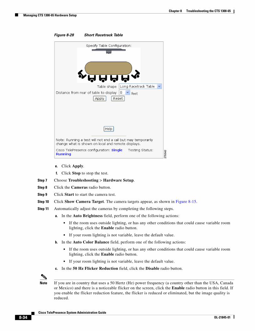
Step 6 Select the table type by completing the following steps:
a. Choose Troubleshooting > Hardware Setup.
b. Click the Configuration radio button. The table configuration window appears, as shown in Figure 8-1.
c. Click the Start button to start testing.
d. Select the type of table you have from the drop-down menu:
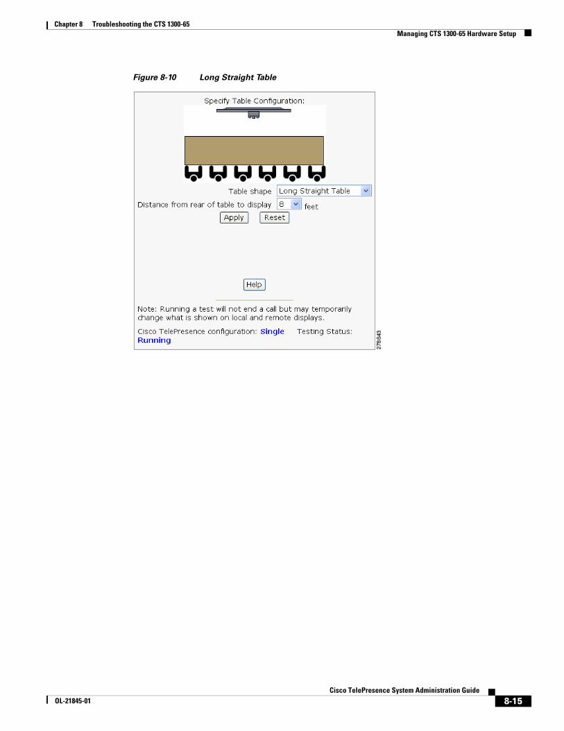
– Long Straight Table (Figure 8-10)
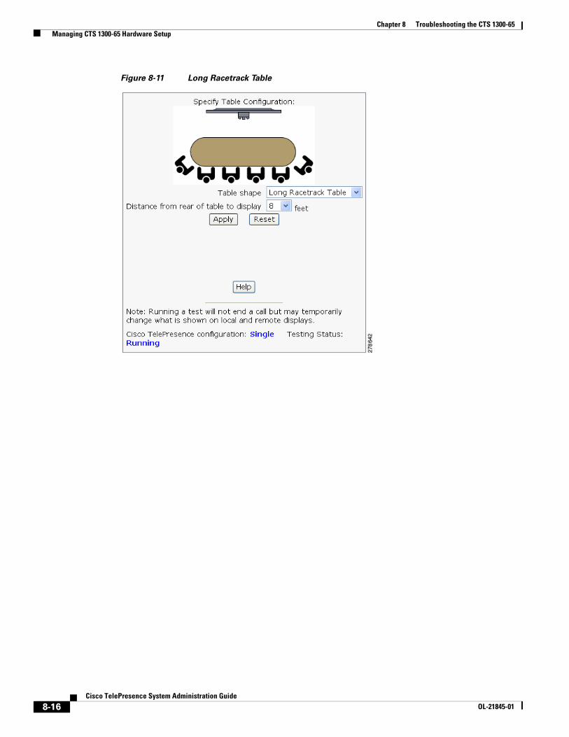
– Long Racetrack Table (Figure 8-11)
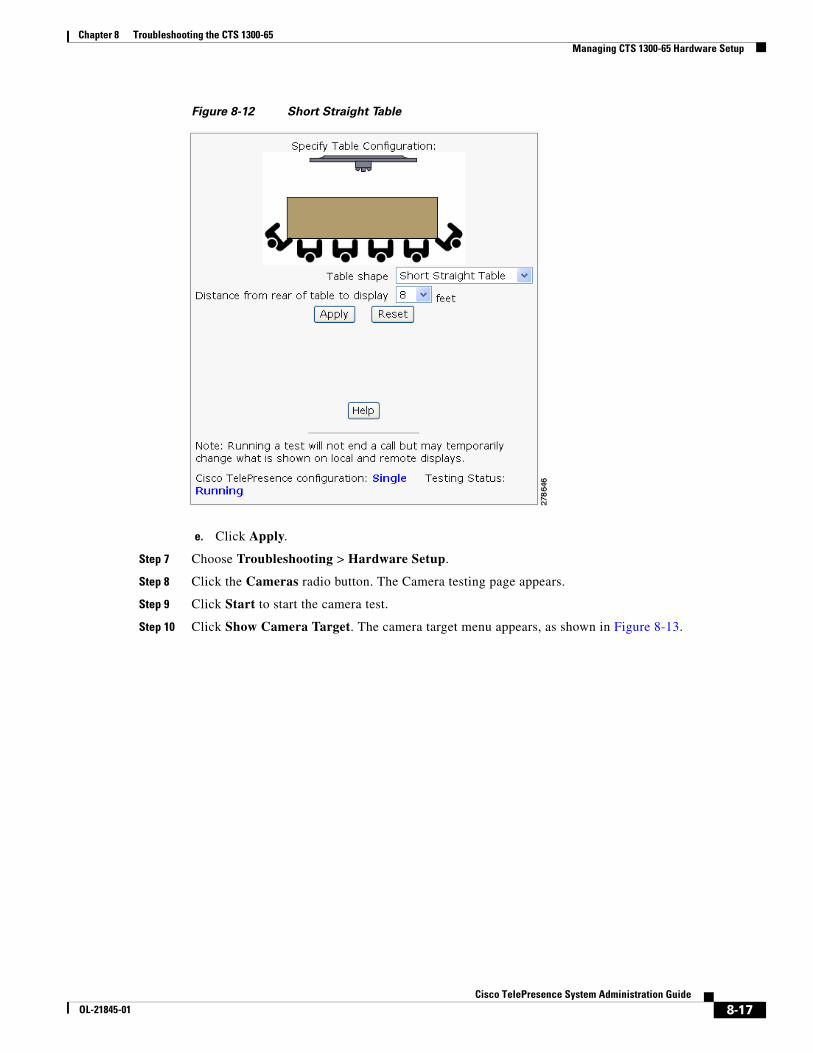
– Short Straight Table (Figure 8-12)
10 feet
A B
30 inches
44 inchesminimum
6 feet minimum,12 feet maximum,8 feet recommended
2061
56
A=B
8-14Cisco TelePresence System Administration Guide
OL-21845-01
Chapter 8 Troubleshooting the CTS 1300-65 Managing CTS 1300-65 Hardware Setup
Figure 8-10 Long Straight Table
8-15Cisco TelePresence System Administration Guide
OL-21845-01
Chapter 8 Troubleshooting the CTS 1300-65 Managing CTS 1300-65 Hardware Setup
Figure 8-11 Long Racetrack Table
8-16Cisco TelePresence System Administration Guide
OL-21845-01
Chapter 8 Troubleshooting the CTS 1300-65 Managing CTS 1300-65 Hardware Setup
Figure 8-12 Short Straight Table
e. Click Apply.
Step 7 Choose Troubleshooting > Hardware Setup.
Step 8 Click the Cameras radio button. The Camera testing page appears.
Step 9 Click Start to start the camera test.
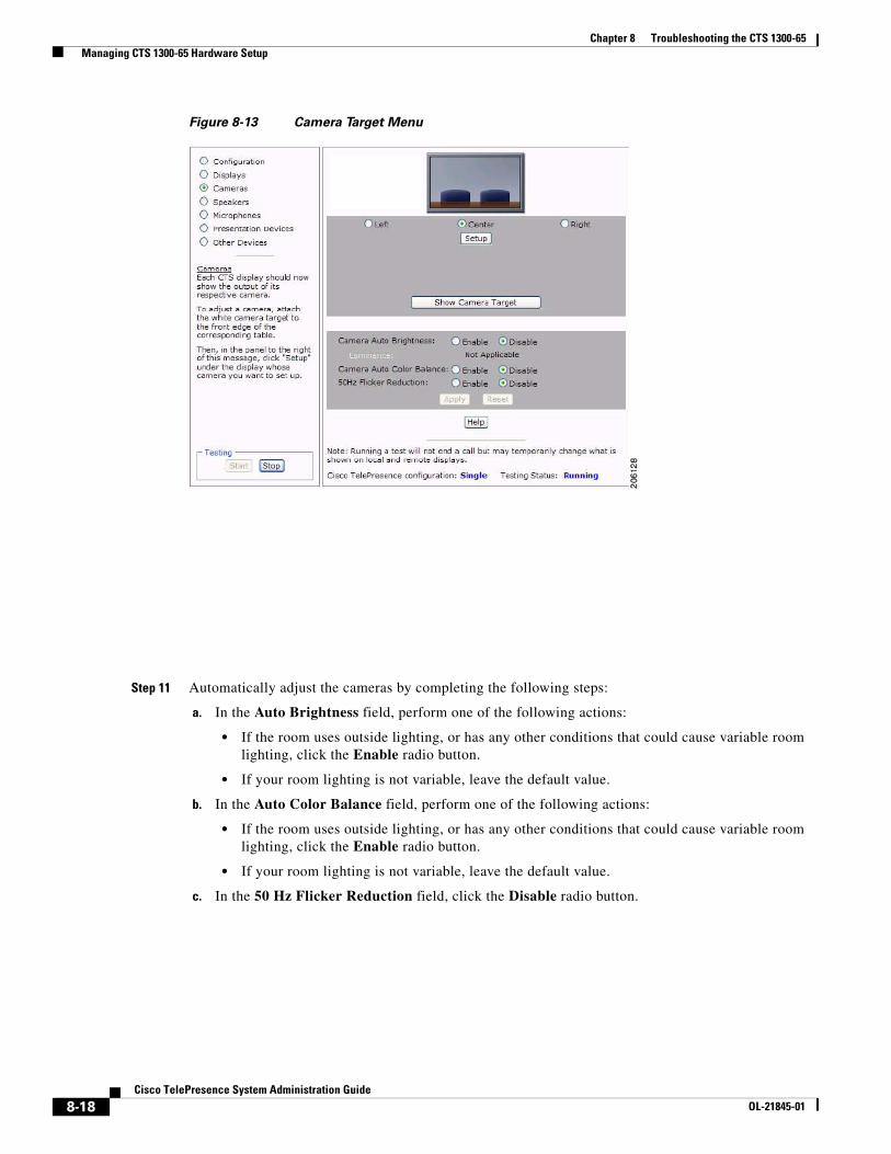
Step 10 Click Show Camera Target. The camera target menu appears, as shown in Figure 8-13.
8-17Cisco TelePresence System Administration Guide
OL-21845-01
Chapter 8 Troubleshooting the CTS 1300-65 Managing CTS 1300-65 Hardware Setup
Figure 8-13 Camera Target Menu
Step 11 Automatically adjust the cameras by completing the following steps:
a. In the Auto Brightness field, perform one of the following actions:
• If the room uses outside lighting, or has any other conditions that could cause variable room lighting, click the Enable radio button.
• If your room lighting is not variable, leave the default value.
b. In the Auto Color Balance field, perform one of the following actions:
• If the room uses outside lighting, or has any other conditions that could cause variable room lighting, click the Enable radio button.
• If your room lighting is not variable, leave the default value.
c. In the 50 Hz Flicker Reduction field, click the Disable radio button.
8-18Cisco TelePresence System Administration Guide
OL-21845-01
Chapter 8 Troubleshooting the CTS 1300-65 Managing CTS 1300-65 Hardware Setup
Note If you are in country that uses a 50 Hertz (Hz) power frequency (a country other than the USA, Canada or Mexico) and there is a noticeable flicker on the screen, click the Enable radio button in this field. If you enable the flicker reduction feature, the flicker is reduced or eliminated, but the image quality is reduced.
To eliminate the flicker at its source, you can use an electronic ballast instead of a magnet ballast for the fluorescent lights at your installation. After you change the ballast for the fluorescent lights, you can click the Disable radio button in the 50 Hz Flicker Reduction field.
Step 12 Click Apply to apply your changes.
Calibrating the Center Camera
To adjust the zoom and initial focus for the center camera:
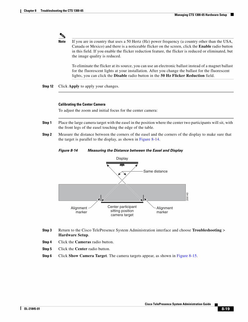
Step 1 Place the large camera target with the easel in the position where the center two participants will sit, with the front legs of the easel touching the edge of the table.
Step 2 Measure the distance between the corners of the easel and the corners of the display to make sure that the target is parallel to the display, as shown in Figure 8-14.
Figure 8-14 Measuring the Distance between the Easel and Display
Step 3 Return to the Cisco TelePresence System Administration interface and choose Troubleshooting > Hardware Setup.
Step 4 Click the Cameras radio button.
Step 5 Click the Center radio button.
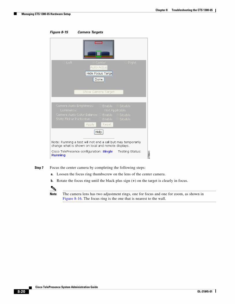
Step 6 Click Show Camera Target. The camera targets appear, as shown in Figure 8-15.
Display
Same distance
Center participantsitting positioncamera target
2061
40
Alignmentmarker
Alignmentmarker
8-19Cisco TelePresence System Administration Guide
OL-21845-01
Chapter 8 Troubleshooting the CTS 1300-65 Managing CTS 1300-65 Hardware Setup
Figure 8-15 Camera Targets
Step 7 Focus the center camera by completing the following steps:
a. Loosen the focus ring thumbscrew on the lens of the center camera.
b. Rotate the focus ring until the black plus sign (+) on the target is clearly in focus.
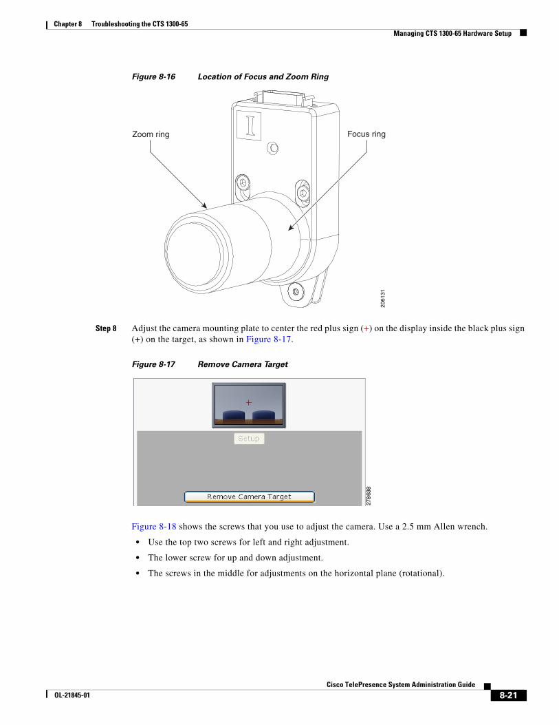
Note The camera lens has two adjustment rings, one for focus and one for zoom, as shown in Figure 8-16. The focus ring is the one that is nearest to the wall.
8-20Cisco TelePresence System Administration Guide
OL-21845-01
Chapter 8 Troubleshooting the CTS 1300-65 Managing CTS 1300-65 Hardware Setup
Figure 8-16 Location of Focus and Zoom Ring
Step 8 Adjust the camera mounting plate to center the red plus sign (+) on the display inside the black plus sign (+) on the target, as shown in Figure 8-17.
Figure 8-17 Remove Camera Target
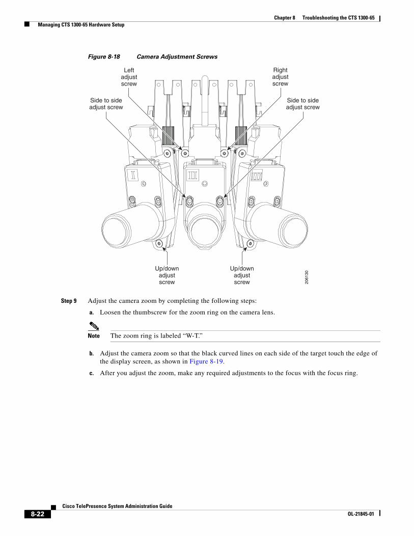
Figure 8-18 shows the screws that you use to adjust the camera. Use a 2.5 mm Allen wrench.
• Use the top two screws for left and right adjustment.
• The lower screw for up and down adjustment.
• The screws in the middle for adjustments on the horizontal plane (rotational).
Focus ringZoom ring
2061
31
8-21Cisco TelePresence System Administration Guide
OL-21845-01
Chapter 8 Troubleshooting the CTS 1300-65 Managing CTS 1300-65 Hardware Setup
Figure 8-18 Camera Adjustment Screws
Step 9 Adjust the camera zoom by completing the following steps:
a. Loosen the thumbscrew for the zoom ring on the camera lens.
Note The zoom ring is labeled “W-T.”
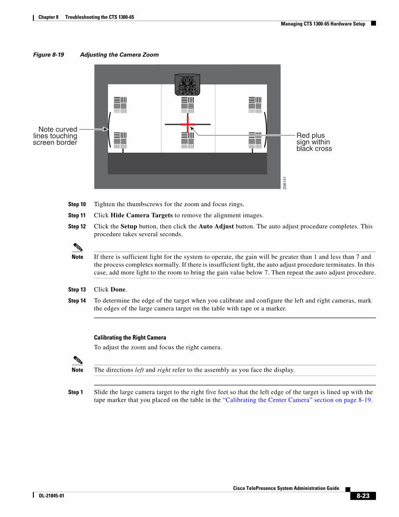
b. Adjust the camera zoom so that the black curved lines on each side of the target touch the edge of the display screen, as shown in Figure 8-19.
c. After you adjust the zoom, make any required adjustments to the focus with the focus ring.
Rightadjustscrew
Leftadjustscrew
Up/downadjustscrew
Side to sideadjust screw
Side to sideadjust screw
Up/downadjustscrew 20
6130
8-22Cisco TelePresence System Administration Guide
OL-21845-01
Chapter 8 Troubleshooting the CTS 1300-65 Managing CTS 1300-65 Hardware Setup
Figure 8-19 Adjusting the Camera Zoom
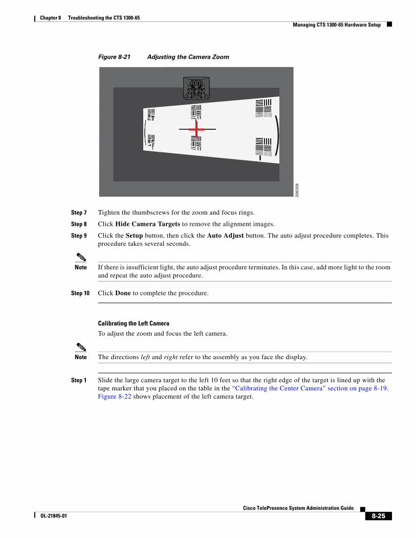
Step 10 Tighten the thumbscrews for the zoom and focus rings.
Step 11 Click Hide Camera Targets to remove the alignment images.
Step 12 Click the Setup button, then click the Auto Adjust button. The auto adjust procedure completes. This procedure takes several seconds.
Note If there is sufficient light for the system to operate, the gain will be greater than 1 and less than 7 and the process completes normally. If there is insufficient light, the auto adjust procedure terminates. In this case, add more light to the room to bring the gain value below 7. Then repeat the auto adjust procedure.
Step 13 Click Done.
Step 14 To determine the edge of the target when you calibrate and configure the left and right cameras, mark the edges of the large camera target on the table with tape or a marker.
Calibrating the Right Camera
To adjust the zoom and focus the right camera.
Note The directions left and right refer to the assembly as you face the display.
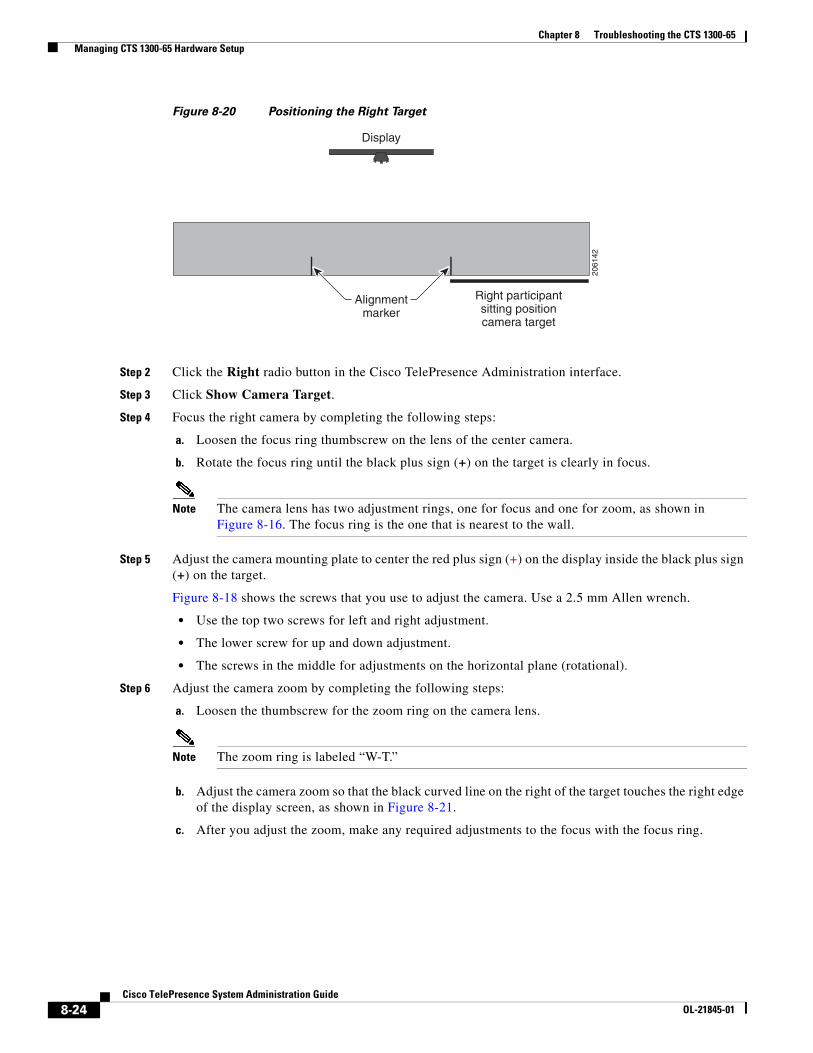
Step 1 Slide the large camera target to the right five feet so that the left edge of the target is lined up with the tape marker that you placed on the table in the “Calibrating the Center Camera” section on page 8-19.
2061
41
Red plussign withinblack cross
Note curvedlines touchingscreen border
8-23Cisco TelePresence System Administration Guide
OL-21845-01
Chapter 8 Troubleshooting the CTS 1300-65 Managing CTS 1300-65 Hardware Setup
Figure 8-20 Positioning the Right Target
Step 2 Click the Right radio button in the Cisco TelePresence Administration interface.
Step 3 Click Show Camera Target.
Step 4 Focus the right camera by completing the following steps:
a. Loosen the focus ring thumbscrew on the lens of the center camera.
b. Rotate the focus ring until the black plus sign (+) on the target is clearly in focus.
Note The camera lens has two adjustment rings, one for focus and one for zoom, as shown in Figure 8-16. The focus ring is the one that is nearest to the wall.
Step 5 Adjust the camera mounting plate to center the red plus sign (+) on the display inside the black plus sign (+) on the target.
Figure 8-18 shows the screws that you use to adjust the camera. Use a 2.5 mm Allen wrench.
• Use the top two screws for left and right adjustment.
• The lower screw for up and down adjustment.
• The screws in the middle for adjustments on the horizontal plane (rotational).
Step 6 Adjust the camera zoom by completing the following steps:
a. Loosen the thumbscrew for the zoom ring on the camera lens.
Note The zoom ring is labeled “W-T.”
b. Adjust the camera zoom so that the black curved line on the right of the target touches the right edge of the display screen, as shown in Figure 8-21.
c. After you adjust the zoom, make any required adjustments to the focus with the focus ring.
Display
Right participantsitting positioncamera target
2061
42
Alignmentmarker
8-24Cisco TelePresence System Administration Guide
OL-21845-01
Chapter 8 Troubleshooting the CTS 1300-65 Managing CTS 1300-65 Hardware Setup
Figure 8-21 Adjusting the Camera Zoom
Step 7 Tighten the thumbscrews for the zoom and focus rings.
Step 8 Click Hide Camera Targets to remove the alignment images.
Step 9 Click the Setup button, then click the Auto Adjust button. The auto adjust procedure completes. This procedure takes several seconds.
Note If there is insufficient light, the auto adjust procedure terminates. In this case, add more light to the room and repeat the auto adjust procedure.
Step 10 Click Done to complete the procedure.
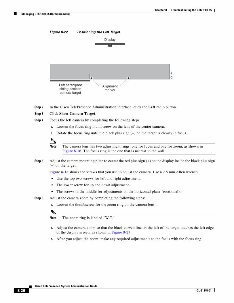
Calibrating the Left Camera
To adjust the zoom and focus the left camera.
Note The directions left and right refer to the assembly as you face the display.
Step 1 Slide the large camera target to the left 10 feet so that the right edge of the target is lined up with the tape marker that you placed on the table in the “Calibrating the Center Camera” section on page 8-19. Figure 8-22 shows placement of the left camera target.
2063
58
8-25Cisco TelePresence System Administration Guide
OL-21845-01
Chapter 8 Troubleshooting the CTS 1300-65 Managing CTS 1300-65 Hardware Setup
Figure 8-22 Positioning the Left Target
Step 2 In the Cisco TelePresence Administration interface, click the Left radio button.
Step 3 Click Show Camera Target.
Step 4 Focus the left camera by completing the following steps:
a. Loosen the focus ring thumbscrew on the lens of the center camera.
b. Rotate the focus ring until the black plus sign (+) on the target is clearly in focus.
Note The camera lens has two adjustment rings, one for focus and one for zoom, as shown in Figure 8-16. The focus ring is the one that is nearest to the wall.
Step 5 Adjust the camera mounting plate to center the red plus sign (+) on the display inside the black plus sign(+) on the target.
Figure 8-18 shows the screws that you use to adjust the camera. Use a 2.5 mm Allen wrench.
• Use the top two screws for left and right adjustment.
• The lower screw for up and down adjustment.
• The screws in the middle for adjustments on the horizontal plane (rotational).
Step 6 Adjust the camera zoom by completing the following steps:
a. Loosen the thumbscrew for the zoom ring on the camera lens.
Note The zoom ring is labeled “W-T.”
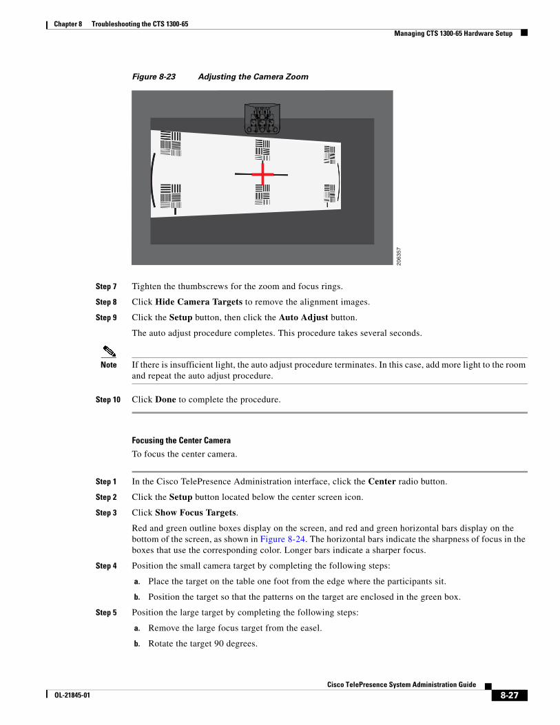
b. Adjust the camera zoom so that the black curved line on the left of the target touches the left edge of the display screen, as shown in Figure 8-23.
c. After you adjust the zoom, make any required adjustments to the focus with the focus ring.
Left participantsitting positioncamera target
Display
2061
44
Alignmentmarker
8-26Cisco TelePresence System Administration Guide
OL-21845-01
Chapter 8 Troubleshooting the CTS 1300-65 Managing CTS 1300-65 Hardware Setup
Figure 8-23 Adjusting the Camera Zoom
Step 7 Tighten the thumbscrews for the zoom and focus rings.
Step 8 Click Hide Camera Targets to remove the alignment images.
Step 9 Click the Setup button, then click the Auto Adjust button.
The auto adjust procedure completes. This procedure takes several seconds.
Note If there is insufficient light, the auto adjust procedure terminates. In this case, add more light to the room and repeat the auto adjust procedure.
Step 10 Click Done to complete the procedure.
Focusing the Center Camera
To focus the center camera.
Step 1 In the Cisco TelePresence Administration interface, click the Center radio button.
Step 2 Click the Setup button located below the center screen icon.
Step 3 Click Show Focus Targets.
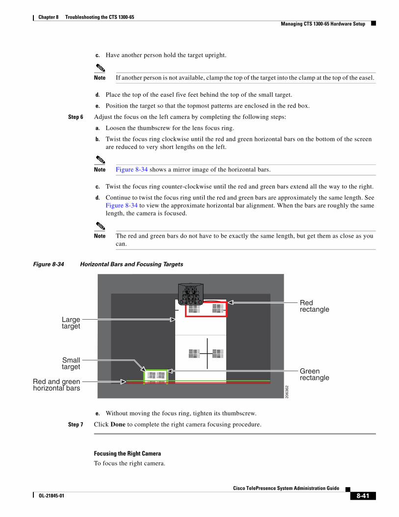
Red and green outline boxes display on the screen, and red and green horizontal bars display on the bottom of the screen, as shown in Figure 8-24. The horizontal bars indicate the sharpness of focus in the boxes that use the corresponding color. Longer bars indicate a sharper focus.
Step 4 Position the small camera target by completing the following steps:
a. Place the target on the table one foot from the edge where the participants sit.
b. Position the target so that the patterns on the target are enclosed in the green box.
Step 5 Position the large target by completing the following steps:
a. Remove the large focus target from the easel.
b. Rotate the target 90 degrees.
2063
57
8-27Cisco TelePresence System Administration Guide
OL-21845-01
Chapter 8 Troubleshooting the CTS 1300-65 Managing CTS 1300-65 Hardware Setup
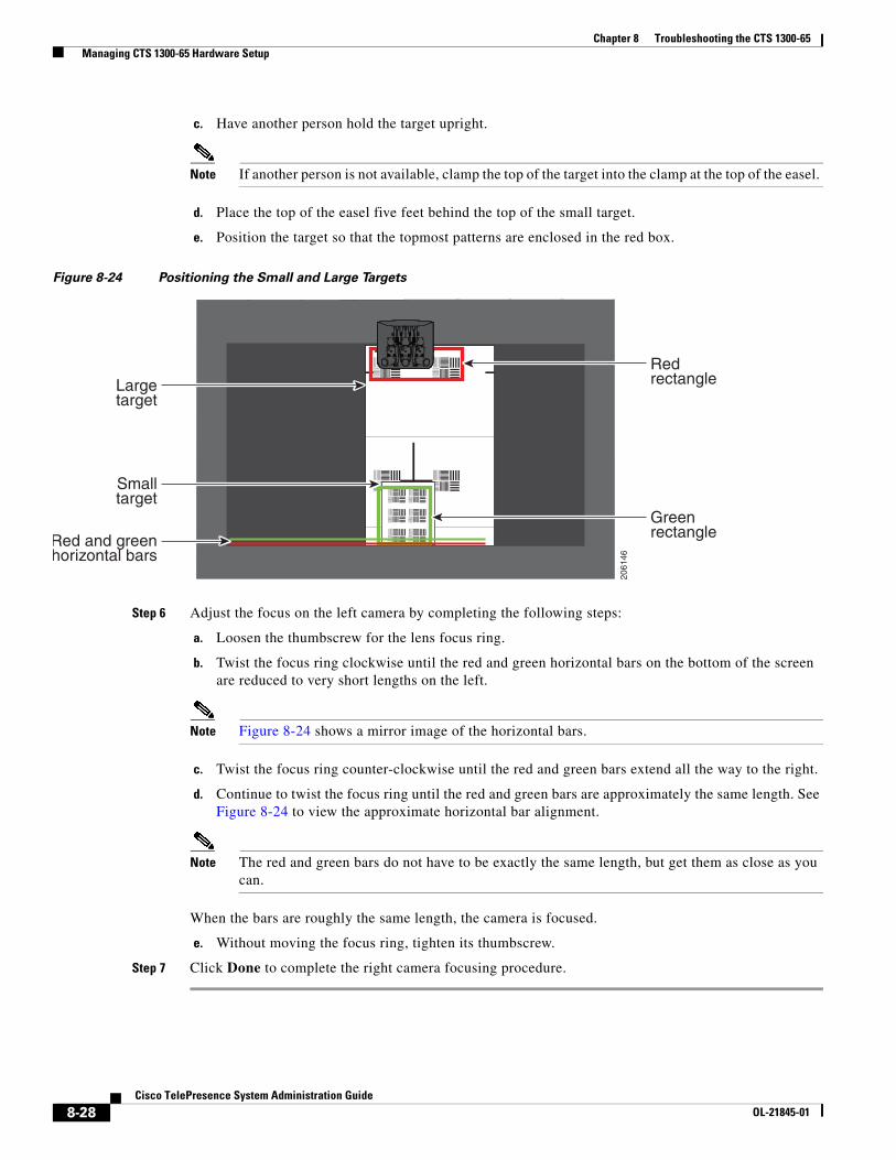
c. Have another person hold the target upright.
Note If another person is not available, clamp the top of the target into the clamp at the top of the easel.
d. Place the top of the easel five feet behind the top of the small target.
e. Position the target so that the topmost patterns are enclosed in the red box.
Figure 8-24 Positioning the Small and Large Targets
Step 6 Adjust the focus on the left camera by completing the following steps:
a. Loosen the thumbscrew for the lens focus ring.
b. Twist the focus ring clockwise until the red and green horizontal bars on the bottom of the screen are reduced to very short lengths on the left.
Note Figure 8-24 shows a mirror image of the horizontal bars.
c. Twist the focus ring counter-clockwise until the red and green bars extend all the way to the right.
d. Continue to twist the focus ring until the red and green bars are approximately the same length. See Figure 8-24 to view the approximate horizontal bar alignment.
Note The red and green bars do not have to be exactly the same length, but get them as close as you can.
When the bars are roughly the same length, the camera is focused.
e. Without moving the focus ring, tighten its thumbscrew.
Step 7 Click Done to complete the right camera focusing procedure.
2061
46
Redrectangle
Greenrectangle
Largetarget
Smalltarget
Red and greenhorizontal bars
8-28Cisco TelePresence System Administration Guide
OL-21845-01
Chapter 8 Troubleshooting the CTS 1300-65 Managing CTS 1300-65 Hardware Setup
Focusing the Right Camera
To focus the right camera:
Step 1 In the Cisco TelePresence Administration interface, click the Right radio button.
Step 2 Click the Setup button that is located below the center screen icon.
Step 3 Click Show Focus Targets.
Step 4 Position the small camera target by completing the following steps:
a. Place the target on the table one foot from the edge where the participants sit.
b. Position the target so that the patterns on the target are enclosed in the green box.
Step 5 Position the large target by completing the following steps:
a. Remove the large focus target from the easel.
b. Rotate the target 90 degrees.
c. Have another person hold the target upright.
Note If another person is not available, clamp the top of the target into the clamp at the top of the easel.
d. Place the top of the easel five feet behind the top of the small target.
e. Position the target so that the topmost patterns are enclosed in the red box, as shown in Figure 8-24.
Step 6 Adjust the camera focus by completing the following steps:
a. Loosen the thumbscrew for the lens focus ring.
b. Twist the focus ring clockwise until the red and green horizontal bars on the bottom of the screen are reduced to very short lengths on the left.
Note Figure 8-24 shows a mirror image of the horizontal bars.
c. Twist the focus ring counter-clockwise until the red and green bars extend all the way to the right.
d. Continue to twist the focus ring until the red and green bars are approximately the same length. See Figure 8-24 to view the approximate horizontal bar alignment. When the bars are roughly the same length, the camera is focused.
Note The red and green bars do not have to be exactly the same length, but get them as close as you can.
e. Without moving the focus ring, tighten its thumbscrew.
Step 7 Click Done to complete the right camera focusing procedure.
Focusing the Left Camera
To focus the left camera:
Step 1 In the Cisco TelePresence Administration interface, click the Right radio button.
Step 2 Click the Setup button that is located below the center screen icon.
8-29Cisco TelePresence System Administration Guide
OL-21845-01
Chapter 8 Troubleshooting the CTS 1300-65 Managing CTS 1300-65 Hardware Setup
Step 3 Click Show Focus Targets.
Step 4 Position the small camera target by completing the following steps:
a. Place the target on the table one foot from the edge where the participants sit.
b. Position the target so that the patterns on the target are enclosed in the green box.
Step 5 Position the large target by completing the following steps:
a. Remove the large focus target from the easel.
b. Rotate the target 90 degrees.
c. Have another person hold the target upright.
Note If another person is not available, clamp the top of the target into the clamp at the top of the easel.
d. Place the top of the easel five feet behind the top of the small target.
e. Position the target so that the topmost patterns are enclosed in the red box, as shown in Figure 8-24.
Step 6 Adjust the focus on the left camera by completing the following steps:
a. Loosen the thumbscrew for the lens focus ring.
b. Twist the focus ring clockwise until the red and green horizontal bars on the bottom of the screen are reduced to very short lengths on the left.
Note Figure 8-24 shows a mirror image of the horizontal bars.
c. Twist the focus ring counter-clockwise until the red and green bars extend all the way to the right.
d. Continue to twist the focus ring until the red and green bars are approximately the same length. See Figure 8-24 to view the approximate horizontal bar alignment. When the bars are roughly the same length, the camera is focused.
Note The red and green bars do not have to be exactly the same length, but get them as close as you can.
e. Without moving the focus ring, tighten its thumbscrew.
Step 7 Click Done to complete the right camera focusing procedure.
Replacing the Camera Cover
To replace the camera cover:
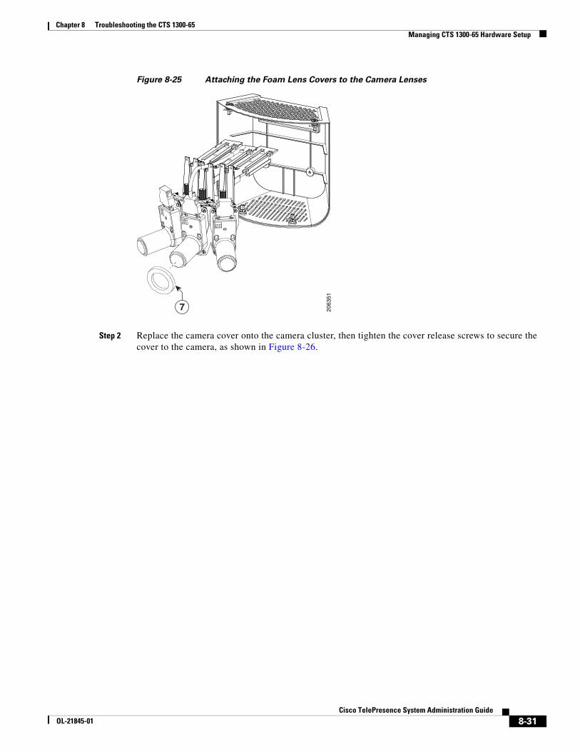
Step 1 Place the foam lens covers onto the camera lenses, as shown in Figure 8-25.
8-30Cisco TelePresence System Administration Guide
OL-21845-01
Chapter 8 Troubleshooting the CTS 1300-65 Managing CTS 1300-65 Hardware Setup
Figure 8-25 Attaching the Foam Lens Covers to the Camera Lenses
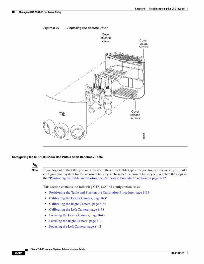
Step 2 Replace the camera cover onto the camera cluster, then tighten the cover release screws to secure the cover to the camera, as shown in Figure 8-26.
2063
51
7
8-31Cisco TelePresence System Administration Guide
OL-21845-01
Chapter 8 Troubleshooting the CTS 1300-65 Managing CTS 1300-65 Hardware Setup
Figure 8-26 Replacing the Camera Cover
Configuring the CTS 1300-65 for Use With a Short Racetrack Table
Note If you log out of the GUI, you must re-select the correct table type after you log in; otherwise, you could configure your system for the incorrect table type. To select the correct table type, complete the steps in the “Positioning the Table and Starting the Calibration Procedure” section on page 8-12.
This section contains the following CTS 1300-65 configuration tasks:
• Positioning the Table and Starting the Calibration Procedure, page 8-33
• Calibrating the Center Camera, page 8-35
• Calibrating the Right Camera, page 8-36
• Calibrating the Left Camera, page 8-38
• Focusing the Center Camera, page 8-40
• Focusing the Right Camera, page 8-41
• Focusing the Left Camera, page 8-42
2061
29
Coverreleasescrews
Coverreleasescrews
Coverreleasescrews
8-32Cisco TelePresence System Administration Guide
OL-21845-01
Chapter 8 Troubleshooting the CTS 1300-65 Managing CTS 1300-65 Hardware Setup
Positioning the Table and Starting the Calibration Procedure
To correctly position the table and configure the Cisco TelePresence software for use with the CTS 1300-65 cameras:
Step 1 Position the table so that there is a minimum of 44 inches between the display and the front of the table, and make sure that the sides of the table are evenly positioned on each side of the CTS 1300-65.
Step 2 Make sure that the farthest edge of the table is no farther than 110 inches away from the lower bezel of the display. Figure 8-27 shows recommended table positioning.
Note The table must be 28 to 32 inches high. 30 inches is the optimal height.
Figure 8-27 Short Racetrack Table Positioning
Step 3 Make sure that the camera assembly is level by completing the steps in the “Removing the Camera Cover and Leveling the Cameras” section on page 8-7.
Step 4 Build the easel, and attach the large camera target to the easel, by completing the steps in the “Attaching the Large Camera Target to the Easel” section on page 8-10, making sure that the bottom of the target is 32 inches above the ground.
Step 5 Log in to the Cisco TelePresence System Administration interface.
Step 6 Select the table type by completing the following steps:
a. Choose Troubleshooting > Hardware Setup.
b. Click the Configuration radio button.
c. Click the Start button to start testing.
d. Select Short Racetrack Table from the drop-down menu, as shown in Figure 8-28.
10 feet
30 inches
44 inchesminimum
6 feet minimum,12 feet maximum,8 feet recommended
2061
60
A=B
A B
8-33Cisco TelePresence System Administration Guide
OL-21845-01
Chapter 8 Troubleshooting the CTS 1300-65 Managing CTS 1300-65 Hardware Setup
Figure 8-28 Short Racetrack Table
e. Click Apply.
f. Click Stop to stop the test.
Step 7 Choose Troubleshooting > Hardware Setup.
Step 8 Click the Cameras radio button.
Step 9 Click Start to start the camera test.
Step 10 Click Show Camera Target. The camera targets appear, as shown in Figure 8-15.
Step 11 Automatically adjust the cameras by completing the following steps.
a. In the Auto Brightness field, perform one of the following actions:
• If the room uses outside lighting, or has any other conditions that could cause variable room lighting, click the Enable radio button.
• If your room lighting is not variable, leave the default value.
b. In the Auto Color Balance field, perform one of the following actions:
• If the room uses outside lighting, or has any other conditions that could cause variable room lighting, click the Enable radio button.
• If your room lighting is not variable, leave the default value.
c. In the 50 Hz Flicker Reduction field, click the Disable radio button.
Note If you are in country that uses a 50 Hertz (Hz) power frequency (a country other than the USA, Canada or Mexico) and there is a noticeable flicker on the screen, click the Enable radio button in this field. If you enable the flicker reduction feature, the flicker is reduced or eliminated, but the image quality is reduced.
8-34Cisco TelePresence System Administration Guide
OL-21845-01
Chapter 8 Troubleshooting the CTS 1300-65 Managing CTS 1300-65 Hardware Setup
To eliminate the flicker at its source, you can use an electronic ballast instead of a magnet ballast for the fluorescent lights at your installation. After you change the ballast for the fluorescent lights, you can click the Disable radio button in the 50 Hz Flicker Reduction field.
Step 12 Click Apply to apply your changes.
Calibrating the Center Camera
To adjust zoom and focus of the center camera.
Note The directions left and right refer to the assembly as you face the display.
Step 1 Place the large camera target with the easel in the position where the center two participants will sit, with the front legs of the easel touching the edge of the table.
Step 2 Measure the distance between the corners of the easel and the corners of the display to make sure that the target is parallel to the display, as shown in Figure 8-29.
Figure 8-29 Measuring the Distance between the Easel and Display
Step 3 Return to the Cisco TelePresence System Administration page and choose Troubleshooting > Hardware Setup > Cameras.
Step 4 Click the Center radio button.
Step 5 Click Show Camera Target. Red targets appear on the center display.
Step 6 Focus the center camera by completing the following steps:
a. Loosen the focus ring thumbscrew on the lens of the center camera.
b. Rotate the focus ring until the black plus sign (+) on the target is clearly in focus.
Note The camera lens has two adjustment rings, one for focus and one for zoom, as shown in Figure 8-16. The focus ring is the one that is nearest to the wall.
Display
Same distance
Center participantsitting positioncamera target 20
6161
Alignmentmarker
Alignmentmarker
8-35Cisco TelePresence System Administration Guide
OL-21845-01
Chapter 8 Troubleshooting the CTS 1300-65 Managing CTS 1300-65 Hardware Setup
Step 7 Adjust the camera mounting plate to center the red plus sign (+) on the display inside the black plus sign (+) on the target.
The screws that you use to adjust the camera are shown in Figure 8-18. Use a 2.5 mm Allen wrench.
• Use the top two screws for left and right adjustment.
• The lower screw for up and down adjustment.
• The screws in the middle for adjustments on the horizontal plane (rotational).
Step 8 Adjust the camera zoom by completing the following steps:
a. Loosen the thumbscrew for the zoom ring on the camera lens.
Note The zoom ring is labeled “W-T.”
b. Adjust the camera zoom so that the black curved lines on each side of the target touch the edge of the display screen, as shown in Figure 8-19.
c. After you adjust the zoom, make any required adjustments to the focus with the focus ring.
Step 9 Tighten the thumbscrews for the zoom and focus rings.
Step 10 Click Hide Camera Targets to remove the alignment images.
Step 11 Click the Setup button, then click the Auto Adjust button.
The auto adjust procedure completes. This procedure takes several seconds.
Note If there is sufficient light for the system to operate, the gain will be greater than 1 and less than 7 and the process completes normally. If there is insufficient light, the auto adjust procedure terminates. In this case, add more light to the room to bring the gain value below 7. Then repeat the auto adjust procedure.
Step 12 Click Done.
Step 13 Mark the edges of the large camera target on the table with tape or a marker.
Use these marks to determine the edge of the target when you calibrate and configure the left and right cameras.
Calibrating the Right Camera
To adjust the zoom and focus of the right camera.
Note The directions left and right refer to the assembly as you face the display.
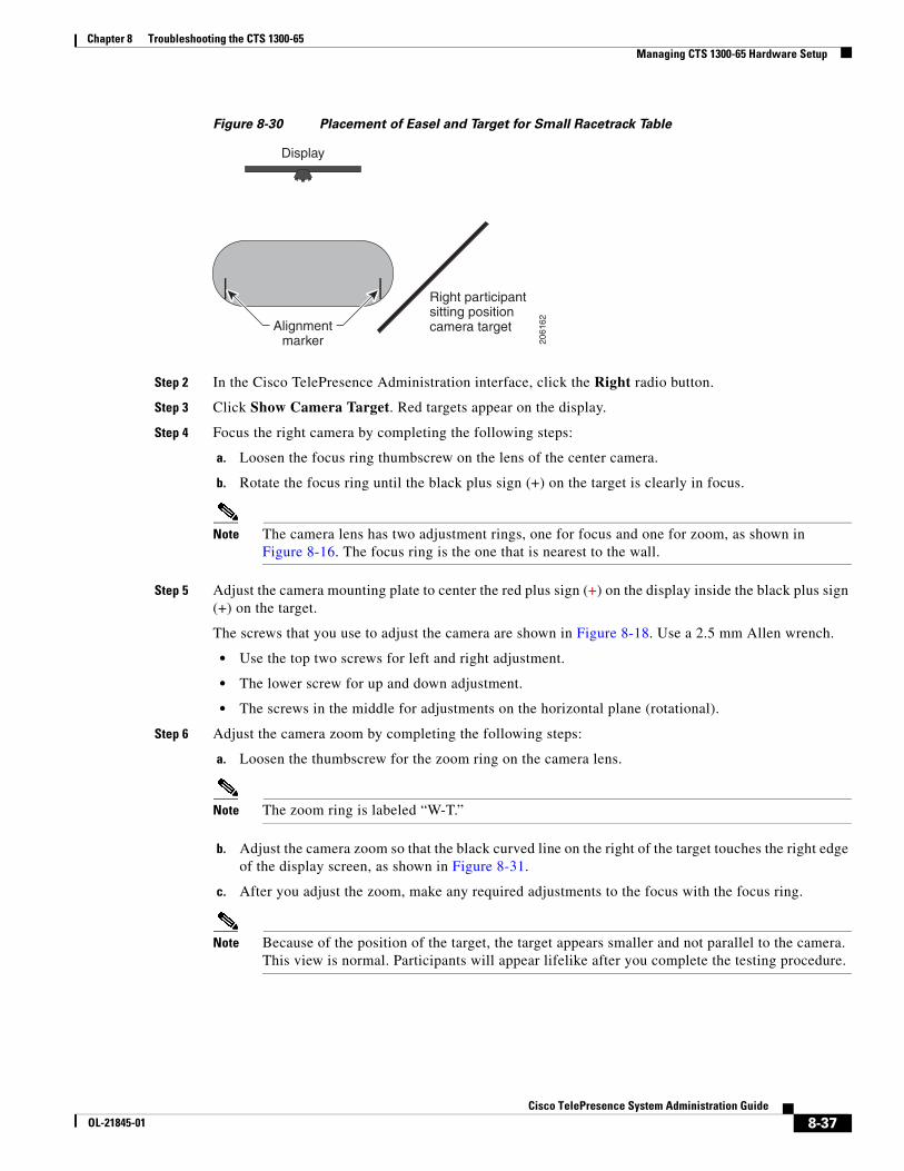
Step 1 Move the large camera target to the far corner of the racetrack table, as shown in Figure 8-30.
8-36Cisco TelePresence System Administration Guide
OL-21845-01
Chapter 8 Troubleshooting the CTS 1300-65 Managing CTS 1300-65 Hardware Setup
Figure 8-30 Placement of Easel and Target for Small Racetrack Table
Step 2 In the Cisco TelePresence Administration interface, click the Right radio button.
Step 3 Click Show Camera Target. Red targets appear on the display.
Step 4 Focus the right camera by completing the following steps:
a. Loosen the focus ring thumbscrew on the lens of the center camera.
b. Rotate the focus ring until the black plus sign (+) on the target is clearly in focus.
Note The camera lens has two adjustment rings, one for focus and one for zoom, as shown in Figure 8-16. The focus ring is the one that is nearest to the wall.
Step 5 Adjust the camera mounting plate to center the red plus sign (+) on the display inside the black plus sign (+) on the target.
The screws that you use to adjust the camera are shown in Figure 8-18. Use a 2.5 mm Allen wrench.
• Use the top two screws for left and right adjustment.
• The lower screw for up and down adjustment.
• The screws in the middle for adjustments on the horizontal plane (rotational).
Step 6 Adjust the camera zoom by completing the following steps:
a. Loosen the thumbscrew for the zoom ring on the camera lens.
Note The zoom ring is labeled “W-T.”
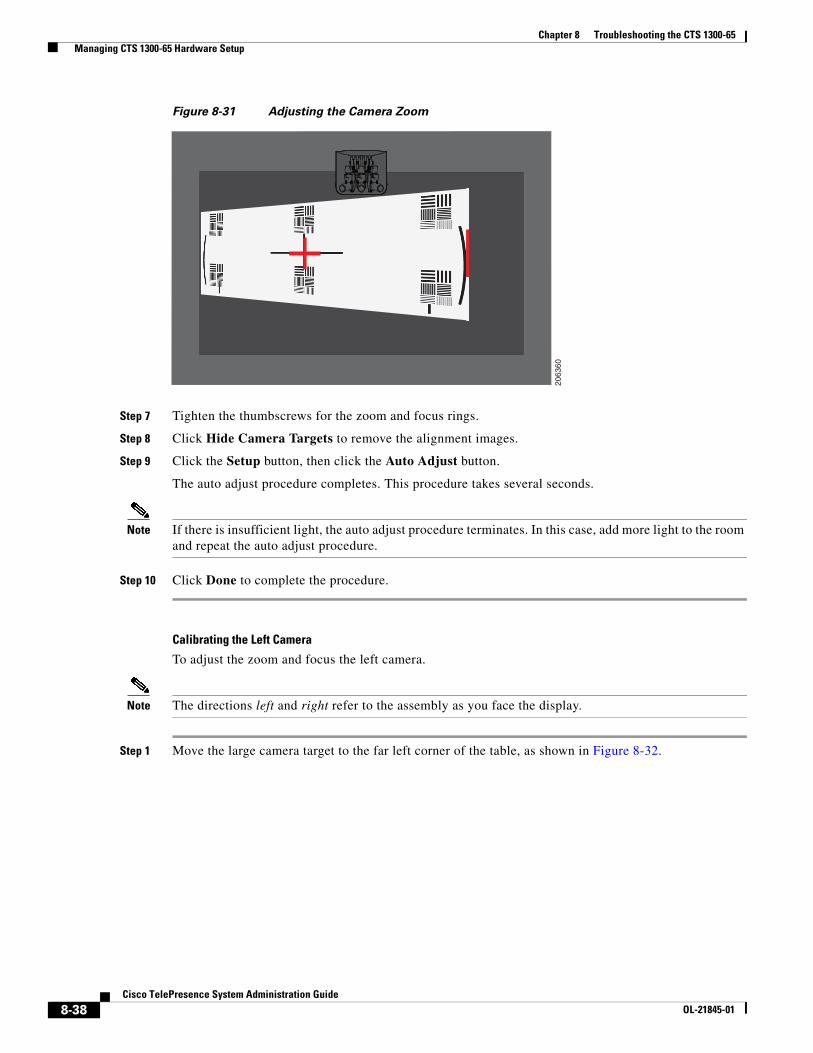
b. Adjust the camera zoom so that the black curved line on the right of the target touches the right edge of the display screen, as shown in Figure 8-31.
c. After you adjust the zoom, make any required adjustments to the focus with the focus ring.
Note Because of the position of the target, the target appears smaller and not parallel to the camera. This view is normal. Participants will appear lifelike after you complete the testing procedure.
Display
2061
62
Right participantsitting positioncamera targetAlignment
marker
8-37Cisco TelePresence System Administration Guide
OL-21845-01
Chapter 8 Troubleshooting the CTS 1300-65 Managing CTS 1300-65 Hardware Setup
Figure 8-31 Adjusting the Camera Zoom
Step 7 Tighten the thumbscrews for the zoom and focus rings.
Step 8 Click Hide Camera Targets to remove the alignment images.
Step 9 Click the Setup button, then click the Auto Adjust button.
The auto adjust procedure completes. This procedure takes several seconds.
Note If there is insufficient light, the auto adjust procedure terminates. In this case, add more light to the room and repeat the auto adjust procedure.
Step 10 Click Done to complete the procedure.
Calibrating the Left Camera
To adjust the zoom and focus the left camera.
Note The directions left and right refer to the assembly as you face the display.
Step 1 Move the large camera target to the far left corner of the table, as shown in Figure 8-32.
2063
60
8-38Cisco TelePresence System Administration Guide
OL-21845-01
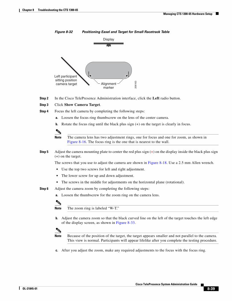
Chapter 8 Troubleshooting the CTS 1300-65 Managing CTS 1300-65 Hardware Setup
Figure 8-32 Positioning Easel and Target for Small Racetrack Table
Step 2 In the Cisco TelePresence Administration interface, click the Left radio button.
Step 3 Click Show Camera Target.
Step 4 Focus the left camera by completing the following steps:
a. Loosen the focus ring thumbscrew on the lens of the center camera.
b. Rotate the focus ring until the black plus sign (+) on the target is clearly in focus.
Note The camera lens has two adjustment rings, one for focus and one for zoom, as shown in Figure 8-16. The focus ring is the one that is nearest to the wall.
Step 5 Adjust the camera mounting plate to center the red plus sign (+) on the display inside the black plus sign (+) on the target.
The screws that you use to adjust the camera are shown in Figure 8-18. Use a 2.5 mm Allen wrench.
• Use the top two screws for left and right adjustment.
• The lower screw for up and down adjustment.
• The screws in the middle for adjustments on the horizontal plane (rotational).
Step 6 Adjust the camera zoom by completing the following steps:
a. Loosen the thumbscrew for the zoom ring on the camera lens.
Note The zoom ring is labeled “W-T.”
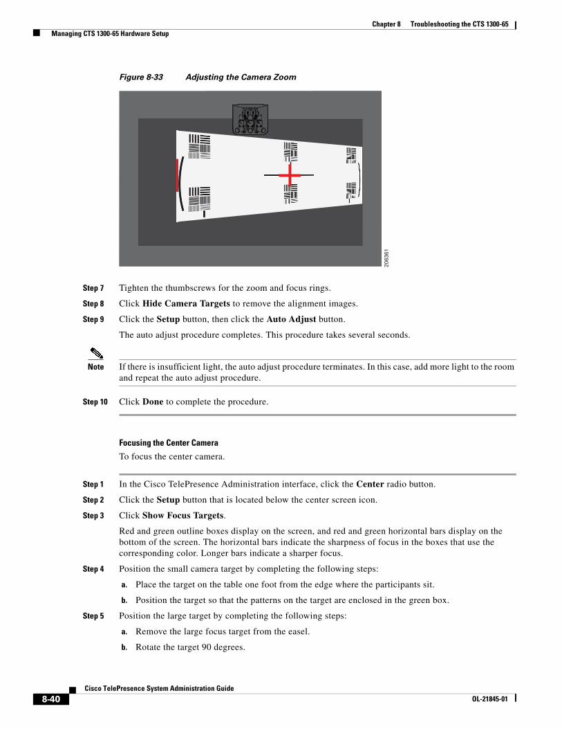
b. Adjust the camera zoom so that the black curved line on the left of the target touches the left edge of the display screen, as shown in Figure 8-33.
Note Because of the position of the target, the target appears smaller and not parallel to the camera. This view is normal. Participants will appear lifelike after you complete the testing procedure.
c. After you adjust the zoom, make any required adjustments to the focus with the focus ring.
Display
2061
63Alignmentmarker
Left participantsitting positioncamera target
8-39Cisco TelePresence System Administration Guide
OL-21845-01
Chapter 8 Troubleshooting the CTS 1300-65 Managing CTS 1300-65 Hardware Setup
Figure 8-33 Adjusting the Camera Zoom
Step 7 Tighten the thumbscrews for the zoom and focus rings.
Step 8 Click Hide Camera Targets to remove the alignment images.
Step 9 Click the Setup button, then click the Auto Adjust button.
The auto adjust procedure completes. This procedure takes several seconds.
Note If there is insufficient light, the auto adjust procedure terminates. In this case, add more light to the room and repeat the auto adjust procedure.
Step 10 Click Done to complete the procedure.
Focusing the Center Camera
To focus the center camera.
Step 1 In the Cisco TelePresence Administration interface, click the Center radio button.
Step 2 Click the Setup button that is located below the center screen icon.
Step 3 Click Show Focus Targets.
Red and green outline boxes display on the screen, and red and green horizontal bars display on the bottom of the screen. The horizontal bars indicate the sharpness of focus in the boxes that use the corresponding color. Longer bars indicate a sharper focus.
Step 4 Position the small camera target by completing the following steps:
a. Place the target on the table one foot from the edge where the participants sit.
b. Position the target so that the patterns on the target are enclosed in the green box.
Step 5 Position the large target by completing the following steps:
a. Remove the large focus target from the easel.
b. Rotate the target 90 degrees.
2063
61
8-40Cisco TelePresence System Administration Guide
OL-21845-01
Chapter 8 Troubleshooting the CTS 1300-65 Managing CTS 1300-65 Hardware Setup
c. Have another person hold the target upright.
Note If another person is not available, clamp the top of the target into the clamp at the top of the easel.
d. Place the top of the easel five feet behind the top of the small target.
e. Position the target so that the topmost patterns are enclosed in the red box.
Step 6 Adjust the focus on the left camera by completing the following steps:
a. Loosen the thumbscrew for the lens focus ring.
b. Twist the focus ring clockwise until the red and green horizontal bars on the bottom of the screen are reduced to very short lengths on the left.
Note Figure 8-34 shows a mirror image of the horizontal bars.
c. Twist the focus ring counter-clockwise until the red and green bars extend all the way to the right.
d. Continue to twist the focus ring until the red and green bars are approximately the same length. See Figure 8-34 to view the approximate horizontal bar alignment. When the bars are roughly the same length, the camera is focused.
Note The red and green bars do not have to be exactly the same length, but get them as close as you can.
Figure 8-34 Horizontal Bars and Focusing Targets
e. Without moving the focus ring, tighten its thumbscrew.
Step 7 Click Done to complete the right camera focusing procedure.
Focusing the Right Camera
To focus the right camera.
2063
62
Redrectangle
Greenrectangle
Largetarget
Smalltarget
Red and greenhorizontal bars
8-41Cisco TelePresence System Administration Guide
OL-21845-01
Chapter 8 Troubleshooting the CTS 1300-65 Managing CTS 1300-65 Hardware Setup
Step 1 In the Cisco TelePresence Administration interface, click the Right radio button.
Step 2 Click the Setup button that is located below the center screen icon.
Step 3 Click Show Focus Targets.
Step 4 Position the small camera target by completing the following steps:
a. Place the target on the table one foot from the edge where the participants sit.
b. Position the target so that the topmost patterns on the target are enclosed in the green box.
Step 5 Position the large target by completing the following steps:
a. Remove the large focus target from the easel.
b. Rotate the target 90 degrees.
c. Have another person hold the target upright.
Note If another person is not available, clamp the top of the target into the clamp at the top of the easel.
d. Place the top of the easel five feet behind the top of the small target.
e. Position the target so that the topmost patterns are enclosed in the red box.
Step 6 Adjust the camera focus by completing the following steps:
a. Loosen the thumbscrew for the lens focus ring.
b. Twist the focus ring clockwise until the red and green horizontal bars on the bottom of the screen are reduced to very short lengths on the left.
Note Figure 8-34 shows a mirror image of the horizontal bars.
c. Twist the focus ring counter-clockwise until the red and green bars extend all the way to the right.
d. Continue to twist the focus ring until the red and green bars are approximately the same length. See Figure 8-34 to view the approximate horizontal bar alignment. When the bars are roughly the same length, the camera is focused.
Note The red and green bars do not have to be exactly the same length, but get them as close as you can.
e. Without moving the focus ring, tighten its thumbscrew.
Step 7 Click Done to complete the right camera focusing procedure.
Focusing the Left Camera
To focus the left camera.
Step 1 In the Cisco TelePresence Administration interface, click the Left radio button.
Step 2 Click the Setup button that is located below the center screen icon.
Step 3 Click Show Focus Targets.
8-42Cisco TelePresence System Administration Guide
OL-21845-01
Chapter 8 Troubleshooting the CTS 1300-65 Managing CTS 1300-65 Hardware Setup
Step 4 Position the small camera target by completing the following steps:
a. Place the target on the table one foot from the edge where the participants sit.
b. Position the target so that the topmost patterns on the target are enclosed in the green box.
Step 5 Position the large target by completing the following steps:
a. Remove the large focus target from the easel.
b. Rotate the target 90 degrees.
c. Have another person hold the target upright.
Note If another person is not available, clamp the top of the target into the clamp at the top of the easel.
d. Place the top of the easel five feet behind the top of the small target.
e. Position the target so that the topmost patterns are enclosed in the red box.
Step 6 Adjust the focus on the left camera by completing the following steps:
a. Loosen the thumbscrew for the lens focus ring.
b. Twist the focus ring clockwise until the red and green horizontal bars on the bottom of the screen are reduced to very short lengths on the left.
Note Figure 8-34 shows a mirror image of the horizontal bars.
c. Twist the focus ring counter-clockwise until the red and green bars extend all the way to the right.
d. Continue to twist the focus ring until the red and green bars are approximately the same length. See Figure 8-34 to view the approximate horizontal bar alignment. When the bars are roughly the same length, the camera is focused.
Note The red and green bars do not have to be exactly the same length, but get them as close as you can.
e. Without moving the focus ring, tighten its thumbscrew.
Step 7 Click Done to complete the right camera focusing procedure.
Saving Your Settings
When you have configured all your settings:
Step 1 Click Apply to register new or modified settings.
Step 2 Click Reset to restore the original settings.
For more information about testing and troubleshooting the CTS 1300-65, see the Setting Up the Camera section in the First-Time Setup chapter of the Cisco TelePresence 1300-65 Assembly, Use & Care, and Field-Replacement Unit Guide.
8-43Cisco TelePresence System Administration Guide
OL-21845-01
Chapter 8 Troubleshooting the CTS 1300-65 Managing CTS 1300-65 Hardware Setup
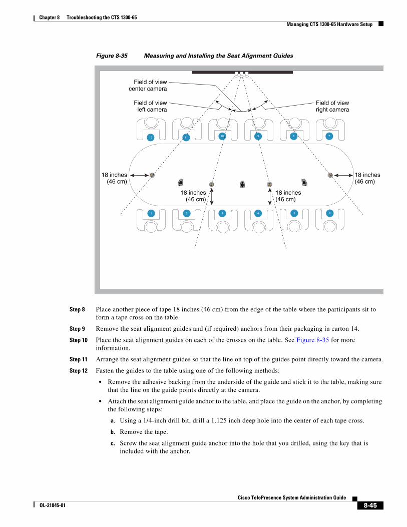
Arranging the Seat Alignment Guides
Conference participants should be seated in an area that is completely within the field of view of one of the three cameras. To ensure this requirement, Cisco provides you with Seat Alignment Guides. After you set up the cameras, you place these guides on the table; these guides show the field of view for each camera.
To place the seat alignment guides on the table:
Step 1 Using a supported Internet browser, log in to the Cisco TelePresence System administration interface.
Step 2 Select the correct table type by completing the following steps:
Step 3 Navigate to Troubleshooting > Hardware Setup
Step 4 Click the Cameras radio button.
Step 5 Click Start to display the image of the cameras in the displays.
Step 6 Note the field of view for each camera.
Step 7 Using non-marking tape (for example, masking tape), tape a mark on the table that denotes the edge of the field of view for each camera.
Place this mark approximately 18 inches (46 cm) from the edge of the table, and point the line of tape at the camera.
Tip If you cannot determine the camera range, use this guide for marking the table: The focal range of the center segment is approximately 5 feet (152 cm) wide from where the participants sit. The focal range of each side segment is approximately 4 feet six inches (137 cm) wide.
Mark the table in four places:
• Edge of camera view, left camera
• Edge of view between left and center camera
• Edge of view between center and right camera
• Edge of camera view, right camera
Note If your table is narrow, omit the two markings on the outer edges.
8-44Cisco TelePresence System Administration Guide
OL-21845-01
Chapter 8 Troubleshooting the CTS 1300-65 Managing CTS 1300-65 Hardware Setup
Figure 8-35 Measuring and Installing the Seat Alignment Guides
Step 8 Place another piece of tape 18 inches (46 cm) from the edge of the table where the participants sit to form a tape cross on the table.
Step 9 Remove the seat alignment guides and (if required) anchors from their packaging in carton 14.
Step 10 Place the seat alignment guides on each of the crosses on the table. See Figure 8-35 for more information.
Step 11 Arrange the seat alignment guides so that the line on top of the guides point directly toward the camera.
Step 12 Fasten the guides to the table using one of the following methods:
• Remove the adhesive backing from the underside of the guide and stick it to the table, making sure that the line on the guide points directly at the camera.
• Attach the seat alignment guide anchor to the table, and place the guide on the anchor, by completing the following steps:
a. Using a 1/4-inch drill bit, drill a 1.125 inch deep hole into the center of each tape cross.
b. Remove the tape.
c. Screw the seat alignment guide anchor into the hole that you drilled, using the key that is included with the anchor.
2 3 4 5
11 10 9 8
1
12
6
7
Field of viewcenter camera
Field of viewleft camera
18 inches(46 cm)
Field of viewright camera
18 inches(46 cm)
18 inches(46 cm)
18 inches(46 cm)
8-45Cisco TelePresence System Administration Guide
OL-21845-01
Chapter 8 Troubleshooting the CTS 1300-65 Managing CTS 1300-65 Hardware Setup
d. Place the seat alignment guide on top of the anchor.
e. Rotate the anchor until the line on top of the seat alignment guide points directly at the camera.
Understanding Camera Setup Choices for Room Lighting
If your room has windows that contribute a significant amount of natural light, you can set your CTS to automatically compensate for variable lighting conditions. This compensation is an average adjustment and will not be as accurate as the color settings you select for a room that uses fixed, artificial room lighting.
Table 8-2 contains recommendations for desirable display and camera settings when you set up the display and camera. See the “Testing the CTS 1300-65 Cameras” section on page 8-7 for more information.
Troubleshooting Cameras
Use the information in Table 8-3 to troubleshoot problems with cameras.
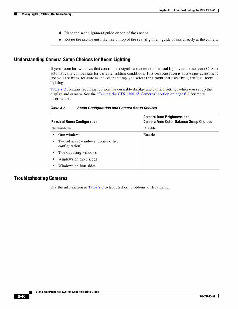
Table 8-2 Room Configuration and Camera Setup Choices
Physical Room ConfigurationCamera Auto Brightness and Camera Auto Color Balance Setup Choices
No windows Disable
• One window
• Two adjacent windows (corner office configuration)
• Two opposing windows
• Windows on three sides
• Windows on four sides
Enable
8-46Cisco TelePresence System Administration Guide
OL-21845-01
Chapter 8 Troubleshooting the CTS 1300-65 Managing CTS 1300-65 Hardware Setup
Related Information
For more information about setting up and testing cameras, see the Cisco TelePresence System 1300-65 Assembly, Use & Care, and Field Replacement Unit Guide.
For more system troubleshooting information, see the Cisco TelePresence System Troubleshooting Guide on Cisco.com.
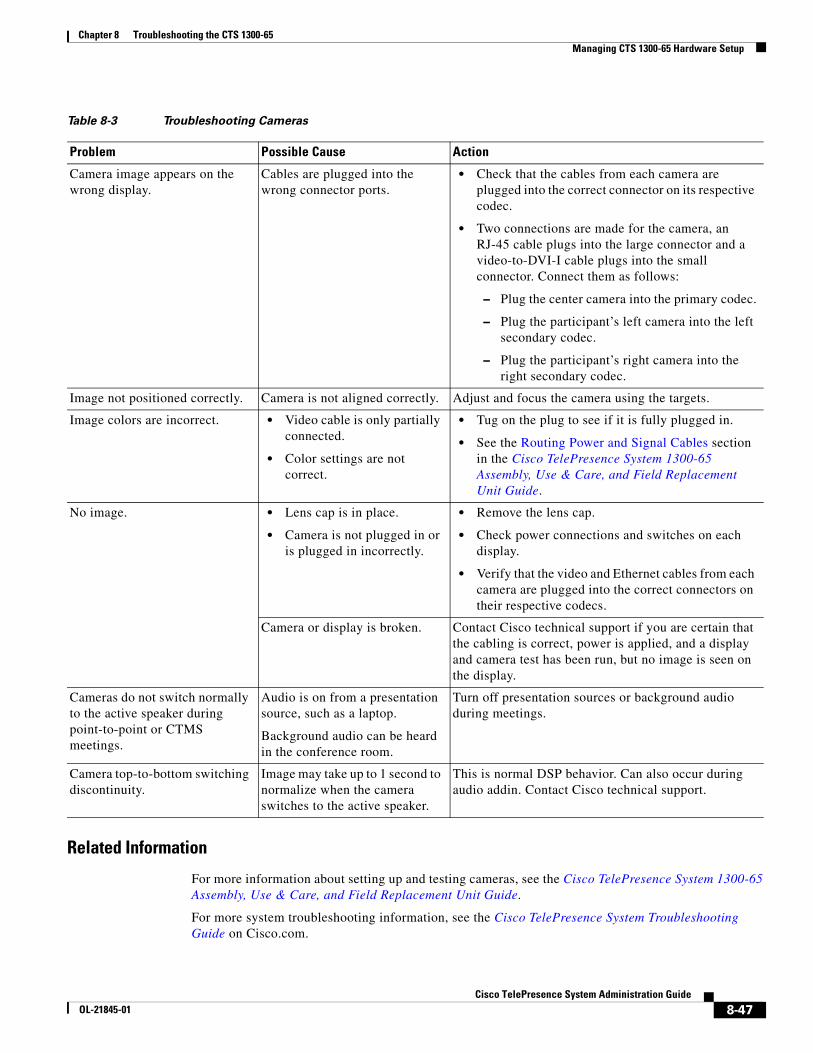
Table 8-3 Troubleshooting Cameras
Problem Possible Cause Action
Camera image appears on the wrong display.
Cables are plugged into the wrong connector ports.
• Check that the cables from each camera are plugged into the correct connector on its respective codec.
• Two connections are made for the camera, an RJ-45 cable plugs into the large connector and a video-to-DVI-I cable plugs into the small connector. Connect them as follows:
– Plug the center camera into the primary codec.
– Plug the participant’s left camera into the left secondary codec.
– Plug the participant’s right camera into the right secondary codec.
Image not positioned correctly. Camera is not aligned correctly. Adjust and focus the camera using the targets.
Image colors are incorrect. • Video cable is only partially connected.
• Color settings are not correct.
• Tug on the plug to see if it is fully plugged in.
• See the Routing Power and Signal Cables section in the Cisco TelePresence System 1300-65 Assembly, Use & Care, and Field Replacement Unit Guide.
No image. • Lens cap is in place.
• Camera is not plugged in or is plugged in incorrectly.
• Remove the lens cap.
• Check power connections and switches on each display.
• Verify that the video and Ethernet cables from each camera are plugged into the correct connectors on their respective codecs.
Camera or display is broken. Contact Cisco technical support if you are certain that the cabling is correct, power is applied, and a display and camera test has been run, but no image is seen on the display.
Cameras do not switch normally to the active speaker during point-to-point or CTMS meetings.
Audio is on from a presentation source, such as a laptop.
Background audio can be heard in the conference room.
Turn off presentation sources or background audio during meetings.
Camera top-to-bottom switching discontinuity.
Image may take up to 1 second to normalize when the camera switches to the active speaker.
This is normal DSP behavior. Can also occur during audio addin. Contact Cisco technical support.
8-47Cisco TelePresence System Administration Guide
OL-21845-01
Chapter 8 Troubleshooting the CTS 1300-65 Managing CTS 1300-65 Hardware Setup
Testing SpeakersThe speakers are set up successfully when sound can be heard clearly from each one. When running a test, you can choose whether to cycle through the speakers automatically or manually.
Use the information in the following sections to test the speakers for your system:
• Testing the Speakers, page 8-48
• Troubleshooting Speakers, page 8-48
• Related Information, page 8-49
Testing the Speakers
To test the speakers:
Step 1 Log in to the Cisco TelePresence System Administration interface.
Step 2 Choose Troubleshooting > Hardware Setup
Step 3 Click the Speakers radio button.
Step 4 Click Start to begin the speaker test.
Step 5 Click Cycle Through Speakers to have sound cycled automatically for 5 seconds on each speaker.
Step 6 Click Manually Step Through Speakers to test sound on each speaker.
Step 7 Click Next Speaker to progress to the next speaker.
Step 8 Click Stop to end testing.
Troubleshooting Speakers
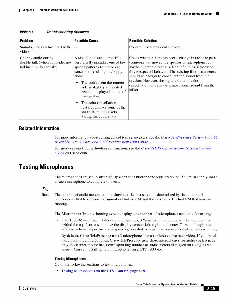
Use the information in Table 8-4 to troubleshoot problems with speakers.
Table 8-4 Troubleshooting Speakers
Problem Possible Cause Possible Solution
No sound is heard. Speaker cable is not connected or is only partially connected.
• Check that the red and black pronged ends of the speaker cable are securely fastened under their corresponding connectors on the speaker.
• Check that the speaker cable is plugged into the correct receptor on the primary codec.
• Tug on the plug to see if it is fully plugged in. Push the plug in firmly until a click is heard.
Sound heard at wrong speaker. Speaker cable is not connected in the correct connector.
Check that the speaker cable is plugged into the correct receptor on the primary codec. Plug all speakers into the primary codec.
8-48Cisco TelePresence System Administration Guide
OL-21845-01
Chapter 8 Troubleshooting the CTS 1300-65 Managing CTS 1300-65 Hardware Setup
Related Information
For more information about setting up and testing speakers, see the Cisco TelePresence System 1300-65 Assembly, Use & Care, and Field Replacement Unit Guide.
For more system troubleshooting information, see the Cisco TelePresence System Troubleshooting Guide on Cisco.com.
Testing MicrophonesThe microphones are set up successfully when each microphone registers sound. You must supply sound at each microphone to complete this test.
Note The number of audio meters that are shown on the test screen is determined by the number of microphones that have been configured in Unified CM and the version of Unified CM that you are running.
The Microphone Troubleshooting screen displays the number of microphones available for testing:
• CTS 1300-65—3 “fixed” table-top microphones, 3 “positional” microphones that are mounted behind the top front cover above the display screen: left, right, and center. These microphones establish where the person who is speaking is seated to determine voice-activated camera switching.
By default, Cisco TelePresence uses 3 microphones for a conference that uses video. If you install more than three microphones, Cisco TelePresence uses those microphones for audio conferences only. Each microphone has a corresponding number of audio meters displayed on a single test screen. You can install up to 6 microphones on a CTS 1300-65.
Testing Microphones
Go to the following sections to test microphones:
• Testing Microphones on the CTS 1300-65, page 8-50
Sound is not synchronized with video.
— Contact Cisco technical support.
Choppy audio during double-talk (when both sides are talking simultaneously).
Audio Echo Canceller (AEC) very briefly mistakes one of the speech patterns for noise and cancels it, resulting in choppy audio.
• The audio from the remote side is slightly attenuated before it is played out the of the speaker.
• The echo cancellation feature removes some of the sound from the talkers during the double talk.
Check whether there has been a change in the echo path (someone has moved the speaker or microphone, or maybe a laptop directly in front of a mic). Otherwise, this is expected behavior. The existing filter parameters should be enough to cancel out the sound from the speaker. However, during double-talk, echo cancellation will always remove some sound from the talker.
Table 8-4 Troubleshooting Speakers
Problem Possible Cause Possible Solution
8-49Cisco TelePresence System Administration Guide
OL-21845-01
Chapter 8 Troubleshooting the CTS 1300-65 Managing CTS 1300-65 Hardware Setup
• Configuring Additional Microphones for Audio-Only Conferences, page 8-52
• Troubleshooting Microphones, page 8-52
• Related Information, page 8-54
Testing Microphones on the CTS 1300-65
To test microphones on the CTS 1300-65:
Step 1 Place the microphones around your table. See the Cisco TelePresence System 1300-65 Room Recommendations chapter in the Cisco TelePresence System 1300-65 Assembly, First-Time Setup, and Field-Replaceable Unit Guide for the correct microphone placement.
Step 2 Log in to the Cisco TelePresence System Administration interface.
Step 3 Choose Troubleshooting > Hardware Setup.
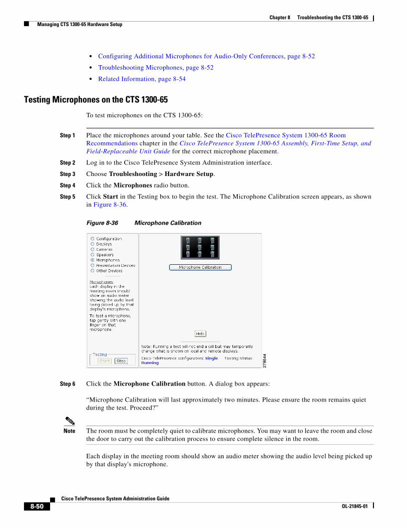
Step 4 Click the Microphones radio button.
Step 5 Click Start in the Testing box to begin the test. The Microphone Calibration screen appears, as shown in Figure 8-36.
Figure 8-36 Microphone Calibration
Step 6 Click the Microphone Calibration button. A dialog box appears:
“Microphone Calibration will last approximately two minutes. Please ensure the room remains quiet during the test. Proceed?”
Note The room must be completely quiet to calibrate microphones. You may want to leave the room and close the door to carry out the calibration process to ensure complete silence in the room.
Each display in the meeting room should show an audio meter showing the audio level being picked up by that display's microphone.
8-50Cisco TelePresence System Administration Guide
OL-21845-01
Chapter 8 Troubleshooting the CTS 1300-65 Managing CTS 1300-65 Hardware Setup
• The center display should show three microphones. A microphone that is not connected has a red slash.
• The left and right displays should show three microphones unless the room is configured for seven microphones. If microphones at the far left or right are connected, they appear on the display with a yellow question mark.
Step 7 Click Ok to proceed with the calibration.
Step 8 Test each microphone by tapping gently with one finger.
Step 9 Click Stop to end the test.
8-51Cisco TelePresence System Administration Guide
OL-21845-01
Chapter 8 Troubleshooting the CTS 1300-65 Managing CTS 1300-65 Hardware Setup
Configuring Additional Microphones for Audio-Only Conferences
Cisco TelePresence uses three microphones for a conference that uses video. You can configure up to three additional microphones to use during audio-only conferences. Cisco TelePresence uses these additional microphones for audio conferences only.
To configure additional microphones for audio-only conferences, complete the following tasks:
Step 1 Connect the microphones normally to the audio/video extension unit.
You can connect one to three additional microphones (four to six microphones total).
Step 2 Log in to the Cisco Unified Communications Manager Administration GUI
Step 3 Navigate to Device > Phones.
Step 4 Find the CTS 1300-65 device that you want to configure and click the hyperlink next to the device to select it.
Step 5 In the Product Specific Configuration Layout area, enter either 4 table microphones, 5 table microphones, or 6 table microphones in the Total Microphone Count drop-down list.
Step 6 Click Save to save your changes.
Troubleshooting Microphones
Use the information in Table 8-5 to troubleshoot problems with microphones.
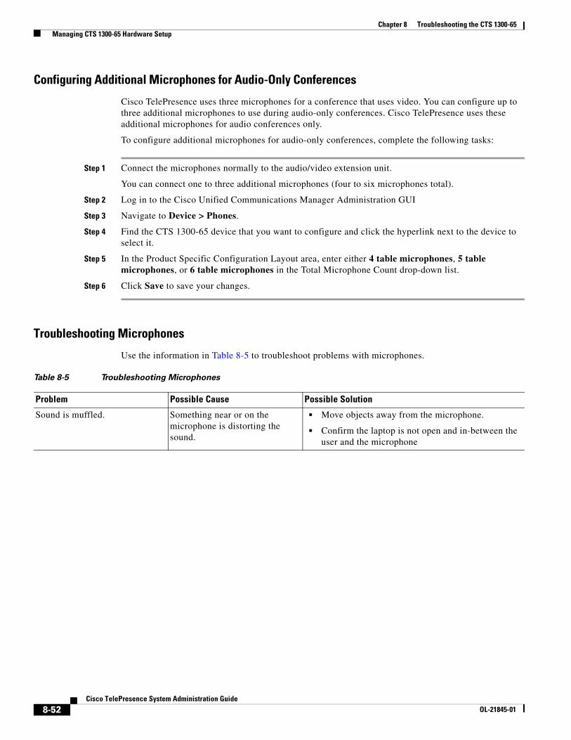
Table 8-5 Troubleshooting Microphones
Problem Possible Cause Possible Solution
Sound is muffled. Something near or on the microphone is distorting the sound.
• Move objects away from the microphone.
• Confirm the laptop is not open and in-between the user and the microphone
8-52Cisco TelePresence System Administration Guide
OL-21845-01

Chapter 8 Troubleshooting the CTS 1300-65 Managing CTS 1300-65 Hardware Setup
No sound registers. Microphone cable is not connected or is only partially connected.
• Check that the system is plugged in and power is on.
• Check that the microphone plug is firmly seated in the correct connector on the primary codec.
• Check that the mute light on each microphone is lit. An unlit light indicates that the microphone is not plugged in.
• Lightly tap the microphone to see if sound registers.
• Contact Cisco technical support if you are certain that the cabling is correct and power is applied to the system, but no sound registers on the microphone.
Microphone icon with red pipe displays.
Microphone is not connected.
One of the microphones is unplugged.
Check that the microphone is properly plugged in.
Sound registers at the wrong microphone.
Microphone cable is not connected to its corresponding codec.
• Check that the cable from the microphone is plugged into the correct receptor on the codec.
• Plug all microphones into the primary codec.
Microphone switches to a segment that has no one talking.
Phantom switching. Run the microphone calibration procedure in the “Testing Microphones on the CTS 1300-65” section on page 8-50.
Choppy audio during double-talk (when both sides are talking simultaneously).
Audio Echo Canceller (AEC) very briefly mistakes one of the speech patterns for noise and cancels it, resulting in choppy audio.
• The audio from the remote side is slightly attenuated before it is played out the of the speaker.
• The echo cancellation feature removes some of the sound from the talkers during the double talk.
Check whether there has been a change in the echo path (someone has moved the speaker or microphone, or maybe a laptop directly in front of a mic). Otherwise, this is expected behavior. The existing filter parameters should be enough to cancel out the sound from the speaker. However, during double-talk, echo cancellation will always remove some sound from the talker.
Table 8-5 Troubleshooting Microphones (continued)
Problem Possible Cause Possible Solution
8-53Cisco TelePresence System Administration Guide
OL-21845-01
Chapter 8 Troubleshooting the CTS 1300-65 Managing CTS 1300-65 Hardware Setup
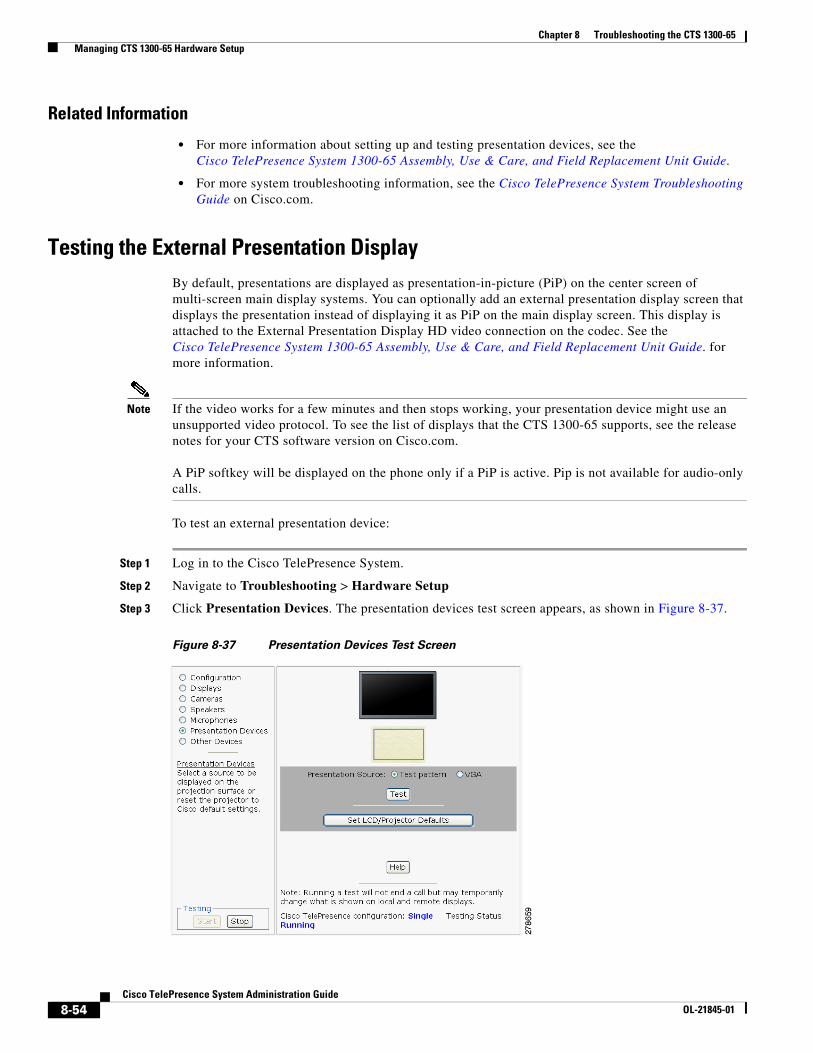
Related Information
• For more information about setting up and testing presentation devices, see the Cisco TelePresence System 1300-65 Assembly, Use & Care, and Field Replacement Unit Guide.
• For more system troubleshooting information, see the Cisco TelePresence System Troubleshooting Guide on Cisco.com.
Testing the External Presentation DisplayBy default, presentations are displayed as presentation-in-picture (PiP) on the center screen of multi-screen main display systems. You can optionally add an external presentation display screen that displays the presentation instead of displaying it as PiP on the main display screen. This display is attached to the External Presentation Display HD video connection on the codec. See the Cisco TelePresence System 1300-65 Assembly, Use & Care, and Field Replacement Unit Guide. for more information.
Note If the video works for a few minutes and then stops working, your presentation device might use an unsupported video protocol. To see the list of displays that the CTS 1300-65 supports, see the release notes for your CTS software version on Cisco.com.
A PiP softkey will be displayed on the phone only if a PiP is active. Pip is not available for audio-only calls.
To test an external presentation device:
Step 1 Log in to the Cisco TelePresence System.
Step 2 Navigate to Troubleshooting > Hardware Setup
Step 3 Click Presentation Devices. The presentation devices test screen appears, as shown in Figure 8-37.
Figure 8-37 Presentation Devices Test Screen
8-54Cisco TelePresence System Administration Guide
OL-21845-01
Chapter 8 Troubleshooting the CTS 1300-65 Managing CTS 1300-65 Hardware Setup
Step 4 Proceed to Testing Presentation Devices.
Testing Presentation DevicesThe output for presentations is handled by projectors or auxiliary LCD displays. Input to the projector can be delivered through a Video Graphics Array (VGA) input device (such as a laptop computer).
Note You should run this test only if you have presentation display devices installed.
Table 8-6 contains supported presentation devices listed by system.
The projector is set up successfully when the test pattern is displayed on the projection surface in the meeting room while running the test.
Tip When troubleshooting presentation devices, start with the projector test pattern to see if the projector is set up correctly and then proceed through VGA and document camera input tests as necessary.
Use the information in the following sections to test presentation devices:
• Checking the Test Pattern, page 8-55
• Checking the VGA, page 8-56
• Resetting the Projector, page 8-57
• Troubleshooting Presentation Devices, page 8-57
• Related Information, page 8-54
Checking the Test Pattern
To check the test pattern:
Step 1 Log in to the Cisco TelePresence System Administration interface.
Step 2 Choose Troubleshooting > Hardware Setup.
Step 3 Click the Presentation Devices radio button.
Step 4 Click Start in the Testing box. The Presentation Source buttons are activated.
Step 5 Select Test Pattern and click Test. The test pattern screen appears, as shown in
Table 8-6 Supported Presentation Devices
Presentation Device
Included in Cisco TelePresence System
• CTS 1300-65
Optional in Cisco TelePresence System
—Projector
8-55Cisco TelePresence System Administration Guide
OL-21845-01
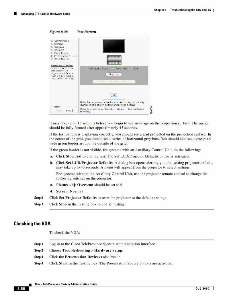
Chapter 8 Troubleshooting the CTS 1300-65 Managing CTS 1300-65 Hardware Setup
Figure 8-38 Test Pattern
It may take up to 15 seconds before you begin to see an image on the projection surface. The image should be fully formed after approximately 45 seconds.
If the test pattern is displaying correctly, you should see a grid projected on the projection surface. In the center of the grid, you should see a series of horizontal grey bars. You should also see a one-pixel wide green border around the outside of the grid.
If the green border is not visible, for systems with an Auxiliary Control Unit, do the following:
a. Click Stop Test to end the test. The Set LCD/Projector Defaults button is activated.
b. Click Set LCD/Projector Defaults. A dialog box opens alerting you that setting projector defaults may take up to 45 seconds. A menu will appear from the projector to select settings.
For systems without the Auxiliary Control Unit, use the projector remote control to change the following settings on the projector:
c. Picture adj: Overscan should be set to 0
d. Screen: Normal
Step 6 Click Set Projector Defaults to reset the projector to the default settings.
Step 7 Click Stop in the Testing box to end all testing.
Checking the VGA
To check the VGA:
Step 1 Log in to the Cisco TelePresence System Administration interface.
Step 2 Choose Troubleshooting > Hardware Setup.
Step 3 Click the Presentation Devices radio button.
Step 4 Click Start in the Testing box. The Presentation Source buttons are activated.
8-56Cisco TelePresence System Administration Guide
OL-21845-01
Chapter 8 Troubleshooting the CTS 1300-65 Managing CTS 1300-65 Hardware Setup
Step 5 Select VGA and click Test. It may take up to 15 seconds before you begin to see an image on the projection surface. The image should be fully formed after approximately 45 seconds.
If the input image is displaying correctly, you should see an image projected on the projection surface. If the image is out of focus, use the projector focus ring to focus the image.
Step 6 Click Stop Test to end the test.
Step 7 Click Set LCD/Projector Defaults to reset the projector to the default settings, if necessary.
Step 8 Click Stop in the Testing box to end all testing.
Resetting the Projector
To reset the projector:
Step 1 Log in to the Cisco TelePresence System Administration interface.
Step 2 Choose Troubleshooting > Hardware Setup.
Step 3 Click the Presentation Devices radio button.
Step 4 Click Start in the Testing box. The Presentation Source buttons are activated.
Step 5 Click Set Projector Defaults to reset the projector to the default settings.
Step 6 Click Stop in the Testing box to complete the task.
Troubleshooting Presentation Devices
Use the information in the following sections to troubleshoot presentation devices:
• Multiple Input Devices, page 8-57
• Presentation Devices, page 8-57
Multiple Input Devices
The Cisco TelePresence System can display information from multiple input devices during a meeting. If multiple input devices are sending information, the projector displays the input from the last presentation device sending information. If an input device image is not being seen on the projector screen, try the following:
• VGA devices—Unplug the device from the VGA cable, wait 5 seconds, and then plug the device back in
Presentation Devices
Use the information in Table 8-7 to troubleshoot presentation devices.
8-57Cisco TelePresence System Administration Guide
OL-21845-01
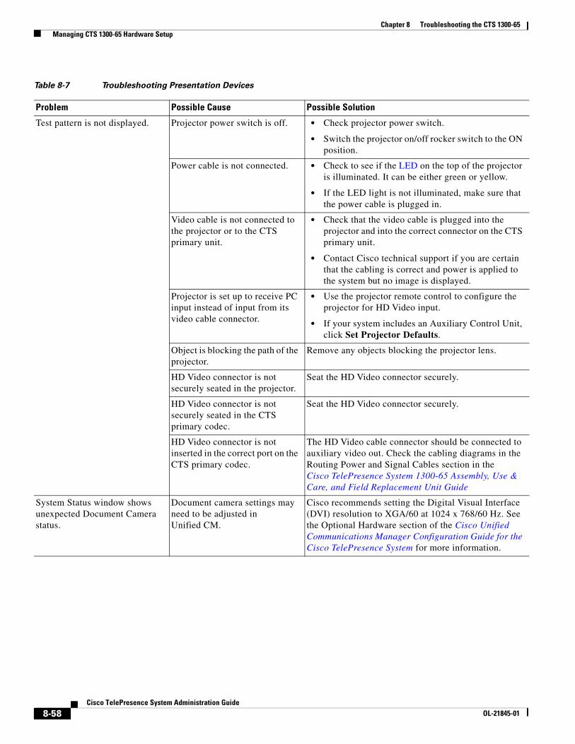
Chapter 8 Troubleshooting the CTS 1300-65 Managing CTS 1300-65 Hardware Setup
Table 8-7 Troubleshooting Presentation Devices
Problem Possible Cause Possible Solution
Test pattern is not displayed. Projector power switch is off. • Check projector power switch.
• Switch the projector on/off rocker switch to the ON position.
Power cable is not connected. • Check to see if the LED on the top of the projector is illuminated. It can be either green or yellow.
• If the LED light is not illuminated, make sure that the power cable is plugged in.
Video cable is not connected to the projector or to the CTS primary unit.
• Check that the video cable is plugged into the projector and into the correct connector on the CTS primary unit.
• Contact Cisco technical support if you are certain that the cabling is correct and power is applied to the system but no image is displayed.
Projector is set up to receive PC input instead of input from its video cable connector.
• Use the projector remote control to configure the projector for HD Video input.
• If your system includes an Auxiliary Control Unit, click Set Projector Defaults.
Object is blocking the path of the projector.
Remove any objects blocking the projector lens.
HD Video connector is not securely seated in the projector.
Seat the HD Video connector securely.
HD Video connector is not securely seated in the CTS primary codec.
Seat the HD Video connector securely.
HD Video connector is not inserted in the correct port on the CTS primary codec.
The HD Video cable connector should be connected to auxiliary video out. Check the cabling diagrams in the Routing Power and Signal Cables section in the Cisco TelePresence System 1300-65 Assembly, Use & Care, and Field Replacement Unit Guide
System Status window shows unexpected Document Camera status.
Document camera settings may need to be adjusted in Unified CM.
Cisco recommends setting the Digital Visual Interface (DVI) resolution to XGA/60 at 1024 x 768/60 Hz. See the Optional Hardware section of the Cisco Unified Communications Manager Configuration Guide for the Cisco TelePresence System for more information.
8-58Cisco TelePresence System Administration Guide
OL-21845-01
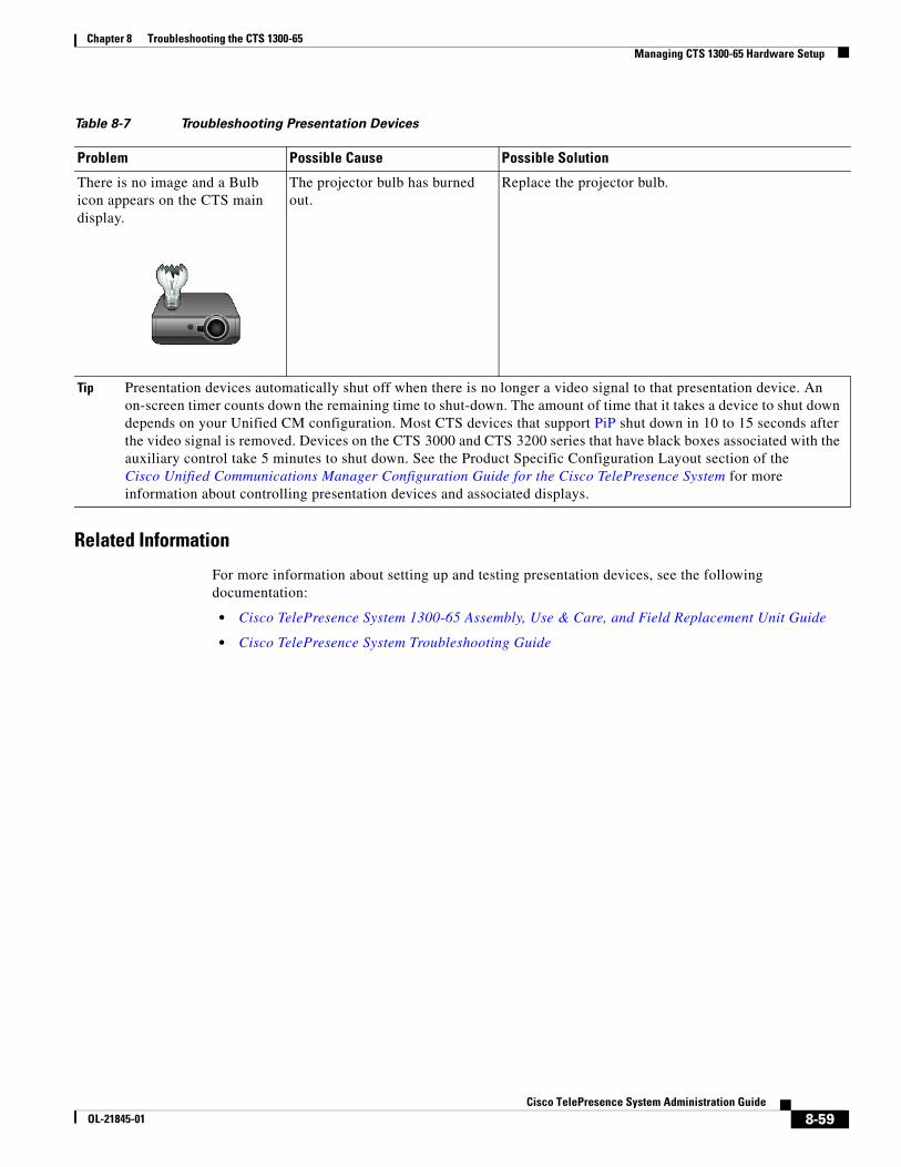
Chapter 8 Troubleshooting the CTS 1300-65 Managing CTS 1300-65 Hardware Setup
Related Information
For more information about setting up and testing presentation devices, see the following documentation:
• Cisco TelePresence System 1300-65 Assembly, Use & Care, and Field Replacement Unit Guide
• Cisco TelePresence System Troubleshooting Guide
There is no image and a Bulb icon appears on the CTS main display.
The projector bulb has burned out.
Replace the projector bulb.
Tip Presentation devices automatically shut off when there is no longer a video signal to that presentation device. An on-screen timer counts down the remaining time to shut-down. The amount of time that it takes a device to shut down depends on your Unified CM configuration. Most CTS devices that support PiP shut down in 10 to 15 seconds after the video signal is removed. Devices on the CTS 3000 and CTS 3200 series that have black boxes associated with the auxiliary control take 5 minutes to shut down. See the Product Specific Configuration Layout section of the Cisco Unified Communications Manager Configuration Guide for the Cisco TelePresence System for more information about controlling presentation devices and associated displays.
Table 8-7 Troubleshooting Presentation Devices
Problem Possible Cause Possible Solution
8-59Cisco TelePresence System Administration Guide
OL-21845-01
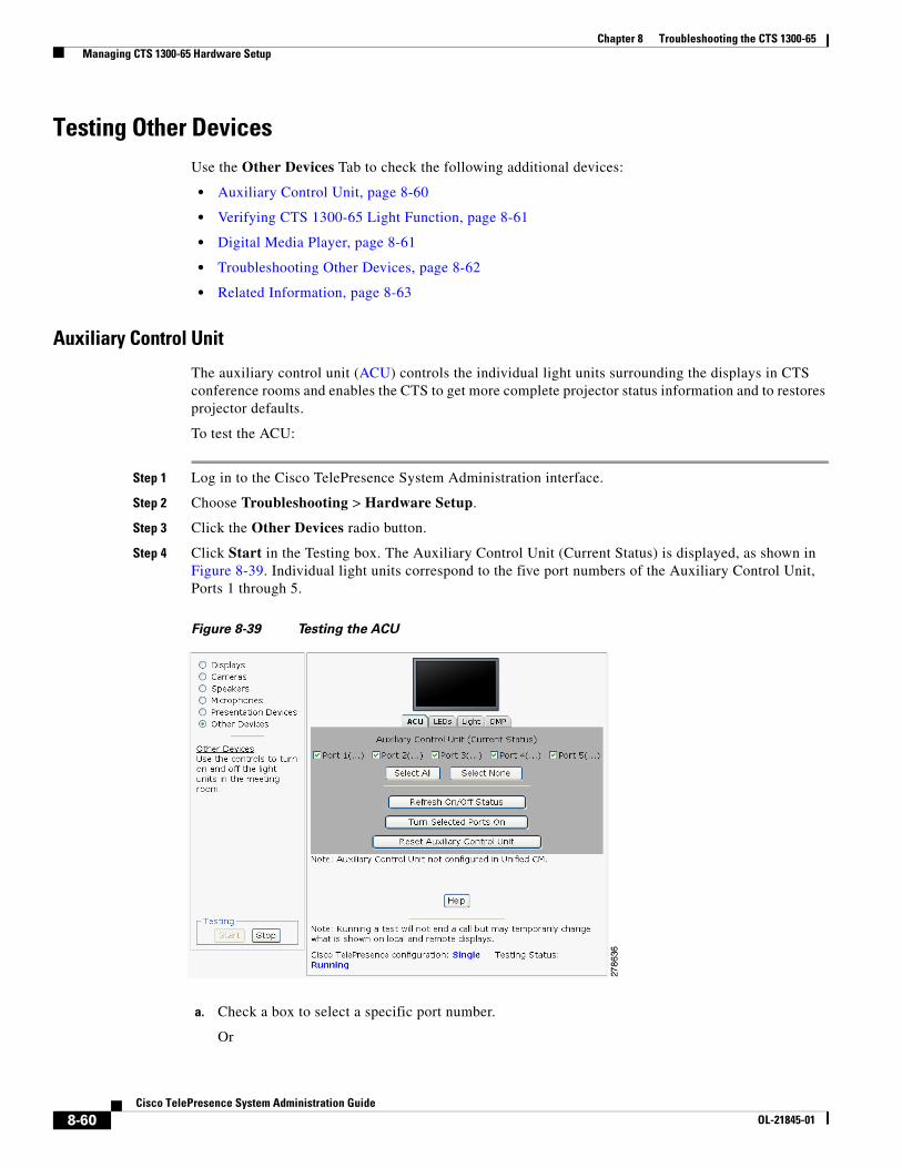
Chapter 8 Troubleshooting the CTS 1300-65 Managing CTS 1300-65 Hardware Setup
Testing Other DevicesUse the Other Devices Tab to check the following additional devices:
• Auxiliary Control Unit, page 8-60
• Verifying CTS 1300-65 Light Function, page 8-61
• Digital Media Player, page 8-61
• Troubleshooting Other Devices, page 8-62
• Related Information, page 8-63
Auxiliary Control Unit
The auxiliary control unit (ACU) controls the individual light units surrounding the displays in CTS conference rooms and enables the CTS to get more complete projector status information and to restores projector defaults.
To test the ACU:
Step 1 Log in to the Cisco TelePresence System Administration interface.
Step 2 Choose Troubleshooting > Hardware Setup.
Step 3 Click the Other Devices radio button.
Step 4 Click Start in the Testing box. The Auxiliary Control Unit (Current Status) is displayed, as shown in Figure 8-39. Individual light units correspond to the five port numbers of the Auxiliary Control Unit, Ports 1 through 5.
Figure 8-39 Testing the ACU
a. Check a box to select a specific port number.
Or
8-60Cisco TelePresence System Administration Guide
OL-21845-01
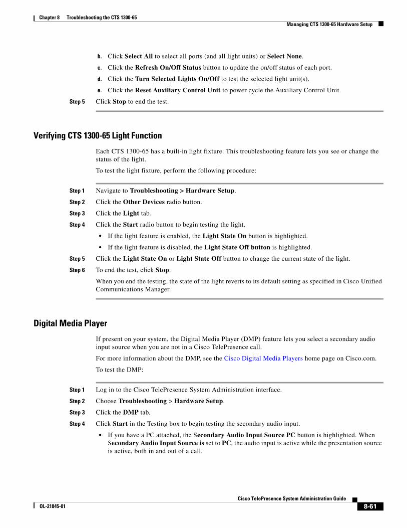
Chapter 8 Troubleshooting the CTS 1300-65 Managing CTS 1300-65 Hardware Setup
b. Click Select All to select all ports (and all light units) or Select None.
c. Click the Refresh On/Off Status button to update the on/off status of each port.
d. Click the Turn Selected Lights On/Off to test the selected light unit(s).
e. Click the Reset Auxiliary Control Unit to power cycle the Auxiliary Control Unit.
Step 5 Click Stop to end the test.
Verifying CTS 1300-65 Light Function
Each CTS 1300-65 has a built-in light fixture. This troubleshooting feature lets you see or change the status of the light.
To test the light fixture, perform the following procedure:
Step 1 Navigate to Troubleshooting > Hardware Setup.
Step 2 Click the Other Devices radio button.
Step 3 Click the Light tab.
Step 4 Click the Start radio button to begin testing the light.
• If the light feature is enabled, the Light State On button is highlighted.
• If the light feature is disabled, the Light State Off button is highlighted.
Step 5 Click the Light State On or Light State Off button to change the current state of the light.
Step 6 To end the test, click Stop.
When you end the testing, the state of the light reverts to its default setting as specified in Cisco Unified Communications Manager.
Digital Media Player
If present on your system, the Digital Media Player (DMP) feature lets you select a secondary audio input source when you are not in a Cisco TelePresence call.
For more information about the DMP, see the Cisco Digital Media Players home page on Cisco.com.
To test the DMP:
Step 1 Log in to the Cisco TelePresence System Administration interface.
Step 2 Choose Troubleshooting > Hardware Setup.
Step 3 Click the DMP tab.
Step 4 Click Start in the Testing box to begin testing the secondary audio input.
• If you have a PC attached, the Secondary Audio Input Source PC button is highlighted. When Secondary Audio Input Source is set to PC, the audio input is active while the presentation source is active, both in and out of a call.
8-61Cisco TelePresence System Administration Guide
OL-21845-01
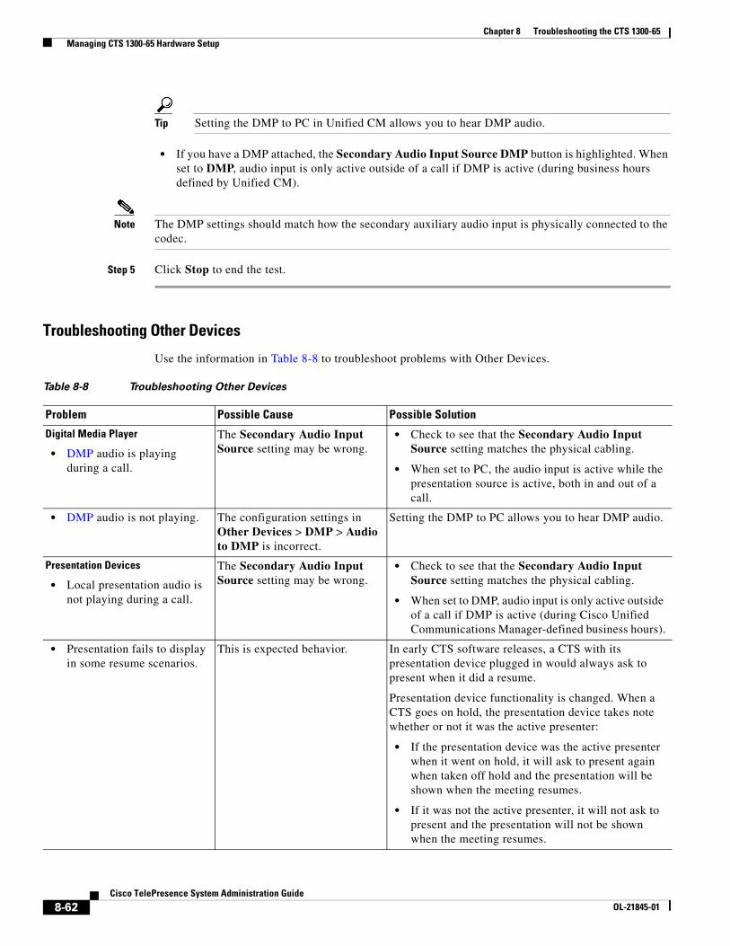
Chapter 8 Troubleshooting the CTS 1300-65 Managing CTS 1300-65 Hardware Setup
Tip Setting the DMP to PC in Unified CM allows you to hear DMP audio.
• If you have a DMP attached, the Secondary Audio Input Source DMP button is highlighted. When set to DMP, audio input is only active outside of a call if DMP is active (during business hours defined by Unified CM).
Note The DMP settings should match how the secondary auxiliary audio input is physically connected to the codec.
Step 5 Click Stop to end the test.
Troubleshooting Other Devices
Use the information in Table 8-8 to troubleshoot problems with Other Devices.
Table 8-8 Troubleshooting Other Devices
Problem Possible Cause Possible Solution
Digital Media Player
• DMP audio is playing during a call.
The Secondary Audio Input Source setting may be wrong.
• Check to see that the Secondary Audio Input Source setting matches the physical cabling.
• When set to PC, the audio input is active while the presentation source is active, both in and out of a call.
• DMP audio is not playing. The configuration settings in Other Devices > DMP > Audio to DMP is incorrect.
Setting the DMP to PC allows you to hear DMP audio.
Presentation Devices
• Local presentation audio is not playing during a call.
The Secondary Audio Input Source setting may be wrong.
• Check to see that the Secondary Audio Input Source setting matches the physical cabling.
• When set to DMP, audio input is only active outside of a call if DMP is active (during Cisco Unified Communications Manager-defined business hours).
• Presentation fails to display in some resume scenarios.
This is expected behavior. In early CTS software releases, a CTS with its presentation device plugged in would always ask to present when it did a resume.
Presentation device functionality is changed. When a CTS goes on hold, the presentation device takes note whether or not it was the active presenter:
• If the presentation device was the active presenter when it went on hold, it will ask to present again when taken off hold and the presentation will be shown when the meeting resumes.
• If it was not the active presenter, it will not ask to present and the presentation will not be shown when the meeting resumes.
8-62Cisco TelePresence System Administration Guide
OL-21845-01
Chapter 8 Troubleshooting the CTS 1300-65 Managing Log Files
Related Information
• For more information about setting up and testing other devices, see the Cisco TelePresence System 1300-65 Assembly, Use & Care, and Field Replacement Unit Guide.
• For more system troubleshooting information, see the Cisco TelePresence System Troubleshooting Guide on Cisco.com.
Managing Log Files
Tip If you are using Internet Explorer, remember to turn off Pop-up Blocker or configure Pop-up Blocker to allow the IP address before capturing system log files.
Use Log Files to view system operation (sysop) log files, Session Initiation Protocol (SIP) messages and log files from the Cisco TelePresence system. Click the appropriate tab at the top of the window to view the following information:
• Sysop Log, page 8-63
• Log Files, page 8-64
• SIP Messages, page 8-65
Sysop LogTo manage sysop messages:
Step 1 Choose Troubleshooting > Log Files.
Step 2 Select the Sysop Files tab to view system operation (sysop) messages, including call information, call statistics, and call errors for the Cisco TelePresence system. There can be up to 20 individual files saved on the CTS, and each file can contain up to 100,000 characters.
• Administration login can be slow when presenting during point-to-point secure calls.
This is expected behavior. Administration CLI login can take as much as 60 seconds during point-to-point secure calls when a hold/resume is performed while presenting.
Tip Other devices automatically shut off when there is no longer a video signal to that device. An on-screen timer counts down the remaining time to shut-down. The amount of time that it takes a device to shut down depends on your Unified CM configuration. Most CTS devices that support PiP shut down in 10 to 15 seconds after the video signal is removed. Devices on the CTS 3000 and CTS 3200 series that have black boxes associated with the auxiliary control take 5 minutes to shut down. See the Product Specific Configuration Layout section of the Cisco Unified Communications Manager Configuration Guide for the Cisco TelePresence System for more information about controlling presentation devices and associated displays.
Table 8-8 Troubleshooting Other Devices (continued)
Problem Possible Cause Possible Solution
8-63Cisco TelePresence System Administration Guide
OL-21845-01
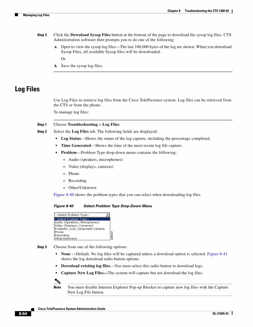
Chapter 8 Troubleshooting the CTS 1300-65 Managing Log Files
Step 3 Click the Download Sysop Files button at the bottom of the page to download the sysop log files. CTS Administration software then prompts you to do one of the following:
a. Open to view the sysop log files—The last 100,000 bytes of the log are shown. When you download Sysop Files, all available Sysop files will be downloaded.
Or
b. Save the sysop log files.
Log FilesUse Log Files to retrieve log files from the Cisco TelePresence system. Log files can be retrieved from the CTS or from the phone.
To manage log files:
Step 1 Choose Troubleshooting > Log Files.
Step 2 Select the Log Files tab. The following fields are displayed:
• Log Status—Shows the status of the log capture, including the percentage completed.
• Time Generated—Shows the time of the most recent log file capture.
• Problem—Problem Type drop-down menu contains the following:
– Audio (speakers, microphones)
– Video (displays, cameras)
– Phone
– Recording
– Other/Unknown
Figure 8-40 shows the problem types that you can select when downloading log files.
Figure 8-40 Select Problem Type Drop-Down Menu
Step 3 Choose from one of the following options:
• None —Default. No log files will be captured unless a download option is selected. Figure 8-41 shows the log download radio button options.
• Download existing log files—You must select this radio button to download logs.
• Capture New Log Files—The system will capture but not download the log files.
Note You must disable Internet Explorer Pop-up Blocker to capture new log files with the Capture New Log Fils button.
8-64Cisco TelePresence System Administration Guide
OL-21845-01
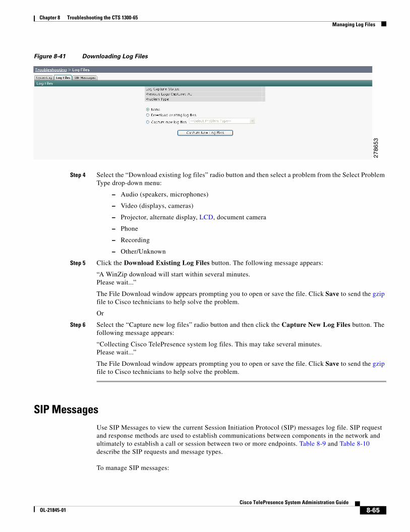
Chapter 8 Troubleshooting the CTS 1300-65 Managing Log Files
Figure 8-41 Downloading Log Files
Step 4 Select the “Download existing log files” radio button and then select a problem from the Select Problem Type drop-down menu:
– Audio (speakers, microphones)
– Video (displays, cameras)
– Projector, alternate display, LCD, document camera
– Phone
– Recording
– Other/Unknown
Step 5 Click the Download Existing Log Files button. The following message appears:
“A WinZip download will start within several minutes.Please wait...”
The File Download window appears prompting you to open or save the file. Click Save to send the gzip file to Cisco technicians to help solve the problem.
Or
Step 6 Select the “Capture new log files” radio button and then click the Capture New Log Files button. The following message appears:
“Collecting Cisco TelePresence system log files. This may take several minutes.Please wait...”
The File Download window appears prompting you to open or save the file. Click Save to send the gzip file to Cisco technicians to help solve the problem.
SIP MessagesUse SIP Messages to view the current Session Initiation Protocol (SIP) messages log file. SIP request and response methods are used to establish communications between components in the network and ultimately to establish a call or session between two or more endpoints. Table 8-9 and Table 8-10 describe the SIP requests and message types.
To manage SIP messages:
8-65Cisco TelePresence System Administration Guide
OL-21845-01
Chapter 8 Troubleshooting the CTS 1300-65 Managing Log Files
Step 1 Choose Troubleshooting > Log Files.
Step 2 Select the SIP Messages tab. The SIP Messages window appears.
Step 3 View a specific type of message in the SIP log file by doing the following:
a. Enter the filter where the SIP Message Type is by typing the name in the field provided. The Filter button is activated.
Or
b. Select the message type from the drop-down menu. The Filter button is activated.
c. Click the Filter button to view the SIP messages of the type you specified.
Step 4 Choose the number of messages to view at one time from the Rows Per Page drop-down menu. You can use the First, Previous, Next, and Last buttons to navigate through the message list with the Navigating Long Lists option. You can also Generate Detailed Message Reports.
Generate Detailed Message Reports
To see additional details associated with a SIP message:
Step 1 Double-click on a SIP message from the list to open the SIP Message Details dialog box. The SIP Message Details dialog box opens containing the message details and Related SIP Messages.
Or
Step 2 Highlight the SIP message and click the Details button. The SIP Message Details dialog box opens containing the message details and Related SIP Messages.
Related SIP Messages
The bottom portion of the SIP Message Details window lists SIP messages that are related to the SIP message that was selected at the top of the window.
To view related SIP message details:
Step 1 Double-click a message in the Related SIP Messages window to see details for that message. SIP Requests and Methods and SIP Response Categories are explained below.
Step 2 Click Close to dismiss this window.
Use the information in the following sections to initiate SIP requests and responses:
• SIP Requests and Methods, page 8-66
• SIP Response Categories, page 8-67
SIP Requests and Methods
Table 8-9 summarizes the SIP requests and methods supported by the Cisco TelePresence System Administration software. The first column lists the RFC that describes the SIP request messages or method.
8-66Cisco TelePresence System Administration Guide
OL-21845-01
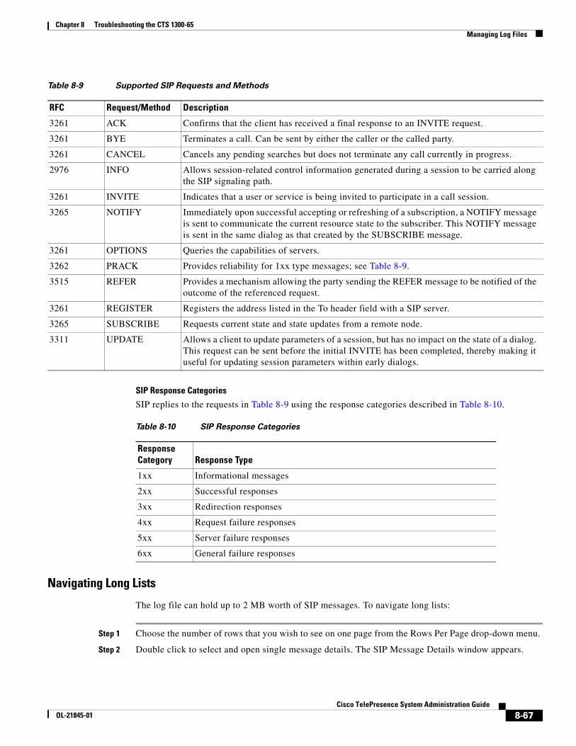
Chapter 8 Troubleshooting the CTS 1300-65 Managing Log Files
SIP Response Categories
SIP replies to the requests in Table 8-9 using the response categories described in Table 8-10.
Navigating Long Lists
The log file can hold up to 2 MB worth of SIP messages. To navigate long lists:
Step 1 Choose the number of rows that you wish to see on one page from the Rows Per Page drop-down menu.
Step 2 Double click to select and open single message details. The SIP Message Details window appears.
Table 8-9 Supported SIP Requests and Methods
RFC Request/Method Description
3261 ACK Confirms that the client has received a final response to an INVITE request.
3261 BYE Terminates a call. Can be sent by either the caller or the called party.
3261 CANCEL Cancels any pending searches but does not terminate any call currently in progress.
2976 INFO Allows session-related control information generated during a session to be carried along the SIP signaling path.
3261 INVITE Indicates that a user or service is being invited to participate in a call session.
3265 NOTIFY Immediately upon successful accepting or refreshing of a subscription, a NOTIFY message is sent to communicate the current resource state to the subscriber. This NOTIFY message is sent in the same dialog as that created by the SUBSCRIBE message.
3261 OPTIONS Queries the capabilities of servers.
3262 PRACK Provides reliability for 1xx type messages; see Table 8-9.
3515 REFER Provides a mechanism allowing the party sending the REFER message to be notified of the outcome of the referenced request.
3261 REGISTER Registers the address listed in the To header field with a SIP server.
3265 SUBSCRIBE Requests current state and state updates from a remote node.
3311 UPDATE Allows a client to update parameters of a session, but has no impact on the state of a dialog. This request can be sent before the initial INVITE has been completed, thereby making it useful for updating session parameters within early dialogs.
Table 8-10 SIP Response Categories
Response Category Response Type
1xx Informational messages
2xx Successful responses
3xx Redirection responses
4xx Request failure responses
5xx Server failure responses
6xx General failure responses
8-67Cisco TelePresence System Administration Guide
OL-21845-01
Chapter 8 Troubleshooting the CTS 1300-65 Testing Audio
Step 3 If there are multiple pages listing log files, click the First, Previous, Next, or Last button to navigate to the desired page.
Step 4 Click the radio button to the left of the table entry, and then click Clear to delete a single error message.
Step 5 Click Clear All to delete all error messages displayed.
Related Information
For more information, see the following documentation:
• Session Initiation Protocol (SIP) home page on Cisco.com.
• Cisco TelePresence System Message Guide
Testing AudioYou can test the system audio in your meeting room and send the results to Cisco Systems technical support for analysis.
Note Audio recordings can be made only while the CTS system is in a call.
To record audio:
Step 1 Choose Troubleshooting > Audio.
Step 2 Click Start Recording Audio to start recording all audio in the local meeting room including audio from remote meeting rooms. Recording will continue up to a maximum of two minutes unless you manually stop recording.
Note Both endpoints will beep periodically during the recording process and when audio add-in participants join the call.
Step 3 Click Stop Audio Recording to stop recording.
Step 4 After you complete the recording and download the results, send the results to Cisco Systems technical support.
Related Information
For more system troubleshooting information, see the Cisco TelePresence System Troubleshooting Guide on Cisco.com.
8-68Cisco TelePresence System Administration Guide
OL-21845-01
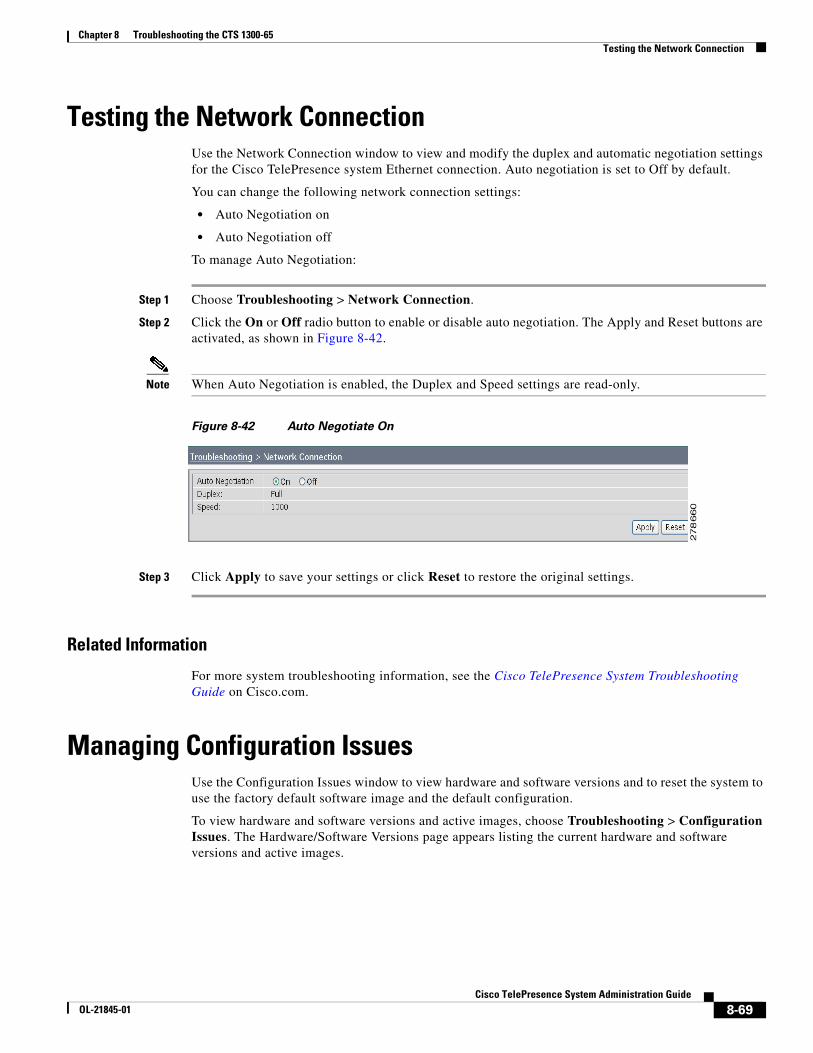
Chapter 8 Troubleshooting the CTS 1300-65 Testing the Network Connection
Testing the Network ConnectionUse the Network Connection window to view and modify the duplex and automatic negotiation settings for the Cisco TelePresence system Ethernet connection. Auto negotiation is set to Off by default.
You can change the following network connection settings:
• Auto Negotiation on
• Auto Negotiation off
To manage Auto Negotiation:
Step 1 Choose Troubleshooting > Network Connection.
Step 2 Click the On or Off radio button to enable or disable auto negotiation. The Apply and Reset buttons are activated, as shown in Figure 8-42.
Note When Auto Negotiation is enabled, the Duplex and Speed settings are read-only.
Figure 8-42 Auto Negotiate On
Step 3 Click Apply to save your settings or click Reset to restore the original settings.
Related Information
For more system troubleshooting information, see the Cisco TelePresence System Troubleshooting Guide on Cisco.com.
Managing Configuration IssuesUse the Configuration Issues window to view hardware and software versions and to reset the system to use the factory default software image and the default configuration.
To view hardware and software versions and active images, choose Troubleshooting > Configuration Issues. The Hardware/Software Versions page appears listing the current hardware and software versions and active images.
8-69Cisco TelePresence System Administration Guide
OL-21845-01
Chapter 8 Troubleshooting the CTS 1300-65 Initiating System Restart
Resetting the System
Caution Once the system is reset, you will have to reconfigure the system. You will be asked twice to confirm your choice to revert to the factory image before software will carry out this request.
Resetting the system can take over two hours to complete.
A system reset results in the following:
• The CTS is reset to the software image as originally shipped.
• All configuration settings are reset to the factory defaults.
If you select to reset the system to use factory defaults, check the Cisco IP telephone for messages during the reset procedure:
• Data in bold blue text indicates where the current system image is located for each codec in the system.
• Locations of the factory image are listed.
To reset the system image to the factory default:
Step 1 Choose Troubleshooting > Configuration Issues. The Hardware/Software Versions page appears listing the current hardware and software versions and active images.
Step 2 Click the Reset to Factory Image and Factory Configuration...and Restart Cisco TelePresence System... button. The system image location is changed and the is system restarted.
Note If a Cisco TelePresence call is in progress, the changes will be made after the call ends.
Related Information
For more system troubleshooting information, see the Cisco TelePresence System Troubleshooting Guide on Cisco.com.
Initiating System Restart
Caution The system will restart immediately, even when a Cisco TelePresence call is in progress.
To restart the system:
Step 1 Choose Troubleshooting > System Restart. The System Restart page appears and the current call status is displayed.
Step 2 Click the Restart Cisco TelePresence System button. The system immediately restarts.
8-70Cisco TelePresence System Administration Guide
OL-21845-01
Chapter 8 Troubleshooting the CTS 1300-65 Troubleshooting Video Quality Settings
Troubleshooting Video Quality SettingsUse the information in Table 8-11 to solve problems that may occur with the video picture on the displays.
Table 8-11 Troubleshooting Cisco TelePresence Screen Resolution Problems
Problem Possible Cause Action
Video picture is good but experiences repeated interruptions.
Video quality setting is set too high.
1. Log into the Cisco Unified CM Administration interface.
2. Verify that the required settings have been made for configuring the video quality. See the Cisco Unified Communications Manager Configuration Guide for the Cisco TelePresence System.
Note Higher bandwidth increases video quality, but may also cause packets to be dropped and video to be interrupted.
Note See the Cisco TelePresence Network Systems 2.0 Design Guide for more information about CTS video quality.
For more system troubleshooting information, see the Cisco TelePresence System Troubleshooting Guide on Cisco.com.
8-71Cisco TelePresence System Administration Guide
OL-21845-01
Chapter 8 Troubleshooting the CTS 1300-65 Troubleshooting Network Cabling
Troubleshooting Network CablingFor all Cisco TelePresence systems, the Cisco Unified IP phone is connected to the primary codec using an Ethernet cable (RJ-45 connector). An RJ-45 connector is also required for the following additional network connections:
• CTS 1300-65—The following cameras are connected to the primary unit:
– Left
– Right
– Center
• An Ethernet cable (RJ-45) connects the primary codec to the user network.
Note For detailed cabling information, see the Routing Power and Signal Cables section in the Cisco TelePresence System 1300-65 Assembly, First-Time Setup, and Field-Replaceable Unit Guide
Table 8-12 contains troubleshooting solutions for network cabling.
Table 8-12 Troubleshooting Cisco TelePresence Network Cabling
Problem Possible Cause Actions
Cisco Unified IP Phone is off.
• Power to the primary unit is off.
• Phone is not connected to the phone port on the primary unit.
• The system does not recognize the phone or it is unregistered.
• The network is down.
• Check the power connection to the Cisco TelePresence System, and verify that the system is turned on.
• Check the cable connection from the primary unit to the Cisco Unified IP Phone. For cabling information, see the Cisco TelePresence System 1300-65 Assembly, Use & Care, and Field Replacement Unit Guide.
• Log into the Cisco Unified Communications Manager administration interface. Click on the IP address and verify phone registration Restore network operation. See the Cisco Unified Communications Manager Configuration Guide for the Cisco TelePresence System for more information.
Cisco IP Phone does not register with the IP network.
• The network cable is not connected to the primary unit.
• The network configuration has not been done or has been done incorrectly.
• Log into the Cisco Unified Communications Manager administration interface and verify that the required settings have been made for configuring the Cisco TelePresence system and Cisco Unified IP Phone.
Cisco IP Phone does not register with the IP network.
• Cisco Unified Communications Manager is down or disabled.
• The network is down.
• Check the cable connection from the primary unit to the network. For cabling instructions, see the Cisco TelePresence System 1300-65 Assembly, Use & Care, and Field Replacement Unit Guide.
• Restart Cisco Unified Communications Manager. See the Cisco Unified Communications Manager Configuration Guide for the Cisco TelePresence System for Cisco Unified Communications Manager configuration instructions.
• Restart the network.
8-72Cisco TelePresence System Administration Guide
OL-21845-01
Chapter 8 Troubleshooting the CTS 1300-65 Where to Go Next
Where to Go NextSee Chapter 12, “Monitoring the Cisco TelePresence System.”
For information about system messages that may appear on the Cisco TelePresence system, see the Cisco TelePresence System Message Guide on the Cisco TelePresence Administration Software Error and System Messages home page on Cisco.com.
Cisco Telepresence phone idle screen does not appear.
Device configuration has not been done or has been done incorrectly.
• Log into the Cisco Unified Communications Manager administration interface.
• Verify that the required settings have been made for configuring the Cisco TelePresence system and Cisco Unified IP Phone. See the Cisco Unified Communications Manager Configuration Guide for the Cisco TelePresence System.
Note For more system troubleshooting information, see the Cisco TelePresence System Troubleshooting Guide on Cisco.com.
Table 8-12 Troubleshooting Cisco TelePresence Network Cabling (continued)
Problem Possible Cause Actions
8-73Cisco TelePresence System Administration Guide
OL-21845-01

Chapter 8 Troubleshooting the CTS 1300-65 Where to Go Next
8-74Cisco TelePresence System Administration Guide
OL-21845-01