troubleshooting guide - prolon · troubleshooting guide version 2 pl-tra-tsg-en 1-877-977-6566...
TRANSCRIPT

TROUBLESHOOTINGGUIDE
Version 2
PL-TRA-TSG-EN
www.proloncontrols.com
1-877-977-6566
17510 Rue Charles, Suite 100, Mirabel, QC, J7J 1X9

Version 2 / PL-TRA-TSG-EN 2
Table of Contents
Table of Figures
Figure 1 - HBEAT light on a M2000 ............................................................................................................................................................ 3
Figure 2 - HBEAT light on a VC2000 ........................................................................................................................................................... 3
Figure 3 - HBEAT light on a NC2000 .......................................................................................................................................................... 3
Figure 4 - HBEAT light in a C1000 ............................................................................................................................................................... 3
Figure 5 - NETSND/NETREC light on a M2000 ........................................................................................................................................ 3
Figure 6 - NETSND/NETREC light in a C1000 .......................................................................................................................................... 3
Figure 7 - NETSND/NETREC light on a VC2000....................................................................................................................................... 3
Figure 8 - Led output lights on a M2000 (RTU) ...................................................................................................................................... 4
Figure 9 - M2000 Switches ........................................................................................................................................................................... 4
Figure 10 .............................................................................................................................................................................................................. 4
Figure 11 .............................................................................................................................................................................................................. 4
Figure 12 .............................................................................................................................................................................................................. 4
Figure 13 .............................................................................................................................................................................................................. 4
Figure 14 .............................................................................................................................................................................................................. 5
Figure 15 .............................................................................................................................................................................................................. 5
Figure 16 .............................................................................................................................................................................................................. 5
Figure 17 .............................................................................................................................................................................................................. 8
Figure 18 .............................................................................................................................................................................................................. 8
Table of Figures .................................................................................................................................................................................................. 2
System Start-Up ................................................................................................................................................................................................. 3
VC2000 VAV Controller .................................................................................................................................................................................... 5
Zone Troubleshooting ..................................................................................................................................................................................... 6
AHU controller troubleshooting................................................................................................................................................................... 7
Network Trouble Shooting ............................................................................................................................................................................. 8
Version 2 / PL-TRA-TSG-EN 3
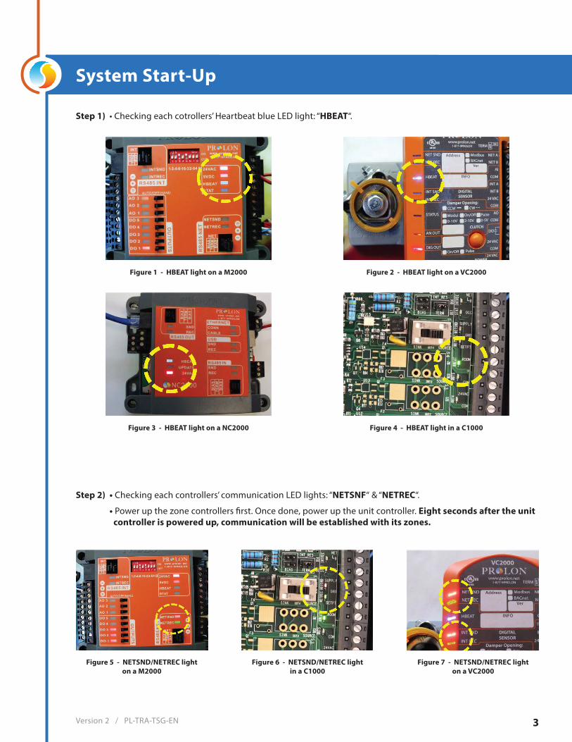
System Start-Up
Figure 1 - HBEAT light on a M2000 Figure 2 - HBEAT light on a VC2000
Figure 4 - HBEAT light in a C1000Figure 3 - HBEAT light on a NC2000
Figure 5 - NETSND/NETREC lighton a M2000
Figure 6 - NETSND/NETREC lightin a C1000
Figure 7 - NETSND/NETREC lighton a VC2000
Step 1) • Checking each cotrollers’ Heartbeat blue LED light: “HBEAT“.
Step 2) • Checking each controllers’ communication LED lights: “NETSNF“ & “NETREC“.
• Power up the zone controllers first. Once done, power up the unit controller. Eight seconds after the unit controller is powered up, communication will be established with its zones.
Version 2 / PL-TRA-TSG-EN 4
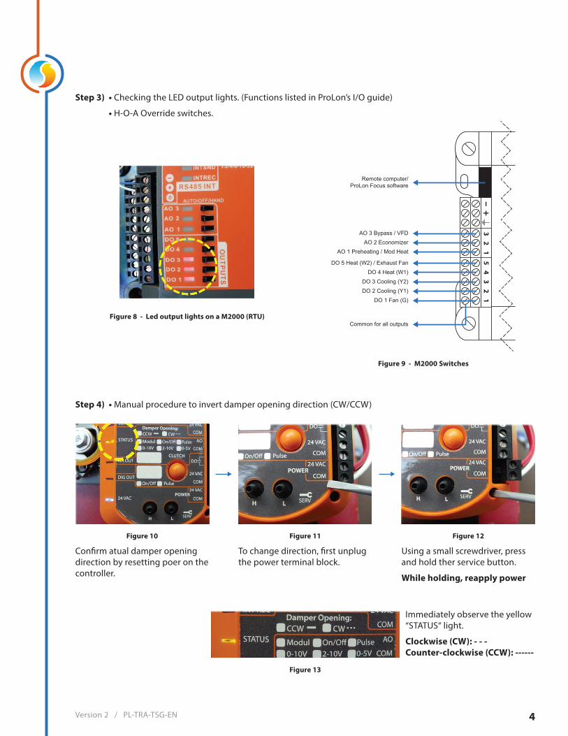
Step 3) • Checking the LED output lights. (Functions listed in ProLon’s I/O guide)
• H-O-A Override switches.
Step 4) • Manual procedure to invert damper opening direction (CW/CCW)
Confirm atual damper opening direction by resetting poer on the controller.
To change direction, first unplug the power terminal block.
Using a small screwdriver, press and hold ther service button.
While holding, reapply power
Figure 8 - Led output lights on a M2000 (RTU)
Figure 9 - M2000 Switches
Figure 10 Figure 11 Figure 12
Figure 13
Remote computer/ProLon Focus software
AO 3 Bypass / VFDAO 2 Economizer
AO 1 Preheating / Mod Heat
DO 5 Heat (W2) / Exhaust FanDO 4 Heat (W1)
DO 3 Cooling (Y2)DO 2 Cooling (Y1)
DO 1 Fan (G)
Common for all outputs
Immediately observe the yellow “STATUS“ light.
Clockwise (CW): - - -Counter-clockwise (CCW): ------
Version 2 / PL-TRA-TSG-EN 5
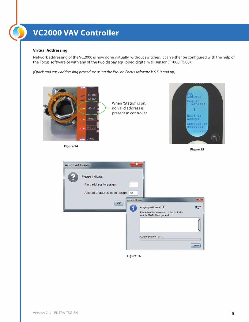
VC2000 VAV Controller
Virtual Addressing
Network addressing of the VC2000 is now done virtually, without switches. It can either be configured with the help of the Focus software or with any of the two dispay equipped digital wall sensor (T1000, T500).
(Quick and easy addressing procedure using the ProLon Focus software V.5.5.0 and up)
When “Status“ is on, no valid address ispresent in controller
Figure 14 Figure 15
Figure 16
Version 2 / PL-TRA-TSG-EN 6
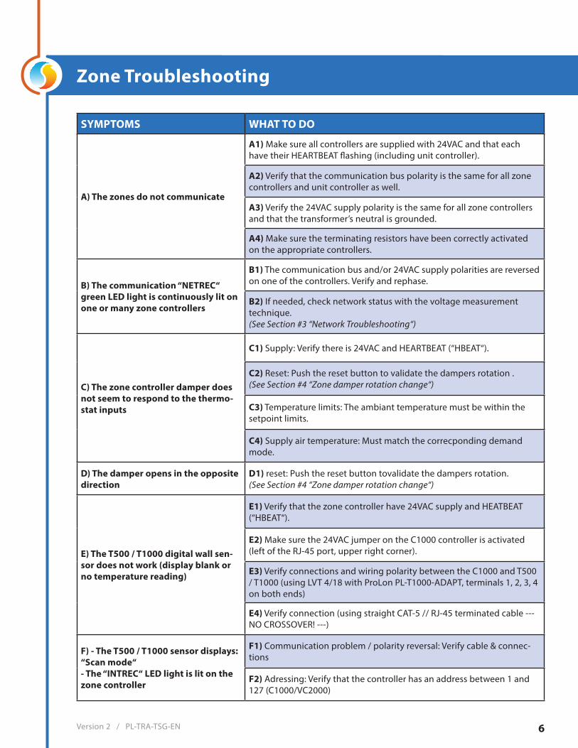
Zone Troubleshooting
SYMPTOMS WHAT TO DO
A) The zones do not communicate
A1) Make sure all controllers are supplied with 24VAC and that each have their HEARTBEAT flashing (including unit controller).
A2) Verify that the communication bus polarity is the same for all zone controllers and unit controller as well.
A3) Verify the 24VAC supply polarity is the same for all zone controllers and that the transformer’s neutral is grounded.
A4) Make sure the terminating resistors have been correctly activated on the appropriate controllers.
B) The communication “NETREC“ green LED light is continuously lit on one or many zone controllers
B1) The communication bus and/or 24VAC supply polarities are reversed on one of the controllers. Verify and rephase.
B2) If needed, check network status with the voltage measurementtechnique.(See Section #3 “Network Troubleshooting“)
C) The zone controller damper does not seem to respond to the thermo-stat inputs
C1) Supply: Verify there is 24VAC and HEARTBEAT (“HBEAT“).
C2) Reset: Push the reset button to validate the dampers rotation .(See Section #4 “Zone damper rotation change“)
C3) Temperature limits: The ambiant temperature must be within the setpoint limits.
C4) Supply air temperature: Must match the correcponding demand mode.
D) The damper opens in the opposite direction
D1) reset: Push the reset button tovalidate the dampers rotation.(See Section #4 “Zone damper rotation change“)
E) The T500 / T1000 digital wall sen-sor does not work (display blank or no temperature reading)
E1) Verify that the zone controller have 24VAC supply and HEATBEAT (“HBEAT“).
E2) Make sure the 24VAC jumper on the C1000 controller is activated (left of the RJ-45 port, upper right corner).
E3) Verify connections and wiring polarity between the C1000 and T500 / T1000 (using LVT 4/18 with ProLon PL-T1000-ADAPT, terminals 1, 2, 3, 4 on both ends)
E4) Verify connection (using straight CAT-5 // RJ-45 terminated cable --- NO CROSSOVER! ---)
F) - The T500 / T1000 sensor displays: “Scan mode“- The “INTREC“ LED light is lit on the zone controller
F1) Communication problem / polarity reversal: Verify cable & connec-tions
F2) Adressing: Verify that the controller has an address between 1 and 127 (C1000/VC2000)

Version 2 / PL-TRA-TSG-EN 7
SYMPTOMS WHAT TO DO
G) One of the digital outputs does not work (Out #1 to #4)
G1) Verify the output state (Red LED).Note that LED remains on evn with output in overload condition.
G2) Output mode selection: Active 24VAC (“SOURCE“) or dry contact (“SINK“). Check for external jumper (VC2000) or position of switch (C1000/VC2000)
G3) Short-Circuit or overload: Unplug output wires and let thermal fuse cool. Fix the problem and replug wires.
G4) Outdoor air or morning warm-up interlock sequence (only DO #3& DO #4 affected): See unit controller settings using ProLon Focussoftware.
H) Analog output does not work(Out #5)
H1) Verify the output state (Red LED).Note that LED turns off when outputs is in overload condition.
H2) Short-Circuit: Verify +/- polarity.
H3) Outdoor air or morning warm-up interlock sequence: See unitcontroller settings with ProLon Focus software.
SYMPTOMS WHAT TO DO
I) the communication LED Lights do not flash (“NETREC“ & “NETSND“)
I1) See “The zones do not communicate“.(Section #1 Zone troubleshooting)
J) Heating or cooling do not ctivate on the air handler unit
J1) Verify the proof of fan.
J2) Keep in mind the default 5 minutes off-delay upon initial system start-up.
J3) Ensure that all zones are communicationg and have the samedemand.
K) - Economizer sequence does not work- Modulating preheating sequence does not work
K1) Outdoor air & supply air sensors: Verify proper connection andpositive reading of temperature.(See Unit Controller using ProLon Focus software)
AHU controller troubleshooting

Version 2 / PL-TRA-TSG-EN 8
Network Trouble Shooting
Galardo Technique (Voltage measurement procedure)
Step 1) Unplug the unit controller (M2000) from the zone network cable.
Step 2) De-activate the terminating resistor jumper from the last zone controller.
Step 3) At any point on the nerwork, perform a DC voltage measurement between each of the A & B (#19 and #18) communication connectors and neutral (#1)
Step 4) Voltage between “A“ and neutral should read about 2.7Vdc.
Step 5) Voltage between “B“ and neutral should read about 2.7Vdc.
Step 6) Should the readings be different, unplug all zones from network and re-plug one at atime while taking new readings until the faulty zone is found.
Figure 17 Figure 18
© Copyright 2018 ProLon. All rights reserved.No part of this document may be photocopied or reproduced by any means, or translated to another language without prior written consent of ProLon. All specifications are nominal and may change as design improvements are introduced. ProLon shall not be liable for damages resulting from misapplication or misuse of its products. All trademarks are the property of their respective owners.
Version 2PL-TRA-TSG-EN