troubleshooting guide 20071205
TRANSCRIPT

Troubleshooting Guide
Revised: 12/5/2007
Corporate Office Manufacturing Plant
Ice House America, LLC Ice House America, LLC 645 Mayport Road 278 S. Highway 319 Atlantic Beach, FL 32233 Moultrie, GA 31768 Phone (904) 241-7535 Phone (229) 890-7000 Fax (904) 241-7976 Fax (229) 890-7040


i
Table of Contents
K Errors...........................................................................................................................1
K2 - Bag system has failed to blow bag open ..............................................................1 K3 - Blower motor overload has tripped.......................................................................1 K5 - Timed out trying to fill transition box.....................................................................1 K6 - Incline, rake, or bin floor motor overload ..............................................................1 K7 - Incline auger has timed out delivering ice (dump boxes have not dumped)..........1
Ice Maker ........................................................................................................................2 Low Pressure Cutout ...................................................................................................2 High Pressure Cutout ..................................................................................................3 Oil Pressure Cutout .....................................................................................................3 Not Running ................................................................................................................3
Cooling Unit ....................................................................................................................4 Freeze-up....................................................................................................................4 Not Holding Temperature ............................................................................................4
Coin Mech/Bill Acceptor ..................................................................................................5 Does Not Accept Bills ..................................................................................................5 Does Not Accept Coins ...............................................................................................6 Does Not Give Credit...................................................................................................7 Incorrect Change.........................................................................................................7
Ice Bin.............................................................................................................................8 Leveler Overload .........................................................................................................8
Bagger Assembly ............................................................................................................9 Dump Box Not Dumping..............................................................................................9 Bulk Only.....................................................................................................................9
Control Cabinet .............................................................................................................10 Wiring Diagram..........................................................................................................10
Water Dispenser ...........................................................................................................11 Calibration .................................................................................................................11 Does Not Accept Money............................................................................................11 Accepts Money but Does Not Dispense Water ..........................................................11

1
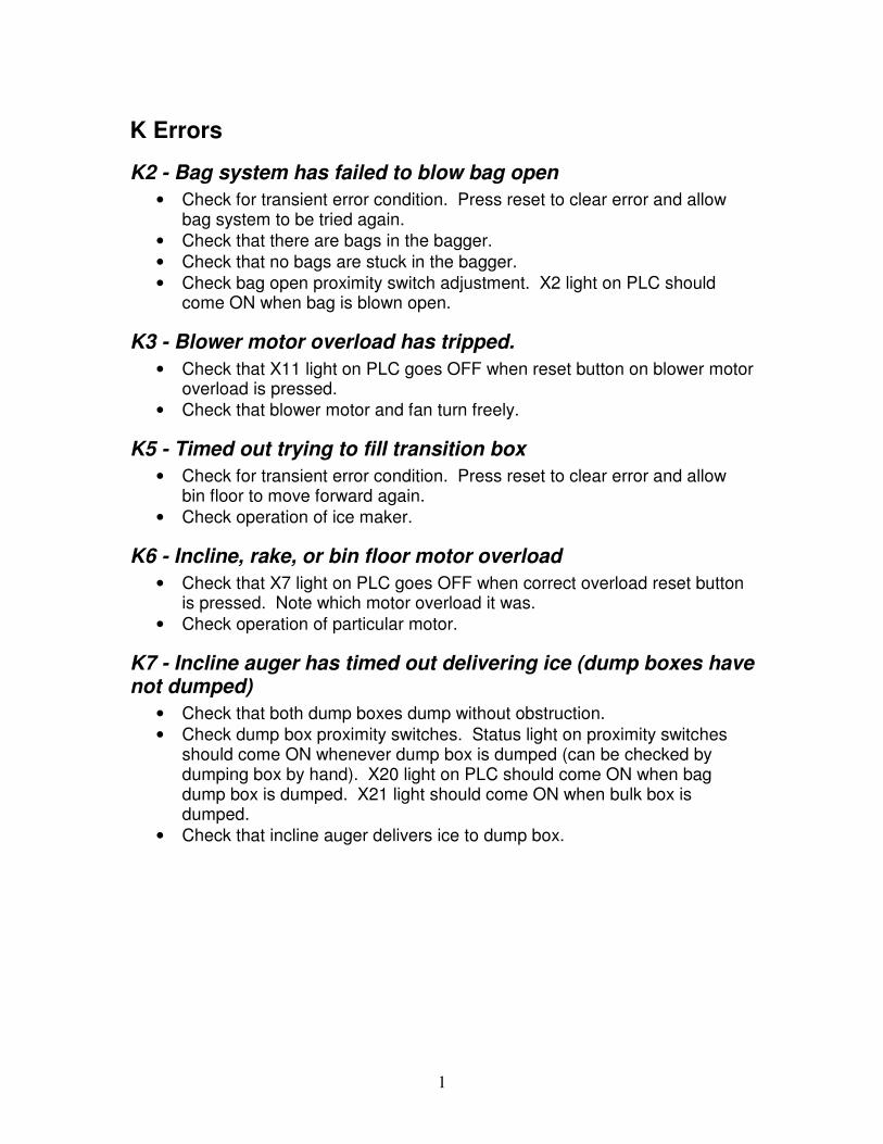
K Errors
K2 - Bag system has failed to blow bag open
• Check for transient error condition. Press reset to clear error and allow bag system to be tried again.
• Check that there are bags in the bagger. • Check that no bags are stuck in the bagger. • Check bag open proximity switch adjustment. X2 light on PLC should
come ON when bag is blown open.
K3 - Blower motor overload has tripped.
• Check that X11 light on PLC goes OFF when reset button on blower motor overload is pressed.
• Check that blower motor and fan turn freely.
K5 - Timed out trying to fill transition box
• Check for transient error condition. Press reset to clear error and allow bin floor to move forward again.
• Check operation of ice maker.
K6 - Incline, rake, or bin floor motor overload
• Check that X7 light on PLC goes OFF when correct overload reset button is pressed. Note which motor overload it was.
• Check operation of particular motor.
K7 - Incline auger has timed out delivering ice (dump boxes have not dumped)
• Check that both dump boxes dump without obstruction. • Check dump box proximity switches. Status light on proximity switches
should come ON whenever dump box is dumped (can be checked by dumping box by hand). X20 light on PLC should come ON when bag dump box is dumped. X21 light should come ON when bulk box is dumped.
• Check that incline auger delivers ice to dump box.

2
Ice Maker
Low Pressure Cutout
• Check that water reservoir has 2 – 2 ½ inches of water while pumping. • Check that incoming water pressure is sufficient to keep 2 – 2 ½ inches of
water in reservoir while making ice. • Check that cycle timer cam turns. Refer to Figure 1.
Figure 1 - Ice Maker Cycle Timer
• Check that locking collar on left end of crusher bar has approximately ¼
inch gap between it and bearing. Refer to Figure 2 and Figure 3.
Figure 2 - Locking Collar Location
Figure 3 - Locking Collar
• Check that micro-switches on cycle timer operate (contacts make and
break) and that roller guides are centered on edge of cam. The switch on bottom puts ice maker into harvest and the switch on left side shuts ice maker down when bin is full or has been switched off. Refer to Figure 1.

3
High Pressure Cutout
• Check that both fan motors run. • Check fan cycle switch settings. • Check that condenser coil veins are not obstructed with trash. Clean if
necessary. • Have a refrigeration technician check system for overcharge. • Have a refrigeration technician check for air in system.
Oil Pressure Cutout
• Check that there is oil in sight glass in bottom of compressor.
Figure 4 - Sight Glass
• Check operation of oil pressure control. When compressor is running and
net oil pressure is in excess of nine pounds (oil pump pressure less suction pressure) and the oil safety control pilot light is red, remove the control cover and jumper the control wires connected to the electronics board leading to the sensors. These are the orange and red wires in the black plastic conduit. If the light remains red, the control is defective. If the light turns green, the sensor or sensor wire is defective. If either device is defective, it is recommended that both controls be changed.
• Have a refrigeration technician check the system if problem is recurring.
Not Running • Check low/high pressure cutout(s). • Check oil pressure cutout. • Check status light on IMS relay on control panel. If ON, press the leveler
motor contactor overload reset button. • Check light on ice maker control box inside ice maker housing. If ON,
check that ice maker ON/OFF switch inside door is ON, bin full switch is OFF, and ambient temperature switch does not have the ice maker OFF.

4
Cooling Unit
Freeze-up
• Check that all fan motors are running. • Check that defrost timer runs. Refer to Figure 5.
Figure 5 - Cooling Unit Defrost Timer
• Check defrost heaters in evaporator. Put unit into manual defrost by
rotating timer until red defrost light comes ON. Refer to Figure 5. • Have a refrigeration technician check system for proper refrigerant charge. • Check unit wiring (wiring diagram inside cover).
Not Holding Temperature
• Check that cooling unit thermostat is set at desired temperature setting. • Have a refrigeration technician check system for proper refrigerant charge.

5
Coin Mech/Bill Acceptor
Does Not Accept Bills
• Check that bill acceptor is powered. Status light on back of bill acceptor should be steady ON or blinking.
• Check for a credit. Bill acceptor will not accept bills when there is a credit. If status light on Y6 relay is ON, press reset button.
• Check bill acceptor status light. If blinking, refer to back of bill stacker or Figure 6 for status code descriptions.
Figure 6 - Bill Acceptor Status Codes
• Check DIP switch settings. Defaults are 1,2,4 and 8 ON if not accepting $5 bills, or 1,2,4,6, and 7 ON if accepting $5 bills. Refer to Figure 7.

6
Figure 7 - Bill Acceptor DIP Switch Settings
Does Not Accept Coins
• Check that coin mech is powered. Activating payout switches should cause coin solenoids to click.
• Clean coin mech. • Re-tune coin mech using the following procedure:
1. Turn off power to PLC (pull PLC fuse or turn off control board breaker).
2. Clean coin path in flight deck with a damp cloth. 3. Lower acceptor part of changer (flight deck). 4. Locate small square hole below price switch. 5. Insert a small screwdriver into hole. 6. Twist the screwdriver, slightly, to short the two pins. 7. Turn ON power to PLC (while still shorting the two pins).

7
8. Remove screwdriver. 9. Insert 2 nickels. They will not be accepted. 10. Insert 2 dimes. They will not be accepted. 11. Insert 2 quarters. They will not be accepted. 12. Press down on the return lever two times. Coin mech should
dispense 1 nickel, meaning it is properly retuned.
Does Not Give Credit
• Check that giving credit with credit button works. X0, X3 or X5 light on PLC should come ON when credit button is pressed. If not, re-init PLC.
• Check that giving credit with coins only works. If so, bill acceptor may be bad. Replace bill acceptor.
• Check operation of X0 relay by exchanging it for a new relay. If new relay works, discard old relay.
• Check voltage pulse on X0 relay terminals 7 & 8 when last coin is inserted. If no pulse, replace coin mech.
Incorrect Change
• Check payout with payout switches. • Check for bent coin or coins stuck together in payout tube. • Replace coin mech.

8
Ice Bin
Leveler Overload
• Check house for extended leveler or ice diverter. Later houses (houses after order number 719) have a leveler that extends to the back of the ice bin.
o On a house without an extended leveler or ice diverter, contact the factory about ordering an ice diverter.
o On a house with an extended leveler or ice diverter, check leveler operation by pressing red button on top of LR relay. Ensure leveler chain moves freely.

9
Bagger Assembly
Dump Box Not Dumping
• Check dump box operation. Manually operate dump box by pressing button on bottom of air value.
• Check for proper air pressure. • Check proximity switch under dump box arm.
Bulk Only
• Check bag inflation proximity switch. • Check for blower motor overload. • Check for proper air pressure.

10
Control Cabinet
Wiring Diagram
Marathon
Power Block
96 98 97 95 96 98 97 95 96 98 97 95 96 98 97 95 96 98 97 95
M5 T1M5 T2M5 T3
M4 T1M4 T2M4 T3M3 T1
M3 T2M3 T3M2 T1M2 T2M2 T3
M1 T1M1 T2M1 T3
DlrNN
Dialer
Coin
common
PB
wblk
blu
To Correct Change Light
Mech
Y17
NO
Y15
Y16
C3
Y14Y13Y11
Y12Y10
C2
Y7Y5
C1
Y2Y00V
Y6Y4Y3Y1C024VACACL N
Leave 10"
Leave 12"
reset
credit
4 A
mp
1 A
mp
1 3 5 7
42 6 8
TRC6800
M5 T1M5 T2M5 T3
M4 T1M4 T2M4 T3M3 T1
M3 T2M3 T3M2 T1M2 T2M2 T3
M1 T1M1 T2M1 T3
DlrNN
Figure 8 - Control Panel Wiring – Ice

11
Water Dispenser
Calibration
Use the following procedure to calibrate water dispenser:
1. Switch PLC toggle switch to the 'TERM' position. 2. Remove cable from display and slide display out of housing. 3. Plug cable back into display. 4. Press 'CHG PRE' key on display keypad to change settings. 5. Press '+' key, repeatedly, to scroll display to '1GalTime'. Time is preset to
0160. 6. Press 'ENT' key to change 1 gallon time. 7. Use ‘←’ and ‘→’ keys to position blinking cursor over digit to change.
Use '+' and '-' keys to increment or decrement digit. 8. Press 'ENT' key to set entered time. 9. Press '+' key to scroll display to '5GalTime'. 10. Press 'ENT' key to change 5 gallon time. Use steps 7 and 8 to set time. 11. Press 'MSG' key to return to main display.
Does Not Accept Money
• Check digital readout on UV light controller. Should read 99. • Check 1A fuse in control cabinet. • Check fuse in UV light controller. • Check for power (110VAC) on L1UV and L2UV on terminal strip in control
panel. If no power, replace UV light controller. • Check for power (24VAC) on C3 on PLC terminal block and green wire on
left side of 1A fuse. If no power, replace 24V transformer.
Accepts Money but Does Not Dispense Water
• Check water dispenser wiring (refer to Figure 9).

12
Figure 9 - Water Dispenser Wiring