trolley mechanical design description
TRANSCRIPT

Trolley Mechanical Design Description
1 Introduction This document describes the mechanical design of the delay line trolley, concentrating on the most important features and referring to the 3-D views of components included here rather than the detailed design drawings which are supplied separately. It should be noted that most of the metal material used in the construction of the trolley is aluminium alloy and much use is made of thread inserts where pieces are to be bolted together. Also most pieces are treated with an alochrome finish.
2 The Trolley The term trolley refers to the complete assembly which runs on wheels inside the delay line pipe. A cut-away view of the trolley inside the pipe is shown in Figure 1. Here three cylindrical structures are clearly shown: the outer cylinder is the delay line pipe, next is the cylinder of the trolley itself, and innermost is the black carbon fibre tube of the cat’s eye. Given the twelve inch diameter of the primary mirror in the cat’s eye, this is the most compact design feasible and alloys ten delay line pipes to be fitted side-by side on a concrete slab only twenty feet across.
Figure 1: Cut-away view of a 3-D representation of the trolley inside the delay line pipe
The trolley comprises two major components: the cat’s eye assembly and the carriage assembly. A larger picture of these assemblies with the principal components labelled is shown in Figure 2. The cat’s eye assembly is a tube housing the optical components and is mounted onto the carriage via flexure legs so that it is free to move along its axis with virtually no friction. The carriage is supported and guided in the pipe by four wheels with resilient tyres. This four point kinematic contact keeps the carriage axially aligned with the pipe, constraining it in four degrees of freedom and thus requiring only piston motion and roll about its axis to be controlled. The carriage also houses the cat’s eye, motor drive and other components and electronics that are required to control the complete assembly. The carriage is actually two halves of a tube joined together along its length. The upper half is the carriage top shell and the lower half is the carriage chassis. This structure allows the cat’s eye and other components to be easily mounted on the chassis and yet retains much of the rigidity of the original tube when re-assembled. The design of the major components and sub-assemblies is presented in more detail in the following sections.

Figure 2: A cut-away view of the trolley and cat's eye assembly shown in the outline of the delay line pipe which carries it. The joining strips between the upper shell and lower chassis of the carriage are visible as are representations of the rear wheel assembly and electronics mounting frame. The cat’s eye assembly is shown with the metrology and science beam paths entering from the right, reflecting off the primary mirror to be focussed onto the flat secondary mirror, reflecting back to the primary mirror again and departing at the right.

3 The Cat's-eye The Cat's-eye has two major optical components, a large parabolic primary mirror, and a small flat secondary mirror located at its focus. A parallel beam of light striking the primary mirror is brought to a focus on the secondary mirror, reflected back to the primary mirror, and returned parallel to its original direction. The relative positions (i.e. shear) of the two beams can be altered by tilting the secondary mirror. The primary and secondary are mounted in structures which are attached to the ends of a very stiff tube. These structures have support points for flexural pivots which attach to the cat’s eye to the trolley chassis.
3.1 Primary mirror cell The primary mirror is mounted in a substantial aluminium alloy cell which is composed of four parts: a back plate, a lower cell half wall, an upper cell half wall and an end ring. With the four parts assembled a complete mirror cell is formed which can be attached to the cat’s eye tube end ring. This construction allows the top wall of the cell to be removed so that the mirror may be inserted or lifted out using a circumferential strap. The mirror cell, shown in Figure 3, incorporates two radial defining adjuster screws 45º either side of the vertical axis in the lower half and a pre-loading screw on the vertical axis in the upper half. This arrangement restrains and locates the primary mirror on the axis of the cat’s eye. To align its axis the primary mirror is manufactured with a flat face 5mm in width around the circumference of the optical surface which is normal to the optical axis to within a tightly controlled specification. When the mirror cell is attached to the cat’s eye tube the primary mirror is pre-loaded from the back plate using three spring-loaded adjusters so that its front face engages against nylon pads mounted on the tube end rings. This arrangement defines the axial position of the primary and aligns its optical axis to be parallel with the cat’s eye tube axis within the manufacturing tolerances. Hence the only adjustment necessary to align the primary to the cat’s eye axis is to set the radial defining screws. The back plate of the mirror cell contains a central boss into which the magnet of the voice coil is located. Horizontally, either side of the boss, two steel rods are fixed and pass through holes in the trolley bulkhead plate onto which the voice coil armature is mounted. The rods are fitted with doughnut shaped resilient pads which limit the free travel of the cat’s eye in the axial direction to approximately ±4 mm. On the same horizontal axis but near the circumference of the back plate are two pads, each with a pair of threaded holes, to which the flexure pivot blocks for the upper part of the flexure leg are attached. Clearance holes in the pivot blocks allow sufficient freedom for the flexure leg to align with the base pivots so as not to over-constrain the flexure pivots when the cat’s eye is mounted to the trolley chassis..

Figure 3: Rear view of primary mirror cell. The removable top section is fitted with a spring definer which pre-loads the mirror onto the two adjustable definers in the bottom wall. The three spring loaded adjusters are visible and are located so that the load passes directly through the mirror to the nylon pads fitted to the cats eye end ring. The centre boss locates the voice coil magnet and the two holes on a horizontal line either side are for fixing the axial limit rods. On the same centreline, two pads near the outer circumference are for mounting the flexure pivots to the top of the rear wishbone leg.
3.2 Cat’s eye tube The cat’s eye tube is formed from a very rigid but light carbon fibre composite tube which is specially manufactured to achieve high axial stiffness with low temperature coefficient. Accurately machined aluminium end rings are glued on to the ends of the tube so that the faces are parallel and normal to the axis of the tube. This gluing operation is carried out in a purpose made jig which holds the end plates in accurate alignment while the glue sets. It is also necessary to ensure that the end rings are not rotated about their axes with respect to each other so that the flexure legs that attach to them are maintained in correct alignment with the trolley chassis. The mass of the cat’s eye tube and end rings is minimised while maintaining sufficient stiffness with the aim of keeping the first axial resonance of the assembly, complete with secondary mirror, above 1 kHz. The carbon fibre tube also provides a

relatively damped structure which should allow the bandwidth of the cat’s eye servo to reach approximately 150 Hz with reasonable stability margins.
3.3 Secondary Mirror Mount
3.3.1 Secondary support ring The secondary mirror support ring is fashioned in two semicircular parts. This is necessary because of the limited distance between the incoming and outgoing science beams. The narrow space available leaves no room for the bridging structure (that would be necessary with a one-piece ring) as well as a secondary focus stage with a tip-tilt actuator. The secondary support ring is shown Figure 1Figure 4.
Figure 4: A view of the secondary stage and its support ring fitted to the end of the carbon fibre tube. The secondary stage mounts between the apexes of the two V-shaped vanes which are part of the secondary support ring. The front wishbone flexure leg is also shown connected to the flexure pivot blocks at either side of the support ring and with the base flexure pivots fitted.
The two-pieces of the support ring are machined from solid and are almost identical. Each semicircle of the ring incorporates a V-shaped vane structure which is stiffened laterally by a web into which a hole is introduced for the metrology beam to pass. The

two halves are conjoined at their circumferences at the top and bottom of the ring and are bridged at the centre by the secondary stage. The ring gains additional stiffness when it is clamped to the cat’s eye end ring and this produces an axially stiff structure without over-constraint.
3.3.2 Secondary stage and mirror assembly The secondary stage is an accurately machined structure housing linear bearings and a cup-shaped receptacle into which the tip-tilt mechanism supporting the secondary mirror is fitted. The cup-shaped receptacle is free to slide in the linear bearings but is spring-loaded against a sapphire ball which forms the tip of a New Focus 8301 Picomotor (a linear piezo-motor). This arrangement provides focussing for the cat’s eye with a resolution of better than 1 µm. Focus position is provided by an RDPE Group D6/05000U LVDT non-contact type encoder clamped to the stage which should provide a local repeatability of better than of ±1µm and a temperature coefficient of ±0.6µm/°F. The secondary mirror is glued directly to the face-plate of a commercial Piezosystem Jena PSH-10 tip-tilt actuator, which can tilt ±5mrad in two orthogonal axes. The tip-tilt stage is mounted directly into the cup-shaped receptacle of the focus stage. Because the parallelism of the tip/tilt actuator face-plate and its rear mounting surface is not specified and the wedge angle of the secondary flat may not be able to compensate for this the mirror must be glued to the actuator face-plate such that lateral tilt (in the direction of a line drawn between the centres of the metrology beam apertures in the secondary support ring) is minimised so as not to use much of the tip/tilt units dynamic range. Any residual tilt in the vertical direction can be removed by tilt adjustment of the whole secondary stage within the secondary support structure.
3.3.3 Cat’s eye flexure legs The complete Cat's-eye assembly just described is mounted in the carriage on two ‘wishbone’ style legs, one at the rear and one at the front. The front wishbone leg, also shown in Figure 4, has to be especially deep so as not to obstruct the science beam. C-flex type flexure pivots are fitted to the top and bottom attachments of the legs so that the cat’s eye is free to move along its axis with no friction and very little damping. The flexure pivots are inserted into precision holes in the legs which have a split and clamp screw arrangement to ensure that the flexure is not distorted when clamped. The flexure pivot blocks mounted to the cat’s eye have a similar clamping arrangement. The spring constant of the flexures is such that the cat’s eye will not quite stand up and will rest against one side of the mechanical stops described later. Pictures of rear wishbone leg, pivot block and flexure might be useful here.
4 The Carriage The carriage is manufactured from a single aluminium tube approximately 8 feet long with an OD of 14 inches and a wall thickness of 0.25 inches. The tube is machined to length and is then prepared for splitting lengthways into two halves. Flats are

machined at intervals on either side of the tube and accurate pairs of holes are drilled into the flats so that each half of the tube will have a hole in the flat that corresponds with the other half. The tube is then split and each lengthways edge is machined internally to accept a joining strip, at either side, that will bridge the small gap between the two halves. The joining strip is accurately machined and drilled with pairs of holes match those drilled in the tube walls. This method of construction allows necessary machining work to be done on the bottom half of the tube, the trolley chassis, while maintaining the necessary accuracy and as much stiffness as possible when the two halves of the tube are separated and joined again. It also makes insertion and removal of the cat’s eye relatively simple and eases access to the trolley drive components and electronics. At this stage of the manufacturing process, holes are machined in the chassis for the wheels and a longitudinal slot is milled to accommodate the linear transformer of the inductive power transfer system. See photographs in Figure 5 and Figure 6.
Figure 5: A photograph of the trolley shell during manufacture showing one of the longitudinal
joints. The holes for the wheels have just been machined.
Figure 6: A photograph of the underside of the trolley chassis showing the slot for the inductive
power transformer. The transverse slots are for transformer supports and electrical connections. The small holes are the fixing screw locations for the glued segments.

4.1 The chassis Most of the trolley’s internal components are mounted on the chassis. It is important that the front and rear wheels are mounted such that contact the pipe at the same radial position and axle alignment is maintained. This helps to minimise the steering effort which may be required to ensure the wheels cross pipe joins at the positions where the pipe sections are matched. The wheels are set at 45˚ to the vertical for equal constraint in the horizontal and vertical directions. The front wheels are limited in size by the need for clear apertures for the light beams, but the rear wheels are larger as more of the carriage and Cat's-eye mass is at the rear. It is also important for the front and rear seating for the cat’s eye pivot flexure mounts are aligned and are co-planar to prevent distortion of the flexures which otherwise would give poorer performance and a limited life. To fulfil the requirements for alignment and to strengthen the shell where the slot for the transformer has been cut as well as to provide additional overall stiffness, especially in torsion, the chassis has segments of aluminium alloy glued to the base (see Figure 7). There are four segments: one for the front wheel and flexure pivot seats, two for strengthening the transformer slot area, and one to accommodate the rear flexure pivot seats, the bulkhead seat, the drive and steering assembly, and the electronics frame. These segments are prepared and roughly machined to a curvature similar to that of the internal surface of the chassis and are then glued and screwed in place using shims to provide a glue-line of suitable thickness. The screws prevent any tendency for the chassis shell to peel away from the segments. Once fixed in place the chassis is set up, aligned and then machined where necessary to provide the accurate seat locations.
Figure 7: The trolley chassis showing the holes machined for the wheels and the four segments forming the machined base to which the trolley components are fixed.
A gap is required between the front wheel segment and the next segment to allow for the extra depth of the front wishbone leg which is necessary to avoid vignetting of the science beam. The remaining segments are separate to allow control of the glue line in a trolley shell which may not be sufficiently straight. A 3-D view of the trolley chassis design with the only the components requiring to be aligned to the trolley axis visible is shown in Figure 8. The height of the front and rear wheel assemblies is controlled as well as their alignment with respect to the trolley axis. The front and rear wishbone legs of the cat’s eye must also be accurately aligned

and their seats co-planar to prevent distortion. The voice coil magnet is mounted on the axis of the cat’s eye mirror cell and the coil itself is mounted on a sub-plate which is inserted through the bulkhead. This arrangement allows the coil to be withdrawn so that the cat’s eye can be inserted or removed from the chassis. Clearance holes in the sub-plate and a spigot ensure that the coil can be centred within the magnet. The trolley drive and steering assembly is located into a machined slot in the chassis and bolted down.
Figure 8: A 3-D view of the trolley design showing the components that need to be aligned to the trolley axis. These are: the front wheel assembly, the front cat’s eye wishbone leg, the rear cat’s
eye wishbone leg, the voice-coil bulkhead and the rear wheel drive and steering assembly.
4.2 Front wheel and flexure seat arrangement The front wheel assembly and front wishbone leg are both fitted the front chassis segment. The arrangement is shown in more detail in Figure 9. The front wheels are 75mm in diameter and 25mm wide. They consist of a machined disk with a central hub counter-bored to accept a standard bearing. A solid synthetic rubber tyre is moulded to the rim and machined to provide an appropriately curved profile. The front wheels are fitted using a shoulder screw which passes through the wheel bearing into an inverted W-shaped sub-frame, machined to fit accurately onto the front chassis segment. The sub-frame is shaped so as to give clearance for the science beam and to ensure the angle between the wheel axes is 90˚. The flexure pivot for the attaching the front wishbone leg to the chassis is necessarily composed of two separate L-shaped blocks which bolt down on to the accurately machined faces of the front chassis segment. The tolerances on the machined components and surfaces are such that any slight misalignment which would produce an over-constraint on the flexure pivots is removed by tightening the upper flexure pivot blocks to the cat’s-eye secondary support ring after the cat’s eye assembly is seated in the chassis.

Figure 9: The front wheel and cat's eye flexure seat.
4.3 Rear cat’s eye pivot flexure seat The rear wishbone leg pivot flexure seat is attached to the fourth chassis segment close to the voice coil bulkhead. Its location is shown in Figure 10 whereas the detail of the component was shown earlier in FIG XXX. Because there is no science beam to contend with the pivot flexures can be mounted on one broad U-shaped bracket. Standard clearance holes are sufficient to allow the cat’s eye to be sufficiently aligned by the front and rear flexure seat attachment points while preventing over-constraint in the horizontal plane. Again, machining tolerances are such that the flexure pivots attached to the mirror cell can be tightened once the cat’s eye assembly is seated.
4.4 Trolley bulkhead The trolley bulkhead is a circular plate cut off at the base where it is attached to the rear segment of the chassis. It has a central boss to locate the voice coil and radial ribs to provide axial stiffness. The outer edge of the plate is bolted to the trolley chassis and also to the trolley top-shell using blocks which can be set to conform to the local non-circularity of the trolley shell. The stiffness of this connection is important in keeping the natural frequency of the piston mode of the bulkhead above the first cat’s eye piston frequency.

The bulkhead plate, shown in more detail in Figure 10 and Figure 11, provides a stiff reaction plate for the voice coil, transmitting reaction forces to the trolley which is a reaction mass. It also serves as a mounting location for the position sensor that measures the differential position between cat’s eye and trolley. The position sensor is a Micro-Epsilon U15 eddy-current sensor with a 15mm range. It is mounted on a cylindrical boss projecting from the bulkhead plate towards the mirror cell such that the sensor fits occupies a space between two ribs of the mirror cell and is approximately 8mm from the rear face of the cell. There are two holes in the bulkhead plate to allow the two steel rods of the cat’s eye axial limit stop arrangement to pass through. Each rod is composed of two parts: a shoulder screw threaded at one end where it screws into the mirror cell and drilled at tapped at the other, and a smaller diameter shoulder screw which passes through the bulkhead plate to screw into the tapped hole in the rod. Two thick washers of resilient damping material fit closely over the smaller shoulder screw either side of the bulkhead so that the shoulder formed by the rod and the shoulder formed by the cap of the screw provide firm mechanical stops.
Figure 10: A detailed view of the voice coil bulkhead, the differential position sensor mounting, rear wishbone leg attachment and the trolley drive and steering assembly.

Figure 11: Side view of the voice coil bulkhead area showing the blocks for attachment to the trolley shell. Also shown is the rear wishbone pivot flexure bracket, the voice coil, the differential sensor mount and one of the cat's eye mechanical limit stops.
4.5 Trolley drive and steering assembly Most of the weight of the trolley is supported by the two rear wheels. These wheels are larger in diameter than the front wheels so that room is available for mounting the drive and steering components directly to the wheel axes. The wheels are identical to the front wheels except that the diameter is increased to 150mm and the drive wheel has a different bore. One rear wheel is driven by a brushless DC servo motor while the other is actively steered by small angles to correct any rotation of the trolley in the pipe. The use of the word ‘steering’ is probably a misnomer but is suitable if one thinks of the delay line pipe being unfurled at the top and laid out flat (like a canal) and the steered wheel as the rudder or steering oar of the trolley. The purpose of the steered wheel, as it becomes inclined to the direction of travel, is to produce a gentle bias force about the axis of the trolley, inducing it to roll. A similar effect is obtained by shifting the centre of gravity of the trolley to one side or the other and this was one method that was considered as a potential steering solution. The trolley drive and steering assembly is based on a single inverted V-shaped frame, shown in Figure 12, which is bolted in position (defined by the slot) on the rearmost trolley chassis segment. The frame is complex because of the space restrictions imposed by the trolley wall and the inclination of the wheel axes. The frame becomes

very rigid when a plate carrying the drive assembly and another carrying the steering assembly are bolted to the sloping sides which are machined to provide the correct angle. The assembly is designed so that either side-plate can be removed in-situ. It is also possible to remove the whole assembly after the removal of just one of the wheels.
Figure 12: The motor drive and steering frame.
Views of the drive and steering assembly are shown in Figure 13 and the two subassemblies are presented in more detail in the following subsections.
Figure 13: The drive and steering assembly mounted to the rear chassis segment and a view of the assembly from underneath.
4.5.1 Trolley drive The trolley drive consists of a Maxon EC60 brushless motor, with integral hall sensors and incremental encoder, coupled to a Spiradrive gearbox providing a 10.25:1 gear reduction and a right-angle output. A special housing is used to mate the motor to the gearbox with access to the shaft coupling contained within. The coupling used is a Huco Flex-B type 538.34 with a torsional stiffness of 915Nmr-1. For a trolley mass of 80kg this places the drive resonance at 73 Hz.

The gearbox housing is bolted to the sub-plate which then bolts to the inverted V frame. This provides torsional rigidity to reaction forces from the drive and any tendency for the long motor housing to vibrate orthogonally to the plane of the plate will be damped by a suitable support. The wheel is clamped to the gearbox output shaft using a collet nut which grips the shaft and the internal bore of the wheel.
4.5.2 Trolley steering A large degree of self-steering is obtained by locating the trolley centre of gravity below the geometric axis. This is a robust control feature because the trolley can only roll so far before side forces generated by the lateral shift in the centre of gravity counteract whatever force is causing the roll. It is therefore impossible to capsize a trolley in the presence of forces due to roughness of the pipe or random misalignment of a wheel. Tests undertaken during the risk reduction phase showed that very large steering angles at one wheel lead to a maximum roll angle of the order of only 30˚ even for a centre of gravity very close to the axis. Self steering is therefore stable but it is not sufficiently accurate for two reasons: firstly the axes of the secondary tip/tilt stage must remain in reasonable alignment to the beam shear sensor, and secondly the trolley wheels must follow relatively narrow track zones to cross the pipe joints where the internal surfaces are aligned. A detailed view of the trolley steering mechanism is shown if Figure 14. The trolley wheel is mounted to a king-pin using the standard shoulder screw method. The king-pin is mounted on flexure pivots and set into a frame attached to the underneath of the steering sub-plate which mounts on the inverted V frame. The pivots allow the wheel to be tilted about an axis orthogonal to its axle, parallel to the sub-plate but offset from the point of contact of the wheel with the pipe wall. The king-pin is connected through a linkage system to the shaft of the steering motor. The connection to the shaft utilises an eccentric cam set into a bearing such that a complete revolution of the motor produces a ±2˚ change of steering angle.

Figure 14: A detailed view of the trolley steering mechanism.
The steering motor is a Servo Systems Inc M-2222-6.0D stepper motor and is magnetically coupled to a Dewit industrial sensors QR30-360B-V-K-5V Quadro-R rotary encoder to provide absolute steering position. This offset of the king-pin axis from the point of contact of the wheel causes a torque on the king-pin when the trolley moves. The torque is resisted by the king-pin flexures and, through the linkage, the holding torque of stepper motor, which is chosen to provide sufficient holding torque when not energized. This design results in very low backlash in the steering chain and only consumes power when a steering correction is required (which is not very often).
4.6 Inductive power transformer Power from the induction cable, which is laid in the bottom of the delay line pipe, is picked up by the inductive power transformer. This consists of a series of 73 ferrite cores (Fair-rite 5978001901) threaded on to a brass tube attached to the underside of the trolley. The brass tube serves both as a mechanical support and the single-turn secondary winding. As the trolley moves, the induction cable is lifted up a short distance, passes through the brass tube which supports it with very little friction and is deposited again on the pipe.

The whole transformer is mounted (partially in a groove) on the underside of the trolley, see Figure 15 and Figure 16. This is done in such a way that it can be removed while the trolley is on the handling gurney without unthreading the induction cable, thus easing the removal of the trolley away from the delay line area for maintenance or adjustment. The transformer is held in a clamp at each end which also serves as the electrical connection to the brass tube forming the secondary winding. These clamps are electrically isolated from the trolley chassis. Two electrically isolated intermediate supports prevent undue droop or oscillation of the transformer tube. The size of the inductive cores is not well controlled and so suitable O-rings or grommets are used to remove any gap between the cores and the clamps.
Figure 15: A side view of the inductive power transformer mounted to the underside of the carriage.
Figure 16: An end view of the transformer mounted to the underside of the carriage. The clearance is sufficient to cope with bends in the pipe and discontinuities at the joins.

Figure 17: End support and clamp of the
inductive power transformer showing the electrical connection to the brass tube.
Figure 18: An intermediate support for the inductive power transformer.
4.7 Electronics chassis and mounting frames The onboard control microprocessor stack, the drive and steering motor controllers, controllers for the Cat's-eye actuators, and power supply electronics are mounted in the space between the voice coil bulkhead and the back plate of the carriage. The primary design consideration is to mount components so that heat can easily be transferred by conduction to the carriage shell and so dissipated to the surrounding pipe. At a pressure of 1mBar the thermal conductivity of the air is very much the same as at atmospheric pressure and so the significant heat transfer conditions are those of conduction and radiation. Both of these are served by distributing heat over as large an area of the trolley as possible. There are also issues of local heat loading affecting some electronic components due to lack of convection and these are addressed on a case by case basis.
4.7.1 PC104 stack The PC104 stack contains all the circuit boards that are required to be connected to the trolley CPU through the PC104 bus. Convenience of construction dictates that other circuit boards should have the same mechanical format where possible even though they do not connect to the bus and consequently the main electronics mounting frame is based on a PC104 size layout. When boards are mounted in a stack they become, to a large extent, inaccessible and so the system devised for the trolley makes use of ‘break-out’ boards on either side of the PC104 stack. This makes for convenience of connecting signals from disparate sources and for ease of monitoring when servicing the trolley. The PC104 stack is mounted in a T-shaped frame at the rear of the trolley (see Figure 19). The frame is made from brass and is thermally coupled to the rear chassis segment at the base of the ‘T’ and to the chassis shell at either side of the ‘T’.
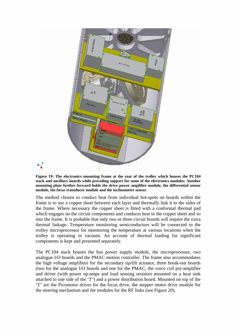
Figure 19: The electronics mounting frame at the rear of the trolley which houses the PC104 stack and ancillary boards while providing support for some of the electronics modules. Another mounting plate further forward holds the drive power amplifier module, the differential sensor module, the focus transducer module and the inclinometer sensor.
The method chosen to conduct heat from individual hot-spots on boards within the frame is to use a copper sheet between each layer and thermally link it to the sides of the frame. Where necessary the copper sheet is fitted with a conformal thermal pad which engages on the circuit components and conducts heat to the copper sheet and so into the frame. It is probable that only two or three circuit boards will require the extra thermal linkage. Temperature monitoring semiconductors will be connected to the trolley microprocessor for monitoring the temperature at various locations when the trolley is operating in vacuum. An account of thermal loading for significant components is kept and presented separately. The PC104 stack houses the bus power supply module, the microprocessor, two analogue I/O boards and the PMAC motion controller. The frame also accommodates the high voltage amplifiers for the secondary tip/tilt actuator, three break-out boards (two for the analogue I/O boards and one for the PMAC, the voice coil pre-amplifier and driver (with power op-amps and load sensing resistors mounted on a heat sink attached to one side of the ‘T’) and a power distribution board. Mounted on top of the ‘T’ are the Picomotor driver for the focus drive, the stepper motor drive module for the steering mechanism and the modules for the RF links (see Figure 20).

Figure 20: Layout of electronics modules at the rear of the trolley.
A ‘shelf’ mounted on brackets further forward, directly over the drive and steering module, accommodates the drive power amplifier module, the differential position sensor electronics module and the focus transducer interface module. For convenience, because it is close to the axis of the trolley, the inclinometer used to detect the roll angle is also mounted on this plate. The space between the drive and steering assembly and the electronics ‘T’ frame is reserved for mounting battery or super-capacitor packs as required.
4.8 Trolley top shell and end plates The trolley top shell is one piece, carries no parts and is fixed to the bottom shell along the sides, at the position of the voice coil bulkhead and also through the end plates at each end of the trolley. It may prove convenient at a later date to make the rear part of this shell removable for easier access to the electronics provided trolley stiffness is not compromised. The end plates stiffen up the ends of the trolley cylinder. The front end plate contains apertures for the science and metrology beams. Also on the front plate are two shallow angle matched optical wedges to deflect the metrology laser beam so that its light does not come to a focus on the secondary mirror at exactly the same place as the science beam and so risk being scattered into it. The rear end plate is covered with

‘Echosorb’ material to diminish reflections of the RF waves travelling down the delay line pipe and serve as a ground plane for the aerials of the analogue and network links.
Figure 21: Trolley front and rear end plates.

5 Appendix I – Photographs of prototype trolley

6 Appendix II – Design calculations & specifications ? Flexure loading ? Motor torque requirement and amplifier rating ? gearbox ratio and torque limits ? stepper motor requirements ? Carbon Fibre tube requirements ? Mass budget ? Thermal budget ? Optical specifications