trix drawingcenter software manual - drummer donniedrummerdonnie.com/archive/dwg to image...
TRANSCRIPT

Trix DrawingCenter™ 5.1 Software Manual
Trix Systems AB Sodra Gubberogatan 8, 416-63 Gothenburg, SWEDEN Phone: +46-31 337 90 90 Fax: +46-31 337 90 99 Email: [email protected]
Trix Systems, Inc. 68 Smith Street, Chelmsford, MA 01824-1711, USA Phone: +1-978-256-4445 Fax: +1-978-256-9593 Email: [email protected]
Copyright Trix Systems AB, 2001-2005. All rights reserved. Rev 7.7, 11/8/05

Legal Notice and Disclaimer
NOTICE
Nothing from this manual may be reproduced, transferred, copied or translated to any language, in any form or by any means for any purpose. Trix Systems does not make any guarantees, neither expressed nor suggested which includes all implied guarantees, that the program will work properly when operated in a careless way or if the system does not meet the system demands. Trix Systems disclaims any responsibility of direct or indirect damage that may be caused by loss of information, computer standstill or any other loss of data or any damage that may be caused by the program.
Licenses and Trademarks
Trix Systems, Trix RasterServer, Trix ImageMaker, Trix Organizer, Trix DrawingCenter and TracTrix are trade marks of Trix Systems AB and Trix Systems, Inc. AutoCAD is a registered trademark of Autodesk, Inc. Microsoft and Windows are registered trademarks of Microsoft Corporation. All other trade names referenced herein are either trademarks or registered trademarks of their respective holders.
Trix Systems reserves the right to change and improve the product. All examples and symbols used in the manual are made up and Trix Systems disclaims all responsibility for any resemblance.
CAUTIONS
File formats: File formats are not standards. Variations of individual file formats exist and formats continuously evolve. Any two files sharing a common file suffix or format may not contain identically structured data. Where the software described in this manual is used to open, display, print, create or otherwise manipulate or transfer files it is the user's sole responsibility to inspect the results in order to assure accuracy and fitness for purpose. Trix Systems cannot be held liable for any omissions, additions or changes in content. The existence of variations in any format means that different software applications and computer systems, regardless of vendor, may display or print the same file differently. We recommend that you establish and employ procedures to assure yourself that the information contained in your files is presented with the integrity and consistency necessary for your purposes.
Other Trix software
If you need the ability to edit raster images and/or convert them from rasters to CAD vectors consider our TracTrix software. To batch convert CAD files to rasters or PDF we offer Trix RasterServer. And to archive and manage your files for easy retrieval we offer Trix Organizer. Details of these and other Trix software can found at our Web site www.trixsystems.com or by clicking on the link at the bottom of the Tools menu in Trix DrawingCenter.

Contents
Section 1: Introduction 2
Understanding the difference between raster and vector files. 2 Installation 3 Moving the license to another computer 3
Section 2: Reference 4
Definitions 4 Table of Functions 4
Section 3: The ‘How-to’ section 8
Starting Trix DrawingCenter 8 Opening files 8 The Folder Browser 8 Scanning 9 Viewing 9 Printing 10 Converting to PDF – saving and emailing 12 Scales 12 Taking Measurements 14 Markup (also known as Annotation or Redlining) 18 Converting raster files to other formats 21 Using Layers 21 Format Specific Features 22 Application Preferences 23 Advanced Functions 25 The Browser version 26 ActiveX Version 27 File associations 27
Appendix 1 – Supported formats 29
Raster formats 29 Vector formats 32 HPGL variants 32
Appendix 2 – Inch to mm conversion table for pen files 33
Appendix 3 – Using the ActiveX component with Visual Basic 34
Index 36

Section 1: Introduction The manual has three sections: Section 1 introduces the software; Section 2 is a table of reference for the functions provided by each icon; Section 3 describes how to use the functions to undertake commonly needed tasks. Items in Sections 2 and 3 are cross-referenced by page numbers.
What does Trix DrawingCenter do? The basic function of a viewer is to open files and display them. Trix DrawingCenter has been designed to do much more than this. It is designed so you can access and use the information in digital engineering drawings in your everyday work. With DrawingCenter you can print, measure, scale, markup and compare multiple files side by side. At the same time it protects the original files from change. It is not an editing software. If you markup the drawing the markup information is saved in a separate file. The original file is never changed.
Understanding the difference between raster and vector files. Trix DrawingCenter will open two different types of images. It is important to understand the difference because each type contains different information. The first type is the raster image. This is the type of image produced when you use a scanner to convert a print to a digital file or when you take a ‘screen shot’ of a computer screen1. It is usually a single layer of information stored in the computer file as rows of ‘dots’. The second type is the vector image. This can be a DWG or DXF file created in a CAD application such as AutoCAD or an HPGL file, usually with the extension .PLT, created by a plotter driver in a CAD application. Vector files can contain more information than raster files. There may be multiple layers and views in a single vector file.
Trix DrawingCenter will enable you to simultaneously open raster and vector files. The tools available will differ according to the type of file opened.
1 Raster files can also be batch produced from CAD files by conversion software such as Trix RasterServer™.
2
Installation The instructions below are for a single user install. If you have purchased a multi-user network license use the instructions in the manual TrixActivationManual.pdf instead.
You should have received four files by Internet download in a zip archive or on a CD-ROM:
DCV5US.exe TSLM5US.exe, TrixDrawingCenterManual.pdf TrixActivationManual.pdf.
There may also be some text files containing additional information.
Run DCV5US.exe to install your Trix DrawingCenter software (you don't have to do this if you already have the demo installed).
Run TSLM5US.exe to install the License Manager.
Start the Trix Systems License Manager application and select the 'New License' button and enter the serial number that was supplied to you.:
Follow the instructions on screen to register the software. Normally activation is automatic, via the internet. If there is any problem with the internet connection you should instead receive an email with an activation code for you to enter manually.
Moving the license to another computer If you need to move the license use the following procedure
1) Use the Trix Systems License Manager on the old computer to 'Deactivate' the current license. Once you have done this you will receive an emailed acknowledgement from us.
2) Please go to http://www.trixsystems.com/sw/TrixDrawingCenterInstallers.zip
to download the latest versions to use for your install. Unzip this archive and use its DCV5US.exe and TSLM5US.exe installers on the new computer. Now the installation is just as for a new install.
3

Section 2: Reference
Definitions Vector files are DWG, DXF and HPGL (PLT).
Raster files are ‘bitmap’ files and include such formats as TIFF, BMP, CALS, JPEG, JEDMICS C4, etc. See Appendix 2 at page 29 for a full list of supported raster formats.
Table of Functions The table below show the functions associated with each tool bar icon. Please note that many tools are also available from the top menu bar. In these cases, icons in the pull down menus are identical to those in the table.
The Control Keys column in the table indicates that additional functionality is available when the control key is used in conjunction with the tool. Three control keys are available:
Ctrl – For raster snapping (see Page 17) or region subtraction (See Page 10).
Shift – To add an additional region to a selected region or force the line tool to draw horizontally or vertically.
Z – To provide a local zoom on the area under the cursor (see Page 29).
The Function column shows keyboard bypass commands that may be used. They are italics.
Not all tools work with all file types. The right hand columns indicate whether the tool works with vector files or raster files.
Many of the tools can also be accessed from the top menu bar. The same icons are represented for menu bar access. Icon Function Control
Keys Vector Files
RasterFiles
See Pg.
Open file. Ctrl O
Save as. Save raster files to other raster formats.
Print. Ctrl P 10
Print Preview. Ctrl F2
Undo. For edits to markup objects only. Ctrl Z
Cut. For markup only. Ctrl X
Copy. Copies selected area to the Clipboard for pasting into another application or a markup element for pasting
4

Icon Function Control Keys
Vector Files
RasterFiles
See Pg.
into another location. Ctrl C
Paste. Paste markup objects from Clipboard. Ctrl P
Select Area. Create regions for copying into another application or for printing.
Shift Ctrl
Toggle markup viewing on or off.
Toggle image viewing on or off.
Zoom in. Hold left mouse button down and drag to define extent of zoom. Release for zoom in. If your mouse has a ‘wheel’ you can also use this for zooming.
9
Zoom out. Click to zoom out to previous magnification.
View entire image. Zooms out to full extent of the image.
Pan. Left click and drag to move image inside window. 9
Lock zoom. Click to disable zoom functions so all images are displayed at the current level of zoom.
Rotate 90° counter clockwise. HPGL
only
Rotate 90° clockwise. HPGL
only
Set scale manually.
Scale from dimension using a known length Z
Measure length of line. Ctrl
Z 14
Measure polygon. Ctrl
Z 15
Measure rectangle. Ctrl
Z 15
5
Icon Function Control Keys
Vector Files
RasterFiles
See Pg.
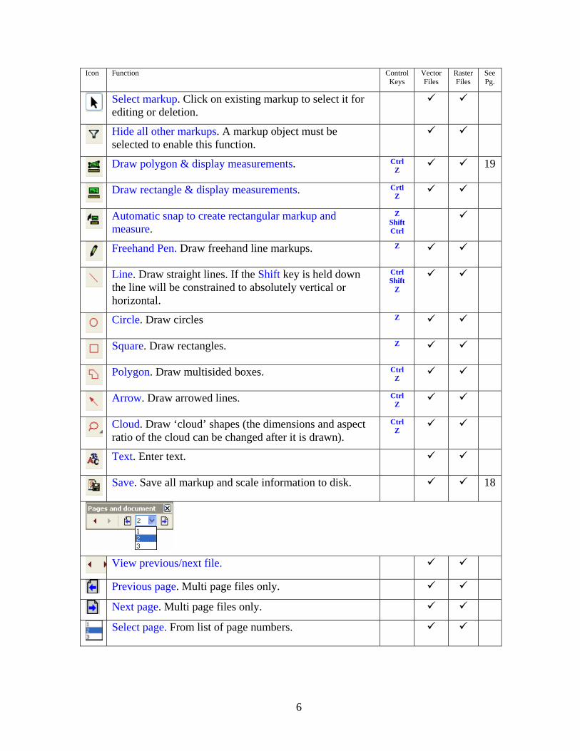
Select markup. Click on existing markup to select it for editing or deletion.
Hide all other markups. A markup object must be selected to enable this function.
Draw polygon & display measurements. Ctrl
Z 19
Draw rectangle & display measurements. Crtl
Z
Automatic snap to create rectangular markup and measure.
Z Shift Ctrl
Freehand Pen. Draw freehand line markups. Z
Line. Draw straight lines. If the Shift key is held down the line will be constrained to absolutely vertical or horizontal.
Ctrl Shift
Z
Circle. Draw circles Z
Square. Draw rectangles. Z
Polygon. Draw multisided boxes. Ctrl
Z
Arrow. Draw arrowed lines. Ctrl
Z
Cloud. Draw ‘cloud’ shapes (the dimensions and aspect ratio of the cloud can be changed after it is drawn).
Ctrl Z
Text. Enter text.
Save. Save all markup and scale information to disk. 18
View previous/next file.
Previous page. Multi page files only.
Next page. Multi page files only.
Select page. From list of page numbers.
6

The following information is displayed at the bottom of the Trix DrawingCenter main window:
7

Section 3: The ‘How-to’ section
Starting Trix DrawingCenter The application is started by going to Start – Programs – Trix DrawingCenter5 – Trix DrawingCenter 5. The installation also places a shortcut named Trix DrawingCenter 5 on your desktop. Double clicking on this will also start the application.
If you have registered a file extension to DrawingCenter, double clicking on any file of this type will start DrawingCenter and open the file for viewing.
Opening files Files from CDs: Before attempting to open files from CD-ROMs you must drag them to a regular drive and un-check the Read-only Property for each file.
In addition to double clicking on files with registered extensions, you can use File – Open from the menu bar or the
icon to locate and open files. Files opened in this way do not require registered extensions. DrawingCenter will examine the contents of the file and determine how to display it.
The Folder Browser Trix DrawingCenter includes a folder browsing tool that enables you to view the entire contents of any folder, one image at a time, without requiring you to use ‘File – Open’.
DrawingCenter does not have to be open to begin this. Select the folder containing the images. Right mouse click and select Browse with Trix DrawingCenter 5. This will open DrawingCenter and display the first image in the folder. In addition a floating menu bar will appear at the top right of your screen.
This menu bar can be dragged to any position on your screen. It contains buttons to control your browsing. Click on the left or right arrows to display the previous or next image in the folder. Click on the movie screen button to play a slide show of all the images in the file. Click again on this button to halt the slide show. To select a new folder to browse click on the folder button.
The check mark button brings up the Browser Settings. Use the File mask to specify the types of files to be displayed, based on extensions. For example, to display only DWG and TIF files you would enter *.dwg; *.tif.
Use the slider bar to set the amount of time for which each image is displayed before the next image is loaded.
The Bowser can also be opened from the selection in the Tools menu.
8

Scanning Trix DrawingCenter enables you to scan files using a desktop scanner. You can then save files as raster files in a wide variety of formats such as TIFF, CALS, JEDMICS C4 and more. Most desktop scanners are supported.
To scan an image, go first to File – Select Source. If your scanner has a TWAIN interface you will see its name listed. Click on the name of the scanner and Select. You need only do this once. Then, when you wish to scan in an image, use File – Acquire Image. Your usual scanner driver software will appear on screen. Scan as usual. After the image has been scanned DrawingCenter will prompt you for a name and raster file format in order to save the image.
Viewing Zooming and Panning
When you open a file, the zoom tool is automatically selected. We refer to this by saying that ‘the zoom tool is currently active’. The icon for the active tool is surrounded by a light blue square.
To zoom in, hold down the left mouse button and drag the mouse. The region defined by dragging the mouse from your start point is indicated by a hatched rectangle.
If your mouse is equipped with a wheel you can also use this to zoom in or out.
When an image is viewed ‘zoomed in’ the pan tool is available. To view parts of the image hidden from view (at the edges of the window) select this tool. Then left click and drag the cursor to move the image left, right, up or down in the window.
Multipage Files
When a multipage file is opened, the first page is shown. To move to other pages use the horizontal arrow icons on the top menu bar. The file identification tab at the foot of the drawing will show the page number and total page count.
If the file is a DWG file created in AutoCAD 2000, or later, the pages correspond to layouts.
The number of files open is limited only by your computer’s available RAM and hard drive caching. As each file is opened, it is displayed and a new file identification tab is created at the foot of the display.
Multiple files opened simultaneously
Each time a new file is opened, it is presented in full view, occupying the entire DrawingCenter window. From the Window menu you then have choices for displaying multiple files:
New Window: The currently active file is opened again in a new window.
Cascade – each open file appears slightly overlapping the previous file.
Tile Horizontally – images are reduced in size to fit horizontal
9

panels. If more than three images are open they are also tiled vertically
Tile Vertically – images are reduced in size to fit vertical panels. If more than three images are open they are also tiled horizontally.
When tiling images, the most recently opened file is are displayed in the top left. Earlier files are displayed downward by column.
Arrange icons – Images that have been minimized to icon representations are gathered together at the foot of the main window.
The currently active file is denoted by the check mark in the file list.
Viewing different areas in the same file Select Window – New Window, as described above, to open additional images of the same file. In this way you can zoom in to details anywhere in a file and view them side by side.
Listing files currently open Select Window – Display Windows. A list of all open files is displayed. By selecting from the lists, files may be closed, brought to the front or minimized.
Copying images into other applications
When an image is open in Trix DrawingCenter, all or part of the image can be copied to the computer’s clipboard. Then you can paste it as an illustration into other applications such as Microsoft Word or PowerPoint.
To do this, select the Select Area tool. Hold down the left mouse button and drag to draw a rectangle around the portion of the image to be copied. Then right click and choose Copy. Switch to the application into which the image is to be inserted and use Paste or Control V to make the insertion. Additional regions can be added to selections by holding down the Shift key in conjunction with the Select Area tool. To subtract a region, hold down the Ctrl key in conjunction with the Select Area tool.
Hiding an image To toggle the display of an image on or off, click on the icon (see also switching Layers on and off as described on Page 21.)
Printing Setting up your printer Open File – Printer Setup. Select the name of your printer in the pull-down name field or click on the Network button to locate a new printer on your network. Set the paper size and orientation, then click OK.
Printing
Click on the icon (or File – Print). A print control box will appear. This provides the options described below.
After setting options, use the Print button to begin printing. The options are:
10

Pages: If the file is a multipage document, this radio button gives you the choice of printing just the current page or all the pages in the document.
Paper Head: By using the appropriate check boxes, you can include the scale, date and time, file name or a user text string at the head of the print. You can also position the heading on the page using the Position settings.
Select the area for printing: Use the radio button to select the entire image, the extent of the image as seen in the DrawingCenter window, or a selected area (see Printing a partial detail below for how to select an area).
Pen selection: Use the Black and White or Color radio button to set use of color in the print. In DWG, DXF and HPGL files, the width of lines can be set according to their original color values using a Pen file (see Page 25). To use a pen file, check the Use pen widths box and click on Pen Widths to select the pen file to be used.
Scale: To use as much of the printable area as possible, select Fit to paper. To use a scale which is in a fixed proportion to the original scale of the image, check the In relation to the original document box. Then enter the ratio that you want to use to scale the image. (For example, to quadruple the size enter 4:1. To halve the size enter 1:2.) When the ratio is entered, the number of printed pages that will be produced is indicated below the scale. By default, DrawingCenter adds a small margin to the edge of each image. To switch this off, check the No margins box.
HPGL and raster files are opened ‘actual size’ – this means that if you print them at a scale of 1:1, they will print just as they were originally intended. DWG/DXF files are much more complex as they do not contain any size information. We say DWG and DXF files are ‘unitless’. Nevertheless DrawingCenter makes an attempt to best establish a size for you. You can view and change the sheet size using the Tools – DWG size/units window.
In the example shown, the DWG file has been assessed to be an ANSI ‘D’ size. If you leave this unchanged, the printing dialog window will assume the image fills a D-size sheet. To change the sheet size, first select the drawing units you wish to use in the left hand pane. Then use the pull-down menu to the right to select the new sheet size.
Printing all images
To print every image open in DrawingCenter, not just the active image, use File – Print All.
11

Hiding markup when printing
Use the markup on/off toggle to display or hide markup before printing. The image on/off toggle can be used in a similar fashion to print out only markup.
Printing a partial detail
To print a detail from an image click on the Select Area tool . Place the cursor on a corner of the region to be printed and depress the mouse button. With the button held down drag the mouse to create a rectangle containing the region to be printed. Click on the icon (or File – Print) and choose Selected Area in the print control box.
Print Preview
Chose (or File – Preview). A new window opens to display the print preview. It has its own menu bar to enable zoom, moving page to page and printing.
Converting to PDF – saving and emailing Instead of printing you can save or email a PDF version of a drawing using File – PDF – Save as file or File – PDF – Send as email.2
Selecting Send as email will create a PDF image as an attachment to a blank email in your email application.
Scales Why scale? Scales relate the real world dimensions of objects depicted in drawings to the size of the objects when the drawing is printed. One of the great advantages of presenting drawings in Trix DrawingCenter is that you can measure lengths, perimeters, and areas in real world units, e.g. millimeters, inches, square yards, dimensioned full scale to the piece to be manufactured or a built. For example, if you want to install carpeting, it is first necessary to determine the square yards of carpet required. Trix DrawingCenter lets you set the scale of the drawing and provides measuring tools to complete the needed calculation accurately. For this measurement to be correct in real world units it is required that the scale of the drawing be set correctly before making the measurement.
Scale need only be set once for each file. You can have Trix DrawingCenter remember the scale (and markups created for the image) by clicking on , the Save markup icon. Caution: the scale may change within a drawing – different parts of a drawing can contain detail
2 The PDF will be a fixe ona l functionality is available by upgrading to TracTrix conversion software. Details can be found at the Trix Systems Web site at http://www.trixsystems.com/tractrix.html.
12

drawn at different scales. Check to see that the scale you have set is appropriate to the detail you are measuring.
Scales work only in drawings that represent a single plane, typically a front, side or top view. Scaling will not operate with respect to drawings presenting isometric (3D) perspectives.
Setting a scale
In general, when you first open a file the measuring tools will produce the dimensions that you would see if you were to measure the physical dimensions of a full size print produced from the file. Unless the drawing in the file is at 1:1 scale you will have to set the scale before taking off measurements. There are two ways to do this. Look at the illustration below.
In this portion of the drawing the scale is shown as ¼” = 1’- 0”. This translates to a scale of 1:48. Click on the
Document Scale tool and enter the scale as shown here. The measuring tools can now be used to take off dimensions (see Page 14).
If no scale is shown look instead for a dimension in the image. In the illustration above a 25’ dimension is visible. Click on the Check Scale tool and draw a line from one of the arrowheads at the end of the 25’ dimension line to the other end. When the cursor is positioned over the arrow tip, use the Z key to zoom in to precisely locate the end point.
Next the document scale dialogue box opens enabling you to enter required distances and units of measurement. Trix DrawingCenter now calculates a scale and presents a box showing the result. In this example the calculated scale is 1:48.09349071 which is most likely an approximation of
13

1:48. To round the drawing scale to 1:48, simply enter 48 in the right hand scale box..
In another example the Check Scale tool might produce a result of 1: 1201.33982541. It’s likely that this would be correctly rounded to 1:1200, reflecting a 1” to 100’ scale.
If there is no visible scale information: Look for known elements in a drawing such as stair treads where the depth is controlled by building codes. Or the width of a door frame. Measure across these using the Scale from Dimension icon and insert the dimension. This can establish a scale that is adequate for your purpose.
Cross checking a scale
Zoom in to any dimension you have found. Select the Measure Length icon. Click once at one end of the dimension on the screen. Move the cursor to the other end of the line and click once more. The measured length will appear. If this is the same dimension as that shown on the drawing your scale setting is correct. (or it could be very close but not exact – you may not have exactly selected the limits when you mouse clicked the ends of the measurement)
Taking Measurements Before taking measurements the appropriate scale must be established - see Page 12. And be sure to read the instructions at the end of this section for using Local Zoom and Raster Snap to speed measurement.
Using the measurement tools
Three measurement tools are available in DrawingCenter: Measure Length, Measure Polygon and Measure Rectangle. Measurements can also be made as you create markup with the .Markup Polygon, Markup Rectangle and Auto Markup tools.
When any one of these measurement tools is selected, the curser becomes a cross hair with the tool icon represented beside it. Specific instructions for using each tool are given below.
The measuring tools are operated as follows:
Measure Length: To begin, select Measure Length by clicking the mouse cursor on the Measure Length icon. Next, position the cross hair cursor at the point where you want to begin measuring and left click. Release the mouse button and move the cursor to the end point of the measurement or to a point where you want to change direction, e.g. a corner, and left click again. Then right click and select End. A window will display the length measurement and associated unit of measure. To change the unit of measure, click the down arrow next to the Unit of Measure field and select another unit of measure. Length
14

measurements are displayed in the most recently selected unit of measure.
Measure Polygon: To begin, select Measure Area by positioning mouse cursor on the polygon shaped Measure Area icon. Position the cross hair cursor at the corner point where you want to begin measuring and left click. Release the mouse button and move the cursor to the next corner point and left click again. Repeat this procedure until you arrive at the final corner point. At this final point, left click; then right click and select Close. The polygon will be closed. A window will display measurements of area, perimeter, height and width and the associated unit of measure. To change the unit of measure, click the down arrow next to the Unit of Measure field and select another unit of measure. Measurements are displayed in the most recently selected unit of measure.
Measure Rectangle: To begin, select Measure Area by positioning mouse cursor on the rectangle shaped Measure Area icon. Position the cross hair cursor at the corner point where you want to begin measuring and left click. Release the mouse button and move the cursor to create a rectangle that matches the corner points of the rectangle to be measured. Then left click the mouse and a window will display measurements of area, perimeter, height and width and the associated unit of measure. To change the unit of measure, click the down arrow next to the Unit of Measure field and select another unit of measure. Measurements are displayed in the most recently selected unit of measure.
Draw Polygon and Measure. To begin, select Create Area by positioning mouse cursor on the polygon shaped icon. Position the cross hair cursor at the corner point where you want to begin drawing and left click. Release the mouse button; move the cursor to the next corner point desired and left click the mouse again. Repeat this procedure until you arrive at the final corner point. Then left click; right click; select Close and a window will display measurements of area, perimeter, height and width and the associated unit of measure. To change the unit of measure, click the down arrow next to the Unit of Measure field and select another unit of measure. Measurements are displayed in the most recently selected unit of measure. The polygon markup is created with a hatched fill. This can be edited – see Editing Markup on Page 19.
Draw rectangle and measure. To begin, select Create Area by positioning mouse cursor on the rectangle shaped markup icon. Position the cross hair cursor at the corner point where you want to begin drawing and left click. Release the mouse button and move the cursor to create a rectangle. Then left click and a window will display measurements of area, perimeter, height and width and the associated unit of measure. To change the unit of measure, click the down arrow next to the Unit of Measure field and select another unit of measure. Measurements are displayed in the most recently selected unit of measure. The rectangular markup is created with a hatched fill.
15

Auto Markup This marks up and measures rectangular areas
that are roughly planar3 to the drawing. To begin, select Create Area by positioning mouse cursor on markup icon. Position the cross hair cursor inside a corner of the rectangle to be marked up, as shown in the illustration to the right, and left click. Release the mouse button.
The application will automatically draw a rectangle of hatched red lines inside the selected rectangular area., as shown in the illustration on the left.
To add another contiguous region, hold down the Shift key continuously. A red cross will appear above the cursor icon to indicate that the next region to be selected will be added to the existing region. Position the cursor in the next region and left click. The new region will be added
to the first, with the whole bounded by the red hatched line, as shown in the illustration to the right.
To complete the process right mouse click and select Create an area object. The dimensions of the entire region will be displayed. When the dimension window is closed the region will be displayed with the usual hatching, as shown in the illustration below.
Using Local Zoom and Raster Snap Trix DrawingCenter provides two functions to help you locate measuring points as precisely and effortlessly as possible:
1) The Z Local Zoom function is enabled for all measurement tools and works in both vector and raster images. As your cursor hovers close to a point that you need to locate more precisely press the Z key. A circular area around the cursor will immediately be magnified. Red cross 3 Planar means having lines that are parallel or at right angles to the sides of the drawing.
16

hairs will indicate the original position of the cursor. Drag the cursor. The cursor will move as you drag the mouse. The magnified local zoom area will remain stationary unless you reach the outer edge of the magnified region, in which case it will move to follow your cursor. When your cursor is positioned over the target point click the mouse just as you normally would to register a point. The magnification disappears as the point is registered.
2) Raster Snap automatically locates a point or corner in a raster image. This means you don’t have to spend time adjusting the cursor position until it sits precisely over the desired point. Instead, as you move close to the point, the cursor will automatically find it and ‘snap’ to it.
The example below illustrates the use of raster snap with the Measure Length tool to measure the length of a wall.
Step 1: With the Measure Length tool selected the cursor is moved towards the corner at one end of the wall.
Step 2: As the cursor approaches the corner the Ctrl key is pressed down. A red square appears around the cross hairs of the cursor. The Ctrl is held down until the red square overlaps the corner point.
Step 3: The user left clicks. Even though the cursor is not exactly over the corner point the raster snap locates the corner point as the origin for the measurement.
Step 4: The user drags the cursor toward the other corner. Approaching the second corner the user repeats the Ctrl key function. The red aperture reappears. As the aperture overlaps the corner the dragged line connecting the origin point to the cursor jumps to fit the wall line.
Step 5: The user left clicks to accept the corner point, then right clicks to End and display the dimension. (In the illustration the dragged line is shown in red. This is for clarity. In
DrawingCenter the line is white.)
Tip: When using Raster Snap do not zoom in too far – it works best when well zoomed out.
Summing Areas of non-contiguous markup If you have two or more non-contiguous mark-up regions on the image you can add up the total area. Shift-select all the mark-up region objects and then Right Mouse Click. Select Properties, then Area. The total area of all the selected regions will be displayed.
17

Setting Aperture
The size of the aperture (the little red square) used for raster snap can be adjusted. With a tool selected, right click and select Properties. Under Tools - Raster Snap increase the setting to have the raster snap seek points further away from the cursor. Decrease it to reduce the search area.
Markup (also known as Annotation or Redlining) How markup is saved Trix DrawingCenter never changes the contents of the files it displays. This protects the source file. However it also means that markup and settings created in Trix DrawingCenter must be saved into a separate file. DrawingCenter names this file identically to the original file but adds the file extension .dw5. For many users the only noticeable effect of this is the appearance of what appears to be a duplicate file in the directory containing the image files. If the original file extension has been associated with DrawingCenter, clicking on either file will open the file. All the markup information is stored in the .dw5 file.
For IT departments that need to serve up engineering drawings to remote clients over the Internet: The Trix DrawingCenter Server product is sold separately for use with the MS IE Browser and allows for unlimited client installs. More information from Trix Systems.
Saving markup
To save markup as you work click on the Save Markup icon or use from the File menu.
Where markup files are saved By default DrawingCenter saves .dw5 files to the same directory in which the original image file is stored. This is usually the most logical place to store the markup data. Using this default storage any other user who opens the image file in their copy of Trix DrawingCenter will also see the markup associated with the image.
It is also possible to designate a separate directory for the storage of .dw5 files. This setting is applied to an individual installation of Trix DrawingCenter. Using this approach you could, for example, maintain your own individualized mark up for your images. You could set up a local directory for your .dw5 files. By making this accessible only to your DrawingCenter other users who open images would not be able to see your markups.
To nominate a directory use Tools – Settings – Markup Directory. Check the box and browse to the directory in which your .dw5 files are to be stored.
Using the markup tools The markup tools are available by clicking on an icon in the markup tool bar. The basic functions of each tool are described in the table on Page 5.
18

Setting the default color and pen width for markup
There are two choices for the default color used by the markup tool. You can either have the color defined by the color for the layer in which you are working (See Page 21) or choose a color to use regardless of layer. Go to Tools – Defaults for markup. Use the radio buttons in the window that appears to select Use Layer Color or Override layer color. If Override layer color is selected the Select color button is enabled. Use this to select the color to use.
In the same window is a setting for the default line width to be applied to markup. Individual markup line width can be altered by selecting the markup on screen and right clicking to see Properties.
Editing markup
After markup is inserted it can be edited by choosing the Select markup icon and then clicking on the edge of the markup to be edited. This selects the markup for further editing. With the multiplicity of options provided it is possible to create virtually any shape you need by starting from the basic markup shapes.
To move the markup drag the mouse.
To change the shape click on a control point (a square box on a corner of a markup element) and drag with the mouse.
To edit right click on a selected markup. The possible edits will vary depending upon the type of markup selected. Options include:
Rotate: The markup is outlined and the cursor positioned at the outer end of a ‘crank’. Drag the mouse to turn the crank and rotate the markup.
Move Side: Enables ‘grabbing’ of a side and moving it by dragging the cursor. The orientation of the line is not changed. To use this function select it. Move the cursor over the line you wish to move. It will change to a double arrowed line. Left click and drag to move the line.
Insert corner: This adds an additional control point to a line. Position the cursor over the line at the point where the insertion is to be made. Right click and select Insert Corner.
Cut: Deletes the markup and places a copy on the clipboard.
Copy: Copies the markup and places a copy on the clipboard.
Delete: Deletes the markup.
Properties: Opens up the Properties window. See below.
Markup Properties The Properties window is tabbed. The tabs presented vary according to the type of markup selected.
Entity Tab: Use this tab to edit layer assignment, color and appearance of markup.
To change the layer to which the markup is assigned use the pull down Layer menu. To add an additional layer click on the Layer button.
19
In the color box radio buttons let you choose the markup color from the color of the layer to which it belongs or individually. If you select to color the markup individually the color choice button is enabled. Use this to select a color.
If the markup is a closed entity (i.e. it is a continuous line with no end points) Fill choices will be available along with Pick color and Pick fill buttons. Select Transparent to have the underlying image visible through the markup. Select Contour to have the fill appearance applied to the bounding line surrounding the markup. Use the Line Width box to set the width of line markup or the bounding line in the case of closed entities.
Use the Area button to display the area, perimeter, maximum height and breadth for rectangular and polygonal markup with measurement. (Set the scale first – see Page 12.)
Tools Tab: The settings in this tab apply universally and not to a specific markup or file. The Aperture setting determines how closely you must position the cursor to the perimeter of a piece of markup in order to select it.
Text Tab: Edit markup text here. To change the font or font size click on the Font button.
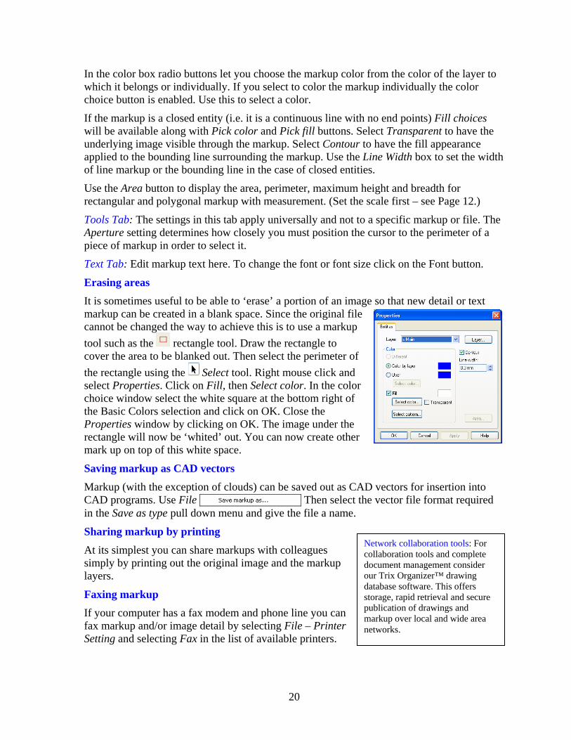
Erasing areas
It is sometimes useful to be able to ‘erase’ a portion of an image so that new detail or text markup can be created in a blank space. Since the original file cannot be changed the way to achieve this is to use a markup tool such as the rectangle tool. Draw the rectangle to cover the area to be blanked out. Then select the perimeter of the rectangle using the Select tool. Right mouse click and select Properties. Click on Fill, then Select color. In the color choice window select the white square at the bottom right of the Basic Colors selection and click on OK. Close the Properties window by clicking on OK. The image under the rectangle will now be ‘whited’ out. You can now create other mark up on top of this white space.
Saving markup as CAD vectors Markup (with the exception of clouds) can be saved out as CAD vectors for insertion into CAD programs. Use File Then select the vector file format required in the Save as type pull down menu and give the file a name.
Sharing markup by printing Network collaboration tools: For collaboration tools and complete document management consider our Trix Organizer™ drawing database software. This offers storage, rapid retrieval and secure publication of drawings and markup over local and wide area networks.
At its simplest you can share markups with colleagues simply by printing out the original image and the markup layers.
Faxing markup If your computer has a fax modem and phone line you can fax markup and/or image detail by selecting File – Printer Setting and selecting Fax in the list of available printers.
20

Emailing a .dw5 file
If you have colleagues with their own copies of DrawingCenter and access to the same original image file you can share markup with them by simply emailing the .dw5 file to them and asking that they place it in the same directory as the image file. Once this is done they will see your markup in DrawingCenter when they open the original image file.
Converting raster files to other formats Saving a raster image in another raster format
Depending on the format of the original raster image opened in DrawingCenter you may be able to save it other raster formats. Use File – Save raster as. You will be presented with a dialog box. Select the new raster format and enter a name and location for the new file. Note: The newly created file does not become active in DrawingCenter. If you wish to view and markup the new file you will have to use File – Open to locate and open it first.
Trix DrawingCenter does not provide raster to vector conversion This is offered in our TracTrix™ raster to vector conversion software. Visit www.trixsystems.com for more information.
Choosing raster image formats To save a raster image to send to a recipient who does not have Trix DrawingCenter try using one of the following formats when you create the image:
TIFF Group 4: This can be opened in Kodak Imaging or Windows Picture Viewer.
PNG: This can be opened in most Web Browsers.
PDF: This can be opened in Adobe Acrobat Reader.
Using Layers Layers enable elements of a displayed image to be switched on and off for viewing or printing. An analogy might be drawings on transparent sheets placed one on top of the other. Removing a sheet is then equivalent to switching off a layer.
Two distinct types of layers can exist in files opened in Trix DrawingCenter. Vector layers contain markup created by Trix DrawingCenter. DWG layers contain images that were originally created in the DWG or DXF file being displayed.
Vector layers can be created and viewed in any file that Trix DrawingCenter is capable of opening. DWG layers can only be viewed in DWG or DXF format files.
Layers are switched on of off depending on what is to be displayed or printed from each file.
21

Markup (vector) Layers
When a file is first opened in DrawingCenter a single empty markup layer is created. This layer is called the Base layer. The default color for markups made in this layer is blue. Additional layers can be created and the color used to display markups in each layer can be changed. Only one layer can be active at a time (the active layer is the one in use for making markups). The name and color for this layer is displayed at the bottom right of the DrawingCenter window. An ‘L’ appears in the square that indicates the active color.
To add a new layer right click on the layer name to the left of the colored square. Select Properties. In the Layer window select Create New. A new layer will be created with the temporary name No Name. Insert the cursor at the right hand end of the text of No Name and select the text. Key in the name you wish to give the new layer.
To change the color used for markups in a new or existing layer from the Layer window select the name of the layer and click on Change. In the Change Layer window click on Select color. Select the color you require and click on OK. The name of the layer may also be changed in the Change Layer window.
To select the layers to be visible right click on the layer name to the left of the colored square. Select Properties. In the Layer window use the check boxes to the left of each name to select the layers you want to be visible.
To select the active layer open the Layer window and click on the radio button next to the name of the layer to make active.
To toggle all markup on or off click on the icon.
Layers in DWG and DXF files Layers in DWG and DXF files are determined in the original file. While they cannot be altered in DrawingCenter you can select those layers you wish to view. Select Tools – Layers. In the Layers window click on the DWG tab to display the layers that exist in the DWG or DXF file. Use the checkboxes to select those layers you wish to view. Then click on Apply. There are also See all and Hide all buttons.
To save a selection of layers for repeat use click on the Save in button under Save Layers. This will create a file containing the selection. This file may be given any name you choose. To reuse a layer file click on the Edit button and select the file you require.
Format Specific Features
22

DWG/DXF format specific features
To display the x-refs and SHX fonts called for in the active DWG or DXF file use Tools – Display DWG SHX/X-ref mapping.
X-Refs (external references) in DWG/DXF files DrawingCenter will call in externally referenced files. These are files that are entirely separate from the file being opened. The images contained in these files are displayed inside the main image displayed by DrawingCenter. When looking for x-ref files, DrawingCenter will:
What are SHX fonts? These are fonts used only in CAD design. The fonts are not stored in the DWG file. If you do not have the required SHX fonts Trix DrawingCenter will make a substitution.
1. Look for the file using the absolute path specified in the source DWG file;
2. If not found, look for the file using the specified path applied relative to the directory now containing the source DWG (for x-ref's with filenames like ..\..\x-ref.dwg)
3. If still not found look for the x-referenced file in the directory now containing the source DWG file.
Note that only x-refs called directly from the original DWG file will be displayed. X-refs called from x-refs will be ignored.
Displaying fonts correctly in DWG/DXF files DrawingCenter will attempt to use any TrueType or SHX fonts called by the file. If a font is not available a substitution will be made.
Views in DWG/DXF files When a DWG or DXF file is displayed tabs at the foot of the display window enable selection of Model Space, Limits, ‘As saved’ and Layout views.
Editing CALS headers
To edit the header information in a CALS file start the folder Browser using Tools – Browse.
Click on the button in the browser menu bar. This will display the CALS header and permit editing or adding new fields. This feature is only available when a CALS format file is opened.
Rasters - format specific information Inversion and Mirroring: Images can be inverted and mirrored by selecting Tools – Raster Functions.
Rotation: Use the and icons to rotate raster images 90° counterclockwise or clockwise.
Application Preferences The general preferences for the application are set from Tools – Settings.
23

Default Unit
Select units using the pull down menu. This determines the units for displaying coordinates. It also sets the default units for measurements. However you can still switch between metric and imperial units in the measurement results window.
Defaults when opening a file Rotate CALS files: Automatically rotates CALS format files ninety degrees on opening. This adjusts for the orientation often seen in CALS files.
Show markup: When checked the application defaults to opening files showing any markup associated with the file. This is the equivalent of toggling the Show markup on. This toggle remains active even if the default is set to open files without markup visible.
Ask for missing X-ref file in DWG/DXF: DrawingCenter automatically looks for any externally referenced files in DWG and DXF files. These are additional files called by the DWG or DXF which contain images to be displayed inside the file being opened. Check this box to be prompted if any x-ref files cannot be found. See Page 23 for information on how Drawing Center looks for x-refs.
Ask for missing font or SHX files in DWG/DXF: DrawingCenter looks for the TrueType and SHX fonts called up by DWG and DXF files. Check this box if you wish to be prompted when a font is not available for display. (DrawingCenter substitutes a default font when the originally specified font is not available). See also the entry below.
DWG/DXF settings Dark Background: If checked DrawingCenter defaults to displaying DWG and DXF files against a black background.
Black/White: Check this to display all lines as black on white or white on black.
Pen widths set by pen file: To display lines in DWG and DXF files with widths read from the active pen file check this box. Otherwise all lines will displayed with a uniform width, regardless of their color.
Font files directory
Drawings created in AutoCAD often use SHX fonts in addition to, or instead of, TrueType fonts. SHX fonts are not stored in the Windows operating system. If you wish to have them display correctly in DrawingCenter you must ‘point’ the software to the directory that stores the SHX fonts. To do this use Tools – Settings. Check the box for Use font catalog for DWG/DXF drawings. Then click on the … button to browse to the directory where the SHX fonts are stored. The path to the directory will then appear to the right of the check box.
Fast printing By default this should be checked. However some printer drivers (such as Ricoh’s Plotbase) may not support this. If you experience difficulty printing try un-checking this box.
24

Markup directory
To nominate a single directory use Tools – Settings – Markup Directory. Check the box and browse to the directory in which your .dw5 files are to be stored. If you select this option the .dw5 files will not be stored in the same directory as the files they mark up.
Advanced Functions Setting up a Pen file The line work in DWG, DXF and HPGL files is usually created in a variety of colors. This makes it easy to distinguish between design elements on screen. It you make a print on a monochrome output device the colors distinctions are lost. To recreate the distinctions it is a common practice to substitute varying line widths for the varying colors. Trix DrawingCenter uses Pen files to provide this functionality.
Each color used in a CAD file is described by a color name and a number. The number is referred to as the color value. A file can contain from one to 255 different colors. Color value 1 is red, Color value 2 is yellow, Color value 3 is green, etc. To enable you to substitute line widths for colors Trix DrawingCenter creates a simple file containing widths. The first line contains a width for color 1, the second for color 2 and so on. So a file containing the rows:
16 25 35….. converts Color 1 (red) lines to 0.16mm wide in a print, Color 2 (yellow) to 0.25mm, etc.
To set up a pen file select Tools – Pen widths. The pen width editing window will open. It shows color values, the color for each value and the line thickness for the pen file currently in use by DrawingCenter. To change a width value place you cursor over it, click once and then select Edit. Enter the width value in millimeters (for a conversion table between mm and inches see Page 33). When you have finished you can either save the changes to the existing Pen file or save it as a new Pen file with a different name.
Customizing Toolbars Use View – Toolbars – Customize to create your own toolbars and set Keyboard commands for frequently used functions.
File Properties - information about a file The file name, type, size and the path to its location for the active image are displayed above the DrawingCenter image window. Additional information can be found by using File – Properties. The Properties window displays information about the entities in the drawing and their dimensions.
DDE Commands Trix DrawingCenter can be controlled using the following DDE commands to open files, print them and close files.
#Open(File name[;File2;File3;...]) Opens one or many files in DrawingCenter
25

#Close([File name]) With no filename all files will be closed.
#Exit() Exit DrawingCenter
#Print(Filename;Scale;Printer;Paperhead;Scaleinfo;Showname;Time;Textinfo;Text)
Filename File to print
Scale 0=Fit(default), 100=1:100
Printer "Printer name"
Paperhead 0=No, 1=Yes
Scaleinfo 0=No, 1=Yes
Showname 0=No, 1=Yes
Time 0=No, 1=Yes
Textinfo 0=No, 1=Yes
Text "User text"
Examples of how it could look in the Explorer:
Open: #Open(%1)
Print: #Open(%1)#Print(%1)#Close(%1) // Default printer and fit to page and no paperhead info
Printto: #Open(%1)#Print(%1;1;%2)#Close(%1) // Selected printer, 1:1 no paperhead info
The Browser version Installation When you install Trix DrawingCenter a version of the software is installed by default for use in the Microsoft Internet Explorer Web Browser. This will enable you to view files served using the HTTP method. For example, http://www.someserver.com/drawing.dwg will launch the Web Browser version of DrawingCenter and display the file drawing.dwg in a DrawingCenter window inside the IE Browser.
An example of a Web page created to serve drawings to a Browser may be seen by selecting Start – Programs – Trix DrawingCenter 5 – Web page with DrawingCenter 5. Look at the source HTML for this example to see how the page is created.
Differences from the standalone version In the Web Browser version only a single image may be viewed at one time. It is not possible to save markup in this version. To save markup from a Browser you should upgrade to Trix Organizer software.
26

ActiveX Version Installation The .ocx file is automatically installed when you install Trix DrawingCenter. It is named DCV5x.ocx and is located in the Program Files\Common Files\Trix Systems folder.
Commands Trix DrawingCenter/X is intended to be a more or less self-running ActiveX component. Add it to a dialog and then use that dialog in a CFormView. What you need to do then is to call SetMainToolbar( TRUE ) to enable the toolbar, where the zoom, pan, etc. tools are available.
You can also turn on or off the annotation/redline toolbar and let DC/X have its own menu bar. Finally call SetFilename to open a file and display it. Once the file is opened DC/X will be self running and lets the user zoom, pan, print etc. without you having to write any extra code to handle this. Calling SetFilename( "" ) will close the current file.
You can control printing using: Print(LPCTSTR printer, SHORT scale, SHORT paperhead, SHORT scaleinfo, SHORT filename,
SHORT time, LPCTSTR text, SHORT dialog)
You first load the file (using the Filename property) and then call Print with the parameters you want, as follows: LPCTSTR printer - Name of printer to print to
SHORT scale - Print to specific scale. 0 = fit to page, 100 = 1:100, etc.
SHORT paperhead - Print paper head (1 - Include, 0 - Omit)
If paperhead = 1 then you can decide what to print in the heading, as follows: - SHORT scaleinfo - Print scale info. 0 = No, 1 = Yes.
- SHORT filename - Print file name. 0 = No, 1 = Yes.(so this isn't the text of the filename - it's simply the flag to include/exclude the name.)
- SHORT time - Print time of printing. 0 = No, 1 = Yes.
- LPCTSTR text - Extra text to print in heading.
SHORT dialog - Display print dialog. 0 = No, 1 = Yes.
Trix Systems maintains a library of additional ActiveX methods. Licenses to use these can be purchased on an as-needed basis. Send an email describing the functionality you require to [email protected].
File associations To register a file extension so that it automatically opens in DrawingCenter use Start- Programs – Trix DrawingCenter – Registration of file types. Check the box Other file type and enter a 2 or 3 character file extension. This is called a file association.
To remove an association use the Folder Options in the Windows Control Panel (this is part of the
27

Windows operating system, not a part of Trix DrawingCenter). Click on File Types. Select the file extension to be changed and use the Change or Restore buttons.
28

Appendix 1 – Supported formats
Raster formats The following raster export formats are currently supported by Trix DrawingCenter. If READ ONLY, the file can be used as a raster input but not output.
Raster Description Usual Extension
Supports Multipage?
Supports color?
C4 JEDMICS C4 No No
CALS Type 1 CAL No No
CALS Type 2 C2 No No
CALS Type 3 NIF Yes No
DjVu (READ ONLY) DJV No Yes
Dr. Halo CUT No Yes
Enhanced Compressed Wavelet ECW No Yes
EPS (Encapsulated PostScript) EPS No Yes
EPS (Encapsulated PostScript – embedded TIFF File) (READ ONLY)
EPS No Yes
Exif JPEG JPG No Yes
Exif JPEG 4:1:1 JPG No Yes
Exif TIFF – no compression TIF No Yes
Exif TIFF – no compression, YCC TIF No Yes
FlashPix FPX Yes Yes
FlashPix, JPEG FPX Yes Yes
FlashPix – no compression FPX Yes Yes
GEM Image IMG No Yes
GeoTIFF TIF Yes Yes
GIF (Compuserve) GIF Yes Yes
FAX, raw, CCITT Group 3 1D FAX No No
FAX, CCITT Group 3 1D, no eol FAX No No
FAX, CCITT Group 3 2D FAX No No
FAX, CCITT Group 4 1D FAX No No
IBM Presentation PTOCA (AFP) (READ ONLY)
AFP No Yes
IBM Presentation PTOCA (READ ONLY) PTK No Yes
Interchange File IFF Yes Yes
Interchange File – RLE IFF No Yes
Interchange File - uncompressed IFF No Yes
29

Raster Description Usual Extension
Supports Multipage?
Supports color?
Intergraph CCITT G4 CIT No No
Intergraph RLE ITG No No
IOCA – CCITT Group 3, 1d, -MO ICA Yes No
IOCA – CCITT Group 3, 2d, -MO ICA Yes No
IOCA – CCITT Group 3, 1d ICA Yes No
IOCA – CCITT Group 3, 2d ICA Yes No
IOCA – CCITT Group 4, 1d ICA Yes No
IOCA – CCITT Group 4, 1d, -MO ICA Yes No
IOCA – IBM MMR, +MO ICA Yes No
IOCA – IBM MMR, -MO ICA Yes No
IOCA – uncompressed, +MO ICA Yes No
IOCA – uncompressed, -MO ICA Yes No
JPEG JPG No Yes
JPEG 4:1:1 JPG No Yes
JPEG 4:2:2 JPG No Yes
JPEG CieLAB JPG No Yes
JPEG CieLAB 4:1:1 JPG No Yes
JPEG CieLAB 4:2:2 JPG No Yes
Kodak Cineon CIN No Yes
Kodak DC (READ ONLY) KDC No Yes
Kodak PDC (READ ONLY) DCR No Yes
Kodak PDS (READ ONLY) DCS No Yes
Kodak PhotoCD (READ ONLY) PCD No Yes
Laser Data (READ ONLY) LSD No No
Mac Paint MAC No Yes
MacPict PCT Yes Yes
Microsoft Fax AWD No No
Microsoft Paint MSP No Yes
Microsoft Windows Clipboard CLP No Yes
Mr. Sid (READ ONLY) SID No Yes
OS/2 Bitmap – Version 1 BMP No Yes
OS/2 Bitmap – Version 2 BMP No Yes
Paint Shop Pro PSP No Yes
Paint Shop Pro – RLE PSP No Yes
PDF (image-only) PDF Yes Yes
Photoshop (Adobe) PSP No Yes
30

Raster Description Usual Extension
Supports Multipage?
Supports color?
Portable Greymap ASCII File PGM No Yes
Portable Greymap Binary File PGM No Yes
Portable Pixelmap – ASCII PPM No Yes
Portable Pixelmap – Binary PPM No Yes
Portable Network Graphics PNG No Yes
Raw BitField (READ ONLY) RAW No No
Raw Packbits (READ ONLY) RAW No Yes
Raw RLE4 (READ ONLY) RAW No Yes
Raw RLE8 (READ ONLY) RAW No Yes
Raw uncompressed data RAW No Yes
RTF Format (READ ONLY) RTF No Yes
Scitex continuous tone SCT No Yes
Silicon Graphics Image SGI No Yes
Silicon Graphics Image - RLE SGI No Yes
Structured Fax File Format SFF Yes No
Sun Raster RAS No Yes
Targa TGA No Yes
Targe RLE TGA No Yes
Tiff - CCITT Group 3 1D TIF Yes No
Tiff – CCITT Group 3 2D TIF Yes No
Tiff – CCITT Group 4 TIF Yes No
Tiff – CCITT Huffman TIF Yes No
Tiff -FX CCITT Group 3 1D TFX No No
Tiff -FX CCITT Group 3 2D TFX No No
Tiff -FX CCITT Group 4 TFX No No
Tiff -FX JBIG b/w (READ ONLY) TFX No No
Tiff -FX JBIG color/gray (READ ONLY) TFX No Yes
Tiff -FX JBIG color/gray 2 (READ ONLY) TFX No Yes
Tiff -FX JPEG (READ ONLY) TFX No Yes
Tiff – JBIG TIF Yes Yes
Tiff – JPEG TIF Yes Yes
Tiff – JPEG 2000 TIF Yes Yes
Tiff – JPEG 4:2:2 TIF Yes Yes
Tiff – LZW compression TIF Yes Yes
Tiff – no compression CMYK TIF Yes Yes
Tiff – no compression YCC TIF Yes Yes
31

Raster Description Usual Extension
Supports Multipage?
Supports color?
Tiff – no compression TIF Yes Yes
Tiff – Packbits CMYK TIF Yes Yes
Tiff – Packbits YCC TIF Yes Yes
Tiff – Packbits TIF Yes Yes
Tiff – Uncompressed TIF Yes Yes
Tiff – Wavelet CMP TIF Yes Yes
Windows Animated Cursor ANI Yes Yes
Windows AVI (READ ONLY) AVI No Yes
Windows BMP no compression BMP Yes Yes
Windows BMP RLE BMP No Yes
Windows cursor CUR Yes Yes
Windows icon ICO Yes Yes
Winfax, CCITT Group 3 2D WFX No No
Winfax, CCITT Group 4 WFX No No
Wireless Bitmap file WBM No Yes
Word Perfect Graphics WPG No Yes
XBitMap XBM No Yes
Xionics SMP No Yes
Xionics CCITT Group 3 1D SMP No No
Xionics CCITT Group 3 2D SMP No No
Xionics CCITT Group 4 SMP No No
XPicMap XPM No Yes
X Window Dump Version 10 XWD No Yes
X Window Dump Version 11 XWD No Yes
ZSoft PCX PCX No Yes
Vector formats AutoCAD DXF and DWG versions 12, 13, 14, 2000, 2002 and 2004. Hewlett Packard HP-GL and HP-GL/2 (referred to as HPGL in this manual).
HPGL variants HP-GL and HP-GL/2 are vector graphics languages designed to drive plotters. Hewlett-Packard, the originator of both these formats, sets down the commands to be used in HPGL. If you create an HPGL file using a generic HPGL driver which employs the Hewlett Packard commands then Trix DrawingCenter will be able to open this file. However third party variants of HPGL exist. These are usually based on standard HPGL but add additional
32

commands not documented by the Hewlett Packard standard. Trix DrawingCenter does not support these non standard commands.
Appendix 2 – Inch to mm conversion table for pen files Pen Files are set up using the international metric system. The table below can be used to convert inch units to their closest metric equivalents.
Thousandths of an inch Millimeters
2 0.05
3 0.08
4 0.10
5 0.13
6 0.15
7 0.18
8 0.20
9 0.23
10 0.25
11 0.28
12 0.30
13 0.33
14 0.36
15 0.38
33

Appendix 3 – Using the ActiveX component with Visual Basic
This example uses Visual Basic Version 6.
Start Visual Basic. Create a blank project (or use an existing one). On the Project menu select ‘Components…’:
Scroll down the list until you find the DCV5x ActiveX Control module and check it:
DC/X v5 will now appear on the control toolbar:
34
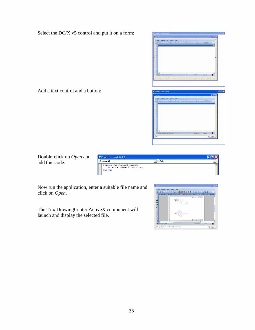
Select the DC/X v5 control and put it on a form:
Add a text control and a button:
Double-click on Open and add this code:
Now run the application, enter a suitable file name and click on Open.
The Trix DrawingCenter ActiveX component will launch and display the selected file.
35

Index ActiveX
component, 26 Visual Basic, example, 33
Annotation. See Markup Aperture, setting, 18 Application Preferences, 23 Area
Measuring, 14 summing multiple, 17
Background, dark, 24 Black/white display, 24 Browser version, 26 Browsing folders, 8 CALS files
headers, 23 rotate, 24
CD-ROM, files from, 8 Command Line control. See DDE Commands Conversion
raster to raster, 21 raster to vector, TracTrix, 21
Copying images, 10
Customizing Toolbars, 25 DDE Commands, 25 Default Unit, 23 Draw. See Markup dw5 files, 18 DWG/DXF
displaying fonts, 23 views, 23 x-refs, 23
email, PDF image of drawing, 12 Erasing, 20 Files
association/extensions, 27 more than one open, 9 Properties, 25 view same file, multiple places, 10
Font files directory, 24 Functions, table listing, 4 Heading, on print out, 11 Hiding
image, 10 HPGL
variants, 31
Inch to mm conversion table, 32 Insert corner, 19 Inversion, 23 Layers, 21
in DWG/DXF, 22 markup, 21
Length measuring tool, 14
Local Zoom, 16 Main window
footer contents, 7 Margin, 11 Markup, 18
.dw5 files, 18 Automatic, 16 directory, 24 editing, 19 hiding, when printing, 12 properties, 19 saving and sharing, 20 show at file open, 24 use of, 18
Measurements, 14 Mirroring, 23 missing
font /SHX files, 24 X-ref file, 24
mouse wheel zoom, 9 Move Side, 19 Multipage Files, 9 Panning, 9 PDF
creating, 12 Pen file
set up, 25 Plotbase, Ricoh, 24 Polygon
markup tool, 15 measuring tool, 15
Preview printing, 12 Printing, 10 Printing, fast setting, 24 Raster
converting formats, 21 difference between raster and vector, 2 formats supported, 28 Snap, 17
Rectangle
36

markup tool, 15 measuring tool, 15
Redlining. See Markup Rotation, 23
markup, 19 Scale
cross checking, 14 setting, 13 when printing, 11
Scanning, 9 Select Area Tool, 5 Slide show, 8 Snap, 17 Starting the application, 8 Vector formats supported, 31 Viewing, 9 Zooming, 9
37