triton display installation manual
TRANSCRIPT
ENGLISH
Triton DisplayInstallation Manual
bandg.com


| 1Preface | B&G Triton Display Installation Manual
DRAFT COPY
Preface
As Navico are continuously improving this product, we retain the right to make changes to the product at any time which may not be reflected in this version of the manual. Please contact your nearest distributor if you require any further assistance.
It is the owner’s sole responsibility to install and use the instrument and transducers in a manner that will not cause accidents, personal injury or property damage. The user of this product is solely responsible for observing safe boating practices.
NAVICO HOLDING AS AND ITS SUBSIDIARIES, BRANCHES AND AFFILIATES DISCLAIM ALL LIABILITY FOR ANY USE OF THIS PRODUCT IN A WAY THAT MAY CAUSE ACCIDENTS, DAMAGE OR THAT MAY VIOLATE THE LAW.
Governing Language: This statement, any instruction manuals, user guides and other information relating to the product (Documentation) may be translated to, or has been translated from, another language (Translation). In the event of any conflict between any Translation of the Documentation, the English language version of the Documentation will be the official version of the Documentation.
This manual represents the product as at the time of printing. Navico Holding AS and its subsidiaries, branches and affiliates reserve the right to make changes to specifications without notice.
CopyrightCopyright © 2012 Navico Holding AS.
WarrantyThe warranty card is supplied as a separate document. In case of any queries, refer to the brand web site of your display or system: www.bandg.com
Important text that requires special attention from the reader is emphasized as follows:
¼ Note: Used to draw the reader’s attention to a comment or some important information.
Warning: Used when it is necessary to warn personnel that they should proceed carefully to prevent risk of injury and/or damage to equipment/personnel.

2 | Preface | B&G Triton Display Installation Manual
Declarations and conformanceThis equipment is intended for use in international waters as coastal sea area administered by countries of the E.U. and E.E.A.
B&G Triton Display complies with the following regulations:
• CEunderEMCdirective2004/108/EC
• level2devicesoftheRadiocommunications(ElectromagneticCompatibility)standard2008
B&G Triton Display meets the technical standards in accordance with Part 15.103 of the FCC rules.
About this manualThis manual is a reference guide for installing the B&G Triton system. The manual assumes that the installer has at very least, basic knowledge of DC electrical systems, and of working with power tools with materials such as fiberglass and wood.
An understanding of basic navigation, nautical terminology and practices may be helpful in correct configuration of the product.
Warning: It is your sole responsibility to install and use the instrument and transducer(s) in a manner that will not cause accidents, personal injury or property damage. Always observe safe boating practices.
¼ Note: The choice, location, and installation of transducers and other components of the system are critical to the performance of the system as intended. If in doubt, consult your B&G dealer.
¼ Note: Global Positioning System: The Global Positioning System (GPS) is operated by the US Government which is solely responsible for its operation, accuracy and maintenance. The GPS is subject to changes which could affect the accuracy and performance of all GPS equipment anywhere in the world, including this instrument.

| 3Preface | B&G Triton Display Installation Manual
DRAFT COPY
The softwareThis manual is written for B&G Triton Release to Market 1 (RTM1). Please check web site for details on the current release version.
¼ Note: The menu route shown above is an example only and may not match the software installed on your unit!
¼ Note: To update the software you will need a compatible multifunction display / chartplotter running on the network. eg. B&G Zeus multi function display (MFD). If you do not have a suitable device on the network you can arrange to update the software via a B&G dealer.
You can download the latest version of the software from www.bandg.com and upgrade the displays via the B&G MFD, instructions on how to do this can be found on the B&G website. www.bandg.com
¼ Note: The manual may have been updated to match new software releases. The latest available manual version can be downloaded from www.bandg.com
¼ Note: Portions of this software are copyright © 2011 The FreeType Project (www.freetype.org). All rights reserved.


| 5Contents | B&G Triton Display Installation Manual
DRAFT COPY
Contents
1 Preface
7 Introduction
8 Overview9 Menus10 Check the contents
12 Installation12 Choosing a location12 Viewing angles13 Fitting with mounting clip14 Fittingwithretentionbracket14 Multipledisplays
15 Wiring15 Introduction to NMEA 2000 (SimNet)17 Daisy chaining the Triton display18 DropcableconnectionoftheTritondisplay19 Typical network example
20 Display20 Setup wizard27 Sources
30 Calibration30 Depth31 Sea temperature31 Boat speed35 Apparent wind35 Compass heading36 Damping

6 | Contents | B&G Triton Display Installation Manual
38 Autopilot39 Autopilot Setup39 Dockside44 Seatrial46 Pilotresponse47 Windresponse48 Seastatefilter48 Sailing50 Automatic steering
57 Troubleshooting
58 Technical Specifications58 Display59 Dimensional drawing60 Spares & Accessories

| 7Introduction | B&G Triton Display Installation Manual
DRAFT COPY
Introduction
TheTritonDisplayutilizesauniquebonded4.1-inchsunlightviewable LCD display to offer clearly read sailing information, including wind, speed, depth, heading, pilot status, log, timer and much more.
High contrast and a 155˚ viewing angle provide excellent readability, whilst the bonded display ensures there is no chance of condensation occurring regardless of the conditions.
Powerconsumptionisextremelylowforthisclassofproduct-155mA at 13.5 V with backlight driven at full brightness.
DualMicro-Cconnectorsprovideforquickandeasydaisy-chainconnection-idealforretrofitornewbuild.Micro-Cistheindustrystandard cabling used for NMEA 2000 systems.

8 | Overview | B&G Triton Display Installation Manual
Overview
The Triton Display and Pilot Controller
1 5768
94
32
1. Display
2. Menu / Enter key
Used to enter the main menu, select sub menus and confirm selection.
¼ Note: Press and holding the Enter key for 3 seconds takes you directly to the display setup lighting level screen. If the lighting level is set below 5 it will automatically increase to 5. Use the up and down keys to set the desired level and press Enter to confirm.
3. Page key
Scrolls through the eight default display pages and navigates back a step in menus.
¼ Note: the eight default display pages including Pilot page can be customized to display the required data.
4. Directional keys
Scrolls up and down through selected menus / set values.
5. Pilot Controller
6. Mode key
Changes the Pilot mode.7. Off key
Disengages the autopilot.8. Course control keys
Changes target course / Activates Non Follow Up (NFU) mode when in Standby mode.
9. Auto key
Engages the autopilot.

| 9Overview | B&G Triton Display Installation Manual
DRAFT COPY
MenusUnder normal operation, the unit will power up displaying the most recently used data page. To enter the menu use the Menu/Enter key.
1
2
3
4
1. Current menu
2. Selection highlight
3. Indication for more content off page
4. Menu expands to further level of detail

10 | Overview | B&G Triton Display Installation Manual
Check the contents
Triton Instrument Display
Mounting Clip
Sun Cover
Fixing Screws
Additional Retention Bracket
Threaded rods, Washers, and Fasteners for Retention bracket
0.6m Interconnect Cable (Micro-C)-Straightconnectors

| 11Overview | B&G Triton Display Installation Manual
DRAFT COPY
Installation Manual
Quick Reference Guide
Operation Manual DVDInstallation Manual& Operation Guide
Mounting Template
Triton Display
IMPORTANT. Do not use this template if it has been rescaled by copying or printing. If this is not the original, or is a print from a file, please check the dimension lines below are to scale before use.
IMPORTANT. Ne pas utiliser ce gabarit s’il a été photocopié ou imprimé en format réduit ou agrandi. Si ce gabarit n’est ni un original ni une version imprimée d’un fi chier PDF, veuillez vérifi er qu’il est à l’échelle avant de l’utiliser.
IMPORTANTE. no usar la plantilla si hay peligro que la escala original exacta se ha alterado por copias o procesos de impresión imprecisos. Si esto no es el original, o un PDF, verifi car que las líneas abajo están a la escala antes de usar.
WICHTIG. Diesen Vordruck nicht verwenden, wenn er durch Kopieren oder Drucken im Maßstab verändert wurde. Sollte es nicht das Original oder ein PDF-Ausdruck sein, müssen untenstehende Zeilen vor erwendung an den richtigen Maßstab angepasst werden.
BELANGRIJK. Gebruik deze mal niet indien de schaal is veranderd doordat het is gecopieerd of gedrukt. Indien deze mal niet het origineel of een print van PDF is, controleer dan of de onderstaande lijnen de juiste schaal zijn voordat u ze gebruikt.
IMPORTANTE. Não utilize este gabarito se a escala do mesmo tiver sido alterada por cópia ou impressão. Se não for o original ou uma cópia impressa de um arquivo PDF, verifi que as linhas abaixo, para acertar a escala antes da utilização.
VIKTIGT. Använd inte denna mall om den skalats om genom utskrift eller kopiering. Om detta inte är originalet eller en utskrift från en PDF, kontrollera att linjerna nedan stämmer med skalan innan det används.
IMPORTANTE. Non utilizzare questo modello se è stato ridimensionato copiandolo o stampandolo. Se questo non è l’originale o la stampa di un fi le PDF, verifi care se le linee che seguono devono essere dimensionate prima di essere utilizzate.
TÄRKEÄÄ. Älä käytä tätä kaaviota, jos sen mittakaava on muuttunut kopio-idessa tai tulostaessa. Jos tämä ei ole alkuperäinen tai PDF tuloste tarkista rajat mittakaavasta alla ennen käyttöä.
注意:请尽量不要使用本安装挖孔尺寸模版图的复印件。如果使用复印件,则在使用之前请确认其比例一定要与原件大小必须一致。
중요: 복사나 출력으로 크기가 조정 된 경우 이 템플릿을 사용하지 마십시오. 원본이 아니거나 인쇄물이면, 사용하기 전 아래 치수선의 눈금을 확인 해 주십시오.
注:このテンプレートは印刷やコピーによって縮尺が変わっていることがありますので使用しないで下さい。テンプレートがオリジナルのものでない場合には、下の寸法線を使って縮尺を確認してください。
*988-10136-001*
Check dimensions before cutting6"
150 mm
123 mm (4.84")118 mm (4.64")98.0 mm (3.86")89.0mm (3.5")
120m
m (4
.72"
)11
5 m
m (4
.53"
)
80.0 mm (3.15")
LC
LC
Suncover
Product outline
Product removal position
Remove shaded area
OR DRILL PILOT HOLE TO SUIT SELF TAPPING #8 SCREW
5 mm (0.20”)
3.5 mm 0.14 ”required for removing when flush mounted
Warranty Booklet

12 | Installation | B&G Triton Display Installation Manual
Installation
The Triton display may be mounted via a flush mounting clip or with the retention bracket attached to the rear of the unit.
Choosing a locationChoose the mounting locations carefully before you drill or cut. The display should be mounted so that the operator can easily use the controls and clearly see the display screen. Be sure the chosen location allows access for routing the cables.
Ensure that any holes cut will not weaken the boat’s structure. If in doubt, consult a qualified boat builder. Before cutting a hole in a surface, make sure that there are no hidden electrical wires or other parts behind the panel. Leave sufficient clearance space to connect all relevant cables.
If multiple instruments are to be mounted in a row, ensure measurement of space takes in to account the correct spacing between displays.
B&Gdisplaysarehigh-contrast,anti-reflectiveandareeasilyreadindirect sunlight.
For width, height and depth requirements, please see the drawings at the back of this manual.
Viewing anglesThe Triton display offers 170 degrees viewing angle, both horizontally and vertically. Avoid installation in locations that require the instrument to have significant rotation of axis relative to the deck. Users wearing polarized sun glasses may have trouble clearly reading a screen that is at a significantly different angle to the lenses.

| 13Installation | B&G Triton Display Installation Manual
DRAFT COPY
Fitting with mounting clip
Use the template to cut the required size hole in the chosen location. At the same time mark the holes to be drilled for the fasteners. Take care to be as accurate as possible when cutting out themountinghole-themountingclipshouldbeaclose,butnottight fit in the hole. If the clip requires pressure to get in to position, there is a high chance it will distort, and not retain the display as well as intended.
Check that the clip lines up with the markings for the fastener mounting holes, then drill the holes. Fasten the mounting clip in place with the supplied screws.
The display can then be fitted by pressing into the mounting clipaperture-apositive‘click’shouldbefeltwhenthedisplayengages with the clip. Check that all four edges of the display make good contact with the mounting surface, and apply adequate compression to the gasket.

14 | Installation | B&G Triton Display Installation Manual
Fitting with retention bracketThe Triton display may be mounted using only the mounting clip, or may be secured additionally with the retention bracket. In order to secure the bracket, adequate rear access must be available to fit the fasteners.
Before fitting the display in to the mounting position, firmly wind the threaded rods into the back of the Triton display by hand.
Place the display in to position and fit the retention bracket, followed by washers and fasteners.
Multiple displaysIf mounting Triton displays in a row or column, ensure that enough space is left for the sun covers to clip on.
Even where the sun covers are not required, the correct spacing should be used, as the displays require 3.5mm on each side when rotating for removal from the mounting clip.
The absolute minimum space that should be allowed for each display is:
• Width:123mm(4.84”)
• Height:120mm(4.72”)

| 15Wiring | B&G Triton Display Installation Manual
DRAFT COPY
Wiring
The B&G Triton Display can be connected to either an NMEA2000 or SimNet network. There is no separate power cable, as the unit is powered from the network.
TherearetwoMicro-Cconnectorsoneachdisplay,allowingfordaisy chaining, which greatly increases the ease of connecting multiple displays that are in close proximity, and can save in cable weight and loom size. Note this method is approved in SimNet networks, but not in NMEA 2000 networks.
Introduction to NMEA 2000 (SimNet)NMEA 2000 is a combined electrical and data specification, andisbasedonCAN(ControllerAreaNetwork-SAEJ1939)bustechnology. NMEA2000 permits exchange of data and commands between the interfaced products. NMEA2000 stipulates the use of Micro-CandMini-Chardwareforthephysicalaspectofthenetwork.
SimNet is largely based on NMEA2000, but with added proprietary messages, and it’s own physical cable and connector system. The data transfer capacity of NMEA 2000 is 50 times higher than that of theNMEA0183standardat4800baud.
Most NMEA2000 devices can be connected directly to a SimNet backbone and SimNet devices can be connected to an NMEA 2000 network by using adapter cables. The physical layout and limitations of the two networks are nearly identical, so the following information is interchangeable.
Essential network information • NMEA2000isapowerednetwork.Itmusthaveaseparate12-15V
DC power supply protected by a 5 Amp fuse. Do not connect the NMEA 2000 power cable to the same terminals as the start batteries, Autopilot Computer, Radar, thruster or other high current products
• AnNMEA2000networkconsistsofalinear“backbone”fromwhich“dropcables”connecttoNMEA2000devices
• A single drop cable has a maximum length of 6 m (20 ft). The total lengthofalldropcablescombinedshouldnotexceed78m(256ft)
• An NMEA 2000 networkhasamaximumcablelengthof100m(328ft), between any two points

16 | Wiring | B&G Triton Display Installation Manual
• An NMEA 2000 network needs to have a terminator at each end of the backbone. A terminator can be one of the following:
• a power cable with built in terminator
• a terminated blanking plug
• a wind transducer (terminator is in the mast head unit as opposed to mast cable).
• CertainSimradproductshavetwoMicro-CorSimNetconnectors,which can be made to be an in line component of the backbone. Connectingfromdevicetodeviceisknownas‘daisychaining’Thisnetwork topology is not officially NMEA 2000 compliant.
• NMEA2000 devices can be connected to the SimNet Network providing they:
• are NMEA2000 certified, or state full compatibility
• meet the CE, FCC regulations with a SimNet adapter cable
• donotexceedtheSimNetloadspecification-seeSimrad SimNet Installation Manual (20222006)
Planning and installing a network backbonePlan the backbone carefully.
The NMEA 2000 backbone needs to run between the locations of all products you want to install, typically in a bow to stern layout, and be no further than 6 m from a device to be connected.
Choose from the following components to make up your NMEA 2000 backbone:
• Micro-Ccables:Availablelengthsfrom0.4m(1.3ft)to25m(82.5ft)
• Micro-Cpowercableswithorwithouttermination
• T-connector.Useatlocationswhereyouwanttoconnectadeviceby drop cable
• Wind transducer. If using a wind sensor, plan to connect this to one end of the backbone as this has a terminator built in
• Micro-CmaleandMicro-CfemaletoSimNetadaptorcablesforconnecting to existing SimNet bus, or adding devices fitted with a SimNetconnectortoaMicro-Cnetwork.

| 17Wiring | B&G Triton Display Installation Manual
DRAFT COPY
Power the networkAn NMEA 2000 network requires its own 12 V DC power supply protected by a 5 amp fuse or breaker.
In smaller NMEA 2000 systems, the power connection may be made anywhere in the system,
For larger systems introduce power at a central point in the backboneto“balance”thevoltagedropofthenetwork.Useapowercable without termination.
¼ Note: When joining an NMEA 2000 network to a SimNet network, it is not necessary to introduce power to both.
¼ Note: Do not connect the power cable to the same terminals as the autopilot computer, pulse radar, bow thruster or other high current devices-thenetworkmaybeaffectedbyvoltagedropwhenthesedevices are operated. Avoid connection to the engine starting batteries where possible.
Daisy chaining the Triton displayWhere displays are located close together, the supplied right angle Micro-Ccablemaybeusedtolinkthedisplaysinseries.Thedaisychain should form part of the back bone. It is not advisable to daisy chain devices off a drop cable.
LTWLTW
2
LTWLTW
2
1
3
1 1
3
1. Triton Display
2. RightangleMicro-Cplugconnectorcable0.4m(supplied)
3. NMEA2000 / SimNet backbone

18 | Wiring | B&G Triton Display Installation Manual
Drop cable connection of the Triton display
2
2
3 4
4
4
1
2
3
1
1
1. Triton Display
2. Drop cable
3. NMEA2000 / SimNet backbone
4. Micro-CT-connectors

| 19Wiring | B&G Triton Display Installation Manual
DRAFT COPY
Typical network example
ECHO
RADAR
CHART
NAV
INFO
PAGES
MENUPLOT
GO TO
MARK
VESS
EL
WIN
IN MOB
ABC
DEF
12
3
JKL
GHI
MNO
45
6
TUV
PQRS
WXYZ
7 STBY
AUTO
PWR
8 0
9OUT
ECHO
RADAR
CHART
NAV
INFO
PAGES
MENUPLOT
GO TO
MARK
VESS
EL
WIN
IN MOB
ABC
DEF
12
3
JKL
GHI
MNO
45
6
TUV
PQRS
WXYZ
7 STBY
AUTO
PWR
8 0
9OUT
120
LTW
LTW
LTW
LTW
Rx
TxBIIT
PWR

20 | Display | B&G Triton Display Installation Manual
Display
This section focuses on initial setup of settings that should require infrequent adjustment. For regularly used features, refer to the Operation or Quick Guide.
Setup wizardThe first time a new Triton display is turned on, the Setup Wizard will guide you through essential configuration items.
• Language
• Boat Type
• Set Date and Time Format
• Unit Selection
• Display Mode
The available settings and descriptions are given in the following section on the Setup Menu.
Setup
Setup MenuUnder normal operation, the unit will power up displaying the most recently used data page. To enter the menu use the selection key.
Select Setup for further options detailed in this section.

| 21Display | B&G Triton Display Installation Manual
DRAFT COPY
System setupIn display setup you can set the lighting zone, enter night mode and change the lighting level.
¼ Note: Pressandholdthe‘Enter’keyfor3secondswilltakeyoudirectly to the display setup lighting level screen. If the lighting level is set below 5 it will automatically increase to 5. Use the up and downkeystosetthedesiredlevelandpress‘Enter’toconfirm.
Lighting zoneAll units in the selected lighting zone will mirror each other’s light settings. Default setting is Network.
Night modeChange the display to night mode colour pallet. All displays in the selected lighting zone will also change to night mode.
Lighting levelAdjustthebacklightlevelfrom1-10.
Time & DateFrom the time and date menu you can set your preferred time / date format and local time offset. Once complete select Save to save your settings and exit.
¼ Note: Local time is calculated based on UTC provided via a GPS unit connected to the network.

22 | Display | B&G Triton Display Installation Manual
UnitsSet the preferred unit of measurement you want data to be displayed in.
Parameter Options Default value
Boat speed
kn Knots
knkph Kilometers per hour
mph Miles per hour
Wind speed
kn Knots
knm/s Meters per second
mph Miles per hour
Distance
nm Nautical miles
nmmi Miles
km Kilometers
Depth
ft Feet
mm Meters
fa Fathoms
HeadingºM Magnetic
ºMºT True
TemperatureºF Fahrenheit
ºCºC Centigrade
Pressure
Hg Inches of Mercury
mbmb Millibars
hPa Hectopascal
¼ Note: If magnetic variation is not available via a GPS an offset can be entered manually. See Magnetic variation for more information.The same applies if the user wants to read magnetic heading, but only receives true heading from the compass.
| 23Display | B&G Triton Display Installation Manual
DRAFT COPY
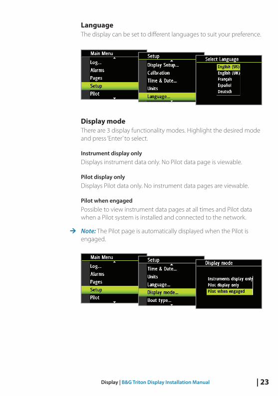
LanguageThe display can be set to different languages to suit your preference.
Display modeThere are 3 display functionality modes. Highlight the desired mode andpress‘Enter’toselect.
Instrument display onlyDisplays instrument data only. No Pilot data page is viewable.
Pilot display onlyDisplays Pilot data only. No instrument data pages are viewable.
Pilot when engagedPossible to view instrument data pages at all times and Pilot data when a Pilot system is installed and connected to the network.
¼ Note: The Pilot page is automatically displayed when the Pilot is engaged.

24 | Display | B&G Triton Display Installation Manual
Boat typeAllows selection between Power Boat or Sail Boat. Boat type changes the icon on the depth plot page, as well as determining available features and operational modes for the autopilot.
Software informationShows the software version currently installed on the display. Press ‘Enter’orthe‘Page’keytonavigatebacktothemenu.
DiagnosticsShows an overview of the data being transmitted on the network, The list shows the network bus status, bus load as a percentage as well as quantity and type of data messages.
¼ Note: We recommend that you use this diagnostic tool as a basic overview of the network status. For more detailed information it is suggested that you check the individual source information via the device list.

| 25Display | B&G Triton Display Installation Manual
DRAFT COPY
SystemFrom the system menu there are several options to reset the system, place the display into simulator and get the current software information.
Reset optionsThere are a variety of reset options available from the system menu.
¼ Note: Whenever a reset option is selected there will be a dialog box asking you to confirm that you wish to reset before any further action is taken. If you wish to cancel the reset, selecting No will return you to the system menu.
Network resetResets the source selection on all displays connected to the network.
Autopilot resetResets the Pilot and returns all settings to factory defaults.
Warning: The Pilot will need to be commissioned before it is fit for purpose. Do not engage the autopilot until it has been commissioned and a sea trial has been completed.

26 | Display | B&G Triton Display Installation Manual
Reset to FactoryResets the current display to the default settings. When the unit is restarted you will see the original startup wizard asking you to set the display.
Warning: All settings for instrument and Pilot will be restored to factory default. The Pilot will need to be commissioned before use.
SimulatorSimulator mode sends simulated data to the display.
Warning: It is not advisable to enter simulator mode when using your instrument system as a navigation aid.

| 27Display | B&G Triton Display Installation Manual
DRAFT COPY
SourcesA data source can be a sensor or a device connected to the NMEA2000 network, providing information and commands to other networked devices. The data sources are normally configured at first time turn on.
It should only be necessary to update this data if a new source is added, source is missing (sensor failure), source has been enabled/disabled, sensor replaced or a network reset.
Auto selectThe Auto select option will look for all sources connected to the instrument system. If more than one source is available for each item, the display will automatically select from the internal device priority list.
1. Verify that all interfaced units are powered on
2. Pressthe‘Enter’keytostarttheautoselectprocedure

28 | Display | B&G Triton Display Installation Manual
The operator will be noted when the auto select process is completed.
¼ Note: If more than one source is available on the network you can chose your preferred source from the sources menu. See “Manual sourceselection”formoreinformation.
Manual source selectionIf more than one source is available for an item, the preferred source may be selected manually. As an example, the following illustrations show how the compass source is changed.
Select the preferred data source. The selected source will be indicated by a tick in the check box.
Device listShows a list of devices connected to the Network.

| 29Display | B&G Triton Display Installation Manual
DRAFT COPY
Selecting a device from the list will show you an information pane with details of that device.
SomedevicessuchasanRC42compassstoretheirconfiguration,calibration and offset data in their own memory and not in the display memory. For devices of this type you can check the data information, configure and calibrate the device by selecting Options.
DataThe data list shows the data type that the device is transmitting.
Configure
InstanceEnter a number to differentiate between instances of the same device.
OffsetCertain devices will let you enter an offset value to compensate for the position of the sensor or variation of sensor data.
¼ Note: Some devices can be configured further. If a device transmits other data it may be shown on this page also.
CalibrateFor compass sensors only, once installed you will need to calibrate the device. Select Calibrate and follow the instructions on the display. See calibration section of the manual for more information.
30 | Calibration | B&G Triton Display Installation Manual
Calibration
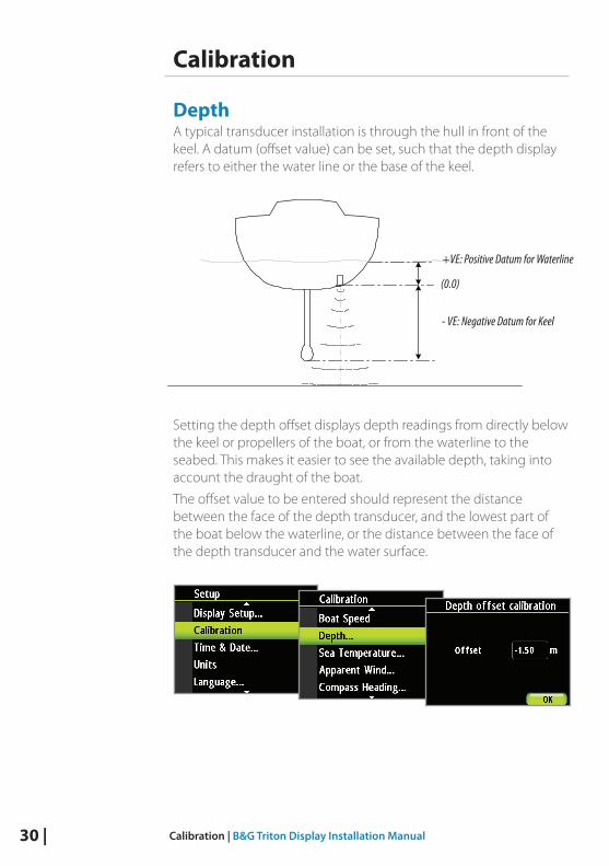
DepthA typical transducer installation is through the hull in front of the keel. A datum (offset value) can be set, such that the depth display refers to either the water line or the base of the keel.
+VE: Positive Datum for Waterline
- VE: Negative Datum for Keel
(0.0)
Setting the depth offset displays depth readings from directly below the keel or propellers of the boat, or from the waterline to the seabed. This makes it easier to see the available depth, taking into account the draught of the boat.
The offset value to be entered should represent the distance between the face of the depth transducer, and the lowest part of the boat below the waterline, or the distance between the face of the depth transducer and the water surface.

| 31Calibration | B&G Triton Display Installation Manual
DRAFT COPY
Sea temperatureIf a suitable temperature sensor is fitted, the system will monitor the sea temperature.
The offset value to be entered should adjust the temperature reading from the sensor to match a calibrated thermometer when submersed in the water
Boat speedSpeed calibration is necessary to compensate for hull shape and paddlewheel location on your boat. For accurate speed and log readings, it is essential that the paddlewheel is calibrated. Boat speed values can be shown in knots, kph or mph. Your preferred unit of measurement can be set in the units page of the setup menu.
Auto - Calibration via reference to GPS SOG valueThis is an AutoCal facility that uses speed over ground (SOG) from your GPS and compares the average of SOG against the average boat speed from the speed sensor for the duration of the calibration run.
¼ Note: This calibration should be made in calm sea with no effect from wind or tidal current.

32 | Calibration | B&G Triton Display Installation Manual
1. Bring the boat up to cruising speed (above 5 knots)
2. Select Auto on the Boat speed calibration page
3. When the calibration is completed the Boat speed calibration scale will show the adjusted percentage value of the boat speed.
USE SOG as boat speedIf boat speed is not available from a paddle wheel sensor it is possible to use speed over ground from a GPS. SOG will be displayed as boat speed and used in the true wind calculations and the speed log.
Manual adjustment of boat speedAdjust the boat speed manually by selecting the Boat speed percentage slider. Adjust the percentage up or down as desired. Confirm the value. Select OK once complete.

| 33Calibration | B&G Triton Display Installation Manual
DRAFT COPY
Distance referenceThis facility enables the user to calibrate the log accurately and simply. Calculations are performed by the display that works out the boat speed over a known distance.
To calibrate the boat speed via a distance reference you will need to complete consecutive runs, under power at a constant speed made along a given course and distance.
¼ Note: To eliminate the effect of tidal conditions it is advisable to perform at least two runs, preferably three, along the measured course.
How To Calibrate via Distance ReferenceEnter the desired distance in nautical miles that you would like to calculate the distance reference over.
When the boat gets to the predetermined starting position of the distance reference calculation start the calibration timer.

34 | Calibration | B&G Triton Display Installation Manual
Distance reference diagramReferring to the diagram reference diagram, A and B are the markers for each run and X is the actual distance for each run as ascertained from a suitable chart or GPS for example.
A BX
Start Run 1 Stop Run 1
Stop Run 1
End Calibration
Start Run 2
Start Run 3
As the boat passes marks A and B on each run, instruct the system to start (Start Run) and stop (Stop Run) and finally OK to end calibration (End Cal Runs).
After the last run is completed and OK has been selected, a pop up warning will ask you if you wish to replace the current calibration with the new one. Select Yes to complete.

| 35Calibration | B&G Triton Display Installation Manual
DRAFT COPY
Apparent windThis provides an offset calibration in degrees to compensate for any mechanical misalignment between the masthead unit and the center line of the vessel.
To check the masthead unit alignment error we recommend you use the following method which involves a sailing trial.
Sail on a starboard tack on a close hauled course and record the wind angle, then repeat the process on a port tack. Divide the difference between the two recorded numbers and enter this as the wind angle offset.
33º 27º
WINDStarboard Tack Port Tack
Starboard tack = 33º
Port tack = 27º
Difference:33º-27º=6º
Offset:6º/2=-3º
If the starboard apparent wind angle is greater than the port angle then divide the difference by 2 and enter this as a negative offset. If the port angle is greater than the starboard then divide the difference by 2 and enter this as a positive offset.

36 | Calibration | B&G Triton Display Installation Manual
Compass headingThe compass offset compensates for fixed errors (misalignment) between the compass sensor and the direction of the boat.
To accurately enter a compass offset, the boat’s heading must be referenced to, for example: a calibrated bowl compass.
The offset value will be the difference between the known source and the currently displayed heading.
Enter this value as the offset in the compass heading field as a plus orminusintegerupto180º
USE COG as headingIf heading data is not available from a compass sensor it is possible to use course over ground from a GPS. COG will be displayed as heading and used in the calculation of true wind direction.
¼ Note: The autopilot cannot be operated using COG as the heading source. COG cannot be calculated when stationary.
DampingThe damping rate effects the frequency that the sensor data is updated on the display, the greater the damping value the smoother the number change will be but the slower the response will be to data change.

| 37Calibration | B&G Triton Display Installation Manual
DRAFT COPY
Decimal placesIt is possible to change how many decimal places speed and sea temperature data will be displayed with.
Choose how many decimal places you wish to have shown for that specific data type.
Magnetic variationAdjust how the system handles magnetic variation.
Auto: Automatically calculates variation based on position and date.
Manual: If variation is not available enter a value manually.
Sounds:Turn the keypress and alarm sounds on or off.
¼ Note: Silencing the alarm sound does not deactivate the alarms. When an alarm is activated the warning notification will be shown on the display regardless of the sound being on or off.

38 | Autopilot | B&G Triton Display Installation Manual
Autopilot
IfanAC12orAC42 autopilot computer is connected to a Triton display and AP controller, autopilot control and setup functionality will be made available.
Warning: The installation settings must be performed as part of the commissioning of the Pilot system. Failure to do so correctly may prohibit the Pilot from functioning properly! The Installation menu can only be accessed in Standby mode.
¼ Note: Some important points regarding the installation settings:When the Pilot is delivered from factory and ANY TIME AFTER AN AUTOPILOT RESET HAS BEEN PERFORMED, the installation settings are all reset to factory preset (default) values. The automatic interface prompt will appear and a complete setup has to be made.
The Sea trial settings are dependent on successful completion of the Dockside settings.
¼ Note: If you select the Pilot page and the Pilot has not been commissioned you can go straight to the commissioning page by selecting Setup.

| 39Autopilot | B&G Triton Display Installation Manual
DRAFT COPY
Autopilot SetupBefore the Pilot can be used you must first commission it and complete all of the dockside procedures before it is operational.
DocksideThe dockside procedures are initiated from the commissioning dialog. Completed procedures are labelled with a tick.
The following menu items are accessible and can be set up in the Installation menu:
• Boat type
• Rudder feedback
• Drive voltage
• Drive engage
• Rudder test
• Depth calibration
• Minimum wind angle
• Nav change limit

40 | Autopilot | B&G Triton Display Installation Manual
Boat TypeType of boat selected will affect the steering parameters, and the functions available in the autopilot system. The options are: Planing, Displacement, Sail and Outboard.
¼ Note: Wind mode is only available if boat type is set to sail.
Drive voltage (V)Setsthedrivevoltagetypeto12or24V
Rudder Feedback CalibrationMake sure the unit is installed and aligned as per instruction in the AC12/42Installationmanual.Therudderfeedbackcalibrationwillset the correct relationship between the physical rudder movement and the rudder angle readout.
Max starboard• Manually move the helm to starboard until the rudder stops at
starboard lock hard over.
• The Max starboard angle is the angle read by the rudder feedback unit before any adjustment is made.
• If the actual rudder angle is different from the angle displayed, correct the reading with the Up/Down keys.
• Confirm Rudder feedback calibration to starboard by selecting Next.
Max port• Manually move the helm to port until the rudder stops at port lock
hard over.
• Adjust the displayed angle the same way as for starboard rudder.
• Confirm Rudder feedback calibration to port by selecting Next.

| 41Autopilot | B&G Triton Display Installation Manual
DRAFT COPY
¼ Note: Manyboatshave±45°(90°H.O.-H.O.)rudderangleasstandard. So if you are not going to make any adjustment to the displayed angle you should still highlight the reading and confi rm. This is necessary to prevent the rudder from hitting the end stops.
Set Rudder to 0 (zero) Bring the rudder to midship position and confi rm. This will adjust an incorrect reading caused by misalignment of the rudder feedback unit.
Rudder Test
¼ Note: If the boat uses power assisted steering, it is important that the engine or electric motor used to enable the power assist steering be turned on prior to this test.
Warning: Stand CLEAR of the wheel and do not attempt to take manual control of the wheel during this test!
Bring the rudder manually to midship position before starting the test.
After a few seconds the autopilot Computer will issue a series of PORT and Starboard rudder commands and automatically verify correct rudder direction.
It detects minimum power to drive the rudder and reduces the rudderspeedifitexceedsthemaximumpreferredspeed(8°/sec.)forautopilot operation.
The Rudder test is verifi ed by the display showing Completed Rev. motor, Completed Solenoids, or Failed. If Failed is given, check for correct electrical connection.
Alsoreferto”Alarms”

42 | Autopilot | B&G Triton Display Installation Manual
Rudder drive Ensure that the rudder information is set correctly before you continue with the Dockside commissioning.
Drive voltage (V)Setsthedrivevoltagetothetypeinstalledonthevessel12or24V
Drive engageDrive engage has the following settings: Auto and Clutch.
Clutch:This is the default setting and it allows you to steer the boat from the helm when in Standby mode. A clutch will be engaged on the drive unit locking out the steering when Auto is selected.
Auto:This setting is implemented for future use. Always use the Clutch (default) setting.
Motor outputThe Motor output (displayed as a percentage) is the amount of available power needed to achieve correct rudder speed on automatic steering (Maximum speed is used in NFU mode). This setting will allow you to adjust the rudder speed to be different from the one automatically set in the rudder test.

| 43Autopilot | B&G Triton Display Installation Manual
DRAFT COPY
Rudder deadbandThe rudder deadband function is adaptive and is continuously updating. It prevents the rudder from hunting and the adaptive function optimizes the deadband to the speed of the boat and the load on the rudder.
Iftheauto-settingdoesnotperformproperlyduetohighinertiafrom the wheel, it can be adjusted manually.
Find the lowest possible value that will prevent the rudder from continuous hunting. A wide deadband will cause inaccurate steering. It is recommended to check rudder stability in Auto mode when the boat is moving to get pressure on the rudder.

44 | Autopilot | B&G Triton Display Installation Manual
Sea trialAfter completing the Pilot calibration and all settings in the installation menu, you will need to perform a final sea trial.
¼ Note: The sea trial should be conducted in open waters at a safe distance from other traffic.
• •SteertheboatonallcardinalheadingsinAutomode
• •Startwithlowandmediumspeedstogetfamiliarwiththeresponsefrom the Pilot
• Verify the Hi/Lo transition and the effect of Lo and Hi parameter settings
• Check the effect of the Response adjust
• Set waypoints into each navigator connected to the system, and verify that the Pilot steers in Navigation mode for each Navigation source
• If the boat is a sailboat use the Wind mode and engage the Pilot at different wind angles.
• If the rudder response feels aggressive during the sea trial, you may want to reduce the rudder speed to get a smoother steering. On a sailboat you may want to have a higher rudder speed when running downwind.
• The motor Drive Out can be set with the above in mind. Never adjust in more than 10% steps with respect to the reading set during the automatic rudder test. Always perform a new Autotune after the adjustment.

| 45Autopilot | B&G Triton Display Installation Manual
DRAFT COPY
AutotuneAutotune is a feature that automatically sets the most important steering parameters (Rudder and Counter Rudder) by taking theboatthroughanumberofS-turns.Thescalingfactorsoftheparameters are also set automatically as a function of the boat type selection performed in the Dockside menu.
The automatic tuning process is also verifying/adjusting the Rudder zero alignment made in Dockside setup. Automatic tuning is a procedure that is not required for the Pilot to function as it is preset withsteeringparametersthatshouldsteermostboatsinthe30-50foot range.
Recommended speed during Automatic tuning should not exceed 10 knots. It should be performed in calm or moderate sea conditions. For displacement boats use a speed that is approximately half the normal cruising speed (i.e. if cruising speed is 10 knots, perform the Autotune at about 5 knots).
Select Autotune to begin the tuning process. Select yes to confirm Autotune.

46 | Autopilot | B&G Triton Display Installation Manual
After the Autotune has been completed the rudder must be controlled manually, as the autopilot has returned to Standby mode. The Automatic tuning function will take control of the boat and performanumberofS-turns.
¼ Note: Autotune must always be performed in open waters at a safe distance from other traffic. The Automatic tuning function may take from 2 to 3 minutes to complete. To stop the Autotune, press the ‘Enter’key.
After the Autotune process has been completed, a tick will appear next to the Autotune tab and there should be no need for further adjustments. Fine tuning of these parameters are made by the response control, however, viewing or changing the parameters can be made in Auto mode by entering Installation in the Main menu.
Pilot responseThe Autotune function is so refined that the majority of boats will need no further adjustments of the steering parameters. On some boats, however, in particular sea conditions a fine tuning of the steering parameters may improve the performance of the autopilot.
The Response control allows you to make this fine tuning for each of the two (Hi/Lo) parameter sets. The response can be set to ninelevels.Level4isdefaultwithparametervaluesassetbytheAutotune function. If no Autotune is made (not recommended) the level4valuesarethefactorydefaultvalues.
• A low response level reduces the rudder activity and provides a more loose steering.
• A high response level increases the rudder activity and provides a more tight steering.
• ResponseleveltoohighwillmaketheboatstartS-ing.
• When you access the RESPONSE page the highlighted Response parameter is the one that is active.
¼ Note: Adjustment of Hi and Lo values can be performed even with the boat out of the water.

| 47Autopilot | B&G Triton Display Installation Manual
DRAFT COPY
Selection of Hi / Lo parameters
The Manual select item has three alternatives:
Auto – Hi – Lo.• Auto is automatically set by speed input
• Hi or Lo must be set manually when there is no speed input
Thesub-headlineinthedisplayshowstheactiveparametersetandhow it is selected.
Wind response Verify that the difference between Set Heading and the actual heading is at an acceptable minimum.
If the difference between the set wind angle and the actual wind angle is too high, increase the Wind response to reduce the difference.
IftheactualwindangleisS-ingaroundthesetwindangle,ortherudder activity is too high, the Wind response should be reduced.
Range Change per step Default
1-9 1 4
48 | Autopilot | B&G Triton Display Installation Manual
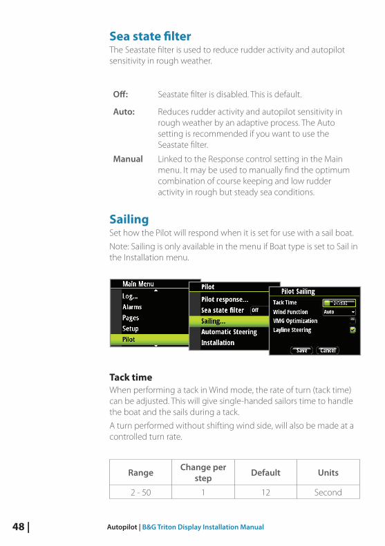
Sea state filterThe Seastate filter is used to reduce rudder activity and autopilot sensitivity in rough weather.
Off: Seastate filter is disabled. This is default.
Auto: Reduces rudder activity and autopilot sensitivity in rough weather by an adaptive process. The Auto setting is recommended if you want to use the Seastate filter.
Manual Linked to the Response control setting in the Main menu. It may be used to manually find the optimum combination of course keeping and low rudder activity in rough but steady sea conditions.
SailingSet how the Pilot will respond when it is set for use with a sail boat.
Note: Sailing is only available in the menu if Boat type is set to Sail in the Installation menu.
Tack timeWhen performing a tack in Wind mode, the rate of turn (tack time) canbeadjusted.Thiswillgivesingle-handedsailorstimetohandlethe boat and the sails during a tack.
A turn performed without shifting wind side, will also be made at a controlled turn rate.
Range Change per step Default Units
2-50 1 12 Second

| 49Autopilot | B&G Triton Display Installation Manual
DRAFT COPY
Tack angleIn Wind function Auto mode the set tack angle replaces a similar change of the set course using the starboard and port keys.
Range Change per step Default Units
50-150 1 100 º
Wind functionWith Wind function set to auto, the autopilot will automatically select between apparent and true wind steering. Auto is default and recommended for cruising. When the boat is running, it will also be surfing on the waves.
This may lead to significant changes in boat speed, hence changes in apparent wind angle. True wind steering is therefore used when running, while steering to apparent wind is used when beating or reaching.
When sailing in closed waters, the apparent wind angle may change temporarily due to gusts. It may then be preferred to sail to; select True.
Range Default
Auto-Apparent-True Auto
VMG optimizingOptimizing the VMG to wind will be active for 5–10 minutes after a new wind angle has been set and only when beating.
Range Default
On-Off On

50 | Autopilot | B&G Triton Display Installation Manual
Layline steeringLayline steering is useful when navigating. Cross Track Error (XTE) from the navigator will keep the boat on the rhumb line. If the XTE from the navigator exceeds 0.15 nm, the autopilot will calculate the layline and track towards the waypoint.
XTE will be displayed in the upper left corner above the mode index when layline steering is active
Range Default
Off-On Off

| 51Autopilot | B&G Triton Display Installation Manual
DRAFT COPY
Automatic steeringThe Automatic steering menu contains steering parameters for compass steering, wind steering and nav steering. These steering parameters can be changed if needed to improve sailing performance.
From this menu you can set the transition speed, high and low boat speed parameters to account for changes in boat speed, rudder angle, wind and compass settings.
Transition speedThe Transition speed is the speed at which the Pilot will automatically change the steering parameter set from Hi to Lo parameters, or vice versa.
¼ Note: The default setting of the Transition speed is 6 knots
HighHigh value parameters for automatic steering at low speed and when running with a sailboat.
LowLow value parameters for automatic steering at high speed and when sailing into the wind or reaching with a sailboat.

52 | Autopilot | B&G Triton Display Installation Manual
¼ Note: The two most important parameters that determine the performance of the automatic steering are Rudder Gain and Counter Rudder.
RudderSets the rudder gain which is the ratio between the commanded angle and the heading error.
Too little rudder
Set Course
Too much rudder
Set Course
• Too little Rudder and the autopilot fails to keep a steady course
• Too much Rudder gives unstable steering and reduces speed
• Low speed requires more rudder than high speed
¼ Note: Seealso“MinimumRudder”

| 53Autopilot | B&G Triton Display Installation Manual
DRAFT COPY
Counter rudderCounter Rudder is the parameter that counteracts the eff ect of the boat’s turn rate and inertia. For a short time period it is superimposed on the proportional rudder response caused by the heading error. It may sometimes appear as if it tends to make the rudder move to the wrong side (counter rudder).
The best way of checking the value of the Counter Rudder setting is when making turns. The fi gures illustrate the eff ects of various Counter Rudder settings.
Counter rudder setting too low = Overshoot response
New course
Counter rudder setting too high = Sluggish and creeping response
New course
Correct setting of counter rudder, ideal response
New course
AutotrimAutotrimstandardvalueis40secondswhichshouldworkwellonmost boats.
Rule of thumb: Set to same value (seconds) as the boat’s length in feet.
Rate limitShouldbekeptat6.0°/secondunlessthereisaneedformorerapidresponse in turns.

54 | Autopilot | B&G Triton Display Installation Manual
Minimum rudderSome boats may have a tendency to not respond to small rudder commands around a set course because of a small rudder, rudder deadbandorWhirls/disturbanceofthewater-streampassingtherudder. Turning the Minimum Rudder function on, may improve the course keeping performance on some boats, but will increase the rudder activity.
Range Change per step Default Units
Off-5 0.1 Off º
¼ Note: During the sea trial, only set Minimum Rudder to ON if it proves to give a better course keeping performance in calm sea. It should be set after the Autotune has been performed and a possible fine tune of the Rudder parameter.
Minimum wind angle Port / StarboardThe Minimum wind angle is the apparent wind angle that the boat sails to when close hauled. This parameter will vary from boat to boat.

| 55Autopilot | B&G Triton Display Installation Manual
DRAFT COPY
TheMinimumwindangleappliesforthetack-preventfunction.Italso applies when the autopilot is operating in WindNAV mode.
You can select different minimum wind angles for port and starboard. The difference between port and starboard will be taken into account when calculating the Distance To Turn (DTT).
Range Change per step Default Units
15-90 1 30 º
Navigation change limitIn Navigation mode, when the required course change to next waypoint in a route is more than the set limit, you are prompted to verify that the upcoming course change is acceptable. The limit is adjustable.
¼ Note: Nav change limit screen can also be reached from the Nav modemainscreenbypressingthe‘Menu’keyfollowedbythe‘Mode’keywithin2seconds.
Range Change per step
Default Units
10-30 10 10 º

56 | Autopilot | B&G Triton Display Installation Manual
Resetting the Pilot
Warning: all previous Pilot settings will be lost! Before engaging the Pilot the commissioning and calibration process must be completed.

| 57Troubleshooting | B&G Triton Display Installation Manual
DRAFT COPY
Troubleshooting
Issue Solution
Unit does not power up • Check that the NMEA2000/SimNet network has 12V connected.
• Try connecting to a different network cable in case power wires damaged internally.
Unit does not show data for a specific source
• In the advanced setup menu, select sources, and manually select the required data source.
• Check the network connection on the data source.
Unit does not show any data from any connected source
or
Unit data sources intermittently drop out.
• In the advanced setup menu, select sources option, then select AUTO SELECT.
• Check the Device List menu and see if any devices are detected.
• Try connecting to a different network cable in case data wires damaged internally.
• In the advanced setup menu, check the diagnostics page to see if any errors are occurring.
• Check network topology and termination rules are correctly implemented.
• Disconnect other devices fromnetwork,one-by-one,starting with 3rd party devices.

58 | Technical Specifications | B&G Triton Display Installation Manual
Technical Specifications
Display
Weight 0.28kg(0.6lbs)
Power consumption 150 mA at 13.5V
Network load Maximum 10 Triton displays
Colour Black
Size 4.1”(Diagonal)4:3Aspectratio
Type TransmissiveTFT-LCDWhiteLEDback-light
Resolution 320x240pixels
Illumination White (day mode) / Red (night mode)
Environmental Protection IPX7
Safe distance to compass 0.3 m (1.0 ft.)
Temperature
Operating 0 to +55 ºC (+32 to +130 ºF)
Storage -30to+70ºC(-22to+158ºF)

| 59Technical Specifications | B&G Triton Display Installation Manual
DRAFT COPY
Dimensional drawing
118 mm (4.64")
120m
m (4
.72"
)11
5 m
m (4
.53"
)
Suncover outline
123 mm (4.84")
18.9 mm (0.74")
LTW
40mm (1.57")
84 m
m (3
.31"
)
17 mm (0.67")
60 | Technical Specifications | B&G Triton Display Installation Manual
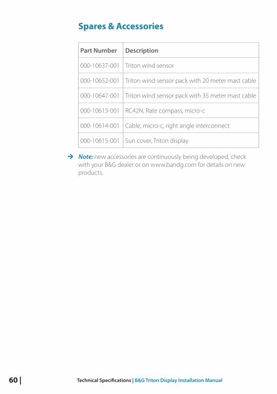
Spares & Accessories
Part Number Description
000-10637-001 Triton wind sensor
000-10652-001 Triton wind sensor pack with 20 meter mast cable
000-10647-001 Triton wind sensor pack with 35 meter mast cable
000-10613-001 RC42N,Ratecompass,micro-c
000-10614-001 Cable,micro-c,rightangleinterconnect
000-10615-001 Sun cover, Triton display
¼ Note: new accessories are continuously being developed, check with your B&G dealer or on www.bandg.com for details on new products.


*988
-102
22-0
01*
N2584