trisen 110 self-powered controller operations...
TRANSCRIPT
TRISEN 110 Self-Powered Controller
Operations Guide
Document No.: 4912-0003A
February 2007
Rev. 4
Webster, Texas

ii
Copyright Information in this document is subject to change without notice. Companies, names and data used in examples herein are fictitious unless otherwise noted. No part of this document may be reproduced or transmitted in any form or by any means, electronic or mechanical, for any purpose, without the express written permission of Invensys Triconex.
© 1991–2007 by Invensys Systems, Inc. All rights reserved.
Invensys Triconex reserves the right to make improvements in the design, construction, and appearance of its products without prior notice.
Printed in the United States of America.
February 2007 Rev. 4
iii
Revision History Rev. 0 September 1991 Initial Issue.
Rev. A November 1991 General technical revisions.
Rev. B December 1991 General technical revisions.
Rev. C January 1992 Technical changes to sections 5 and 6 only.
Rev. D January 1992 Technical changes to section 6; added min/max output paragraph.
Rev. E March 1993 Revised Figures 7-1, 7-2, 7-3, and 7-4 for CSA approval.
Rev. F July 1993 Revised the following pages:
i, iv, ix, x, xi, xiii, xiv, 1-1, 2-1, 2-5, 3-1, 3-7, 3-9, 3-10, 5-1, 5-2, 5-8, 5-9, 5-10, 6-7, 7-3, 7-4, 7-5, 7-6, 7-7, 7-13, 7-14, 7-15, 8-2, 8-3, and 8-4.
Drawing 91-1026 was revised and Drawing 92-2163 was added to Section 7.
Rev. 1 July 1998 General editorial revision including format for A4.
Rev. 2 June 1999 Changes to Figures 5, 6 and 15; and to last paragraph of Chapter 5.
Rev. 3 Oct 2003 Add calibration procedure for DT9. Update address/legal name. Update certifications.
Rev. 4 February 2007 Added the ControlAir I/P Transducer and made general technical revisions and corrections.
February 2007 Rev. 4
iv
Warnings! READ THIS ENTIRE MANUAL AND ALL RELATED PUBLICATIONS PERTAINING TO THE WORK TO BE PERFORMED BEFORE INSTALLING, OPERATING, OR SERVICING THIS EQUIPMENT.
• Practice all plant and safety codes and standards. Failure to follow instructions can result in personal injury and/or property damage.
• To prevent ignition of hazardous atmosphere, do not remove covers of Class I Division I (explosion-proof) units with power applied.
• All servicing should be performed by qualified technicians. Dangerous voltages may be present on the circuit boards.
• Use extreme caution when working around power-input cables. These cables may have potentially lethal voltages on them.
• Be very careful when working on the digital (or discrete) input/output field termination panels. The external devices being controlled can have high, potentially lethal voltages on them. Turn off the power to the external devices before disconnecting or connecting the cable or a wire between the digital (or discrete) input/output field termination panels and the field wiring.
• Replace fuses only with specified parts for continued safe operation.
• Equip the engine, turbine, or other type of prime mover with an overspeed (overtemperature or overpressure, where applicable) shutdown device that operates totally independently of the prime mover control device. This protects against run-away or damage to the engine, turbine, or other prime mover, or personal injury or loss of life, should the mechanical-hydraulic or electronic governor, actuator, fuel control, driving mechanism, linkage, or controlled device fail.
• Make sure the charging device is turned off before disconnecting the battery from the system to prevent damage to a control system that uses an alternator or battery-charging device.
• Prior to energizing the equipment, have qualified personnel verify all wiring and connections against vendor drawings. Incorrect wiring and/or connections can result in equipment damage.
• Contact appropriate manufacturer for instructions on operation of engine, turbine, or driven unit. This manual does not contain this information.
If you have questions or need more information on installing and operating Triconex equipment, contact Triconex
February 2007 Rev. 4
v
Disclaimer Because of the variety of uses for this equipment, the user of and those responsible for applying this equipment must satisfy themselves as to the acceptability of each application and the use of the equipment.
The illustrations in this manual are intended solely to illustrate the text of this manual. Because of the many variables and requirements associated with any particular installation, Invensys Triconex cannot assume responsibility or liability for actual use based upon the illustrative uses and applications.
In no event will Invensys Triconex be responsible or liable for indirect or consequential damages resulting from the use or application of this equipment.
Invensys Triconex DISCLAIMS ANY IMPLIED WARRANTY OR FITNESS FOR A PARTICULAR PURPOSE.
No patent or copyright liability is assumed by Invensys Triconex with respect to use of information, circuits, equipment, or software described in this text.
Reproduction of the content of this manual in whole or part, without written permission from Invensys Triconex, is prohibited.
Warranty All Triconex products are warranted to be free of defects in materials and workmanship for a period of one year from date of start-up of our equipment or 18 months from date of shipment, whichever comes first. In case of failure, Invensys Triconex liability shall be limited to furnishing, but not installing, necessary repair parts; or at the option of Invensys Triconex, to repairing the defective product at its manufacturing location, providing the equipment is returned at purchaser’s expense.
This warranty does not apply to equipment showing abuse or damage or to equipment which has been altered or repaired by others, except as authorized by Invensys Triconex. Nor does it extend to products that have been subjected to a corrosive and/or abnormal atmosphere, or to product components (such as batteries, lamps, etc.) which have provided a normal service life.
Invensys Triconex will determine if warranty applies when material is received at its manufacturing location. A purchase order and a Returned Merchandise Authorization (RMA) must accompany all returned material. The purchase order number as well as the RMA number should be clearly marked on the outside of the shipping container. Invensys Triconex Customer Service Department issues RMA numbers.
In no event will responsibility be assumed or implied for consequential damages arising from interrupted operation or any other causes.
This warranty is in lieu of all other warranties expressed or implied, and no one is authorized to assume any liability on behalf of Invensys Triconex, or to impose any liability on behalf of Invensys Triconex, or to impose any obligation on it in connection with the sale of any equipment other than as stated above.
February 2007 Rev. 4

vi
Electrostatic Discharge Awareness Electrostatic discharge can damage or destroy electronic components, assemblies, or systems.
1. Keep the following materials away from components and work area: • Styrofoam® (polystyrene): cups, packing material • cellophane: cigarette packages or candy wrappers • vinyl: books or folders • plastic: cups, bottles, ash trays
2. Avoid synthetic clothing. Instead wear cotton or cotton-blend materials. Keep components away from elastics, clothing, and hair.
3. Before handling electronic components, discharge static electricity buildup from your body by using a properly connected wrist strap.
4. Do not handle components in the field unless properly grounded via wrist strap. If you are not properly grounded: • Do not pick up components. • Do not touch the printed circuit board. • Do not remove components from the chassis.
5. Transport all static-sensitive components only in static-shielding carriers or packages. Place static awareness labels on all components to prevent removal from static-shielding container during transit.
6. Handle all static-sensitive components at a static-safe work area including floor mat, wrist strap, air ionizer, ground cord, and conductive table mat.
7. Wear a grounded wrist strap in the field whenever possible. Where wrist straps are impractical, wear grounded heel straps or special footwear on properly grounded dissipative flooring.
8. Do not subject components to sliding movements over any surface at any time.
February 2007 Rev. 4
vii
Contents COPYRIGHT ..................................................................................................................................... 2 REVISION HISTORY ....................................................................................................................... 3 WARNINGS! ..................................................................................................................................... 4 DISCLAIMER.................................................................................................................................... 5 WARRANTY..................................................................................................................................... 5 ELECTROSTATIC DISCHARGE AWARENESS ........................................................................... 6
Contents ................................................................................................................... 7 ILLUSTRATIONS ............................................................................................................................. 9
Chapter 1 - Introduction ........................................................................................ 10 ABOUT THIS MANUAL................................................................................................................ 11 DOCUMENTATION CONVENTIONS.......................................................................................... 12 USER EXPERIENCE PREREQUISITES ....................................................................................... 12 PRODUCT AND TRAINING INFORMATION............................................................................. 12 TECHNICAL SUPPORT................................................................................................................. 12 REFERENCE DOCUMENTS ......................................................................................................... 13
Chapter 2 - Product Overview............................................................................... 15 FEATURES...................................................................................................................................... 16 TYPICAL APPLICATION .............................................................................................................. 17 COMPONENTS ............................................................................................................................... 18
Chapter 3 - Component Descriptions................................................................... 23 3.1 DIGITAL TACHOMETER..................................................................................................... 23 3.2 PICKUPS OK LED................................................................................................................. 23 3.3 STOP/RUN/START SWITCH................................................................................................ 23 3.4 LOCAL SPEED SETPOINT CONTROL............................................................................... 23 3.5 M100 CONTROLLER ASSEMBLY...................................................................................... 24
3.5.1 M100 Speed Signal........................................................................................................ 26 3.5.2 M100 Power Supply ...................................................................................................... 26 3.5.3 M100 Setpoint Circuit ................................................................................................... 26 3.5.4 M100 Control Section ................................................................................................... 26 3.5.5 M100 Speed Switches ................................................................................................... 27
3.6 M100 TERMINAL STRIPS.................................................................................................... 28 3.7 AUXILIARY TERMINAL STRIP ......................................................................................... 28 3.8 9-VOLT BATTERY HOLDER .............................................................................................. 29 3.9 OVERSPEED TEST SWITCH ............................................................................................... 29 3.10 I/P TRANSDUCER................................................................................................................. 29 3.11 INPUT I/P AIR FITTING ....................................................................................................... 29 3.12 OUTPUT I/P AIR FITTING ................................................................................................... 29 3.13 FIELD WIRING CONDUIT CONNECTIONS...................................................................... 29 3.14 PURGE AIR FITTING ........................................................................................................... 29 3.15 PNEUMATIC SETPOINT FITTING ..................................................................................... 30 3.16 ENCLOSURE ......................................................................................................................... 30 3.17 MAGNETIC SPEED PICKUPS ............................................................................................. 30 3.18 GEAR ...................................................................................................................................... 30 3.19 FINAL ACTUATOR .............................................................................................................. 30
February 2007 Rev. 4
viii
Chapter 4 - Specifications .....................................................................................31
Chapter 5 - Configuration ......................................................................................35 5.1 JUMPER DESCRIPTIONS .....................................................................................................35 5.2 CONFIGURATION SPECIFICATION SHEET.....................................................................39
5.2.1 Selection of Frequency Range .......................................................................................40 5.2.2 Jumper Configuration.....................................................................................................40
Chapter 6 - Calibration Procedures ......................................................................43 6.1 DIGITAL TACHOMETER .....................................................................................................43
6.1.1 DT6 Digital Tachometer ................................................................................................43 6.1.2 DT9 Digital Tachometer ................................................................................................45
6.2 M100 CALIBRATION PROCEDURE ...................................................................................47
Chapter 7 - Installation...........................................................................................53 7.1 LOCATION & MOUNTING ..................................................................................................53
7.1.1 Choosing a Location for the TRISEN 110 Controller ....................................................53 7.1.2 Mounting........................................................................................................................53
7.2 FIELD WIRING FOR STANDARD INSTALLATION.........................................................56 M100 Termination Board Wiring Details................................................................................58
7.3 FIELD WIRING FOR OPTIONAL CONFIGURATIONS.....................................................60 7.3.1 Remote STOP/RUN/START Switch .............................................................................60 7.3.2 Remote Start using a Second TRISEN 110.....................................................................60 7.3.3 Remote Start Using Remote Setpoint Signal .................................................................61 7.3.4 Overspeed Trip Relay ....................................................................................................62
7.4 PNEUMATIC INSTALLATION ............................................................................................63 7.4.1 Piping .............................................................................................................................63 7.4.2 Optional Pneumatic Speed Setpoint...............................................................................63 7.4.3 Final Actuator ................................................................................................................63
7.5 HYDRAULIC ACTUATOR SYSTEMS INSTALLATION ..................................................66 7.6 MAGNETIC SPEED PICKUPS INSTALLATION................................................................66 7.7 GEAR INSTALLATION FOR SPEED SENSING.................................................................67
Chapter 8 - Operation.............................................................................................69 8.1 STARTUP................................................................................................................................69
8.1.1 Battery By-Pass Start .....................................................................................................69 8.1.2 4- 20-mA Start ...............................................................................................................69 8.1.3 Remote Start...................................................................................................................70 8.1.4 Manual Loading Station Start (Option)..........................................................................70
8.2 TUNING ..................................................................................................................................70 8.2.1 Gain and Integral............................................................................................................70 8.2.2 Derivative.......................................................................................................................71 8.2.3 Reduced Gain Band........................................................................................................72 8.2.4 Droop .............................................................................................................................72
8.3 OVERSPEED TEST (MECHANICAL)..................................................................................73 8.4 ELECTRONIC OVERSPEED.................................................................................................74 8.5 UNDERSPEED SWITCH .......................................................................................................74
Chapter 9 - Maintenance........................................................................................75
Chapter 10 - Troubleshooting ...............................................................................77
February 2007 Rev. 4
ix
Illustrations Figure 1. TRISEN 110 Self-Powered Controller, Front View .............................................................. 15 Figure 2. TRISEN 110 Self-Powered Controller, Inside View ............................................................. 16 Figure 3. TRISEN 110 Typical Application ......................................................................................... 17 Figure 4. TRISEN 110 Front View, Component Locations.................................................................. 19 Figure 5. TRISEN 110 Front View with Door Open, Component Locations ....................................... 20 Figure 6. TRISEN 110 Bottom View, Component Locations............................................................... 21 Figure 7. Special High-Output Magnetic Speed Pickup....................................................................... 22 Figure 8. M100 Controller Assembly................................................................................................... 24 Figure 9. M100 Block Diagram............................................................................................................ 25 Figure 10. Calibration/Configuration Diagram - Jumpers.................................................................... 38 Figure 11. DT9 Programming Screens ................................................................................................. 45 Figure 12. Calibration/Configuration Diagram - Potentiometers ......................................................... 48 Figure 13. Calibration/Configuration Diagram - Test Points ............................................................... 49 Figure 14. Mounting Dimensions......................................................................................................... 55 Figure 15. Standard Field Wiring......................................................................................................... 57 Figure 16. Field Wiring Detail ............................................................................................................. 59 Figure 17. Field Wiring for Remote Start of a Backup Turbine Using a Second TRISEN 110 ........... 60 Figure 18. Field Wiring for Remote Start Using a 4-20 mA Remote Setpoint ................................... 61 Figure 19. Field Wiring for Overspeed Trip Relay .............................................................................. 62 Figure 20. Pneumatic Installation, General Guidelines ........................................................................ 64 Figure 21. Pneumatic Installation, Diaphragm Actuator with Air Booster .......................................... 65 Figure 22. Pneumatic Installation, Piston Actuator with Positioner..................................................... 65 Figure 23. Reduced Gain Band ............................................................................................................ 72 Figure 24. Overspeed Trip Test............................................................................................................ 73
February 2007 Rev. 4

x
February 2007 Rev. 4
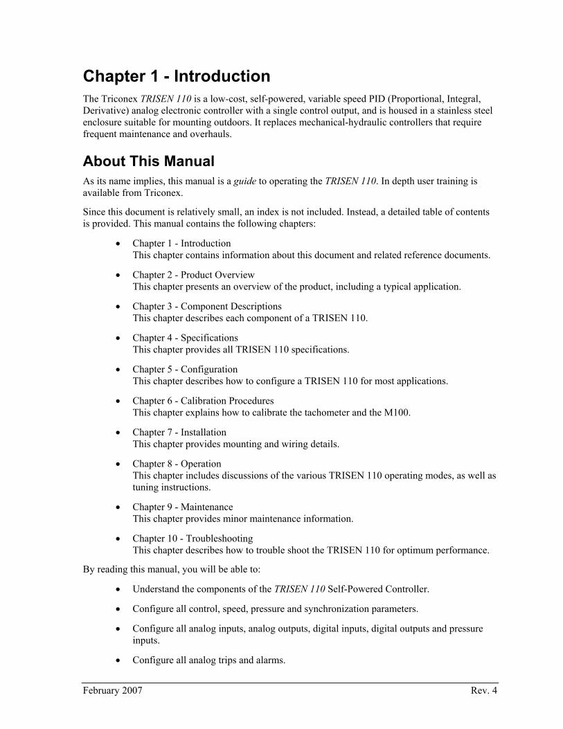
Chapter 1 - Introduction The Triconex TRISEN 110 is a low-cost, self-powered, variable speed PID (Proportional, Integral, Derivative) analog electronic controller with a single control output, and is housed in a stainless steel enclosure suitable for mounting outdoors. It replaces mechanical-hydraulic controllers that require frequent maintenance and overhauls.
About This Manual As its name implies, this manual is a guide to operating the TRISEN 110. In depth user training is available from Triconex.
Since this document is relatively small, an index is not included. Instead, a detailed table of contents is provided. This manual contains the following chapters:
• Chapter 1 - Introduction This chapter contains information about this document and related reference documents.
• Chapter 2 - Product Overview This chapter presents an overview of the product, including a typical application.
• Chapter 3 - Component Descriptions This chapter describes each component of a TRISEN 110.
• Chapter 4 - Specifications This chapter provides all TRISEN 110 specifications.
• Chapter 5 - Configuration This chapter describes how to configure a TRISEN 110 for most applications.
• Chapter 6 - Calibration Procedures This chapter explains how to calibrate the tachometer and the M100.
• Chapter 7 - Installation This chapter provides mounting and wiring details.
• Chapter 8 - Operation This chapter includes discussions of the various TRISEN 110 operating modes, as well as tuning instructions.
• Chapter 9 - Maintenance This chapter provides minor maintenance information.
• Chapter 10 - Troubleshooting This chapter describes how to trouble shoot the TRISEN 110 for optimum performance.
By reading this manual, you will be able to:
• Understand the components of the TRISEN 110 Self-Powered Controller.
• Configure all control, speed, pressure and synchronization parameters.
• Configure all analog inputs, analog outputs, digital inputs, digital outputs and pressure inputs.
• Configure all analog trips and alarms.
February 2007 Rev. 4

12 TRISEN 110 Self-Powered Controller Operations Guide
Documentation Conventions This manual uses the following typographic conventions:
Example Description
NOTE Notes contain supplementary information.
CAUTION! This symbol precedes information about potential equipment damage.
WARNING! This symbol precedes information about potential personnel hazards.
User Experience Prerequisites To effectively use the TRISEN 110, users should have some experience with the use of digital or analog control systems, or have an instrumentation background.
Experience with turbine control systems and operations within a plant environment are helpful, though not required.
Product and Training Information To obtain information about Triconex products and in-house and on-site training, see the Triconex Web site or contact the regional customer center.
Web Site
http://www.triconex.com
Technical Support Customers in the U.S. and Canada can obtain technical support from the Customer Satisfaction Center (CSC) at the numbers below. International customers should contact their regional support center.
Requests for support are prioritized as follows:
Emergency requests are given the highest priority
Requests from participants in the System Watch Agreement (SWA) and customers with purchase order or charge card authorization are given next priority
All other requests are handled on a time-available basis
If you require emergency or immediate response and are not an SWA participant, you may incur a charge. Please have a purchase order or credit card available for billing.
Telephone
Toll-free number 866-746-6477, or
Toll number 508-549-2424 (outside U.S.)
Fax
Toll number 508-549-4999
February 2007 Rev. 4

Chapter 1 - Introduction 13
Web Site
http://customernet.triconex.com (registration required)
Reference Documents Documentation provided with other components of a system containing a TRISEN 110.
February 2007 Rev. 4

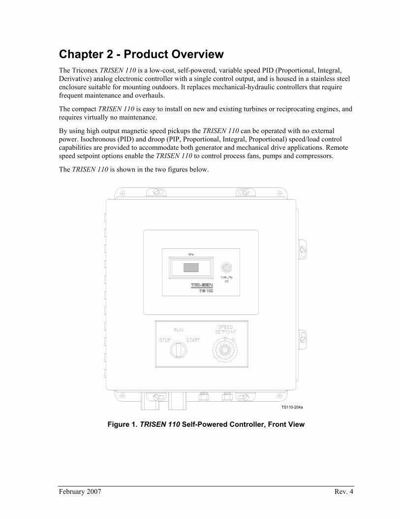
Chapter 2 - Product Overview The Triconex TRISEN 110 is a low-cost, self-powered, variable speed PID (Proportional, Integral, Derivative) analog electronic controller with a single control output, and is housed in a stainless steel enclosure suitable for mounting outdoors. It replaces mechanical-hydraulic controllers that require frequent maintenance and overhauls.
The compact TRISEN 110 is easy to install on new and existing turbines or reciprocating engines, and requires virtually no maintenance.
By using high output magnetic speed pickups the TRISEN 110 can be operated with no external power. Isochronous (PID) and droop (PIP, Proportional, Integral, Proportional) speed/load control capabilities are provided to accommodate both generator and mechanical drive applications. Remote speed setpoint options enable the TRISEN 110 to control process fans, pumps and compressors.
The TRISEN 110 is shown in the two figures below.
TS110-204a
Figure 1. TRISEN 110 Self-Powered Controller, Front View
February 2007 Rev. 4

16 TRISEN 110 Self-Powered Controller Operations Guide
TS110-204
Figure 2. TRISEN 110 Self-Powered Controller, Inside View
Features • No external operating power required
• Isochronous and droop speed control
• Dual pickup selector circuit, with lost signal indication
• Electronic overspeed protection
• Overspeed test
• Digital tachometer speed readout
• Three startup options
• Local and remote shutdown
• Local speed setpoint
• 4 to 20 mA or 3 to 15 PSIG remote speed setpoint options
• Broader speed control range than any mechanical governor
• Modular board design, which allows replacement of circuit board without removal of field wiring
February 2007 Rev. 4
Chapter 2 - Product Overview 17
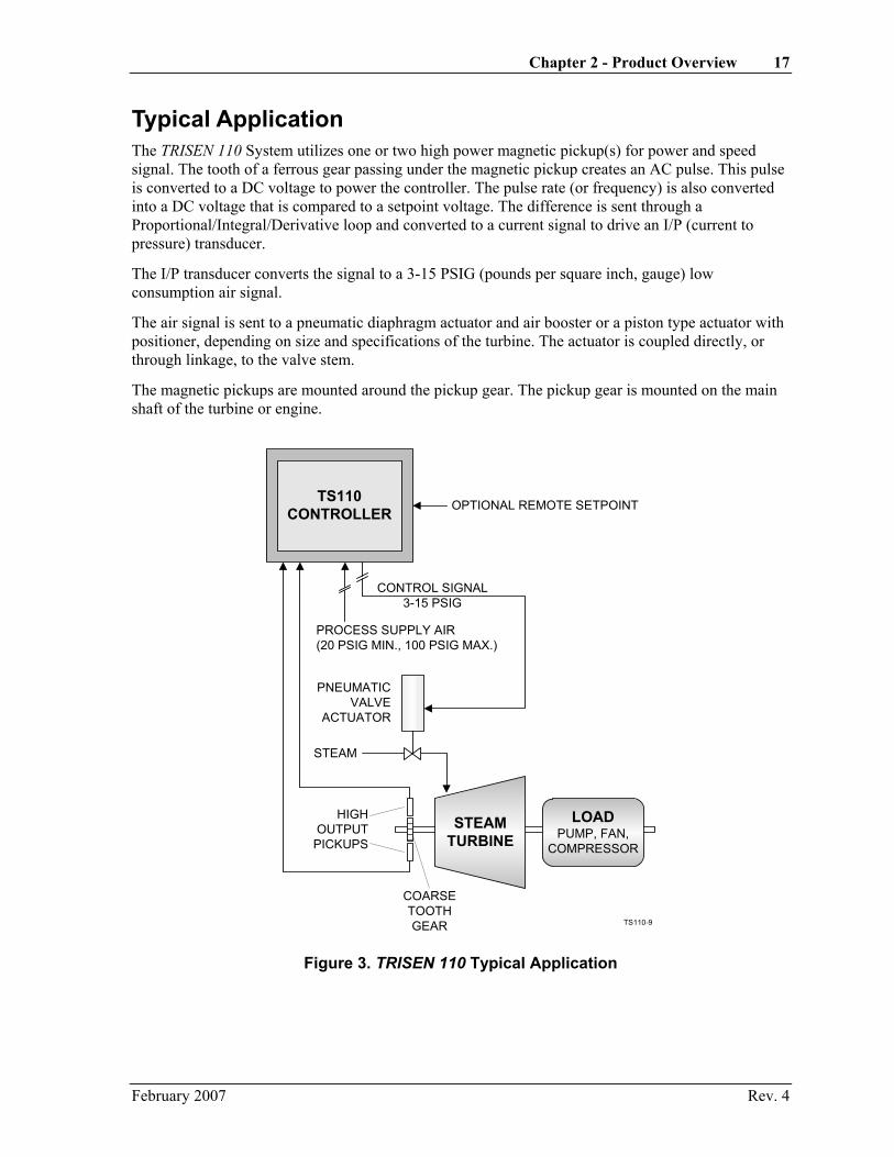
Typical Application The TRISEN 110 System utilizes one or two high power magnetic pickup(s) for power and speed signal. The tooth of a ferrous gear passing under the magnetic pickup creates an AC pulse. This pulse is converted to a DC voltage to power the controller. The pulse rate (or frequency) is also converted into a DC voltage that is compared to a setpoint voltage. The difference is sent through a Proportional/Integral/Derivative loop and converted to a current signal to drive an I/P (current to pressure) transducer.
The I/P transducer converts the signal to a 3-15 PSIG (pounds per square inch, gauge) low consumption air signal.
The air signal is sent to a pneumatic diaphragm actuator and air booster or a piston type actuator with positioner, depending on size and specifications of the turbine. The actuator is coupled directly, or through linkage, to the valve stem.
The magnetic pickups are mounted around the pickup gear. The pickup gear is mounted on the main shaft of the turbine or engine.
TS110CONTROLLER
STEAMTURBINE
LOADPUMP, FAN,
COMPRESSOR
PNEUMATICVALVE
ACTUATOR
STEAM
HIGHOUTPUT
PICKUPS
COARSETOOTHGEAR
CONTROL SIGNAL3-15 PSIG
PROCESS SUPPLY AIR(20 PSIG MIN., 100 PSIG MAX.)
OPTIONAL REMOTE SETPOINT
TS110-9
Figure 3. TRISEN 110 Typical Application
February 2007 Rev. 4

18 TRISEN 110 Self-Powered Controller Operations Guide
Components The Triconex TRISEN 110 consists of the following components:
• An adjustable timebase digital tachometer to display speed
• A PICKUPS OK LED
• A STOP/RUN/START switch (actuator)
• A local SPEED SETPOINT control (potentiometer)
• An M100 self-powered electronic controller assembly (The termination board is visible. It is hinged, and when the two screws are removed, it lifts up to reveal the circuit board below.)
• M100 terminal strip
• An auxiliary terminal block for wiring external remote run or start with 4 spare sets of terminals for customer use
• A 9 V battery holder
• An overspeed test switch
• An I/P transducer
• Input I/P air fitting
• Output I/P air fitting
• Field wiring conduit connections
• Purge air fitting
• Pneumatic Setpoint Fitting
• A stainless steel housing, which can be surface mounted near the turbine
• Up to 2 special high-output magnetic speed pickups, and standard interconnect cables
These components are shown in the following figures, and are described in detail in Chapter 3.
February 2007 Rev. 4

Chapter 2 - Product Overview 19
TRISENTS110
RPM
STOP
RUN
START
SPEEDSETPOINT
PICKUPSOK
TS110-5
Digital Tachometer
Pickup StatusLED
STOP/RUN/STARTSwitch
Speed setpointpotentiometer
Figure 4. TRISEN 110 Front View, Component Locations
February 2007 Rev. 4

20 TRISEN 110 Self-Powered Controller Operations Guide
6
16
5
8
10
9
7
13 11
M100
TS110-6
15 12 14
5 M100 controller assembly
6 M100 terminal strip
7 Auxiliary terminal strip
8 9V battery compartment
9 Overspeed test switch
10 I/P transducer
11 Input I/P air fitting
12 Output I/P air fitting
13 Field wiring conduit hubs
14 Purge air fitting
15 Remote pneumatic setpoint fitting
16 Stainless steel enclosure
Figure 5. TRISEN 110 Front View with Door Open, Component Locations
February 2007 Rev. 4

Chapter 2 - Product Overview 21
13
11 12
3 4
TS110-7
15 14
3 STOP/RUN/START switch
4 Speed setpoint potentiometer
11 Input I/P air fitting
12 Output I/P air fitting
13 Field wiring conduit hubs
14 Purge air fitting
15 Remote pneumatic setpoint fitting
Figure 6. TRISEN 110 Bottom View, Component Locations
February 2007 Rev. 4

22 TRISEN 110 Self-Powered Controller Operations Guide
BOTTOM VIEW
FRONT VIEW
TOP VIEW
0.250 ± 0.003
0.750, +0.025, -0.000
JAM NUT
5/8-18 UNF-2A THD 4.000 ± 0.015
5.093 REF
1.093 REF
AB
TS110-8
Figure 7. Special High-Output Magnetic Speed Pickup
February 2007 Rev. 4
Chapter 3 - Component Descriptions This chapter contains descriptions of the TRISEN 110 components, as outlined in Chapter 2. Refer to the previous figures for locations of these components.
3.1 Digital Tachometer The digital tachometer supplied with the TRISEN 110 is a 4-digit, configurable tachometer. It can be configured for any number of gear teeth. Older units were configured using DIP switches on the back of the tachometer, while currently shipping units are configured using push buttons.
NOTE: The gear must have a diametrical pitch of 8 or less for use with the special magnetic speed pickups.
3.2 PICKUPS OK LED This LED flashes every three seconds to indicate that both magnetic pickups are working properly. If one pickup fails, the LED will no longer flash, thus indicating a pickup failure.
3.3 STOP/RUN/START Switch The START position is used with a battery or a 4 to 20 mA signal to send an output current to the I/P transducer to open the control valve. In the RUN position, the output of the controller is allowed to pass to the I/P transducer. In the STOP position the output of the controller is set to minimum.
3.4 Local SPEED SETPOINT Control This control is a ten-turn potentiometer with a numbered dial and a locking tab. The fully clockwise position yields maximum governor speed. The numbers on the face of the dial (1-10) represent a percentage of the governing range, 1.0 being 10% and 10.0 being 100%.
EXAMPLE: Min Governor = 3400 RPM = 0.0
Max Governor = 3600 RPM = 10.0
50 percent Governor Range = 3500 RPM = 5.0
NOTE: The local speed setpoint can work in conjunction with the remote speed setpoint.
February 2007 Rev. 4

24 TRISEN 110 Self-Powered Controller Operations Guide
3.5 M100 Controller Assembly The M100 controller assembly is located inside the TRISEN 110, top left side. The termination board, which is visible, provides terminal strips for connection of field wiring. This board is hinged, and when the two screws are removed, it lifts up to reveal the circuit board below. The circuit board contains all of the jumpers, potentiometers, and test points necessary to configure the TRISEN 110 for a particular application.
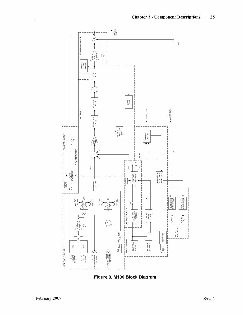
Refer to the figures below and on the following page for the general appearance and a block diagram of the M100 controller assembly.
1 +
2 -
3 +
4 -
5 +
6 -
7 +
8 -
9 +
10 -
11+
12 +
13 -
14 +
15 CW
16 W
17 CCW
18 +
19 -
1
2
3
4
5
6
7
8
9
10
11
+ 12
- 13
+ 14
- 15
16
+ 17
- 18
19
GAIN
DERIV
INTEGRAL
OVER
SPEED
TEST
RST
OVERSPEED
REMOTE
SETPNT
ANA
DIG
TACH
EXT
PWR
REM
STRT
MAX
FUEL
UNDER
SPEED
SWITCH
SPEED
LOOP
TUNING
REMOTESETPOINT
3 - 15PSIG
M100SELF-POWERED
GOVERNOR
TRISEN
TB2TB1
CW
CW
SWITCH
RUN
PICKUPS
OK
LOCAL
SET
REM
SET
I/P
PICKUP2
PICKUP1
TS110-4 TRI-SEN Systems, Inc.
La Marque, TX U.S.A.
ASSY 90-0360AW
90-0358
1
3
5
7
9
2
4
6
8
10
J1
W11
W7
W10
W81
3
2
W5
W11 3
W9 W4
W31 3
W21 3
W6
TS110-200
R12
1
R60
R59
R65
R64
R32
R33
R44
R24
R23
R82
R83
R101 R102
R117
R116
R115
TP7 TP8
TP4
TP9
TP6
TP5
TP3
TP1
TP2
GND
M100 Termination Board M100 Circuit Board
Figure 8. M100 Controller Assembly
February 2007 Rev. 4
Chapter 3 - Component Descriptions 25
4-20
mA
REM
OTE
SETP
OIN
T
3-15
PS
IR
EMO
TESE
TPO
INT
REM
OTE
PO
TEN
TIO
MET
ER
SETP
OIN
T
FREQ
UE
NC
YTO
VO
LTAG
EC
ON
VE
RTE
R
I / V
P / V
OV
ER
SP
EE
DTE
ST
HI/L
O S
ELE
CT
LOG
IC W
5
SE
TPO
INT
AC
TIO
N
SET
POIN
TA
MP
MA
X G
OV
MIN
GO
V
SET
POIN
TA
MP
MA
X G
OV
MIN
GO
V
W1
W2
W3
LOC
AL
PO
TEN
TIO
MET
ER
SE
TPO
INT
?
W7
RE
MO
TES
TAR
T LO
GIC
W4
MA
GN
ETI
CP
ICK
UP
#1
MA
GN
ETI
CP
ICK
UP
#2 P
ICKU
PS
OK
VO
LTA
GE
DO
UB
LER
S &
FILT
ERS
PU
LSE
SE
LEC
TLO
GIC
VOLT
AGE
REG
ULA
TIO
N
W6
EX
TER
NA
LP
OW
ER
OV
ER
SPE
ED
CO
MP
AR
ISO
N
UN
DE
RSP
EED
CO
MP
AR
ISO
N
STA
RTU
PP
ERM
ITD
IGIT
AL T
ACH
AN
ALO
G T
AC
HA
LAR
M
ALA
RM
+5V
TP3
TP2
REM
OTE
STA
RT
?E
RR
OR
AM
P
TP6
+ -
-
-
DE
RIV
ATI
VE
R11
3IN
TEG
RA
LR
4115
RED
UC
ED
GA
IN B
AN
DR
102
DR
OO
PR
101
?G
AIN
R11
7
OU
TPU
TC
ON
TRO
LA
CTI
ON
W8
V /
I
CU
RR
EN
TO
UTP
UT
MAX
/MIN
OU
TPU
TR
82, R
83
+-
MAX
STA
RT
OU
TPU
T
+5 -V
TP4
+
+
R44
PO
WE
R S
UP
PLY
SP
EE
DS
WIT
CH
ES
SP
EE
D S
IGN
AL
SE
TPO
INT
CIR
CU
IT
REM
OTE
STA
RT
PID
BLO
CK
CU
RR
EN
T D
RIV
ER
TS11
0-1
Figure 9. M100 Block Diagram
February 2007 Rev. 4
26 TRISEN 110 Self-Powered Controller Operations Guide
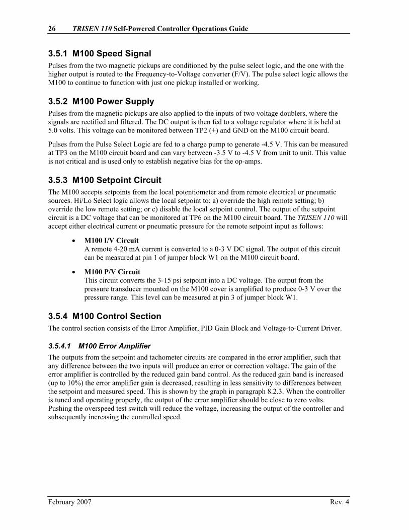
3.5.1 M100 Speed Signal Pulses from the two magnetic pickups are conditioned by the pulse select logic, and the one with the higher output is routed to the Frequency-to-Voltage converter (F/V). The pulse select logic allows the M100 to continue to function with just one pickup installed or working.
3.5.2 M100 Power Supply Pulses from the magnetic pickups are also applied to the inputs of two voltage doublers, where the signals are rectified and filtered. The DC output is then fed to a voltage regulator where it is held at 5.0 volts. This voltage can be monitored between TP2 (+) and GND on the M100 circuit board.
Pulses from the Pulse Select Logic are fed to a charge pump to generate -4.5 V. This can be measured at TP3 on the M100 circuit board and can vary between -3.5 V to -4.5 V from unit to unit. This value is not critical and is used only to establish negative bias for the op-amps.
3.5.3 M100 Setpoint Circuit The M100 accepts setpoints from the local potentiometer and from remote electrical or pneumatic sources. Hi/Lo Select logic allows the local setpoint to: a) override the high remote setting; b) override the low remote setting; or c) disable the local setpoint control. The output of the setpoint circuit is a DC voltage that can be monitored at TP6 on the M100 circuit board. The TRISEN 110 will accept either electrical current or pneumatic pressure for the remote setpoint input as follows:
• M100 I/V Circuit A remote 4-20 mA current is converted to a 0-3 V DC signal. The output of this circuit can be measured at pin 1 of jumper block W1 on the M100 circuit board.
• M100 P/V Circuit This circuit converts the 3-15 psi setpoint into a DC voltage. The output from the pressure transducer mounted on the M100 cover is amplified to produce 0-3 V over the pressure range. This level can be measured at pin 3 of jumper block W1.
3.5.4 M100 Control Section The control section consists of the Error Amplifier, PID Gain Block and Voltage-to-Current Driver.
3.5.4.1 M100 Error Amplifier The outputs from the setpoint and tachometer circuits are compared in the error amplifier, such that any difference between the two inputs will produce an error or correction voltage. The gain of the error amplifier is controlled by the reduced gain band control. As the reduced gain band is increased (up to 10%) the error amplifier gain is decreased, resulting in less sensitivity to differences between the setpoint and measured speed. This is shown by the graph in paragraph 8.2.3. When the controller is tuned and operating properly, the output of the error amplifier should be close to zero volts. Pushing the overspeed test switch will reduce the voltage, increasing the output of the controller and subsequently increasing the controlled speed.
February 2007 Rev. 4

Chapter 3 - Component Descriptions 27
3.5.4.2 M100 PID Gain Block The PID Gain Block consists of a derivative or rate amplifier stage followed by the proportional and integral gain stage. The output of the Error Amplifier is connected to the derivative input. As more derivative is adjusted in, the system becomes more sensitive to rate-of-change differences between the setpoint and measured speed.
As stated previously, any difference between the setpoint and measured speed will produce an error voltage. The integral or Reset Circuit integrates this voltage over time to produce an output to the actuator that steadily increases or decreases to correct for the difference. The rate that the output changes is controlled by the Reset adjustment.
The error voltage from the derivative stage is also amplified by the Proportional Gain circuit. The output of the controller for a given difference between the setpoint and measured speed signals will increase as the proportional gain increases. Consequently, increasing the proportional gain drives the amplifier into saturation sooner, thus limiting the range of errors over which it has control (proportional band). Decreasing the proportional gain increases the proportional band.
The output of the Proportional Gain / Reset Circuit can be measured at TP1. The voltage at this point is used to drive the Current Driver, and a small portion of this voltage is also fed back to the Error Amplifier through the Droop Control to allow Droop or load sharing.
The voltage at TP1 is monitored by the Maximum and Minimum Output switches. If the voltage is not within the window set by these two controls, the Proportional Gain/Reset Circuit is clamped by whichever switch is active to maintain the Minimum or Maximum Output limit.
3.5.4.3 M100 Voltage-to-Current Driver The Voltage-to-Current Driver converts the output of the PID Block into a 0-6 mA constant current source and represents the command to the I/P transducer. The current signal can be monitored by inserting a current meter in series with the RMT RUN terminals, on the auxiliary terminal strip below the M100 assembly.
NOTE: Models delivered before January 2007 used a 0–5 mA current for this signal.
3.5.5 M100 Speed Switches There are two speed switches in the M100 controller: an Underspeed Switch actuates when the measured speed drops below a user-defined setpoint; and an Overspeed Switch activates when the speed exceeds a preset, user-defined maximum speed.
3.5.5.1 M100 Underspeed Switch This switch monitors the voltage at TP4 which represents measured speed. When the speed drops below the setpoint voltage set by R65, a low current, 5-volt signal is applied to TB2:18. Typically this voltage may then be used to remotely start another M100. If the speed happens to rise above the setpoint again, the output will go back to zero.
The setpoint level can be monitored at TP9, and ranges from 0 V to 3.0 V.
February 2007 Rev. 4
28 TRISEN 110 Self-Powered Controller Operations Guide
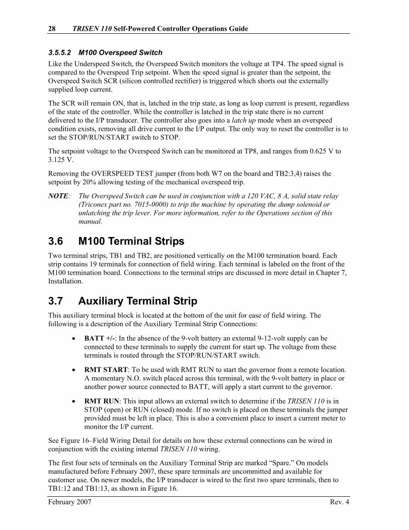
3.5.5.2 M100 Overspeed Switch Like the Underspeed Switch, the Overspeed Switch monitors the voltage at TP4. The speed signal is compared to the Overspeed Trip setpoint. When the speed signal is greater than the setpoint, the Overspeed Switch SCR (silicon controlled rectifier) is triggered which shorts out the externally supplied loop current.
The SCR will remain ON, that is, latched in the trip state, as long as loop current is present, regardless of the state of the controller. While the controller is latched in the trip state there is no current delivered to the I/P transducer. The controller also goes into a latch up mode when an overspeed condition exists, removing all drive current to the I/P output. The only way to reset the controller is to set the STOP/RUN/START switch to STOP.
The setpoint voltage to the Overspeed Switch can be monitored at TP8, and ranges from 0.625 V to 3.125 V.
Removing the OVERSPEED TEST jumper (from both W7 on the board and TB2:3,4) raises the setpoint by 20% allowing testing of the mechanical overspeed trip.
NOTE: The Overspeed Switch can be used in conjunction with a 120 VAC, 8 A, solid state relay (Triconex part no. 7015-0000) to trip the machine by operating the dump solenoid or unlatching the trip lever. For more information, refer to the Operations section of this manual.
3.6 M100 Terminal Strips Two terminal strips, TB1 and TB2, are positioned vertically on the M100 termination board. Each strip contains 19 terminals for connection of field wiring. Each terminal is labeled on the front of the M100 termination board. Connections to the terminal strips are discussed in more detail in Chapter 7, Installation.
3.7 Auxiliary Terminal Strip This auxiliary terminal block is located at the bottom of the unit for ease of field wiring. The following is a description of the Auxiliary Terminal Strip Connections:
• BATT +/-: In the absence of the 9-volt battery an external 9-12-volt supply can be connected to these terminals to supply the current for start up. The voltage from these terminals is routed through the STOP/RUN/START switch.
• RMT START: To be used with RMT RUN to start the governor from a remote location. A momentary N.O. switch placed across this terminal, with the 9-volt battery in place or another power source connected to BATT, will apply a start current to the governor.
• RMT RUN: This input allows an external switch to determine if the TRISEN 110 is in STOP (open) or RUN (closed) mode. If no switch is placed on these terminals the jumper provided must be left in place. This is also a convenient place to insert a current meter to monitor the I/P current.
See Figure 16–Field Wiring Detail for details on how these external connections can be wired in conjunction with the existing internal TRISEN 110 wiring.
The first four sets of terminals on the Auxiliary Terminal Strip are marked “Spare.” On models manufactured before February 2007, these spare terminals are uncommitted and available for customer use. On newer models, the I/P transducer is wired to the first two spare terminals, then to TB1:12 and TB1:13, as shown in Figure 16.
February 2007 Rev. 4

Chapter 3 - Component Descriptions 29
3.8 9-Volt Battery Holder This battery holder is located inside the TRISEN 110, top middle. It is to be used with a common 9-volt battery for the Battery Bypass Startup option. This battery will supply a small amount of current to the I/P to open the control valve of the turbine.
3.9 Overspeed Test Switch This switch is located below the 9-volt battery holder inside the TRISEN 110. The overspeed test switch is a spring-loaded, pushbutton designed for testing the mechanical overspeed trip mechanism. When depressed, the electronic overspeed trip is raised and the maximum governor setpoint is automatically raised an adjustable amount set by R121.
3.10 I/P Transducer The I/P transducer is located inside the TRISEN 110, right side. It converts the current signal from the controller to a 3 - 15 psi pneumatic signal with limited capacity. If a pneumatic actuator is used, it should have either a booster or a positioner.
The TRISEN 110 contains one of these I/P transducers:
• TRISEN 110s purchased before January 2007 contain a Series 771 I/P Transducer manufactured by Moore Products Company, which was acquired by Siemens in early 2000. For more information, visit http://www2.sea.siemens.com/
• TRISEN 110s purchased after January 2007 contain a Type-500X I/P Transducer manufactured by ControlAir, Inc. For more information, visit http://www.controlair.com/
3.11 Input I/P Air Fitting This fitting is used for supply air to the governor I/P. This air supply should be clean, dry and regulated to the pressures indicated in the Specifications section.
Use a minimum tube diameter of 3/8 inch, and step the tubing down to 1/4 inch to fit the 1/4-inch compression fitting.
3.12 Output I/P Air Fitting This fitting is a 1/4-inch compression fitting. This fitting is used to connect the output of the I/P with the final actuator (see paragraph 3.18). This line should be 1/4-inch tubing.
3.13 Field Wiring Conduit Connections Threaded conduit fitting to bring field wiring into the TRISEN 110 while retaining enclosure integrity.
3.14 Purge Air Fitting This is a 1/4-inch compression fitting which is provided for an optional air or nitrogen purge to keep a positive pressure on the box. This insures the inside of the box stays dry and clear of any dangerous gases.
Purge air is internally generated from I/P bleed air. If the cabinet must have purge air in addition to I/P bleed air, take care to avoid excessively pressurizing the cabinet, as this may affect I/P operation.
February 2007 Rev. 4
30 TRISEN 110 Self-Powered Controller Operations Guide
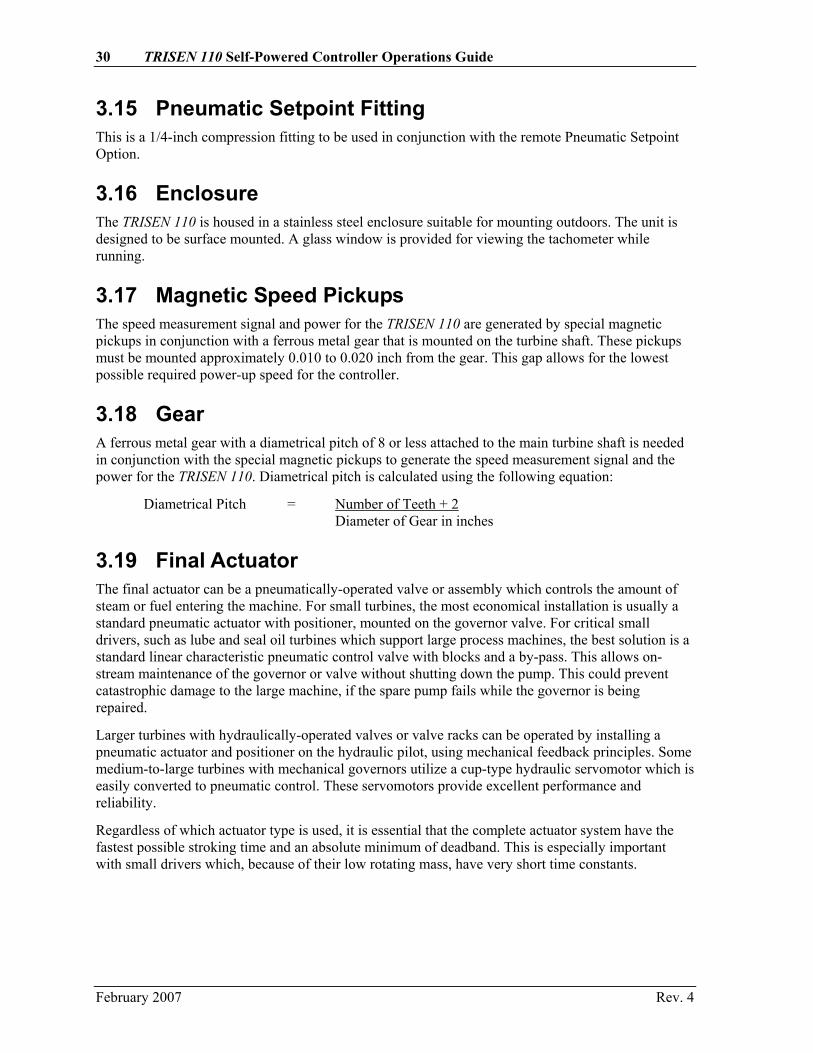
3.15 Pneumatic Setpoint Fitting This is a 1/4-inch compression fitting to be used in conjunction with the remote Pneumatic Setpoint Option.
3.16 Enclosure The TRISEN 110 is housed in a stainless steel enclosure suitable for mounting outdoors. The unit is designed to be surface mounted. A glass window is provided for viewing the tachometer while running.
3.17 Magnetic Speed Pickups The speed measurement signal and power for the TRISEN 110 are generated by special magnetic pickups in conjunction with a ferrous metal gear that is mounted on the turbine shaft. These pickups must be mounted approximately 0.010 to 0.020 inch from the gear. This gap allows for the lowest possible required power-up speed for the controller.
3.18 Gear A ferrous metal gear with a diametrical pitch of 8 or less attached to the main turbine shaft is needed in conjunction with the special magnetic pickups to generate the speed measurement signal and the power for the TRISEN 110. Diametrical pitch is calculated using the following equation:
Diametrical Pitch = Number of Teeth + 2 Diameter of Gear in inches
3.19 Final Actuator The final actuator can be a pneumatically-operated valve or assembly which controls the amount of steam or fuel entering the machine. For small turbines, the most economical installation is usually a standard pneumatic actuator with positioner, mounted on the governor valve. For critical small drivers, such as lube and seal oil turbines which support large process machines, the best solution is a standard linear characteristic pneumatic control valve with blocks and a by-pass. This allows on-stream maintenance of the governor or valve without shutting down the pump. This could prevent catastrophic damage to the large machine, if the spare pump fails while the governor is being repaired.
Larger turbines with hydraulically-operated valves or valve racks can be operated by installing a pneumatic actuator and positioner on the hydraulic pilot, using mechanical feedback principles. Some medium-to-large turbines with mechanical governors utilize a cup-type hydraulic servomotor which is easily converted to pneumatic control. These servomotors provide excellent performance and reliability.
Regardless of which actuator type is used, it is essential that the complete actuator system have the fastest possible stroking time and an absolute minimum of deadband. This is especially important with small drivers which, because of their low rotating mass, have very short time constants.
February 2007 Rev. 4

Chapter 4 - Specifications Inputs
Speed Sensor Triconex Part No. 7131-0004, 2 each (3 V rms at 15 mA, 200 - 10,000 Hz)
Gear Diametrical Pitch of 8 or less
Remote Start 4-20 mA or 5 V at 4 mA
Remote Power 9 Volts at 10 mA for startup only
Setpoints Local SPEED SETPOINT potentiometer on front panel and/or these remote setpoints: • User-supplied 100 kilo-ohm potentiometer • 4-20 mA current loop • 3-15 PSIG pneumatic
Remote Max. Fuel External 200 kOhm potentiometer (can be applied to limit maximum valve position)
Overspeed Test Open: Test; Closed: Normal
Start Switch Open: Normal; Closed: Start
Run Switch Open: Stop; Closed: Run
Reset Switch Open: Normal; Closed: Reset
Outputs
Actuator 3 to 15 PSIG at maximum rate of 2.0 SCFM at 20 PSIG supply
Overspeed Isolated SCR, 400 V max, 0.3 A max, 0.15 mA min
Low Speed 5 V at 4 mA when speed < low-speed switch setting
Analog Tachometer 0-50 µA
Digital Tachometer 5 V pulse
Adjustments
Local and Remote Speed Setpoint Minimum Governor, Maximum Governor,
(can be limited by Remote Max. Fuel Potentiometer)
Speed Trips & Alarms Overspeed Trip, Low Speed Switch
PID Control Gain, Derivative, Integral, Droop, Reduced Gain Band
Output Limits Local and Remote Maximum Output, Remote Start Maximum Output, Minimum Output, Overspeed Test
Tachometer F/V Calibration, Analog Tachometer Cal
February 2007 Rev. 4

32 TRISEN 110 Self-Powered Controller Operations Guide
Selections
Frequency Range 5 ranges from 200 to 10,000 Hz
Setpoint Logic Local and Remote; High or Low Select
Remote Setpoint Potentiometer, 4–20 mA, 3–15 PSIG; Direct/Reverse for current and pneumatic.
Power Source Speed Pickup or Battery (for startup only)
Remote Start Enable/Disable
Overspeed Test Open = Enabled / Shorted = Normal Operation
Control Action Direct or Reverse
Power Requirements
Speed Sensor 3 V rms at 15 mA, 200–10,000 Hz
External Battery 9 VDC, 10 mA (for startup only)
Performance
Control Action 0.1% Steady State
Droop Control 0–10%
Proportional Band 5–200%
Reset Time 0–10 Seconds/Repeat
Rate Time 0 –5 Seconds
Reduced Gain Band 0–10%
Frequency Range 200–10,000 Hz
I/P
Input Moore: 1–5 mA, ControlAir: 0–6 mA
Output 3–15 PSIG
Supply Pressure Moore: Normal: 20 PSIG (dry, filtered air) Minimum: 18 PSIG Maximum: 50 PSIG ControlAir: 18–100 PSIG
NOTE: Because the ControlAir I/P offers a wide range of allowable supply pressures, it is important that you specify your supply pressure when ordering the TRISEN 110 so that your unit is factory calibrated for the pressure you will be providing.
Output Capacity 2.0 SCFM at 20 PSIG supply
Maximum Air Loss Moore: Less than 0.2 SCFM at 20 PSIG supply ControlAir: 0.1 SCFM
February 2007 Rev. 4
Chapter 4 - Specifications 33
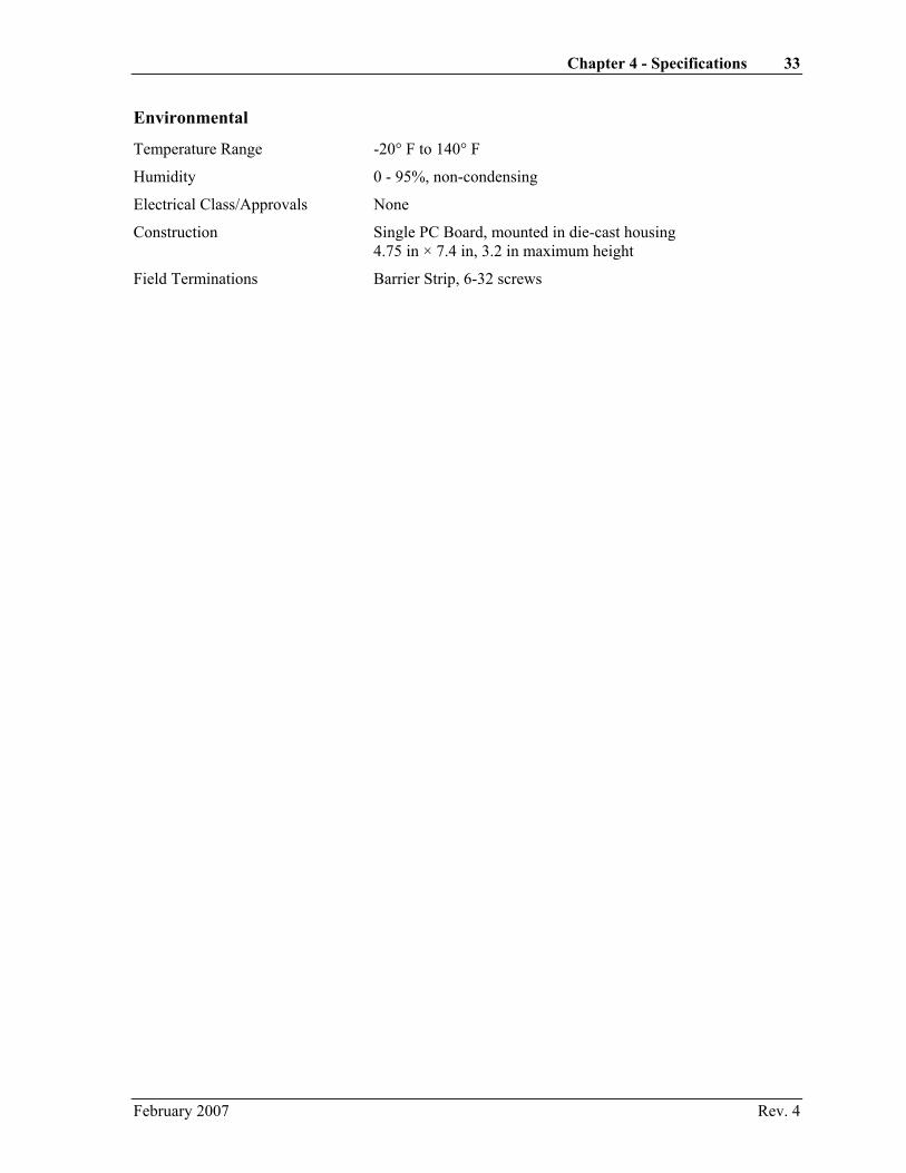
Environmental
Temperature Range -20° F to 140° F
Humidity 0 - 95%, non-condensing
Electrical Class/Approvals None
Construction Single PC Board, mounted in die-cast housing 4.75 in × 7.4 in, 3.2 in maximum height
Field Terminations Barrier Strip, 6-32 screws
February 2007 Rev. 4

Chapter 5 - Configuration Configuring the TRISEN 110 is accomplished by placing and/or removing jumpers on the M100 circuit board. (Refer to the figure on the following page.) The circuit board is accessed by removing the two screws from the termination board and lifting it up and to the left to expose the circuit board.
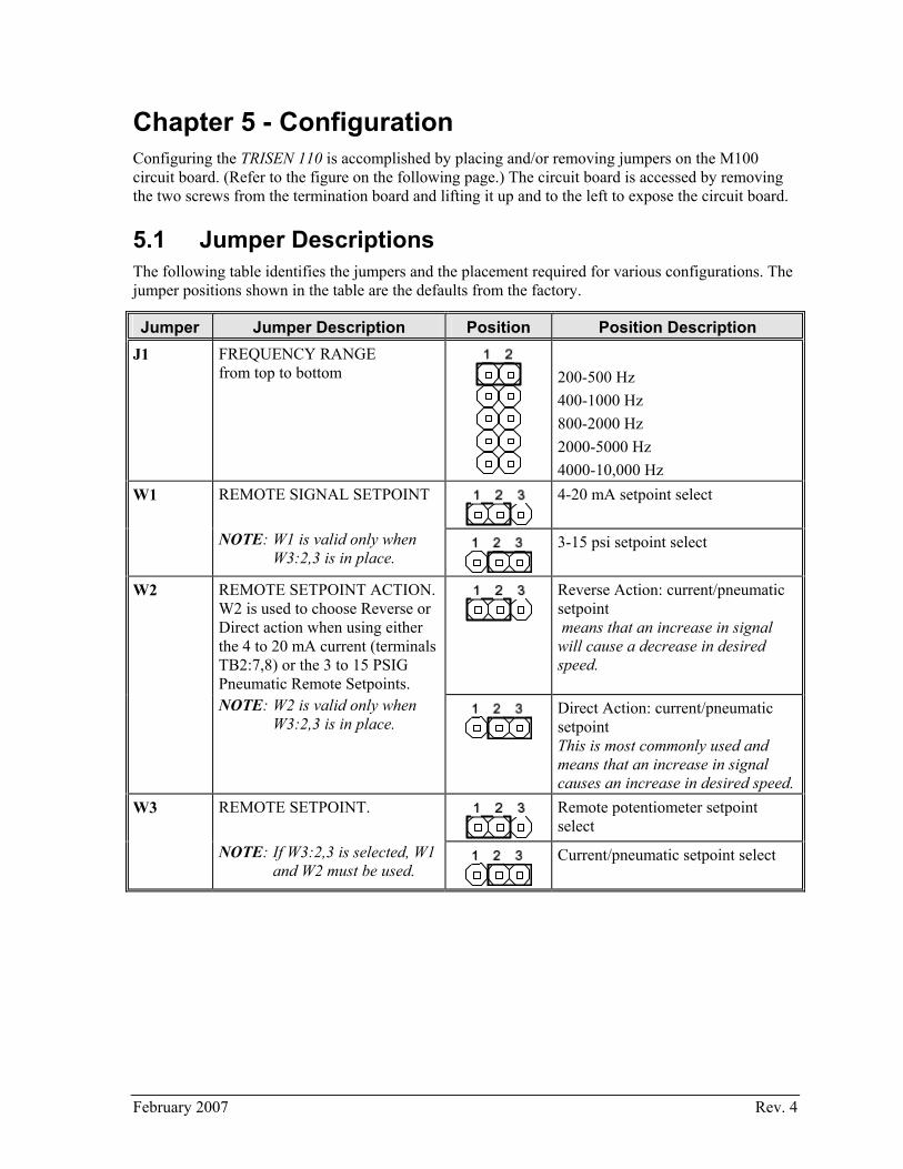
5.1 Jumper Descriptions The following table identifies the jumpers and the placement required for various configurations. The jumper positions shown in the table are the defaults from the factory.
Jumper Jumper Description Position Position Description J1 FREQUENCY RANGE
from top to bottom
200-500 Hz 400-1000 Hz 800-2000 Hz 2000-5000 Hz 4000-10,000 Hz
W1 REMOTE SIGNAL SETPOINT
4-20 mA setpoint select
NOTE: W1 is valid only when W3:2,3 is in place.
3-15 psi setpoint select
W2 REMOTE SETPOINT ACTION. W2 is used to choose Reverse or Direct action when using either the 4 to 20 mA current (terminals TB2:7,8) or the 3 to 15 PSIG Pneumatic Remote Setpoints.
Reverse Action: current/pneumatic setpoint means that an increase in signal will cause a decrease in desired speed.
NOTE: W2 is valid only when W3:2,3 is in place.
Direct Action: current/pneumatic setpoint This is most commonly used and means that an increase in signal causes an increase in desired speed.
W3 REMOTE SETPOINT.
Remote potentiometer setpoint select
NOTE: If W3:2,3 is selected, W1 and W2 must be used.
Current/pneumatic setpoint select
February 2007 Rev. 4

36 TRISEN 110 Self-Powered Controller Operations Guide
Jumper Jumper Description Position Position Description W4 REMOTE START. W4 is used in
conjunction with the 4 to 20 mA Remote Setpoint (terminals TB2:7,8). When W4 is installed, the governor can be started from the 4 to 20 MA current loop.
Remote start from 4-20 mA setpoint
WARNING! If this feature is applied to the TRISEN 110, care should be taken in training all personnel. The turbine will start with no one at the turbine/engine if the current loop is lost and regained. Refer to the remote start figure in paragraph 7.3.3.
NOTE: If W4 is installed, a (reset) switch must be installed in the Remote Setpoint 4 to 20 mA loop to momentarily interrupt the current loop to reset the Remote Start Feature for another startup.
W5 SETPOINT SELECT HIGH/LOW.
Local setpoint high select causes the local to override the remote when the local is set to a higher value.
NOTE: If W5 is not installed the Local Setpoint will be disabled.
Local setpoint low select causes the local to override the remote when the local is set to a lower value.
Local setpoint disabled
W6
M100 powered by magnetic pickup
W7 NOTE: This jumper is not used if overspeed test switch is installed across TB2:3,4.
Enable overspeed test
W8 CONTROL ACTION. W8 is used to choose reverse or direct control action to the final actuator.
Direct Control Action means that an increase in speed causes an increase in output to the actuator.
Reverse Control Action is most commonly used, and means that an increase in speed causes a decrease in output to the actuator. NOTE: Reverse Control Action is
more commonly used so that, as the speed of the machine increases, the valve is closed.
February 2007 Rev. 4

Chapter 5 - Configuration 37
Jumper Jumper Description Position Position Description W9 EXT +5 VOLT ENABLE.
+5 Volts are provided at TB2:12,13 for powering a solid state relay for overspeed trip. For more information refer to Paragraph 8.4. NOTE: If external power is applied
to TB2:12,13, W9 must be removed to prevent damage to the board.
W10 PNEUMATIC SETPOINT DISABLE.
Disable Pneumatic Setpoint NOTE: W10 and W11 must be
installed if the pneumatic setpoint is not used.
W11 PNEUMATIC SETPOINT DISABLE.
Disable Pneumatic Setpoint NOTE: W10 and W11 must be
installed if the pneumatic setpoint is not used.
February 2007 Rev. 4

38 TRISEN 110 Self-Powered Controller Operations Guide
TRI-SEN Systems, Inc.La Marque, TX U.S.A.
ASSY 90-0360AW
90-0358
1
3
5
7
9
2
4
6
8
10
J1
W11
W7
W10
W81
3
2
W5
W11 3
W9 W4
W31 3
W21 3
W6
TS110-201
Figure 10. Calibration/Configuration Diagram - Jumpers
February 2007 Rev. 4
Chapter 5 - Configuration 39
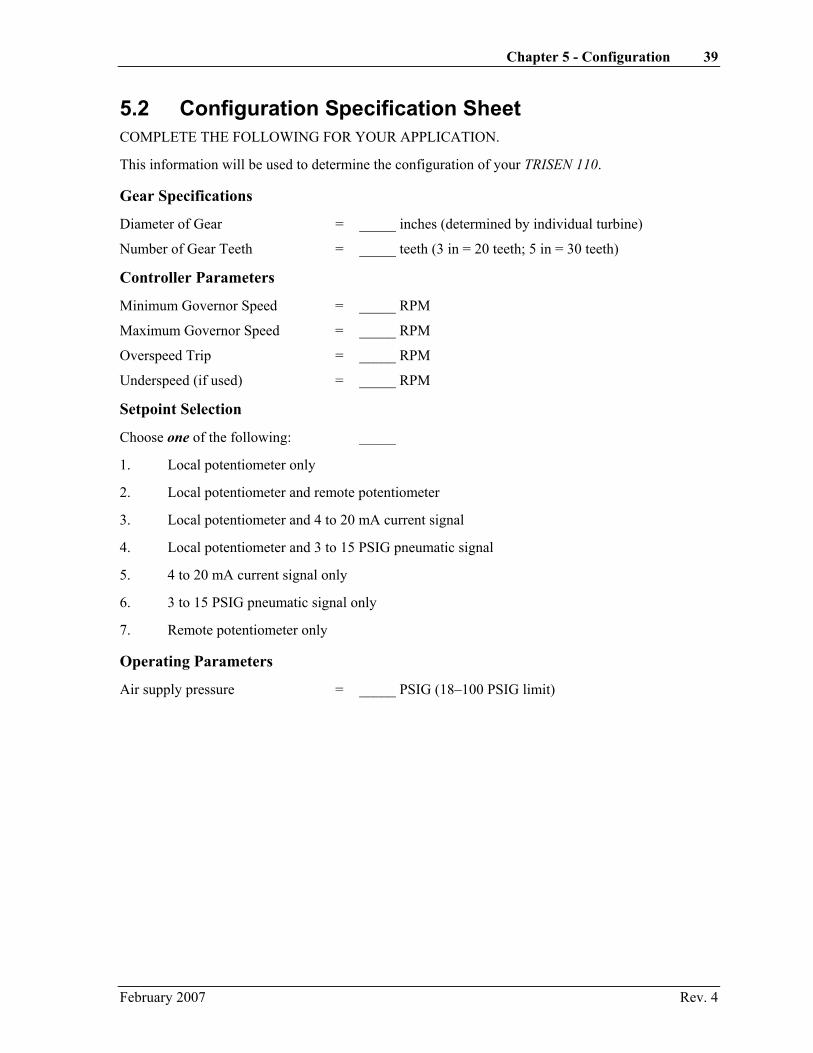
5.2 Configuration Specification Sheet COMPLETE THE FOLLOWING FOR YOUR APPLICATION.
This information will be used to determine the configuration of your TRISEN 110.
Gear Specifications
Diameter of Gear = _____ inches (determined by individual turbine)
Number of Gear Teeth = _____ teeth (3 in = 20 teeth; 5 in = 30 teeth)
Controller Parameters
Minimum Governor Speed = _____ RPM
Maximum Governor Speed = _____ RPM
Overspeed Trip = _____ RPM
Underspeed (if used) = _____ RPM
Setpoint Selection
Choose one of the following: _____
1. Local potentiometer only
2. Local potentiometer and remote potentiometer
3. Local potentiometer and 4 to 20 mA current signal
4. Local potentiometer and 3 to 15 PSIG pneumatic signal
5. 4 to 20 mA current signal only
6. 3 to 15 PSIG pneumatic signal only
7. Remote potentiometer only
Operating Parameters
Air supply pressure = _____ PSIG (18–100 PSIG limit)
February 2007 Rev. 4
40 TRISEN 110 Self-Powered Controller Operations Guide
The information completed on the Configuration Specification Sheet (previous page) will now be used to configure the TRISEN 110.
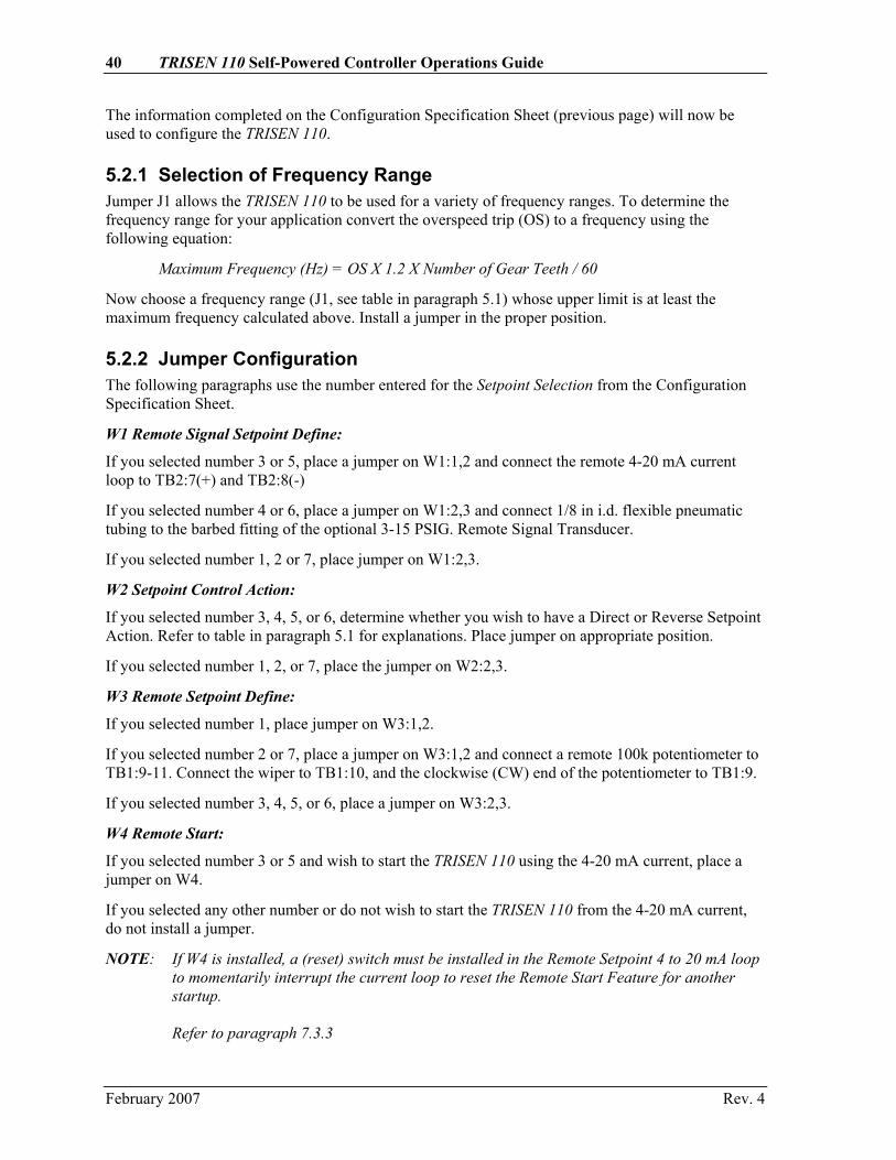
5.2.1 Selection of Frequency Range Jumper J1 allows the TRISEN 110 to be used for a variety of frequency ranges. To determine the frequency range for your application convert the overspeed trip (OS) to a frequency using the following equation:
Maximum Frequency (Hz) = OS X 1.2 X Number of Gear Teeth / 60
Now choose a frequency range (J1, see table in paragraph 5.1) whose upper limit is at least the maximum frequency calculated above. Install a jumper in the proper position.
5.2.2 Jumper Configuration The following paragraphs use the number entered for the Setpoint Selection from the Configuration Specification Sheet.
W1 Remote Signal Setpoint Define:
If you selected number 3 or 5, place a jumper on W1:1,2 and connect the remote 4-20 mA current loop to TB2:7(+) and TB2:8(-)
If you selected number 4 or 6, place a jumper on W1:2,3 and connect 1/8 in i.d. flexible pneumatic tubing to the barbed fitting of the optional 3-15 PSIG. Remote Signal Transducer.
If you selected number 1, 2 or 7, place jumper on W1:2,3.
W2 Setpoint Control Action:
If you selected number 3, 4, 5, or 6, determine whether you wish to have a Direct or Reverse Setpoint Action. Refer to table in paragraph 5.1 for explanations. Place jumper on appropriate position.
If you selected number 1, 2, or 7, place the jumper on W2:2,3.
W3 Remote Setpoint Define:
If you selected number 1, place jumper on W3:1,2.
If you selected number 2 or 7, place a jumper on W3:1,2 and connect a remote 100k potentiometer to TB1:9-11. Connect the wiper to TB1:10, and the clockwise (CW) end of the potentiometer to TB1:9.
If you selected number 3, 4, 5, or 6, place a jumper on W3:2,3.
W4 Remote Start:
If you selected number 3 or 5 and wish to start the TRISEN 110 using the 4-20 mA current, place a jumper on W4.
If you selected any other number or do not wish to start the TRISEN 110 from the 4-20 mA current, do not install a jumper.
NOTE: If W4 is installed, a (reset) switch must be installed in the Remote Setpoint 4 to 20 mA loop to momentarily interrupt the current loop to reset the Remote Start Feature for another startup. Refer to paragraph 7.3.3
February 2007 Rev. 4
Chapter 5 - Configuration 41
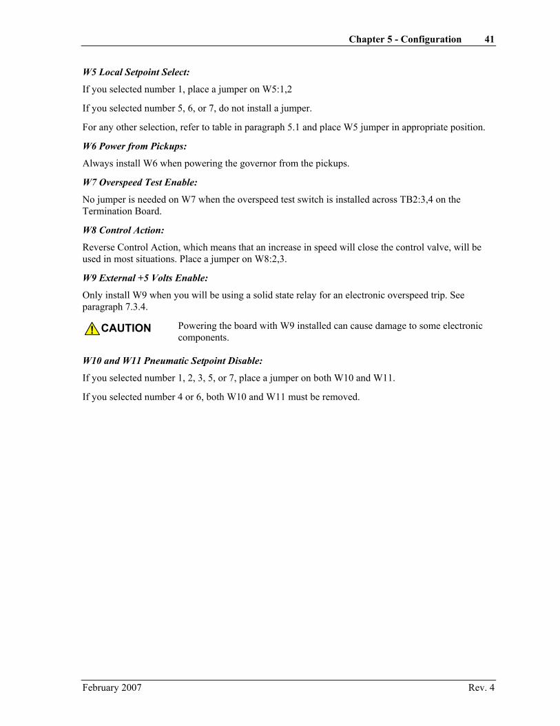
W5 Local Setpoint Select:
If you selected number 1, place a jumper on W5:1,2
If you selected number 5, 6, or 7, do not install a jumper.
For any other selection, refer to table in paragraph 5.1 and place W5 jumper in appropriate position.
W6 Power from Pickups:
Always install W6 when powering the governor from the pickups.
W7 Overspeed Test Enable:
No jumper is needed on W7 when the overspeed test switch is installed across TB2:3,4 on the Termination Board.
W8 Control Action:
Reverse Control Action, which means that an increase in speed will close the control valve, will be used in most situations. Place a jumper on W8:2,3.
W9 External +5 Volts Enable:
Only install W9 when you will be using a solid state relay for an electronic overspeed trip. See paragraph 7.3.4.
CAUTION! Powering the board with W9 installed can cause damage to some electronic components.
W10 and W11 Pneumatic Setpoint Disable:
If you selected number 1, 2, 3, 5, or 7, place a jumper on both W10 and W11.
If you selected number 4 or 6, both W10 and W11 must be removed.
February 2007 Rev. 4

Chapter 6 - Calibration Procedures
6.1 Digital Tachometer The TRISEN 110 controls from the frequency received from the pickups and gear. This frequency is related to the speed of the gear turning on the shaft and the number of teeth on the gear. The digital tachometer converts this frequency to RPM to allow the user to see the speed from the display window.
The TRISEN 110 uses one of two digital tachometers, depending on date of manufacture. Units manufactured prior to October, 2003 use the Red Lion DT6 digital tachometer. It is identified by a removable plastic cover on its back side, with DIP switches present underneath the cover. Newer units use the Red Lion DT9 digital tachometer. It is identified by two buttons marked “PAR” and “SEL” on the tachometer face: There is no removable cover on the back side; instead, there is a product label with “DT9” marked on it. The calibration procedure is different for each of the two tachometers.
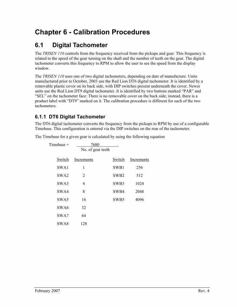
6.1.1 DT6 Digital Tachometer The DT6 digital tachometer converts the frequency from the pickups to RPM by use of a configurable Timebase. This configuration is entered via the DIP switches on the rear of the tachometer.
The Timebase for a given gear is calculated by using the following equation
Timebase = 7680 No. of gear teeth
Switch Increments Switch Increments
SWA1 1 SWB1 256
SWA2 2 SWB2 512
SWA3 4 SWB3 1024
SWA4 8 SWB4 2048
SWA5 16 SWB5 4096
SWA6 32
SWA7 64
SWA8 128
February 2007 Rev. 4

44 TRISEN 110 Self-Powered Controller Operations Guide
EXAMPLE: Find the appropriate DIP switch setting for a desired display reading with a 20-tooth gear.
TB = 7680 = 384 20 TB = 384
DIP SWB1 - 256 Needed = 128
DIP SWA8 - 128 Needed = 0
Set SWB1, SWA8 to the ON position.
Frequency Doubling
DIP switch SWB6 is the frequency doubling disable switch. This switch is set to the OFF position at the factory. SWB6 should always remain in the OFF position since this position allows for the fastest update time without sacrificing accuracy.
NOTE: If SWB6 is in the ON position, the RPM on the digital tachometer will read one-half of the actual RPM.
Decimal Point Selection
The selection of Decimal Point is accomplished by DIP switches SWB7 and SWB8. The following table shows which combination of switches is needed to obtain the desired decimal point location. The tachometer always has leading zero blanking.
SWB7 SWB8 DP Location
↑ ↑ factory test mode
↑ ↓ 0 (preset at factory)
↓ ↑ 0.0
↓ ↓ 0.00
NOTE: Decimal point will change only at the normal display update times.
February 2007 Rev. 4
Chapter 6 - Calibration Procedures 45
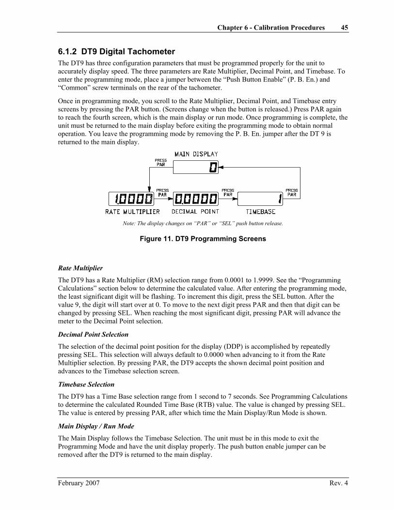
6.1.2 DT9 Digital Tachometer The DT9 has three configuration parameters that must be programmed properly for the unit to accurately display speed. The three parameters are Rate Multiplier, Decimal Point, and Timebase. To enter the programming mode, place a jumper between the “Push Button Enable” (P. B. En.) and “Common” screw terminals on the rear of the tachometer.
Once in programming mode, you scroll to the Rate Multiplier, Decimal Point, and Timebase entry screens by pressing the PAR button. (Screens change when the button is released.) Press PAR again to reach the fourth screen, which is the main display or run mode. Once programming is complete, the unit must be returned to the main display before exiting the programming mode to obtain normal operation. You leave the programming mode by removing the P. B. En. jumper after the DT 9 is returned to the main display.
Note: The display changes on “PAR” or “SEL” push button release.
Figure 11. DT9 Programming Screens
Rate Multiplier
The DT9 has a Rate Multiplier (RM) selection range from 0.0001 to 1.9999. See the “Programming Calculations” section below to determine the calculated value. After entering the programming mode, the least significant digit will be flashing. To increment this digit, press the SEL button. After the value 9, the digit will start over at 0. To move to the next digit press PAR and then that digit can be changed by pressing SEL. When reaching the most significant digit, pressing PAR will advance the meter to the Decimal Point selection.
Decimal Point Selection
The selection of the decimal point position for the display (DDP) is accomplished by repeatedly pressing SEL. This selection will always default to 0.0000 when advancing to it from the Rate Multiplier selection. By pressing PAR, the DT9 accepts the shown decimal point position and advances to the Timebase selection screen.
Timebase Selection
The DT9 has a Time Base selection range from 1 second to 7 seconds. See Programming Calculations to determine the calculated Rounded Time Base (RTB) value. The value is changed by pressing SEL. The value is entered by pressing PAR, after which time the Main Display/Run Mode is shown.
Main Display / Run Mode
The Main Display follows the Timebase Selection. The unit must be in this mode to exit the Programming Mode and have the unit display properly. The push button enable jumper can be removed after the DT9 is returned to the main display.
February 2007 Rev. 4
46 TRISEN 110 Self-Powered Controller Operations Guide
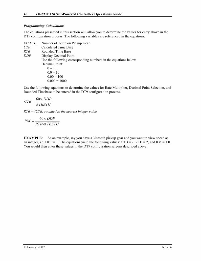
Programming Calculations
The equations presented in this section will allow you to determine the values for entry above in the DT9 configuration process. The following variables are referenced in the equations.
#TEETH Number of Teeth on Pickup Gear CTB Calculated Time Base RTB Rounded Time Base DDP Display Decimal Point Use the following corresponding numbers in the equations below Decimal Point: 0 = 1 0.0 = 10 0.00 = 100 0.000 = 1000
Use the following equations to determine the values for Rate Multiplier, Decimal Point Selection, and Rounded Timebase to be entered in the DT9 configuration process.
TEETH#DDPCTB ×
=60
RTB = (CTB) rounded to the nearest integer value
TEETH#RTBDDPRM
××
=60
EXAMPLE: As an example, say you have a 30-tooth pickup gear and you want to view speed as an integer, i.e. DDP = 1. The equations yield the following values: CTB = 2, RTB = 2, and RM = 1.0. You would then enter these values in the DT9 configuration screens described above.
February 2007 Rev. 4

Chapter 6 - Calibration Procedures 47
6.2 M100 Calibration Procedure Prerequisites
• 1. Equipment required for calibration: Digital multimeter (DMM) M115 simulator
• 2. Set potentiometers according to the table below. Refer to figure on following page.
Potentiometer Settings
POT FUNCTION SET R117 GAIN 2/3 CW R116 DERIVATIVE CCW R115 INTEGRAL 2/3 CW R121 O/S ADJUST CCW R102 REDUCED GAIN BAND CCW R101 DROOP CCW R60 OVERSPEED TRIP CW R59 ANALOG TACH CW R65 UNDERSPEED CCW R64 F/V CAL CCW R82 MAX OUTPUT LIMIT CW R83 MIN OUTPUT LIMIT CCW R32 MAX GOV (LOCAL) CCW R33 MIN GOV (LOCAL) CCW R24 MAX GOV (REMOTE) CCW R23 MIN GOV (REMOTE) CCW R44 MAX START OUTPUT CCW
• 3. Disconnect the following:
TB1:12 TB1:13 TB1:14 TB1:15
• 4. Connect the wires from the M115 as labeled.
• 5. M115 settings:
LOAD 1/3 CW LAG 1/3CW 0-2K TO 0-20K Set according to maximum frequency needed SIM-CALIB CALIB FREQ CCW (0.0 on turns counter) PWR OFF
February 2007 Rev. 4

48 TRISEN 110 Self-Powered Controller Operations Guide
TRI-SEN Systems, Inc.La Marque, TX U.S.A.
ASSY 90-0360AW
90-0358
1
3
5
7
9
2
4
6
8
10
J1
W11
W7
W10
W81
3
2
W5
W11 3
W9 W4
W31 3
W21 3
W6
TS110-202
R12
1
R60
R59
R65
R64
R32
R33
R44
R24
R23
R82
R83
R101 R102
R117
R116
R115
Figure 12. Calibration/Configuration Diagram - Potentiometers
February 2007 Rev. 4

Chapter 6 - Calibration Procedures 49
TRI-SEN Systems, Inc.La Marque, TX U.S.A.
ASSY 90-0360AW
90-03581
3
5
7
9
2
4
6
8
10
J1
W11
W7
W10
W81
3
2
W5
W11 3
W9 W4
W31 3
W21 3
W6
TS110-203
R12
1
R60
R59
R65
R64
R32
R33
R44
R24
R23
R82
R83
R101 R102
R117
R116
R115
TP7 TP8
TP4
TP9
TP6
TP5
TP3
TP1
TP2
GND
Figure 13. Calibration/Configuration Diagram - Test Points
February 2007 Rev. 4

50 TRISEN 110 Self-Powered Controller Operations Guide
Procedure • 1. Turn stop/run/start switch to stop.
• 2. Turn M115 power ON.
F/V Calibration
• 3. Adjust FREQ to generate the value of the maximum rpm as calculated in paragraph 5.2.1.
• 4. Connect DMM negative lead to GND, and positive lead to Test Point TP2. See figure on previous page. Reading should be 5 volts (5.0 to 5.2 volts).
• 5. Connect positive lead on DMM to TP4 and adjust R64 for 3.0 volts.
• 6. Switch STOP/RUN/START switch to run.
• 7. Set SIM-CALIB switch on M115 to SIM.
Local Potentiometer Calibration
• 8. If you selected number 5, 6 or 7 (on the configuration specification sheet, paragraph 5.2), go to remote signal calibration.
Minimum governor
• 9 If jumper W5 is not on W5:1,2, move it to that position.
• 10. Turn speed setpoint pot on TRISEN 110 CCW (0.0).
• 11. Adjust R33 until digital tachometer (DT) reads minimum governor.
Maximum Governor
• 12. Turn speed setpoint pot CW (10.0)
• 13. Adjust R32 until DT reads maximum governor.
NOTE: If W5 was moved, place it back in its original position.
Remote Signal Calibration
This calibration is not required if not using a remote setpoint. Minimum Governor
• 14. Make a note of the position of jumper W5 and remove it.
• 15. Apply a speed setpoint signal that is expected to produce minimum governor (4 mA, 3 PSIG or CCW on remote pot).
• 16. Adjust R23 until digital tachometer (DT) reads minimum governor.
Maximum Governor
• 17. Apply a speed setpoint that is expected to produce maximum governor (20 mA, 15 PSIG or CW on remote pot).
• 18. Adjust R24 until DT reads maximum governor.
• 19. If W5 was removed place it back to its original position.
February 2007 Rev. 4
Chapter 6 - Calibration Procedures 51
Overspeed Setpoint
• 20. Connect DMM negative lead to GND and the positive lead to TP7. This voltage will be approximately -3.5 volts. This indicates that the unit is not in overspeed trip.
• 21. Set M115 SIM-CALIB to CALIB and adjust calibrate pot to the overspeed setting.
• 22. DT should read the overspeed setting.
• 23. Turn R60 CCW until DMM reading goes from a negative voltage to approximately +5 volts.
• 24. Switch to STOP, and turn M115 power OFF.
• 25. Move M115 calibrate pot to slightly below the overspeed setting.
• 26. Switch to RUN, and turn M115 power ON.
• 27. Slowly turn freq pot CW while watching the DT, and confirm that the DMM reading goes to +5 volts at a DT reading of the overspeed value.
• 28. Switch to STOP and turn M115 power OFF.
• 29. Turn M115 freq pot CCW to 0.0.
Underspeed Switch
• 30. Connect the DMM positive lead to TB2:18, and the negative lead to TB2:19.
• 31. Switch to RUN and turn M115 power ON.
• 32. Set M115 freq pot to the UNDERSPEED TRIP setting and the SIM-CALIB switch to CALIB.
• 33. DT should read underspeed trip setting.
• 34. Turn R65 CW until DMM indicates +5 volts.
Mechanical Overspeed Test
• 35. Switch to STOP and turn M115 power OFF for about 5 seconds.
• 36. Set SIM/CAL switch to SIM.
• 37. Turn M115 power ON and switch to START momentarily (switch will revert back to RUN).
• 38. If you have problems starting the TRISEN 110, increase the LOAD and LAG on the M115. Always turn M115 power OFF for about 5 seconds between starts to allow the residual power to dissipate.
• 39. Push and hold the OVERSPEED TEST switch.
• 40. Adjust R121 to achieve the maximum rpm that you want to reach while testing the mechanical trip on the turbine.
Min/Max Output
• 41. Switch to STOP and turn the M115 power OFF.
February 2007 Rev. 4

52 TRISEN 110 Self-Powered Controller Operations Guide
• 42. Remove the jumper from the RMT RUN (terminals 9 and 10 on the auxiliary terminal strip).
• 43. Place DMM positive lead on terminal 9 and the negative lead on terminal 10.
• 44. Place the DMM in MA CURRENT mode.
• 45. Set the M115 SIM/CAL switch to CAL.
• 46. Switch to run and turn the M115 power ON.
• 47. Adjust the freq pot to slightly above maximum governor speed. This should make the current on the DMM integrate to about 0 mA.
• 48. Adjust R83 CW until the DMM reads 1 mA.
NOTE: If the current stays at 0 mA the governor may be in an overspeed trip condition. Make sure that the speed is adjusted below the overspeed trip setpoint. Turn the STOP/RUN/START switch to STOP and then back to RUN. This should reset the controller. Also check the DMM leads to insure that they are firmly attached and making a good connection.
• 49. Adjust the freq pot to slightly below minimum governor speed. This should make the current on the DMM integrate to about 6.5 mA.
• 50. Adjust R82 CCW until the DMM reads 5 mA.
You have now adjusted the controller to operate between 1 and 5 mA.
NOTE: After adjusting the min and max output, the M115 valve position will show 20% or more, unless the controller has tripped or the STOP/RUN/START switch is in the STOP position.
Simulation
• 51. Switch to STOP and turn M115 power OFF for about 5 seconds.
• 52. Set the SIM-CALIB switch to SIM.
• 53. Turn speed setpoint pot CCW (0.0).
• 54. Turn M115 power ON and switch to START momentarily (switch will revert back to RUN).
• 55. If you have problems starting the TRISEN 110, increase the LOAD and LAG on the M115. Always turn M115 power OFF for about 5 seconds between starts to allow the residual power to dissipate.
• 56. DT should read minimum governor speed.
• 57. Increase speed setpoint CW to 5.0. The valve meter on the M115 should deflect upward (open). The DT should read approximately mid-range.
• 58. Increase the load on the M115 and the valve should deflect further upward.
You have now tested the TRISEN 110 functionally, and it is ready to be configured to your application.
February 2007 Rev. 4
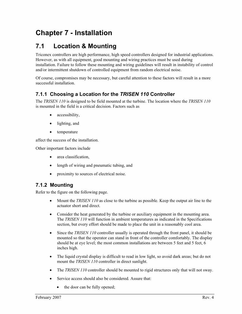
Chapter 7 - Installation
7.1 Location & Mounting Triconex controllers are high performance, high speed controllers designed for industrial applications. However, as with all equipment, good mounting and wiring practices must be used during installation. Failure to follow these mounting and wiring guidelines will result in instability of control and/or intermittent shutdown of controlled equipment from random electrical noise.
Of course, compromises may be necessary, but careful attention to these factors will result in a more successful installation.
7.1.1 Choosing a Location for the TRISEN 110 Controller The TRISEN 110 is designed to be field mounted at the turbine. The location where the TRISEN 110 is mounted in the field is a critical decision. Factors such as
• accessibility,
• lighting, and
• temperature
affect the success of the installation.
Other important factors include
• area classification,
• length of wiring and pneumatic tubing, and
• proximity to sources of electrical noise.
7.1.2 Mounting Refer to the figure on the following page.
• Mount the TRISEN 110 as close to the turbine as possible. Keep the output air line to the actuator short and direct.
• Consider the heat generated by the turbine or auxiliary equipment in the mounting area. The TRISEN 110 will function in ambient temperatures as indicated in the Specifications section, but every effort should be made to place the unit in a reasonably cool area.
• Since the TRISEN 110 controller usually is operated through the front panel, it should be mounted so that the operator can stand in front of the controller comfortably. The display should be at eye level; the most common installations are between 5 feet and 5 feet, 6 inches high.
• The liquid crystal display is difficult to read in low light, so avoid dark areas; but do not mount the TRISEN 110 controller in direct sunlight.
• The TRISEN 110 controller should be mounted to rigid structures only that will not sway.
• Service access should also be considered. Assure that:
• the door can be fully opened;
February 2007 Rev. 4

54 TRISEN 110 Self-Powered Controller Operations Guide
• the unit will not be subjected to steam or dripping water or other liquids; and
• that locating the Triconex controller in a given area will not be in violation of area classification.
• The I/P transducer is calibrated to operate while mounted vertically, that is, with the tachometer facing the operator and the conduit hubs on the bottom. If the TRISEN 110 is mounted in a different orientation, the I/P transducer will likely need to be recalibrated. Please contact the Triconex Customer Satisfaction Center or the I/P transducer manufacturer for information on how to recalibrate the transducer when mounting the TRISEN 110 in a non-standard orientation, and whether your mounting orientation is supported.
If any of these items is doubtful, consider another location.
February 2007 Rev. 4

Chapter 7 - Installation 55
TS110-206
Figure 14. Mounting Dimensions
February 2007 Rev. 4

56 TRISEN 110 Self-Powered Controller Operations Guide
7.2 Field Wiring for Standard Installation The TRISEN 110 System is shipped 90% pre-wired. The only field wiring required is for the magnetic pickups, and the remote speed setpoint, if used.
• Magnetic pickups and remote speed setpoint use shielded pairs of 16 - 18 AWG wires.
• Pickup #2 terminates on TB1-14 and TB1-15 with the shield on TB1-16.
• Pickup #1 terminates on TB1-17 and TB1-18 with the shield on TB1-19.
• The remote speed setpoint, if used, should be a 4 - 20 mA signal. The positive lead terminates on TB2-7; and the negative lead terminates on TB2-8 with the shield terminated on TB1-8.
• Connect TB1-8 to a suitable earth gound.
This wiring configuration is shown in the figure on the following page.
CONSULT THE FACTORY WHEN IN DOUBT ABOUT ANY INSTALLATION PROCEDURE.
WARNING! Have qualified personnel verify all wiring and connections against appropriate drawings prior to energizing the equipment. Incorrect wiring and/or connections can result in equipment damage.
CAUTION!
For installations in hazardous locations refer to the notes on the figures in this chapter.
February 2007 Rev. 4
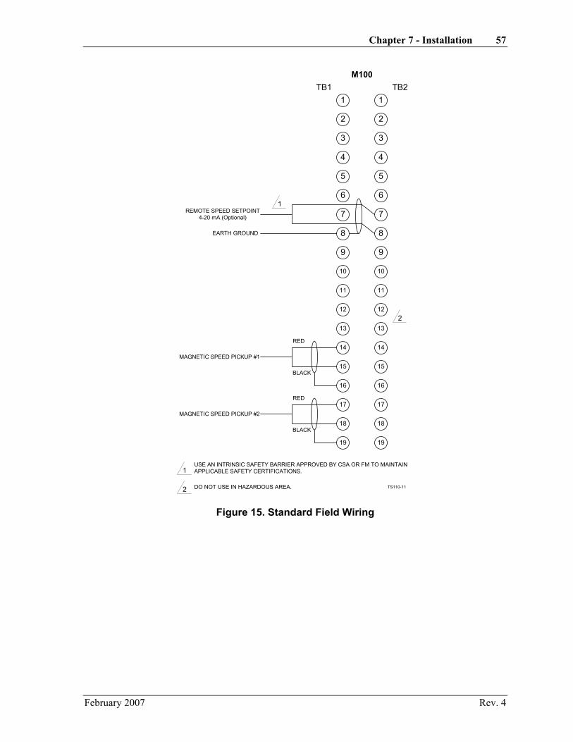
Chapter 7 - Installation 57
2
3
1
5
6
4
8
9
7
11
12
10
14
15
13
16
18
19
17
2
3
1
5
6
4
8
9
7
11
12
10
14
15
13
16
18
19
17
TB1 TB2
REMOTE SPEED SETPOINT4-20 mA (Optional)
EARTH GROUND
1
RED
BLACK
RED
BLACK
MAGNETIC SPEED PICKUP #1
MAGNETIC SPEED PICKUP #2
2
M100
1
2
USE AN INTRINSIC SAFETY BARRIER APPROVED BY CSA OR FM TO MAINTAINAPPLICABLE SAFETY CERTIFICATIONS.
DO NOT USE IN HAZARDOUS AREA. TS110-11
Figure 15. Standard Field Wiring
February 2007 Rev. 4

58 TRISEN 110 Self-Powered Controller Operations Guide
M100 Termination Board Wiring Details Refer to the table below and the figure on the following page for details concerning field wiring terminations on the M100 terminal strips.
Terminal Description
TB1:1,2 RUN SWITCH - Closed to run; open to stop. Opening this switch removes all electrical current to the I/P.
TB1:3,4 PICKUPS OK - An LED connected across these terminals as shown will flash periodically when both magnetic pickups are functioning.
TB1:5-7 LOCAL SET - A 10-turn, 100k-ohm potentiometer installed across these terminals provides the Local Setpoint.
TB1:8 GROUND - For terminating the shield around the Remote Potentiometer Setpoint wiring.
TB1:9-11 RMT SET - A 10-turn, 100k-ohm potentiometer installed across these terminals provides the Remote Potentiometer Setpoint. A shielded, three-wire cable should be used to connect the potentiometer, with the shield connected only to TB1:8. (Do not terminate other end of shield.)
TB1:12,13 I/P - current output signal from the M100 to the Current-to-Pneumatic converter
TB1:14-19 PICKUP 2 and PICKUP 1 - Connection for the two magnetic pickups. Each set of wires should be individually shielded, twisted pair, with the shields connected ONLY to TB1:16/TB1:19. (Do not connect shield at other end.)
TB2:1,2 O/S ALM - Alarm output indicating an over speed condition has occurred. The output is an SCR that remains latched on, even after M100 is powered down as long as external loop current flows.
TB2:3,4 OVERSPEED TEST - Open: raises electronic overspeed trip approximately 20% and increases governor range an adjustable amount. This is used to check external mechanical overspeed trip.
TB2:5,6 OVERSPEED RST - a normally open switch is placed across these terminals to reset the governor after an electronic overspeed.
TB2:7,8 REMOTE SETPNT - Input from remote 4-20 mA setpoint signal.
TB2:9-11 TACHOMETER - A 50 µA current meter connected across terminals 9 and 10 indicates analog speed. A digital tachometer (frequency counter) is connected across terminals 10 and 11. The digital tachometer signal is sufficient to drive most self-powered tachometers.
TB2:12,13 EXT PWR - External power input to M100 for test purposes only. Voltage must be 9-12 volts. When jumper W9 is in place, 5 V/4 mA is available at these terminals for tripping a solid state relay. See paragraph 7.3.2.
TB2:14,13 RMT STRT - Remote start input; applying 5 V to these terminals on an unpowered TRISEN 110 will cause a current to flow out of the I/P terminal (TB1:12). Once the unit is powered and controlling, the Remote Start signal is disabled internally. The Remote Start signal must be interrupted externally to restart a unit that has been powered down. This input is designed to work with the SPEED SWITCH output of another TRISEN 110.
TB2:15-17 MAX OUTPUT - A 200k-ohm potentiometer connected across these terminals allows the maximum output limit to be set externally. To use these terminals, R82 on the M100 board must be removed.
TB2:18,19 UNDERSPEED SWITCH - Output goes to 5 V when speed drops below the speed switch setpoint. This is a low-current signal designed to start a second TRISEN 110 (see RMT STRT above) in the event the first one drops below a specified speed.
February 2007 Rev. 4
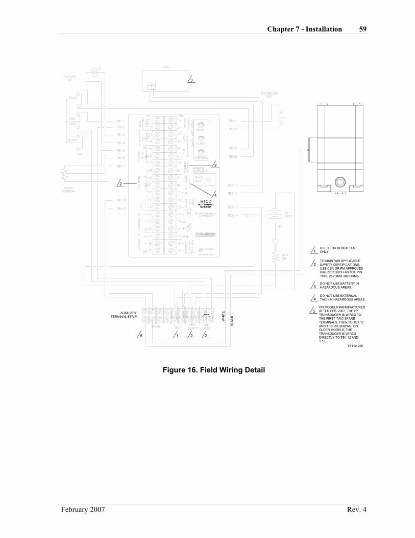
Chapter 7 - Installation 59
3
2
4
2
1 2 2
1
2
3
4
USED FOR BENCH TESTONLY.
TO MAINTAIN APPLICABLESAFETY CERTIFICATIONS,USE CSA OR FM APPROVEDBARRIER SUCH AS MTL PIN787S, 28V MAX 300 OHMS.
DO NOT USE BATTERY INHAZARDOUS AREAS.
DO NOT USE EXTERNALTACH IN HAZARDOUS AREAS.
TS110-205
AUXILIARYTERMINAL STRIP
5ON MODELS MANUFACTUREDAFTER FEB. 2007, THE I/PTRANSDUCER IS WIRED TOTHE FIRST TWO SPARETERMINALS, THEN TO TB1:12AND 1:13, AS SHOWN. ONOLDER MODELS, THETRANSDUCER IS WIREDDIRECTLY TO TB1:12 AND1:13.
5
WH
ITE
BLA
CK
Figure 16. Field Wiring Detail
February 2007 Rev. 4
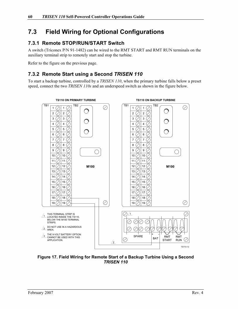
60 TRISEN 110 Self-Powered Controller Operations Guide
7.3 Field Wiring for Optional Configurations
7.3.1 Remote STOP/RUN/START Switch A switch (Triconex P/N 91-1482) can be wired to the RMT START and RMT RUN terminals on the auxiliary terminal strip to remotely start and stop the turbine.
Refer to the figure on the previous page.
7.3.2 Remote Start using a Second TRISEN 110 To start a backup turbine, controlled by a TRISEN 110, when the primary turbine falls below a preset speed, connect the two TRISEN 110s and an underspeed switch as shown in the figure below.
M100M100
19
18
17
16
15
14
13
12
11
10
9
8
7
6
5
4
3
2
1TB2TB1
19
18
17
16
15
14
13
12
11
10
9
8
7
6
5
4
3
2
1
19
18
17
16
15
14
13
12
11
10
9
8
7
6
5
4
3
2
1
19
18
17
16
15
14
13
12
11
10
9
8
7
6
5
4
3
2
1
SPAREBAT
+ -RMT
STARTRMTRUN
THIS TERMINAL STRIP ISLOCATED INSIDE THE TS110,BELOW THE M100 TERMINALSTRIPS.
11
2
2DO NOT USE IN A HAZARDOUSAREA.
3 THE 9-VOLT BATTERY OPTIONCANNOT BE USED WITH THISAPPLICATION.
TS110 ON PRIMARY TURBINE TS110 ON BACKUP TURBINE
TS110-12
TB2TB1
Figure 17. Field Wiring for Remote Start of a Backup Turbine Using a Second TRISEN 110
February 2007 Rev. 4
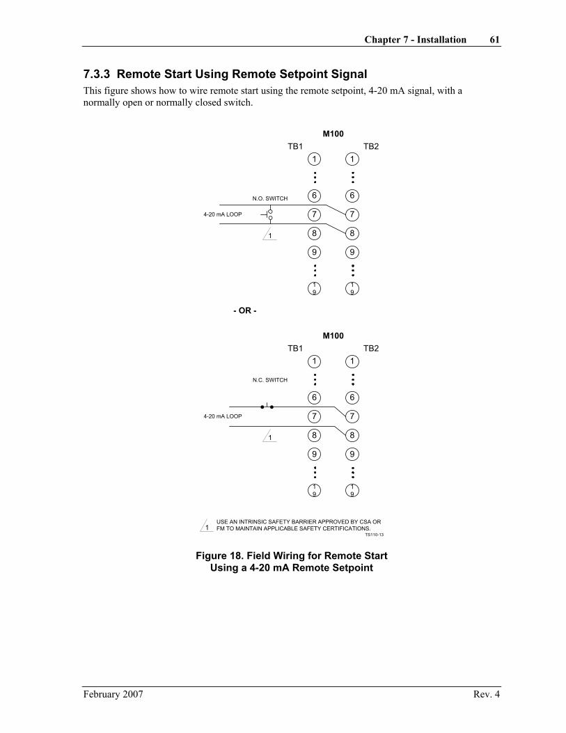
Chapter 7 - Installation 61
7.3.3 Remote Start Using Remote Setpoint Signal This figure shows how to wire remote start using the remote setpoint, 4-20 mA signal, with a normally open or normally closed switch.
1
6
8
9
7
19
1
6
8
9
7
19
TB1 TB2
N.O. SWITCH
4-20 mA LOOP
M100
1USE AN INTRINSIC SAFETY BARRIER APPROVED BY CSA ORFM TO MAINTAIN APPLICABLE SAFETY CERTIFICATIONS.
1
1
6
8
9
7
19
1
6
8
9
7
19
TB1 TB2
N.C. SWITCH
4-20 mA LOOP
M100
1
- OR -
TS110-13
Figure 18. Field Wiring for Remote Start Using a 4-20 mA Remote Setpoint
February 2007 Rev. 4

62 TRISEN 110 Self-Powered Controller Operations Guide
7.3.4 Overspeed Trip Relay An optional Solid State Relay (Triconex P/N 7015-0000) can be used to trip the machine in an overspeed condition by operating the dump solenoid, or by unlatching the trip lever. Refer to the figure below. For more information, refer to Section 8, Operations, of this manual.
2
3
1
5
6
4
8
9
7
11
12
10
14
15
13
16
18
19
17
2
3
1
5
6
4
8
9
7
11
12
10
14
15
13
16
18
19
17
TB1 TB2
1
M100
1
2
USE AN INTRINSIC SAFETYBARRIER APPROVED BY CSA ORFM TO MAINTAIN APPLICABLESAFETY CERTIFICATIONS.
JUMPER W9 MUST BEINSTALLED.
SOLID STATERELAY
(TRICONEXPN 7015-0000)
+ -
SOLENOID
AC LINE
1
TS110-14
Figure 19. Field Wiring for Overspeed Trip Relay
February 2007 Rev. 4

Chapter 7 - Installation 63
7.4 Pneumatic Installation
7.4.1 Piping Recommended supply piping for the I/P supply air is at least 3/8 inch. The recommended piping for the connection from the Governor I/P output to the final actuator is 1/4 inch. A 0-30 PSIG gauge should be installed on the governor I/P output to aid in troubleshooting and tuning. This connection should be kept as short as possible for the fastest response of the control valve. Though copper tubing is adequate, stainless steel is recommended.
7.4.2 Optional Pneumatic Speed Setpoint This is a 3-15 PSIG signal that can be used to remotely set the running speed of the governor when the optional Pneumatic Transducer (Triconex P/N 91-1455) is used. This line can be 1/4-inch tubing.
7.4.3 Final Actuator Two types of pneumatic actuators can be used with the TRISEN 110 controller.
• Triconex recommends a piston actuator with positioner, such as the Triconex 9907. Under most circumstances the piston actuator with positioner will give a quicker and more accurate response to the control output of the controller.
• The other type is a diaphragm actuator. If a diaphragm actuator is chosen, an air booster must be used.
Both types are described in more detail below.
February 2007 Rev. 4

64 TRISEN 110 Self-Powered Controller Operations Guide
Regardless of the type chosen the following guidelines should be followed:
• 1. Keep the tubing from the TRISEN 110 I/P output to the actuator as short as possible and use 1/4-inch tubing.
• 2. At all tubing connections remove any burrs or restrictions caused when cutting the tubing.
• 3. Do not use an excessively large actuator. A 25 square inch actuator such as the Triconex 9907 is normally sufficient for most applications. Stroking time is much slower for a larger actuator.
• 4. If linkage is needed, choose linkage ratios that keep the actuator travel at about 1/2 to 1 inch. Excessive stroke only increases stroking time.
• 5. If linkage is needed, use only high quality components in the linkage. Aircraft type rod-end bearings with grease fittings are recommended. Keep slop (lost motion) in the linkage to a minimum.
Refer to the figure below.
TS110CONTROLLER
STEAMTURBINE
LOADPUMP, FAN,
COMPRESSOR
PISTONACTUATOR
STEAM
HIGHOUTPUT
PICKUPS
COARSETOOTHGEAR
3-15 PSIG SIGNAL
OPTIONAL REMOTE SETPOINT
POSITIONER
1/4" SS TUBING
3/8" SS TUBING
GOVOUTPUT
MANOUTPUT
INCRTRISEN
CONTROL SIGNAL1/4" SS TUBING
FILTER
CLEANREGULATED 30 PSIGAIR
PLANT AIR
TS110-17
MANUALLOADINGSTATION
Figure 20. Pneumatic Installation, General Guidelines
February 2007 Rev. 4

Chapter 7 - Installation 65
7.4.3.1 Diaphragm Actuator with Air Booster
Two instrument air lines are required:
• One line provides the TRISEN 110 I/P and the air booster with clean, dry, regulated supply air. The supply pressure should be 20 - 25 psi. Stainless steel tubing, 3/8-in diameter, is recommended for the supply line.
• The second line supplies the control signal from the TRISEN 110 to the air booster. Stainless steel tubing, 1/4-in diameter, is recommended for the control signal.
TS110CONTROLLER
STEAMTURBINE
LOADPUMP, FAN,
COMPRESSOR
PNEUMATICDIAPHRAGMACTUATOR
STEAM
HIGHOUTPUT
PICKUPS
COARSETOOTHGEAR
3-15 PSIG SIGNAL
PROCESSSUPPLY AIR
OPTIONAL REMOTE SETPOINT
AIRBOOSTER
1/4" SS TUBING
3/8" SS TUBING
TS110-15
Figure 21. Pneumatic Installation, Diaphragm Actuator with Air Booster
TS110CONTROLLER
STEAMTURBINE
LOADPUMP, FAN,
COMPRESSOR
PISTONACTUATOR
STEAM
HIGHOUTPUT
PICKUPS
COARSETOOTHGEAR
3-15 PSIG SIGNAL
PROCESSSUPPLY AIR75-150 PSIG
OPTIONAL REMOTE SETPOINT
POSITIONER
1/4" SS TUBING
3/8" SS TUBING
PROCESSSUPPLY AIR
TS110-16
3/8" SS TUBING
Figure 22. Pneumatic Installation, Piston Actuator with Positioner
7.4.3.2 Piston Actuator with Positioner
Three instrument air lines are required:
• One line provides clean, dry, regulated supply air to the TRISEN 110 I/P. The supply pressure should be as indicated in the Specifications section. Triconex recommends 25 PSIG. Stainless steel tubing, 3/8-in diameter, is recommended for the supply line signal.
• The second line provides clean, dry, regulated supply air to the Pneumatic Actuator. The supply pressure should be between 80 and 150 PSIG. Triconex recommends 100 PSIG. Stainless steel tubing, 3/8-in diameter, is recommended for this supply line.
February 2007 Rev. 4

66 TRISEN 110 Self-Powered Controller Operations Guide
• The third line supplies the control signal from the TRISEN 110 to the actuator positioner. Stainless steel tubing, 1/4-in diameter, is recommended for this line.
7.5 Hydraulic Actuator Systems Installation Most medium to large turbines are usually already equipped with hydraulic servomotor type actuators that can be converted to pneumatic control. This is best done by spring selection in the bellows of the servomotor. Some turbine manufacturers can supply parts for this conversion. This type of installation provides a high level of performance and reliability with few moving parts and a minimum of maintenance.
Hydraulic systems that have mechanically-operated pilots are best handled by the attachment of a small pneumatic actuator and positioner on the hydraulic pilot with mechanical (restoring link) feedback for the output piston rod.
7.6 Magnetic Speed Pickups Installation The magnetic speed pickups must be mounted so that they sense the gear radially (the pickup point is toward the turbine shaft). Drill and tap the holes for the pickups. The point at which the pickups enter the housing or bracket must be flat to allow the lock nut to hold the pickup.
Gap both pickups at 0.016 inch. This gap allows for the lowest possible power-up speed for the controller. The best way to gap the pickups is by using a brass feeler gauge. However, if you cannot reach the gap with a gauge, the following procedure can be used:
• 1. Make sure that the crown of a gear tooth is directly under the hole for the pickup.
• 2. Screw the pickup into the hole until it touches the top of the gear tooth.
• 3. Back out the pickup 1/2 turn and set it with a lock nut.
• 4. Repeat steps 1 through 3 for the second pickup.
Ensure that the gear/bearing/shaft assembly turns as true as possible, with not more than 0.005 inch run-out.
February 2007 Rev. 4
Chapter 7 - Installation 67
7.7 Gear Installation for Speed Sensing The gear should be mounted on the main turbine shaft. Considerations for mounting the gear are:
• The magnetic speed pickups must sense the gear radially, so the gear must be mounted such that the pickups also can be mounted appropriately.
• The gear must not interfere with the lubrication system of the turbine bearings.
• Standard gears usually must be slipped onto the turbine shaft, which will have a bearing on the location.
Two options are available for mounting the gears which are provided with the TRISEN 110 control system:
• Heat Shrinking: With this method, the gear is drilled 0.002 inch smaller than the turbine shaft. The gear is then heated to 400°F and is slipped onto the shaft. When the gear cools, it will shrink onto the shaft and be held firmly in place.
CAUTION! The hole must be drilled exactly in the center of the gear so that the gear is concentric with the turbine shaft. This should be done only by a qualified machinist in a machine shop.
• Set Screws: Since the heat shrink method (using open flame) cannot be used in some
hazardous areas, a second method can be used to mount the gear on the turbine shaft. Drill a hole in the gear of a size that will ensure a forced fit on the shaft. Place the gear onto the shaft and use a drill to dimple the turbine shaft through the two set screw holes in the gear and install a set screw in each hole. Place another set screw behind the first to prevent the first set screw from backing out.
IF A SPECIAL GEAR IS NEEDED, SUCH AS A SPLIT GEAR, CONSULT THE FACTORY.
February 2007 Rev. 4

Chapter 8 - Operation
8.1 Startup Startup modes are as follows:
• Battery powered start
• Remote start
• Start from 4-20 mA
• Manual loading station start (available option)
8.1.1 Battery By-Pass Start By using a 9-volt battery, a preset current can be sent to the I/P converter; thus sending a pneumatic signal to the actuator and opening the control valve. The current is sent to the I/P converter by setting the STOP/RUN/START switch on the TRISEN 110 to the Start position. When the turbine reaches a speed sufficient to power the TRISEN 110, the governor will take control of the output to the I/P and take the turbine to the designated speed.
With steam to the control valve turned off, set the STOP/RUN/START switch to the Start position while monitoring a pressure gauge on the output of the TRISEN 110. Adjust R44 to achieve the desired pressure from the I/P. This pressure should be the lowest pressure at which the turbine will accelerate to a speed at which the TRISEN 110 will power-on.
WARNING! Extreme caution should be taken when starting an uncoupled or unloaded turbine with the battery start mode. The steam flow to the turbine should be limited by the throttle valve when dealing with an uncoupled or unloaded turbine.
8.1.2 4- 20-mA Start If a 4 to 20 mA current signal is used as a remote speed setpoint, the TRISEN 110 can be started by using some of this current to open the control valve, as with the battery start mode.
To use this feature, W4 must be installed and a 4 to 20 mA signal must be connected to TB2:7,8. With steam to the control valve turned off, set the STOP/RUN/START switch to the Start position while monitoring a pressure gauge on the output of the TRISEN 110. Adjust R44 to achieve the desired pressure from the I/P. This pressure should be the lowest pressure at which the turbine will accelerate to a speed at which the TRISEN 110 will power-on.
NOTE: When using the 4 to 20 mA start mode, a normally closed switch must be installed in the current loop to disrupt the current signal and reset the 4 to 20 mA start mode. The signal is locked out after the TRISEN 110 is started to keep the TRISEN 110 from trying to restart after an overspeed trip without operator intervention. Refer to paragraph 7.3.3.
WARNING! Extreme caution should be taken when starting an uncoupled or unloaded turbine with the battery start mode. The steam flow to the turbine should be limited by the throttle valve when dealing with an uncoupled or unloaded turbine.
February 2007 Rev. 4

70 TRISEN 110 Self-Powered Controller Operations Guide
8.1.3 Remote Start The TRISEN 110 can be started by applying a 5-volt signal capable of providing at least 4 mA to the BATT +/- terminals, and by placing a jumper on the remote start terminals which are located on the bottom terminal strip.
With steam to the control valve turned off, set the STOP/RUN/START switch to the RUN position while monitoring a pressure gauge on the output of the TRISEN 110. Apply the remote start signal. Adjust R44 to achieve the desired pressure from the I/P. This pressure should be the lowest pressure at which the turbine will accelerate to a speed at which the TRISEN 110 will power-on.
The remote start can be used in conjunction with the underspeed switch of a second TRISEN 110 to start a back-up turbine. The underspeed switch on the TRISEN 110 controlling the primary turbine should be set as described in the configuration section of this manual. When the primary turbine falls below the preset speed, a 5-volt signal will be sent to the second TRISEN 110 controlling the back-up turbine. This signal will be used to send a current signal to the I/P which will, in turn, send a pneumatic signal to the actuator to open the control valve. The second TRISEN 110 will now power on and start controlling the back-up turbine.
To use the remote start feature to start a back-up turbine also controlled by a TRISEN 110, connect the two TRISEN 110s as described in paragraph 7.3.1.
8.1.4 Manual Loading Station Start (Option) By using the optional Triconex 9913-T Manual Loading Station (refer to Appendix D), the governor output can be by-passed and the turbine accelerated by use of a pneumatic switch and regulator. The Triconex Manual Loading Station can offer several benefits: first, the turbine can be accelerated slowly and then the control can be switched to the governor; and there is no need for external batteries which can be unreliable after periods of non-use.
To start the turbine using a manual loading station, the pneumatic switch on the manual loading station is placed in manual output. Set the STOP/RUN/START switch on the TRISEN 110 to Run and place the speed setpoint potentiometer to 0.0. The output signal to the actuator is then slowly accelerated to slightly above minimum governor speed by using the regulator on the manual loading station.
As the turbine reaches a speed adequate to power the M100 board, the TRISEN 110 will output the maximum signal (normally 15 PSIG). As the speed of the turbine is accelerated past the minimum governor speed, the TRISEN 110 will slowly start ramping down its output. When the pressure from the TRISEN 110 is equal to the pressure from the regulator, the pneumatic switch is moved to governor output and the TRISEN 110 is now in control.
WARNING!
When the manual loading station is in manual mode, the turbine governor valve cannot respond to speed or load changes.
8.2 Tuning This section provides a recommended procedure for setting the GAIN (R117), INTEGRAL (R116), DERIVATIVE (R115), DROOP (R101), and REDUCED GAIN BAND (R102).
8.2.1 Gain and Integral Most installations will work acceptably with the settings at mid-position. To achieve optimum performance, the controller must be tuned under load. Observe the following procedure:
February 2007 Rev. 4
Chapter 8 - Operation 71
• 1. Place the GAIN potentiometer (R117) at 1/3 turn clockwise (CW).
• 2. Place the INTEGRAL potentiometer (R116) at 1/3 turn clockwise.
• 3. With the machine at controller speed and loaded normally, VERY SLOWLY turn the GAIN potentiometer clockwise until the machine becomes unstable. Then turn it back counterclockwise until the instability disappears.
NOTE: It is normal for the machine to speed up or slow down while adjusting the GAIN. For this reason, adjust VERY SLOWLY.
• 4. Turn the INTEGRAL potentiometer (R116) clockwise until the machine again becomes unstable. Then turn back counterclockwise until the instability disappears.
• 5. Repeat steps 3 and 4 to obtain best performance.
The final test of the turbine or engine is start-up. If the machine comes up to controller speed quickly and smoothly with no overshoot, then the tuning is adjusted correctly. If the speed overshoots and then slows down, the INTEGRAL is too fast or the GAIN is too slow.
8.2.2 Derivative In most applications DERIVATIVE (R116) will not be used and should be turned fully counterclockwise. Situations when DERIVATIVE might help performance are:
• If the load is mostly inertial.
• If the machine is required to add or shed load very quickly without excessive droop or overspeed.
The best way to implement DERIVATIVE is to adjust R116 clockwise and then simulate a machine load change. Keep repeating this procedure until the best response is obtained. If the machine becomes unstable at normal operating speed, turn DERIVATIVE counterclockwise until the instability disappears.
February 2007 Rev. 4

72 TRISEN 110 Self-Powered Controller Operations Guide
8.2.3 Reduced Gain Band Normally the REDUCED GAIN BAND (R102) will be adjusted fully counterclockwise. However, the REDUCED GAIN BAND (R102) can be very useful in the following applications:
• Diesel engines
• Steam turbines with an oscillating or a reciprocating load
• Steam turbine applications in which the machine is required to add or shed load very quickly without excessive droop or overspeed.
In all cases, adjust R116 as little as possible clockwise to achieve the desired results. The addition of too much REDUCED GAIN BAND will decrease the governor's response to small changes in speed. The figure below shows how the addition of REDUCED GAIN BAND affects controller performance.
REDUCED GAIN BANDADJUSTABLE 0-10%
REDUCED GAIN = 1/20OF NORMAL GAIN
0 + ERROR- ERROR
OU
TPU
T G
AIN
ERROR BETWEEN SETPOINT AND SPEED SIGNALTS110-2
Figure 23. Reduced Gain Band
8.2.4 Droop Normally the DROOP (R101) will be fully counterclockwise allowing the governor to run in isochronous mode. If the turbine is to be used in synchronous generator applications, DROOP will allow the machine to take load while staying at synchronous speed. Also if the machine is to be run with other machines on a shared load, DROOP will allow for inherent differences in the machines and keep one machine from hogging the load.
February 2007 Rev. 4
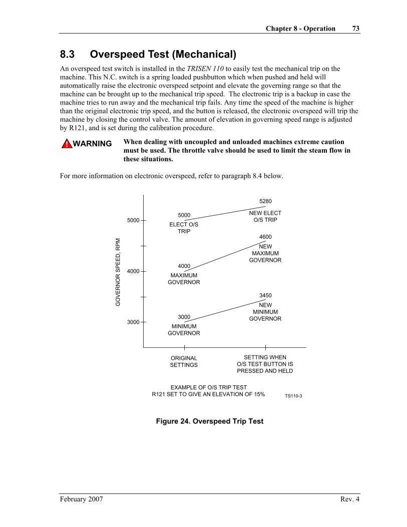
Chapter 8 - Operation 73
8.3 Overspeed Test (Mechanical) An overspeed test switch is installed in the TRISEN 110 to easily test the mechanical trip on the machine. This N.C. switch is a spring loaded pushbutton which when pushed and held will automatically raise the electronic overspeed setpoint and elevate the governing range so that the machine can be brought up to the mechanical trip speed. The electronic trip is a backup in case the machine tries to run away and the mechanical trip fails. Any time the speed of the machine is higher than the original electronic trip speed, and the button is released, the electronic overspeed will trip the machine by closing the control valve. The amount of elevation in governing speed range is adjusted by R121, and is set during the calibration procedure.
WARNING! When dealing with uncoupled and unloaded machines extreme caution must be used. The throttle valve should be used to limit the steam flow in these situations.
For more information on electronic overspeed, refer to paragraph 8.4 below.
3000
4000
5000
3000
3450
4000
4600
5000
5280
MINIMUMGOVERNOR
NEWMINIMUM
GOVERNOR
MAXIMUMGOVERNOR
NEWMAXIMUM
GOVERNOR
ELECT O/STRIP
NEW ELECTO/S TRIP
SETTING WHENO/S TEST BUTTON ISPRESSED AND HELD
ORIGINALSETTINGS
GO
VER
NO
R S
PEED
, RPM
EXAMPLE OF O/S TRIP TESTR121 SET TO GIVE AN ELEVATION OF 15% TS110-3
Figure 24. Overspeed Trip Test
February 2007 Rev. 4

74 TRISEN 110 Self-Powered Controller Operations Guide
8.4 Electronic Overspeed The electronic overspeed will cause the controller to remove all current to the I/P, thus closing the control valve when an overspeed condition is reached. The overspeed setpoint is configurable and can be set to any RPM the user wishes. The Configuration and Calibration section of this manual describes how to set the electronic overspeed setpoint. When the overspeed setpoint is reached, the controller will also trigger an SCR which can act as a switch for current from the 5 volts from the M100 terminal strip (TB2:12,13 with W9 installed) or externally supplied current from a DC power source. For specifications on the SCR refer to the Specification Section of this manual. The SCR can also be used with an optional Solid State Relay (Triconex P/N 7015-0000) to operate the dump solenoid or to unlatch the trip lever of the machine. The field wiring for this option is shown in the Installation section of this manual.
WARNING! The Electronic Overspeed is only meant as a backup to the machine's mechanical trip. The machine should always be equipped with a separate overspeed shutdown to protect against runaway in the unlikely event that the electronics, I/P, or the final actuator fails.
8.5 Underspeed Switch The underspeed switch was designed to provide power for a second TRISEN 110 on a backup machine when the speed of the primary machine falls below a set amount. The field wiring for this configuration is described in paragraph 7.3.1. The Configuration and Calibration section of this manual describes how to calibrate the underspeed switch.
The underspeed switch can also be used to sound an alarm. For information on the output of the underspeed switch refer to the Specification section of this manual.
February 2007 Rev. 4

Chapter 9 - Maintenance The TRISEN 110 requires no routine maintenance, except periodic inspections for loose covers and fittings, and mounting checks. The controller enclosure should be opened occasionally and the components checked to make sure they are tight, clean and dry.
If the M100 is removed from its housing, take electrostatic discharge precautions as described in the front of this manual.
February 2007 Rev. 4


Chapter 10 - Troubleshooting Symptom Cause Remedy
LED Does Not Flash Only one pickup installed. None. Pickup(s) bad or wiring problem. Check pickup(s) and wiring. LED connection. Check wiring, observe polarity. No Output to I/P Controller latched due to
overspeed trip. Reduce speed setpoint or increase overspeed trip setpoint, and turn STOP/RUN/START switch to STOP, then back to RUN.
Run switch open/not connected. Close switch, check wiring. Controller under-powered. Check for 5 V at TP2; if too low,
machine is running too slow or there's a problem with a pickup.
Jumper missing from remote run terminal at bottom.
Install jumper.
Will Not Control Speed After 600 RPM Is Reached
Pickup faulty or gapped too far. Check for signal; correct as needed.
I/P transducer. Repair as necessary. Final actuator. Repair as necessary. Circuit board. See preliminary test procedure. W6 on circuit board not
installed. Install W6 on circuit board.
Machine Runs At Maximum Output
Speed range jumper not installed. Install and cycle power.
Machine Speed Insensitive To Either Setpoint
Max output limit too low. Min output limit too high. Min gov speed too high. Max gov speed too low.
Perform preliminary test and calibrate min/max output settings.
Machine Will Not Come Up To Set Speed
Machine overloaded. Reduce load.
Final actuator. Readjust or repair as necessary. Steam supply restriction. Check the valves, etc. Leak in output air tubing. Repair air leak. Turbine mechanical overspeed
tripped. Reset trip.
Machine Overspeeds At Startup
Gain and reset incorrectly set. See tuning procedure.
Steam valve not closing with signal demand.
Readjust or repair steam valve as necessary.
Speed Droops Excessively While Taking Load
Gain and reset incorrectly set. See tuning procedure.
Steam supply restricted. Check the valves, etc.
February 2007 Rev. 4

78 TRISEN 110 Self-Powered Controller Operations Guide
Symptom Cause Remedy Machine Overspeeds When Load Is Removed
Gain and reset incorrectly set. See tuning procedure.
Steam valve not closing with signal demand.
Readjust or repair steam valve as necessary.
Negative 4 V at TP3 Not Present
No signal from pickup. Check pickup for signal; correct as necessary.
Machine Won't Start; Controller Valve Won't Open
START button; contact not closing.
Check with ohmmeter; replace if necessary.
STOP button; contact not opening.
Check with ohmmeter; replace if necessary.
Remote stop contact closed. Repair remote device or clear STOP condition.
Electric-to-pneumatic transducer. See test procedures. Final actuator. Circuit board. Machine Won't Start; Controller Valve Does Open
Manual trip not reset. Reset trip.
Steam or fuel supply blocked. Check supply valve(s). Machine Will Not Stop STOP button or contact. Check with ohmmeter; replace if
necessary. Circuit board. See test procedure. Local Or Remote Tach Doesn't Read, Or Reads Incorrectly
Tachometer adjustment. Adjust R59 on main board.
Tachometer. Replace tach. Both Local And Remote Tachs Don't Read, Or Read Incorrectly
Speed sensor. See test procedures.
Circuit board. Machine Will Not Slow Down As Local Speed Control Is Lowered
Remote speed set input too high. Lower remote setpoint; the TRISEN 110 will control to the highest speed.
Minimum speed dial on main board not correctly set.
Set dial for desired minimum governor speed.
Machine Will Not Slow Down As Remote Speed Set Signal Is Lowered
Local speed control set too high. Lower local speed control setting.
February 2007 Rev. 4

Chapter 10 - Troubleshooting 79
Symptom Cause Remedy Machine runs at max governor speed and will not respond to either setpoint
Local speed control. Test pot with ohmmeter and check connections; replace if necessary.
Remote speed set resistor, if used.
Check for open resistor with an ohmmeter.
Remote speed set transducer, if any.
Check for 1000 ohms across white and black wires.
Circuit board. See test procedures. Adjustable Speed Range Is Incorrect
Main board calibration error. See calibration section.
Machine Speed Cycles (Hunts)
Sticking, reduced gain band or linkage slop in the final actuator.
Repair actuator as necessary.
GAIN and RESET incorrectly set.
See paragraph 8.2 for tuning instructions.
Under or Overspeed Trips Do Not Function
Trips not correctly calibrated. See calibration section.
Trip solenoid. Check coil with ohmmeter; repair if necessary.
Trip relay. Replace the relay. This is a solid-state relay and should not be checked by conventional methods.
Circuit board. See test procedures. Digital Tachometer Does Not Read
No supply voltage from controller.
See test procedures.
Speed sensor. See test procedures. Digital tach defective. Replace tach.
February 2007 Rev. 4