triple-band printed dipole antenna with single-band … · · 2017-12-17progress in...
TRANSCRIPT

Progress In Electromagnetics Research B, Vol. 20, 225–244, 2010
TRIPLE-BAND PRINTED DIPOLE ANTENNA WITHSINGLE-BAND AMC-HIS
M. Abu, M. K. A. Rahim, O. Ayop, and F. Zubir
Radio Communication Engineering Department (RaCED)Universiti Teknologi Malaysia (UTM)81310 Skudai, Johor Bahru, Malaysia
Abstract—In this paper, the designed of triple-band printeddipole antennas are incorporated with single-band artificial magneticconductor (AMC). The single-band AMCs are designed to resonateat 0.92GHz, 2.45GHz and 5.8GHz using TLC-32 dielectric substrate.The four important parameters in AMC high impedance surface (HIS)design are also described in this paper. By simulating a unit cell ofthe AMC structure using a transient solver in Computer SimulationTechnology (CST) software, the characteristic of the AMC can becharacterized. The AMC condition is characterized by the frequencyor frequencies where the magnitude of the reflection coefficient is +1and its phase is 0. It has high surface impedance (Zs) and it reflectsthe external electromagnetic waves without the phase reversal. Thischaracteristic of AMC enables the printed dipole to work properlywhen the antenna with AMC ground plane (GP) is directly attachedto the metal object. The performances of the antenna with and withoutAMC structure as a ground plane to the antenna such as return loss,realized gain, radiation efficiency, radiation pattern and directivity arestudied. Reported results show that the performances of the antennaare improved. Hence, the designed dipole tag antenna can be used formetal object identifications when the AMC structure is introduced as aground to the antenna. The properties of the antenna are also remainedwell when the size of metal plate attached to them is increased.
1. INTRODUCTION
In recent years, there has been increasing interest in investigatingmetamaterial structures that exhibit novel electromagnetic propertiesnot found in nature. The metamaterial structures include the artificial
Corresponding author: M. Abu ([email protected]).

226 Abu et al.
magnetic conductor (AMC) which is known as perfect magneticconductor (PMC). It has high impedance surface exhibits a reflectivityof +1 oppose to a perfect electric conductor (PEC) which has areflectivity of −1 [1–4]. The AMC condition is characterized by thefrequency or frequencies where the phase of the reflection coefficient iszero degrees. The AMC structure has reflected wave in phase with theincident wave. Multi-band and W-band AMC structures were proposedin [5, 6] and the details about simulation of high impedance surfaceusing time-domain solver can be found in [7]. These high impedancestructures have also been shown to reduce the surface waves, to smooththe radiation patterns and to reduce the mutual coupling in arrayantenna [8].
The comparative study on various artificial magnetic conductorsfor low-profile antenna was done in [9]. They found that the mushroom-like electromagnetic band gap (EBG) has wider bandwidth than uni-planar compact EBG, Peano curve of order 1 and Hilbert curve of order2. While in [10], it introduces a probe fed patch antenna surroundedby high impedance surface structure to get more antennas’ directivity.In [11, 12], the slots on mushroom EBG structures [1, 2] are appliedto get the multiple band-gap. The characteristic of high impedancestructure, which is band gap, was analyzed in [13]. A transmission linemethod was used to study the band-gap of the HIS structure. Withabsent of vias, there are no band-gap appear at the specific frequencyrange. But, with the design of uni-planar compact EBG proposedin [8, 9, 14], the band-gap was appeared but the vias were replaced bya thin of conductor line.
In Radio Frequency Identification (RFID) system, the tag antennagain is the important parameter for the reading distance. The rangeis largest in the direction of maximum gain, which is fundamentallylimited by the size and radiation pattern of the antenna [15, 16].Various structures of dipole antenna are proposed for RFID andwireless Local Area Network (WLAN) applications [17–20]. Generally,the label-fabricated dipole tag antenna can not work on metallicsurface. To overcome this problem, two types of tag design for metallicobjects were proposed in [21]. They proposed printed inverted-Fantenna (PIFA) and patch antenna with electromagnetic band-gap.The effects of metallic plate size on UHF passive tag performancealso were studied in [22]. From the research done, they concludethat the performance of the tag antennas were still too dependenton the dimensions of the metallic plates close to them. As statedin [23], the tag performance mainly due to various kinds of platformmaterials can be prevented and the antenna gain also can be increasedwhen AMC is used a ground plane to the low-profile antenna. The

Progress In Electromagnetics Research B, Vol. 20, 2010 227
AMC structure was studied in [24] to make a low-profile passive radiofrequency identification (RFID) tag whose performance is tolerant tovarious platform materials such us lossy liquids and metallic objects.
In this paper, the triple-band printed dipole antennas proposedin [25] are applied. These antennas are constructed based on aprinted triple-band monopole antenna that was proposed in [26]. Thedeveloped antenna is then incorporated with single-band AMC-HISoperating at 0.92GHz, 2.45 GHz and 5.8 GHz. In order to verify theantenna with AMC-HIS ground plane (GP) can be used for metalobject identifications; the antenna with single-band AMC-HIS GPthen is incorporated with two different sizes of metal plates. Theperformances of the antenna at respective frequencies are studiedincluding the return loss, realized gain, radiation efficiency anddirectivity. So, this paper aims to introduce the triple band printeddipole tag antennas with high impedance surface structure for metalobject identifications.
This paper is structured as follows; Section 1 presents theliterature review of the paper. Section 2 will explain briefly thetriple band dipole antenna design, which is straight and meanderedstructures, followed by Section 3, where the design of single-bandAMC-HIS is described. Section 4 and Section 5 introduce triple-band dipole antennas with single-band AMC-HIS. In this chapter, theproperties of the antenna with and without AMC-HIS GP are discussedin detail. The properties of the antenna with AMC-HIS GP attachedto two different sizes of metal plates are also described in this section.Finally some conclusions are drawn in Section 6.
2. TRIPLE-BAND PRINTED DIPOLE ANTENNADESIGN
In this paper, the proposed antennas in [25] are applied in investigatingthe performances of the printed dipole antennas with and withoutsingle-band AMC-HIS structure as their ground plane. Then, it isfollowed by investigating the performances of the antenna with AMC-HIS GP attached directly to the metal plate.
The triple-band dipole was printed on one side of the RF-35substrate which has a dielectric constant, εr = 3.5, thickness, d =0.508mm and tangent loss, δ = 0.0019. In order to achieve a triple-band operation, the prime dipole antenna (operating at 0.92 GHz) wasconnected to the two branch elements, which act as an additionalresonator to resonate at 2.45GHz and 5.8 GHz. In the second design,the length of the prime dipole was meandered to reduce the antennasize. A 2.0 mm gap at the centre of the antenna is connected by a
228 Abu et al.
(a)
(b)
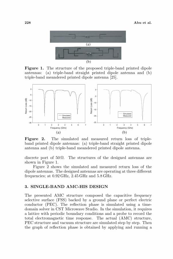
Figure 1. The structure of the proposed triple-band printed dipoleantennas: (a) triple-band straight printed dipole antenna and (b)triple-band meandered printed dipole antenna [25].
Measured
-30
-25
-20
-15
-10
-5
0
(a) (b)
0 1 32 4 5 6 7 0 1 32 4 5 6 7
-25
-20
-15
-10
-5
0
Re
turn
Lo
ss (
dB
)
Re
turn
Lo
ss (
dB
)
Frequency (GHz) Frequency (GHz)
Simulated
MeasuredSimulated
Figure 2. The simulated and measured return loss of triple-band printed dipole antennas: (a) triple-band straight printed dipoleantenna and (b) triple-band meandered printed dipole antenna.
discrete port of 50 Ω. The structures of the designed antennas areshown in Figure 1.
Figure 2 shows the simulated and measured return loss of thedipole antennas. The designed antennas are operating at three differentfrequencies; at 0.92GHz, 2.45GHz and 5.8 GHz.
3. SINGLE-BAND AMC-HIS DESIGN
The presented AMC structure composed the capacitive frequencyselective surface (FSS) backed by a ground plane or perfect electricconductor (PEC). The reflection phase is simulated using a time-domain solver in CST Microwave Studio. In the simulation, it requiresa lattice with periodic boundary conditions and a probe to record thetotal electromagnetic time response. The actual (AMC) structure,PEC structure and vacuum structure are simulated step by step. Thenthe graph of reflection phase is obtained by applying and running a

Progress In Electromagnetics Research B, Vol. 20, 2010 229
Frequency (GHz)
0.0 0.5 1.0 1.5 2.0
Frequency (GHz)
0 1 2 3 4 5
Reflection g
raph
(o)
-200
-150
-100
-50
0
50
100
150
200
p=16x16mm2
p=18x18mm2
p=20x20mm2
Reflection g
raph (
o)
-200
-150
-100
-50
0
50
100
150
200
g=0.25mm
g=1.25mm
g=2.25mm
Frequency (GHz)
2.0 2.2 2.4 2.6 2.8 3.0
Frequency (GHz)
1 2
Re
fle
ction g
raph
(o)
-200
-150
-100
-50
0
50
100
150
200
d=0.5mm
d=1.6mm
Re
fle
ctio
n g
rap
h (
o)
-200
-150
-100
-50
0
50
100
150
200
Er=4.4
Er=4.6
Er=4.8
(a) (b)
(c) (d)
3 4
Figure 3. The reflection graph when: (a) gap size, (b) patch size,(c) substrate permittivity and (d) substrate thickness of unit cell ofAMC-HIS is varied.
Table 1. Four important parameters in AMC-HIS design.
Resonant frequency Bandwidth
↑ Gap size (g) ↑ ↑↑ Patch size (p) ↓ ↓
↑ Substrate permittivity (Er) ↓ ↓↑ Substrate thickness (d) ↓ ↑
program in the VBA macro. Figure 3 illustrates the reflection phasegraph (in degrees) across frequency (in GHz). The graphs show theimportant parameters in AMC design. They are gap between a unit cellor lattice, patch size, substrate permittivity and substrate thickness.Table 1 summarizes the effect on resonant frequency and bandwidthof the AMC when these parameters are varied. The percentagebandwidth of the AMC is determined by:
BW =fu − fL
fc× 100% (1)

230 Abu et al.
where fu is the upper frequency such that the reflection phase equals−90, fL is the lower frequency where the reflection phase equals +90and fC is the centre frequency where the reflection phase equals 0.
Figure 3(a) plots the reflection graph of the AMC when the gapsize is varied from 0.25 mm to 2.25mm with all other values remainthe same. The effect of increasing the gap width is an increase inboth resonant frequency and bandwidth. While, Figure 3(b) showsthat as the patch size is increased both the resonant frequency andbandwidth are reduced. As can be seen in Figure 3(c), it shows thatas the substrate permittivity is increased both the resonant frequencyand bandwidth are also reduced. Next, Figure 3(d) shows that asthe substrate thickness is increased the resonant frequency is reducedand the bandwidth is increase. So, from the given reflection graph inFigure 3 and data in Table 1, it indicates that the substrate selectivityis important in order to achieve the design goal. At low frequencies, thethicker substrate is needed because the bandwidth is become narrower.The dimension of the AMC is larger if compared to the mushroomEBG that has a via at the center of the square patch. This is because;with via the unit cell size of the EBG at the specific frequency can bereduced and the band gap can be appeared.
A unit cell of the designed single-band AMC-HIS and its reflectiongraph are shown in Figure 4. The AMCs are designed to resonate at0.92GHz, 2.45 GHz and 5.8 GHz. The square patch AMC structuresare designed using TLC-32 dielectric substrate with permittivity of3.2 and thickness of 6.35mm. 0.92 GHz AMC-HIS has a patch size of67.5 × 67.5 mm2 with gap size of 1.25mm, 2.45 GHz AMC-HIS has apatch size of 18×18mm2 with gap size of 1 mm and 5.8 GHz AMC-HIShas a patch size of 4× 4mm2 with gap size of 1.75 mm respectively.
4. A TRIPLE-BAND STRAIGHT PRINTED DIPOLEANTENNA WITH SINGLE-BAND AMC-HIS
The designed single-band AMC-HIS then is incorporated with thetriple-band dipole antennas. The performances of the antenna arestudied such as return loss, realized gain, radiation efficiency, radiationpattern and directivity. In this paper, the performance of the antennaswith 2× 1 0.92 GHz AMC-HIS GP, 6× 1 2.45 GHz AMC-HIS GP and16× 1 5.8GHz AMC-HIS GP are investigated (see Figure 5). In orderto prove that the designed dipole tag antenna with AMC-HIS GP canbe used for metal object identification, the performances of the antennawith AMC-HIS GP attached to the metal plate are also investigated.So, this research begins with study the performance of the antennawith PEC GP. For an equivalent comparison, the PEC structure hassame dimension of the AMC structure (length × width × thickness).

Progress In Electromagnetics Research B, Vol. 20, 2010 231
(a) (b)
(c)
Frequency (GHz)
0.0 0.5 1.0 1.5 2.0
-200
-150
-100
-50
0
50
100
150
200
Frequency (GHz)
2.0 2.2 2.4 2.6 2.8 3.0
-200
-150
-100
-50
0
50
100
150
200
Frequency (GHz)
0 2 4 6 8 10
Re
fle
ctio
n g
rap
h (
)
o
-200
-150
-100
-50
0
50
100
150
200
Re
fle
ctio
n g
rap
h (
)
o
Re
fle
ctio
n g
rap
h (
)
o
Figure 4. Reflection graph of single-band AMC: (a) 0.92 GHz AMC-HIS, (b) 2.45GHz AMC-HIS and (c) 5.8GHz AMC-HIS.
Figure 5. The structure of triple-band dipole antenna with single-band AMC-HIS GP.
The graphs of calculated input return loss, radiation pattern,realized gain and radiation efficiency for triple-band straight printeddipole antenna, antenna with single-band AMC-HIS GP, antennawith PEC GP, antenna with single-band AMC-HIS GP attached to250mm × 250 mm and 500 mm × 500mm metal plates are shown inFigure 6 to Figure 8. The all obtained data are recorded in Table 2 toTable 4.

232 Abu et al.
Table 2. The performance of triple-band straight dipole antenna at0.92GHz.
Return
loss
(dB)
Realized
gain
(dB)
Radiation
Efficiency
(%)
Directivity
(dBi)
Triple-band straigh dipolet
antenna−23.57 1.91 99.46 1.95
Triple-band straight dipole
antenna with PEC GP−0.06 −25.24 5.71 5.91
Triple-band straight dipole
antenna with 0.92GHz
AMC-HIS GP
−10.16 5.20 96.01 5.82
Triple-band straight dipole
antenna with 0.92GHz
AMC-HIS GP and
250mm× 250mm metal plate
−5.64 5.39 93.36 5.66
Triple-band straight dipole
antenna with 0.92GHz
AMC-HIS GP and
500mm× 500mm metal plate
−5.65 4.89 93.04 5.21
Table 3. The performance of triple-band straight dipole antenna at2.45GHz.
Return
loss
(dB)
Realized
gain
(dB)
Radiation
Efficiency
(%)
Directivity
(dBi)
Triple-band straight dipole
antenna−10.47 2.00 91.44 2.80
Triple-band straight dipole
antenna with PEC GP−0.10 −21.10 8.90 5.66
Triple-band straight dipole
antenna with 2.45GHz
AMC-HIS GP
−14.70 7.30 92.83 7.78
Triple-band straight dipole
antenna with 2.45 GHz
AMC-HIS GP and
250mm× 250mm metal plate
−7.43 9.38 90.21 9.84
Triple-band straight dipole
antenna with 2.45GHz
AMC-HIS GP and
500mm× 500mm metal plate
−7.46 9.25 90.24 9.71
Progress In Electromagnetics Research B, Vol. 20, 2010 233
Frequency (GHz)
0.0 0.5 1.0 1.5 2.0
Re
turn
lo
ss (
dB
)
-30
-25
-20
-15
-10
-5
0
triple-band straight dipole antenna
antenna with 0.92 GHz AMC GP
antenna with PEC GP
antenna with 0.92 GHz AMC-HIS and 250x250mm2 metal plate
antenna with 0.92GHz AMC-HIS and 500x500mm2metal plate
0.0 0.2 0.4 0.6 0.8
0.0
0.2
0.4
0.6
0.8
0.00.20.40.60.8
0.0
0.2
0.4
0.6
0.8
0
30
60
90
120
150
180
210
240
27
300
330
triple-band straight dipole antenna
antenna with 0.92GHz AMC-HIS GP
antenna with PEC GP
antenna with 0.92GHz AMC-HIS and 250x250mm2 metal plate GP
antenna with 0.92GHz AMC-HIS and 500x500mm2 metal plate GP
(a) (b)
Frequency (GHz)
0.88 0.90 0.92 0.94 0.96 0.98 1.00 1.02
Realiz
ed g
ain
(dB
)
-30
-25
-20
-15
-10
-5
0
5
10
triple-band straight dipole antenna
antenna with 0.92GHz AMC-HIS GP
antenna PEC GP
antenna with 0.92GHz AMC-HIS and 250x250mm2 metal plate GP
antenna with 0.92GHz AMC-HIS and 500x500mm2 metal plate GP
Frequency (GHz)
0.88 0.90 0.92 0.94 0.96 0.98 1.00 1.02
Ra
dia
tio
n e
ffic
ien
cy
(%)
0
20
40
60
80
100
120
triple-band straight dipole antenna
antenna with 0.92GHz AMC-HIS GP
antenna with PEC GP
antenna with 0.92GHz AMC-HIS and 250x250mm2 metal plate GP
antenna with 0.92GHz AMC-HIS and 500x500mm2 metal plate GP
(c) (d)
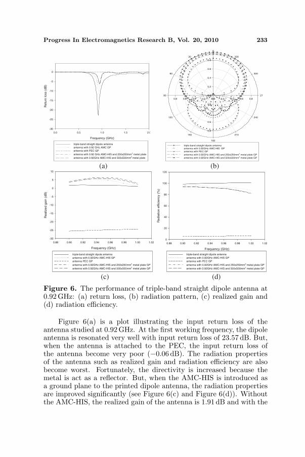
Figure 6. The performance of triple-band straight dipole antenna at0.92GHz: (a) return loss, (b) radiation pattern, (c) realized gain and(d) radiation efficiency.
Figure 6(a) is a plot illustrating the input return loss of theantenna studied at 0.92 GHz. At the first working frequency, the dipoleantenna is resonated very well with input return loss of 23.57 dB. But,when the antenna is attached to the PEC, the input return loss ofthe antenna become very poor (−0.06 dB). The radiation propertiesof the antenna such as realized gain and radiation efficiency are alsobecome worst. Fortunately, the directivity is increased because themetal is act as a reflector. But, when the AMC-HIS is introduced asa ground plane to the printed dipole antenna, the radiation propertiesare improved significantly (see Figure 6(c) and Figure 6(d)). Withoutthe AMC-HIS, the realized gain of the antenna is 1.91 dB and with the

234 Abu et al.
AMC-HIS it is increased to 5.20 dB. This is because; with AMC GP theradiation efficiency of the dipole antenna can be improved. When theantenna with AMC-HIS GP is attached to the 250mm×250mm metalplate, the performances of the antenna are remained well although themetal plate size is increased to 500 mm × 500 mm. As can be seen inFigure 6(b), the radiation pattern of the antenna is changed from omnito directional; hence it increase the directivity of the antenna. Theperformances of the antenna studied are almost similar at 2.45 GHzand 5.8 GHz.
Table 4. The performance of triple-band straight dipole antenna at5.8GHz.
Return
loss
(dB)
Realized
gain
(dB)
Radiation
Efficiency
(%)
Directivity
(dBi)
Triple-band straight dipole
antenna−14.73 3.00 98.45 3.22
Triple-band straight dipole
antenna with PEC GP−0.94 −5.13 42.41 5.71
Triple-band straight dipole
antenna with 5.8 GHz
AMC-HIS GP
−17.79 7.65 96.29 7.88
Triple-band straight dipole
antenna with 5.8 GHz
AMC-HIS GP and
250mm× 250mm metal plate
−22.69 8.13 95.97 8.33
Triple-band straight dipole
antenna with 5.8 GHz
AMC-HIS GP and
500mm× 500mm metal plate
−22.82 7.91 95.94 8.12
5. A TRIPLE-BAND MEANDERED PRINTED DIPOLEANTENNA WITH SINGLE-BAND AMC-HIS
In this section, the graphs of calculated input return loss, radiationpattern, realized gain and radiation efficiency for triple-bandmeandered printed dipole antenna, antenna with 2 × 1 0.92 GHz,5× 1 2.45 GHz, 10× 1 5.8GHz AMC-HIS GP, antenna with PEC GP,antenna with single-band AMC-HIS GP attached to 250 mm×250mmand 500 mm×500mm metal plates are shown in Figure 9 to Figure 11.Their performances also are summarized in Table 5 to Table 7.
Progress In Electromagnetics Research B, Vol. 20, 2010 235
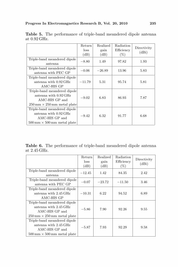
Table 5. The performance of triple-band meandered dipole antennaat 0.92 GHz.
Return
loss
(dB)
Realized
gain
(dB)
Radiation
Efficiency
(%)
Directivity
(dBi)
Triple-band meandered dipole
antenna−8.80 1.49 97.82 1.93
Triple-band meandered dipole
antenna with PEC GP−0.06 −26.89 13.96 5.83
Triple-band meandered dipole
antenna with 0.92GHz
AMC-HIS GP
−11.79 5.31 95.74 5.81
Triple-band meandered dipole
antenna with 0.92GHz
AMC-HIS GP and
250mm× 250mm metal plate
−9.02 6.83 86.93 7.87
Triple-band meandered dipole
antenna with 0.92GHz
AMC-HIS GP and
500mm× 500mm metal plate
−9.42 6.32 91.77 6.68
Table 6. The performance of triple-band meandered dipole antennaat 2.45 GHz.
Return
loss
(dB)
Realized
gain
(dB)
Radiation
Efficiency
(%)
Directivity
(dBi)
Triple-band meandered dipole
antenna−12.45 1.42 84.35 2.42
Triple-band meandered dipole
antenna with PEC GP−0.07 −23.72 −11.50 3.46
Triple-band meandered dipole
antenna with 2.45GHz
AMC-HIS GP
−10.31 6.22 94.52 6.89
Triple-band meandered dipole
antenna with 2.45GHz
AMC-HIS GP and
250mm× 250mm metal plate
−5.86 7.90 92.26 9.55
Triple-band meandered dipole
antenna with 2.45GHz
AMC-HIS GP and
500mm× 500mm metal plate
−5.87 7.93 92.29 9.58

236 Abu et al.
Frequency (GHz)
0.0 0.5 1.0 1.5 2.0 2.5 3.0
Re
turn
lo
ss
(dB
)
-30
-25
-20
-15
-10
-5
0
triple-band straight dipole antenna
antenna with 2.45GHz AMC-HIS GP
antenna with PEC GP
antenna with 2.45GHz AMC-HIS and 250x250mm2 metal plate GP
antenna with 2.45GHz AMC-HIS and 500x500mm2 metal plate GP
0.0 0.2 0.4 0.6 0.8
0.0
0.2
0.4
0.6
0.8
0.00.20.40.60.8
0.0
0.2
0.4
0.6
0.8
0
30
60
90
120
150
180
210
240
270
300
330
triple-band straight dipole antenna
antenna with 2.45GHz AMC-HIS GP
antenna with PEC GP
antenna with 2.45GHz AMC-HIS and 250x250mm2
metal plate GP
antenna with 2.45GHz AMC-HIS and 500x500mm2
metal plate GP
(a) (b)
Frequency (GHz)
2.38 2.40 2.42 2.44 2.46 2.48 2.50 2.52
Re
aliz
ed
Ga
in(d
B)
-25
-20
-15
-10
-5
0
5
10
15
triple-band straight dipole antenna
antenna with 2.45GHz AMC-HIS GP
antenna with PEC GP
antenna with 2.45GHz AMC-HIS and 250x250mm2 metal plate GP
antenna with 2.45GHz AMC-HIS and 500x500mm2 metal plate GP
Frequency (GHz)
2.38 2.40 2.42 2.44 2.46 2.48 2.50 2.52
Ra
dia
tio
n e
ffic
ien
cy
(%)
0
20
40
60
80
100
120
triple-band straight dipole antenna
antenna with 2.45GHz AMC-HIS GP
antenna with PEC GP
antenna with 2.45GHz AMC-HIS and 250x250mm2 metal plate GP
antenna with 2.45GHz AMCHIS and 500x500mm2
metal plate GP
(c) (d)
Figure 7. The performance of triple-band straight dipole antenna at2.45GHz: (a) return loss, (b) radiation pattern, (c) realized gain and(d) radiation efficiency.
Referring to Figure 9 and Table 5, at the preferred first workingfrequency, the antenna has return loss of 8.80 dB. When the antenna isincorporated with 2 × 1 0.92 GHz AMC-HIS, its return loss become11.79 dB and the most important here, the realized gain and thedirectivity of the antenna are increased significantly from 1.49 dB and1.93 dBi to 5.31 dB and 5.81 dBi. As data recorded in Table 5, when theantenna is attached to the PEC structure which is has same dimensionof the respective AMC structure, the return loss, realized gain andradiation efficiency of the antenna are very poor. The PEC structure

Progress In Electromagnetics Research B, Vol. 20, 2010 237
at the back of the antenna acts as a reflector so that it produces highdirectivity to the antenna. When the designed AMC is used as aground plane to the antenna, and then attached to the metal plate of250mm × 250 mm, the radiation properties such as realized gain andradiation efficiency of the antenna are remain high. The properties ofthe antenna are remained well when the antenna with AMC-HIS GPis attached to the bigger metal plate.
0.0 0.2 0.4 0.6 0.8
0.0
0.2
0.4
0.6
0.8
0.00.20.40.60.8
0.0
0.2
0.4
0.6
0.8
0
30
60
90
120
150
180
210
240
27
300
330
triple-band straight dipole antenna
antenna with 5.8GHz AMC-HIS GP
antenna with PEC GP
antenna with 5.8GHz AMC-HIS and 250x250mm2 metal plate GP
antenna with 5.8GHz AMC-HIS and 500x500mm2 metal plate GP
Frequency (GHz)
0 1 2 3 4 5 6
Retu
rn lo
ss (
dB
)
-50
-40
-30
-20
-10
0
triple-band straight dipole antenna
antenna with 5.8GHz AMC-HIS GP
antenna with PEC GP
antenna with 5.8GHz AMC-HIS and 250x250mm2 metal plate GP
antenna with 5.8GHz AMC-HIS and 500x500mm2 metal plate GP
(a) (b)
Frequency (GHz)
5.65 5.70 5.75 5.80 5.85 5.90 5.95
Realiz
ed G
ain
(dB
)
-8
-6
-4
-2
0
2
4
6
8
10
triple-band straight dipole antenna
antenna with 5.8GHz AMC-HIS GP
antenna with PEC GP
antenna with 5.8GHz AMC-HIS and 250x250mm2
metal plate GP
antenna with 5.8GHz AMC-HIS and 500x500mm2
metal plate GP
Frequency (GHz)
5.65 5.70 5.75 5.80 5.85 5.90 5.95
Ra
dia
tio
n E
ffic
iency (
%)
30
40
50
60
70
80
90
100
110
triple-band straight dipole antenna
antenna with 5.8GHz AMC-HIS GP
antenna with PEC GP
antenna with 5.8GHz AMC-HIS and 250x250mm2 metal plate GP
antenna with 5.8GHz AMC-HIS and 500x500mm2 metal plate GP
(c) (d)
Figure 8. The performance of triple-band straight dipole antenna at5.8GHz: (a) return loss, (b) radiation pattern, (c) realized gain and(d) radiation efficiency.

238 Abu et al.
Frequency (GHz)
0.0 0.5 1.0 1.5 2.0
Retu
rn loss (
dB
)
-30
-25
-20
-15
-10
-5
0
triple-band meandered dipole antenna
antenna with 0.92GHz AMC-HIS GP
antenna with PEC GP
antenna with 0.92GHz AMC-HIS and 250x250mm2 metal plate GP
antenna with 0.92GHz AMC-HIS and 500x500mm2 metal plate GP
0.0 0.2 0.4 0.6 0.8
0.0
0.2
0.4
0.6
0.8
0.00.20.40.60.8
0.0
0.2
0.4
0.6
0.8
0
30
60
90
120
150
180
210
240
27
300
330
triple-band meandered dipole antenna
antenna with 0.92GHz AMC-HIS GP
antenna with PEC GP
antenna with 0.92GHz AMC-HIS and 250x250mm2
metal plate GP
antenna with 0.92GHz AMC-HIS and 500x500xmm2 metal plate GP
(a) (b)
Frequency (GHz)
0.88 0.90 0.92 0.94 0.96 0.98 1.00 1.02
Re
aliz
ed
ga
in (
dB
)
-30
-25
-20
-15
-10
-5
0
5
10
triple-band meandered dipole antenna
antenna with 0.92GHz AMC-HIS GP
antenna with PEC GP
antenna with 0.92 GHz AMC-HIS and 250x250mm2
metal plate GP
antenna with 0.92GHz AMC-HIS and 500x500mm2 metal plate GP
Fequency (GHz)
0.88 0.90 0.92 0.94 0.96 0.98 1.00 1.02
Radia
tion E
ffic
iency (
%)
0
20
40
60
80
100
120
triple-band meandered dipole antenna
antenna with 0.92GHz AMC-HIS GP
antenna with PEC GP
antenna with 0.92GHz AMC-HIS and 250x250mm2 metal plate GP
antenna with 0.92GHz AMC-HIS and 500x500mm2 metal plate GP
(c) (d)
Figure 9. The performance of triple-band meandered dipole antennaat 0.92 GHz: (a) return loss, (b) radiation pattern, (c) realized gainand (d) radiation efficiency.
From Figure 9(b), it clearly shows that the radiation pattern of thedipole antenna are become directional when the antenna is attached tothe respective AMC and the directivity went higher when the antennawith AMC-HIS GP is attached to the metal plate. The property of theAMC which is the reflected wave is in phase with the incident waveenhances the radiation efficiency and gives in high gain to the antenna.From the data obtained, it shows that the radiation efficiency is high, so

Progress In Electromagnetics Research B, Vol. 20, 2010 239
it produces high realized gain. The gain is increased up to 256% whenthe antenna is placed just above the 2 × 1 0.92GHz AMC structure.This scenario or trend is showing almost similar at the middle andupper frequencies.
Frequency (GHz)
0.0 0.5 1.0 1.5 2.0 2.5 3.0 3.5
Re
turn
Lo
ss (
dB
)
-20
-15
-10
-5
0
5
triple-band meandered dipole antenna
antenna with 2.45GHz AMC-HIS GP
antenna with PEC GP
antenna with 2.45GHz AMC-HIS and 250x250mm2 metal plate GP
antenna with 2.45GHz AMC-HIS and 500x500mm2metal plate GP
0.0 0.2 0.4 0.6 0.8
0.0
0.2
0.4
0.6
0.8
0.00.20.40.60.8
0.0
0.2
0.4
0.6
0.8
30
60
90
120
150
180
210
240
27
300
330
triple-band meandered dipole antenna
antenna with 2.45GHz AMC_HIS GP
antenna with PEC GP
antenna with 2.45GHz AMC-HIS and 250x250mm2 metal plate GP
antenna with 2.45GHz AMC-HIS and 500x500mm2 metal plate GP
Frequency (GHz)
2.38 2.40 2.42 2.44 2.46 2.48 2.50 2.52
Realiz
ed G
ain
(dB
)
-30
-25
-20
-15
-10
-5
0
5
10
triple-band meandered dipole antenna
antenna with 2.45GHz AMC-HIS GP
antenna with PEC GP
antenna with 2.45GHz AMC and 250x250mm2 metal plate GP
antenna with 2.45GHz AMC-HIS and 500x500mm2 metal plate GP
Frequency (GHz)
2.38 2.40 2.42 2.44 2.46 2.48 2.50 2.52
Ra
dia
tion
Effic
ien
cy
(%)
0
20
40
60
80
100
120
triple-band meandered dipole antenna
antenna with 2.45GHz AMC-HIS GP
antenna with PEC GP
antenna with 2.45GHz AMC-HIS and 250x250mm2metal plate GP
antenna with 2.45GHz AMC-HIS and 500x500mm2 metal GP
(c) (d)
(a) (b)
0
Figure 10. The performance of triple-band meandered dipole antennaat 2.45 GHz: (a) return loss, (b) radiation pattern, (c) realized gain and(d) radiation efficiency.

240 Abu et al.
Table 7. The performance of triple-band meandered dipole antennaat 5.8 GHz.
Return
loss
(dB)
Realized
gain
(dB)
Radiation
Efficiency
(%)
Directivity
(dBi)
Triple-band meandered dipole
antenna−13.70 3.82 99.18 3.87
Triple-band meandered dipole
antenna with PEC GP−0.50 −5.62 42.68 7.75
Triple-band meandered dipole
antenna with 5.8 GHz
AMC-HIS GP
−13.91 7.24 96.75 7.39
Triple-band meandered dipole
antenna with 5.8GHz
AMC-HIS GP and
250mm× 250mm metal plate
−9.43 9.93 95.99 10.11
Triple-band meandered dipole
antenna with 5.8 GHz
AMC-HIS GP and
500mm× 500mm metal plate
−9.63 8.28 96.05 8.96
Frequency (GHz)
0 2 4 6
Retu
rn loss
(dB
)
-30
-25
-20
-15
-10
-5
0
5
triple-band meandered dipole antenna
antenna with 5.8GHz AMC-HIS GP
antenna with PEC GP
antenna with 5.8GHz AMC-HIS and 250x250mm2 metal plate GP
antenna with 5.8GHz AMC-HIS and 500x500mm2 metal plate GP
0.0 0.2 0.4 0.6 0.8
0.0
0.2
0.4
0.6
0.8
0.00.20.40.60.8
0.0
0.2
0.4
0.6
0.8
0
30
60
90
120
150
180
210
240
27
300
330
triple-band meandered dipole antenna
antenna with 5.8GHz AMC-HIS GP
antenna with PEC GP
antenna with 5.8GHz AMC-HIS and 250x250mm2 metal plate GP
antenna with 5.8GHz AMC-HIS and 500x500mm2 metal plate GP
(a) (b)

Progress In Electromagnetics Research B, Vol. 20, 2010 241
Frequency (GHz)
5.65 5.70 5.75 5.80 5.85 5.90 5.95
Re
aliz
ed
gain
(dB
)
-8
-6
-4
-2
0
2
4
6
8
10
12
triple-band meandered dipole antenna
antenna with 5.8GHz AMC-HIS GP
antenna with PEC GP
antenna with 5.8GHz AMC-HIS and 250x250mm2
metal plate GP
antenna with 5.8GHz AMC-HIS and 500x500mm2metal plate GP
Frequency (GHz)
5.65 5.70 5.75 5.80 5.85 5.90 5.95
Rad
iatio
n e
ffic
ien
cy
(%)
20
40
60
80
100
120
triple-band meandered dipole antenna
antenna with 5.8GHz AMC-HIS GP
antenna with PEC GP
antenna with 5.8GHz AMC-HIS and 250x250mm2 metal plate GP
antenna with 5.8GHz AMC-HIS and 500x500mm2 metal plate GP
(c) (d)
Figure 11. The performance of triple-band meandered dipole antennaat 5.8 GHz: (a) return loss, (b) radiation pattern, (c) realized gain and(d) radiation efficiency.
6. CONCLUSION
The performances of triple-band straight and meandered printed dipoleantenna with and without single-band 0.92GHz, 2.45 GHz and 5.8 GHzAMC-HIS ground plane have been analyzed in this paper. By usingthe AMC structure as a ground plane to the antenna, the radiationproperties of the antennas are improved. The reported results showthat, the realized gain, radiation efficiency and directivity are increasedsignificantly. In this paper also, the performance of the antenna withAMC-HIS ground plane attached to the metal plate has been studiedand their performances are remaining unchanged when the metal platesize is increased. In conclusion, it shows that the designed triple-banddipole tag antennas with single-band AMC-HIS can be used for metalobject identifications and it can be applied at UHF and microwavefrequency RFID frequency range.
7. FUTURE WORK
For future work, the proposed triple-band printed dipole antennas willbe integrated with the triple-band AMC-HIS (0.92GHz, 2.45GHz and5.8GHz). Measurement of the fabricated triple-band printed dipoleantenna with triple-band AMC-HIS must be carried out in order toverify the designs.

242 Abu et al.
REFERENCES
1. Sievenpiper, D., L. Zhang, R. F. J. Broas, N. G. Alexopolous, andE. Yablonovitch, “High-impedance electromagnetic surfaces witha forbidden frequency band,” IEEE Trans. Microwave TheoryTech., Vol. 47, 2059–2074, 1999.
2. Sievenpiper, D. F., “High-impedance electromagnetic surfaces,”Ph.D. Thesis, University of California at Los Angeles, 1999.
3. Poilasne, G., “Antennas on high impedance ground planes:On the importance of the antenna isolation,” Progress InElectromagnetics Research, PIER 41, 237–255, 2003.
4. Rea, S. P., D. Linton, E. Orr, and J. McConnell, “Broadbandhigh impedance surface design for aircraft HIRF protection,” IEEProceeding, Microwave Antennas Propagation, Vol. 153, No. 4,August 2006.
5. Kern, D. J., D. H. Werner, A. Monorchio, L. Lanuzza, andM. J. Wilhelm, “The design synthesis of multiband aritifialmagnetic conductors using high impedance frequency selectivesurfaces,” IEEE Transactions on Antennas and Propagation,Vol. 53, No. 1, 8–17, 2005.
6. Islam, S., J. Stiens, G. Poesen, I. Jaeger, G. Koers, andR. Vounckx, “W-band millimeter wave artificial magneticconductor realization by grounded frequency selective surface,”Proceedings Symposium IEEE/LEOS Benelux Chapter, 183–186,Brussels, 2007.
7. Zhou, X., F. Hirtenfelder, Z. Yu, and M. Zhang, “Fast simulationof high impedance surface using time domain solver,” 2004 4thInternational Conference on Microwave and Millimeter WaveTechnology Proceedings, 731–734, 2004.
8. Yang, F. and R. Samii, Electromagnetic Band Gap Structures inAntenna Engineering, 156–201, Cambridge University Press, 2009.
9. Sohn, J. R., K. Y. Kim, and H.-S. Tae, “Comparative study onvarious artificial magnetic conductors for low-profile antenna,”Progress In Electromagnetics Research, PIER 61, 27–37, 2006.
10. Ourir, A. and A. de Lustrac, “Artificial magnetic conductor highimpedance surface for compact directive antennas,” Progress InElectromagnetics Research Symposium 2005, 23–26, 2005.
11. Xie, H.-H., Y.-C. Jiao, K. Song, and Zhang, “A novel multi-bandelectromagnetic bandgap structure,” Progress In ElectromagneticsResearch Letters, Vol. 9, 67–74, 2009.
12. Ayop, O., M. K. A. Rahim, M. Abu, and T. Masri, “Slottedpatch dual band electromagnetic band gap structure design,”
Progress In Electromagnetics Research B, Vol. 20, 2010 243
3rd European Conference on Antennas and Propagation (EuCAP2009), Berlin, Germany, March 23–27, 2009.
13. Abu, M., M. K. A. Rahim, M. K. Suaidi, I. M. Ibrahim,and N. M. Nor, “Dual-band artificial magnetic conductor(AMC),” Proceedings of 2009 IEEE International Conferenceon Antennas, Propagation and Systems (INAS 2009), Johor,Malaysia, December 3–5, 2009.
14. Gu, Y.-Y., W.-X. Zhang, Z.-C. Ge, and Z.-G. Liu, “Researchon reflection phase characterizations of artificial magneticconductors,” 2005 Antennas and Propagation and MicrowaveConference, APMC, 2005.
15. Lehpamer, H., RFID Design Principles, Artech House, 2008.16. Chen, Z. N., Antenna for Portable Devices, 71–72, John Wiley &
Sons, 2007.17. Li, X., L. Yang, S.-X. Gong, Y.-J Yang, and J.-F. Liu, “A
compact folded printed dipole antenna for UHF reader,” ProgressIn Electromagnetics Research Letters, Vol. 6, 47–54, 2009.
18. Loo, C.-H., K. Elmahgoub, F. Yang, A. Elsherbeni, D. Kajfez,A. Kishk, and T. Elsherbeni, “Chip impedance matching forUHF RFID tag antenna design,” Progress In ElectromagneticsResearch, PIER 81, 359–370, 2008.
19. Chang, K., H. Kim, K. S. Hwang, I. J. Yoon, and Y. J. Yoon,“A triple-band printed dipole antenna using parasitic elements,”Microwave and Optical Technology Letters, Vol. 47, 221–223, 2005.
20. Wu, Y.-J., B.-H. Sun, J.-F. Li, and Q.-Z. Liu, “Triple-bandomni-directional antenna for WLAN application,” Progress InElectromagnetics Research, PIER 76, 477–484, 2007.
21. Ukkonen, L., L. Sydanheimo, and M. Kivikoski, “Patch antennawith EBG ground plane and two-layer substrate for passive RFIDof metallic objects,” Proc 2004 IEEE AP-S, Vol. 1, 93–96, 2004.
22. Ukkonen, L., L. Sydanheimo, and M. Kivikoski, “Effects ofmetallic plate size on the performance of microstrip patch-typetag antennas for passive RFID,” IEEE Antennas and WirelessPropagation Letters, Vol. 4, 2005.
23. Mateos, R. M., J. M. Gonzalez, C. Craeye, and J. Romeu,“Backscattering measurement from a RFID tag based on artificialmagnetic conductors,” 2nd European Conference on Antennas andPropagation (EuCAP 2007), Edinburgh, UK, November 11–16,2007.
24. Kim, D. and J. Yeo, “Low-profile RFID tag antenna usingcompact AMC substrate for metallic objects,” IEEE Antennas

244 Abu et al.
and Wireless Propagation Letters, Vol. 7, 718–720, 2008.25. Abu, M. and M. K. A. Rahim, “Triple-band printed dipole tag
antenna for RFID,” Progress In Electromagnetics Research C,Vol. 9, 145–153, 2009.
26. John, M. and M. J. Ammann, “Integrated antennafor multiband multi-national wireless combined withGSM1800/PCS1900/IMT2000+extension,” Microwave andOptical Technology Letters, Vol. 48, No. 3, 613–615, March 2006.