trion technology oracle operator ...images.wikia.com/nanolab/ru/images/6/60/manual-oraiii...samples...
TRANSCRIPT
2131 Sunnydale Blvd, Clearwater, FL 33765 · (727)461-1888 · Fax (727)461-1858
[email protected] · www.triontech.com
TRION TECHNOLOGY
ORACLE OPERATOR & MAINTENANCE MANUAL
VOLUME 1

2
TABLE OF CONTENTS
I) Warranty & Service .......................................................…………....….... 4 II) System Warning .....................................................................……….... 6 III) System Description ...................................................................………. 8 General ………....................................................................……….. 8 System Specifications ………………………………………………………………. 9 Equipment ................................................................................... 10 CVT (Central Vacuum Transport) …………………………………….. 10 Equipment Console ………………………………………………………… 10
Emergency Shut-Off ..........................................….............. 11 Process Module ……………………………………………………………… 11
RF Generators.................................................................... 13 Automatic RF Tuning – Etch Chambers ................................ 14
Automatic RF Tuning – Deposition Chambers ..….................. 15 Manual Tuning – High Frequency .......................….............. 16 Process Module Controller …..............................…............... 17 Vacuum System ................................................................. 17 Recirculating Chiller ........................................................... 17 Laser Endpoint Detection System ……………………………………. 18 IV) Safety Specifications ................................................................………. 19 Safety Standards .......................................................................... 19 Lock Out/Tag Out ..............................................................…........ 19 Emergency Off System ................................................................. 20 Interlocks ..................................................................................… 21 Equipment Electrical Design .......................................................... 22 Chemical Use ............................................................................... 22 Emissions ..................................................................................… 23 Labeling ....................................................................................... 23 Earthquake Protection ................................................................… 23 Mechanical Safety ......................................................................... 23 “What If” Hazard Analysis ............................................................. 24 V) Installation .......................................................................................... 25 Inspection ..................................................................................... 25 Facilities ........................................................................................ 25 Installation Procedure .................................................................... 26 VI) System Operation ………………................................................................ 29 System Start Up .............….............................................................. 29

3
Logging Onto The System ................................................................ 31 Loading a Recipe.............................................................................. 32 Loading a Wafer …………………........................................................... 35 Setting Up the Laser …………………………………………………………………… 37 Running a Process - Automatically..................................................... 38 Reviewing Laser Data …………………………………………………………………. 43 Unloading a Wafer........................................................................... 44 Stand By Mode ………....................................................................... 45 VII) Typical Process Conditions ................................................................... 46 VIII) System Maintenance ........................................................................... 50 IX) Appendix A ………………………………………………………………………………………. 66 System diagrams, schematics and parts lists
© 2006 Trion Technology, Inc. All rights reserved. This manual may not be copied, in full or in part, without the express written approval of the copyright holder.

4
I) WARRANTY & SERVICE INFORMATION
The TRION system is guaranteed to be free of defects in workmanship and components. This warranty covers labor and parts for a period of one year, unless an extended warranty has been purchased. The exclusive remedy for any breach or violation of the warranty is as follows: TRION TECHNOLOGY F.O.B CLEARWATER, FLORIDA will furnish without charge, repairs to or replacement of the parts or equipment which proved defective in material or workmanship. No claim may be made for any incidental or consequential damages. For defective equipment returns to Trion, the customer will pay shipping charges. Repaired or replaced equipment will be shipped back the customer at Trion’s expense. TRION TECHNOLOGY will inspect the equipment and decide upon such repairs or replacement as necessary. The customer will be notified of any charges incurred that are not covered by this warranty prior to accomplishment of any such repairs. Any customer modification of this equipment, or any repairs, undertaken without the prior consent of TRION TECHNOLOGY will render this warranty void. This warranty is expressly in lieu of all other warranties, express or implied, including any implied warranty of merchantability or fitness for a particular purpose unless otherwise agreed in writing signed by TRION TECHNOLOGY.

5
NOTIFICATION OF EQUIPMENT PROBLEMS: If the system has a failure or other equipment problems you must notify TRION TECHNOLOGY immediately in writing by either FAX to (727) 447-1581 or e-mail at [email protected] attention: Service Coordinator. In addition please call the Service Department at (727) 447-1110 to schedule a service trip. Phone help is always provided free of charge. However, if the system is out of warranty a purchase order number will be required before a service trip is scheduled. RETURN OF EQUIPMENT: If an instrument is to be returned to TRION for service or for any reason, the following procedure should be followed:
1. Call the TRION TECHNOLOGY Service Department at (727) 447-1110 for a return authorization number (RMA). You may also e-mail TRION at [email protected] with any service related questions. If the unit is received without this number on the outside of the box it will be rejected by the Service Department.
2. Repack the instrument in the original shipping container. If this is no longer available, take
special precautions to avoid damage to any fragile components. TRION will not be responsible for any damages incurred during shipment from customer to TRION. A shipping container may be purchased from TRION TECHNOLOGY for a nominal charge.
3. If the instrument is still under warranty, the only charges will be shipping costs. If the
instrument is out of warranty, a purchase order will be required and you will be billed for all parts and service.
If you have any questions, do not hesitate to contact TRION Customer Service Department.

6
II) SYSTEM WARNING
SAFE OPERATING PROCEDURES AND PROPER USE OF THE EQUIPMENT ARE THE RESPONSIBILITY OF THE USER OF THIS SYSTEM. Trion Technology provides information on its products and its associated hazards, but assumes no responsibility for the after sale operation and safety practices. ALL PERSONNEL WHO WORK WITH OR ARE EXPOSED TO THIS EQUIPMENT MUST TAKE PRECAUTIONS TO PROTECT THEMSELVES AGAINST POSSIBLE SERIOUS AND/OR FATAL BODILY INJURY. DO NOT BE CARELESS AROUND THIS EQUIPMENT. The following hazards are present on this system. Warning labels are affixed to the appropriate locations on the system to notify the user of potential danger. HAZARD LOCATION
HAZARDOUS VOLTAGE Contact may cause electric shock or burn. Turn off and lock out system before servicing.
CHEMICAL HAZARD May cause skin/eye irritation. Wear gloves and eye protection while servicing.
Console ACD module. Process Chamber ACD module. Pump Contactor NEMA box. Inside RF generators. Inside chambers, at chuck.
Inside the chambers. Inside the gas cabinets. Inside the pumps.
FLAMMABLE MATERIAL Contents may burn if exposed to flame source. Keep spark or flame sources from container.
Gas Cabinet.
NON-IONIZING RADITION Contact may cause electric shock or burn. Turn off and lock out system before servicing.
Inside chambers with RF on. Inside RF generators with RF on.

7
*** RF WARNING ***
This machine uses RF frequency power. Care should be taken in its use. DO NOT operate this machine with any RF component enclosures open. These components should be service by trained personnel only. The frequency and power levels of the RF generators are as follows: Advanced Energy RFG 3001 1500 Watts maximum power @ 13.56Mhz Advanced Energy RFX 600A 600 Watts maximum power @ 13.56Mhz Seren L300 300 Watts maximum power @ 100 kHz
Inside chambers on chuck. Heater assembly on PECVD.
HOT SURFACE Contact may cause burn. Turn off and lock out before servicing.
8
III) SYSTEM DESCRIPTION
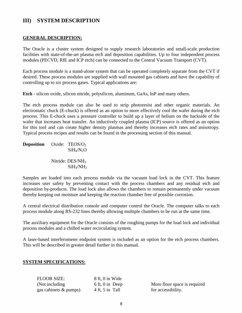
GENERAL DESCRIPTION: The Oracle is a cluster system designed to supply research laboratories and small-scale production facilities with state-of-the-art plasma etch and deposition capabilities. Up to four independent process modules (PECVD, RIE and ICP etch) can be connected to the Central Vacuum Transport (CVT). Each process module is a stand-alone system that can be operated completely separate from the CVT if desired. These process modules are supplied with wall mounted gas cabinets and have the capability of controlling up to six process gases. Typical applications are: Etch - silicon oxide, silicon nitride, polysilicon, aluminum, GaAs, InP and many others. The etch process module can also be used to strip photoresist and other organic materials. An electrostatic chuck (E-chuck) is offered as an option to more effectively cool the wafer during the etch process. This E-chuck uses a pressure controller to build up a layer of helium on the backside of the wafer that increases heat transfer. An inductively coupled plasma (ICP) source is offered as an option for this tool and can create higher density plasmas and thereby increases etch rates and anisotropy. Typical process recipes and results can be found in the processing section of this manual. Deposition Oxide: TEOS/O2 SiH4/N2O Nitride: DES/NH3 SiH4/NH3 Samples are loaded into each process module via the vacuum load lock in the CVT. This feature increases user safety by preventing contact with the process chambers and any residual etch and deposition by-products. The load lock also allows the chambers to remain permanently under vacuum thereby keeping out moisture and keeping the reaction chamber free of possible corrosion. A central electrical distribution console and computer control the Oracle. The computer talks to each process module along RS-232 lines thereby allowing multiple chambers to be run at the same time. The auxiliary equipment for the Oracle consists of the roughing pumps for the load lock and individual process modules and a chilled water recirculating system. A laser-based interferometer endpoint system is included as an option for the etch process chambers. This will be described in greater detail further in this manual.
SYSTEM SPECIFICATIONS:
FLOOR SIZE: 8 ft, 0 in Wide (Not including 6 ft, 0 in Deep More floor space is required gas cabinets & pumps) 4 ft, 5 in Tall for accessibility.

9
2'-6"
8'-0"
2' EQUIPMENT RACK
6'-0"
CHAMBER #2
STATIONLOAD
CHAMBER #3
CVT
CHAMBER #1
Figure 1. Floor Plan Layout
MAX RF POWER: 1500 Watts – ICP, 13.56MHz 600 Watts – RIE, 13.56MHz 300 Watts – PECVD, 100 kHz CONSOLE POWER REQ. 30A, 208Vac (phase-to-phase) 3-phase (4-wire) PUMP POWER REQ. 10A (per pump), 208Vac (phase-to-phase) 3-Phase (4-wire)
(Four pumps maximum) GAS CHANNELS 6 Maximum per Process Module
MAX WAFER SIZE 12 in (300 mm)

10
EQUIPMENT: The Trion Technology Oracle includes the following components: CVT (Central Vacuum Transport) The CVT contains the vacuum robot, lock pressure gauge, loading station platform (or VCEs) and VAT gate valves to seal off the process module chambers. During a wafer load sequence, the operator places a wafer onto the stage of the load station and then selects the “Load Wafer” button from the main computer for a particular process module. The load station is first pumped down then a gate valve opens, lift pins under the wafer rise and the robotic arm extends into the load station below the level of the wafer. Once the arm is in position, the lift pins lower and the wafer is placed onto the arm, which then retracts. Once fully retracted, the arm rotates to the chosen process module and waits for the load lock to reach its transfer pressure. Then the process module VAT gate valve opens and the robotic arm extends into the process chamber. The lift pins inside the chuck of the process chamber raise the wafer off of the arm, the arm retracts, the lift pins lower to set the wafer onto the chuck and the gate valve closes. The load station then is bled back up to atmosphere to be ready for the next wafer load command. Equipment Console The equipment console is a short, standard width industrial rack that houses the main computer (referred to also as the “console computer”), touch screen monitor, keyboard, main AC distribution module, switch cards for plasma impedance matching and a computer switch box. The main computer stores all the process recipes, controls the CVT robotic arm and valves, and communicates to the individual process modules via RS-232 cables. The main AC distribution takes the house supplied system power (208V, 3-ph, 30A) and distributes it to the individual process module AC distributions in addition to supplying 115V to the console equipment. This unit houses circuit breakers on the front panel that allows the operators to turn on and off the process modules and the main computer. There are also single-pole circuit breakers that control the on/off of the process chamber pumps. The power to the pumps is controlled through a Pump Control Box that mounts near the pumps. Inside this NEMA enclosure are circuit breakers and contactors for each pump. The switch box allows the user to switch between the main computer and the process module computers during maintenance procedures. Emergency Shut-Off There are EMO buttons on the main equipment console AND the Pump Control Box that will shut down all power to the CVT, process modules and pumps. In addition, since all gas and vacuum related

11
pneumatic valves are normally closed, when power is lost via the EMO all valves close, thus placing the system in a safe state. Process Module Each process module is an independent system that can be operated separately from the CVT and console. As such, every process module has the following equipment: process control computer, AC distribution, solenoid pack, process chamber, gas cabinet, RF generator and turbo pump (if supplied). There are two type of process chambers; etch and deposition. The chamber for the etch module is defined by the vacuum enclosure shown in Figure 2 below and made up of the ICP, the chamber block and the RIE matching network. Some etch systems will not have an ICP and will have instead a simple flat plate lid. The chuck (where samples are placed) is an integral part of the RIE matching network. During a process, the process gases (such as O2 and CF4) enter at the rear of the ICP (or rear of the chamber block if there is no ICP), flow through the center of the ICP lid and exit into the chamber volume at the top center. The gas flow rates are controlled by mass flow controllers (MFC) that are housed in the wall mounted gas cabinets.
ICP MatchingNetwork ICP Ceramic
Tube and Coil
View Port Window
Chamber Block
Helium Coolant Inlet
Vacuum Port
Chuck
Process Gas Inlet
RIE MatchingNetwork
Process Gas Inlet(when no ICP)
Plenum
Figure 2. Chamber Layout with ICP
In addition to the process gases, helium gas can be introduced into the etch chamber via the chuck as shown. The helium pressure on the backside of the wafer is controlled by an analog pressure controller and is set as a process variable in the recipe file on the computer. The purpose of the helium is to cool the sample during RIE etching. An E-chuck is available as an option on each etch process chamber to better cool the wafer during the process. All of the gases entering the chamber, as well as any etch or deposition byproducts are sucked out of the chamber through the vacuum port at the rear of the system. When the RF generators for both the
ICP Matching Network
12
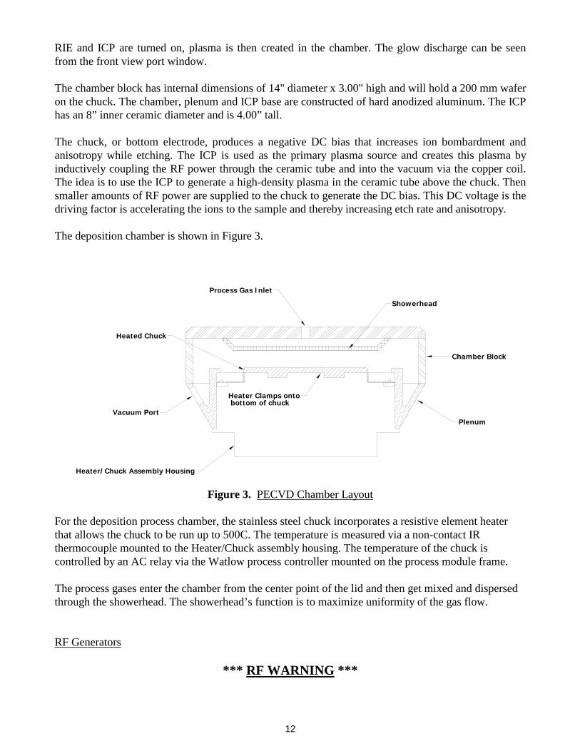
RIE and ICP are turned on, plasma is then created in the chamber. The glow discharge can be seen from the front view port window. The chamber block has internal dimensions of 14" diameter x 3.00" high and will hold a 200 mm wafer on the chuck. The chamber, plenum and ICP base are constructed of hard anodized aluminum. The ICP has an 8” inner ceramic diameter and is 4.00” tall. The chuck, or bottom electrode, produces a negative DC bias that increases ion bombardment and anisotropy while etching. The ICP is used as the primary plasma source and creates this plasma by inductively coupling the RF power through the ceramic tube and into the vacuum via the copper coil. The idea is to use the ICP to generate a high-density plasma in the ceramic tube above the chuck. Then smaller amounts of RF power are supplied to the chuck to generate the DC bias. This DC voltage is the driving factor is accelerating the ions to the sample and thereby increasing etch rate and anisotropy. The deposition chamber is shown in Figure 3.
Process Gas Inlet
Showerhead
Heated Chuck
Vacuum Port
Heater Clamps ontobottom of chuck
Chamber Block
Plenum
Heater/Chuck Assembly Housing
Figure 3. PECVD Chamber Layout
For the deposition process chamber, the stainless steel chuck incorporates a resistive element heater that allows the chuck to be run up to 500C. The temperature is measured via a non-contact IR thermocouple mounted to the Heater/Chuck assembly housing. The temperature of the chuck is controlled by an AC relay via the Watlow process controller mounted on the process module frame. The process gases enter the chamber from the center point of the lid and then get mixed and dispersed through the showerhead. The showerhead’s function is to maximize uniformity of the gas flow. RF Generators
*** RF WARNING ***

13
This machine uses RF frequency power. Care should be taken in its use. DO NOT operate this machine with any RF component enclosures open. These components should be service by trained personnel only. The frequency and power levels of the RF generators are as follows: Advanced Energy RFG 3001 1500 Watts maximum power @ 13.56Mhz Advanced Energy RFX 600A 600 Watts maximum power @ 13.56Mhz Seren L300 300 Watts maximum power @ 100 kHz For the etch process modules there can be up to two RF generators; the first is for the ICP source and the second is for the RIE source. Trion Technology uses the following high frequency RF generators. Advanced Energy RFG 3001 1500 Watt, 13.56 Mhz. Advanced Energy RFX 600A 600 Watt, 13.56Mhz. For the deposition process module, the chuck bias is generated by the following low frequency generator: Seren IPS L300 300 Watt, 100 kHz. The power level and on/off functions are controlled from the process control computer on each individual process modules. For further information see the RF generator manuals in the appendices. Automatic RF Tuning – Etch Chambers The RF generators supply a predetermined amount of power to the ICP and RIE matching networks. The amount of power is set by the user via the process control computer and is called the FORWARD POWER. The electrical schematics for the RIE and ICP networks are shown below.

14
For the ICP, the RF power first enters the matching network at the Phase-Mag detector. Then is goes through CF1 (fixed capacitance) to ground while also going through C1 (variable capacitance). After C1, the power goes through the coil and then out through C2 (variable capacitance) and CF2 (fixed capacitance). The RIE matching network is shown in Figure 5 below and is similar to that of the ICP. The RF power first goes through the phase-mag detector and then through the rest of the network and into the plasma inside the vacuum chamber.
The overall impedance of each network must be 50 ohms in order to deliver the full load power. The network for both the ICP and RIE include the electrical impedance of the plasma. Plasma impedance is determined by process pressure, RF power input, and the species of gases flowing into the chamber. If the overall impedance of the system is not 50 ohms, then a certain amount of RF power essentially bounces off the network and gets reflected back to the generator itself. This is called the REFLECTED POWER. The actual RF power delivered to the chuck or the ICP plasma is given by: RF Delivered = FORWARD POWER – REFLECTED POWER
RF In
Phase-Mag C1
CF1
Coil
C2
CF2
Figure 4. ICP Electrical Schematic
RF Input
Plasma Region Inside Coil in Vacuum
C1
C2
Chuck
Phase-Mag
Chamber Walls
Plasma Region In Vacuum
Coil
Figure 5. RIE Electrical Schematic

15
In order to consistently deliver the proper power to the chamber, it is important to properly “match” the network impedance so that the REFLECTED POWER is near zero. We use the variable capacitors to tune the impedance of the networks to keep the reflected power to near zero. In order to have the system automatically keep the networks tuned, we employ a device that detects the phase and magnitude of the reflected wave. This is called the “PHASE-MAG” detector. The phase-mag picks off the level of reflected power and then sends two low voltage signals (-2 to +2 Vdc) to an op-amp, which in turn sends proportionally higher voltages (-15 to +15 Vdc) to two DC servo motor coupled to the shafts of the C1 and C2 capacitors. For example, let’s say that the process pressure is changed so that the reflected power goes from 0 watts to 25 watts. The phase-mag will now generate voltage signals to the op-amp proportional to the amount of reflected power. The op-amp in turn sends higher voltages to the DC servo motors, thus turning the capacitors and decreasing the reflected power until it is near zero. Trion Technology calibrates the phase-mag so that the networks tune to within 5% of the RF power set point value. Automatic RF Tuning – Deposition Chambers The situation is primarily the same for the PECVD system except that it uses low frequency RF. However, because of the nature of low frequency waves, a step-up transformer is used to match the 50 Ohm impedance of the chamber to the generator instead of the variable capacitor matching network on the etch systems. The number of primary and secondary windings on this transfer former determine the match and thus the amount of reflected power. Since this is not variable, one step-up transformer is used for varying process conditions. Generally this works fine and the reflected power is below 10% of the set point. However, there may be conditions where the reflected power is higher. In these cases, the operator simply needs to know that the true delivered power is the algebraic sum of the forward minus the reflected power. The generator itself will limit the output power if there is too much reflected power.

16
Manual Tuning – High Frequency If there is a problem with the phase-mag or op-amp circuit, there are switches that can be used to override the automatic tuning and allow the user to manually adjust the network impedance. The switches that control the override and manual tuning are located behind the console door (if still installed) in the equipment rack. The switch board has switches for 3 chambers, and two high frequency sources for each chamber. The switch panel is shown in Figure 6.
Figure 6. - Switch Card Panel
Chamber #2
Man.C2C1Man.
C2
Auto
Auto
Man. C1
Chamber #1
Auto
Auto
Man.
Chamber #3
C2C1Man.C2C1
C1 C2
Auto
C1
Auto
Man. C2
Each process chamber has two sets of switches, the upper set is for the ICP plasma source while the lower is for the RIE source. For deposition systems, there are no switches. To manually tune high frequency plasmas, follow the steps below. In this example we’ll be tuning the ICP source on Chamber #1.
1. Open the door at the center console of the system. 2. Locate the group of three tuner controls that correspond to the plasma source that you wish to
tune. 3. Flip the “AUTO/MAN” switch to the fully down position. This switch has 3 positions; up =
automatic, middle = neutral (or no action), down = manual. 4. While looking at the computer screen with the process running, notice the amount of reflected
power for RF #1 (which is the ICP). 5. Adjust the “C1” switch so that the reflected power decreases. This switch is momentary so
when you release it, it will return to the center, or neutral position. If the reflected power increases, then reverse the direction on the switch. Keep adjusting this switch until the reflected power is at a minimum.
6. Then adjust the “C2” switch in the same manner until the reflected power again goes to a minimum.
7. Repeat steps 5 and 6 iteratively until the reflected power gets to near zero. 8. Leave the “AUTO/MAN” switch in the manual (or down) position. Putting it back to the
automatic position may increase the reflected power if the automatic tuning control circuit is not functioning properly or is out of range.
Figure 6. Switch Card Panel

17
Process Module Controller
Each process module comes with a Pentium based process control computer that controls all of the digital and analog instruments. This computer is connected to the main console computer via an RS-232 serial cable. The Trion designed data acquisition board has 12 analog output channels (8 bit resolution), which control the 6 gas channels, process pressure, chuck temperature (on deposition systems only), and the RF power. The system also comes with 16 channels of 12 bit analog input. The DAQ board and controller are run by LabView for Windows software. All processing parameters can be programmed by the user on the main console computer and stored into recipes files on the hard drive and/or on a floppy drive. Up to fifteen process steps per recipe can be stored. The recipe information is downloaded from the main console computer to the individual process module controllers before being. Vacuum System A schematic of the vacuum system is shown below in Figure 6. This consists of the chamber, load lock, gas distribution manifold, throttle valve, turbo pump and the two roughing pumps. A detailed gas cabinet schematic is shown later.
RoughingPump Turbo Pump
Turbo GateValve
Roughing Valve
Turbo Iso Valve
Throttle Valve
ChamberLoad Lock
PumpRoughing
Process Gas Line
Gas Cabinet
PneumaticShut Off Valves
MFC
Process Gas Inlets
ReactorGate Valve
Figure 7. - Vacuum Schematic
Load Station
Load GateValve
VentN2
Recirculating Chiller The recirculating chiller is capable of removing at least 2500 BTU/hr at 20C. It is used to cool the RIE process chamber, the turbo pump and the ICP source. The temperature set point is controlled from the front panel on the unit and be can set anywhere from 5 to 25C. For deposition process chambers the cooling loops includes the plenum walls. Trion Technology recommends the chiller be set to 20C for the system. For further information refer to the manufacturer’s manual in the appendix of this manual.
Figure 7. Vacuum Schematic

18
Laser Endpoint Detection System The etch process chambers can be fitted out with a laser-base interferometer endpoint system. This endpoint detection system utilizes a 670nm laser with a spot size that can be focused down to ~ 1mm in diameter on the wafer or sample. The reflected beam from the wafer is received by a light sensitive photocell circuit, which converts the intensity of the light into an analog voltage signal. This signal is then sent to the I/O board in the process computer. As the thickness of the material changes during the etch process, the photocell circuit detects the destructive interference and displays this change in voltage versus time on the computer display. This data trace is automatically stored on the hard drive for each process run and can be access later for transfer onto to floppy. Knowing the characteristics of the film (such as material structure and index of refraction), the real time laser signal can be used to determine the endpoint of the etch. This endpoint may either be complete removal of a material layer or a certain depth etch into that layer. Figure 8 shows the laser install onto an etch chamber lid.
Chuck
Lid
X-Y Stage Knobs
Chamber Walls
Photocell DetectorLaser with Focus Knob
Circuit Board
Telephoto Lens
CCD Camera
with Adjust Pot
Figure 8. Laser Interferometer Assembly

19
IV) SAFETY SPECIFICATIONS
SAFETY STANDARDS The Trion Oracle was built with standard safety requirements in mind. Purchased electrical components meet national UL standards where applicable and materials used in the machine's construction meet National Electric and Fire Codes. This machine has been found to meet SEMI S2-93 product safety guidelines. The machine has the proper ANSI Z535 hazard warning labels where appropriate including high voltage, chemical, excessive weight, high temperature and RF. LOCK OUT/TAG OUT Electrical power is supplied from the house system to the Oracle system at only two locations; the main console AC distribution and the Pump Control NEMA Box. Figure 9 shows a diagram of this electrical distribution system.
AC Distribution
Main Console
HouseBreakerPanel
Facility Wall5 Prong, Twist Lock
Receptacle
Main Console
PumpControlNEMABox
Chamber #1Pump
Chamber #2Pump
Chamber #3Pump
Load LockPump
Figure 9. Main Electrical Distribution Diagram
The main console AC distribution is connected to the house breaker panel via a 5 prong twist-lock cord plug. The three-phase process chamber roughing pumps are connected to the house breaker panel via the Pump Control NEMA Box. The power cords from the pump motors can either be hard wired through a knockout in this box to the main contactors inside or supplied with a twist lock disconnect. Just upstream of these contactors are 10 Amp, 3-pole circuit breakers. The incoming power from the house is wired to the “LINE” side of this breaker. This NEMA box is to be pad-locked closed unless the house breaker has been locked out as described below.

20
Procedure For Servicing Hardware: 1. If any service work is to be performed on the system other than routine system maintenance, the
user must first press the EMO button on the front panel of the system. 2. Next, the user must unplug the cord plug from the wall outlet. 3. The Cord lockout cap must be locked onto the cord plug. This lockout cap must have the tag
“DANGER DO NOT OPERATE” attached to it and visible. This will prevent any system component from turning on. It is now safe to remove modules and/or repair them in place following proper guidelines set down by Trion Technology. Although the Pump Control NEMA Box still has electrical power coming into the contactor, with the AC distribution unplugged this contactor can not be energized. However, if service work needs to be performed on the process chamber roughing pump OR the NEMA control box, the following procedure must ALSO be followed. 1. Shut off the main house circuit breaker feeding the Pump Control NEMA Box. 2. Using the circuit breaker lockout, lock this house circuit breaker in the OFF position. This
lockout must have the tag “DANGER EQUIPMENT LOCKED OUT TO PROTECT WORKERS” attached and visible.
3. The user is now free to unlock the NEMA box if necessary and perform any service as needed. EMERGENCY OFF SYSTEM Figure 9 shows a diagram of the electrical control circuitry and buttons. There are 4 control buttons as labeled in the figure; EMO, START, STOP and PUMP EMO. START This momentary button energizes the all of the AC relays (K1 through K5) inside the
AC distribution module and:
- distributes 208VAC to the following outlets; J-1 (AUX) J-2 (Chamber #1 Power) J-3 (Chamber #2 Power) J-4 (Chamber #3 Power)
- distributes 110VAC to outlets J-5 and J-6 (Main power) this turns on the computer and other equipment in the console.
STOP This momentary button de-energizes every AC relay and therefore shuts off power to
every instrument and process module on the entire Oracle system. PUMP EMO This twist-to-release button de-energizes every AC relay and therefore shuts off power
to every instrument and process module on the entire Oracle system.

21
EMO This twist-to-release button de-energizes every AC relay and therefore shuts off power
to every instrument and process module on the entire Oracle system.
After either the EMO or PUMP EMO buttons are unlocked, no component of the system will turn on again until the START button is pressed in.
INTERLOCKS The Oracle system has hardware interlocks that place the machine in a safe mode when tripped. These interlocks protect against a loss of water coolant flow, a loss of the house exhaust to the gas cabinet and pumps, and a hazardous gas leak. The table below describes the interlocks, their location and what they control in the advent of an error or alarm condition.
Table 1. Interlock Summary
Interlock Location Purpose Actions Water flow switch.
Mounted to the chamber coolant outlet port.
To detect a loss of water coolant flow.
N.O. switch opens when the water flow stops. This tells the computer to shut down the gas valves, heater (on PECVD chamber) and RF power.
Exhaust flow switch.
Mounted to the cabinet exhaust duct.
To detect loss of flow exhaust system.
N.C. switch opens when the exhaust flow stops. This activates the EMO circuit and all power to the system is shut off. A wobbling audible alarm also sounds near the tool.
Load Station Lid Switch.
Under the load station lid hinge plate
To detect when the lid is closed.
N.O. switch aborts wafer load or unloading sequences.
22
Interlock Location Purpose Actions
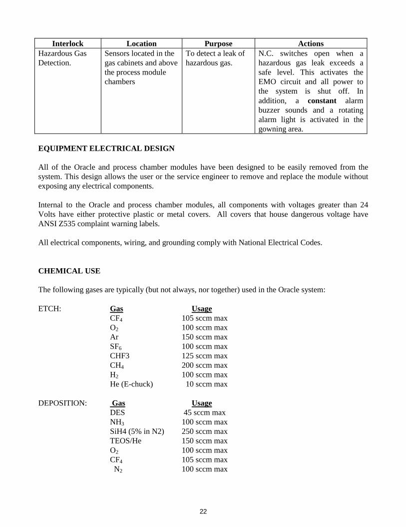
Hazardous Gas Detection.
Sensors located in the gas cabinets and above the process module chambers
To detect a leak of hazardous gas.
N.C. switches open when a hazardous gas leak exceeds a safe level. This activates the EMO circuit and all power to the system is shut off. In addition, a constant alarm buzzer sounds and a rotating alarm light is activated in the gowning area.
EQUIPMENT ELECTRICAL DESIGN All of the Oracle and process chamber modules have been designed to be easily removed from the system. This design allows the user or the service engineer to remove and replace the module without exposing any electrical components. Internal to the Oracle and process chamber modules, all components with voltages greater than 24 Volts have either protective plastic or metal covers. All covers that house dangerous voltage have ANSI Z535 complaint warning labels. All electrical components, wiring, and grounding comply with National Electrical Codes. CHEMICAL USE The following gases are typically (but not always, nor together) used in the Oracle system: ETCH: Gas Usage CF4 105 sccm max O2 100 sccm max Ar 150 sccm max SF6 100 sccm max CHF3 125 sccm max CH4 200 sccm max H2 100 sccm max He (E-chuck) 10 sccm max DEPOSITION: Gas Usage DES 45 sccm max NH3 100 sccm max SiH4 (5% in N2) 250 sccm max TEOS/He 150 sccm max O2 100 sccm max CF4 105 sccm max N2 100 sccm max

23
When a particular etch process is complete, the process controller automatically maintains a vacuum in the chamber for 20 seconds after processing to insure complete removal of any residual by-products. (This time can be increased through software if desired). A follow on process step can be added that purges the chamber with nitrogen to further clear out residual gases. The controller is also designed such that the reactor remains under vacuum when the system is idle. The load lock eliminates the need for the user to open the chamber during normal operation and therefore, there is no contact with process gases during normal operation. EMISSIONS There should be no harmful chemical emissions during the normal operation of this equipment. The reaction chamber and vacuum pumps are sufficiently exhausted to prevent this occurrence. LABELING All piping is labeled with the name of the gas contained within. All system wiring is color coded in accordance to NEC requirements. All hazardous locations are labeled with ANSI Z535 compliant labels. EARTHQUAKE PROTECTION The system will not overbalance until it is tipped more than 22o and is sturdily built into a 1.8" square extruded aluminum frame. In addition, the system should be bolted to the facility floor as required by local customer or city ordinances. MECHANICAL SAFETY There are no sharp protruding edges that can be hazardous. The only moving parts are the robot end effector and the gate valve between the load lock and the process chamber. The robot motor’s stall torque is low enough that no injury will occur should the end effector move while the user’s hand is in the way.

24
“WHAT IF” HAZARD ANALYSIS The following table shows the risk assessment of the Oracle cluster system.
Table 2. What If? Hazard Summary
What If? Consequences Protection Computer lockup Process continues to run at last set
points. Possible sample damage. None
Computer failure Set points go to zero and all normally closed valves close
Failsafe
Loss of cooling water
RF generation ceases, process is impacted, potential o-ring damage
Flow switch that cuts off all RF power, gas flows and heater voltages.
Chiller coolant leak
Wet floor Small coolant volume, well placed and baffled electrical enclosures
Loss of pump exhaust
Build up of process gases in pump exhaust lines. Possible pump degradation if exhaust pressure is too high.
Exhaust pressure switch that EMO’s the system and thus prevents further gas flow.
Loss of cabinet exhaust
If a gas leak then occurs inside the cabinet hazardous gas can leak out into user environment. This is a double failure and rare.
Exhaust pressure switch that EMO’s the system and thus prevents further gas flow. Also, toxic gas sensors inside cabinet will EMO the tool if a leak is detected.
Toxic Gas Leak Hazard to personnel Customer supplied gas detectors are wired into Trion system and EMO the system in the event of a toxic gas leak

25
V) INSTALLATION
INSPECTION The Oracle cluster system and its process modules are completely tested and inspected at the factory before shipping. The user should inspect the shipping containers before unpacking the instrument. If there are signs of damage to the containers, make note of the damage and report it to the shipping company and TRION TECHNOLOGY immediately. After uncrating inspect the instrument for any damage to the enclosure, the chamber, switches, and other components. If there are any damaged or missing components, notify your sales representative or the TRION Service Department. FACILITIES The Oracle requires the following facilities for operation: AC POWER
Console: 208VAC 30A, 3-phase, 5-wire twist lock receptacle 1 Ground, 1 Neutral, 3 Lines (hot)
NEMA Box 208VAC 60A (max), 3-phase, 1 Ground, 3 Lines (hot) GASES Pneumatic Actuation: NITROGEN - 80 psi, 1 lpm Process Gases: OXYGEN - 15 psi, 100 sccm CF4 - 15 psi, 100 sccm ARGON - 15 psi, 100 sccm NF3 - 15 psi, 100 sccm
SF6 - 15 psi, 100 sccm CHF4 - 15 psi, 100 sccm
H2 - 15 psi, 100 sccm (Note: all process gas fittings are 1/4" VCR) PUMP EXHAUST Due to the various pumps that Trion has used, the following table
applies.
Table 3.
Pump Facilities Specifications
Pump Flow Requirement
Flange Size
Varian CP-451 10 CFM, max NW-25 Varian DS-602 10 CFM, max NW-25 Alcatel 2021C2 10 CFM, max NW-25

26
Pump Flow Requirement
Flange Size
Varian CP-700 20 CFM, max NW-40 Alcatel 2033C2 20 CFM, max NW-40
Varian Vsp30 Dry Pump 20 CFM, max NW-40 Pfeiffer PDP100 Dry Pump 30 CFM, max NW-25
CABINET EXHAUST 200 cfm per cabinet, 6” ID Duct. Duct material must be non-
flammable. If local authorities require abatement then follow the pertinent regulations for the chemistries used.
COOLING WATER 2.0 l/min @ 20 deg C
50/50 Mixture of Ethylene Glycol and DI water or 1.0 to 4.0 M resistivity 3/8” SWAGELOCK FITTINGS
INSTALLATION PROCEDURE
1. Place the CVT in the position in the room where desired. 2. Using a 13mm open-end wrench, lower 3 of the leveling feet until the top of the CVT
chamber is approximately 44.75” inches from the floor. (This dimension is NOT measured to the top of the lid that sits on the CVT chamber).
3. Level the CVT at this approximate height. 4. Roll process chamber #2 up to the CVT at position #2 as shown in Figure 10 below.
CHAMBER #2
STATIONLOAD
CHAMBER #3
CVT
CHAMBER #1
Figure 10. Plan View of System
5. Making sure that the two dowel pins are installed in the chamber face, lift and mate the chamber face to the gate valve.

27
6. Use the two claw clamps to clamp the chamber face to the gate valve. However, do not fully tighten these bolts.
7. Again using a 13mm wrench, lower the leveling feet on the process module frame until process chamber #2 is level. Check to make sure the chamber face is parallel to the gate valve.
8. Finish tightening the two clamp bolts. 9. Repeat this procedure for the remaining process modules. 10. Once all the process modules are connected and everything is level, go around to all the
leveling feet (on the CVT and process modules) and tighten the jam nut on the feet. The assembly should now be fairly rigid.
11. Place the pumps for the system in their final positions. The pumps should be placed as close to the rear of the system as possible to limit conductance losses.
12. Run a vacuum fore line from the load lock roughing pump to the NW-25 vacuum flange on the inside of the CVT. There is a single pump for the load lock and loading station. This line can either be reinforced flexible tubing, flexible stainless or hard stainless material.
13. Run stainless vacuum fore lines from each chamber pump to the exit flange on the process modules. Some modules will have NW-25 flanges while others will have NW-40 flanges. Adapt where necessary. These lines must be stainless for compatibility with process gases and should include a flexible stainless section to isolate vibration from the pumps. Again, long runs of fore line and numerous bends are to be minimized.
14. Connect the pneumatic CDA or N2 to the CVT solenoid pack. This is located inside the CVT and can be accessed by removing one of the black side panels. The fitting is a ¼” one-touch fitting for poly or Teflon tubing. Hard stainless line can be used as well but the inlet fitting on the solenoid pack must be changed to a ¼” Swagelock male connector (1/8” NPT).
15. Connect the pneumatic CDA or N2 to each process module’s solenoid pack. All pneumatic supplies should have a separate shut-off valve and gauge. Leave the valves off. Trion Technology’s installation technician will complete the pneumatic tubing connections and then energize the lines.
16. Place the console in the desired location. Connect the main AC distribution’s power cord into the facility wall. The unit comes equipped with a 5-prong, 3-phase twist lock plug. This house facility should supply 30Amps @ 208V 3-phase along with a neutral line. The Trion service technician will connect all the other instrument cables from the console upon his visit.
17. Mount the gas cabinets to the wall. The cabinets are heavy and need to be mounted to uni-strut brackets that are firmly secured to the wall and/or floor and ceiling. Position each process module’s gas cabinet near its appropriate chamber, even if they are mounted in a case.
18. Run process gas lines from the output of each cabinet to the input of the particular process chamber. Etch process modules have a single cabinet output while PECVD modules have two process gas outlets from the cabinet. The cabinet outlets and chamber inlets have ¼” male VCR bulkhead connections. Where the gas lines connect to the process chamber inlets, a short section of flexible stainless braided line should be used to allow for lid opening and closing during maintenance cleanings.
19. Connect the house process gases to the bottom inlets on the gas cabinets. These connections are also ¼” male VCR. The customer is responsible for supplying the gas cylinders, pressure regulators, shut off valves and pressure gauges for each gas. Leak test these process gas supply lines. The delivery pressure for each gas should be set to 10-15 psi.

28
20. For corrosive gas cabinets with cycle purge plumbing, also connect purge N2 to the fitting on the bottom of the cabinet labeled “Purge N2”. The delivery pressure should be set at 10-15 psi.
21. Also for corrosive gas cabinets, run a solid ¼” OD stainless tube from the cabinet port labeled “Vacuum” to a position near the inlet of the process chamber pump.
22. The Trion service technician will connect the MFC instrument control cables and pneumatic tubing upon installation.
23. Mount the Pump Control NEMA enclosure on the wall near the pumps. 24. Wire into this box the necessary power for the system’s pumps. The total current load will
depend on the pumps used. The following table can be used as a guide.
Table 4. Pump Electrical Specifications
Pump Voltage
Normal FLA
Varian CP-451 208V, 1ph 4 Varian DS-602 208V, 1ph 6.5 Alcatel 2021C2 208V, 1ph 4 Varian CP-700 208V, 3ph 7.5 Alcatel 2033C2 208V, 3ph 7.5
Varian Vsp 30 Dry Pump 208V, 3ph 7 Pfeiffer PDP100 Dry Pump 208V, 3ph 6
25. Connect the pump power cords up to the output of the NEMA Pump control box. These can
either be hard wired to the contactors inside or connected using twist lock cord disconnects. 26. There is a small control cable that runs from the Pump control box to the console unit and
this will be installed by the Trion service representative. 27. Connect cooling water lines to the process modules. These should be run with 3/8” or ½”
OD tubing to minimize pressure drop. If possible, each process module should have it’s own on/off valves and flow gauge.

29
VI) SYSTEM OPERATION The Oracle system is operated from a touch screen located on the main console unit (a mouse may also be supplied as a secondary pointing device). The console houses a master computer (known as the console computer) along with the main AC distribution unit, automatching switches and miscellaneous other equipment. Each process module has its own computer that runs independently from the master computer and simply supplies process data and operation status over RS-232 serial cables. Process recipe files are all stored on the master computer and downloaded to the process module computers before operation. The following section will detail the various operations of the tool and its components. System Start Up: 1. Ensure that both the console “EMO” button and the Pump Control NEMA box “EMO” button
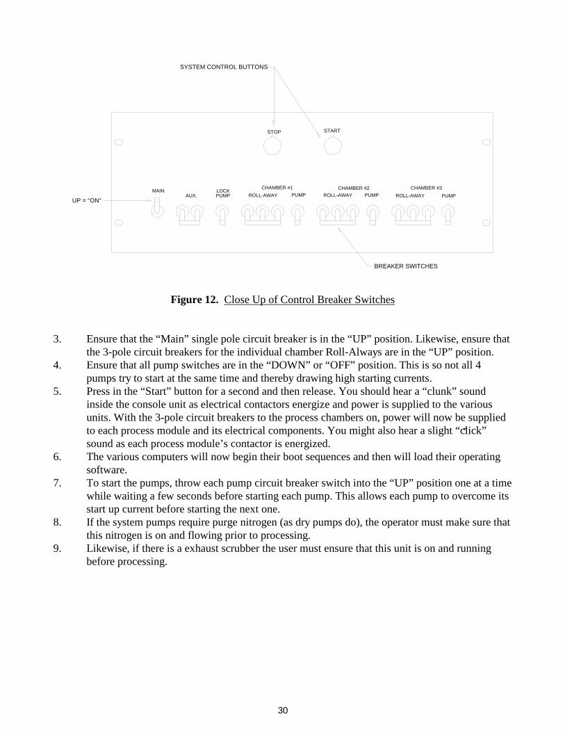
are not pressed in. 2. Locate the “Main” control circuit breaker on the front of the AC distribution unit. A sketch of
the console is shown in Figure 11 while a close up of the control breaker switches in shown in Figure 12.
"Stop" Button
Tuning Switches
"Start" Button
Control Breakers
Console Computer
ScreenTouch
Figure 11. Console Front View
30
BREAKER SWITCHES
PUMPUP = "ON"
AUX.LOCKPUMP ROLL-AWAY
MAIN CHAMBER #1
STOP
SYSTEM CONTROL BUTTONS
PUMPROLL-AWAYPUMPROLL-AWAYCHAMBER #2 CHAMBER #3
START
Figure 12.
Close Up of Control Breaker Switches
3. Ensure that the “Main” single pole circuit breaker is in the “UP” position. Likewise, ensure that
the 3-pole circuit breakers for the individual chamber Roll-Always are in the “UP” position. 4. Ensure that all pump switches are in the “DOWN” or “OFF” position. This is so not all 4
pumps try to start at the same time and thereby drawing high starting currents. 5. Press in the “Start” button for a second and then release. You should hear a “clunk” sound
inside the console unit as electrical contactors energize and power is supplied to the various units. With the 3-pole circuit breakers to the process chambers on, power will now be supplied to each process module and its electrical components. You might also hear a slight “click” sound as each process module’s contactor is energized.
6. The various computers will now begin their boot sequences and then will load their operating software.
7. To start the pumps, throw each pump circuit breaker switch into the “UP” position one at a time while waiting a few seconds before starting each pump. This allows each pump to overcome its start up current before starting the next one.
8. If the system pumps require purge nitrogen (as dry pumps do), the operator must make sure that this nitrogen is on and flowing prior to processing.
9. Likewise, if there is a exhaust scrubber the user must ensure that this unit is on and running before processing.

31
Logging Onto the System: After the console computer’s software loads, it will first initialize the system hardware by performing the following steps.
1) Initializes the robot by loading velocity and acceleration parameters, homing the extension axis and homing the rotation axis.
2) Checking each COM port to see if a process module is connected. Since the process module computers usually take slightly longer to boot and load their software, the console computer may time out and register a certain process module as being “Off Line”. The COM port initialization screen is shown in Figure 13.
Figure 13.
System Initialization Screen
Here it shows that chamber #1 has established communications and is online while chamber #2 was not detected. This could be due to one of the following reasons:
a) No chamber #2 process module installed. b) Disconnected serial cable between host computer and process module computer. c) Process module does not have power. d) Process module’s computer is locked up or not set up for response. e) Process module’s computer has not booted up yet.
Figure 12 also shows that the host computer is trying to connect to chamber #3. If there no #3 chamber, or it is offline for maintenance, you can touch the “Skip Chamber” button to enable the software to record #3 as offline and proceed with the system initialization.
3) Software loads the main operator screen as shown in Figure 14. The system will default to no
one being logged on. In this case, none of the buttons on the main operator screen are active except for the “Log On” and “Exit” buttons.

32
4) Touch the “Log On” button and the log on dialog box will pop up. Enter in the username and password to enable the rest of the control buttons on the main operator’s screen.
If you have the correct access privilege, the “Hardware Setup” and “Maintenance” buttons will also be active. If the super user has limited your access, then these two buttons will remain inactive.
Figure 14.
Main Operator Screen
Loading a Recipe: All of the system’s recipe files are stored on the hard drive of the host computer. They are simply ACSII text files located in the following directories: Chamber #1: C:\RECIPES\CHAMBER1 Chamber #2: C:\RECIPES\CHAMBER2 Chamber #3: C:\RECIPES\CHAMBER3 In order to run a particular recipe you first need to load it from the host computer’s memory and then download it to the proper process module. In the following example we’ll assume that we are processing in chamber #1. The steps would be similar if processing in either of the other two chambers. 1) Touch the “Recipe #1” button to enter the recipe screen for process module #1. This screen is
shown in Figure 15.
33
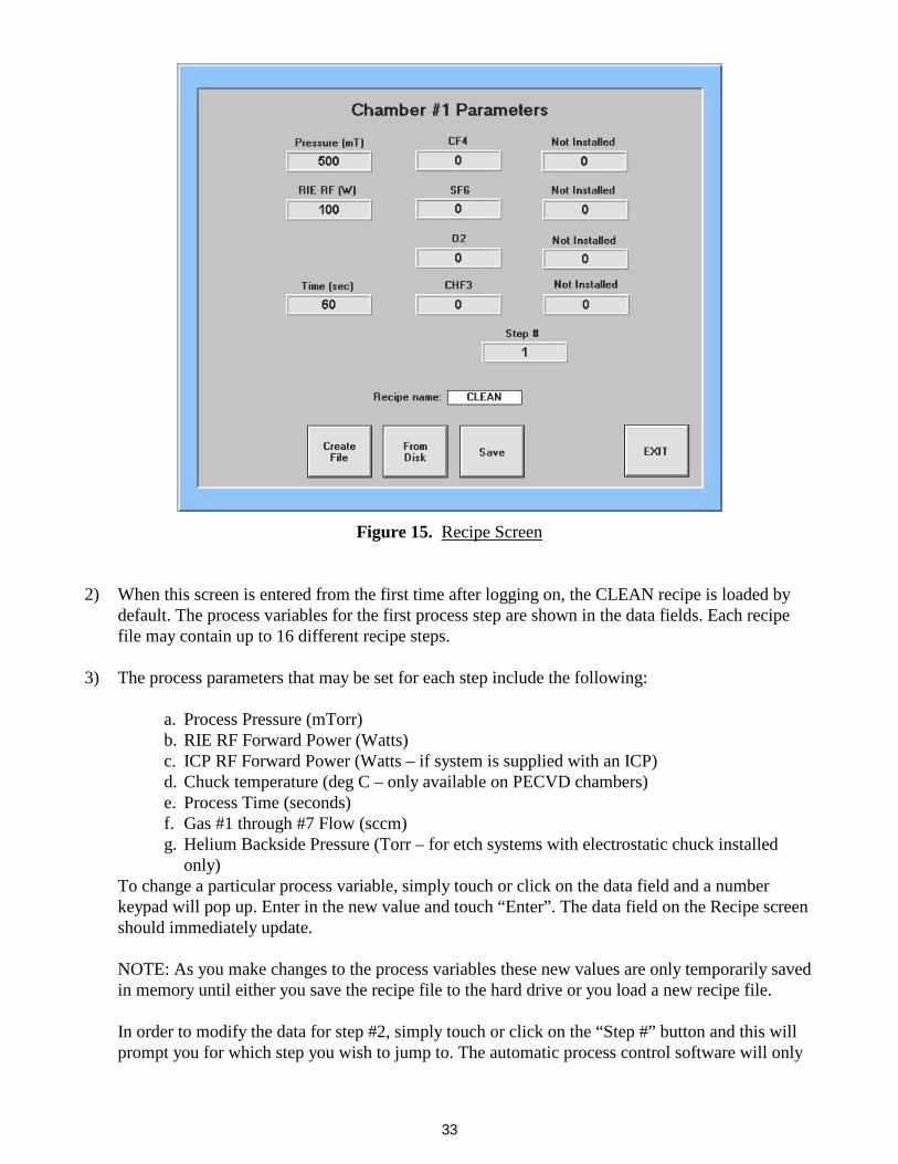
Figure 15. Recipe Screen
2) When this screen is entered from the first time after logging on, the CLEAN recipe is loaded by
default. The process variables for the first process step are shown in the data fields. Each recipe file may contain up to 16 different recipe steps.
3) The process parameters that may be set for each step include the following:
a. Process Pressure (mTorr) b. RIE RF Forward Power (Watts) c. ICP RF Forward Power (Watts – if system is supplied with an ICP) d. Chuck temperature (deg C – only available on PECVD chambers) e. Process Time (seconds) f. Gas #1 through #7 Flow (sccm) g. Helium Backside Pressure (Torr – for etch systems with electrostatic chuck installed
only) To change a particular process variable, simply touch or click on the data field and a number keypad will pop up. Enter in the new value and touch “Enter”. The data field on the Recipe screen should immediately update. NOTE: As you make changes to the process variables these new values are only temporarily saved in memory until either you save the recipe file to the hard drive or you load a new recipe file. In order to modify the data for step #2, simply touch or click on the “Step #” button and this will prompt you for which step you wish to jump to. The automatic process control software will only

34
execute a process step if the process time entry is non-zero. For example, if the time entry in step #1 is 60 seconds and that for step #2 is 0, then only the first step will be run. If you set step #2 time to 30 second and step #3 to zero, then the program will run the first two steps and then halt. The software will not skip steps. Dummy steps are handy for simply pumping out the chamber between steps or running a purge gas flow. To do this, simply enter a process time for the step and set the RF power to zero. Then you can either set a purge process gas to flow (such as nitrogen or argon) or simply pump out the chamber before starting the next process step.
4) To load a previously stored recipe file from the hard drive, touch the “From Disk” button on the
Recipe screen. The software will then load the “Files” screen shown in Figure 16.
Figure 16. File Screen
The current files stored on the hard drive for chamber #1 will be listed in boxes in the center portion of the screen. This screen will currently only hold 20 recipe files. If you require more than that you can store another 20 recipes on a floppy disk.
5) To load a new recipe file, simply touch or click on the box with the recipe name you want. A
dialog box will briefly pop up informing you that the new file is loading. When it has loaded all 16 steps, the dialog box will disappear and the “Current Recipe:” field in the upper right hand portion of the screen with update with the new name. Touch or click on “Exit” to return to the Files screen.
6) To create a new recipe file, touch or click on the “Create File” button on the Recipe screen. This
will cause a dialog box to pop up prompting you for the new filename. Use the keyboard to enter in a new name and hit the enter key on the keyboard, or touch the “Ok” button in the file dialog box.

35
A new recipe file will be created with all the process variables set to zero. You would now have to program in the data and save the save to the hard drive.
7) To save any file that has been changed simply touch or click on the “Save” button on the Recipe
screen. The software will ask you for confirmation that you wish to save the data (thereby overwriting any previous data in that recipe file). Touch “Okay” to have the program save the file to disk.
8) Once you have modified, created or loaded your recipe, touch “Exit” to return to the Main
Operator Screen. 9) The label “#1 File Loaded:” should now be updated to the particular file that was loaded. The final
step before running the recipe is to download this data to the process module’s computer. Do this by touching or clicking on the “Down Load #1” button. A status box will pop up showing that various steps being downloaded.
The chamber is now ready run the process, however that wafer or sample needs to be loaded first. NOTE: Some sort of wafer or blank transfer disk must be loaded into a chamber before running a process. This is because the transfer lift pins in the chuck may suffer damage when in the plasma if they are not covered up. This includes running CLEAN recipes.
Loading a Wafer or Sample Plate: The wafer is loaded into the chamber via a transfer load lock which itself is separated into two sections; the central load lock (which includes the robot) and the load station. The load station is simply a small volume transfer chamber that allows the larger robot and load lock to be kept under vacuum all of the time. This smaller volume shortens pump down time during the load and unload sequences. To load a wafer or sample plate to chamber #1, follow the steps below: 1) Touch or click on the “Load #1” button from the Main Operator’s screen. The “#1 Loaded” LED
should be off, or gray in color. This signifies that there is currently no wafer loaded into chamber #1. If the “#1 Loaded” LED is green, then there is a wafer currently loaded into chamber #1 and the “Load #1” button will now be labeled “Unload #1” and you can NOT load a wafer into the chamber until the one is unloaded from the chamber.
2) The system will begin moving the robot into the correct position and then will pop up a dialog box
asking if the user wishes to vent the load station. The loading station can either be at atmosphere or still under vacuum, depending on how the system was used last. If the user can’t open the load station lid, then he will need to vent the load station before loading the wafer into it. However, if the station is at atmosphere then he can skip this step and NOT vent the load station.
3) Once this selection has been chosen the lift pins inside the load station will lift up, wait a few
seconds, and then lower themselves. This is done to break any stickiness between the lift pins and the load station body. When the pins sit idle for long periods of time they can at first move roughly

36
and cause a wafer to bounce around. This pin exercise prevents any jerky motion during the actual wafer loading sequence.
4) After the pins have lowered, the computer will prompt the user to open the lid and place the wafer
or sample plate onto the load station platen. The wafer will be centered automatically via insertable centering rings. The pop dialog also instructs the user to touch the “OKAY” button once he has closed the lid.
If the user touches or clicks on the “OKAY” button prior to closing the lid, the system will detect that the lid is open and abort the load procedure. Ensure that the lid is closed before acknowledging the computer at this step.
5) The computer will now control the system to transfer the wafer from the load station into process
chamber #1. It does this by the following sequence of steps: a. Pump down the load station and load lock to a pre-set vacuum level (on the order of
300-500mTorr). b. Open the transfer gate valve between the load station and the central load lock. c. Raise the load station lift pins and thereby lifting the wafer. d. Extending the robot arm into the load station and under the wafer. e. Lower the lift pins to place the wafer onto the robot’s end effector. f. Retract the robot arm back into the central load lock. g. Close the load station transfer gate valve while rotating the robot to process chamber #1. h. Waits until the pressure in the load lock has dropped below approximately 200-
250mTorr. i. Checks the current pressure inside the chamber. If the pressure inside the chamber is too
high, then the load procedure aborts and returns the wafer back to the load station. If the pressure level is below 100mTorr, the load sequence continues.
j. Opens the transfer gate valve to the #1 process chamber. k. Extends the arm into the chamber. l. Raises the chamber lift pins to lift the wafer off of the robot’s end effector. m. Retracts the arm into the central load lock. n. Closes the chamber #1 transfer gate valve. o. Vents the load station back to atmosphere.
While this process proceeds the screen gives updates on the current step in the process. There is an “ABORT” button active that allows the user to immediately halt the robot arm and any gate valve from moving. This should only be done when it is clear there is some abnormal situation present (such as the wafer having slipped off of the end effector).
6) After the screen returns to the Main Operator’s screen, the wafer is successfully loaded and the “#1
Loaded” LED should be lit green. In the advent that the computer gets turned off or power is lost, the software will remember the current status of the three “#x Loaded” buttons (x being either 1, 2 or 3 here).
Setting Up the Laser: If the process chamber is configured with a laser interferometer detector the next step before running a recipe would be to locate the laser spot size onto a desired feature on the wafer.

37
1) From the Main Operator’s screen touch the “Laser Setup” button. (Only process chambers with
a laser will have this button displayed). 2) On the Laser Setup screen you will find a large digital display for the reflected laser voltage.
There are also rectangular button controls for the Laser and Lamp. 3) First, touch the “Lamp” button to turn on the light bulb inside the laser assembly. This will
provide enough illumination down into the chamber. A black and white image should be visible on the TV monitor of your wafer. NOTE: If the wafer is unpatterned, then you will not be able to see the wafer since there is not enough light scattered off of it.
4) Turn on the “Laser” button and a small dot should appear on the wafer. 5) Use the X-Y stage knobs to move the laser to the desired position in the pattern. Be aware that
there is only about 0.5” window of movement for the laser. 6) Turn off the Lamp and look at the voltage being detected. If the laser is properly aligned the
reflected beam is hitting the photocell the voltage will be low (~1.0 – 2.0 volts). There is a potentiometer located on the detector circuit board to adjust the voltage level of the signal. This should set up upon the system’s installation and should not be adjusted after that.
7) Turn off the Laser and then notice the photocell voltage with no beam. This should be high, 5volts.
NOTE: If the photocell voltage is still 5.0volts when the Laser is ON, then the reflected beam is not hitting the cell. This may be caused by a wafer being misloaded and sitting in the chamber at a slight angle.
8) Once you have confirmed the laser spot position and that the reflected beam is aligned on the
photocell, exit this screen. Running a Process – Automatically: There are two ways to run the process recipe in the chamber. The first method (and recommended) is the Automatic Process Control and the second is Manual Process Control. In Automatic control, the computer performs all steps of the recipe in the correct sequence and faults out when certain process variables get out of tolerance to their set points. Manual process control allows the user a certain freedom in changing variables during the process and can be used for debugging problems. To being running a process Automatically, follow the procedures below (again, for this example we’ll assume that we are processing in chamber #1): 1) Touch the “Start #1” button. This sends a signal to the chamber #1 computer to start the automatic
sequence with the recipe variables that have been most recently downloaded to it from the host computer.
2) The “#1 Running” LED should now turn green. The host computer will stay in this Main
Operator’s screen as chamber #1 runs the process. This is to allow the user to possibly load another wafer into a different chamber and start another process there. All three process chambers can be running at the same time if desired.

38
3) To watch the process proceed through it’s sequence, touch or click on the “Get #1 Status” button.
This will bring up the automatic process status screen for that chamber, shown below in Figure 17.
The only active buttons on this screen are the “Abort” and “Exit” buttons. The screen shows all the process variable’s “Set” and “Read” values. The “Set” value is that programmed in the recipe file while the “Read” value is what that particular instrument is currently doing. These set values can NOT be changed in this screen. Near the bottom of the screen the sequence status is given via Vacuum, Pressure, Gas Flow and RF LED indicators. As shown in Figure 16 the oxygen process gas is flowing at 49 sccm and the throttle valve has adjusted the chamber pressure to 502mTorr. The plasma is on and the forward power delivered by the RF generator is 98 Watts with 2 Watts being reflected from the matching network. The process time counter starts at the process time set (in this instance 60 seconds) and counts down to zero. The “Laser Trace” button is only present when the chamber has been configured with a laser endpoint system. This is set up in the “Hardware Setup” screen described in the Maintenance section of this manual.
Figure 17. Automatic Process Status Screen
4) The automatic process proceeds along the following steps:
a. Open the vacuum valve and pressure gauge isolation valve. This allows the instrumentation to measure the pressure inside the chamber with no gases flowing. The throttle valve is 100% open at this time.
b. When the pressure reading drops below a set base pressure (100mT), the manifold valves inside the gas cabinet open for any gases commanded are opened and the MFCs are commanded to control to their set point. At this time the throttle valve begins regulating the chamber pressure to that value set.

39
c. The computer now waits for each MFC to reach its set value and for the chamber pressure to come up to its set value. Once these are within a certain tolerance band, the computer waits another 5 seconds for stabilization.
d. Then the RF generator is commanded to output RF and the timer begins counting down to zero.
e. Once the timer reaches zero, the RF and gas flows are shut off and the chamber is pumped out for a predetermined period (~ 15 seconds).
f. After this pump out stage, the computer look at step #2 of the process recipe and if the time entry is non-zero it loads the new process variables and repeats these process steps. If the step #2 time entry is zero, then the computer leaves the vacuum valves open and returns to the Main Operator’s screen.
5) While the process is running, the user may exit this status screen to perform other operations on the tool. To exit this screen and keep the process running, touch or click on the “Exit” button.
6) The operator can immediately stop any process in this screen by touching the “Abort” button. This
will close all gas valves, shut of any RF output, and leave the vacuum valves open to pump out the chamber. Then the computer will be returned to the Main Operator’s screen.
7) If the process is running and the user is on the Main Operator’s screen, the process can be quickly
terminated by touching or clicking on the “Abort #1” button on this screen. 8) Once the process has ended (or been aborted), the “#1 Running” LED should go out and the wafer
can be unloaded or another process recipe can be downloaded and run with the wafer remaining inside the chamber.
9) For watching the laser interferometer signal, touch the “Laser Trace” button. A representative chart
is shown in Figure 18. The laser voltage is displayed on the graph in volts. The time axis on the bottom is in seconds. The graph time starts when the user enters this screen that will not necessarily be the process time (defined as when the RF power is on).

40
Figure 18. Laser Trace Display The scales of the axes can be manipulated by using the mouse and double-clicking on either the
max or min value. For example, Figure 18 shows the time history from 300 seconds into the etch to the current time of ~ 655 seconds (the data display for “Etch Time” is not correct for this example chart). If the user wanted to view the entire history from time=0, then he would double-click on the min time axis value of 300, enter the number 0 from the keyboard and hit the enter key. The graph will immediately update.
Likewise, the intensity axis can be manipulated to better see the magnitude of the waveform. The photocell detector circuit will only put out a maximum of 5 volts. However, the actual trace from a particular material may only be varying from 0.5 volts to 1.5 volts (peak-to-peak). Thus the operator may want to expand the graph by changing the max intensity scale value from 5.0 to 2.0. In order to use the laser trace to detect an endpoint to the etch it is important to know what the material structure is on the wafer. As the etch proceeds and removes an entire material layer, the laser trace should dramatically change in either period or magnitude. For example, if you are etching nitride from a bare silicon wafer the laser trace would change from approximately a sine wave to a flat line (or no interference). This is because there would only be one reflected wave coming from the bare silicon surface. If you wish to use the laser trace to only etch a certain depth into a material, you must know the index of refraction for that material. Let’s assume the film we wish to etch has an index of 1.4. Since the laser wavelength is 670nm in air or vacuum the light wavelength in the film is 670nm/1.4 = 479nm. As the laser trace in Figure 18 completes one period, this means that the film thickness has been etched by exactly one wavelength of the laser light in the film. For example, let’s say our film thickness is 2.0 m (2.0x10⁻⁶ m). The total number of integral light wavelengths in this thickness is:

41
2.0 x 10⁻⁶ m / 479 x 10–9 m = 4.18 If we only wanted to etch 1.5um into this film, we would watch and stop the process after:
1.5 m / 2.0 m * 4.18 = 3.14 periods had been completed on the trace chart. The laser intensity data will automatically be written to the hard drive for later analysis. To stop the process, exit from this screen and then touch the “Abort” button on the Automatic Process Status screen.
The other method of processing the wafer is by doing it manually.
1) To begin this method, touch the “Manual Control” button under the chamber #1 controls. This enters the user into the Manual Process Control screen shown in Figure 19.
Figure 19. Manual Process Control Screen
2) This screen is somewhat similar to the Automatic Process Status screen in its display. The “Set” and “Read” values are shown in the same location but in the manual control mode, the “Set” values and be changed while you’re running the process. To change any process variable touch the data field in the “Set” area and a number keypad will pop up.
3) To change the step number, touch or click on the large “Right” or “Left” button on either side
of the “Step #” data field.
42
4) The user can then control the system valves to pump out the chamber. To do this both the “Vacuum” and “Press Iso” valves should be open, or green in color. This allows the pressure reading data to be that inside the chamber.
5) To begin gas flow and pressure regulation via the throttle valve, touch the “Gases Off” button
to change its state to on, or green. You should then see the O2 gas flow reading adjust from zero to near 50 sccm while the pressure in the chamber climbs to the 500mTorr set point.
6) At any time the gases are flowing the “RF Off” button will become visible and active. You can
turn this on (green) and the RF generator will output power to the matching network and chuck. When the RF is on, the process time reading data field will count UP. This is opposite from what the Automatic sequence does. Once the timer reaches the set value both the RF and gas flows will cease and the chamber will pump out.
The screen will NOT proceed to the next step. The user must move to step #2 is so desired by touching the large “Right” arrow.
7) In order to turn off the RF you can turn off either the RF, Gas, Press Iso or Vacuum button. If
anyone of them is turned off, then the RF automatically turns off as well. Also, if you touch the “Finish” button all gas flow and RF power ceases and the chamber is simply pumped out.
8) At the top center portion of the screen there is an error LED for coolant water flow. If the water
flow switch detects a loss of coolant flow, then this LED will turn red and all gas flow and RF power will shut off.
NOTE: The software is setup such that certain process gases may not be run at the same time due to incompatibility, such as O2 and H2 or CH4. In these cases if two incompatible gases are attempted to be set together, the software will display an error message and will set the flow to zero. This Manual Process Control screen is very useful but there are limitations. For instance, if a certain gas flow falls out of tolerance the process will not abort as it does in Automatic mode. The user must be aware while using this mode of operation. When the operator exits this screen by touching or clicking on the “Finish” button, the process ends with gas flow and RF power being shut off. The laser intensity trace is NOT available during a manual process control. Reviewing Laser Data: After a run has been made with a laser endpoint system, a data file is automatically written to the hard drive of the host computer. The file names are sequentially increased with each run. The basic file name is “RUNxxx.TXT”. These files are located in the following directories: Chamber #1 => C:\LASDATA\CHAMBER1 Chamber #2 => C:\LASDATA\CHAMBER2 Chamber #3 => C:\LASDATA\CHAMBER3
43
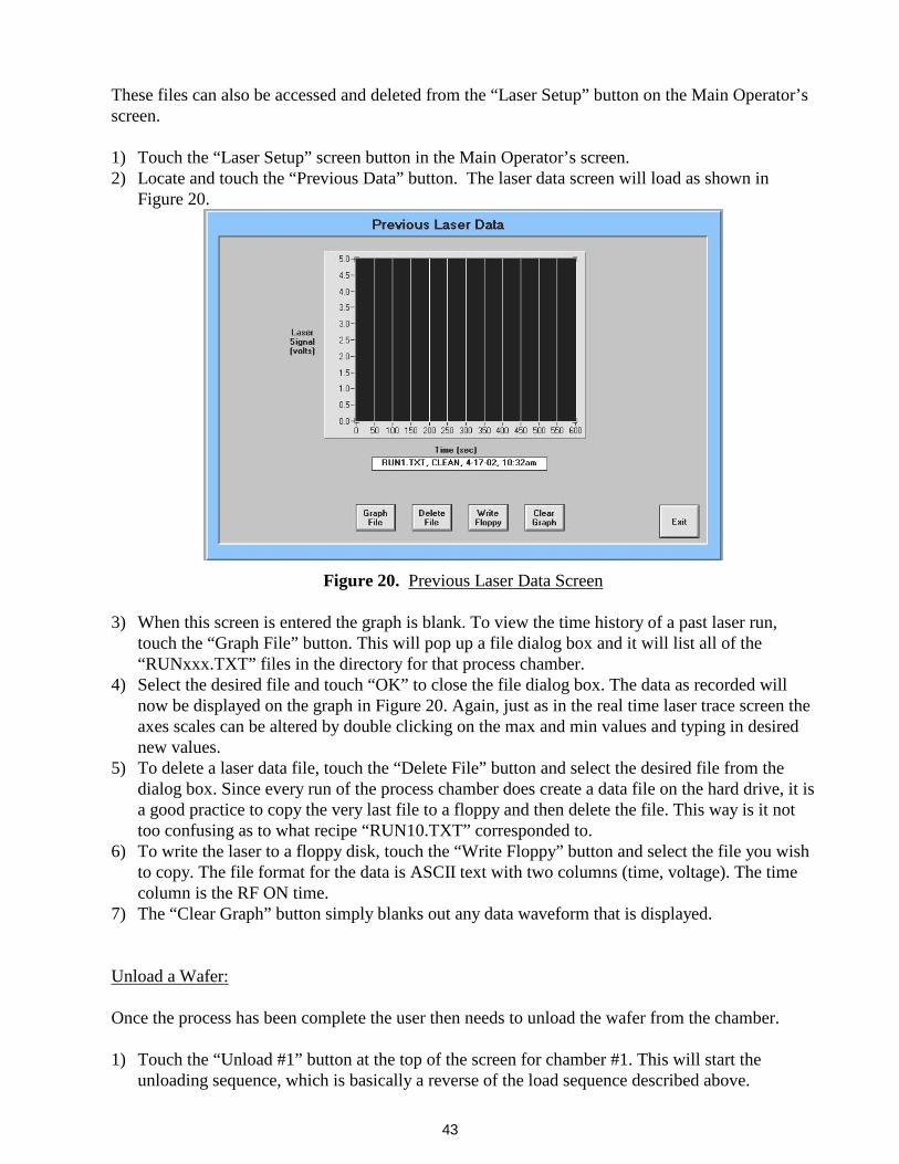
These files can also be accessed and deleted from the “Laser Setup” button on the Main Operator’s screen. 1) Touch the “Laser Setup” screen button in the Main Operator’s screen. 2) Locate and touch the “Previous Data” button. The laser data screen will load as shown in
Figure 20.
Figure 20. Previous Laser Data Screen
3) When this screen is entered the graph is blank. To view the time history of a past laser run, touch the “Graph File” button. This will pop up a file dialog box and it will list all of the “RUNxxx.TXT” files in the directory for that process chamber.
4) Select the desired file and touch “OK” to close the file dialog box. The data as recorded will now be displayed on the graph in Figure 20. Again, just as in the real time laser trace screen the axes scales can be altered by double clicking on the max and min values and typing in desired new values.
5) To delete a laser data file, touch the “Delete File” button and select the desired file from the dialog box. Since every run of the process chamber does create a data file on the hard drive, it is a good practice to copy the very last file to a floppy and then delete the file. This way is it not too confusing as to what recipe “RUN10.TXT” corresponded to.
6) To write the laser to a floppy disk, touch the “Write Floppy” button and select the file you wish to copy. The file format for the data is ASCII text with two columns (time, voltage). The time column is the RF ON time.
7) The “Clear Graph” button simply blanks out any data waveform that is displayed. Unload a Wafer: Once the process has been complete the user then needs to unload the wafer from the chamber. 1) Touch the “Unload #1” button at the top of the screen for chamber #1. This will start the
unloading sequence, which is basically a reverse of the load sequence described above.

44
2) No buttons are active except for the “Abort” button and this should only be used in case of a
malfunction during the process (such as wafer partially on the arm, etc…).
3) After the wafer has been returned to the load station platform the arm retracts and the load station transfer gate closes. At this point a dialog box appears asking the operator if he wishes to vent the load station or keep it under vacuum.
If the user wishes to perform a new process in a different chamber then he should NOT vent the load station and keep it under vacuum. Some processes are sensitive to air exposure to the wafer between process steps and maintaining vacuum is critical. If the user is done with the processing and wishes to extract the wafer then he needs to VENT the load station.
4) After the Unload sequence is complete, the “#1 Loaded” LED goes out and the “Unload #1” button is replaced with the “Load #1” button on the Main Operator’s screen.
Stand By Mode: The Stand By mode places the particular process module into a certain idle mode that is recommended for corrosive applications. The Stand By mode performs the following functions: 1) Places the chamber under vacuum (this is the normal state anyway). 2) Evacuates the corrosive plumbing by opening a vacuum valve inside the gas cabinet. 3) Cycle purges the corrosive plumbing with nitrogen inside the gas cabinet. This is pre-set a 5
cycles. 4) Leaves the corrosive plumbing filled with purge nitrogen. 5) For PECVD systems, the heater can be turned off or programmed to remain a the last
temperature set point. It is recommended that the heater be left on to at least 100deg C during the Stand By mode. This prevents undue thermal cycling on the showerhead from which deposits may flake off from.
6) While a chamber is in Stand By mode, all other operation buttons on the Main operator’s screen will be grayed out and inactive.
7) To exit the Stand By mode simply touch or click on the “Stand By” button again. The system will then evacuate the purge nitrogen from the corrosive plumbing and then be ready for normal processing.
If the chamber does have corrosive gases, such as Cl2, BCl3, HBr, or NH3, it is recommended that the operator places the machine in Stand By if the system will not be used again for some time. It is recommended that overnight and weekends the corrosive chambers be left in Stand By to extend the life of the corrosive plumbing components (mass flow controllers, gauges, regulators, etc…) If a certain chamber does NOT have any corrosive gases, then using the Stand By mode is not required.

45
VII) TYPICAL PROCESS CONDITIONS
Since the composition of semiconductor materials vary widely between companies; etch and deposition processes also vary. However, a good set of operating conditions can be developed by starting with the following typical conditions and varying them to suit your individual needs. For more information on plasma basics and other issues critical to processing, please visit the Trion Technology website at www.triontech.com. The following table is used to explain the basic trends involved with basic plasma processing of different materials.
Table 5. Process Trends
Increase in Process Variable Condition
Etch Rate Anisotropy Pressure
Pressure Increase Decrease ------- ICP Power Increase Decrease No effect RIE Power Increase Increase No effect Gas Flow Increase (slightly) No direct effect Increase
All etch recipes include an ICP, if you system does not include an ICP disregard the ICP power setting and keep all other variables constant. ETCH Processes
Table 6. Silicon Dioxide (SiO2) Etch Parameters
RIE Power 50 watts ICP Power 300 watts Pressure 50 mtorr Gases CHF3-47sccm, O2-3sccm
Etch Rate 1000Å/min
During a skeleton etch the following problems can occur: aluminum grass, polymer grass, gold grass and lifting. Photos of the different conditions are shown in the technical papers included in the manual. To avoid aluminum grass, remove the oxygen from the process recipe. Aluminum grass is formed by a combination of oxygen, fluorine and aluminum. If you want to learn more about aluminum grass please refer to included technical papers. To avoid polymer grass, lower the pressure to 25mtorr or below. Oxygen can also be added to remove the polymer grass although it is not recommended because the oxygen may cause aluminum grass to form. Gold grass occurs in package parts when the leads are not properly masked. The gold grass is caused by redeposition of sputtered gold. The only solution to this problem is to mask all the gold.

46
Lifting of aluminum lines is an indication of undercutting or an isotropic etch. This can be fixed a number of ways. The first solution is to lower the pressure. If this doesn’t solve the problem increase the RIE power and lower the ICP power. It is important to make sure the sample does not become hot. Ensure that the piece is in good contact with the aluminum chuck.
Table 7. Silicon Nitride (Si3N4) Etch Parameters
RIE Power 100 watts ICP Power 0 watts Pressure 250 mtorr
Gases SF 6-45sccm, O2-5sccm Etch Rate 2500Å/min
Any Fluorine containing gases can be used. Sulfur Hexafluoride is preferred due to its selectivity to SiO2. Increasing the ICP power will increase etch rates significantly.
Table 8. Polysilicon or TiW Etch Parameters
RIE Power 100 watts ICP Power 0 watts Pressure 300 mtorr Gases SF6-50sccm
Etch Rate 5000Å/min
Table 9.
Polyamide or Photo resist Etch Process
RIE Power 100 watts ICP Power 250 watts Pressure 150 mtorr Gases O2-45 sccm, SF6-5sccm
Etch Rate 10000Å/min
If you do not wish to etch into the passivation layer, the SF6 can be eliminated. In eliminating the SF6, the pressure needs to be lowered to 30 mtorr to ensure a clean etch.
Table 10. Aluminum Etch Parameters
RIE Power 75 watts ICP Power 0 watts Pressure 180 mtorr Gases BCl3-30 sccm, Cl2-30 sccm, CH4-2sccm
Etch Rate 1000Å/min
The CH4 is not necessary but ensures a smooth sidewall passivation on the aluminum. To increase the etch rate, increase the Cl2 amount. Be sure to rinse the wafer after processing because the residual chlorine will combine with moisture in the atmosphere to form small amounts of HCl.

47
PECVD Processes
Table 11. TEOS Based SiO2 Deposition Parameters
RIE Power (100kHz) 40 watts Pressure 1000 mtorr Gases TEOS-90 sccm, O2-75 sccm
Temperature 350 °C Dep Rate ~500 Å/min
Table 12. Silane Based SiO2 Deposition Parameters
RIE Power (100kHz) 60 watts Pressure 900 mtorr Gases SiH4=6 sccm, N2=140 sccm,
N2O=140 sccm Temperature 400 °C
Dep Rate ~1075 Å/min
Table 13. DES Based Si3N4 Deposition Parameters
RIE Power (100 kHz) 50 watts Pressure 600 mtorr Gases NH3=20 sccm, N2=180 sccm
DES=20 sccm Temperature 325 °C
Dep Rate ~450 Å/min
Table 14. Silane Based Si3N4 Deposition Parameters
RIE Power 40 watts Pressure 620 mtorr Gases SiH4=12, NH3=10 sccm
N2=200 sccm Temperature 350 °C
Dep Rate ~400 Å/min

48
VIII) SYSTEM MAINTENANCE
GENERAL This section will cover the general user maintenance that is required for the Oracle system. It will also give brief instructions on how to remove modules that need replacement or factory repair. In general, the Oracle CVT and process chambers have been designed to have critical modules easily removed and replaced. For each main section of the system, the module removal/installation procedures will be outlined in addition to periodic maintenance actions required to be taken by the customer. This section of the manual will also go over in detail the two main areas of the operation software that deals with maintenance. These are the “Hardware Setup” and “Maintenance” buttons on the Main Operator’s screen. MODULE REMOVAL, INSTALLATION and MAINTENANCE As described before, the Oracle system is comprised of the following main components: 1) CVT (Central vacuum transport)
The CVT contains the vacuum robot, lock pressure gauge, loading station platform and VAT brand transfer gate valves to seal off the process module chambers.
Maintenance:
Table 15. CVT Periodic Maintenance Schedule
Item Function How Often? Robot o-rings Clean or replace if torn or nicked. Every Two Years Robot bearings Clean and relubricate with Krytox-
type grease. Replace if rotation is still stiff.
Every Two Years
Pressure Gauge None. N/A Load Station Lift Pin O-rings Clean or replace if torn or nicked. Every One Year Gate Valve seal plate Clean or replace if seal is torn or
nicked. As needed (vacuum leak)
Static O-rings on lid, window insert, base plate etc…
Clean or replace if torn or nicked. As needed (vacuum leak)
The “As Needed” notation above means that the MTBF of these components is so very long it makes more sense to simply wait for the vacuum level to degrade before scheduling a replacement or cleaning for these seals.
Removal and Installation:
The maintenance personnel should follow the guidelines below for performing any component replacement or removal on the CVT.

49
Robot Service (including o-ring and bearing service):
a) In the “Maintenance” screen of the software, enter the “Manual Transport” screen. b) Close the vacuum valves for both the load station and the central load lock. c) Open the lock vent valve to bleed nitrogen into the CVT until you can hear the nitrogen
escaping from the lid. d) Close the vent valve. e) Ensure that all transfer gate valves are closed. f) Exit the software. g) Press the system’s EMO button on the console. h) Remove the bolts holding down the CVT lid and use two people to lift and remove the lid.
This lid is heavy and proper lifting techniques should be used.
The tool is now is a safe state to perform service on the robot arm assembly or it’s drive assembly. With the system powered down the arm can not move and cause pinch hazards, nor can the transfer gate valves move from the closed position. Follow the Trion robot service procedure document to instructions on servicing this component. Once the robot work has been complete and re-assembled, replace the lid and install the lid bolts. Do NOT tighten the bolts, simply thread them into the CVT body far enough that the lid can not be removed by hand. Then power up the tool by pressing the “Start” button on the main console. Pressure Gauge: For this gauge is there no user serviceable parts but if a new one is required, or the o-ring needs replacing, follow the steps below.
a) Use the “Maintenance” -> “Manual Transport” screen to vent the central load lock just as for robot service.
b) Once the CVT is vented remove a side panel on the CVT and locate the HPS Moducell gauge.
c) Disconnect the cable and remove the gauge from the bottom plate of the load lock. d) To install a new one, simply reverse the above procedure.
Load Station Lift Pins:
a. From the “Maintenance” -> “Manual Transport” screen, ensure that the load station transfer gate is close and that the Load Vacuum valve is close.
b. Open the Load Vent valve until the load station is at atmosphere (the central load lock can remain under vacuum for this procedure).
c. Remove the lift cylinder cover on the bottom of the load station by removing the single 5/16-24 nut.
d. Remove the three 8-32 bolts that connect each of the three lift pins to the triangle actuator plate.
e. Rotate the plate and cylinder slightly to enable the three pins to be pulled out of the bottom of the load station.
f. After replacing or cleaning the o-rings, reverse the procedure to re-install the pins. g. Do not fully tighten the 8-32 bolts. Get them finger tight and then exercise the pins from the
software screen. Make sure they travel smoothly. Once they are all in and smooth, remove

50
one 8-32 bolt at a time and apply a small amount of Lock-Tite to the threads. Then install the bolts finger tight again and re-check the smoothness of the motion.
Gate Seal and Static O-rings: When replacing or servicing any of these seals you must follow the same procedure for robot servicing. The system must be de-energized such that no robot arm motion or gate valve motion can endanger the maintenance personnel.
2) Equipment Console
Maintenance: This includes the host computer, main AC electrical distribution, RF tuning switch controls and the computer switch. None of these components will require periodic maintenance but if servicing is required please follow the general guidelines below. Removal and Installation: Computer: a. Exit the software. b. Move to the rear of the equipment console and locate the back of the computer. Disconnect
the power cord from the computer. This will shut any vacuum valves in the CVT but the individual process chambers will still be up.
c. Disconnect the various serial and instrumentation cables from the rear panel of the computer. Pay attention to the locations where each cable goes.
d. Return to the front of the console and remove the four bolts holding the computer into the rack rails.
e. Pull the computer out the front of the console. f. To re-install, simply reverse the removal procedure and power up the system.
There is not much to replace inside the computer, however at times memory or CPU fans can go bad and need replacing.
AC Distribution:

51
ONLY TRION TECHNOLOGY PERSONNEL SHOULD EVER WORK ON INTERNAL COMPONENTS TO THIS MODULE.
The AC Distribution module contains two basic components, the breakers and the AC relays. Neither of these require any period maintenance. When a failure occurs, notify Trion Technology and steps will be taken to get it repaired (depending upon warranty or service contract status).
a. Exit the software b. Press the console “EMO” button to power down the entire tool. c. Locate the power cord coming from the facility wall to the rear of the AC distribution
and disconnect the power. This might entail either unplugging the power cord or shutting off an house panel breaker. In either case, make sure that proper Lockout-Tagout procedures are followed.
d. Disconnect all cables and cords from the rear of the AC distribution, paying attention to the locations where they came from.
e. At the front of the console, remove the four bolts on the rack rail and pull the AC distribution forward and out.
f. Once parts have been replaced then re-install in the reverse order as removal. When everything has been bolted in and plugged in, then the main power disconnect can be turned back on (or the cord plugged back in) and the “Start” button can be pressed to power up the Oracle.
The tuning switch controls and computer switch can be removed without powering down any part of the system. The rack rails bolts at the front of the console simply need to be removed and then these parts can be pulled forward for service.
3) Process Module Each process module consists of the following main sub-assemblies; chamber plenum, computer, AC distribution, ICP, RF generator(s), turbo pump. Please follow the maintenance and removal/installation procedures for each of these components listed below. Maintenance:
Table 16. Chamber Periodic Maintenance Schedule
Item Function How Often? Chamber Appropriate Plasma clean. This is
different for each process, consult the Trion process support personnel.
At least once a day
Chamber walls, lid and chuck surface
Physical clean using DI water and Scotch-Brite pad. Wipe clean with IPA after.
At least once a month
All static O-rings and lift pin O-rings. This includes the chamber plenum assembly and the ICP assembly.
Clean or replace if torn, nicked or etched.
Every Year

52
Turbo pump oil (if applicable) Drain and dispose of old oil. Replace with new oil of proper grade. Consult the turbo pump manufacturer’s manual for correct oil type and grade.
Every Year
The other components listed do not require any periodic maintenance. Removal and Installation: RF Generator
The RF Generator is a self contained unit and should only be worked on by trained personnel. In the event of failure, disconnect the unit and send it to Trion for repair following the procedure below.
a. Abort any currently running process from the host computer screen. b. Locate the RF generator on the process module and unplug its power cord from the AC
distribution. c. Disconnect the control cable from the generator. d. For the RFG3001 models, turn off the cooling water and disconnect the cooling water lines
from the back of the generator. Be careful to wipe up any water that happens to leak onto the floor.
e. Pull the generator out the rear of the process module. f. In the advent of shipping the generator out for repair, make sure that it is securely packed in a
suitably strong box. Then obtain an RMA number from Trion Technology before shipping it.
AC Distribution This unit is located on the shelf of the process module and may need to be replaced in the advent of failure. To remove, follow the steps below.
a. Abort any running process on this chamber from the host computer screen. b. Locate the 3-pole circuit breaker on the console for that process chamber. c. Turn off this circuit breaker. d. At the rear of the process module, disconnect the incoming power cord to the AC distribution. e. Disconnect all other cords and cables from the unit paying attention to their location. f. Unbolt the AC distribution and slide it out the rear of the shelf. g. To install a new or repaired unit, follow the reverse of the above procedure.

53
Computer This unit is bolted to the front uprights near the transfer gate valve.
a. Abort any running process on this chamber from the host computer screen. b. Locate the AC distribution on the process module’s shelf and turn off the circuit breaker there. c. Disconnect the power cable from the side of the chamber’s computer. d. Disconnect all other instrumentation cables paying attention to where they are located. e. Loosen the four 13mm nuts at the corners of the computer mounting plate. Do NOT entirely
remove these nuts, only loosen them. f. Grab the computer and wiggle it until you can pull it out of the frame and then carefully remove
it out the rear of the process module. Be careful remove any cables or other hardware that may impede removal.
g. Reverse the procedure to re-install the computer. ICP
Residual traces of process gases and byproducts may still be present in the chamber and ICP even after plasma clean processes. When removing or servicing the ICP maintenance personnel must wear gloves.
a. From the “Maintenance” screen on the main computer, locate the “Vent Chamber #x” button that corresponds to the chamber requiring service.
b. Run this vent procedure until the chamber is at atmosphere. c. Return to the process module and locate the ICP assembly on top of the chamber. d. Shut off the cooling water supply and disconnect the cooling water lines. Cap off these lines to
prevent water from spilling onto the floor. e. Run a ¼” tube between the two water fittings on the ICP to prevent water from leaking out of
the ICP during servicing. f. Locate the RF power supply and unplug it from the AC distribution on the shelf. g. Disconnect the RF coax cable at the ICP. h. Disconnect the matching network control cable at the ICP. i. Remove the two ¼-20 bolts that hold the hinge brackets to the chamber body. j. You may now lift the ICP assembly off of the chamber to a bench for service. This is a heavy
unit and personnel are required to follow proper lifting techniques. k. To re-install, simply follow these steps in reverse.
Turbo
54
a. Locate the turbo power supply bolted to the inside of the process module frame. Turn off the power supply (the turbo pump will begin to spin down).
b. From the host computer vent the process chamber from the “Maintenance” screen. c. Turn off the roughing pump to that chamber. This may be done from the front console with the
single pole circuit breaker labeled “Pump” for that chamber. d. Allow the turbo to spin down to a stop. This may take 5 to 10 minutes. e. While waiting, turn off the cooling water to the turbo and disconnect the water lines. Again, cap
off the supply and return lines and be careful of any spilled water. f. Disconnect the turbo power cable. g. After the pump has stopped, disconnect the vacuum valve at the exit flange of the turbo pump.
This area may still be under vacuum so slowly break the vacuum seal as you remove the valve. h. With another person supporting the turbo pump, remove the four 8mm bolts and claw clamps
that hold the pump up to the gate valve. i. Slowly lower and remove the pump from the system. Make sure the inlet flange is covered so
that no dirt or foreign objects can enter the turbo while it is on the bench. j. Re-install the turbo in the reverse order. k. After physically installing the turbo and re-connecting all power and instrument cables, turn on
the main roughing pump. l. Then use the host computer to rough down the chamber. After the chamber has roughed down
and there is no vacuum leaks, turn the turbo power supply back on. m. Wait until the pump is at full speed and then the system is ready for use.
Plenum Assembly This assembly contains the RF matching network and chuck and is bolted directly to the bottom of the chamber. On PECVD systems this also includes the heater and heater control relay circuit. Only trained Trion Technology personnel should work on these units, but the procedures and precautions below should be followed. Precautions: Trace amounts or organic and fluorinated compounds may be present in the reactor after plasma cleaning. The physical cleaning of the chamber should be performed in a ventilated room. Gloves and eye protection should be worn.
GLOVES MUST BE WORN BY MAINTENANCE PERSONNEL! 1. Run the preprogrammed plasma CLEAN process. 2. Vent the chamber to atmosphere and open the lid.
55
3. Scrub any hard to remove deposits with an abrasive pad. 4. Wipe out the chamber with DI water on a chem wipe. 5. Wipe out the chamber with Isopropyl Alcohol on a chem wipe. 6. Close the lid and rerun the CLEAN process again. Any gloves and wipes used may be contaminated with IPA and/or etch or deposition by-products and should be disposed of in accordance with local regulations. RIE RF MATCHING NETWORKS
The matching network can contain high voltage and RF. Make sure that all power to the process module is shut off and the RF coaxial cable in disconnected from the matching network inlet. PECVD Heated Chuck
The chuck may still be at high temperature and care should be taken in working inside the chamber or on the heated assembly itself. To remove the plenum assemblies from the chambers, follow the instructions below.
a. Vent the chamber b. Turn off power to the process module from the console control. c. Remove ICP or standard flat lid from chamber. Again, use gloves when working on process
exposed components. d. Remove the turbo pump (if applicable – follow the above procedure for removing this
component). e. Shut off cooling water to the plenum assembly and disconnect the coolant lines. Loop tubing
between inlet and outlet to prevent water from spilling out of the assembly during maintenance. f. Disconnect all cables and power cords to the plenum assembly. g. Remove the four large 12mm bolts that hold down the chamber body to the frame. h. Remove the two 8mm hex bolts that clamp the chamber to the transfer gate valve. i. Using a second person, lift out the chamber and plenum assembly from the frame and remove
to a work bench. j. Placing a protective cloth on the working surface, place the chamber upside down so that the
plenum assembly is on the top.
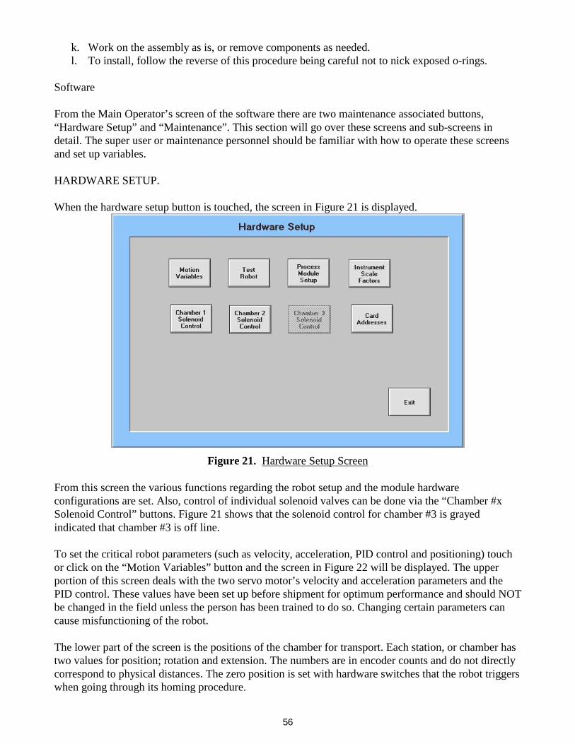
56
k. Work on the assembly as is, or remove components as needed. l. To install, follow the reverse of this procedure being careful not to nick exposed o-rings.
Software From the Main Operator’s screen of the software there are two maintenance associated buttons, “Hardware Setup” and “Maintenance”. This section will go over these screens and sub-screens in detail. The super user or maintenance personnel should be familiar with how to operate these screens and set up variables. HARDWARE SETUP. When the hardware setup button is touched, the screen in Figure 21 is displayed.
Figure 21. Hardware Setup Screen
From this screen the various functions regarding the robot setup and the module hardware configurations are set. Also, control of individual solenoid valves can be done via the “Chamber #x Solenoid Control” buttons. Figure 21 shows that the solenoid control for chamber #3 is grayed indicated that chamber #3 is off line. To set the critical robot parameters (such as velocity, acceleration, PID control and positioning) touch or click on the “Motion Variables” button and the screen in Figure 22 will be displayed. The upper portion of this screen deals with the two servo motor’s velocity and acceleration parameters and the PID control. These values have been set up before shipment for optimum performance and should NOT be changed in the field unless the person has been trained to do so. Changing certain parameters can cause misfunctioning of the robot. The lower part of the screen is the positions of the chamber for transport. Each station, or chamber has two values for position; rotation and extension. The numbers are in encoder counts and do not directly correspond to physical distances. The zero position is set with hardware switches that the robot triggers when going through its homing procedure.

57
The rotation and extension position tolerance values should be on the order of 30 counts. Too low a value will cause the software to stall out while the robot is trying to match the set position. Too high a value of tolerance will cause the arm to stop too soon and not properly transfer the wafer into the correct position. The “Home Timeout” value should be large enough to allow the robot to home from the furthest point away from the home positions. This is about 3 to 4 minutes. In general, all of the data on this screen will be properly set up upon the system installation by the Trion service technician. However, in the event that some slight tweaking is required to better place a wafer into a particular chuck, then the maintenance personnel should be familiar with this screen.
Figure 22. Robot Setup Screen The “Test Robot” button in figure 21 leads to a screen that allows the user to exercise each servo motor. This screen should NOT be used any longer since similar functions exist in the “Maintenance” screen and this will be described in detailed later. The “Process Module Setup” button on the Hardware Setup screen is one of the most important menus for the tool. Once touched or clicked on, Figure 23 is shown. In the upper part of this screen there are three large clusters of variables labeled “Chamber #1 Setup”, “Chamber #2 Setup” and “Chamber #3 Setup”. The variables listed in these clusters should correspond to the hardware that is actually installed each of the three process chambers. The lower portion of the screen shows other system variables that need to be set correctly for proper operation. Again, all of these data fields will be set up upon system installation. The com ports need to be configured correctly so that the proper chambers are connected to the right serial port. The “Transfer Press (mT)” and “Lock Base Pressure (mT)” need to be set to the same value

58
and this should be about 100-300mTorr. This is the pressure at which the load station and load lock need to get down to before the process chamber’s transfer gate valve will open. The “Pin Delay (ms)” is a time delay after the chamber lift pins actuate before the next step in the load/unload sequence is executed. This should be set on the order of 500 to 1000 ms. The “Purge Delay (ms)” is no longer used and should be set at 0.
Figure 23. Process Module Setup Screen
The “Base Pressure” value is that pressure at which the process chamber must get to before transfer can occur. It is also the pressure at which recipe processing can occur at. If this value is set too low, then transport or process errors will occur. The default value is 100mT. The “Lock Pumpdown Time (s)” is the pump down time for the load station when loading a wafer. This should be on the order of 20 to 40 seconds. The “Lock Vent Time (s)” is the amount of time the load station’s vent valve is opened to bring it to atmosphere. This value is determined by the vent gas pressure and can be adjusted as needed. The load station should not vent too quickly (less than 15 seconds) as this requires high vent gas flow and particle generation. From the Hardware Setup screen again, the “Instrument Scale Factors” button leads to the display in Figure 24. Again, each chamber has a variable cluster containing the pertinent scale factor information for its hardware. These scale factors instruct the software how to interpret the analog voltages coming into the I/O board from the instrumentation on the system. For example, chamber #1 has a 2Torr maximum range Baratron capacitance manometer pressure gauge. For the software to correct scale the analog signal to display actual mTorr, we enter 2000 mT (or 2T) into the data field for the pressure set and read values.

59
Likewise the other instrumentation is setup properly upon the system installation. However, if different equipment is changed out at a later date (an MFC for example) then these values would need to be set correctly. For the process gases the data entered into the data fields in Figure 21 must correspond to the maximum flow of the actual process gas flowing through that particular mass flow controller. For example, Chamber #1 has CF4 flowing through MFC #1. By looking into the gas cabinet and finding the first mass flow controller, we would find that it is a 250sccm N2 calibrated controller. Thus we need to convert from nitrogen to CF4 using the flow factors supplied by the MFC manufacturers. Table 9 below summary the most common gas conversion factors found in the Trion Technology Oracle system.
Figure 24.
Scale Factor Setup Screen
Table 17.
Typical Process Gas Flow Conversion Factors
Process Gas Chemical Symbol
Flow Factor to Nitrogen
Ammonia NH3 0.79 Argon Ar 1.40 Boron Trichloride BCl3 0.44 Carbon Tetrafluoride (Freon-14) CF4 0.43 Fluoroform (Freon-23) CHF3 0.51 Helium He 1.40 Hexafluoroethane (Freon-116) C2F6 0.25 Hydrogen H2 1.00 Hydrogen Bromide HBr 1.03 Hydrogen Chloride HCl 1.02 Methane CH4 0.75

60
Nitrogen Trifluoride NF3 0.49 Nitrous Oxide N2O 0.71 Oxygen O2 0.98 Process Gas Chemical Symbol Flow Factor to Nitrogen Silane SiH4 0.60 Silicon Tetrachloride SiCl4 0.30 Sulfur Hexafluoride SF6 0.27
In our example, to calculate the maximum flow of CF4 through the 250sccm N2 MFC, use the following formula: Max Flow CF4 = 250sccm N2 * (0.43 N2/CF4) = 108 sccm CF4 This number would then be entered into the data field for gas #1 shown in Figure 24. The data fields for the Temperature only need to be entered if the process chamber is a PECVD system. Here the low value should be zero and the high value is 500deg C. There are special sensors that have large temperature ranges and these will be set up before the system ships. Back to the Hardware Setup screen in Figure 21, the “Card Address” button should not be touched since these I/O card values should never be changed in the field. If they are, then the system will simply not function properly or at all. The Solenoid Control buttons for each process chamber brings up the following screen for controlling the individual valves in the system.
Figure 25. Solenoid Control Screen

61
When this screen is entered, all the valves close by default and the correspond control boxes shown in Figure 25 are white. The “Roughing Valve” control box has been touched to re-open the roughing valve on the chamber. WARNING: This screen must be used only by experienced personnel since there are no software controls preventing incorrect valve operation. This screen is most useful for venting the chamber or cycling the corrosive purge valves for a bottle or MFC change. When you exit this screen the software will automatically close all valves and then open the chamber roughing valve by default. If you have a turbo pump installed on your system and you vented the chamber, you need to first isolate the turbo pump before roughing down the chamber. If you are unsure of how to use this screen, contact a Trion Technology technician and he can walk you through the correct procedures. MAINTENANCE SCREEN. From the Main Operator’s screen the “Maintenance” button will bring up the following display.
Figure 26. Maintenance Panel This panel allows the user to vent and then rough down the process chambers and load or unload wafers from the chambers. However, the most useful item on this screen is the “Manual Transport” screen. There are limited safeguards in this screen so it is important that only experienced users operate the tool in this mode. Figure 27 shows the “Manual Transport” screen and the various transfer stations. Each station has the following controls: Large Station button (labeled as “Chamber #1”, “Chamber #2”, “Chamber #3”, “Load Station”), Transfer Gate button (labeled as “Gate”) and Lift Pins button (labeled as “Pins”). The stations also have an indicator bar, which displays the current state of the transfer gate valve; red means

62
the valve is closed and green means the valve is open. The stations at the chambers also have a chamber pressure display. The units for pressure display are mTorr.
Figure 27.
Manual Transport Screen
The robot motors current positions are displayed in the “Rotation Position” and “Extension Position” data fields. The robot arm is rotate to a specified location by touching or clicking on the large station button. The gate is opened and closed with the “Gate” buttons. The robot arm can be extended into a chamber of the load station by touching the “Extend” button. Likewise the arm is retracted using the “Retract” button. The two robot motors can be re-initialized by touching the “Home Rotate” or “Home Extend” buttons. NOTE: ensure that the arm is fully retracted before homing the rotation motor. The “Stop Motion” button can be used to immediately halt all robot motion. The control buttons on the left side of the screen are used for controlling the various vacuum and vent valves on the load lock and load station. This screen is intended to be used in case of automatic load or unload sequence malfunction and can be utilized to manually transfer a wafer. This screen is also used to teach, or program the station rotation and extension positions. Again, make sure only trained personnel who understand all of the functions in this screen have access to it.

63
IX) APPENDIX A The following attached pages show the various electrical and system schematics for the CVT and the process module chambers.