tricky??? you have a jug of milk, and you need to measure out just one cup. how do you do this if...
TRANSCRIPT

Tricky???
You have a jug of milk, and you need to measure out just one cup. How do you do this if you only have a three-cup measuring container and a five-cup container?
The ages of a father and son add up to 66. The father's age is the son's age reversed. How old could they be?
You are standing in front of a room with one light bulb inside of it. You cannot see if it is on or off. Outside the room there are 3 switches in the off positions. You may turn the switches any way you want to. You stop turning the switches, enter the room and know which switch controls the light bulb. How?
Adapted from Angel: Interactive Computer Graphics 5E © Addison-
Wesley 20091

Problem
1. A, B, C, D and E play a game of cards. A says to B, "If you give me three cards, you will have as many as E has and if I give you three cards, you will have as many as D has." A and B together had 10 cards more than what D and E together have. If B has two cards more than what C has and the total number of cards be 133, how many cards does B have?
Adapted from Angel: Interactive Computer Graphics 5E © Addison-
Wesley 20092

Problem
Count the number of squares in the given figure.
Adapted from Angel: Interactive Computer Graphics 5E © Addison-
Wesley 20093

Problem
There are some houses in a street back to back .And the house behind 10 is 23.
How many houses are there in the street?
Adapted from Angel: Interactive Computer Graphics 5E © Addison-
Wesley 20094

Problem
A batsman average was 15. At last innings he took 23 runs, then his average became16.how many runs he should have scored to make his average 18?
Adapted from Angel: Interactive Computer Graphics 5E © Addison-
Wesley 20095
Problem
A secret can be told only to 2 persons in 5 minutes .the same person tells to 2 more persons and so on . How long will it take to tell it to 768 persons ?
Adapted from Angel: Interactive Computer Graphics 5E © Addison-
Wesley 20096

Adapted from Angel: Interactive Computer Graphics 5E © Addison-Wesley 2009
7
Computer Graphics and Visualization (06 CS 65)
Dept of Computer Science and Engineering
Srinivas School of Engineering, Mukka

Chapter 1
Adapted from Angel: Interactive Computer Graphics 5E © Addison-
Wesley 20098
What is Computer Graphics?

Objectives
In this lecture, we explore what computer graphics is about and survey some application areas
We start with a historical introduction
Adapted from Angel: Interactive Computer Graphics 5E © Addison-
Wesley 20099

Computer Graphics
Computer graphics deals with all aspects of creating images with a computer– Hardware– Software– Applications
Adapted from Angel: Interactive Computer Graphics 5E © Addison-
Wesley 200910

Example
Where did this image come from?
What hardware/software did we need to produce it? Adapted from Angel: Interactive
Computer Graphics 5E © Addison-Wesley 20091
1

Preliminary Answer
Application: The object is an artist’s rendition of the sun for an animation to be shown in a domed environment (planetarium)
Software: Maya for modeling and rendering but Maya is built on top of OpenGL
Hardware: PC with graphics card for modeling and rendering
Adapted from Angel: Interactive Computer Graphics 5E © Addison-
Wesley 200912
Some interesting applications
Training pilots with simulated airplanes Generating graphical displays of virtual
environment in real time Movies! Massive multiplayer games!
Adapted from Angel: Interactive Computer Graphics 5E © Addison-
Wesley 200913
Different ways to obtain images
Handwritten Photography Computer graphics!
Adapted from Angel: Interactive Computer Graphics 5E © Addison-
Wesley 200914
Application areas of Computer Graphics
Display of information Design Simulation and animation User interfaces
Adapted from Angel: Interactive Computer Graphics 5E © Addison-
Wesley 200915

Display of information
A medium to convey info among people– More than 4000 yrs ago, babylonians displayed floor plans of buildings on
stones– More than 2000 yrs ago, Greeks conveyed their architectural ideas
graphically– Today same info generated by architects using computer-based drafting
systems Maps can be developed and manipulated in real-time over internet Detecting security threats using bio-informatics Medical imaging – CT scan, MRI scan, PET scan etc generate 3-D
data & is subjected to algorithmic manipulation to provide useful info Fluid flow, molecular biology and mathematics
Adapted from Angel: Interactive Computer Graphics 5E © Addison-
Wesley 200916

Design
Engineering and arch concerned with design– Cost effective and esthetic solution– Satisfying specifications– Iterative process
Graphic tools in Computer-Aided Design(CAD)– In mech, arch, VLSI ckts, animations
Having tools to generate different images of same objects at different stages of design process
Adapted from Angel: Interactive Computer Graphics 5E © Addison-
Wesley 200917

Simulation and animation
Sophisticated images in real time Training of pilots
– Increase safety and reduce training expenses Designing robots, planning its path, simulating its behavior
in complex environments Animation in television, motion pictures and advertising
industries– Entire animated movies using computers
Can generate photorealistic images by a computer– Difficult to distinguish computer generated or computer-altered
images from a photograph! Adapted from Angel: Interactive Computer Graphics 5E © Addison-
Wesley 200918

Simulation and animation
Field of Virtual Reality(VR)– Human viewer equipped with a display headset that
allows to see separate images with right eye and left eye!– Body location and position tracked by the computer– Can act as part of a computer-generated scene
Can train a surgical intern to do an operation in this way! Or an astronaut might be trained to work in a weightless
environment!
Revenue from video games has surpassed revenue from commercial films!
Adapted from Angel: Interactive Computer Graphics 5E © Addison-
Wesley 200919

User interfaces
Interaction with computers using a visual paradigm– Windows, icons, menus and a pointing device
X windows system, microsoft windows, Macintosh OS X etc
Internet explorers such as Firefox and IE– We often forget that we are working with computer
graphics UI for modeling geometric objects
Adapted from Angel: Interactive Computer Graphics 5E © Addison-
Wesley 200920

A graphics system
Has all components of a general-purpose computer 5 major elements
– Input devices– Processor– Memory– Frame buffer– Output devices
Although all are present in a standard computer(except frame buffer), it is the way each element is specialized for computer graphics that matters
Adapted from Angel: Interactive Computer Graphics 5E © Addison-
Wesley 200921

Basic Graphics System
Adapted from Angel: Interactive Computer Graphics 5E © Addison-
Wesley 200922
Input devices
Output device
Image formed in FB
Pixels and Frame Buffer
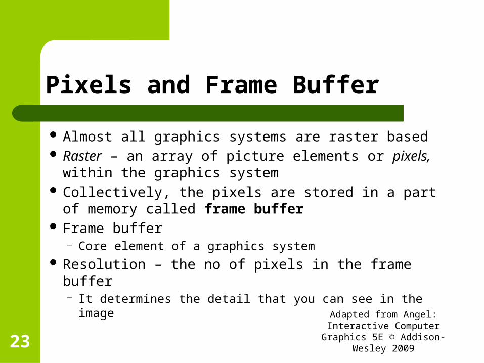
Almost all graphics systems are raster based Raster – an array of picture elements or pixels,
within the graphics system Collectively, the pixels are stored in a part of
memory called frame buffer Frame buffer
– Core element of a graphics system Resolution – the no of pixels in the frame buffer
– It determines the detail that you can see in the imageAdapted from Angel: Interactive
Computer Graphics 5E © Addison-Wesley 200923

Pixels
Adapted from Angel: Interactive Computer Graphics 5E © Addison-
Wesley 200924
Image of a Cat using pixels
Detail of area around one eye showing individual pixels

Frame buffer continued..
Depth ( or precision ) of frame buffer– No of bits that are used for each pixel– Determines properties like how many colors can be
represented etc– 1 bit deep, then two colors– 8-bit deep, then 256 colors– In full color systems, there are 24( or more) bits per
pixel. Can display sufficient colors to represent most images realistically
Also called as true-color or RGB-color systemsAdapted from Angel: Interactive
Computer Graphics 5E © Addison-Wesley 200925

Continued..
Frame buffer is implemented with special types of memory chips– Enables fast redisplay of contents of frame buffer
In a very simple system, frame buffer holds only colored pixels that are displayed on the screen
In most systems, frame buffer also holds info such as depth info needed for creating images from 3-D data– In such systems, frame buffers comprise multiple buffers
Adapted from Angel: Interactive Computer Graphics 5E © Addison-
Wesley 200926

Processor
To take specifications of graphical primitives ( lines, circles, polygons etc) generated by application programs and to assign values to the pixels in the frame buffer that best represent these entities
Conversion of geometric entities to pixel colors and locations in the frame buffer is known as rasterization or scan conversion
Now a days, special purpose graphics processing units(GPUs) are used– Custom tailored to carry out specific graphics functions– GPU can be on mother board or on a graphics cardAdapted from Angel: Interactive
Computer Graphics 5E © Addison-Wesley 200927
Output devices
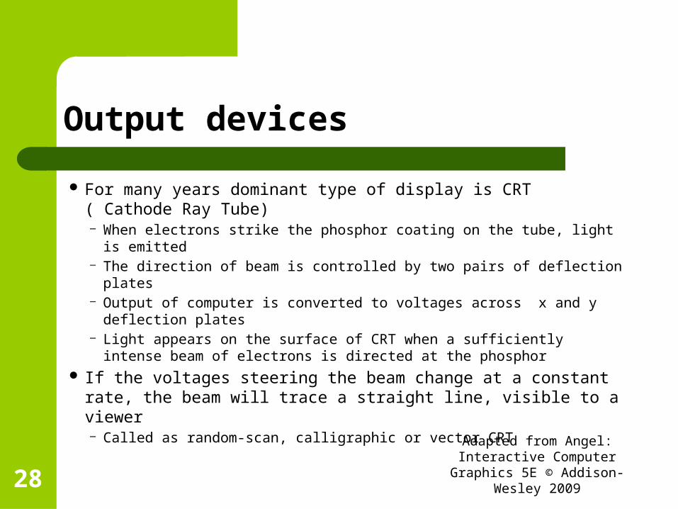
For many years dominant type of display is CRT ( Cathode Ray Tube)– When electrons strike the phosphor coating on the tube, light is
emitted– The direction of beam is controlled by two pairs of deflection plates– Output of computer is converted to voltages across x and y
deflection plates– Light appears on the surface of CRT when a sufficiently intense
beam of electrons is directed at the phosphor If the voltages steering the beam change at a constant rate,
the beam will trace a straight line, visible to a viewer– Called as random-scan, calligraphic or vector CRT
Adapted from Angel: Interactive Computer Graphics 5E © Addison-
Wesley 200928

CRT
Can be used either as a line-drawing device (calligraphic) or to display contents of frame buffer (raster mode)
Adapted from Angel: Interactive Computer Graphics 5E © Addison-
Wesley 200929

Contd…
A typical CRT will emit light only for a short time– Few millisecs
For a human to see a steady, flicker free image, the same path must be retraced or refreshed, by the beam at a sufficiently high rate, called refresh rate– Modern displays have refresh rate of about 85 Hz
Raster system – system displays them as points on the surface of display in 2 ways– Progressive display – pixels are displayed row by row at the refresh
rate– Interlaced display – odd rows and even rows are refreshed alternately
Adapted from Angel: Interactive Computer Graphics 5E © Addison-
Wesley 200930

Shadow-mask CRT – colored CRT
Adapted from Angel: Interactive Computer Graphics 5E © Addison-
Wesley 200931
Shadow mask, a metal screen with small holes, to ensure that an electron beam excites only phosphors of the proper color

Generic flat-panel display
Adapted from Angel: Interactive Computer Graphics 5E © Addison-
Wesley 200932
LEDLCDPlasma panels

Flat panel monitors
Inherently raster LEDs ( light emitting diodes )
– Middle panel contains light emitting diodes – can be turned on or off by the electrical signals sent to the grid
LCDs(liquid crystal displays)– The electrical field controls the polarization of the liquid crystals in
the middle panel Plasma panels
– Voltages on the grids energize gases embedded between the glass panels holding the grids
2 outside plates contain parallel grids of wires that are oriented perpendicular to each other– By sending electrical signals to proper wires in each grid, the
electrical field at a location, determined by the intersection of two wires, can be made strong enough to control corresponding element in the middle plate

Projection systems
Most of them are also raster devices Use a variety of technologies including CRTs
and DLP( Digital Light Projection )

Input Devices
Keyboard + one another input device– Like mouse, joystick or data tablet
Called as pointing devices– Allow user to indicate a particular location on the
display Game consoles – multiple buttons, joystick, dials
etc Games, CAD and virtual reality applications
– Need for 3-D location input– Laser range finders and acoustic sensors– Data gloves – sensors, computer vision systems

Objects and viewers
Object – exist in space independent of any image formation process and of any viewer– In graphics, we form objects by specifying the
positions in space of various geometric primitives (lines, points, polygons)
– In most graphic systems, a set of locations ( or vertices ) in space is sufficient to define ( or approximate) most objects. Ex., line, sphere

Imaging system
Every imaging system must provide means of forming images from objects
To form image we must have someone viewing our objects ( person, camera etc)
It is the viewer that forms the image of our objects In human visual system, image is formed at the
back of the eye, in a camera on a film plane Do not confuse objects and images

Every imaging system must provide a means of forming images from objects
Adapted from Angel: Interactive Computer Graphics 5E © Addison-
Wesley 200938
It is the viewer that forms the images of our objects
viewer can be a person, a camera or a digitizer

A camera system viewing image of a building
Adapted from Angel: Interactive Computer Graphics 5E © Addison-
Wesley 200939
Both object and viewer exist in 3-D worldBut the image that they define, on film plane, is 2-D
Light and images
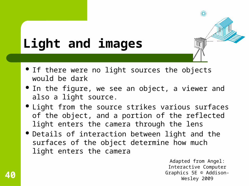
If there were no light sources the objects would be dark
In the figure, we see an object, a viewer and also a light source.
Light from the source strikes various surfaces of the object, and a portion of the reflected light enters the camera through the lens
Details of interaction between light and the surfaces of the object determine how much light enters the camera
Adapted from Angel: Interactive Computer Graphics 5E © Addison-
Wesley 200940
Light source
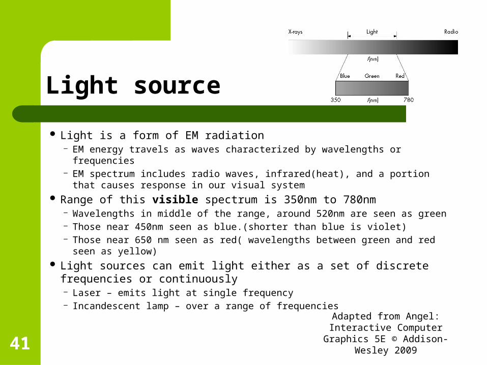
Light is a form of EM radiation– EM energy travels as waves characterized by wavelengths or frequencies– EM spectrum includes radio waves, infrared(heat), and a portion that
causes response in our visual system Range of this visible spectrum is 350nm to 780nm
– Wavelengths in middle of the range, around 520nm are seen as green– Those near 450nm seen as blue.(shorter than blue is violet)– Those near 650 nm seen as red( wavelengths between green and red seen
as yellow) Light sources can emit light either as a set of discrete frequencies or
continuously– Laser – emits light at single frequency– Incandescent lamp – over a range of frequencies
Adapted from Angel: Interactive Computer Graphics 5E © Addison-
Wesley 200941
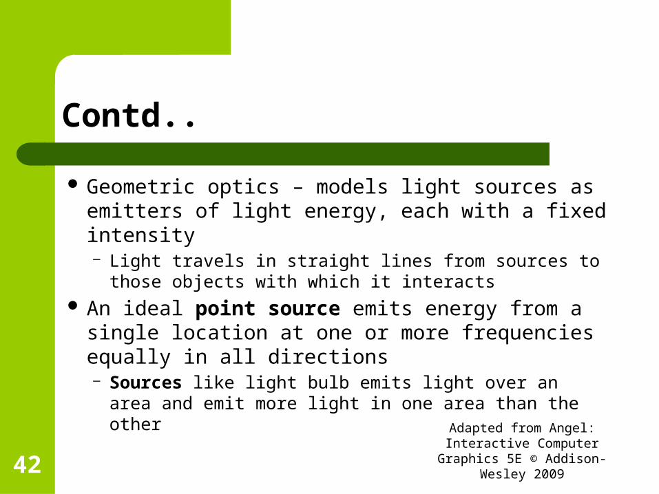
Contd..
Geometric optics – models light sources as emitters of light energy, each with a fixed intensity– Light travels in straight lines from sources to those
objects with which it interacts An ideal point source emits energy from a single
location at one or more frequencies equally in all directions– Sources like light bulb emits light over an area and emit
more light in one area than the other
Adapted from Angel: Interactive Computer Graphics 5E © Addison-
Wesley 200942
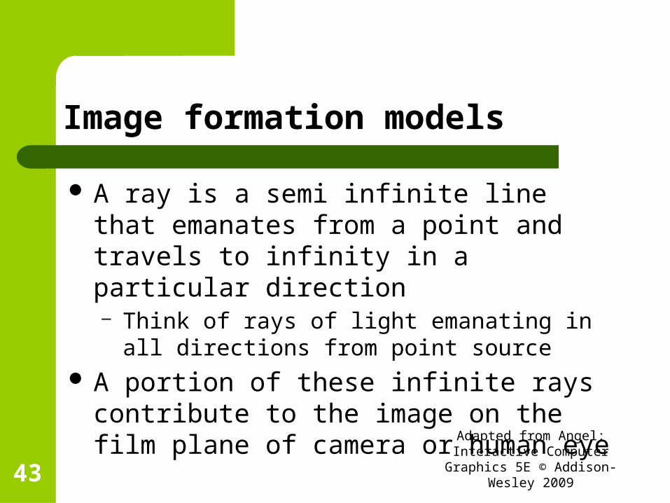
Image formation models
A ray is a semi infinite line that emanates from a point and travels to infinity in a particular direction– Think of rays of light emanating in all directions
from point source A portion of these infinite rays contribute to
the image on the film plane of camera or human eye
Adapted from Angel: Interactive Computer Graphics 5E © Addison-
Wesley 200943

Image formation models
Adapted from Angel: Interactive Computer Graphics 5E © Addison-
Wesley 200944

Contd…
If source is visible from camera, some of the rays go directly from the source through the lens of the camera and strike film plane
Most rays go off to infinity– Contribute nothing to the image
Rays striking objects can interact in a variety of ways– If surface is mirror, depending on orientation of the surface – enters
lens of camera and form images– Other surfaces scatter light in all directions– If surface is transparent, light ray from source can pass through it
and may interact with other objects, enter the camera, or travel to infinity without striking other surface
Adapted from Angel: Interactive Computer Graphics 5E © Addison-
Wesley 200945

Image formation techniques
Ray tracing– Not well suited for real-time computation
Photon mapping Radiosity
– Most important in computer graphics
Adapted from Angel: Interactive Computer Graphics 5E © Addison-
Wesley 200946
Imaging Systems
Two physical imaging systems– Pin hole camera– Human visual system
Adapted from Angel: Interactive Computer Graphics 5E © Addison-
Wesley 200947
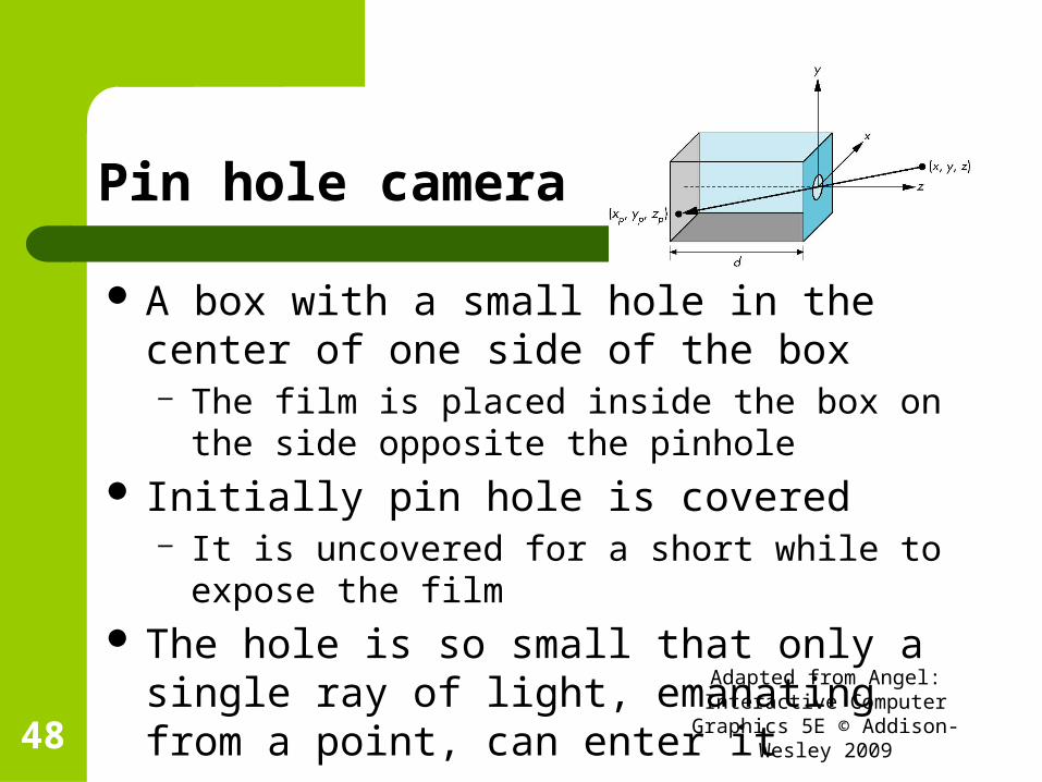
Pin hole camera
A box with a small hole in the center of one side of the box– The film is placed inside the box on the side
opposite the pinhole Initially pin hole is covered
– It is uncovered for a short while to expose the film The hole is so small that only a single ray of
light, emanating from a point, can enter itAdapted from Angel: Interactive
Computer Graphics 5E © Addison-Wesley 200948
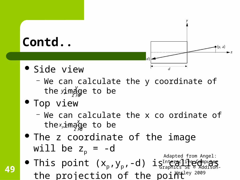
Contd..
Side view– We can calculate the y coordinate of the image to
be Top view
– We can calculate the x co ordinate of the image to be
The z coordinate of the image will be zp = -d
This point (xp,yp,-d) is called as the projection of the point (x,y,z) Adapted from Angel: Interactive
Computer Graphics 5E © Addison-Wesley 200949
dz
yy p /
dz
xxp /

Contd..
All points along the line between (x,y,z) and (xp,yp,-d) project to (xp,yp,-d)– We cannot go backward from a point in the image
plane to a point that produced it. Field, or angle, of view of our camera is the
angle made by the largest object that our camera can image on its film plane– If h is the height of the camera, angle of view θ is
Adapted from Angel: Interactive Computer Graphics 5E © Addison-
Wesley 200950d
h
2tan2 1
Contd…
Ideal pinhole camera has an infinite depth of field– Every point within its field of view is in focus, regardless of how far it is from the
camera Disadvantages
– Pinhole is very small – admits only a single ray of light – almost no light enters the camera
– The camera cannot be adjusted to have different angle of view By replacing the pinhole with a lens, we solve the two problems of the
pinhole camera– Lens gather more light– By picking a lens with proper focal length, we can achieve any desired angle of
view upto 1800
Physical lenses do not have infinite depth of field; not all objects in front of the lens are in focus
Adapted from Angel: Interactive Computer Graphics 5E © Addison-
Wesley 200951

The human visual system
Light enters the eye through the lens and cornea, a transparent structure that protects the eye
The iris opens and closes to adjust the amount of light entering the eye
The lens forms an image on a two-dimensional structure called the retina on the back of the eye
The rods and cones are light sensors and are located on the retina– They are excited by electromagnetic energy in the range of
350 to 780 nmAdapted from Angel: Interactive
Computer Graphics 5E © Addison-Wesley 200952

Contd..
The rods are low-level light sensors that account for our night vision and are not color sensitive– The cones are responsible for our color vision
The sizes of the rods and cones, coupled with the optical properties of the lens and cornea, determine the resolution of our visual system
Resolution is a measure of what size objects we can see– It is a measure of how close we can place two points and
still recognise that there are two distinct pointsAdapted from Angel: Interactive
Computer Graphics 5E © Addison-Wesley 200953

Contd..
The sensors in the human eye do not react uniformly to light energy at different wavelengths
There are 3 types of cones and a single type of rod
Whereas intensity is a measure of light energy, brightness is a measure of how intense we perceive the light emitted from an object to be– We are most sensitive to green light, and least
sensitive to red and blueAdapted from Angel: Interactive
Computer Graphics 5E © Addison-Wesley 200954
Contd…
Initial processing of light in the human visual system is based on same principles used by most optic systems– But the human visual system has a back end much more
complex that that of a camera or telescope The optic nerve is connected to the rods and cones in
an extremely complex arrangement that has many of the characteristics of a sophisticated signal processor
Final processing is done in part of brain called as visual cortex, where high level functions like object recognition are carried out
Adapted from Angel: Interactive Computer Graphics 5E © Addison-
Wesley 200955

The synthetic-camera model
We look at creating a computer-generated image as being similar to forming an image using an optical system– Called as synthetic-camera model
In the figure, we have– Objects and a viewer– Image formed on the film plane at the back of
camera
Adapted from Angel: Interactive Computer Graphics 5E © Addison-
Wesley 200956

Basic principles of image formation
The specification of the objects is independent of the specification of the viewer– So in graphics library, we need to have separate
functions for specifying the objects and viewer We can compute the image using simple
geometric calculations
Adapted from Angel: Interactive Computer Graphics 5E © Addison-
Wesley 200957

Equivalent views of image formation
Adapted from Angel: Interactive Computer Graphics 5E © Addison-
Wesley 200958
(a)Image formed on back of the camera(as in a pinhole camera)(b) Image plane moved in front of the camera
In a real camera, we flip the image to get the original orientation of the object. In our synthetic camera model, We avoid flipping by a simple trick

Imaging with the synthetic camera
We draw another plane in front of lens and work in 3-dimensions
We find image of a point on the object on the virtual image plane by drawing a line, called projector– From the point to the center of the lens, called as center of
projection– All projectors are rays emanating from the center of projection
The virtual image plane we have moved in front of the lens is called as the projection plane– The image of the point is located where the projector passes
through the projection planeAdapted from Angel: Interactive
Computer Graphics 5E © Addison-Wesley 200959

Imaging with a synthetic camera
Adapted from Angel: Interactive Computer Graphics 5E © Addison-
Wesley 200960
Projection plane(image is formed wherever projector passes through this plane)

Clipping window
We saw not all objects can be imaged onto the pinhole camera’s film plane. – The angle of view expresses this limitation
This limitation is expressed in front by placing a clipping rectangle or clipping window, in the projection plane– This rectangle acts as a window, through which a viewer, located at
the center of projection, sees the world Given
Location of center of projection Location and orientation of projection plane Size of clipping rectangle
– We can determine which objects will appear in the imageAdapted from Angel: Interactive
Computer Graphics 5E © Addison-Wesley 200961
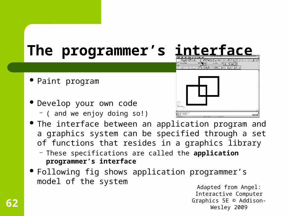
The programmer’s interface
Paint program
Develop your own code– ( and we enjoy doing so!)
The interface between an application program and a graphics system can be specified through a set of functions that resides in a graphics library– These specifications are called the application programmer’s
interface Following fig shows application programmer’s model of the
systemAdapted from Angel: Interactive
Computer Graphics 5E © Addison-Wesley 200962

Application programmer’s model of graphics system
He sees only API– Shielded from details of both hardware and software
implementation of graphics library Software drivers are responsible for interpreting
the output of API and converting these data to a form that is understood by particular hardware
The functions available through the API should match the conceptual model that the user wishes to employ to specify images
Adapted from Angel: Interactive Computer Graphics 5E © Addison-
Wesley 200963
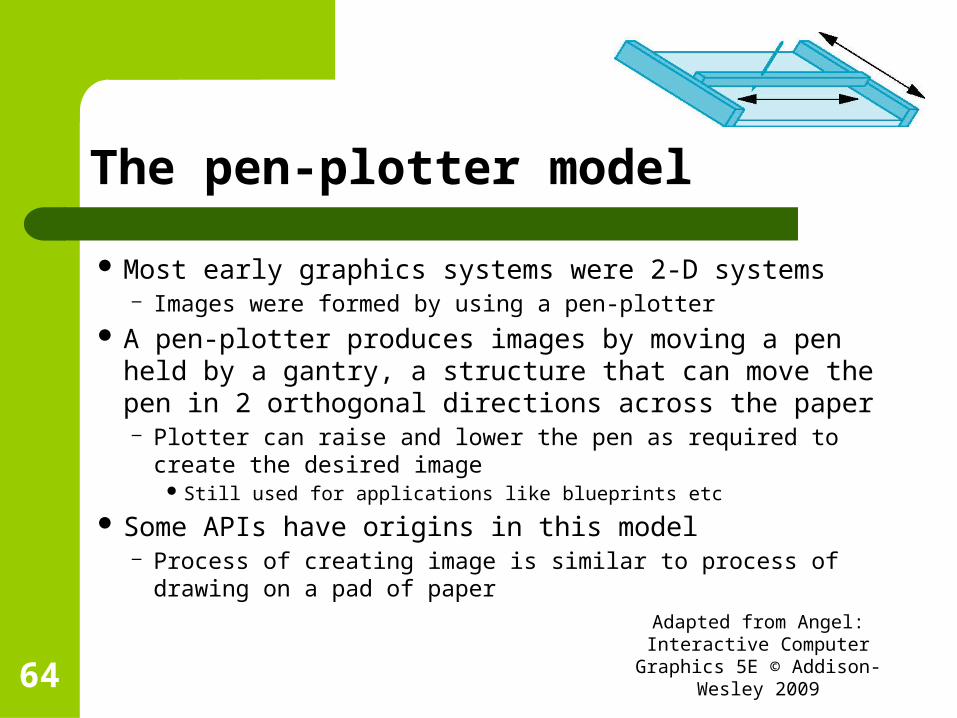
The pen-plotter model
Most early graphics systems were 2-D systems– Images were formed by using a pen-plotter
A pen-plotter produces images by moving a pen held by a gantry, a structure that can move the pen in 2 orthogonal directions across the paper– Plotter can raise and lower the pen as required to create the
desired image Still used for applications like blueprints etc
Some APIs have origins in this model– Process of creating image is similar to process of drawing on
a pad of paper Adapted from Angel: Interactive Computer Graphics 5E © Addison-
Wesley 200964

Contd…
We can describe such graphics systems with following drawing functions– moveto(x,y) – moves the pen to location (x,y) on paper
without leaving a mark– lineto(x,y) – moves the pen to location (x,y) and draws a
line from the old to the new location of the pen Add a few more options like initiation/termination
procedures and ability to change pens ( to alter drawing color or line thickness) – and we get a simple but complete graphics system
Adapted from Angel: Interactive Computer Graphics 5E © Addison-
Wesley 200965

Fragment of a program to draw a square in pen-plotter based APIs
moveto(0,0); lineto(1,0); lineto(1,1); lineto(0,1); lineto(0,0);
Adapted from Angel: Interactive Computer Graphics 5E © Addison-
Wesley 200966

What is the image obtained by below program segment?
moveto(0,0); lineto(1,0); lineto(1,1); lineto(0,1); lineto(0,0); moveto(0,1); Lineto(0.5,1.866); lineto(1.5,1.866); lineto(1.5,0.866); lineto(1,0); moveto(1,1); lineto(1.5,1.866);
Adapted from Angel: Interactive Computer Graphics 5E © Addison-
Wesley 200967

Answer
Adapted from Angel: Interactive Computer Graphics 5E © Addison-
Wesley 200968
A raster-based approach for 2-D model
Write pixels directly into frame buffer We can use a single function of the following
form– write_pixel(x,y,color);– x,y is the location of the pixel in the frame buffer– color gives the color to be written there
Such models used while writing algorithms for rasterization and processing of digital images
Adapted from Angel: Interactive Computer Graphics 5E © Addison-
Wesley 200969

Limitations of pen-plotter model in 3-D world
We need to produce the image of a 3-D object on our 2-D pad– Need to figure out where to place 2-D points corresponding to points on our
3-D object. These 2-D points are the projections of points in 3-D space
– Need to apply trigonometry to determine projections Its preferable to use an API, that allows users to work directly in the
domain of the problems and use computer to carry out details of the projection process automatically ( without users having to make trigonometric calculations)
Users can rely on hardware and software implementations of projections within the implementation of the API ( far more better than any possible implementation of projections within their programs!)
Adapted from Angel: Interactive Computer Graphics 5E © Addison-
Wesley 200970

Three-Dimensional APIs
The synthetic camera model is the basis for all popular APIs, including OpenGL, Direct3D, and Open Scene Graph
We need functions in API to specify the following– Objects– A viewer– Light sources– Material properties Adapted from Angel: Interactive
Computer Graphics 5E © Addison-Wesley 200971
Defining Objects
Objects are defined by sets of vertices– For simple geometric objects(line segment,
rectangle, polygons etc), there is a simple relationship between list of vertices and the object
For complex objects, multiple ways of defining object from set of vertices– Circle defined by 3 points on its circumference or
by its center and one point on its circumference.
Adapted from Angel: Interactive Computer Graphics 5E © Addison-
Wesley 200972

Objects in OpenGL
OpenGL programs define primitives through list of vertices– Ex., triangular polygon– glBegin(GL_POLYGON);– glVertex3f(0.0, 0.0, 0.0); /* vertex A*/– glVertex3f(0.0, 1.0, 0.0); /* vertex B*/– glVertex3f(0.0, 0.0, 1.0); /* vertex C*/– glEnd();
Function glBegin specifies the type of primitive that the vertices define Function glVertex3f specifies x,y,z coordinates of a location in space Function glEnd ends the list of vertices Can also have GL_LINE_STRIP and GL_POINTS
Adapted from Angel: Interactive Computer Graphics 5E © Addison-
Wesley 200973

Specifying viewer
Position Orientation Focal length Film plane
Adapted from Angel: Interactive Computer Graphics 5E © Addison-
Wesley 200974
Viewer or camera
Available APIs differ in both how much flexibility they provide in camera selection, and in how many different methods they allow.
1. Position: The camera location usually is given by the position of the center of the lens (the center of projection).
2. Orientation: Once the camera is positioned, a camera coordinate system can be placed with its origin at the center of projection. Then the camera can be rotated independently around the three axes of this system.
3. Focal length: The focal length of the lens determines the size of the image on the film plane or, equivalently, the portion of the world the camera sees.
4. Film plane: The back of the camera has a height and a width. On the bellows camera, and in some APIs, the orientation of the back of the camera can be adjusted independently of the orientation of the lens.
Adapted from Angel: Interactive Computer Graphics 5E © Addison-
Wesley 200975

Contd…
Developing the specifications for the camera location and orientation uses a series of coordinate system transformations. – These transformations convert object positions represented
in the coordinate system that specifies object vertices to object positions in a coordinate system centered at the center of projection.
The synthetic-camera model emphasizes object is independent of the view. But, the classical viewing techniques, stress the relationship between the object and the viewer.
Adapted from Angel: Interactive Computer Graphics 5E © Addison-
Wesley 200976

Viewer specification in OpenGL
In OpenGL API, all transformations can be set with complete freedom. In addition to that, OpenGL also provides helpful extra functions.
E.g. Function call gluLookAt(cop_x, cop_y, cop_z,
at_x, at_y, at_z, ...); points the camera from a center of projection toward a desired point.
Function call glPerspective(field_of_view, ...); selects a lens for a perspective view.
Adapted from Angel: Interactive Computer Graphics 5E © Addison-
Wesley 200977

Light sources
Light sources can be defined by their location, strength, color, and directionality. APIs provide a set of functions to specify these parameters for each source
Adapted from Angel: Interactive Computer Graphics 5E © Addison-
Wesley 200978
Material Properties
Material properties are characteristics, or attributes, of the objects,
Such properties are usually specified through a series of function calls at the time that each object is defined.
Both light sources and material properties depend on the models of light-material interactions supported by the API.
Adapted from Angel: Interactive Computer Graphics 5E © Addison-
Wesley 200979

Graphics Architectures
Early graphics systems Display processors Pipeline architectures
Adapted from Angel: Interactive Computer Graphics 5E © Addison-
Wesley 200980

Early graphics systems
Used general purpose computers with the standard architecture – single processing unit that processes a single instruction at a time
Host computer to run application program– Send info to the display at a rate high enough to avoid
flicker on the display Simple displays using A/D converters to go from
computer to calligraphic CRT Cost of refresh for CRT too high
– Computers slow, expensive, unreliableAdapted from Angel: Interactive
Computer Graphics 5E © Addison-Wesley 20098
1

Computer Graphics: 1960-1970
Wireframe graphics– Draw only lines
Display Processors
Adapted from Angel: Interactive Computer Graphics 5E © Addison-
Wesley 200982
wireframe representationof sun object

Display Processors
Rather than have the host computer try to refresh display use a special purpose computer called a display processor (DPU)
Graphics stored in display list (display file) on display processor
Host compiles display list and sends to DPUAdapted from Angel: Interactive
Computer Graphics 5E © Addison-Wesley 20098
4

Contd…
The display processor would execute repetitively the program in the display list– At a rate sufficient to avoid flicker– Independent of the host– Freeing the host for other tasks
Adapted from Angel: Interactive Computer Graphics 5E © Addison-
Wesley 200985

Pipeline architecture
Pipelining– Similar to an assembly line in car plant– Higher throughput
An arithmetic pipeline– Same computation a+(b*c) with many values of
a,b,c– Throughput doubled
Need to balance latency against throughputAdapted from Angel: Interactive
Computer Graphics 5E © Addison-Wesley 200986

Graphics pipeline
Set of objects– Each object comprises of a set of graphical
primitives– Each primitive comprises of a set of vertices
In a complex scene, there may be millions of vertices that define the objects
Need to process all these vertices in same manner to form an image in frame buffer
Adapted from Angel: Interactive Computer Graphics 5E © Addison-
Wesley 200987

Four major steps in imaging process
Vertex processing Clipping and primitive assembly Rasterization Fragment processing
Adapted from Angel: Interactive Computer Graphics 5E © Addison-
Wesley 200988

Vertex processing
Each vertex is processed independently This block includes two major functions:
– Transformation– Assignment of Vertex Color
Adapted from Angel: Interactive Computer Graphics 5E © Addison-
Wesley 200989

Clipping and primitive Assembly
Clipping is done because of the limitation that no imaging system can see the whole world at once.– Cameras have film of limited size and their fields of view can be
adjusted by selecting different lenses. Equivalent property can be obtained in the synthetic camera
model, by considering a clipping volume, such as the pyramid in front of the lens– The projections of objects in this volume appear in the image.
Those that are outside do not and are said to be clipped out.– Objects that straddle the edges of the clipping volume are partly
visible in the image.Adapted from Angel: Interactive
Computer Graphics 5E © Addison-Wesley 200990

Clipping and primitive Assembly
Clipping must be done on a primitive by primitive basis rather than on a vertex by vertex basis. – sets of vertices must be assembled in to primitives,
such as line segments and polygons before clipping can take place within this stage of the pipeline
the output of this stage is a set of primitives whose projections can appear in the image.
Clipping can even be subdivided further into a sequence of pipelined clippers.
Adapted from Angel: Interactive Computer Graphics 5E © Addison-
Wesley 200991

Rasterization
The primitives that emerge from the clipper are still represented in terms of their vertices and must be further processed to generate pixels in the frame buffer. – E.g. if three vertices specify a triangle filled with a solid color, the rasterizer
must determine which pixels in the frame buffer are inside the polygon. The output of the rasterizer is a set of fragments for each primitive A fragment can be thought of as a potential pixel that carries with it
information, including its color and location, that is used to update the corresponding pixel in the frame buffer.
Fragments can also carry along depth information that allows later stages to determine if a particular fragment lies behind other previously rasterized fragments for a given pixel.
Adapted from Angel: Interactive Computer Graphics 5E © Addison-
Wesley 200992

Fragment processing
It updates the pixels in the frame buffer for the fragments generated by the rasterizer.
If the application generated 3-D data, some fragments may not be visible because the surfaces that they define are behind other surfaces.
The color of a fragment may be altered by texture mapping or bump mapping.
The color of the pixel that corresponds to a fragment can also be read from the frame buffer and blended with the fragment's color to create translucent effects.
Adapted from Angel: Interactive Computer Graphics 5E © Addison-
Wesley 200993

Performance Characteristics
Two types of processing in graphics architecture– Front end geometric processing– Back end direct manipulation of bits in the frame buffer
Front end geometric processing, based on processing vertices through the various clippers and transformers. – This processing is ideally-suited tor pipelining– usually involves floating-point calculations.
Adapted from Angel: Interactive Computer Graphics 5E © Addison-
Wesley 200995
Front end geometric processing
The geometry engine developed by Silicon Graphics was a VLSI implementation for many of these operations in a special-purpose chip that became the basis for a series of fast graphics workstations.
Later, floating-point accelerator chips, such as the Intel i860, put 4 x 4 matrix-transformation units on the chip, reducing a matrix multiplication to a single instruction.
Graphics workstations and add-on graphics boards use Application Specific Integrated Circuits (ASICS) that perform many of the graphics operations at the chip level.
Adapted from Angel: Interactive Computer Graphics 5E © Addison-
Wesley 200996
Contd…
Pipeline architectures are the dominant type of high-performance system.
As more boxes are added to the pipeline, however, it takes more time for a single datum to pass through the system.
This time is called the latency of the system Latency must be balanced against increased
throughput in evaluating the performance of a pipeline.
Adapted from Angel: Interactive Computer Graphics 5E © Addison-
Wesley 200997

Back end direct manipulation of bits in the frame buffer
Beginning with rasterization including many other features
process directly the bits in the frame buffer. It is fundamentally different from front-end
processing, and can be implemented most effectively using architectures that have the ability to move blocks of bits quickly.
Adapted from Angel: Interactive Computer Graphics 5E © Addison-
Wesley 200998

Performance
The overall performance of a system is characterized by – how fast the geometric entities are moved through the pipeline– how many pixels per second can be altered in the frame buffer.
The fastest graphics workstations are characterized by – pipelines at the front ends– parallel bit processors at the back ends.
Pipeline architectures dominate the graphics field, especially where real-time performance is of importance.
Pipelining architecture can be implemented not only in hardware but also in a software system implementation of an API. – The power of the synthetic-camera paradigm is that the pipelining works
well in both casesAdapted from Angel: Interactive
Computer Graphics 5E © Addison-Wesley 200999
Continued in slides on Chapter 2
Adapted from Angel: Interactive Computer Graphics 5E © Addison-
Wesley 2009100
Computer Graphics: 1970-1980
Raster Graphics Beginning of graphics standards
– IFIPS GKS: European effort
– Becomes ISO 2D standard Core: North American effort
– 3D but fails to become ISO standard
Workstations and PCs
Adapted from Angel: Interactive Computer Graphics 5E © Addison-
Wesley 2009101

Raster Graphics
Image produced as an array (the raster) of picture elements (pixels) in the frame buffer
Adapted from Angel: Interactive Computer Graphics 5E © Addison-
Wesley 2009102

Raster Graphics
Allows us to go from lines and wire frame images to filled polygons
Adapted from Angel: Interactive Computer Graphics 5E © Addison-
Wesley 2009103

PCs and Workstations
Although we no longer make the distinction between workstations and PCs, historically they evolved from different roots– Early workstations characterized by
Networked connection: client-server model High-level of interactivity
– Early PCs included frame buffer as part of user memory
Easy to change contents and create imagesAdapted from Angel: Interactive
Computer Graphics 5E © Addison-Wesley 20091
04

Computer Graphics: 1980-1990
Realism comes to computer graphics
Adapted from Angel: Interactive Computer Graphics 5E © Addison-
Wesley 2009105
smooth shading environment mapping
bump mapping

Computer Graphics: 1980-1990
Special purpose hardware– Silicon Graphics geometry engine
VLSI implementation of graphics pipeline
Industry-based standards– PHIGS– RenderMan
Networked graphics: X Window System Human-Computer Interface (HCI)
Adapted from Angel: Interactive Computer Graphics 5E © Addison-
Wesley 2009106
Computer Graphics: 1990-2000
OpenGL API Completely computer-generated feature-
length movies (Toy Story) are successful New hardware capabilities
– Texture mapping– Blending– Accumulation, stencil buffers
Adapted from Angel: Interactive Computer Graphics 5E © Addison-
Wesley 2009107

Computer Graphics: 2000-
Photorealism Graphics cards for PCs dominate market
– Nvidia, ATI Game boxes and game players determine
direction of market Computer graphics routine in movie industry:
Maya, Lightwave Programmable pipelines
Adapted from Angel: Interactive Computer Graphics 5E © Addison-
Wesley 2009108