trial burn plan
TRANSCRIPT

.1 l •
-7lnc.....l B 7 }qq I ,I ~17 Ki'ln 11ria..,J 8l4-n1
fL~
TRIAL BURN PLAN
KILN NO. 1
NORLITE CORPORATION
COHOES, NEW YORK
October 7, 1991

w
u u u
j
l
J
iJ,
Section No.
LO
2.0
3.0
4.0
3.1
3.2
3.3
3.4
3.5
4.1
4.1.1
4.1.2
4.1.3
4.1.4
4.1.5
4.1.6
4.1.7
4.2
4.3
TABLE OF CONTENTS
Title
INTRODUCTION
PROPOSED PERMIT CONDITIONS
PROCESS AND OPERATIONS
Kiln Operations
Air Pollution Control System
Kiln Safety Systems
Trial Burn Process Operations
Post Trial Burn Operations
SAMPLING AND ANALYTICAL METHODS
Stack Emission Measurements
POHC Emission Measurements
Particulate and Heavy Metals Emission Measurement
Hexavalent Chromium Emission Measurement
Hydrogen Chloride and Clorine Emissions Measurements
02 CO2 and co Manual Determination
Continuous Emission Monitoring of NOx, S02, co, THC, 02, and CO2
Opacity
Combustion Efficiency
Kiln outlet Flowrate, co, CO2 and 02 Measurements
i
Page No.
1
4
7
7
16
18
20
22
25
25
25
28
32
35
36
36
41
41
41
J J J J J J ~l
.1 ~l .l
Jl
'i . .:.\:
Section No.
5.0
4.4
5.1
5.1.1
5.1.2
5.1.3
5.1.4
5. 1. 5
5.2
5.3
5.4
5.4.1
5.4.2
5.5
6.0
6.1
6.1.1
6.1.2
6.1.3
TABLE OF CONTENTS
Title
Raw Material and Product Samples
SCOPE OF THE SAMPLING PROGRAM
stack Emission samples
POHC Emission Measurements
Particulate, HCl, Heavy Metal, Hexavalent Chromium and Emission Measurements
CO2 and 02 Integrated Measurements
Continuous Emission Monitoring
Opacity
Kiln Outlet Flowrate co, 02 and CO2 Measurements
Raw Material and Product Samples
Waste Selection
Metal Spikes
POHC Spikes
Test Schedule
QUALITY ASSURANCE
Sampling Quality Assurance
EPA Methods 1,2,4 .and 5 and 0051 Multiple Metals sampling Train and Hexavalent Chromium sampling Train {Section 3.0 and 3.2 of EPA/530-SW-91)
CEM System
VOST Method
ii
Page No.
41
44
44
44
47
47
47
47
47
48
48
48
52
52
55
55
56
56
57

.J Section
WJ 6.2
6.2.l
APPENDIX
A
2
3
-~ Table No.
ii 2.1 ,,
2.2
. ,.; ., 3.1 ,i 3.2 .,
, . .:i
3.3
' J 3.4
' 3.5
: j '·
, .. r 3.6
41 5.1 . ~ 5.2
... :1 5.3
:1 5.4 .
5.6 J·
ail . ~ -s
TABLE OF CONTENTS
Title
Analytical Quality Control
VOST Method
Testing Forms
Table of Operating Parameters
Table of Process Monitoring Equipment
LIST OF TABLES
. Title
Proposed Permit Condition - PPM Basis
Proposed Permit Condition - Feed Rate Basis
Typical Raw Shale Analysis
Typical Coal Analysis
LGF Acceptance Specifications
Typical LGF Analyses
Kiln and Air Pollution Control system Operational Data
LGF Hazardous Constituents
Proposed Sampling Matrix
Proposed Metal Spiking Compounds
Test Condition A
Test Condition B
Proposed Trial Burn Schedule
iii
Page No.
57
57
59
72
75
Page
4
5
No.
11
11
13
14
23
24
46
49
51
51
53
...
.)
J
It)
' , ,
Figure
3.1
3.2
3.3
4.1
4.2
4.3
4.4
4.5
4.6
5.1
No .
LIST OF FIGURES
Title Page No.
Process Schematic - Rotary Kiln
Process Schematic - Air Pollution Control System
LGF Burner
Volatile Organic sampling Train (VOST)
Schematic of Multiple Metals Sampling Train Configuration
Schematic of Recirculatory Impinger Train with . Aspirator Assembly for Hexavalent Chromium
Midget Impinger HC1/Cl2 Sampling Train
Integrated Gas Sampling Train
Continuous Emission Monitoring System
Sampling Port and Traverse Point Locations
iv
8
9
10
26
29
33
35
37
38
45

•
J J
1.0 INTRODUCTION
Norlite Corporation, located in Cohoes, New York, operates two lightweight aggregate kilns that incinerate low grade fuel (LGF) for energy recovery •
Norlite is under Consent Order Number R/4-0684-89-08 dated August 18, 1989 to complete the construction of BACT for Kiln No. 1 and to perform a trial burn test to restart Kiln No. 1 on hazardous waste fuels. This plan provides the testing program for Kiln No. 1.
In June 1990 Norlite completed trial burn testing on Kiln No. 2. Since that test was completed, EPA on February 21, 1991, has promulgated final regulations for the burning of hazardous waste fuels for energy recovery in boilers and industrial furnaces (BIFs) (56 Fed. Reg. 7134). Prior to promulgation of that rule, EPA complete~ a manual specifying how trial burn testing was to be conducted on BIFs. The reference for this manual is as follows:
"EPA - Methods Manual for Compliance with the BIF Regulations - Burning Hazardous Waste in Boilers and Industrial Furnaces" - EPA/530-SW-91-010, December 1990.
This manual was incorporated into the final BIF regulation by promulgation in the Federal Register on July 17, 1991 (56 Fed. Reg. 32688). All BIFs are required to follow methods in this manual by completing compliance testing -by August 21, 1992.
This new manual published in December 1990 contains certain methods that were not available when Kiln No. 2 was tested in June 1990. In particular, final EPA approved and validated methods are available for metals testing including hexavalent, chromium and mercury. Procedures are specified for spiking metals in the waste feed to validate metals feed limits determined by air dispersion modeling. In addition, the BIF rule contained a new requirement to test BIFs for emissions of chlorine as well as hydrogen chloride.
The Emission Measurement Program planned will consist of replicate measurements of the following parameters as required by Part 373-2.15(e)(3) (ii) and the final BIF rule while firing coal and LGF.
o Principal Organic Hazardous Constituents (POHC) Emissions
o POHC Destruction and Removal Efficiency (DRE
o Particulate Matter (PM) Emissions
1
.J J
..., ;
~J ~I ~
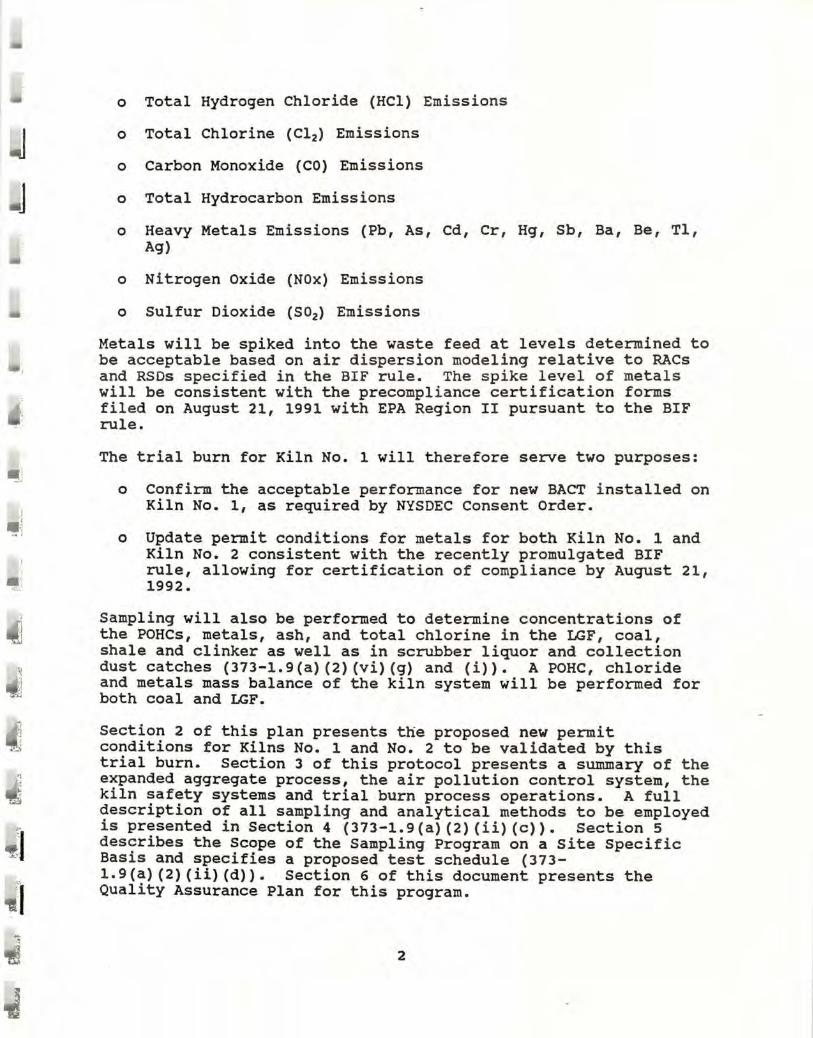
o Total Hydrogen Chloride (HCl) Emissions
o Total Chlorine (Cl2) Emissions
o Carbon Monoxide (CO) Emissions
o Total Hydrocarbon Emissions
o Heavy Metals Emissions (Pb, As, Cd, Cr, Hg, Sb, Ba, Be, Tl, Ag)
o Nitrogen Oxide (NOx) Emissions
o Sulfur Dioxide (S02) Emissions
Metals will be spiked into the waste feed at levels determined to be acceptable based on air dispersion modeling relative to RACs and RSDs specified in the BIF rule. The spike level of metals will be consistent with the precompliance certification forms filed on August 21, 1991 with EPA Region II pursuant to the BIF rule.
The trial burn for Kiln No. 1 will therefore serve two purposes:
o Confirm the acceptable performance for new BACT installed on Kiln No. 1, as required by NYSDEC Consent Order.
o Update permit conditions for metals for both Kiln No. 1 and Kiln No. 2 consistent with the recently promulgated BIF rule, allowing for certification of compliance by August 21, 1992.
Sampling will also be performed to determine concentrations of the POHCs, metals, ash, and total chlorine in the LGF, coal, shale and clinker as well as in scrubber liquor and collection dust catches (373-l.9(a) (2) (vi)(g) and (i)). A POHC, chloride and metals mass balance of the kiln system will be performed for both coal and LGF.
Section 2 of this plan presents the proposed new permit conditions for Kilns No. 1 and No. 2 to be validated by this trial burn. Section 3 of this protocol presents a summary of the expanded aggregate process, the air pollution control system, the kiln safety systems and trial burn process operations. A full description of all sampling and analytical methods to be employed is presented in Section 4 (373-l.9(a) (2) (ii) (c)). Section 5 describes the Scope of the Sampling Program on a Site Specific Basis and specifies a proposed test schedule (373-l.9(a) (2)(ii)(d)). Section 6 of this document presents the Quality Assurance Plan for this program.
2

I
•
Final changes and/or modifications to this Trial Burn Plan will be presented in an addendum and will be submitted to the appropriate regulatory agencies for approval prior to the test burn. In addition, process upsets or required deviations from this pr~tocol will be dealt with as they arise. DEC will be · consulted for approval as applicable .
Following the completion of the trial burn test program, a complete report will be prepared for submission to NYSDEC. The report will contain a full discussion of results, all field and analytical data, process operating conditions, sampling and analytical methods, calibrations, and calculations (373-l.9(a) (2) (vi) (g) and (i)). The data from this trial burn will also be used to complete the Federal Certificate of Compliance for Kilns No. 1 and No. 2 due August 21, 1992.
3

I
•
2.0 PROPOSED PERMIT CONDITIONS
The trial burn will be performed to validate the following permit conditions for Kiln No. 1 and No. 2 •
Parameter
Minimum Heat Content, BTU/lb
Total Halogens,% (Maximum) Antimony, PPM (Maximum) Arsenic, PPM (Maximum) Barium, PPM (Maximum) Cadmium, PPM (Maximum) Chromium, PPM (Maximum) Lead, PPM (Maximum) Mercury, PPM (Maximum) Silver, PPM (Maximum) Thallium, PPM (Maximum) Beryllium, PPM (Maximum) copper Nickel Selenium Zinc Viscosity, ssu
Table 2-1
Proposed Permit Conditions LGF Characteristics as Fed
8000
3 200
50 600
30 1400 1090
45 500 300 1.2
1000 700
25 1000 3000
The above approximate values are based on typical analysis of these streams. Two months prior to the test a detailed waste characterization analysis will be provided, plus more detailed analyses will be performed based on samples taken and composited during the trial burn. Waste will also be characterized when materials are blended and staged for the trial burn.
4

ii:
J
J
Table 2-2
Mass Feed Rate Antimony Arsenic Barium Beryllium Cadmium Chromium Lead Mercury Silver Thallium Copper Nickel Selenium Zinc Total Halogens
Feed Rates, lbs/hr Proposed Permit Conditions
Shale
44000 .0088 6.86 51. 0
0.132 0.152
3.00 2.78
0.0352 0.132
0.0881 6.42 4.18
0.0528 13.7
0.836
LGF Feed
- 4800 0.96 0.24 2.88
0.0058 0.144
6.72 5.23
0.216 2.40 1.44 4.80 3.36 0.12 4.80
144
The total feed rate will remain within the present permit limit of 4800 lbs/hour per kiln. Tests will be performed under two conditions relative to waste feed.
Condition A
22 tons/hour shale feed coal fuel only
Condition B
22 tons/hour shale feed Feed rate LGF waste fuel - 4800 lbs/hr
or 80 lbs/min
The metals will be spiked to levels specified in the table above. These levels have been determined based on modeling procedures and standards specified under the BIF rule and New York State Air Guide -1. These levels are in compliance with ambient air quality standards (RSDs and RACs) required under New York State Air Guide -1 as well as those promulgated in the fina l BIF rule. These levels were filed on August 21, 1991 with EPA Region II in the form of a precompliance certificate requfred under the BIF rule. In addition, these maximum allowable levels were derived in a report entitled "Norlite Corporation-Allowable Metal Concentrations and Feed Rates in Shale and used at the LGF
5

, -
~
J J ~
1
~
Lightweight Aggregate Plant" prepared by ENSR Corporation and submitted to NYSDEC on September 23, 1991. This report demonstrated that the proposed limits are in compliance with both BIF and New York Air Guide -1.
In summary, the following changes are proposed over conditions previously tested on Kiln No. 2.
o Allowable LGF Viscosity of 3000 SSU
o Metals will be spiked into the LGF feed to demonstrate that the proposed metal feed rates, calculated in accordance with New York State Air Guide -1 and the BIF rule, are achievable.
In essence, this trial burn plan will verify the precompliance certification forms filed with EPA Region II on August 21, 1991, and satisfy the final certificate of compliance required by August 21, 1992. In addition, this trial burn will confirm compliance with New York State Air Guide -1, and will satisfy the terms of the consent order referenced above.
Current permit conditions for total mass feed rate of waste fuels will be maintained.
6

I
I
3.0 PROCESS AND OPERATIONS
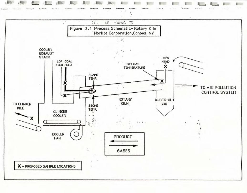
The Norlite facility produces an expanded shale aggregate in two dry process rotary kilns. Kiln No. 1, manufactured by Traylor is 175 feet long. Kiln No. 2, manufactured by Allis-Chalmers, is 180 feet long. Both kilns have an outside diameter of 11 feet and consist of a steel shell lined with 6-inch refractory brick, for an effective inside diameter of 10 feet. The burn zone extends approximately 30 feet from the burner end of the kiln. The burning zone gas temperature is maintained at 2200°F to 3000°F. A schematic of the process is shown in Figure 3-1.
3.1 Xiln Operations
Raw materials are quarried on-site and transported to the kiln via a conveyor system. The basic material {shale) is proportioned and stored in a silo or fed directly to the kiln. Table 3-1 presents a typical raw shale analysis. The raw product is introduced to the kiln at the feed {back) end from the silo, while fuels are fed from the opposite end. Calcination of the product occurs at a product temperature of 1700°F to 2000°F. The shale is then heated to the point of incipient fusion where it is in a semi-plastic state to expand internal gases, thereby creating voids. The cooled vitreous clinker is then discharged and stockpiled. The rated capacity of the kiln is approximately 25 tph clinker, but 20 to 22 tph is a more realistic maximum. Typically, 2.5 MMBtu are required to produce one ton of clinker at maximum capacity.
Heat is supplied by firing pulverized coal, No. 4 fuel oil, natural gas or Low Grade Fuel {LGF). All fuel is injected countercurrent to the product flow through the kiln through burners at the discharge {front) end of the kiln. Coal is uniformly fed to a Raymond coal mill where it is pulverized to a 200 mesh {70%-80%) and then fired through a single gun burner system rated at 5000 lbs/hour (coal at 12500 BTU/lb HHV and 80% passing through 200 mesh at less than 2% moisture and 30%-35% volatiles) supplied with 3970 ACFM conveying air at 170°F and 12" w.c. A typical coal analysis is presented in Table 3-2. The average coal firing rate is 2-3 tons per hour. Both coal and LGF will be fired during this test program.
Each kiln has thermocouples mounted at the kiln gas exit and heat exchanger outlet for monitoring process temperatures. Optical pyrometers monitor both flame and stone temperatures. LGF feed is monitored continuously with a Micromotion doppler flow meter, while a Merrick scale is used to monitor coal feed rates. Oxygen and carbon monoxide at the outlet to the baghouse are monitored continuously and recorded on a strip chart. In order to achieve a quality lightweight .aggregate product, the kiln is normally operated at approximately 8% to 10% oxygen at the back end with carbon monoxide concentrations less than so ppm. Typical kiln
7
ti!ilflJi.t 1"::..,.,.,, 1\• '"· - t;!_;. ll=" .. l'":-----:.. .. ,. A•~ .:,:::_ .. '-~- ~ I____. --- .___ _ _.._..,. ~ -...:..-:-- .,........,_. ~ .___.. ... _ ...... •••• • • I ~---_..
I)
COOLEH EXHAUST STACK
: .,.. • : ti°!, ~-F:i\( :~'..~:~, ~-!':·
Figure 3. 1 Process Schematic- Rotary KIin · · Norllte Corporation.Cohoes, NY
j'
. · HAW _/..--____ LGF COAL . f l:l· l) r ~ ,-.__
FEED FEED EXIT GAS . 1 . Q----__-·
I ..---.. FLAl"E TEMPEllATUll~r-XJ ___ 1
-----===:-TEMP, _ . -- X X _j_J~---~-:---- . ◄-:1 =:::--- ► TO All~ POLLUTION _;... =---~~------~r CONTROL SYSTEM t . ROT ARY KNOCl<-OUT
lO CLINKER STOf\E KILN OOX PILE V CLINKER TEMP. ~ .· COOLER . I•
X ------ ,-
~<> -~ :~: 1~• ' : . . - I
COOLER FAN
I X. PROPOSED SAMPLE LOCATIONS I
.,. •·!. I• ; I
I .
PRODUCT ... •
GASES
I I,
• I I ..
,, I
I

•"f.':A•':f.i-:•
• ID
,- .r.L It:..- --~-" lb. ~-JI [~c,_ I ~-- ' ~•=-· ii~ . I
·-· .. .. ,---·
HEAT EXCHANGER
MULflCLONE (
-FROM-rm 1/r -:-KILN -~ =IT·J
'-- I X.----. I
LIME SILO
X
ASH SILO
- --"1~· . : ... ;:. ,
BAGHOUSE
• . ... ....
301-1.P. BLOWER
MULTIPLE
I ' ll - ~ . __. , ___. • ~---..II -·· --- .......___ __. ·•·--...
.All»(C(C AIR POLLUTION D Cll,\RACTERIZATION and CONTROL, LTD.
KILN EXHAUST STACK
I X
., ~ 4001-1.P. FAN
MINIATURE __ _.,'\'-rvv'I-" t'IIST ~ MASTER ~.-:..11
GAS FLOW I
VENTURI I
QUAD SCRUBBER MMV - -~--- ·
I I
I I 1••
,· f-
l
. :· ·;. . £. ~ I I I MAKE- UP BLOt~WN I p H I WA TEA
·t I ·, . I RECYCLE ._
FIGUl1E 3-2 Pl10CESS SCHEMA TIC ·'- I .'. I TANK I QUARRY AIR POLtUTION CONTROL SYSTEM f.•: ·:
NORLITE CORPORATION, COHOES. NY : j·• ._ _____ _. XI CAUSTIC I
X • PROPOSED SAMPLE LOCATIONS, :
·• ' .I:
~

-
~
~
~
,: I!
i l '
i
1·: !
' J
~
l I j ·-I .
r
' . -
_!I':
~: :..:
·-~~
r~ .. ~~
. r !
~ ··
~ i..,;
.. ...: ... -
--..... ~
.. ":ir. --=--z= <5
...... ..... -z
1n
,=
. -
► z
.. • C:
0 -.J ,, '-0 C. '-
~ o IIU C '- CJ :, -=--L.. '-
c.:J O ..IZ
M I .
M

j
.l ff
•
!I
II
"
J
I
1
exhaust gas and material retention times are 15 seconds and 45 minutes, respectively.
Draft for the kiln is supplied by a Barron 400 HP induced draft fan rated at 53000 ACFM at 450°F. Secondary combustion air is supplied by forced draft clinker cooler fans rated at a total of 25000 CFM. The secondary combustion air is preheated by the clinker cooler at the front end of the kiln.
Table 3-1
TYPICAL RAW SHALE ANALYSES
Parameter
Si02 Al203 Fe20 3 cao Mg0 Alkali
Combustibles S03
Moisture
HHV
Sulfur
Volatile Matter
Ash
Fixed Carbon
Residual Moisture
Fineness
Table 3-2
TYPICAL COAL ANALYSIS
4% - 5%
12500 BTU/lb
<2%
32%
11%
52%
1% - 2%
70% - 80%
11
Percent Raw Shale by Weight(Dryl
58% 16%
6% 8% 3% 4% 5%
<0.5%
As received
Wet basis
Dry basis
As received
As received
As received
As fired
Passing 200 mesh as fired
J J
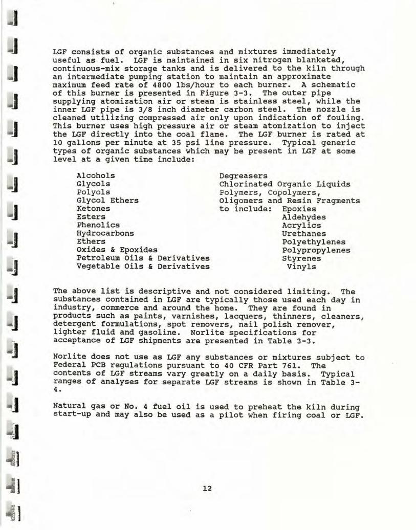
I.GF consists of organic substances and mixtures immediately useful as fuel. I.GF is maintained in six nitrogen blanketed, continuous-mix storage tanks and is delivered to the kiln through an intermediate pumping station to maintain an approximate maximum feed rate of 4800 lbs/hour to each burner. A schematic of this burner is presented in Figure 3-3. The outer pipe supplying atomization air or steam is stainless steel, while the inner LGF pipe is 3/8 inch diameter carbon steel. The nozzle is cleaned utilizing compressed air only upon indication of fouling. This burner uses high pressure air or steam atomization to inject the LGF directly into the coal flame. The LGF burner is rated at 10 gallons per minute at 35 psi line pressure. Typical generic types of organic substances which may be present in LGF at some level at a given time include:
Alcohols Glycols Polyols Glycol Ethers Ketones Esters Phenolics Hydrocarbons Ethers oxides & Epoxides Petroleum Oils & Derivatives Vegetable Oils & Derivatives
Degreasers Chlorinated Organic Liquids Polymer s, Copolymers, Oligomers and Resin Fragments to include: Epoxies
Aldehydes Acrylics Urethanes Polyethylenes Polypropylenes styrenes Vinyls
The above list is descriptive and not considered limiting. The substances contained in LGF are typically those used each day in industry, commerce and around the home. They are found in products such as paints, varnishes, lacquers, thinners, cleaners, detergent formulations, spot removers, nail polish remover, lighter fluid and gasoline. Norlite specifications for acceptance of LGF shipments are presented in Table 3-3.
Norlite does not use as LGF any substances or mixtures subject to Federal P_CB regulations pursuant to 40 CFR Part 761. The contents of LGF streams vary greatly on a daily basis . Typical ranges of analyses for separate LGF streams is shown i n Table 3-4.
Natural gas or No. 4 fuel oil is used to preheat the kiln during start-up and may also be used as a pilot when firing coal or LGF.
12

J
] Table 3-3
FEED SPECIFICATIONS LGF
] Maximum For
Component LGF Feed
] PCB 10 ppm
] Antimony 200 ppm
Arsenic 50 ppm
-' Barium 600 ppm
Beryllium 1.2 ppm
I Cadmium 30 ppm
I Chromium 1400 ppm
Copper 1000 ppm
~I Lead 1090 ppm
Nickel 700 ppm
~I Mercury 45 ppm
_I Selenium 25 ppm
Silver 500 ppm
.I Thallium 300 ppm
Organic Halogens 3.0%
·,.I · Sulfur 2.0%
Heating Value greater than 5000 ~I BTU/lb . .,__
~1 Viscosity Pumpable upon
delivery
... 1 ~1 13 >~
~1
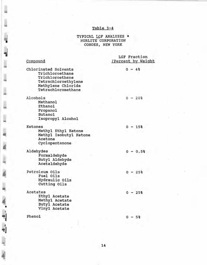
Table 3-4
TYPICAL LGF ANALYSES* NORLITE CORPORATION
COHOES, NEW YORK
Compound
Chlorinated Solvents Trichloroethane Trichloroethene Tetrachloroethylene Methylene Chloride Tetrachloromethane
Alcohols Methanol Ethanol Propanol Butanol Isopropyl Alcohol
Ketones Methyl Ethyl Ketone Methyl Isobutyl Ketone Acetone Cyclopentanone
Aldehydes Formaldehyde Butyl Aldehyde Acetaldehyde
Petroleum Oils Fuel Oils Hydraulic Oils cutting Oils
Acetates Ethyl Acetate Methyl Acetate Butyl Acetate Vinyl Acetate
Phenol
14
LGF Fraction (Percent by Weight
0 - 4%
0 - 20%
0 - 15%
0 - 0.5%
0 - 25%
0 - 25%
0 - 5%

• •· •
Compound
Aromatic compounds Benzene Toluene Xylenes Naphthalene
Aliphatic Compounds Hexane Heptane Pentane
Coal Tars
Fatty Acids
Waste Oils
PCBs
Organic Halogens
Table 3-4 (Cont.)
TYPICAL I.J:;F ANALYSES* · NORLITE CORPORATION
COHOES, NEW YORK
LGF Fraction (Percent by Weight)
0 - 25%
0 - 25% .
0 - 25%
0 - 5%
0 - 15%
< 10 ppm
< 3%
Heat Contents (as burned) > 8000 BTU/lb
* Actual analyses of LGF burned during the trial burn will be provided in the final trial burn report.
15

,
.....
~
• ' , ~
i • ~
3.2 Air Pollution Control System (373-l.9(a) (2) (ii) (f))
Both kilns will have identical emission control systems as shown in Figure 3-2. The systems include both wet and dry emission control devices for the collection and removal of particulate matter, hydrogen chloride (HCl), metals and other gaseous species. The principal collection mechanisms affected are sedimentation, condensation, impaction, filtration and interception for particulate and metals and absorption for HCl and other gaseous species.
Kiln emissions first pass through a mechanical collector (knockout box) to remove large particulate matter and a Barrons multiple cyclone unit (multiclone) incorporating relatively small diameter cyclones operating in parallel with a common inlet and outlet. The multiclone is provided to remove coarse particulate matter and is rated for 2•3 in. w.c. pressure drop. Dust collected in the multi-clone accumulates in a hopper which returns it to the clinker conveyor as useful product.
The gases then pass to the air. cooler, an air to air, one tube bundle heat exchanger rated at 65000 ACFM. This unit uses forced draft ambient air for the cooling medium. Gases enter the heat exchanger at approximately 900°F and exit at approximately 450° with a 2-3 inch w.c. pressure drop across the unit.
Following the heat exchanger is a new Aeropulse, Inc. Power Pulse Collector (fabric filter) with three modules and 17334 square feet of filter area. ~he unit is rated for 52700 ACFM at 450°F. The air cloth ratio is 3.04:1 with all three modules operating and 4.50:1 with one down for maintenance. Polyamide P-84 (14 oz.), with a permeability of 25 to 35 cfm per square foot at o.s in. w.c. is used as filter media for the 810 sets of filter assemblies. The filter media is continuously pulsed one row at a time, controlled by a 10 position timer. Tribo-Flow indicators are installed to detect the presence of broken bags. A modulating air damper automatically adjusts inlet gas temperatures (if required) to 400°F to 425°F (± 5°F) by bleeding in ambient air. Pressure drop across the unit is rated between 2-6 in. w.c., with all three modules on-line.
16

I
... ·•·"·-·
Hydrated lime (Ca(OH) 2), stored in a 2500 cubic foot silo, is injected into the air pollution control system immediat ely prior to the baghouse. This is primarily to control sulfur dioxide and sulfuric acid mist from the combustion of coal in the k iln and to protect the baghouse from resulting corrosion. The lime also neutralizes hydrogen chloride, providing approximately 80% of the removal prior to the wet scrubber. The baghouse is expected to control 60% of the S02 and S03 introduced from the kiln. Lime feed will vary from near zero to 330 pounds per hour, depending upon the fuel type and feed rate.
The baghouse is followed by a 400 HP system fan which induces draft through the kiln, knock-out box, multiclone, heat exchanger and baghouse and provides forced draft on the exhaust gases through the venturi and Oucon scrubbers and mist elimination units. Additionally, the fan provides induced draft for a hood installed over the kiln shale feed chute, designed and installed to capture any fugitive emissions emanating from this area.
The induced draft fan carries exhaust gases to a BECO Venturi (MMV) scrubber for acid gas removal. This unit is rated for 53000 ACFM at 450°F at the inlet and 38600 ACFM at 138°F at the outlet, with 2 to 6 in. w.c. pressure drop. The scrubber is a rod design that has tubular stainless steel rods installed in rows across the throat to provide a series of smaller throats. The intent is to provide the effect of a small venturi throat without incurring the high pressure drop typically associated with conventional high efficiency venturi scrubbers. Additionally, the tubes provide additional impaction surfaces for enhanced particulate and HCl collection. The scrubber is designed for 99% HCl and 68% S02 removal efficiencies.
Clean (city) water and air atomization headers are located directly above the venturi to provide sensible cooling to the exhaust system. Caustic sodium carbonate (soda ash) solution, comprised of a maximum of 10% dissolved solids (sodium carbonate, sodium chloride and/or sodium sulfate), is recycled through the unit at approximately 200 gpm. It is introduced through tangentially positioned nozzles located directly above the MMV module. Scrubbing solution is also injected into the transition segment located between the venturi MMV and oucon units.
Excess water drains from the venturi exit elbow to the 1000 gallon settling/recycle tank. The pH of the solution in the recycle tank is automatically maintained at pH 8 or greater by the introduction of 5% sodium carbonate solution to the venturi feed at rate of 7 gpm. Blowdown is taken from the recycle pump discharge to maintain a constant solids concentration in the solution. Blowdown is expected in the range of 1.75 to 5.0 gpm, depending on the quantity of fuel burned as well as the chloride and sulfur contents.
17

1
I
;j
~i ~ ..,,
Following the BECO unit is a BECO MMV mist eliminator installed in the bottom of the Ducon polishing scrubber. The unit, manufactured of PVC, is designed to capture entrained droplets of caustic solution exiting the BECO scrubber. This unit is rated for a pressure drop of 1.5 to 4 in. w.c. This mist eliminator drains into the recycle tank.
A further modification of the Ducon unit consists of the insertion of a Mist Master stainless steel mesh-type mist eliminator at the top of the unit immediately preceding the exhaust stack. This unit has a rated capacity of 48000 ACFM at 140°F with a minimal pressure drop. The Ducon unit functions as an entrainment separator for the venturi scrubber. Kiln exhaust passes to the atmosphere via a 60 inch diameter stack 120 feet above grade at approximately 42000 ACFM at 140°F and 10% moisture (v/v).
3.3 Kiln Safety Systems (373-1.9 (a) (2) (ii) (b))
The kiln is manned on an around-the-clock basis by the burner operator. Assisting the burner operator is one trunion operator per shift who is responsible for activities outside of the control room and burner floor area.
In the event of a power failure, all systems shutdown. This includes: solenoid valves on the LGF discharge from the storage tanks, solenoid valve at pump house #2 (LGF feed to kilns), coal mill, fans, kiln drive, raw shale input, etc.
In order to restart, the following must take place:
1. Pilot with natural gas 2. Prove flame temperature 3. Manual restart/reset of system at fuel pumping area at tank
farm and at pump house #2
In the event of a flame-out while burning LGF:
The Honeywell pyrometer will sense a temperature drop of the flame temperature. If the temperature is not restored within 2.5 minutes to 2200°F, audible and visual alarms are sounded. If after an additional 2.5 minutes (total 5 minutes) corrections to the problem have not been made or were not successful, the LGF solenoid will automatically shutdown.
The kiln is manned around-the-clock by the burner operator who is constantly monitoring operations. Any flame-out is immediately detectable by loss of temperature on the flame temperature recorder. The temperature within the kiln and the kiln
18

' ~ C .
4 ~ ~
refractory will provide sufficient heat to maintain a burn . zone temperature . in excess of 2000°F for at least 5 minutes in the event of loss of flame. In order to restart after this occurrence, the same procedure previously described for a power failure must be utilized.
A Honeywell optical pyrometer is installed for flame detection. In addition, kiln exit gas temperature is monitored by a thermocouple. If back end temperatures drop below 880°F, immediate operator response is initiated to avert shutdown. A 880°F back end temperature enables the kiln to maintain the 2150°F expansion temperature required to produce a quality lightweight aggregate product.
Burner operators are continually monitoring and logging key operating parameters and are conscious of changing readings or unusual noises which can be indications of potential problems. In addition to the above safety features, a valve is installed to manually stop the flow of LGF to the burner if one or more of the following events occur.
1.
2.
3.
4 •
5.
6.
7.
a.
Kiln gas monitoring system indicates incomplete combustion (02 <3% or co >100 ppm for 10 minutes).
The LGF feed monitoring system fails
Exit gas temperature falls below 880°F
Kiln feed is interrupted for more than 60 minutes
Kiln rotation ceases
Air pollution control system failure (i.e., high/low pressure drop)
Maximum LGF feed rate is exceeded
Kiln pressure exceeds -0.05 in. w.c.
For any other non-routine failures, the standard operating proc~dure is to shutdown the LGF feed, switch to natural gas or coal, define the problem and initiate corrective action. Items such as scrubber or baghouse malfunction, loss of atomizing air/steam, ID fan loss, etc. would be covered by this SOP. The loss of the ID fan would warrant the shutdown of the entire process to avoid a meltdown. As long as this 400 hp fan runs, however, the kiln is maintained under negative static pressure eliminating the possibility of fugitive emissions.
19

■' ,'
'1 .J •
3.4 Trial Burn Process Operations (373-l.9(a) (2) (ii) (e))
The Trial Burn will be performed under two distinct kiln operating conditions. Three initial tests will be performed for POHC, particulate, metals, HCl, chlorine, NOx, sox, CO, and opacity while the kiln is firing coal at or near the maximum rate and producing approximately 18 to 22 tph clinker. Then, three trial burn tests will then be performed for the same parameters while the kiln is firing approximately 100% (nominally 80 lbs/min) LGF and producing 18 to 22 clinker. All LGF will contain a minimum of 8000 BTU/lb and a maximum of 3% halogen as per current permit conditions. An effort will be made to procure and blend a waste fuel simulating as closely as possible worst case conditions. These tests should prove the acceptability of LGF as an alternate fuel at rates ranging from Oto 80 lbs/min.
If desired by NYSDEC, three particulate test runs will be performed while the baghouse is operating on two modules. additional three runs will be performed while the kiln is on LGF.
These fired
Kiln and air pollution control system data will be recorded during the tests described above either continuously, at 30 minute intervals or both. The following parameters will be continuously monitored and recorded on a strip chart: 02 , CO, Back End Gas Temperature, ID Fan Amps, and LGF Feed. The following parameters will be monitored at 30 minute intervals: Kiln Speed, ID Fan Damper Setting, Coal Feed, Lime Feed, Settling/Recycle Tank pH, Scrubber Recirculation Flowrate, Blowdown Rate and Pressure Drops across the multiclone, heat exchanger, baghouse, venturi and Ducon. In addition, blowdown samples will be drawn at 60-minute intervals for total solids analyses. Table 3-5 presents a summary of the parameters to be monitored during the Trial Burn program. All strip charts and recorded process data for the Trial Burn shall be included in the Trial Burn Report.
The LGF will consist of organic substances and mixtures which will be immediately useful as fuel or which will be blended into a useful fuel. One 24000 gallon storage tank, and possibly one backup, tank will be filled with LGF and then spiked with surrogate POHCs and metals described later in this section in a quantity to ensure the calculation of DREs and metals feed limits taking the detection limit of the emission measurement and analytical methods into consideration. This analysis will include the use of stack gas volumetric flow rates, estimated sample volumes and VOST detection limits to determine the amount of surrogate POHC required to exceed the required DRE by a factor of 10. Spiking compounds will be purchased in their "pure" state in drums and blended into the 24000 gallon storage tank.
20

In no case will the chloride content of the LGF exceed 3%, including surrogates. BTU values will be adjusted by blending different fuel loads to achieve the minimum heat value achievable. Under no circumstances will water be added to the LGF to lower the BTU value. It should be noted that LGF is not on the open market and cannot be ordered from suppliers to meet exact specifications. A maximum effort will be mad~ to produce and blend a "worse case" LGF.
A LGF sample will be drawn from the recycle pump after the mixed tank has been circulated at 150 gpm for a period of at least four hours and is well mixed. The samples will be analyzed for Norlite Specification Limits prior to use. The tank inlet and outlet valves will then be sealed until the Trial Burn.
The characteristics of potential POHCs in LGF are presented in Table 3-6. Given these analyses, tetrachloromethane (carbon tetrachloride), tetrachloroethylene (perchloroethylene) and 1,1,1-trichloroethane (methyl chloroform) have been selected as the surrogate POHCs for this Trial Burn. These same surrogates were approved by NYSDEC and used in the Trial Burns performed in January/February 1989 and June 1990 with considerable success. Tetrachloromethane has the lowest heat of combustion of the compounds listed and is therefore the most difficult to destroy by thermal means. Acceptable DRE for this compound will demonstrate the acceptability of the kiln for the destruction of all organic compounds with higher heats of combustion. The other two compounds will provide a broader basis over which to evaluate the kiln DRE.
Although toluene represents the probable maximum fraction of most LGF mixtures, it will not be used as a surrogate POHC for this program. It should be noted that toluene is a potential product of the combustion of coal and fuel oil, and has been detected in emission concentrations of similar magnitudes when firing waste fuel streams with high toluene contents. The three compounds listed will be added to the LGF in sufficient quantities prior to the trial burn to ensure the calculation of acceptable DREs. It should be noted that the chosen surrogates have boiling points within the range specified by the VOST Method. EPA audit samples will be run with trial burn samples to afford a measure of absorption and desorption efficiencies.
21
~ ~, • ,1 q
~
~
. ··- ........ ...... _ .. ·- ........ ... , •··· . . . . . . ·-· ... .. ..... .
3.5 Post Trial Burn Operations (373-l.9(a) (3) and-2.15(d) and(f)
For the period of time following the completion of the trial burn and prior to final permit condition modifications, the following operating parameters will be monitored by Norlite to ensure compliance with emission limitations and a 99.99% DRE.
o LGF constituents as per Waste Analysis Plan o LGF feed rates o Kiln exhaust co and 02 concentrations o Kiln back end temperature o Combustion gas velocity indicator (Fan amps) o Shale Feed Rate o Air Pollution Control System pressure drops
{Baghouse, Venturi, Ducon)
22

1
Table 3-5
KILN AND AIR POLLUTION CONTROL SYSTEM OPERATIONAL DATA
LGF TRIAL BURN
Parameter
oxygen(%)
carbon Monoxide (ppm)
LGF Feed Rate (lbs/hr)
LGF Feed Line Pressure
LGF Atomization Pressure
Coal Feed (lbs/hr)
ID Fan (amps)
Back End Temperature (°F)
Baghouse inlet Temperature (°F)
Kiln Pressure (in.w.c.)
ID Fan Damper(%)
Shale Feed (tph)
Clinker Production (tph)
Lime Feed (l~s/hr)
Recirculation Tank (pH)
Scrubber Water Recirculation Rate (gpm)
Scrubber Water Blowdown Rate (gpm)
PRESSURE DROPS
Multiclone (in.w.c.) Heat Exchanger (in.w.c.) Baghouse (in.w.c.) Venturi Scrubber (in.w.c.) Ducon Scrubber (in.w.c.)
,.,
Monitoring Frequency
Continuous
Continuous
Continuous
JO-Minute
JO-Minute
JO-Minute
Continuous
Continuous
Continuous
Continuous
JO-Minute
JO-Minute
JO-Minute
JO-Minute
JO-Minute
Continuous
Continuous
JO-Minute JO-Minute Continuous JO-Minute JO-Minute

-ttL~ 4-.. ,"'• - ~L [-. •I
··it:.~. ·.•t •. :_:;t, !
>·•
: ;2~F HA~AR~~~EC~~TITUENTS] NORL ITE CORPORATION
' ·. COHOES; NEW YORK
· Heat -oo ii1i)Ol=ract·foo--·····----·--·· ... -...... -· CornpOU1d formula Molocular cf P,)lnt d 5ynonyr,,
. Weight Combustion 1.GF (KCAL/gram) < :{;.L_j% :!Jl _____________________ ... ·-
Ml ctrachlororocthane CCl4 15J.0 0.24 76.U" <J% . Carbon lctrac:hlorwc: I•
' ·•fJ ctrachlorocthylcne c2c1,1 165.0 1.19 121.2· <:11' J.>orchlorocti-.y lor.t}
N
I ·1r1cllloroctheno C2HCIJ I J 1.4 1.74 0·1.2 · ,:s 1~ 'I l'ICl)I0fOC:hlyhmc ""
" 1, 1, 1-rr 1c_1, 1orocthc1nc OIJCCIJ I JJ.4 1.99 7 .. 1,0· <:S?~ t·lclhyl Chloror (1ml
Formaldehyde HCHO JO 4.47 -19 <0. 5¾ f1cthanal
Pllenol C6H5Ot-l 94.1 I · 7.70 101.0- <51~ Cclrbol lc Acl<I
CH3COCH2CHJ , it :~2.11 .1,
t1cthyl ~thyl Ketone- 6.07 I' I •19,6• < I Sr. I
2-Buthnor~ I
J
Maph tllalcnc CIOt-18 1·20.17 9,62 21 o.o· <2Sr. Tar Cainr,hor I
Ocnzcne C6t-16 78.1 I I 0.0:S . 00.1 • <25?~ HKHMH
Toluene C6H5CHJ 92.14 . I 0.14 I I0.6° <25~ Methyl Ocnzanc • ,1_, __
·-• ··---.. --·---·-·-·-· " Surrogate POHC
_.,.. - --------.. ·--·~· - --·-- -- ·- - -~ - ·- . .

,
'
4,0 SAMPLING AND ANALYTICAL METHODS
Air pollution emission measurements will be performed during the trial burn at the exhaust stack of the scrubber to determine emission concentrations and rates of POHCs, particulate matter (PM), heavy metals (HM), hydrochloric acid (HCl), chlorine (Cl2 )
nitrogen oxides (NOx), sulfur dioxide (S02 ), carbon monoxide (CO), oxygen (02 ) and opacity. Sampling will also be performed at the kiln outlet to determine concentrations of 02 and CO2 as well as volumetric flow rate in order to calculate kiln gas residence times (373-l.9(a)(2)(ii)(c)).
In addition to the air pollution measurements, samples will be drawn from the multiclone, baghouse, scrubber blowdown and the clinker cooler discharge conveyer. Raw shale feed samples will be taken at the entrance to the kiln at the back end. Coal samples will be takeri at the coal feed belt. LGF samples will be drawn from the feed pipe on the burner floor. All of the above sample fractions will be analyzed for POHC, metals and chloride content in order to calculate DRE, perform a mass balance of the kiln system for chlorides and metals, and to evaluate any possible contamination.
4.1 Stack Emission Measurements
Emission Measurements will be performed to determine emission concentrations and rates of POHCs, PM, heavy metals, HCl, Cl2 ,
N0x, S02 , CO, 02 , CO2 and opacity. Sampling will be performed in accordance with EPA Reference Methods 1, 2, 3, 3A, 4, 5 (modified), 6C, 7E, 10, and the EPA VOST (SW846 Method 0030) procedure. Metals will be determined using the Multipl e Metals Sampling Train as described in the EPA Methods Manual for Compliance with the BIF Regulations (EPA/530-SW-91-010 , December 1990). Hexavalent chromium will also be determined in accordance with procedures defined in this manual. Hydrogen chlor ide and chlorine will be determined in accordance with EPA Method 0051 as described in the above manual.
4.1.1 POHC Emission Measurements
Sampling will be performed to determine the emission rate and DRE of the surrogate POHCs by utilizing the EPA Volatile Organic Sampling Train (VOST) procedure as outlined in EPA-SW846 Method 0030. The slow VOST option will be used. This option requires three 40-minute samples to constitute a test series.

"
II.~ a._, • ____ .... . ... .
:;::··. !•iit-:-,t:: •: . . : . .... "\ . . ••. , , ... 'r~::
?(¥!1': ... , . ·t·' •t,.f.•. •II., •• • .
figure 4-1 Volallle 0r9~~1c s~,'.npu~g_:~raln (VOST) ] APCC A Ill POU ll l'I 01·1 CMAllAC: I ~Hll Al IOII and CON'I HOI.. I 11)
GLASS WOOL PARTICULATE FILTER I
\ )BE PR(
f/SfN.~. --► --..... ) -·- --,--d . . . .. - •,
r::;:· -~ -~ . l . ICE ,,,
---
STACK
::, WATER
~- ◄-·-g-_ . TENEX TRAP
h CONDENSATE TRAP IMP INGER
' .
EMPTY
TENEX TRAP
•I ' • I
CHARCOAL BACKUP
SILICA GEL
______ _,,;
·--------
VACUU1·•1 INDICA ror~
c;) ..... -
,,,.,.,..-· ··-··· .... ► ..... ----·· ..... .
TO PUt"IP
ROTOt-lETEri
I•
I .

J .l
.....i
Sample Collection
A 20-liter (nominal) sample of effluent gas containing POHCs is drawn from the source at a flow rate of approximately 0.5 liters per minute for 40 minutes, using a heated (250±25°F) glass lined probe and a VOST sampling train. A schematic of the train is shown in Figure 4-1. The gas stream is cooled to <20°C by passage through a water cooled condenser and volatile POHCs are collected on a pair of sorbent resin traps. Liquid condensate is collected in an impinger placed between the two resin traps. The first resin trap (front trap) contains approximately 1.6 grams Tenax and the second trap (back trap) contains approximately one gram each of Tenax and petroleum based charcoal, 3:1 by volume. A total of four pairs of sorbent traps will be used to collect volatile POHCs from the effluent gas stream for each test. Three pairs for each test run plus one spare pair (in the event of analytical problems) will be utilized. A total of three tests (12 cartridge pairs) will be performed under each test condition (coal/liquid LGF/liquid and solid LGF) for a total of six tests (24 cartridge pairs). A velocity traverse will be performed in accordance with EPA Methods 1 and 2 at the beginning and end of each test in order to determine exhaust volumetric flow rate and mass emission rates.
Sample Recovery
All sample carriages will be sealed with Swage-lok fittings and kept on ice until ready for analysis. Condensate will be recovered and combined for each test series. Past experience during the previous trial burn has shown only a few ml to be collected in four test runs combined since most of the moisture was adsorbed by the Tenax.
Sample Analysis
Sample analysis will be performed in accordance with SW846 Method 0030. The contents of the paired sorbent cartridges are spiked with an internal standard and thermally desorbed for 10 minutes at l80°C with the carrier gas flow reversed so that the effluent flow from the analytical trap is directed into the GC/MS. The volatile POHCs are separated by temperature programmed gas chromatography and detected by low resolution mass spectrometry. The concentrations of volatile POHCs are calculated using the internal standard technique. Condensate samples are analyzed in a similar manner. Results are typically in the nanogram range. If POHC concentrations are detected in the first sample in the range of suspected breakthrough, the remaining cartridges will be analyzed separately rather than in pairs.
27

J
J
1 .. , •·
~ j ~
◄
. ·•·- . -· .. ·-- - . '
4.1.2 Particulate and Heavy Metals Emission Measurements
Sampling will be performed to determine emission of particulate and heavy metals using the multiple metals sampling train . described in Section 3.0 of the EPA Methods Manual for Compliance with the BIF Regulations. Samples will be analyzed for antimony, arsenic, barium, beryllium, cadmium, chromium, lead, mercury, silver and thallium. In addition, particulate (PM) will be sampled using this train.
Sample Collection
Sampling will be performed isokinetically at traverse points as presented in Section 5. Twenty-four points will be sampled for 3 minutes each for a total test duration of 72 minutes and a minimum sample volume of 30 DSCF. A typical sample volume is expected to be in the range of 50 to 60 DSCF.
Particulate and metals sampling will be performed using the multiple metals sampling train depicted in Figure 4-2. The train consists of a quartz nozzle, quartz probe, filter, a flexible Teflon umbilical line, seven impingers, vacuum pump, dry gas meter and an orifice flow meter. Complete sampling train calibrations are performed before and after every compliance test program.
A quartz nozzle is attached to a glass-lined probe which is heated to 248±25°F to prevent condensation. Fiberglass filter paper supported in a 4-1/2 inch glass filter holder is used as the collection media. The filter assembly is enclosed in a heated box to maintain temperatures at 248+25°F. A thermocoupl e is located inside the back half of the filter holder, to monitor the gas stream temperature and verify that it is kept below 275°F. An ice bath containing seven impingers is attached to the back end of the filter via a flexible, heated Teflon tube. The first impinger is empty as a moisture knockout, the second and third impingers each contain 100 ml of 5% nitric acid/10% hydrogen peroxide solution, the fourth is empty. The fifth and sixth contain 100 ml 4% potassium permanganate/10% sulfuric acid. The seventh contains 200 g of indicating silica gel· to remove any remaining moisture. Flexible tubing, vacuum gauge, needle valve, leakless vacuum pump, bypass valve, dry gas meter, calibrated orifice and inclined manometer complete the sampling train. The stack velocity pressure is measured using a S-type pitot tube and inclined manometer. The stack temperature is monitored by a thermocouple that is attached to the pitot and connected to a potentiometer. A check valve is not used in this sampling train.
A nomograph is used to quickly determine the orifice pressure drop required for any pitot velocity pressure and stack temperature in order to maintain isokinetic sampling conditions. Sampling flow is adjusted by means of the bypass valve. Before
28

------ -
..
11· .51.
I
n i ~~ .
> N ...
.,;.
11
-0
' -=
fJ -
- ~
•
~ g
{,! l a
. !i
C
u 0
)II
u
-,. C:
it •
-;
. =
~~
r
-
E i .!!l ~
Q
~ .. • I I
j
,., JI ~ ::
1 I ' e
... . J ...
Sl
ft
_g.
i
;
I e
-,. 0
,0
II
u ;
l r, E Q
~
' I!! lj t
! N I ~
C, - "" :::s Cl(
~ .... t:.
. ~ I ilM CE$
,/ L ,
~ • 15.
I . ! ii!
i
~a:
.. ., ~ ..
29 . ..

7 J
~
~
~
1 4 I
and after each test run the sampling train is leak checked (acceptable at less than 0.02 cfm).
Test data is recorded on field data sheets as presented in the Appendix.
Sample Recovery
Sample recovery will be performed in a relatively clean and windfree shelter constructed on the stack. After the probe has been removed from the stack and allowed to cool, particulate matter is wiped from· the exterior of the nozzle and the nozzle capped to prevent loss (or gain) of sample. The Teflon sample line is then removed from the filter holder and impinger train. The filter outlet is sealed with Para-film. The Teflon sample line is sealed at both ends. The impinger outlet vacuum line is then removed and the impinger train sealed. The impinger train is inspected and abnormal conditions noted before disassembly. Samples are recovered and placed in Teflon sealed glass containers as follows:
Container No. 1
Container No. 2
Container No. 3
Container No. 4 (Impingers 1,2,3)
- The 4-1/2 inch glass fiber filter is removed from its holder and placed in a petri dish, sealed, and labeled.
The probe, nozzle and front half of the filter holder are brushed and rinsed three times with acetone. The wash is deposited in a 500 ml sample jar and labeled.
- The probe, nozzle, and front half of the filter holder are brushed and rinsed three times with nitric acid solution. The wash is deposited in a 500 ml sample jar and labeled.
- The volume of the HN03/H202 impingers and moisture knockout impinger and rinses are measured to within o.s ml and recorded. The solutions are then deposited in a 1000 ml glass sample jar. The impinger, Teflon line, and the back half of the filter holder are then rinsed three times with 100 mls of 0.lN nitric acid solution and the rinse added to the impinger solutions. The jar is sealed and labeled, and the liquid level marked.
Container No. SA - The volume of liquid in impinger #4 · is measured to within o.s ml. The impinger is then rinsed with 100 ml of 0.lN HN03 and the rinses are placed into container No. SA. The jar is sealed and labeled and the liquid level is marked.
30

• •
-· •
-
Container No. SB - The volume of liquid from impingers 5 and 6 is measured to within o.s ml, and the liquid transferred to container No. SB. Using 100 ml total of fresh acidified potassium permanganate solution, impingers 5 and 6 and connecting glass pieces are rinsed three times and the rinses are placed into container SB, being careful to transfer loose precipitated materials from the impingers. Using 100 ml total of water, impingers 5 and 6 and connecting glass pieces are rinsed three times, and the rinses are placed in container SB, again carefully transferring precipitated material. The jar is sealed and labeled and the liquid is marked.
Container No. SC - Place 200 ml of water in sample container SC. Then the impinger walls of impingers 5 and 6 are washed with a single aliquot of 25 ml of 8NHC1. The jar is sealed and labeled and the liquid level is marked.
Container No. 6 - The silica gel is replaced in its original container.
All samples are placed in shock-proof containers for transport to the analytical laboratory.
Sample Analysis
Particulate analysis will be performed in accordance with EPA Methods, and heavy metals (Pb, As, Sb, Cd, Cr, Tl, Be, Ba, Hg, Ag) analyses are performed using ICAP and/or AAS technique defined in EPA's Method Manual for Compliance with BIF regulations, Section 3.0.
Container No. 1 - The glass fiber filter is desiccated for at least 24 hours and weighed to a constant weight. The filter is then divided and digested with concentrated nitric and hydrofluoric acids in a microwave oven.
Container No. 2 - The acetone wash is evaporated at room temperature and weighed to a constant weight. The wash is then digested, combined with the contents of Container No. 1.
Container No. 3 - The nitric acid wash is acidified, reduced to dryness and digested as Container No. 1. The sample is then combined with Container Nos. 1 and 2 for heavy metals analyses. The combined digested solutions are labeled
31
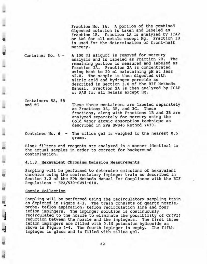
• Fraction No. lA. A portion of the combined digested solution is taken and labeled as Fraction 1B. Fraction lA is analyzed by ICAP or AAS for all metals except Hg. Fraction 1B is used for the determination of front-half mercury.
Container No. 4 - A 100 ml aliquot is removed for mercury analysis and is labeled as Fraction 2B. The remaining portion is measured and labeled as Fraction 2A. Fraction 2A is concentrated using heat to 20 ml maintaining pH at less <2.0. The sample is then digested with nitric acid and hydrogen peroxide as described in Section 3.0 of the BIF Methods Manual. Fraction 2A is then analyzed by ICAP or A~S for all metals except Hg.
Containers SA, 5B and SC These three containers are labeled separately
as Fractions 3A, 3B, and 3C. These fractions, along with Fractions 1B and 2B are analyzed separately for mercury using the Cold Vapor atomic absorption technique as described in EPA SW846 Method 7470.
Container No. 6 - The silica gel is weighed to the nearest 0.5 grams.
Blank filters and reagents are analyzed in a manner identical to the actual samples in order to correct for background contamination.
4,1.3 Hexayalent Chromium Emission Measurements
Sampling will be performed to determine emissions of hexavalent chromium using the recirculatory impinger train as described in Section 3.2 of the EPA Methods Manual for Compliance with the BIF Regulations - EPA/530-SW91-010 • .
Sample Collection
Sampling will be performed using the recirculatory sampling train as depicted in Figure 4-3. The train consists of quartz nozzle, probe, teflon aspiration, teflon recirculation line and four teflon impingers. The impinger solution is continuously recirculated to the nozzle to eliminate the possibility of Cr(VI) reduction between the nozzle and the impingers. The first three teflon impingers are filled with O.lN potassium hydroxide as shown in Figure 4-4. The fourth impinger is empty. The fifth impinger is glass and is filled with silica gel.
32

w w
L L L ,1 ··· ._,~,., ~,., .._,o., ' ·" It , ,
t,
TEFLON\ LINES .--. . _,. .... I
I ? F} _\ . i.l'~~.!
}fr?·t 150ml
0.1 NKOH
TEFLON IMPINGEAS
75ml 0.1 N KOU
WAlEA ANO ICE DAIii
I I
Figure 4- 3
GLASS MPINGER
SL~' GEL .
.___. • ......_j
► TO
Mf Tt IOO 5· T't'PE METEADOX
SchemallC ol rocitculalory lmpinoor lrain wilh asp11a1or assombty. (or hoxavalcnt d1ruulum 4ll~ /1'.JO

-•
1 -Ji
Sample Recovery
A post test nitrogen purge is performed to prevent the conversion of hexavalent chromium to the trivalent state. ·
Container No. 1 - The volume of impingers No. 1 through 4 are measured to within 0.5 ml and recorded. The contents are transferred to polyethylene sample container. Then 100 ml of water is used to rinse four times the glass nozzle, aspirator, recirculatory lines, irnpingers and connecting tubing. The rinses are combined with the impinger solutions in the container. ·The jar is sealed and labeled and the liquid level marked.
Container No. 2 - The silica gel is replaced in its original container. :
Sample Analysis
The sample from container No. 1 is filtered through a 0.45 micron filter, rinsing the sample container three times with DI water and passing this also through the filter as described in Section 3.2 of EPA SW-91. The final volume of the filtrate is determined. The sample is then immediately analyzed by ion chromatography coupled with a post column reactor and a visible wavelength detector.
4,1,4 Hydrogen Chloride and Chorine Emissions Measurements
Emissions of hydrogen chloride (HCl) and chlorine (Cl2 ) will be determined in accordance with EPA Method 0051 Section 3.3.2 of the EPA Methods Manual for Compliance with the BIF Regulations (EPA/530~SW-91-010, December 1990). Sampling and analysis will be performed in accordance with the method using a sampling train schematically identical to the one presented in Figure 4-4.
The sampling train consists of a teflon filter and six midget impingers in series. The first impinger is empty, while the second and third each contain 15 ml of 0.lN sulfuric acid solution, and the fourth and fifth impinger each contain 15 ml of a 0.lN sodium hydroxide solution. The sixth impinger contains silica get to remove any remaining moisture from the sampling train.
Sampling is performed non-isokinetically at a single point in the stack at 2 1pm (nominal) over a 60 minute period. Upon the conclusion of each test, the sampling train is leak checked. The contents of the first three impingers and water rinses is deposited ih a glass sample jar with a Teflon lined lid. The contents of the fourth and fifth impingers are transferred to a
34

L
w V1
~. L- ,1 ____ , •. ,
. ,-, .. alfll n,,..,
~t!ONIIII ti .. ·• . J1 : Ir! :g3
il I . .. t .... .
" I RUf fMA
IUM
.....
\, .,.,
,,.. ....... ----··P'IIONllll
l., ~----~
6)..;.,...,1.3.~ . (D V..,. I 3.J.JBI
e ........ '3.3-JAI
L •. , __ ,
n • ....,...,,.
•·-
nt1W1_, OIAU
IIOf'COCII
~igure 4-4 -Mi~get Impinger HCl/Cl2 Sampling Train
I__, I___,
•
.. . • . .

, -, -
.J
separate sample jar along with rinses. in triplicate with distilled-deionized bottle. The bottle is sealed, labeled sample.
All impingers are rinsed water into the same and shaken to mix the
Sample analysis is performed using EPA Method 9057 by Ion Chromatography.
4,1.5 02 CO2 and CO Manual Determination
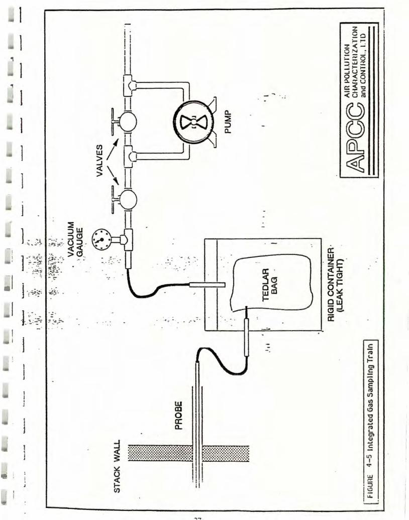
An integrated gas sample is drawn from the exhaust stack into a Tedlar bag at approximately 0.25 1pm simultaneously with each particulate test performed as described in Section 3.1.2. These samples are drawn through a probe integral with the main sampling probe and analyzed on a dry basis in accordance with EPA Method 3A with Westinghouse/Maihak combustion gas analyzers as described below in Section 3.1.4. Percent CO2 and 02 , as well as ppm CO and the molecular weight of the gas stream, are determined from the analyses. A schematic of the sampling train is presented in Figure 4-5.
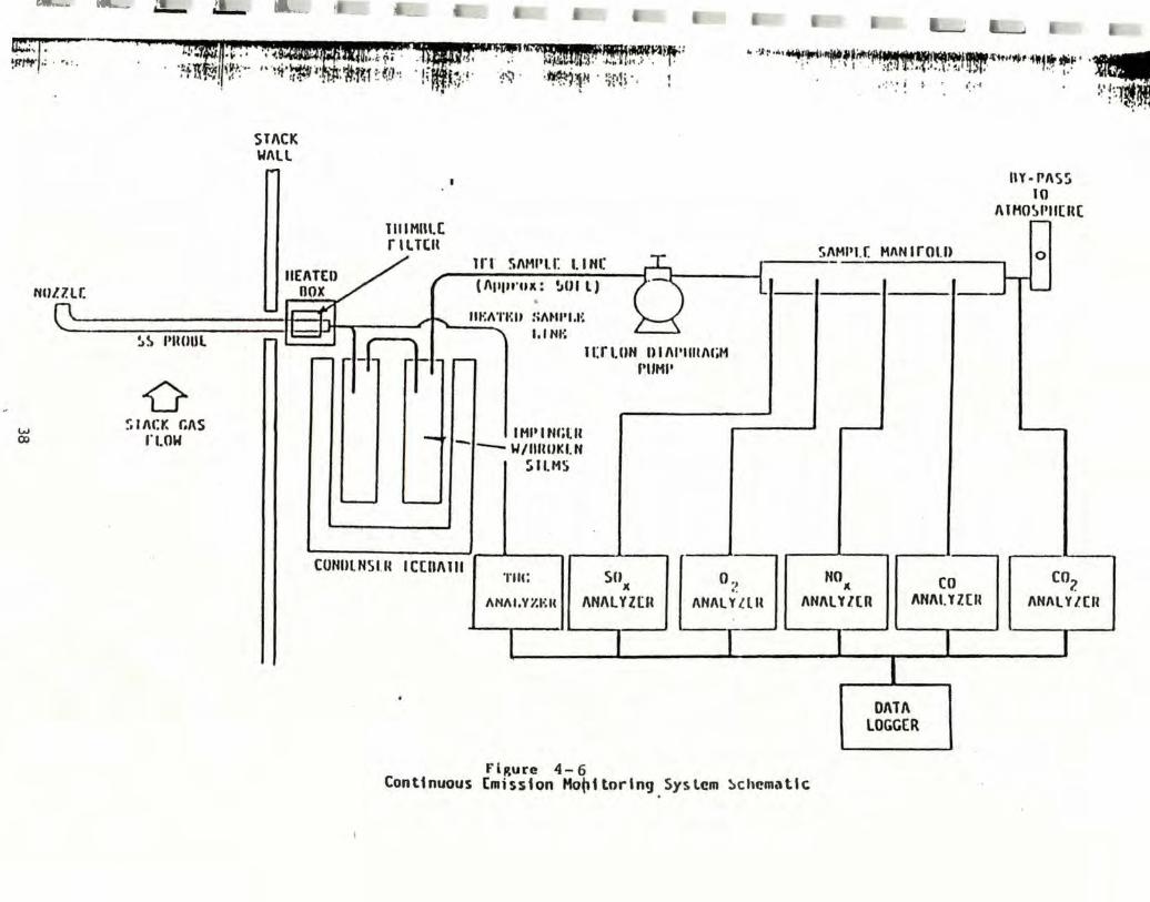
4.1.6 Continuous Emission Monitoring of NOz, SO 2 , CO, THC, 02 ,
and CO2
Continuous emission monitoring (CEM) will be performed at the exhaust stack to determine concentrations and emission rates of NO., S02, THC and CO. Diluent concentrations of 02 and CO2 will also be monitored. A schematic of the CEM system is presented in Figure 4-6. Although this data will be collected throughout the test program, Norlite will also monitor CO concentrations with • their in-plant CO analyzer. · These data will be used to establish a CO emission limitation.
All CEM data will be recorded using an automatic digital data logger or on-strip charts. The CEM system will be housed in a laboratory at the base of the exhaust stack.
Sample Conditioning System
A heated (250°F) Alundum thimble filter will serve to remove large particulate matter from the sample gas stream. The thimble filter will be mounted on the back end of a heated (250° ±25°F) stainless steel sampling probe with a stainless steel nozzle facing away from the stack gas flow. The sample stream is then drawn through heated (300°F nominal) teflon sample line to two standard Greenburg-Smith type impingers (with impingement stems broken off) immersed in an ice-bath to remove the moisture from the gas stream. The sample is then drawn through Teflon tubing by a leak-free Teflon double diaphragm pump to a stainless steel sample manifold with an atmospheric by-pass rotameter. The NO.,
, S02, CO, 02 and CO2 analyzers draw samples from this manifold • .
36
l l , 1 ,
I l I l ,
l
j ..
l -~-·~ .. ~.·~·
i • . I ! I 11
ft( i u-;...----
k) I I
Cl);' Iµ, ~ <:~,~---_-_-_ -_ -_-_ ...J__J
~\H ~-r8 I n
·- . '· ...
UJ al 0 a: a.
--.:.--~ 1--- -----==· =----- - --l
.s f 1-
.s -Q.
~ tr) cl)
"' ~ 'O 0 ... l'O e, c., ~
C:
Ill I ~
:.u ,...
I§ ,.,_ -
---er.-" !;..,.,-i,: . •. , .
w CX)
NIJlll(
~
--- ~
~~ l'llUUl
0 ~11\C:Y. f./\S
fl.OW
.:.,_ ... __
... 4,B:
" i1t·~1; • . 1 •tr,,.., tN'-lt ~ ,.~• · . . .
STACK Wl\ll
TII IMUI.C rllTClt
. ~ 11:f.¥~ 9,IIIA~~~.ft-;: . . J; llJJ.\T. :;::;:H1, .• . I: ·;i,~ • ;_~ _'.Iii,. • ::r,1,; •, • , n;'"i; .... , .-., ~ , .. ,
' .
Tri !il\Ml'I.I: I.I NI:
( /\111,rox : !,CH l) •
m :A'l'lm :i/\t-11'1,I•: I, ltll•:
IHlttNf;tn -•- 1-1/IIIUJKI.N
SILMS
1 U l.UN U I /\1'1111/\GM l'IIMI'
" ·•J~•••~~l••f·~~~-J&'i~••#ritf't!li~ ' •~ '. . . 1 , · . • · :-r. in ~.~t:i.,1 . . , l;.IF . ,.
' ·'·'· . i • ' ,· ... , • •,• J .. 'tfll . . . ' . , . . •. : :·1~ .
SI\Ml'I.( HI\N lrOI.I> .----
I\Y·PI\SS 10
AIHOWIICH(
CUNUlNSl.1{ IC[IIAIII SU O ., NO CO CO2 gGg ANAL;m, AHALY·w, ANALv•,rn ANAI.YllR Qvirn
TIii:
/\N/\l,Y1.l-:I<
-- . .
DATA LOGGER
FlRure 4- 6 Continuous [mission Mot,1 torln9 System ~cht?matlc.

•
•
i J
The total hydrocarbon analyzer draws unconditioned sample through a heated (250°F) teflon sample line •
Continuous Emission Analyzers
Emission parameters to be continuously analyzed are NOx, S02 , CO, 02 , and CO2 • NOx concentration will be monitored in accordance with EPA Method 7E adapted for this source. S02 concentrations will be monitored in accordance with EPA Method 6C. CO concentrations will be monitored in accordance with EPA Method 10. 02 and CO2 concentrations will be monitored in accordance with EPA Method 3A.
A Siemens Model Ultramat SE nondispersive infrared gas analyzer or equivalent will be used to continuously monitor emissions of CO. The analyzer operates on the measurement principle based on co having a known characteristic absorption spectra in the infrared range. It contains an infrared detector that uses the . nondispersive single beam technique with alternate modulation of the sample and reference cells. Radiation absorbed by CO in the sample cell produces a capacitance change in the detector which is proportional to the CO concentration.
A Thermo-Electron Corporation Model lOA Chemiluminescent NO/NOx gas analyzer or equivalent will be used to determine NOx emission concentrations. The chemiluminescent reaction of NO and 03 (ozone) provides the basis for this analytical method (NO+ 03 -> N02 + 02 + hv). A Western Research Model 721 S02 analyzer or equivalent will be used to determine S02 concentrations in the stack gas. This instrument utilizes the ultra-violet photometric principle and was designed to meet the stringent requirements of CARB to ensure maximum accuracy and reliability, without NOx interference, in the 0-1000 ppm and 0-100 ppm S02 ranges.
A Ratfisch Model RSSS Total Hydrocarbon Analyzer or equivalent, which utilizes a flame ionization process with associated pneumatic and electronic components to analyze and measure, as carbon, hydrocarbons C1 through C18 , will be used to determine kiln exhaust voe concentrations in accordance with EPA Method 25A. A small amount of sample containing hydrocarbons is introduced to the system through a heated filter and sample line. The sample gas flows through various lines, _ filters, and valving by the use of a heated sample pump. The sample gas then enters the heated detector bench, which contains the flame ionization detector (FID). Flame ionization is a process of continuously creating ions by a flame. Upon combustion, hydrocarbon and carbon atoms are separated into positive ions and free electrons. The positive ions are attracted to the burner (negative); the free electrons are attracted to the collector cylinder (positive). An electron flow is established from the burner to ~he_col;ector cylinder. The flow is proportional to the 1on1zat1on process created by the flame. The resulting current
39

is detected and amplified by an electrometer/amplifier circuit. The output of the amplifier provides a signal for direct readout on a meter indicator or for outputs to a recorder or computer.
A Siemens Model Oxymat SE oxygen analyzer or equivalent will be used to determine concentrations of 02 in the stack gas. This instrument utilizes the paramagnetic principle, which comparatively measures the magnetic susceptibility of a gas volume by the force acting upon a non-magnetic test body suspended in a disproportionate magnetic field. Output current is proportional to the oxygen concentration linearity.
An Infra-Red Industries, Inc. infrared CO2 analyzer or equivalent will be used to monitor CO2 emissions. This instrument operates on the principal of CO2 having a known characteristic absorption spectra in the infrared range. Radiation absorbed by CO2 in the sample cell produces a capacitance change in the detector which is proportional to the CO2 concentration.
Data Acquisition and Handling
All CEM data will be monitored by a automatic data logger which will record data with its integral printer. Trends will be monitored using the strip chart mode for co, 02 , CO2 and stack temperature, with averages printed digitally for 30 minute intervals and/or the test period. Emission data will be "viewed" by the data logger at 5 second intervals. This will enable realtime emission data to be available on site.
Stratification Check
Prior to the CEM system coming on-line for the trial burn, a stratification check will be performed at th_e sampling location. Twenty-four traverse points as described in Section 5.1 will be sampled for CO and oxygen to detect the presence of stratification of these gases and to determine a point of average concentration for sampling. The Norlite CEM system shall be used as the point of reference. The CEM probe will then be positioned at the point of average concentration for the remainder of the test program. Based on past experience, stratification is not expected.
CEM System Calibrations
Calibrations of the CEM system will be performed at the beginning and end of each test using either EPA Protocol 1 and/or NBS Traceable calibration gases. Calibration gases (zero, mid-range and span) will be introduced to the CEM system through a 3-way heated valve located at the back of the sampling probe. Each analyzer will also be multi-point calibrated prior to the trial burn to establish instrument linearity. A three point calibration of each analyzer, along with system leak and bias
40

checks, will be performed at the beginning and end of each test day. Zero and span calibrations of each analyzer will then be performed between each test.
4,1,7 Opacity
The opacity of the exhaust plume will be determined in accordance with EPA Method 9 during each PM and HM tests performed. The observer will position himself in accordance with the method taking into consideration plant operations and traffic patterns. Data will be recorded at 15-second intervals throughout each test and reduced to 6-minute averages of 24 consecutive readings.
4.2 Combustion Efficiency
The combustion efficiency of the kiln will be determined using average CO and CO2 concentrations measured at the back of the kiln for a given test period. This calculation will afford a comparison of combustion efficiency (CE) verses Destruction and Removal Efficiency (DRE). The following equation will be utilized.
% CE=% CO2 - % CO x 100 \CO2
4.3 Kiln Outlet Plowrate, co, CO2 and 02 Measurements
Volumetric flowrate at the kiln outlet will be determined in accordance with EPA Methods 1 and 2 during each test. In addition, an integrated gas sample will be drawn from the kiln outlet simultaneously with each integrated gas sample drawn from the stack for analysis to determine CO, CO2 and 02 concentrations in accordance with EPA Methods 3, 3A and 10. A comparison with co, CO2 and 02 concentrations measured at the stack will reveal any ambient air leakage into the system, allow for the correction of gas concentrations, and enable the calculation of kiln residence times. The sampling train used is shown in Figure 4-5.
4,4 Raw Material and Product Samples
Samples of raw materials (raw shale, coal, scrubbing caustic solution and makeup water, lime and LGF) and product (clinker, scrubber blowdown and collector dusts) will be taken during the trial burn to evaluate possible contamination and to perform a chloride and metals mass balance on the kiln. Samples will be drawn on a grab sample basis at the beginning and end of each test and composited for all parameters except the LGF and blowdown. The LGD and blowdown will be collected by a continuous drip sample.
41

-
• •
_I
LGF, coal, clinker, makeup and caustic feed water and contaminated liquor (blowdown), raw shale, lime, multiclone dust and baghouse dust samples will be analyzed for heavy metals by atomic absorption or ICAP, for POHCs using GC/MS Method 8240,. and for total chloride using the ASTM silver nitrate titration methodology. Coal and LGF samples will also be subjected to ultimate and calorific analyses. LGF samples will be analyzed for POHCs, total chloride, ash, solids, viscosity, and heavy metals.
LGF and scrubber blowdown will be drawn using Method S004. This method is designed for collecting integrated liquid samples from moving streams. All samples drawn for POHC analyses (LGF, dust, lime, liquors and clinker) will fill the container (no headspace) and will be kept on ice until analyses. LGF samples will be split and an aliquot given to DEC for analysis.
· One glass sample jar will be .filled at each of the following sample locations as shown in Figure 3-1. Samples will be composited by test run as drawn and split for shipment to laboratories.
Raw Materials
o Raw Shale Feed Belt o Coal Feed Belt 0 LGF Feed Line o Caustic Feed Liquor Tank o Makeup Water Tank o Lime Injection Line o Metal Spiking Compounds
Product
o Multiclone Discharge Hopper o Baghouse Discharge Hopper o Scrubber Slowdown Pipe o Cooler Conveyer
Raw shale samples will be drawn from the feed conveyor immediately preceding the back end of the kiln at the beginning and end of each test run. A total of 12 composite samples will be drawn from this location, all of which will be analyzed for total chlorine, six of which will be analyzed for POHC (samples drawn during VOST tests) and six of which will be analyzed for heavy metals content.
Coal samples will be drawn during the coal fired tests from the belt feeding the coal pulverizer. A total of six samples will be drawn and analyzed for heavy metals, ultimate, calorific and total chloride values. Three samples will be analyzed for POHCs.
42
. I l I

LGF samples will be drawn on a continuous basis throughout each test from a tap in the feed manifold immediately preceding injection into the kiln. Samples will be drawn using Method S004 utilizing a continuous drip and a submerged fill pipe to ensure an integrated sample over the course of the test. The sample container will be immersed in ice during the sample pe r iod to prevent volatiles from escaping. A total of three composite samples will be drawn, all of which will be analyzed for total chloride, viscosity, solids, ash and BTU. Three samples will also be analyzed for POHC content (those drawn during t he VOST tests), while the other three (drawn during the particulate and metals tests) will also be analyzed for heavy metals content.
Lime, caustic feed and makeup water samples will be drawn at the beginning and end of each test. A total of twelve samples will be drawn from each source. Six samples will be analyzed for heavy metals and total chlorides, while the other six will be analyzed for POHC and total chloride.
Dust samples from the multiclone will be drawn from the hopper at the beginning and end of each test run. These chutes will be temporarily blocked during the test program to allow enough dust to accumulate to collect a sample. Dust mass flowrate will be quantified using a stop watch and a tared bucket. A total of 12 composite samples will be drawn at this location and analyzed for total chloride. Six samples will be analyzed for POHC and six for heavy metals.
Dust samples from the baghouse will be collected and analyzed in a manner identical to that used for the multiclone. Samples will be drawn from the hopper screw conveyor at the beginning and end of each test run. A total of 12 composite samples will be collected and analyzed as described for the multiclone.
Blowdown liquor samples will be drawn from the discharge pipe using Method S004 during each test. A total of 12 composite samples from each unit will be analyzed for total chloride while six samples will also be analyzed for POHC and the other six for heavy metals.
Clinker samples will be drawn at the discharge belt of the clinker cooler. A total of 12 composite samples will be drawn and analyzed for total chloride. Six samples will also be analyzed for POHC and the other six for heavy metals to correspond with emission samples.
Metal spiking compounds will be analyzed separately to confirm the assay on metals of interest.
43
•

w j
5.0 SCOPE OF THE SAMPLING PROGRAM BY SITE
The trial burn test matrix is sho'Wl1 in Table 5-1. Two series of tests will be performed {Background and LGF Trial Burn) to _ determine the acceptability of firing LGF in the kiln. Sampling will be performed in the exhaust stack to determine emissions of POHCs, particulate matter, HCl, Cl2, NOK, S02, co, THC, 02, CO2, and heavy metals. Sampling will be performed at the kiln outlet to determine concentrations of co, CO2 and 02• Raw material and product samples will be taken for POHC, heavy metals, and total chloride analysis. If desired by NYSDEC, three additional particulate runs will be performed as a third test condition while the baghouse is operated on two modules.
5.1 Stack Emission Samples
Stack emissions will be sampled through two ports located 90° apart in the 60 inch ID stack. The ports are 10 feet (2.0 diameters) do'Wnstream from the scrubber and 10 feet (2.0 diameters) upstream from the top of the stack. Twenty four traverse points will be sampled at this location for particulate and metals as shown in Figure 5-1. Two additional sampling ports located at approximately the same level will be used for HCl sampling and continuous emission monitoring of CO and 02•
5.1.1 POHC Emission Measurements
POHC emission measurements utilizing the EPA SLOW VOST procedure will be performed at the exhaust stack. Single point samples, 40 minutes in duration, will be taken at· a point approximately centered in the stack. POHC measurements will be made at the two proposed test conditions. Four VOST runs, each utilizing one pair of cartridges, will be performed during each test. A total of 6 tests will be performed (3 coal and 3 LGF) requiring 24 cartridges. One set of field and trip blank cartridges will be taken for each test condition. A velocity traverse shall be performed concurrently with each test performed in accordance with EPA Methods 1 and 2 to determine the exhaust volumetric flow rate.
44

' ' I l
l -i I -l .
. · .. -~ -~ ... ~
~ I . -- -: ;;: --- , . -~.";;{ .... ~
:I · - ·-· - · ·
-·
·1 ~
'1
. j
.u
.J J
i ]
l ~ ~
i
i :
~--
. . -· -. - -· . .. .
I
-
I i '◄ so·~ I ' I '
I j
I . T . o r; ,
·-:-: . . ..
TRAVERSE DISTANCE FROM POINT INSIDE WALL
. . - _,. . 1 . 1.3 2 4 3 ·. 7.1 . . - . .. - ~;.. -. . .. ;.•
4. -· 10.6· --SCRUBBER s- · 15
~ 21.4 7 · 38.6 8 45 9 49 .9 10 52.9 1 1 56 12 58.7
Figure s-1 Sampling Pert and Traverse Point Locations Ncrlite Ccr;cra ticn, Cohoes, NY .
. · 1 ...
. I
. . . .. . . . -

IL.
,i:,. Q'\
A-.. L , ,--,·-r ~ -' L]'_. _ ~--· --~·
Tab.l!.,j,:_l
PROPOSED TEST MATRIX FOR BACKGROUND AND TRIAL BURN TEST RUNS KILN NO. 1
NORL ITE CORPORA Tl OH COHOES, NEW YORK
S~l• Total Particulate HCl/ sanplJoa Location !1!J.tiA fQ!!.£i Chloride Mettee il2
Stack exhaust gases 6 . 6* 6
Kiln <>.itlet exhaust gases . . . . Hulticlone Hopper dust 6 6 . . Baghouse Hopper dust 6 6 . . Scrubber Feed caustic solution 6 6 . . Hoke Up city water 6 6 . Scrubber Blowdown brine 6 6
Lime Feed lime 6 6 . . Cooler Conveyor product 6 6 . . Shale Feed Belt raw shale 6 6 . . Cool Hill coal 3 3 . . LGF Feed Line l !quid waste 6 6 . City Water water 3 3 . .
* Note: If desired by NYSOEC, three additional PH tests can be performed while the baghouse is operated with two of the three modules.
Cr Gas t!£!!!1 :t.l ll2!!
6 3 12
. . 12
6 6
6 6
6 6
6 6
6 6
6 6
6 6
6 6
3 3
6 6
3 3
W! Q.c.Ul
12 6
12 6
Opacity
6
L_. .__'.
Viscosity BTU. Ash, Solids
3
6

I • s,1,2 Particulate, HCl, Heavy Metal, Hexavalent Chromium and Emission Measurements
Particulate, hexavalent chromium and metals sampling will be performed at 24 traverse points in the exhaust stack. Hydrogen chloride and chlorine sampling will be performed at a single point in the exhaust gas. Each point will be sampled for 3 minutes for a total test time of 72 minutes. A total of 6 of these test runs (3 at each test condition) will be performed using sampling and analytical methods described in Section 4.
5,1.3 CO2 and 02 Integrated Gas Measurements
Integrated gas samples will be drawn through a probe integral with the particulate sampling probe at 24 traverse points simultaneously with each test described in Section 5.1.3. Sampling and analysis will be in accordance with EPA Method 3 as described in Section 4. A total of 6 samples will be drawn and · analyzed.
5,1.4 Continuous Emission Monitoring
Continuous emission monitoring will be performed to determine emission concentrations of NOx, 502 , co, THC, 02 and CO2 by extracting a sample stream through a sampling port in the stack. Monitoring will be performed continuously, concurrent with all manual emission testing. Calibrations, as well as system leak and bias checks, will be performed at the beginning and end of each sampling day.
5.1.S opacity
The opacity of the scrubber exhaust stream will be mon i tored concurrently with each PM/HM test performed in accordance with EPA Method 9. Six test runs 72 minutes in duration wi l l be performed, three tests under each test condition.
5.2 Kiln Outlet Flowrate, CO, 02 and CO2 Measurements
Integrated gas samples will be drawn from the kiln outl et during each emission test performed at the stack. A total of 6 samples will be drawn and analyzed in accordance with EPA Methods 3 and 3A as described in Section 3.3 in order to provide a measure of air in-leakage across the air pollution control system. Kiln gas flowrates will also be determined at this location during each test in order to calculate residence times.
47

5.3 Raw Material and Product Samples
Samples of raw material and product will be drawn at the beginning and end of each test run and composited for the test period. LGF and scrubber blowdown liquor samples will be drawn on a continuous basis throughout each test. A glass sample jar will be filled with sample from each of the following locations:
o Raw Shale Feed Belt o Coal Feed Belt o LGF Feed Line o Lime in Injection Line o Caustic Feed Tank o Multiclone Discharge Hopper o Baghouse Discharge Hopper o Scrubber Blowdown Pipe o Clinker Cooler Conveyor
Further details of this sampling are presented ·in Section 4.
5,4 waste Selection
The following waste types will be selected for use during the trial burn to demonstrate that the permit objectives delineated in Section 2 can be met. These feeds will be choien to be similar to those fed during the 1989 and 1990 trial burns.
The LGF feed will consist of a solvent waste stream or LGF designated D00l and/or F00l-F00S. This stream will be sp · ked with halogenated material. The characteristics of the spiked stream are delineated in Table 2-1. This stream is a pumpable liquid mixture of a viscosity of no greater than 3000 SSU.
5,4.1 Metal Spikes
The LGF waste used in the test burn will be spiked with metals to bring the waste blend characteristics to the level indicated in Table 2-1. The source of the metal spikes will be from manufactured products of known quality and composition. Tables-2 lists the proposed spike compounds. These materials may be changed later based on availability, compatability or miscibility with the specific waste streams to be tested.
48
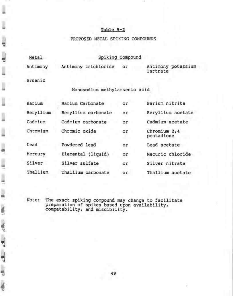
:.. . .:.;
I... J
~ J. f..e__
Metal
Antimony
Arsenic
Barium
Beryllium
Cadmium
Chromium
Lead
Mercury
Silver .
Thallium
Table 5-2
PROPOSED METAL SPIKING COMPOUNDS
Spiking Compound
Antimony trichloride or Antimony potassium Tartrate
Monosodium methylarsenic acid
Barium Carbonate or Barium nitrite
Beryllium carbonate or Beryllium acetate
Cadmium carbonate or Cadmium acetate
Chromic oxide or Chromium 2,4 pentadione
Powdered lead or Lead acetate
Elemental (liquid) or Mecuric chloride
Silver sulfate or Silver nitrate
Thallium carbonate or Thallium acetate
Note: The exact spiking compound may change to facilitate preparation of spikes based upon availability, compatability, and miscibility.
49

i • I
~ J
j ~
~
l .,
The metal spiking compounds will be blended with the LGF feed by dissolving or suspending the compound to the approximate concentration given in Table 2-1. Metal spiking procedures will be similar to those used by EPA during field validation of metals testing methodology on full scale incineration systems prior to the final BIF rule (see EPA Project Report No. DCN-89-232-011-034-36).
Tables 5-3, 5-4 and 5-5 present the net feed rates for LGF, coal and metals for test condition A and B respectively.
Runs 1,2,3 - Condition A - No LGF, coal fuel only
Runs 4,5,6 - Condition B - LGF
Runs 7,8,9 - Condition C - Optional particulate test only while operating two of three baghouse modules (based on NYSDEC's request).
All thermal inputs for all runs and test conditions will be approximately 62 million BTU/hr. Shale feed rates for all runs will be 22 tons/hr.
so

.I
J
-i I
Table s-3 TEST CONDITION A
No LGF Feed, Kiln fired on Coal only
Table 5-4
TEST CONDITION B
Feed Rates, lbs/hr
Shale Liguid
Mass 44,000 4,800
Antimony 0.0088 0.960
Arsenic 6.86 0.240
Barium sr:o 2.88
Beryllium 0.132 0.0058
Cadmium 0.152 0.144
Chromium 3.00 6.72
Lead 2.78 5 . 23
Mercury 0.035 0.22
Silver 0.132 2.40
Thallium 0.0881 1.4 4
Halogens 0.836 144
The blended LGF will be sampled during each run, from a sampling tap in the feed line to the burner. All samples from each run will be composited.
51

• 5,4.2 POHC Spikes
The POHCs will be spiked into the LGF feed, to result in a total • halogen content of not more than 3\. The approximate r concentration of the three POHCs required to arrive at this level
of halogen are tabulated below:
.;.
; ~
~J t 1
~·1
~-I -~~
d ,1 f; --.,
EQHC.
carbon tetrachloride
1,1,1-trichloroethane
perchloroethylene
s.s Test Schedule
LGF, ' 3.25
3.75
3.50
This Supplemental Trial Burn Program is scheduled to take place over a two-week period beginning the second week of June, 1992. An outline of the proposed schedule is presented in Table 5-6, subject to modification.
All testing is proposed to be performed over a 10 to 12 hour day. Delivery and preparation of the trial burn fuel will be performed during the coal-fired tests. Additional meetings may be scheduled as required. Any modifications to this schedule will be presented as an addendum to this protocol.
52
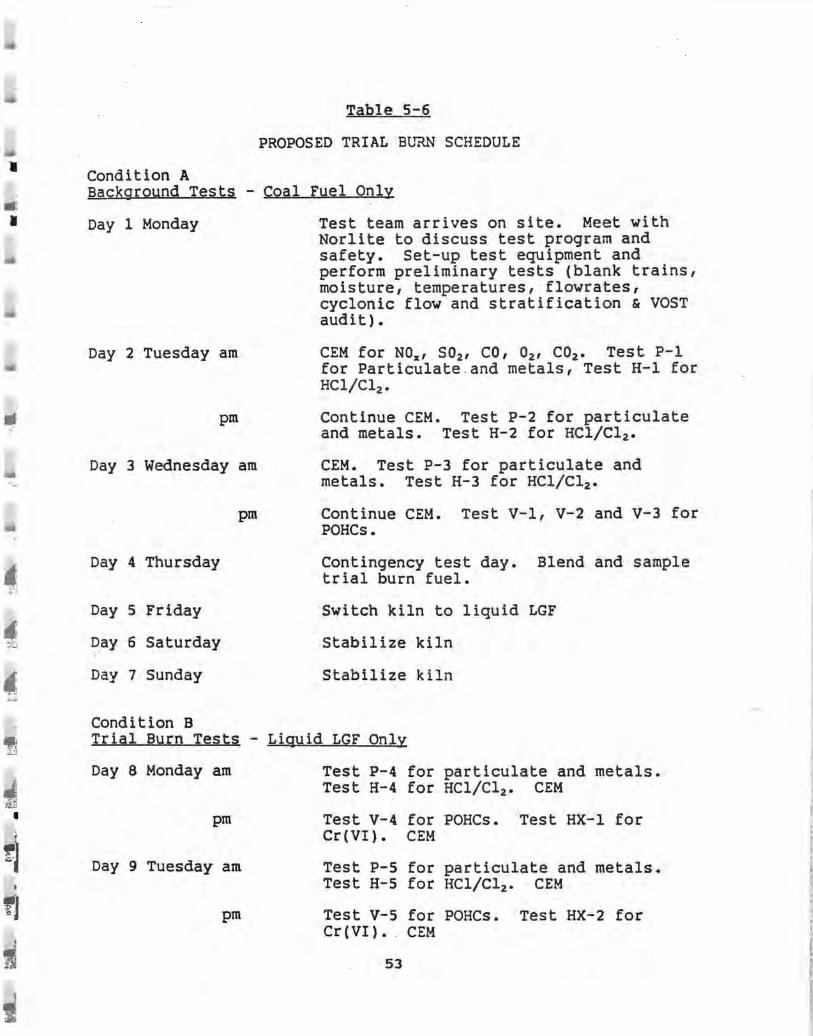
• • •
IP! ~J
I
l
1
Table 5-6
PROPOSED TRIAL BURN SCHEDULE
Condition A Background Tests - coal Fuel Only
Day 1 Monday
Day 2 Tuesday am
pm
Day 3 Wednesday am
pm
Day 4 Thursday
Day 5 Friday
Day 6 Saturday
Day 7 Sunday
Condition B
Test team arrives on site. Meet with Norlite to discuss test program and safety. Set-up test equipment and perform preliminary tests (blank trains, moisture, temperatures, flowrates, cyclonic flow and stratification & VOST audit).
CEM for NOx, S02 , CO, 02 , CO2 • Test P-1 for Particulate . and metals, Test H-1 for HC1/Cl2 •
Continue CEM. Test P-2 for particulate and metals. Test H-2 for HC1/Cl 2 •
CEM. Test P-3 for particulate and metals. Test H-3 for HC1/Cl2 •
Continue CEM. Test V-1, V-2 and V-3 for POHCs.
Contingency test day. Blend and sample trial burn fuel.
Switch kiln to liquid LGF
Stabilize kiln
Stabilize kiln
Trial Burn Tests - Liquid LGF Only
Day 8 Monday am
pm
Day 9 Tuesday am
pm
Test P-4 for particulate and metals. Test H-4 for HC1/Cl2 • CEM
Test V-4 for POHCs. Test HX-1 for Cr(VI). CEM
Test P-5 for particulate and metals. Test H-5 for HC1/Cl2 • CEM
Test V-5 for POHCs. Test HX-2 for Cr (VI) • . CEM
53
I
•
i!
ti J
a:] £
◄ ~
·;J .~ ~ :a .
~ "" .
1 ~ -i 1
Day 10 Wednesday am
pm
Day 11 Thursday am
pm
Day 12 Friday
Test P-6 for particulate and metals. Test H-6 for HC1/Cl 2 • CEM
Test V-6 for POHCs. Test HX-3 for Cr(VI). CEM
Test P-7 and P-8 for particulates while operating 2 of 3 baghouse modules
Test P-9 for particulate while operating 2 of 3 baghouse modules.
Contingency/demobilize
54

il
6.0 QUALITY ASSURANCE
The project manager is responsible for implementation of the quality assurance program as applied to the project. The QA program is designed to ensure that emission measurement work is performed by qualified people using proper equ i pment following written procedure in order to provide accurate, defensible data.
6.1 Sampling Quality Assurance
Generally, implementation of quality assurance procedures for source measurement programs is designed so that the work is done:
1.
2.
3.
By competent, trained individuals experienced in the specific methodologies being used.
Using properly calibrated equipment
Using approved procedures for sample handl ing and documentation.
Measurement devices, pitot tubes, dry gas meters, thermocouples and portable gas analyzers are uniquely identified and calibrated with documented procedures and acceptance criteria before and after each field effort. Records of all calibration data are maintained in the files.
Data are recorded on standard forms. Bound field notebooks are used to record observations and miscellaneous elements affecting data, calculations, or evaluation.
Prior to the test program the testing company provides the following:
1.
2.
3.
Filter numbers and tare weights of all filters available for the test.
The results of reagent blank runs on the reagents to be used during the test.
Calibrations of all pitot tubes, dry gas meters, orifice meters, sampling nozzles, and thermocouples which are to be used during the test. Dry gas meter systems are audited for accuracy in the field by the use of a critical orifice (Method 5). All calibrations are performed within four months prior to the test date.
4. All sampling trains are checked for leaks, prior to and at the end of each test run.
Specific details of the sampling QA program for stationary air pollution sources may be found in "Quality Assurance Handbook for
55

I
I
Air Pollution Measurement Systems", Volume III (EPA-600/4-7-027b). .
6.1.1 EPA Methods 1,2,4,5, and 0051 Multiple Metals Sampling · Train and Hexavalent Chromium Sampling Train {Section 3.0 and 3.2 of EPA/530-SW-91)
All particulate and metals sampling will be 100\ +/- 10% isokinetic. Probe and filter temperatures will be +/-25°F of the specified temperature.
Prior to sampling, a clean-up evaluation of each sampling train will be performed to ensure the accuracy of the sampling equipment and to determine the level of background contamination (if any). A clean-up evaluation will be performed on each set of glassware to be used in the test program. These tests will be performed prior to testing on each fuel type and upon the conclusion of testing in the sample recovery area and observed by NYSDEC if desired. The sampling train will be precharged as if ready to test and then recovered and analyzed as specified for the actual test program. Results will be included in the final report. In summary, these evaluation tests are designed to precondition the sample train, establish background values, evaluate sample recovery, efficiencies and educate sample recovery personnel in the specific procedures.
In addition to the above, three blank samples of each collection media (reagents and filters) will be collected at the test site for background analyses. All clean-up evaluation and blank samples will be analyzed in conjunction with actual test samples. Sampling results will be corrected for these backgrounds if required. All blanks shall be taken and analyzed in accordance with procedures specified in the EPA Methods referenced above.
Appropriate sample recovery data will be recorded on the sample identification and handling logs, chain of custody forms and analytical data forms as presented in the Appendix.
Recovered samples will be stored in shock-proof containers for storage and shipment for analyses.
6.1.2 CEM System
The CEM system will be calibrated at the beginning and end of each test and leak and bias checked daily. All calibration gases will be either NBS certified or EPA Protocol l. Multi-point calibrations will be performed on each analyzer to establish linearity prior to sampling and then throughout the test program.
56
-
-~ i
•; ~-
6.1,3 VOST Method
Fiel d Blanks - Blank Tenax and Tenax/Charcoal cartridges will be taken to the sampling site and the end caps removed for the period of time required to exchange two pairs of traps on the sampling train (approximately 5 minutes). After the two traps have been exchanged, the end caps will be replaced on the blank tubes which will be returned to storage on ice until analysis. One pair of field blanks shall be included with each set of 8 VOST cartridge pairs collected.
Trip Blanks - One pair of blank cartridges (Tenax and Tenax/Charcoal) shall be included with shipment of cartridges to the site. These blanks will be treated as any other cartridge except that the end caps not be removed. These cartridges will be analyzed to monitor potential contamination which might have occurred prior to shipment.
Audit - Audit gas provided by NYSDEC will be sampled in accordance with the instructions and samples analyzed along with the actual samples during the Trial Burn.
6.2 Analytical Quality Control
The analytical laboratory must maintain a vigorous quality control program for all samples analyzed. This program is based on the general guidelines given in "Handbook for Analytical Quality Control in Water and Wastewater Laboratories" (EPA-600/4-79-019, March 1979) and Chapter 1 of EPA's analytical manual SW846. This program suggests guidelines in the areas of:
o Laboratory services o Instrument selection o Glassware o Reagents o Solvents o Gases o Analytical performance o Replicate and matrix spike analyses o Control charts for tracking precision and accuracy o Instrument calibrations o Reagent blanks and field blanks
6.2 . 1 VOST Method
The analytical laboratory will spike all Tenax and Tenax/Charcoal cartridges with internal standards to monitor recovery efficiencies and laboratory performance. To establish the ability to generate acceptable accuracy and precision, the analytical lab will spike blank cartridges with the analytes of interest (surrogate POHCs) at two concentrations in the working range. The avera~e percent recovery and the standard deviation
57

•
•
•
for each will then be calculated. The average recovery and standard deviation must fall within the expected range for determination of volatile POHCs using this method (SO\ to 150\) •
In addition, audit samples provided by NYSDEC and US EPA will be analyzed in a manner identical to that used for the actual emission samples •

• ~ ;.
---1 Ii
l ., -~ •:I ·i -~ .
APPENDIX 1
TESTING FORMS
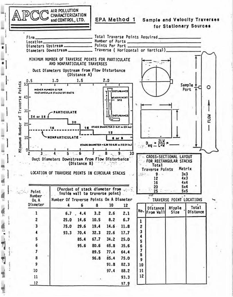
/A)f)(C(C AIR POLLUTION
D CHARACTERIZATION and CONTROL, LTD. EPA Method 1 Sampl e and Velocity Traveraes
for Stationary Sources
~l .. l ~
!J ' -~
1 ~ .M
Firm __________ Total Traverse Points Required _______ _ Location Number of Ports _____________ _ Diameters Upstrea111 Points Per Port ____________ _ Diameters Downstream Traverse ( Horizontal or Vertical) _____ _
HINIHUH NUMBER Of TRAVERSE POINTS FOR PARTICULATE ANO NOHPAATICULATE TRAVERSES
. Duct Diameters Upstream from flow Disturbance (Distance A)
r "' o.s 1.:> J.5 2.0 ~ 5'.) C: -0
Q.
Cl 4()
"" '-~ > r.l
'- 30 I-~
0
t 20 § .E e 10 :::, e . :::,
Hl~U IIIUMIIII IS •o• a1cu,,11cuv.a STACEJI o• ouas
PAIITICUUTE 2, or 215
20 11 1 8 ST AC& OUMUU > U1 • Qt .J
---------------·•--t--~ ~ 1Z '-,.NONPARTICULATE .-•-----,--,-o,-1--c
IT.IC& CKoUCTta • Lll 10 La • "J.Zt .J
l ..._________. l
.!: · 0 . .. .
x: 2 . · 3 4 · S · . .. 6 7 8 - g. 10 ..----------..
... . . . . . --~ .. :· .. :
· • . · · · • '="· . .. . • ·· ··• · tr. CROSS-SECTIONAL LAYOUT . Duct Diameters Downstream from flow Disturbance". :· · _.·. FOR RECt•uGULAR STAC"C!
. (Distance B) . ;. ·· :; __ ·_:-=---~ .'. , . Totall\ll -
LOCATION .OF TRAVERSE POINTS IN CI~CULAR STACKS
Point . . (Percent of stack diameter from ... -~ .. .-; inside wall to traverse point) . - ·: Humber ··
On. A Number Of Tr•verse Points On A Diameter Diameter 4 6 8 10 12
1 6.7 . 4.4 3.2 2.6 2.1 2 25.0 14.6 10.5 8.2 6.7 3 75.0 29.6 19.4 14.6 · 11.8 4 93.3 70.4 32.3 22.6 17.7 s 85.4 67.7 34.2 25.0 6 95.6 80.6 65.8 35.6 1 89.5 77.4 64.4 8 96.8 85.4 75.0 9 91.8 82.3
10 97.4 88.2 11 93.3 12 97.9
Traverse Poin~s . Matrix 3x3 4x3 4x4 5x4 SxS
.::,._;..,,_ .·. g.
No.
1 2 3 4 5 6 7 8 9 10 1-1 12
12 16
.. 20 -.· 25
~ TRAVERSE POINT0
LOCATIONS - I
Dfstance Nipple Total from \lall Size • Distance
0
t
....
··I

- ---··----- - --
1 &IPCCCC ~-:. :-~-t:D ? AIR POLLUTION
CHARACTER!ZA TION -1 ANO CONTROL. LTD. ·,'E!..X!''Z"'i 7?.., \':?.s: .~:rJ :=t04'RA,:. ::i::1:::t'll:~::s
I 1
I ~~-------------~~-------------t.OCATIO!'f ------------~ St.\CI DO!e6I(JG _____ ~ _____ fi:.· WO-ElUC ?RfSSlR:, ~ • ________ in. Ha
STACI STA!IC PRESS.IRE, Pi • : in. HzO STJa GAS ,.DLECl.JLJJl 'lr:IGiI' (Vet), "t.t _____ _
ST>.CI GAS l-OISiURE c:::NI?n', I KzO •------- sc-ew..rrc OF iit'\':?Sa POU.T ~~ . • El ....,oc.XWlH
PilOT ~- ---- ---~------1:.:)1::A _____________ _ Cyc.!cnic: f1011 An1le • 9 C:ll.lnte:-c.!oci:lrJ
~ .i
"" I . ,. ~ ) · : · . .
i.~~ . ) I~:
~l .:::..c!
■: l ~
s j ! ' 1
,..~ /J .
I ~
1
I I :.P ..r;;1 I ~~ I I :.!:~r;;:~ l p . ens a . PORJ' POL\T Inch HzO : 9
I I I i I ;
I I I I '· I !
I I i I I I I 1- I ' I '
I I I r I I I I I I I I I I I
'- I l--·-+---+l----l------if----t--1 --f--------j!;---·• ~ I
I . ... . .
.
I I I I I I I I I I I I I I I I I I I I I I I I I I I I I I Avenp I !Ts•
t:1
I l~ I 1-~ I
OF •
-
I I I I I
•.,VJ. of absolute values illcludini :eroes
I I I I I I I I
I ! I
- I I
i I I I i I
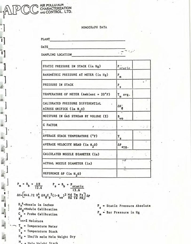
~ D CHARACTERIZATION · cccc AIR pOLL\JllUN .
~IJ) """ CONTROL. L TO.
-]
•] •] ]
] •1 'l -~ J
,, .i :.
,~: ] ·
NOHOGRAPII DATA
PLANT ____ ~-------------DATE. _________________ _
SAMPLING LOCATION ____________ _
STATIC PRESSURE IN STACK (in Hg) p -c:r~r;,.
BAROMETRIC PRESSURE AT HETER (in Hg) p m
. . PRESSURf IN STACK p
s
TEMPERATURE OF METER (Ambient+ 20.F) r m avg .
CALIBRATED PRESSUR£ DIFFERENTIAL . 6H -
ACROSS ORIFICE (in H~o> @ . -.. - " .
MOISTURE IM GAS STREAM BY VOLUME (%) B WO
C FACTOR , . .-'
..
.. . . · . AVERAGE STACK TEMPERATURE c•r> T
s .
AVERAGE VELOCITY HEAD ( in H20) t:.e
3;,!g.
CALCULATED NOZZLE DIAMETER (in) ' o .·
~
ACTUAL NOZZLE DIAMETER (in) .
--REFERENCE 6P (in n
2o)
P • Bb + 6H m 13.6
p • B + p . s b static
13.6
611-lsr. 6. 72 o4 6H C 2( 1-B ) 2 H~ Taa P!_J (lp (: N @ P vs Rs Ts P111
D n 4 •Nozzle in inches All@•Hodule Calibration
P • Stacie Pressure Absolute s
CP • Probe Calibration 8 • vs•% Moisture
T • Temperature Heter Ill
T5
• Temperature Stack
Hd • lbs/lb mole Hole _Yeinht
He:• Hot~ UPioht Stack
Ory
P • Bar Pressure in Hg m

-~6 ~:.¥ _i,:JJ.,. _'!.I ,' ·• .• ·• !l -1.~ .!,c ~"j'""7:~:.~;i, ,-~-~'.!- L~~-·-· ,-11. :..· ·-·--~
... \; ., ..
ilPCCCC .-.. ... •. ....... _
Fl°" lbaa ______ _
Plant Locat Ion _____ _
Te.n •~•er ______ _
--,... - - -; _:_;~!~;'\ ;·•~:. . ·-'.·t'.:· .. _ :_ EPA 1141tho4 4 · , ·s•:. i : ' ~"';: ~' ;, . --~- .' •• ·.t.,,· .• ::.:.( ·· ~ : : :·: Ft ELD DATA 91Et[ •', • ' ..,,:-..
:'•~}f,;~;- ·· .-,:,~:;,, :,=;·~:~7,~:f;'.\•, ~r.~ · OrlClca I~. . ,,. ·. . Houle Ho. ' Dh. · In. 1.-blcnc Tawp. ·· o,: · ~11.DCd ·~l~Nr• \ ~r. Prc11. . '1ft T~~c ~u•,1~ •. "In.
I • • , , •• · • • ------------
s.a..i,llnc--------Locatlcn _______ _
·. ~ Project lb. ____ _ D.itc _________ _
Tester __ • _______ _
Probe ldC11t. 11o._____ Travcnt, Point Interval "In. Flhcr· Iden,. Jlo._____ Probe i1o~ur .Scnlns °F
'•,\ . l>Jcc Arca lc1 Fllccr,Toap. Sccclnc °F ·• .,. . .
DI")' ~• Hcur Y _. ________ _
.,
l l •IS 611111911( Ill 1:il l4llSI 16l 19IZ0 I lllZ•IH 261211 ZI I l91l0 llllllHllS• ,014l I 4 2Hll u IH lso illi.ll p
ron rolnt Alt TH TH Tsuct" • Cu 5-ple R Cyc. . ; Tl" vctochr •suck · Vol1a11ca O Mile mn. ,, ln 11,0 lA op OJt o, . · ln 11,0 . op 01. Ct. 11 J ln llaO ' .. • .!; . E
' .. . - - - - -. .
- - 1- -' - - ·- - - -. - - ,-
-. - ~- -! I . I
i • ;
- -tlorror raph C factor
,!!t . .... - -- -
rltot CocCClclcnt ___________ _ OrUlce Alt, _____________ _
Test Su" TL.-c ____________ _
Tu~ Find !I.,. _____________ _
•·Tcaln Luk Check St.art. _ COUJ __:_ "'l"'
Tcaln Luk -Check Flnd CfliQ "'Ug .. -- -Plt.ot L••k Check St.art_ £nJ _ Qoat Luk Check St.act __ Cnd
T~. Pcs.ic.\ · • , Prob• oC 1 lluur r.o. ~lou;: l'\np 1T~. Lcavlnc ~ Temp - -' C.c V.1c
o, Condenser , Toap. (lp,a) \ In 1i, Of ·r (SC£1l . .
- - ~I =i -.
--
- - -I . ~ - -. I
' I 1-- - - - - - -I I, .· , ' .
' J - -- - - --- - -
~ . . : .
- -' -- ,_ --. -
I Avcra1c ~-f.ip I
l I I I ,s-,, 1110 Col lcctcJ • T r1p11otc Malvs1s,1 Chia ID Lot I m,orrs: -----------:-.c Con.lit'°" oo, 01 00 .. , :-.C Wehht . Total Volu..
--- ____ .,l Collcctol ---· ...
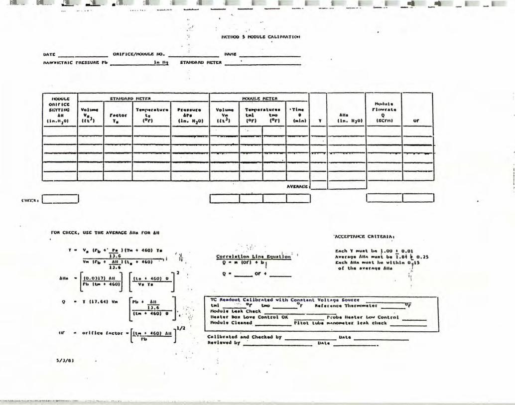
..• ·- -• --••· .a_ .. ..:L-- . t •. . ti ~- -~ _ ..
l"lll".(;K I
:-.-~ llr.fllOO ~ HUDUU: C/11.l"MTICIII
UATI: _____ Olllr1CC/t10CJUU: tlO. IWIB
Mnt111r.r1uc rncssunr. rb l.!!...!!:J. STNIDANJ NCTCII
ft()()UI,£ STMlt>l\110 IICTF.11 f100Ul, t: NCTCII
OR&rlCC t\\Mh•l• St:rTlltO Voll- T-r•ratvro P11:0 ■■11ro Vol- T•llf'•raturaa •Th•• rlowrala
All v. rector ... Ara ¥111 tiol t..., • Alla Q lln,11 101 cu.>, ,. c0rt Un. IIJDt cct>t c0 rt C0 rt liolnl ' 1 ln, IIJOt l&C:ntl ur ---
·-•11 ' -
c_
ro11 Cllf.CK, use TIU: AVCIUICC l\lla ro" All
' . v • crb • • ...!!. , ,,_ • 4'0) ,. ll , G I
"'" trb • ~• u.. • 4,o, · 1 U,6
I •f I~
Alla . [!•· .,.,, ·" 1 [1 ...... , ·r rb I..,_ • ◄(,OI v. ,.
Q .
ur
S/ l/llJ
Y 11 1 , 64) VIII
iT.i : ~- -. [~· "' ] , ... • 460) 9 ' , . • ··: -
i~•: l
orlflco factor •[1'-'" • 4G0t rb ]
l/2 All
,,.,.,...... I I I -IIVEIU\m:
"I\CCCl"Tl\ltCI: CIIITF;nll\1
:.{.·
Cornlatlon Lln• Eq11at~on ; 1
o • "' cori + b 1·
r.ach 1' IOU ■ t bn ~.OU t 0,0l A•er•9• 1111" Mv11t bo i.o-1 t n, JS r ... ch Alla •u11t h• vlthln O,i ll of tho avera,,a l\lla • J
.I • o • ___ or•
TC IIG ■clout. Callbrat.ed vlth Con11tanl Yolt 119a l&oul'ce t•l · ···· 0 r ""'° ____ 0 r lleferenco Th■l'-■ lOI' tlodula IAak Check 114atar 1to11 Lo•• co·11-t-,-o"'l--,O,...lt,--_~---=---- r cobo lleat■ r a.o.. Cont.-nl lttlclula Cleaned _______ rltot tut.a --t•r le•k check
. ,, I
Ur
C'allbrated and Chackod br ________ bale ________ _ lla¥1eved br _. _________ _
Pal.a

j
l
, i .. : .. j
TEST LOCATION FIRM
Rn Pbu A• Dn .. Time r .
~ ~ .
TII p·stk Tstk v:11 v, CO2 OJ. co
PARTICOtATC Tts·r DATA ( UP-H CV)
TIH! DAT! PROJECT NO.
.. PARAMETER
Run Humber Bacometric Pressure - in Hg Diameter inches or Stack Area - ft2 Nozzle Diameter - in. Total Sampling Time min. Calibration ·Factor Pitot Coefficient Avecage Square Root of Velocity Bead C in. B2-0) Avecage Ocifice Pressure Drop - in. B20 Average Hetec Temperature - •r Average Stack Pressure - in. B20 Average Stack Tempecature - •r Metec Volume at Heter Conditions - rtl Total Watec Vapoc Collected - ml I CO2 in Stack gas I 02 in Stack Gas I co in stack gas
~~ · ·. lfn · Total Particulate Catch - mg
-~ 1 . >::. ·.; -~ ,._ .. -· .;•-.-:-· . Pcess R/S to input· ultimate analysis
- _1 :. ~: ;:~."~·;.:, '. Enter 1. if. data ·not appllc_able .J -~·.: .. ::...;;.::,· · · ·; Enter P-Factor · if calculated
I ." • .::-• ..., • • .-. ..., _;..;.
·:.. \ ♦ : .. ~ .-••• , • • • j · .. _ .. ;·::-:.;•-~~<·•·.· ·. 1 J \ H \ Hydrogen in Fuel
, c · ··: . , carbon in Fuel '1 I S ., :. · :. \ Sulfur~ in Fuel ~ IN I Nitcogen in Fuel
] . . .. \ O · .· ::· \ oxygen in Fuel fl . ·}• --~- ' GCV : ·.·:•·:' Gross Calorific yoiWlle of Fuel
., l (BTO/lb)
i I
CALCULATED
Vm (STD) 'HzO "wd "ws v. A• o. 08 (STD) I I
Meter Volume at STD Conditions I H20 Vapor in Stack Gas Molecular Weight of Stack Gas Molecular Weight of Stack Gas Average Velocity of Stack Gas Stack Area (rt2)
(dry) · ( we_t) (PPH)
Actual Stack Gas Plowarate (ACFH) Stack"Gas Flowcate (DSCFH) \ Isokinesis
CONCENTRATION
· Particulate Concentration ( lb/DSCF) Pacticulate Concentration (gc/DSCP) Particulate Concentration (gc/ACF)
EHISSION RATES
2r Particulate Emission Rate (l~/hr)
rev . S/88
VALUe
.... . . --

?lant ?!.ant Locat i o:i •
Unit Tested ?roject No.
• Types of Samples
. I I Run I !>ate I C.:,nu.i::,.u I Oate of Time of I Location of
!iccb~r Sa.coled C.,de !)esc=i~tion 3.ecoverv Recoverv ?ecovery Si~ture Title
.
-
. -·.
. ..
. . . - -
I . I
~. I . .. .. -
~ I- ---- . -.
R!CIP!OOS OF SA..~U:S, other than recQverv ~erson(s):
Title Date & Ti=e
WORATOR'! P!:lSON(~) UC!IVINC SAM?t::S:
Signature Date & Ti=e

I:'-! • ·.;a ~•;i. . •' - - ""'fll - li1
l . , • .:.
L'... .____
~~"7. _-.. . . ix=-.. -- --- - -- - -l!rA Nl1100 9
ROCOM OP VISUAL ll.'TlllfUN/\TIOO 011 Ol'ACITT •I
- ._.!_ I ~ -- --- - - -
IDaS OP OIISl:RVATIOO ___________________ _ UH'Nn' -----------------Ull:ATIUi _________________________ ~~ --------------------------
TI~f MNllllll ________________________ OBSBM!R QlRTIPJCATION llr\TD __________________ _
' . ·)
llr\ll: ------------------------- .. . _ 0151:JM!ll AfflLIATIC'H ___________________ _ '· lYl'll l'ACll.llY ___ .. l'()JNf OP IHISSl<JtS _____________________ _
<:ux:ic TUil
Oll'ilillVJ:ll lJr.ATl<li
lll11Cance to Jhchlr1• Ill rrcl Ion Ira. clhch1r11 lkl l11ht "' OhHIVll lun l'ulul
filltl:K IIIIIUff
Wlll\lllllll U.tfUI TIU'6
Wlt11I IUrecl lun
Wind S11aeJ
Mlilenl TD!lllC:TllUre
llulatho t••lJhy • I
:;n Cltflll TICJIS (Clear. overcast, I cluuJ1, etc.)
rl.lHl OOSOl ll'TI 00
C.olur
llhlatKe Vlalble
1\1\C:t;t:IUNI ll~'itllll'flai
SlMWn' OF RJl~INGS
.
.. I . I I I .
111clty 0•Z0 I 21-30 I ll - 401 41-60 I 61·10 I 11 -100 I TCJTAL
No. of RcnJlncs I I I I . -f--t--11--+l ---f----•·--4-
l·re11uc11cy I
Rcadl11is over _I Averaae <>siaclty • _I llcaJln1s RanaeJ fro._ to_ I orachy, OW111cl ly cacccJoJ _I foa;- _.1n1_aec1. llo,culat lun:
0 l 1. 3 4 !:i
T 7
T 7f lo 11 Ii rr 14 15 lb rr IT l~ zo-zr
121 123 iZ4 25"' 26 TT 28 2n-
0 IS 30 .. .
--1---
' . -I -
-- --- -
4S -
----
-, I ---,_
-----
0 1S JO ll
30 45
Dl11r- o( Observer Locatlun - -IJl
IT" r,r ~~ - -~o - -J7 !If ,u- -;ro IT '1Z ~j - ,_
'14 ,_
'1S 4b ~,-- - --41f - --'19 Su rr rr IT 54
,_ ,_
S'S" - ,_
57," rr 5lf ~ - - -
1----
----'
-
-
Clh!lef'YOr. I
• I J
C.-nlS
SIJ11ahue _______ ... .. .•• .

l 1
~]
~J .]
]
1 "J
_ ]
-. J ,J
~fl ~J
?ARi l - ?RCSE c:Nr!G~P.Ai!ON
Probe Identiffca tion iechnfcal Spec1alfst
?1t~t Ident~fi cation ______ _
Ca ta
A.
a. ?robe
Joll tOt
r .
Pi tot
Nozzle
, -----
~r---d ---•---¾ C.(1) r------7=======::Qi t
Probe •
QB.
C I C.(2)) _____ _
_ Probe
J 1 f---i
r J
I
Spec1f1cat1ons (EPA Method 2) Dt • 3/16• to 3/8• On • 1/2"
I ?. J/4• b 2. 0
C.?. 3" d .?. 3" ~ i 3/4"' f i ,"
~
---
pl• Pb
ot -·----on ---a __ _
"a---Pb ---b __ _
c __ _
d __ _
e __ _
OR -C
f
1. a s o t !. P !: 1. :o o t
If these specifJcations are met, ~roce~~ w;th Part 2 ?1:,t alfgnment.
68

l 1 ·]
·.]
1 ]
l -l
]- .
']
··~ l
' ~) ~ l
I
-~ ] '1
'I : ] :J .
I .,, j
~J I J ,
,i ~,
,i
S-TY?! ?liOi GEOMEi~IC O..LI5AAT10N
?ART 2 • PliOT AL!Gi,M:.!-<i
·.-~ Probe tdenti fica t1on
Technical Specialist Date
Pitot tdentificat \on -------
A.
8.
Transverse Tube Axis
long 1 tud 1.na 1 • Tube ···. : Axis·
• a
b
C
d
e
9
a
b
C
d
e
8
a'
f o.
a.f + 'b1 • c1 ,ab • cos a
a1 + dl - e1 Zad • cos a'
{so0 < a < 100°j
{80~ < a' < 100°)
(g<l/3Z")
·, . NOTE: values in parentheses are 8'A Met~od 2 specifications.
. PROSE. IBEAAOCOUPLE CAlloAAilOH
Expected Stack Tempe.ratun {is>
Mercury Thermometer {Tref)
Thermocouple Readout
Probe Identification Technician
iol erancu OR -----
_____ 0R - (T5
:, 10:)
_____ o~ (Tref !. 1.5!)
Date
69
g_

, NOZZ:.~ o.!.!EAAT!CN DATA
·1 Nc%:tle Set No. Cate Tech.
•J
:I Nozzle No. Diameter• - a. b - C ave::-age••
l . ·1 -----7------...--1-------- -------•·-
I -------=,- --------+------+-----~ _____ _, _______ ....
. . I i~ l --I ~l ~-, 1 ~ .c 1 •
j
i I
! J
•::ieasure to nearest • 001 •
! j **th.ree measurements must~ vi~~:..~ .004• of each o~her
.j I ~
I
' .I ' '!
70

l
]
1
l ]
·-·------ .. --- . . .. .. . - .....
cu.t.: ~ca,-~ oc::x. l'IOUC-~" •• U 11t:::x: ;r:-J1t:1u.-:::ar. uo AJCA.:.tSIS vA:..::>.-:::uc
r:J:11 -----------------------~: 11".:KIU ----------------------
.1.n C~l: 1na!y111 of :.Oller t&fta11•t fllll 11 con1i41te4 ••l!4 lf t~• r0 caleulat-4 !roe
-t~e 0~1: &Nlflll 11 •ltft l n :s, of Ue 'o ca1C\11at.t t:oe t11el an&ly1l1. lf !11•1 an.&!7111 dat& 11 aoc. •••1!ao1e, the r 0 calc:vlat-4 !:o•
SAJ\l~!MC ~::ox ___________________ _ u,. OUA': u1::.71U •111t H Ylt!lla Z 51 of Ut aterat• puoU,e" r0 !or • tltell !Ml u :oUowu
SMIU PIOlS~ c::itt:%>tT ________________ _
' l-'ISID"f ':t1'!1UA~ ------------------
~~ ---------------------
.l.nUtK!t ■
11,-1no.i1 ·-t.ltalt ■
011 .. ,oral CAI Propal\e 1111.ue 'IICo4 a.ra
o~.i.-:- cno, ,u-~-:- uu cn:::x, .x!.::.A:. •1 o aln.
1vi. r 0
1.010 .... 1.140
1.07' 1.l4' 1.,u 1.no 1.'1, 1.0s0 1.0$5
1.ou - 1.: .. 2' 1.ou - 1.1n 1.022 • 1.!JI 1.2n • 1.,11 1.u2 - 1.u, 1.u, - 1.su 1.,u - 1.su o.u,s- 1.::.02 1.ocJ - 1.:.0,
M::::O"":.u«:% t.:X.."":'1 t%U < O. 2 i!i's u a. --;rlUJ. s1 S sin. ,,z-nu umnxr 0z • _,, ~~ 1.!X::-s or ez • 2~ 21 •• ,
I 110t-e ;~.-.1 vr.c:r. ~v.::cw
~~1011 :0 ~
I~ 1 I 2 'J 11:)r.zc:"'..U vr.c:r. or
e,2
02
~
•2
II • "• •
~"" I ~ . ~ lvn..t.a •· ,c::,:::n.:a
U.\DI)'(; ' J.Ul)t)IQ \ s.u.=niii. ' ' 1 ■ 11 .
1•11 fall
I I I I I I .
I I I U/100
, . I I I I I I lUlOO I I I
I I I I I 1 · I :ar.oo I . I
I I I I I ,. I ! :1r.oo I
. 1100 • \ 1,01 • 11 n ·1
2D1 "• • r:11.:i • 100 •
1"0& !'•lM:':'Oa w.c::r..1T:0KS At.:. 0~-:- .uo,:.:rn:s KOS': It .1tC11 ~ :-1:r.:::,.~ AC tc:rn AQU wt:-a Uoa c.-:n1 ':'Cl wr..I• O.l, It ?0"..::XZ
o~u cnrr, POr.•:UT ~ c:ucr, ~J.l. al a stn. J.C:::Z::r...UCZ t.~1 tD.E C 0.2 .Iisi1" 0 --;T"~ s1 S sin. P'Or.•':':ff 1111 IDr. Oz • _, f ~ t.!l\::-1 ""'ciioz • 'io.r- 21. :,
Fuel lndyat, r0
• 20.t fl.SJ 1C •!.,,\I• O.S1 \I• 0. 1• \K • o. •I ,c, O.lU IC: (1001 •
~c.A.S Ku
1 !I /l :.-.o lt
-
20.,--' 01 • 'c::,z
_______ , t.e::1punc:1 t.!a!u au •~ •DO"••
•u1u.■ la1 ~ conceaun1o• ll 11 .. lU1l• r< ::ca ;,peJ
.

APPENDIX 2
TABLE OF OPERATIONAL PARAMETERS
,,
I
!! l:l
\
72

~
...J ., w
r&..,., .!,_. .!...,_.,, .... ' .
OPERATING PARANETER
Exlt. Gas tmp (°F
Shale Feed Rat.e
Carbon Honodde CO (PPH)
Oxygen Oz (")
J..Gi' PIO\I (Gl'N)
Combwl t. l on Gas Velocity (ID Pan
NIPS)
Atomizing Alr PreHure (PSIG)
Ll- Feed Rate
Scrubber/Vent.url Wat.er FlO\I (GPH)
Scrubber Pressure Dr op
Kiln Pressure
PROCESS HONITOR (INSTRUHENT)
thermoc:ouple
Load cell
Non-dlaperalve Intra-Red Source & Opt.lcal Detect.or
Paraaaasnet.h:
Ha•• Flowneter
A1111iet.er
Gauge
Sol lds Peeder
Parahal l Plu.
DI tterent.lal Pr eaaure Gauge
Phot.ohel le Dltterent.lal Gaus•
LOCATION
Rear Kl ln Hood
Feed COC'IY9yor
Bxhauat. Gas Staci!.
£xhaW1t. Gaa Staci!.
Kl In Control Roaa
ID Pan Hot.or Current. Read-out. Kiln Control Roaa
Kiln Control Roaa
At. Ll- Feeder
At. Dl11charse to Sett.Ung Pond
At. Scrubber
Klln Front. Hood
™ll..U (!' U,!RATJ(!!AI. P/JWtlm'S5
OPERATING RANGE
850°F-95o°F
15-20 t./h
· Aut.anat.lc 0-100 PPM 0-300 PPN 0-1000 PPN 0- 3000 PPH
Aut.omat.lc o-1ox 0-15" 0-25"
0-10 GPH
350-390 NIPS
60-70 PSIG
180-200 GPH
4-6• HzO
-. 10 to - . 05
~ SET POINT(S)
880°F (LO)
22 t./hr
100 PPH -
""-LOW 18"-Hl
8
400 NIPS
50 PSlG
180 GPK
2• HzO
HzO -0 . 05
CllT--<>FF SET POINT(S)
850°F
-*100 ppm tor
10 •lnutea
*10 Gl'N
419* (D~r set at. OX)
40
2, 9 lb~ per lb Cl
175 GPH
1, 5• HzO
>-0 . 05• tor 15 sec.
C01111Eln'S/SI lllTDO\IN Tl HE INTERVALS
Shut. LGP tlO\I •"l t.ch t.o alternate fuel aft.er 20 mlnut.es ot t.~rat.ure belO\I cut.-oU l lmlt.
•lnt.erlm Operat.lonal ahut.-ott valve. Plna l llml t.a LO be deter■lned ckJr lns t.rlal burn. Ceaaat.lon ot I.GP tlO\I \llll be \llt.hln 10 ■ln. after exceedance ot tlnal llml t..
•IO tan IIIJl>er•se "Ill be uaed •• a surrogate ot coni>ust.lon sa• velocity. Operational -xlnun value to be determined ck.&rlng trial burn. Cut.oft ot LGP flO\I \llll occur aft.er 20 mln. ot exceeding operat.lonal llmlt.s.
PIO\I tor each 1.¥11 t. . Swl tch to bacil.-up ~/no automatic cut.- oU since that \lould caW1e scrubber -lt down . lnrnedlate shut-ott atter 10 min. tw>lnu n..it-o!t val"•
Halnt.aln negat.lve pressure \llt.h ki ln/ at.t.eq>t. to correct. pr-obi- t.o achieve negative at.ate; lt not corrected \llt.hln 20 mln. ahut.-ott ·
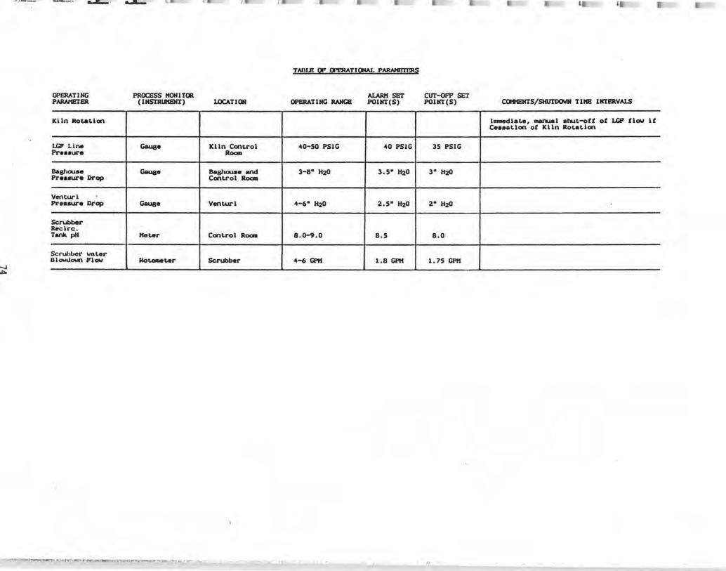
-.J
""'
-•~..umr- ..,..._ .. ........
OPERATING PAIWIEJ'ER
Kl 1n Rot.atlan
I.GP Line Pre■■ure
Baghouae Preaaure Drop
Venturi • Pl'eHua-e Drop
Scrubber Reclrc. Tank. pH
Scrubber wnter Dlowuown Plaw
....._
PROCESS ltONITOR ( lNSTRll'IENT)
Gaus•
Gaus•
Gauge
Meter
Mo'--l.er
LOCATION
Kl ln Control Room
Baghouae and Control Room
Ventua-l
Control Room
Scl'Ubber
- I
I'.
TAnlB OP trl!RATJON,\L p~
OPERATING RANGE
-40-50 PSIG
3-8• H20
-4-6• H20
8.0-9.0
-4-6 GPH
AURM SET POlNT(S)
-40 PSlG
3,5• H20
2,5• H20
8.5
1.8 GPH
CUT-<>F'P SET POlNT(S)
35 PSlG
3• H20
2• H20
8.0
1,75 GPH
.,.;:
C011HENTS/SHUTDOWN Tll1B INTERVALS
1..-dlate, --..al atut-ott of LGP flow U Ceaaatlon of Klln Rotation

J J
:J
~J :1 J
lll
J· ,.
APPENDIX 3
TABLE OF PROCESS MONITORING EQUIPMENT
75

---- ......... I t::
FUNCTION HANUPACTURER HODEL
I.GP Plow Klcro-ttot.lon El-t -175-100-S-128
Pl-T~ lrcon 0-45P05-0-0 1-53-0/000
Katerlal (Stone) Jrcon R-25POS-o-o-T~ )
1-53-0/000
Eait Gaar~: Omega Engineering
T)ll>e J
C.rbon Nonoxide Sll-1■ Ultr-t (CO) SB
Oxygen Slemena O~t SH (02)
.-t1 -'lil1..(..•• • I
TADLB OP PROCllSS t«:»fl!WING Egulrt®n'
O~TING PRJNCIPLB
KaH Plowneter
Flame ~ter-0.l Klcron centered at 4.S alcrona
Two-color pyrometer 0.7 to 1 . 05 microns narrow bend centered at 1.05 ■icrons
Thermocouple ( l ron/Cona tant.lln)
non-dlapor■ lve Infra-red llrct source & opt cal detector, double beam
P■ramasnetlc
,. •.~·.-..,T. '1
OPERATING (RANGS(S)
0-20 1JP11 Pull Scale
1500°1'-4500°1'
1300°1'-25000p
320p-13a20p
automatic 0-100 l'PK 0-500 PPK 0-1000 PPH 0-3000 PPH
automatic 0-1°" 0-15" 0-25" 0-50"
R.ESPONSB TlHB
0.1 ■ec:.
1.0 aec.
0.1 aec.
~rox. •ec.
Le■■ than 3 aec. to 90" of Clnal value
5 ■ec.
ACCURACY'
+0.4" of ?low rote
vithln 1.°" of full scole t~ or 10°F which-ever I• greater
vi thin 1. o" ot full ~ale tea,p of 10 , which-every ls greater
+40p or +O. 75" wichevcr 1 ■ sreater
!3" of full ■calo
•2" ot mea■ured value at c;el l out.put
CALIBRATION HETHODS/FRE,QUENCY
factory detenalned
Internal cal I-br■tlon checll circuit- factory aet
Factory aet-Internal cal I-bratlon check circuit
Standardization perCorlllOd by mlc;roproceaaor u■ lng self-con-talned, lnt.ernal standards
02 Cal lbratlon gas-certified ■Ix 02 ln N2 free of conbustlbles/ a,lcroproceasor technoloSY for ay■ te111 calibration
•
CCMEITS
R~atllblllty - vlthln 0. X of full acale teq>
R~atablllty - vlthln O. X of ful I acale tea,p
Repeatability - ! 2" of Cull ■cale
Repeatability - !0.2" of measured value

- t..ATu-... llo\f.;tN ~ -1' ~:~ I ~~ ,,
PUNCTION KANUPACTURER tt0DEL
CaNlU&tlon s•• ~ - Bal"l"0Cl -velocity {10 fan Sy■tema Fng aq,er-aae) ~ t!llllC -
• i::.
~ Atanizlng Alr OJlnc:y OSI-Ser-le■ pr-e■■ure Coq>r-e■■or Hodel 490
(100 H.P.)
Gause \lek■ ler-Inatr-~t 05-023-105
Water- flow P l ■her--Porter- ~ 10P1940 thl"oat
Scr-ul>ber- water- Dwyer- 02015 pr-oaaUl"e dl"q>
Combu■tlon Air-- Pr-hnar-y (FOl"ced dl"aft
fon)
Ket.er G.E. 64761C51065
- Secondary (POl"ced draft fan) G;E,
Kl In Pl"e■aw-e Dwyer-
(~·,·,:,1
TABLB w "8'D"S5 tl()NITORING EWll'IDfl' (K-1)
OPERATING PRINCIPLE
Induced dl"aft
Cur-rent tran■ foraar-
Hel lcal ■Cl"ev 011 flooded, Single at.age
-Pan■hall Pli.m.
Kagnehellc Gauge
-
-
Photohellc Gauge
OPERATING {RANGB{S)
-0-500 aq>a
0-125 p■ lg
0-100 p■ lg
0.01 to 0.30 HOO
0-15• 1120
0-150 aapa
0-100 aap■
-0.5• to+ o.s• H:z(I
RESPONSE TIME
-
-
--
-
-
-
-
ACCURACY
-+ 1" of
fuTl scale
-
--
! 2X
+ 1" of ?ull ·scale
+ l" of ?ull scale
.: 2"
••
CALIBRATION METHODS/FREQUENCY'
-
-
--
-
-
-
■!._
COl'tt1ENTS
-lndlcatlng -tel"
-
-
-
-
-