trenchless construction feasibility analysisfiles.dep.state.pa.us/programintegration/pa pipeline...
TRANSCRIPT

Trenchless Construction Feasibility
Analysis
Pennsylvania Pipeline Project
Prepared for: Sunoco Pipeline, L.P. 535 Friztown Road Sinking Spring, PA 19608 Prepared by: Tetra Tech, Inc. 661 Anderson Drive Pittsburgh, Pennsylvania 15220 (412) 921-7090 Fax (412) 921-4040 December 2016
Trenchless Construction Feasibility Analysis Page ii
TABLE OF CONTENTS Section Page
1.0 GROUNDWATER PROTECTION PLANS ...................................................................... 1
2.0 TRENCHLESS FEASIBILITY ANALYSIS ....................................................................... 1
2.1 CONVENTIONAL AUGER BORING ................................................................... 1
2.2 HORIZONTAL DIRECTIONAL DRILLING ........................................................... 1
3.0 PROCESS OVERVIEWS ............................................................................................... 2
3.1 CONVENTIONAL AUGER BORING PROCESS ................................................. 2
3.1.1 Site Arrangement ..................................................................................... 2
3.1.2 CAB Process Step #1 – Entry Pit Excavation and Preparation ................. 3
3.1.3 CAB Process Step #2 – Horizontal Boring ................................................ 3
3.1.4 CAB Process Step #3 – Completion of Boring .......................................... 4
3.2 HORIZONTAL DIRECTIONAL DRILLING PROCESS......................................... 4
3.2.1 Site Arrangement ..................................................................................... 4
3.2.2 HDD Process Step #1 – Drilling the Pilot Hole .......................................... 5
3.2.3 HDD Process Step #2 – Reaming of the Pilot Hole .................................. 6
3.2.4 HDD Process #3 – Pipe Preparation and Pullback of the Pipeline String .. 6
3.2.5 HDD Drilling Fluids ................................................................................... 7
4.0 FEASIBILITY ANALYSIS CRITERIA .............................................................................. 8
4.1 CONVENTIONAL AUGER BORING ................................................................... 8
4.1.1 Physical / Technical Constraints ............................................................... 8
4.1.2 Practicability Constraints .......................................................................... 8
4.1.3 Geological Constraints ............................................................................. 9
4.2 HORIZONTAL DIRECTIONAL DRILLING ........................................................... 9
4.2.1 Physical / Technical Constraints ............................................................... 9
4.2.2 Practicability Constraints ........................................................................ 10
4.2.3 Geological Constraints ........................................................................... 12
5.0 TECHNICAL FEASIBILITY ANALYSIS ..........................................................................13
5.1 WETLAND-SPECIFIC TRENCHLESS FEASIBILITY ANALYSIS .......................13
5.2 STREAM-SPECIFIC TRENCHLESS FEASIBILITY ANALYSIS .........................14
5.3 TRENCHLESS FEASIBILITY ANALYSIS MATRIX ............................................15
5.4 SUMMARY OF TRENCHLESS FEASIBILITY ANALYSIS RESULTS ................16
List of Figures Page
Figure 1: Typical CAB Entry Pit Workspace Area – Diagram .................................................... 2 Figure 2: Typical CAB Entry Pit Workspace Area – Photo ........................................................ 3 Figure 3: Typical HDD Entry Workspace Area .......................................................................... 4 Figure 4: Typical HDD Exit Workspace Area ............................................................................ 5 Figure 5: Drilling the Pilot Hole ................................................................................................. 5 Figure 6: Reaming of the Pilot Hole .......................................................................................... 6 Figure 7: Pullback of the Pipeline String ................................................................................... 6

Trenchless Construction Feasibility Analysis Page iii
List of Tables Page
Table 1: Typical HDD Entry and Exit Workspace Areas ........................................................... 5
Table 2: HDD Maximum Installation Lengths ......................................................................... 11
Table 3: HDD Geological Feasibility Analysis Criteria ............................................................ 13
Table 4: Trenchless Construction Feasibility Analysis Matrix ................................................. 18

Trenchless Construction Feasibility Analysis Page 1
TRENCHLESS CONSTRUCTION FEASIBILITY ANALYSIS FOR PENNSYLVANIA PIPELINE PROJECT
1.0 GROUNDWATER PROTECTION PLANS
Sunoco Pipeline L.P. (SPLP) has developed four plans that accompany the Erosion and Sedimentation Plan (E&S Plan) that are designed to assess the potential impacts and provide for the protection of groundwater from contamination due to project activities. The overarching Prevention, Preparedness, and Contingency Plan (PPC Plan) is designed to address spill prevention in general, and potential impacts to surface waters and public and private water supplies in particular have been analyzed and addressed within two supplemental plans to the PPC Plan; the Water Supply Assessment, Prevention, Preparedness, and Contingency Plan (Water Supply Plan) and the Inadvertent Return Assessment, Prevention, Preparedness, and Contingency Plan (IR Plan). The Water Supply Plan provides for the assessment of the existing environment in terms of public and private water supplies in or along the project areas and impacted waters, as well as the prevention and preparedness measures to be implemented to protect those supplies. The IR Plan outlines the preconstruction activities implemented to ensure sound geological features are included in the HDD profile, the measures to prevent impact, and the preparedness plan if an impact were to occur. In addition, a Void Mitigation Plan for Karst Terrain and Underground Mining is provided as part of the E&S Plan and provides an assessment of potential impacts and avoidance and mitigation measures during open‐cut and drilling procedures. The purpose of these plans is to protect groundwater resources project‐wide.
2.0 TRENCHLESS FEASIBILITY ANALYSIS
Provided herein is a trenchless construction technology feasibility analysis for steel pipelines associated with the Pennsylvania Pipeline Project. Specifically, the construction methodologies analyzed are conventional boring and horizontal directional drilling. The intent is to compare these methodologies to each other, as well as to conventional trenched pipeline construction techniques.
2.1 CONVENTIONAL AUGER BORING
Conventional auger boring (CAB) or jack and bore is a dry trenchless method of installing a relatively shallow underground steel pipe, from an excavated entry pit to an excavated exit pit, beneath an avoidance obstacle. Specifically, a specialized track machine pushes the product pipe into and through the ground, while simultaneous auger boring to remove the spoil from within the pipe. This push and clean-out process is repeated for each pipe segment until the desired total installation length is achieved. The technique has been utilized extensively in the United States for numerous decades, primarily for pipelines constructed underneath road and railroad crossings. A representative animation of the CAB process is available at the following link: http://www.allenwatson.com/auger-boring.html Notwithstanding the description of CAB, this construction method cannot be implemented in every location. There are various physical / technical, practical, and/or geotechnical constraints which can limit or completely eliminate the feasible use of CAB in particular locations.
2.2 HORIZONTAL DIRECTIONAL DRILLING
Horizontal directional drilling (HDD) is a steerable trenchless method of installing underground pipe, conduit, or cable in a shallow arc along a prescribed bore path by using a surface-launched drilling rig, with minimal to no surface impact along the bore path. The easiest forms of HDD emerged in the 1960s and have since been advanced and typically
Trenchless Construction Feasibility Analysis Page 2
utilized when conventional trenching techniques are not desirable or practicable. It is suitable for a variety of soil conditions and primarily intended for obstacle avoidance including, but not limited to, river crossings, roads, and environmental features. A representative animation of the HDD process is available at the following link: https://www.youtube.com/watch?v=CkdOwJc_eR8 Notwithstanding the description of HDD, the application of HDD is not suitable in every location. There are various physical / technical, practical, and/or geotechnical constraints which can limit or completely eliminate the feasible use of HDD in particular situations.
3.0 PROCESS OVERVIEWS
3.1 CONVENTIONAL AUGER BORING PROCESS
3.1.1 SITE ARRANGEMENT
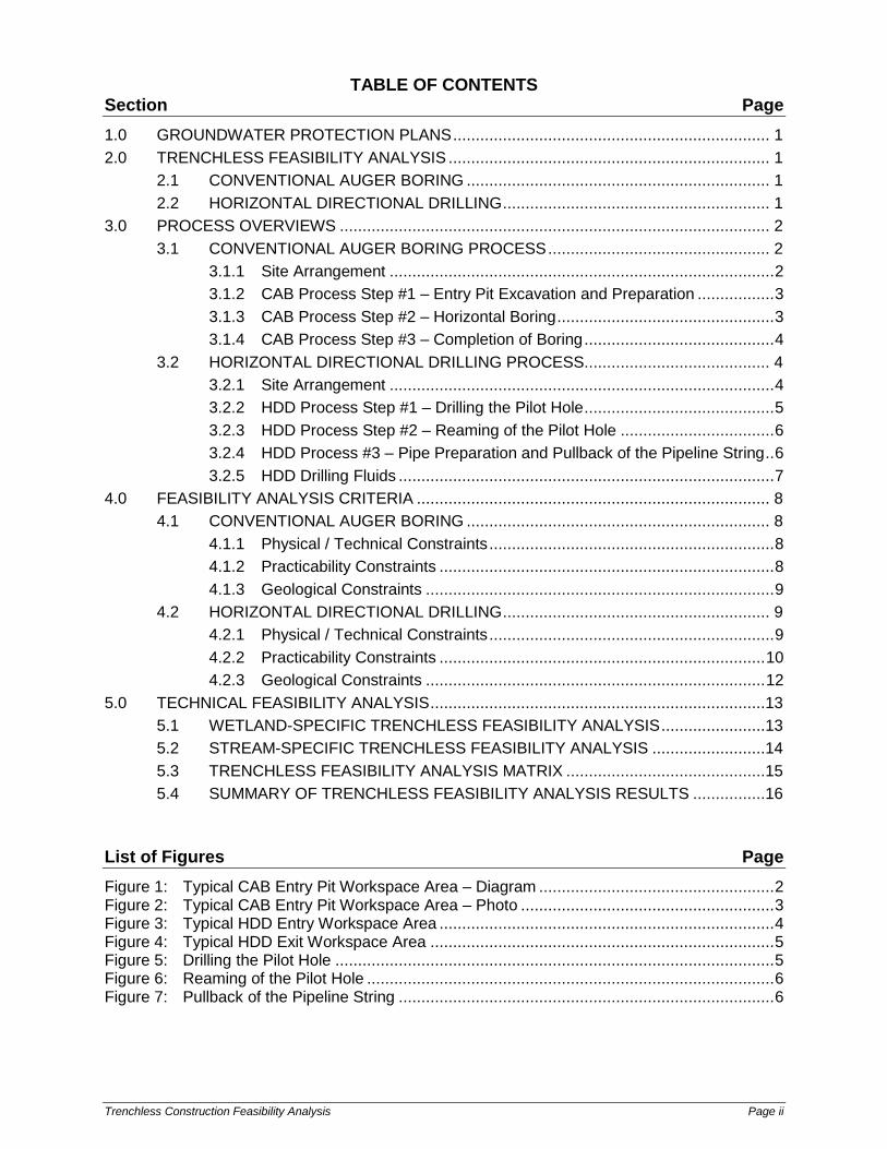
The CAB construction site is divided into three primary sections along a linear path as follows: o Entry / working pit workspace o Obstacle to be avoided o Exit / receiver pit workspace The entry pit workspace is generally 30 to 40 feet in length, 10 to 12 feet in width, and generally 10 to 15 feet in depth, but depth may vary depending upon site-specific topography. The entry pit workspace typically contains the following features (see Figures 1 and 2): o Machine track ○ Boring machine o Sheet pile pit backing plate ○ Pipe casings & auger sections o Cutting head(s) & auger sections ○ Spoil collection tray
Figure 1: Typical CAB Entry Pit Workspace Area – Diagram

Trenchless Construction Feasibility Analysis Page 3
Figure 2: Typical CAB Entry Pit Workspace Area – Photo The contents and size of the exit pit vary with the complexity of the site specific boring. Exit pit sizes range from as large as entry pits to no pit at all.
3.1.2 CAB PROCESS STEP #1 – ENTRY PIT EXCAVATION AND PREPARATION
The first step in the CAB process is the reaming of the pilot hole. This process is summarized below: o Excavation pit boundaries and boring alignment are surveyed according to the detailed
engineering design. o Excavations are implemented pursuant to requisite Occupational Safety and Health
Administration (OSHA) shoring and/or sloping regulations. o The most critical part of the bore is the setting of the machine track on line and grade.
Proper foundation support typically requires crushed stone and may include poured concrete.
o A backing plate, consisting of steel pilings, steel plate, concrete barrier, and/or wooden timbers, is normally installed along the back of the boring pit. This supports the thrust of the boring machine as the product pipe is advanced into the ground.
o The boring machine is placed upon the track. o Pre-assembled casing pipe and imbedded auger is lowered into the pit, aligned on the
track, and secured to the boring machine. In most cases, the leading casing has a slightly larger diameter band welded to the front, which compacts the soil and relieves pressure on the remaining casing by decreasing skin friction.
3.1.3 CAB PROCESS STEP #2 – HORIZONTAL BORING
The second step in the CAB process is horizontal boring under the avoidance obstacle. This process is summarized below: o The bore is begun by carefully thrusting the casing pipe into the ground along the
correct line and grade. Simultaneously, the auger inside the casing is rotated by the boring machine to clear the progressing casing and pull the spoiling into the entry pit for removal.
o After the first section has been installed and checked for accuracy, the boring machine is disconnected from the casing pipe and auger and slid to the rear of the bore pit.
o The second casing / auger section is lowered into position. The auger ends are connected to the boring machine and tail end of the first auger section. The leading end of the casing pipe is welded to the tail end of the first casing pipe section.
Trenchless Construction Feasibility Analysis Page 4
o This process of casing / auger section installation, thrusting, boring, and clean-out is repeated until the desired total installation length is obtained.
3.1.4 CAB PROCESS STEP #3 – COMPLETION OF BORING
The final step in the CAB process is the completion of the boring. This process is summarized below: o The boring machine is shut down and the cutting head is removed from the exit pit. o The boring machine is re-activated and operated in the normal direction for final
cleaning. o The boring machine is pulled to the rear of the bore pit to expose a section of auger
stem. The auger stem is removed and the bore machine pulled forward and connected to the remaining auger stem(s).
o This process of auger stem removal is repeated until the casing pipe is empty. o The equipment in the entry and exit pits is removed in the reverse order to which it
was installed. o The workspace areas are restored pursuant to project specifications.
3.2 HORIZONTAL DIRECTIONAL DRILLING PROCESS
3.2.1 SITE ARRANGEMENT
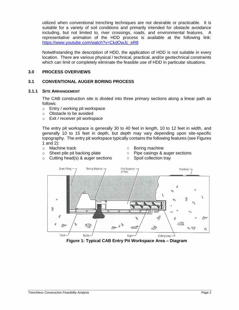
The HDD construction site is divided into three primary sections along a linear path as follows: o Drill entry workspace o Obstacle to be avoided o Drill exit workspace The drill entry workspace typically contains the following features (see Figure 3): o Drill rig & HDD entry point ○ Power unit & control trailer o Mud pump ○ Fluid system & tank o Drill pipe ○ Other supporting equipment & supplies
Figure 3: Typical HDD Entry Workspace Area
Trenchless Construction Feasibility Analysis Page 5
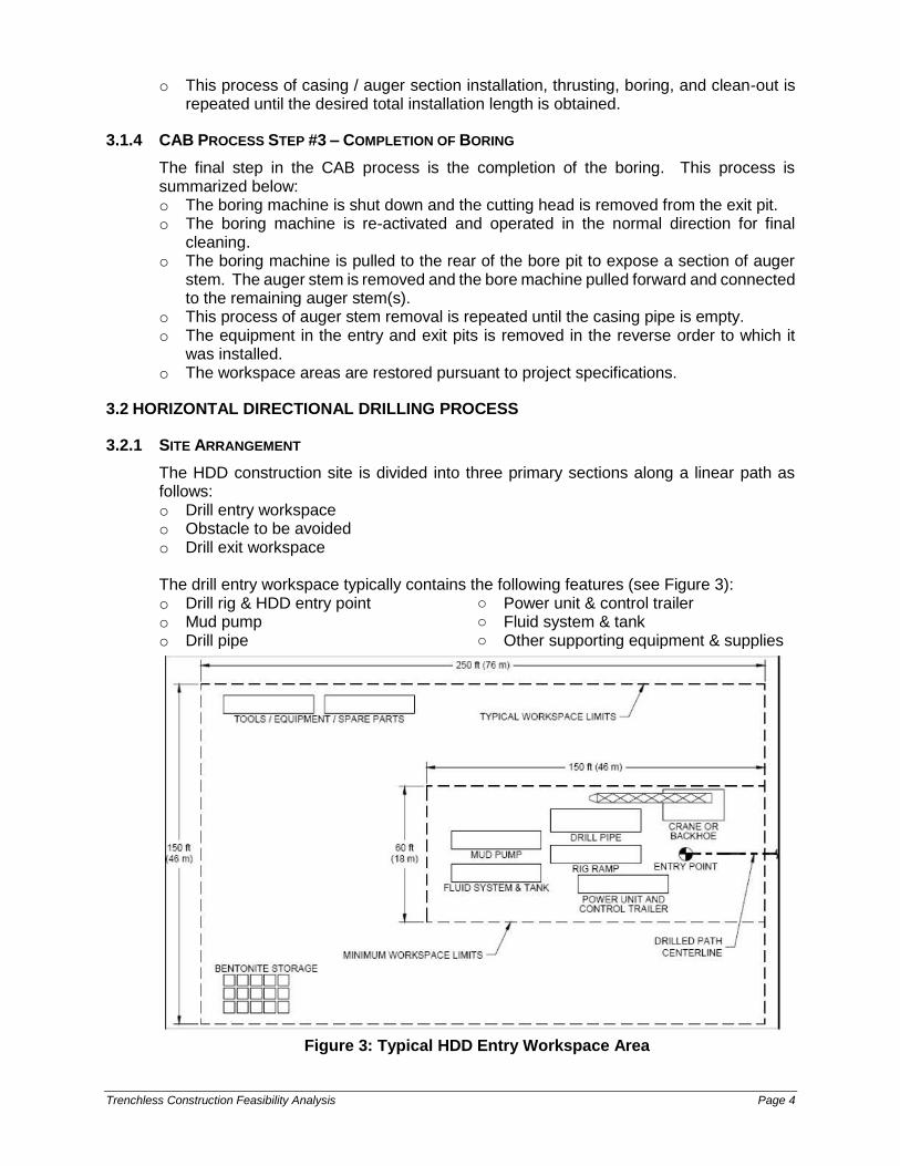
The drill exit workspace typically contains the following features (see Figure 4): o Exit point ○ Prefabricated pullback pipeline section o Pipe handling equipment ○ Other supporting equipment & supplies
Figure 4: Typical HDD Exit Workspace Area The size of the entry and exit workspace areas is directly related to the diameter of the pipe to be installed. A summary of typical workspace areas is provided in Table 1 below:
Table 1: Typical HDD Entry and Exit Workspace Areas
System Description Entry Workspace Exit Workspace
Maxi-HDD (24” to 48” diameter pipe) 150’ x 350’ 150’ x 250’
Midi-HDD (12” to <24” diameter pipe) 150’ x 250’ 100’ x 200’
Mini-HDD (2” to <12” diameter pipe) Varies greatly per site Varies greatly per site
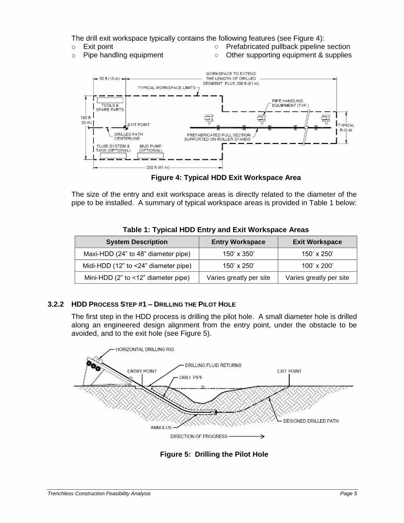
3.2.2 HDD PROCESS STEP #1 – DRILLING THE PILOT HOLE
The first step in the HDD process is drilling the pilot hole. A small diameter hole is drilled along an engineered design alignment from the entry point, under the obstacle to be avoided, and to the exit hole (see Figure 5).
Figure 5: Drilling the Pilot Hole
Trenchless Construction Feasibility Analysis Page 6
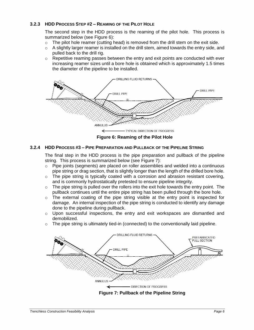
3.2.3 HDD PROCESS STEP #2 – REAMING OF THE PILOT HOLE
The second step in the HDD process is the reaming of the pilot hole. This process is summarized below (see Figure 6): o The pilot hole reamer (cutting head) is removed from the drill stem on the exit side. o A slightly larger reamer is installed on the drill stem, aimed towards the entry side, and
pulled back to the drill rig. o Repetitive reaming passes between the entry and exit points are conducted with ever
increasing reamer sizes until a bore hole is obtained which is approximately 1.5 times the diameter of the pipeline to be installed.
Figure 6: Reaming of the Pilot Hole
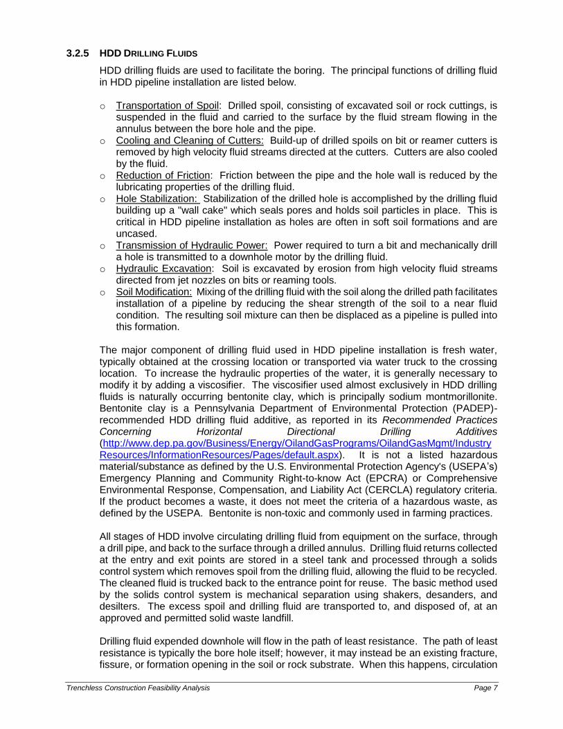
3.2.4 HDD PROCESS #3 – PIPE PREPARATION AND PULLBACK OF THE PIPELINE STRING
The final step in the HDD process is the pipe preparation and pullback of the pipeline string. This process is summarized below (see Figure 7): o Pipe joints (segments) are placed on roller assemblies and welded into a continuous
pipe string or drag section, that is slightly longer than the length of the drilled bore hole. o The pipe string is typically coated with a corrosion and abrasion resistant covering,
and is commonly hydrostatically pretested to ensure pipeline integrity. o The pipe string is pulled over the rollers into the exit hole towards the entry point. The
pullback continues until the entire pipe string has been pulled through the bore hole. o The external coating of the pipe string visible at the entry point is inspected for
damage. An internal inspection of the pipe string is conducted to identify any damage done to the pipeline during pullback.
o Upon successful inspections, the entry and exit workspaces are dismantled and demobilized.
o The pipe string is ultimately tied-in (connected) to the conventionally laid pipeline.
Figure 7: Pullback of the Pipeline String
Trenchless Construction Feasibility Analysis Page 7
3.2.5 HDD DRILLING FLUIDS
HDD drilling fluids are used to facilitate the boring. The principal functions of drilling fluid in HDD pipeline installation are listed below.
o Transportation of Spoil: Drilled spoil, consisting of excavated soil or rock cuttings, is
suspended in the fluid and carried to the surface by the fluid stream flowing in the annulus between the bore hole and the pipe.
o Cooling and Cleaning of Cutters: Build-up of drilled spoils on bit or reamer cutters is removed by high velocity fluid streams directed at the cutters. Cutters are also cooled by the fluid.
o Reduction of Friction: Friction between the pipe and the hole wall is reduced by the lubricating properties of the drilling fluid.
o Hole Stabilization: Stabilization of the drilled hole is accomplished by the drilling fluid building up a "wall cake" which seals pores and holds soil particles in place. This is critical in HDD pipeline installation as holes are often in soft soil formations and are uncased.
o Transmission of Hydraulic Power: Power required to turn a bit and mechanically drill a hole is transmitted to a downhole motor by the drilling fluid.
o Hydraulic Excavation: Soil is excavated by erosion from high velocity fluid streams directed from jet nozzles on bits or reaming tools.
o Soil Modification: Mixing of the drilling fluid with the soil along the drilled path facilitates installation of a pipeline by reducing the shear strength of the soil to a near fluid condition. The resulting soil mixture can then be displaced as a pipeline is pulled into this formation.
The major component of drilling fluid used in HDD pipeline installation is fresh water, typically obtained at the crossing location or transported via water truck to the crossing location. To increase the hydraulic properties of the water, it is generally necessary to modify it by adding a viscosifier. The viscosifier used almost exclusively in HDD drilling fluids is naturally occurring bentonite clay, which is principally sodium montmorillonite. Bentonite clay is a Pennsylvania Department of Environmental Protection (PADEP)-recommended HDD drilling fluid additive, as reported in its Recommended Practices Concerning Horizontal Directional Drilling Additives (http://www.dep.pa.gov/Business/Energy/OilandGasPrograms/OilandGasMgmt/IndustryResources/InformationResources/Pages/default.aspx). It is not a listed hazardous material/substance as defined by the U.S. Environmental Protection Agency's (USEPA’s) Emergency Planning and Community Right-to-know Act (EPCRA) or Comprehensive Environmental Response, Compensation, and Liability Act (CERCLA) regulatory criteria. If the product becomes a waste, it does not meet the criteria of a hazardous waste, as defined by the USEPA. Bentonite is non-toxic and commonly used in farming practices. All stages of HDD involve circulating drilling fluid from equipment on the surface, through a drill pipe, and back to the surface through a drilled annulus. Drilling fluid returns collected at the entry and exit points are stored in a steel tank and processed through a solids control system which removes spoil from the drilling fluid, allowing the fluid to be recycled. The cleaned fluid is trucked back to the entrance point for reuse. The basic method used by the solids control system is mechanical separation using shakers, desanders, and desilters. The excess spoil and drilling fluid are transported to, and disposed of, at an approved and permitted solid waste landfill. Drilling fluid expended downhole will flow in the path of least resistance. The path of least resistance is typically the bore hole itself; however, it may instead be an existing fracture, fissure, or formation opening in the soil or rock substrate. When this happens, circulation
Trenchless Construction Feasibility Analysis Page 8
can be lost or reduced. This is a common occurrence in the HDD process, but does not prevent completion. However, the HDD process has an inherent risk of inadvertent return of drilling fluid to the surface at a location in an upland area, on a waterway’s banks, or within a waterway or wetland. Although non-toxic, an inadvertent return has the potential to physically impact plants and fish if discharged to waterways in significant quantities.
4.0 FEASIBILITY ANALYSIS CRITERIA
The intent of this section is to provide a comparative assessment of the trenchless excavation methods CAB and HDD for steel pipelines. The following assessments will detail the physical / technical, practicability, and geological constraints.
4.1 CONVENTIONAL AUGER BORING
4.1.1 PHYSICAL / TECHNICAL CONSTRAINTS
Pipe Diameter CAB can be utilized with welded steel pipe from 4” diameter to at least 60” diameter, with the most common diameters ranging from 8” to 36”. Accordingly, CAB is a potentially feasible trenchless crossing method for the Project-proposed 16” and 20” pipelines based on existing technology. Bore Pit Depth CAB pit depths, and thus the product pipe installation depths, are a function of the avoidance obstacle constraints and the practicable depth at which operators can work safely. Comparatively, these depths are much less than those obtained by HDD. Site Topography Site-specific topographic conditions have a substantial bearing on the potential feasibility of conducting a successful CAB. A CAB fundamentally involves horizontal boring and straight alignment to install a pipe beneath the obstacle to be crossed. Accordingly, a CAB construction area requires not only proper bore pit depth, but also relatively level terrain from entry pit to exit pit, and site conditions that allow a straight bore alignment. In contrast, steeply sloping terrain, as well as topographic obstacles that prohibit a straight alignment, at either end of the crossing area is not conducive to supporting a CAB. CAB Workspace Additionally, the site topography and conditions (i.e., location of crossing area in relation to obstacles, structures, roads, other protected resources) must include adequate space to accommodate the CAB construction site configuration, including but not necessarily limited to the bore pits; spoil storage; and pipe and construction equipment storage, delivery, operation, and removal; to allow completion of a CAB in a safe and practicable manner.
4.1.2 PRACTICABILITY CONSTRAINTS
Comparison of Avoidance Obstacle Size vs. Length of HDD Auger boring was initially developed to cross under two-lane roadways with an average length of 40 feet and a maximum length of 70 feet. However, with demand for longer installations increasing, the current maximum extent for a CAB installation of a 16” or 20” diameter pipeline is approximately 390 feet. Accordingly, this crossing methodology should only be considered for avoidance of obstacles of somewhat less than 390 feet in length.

Trenchless Construction Feasibility Analysis Page 9
4.1.3 GEOLOGICAL CONSTRAINTS
Impacted Geological Formations An analysis of the geological characteristics along a proposed CAB alignment is a vital component of detailed engineering design. Geological characterizations and constraints which primarily affect CAB installations are summarized below: o CAB can be used in a wide variety of soil conditions. o However, soils with large boulders can cause problems with this methodology.
Because the spoil is removed through the casing with an auger, any material encountered must be able to fit between the auger flights to be carried out. In general, the largest boulder or other obstacle that this method can handle is limited to one third of the nominal casing diameter of the pipe to be installed.
o CAB installations in sandy, cohesion-less soils can be difficult and may cause problematic settlement and voids ahead of the casing pipe as excess soil flows into the pipe. Mitigative measures must be implemented in the detailed engineering design phase to avoid this situation.
o CAB installations in rock formations are possible, but require different cutting head designs than for soil applications.
Ground Water Control Because CAB operators and equipment function primarily below grade, ground water control is of vital importance. Ground water control characterizations and constraints which primarily affect CAB installations are summarized below: o Dewatering is necessary whenever there is a high ground water table to facilitate bore
pit operations and prevent workspace flooding. The water table elevation should be maintained at least 2 feet below the bottom of the casing pipe at all times.
o Minor water seepage or pockets of saturated soil is not a deterrent to CAB and is typically controlled through pumping.
o Larger volumes of ground water are typically controlled with one or more well points, staged deep wells, or other methods. A dewatering situation of this magnitude should be designed to prevent removing any adjacent soil that could weaken or undermine the bore pit(s), their supports, or other nearby structure.
Wetland and Waterbody Dewatering If a CAB installation is planned to traverse beneath a wetland or waterbody, then consideration must be given to the impacts of the requisite adjacent dewatering that is necessary to successfully complete the process. Water produced from dewatering CAB pit(s) will also temporarily lower the ground water table to some degree in the adjacent avoidance obstacle, wetland, or waterbody. The impacts of this dewatering must be evaluated as a parameter in the feasibility analysis of utilizing this crossing methodology.
4.2 HORIZONTAL DIRECTIONAL DRILLING
4.2.1 PHYSICAL / TECHNICAL CONSTRAINTS
Pipe Diameter Welded steel pipelines up to 56” in diameter have been installed utilizing HDD. Steel pipelines exceeding 56” in diameter are considered typically not feasible for HDD installation. Accordingly, HDD is a potentially feasible trenchless crossing method for the Project-proposed 16” and 20” pipelines based on existing technology. Entry and Exit Angles HDD operations are typically designed with entry angles between 8° and 16°, although steeper entry angles have been used where insufficient setback distance or steeply sloping ground exists for a given alignment. Exit angles are typically lower than a given
Trenchless Construction Feasibility Analysis Page 10
entry angle, as consideration must be given to product pipe diameter, equipment necessary to transition the product pipe into the bore, and the induced stresses as the pipe is forced over the break-over location as it enters the HDD bore. Appropriate HDD bore hole entry and exit angles for steel pipelines are determined on a site specific basis during detailed engineering design. Conversely, the use of entry and exit angles beyond these minimum and maximum limits are considered not feasible for HDD installation. Horizontal and Vertical Curvature Vertical curvature is inherent to all HDD installations, thus site topography (e.g., entry and exit pit locations supportive of required entry and exit angles and pipe radius tolerances) and elevation (e.g., similarity between the entry and exit site elevations to minimize risk of dry bore hole conditions) are critical considerations to accommodate vertical curvature. The need for horizontal curvature, however, is dependent on the restrictions specific to a site specific crossing. Although horizontal curvature is feasible, the scope of design and construction greatly increases in complexity when horizontal curves are required. The addition of horizontal curvature also increases the stress, and therefore the risk to the product pipe. Steering in both planes is not a standard industry practice and typically leads to increased risk of HDD failure due to a variety of technical reasons. In short, there are site-specific maximum limits to the use of horizontal and vertical curves beyond which it is considered not feasible for HDD installation. Installation Depth The depth of cover for a given steel pipeline HDD installation is dependent on several factors. These include, but are not limited to, the following: o Anticipated geologic conditions ○ Presence of preferential bore pathways o Design bending radius ○ Presence of existing obstacles o HDD installation length ○ Ability to maintain bore stability Of these, the most important site specific factor is the properties of the geologic conditions along the bore path and the resistance that it provides against the required installation induced bore fluid pressure necessary to remove bore hole cuttings. The appropriate HDD installation depth is determined on a site specific basis during detailed engineering design. Conversely, the use of an installation depth which notably deviates from that specified is typically considered not feasible for HDD installation.
4.2.2 PRACTICABILITY CONSTRAINTS
Drilling Fluid Make-Up Water and Source HDD operations require a continuous source of water to support construction activities. Water sources and estimates of water required are typically generated during the detailed engineering design. To the extent a continuous water supply to a specific HDD site is unavailable or intermittent, then the feasibility of implementing an HDD at that location is diminished proportionately. Comparison of Avoidance Obstacle Size vs. Length of HDD The minimum and maximum length of an HDD are both directly related to the diameter of the product pipe. o Minimum HDD Lengths: The smallest diameter steel product pipes can have HDD
installations in the hundreds of feet, whereas the largest steel product pipes can have minimum HDD lengths in the thousands of feet. For this assessment, based on standard pipe radius and safety factors to accommodate drilling deviations during construction, the minimum HDD length considered feasible for the proposed 16” pipeline is 1,050 feet and 20” pipeline is 1,160 feet.
Trenchless Construction Feasibility Analysis Page 11
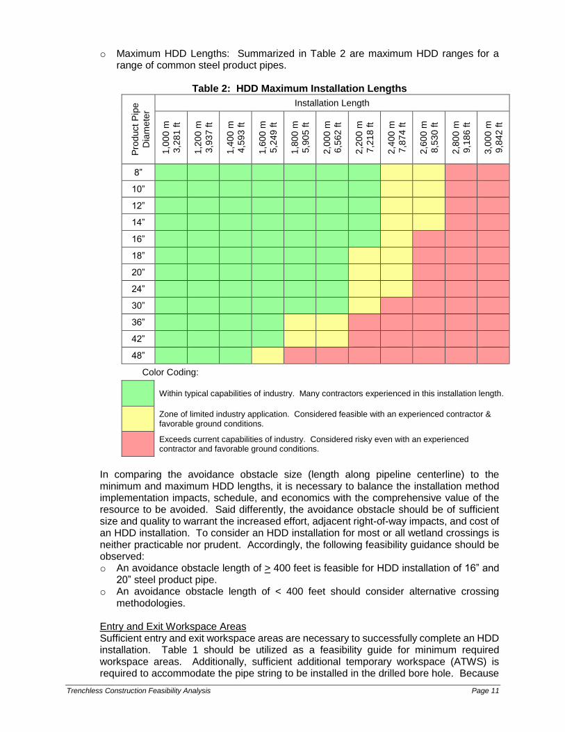
o Maximum HDD Lengths: Summarized in Table 2 are maximum HDD ranges for a range of common steel product pipes.
Table 2: HDD Maximum Installation Lengths
Pro
duct
Pip
e
Dia
mete
r
Installation Length
1,0
00 m
3,2
81 ft
1,2
00 m
3,9
37 ft
1,4
00 m
4,5
93 ft
1,6
00 m
5,2
49 ft
1,8
00 m
5,9
05 ft
2,0
00 m
6,5
62 ft
2,2
00 m
7,2
18 ft
2,4
00 m
7,8
74 ft
2,6
00 m
8,5
30 ft
2,8
00 m
9,1
86 ft
3,0
00 m
9,8
42 ft
8”
10”
12”
14”
16”
18”
20”
24”
30”
36”
42”
48”
Color Coding:
Within typical capabilities of industry. Many contractors experienced in this installation length.
Zone of limited industry application. Considered feasible with an experienced contractor & favorable ground conditions.
Exceeds current capabilities of industry. Considered risky even with an experienced contractor and favorable ground conditions.
In comparing the avoidance obstacle size (length along pipeline centerline) to the minimum and maximum HDD lengths, it is necessary to balance the installation method implementation impacts, schedule, and economics with the comprehensive value of the resource to be avoided. Said differently, the avoidance obstacle should be of sufficient size and quality to warrant the increased effort, adjacent right-of-way impacts, and cost of an HDD installation. To consider an HDD installation for most or all wetland crossings is neither practicable nor prudent. Accordingly, the following feasibility guidance should be observed: o An avoidance obstacle length of > 400 feet is feasible for HDD installation of 16” and
20” steel product pipe. o An avoidance obstacle length of < 400 feet should consider alternative crossing
methodologies. Entry and Exit Workspace Areas Sufficient entry and exit workspace areas are necessary to successfully complete an HDD installation. Table 1 should be utilized as a feasibility guide for minimum required workspace areas. Additionally, sufficient additional temporary workspace (ATWS) is required to accommodate the pipe string to be installed in the drilled bore hole. Because
Trenchless Construction Feasibility Analysis Page 12
the pullback typically is conducted as a single, continuous operation, the ATWS required to accommodate the pipe string is straight, contiguous (i.e., not interrupted by physical obstacles, such as roads or structures), long enough to accommodate the length of the pipe string, and situated behind and largely in line with the HDD alignment. In certain cases, two pipe strings, each approximately one-half the length of the full pipe string, may be used; however, this requires temporary suspension of the pullback operation (to weld the second pullback string to the first pullback string) before completing the pullback operation, and introduces a substantive risk of pullback operation failure.
4.2.3 GEOLOGICAL CONSTRAINTS
A comprehensive analysis of the geological characteristics along a proposed HDD alignment is a vital component of detailed engineering design. This investigative process is divided into three primary components: o General geologic characteristics and formation origins o Detailed soil borings o Hydrogeology General Geologic Characteristics and Formation Origins It is important to have a general understanding of the geologic characteristics and formation origins along the proposed HDD alignment. Understanding the mechanism by which the site was developed, whether aeolian (airborne), colluvial (gravity), alluvial (river), lacustrine (lake), glacial, or marine (saltwater sea) depositional processes will forecast the types of materials to be expected, as well as the potential for anomalous impediments (boulders, cobble fields, buried logs, stumps, etc.) affecting HDD construction. This informational overview may not be representative in localized soil borings. Detailed Soil Borings Soil borings provide the most detailed data regarding geologic conditions. The sampling program for the Project was conducted as follows: o Intervals: Borings were placed at the HDD entry and exit sites and at 1,000-foot
intervals along the bore path to characterize geological conditions. The more borings conducted, the more information available for detailed engineering design.
o Locations: Borings were placed along the proposed HDD alignment, but not within 30 feet of the centerline. Borings taken near the centerline can create a path for inadvertent return of HDD drilling fluid.
o Depth: Borings were taken down to 20 feet below the proposed HDD drill path elevation or until the auger encountered refusal. In addition, bedrock cores were taken from 20% of samples where bedrock was encountered.
Hydrogeology The main hydrogeological issue relates to the presence of artesian conditions. These are typically encountered where impermeable clay or shale bedrock layers overlie permeable water-bearing sands-gravels or sandstone bedrock at depth, forming a confining aquifer. When intersected by the pilot hole, such aquifers may be large-volume sources of groundwater under pressure. As such, HDD mud quality and fluid management problems may result. This situation is typically identified during the soil boring process and potentially mitigated during detailed engineering design. Mitigative measures include casing or cementing off the confined aquifer zone. Geological Feasibility Analysis Soil boring profiles are typically mapped spatially along the proposed HDD alignment. This overlay allows the design engineers to evaluate which specific geologic formations the bore hole will penetrate. Examination of these impacted formations determine the

Trenchless Construction Feasibility Analysis Page 13
feasibility of segments along the bore hole pathway and collectively the overall HDD. The evaluation criteria summarized in Table 3 is typically utilized in the engineering evaluation process.
Table 3: HDD Geological Feasibility Analysis Criteria
Earth Material Type Sieve Analysis Gravel % HDD Feasibility Determination
Very soft to hard clay N/A Good to Excellent
Very loose to very dense sand with or without gravel
traces 0% to 30% Good to Excellent
Very loose to very dense gravelly sand
30% to 50% Marginally Acceptable
Very loose to very dense sandy gravel
50% to 85% Questionable
Very loose to very dense gravel
85% to 100% Unacceptable
Rock N/A Excellent to Unacceptable
Notes: Rock characteristics that affect HDD vary greatly including, but not limited to: o Hardness ○ Strength o Degree of weathering ○ Degree of fracturing o Over burden layer ○ Continuousness
5.0 TECHNICAL FEASIBILITY ANALYSIS
5.1 WETLAND-SPECIFIC TRENCHLESS FEASIBILITY ANALYSIS
As presented in the Alternatives Analysis (Attachment 11, Enclosure E, Part 3), SPLP designed the proposed Project to be co-located (abut and overlap) with existing SPLP pipeline right-of-way and co-located (abut) with other existing utility rights-of-way, adopt major route alternatives to avoid and minimize obvious impacts on other (non-wetland) significant environmental resources and communities, and adopt further quantitative and qualitative impact avoidance and minimization measures in a concerted and successful effort to avoid, minimize, and mitigate site-specific and cumulative impacts to wetlands, as well as waterbodies and other (non-wetland) environmental resources, to the maximum extent practicable. This process resulted in the avoidance, minimization, and mitigation of adverse impacts to wetlands and waterbodies from the Project as a whole by investigating successively more site-specific information regarding potential environmental impacts, and developing alternative routing, locations, and designs to avoid and minimize those potential environmental impacts. Following establishment of the Baseline Route Alternative and associated 200-foot-wide survey corridor (Attachment 11, Enclosure E, Part 3, Section 3.4), SPLP conducted the integrated evaluation of the route via the Management of Change (MOC) Process. This MOC Process considered opportunities to change the Baseline Route Alternative to further avoid and minimize potential environmental impacts, while simultaneously considering potential construction and operational constraints presented by affected landowners, existing land uses, infrastructure obstacles, and other factors affecting use of existing technology, cost, and logistics.
Trenchless Construction Feasibility Analysis Page 14
As presented in the Alternatives Analysis (Attachment 11, Enclosure E, Part 3, Section 5.0), the MOC Process was initiated on a site-specific basis as opportunities or constraints were raised by an Integrated Project Team, consisting of representatives from SPLP project management, engineering, land/right-of-way, and environmental specialists. The MOC Process engaged and solicited input from each member of the Integrated Project Team on a given alternative minor route variation or trenchless construction method (i.e., conventional bore or HDD) under consideration. With the approval from each member of the Integrated Project Team, including environmental, each adopted change was determined to avoid significant impacts on other (non-wetland) environmental resources, to avoid and minimize impacts on wetlands (as well as waterbodies) to the maximum extent practicable, and to be practicable (feasible, constructible, operable) with regard to current technology, cost, and logistics. Implementation of this MOC Process resulted in the evaluation and adoption of minor route variations and trenchless crossings to avoid or minimize: 1) significant impacts on other (non-wetland) environmental resources, 2) permanent palustrine forested (PFO) wetland cover type conversion, and 3) remaining temporary and minor site-specific impacts on wetlands and waterbodies. In response to PADEP comments, wetland (site)-specific trenchless feasibility analysis embodied in the MOC process is presented in the Alternatives Analysis (Attachment 11, Enclosure E, Part 3). This analysis addresses each crossing area (CA) that contains an individual or group of proximate individual wetland (and waterbody) resources that are proposed for open trench pipeline installation; crossing areas determined to be suitable, practicable, and proposed for trenchless construction methods (e.g., conventional bore and HDD) to entirely avoid surface impacts to wetland and other (non-wetland) sensitive environmental resources are presented in the Alternatives Analysis (Attachment 11, Enclosure E, Part 3, Section 5.2). Each crossing area represents a reasonable area of analysis for the consideration of alternative construction techniques (e.g., conventional bore, HDD, and trenching) potentially available based on current technology, cost, and logistics. As presented in the Alternatives Analysis (Attachment 11, Enclosure E, Part 3, Appendix D), the Project contains a total of 349 crossing areas, encompassing numerous wetland and waterbody resource crossings initially proposed for open trench pipeline installation. The Trenchless Construction Feasibility Analysis Matrix (Table 4) herein addresses each of the CAs, as well as additional CAs that address PADEP comments regarding trenchless crossing areas.
5.2 STREAM-SPECIFIC TRENCHLESS FEASIBILITY ANALYSIS
As requested by PADEP in it is technical deficiency comments, SPLP evaluated a total of 16 site-specific areas of proposed stream crossings not associated with any wetland crossing area (each designated with a unique Stream Area [SA] identification number). Specifically, SPLP evaluated each SA with regard to PADEP’s site-specific comments regarding use of new or the potential extension of the length of currently proposed trenchless construction techniques, work space reconfiguration, or other actions to further avoid or minimize impacts on streams, which is provided in the Alternatives Analysis (Attachment 11, Enclosure E, Part 3, Appendix E). For each designated SA wherein PADEP commented regarding use of new or the potential extension of the length of currently proposed trenchless construction techniques (12 of the 16 stream-specific areas), a stream-specific trenchless feasibility analysis is presented in the matrix (Table 4).

Trenchless Construction Feasibility Analysis Page 15
5.3 TRENCHLESS FEASIBILITY ANALYSIS MATRIX
For each CA and SA, a wetland or stream (site)-specific trenchless feasibility analysis was conducted and is presented in the form of a trenchless feasibility analysis matrix (Table 4). For each CA and SA, the trenchless feasibility analysis matrix assesses the technical feasibility of conducting a CAB or HDD construction technique to cross the subject wetland and/or stream resources in consideration of existing site-specific conditions. Specifically for each CA and SA, the matrix (Table 4) presents the CA or SA identification (ID) number, list of wetlands and streams encompassed within the CA or SA, and the minimum length of the CA or SA (encompassing the subject wetlands and/or streams). For each CA and SA, the CAB technical feasibility analysis (Table 4):
identifies the estimated length of a CAB needed to cross the CA or SA resources
considering site-specific conditions;
assesses whether the length of the bore is within the technical capabilities of CAB
construction technology (i.e., not greater than 390 feet in length);
assesses whether existing topography is conducive to supporting CAB
construction technology;
assesses whether sufficient additional temporary work space (ATWS) is available
in proximity to the CAB to support bore pit excavation, soil storage, equipment,
personnel, and associated CAB activities in a safe and prudent manner;
assesses whether sufficient access is available in proximity to the CAB to support
equipment and personnel transport throughout the duration of CAB construction in
a safe and prudent manner; and
based on the above evaluation criteria, assesses whether use of the CAB
construction technology is technically feasible.
For each CA and SA, the HDD technical feasibility analysis (Table 4):
identifies the estimated length of an HDD needed to cross the CA or SA resources
considering site-specific conditions, using a minimum HDD length of 1,160 feet;
assesses whether existing topography is conducive to supporting HDD
construction technology;
assesses whether the elevation change between an HDD entry site and exit site
is conducive to supporting HDD construction technology (e.g., similarity between
the entry and exit site elevations to minimize risk of dry bore hole conditions);
assesses whether the required HDD path geometry (vertical curvature) is feasible
(e.g., entry and exit pit locations supportive of required entry and exit angles and
pipe radius tolerances);
assesses whether sufficient pipe string pullback area and ATWS is available in
proximity to the HDD to support entry and exit sites, pipe string pullback,
equipment, personnel, and associated HDD activities in a safe and prudent
manner;
assesses whether sufficient access is available in proximity to the HDD to support
equipment and personnel transport throughout the duration of HDD construction
in a safe and prudent manner; and
based on the above evaluation criteria, assesses whether use of the HDD
construction technology is technically feasible.
Trenchless Construction Feasibility Analysis Page 16
For each CAB and HDD technical feasibility criterion evaluated, a determination of technical feasibility is noted based on the analysis of existing information. Determinations include:
Yes (“Y”), meaning is technically feasible;
No (“N”), meaning is not technically feasible; or
Potentially (“P”), meaning is potentially technically feasible, but is considered
marginally feasible considering site-specific conditions, current technology, and
logistics, and/or requires additional site-specific information (e.g., bore profile) to
confirm technical feasibility, based on existing information.
In the event any of the evaluation criteria fail (“N”) the technical feasibility analysis, then the use of the subject trenchless construction technology is also determined to be not technically feasible. In the event none of the evaluation criteria fail (“N”), but any of the evaluation criteria are determined to be potentially technically feasible (“P”), then the use of the subject trenchless construction technology is also determined to be potentially technically feasible. Only in the event all of the evaluation criteria pass (“Y”) is the use of the subject trenchless construction technology also determined to be technically feasible. In addition to the CAB and HDD technical feasibility analysis, the matrix (Table 4) presents the estimated minimum cost for use of the CAB and HDD construction technology at each CA and SA. The estimated minimum construction cost is calculated for each case in which CAB or HDD was determined to be technically feasible (“Y”) or potentially technically feasible (“P”). The estimated minimum construction cost is calculated for the 20-inch-diameter pipeline only, and includes: 1) the average cost per linear foot of pipeline (for the estimated length of the CAB or HDD crossing), and 2) the “move around” cost, which entails the movement (halting, loading, transport, and unloading) of all construction equipment and personnel around the CAB or HDD crossing (entry and exit sites) for the duration of pipeline construction. The cost for the 16-inch-diameter pipeline is not calculated, but would include a similar cost per linear foot of pipeline (about 6% less than 20-inch-diameter pipeline cost) and the “move around” cost. Where applicable, this estimated minimum cost information is further evaluated in the wetland and stream (site)-specific practicable alternatives analyses presented in the Alternatives Analysis (Attachment 11, Enclosure E, Part 3) to assess the practicability of use of the CAB and HDD construction technology at each CA and SA.
5.4 SUMMARY OF TRENCHLESS FEASIBILITY ANALYSIS RESULTS
As detailed in the CAB and HDD technical feasibility analysis matrix (Table 4), a total 393 areas (381 CAs and 12 SAs) were evaluated for the technical feasibility of conducting CAB and HDD construction technology. This includes the CAs discussed in the Alternatives Analysis (Attachment 11, Enclosure E, Part 3) and additional CAs assessed where Based on this analysis, use of the CAB construction technology was determined to be not technically feasible (“N”) for 357 of the 393 areas. Use of the CAB construction technology was determined to be:
technically feasible (“Y”) for eight (8) CAs (CA-335, CA-346, CA-352, CA-356, CA-
379, CA-380, CA-394, CA-395, CA-398);
technically feasible (“Y”) for one (1) SA (SA-010, which is in an area already
proposed for use of the CAB construction technology);
potentially technically feasible (“P”) for 26 CAs (CA-004, CA-036, CA-139, CA-208,
CA-209, CA-212, CA-213, CA-218, CA-237, CA-241, CA-244, CA-282, CA-290,
CA-294, CA-301, CA-302, CA-303, CA-304, CA-309, CA-366, CA-367, CA-372,
CA-411, CA-413, CA-435, and CA-436); and
Trenchless Construction Feasibility Analysis Page 17
potentially technically feasible (“P”) for one (1) SA (SA-011).
Based on this analysis, use of the HDD construction technology was determined to be not technically feasible (“N”) for 380 of the 393 areas. Use of the CAB construction technology was determined to be:
technically feasible (“Y”) for six (6) CAs (CA-009, CA-016, CA-075, CA-075, CA-
196, and CA-411, all of which are in areas proposed for use of the HDD
construction technology);
technically feasible (“Y”) for two (2) SAs (SA-008 and SA-015, both of which are in
areas proposed for use of the HDD construction technology);
potentially technically feasible (“P”) for three (3) CAs (CA-200; CA-352, which is
proposed for HDD construction technology but requires travel lane and pullback
string access across the wetlands and stream in the CA; and CA-353); and
potentially technically feasible (“P”) for two (2) SAs (SA-010, which is proposed for
CAB construction technology, and SA-011).
Trenchless Construction Feasibility Analysis Page 18
Table 4: Trenchless Construction Feasibility Analysis Matrix

TABLE 4
Trenchless Construction Feasibility Analysis Matrix
Pennsylvania Pipeline Project
Crossing
Area ID Wetlands Streams
Minimum
Length of
Crossing Area
(feet)
Estimated
Bore Length
(feet)
Bore Crossing
Length less
than 390'
Topography
Conducive to
Bore
Sufficient
ATWS
Available
Sufficient
Access (Travel
Lane
Required)
Bore
Technically
FeasibleEstimated
HDD Length
Topography
Conducive to
HDD
Elevation
Change
Conducive to
HDD
HDD is
Geometrically
Feasible
Sufficient HDD
Pullback and
ATWS
Available
Sufficient
Access (Travel
Lane
Required)2
HDD
Technically
Feasible Minimum Bore Cost Minimum HDD Cost
CA-002 T1 130 150 Y Y N N N 1300 N N N N N N n/a n/a
CA-003 W42 40 60 Y Y N N N 1160 N N N N N N n/a n/a
CA-004 A20A 70 90 Y Y P Y P 1160 N N N N N N 496,627$ n/a
CA-005 T2 22 125 Y N N N N 1300 N N N N N N n/a n/a
CA-006 W5 S8 30 50 Y N N Y N 1600 N N N N N N n/a n/a
CA-008 W8, W9 S14, S15 50 70 Y N N Y N 1160 N p P N Y N n/a n/a
CA-009 W43 S131, S132 735 750 N N 725 Y Y Y Y Y Y n/a 1,864,181$
CA-010 W204 50 70 Y N N N N 1160 N N Y N N N n/a n/a
CA-011 W44 S139 45 65 Y Y N N N 1200 N N N N N N n/a n/a
CA-012 W12 S19, S20 40 60 Y N N N N 1160 N N N N N N n/a n/a
CA-013 W37 100 120 Y N N N N 1160 Y Y N N N N n/a n/a
CA-014 W13 S22 90 110 Y Y N N N 1160 N N N N N N n/a n/a
CA-015 W14 25 45 Y Y N N N 1160 N N N N N N n/a n/a
CA-016 W38 40 1100 N N 1176 Y Y Y Y Y Y n/a 2,827,841$
CA-017 W62 S143, S219 130 150 Y N N N N 2600 Y N Y N N N n/a n/a
CA-018 W63 285 305 Y Y N N N 1300 Y Y Y N N N n/a n/a
CA-019 W46-1 80 100 Y P P N N 1500 Y Y Y N N N n/a n/a
CA-020 CS1 S-CS1 80 100 Y N N N N 1160 N N N N N N n/a n/a
CA-024 SZ6 90 110 Y N N N N 1600 N N N N N N n/a n/a
CA-025 W48PEM-1 S173, S174 30 50 Y N N N N 1300 Y Y Y N N N n/a n/a
CA-026 W49 S175 80 100 Y Y N N N 1200 p p N N N N n/a n/a
CA-028 W71 S235 15 35 Y Y P N N 1500 Y P Y P N N n/a n/a
CA-029 W52 40 60 Y Y N N N 1500 N N N N N N n/a n/a
CA-031 W55, W56
S189, S190,
S191 530 550 N N 1200 N N N N N N n/a n/a
CA-032 W54 S188 30 50 Y N N N N 1160 N N N N N N n/a n/a
CA-033 W58 20 40 Y N N N N 1600 N N N N N N n/a n/a
CA-034 W57 20 40 Y N N N N 1600 N N N N N N n/a n/a
CA-035 W69, W70 310 330 Y Y N N N 1160 Y Y Y N N N n/a n/a
CA-036 W60 S210 40 60 Y Y P Y P 1300 Y Y Y N P N 436,104$ n/a
CA-037 Pond-XX16 S204, S205 150 170 Y N N N N 1300 N N N N p N n/a n/a
CA-038 P25 S-P41, S-P42 120 115 Y Y N N N 1700 Y N Y N N N n/a n/a
CA-039 P28 S-P43 270 270 Y Y N N N 1900 Y N Y N N N n/a n/a
CA-040 P29 S-P44, S-P45 60 60 Y Y N P N 1900 Y N Y N N N n/a n/a
CA-041 P30 105 105 Y Y N P N 1900 Y N Y N N N n/a n/a
CA-042 P33, P35 S-P49, S-P50 300 90 Y P N N N 2400 N N N N p N n/a n/a
CA-045 M78
S-M105, S-
M106 55 55 Y N N N N 2100 Y N Y N N N n/a n/a
CA-046 M77 25 25 Y P N N N 2100 Y P Y N N N n/a n/a
CA-049 M75 S-M102 195 195 Y N N N N 1700 Y N Y N N N n/a n/a
CA-050 M74, P26, P27 S-P36 210 280 Y Y N N N 1600 N N N N N N n/a n/a
Conventional Auger Bore Construction Technology Horizontal Directional Drill Construction Technology
Sunoco Pipeline, L.P.
Pennsylvania Pipeline Project 1 November 18, 2016
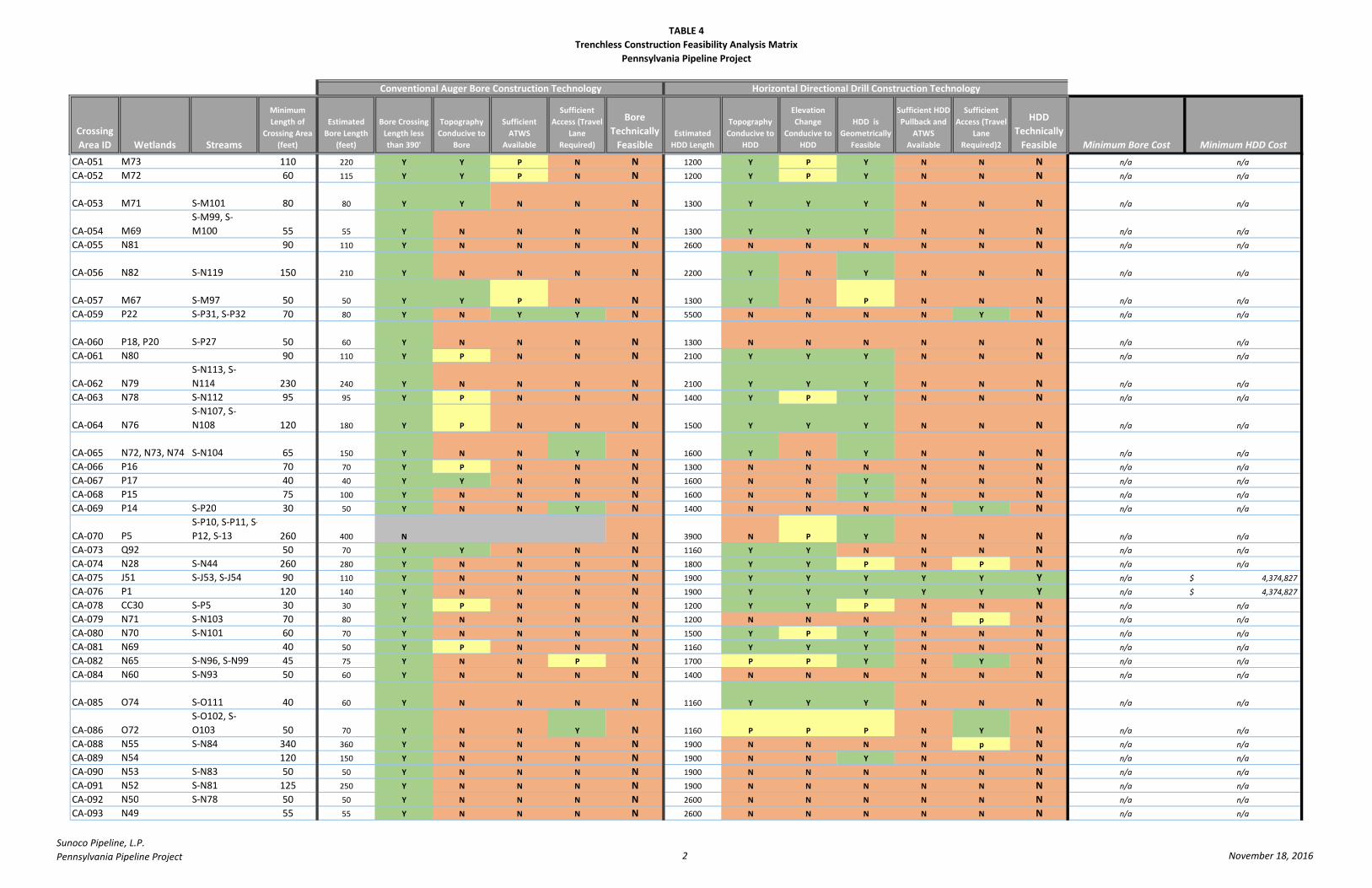
TABLE 4
Trenchless Construction Feasibility Analysis Matrix
Pennsylvania Pipeline Project
Crossing
Area ID Wetlands Streams
Minimum
Length of
Crossing Area
(feet)
Estimated
Bore Length
(feet)
Bore Crossing
Length less
than 390'
Topography
Conducive to
Bore
Sufficient
ATWS
Available
Sufficient
Access (Travel
Lane
Required)
Bore
Technically
FeasibleEstimated
HDD Length
Topography
Conducive to
HDD
Elevation
Change
Conducive to
HDD
HDD is
Geometrically
Feasible
Sufficient HDD
Pullback and
ATWS
Available
Sufficient
Access (Travel
Lane
Required)2
HDD
Technically
Feasible Minimum Bore Cost Minimum HDD Cost
Conventional Auger Bore Construction Technology Horizontal Directional Drill Construction Technology
CA-051 M73 110 220 Y Y P N N 1200 Y P Y N N N n/a n/a
CA-052 M72 60 115 Y Y P N N 1200 Y P Y N N N n/a n/a
CA-053 M71 S-M101 80 80 Y Y N N N 1300 Y Y Y N N N n/a n/a
CA-054 M69
S-M99, S-
M100 55 55 Y N N N N 1300 Y Y Y N N N n/a n/a
CA-055 N81 90 110 Y N N N N 2600 N N N N N N n/a n/a
CA-056 N82 S-N119 150 210 Y N N N N 2200 Y N Y N N N n/a n/a
CA-057 M67 S-M97 50 50 Y Y P N N 1300 Y N P N N N n/a n/a
CA-059 P22 S-P31, S-P32 70 80 Y N Y Y N 5500 N N N N Y N n/a n/a
CA-060 P18, P20 S-P27 50 60 Y N N N N 1300 N N N N N N n/a n/a
CA-061 N80 90 110 Y P N N N 2100 Y Y Y N N N n/a n/a
CA-062 N79
S-N113, S-
N114 230 240 Y N N N N 2100 Y Y Y N N N n/a n/a
CA-063 N78 S-N112 95 95 Y P N N N 1400 Y P Y N N N n/a n/a
CA-064 N76
S-N107, S-
N108 120 180 Y P N N N 1500 Y Y Y N N N n/a n/a
CA-065 N72, N73, N74 S-N104 65 150 Y N N Y N 1600 Y N Y N N N n/a n/a
CA-066 P16 70 70 Y P N N N 1300 N N N N N N n/a n/a
CA-067 P17 40 40 Y Y N N N 1600 N N Y N N N n/a n/a
CA-068 P15 75 100 Y N N N N 1600 N N Y N N N n/a n/a
CA-069 P14 S-P20 30 50 Y N N Y N 1400 N N N N Y N n/a n/a
CA-070 P5
S-P10, S-P11, S-
P12, S-13 260 400 N N 3900 N P Y N N N n/a n/a
CA-073 Q92 50 70 Y Y N N N 1160 Y Y N N N N n/a n/a
CA-074 N28 S-N44 260 280 Y N N N N 1800 Y Y P N P N n/a n/a
CA-075 J51 S-J53, S-J54 90 110 Y N N N N 1900 Y Y Y Y Y Y n/a 4,374,827$
CA-076 P1 120 140 Y N N N N 1900 Y Y Y Y Y Y n/a 4,374,827$
CA-078 CC30 S-P5 30 30 Y P N N N 1200 Y Y P N N N n/a n/a
CA-079 N71 S-N103 70 80 Y N N N N 1200 N N N N p N n/a n/a
CA-080 N70 S-N101 60 70 Y N N N N 1500 Y P Y N N N n/a n/a
CA-081 N69 40 50 Y P N N N 1160 Y Y Y N N N n/a n/a
CA-082 N65 S-N96, S-N99 45 75 Y N N P N 1700 P P Y N Y N n/a n/a
CA-084 N60 S-N93 50 60 Y N N N N 1400 N N N N N N n/a n/a
CA-085 O74 S-O111 40 60 Y N N N N 1160 Y Y Y N N N n/a n/a
CA-086 O72
S-O102, S-
O103 50 70 Y N N Y N 1160 P P P N Y N n/a n/a
CA-088 N55 S-N84 340 360 Y N N N N 1900 N N N N p N n/a n/a
CA-089 N54 120 150 Y N N N N 1900 N N Y N N N n/a n/a
CA-090 N53 S-N83 50 50 Y N N N N 1900 N N N N N N n/a n/a
CA-091 N52 S-N81 125 250 Y N N N N 1900 N N N N N N n/a n/a
CA-092 N50 S-N78 50 50 Y N N N N 2600 N N N N N N n/a n/a
CA-093 N49 55 55 Y N N N N 2600 N N N N N N n/a n/a
Sunoco Pipeline, L.P.
Pennsylvania Pipeline Project 2 November 18, 2016
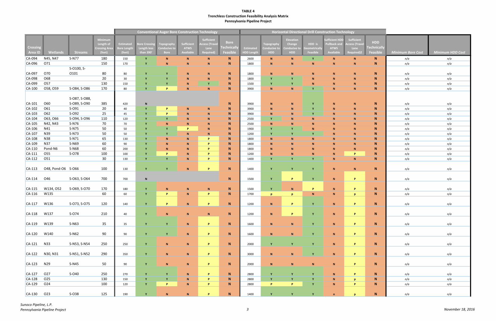
TABLE 4
Trenchless Construction Feasibility Analysis Matrix
Pennsylvania Pipeline Project
Crossing
Area ID Wetlands Streams
Minimum
Length of
Crossing Area
(feet)
Estimated
Bore Length
(feet)
Bore Crossing
Length less
than 390'
Topography
Conducive to
Bore
Sufficient
ATWS
Available
Sufficient
Access (Travel
Lane
Required)
Bore
Technically
FeasibleEstimated
HDD Length
Topography
Conducive to
HDD
Elevation
Change
Conducive to
HDD
HDD is
Geometrically
Feasible
Sufficient HDD
Pullback and
ATWS
Available
Sufficient
Access (Travel
Lane
Required)2
HDD
Technically
Feasible Minimum Bore Cost Minimum HDD Cost
Conventional Auger Bore Construction Technology Horizontal Directional Drill Construction Technology
CA-094 N45, N47 S-N77 180 150 Y N N N N 2600 N N Y N N N n/a n/a
CA-096 O71 150 170 Y N N N N 1800 N N N N N N n/a n/a
CA-097 O70
S-O100, S-
O101 80 80 Y Y N N N 1800 N N N N N N n/a n/a
CA-098 O68 20 30 Y Y N N N 1800 Y Y N N N N n/a n/a
CA-099 O57 130 150 Y Y N Y N 1500 Y Y N N N N n/a n/a
CA-100 O58, O59 S-O84, S-O86 170 80 Y P N N N 3900 N N Y N N N n/a n/a
CA-101 O60
S-O87, S-O88,
S-O89, S-O90 385 420 N N 3900 N N Y N N N n/a n/a
CA-102 O61 S-O91 20 40 Y P N N N 3900 N N Y N N N n/a n/a
CA-103 O62 S-O92 25 45 Y P N N N 3900 N N Y N N N n/a n/a
CA-104 O63, O66 S-O94, S-O96 110 120 Y Y N N N 2500 Y N N N N N n/a n/a
CA-105 N42, N43 S-N76 70 70 Y N N N N 2500 N N N N N N n/a n/a
CA-106 N41 S-N75 50 50 Y Y P N N 1900 Y Y N N N N n/a n/a
CA-107 N39 S-N73 50 50 Y Y N N N 1200 Y Y Y N N N n/a n/a
CA-108 N38 S-N71 65 130 Y N N P N 1800 N N N N N N n/a n/a
CA-109 N37 S-N69 60 90 Y N N P N 1800 N N N N N N n/a n/a
CA-110 Pond-N6 S-N68 60 200 Y N N P N 1800 N N N N N N n/a n/a
CA-111 O55 S-O78 100 100 Y P N P N 1200 N N N N P N n/a n/a
CA-112 O51 30 130 Y Y N P N 1400 Y Y Y N N N n/a n/a
CA-113 O48, Pond-O6 S-O66 100 130 Y Y N P N 1400 Y Y Y N N N n/a n/a
CA-114 O46 S-O63, S-O64 700 700 N N 1500 Y P Y N P N n/a n/a
CA-115 W134, O52 S-O69, S-O70 170 180 Y N N N N 1500 Y N P N P N n/a n/a
CA-116 W135 60 60 Y P N P N 1700 p p N N p N n/a n/a
CA-117 W136 S-O73, S-O75 120 140 Y P N P N 1200 N P Y N P N n/a n/a
CA-118 W137 S-O74 210 40 Y N N N N 1200 N P Y N P N n/a n/a
CA-119 W139 S-N63 35 35 Y Y N P N 1600 N N Y N P N n/a n/a
CA-120 W140 S-N62 90 90 Y Y N P N 1600 N N Y N P N n/a n/a
CA-121 N33 S-N53, S-N54 250 250 Y N N P N 2000 Y Y Y N P N n/a n/a
CA-122 N30, N31 S-N51, S-N52 290 350 Y N N P N 3000 N N Y N P N n/a n/a
CA-123 N29 S-N45 50 90 Y N N P N 2000 N N N N P N n/a n/a
CA-127 O27 S-O40 250 270 Y Y N P N 2800 Y Y Y N P N n/a n/a
CA-128 O25 130 150 Y Y N P N 2800 Y Y Y N p N n/a n/a
CA-129 O24 100 120 Y P N P N 2800 P P Y N P N n/a n/a
CA-130 O23 S-O38 125 190 Y N N P N 1400 Y Y Y n p N n/a n/a
Sunoco Pipeline, L.P.
Pennsylvania Pipeline Project 3 November 18, 2016

TABLE 4
Trenchless Construction Feasibility Analysis Matrix
Pennsylvania Pipeline Project
Crossing
Area ID Wetlands Streams
Minimum
Length of
Crossing Area
(feet)
Estimated
Bore Length
(feet)
Bore Crossing
Length less
than 390'
Topography
Conducive to
Bore
Sufficient
ATWS
Available
Sufficient
Access (Travel
Lane
Required)
Bore
Technically
FeasibleEstimated
HDD Length
Topography
Conducive to
HDD
Elevation
Change
Conducive to
HDD
HDD is
Geometrically
Feasible
Sufficient HDD
Pullback and
ATWS
Available
Sufficient
Access (Travel
Lane
Required)2
HDD
Technically
Feasible Minimum Bore Cost Minimum HDD Cost
Conventional Auger Bore Construction Technology Horizontal Directional Drill Construction Technology
CA-131 O21 160 200 Y Y N P N 1400 Y Y Y N P N n/a n/a
CA-132 O20 S-O37 120 130 Y N N p N 2300 P y N N P N n/a n/a
CA-133 O42 S-O56 240 260 Y N N P N 1500 P Y Y N P N n/a n/a
CA-134 O37, O16
S-O30, S-O31,
S-O45, S-O48 1100 1200 N N 3900 N N N N P N n/a n/a
CA-136 CC6, CC7
S-CC4, S-CC5,
S-CC6 280 300 Y N N P N 1900 Y N Y N P N n/a n/a
CA-137 CC20, CC21 225 245 Y N N P N 4200 Y Y Y N P N n/a n/a
CA-138
CC13, CC15,
CC16, C18,
CC19 620 660 N N 4200 Y Y Y N P N n/a n/a
CA-139 CC12 220 240 Y Y N P N 4200 Y Y Y N P N n/a n/a
CA-140 CC4 S-CC3 205 550 N N 4200 Y Y Y N P N n/a n/a
CA-141 CC2 50 70 Y Y N N N 4200 Y Y Y N P N n/a n/a
CA-142 O15 100 120 Y Y N P N 1200 Y Y Y N P N n/a n/a
CA-143 O12 S-O21, S-O23 365 395 N N 3000 N N N N p N n/a n/a
CA-144 O9, O10
S-O18, S-O19,
S-O20 490 510 N N 3100 N N Y N P N n/a n/a
CA-145 O8 480 500 N N 3100 N N Y N P N n/a n/a
CA-147 N2 S-N4 50 70 Y Y N P N 1900 N N Y N P N n/a n/a
CA-148 N4 S-N10 220 230 Y Y N P N 1800 N Y Y N P N n/a n/a
CA-149 N5, N6 S-N13, S-N14 120 150 Y N N P N 1800 N Y Y N P N n/a n/a
CA-152 N17 S-N33 210 230 Y N N P N 1700 Y N Y N P N n/a n/a
CA-153 N15 S-N29, S-N30 140 160 Y N N P N 2700 N N N N N N n/a n/a
CA-154 N14 250 270 Y N N N N 2700 N N N N N N n/a n/a
CA-155 N12
S-N25, S-N26,
S-N27, S-N28 405 250 Y N N P N 2700 N N N N N N n/a n/a
CA-156 N11 30 50 Y N N P N 2600 N N N N N N n/a n/a
CA-157 N10 S-N21, S-N22 90 110 Y N N P N 2600 N N N N N N n/a n/a
CA-158 N9 150 170 Y Y N P N 2600 N N N N N N n/a n/a
CA-159 N8 S-N18 150 170 Y N N N N 2600 N N N N N N n/a n/a
CA-160 O6 120 135 Y Y N P N 2000 Y N Y N P N n/a n/a
CA-161 O5 S-O11, S-O12 110 130 Y P N P N 2000 Y N Y N P N n/a n/a
CA-162 O4
S-O7, S-O8, S-
O9 120 140 Y N N P N 1500 P Y N N P N n/a n/a
Sunoco Pipeline, L.P.
Pennsylvania Pipeline Project 4 November 18, 2016
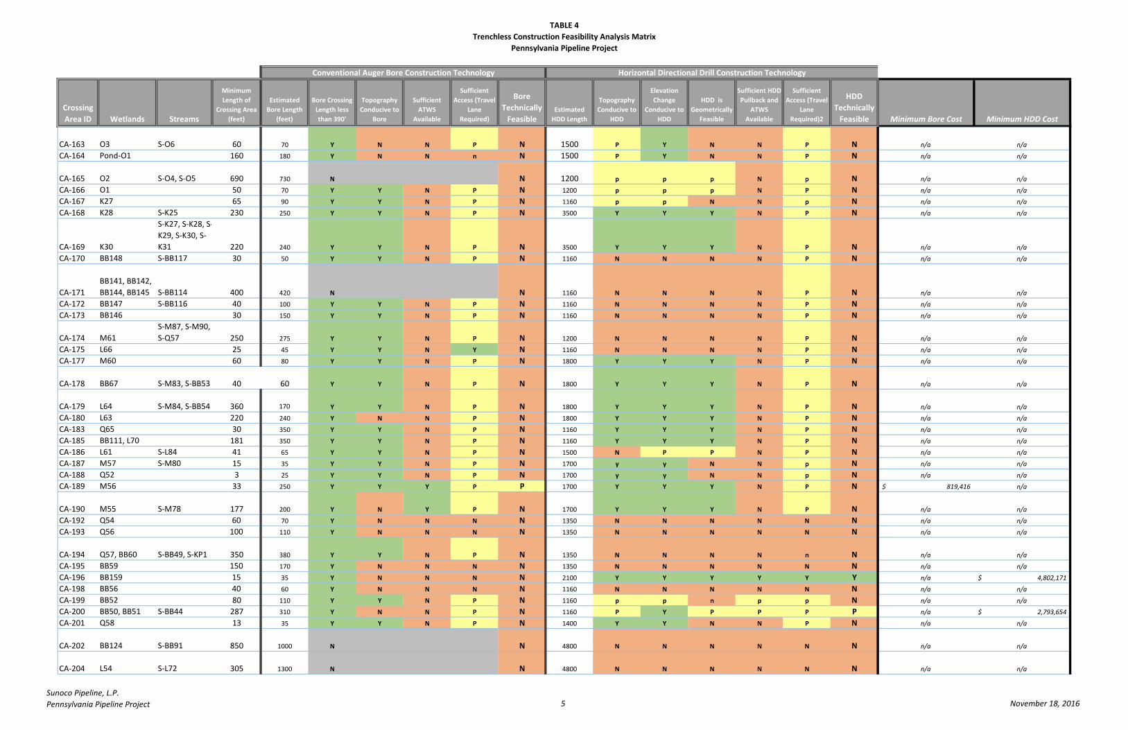
TABLE 4
Trenchless Construction Feasibility Analysis Matrix
Pennsylvania Pipeline Project
Crossing
Area ID Wetlands Streams
Minimum
Length of
Crossing Area
(feet)
Estimated
Bore Length
(feet)
Bore Crossing
Length less
than 390'
Topography
Conducive to
Bore
Sufficient
ATWS
Available
Sufficient
Access (Travel
Lane
Required)
Bore
Technically
FeasibleEstimated
HDD Length
Topography
Conducive to
HDD
Elevation
Change
Conducive to
HDD
HDD is
Geometrically
Feasible
Sufficient HDD
Pullback and
ATWS
Available
Sufficient
Access (Travel
Lane
Required)2
HDD
Technically
Feasible Minimum Bore Cost Minimum HDD Cost
Conventional Auger Bore Construction Technology Horizontal Directional Drill Construction Technology
CA-163 O3 S-O6 60 70 Y N N P N 1500 P Y N N P N n/a n/a
CA-164 Pond-O1 160 180 Y N N n N 1500 P Y N N P N n/a n/a
CA-165 O2 S-O4, S-O5 690 730 N N 1200 p p p N p N n/a n/a
CA-166 O1 50 70 Y Y N P N 1200 p p p N P N n/a n/a
CA-167 K27 65 90 Y Y N P N 1160 p p N N p N n/a n/a
CA-168 K28 S-K25 230 250 Y Y N P N 3500 Y Y Y N P N n/a n/a
CA-169 K30
S-K27, S-K28, S-
K29, S-K30, S-
K31 220 240 Y Y N P N 3500 Y Y Y N P N n/a n/a
CA-170 BB148 S-BB117 30 50 Y Y N P N 1160 N N N N P N n/a n/a
CA-171
BB141, BB142,
BB144, BB145 S-BB114 400 420 N N 1160 N N N N P N n/a n/a
CA-172 BB147 S-BB116 40 100 Y Y N P N 1160 N N N N P N n/a n/a
CA-173 BB146 30 150 Y Y N P N 1160 N N N N P N n/a n/a
CA-174 M61
S-M87, S-M90,
S-Q57 250 275 Y Y N P N 1200 N N N N P N n/a n/a
CA-175 L66 25 45 Y Y N Y N 1160 N N N N P N n/a n/a
CA-177 M60 60 80 Y Y N P N 1800 Y Y Y N P N n/a n/a
CA-178 BB67 S-M83, S-BB53 40 60 Y Y N P N 1800 Y Y Y N P N n/a n/a
CA-179 L64 S-M84, S-BB54 360 170 Y Y N P N 1800 Y Y Y N P N n/a n/a
CA-180 L63 220 240 Y N N P N 1800 Y Y Y N P N n/a n/a
CA-183 Q65 30 350 Y Y N P N 1160 Y Y Y N P N n/a n/a
CA-185 BB111, L70 181 350 Y Y N P N 1160 Y Y Y N P N n/a n/a
CA-186 L61 S-L84 41 65 Y Y N P N 1500 N P P N P N n/a n/a
CA-187 M57 S-M80 15 35 Y Y N P N 1700 y y N N p N n/a n/a
CA-188 Q52 3 25 Y Y N P N 1700 y y N N p N n/a n/a
CA-189 M56 33 250 Y Y Y P P 1700 Y Y Y N P N 819,416$ n/a
CA-190 M55 S-M78 177 200 Y N Y P N 1700 Y Y Y N P N n/a n/a
CA-192 Q54 60 70 Y N N N N 1350 N N N N N N n/a n/a
CA-193 Q56 100 110 Y N N N N 1350 N N N N N N n/a n/a
CA-194 Q57, BB60 S-BB49, S-KP1 350 380 Y Y N P N 1350 N N N N n N n/a n/a
CA-195 BB59 150 170 Y N N N N 1350 N N N N N N n/a n/a
CA-196 BB159 15 35 Y N N N N 2100 Y Y Y Y Y Y n/a 4,802,171$
CA-198 BB56 40 60 Y N N N N 1160 N N N N N N n/a n/a
CA-199 BB52 80 110 Y Y N P N 1160 p p n p p N n/a n/a
CA-200 BB50, BB51 S-BB44 287 310 Y N N P N 1160 P Y P P P P n/a 2,793,654$
CA-201 Q58 13 35 Y Y N P N 1400 Y Y N N P N n/a n/a
CA-202 BB124 S-BB91 850 1000 N N 4800 N N N N N N n/a n/a
CA-204 L54 S-L72 305 1300 N N 4800 N N N N N N n/a n/a
Sunoco Pipeline, L.P.
Pennsylvania Pipeline Project 5 November 18, 2016

TABLE 4
Trenchless Construction Feasibility Analysis Matrix
Pennsylvania Pipeline Project
Crossing
Area ID Wetlands Streams
Minimum
Length of
Crossing Area
(feet)
Estimated
Bore Length
(feet)
Bore Crossing
Length less
than 390'
Topography
Conducive to
Bore
Sufficient
ATWS
Available
Sufficient
Access (Travel
Lane
Required)
Bore
Technically
FeasibleEstimated
HDD Length
Topography
Conducive to
HDD
Elevation
Change
Conducive to
HDD
HDD is
Geometrically
Feasible
Sufficient HDD
Pullback and
ATWS
Available
Sufficient
Access (Travel
Lane
Required)2
HDD
Technically
Feasible Minimum Bore Cost Minimum HDD Cost
Conventional Auger Bore Construction Technology Horizontal Directional Drill Construction Technology
CA-205 L46, L48 S-BB96, S-L69 180 200 Y Y N P N 1160 Y Y N N P N n/a n/a
CA-206 L44 38 80 Y Y N P N 1160 N N N N p N n/a n/a
CA-207 L43 53 150 Y Y N P N 1160 N N N N N N n/a n/a
CA-208 L42 115 160 Y Y Y P P 1160 N N N N N N 637,847$ n/a
CA-209 L40 30 160 Y Y Y P P 1160 N N N N N N 637,847$ n/a
CA-212 L35 18 160 Y Y Y P P 1160 Y Y Y N P N 637,847$ n/a
CA-213 M23 S-L58 60 160 Y Y Y P P 1160 Y Y Y N P N 637,847$ n/a
CA-214 L31, L32
S-L50, S-L51, S-
L52 520 565 N N 1200 P P Y N P N n/a n/a
CA-215 Y13 20 40 Y N N N N 1200 N N N N N N n/a n/a
CA-216 Y14 S-Y22 90 110 Y Y N P N 1160 Y Y N N P N n/a n/a
CA-217 L36 S-L57 70 175 Y Y N P N 1250 Y Y Y N P N n/a n/a
CA-218 CC28, Y7, Y8 S-Y6, S-Y7 50 75 Y Y Y P P 1700 N N N N N N 466,366$ n/a
CA-219 Y12
S-Y18, S-Y19, S-
Y20, S-JH2 775 800 N N 1300 N N N N p N n/a n/a
CA-220 S-BB108 4 50 Y Y N P N 1300 N N N N N N n/a n/a
CA-221 L29 S-L47 12 70 Y Y N P N 1160 P Y Y N P N n/a n/a
CA-222 L28 60 85 Y Y N P N 1160 Y Y Y N P N n/a n/a
CA-223 L24 S-L41 310 340 Y N N P N 1160 P Y N N p N n/a n/a
CA-225 M17
S-M18, S-M19,
S-M20 500 520 N N 1250 Y Y Y N P N n/a n/a
CA-226 M15 S-M16, S-M17 115 150 Y p N P N 1200 N N N N p N n/a n/a
CA-227 M13, M14 S-M15 30 110 Y Y N P N 1200 N N N N N N n/a n/a
CA-228 L21 380 400 N N 2800 N N N N N N n/a n/a
CA-229 L18, L20, L33 S-L33, S-L34 135 200 Y Y N P N 3000 Y Y N N P N n/a n/a
CA-230 L16, L17 S-L31 260 320 Y Y N P N 2000 Y Y Y N P N n/a n/a
CA-231 M7 S-M7 75 100 Y p N P N 1160 P P P N P N n/a n/a
CA-232 M8 25 90 Y Y N P N 1160 Y Y P N P N n/a n/a
CA-233 M9 S-M8 40 60 Y p N P N 1160 P Y Y N P N n/a n/a
CA-234 M10
S-M9, S-M10,
S-M11 65 90 Y Y N P N 1200 P P Y N P N n/a n/a
CA-235 M12 145 165 Y N N N N 1160 p Y Y N N N n/a n/a
CA-236 CC27 50 70 Y Y N P N 1160 Y Y Y N P N n/a n/a
CA-237 L15 30 60 Y Y Y P P 1160 Y Y Y N P N 436,104$ n/a
CA-238 L11, L12, L13 S-JH4 250 270 Y Y N P N 1500 Y Y Y N P N n/a n/a
CA-239 L14 S-L22 60 80 Y Y N P N 1500 Y Y Y N P N n/a n/a
CA-240 M6 80 100 Y Y N P N 1160 Y Y Y N P N n/a n/a
CA-241 M3 S-M3 18 130 Y Y Y P P 1160 Y Y N N P N 577,324$ n/a
Sunoco Pipeline, L.P.
Pennsylvania Pipeline Project 6 November 18, 2016
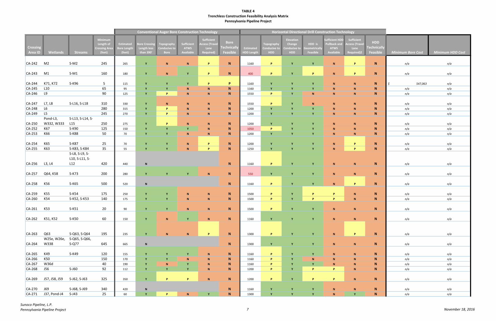
TABLE 4
Trenchless Construction Feasibility Analysis Matrix
Pennsylvania Pipeline Project
Crossing
Area ID Wetlands Streams
Minimum
Length of
Crossing Area
(feet)
Estimated
Bore Length
(feet)
Bore Crossing
Length less
than 390'
Topography
Conducive to
Bore
Sufficient
ATWS
Available
Sufficient
Access (Travel
Lane
Required)
Bore
Technically
FeasibleEstimated
HDD Length
Topography
Conducive to
HDD
Elevation
Change
Conducive to
HDD
HDD is
Geometrically
Feasible
Sufficient HDD
Pullback and
ATWS
Available
Sufficient
Access (Travel
Lane
Required)2
HDD
Technically
Feasible Minimum Bore Cost Minimum HDD Cost
Conventional Auger Bore Construction Technology Horizontal Directional Drill Construction Technology
CA-242 M2 S-M2 245 265 Y N N P N 1160 P Y Y N P N n/a n/a
CA-243 M1 S-M1 160 180 Y N Y P N 400 P Y P N P N n/a n/a
CA-244 K71, K72 S-K96 5 115 Y Y Y P P 1160 Y Y Y N N N 547,063$ n/a
CA-245 L10 65 95 Y Y N N N 1160 Y Y Y N N N n/a n/a
CA-246 L9 90 125 Y P N N N 1550 P Y N N N N n/a n/a
CA-247 L7, L8 S-L16, S-L18 310 330 Y N N N N 1550 P Y N N N N n/a n/a
CA-248 L6 280 315 Y P N N N 1200 Y Y Y N N N n/a n/a
CA-249 L5 245 270 Y P N N N 1200 Y Y Y N N N n/a n/a
CA-250
Pond-L3,
W332, W333
S-L13, S-L14, S-
L15 250 275 Y P N N N 1200 Y Y Y N N N n/a n/a
CA-252 K67 S-K90 125 150 Y Y Y N N 1050 P Y Y N N N n/a n/a
CA-253 K66 S-K88 50 70 Y Y N N N 1200 Y Y Y N N N n/a n/a
CA-254 K65 S-K87 25 70 Y Y N P N 1200 Y Y Y N P N n/a n/a
CA-255 K63 S-K83, S-K84 35 55 Y Y N P N 1250 Y Y Y N P N n/a n/a
CA-256 L3, L4
S-L8, S-L9, S-
L10, S-L11, S-
L12 420 440 N N 1160 P Y Y N N N n/a n/a
CA-257 Q64, K58 S-K73 200 280 Y Y Y N N 550 Y Y Y N N N n/a n/a
CA-258 K56 S-K65 500 520 N N 1160 P Y Y N P N n/a n/a
CA-259 K55 S-K54 175 250 Y Y N N N 1500 P Y P P N N n/a n/a
CA-260 K54 S-K52, S-K53 140 175 Y Y N N N 1500 P Y P P N N n/a n/a
CA-261 K53 S-K51 20 90 Y Y N N N 1500 P Y Y N N N n/a n/a
CA-262 K51, K52 S-K50 60 150 Y N Y N N 1160 Y Y Y N N N n/a n/a
CA-263 Q63 S-Q63, S-Q64 195 235 Y N N P N 1300 P Y Y N P N n/a n/a
CA-264
W25e, W26e,
W338
S-Q65, S-Q66,
S-Q77 645 665 N N 1300 Y Y Y N N N n/a n/a
CA-265 K49 S-K49 120 155 Y Y Y N N 1160 P Y Y N N N n/a n/a
CA-266 K50 150 170 Y Y N N N 1160 P Y N N N N n/a n/a
CA-267 W36d 40 190 Y N Y N N 1160 P Y Y N N N n/a n/a
CA-268 J56 S-J60 92 112 Y Y Y N N 1200 P Y P P N N n/a n/a
CA-269 J57, J58, J59 S-J62, S-J63 325 350 Y P P N N 1200 P Y P P N N n/a n/a
CA-270 J69 S-J68, S-J69 340 420 N N 1160 Y Y Y N N N n/a n/a
CA-271 J37, Pond-J4 S-J43 25 60 Y P N Y N 1300 Y Y Y N Y N n/a n/a
Sunoco Pipeline, L.P.
Pennsylvania Pipeline Project 7 November 18, 2016

TABLE 4
Trenchless Construction Feasibility Analysis Matrix
Pennsylvania Pipeline Project
Crossing
Area ID Wetlands Streams
Minimum
Length of
Crossing Area
(feet)
Estimated
Bore Length
(feet)
Bore Crossing
Length less
than 390'
Topography
Conducive to
Bore
Sufficient
ATWS
Available
Sufficient
Access (Travel
Lane
Required)
Bore
Technically
FeasibleEstimated
HDD Length
Topography
Conducive to
HDD
Elevation
Change
Conducive to
HDD
HDD is
Geometrically
Feasible
Sufficient HDD
Pullback and
ATWS
Available
Sufficient
Access (Travel
Lane
Required)2
HDD
Technically
Feasible Minimum Bore Cost Minimum HDD Cost
Conventional Auger Bore Construction Technology Horizontal Directional Drill Construction Technology
CA-274 I62 180 215 Y Y N Y N 1160 Y Y Y N Y N n/a n/a
CA-275 I64 S-I90 25 50 Y N N N N 1450 Y Y Y N N N n/a n/a
CA-276 W33d S-K16 30 60 Y N N N N 1450 Y Y Y N N N n/a n/a
CA-277 K16 S-K14 115 135 Y Y N N N 1450 Y Y Y N N N n/a n/a
CA-278 K15 S-K11 50 70 Y N N N N 1400 P Y Y N N N n/a n/a
CA-279 K14 27 60 Y Y N N N 1400 P Y Y N N N n/a n/a
CA-280 K12, K13 S-K8 60 80 Y N N N N 1160 P Y Y N N N n/a n/a
CA-281 K11 S-K7 20 70 Y P N N N 1160 Y Y Y N N N n/a n/a
CA-282 I54 S-I81 65 85 Y Y Y P P 1160 Y Y Y N P N 486,540$ n/a
CA-283 I55, I56 90 150 Y Y N P N 1160 Y Y Y N P N n/a n/a
CA-284 W22d S-I83 50 80 Y Y N P N 1160 Y Y Y N P N n/a n/a
CA-285 I58 50 100 Y Y N Y N 1160 Y Y N N Y N n/a n/a
CA-286 I60 S-I84 45 65 Y Y Y Y Y 1160 Y Y N N Y N 446,192$ n/a
CA-287 I61 S-I85 65 165 Y Y Y Y Y 1160 Y Y N N Y N 647,935$ n/a
CA-288 K7 S-K4 80 255 Y Y N P N 1160 Y Y Y N P N n/a n/a
CA-289 K9 40 60 Y Y N P N 1160 Y Y Y N P N n/a n/a
CA-290 K6 55 75 Y Y Y P P 1700 Y Y Y N P N 466,366$ n/a
CA-291 K5, W19d S-K3 180 210 Y Y N P N 1700 Y Y Y N P N n/a n/a
CA-292 K2, K3 S-K2 90 110 Y Y N P N 1700 Y Y Y N P N n/a n/a
CA-293 K1 S-K1 165 190 Y Y N P N 1160 Y Y Y N P N n/a n/a
CA-294 BB155 S-BB119 153 210 Y P Y P P 1160 Y Y N N P N 738,719$ n/a
CA-296 J36 S-J42 100 120 Y Y N Y N 1160 Y Y Y N Y N n/a n/a
CA-298 J32 80 100 Y Y Y N N 550 Y Y Y N N N n/a n/a
CA-301 J27 16 60 Y Y Y P P 1160 Y Y N N P N 436,104$ n/a
CA-302 J26 76 100 Y Y Y P P 1160 Y Y P N P N 516,802$ n/a
CA-303 J25 75 250 Y Y Y P P 1160 Y Y P N P N 819,416$ n/a
CA-304 W14e 26 250 Y Y Y P P 1160 Y Y P N P N 819,416$ n/a
CA-305 J24 S-J29 45 90 Y Y N P N 1500 Y Y Y N P N n/a n/a
CA-306 J23 90 110 Y Y N P N 1500 Y Y Y N P N n/a n/a
CA-307 J22 65 85 Y Y N P N 1500 Y Y Y N P N n/a n/a
CA-308 J21 S-BB100 80 230 Y Y N P N 1160 Y Y N N P N n/a n/a
CA-309 I41, I42 S-I69, S-I70 45 150 Y P Y Y P 1160 P Y Y N P N 617,673$ n/a
CA-310 I53 S-I80 30 50 Y Y N P N 1160 Y Y Y N P N n/a n/a
CA-311 I52 S-I79 37 60 Y Y N P N 1160 Y Y Y N P N n/a n/a
CA-312
I45, I46, I48,
I49, J19, J20
S-I75, S-I76, S-
I77 456 480 N N 2800 Y Y Y N N N n/a n/a
CA-313 I44 S-I74 45 65 Y Y N P N 2800 Y Y Y N P N n/a n/a
Sunoco Pipeline, L.P.
Pennsylvania Pipeline Project 8 November 18, 2016
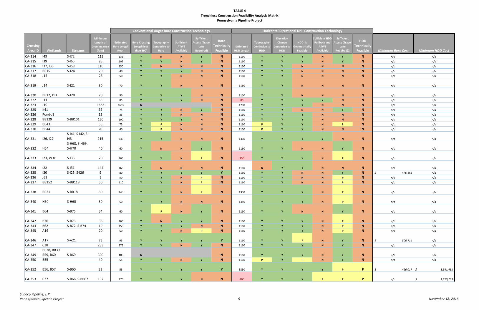
TABLE 4
Trenchless Construction Feasibility Analysis Matrix
Pennsylvania Pipeline Project
Crossing
Area ID Wetlands Streams
Minimum
Length of
Crossing Area
(feet)
Estimated
Bore Length
(feet)
Bore Crossing
Length less
than 390'
Topography
Conducive to
Bore
Sufficient
ATWS
Available
Sufficient
Access (Travel
Lane
Required)
Bore
Technically
FeasibleEstimated
HDD Length
Topography
Conducive to
HDD
Elevation
Change
Conducive to
HDD
HDD is
Geometrically
Feasible
Sufficient HDD
Pullback and
ATWS
Available
Sufficient
Access (Travel
Lane
Required)2
HDD
Technically
Feasible Minimum Bore Cost Minimum HDD Cost
Conventional Auger Bore Construction Technology Horizontal Directional Drill Construction Technology
CA-314 I43 S-I72 115 135 Y N N Y N 1160 Y Y Y N Y N n/a n/a
CA-315 I39 S-I65 85 105 Y Y N Y N 1160 Y Y Y N Y N n/a n/a
CA-316 I37, I38 S-I59 110 130 Y N N N N 1160 Y Y N N N N n/a n/a
CA-317 BB15 S-J24 20 40 Y Y Y N N 1160 Y Y N N N N n/a n/a
CA-318 J15 28 50 Y Y N N N 1160 Y Y N N N N n/a n/a
CA-319 J14 S-J21 30 70 Y Y N N N 1160 Y Y N N N N n/a n/a
CA-320 BB12, J13 S-J20 70 90 Y Y Y N N 1160 Y Y N N N N n/a n/a
CA-322 J11 65 85 Y Y Y N N 80 Y Y Y Y N N n/a n/a
CA-323 J10 1663 1695 N N 1700 Y Y Y N N N n/a n/a
CA-325 K41 52 75 Y Y N Y N 1160 Y Y N N Y N n/a n/a
CA-326 Pond-J3 12 35 Y Y N N N 1160 Y Y Y N N N n/a n/a
CA-328 BB129 S-BB101 150 190 Y Y Y N N 1160 Y Y Y N N N n/a n/a
CA-329 BB43 55 75 Y P N N N 1160 P Y Y N P N n/a n/a
CA-330 BB44 20 40 Y P N N N 1160 P Y Y N N N n/a n/a
CA-331 I26, I27
S-I41, S-I42, S-
I43 215 235 Y Y N N N 1360 Y Y Y Y N N n/a n/a
CA-332 H54
S-H68, S-H69,
S-H70 40 60 Y N N Y N 1160 Y Y N N Y N n/a n/a
CA-333 I23, W3c S-I33 20 165 Y Y N P N 750 Y Y Y N P N n/a n/a
CA-334 I22 S-I31 144 165 Y N N N N 1160 N Y Y N N N n/a n/a
CA-335 I20 S-I25, S-I26 9 80 Y Y Y Y Y 1160 Y Y N N Y N 476,453$ n/a
CA-336 J63 5 50 Y Y N P N 1160 Y Y N N P N n/a n/a
CA-337 BB152 S-BB118 50 110 Y Y N P N 1160 Y Y N N P N n/a n/a
CA-338 BB21 S-BB18 80 140 Y Y N P N 1350 Y Y Y N P N n/a n/a
CA-340 H50 S-H60 30 50 Y Y N N N 1350 Y Y Y N P N n/a n/a
CA-341 B64 S-B75 34 60 Y P N Y N 1160 Y Y N N Y N n/a n/a
CA-342 B76 S-B73 36 165 Y N Y Y N 1160 Y Y Y N P N n/a n/a
CA-343 B62 S-B72, S-B74 19 150 Y Y Y N N 1160 Y Y Y N P N n/a n/a
CA-345 A16 20 50 Y Y N P N 1160 Y Y Y N P N n/a n/a
CA-346 A17 S-A21 75 95 Y Y Y Y Y 1160 Y Y P N Y N 506,714$ n/a
CA-347 C28 233 275 Y Y N Y N 1160 Y Y Y N Y N n/a n/a
CA-349
BB38, BB39,
B59, B60 S-B69 390 400 N N 1160 Y Y Y N Y N n/a n/a
CA-350 B55 40 55 Y Y N Y N 1160 P Y P N Y N n/a n/a
CA-352 B56, B57 S-B60 33 55 Y Y Y Y Y 3850 Y Y Y Y P P 426,017$ 8,541,431$
CA-353 C27 S-B66, S-BB67 132 175 Y Y Y N N 700 Y Y Y P P P n/a 1,810,763$
Sunoco Pipeline, L.P.
Pennsylvania Pipeline Project 9 November 18, 2016
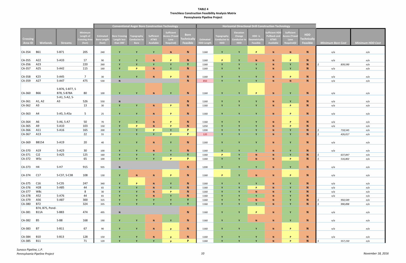
TABLE 4
Trenchless Construction Feasibility Analysis Matrix
Pennsylvania Pipeline Project
Crossing
Area ID Wetlands Streams
Minimum
Length of
Crossing Area
(feet)
Estimated
Bore Length
(feet)
Bore Crossing
Length less
than 390'
Topography
Conducive to
Bore
Sufficient
ATWS
Available
Sufficient
Access (Travel
Lane
Required)
Bore
Technically
FeasibleEstimated
HDD Length
Topography
Conducive to
HDD
Elevation
Change
Conducive to
HDD
HDD is
Geometrically
Feasible
Sufficient HDD
Pullback and
ATWS
Available
Sufficient
Access (Travel
Lane
Required)2
HDD
Technically
Feasible Minimum Bore Cost Minimum HDD Cost
Conventional Auger Bore Construction Technology Horizontal Directional Drill Construction Technology
CA-354 B61 S-B71 205 240 Y Y Y N N 1160 Y Y P N N N n/a n/a
CA-355 A22 S-A33 17 90 Y Y N P N 1160 P Y N N P N n/a n/a
CA-356 A23 220 260 Y Y Y Y Y 1160 Y Y Y N Y N 839,590$ n/a
CA-357 A25 S-A42 115 160 Y P N Y N 1160 Y Y Y N Y N n/a n/a
CA-358 K23 S-A45 7 30 Y Y N P N 1160 Y Y Y N P N n/a n/a
CA-359 A27 S-A47 475 530 N N 850 Y Y Y N N N n/a n/a
CA-360 B66
S-B76, S-B77, S-
B78, S-B78A 80 100 Y Y N Y N 1160 Y Y P N Y N n/a n/a
CA-361 A1, A2
S-A1, S-A2, S-
A3 526 550 N N 1160 Y Y Y N Y N n/a n/a
CA-362 A3 13 30 Y Y N P N 1160 Y Y Y N P N n/a n/a
CA-363 A4 S-A5, S-A5a 5 25 Y Y N P N 1160 Y Y Y N P N n/a n/a
CA-364 A6 S-A6, S-A7 50 70 Y Y N P N 1160 Y Y Y N P N n/a n/a
CA-365 A9 S-A10 103 150 Y P N P N 1250 Y Y Y N P N n/a n/a
CA-366 A11 S-A16 165 200 Y Y P Y P 1200 Y Y Y N Y N 718,545$ n/a
CA-367 A13 22 55 Y Y Y P P 120 Y Y Y N Y N 426,017$ n/a
CA-369 BB154 S-A19 20 40 Y Y N Y N 1160 Y Y Y N Y N n/a n/a
CA-370 A19 S-A23 30 100 Y Y N Y N 1160 Y Y Y N Y N n/a n/a
CA-371 CJ2 S-A25 125 160 Y Y Y Y Y 1160 P Y N N Y N 637,847$ n/a
CA-372 W5c 65 100 Y Y Y P P 1160 Y Y N N P N 516,802$ n/a
CA-373 H4 S-H7 915 935 N N 1200 Y Y Y N Y N n/a n/a
CA-374 C17 S-C37, S-C38 108 130 Y N N P N 1160 P Y N N P N n/a n/a
CA-375 C16 S-C35 247 340 Y P N Y N 1160 Y Y Y N Y N n/a n/a
CA-376 H28 S-A85 44 65 Y Y N Y N 1160 Y Y P N Y N n/a n/a
CA-377 W8c 8 30 Y Y N P N 1160 Y Y N N Y N n/a n/a
CA-378 A52 S-A76 44 65 Y Y N Y N 1160 Y Y Y N Y N n/a n/a
CA-379 A56 S-A87 300 315 Y Y Y Y Y 1160 Y Y N N Y N 950,549$ n/a
CA-380 B72 324 335 Y Y Y Y Y 1160 Y Y Y N Y N 990,898$ n/a
CA-381
B74, B75, Pond-
B11A S-B83 474 495 N N 1160 Y Y P N Y N n/a n/a
CA-382 B5 S-B8 168 190 Y Y N Y N 1160 Y Y N N Y N n/a n/a
CA-383 B7 S-B11 67 90 Y Y N p N 1160 Y Y Y N P N n/a n/a
CA-384 B10 S-B13 128 150 Y Y N p N 1160 Y Y Y N P N n/a n/a
CA-385 B11 71 120 Y Y Y p P 1160 Y Y Y N P N 557,150$ n/a
Sunoco Pipeline, L.P.
Pennsylvania Pipeline Project 10 November 18, 2016

TABLE 4
Trenchless Construction Feasibility Analysis Matrix
Pennsylvania Pipeline Project
Crossing
Area ID Wetlands Streams
Minimum
Length of
Crossing Area
(feet)
Estimated
Bore Length
(feet)
Bore Crossing
Length less
than 390'
Topography
Conducive to
Bore
Sufficient
ATWS
Available
Sufficient
Access (Travel
Lane
Required)
Bore
Technically
FeasibleEstimated
HDD Length
Topography
Conducive to
HDD
Elevation
Change
Conducive to
HDD
HDD is
Geometrically
Feasible
Sufficient HDD
Pullback and
ATWS
Available
Sufficient
Access (Travel
Lane
Required)2
HDD
Technically
Feasible Minimum Bore Cost Minimum HDD Cost
Conventional Auger Bore Construction Technology Horizontal Directional Drill Construction Technology
CA-386 B16, B17, B18 S-B16 70 150 Y Y N N N 1160 P Y N N Y N n/a n/a
CA-387 A49 S-A73 78 100 Y Y N Y N 1160 Y Y N N Y N n/a n/a
CA-388 B21, B22
S-B22, S-B23, S-
B24 446 470 N N 1160 Y Y Y N Y N n/a n/a
CA-389 B24 S-B25 78 100 Y Y N p N 1600 Y Y Y N Y N n/a n/a
CA-390 K25 24 95 Y Y N p N 1600 Y Y Y N Y N n/a n/a
CA-391 B42 S-B47 65 95 Y Y N p N 1600 Y Y Y N P N n/a n/a
CA-392 B43 S-B48 84 105 Y N N Y N 1160 P Y Y N Y N n/a n/a
CA-393 B44 S-B49 50 80 Y Y N Y N 1800 Y Y Y N Y N n/a n/a
CA-394 B48 37 160 Y Y Y Y Y 1800 Y Y Y N Y N 637,847$ n/a
CA-395 B49 S-B50 25 135 Y Y Y Y Y 1160 Y Y N N Y N 587,412$ n/a
CA-396 B40 40 60 Y Y N Y N 1160 Y Y N N Y N n/a n/a
CA-398 C12 S-C31 122 195 Y Y Y Y Y 1160 Y Y Y N Y N 708,457$ n/a
CA-399 W48PEM-2 S-BB34. S-B33 8 30 Y Y N p N 1160 Y Y Y N P N n/a n/a
CA-400 AM2 S-C11 207 230 Y Y N Y N 1160 Y Y N N N N n/a n/a
CA-401 C1 S-C1 116 190 Y Y N Y N 1160 Y Y Y N P N n/a n/a
CA-402 C2 S-C2 28 50 Y Y N p N 1160 Y Y Y N P N n/a n/a
CA-403 C5 S-C7 70 90 Y p N Y N 1160 Y Y Y N Y N n/a n/a
CA-404 B32, B33 S-B30 247 395 N N 1160 Y Y Y N P N n/a n/a
CA-405
B27, B28, B29,
B30, B31,
W302 S-B29 830 850 N N 1400 Y Y Y N N N n/a n/a
CA-406 H24, H25, H26 S-H22, S-H23 220 320 Y Y N p N 1160 Y Y Y N P N n/a n/a
CA-407 H23 50 70 Y Y N p N 1160 Y Y Y N P N n/a n/a
CA-408 W301 S-H13, S-H15 85 105 Y Y N p N 1160 P Y N N P N n/a n/a
CA-409 H21 S-H16 30 70 Y Y N p N 1160 Y Y Y N P N n/a n/a
CA-410 W35 S-Q62 330 450 N N 1160 Y Y Y N Y N n/a n/a
CA-411 BA10 85 105 Y Y Y p P 120 Y Y Y Y Y Y 526,889$ 571,465$
CA-412 A45 93 250 Y Y N Y N 1160 Y Y Y N Y N n/a n/a
CA-413 A46 16 40 Y Y Y P P 1160 Y Y Y N P N 395,756$ n/a
Sunoco Pipeline, L.P.
Pennsylvania Pipeline Project 11 November 18, 2016
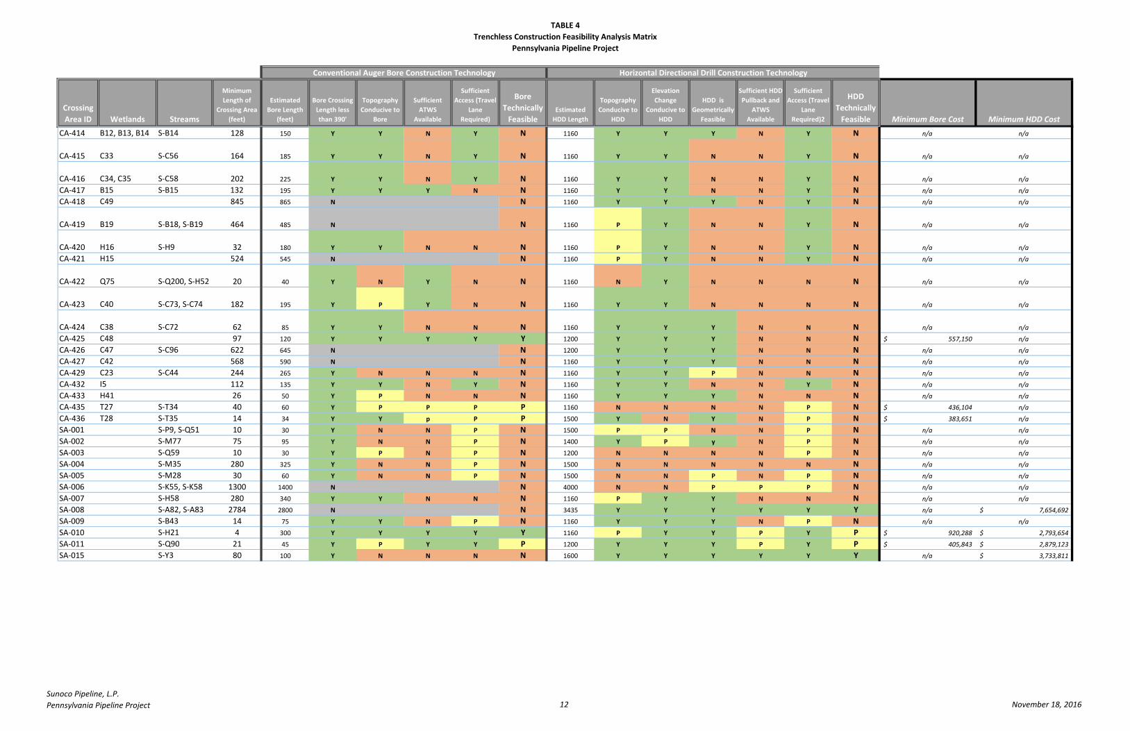
TABLE 4
Trenchless Construction Feasibility Analysis Matrix
Pennsylvania Pipeline Project
Crossing
Area ID Wetlands Streams
Minimum
Length of
Crossing Area
(feet)
Estimated
Bore Length
(feet)
Bore Crossing
Length less
than 390'
Topography
Conducive to
Bore
Sufficient
ATWS
Available
Sufficient
Access (Travel
Lane
Required)
Bore
Technically
FeasibleEstimated
HDD Length
Topography
Conducive to
HDD
Elevation
Change
Conducive to
HDD
HDD is
Geometrically
Feasible
Sufficient HDD
Pullback and
ATWS
Available
Sufficient
Access (Travel
Lane
Required)2
HDD
Technically
Feasible Minimum Bore Cost Minimum HDD Cost
Conventional Auger Bore Construction Technology Horizontal Directional Drill Construction Technology
CA-414 B12, B13, B14 S-B14 128 150 Y Y N Y N 1160 Y Y Y N Y N n/a n/a
CA-415 C33 S-C56 164 185 Y Y N Y N 1160 Y Y N N Y N n/a n/a
CA-416 C34, C35 S-C58 202 225 Y Y N Y N 1160 Y Y N N Y N n/a n/a
CA-417 B15 S-B15 132 195 Y Y Y N N 1160 Y Y N N Y N n/a n/a
CA-418 C49 845 865 N N 1160 Y Y Y N Y N n/a n/a
CA-419 B19 S-B18, S-B19 464 485 N N 1160 P Y N N Y N n/a n/a
CA-420 H16 S-H9 32 180 Y Y N N N 1160 P Y N N Y N n/a n/a
CA-421 H15 524 545 N N 1160 P Y N N Y N n/a n/a
CA-422 Q75 S-Q200, S-H52 20 40 Y N Y N N 1160 N Y N N N N n/a n/a
CA-423 C40 S-C73, S-C74 182 195 Y P Y N N 1160 Y Y N N N N n/a n/a
CA-424 C38 S-C72 62 85 Y Y N N N 1160 Y Y Y N N N n/a n/a
CA-425 C48 97 120 Y Y Y Y Y 1200 Y Y Y N N N 557,150$ n/a
CA-426 C47 S-C96 622 645 N N 1200 Y Y Y N N N n/a n/a
CA-427 C42 568 590 N N 1160 Y Y Y N N N n/a n/a
CA-429 C23 S-C44 244 265 Y N N N N 1160 Y Y P N N N n/a n/a
CA-432 I5 112 135 Y Y N Y N 1160 Y Y N N Y N n/a n/a
CA-433 H41 26 50 Y P N N N 1160 Y Y Y N N N n/a n/a
CA-435 T27 S-T34 40 60 Y P P P P 1160 N N N N P N 436,104$ n/a
CA-436 T28 S-T35 14 34 Y Y p P P 1500 Y N Y N P N 383,651$ n/a
SA-001 S-P9, S-Q51 10 30 Y N N P N 1500 P P N N P N n/a n/a
SA-002 S-M77 75 95 Y N N P N 1400 Y P y N P N n/a n/a
SA-003 S-Q59 10 30 Y P N P N 1200 N N N N P N n/a n/a
SA-004 S-M35 280 325 Y N N P N 1500 N N N N N N n/a n/a
SA-005 S-M28 30 60 Y N N P N 1500 N N P N P N n/a n/a
SA-006 S-K55, S-K58 1300 1400 N N 4000 N N P P P N n/a n/a
SA-007 S-H58 280 340 Y Y N N N 1160 P Y Y N N N n/a n/a
SA-008 S-A82, S-A83 2784 2800 N N 3435 Y Y Y Y Y Y n/a 7,654,692$
SA-009 S-B43 14 75 Y Y N P N 1160 Y Y Y N P N n/a n/a
SA-010 S-H21 4 300 Y Y Y Y Y 1160 P Y Y P Y P 920,288$ 2,793,654$
SA-011 S-Q90 21 45 Y P Y Y P 1200 Y Y Y P Y P 405,843$ 2,879,123$
SA-015 S-Y3 80 100 Y N N N N 1600 Y Y Y Y Y Y n/a 3,733,811$
Sunoco Pipeline, L.P.
Pennsylvania Pipeline Project 12 November 18, 2016