traverseedge 2020 system documentation hardware ... · traverseedge 2020 system documentation ......
TRANSCRIPT
Turin Networks Inc.
TraverseEdge 2020 System
Documentation
Software Release 5.0.xPublication Date: April 2007
Document Number: 800-0017-50 Rev. A
Hardware Description Guide

Copyright © 2007 Turin Networks, Inc.
All rights reserved. This document contains proprietary and confidential information of Turin Networks, Inc., and may not be used, reproduced, or distributed except as authorized by Turin Networks. No part of this publication may be reproduced in any form or by any means or used to make any derivative work (such as translation, transformation or adaptation) without written permission from Turin Networks, Inc.
Turin Networks reserves the right to revise this publication and to make changes in content from time to time without obligation on the part of Turin Networks to provide notification of such revision or change. Turin Networks may make improvements or changes in the product(s) described in this manual at any time.
Turin Networks Trademarks
Turin Networks, the Turin Networks logo, Traverse, TraverseEdge, Traverse PacketEdge, TransAccess, TransNav, Traverse PacketEdge, TPE-1200, TE-2020, TE-206, TN-Xpert, TN-Xsight, TN-Xconnect, TN-Xtend, TN-Xrelay, and Creating The Broadband Edge are trademarks of Turin Networks, Inc. or its affiliates in the United States and other countries. All other trademarks, service marks, product names, or brand names mentioned in this document are the property of their respective owners. Inquiries concerning such products, services, or marks should be made directly to those companies.
Product Use
The TraverseEdge 2020 is part of a family of products designed and manufactured by Turin Networks for the telecommunications industry.
Government Use
Use, duplication, or disclosure by the U.S. Government is subject to restrictions as set forth in FAR 12.212 (Commercial Computer Software-Restricted Rights) and DFAR 227.7202 (Rights in Technical Data and Computer Software), as applicable.

Release 5.0.x Turin Networks Page iii
PREFACE
Revision History The following lists the sections of this document affected by any informational changes:
Section Issue Date Reason For Change
All 01 4/2007 First Release 5.0 Version (Preliminary)
Related Documents The following documents pertain to Turin’s TraverseEdge 2020 (TE-2020) optical transport equipment. For online documentation, visit Turin’s website and register for access to the web portal at www.force10networks.com.
Table 1 TE-2020™ Document List
Document Title Description
TE-2020 Ordering Manual Provides a brief description of each module available for the TE-2020 system, part num-bers, compatibility information, and the contact information required to order them.
TE-2020 Users Manual Provides information vital for proper operation and maintenance of Turin Networks TE-2020 system. Information provided deals with processes and procedures for turn-up, test, maintenance duties, input command sequences, valid parameters, and expected responses in TL-1 and TN-Sight.
TE-2020 Applications Engineering Manual
Provides information vital for the proper deployment of a Turin Networks TE-2020 sys-tem. Information provided deals with environmental requirements, specifications, and applications.
TE-2020 Hardware Installa-tion Manual
Provides information vital for proper installation of Turin Networks TE-2020 equipment. Information provided deals with site layout, required hardware, power connections, cable connections, and interfaces that must be hardwired.
TE-2020 TL-1 Reference Man-ual
Provides information vital for proper communication with Turin Networks TE-2020 sys-tem. Information provided deals with all TL-1 command structures, valid parameters, and expected responses, and error codes.
TE-2020 Hardware Descrip-tion Manual
Provides detailed information for each card, shelf and accessory for a Turin Networks TE-2020 system. Information provided includes card level diagrams, operational require-ments, specifications, and applications.
Table 2 TN-Xpert™ Document List
Document Title Description
TN-Xpert Installation Manual Provides information required to properly install and maintain TN-Xpert Client and Server for both Solaris and Windows Environments. Information provided deals with Operation System configuration, database installation, user account configuration, TN-Xpert software installation and Network Element IP connectivity

Page iv Turin Networks Release 5.0.x
PrecautionsThroughout this document, there are important precautionary statements used to warn of possible hazards to persons or equipment. A precaution identifies a possible hazard and then explains what may happen if the hazard is not avoided. The Danger, Warning, and Caution statements should be followed at all times to ensure safe and proper installation, operation, and reliability of the prod-uct. When multiple precautions are present, they are listed in order of severity as follows:
Danger! Indicates that a certain risk is associated with the task that will cause severe per-sonal injury, death, or substantial property damage if the procedure is not adhered to as written.
Warning! Indicates that a certain risk is associated with the task that can cause personal injury, death, or substantial property damage if the procedure is not adhered to as written.
Caution! Indicates that a certain risk is associated with the task that can or will cause per-sonal injury or property damage if the procedure is not adhered to as written.
General Safety PrecautionsThese precautions will be found throughout the document whenever the optical cards or other sys-tem components are being discussed.
Danger! Never look into the end of an optical fiber. Exposure to invisible LASER radiation can cause serious and/or permanent damage to the eye or even blindness. Verify the optical source is disabled through the use of an optical power meter before handling optical fibers. Use of controls, adjustments, or procedures other than those specified within this document may result in hazardous laser radiation expo-sure.
Caution! Electrostatic Discharge (ESD) sensitive devices. ESD can cause catastrophic fail-ure or degraded life and performance of a device. Use an anti-static wrist strap connected to a properly grounded source before contacting any electronic devices.
Standards ComplianceNEBS Level 3 per SR-3580 (ref. GR-63 & GR-1089)
UL 60950, 3rd Edition
CDRH Laser Certification
FCC Part 15 Class B
ANSI Z136.1 - 1993 - American National Standard for the Safe Use of Lasers
TN-Xpert Users Manual Provides information vital for proper operation and maintenance of Turin Networks TE-2020 and TE-206 systems. Information provided deals with processes and procedures for turn-up, test, maintenance duties, input command sequences, valid parameters, and expected responses using TN-Xpert™.
Table 2 TN-Xpert™ Document List
Document Title Description

Release 5.0.x Turin Networks Page v
FCC WarningThe TE-2020 system has been tested and found to comply with the limits for a Class A digital device, pursuant to Part 15 of the FCC Rules. These limits are designed to provide reasonable protection against harmful interference when this equipment is operated in a commercial environ-ment. This equipment generates, uses, and can radiate radio frequency energy and, if not installed and used in accordance with the instructions, may cause harmful interference to radio and televi-sion communications. Operation of this equipment in a residential area is likely to cause interfer-ence, in which case the user will be required to correct the interference at his or her own expense. Shielded cables must be used with this unit to ensure compliance with the Class A FCC limits.
Contact InformationThis section contains the addresses and phone numbers of Turin Networks offices. For sales and technical assistance, go to www.force10networks.com
Query and Contact Information Matrix
Query Contact Group
Contact Information
• Warranty Issues
• Part Issues
• Repair Service
• Upgrades
• Installation and Test
• Training
Technical Assistance Center (TAC)
Inside the U.S., toll-free 1-866-887-4638Outside the U.S. 707-665-4355Online www.force10networks.com\supportE-mail [email protected]

Page vi Turin Networks Release 5.0.x
If You Need AssistanceIf you need assistance while working with the TE-2020 product, contact the Technical Assistance Center (TAC). TAC is available 24 hours a day, 7 days a week. E-mail support is available through: [email protected].
Calling for RepairsIf repair is necessary, call TAC at 1-866-877-4638 for a Return Material Authorization (RMA) number before sending the unit. The RMA number must be prominently displayed on all equipment cartons. When calling outside the United States, use the appropriate international access code, and then call 707-665-4355 to contact TAC. When shipping equipment for repair, follow these steps:1. Pack the unit securely.
2. Enclose a note describing the exact problem.
3. Enclose a copy of the invoice that verifies the warranty status.
4. Ship the unit PREPAID to the following address:
Force10 Networks, Inc.Attn: RMA # ________700 N. Glenville Dr.Richardson, TX 75081 USA
AcronymsACO Alarm Cut-offADM Add/Drop MultiplexerBITS Building Integrated Timing SupplyBLSR Bi-directional Line Switched RingCCT Common Control and TimingCDRH Center for Devices and Radiological HealthCLI Command Line InterfaceCO Central OfficeD&C Drop and ContiunueDCC Data Communications ChannelDS3 Digital Signal Level 3 at 45 MbpsDWDM Dense Wave Division MultiplexingEC1 Electrical Carrier Level 1EMS Element Management SystemEoS Ethernet Over SONETFCC Federal Communications CommissionFTP File Transfer Protocol

Release 5.0.x Turin Networks Page vii
GbE Giga-bit EthernetGFP Generic Framing ProcedureGMPLS Generalized Multi-Protocol Label Switching GNE Gateway Network ElementGUI Graphical User InterfaceHTTP Hyper-text Transfer ProtocolIR Intermediate ReachLAN Local Area NetworkLDCC Line Data Communications ChannelLDF Lightwave Distribution FrameLEI Local Equipment InterconnectLR Long ReachLSP Label Switched PathLTE Line Terminating EquipmentMAC Media Access ControlMMF Multi-mode FiberNEBS Network Equipment - Building SystemsNE Network ElementNTP Network Time ProtocolNUT Non-Preemptable Unprotected TrafficO-ADM Optical Add Drop MultiplexerOAM&P Operations, Administration, Maintenance and ProvisioningOC Optical CarrierOC-12 Optical Carrier Level 12 at 622 MbpsOC-192 Optical Carrier Level 192 at 9.6 GbpsOC-3 Optical Carrier Level 3 at 155 MbpsOC-48 Optical Carrier Level 48 at 2.4 GbpsOS Operating SystemOSPF Open Shortest Path FirstOSS Operation Support SystemPCA Protected Channel AccessPLM Physical Layer ModulePOH Path OverheadRST ResetRU Rack Unit (1 RU = 1.75”)RX ReceiveSONET Synchronous Optical NetworkSLA Service Level AgreementSMF Single Mode FiberSR Short ReachSTAT StatusSTS Concatenated Synchronous Transport SignalSTS-1c Concatenated Synchronous Transport Signal Level 1 at 52 MbpsSTS-12c Concatenated Synchronous Transport Signal Level 12 at 622 MbpsSTS-3c Concatenated Synchronous Transport Signal Level 3 at 155 MbpsSTS-48c Concatenated Synchronous Transport Signal Level 48 at 2.4 GbpsTBD To Be Determined

Page viii Turin Networks Release 5.0.x
TCP/IP Transport Control Protocol/Internet ProtocolTID Target IdentifierTL-1 Transaction Language Level 1TX TransmitUL Underwriters LaboratoriesUPSR Unidirectional Path Switched RingVC Virtual ConcatenationVdc Voltage - Direct CurrentVLAN Virtual LanVPN Virtual Private NetworkVR Very Long ReachWDM Wave Division Multiplexing
TraverseEdge 2020 Hardware Description Guide
Release 5.0.x Turin Networks Page ix
Table of Contents
Item Page
Chapter 1 Introduction ............................................................................................................................................ 1-11.1 TE-2020 Main Shelf ......................................................................................................................1-11.2 OTS2 ............................................................................................................................................1-21.3 DS3/EC1 Tributary Shelf ...........................................................................................................1-31.4 ETS2 Shelf ...................................................................................................................................1-31.5 Physical Layer Modules .............................................................................................................1-31.6 Cables and Miscellaneous ..........................................................................................................1-41.7 TE-206 .......................................................................................................................................................... 1-4
Chapter 2 TE-2020 Main Shelf ................................................................................................................................ 2-12.1 TE-2020 Main Shelf - 19” ............................................................................................................................. 2-1
2.2 TE-2020 Main Shelf - 23” ............................................................................................................................. 2-3
2.3 Power Supply and Return ............................................................................................................................ 2-5
2.4 Frame Ground .............................................................................................................................................. 2-5
2.5 Backplane ..................................................................................................................................................... 2-5
2.6 LEI Connectors ............................................................................................................................................. 2-5
2.7 Wire-Wrap Pin Field ..................................................................................................................................... 2-6
2.8 Front RJ-45 Craft User Port ....................................................................................................................... 2-13
2.9 Rear RJ-45 Ethernet Ports ......................................................................................................................... 2-14
2.10 Rear Serial Communications Port ............................................................................................................ 2-15
2.11 Front Cover ............................................................................................................................................... 2-16
Chapter 3 TE-2020 Main CCT .................................................................................................................................. 3-13.1 Configurations .............................................................................................................................................. 3-1
3.2 Physical Specifications ................................................................................................................................. 3-1
3.3 Functional Description .................................................................................................................................. 3-2
3.4 Control of the Shelf ....................................................................................................................................... 3-2
3.5 1920 x 1920 STS-1 Cross-connect .............................................................................................................. 3-4
3.6 LEI Termination and Protection .................................................................................................................... 3-4
3.7 Connectivity .................................................................................................................................................. 3-4
Chapter 4 TE-2020 Main Fan Tray .......................................................................................................................... 4-14.1 Functional Description .................................................................................................................................. 4-1
Chapter 5 OTS2 Shelf .............................................................................................................................................. 5-15.1 OTS2 - 19” .................................................................................................................................................... 5-1
5.2 OTS2 - 23” .................................................................................................................................................... 5-3
5.3 Power Supply and Return ............................................................................................................................ 5-5
5.4 Frame Ground .............................................................................................................................................. 5-5
5.5 Backplane ..................................................................................................................................................... 5-5
5.6 LEI Connectors ............................................................................................................................................. 5-5
5.7 Front Cover .................................................................................................................................................. 5-6
Chapter 6 OTS2 CCT ............................................................................................................................................... 6-16.1 Configurations .............................................................................................................................................. 6-1
6.2 Physical Specifications ................................................................................................................................. 6-1
6.3 Functional Description .................................................................................................................................. 6-2
6.4 SONET/SDH Mapping .................................................................................................................................. 6-4
6.5 Local Hairpinning .......................................................................................................................................... 6-4
6.6 Local Equipment Interconnect (LEI) ............................................................................................................. 6-4
6.7 Connectivity .................................................................................................................................................. 6-4
Chapter 7 OTS2 Fan Tray ........................................................................................................................................ 7-1

TraverseEdge 2020 Hardware Description Guide
Page x Turin Networks Release 5.0.x
7.1 Functional Description .................................................................................................................................. 7-1
Chapter 8 DS3/EC1 Tributary Shelf(ETS1) ....................................................................................................................................................................... 8-1
8.1 DS3/EC1 Tributary Shelf (ETS1) - 19" ......................................................................................................... 8-1
8.2 DS3/EC1 Tributary Shelf (ETS1) - 23" ......................................................................................................... 8-3
8.3 Power Supply and Return ............................................................................................................................ 8-5
8.4 Frame Ground .............................................................................................................................................. 8-6
8.5 Backplane ..................................................................................................................................................... 8-6
8.6 LEI Connection ............................................................................................................................................. 8-6
8.7 1:n Protection ............................................................................................................................................... 8-7
8.8 Front Cover .................................................................................................................................................. 8-7
Chapter 9 DS3/EC1 Tributary (ETS1) CCT ............................................................................................................. 9-19.1 Configurations .............................................................................................................................................. 9-1
9.2 Physical Specifications ................................................................................................................................. 9-1
9.3 Functional Description .................................................................................................................................. 9-2
9.4 SONET Mapping .......................................................................................................................................... 9-3
9.5 Local Equipment Interconnect (LEI) ............................................................................................................. 9-3
9.6 Backplane Connectors ................................................................................................................................. 9-3
Chapter 10 ETS Fan Tray ...................................................................................................................................... 10-110.1 Functional Description .............................................................................................................................. 10-2
10.2 Front Panel ............................................................................................................................................... 10-2
10.3 3 RU Fan Filter ........................................................................................................................................ 10-4
Chapter 11 ETS2 Shelf .......................................................................................................................................... 11-111.1 ETS2 - 19" ................................................................................................................................................ 11-1
11.2 ETS2 - 23" ................................................................................................................................................ 11-3
11.3 Power Supply and Return ....................................................................................................................... 11-10
11.4 Frame Ground .........................................................................................................................................11-11
11.5 Backplane ................................................................................................................................................11-11
11.6 LEI Connection ........................................................................................................................................11-11
11.7 Protection ............................................................................................................................................... 11-12
11.8 Front Cover ............................................................................................................................................. 11-12
Chapter 12 ETS2 CCT ............................................................................................................................................ 12-112.1 Configurations .......................................................................................................................................... 12-1
12.2 Physical Specifications ............................................................................................................................. 12-1
12.3 Functional Description .............................................................................................................................. 12-2
12.4 SONET Mapping ...................................................................................................................................... 12-3
12.5 Local Equipment Interconnect (LEI) ......................................................................................................... 12-3
12.6 Backplane Connectors ............................................................................................................................. 12-3
Chapter 13 OC-192 Physical Layer .......................................................................................................Modules 13-113.1 Configurations .......................................................................................................................................... 13-1
13.2 Physical Specifications ............................................................................................................................. 13-2
13.3 Optical Parameters ................................................................................................................................... 13-3
13.4 Connectorization ...................................................................................................................................... 13-7
13.5 LED Indicators .......................................................................................................................................... 13-8
Chapter 14 OC-48 Physical Layer Modules ......................................................................................................... 14-114.1 Configurations .......................................................................................................................................... 14-3
14.2 Physical Specifications ............................................................................................................................. 14-3
14.3 Optical Parameters ................................................................................................................................ 14-14
14.4 Connectorization .................................................................................................................................... 14-17
14.5 LED Indicators ........................................................................................................................................ 14-20
TraverseEdge 2020 Hardware Description Guide
Release 5.0.x Turin Networks Page xi
14.6 CCT Connectors ..................................................................................................................................... 14-21
Chapter 15 OC-12 Physical Layer Modules ......................................................................................................... 15-115.1 OC-12 x2 PLM .......................................................................................................................................... 15-1
15.2 OC-12 x4 PLM .......................................................................................................................................... 15-6
Chapter 16 OC-3 Physical Layer Modules .................................................................................................................................................................. 16-1
16.1 Configurations .......................................................................................................................................... 16-1
16.2 Physical Specifications ............................................................................................................................. 16-2
16.3 Optical Parameters ................................................................................................................................... 16-3
16.4 Functional Description .............................................................................................................................. 16-5
16.5 Connectorization ...................................................................................................................................... 16-5
16.6 LED Indicators .......................................................................................................................................... 16-6
16.7 CCT Connectors ....................................................................................................................................... 16-7
Chapter 17 GbE Physical Layer Modules .................................................................................................................................................................. 17-1
17.1 Configurations .......................................................................................................................................... 17-1
17.2 Physical Specifications ............................................................................................................................. 17-2
17.3 Optical Parameters ................................................................................................................................... 17-4
17.4 Functional Description .............................................................................................................................. 17-6
17.5 Connectorization ...................................................................................................................................... 17-6
17.6 LED Indicators .......................................................................................................................................... 17-7
17.7 CCT Connectors ....................................................................................................................................... 17-8
17.8 VLAN Capability ....................................................................................................................................... 17-8
Chapter 18 DS3/EC1 Physical Layer Modules .................................................................................................... 18-118.1 Configurations .......................................................................................................................................... 18-2
18.2 Physical Specifications ............................................................................................................................. 18-2
18.3 Electrical Parameters ............................................................................................................................... 18-2
18.4 LED Indicators .......................................................................................................................................... 18-3
18.5 Connectorization ...................................................................................................................................... 18-4
18.6 Test Access .............................................................................................................................................. 18-4
18.7 SONET Framing and Mapping ................................................................................................................. 18-5
18.8 DS3 TMUX ............................................................................................................................................... 18-6
Chapter 19 DS1 Physical Layer Modules .................................................................................................................................................................. 19-1
19.1 Configurations .......................................................................................................................................... 19-1
19.2 Physical Specifications ............................................................................................................................. 19-2
19.3 Electrical Parameters ............................................................................................................................... 19-2
19.4 LED Indicators .......................................................................................................................................... 19-3
19.5 Connectorization ...................................................................................................................................... 19-4
19.6 Test Access .............................................................................................................................................. 19-4
Chapter 20 FastE Physical Layer Module .................................................................................................................................................................... 20-1
20.1 Configurations .......................................................................................................................................... 20-1
20.2 Physical Specifications ............................................................................................................................. 20-2
20.3 Electrical Parameters ............................................................................................................................... 20-3
20.4 LED Indicators .......................................................................................................................................... 20-3
20.5 Connectorization ...................................................................................................................................... 20-4
Chapter 21 Local Equipment Interconnect Cables .............................................................................................................................................. 21-1
21.1 Features ................................................................................................................................................... 21-1
21.2 Functional Description .............................................................................................................................. 21-2

TraverseEdge 2020 Hardware Description Guide
Page xii Turin Networks Release 5.0.x
21.3 LEI Cabling Examples .............................................................................................................................. 21-2
Chapter 22 Interface Cables ................................................................................................................................. 22-122.1 User Interface Cables ............................................................................................................................... 22-1
22.2 DS1 Interface Cables ............................................................................................................................... 22-4
22.3 DS3 Interface Cables ............................................................................................................................... 22-5
22.4 FastE Patch Panel Interconnect Cable .................................................................................................... 22-7
22.5 LEI Interfaces ........................................................................................................................................... 22-8

TraverseEdge 2020 Hardware Description Guide
Release 5.0.x Turin Networks Page xiii
List of Figures
Item Page
Chapter 1 IntroductionFigure 1-1 TE-2020 Main Shelf........................................................................................................................... 1-2
Figure 1-2 OTS2 Shelf ........................................................................................................................................ 1-2
Figure 1-3 DS3/EC1 Tributary Shelf (ETS1)....................................................................................................... 1-3
Figure 1-4 ETS2 Shelf ........................................................................................................................................ 1-3
Chapter 2 TE-2020 Main ShelfFigure 2-1 TE-2020 Main Shelf - 19” Features ................................................................................................... 2-2
Figure 2-2 TE-2020 Main Shelf - 19” Backplane ................................................................................................ 2-2
Figure 2-3 TE-2020 Main Shelf - 19” Air Flow .................................................................................................... 2-3
Figure 2-4 TE-2020 Main Shelf - 23” Features ................................................................................................... 2-4
Figure 2-5 TE-2020 Main Shelf - 23” Air Flow .................................................................................................... 2-4
Figure 2-6 A and B Power Connectors ............................................................................................................... 2-5
Figure 2-7 Wire-Wrap Pin Field .......................................................................................................................... 2-6
Figure 2-8 Environmental Input Pins .................................................................................................................. 2-8
Figure 2-9 External Output Control Pins............................................................................................................. 2-9
Figure 2-10 Audible and Visible Alarm Control Pins........................................................................................... 2-10
Figure 2-11 Alarm Cut-Off Control Pins.............................................................................................................. 2-11
Figure 2-12 BITS Input/Derived Output Control Pins.......................................................................................... 2-12
Figure 2-13 User Port and Cable....................................................................................................................... 2-13
Figure 2-14 Front ETH-F User Interface Cable ................................................................................................ 2-14
Figure 2-15 Rear RJ-45 ports ............................................................................................................................. 2-14
Figure 2-16 Rear Serial Interface Port ................................................................................................................ 2-15
Figure 2-17 TE-2020 Main Shelf Front Cover..................................................................................................... 2-16
Chapter 3 TE-2020 Main CCTFigure 3-1 TE-2020 Main CCT ........................................................................................................................... 3-1
Figure 3-2 TE-2020 Main CCT Front View ......................................................................................................... 3-3
Chapter 4 TE-2020 Main Fan TrayFigure 4-1 TE-2020 Main Fan Tray .................................................................................................................... 4-1
Figure 4-2 TE-2020 Main Fan Tray Front Panel ................................................................................................. 4-2
Figure 4-3 23” Extension Air Filter ...................................................................................................................... 4-3
Figure 4-4 User Interface Wiring Scheme .......................................................................................................... 4-4
Figure 4-5 2 RU Fan Filter .................................................................................................................................. 4-5
Figure 4-6 Shelf with Chassis Filter .................................................................................................................... 4-6
Figure 4-7 2 RU Chassis Filter ........................................................................................................................... 4-6
Chapter 5 OTS2 ShelfFigure 5-1 OTS2 - 19” Features ......................................................................................................................... 5-2
Figure 5-2 OTS2 - 19” Backplane....................................................................................................................... 5-2
Figure 5-3 OTS2 - 19” Air Flow........................................................................................................................... 5-3
Figure 5-4 OTS2 - 23” Features ......................................................................................................................... 5-4
Figure 5-5 OTS2 - 23” Air Flow........................................................................................................................... 5-4
Figure 5-6 A and B Power Connectors ............................................................................................................... 5-5
Figure 5-7 OTS2 Front Cover ............................................................................................................................. 5-6
Chapter 6 OTS2 CCTFigure 6-1 OTS2 CCT......................................................................................................................................... 6-1
Figure 6-2 OTS2 CCT Front View ...................................................................................................................... 6-3
Chapter 7 OTS2 Fan TrayFigure 7-1 OTS2 Fan Tray.................................................................................................................................. 7-1

TraverseEdge 2020 Hardware Description Guide
Page xiv Turin Networks Release 5.0.x
Figure 7-2 OTS2 Fan Tray Front Panel .............................................................................................................. 7-2
Figure 7-3 23” Extension Filter ........................................................................................................................... 7-3
Figure 7-4 2 RU Fan Filter .................................................................................................................................. 7-4
Figure 7-5 Shelf with Chassis Filter .................................................................................................................... 7-5
Figure 7-6 2 RU Chassis Filter ........................................................................................................................... 7-5
Chapter 8 DS3/EC1 Tributary Shelf(ETS1)
Figure 8-1 19" ETS1 ........................................................................................................................................... 8-2
Figure 8-2 19” ETS1 Backplane ......................................................................................................................... 8-2
Figure 8-3 19” ETS1 Air Flow ............................................................................................................................. 8-3
Figure 8-4 ETS1 - 23"......................................................................................................................................... 8-4
Figure 8-5 ETS1 - 23” Backplane ....................................................................................................................... 8-4
Figure 8-6 ETS1 - 23” Air Flow ........................................................................................................................... 8-5
Figure 8-7 A and B Power Connectors ............................................................................................................... 8-6
Figure 8-8 ETS1 Protection Scheme .................................................................................................................. 8-7
Figure 8-9 Installing ETS1 Front Cover .............................................................................................................. 8-8
Chapter 9 DS3/EC1 Tributary (ETS1) CCTFigure 9-1 ETS1 CCT ......................................................................................................................................... 9-1
Figure 9-2 ETS1 CCT Front Panel ..................................................................................................................... 9-3
Chapter 10 ETS Fan TrayFigure 10-1 ETS Fan Tray .................................................................................................................................. 10-1
Figure 10-2 Fan Tray Location, Installed ............................................................................................................ 10-2
Figure 10-3 ETS Fan Tray Front Panel .............................................................................................................. 10-3
Figure 10-4 23” Extension Air Filter .................................................................................................................... 10-3
Figure 10-5 3 RU Fan Filter ................................................................................................................................ 10-4
Figure 10-6 ETS1 Chassis Filter Installed .......................................................................................................... 10-5
Chapter 11 ETS2 ShelfFigure 11-1 ETS2 - 19" Shelf.............................................................................................................................. 11-2
Figure 11-2 ETS2 - 19” Backplane ..................................................................................................................... 11-2
Figure 11-3 ETS2 - 19” Air Flow ......................................................................................................................... 11-3
Figure 11-4 . ETS2 - 23"..................................................................................................................................... 11-4
Figure 11-5 ETS2 - 23” Backplane ..................................................................................................................... 11-4
Figure 11-6 ETS2 - 23” Air Flow ......................................................................................................................... 11-5
Figure 11-7 DS3 Backplane Connections........................................................................................................... 11-5
Figure 11-8 DS1 Backplane Connections........................................................................................................... 11-6
Figure 11-9 ETS2 Backplane - DS1 PLM to Female DS1 Connector Association ............................................. 11-7
Figure 11-10 ETS2 Backplane - Female DS1 Connector Pin Outs ...................................................................... 11-7
Figure 11-11 FastE Backplane Connections ........................................................................................................ 11-8
Figure 11-12 ETS2 Backplane - FastE PLM to FastE Connector Association ..................................................... 11-9
Figure 11-13 ETS2 Backplane - FastE Connector Pin Outs................................................................................. 11-9
Figure 11-14 A and B Power Connectors ........................................................................................................... 11-11
Figure 11-15 Populated ETS2 ............................................................................................................................ 11-12
Figure 11-16 Installing ETS2 Front Cover .......................................................................................................... 11-13
Chapter 12 ETS2 CCTFigure 12-1 ETS2 CCT ....................................................................................................................................... 12-1
Figure 12-2 ETS2 CCT Front Panel ................................................................................................................... 12-3
Chapter 13 OC-192 Physical Layer ModulesFigure 13-1 OC-192 x1 PLM............................................................................................................................... 13-1
Figure 13-2 SC Connector Diagram ................................................................................................................... 13-7
Figure 13-3 OC-192 x1 PLM Port Assignments ................................................................................................. 13-7
TraverseEdge 2020 Hardware Description Guide
Release 5.0.x Turin Networks Page xv
Chapter 14 OC-48 Physical Layer ModulesFigure 14-1 OC-48 x1 PLM................................................................................................................................. 14-1
Figure 14-2 OC-48 x2 PLM MPO Port ................................................................................................................ 14-2
Figure 14-3 OC-48 x1 SFP Base PLM ............................................................................................................... 14-2
Figure 14-4 OC-48 x4 PLM................................................................................................................................. 14-3
Figure 14-5 Single and Dual LC Connectors .................................................................................................... 14-17
Figure 14-6 OC-48 x1 PLM Port Assignments ................................................................................................. 14-18
Figure 14-7 OC-48 x1 SFP Base PLM Port Assignments ................................................................................ 14-18
Figure 14-8 MPO Connector Diagram .............................................................................................................. 14-19
Figure 14-9 OC-48 x2 PLM MPO Port .............................................................................................................. 14-19
Figure 14-10 OC-48 x4 PLM............................................................................................................................... 14-20
Chapter 15 OC-12 Physical Layer ModulesFigure 15-1 OC-12 x2 PLM................................................................................................................................. 15-1
Figure 15-2 MPO Connector Diagram ................................................................................................................ 15-5
Figure 15-3 OC-12 x4 PLM................................................................................................................................. 15-7
Figure 15-4 MPO Connector Diagram .............................................................................................................. 15-10
Chapter 16 OC-3 Physical Layer Modules
Figure 16-1 OC-3 x4 PLM................................................................................................................................... 16-1
Figure 16-2 MPO Connector Diagram ................................................................................................................ 16-6
Chapter 17 GbE Physical Layer Modules
Figure 17-1 GbE x2 PLM .................................................................................................................................... 17-1
Figure 17-2 MPO Connector Diagram ................................................................................................................ 17-7
Chapter 18 DS3/EC1 Physical Layer ModulesFigure 18-1 DS3/EC1 x12 PLM .......................................................................................................................... 18-1
Figure 18-2 DS3/EC-1 Passive Monitoring Ports ............................................................................................... 18-5
Figure 18-3 DS3/EC-1 Test Access Ports .......................................................................................................... 18-5
Chapter 19 DS1 Physical Layer Modules
Figure 19-1 DS1 x84 PLM .................................................................................................................................. 19-1
Figure 19-2 DS1 x84 PLM Port LEDs................................................................................................................. 19-3
Figure 19-3 Facility LED and Monitor Buttons .................................................................................................... 19-4
Figure 19-4 DS1 Test Access............................................................................................................................. 19-5
Chapter 20 FastE Physical Layer Module
Figure 20-1 FastE x12 PLM................................................................................................................................ 20-1
Figure 20-2 Port LED Indictors ........................................................................................................................... 20-4
Chapter 21 Local Equipment Interconnect Cables
Figure 21-1 LEI Cables....................................................................................................................................... 21-1
Figure 21-2 LEI Cable Bend Radius ................................................................................................................... 21-2
Figure 21-3 LEI Cabling Example - TE-2020 Main Shelf with One OTS2 .......................................................... 21-3
Figure 21-4 LEI Cabling Example - TE-2020 Main Shelf with Two OTS2 Shelves ............................................ 21-3
Figure 21-5 LEI Cabling Example - TE-2020 Main Shelf with One ETS1........................................................... 21-4
Figure 21-6 LEI Cabling Example - TE-2020 Main Shelf with an OTS2 with 96 STS-1 Capacity ...................... 21-4
Figure 21-7 LEI Cabling Example - TE-2020 Main Shelf with One OTS2 Shelf, One ETS1 Shelf, and One ETS2 Shelf 21-5
Chapter 22 Interface CablesFigure 22-1 Craft User Port and Cable ............................................................................................................... 22-1
Figure 22-2 Front ETH-F User Interface Cable .................................................................................................. 22-2
TraverseEdge 2020 Hardware Description Guide
Page xvi Turin Networks Release 5.0.x
Figure 22-3 Rear RJ-45 ports ............................................................................................................................. 22-2
Figure 22-4 Rear Serial Interface Port ................................................................................................................ 22-3
Figure 22-5 Serial Port User Interface Cable Pinouts......................................................................................... 22-3
Figure 22-6 ETS2 Backplane - Interface Connectors ......................................................................................... 22-4
Figure 22-7 Terminated DS1 Cable with Male Connectors ................................................................................ 22-4
Figure 22-8 Unterminated DS1 Cable ................................................................................................................ 22-5
Figure 22-9 ETS1 Backplane DS3 BNC Connections ........................................................................................ 22-6
Figure 22-10 ETS1 Backplane DS3 BNC Connections ........................................................................................ 22-6
Figure 22-11 FastE Backplane Connections ........................................................................................................ 22-7
Figure 22-12 FastE Interface Cable with 50-pin Champ Connectors ................................................................... 22-7
Figure 22-13 LEI Cable Pair ................................................................................................................................. 22-9
TraverseEdge 2020 Hardware Description Guide
Release 5.0.x Turin Networks Page xvii
List of Tables
Item Page
Chapter 1 IntroductionChapter 2 TE-2020 Main Shelf
Table 2-1 TE-2020 Main Shelf - 19" Specifications ............................................................................................. 2-1Table 2-2 TE-2020 Main Shelf - 23" Specifications ............................................................................................. 2-3Table 2-3 A and B Power Connector Pinouts ...................................................................................................... 2-5Table 2-4 Wire-wrap Pin Field Definitions ........................................................................................................... 2-6Table 2-5 Housekeeping Pin Group Function Definitions.................................................................................... 2-7Table 2-6 Pinout for External Control Pins .......................................................................................................... 2-9Table 2-7 Pinout for Visual Alarm Pins .............................................................................................................. 2-10Table 2-8 Pinout for Audible Alarm Pins............................................................................................................ 2-11Table 2-9 Pinout for BITS Pins .......................................................................................................................... 2-12Table 2-10 DS1 BITS Electrical Specification...................................................................................................... 2-13Table 2-11 Ethernet Operations .......................................................................................................................... 2-14Table 2-12 Rear Management RJ-45 Port Pinouts.............................................................................................. 2-15Table 2-13 Rear Serial Interface Port Pinouts ..................................................................................................... 2-15
Chapter 3 TE-2020 Main CCTTable 3-1 TE-2020 Main CCT Specifications ...................................................................................................... 3-2
Chapter 4 TE-2020 Main Fan TrayTable 4-1 TE-2020 Main Fan Tray Specifications ............................................................................................... 4-1Table 4-2 Upper and Lower CCT Status LED Behavior ...................................................................................... 4-3Table 4-3 System Status LED Behavior .............................................................................................................. 4-3
Chapter 5 OTS2 ShelfTable 5-1 OTS2 - 19" Specifications ................................................................................................................... 5-1Table 5-2 OTS2 - 23" Specifications ................................................................................................................... 5-3Table 5-3 A and B Power Connector Pinouts ...................................................................................................... 5-5
Chapter 6 OTS2 CCTTable 6-1 OTS2 CCT Specifications.................................................................................................................... 6-2
Chapter 7 OTS2 Fan TrayTable 7-1 OTS2 Fan Tray Specifications............................................................................................................. 7-1Table 7-2 Upper and Lower CCT Status LED Behavior ...................................................................................... 7-3Table 7-3 System Status LED Behavior .............................................................................................................. 7-3
Chapter 8 DS3/EC1 Tributary Shelf(ETS1)
Table 8-1 19" ETS1 Specifications ...................................................................................................................... 8-1Table 8-2 DS3/EC1 Tributary Shelf - 23" Specifications ..................................................................................... 8-3Table 8-3 -48V Supply and Return Specification................................................................................................. 8-6
Chapter 9 DS3/EC1 Tributary (ETS1) CCTTable 9-1 ETS1 CCT Specifications .................................................................................................................... 9-1
Chapter 10 ETS Fan TrayTable 10-1 ETS Fan Tray Specifications ............................................................................................................. 10-1Table 10-2 Status LED Behavior ......................................................................................................................... 10-4
Chapter 11 ETS2 ShelfTable 11-1 ETS2 - 19" Specifications .................................................................................................................. 11-1Table 11-2 ETS2 - 23" Specifications .................................................................................................................. 11-3Table 11-3 ETS2 Backplane - Female DS1 Connector Port Pin Outs................................................................. 11-8Table 11-4 FastE Connector Terminations........................................................................................................ 11-10Table 11-5 -48V Supply and Return Specification............................................................................................. 11-11
Chapter 12 ETS2 CCTTable 12-1 ETS2 CCT Specifications .................................................................................................................. 12-1
Chapter 13 OC-192 Physical Layer ModulesTable 13-1 OC-192 x1 PLM, SR 1310 Physical Specifications ........................................................................... 13-2
TraverseEdge 2020 Hardware Description Guide
Page xviii Turin Networks Release 5.0.x
Table 13-2 OC-192 x1 PLM, IR 1550 Physical Specifications............................................................................. 13-2Table 13-3 OC-192 x1 PLM, LR 1550 Physical Specifications............................................................................ 13-2Table 13-4 OC-192 x1 50GHz Widely Tunable PLMs......................................................................................... 13-2Table 13-5 OC-192 x1 SR Optical Parameters ................................................................................................... 13-3Table 13-6 OC-192 x1 IR Optical Parameters..................................................................................................... 13-4Table 13-7 OC-192 x1 LR Optical Parameters.................................................................................................... 13-5Table 13-8. OC-192 ITU LR Optical Parameters.................................................................................................. 13-5Table 13-9. OC-192 ITU ULR Optical Parameters ............................................................................................... 13-6Table 13-10OC-192 ITU Tunable Wavelengths ................................................................................................... 13-6Table 13-11SC Fiber to Facility Mapping ............................................................................................................. 13-8Table 13-12Port LED Behavior............................................................................................................................. 13-8Table 13-13PLM Status LED Behavior................................................................................................................. 13-8
Chapter 14 OC-48 Physical Layer ModulesTable 14-1 OC-48 x1 PLM, IR Physical Specifications ....................................................................................... 14-3Table 14-2 OC-48 x1 PLM, LR-1 Physical Specifications .................................................................................. 14-4Table 14-3 OC-48 x1 PLM, LR-2 Physical Specifications .................................................................................. 14-4Table 14-4 OC-48 x1 PLM, VR-1 Physical Specifications ................................................................................... 14-4Table 14-5 OC-48 x1 SFP Base PLM, Physical Specifications ........................................................................... 14-4Table 14-6 OC-48 x1 IR 1310 SFP Module Physical Specifications ................................................................... 14-5Table 14-7 OC-48 x1 LR-1 1310 SFP Module Physical Specifications ............................................................... 14-5Table 14-8 OC-48 x1 LR-2 1550 SFP Standard Temp Module Physical Specifications ..................................... 14-6Table 14-9 OC-48 x1 DWDM SFP Module Standard Temp Physical Specifications .......................................... 14-6Table 14-10OC-48 x1 DWDM SFP Module Extended Temp Physical Specifications........................................ 14-10Table 14-11OC-48 x2 PLM, IR-1 Physical Specifications .................................................................................. 14-13Table 14-12OC-48 x2 PLM, LR-1 Physical Specifications ................................................................................. 14-13Table 14-13OC-48 x4 IR 1310 PLM Physical Specifications ............................................................................. 14-14Table 14-14OC-48 x4 LR-1 1310 PLM Physical Specifications ........................................................................ 14-14Table 14-15OC-48 x4 PLM, LR-2 Physical Specifications ................................................................................ 14-14Table 14-16OC-48 IR Optical Parameters.......................................................................................................... 14-15Table 14-17 OC-48 Optical Parameters ............................................................................................................ 14-15Table 14-18OC-48 DWDM SFP Optical Parameters.......................................................................................... 14-16Table 14-19OC-48 DWDM Wavelengths Available ............................................................................................ 14-17Table 14-20LC Fiber to Facility Mapping............................................................................................................ 14-18Table 14-21MPO Connector Pin Assignment..................................................................................................... 14-20Table 14-22Port LED Behavior........................................................................................................................... 14-20Table 14-23PLM Status LED Behavior............................................................................................................... 14-21
Chapter 15 OC-12 Physical Layer ModulesTable 15-1 OC-12 x2 PLM, IR Physical Specifications........................................................................................ 15-2Table 15-2 OC-12 x2 PLM, LR-1 Physical Specifications ................................................................................... 15-2Table 15-3 OC-12 x2 PLM, LR-2 Physical Specifications ................................................................................... 15-2Table 15-4 OC-12 x2 IR Optical Parameters....................................................................................................... 15-3Table 15-5 OC-12 x2 LR Optical Parameters...................................................................................................... 15-4Table 15-6 MPO Fiber to Facility Mapping .......................................................................................................... 15-5Table 15-7 Port LED Behavior............................................................................................................................. 15-6Table 15-8 PLM Status LED Behavior................................................................................................................. 15-6Table 15-9 OC-12 x4 PLM, IR Physical Specifications........................................................................................ 15-7Table 15-10OC-12 x4 PLM, LR-1 Physical Specifications ................................................................................... 15-8Table 15-11OC-12 x4 PLM, LR-2 Physical Specifications ................................................................................... 15-8Table 15-12OC-12 x4 IR Optical Parameters....................................................................................................... 15-8Table 15-13OC-12 x4 LR Optical Parameters...................................................................................................... 15-9Table 15-14MPO Fiber to Facility Mapping ........................................................................................................ 15-11Table 15-15Port LED Behavior........................................................................................................................... 15-11Table 15-16PLM Status LED Behavior............................................................................................................... 15-11
Chapter 16 OC-3 Physical Layer Modules
Table 16-1 OC-3 x4 PLM, SR MMF Physical Specifications ............................................................................... 16-2Table 16-2 OC-3 x4 PLM, IR Physical Specifications.......................................................................................... 16-2Table 16-3 OC-3 x4 PLM, LR-1 Physical Specifications ..................................................................................... 16-2
TraverseEdge 2020 Hardware Description Guide
Release 5.0.x Turin Networks Page xix
Table 16-4 OC-3 x4 PLM, LR-2 Physical Specifications ..................................................................................... 16-3Table 16-5 OC-3 x4 SR MMF 1310 PLM Optical Parameters............................................................................. 16-3Table 16-6 OC-3 x4 IR Optical Parameters......................................................................................................... 16-4Table 16-7 OC-3 x4 LR-1 Optical Parameters..................................................................................................... 16-5Table 16-8 MPO Fiber to Facility Mapping .......................................................................................................... 16-6Table 16-9 Port LED Behavior............................................................................................................................. 16-7Table 16-10PLM Status LED Behavior................................................................................................................. 16-7
Chapter 17 GbE Physical Layer Modules
Table 17-1 MM GbE x2 SX PLM Physical Specifications.................................................................................... 17-2Table 17-2 SM GbE x2 LX PLM Physical Specifications..................................................................................... 17-2Table 17-3 SM GbE x2 ZX PLM Physical Specifications..................................................................................... 17-2Table 17-4 SM GbE x2 SX Enhanced PLM Physical Specifications ................................................................... 17-3Table 17-5 SM GbE x2 LX Enhanced PLM Physical Specifications.................................................................... 17-3Table 17-6 SM GbE x2 ZX Enhanced PLM Physical Specifications ................................................................... 17-3Table 17-7 MM GbE x2 SX (850 nm) Optical Specifications ............................................................................... 17-4Table 17-8 SM GbE x2 LX (1310 nm) Optical Specifications ............................................................................. 17-5Table 17-9 SM GbE x2 ZX (1550 nm) Optical Specifications............................................................................. 17-6Table 17-10MPO Fiber to Facility Mapping .......................................................................................................... 17-7Table 17-11Port LED Behavior............................................................................................................................. 17-8Table 17-12PLM Status LED Behavior................................................................................................................. 17-8
Chapter 18 DS3/EC1 Physical Layer ModulesTable 18-1 DS3/EC1 PLM Specifications ............................................................................................................ 18-2Table 18-2 DS3 Port Specifications .................................................................................................................... 18-3Table 18-3 EC-1 Port Specifications.................................................................................................................... 18-3Table 18-4 Port LED Behavior ........................................................................................................................... 18-3Table 18-5 PLM Status LED Behavior ................................................................................................................ 18-4Table 18-6 Facility/Terminal Status LED Behavior (WR-DS312-011-00000) ..................................................... 18-4
Chapter 19 DS1 Physical Layer Modules
Table 19-1 DS1 PLM Specifications .................................................................................................................... 19-2Table 19-2 DS1 Specifications ............................................................................................................................ 19-2Table 19-3 Port LED Behavior ........................................................................................................................... 19-4
Chapter 20 FastE Physical Layer Module
Table 20-1 Ethernet Modes Supported................................................................................................................ 20-2Table 20-2 FastE x12 PLM Specifications........................................................................................................... 20-3Table 20-3 Port Status LED Behavior ................................................................................................................ 20-4
Chapter 21 Local Equipment Interconnect Cables
Table 21-1 LEI Cable Pair Specifications ............................................................................................................ 21-1
Chapter 22 Interface CablesTable 22-1 DS1 Connector Terminations ............................................................................................................ 22-5Table 22-2 FastE Connector Terminations.......................................................................................................... 22-8

TraverseEdge 2020 Hardware Description Guide
Page xx Turin Networks Release 5.0.x
Release 5.0.x Turin Networks Page 1-1
Chapter 1 Introduction
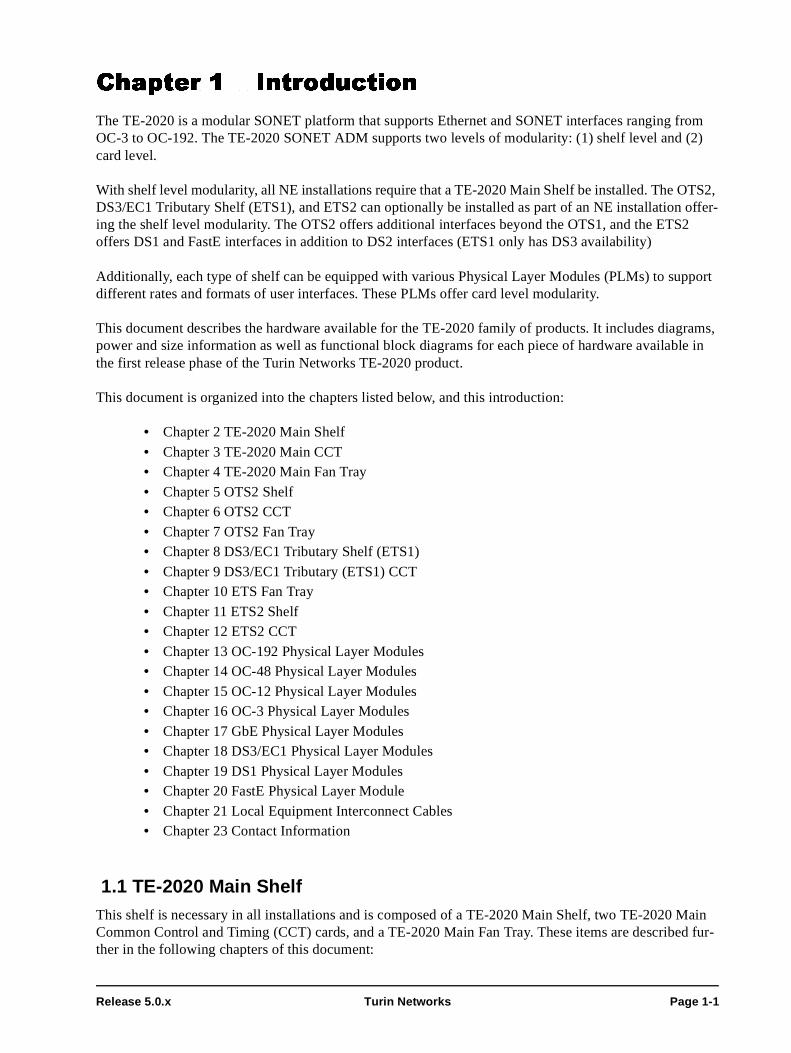
The TE-2020 is a modular SONET platform that supports Ethernet and SONET interfaces ranging from OC-3 to OC-192. The TE-2020 SONET ADM supports two levels of modularity: (1) shelf level and (2) card level.
With shelf level modularity, all NE installations require that a TE-2020 Main Shelf be installed. The OTS2, DS3/EC1 Tributary Shelf (ETS1), and ETS2 can optionally be installed as part of an NE installation offer-ing the shelf level modularity. The OTS2 offers additional interfaces beyond the OTS1, and the ETS2 offers DS1 and FastE interfaces in addition to DS2 interfaces (ETS1 only has DS3 availability)
Additionally, each type of shelf can be equipped with various Physical Layer Modules (PLMs) to support different rates and formats of user interfaces. These PLMs offer card level modularity.
This document describes the hardware available for the TE-2020 family of products. It includes diagrams, power and size information as well as functional block diagrams for each piece of hardware available in the first release phase of the Turin Networks TE-2020 product.
This document is organized into the chapters listed below, and this introduction:
• Chapter 2 TE-2020 Main Shelf
• Chapter 3 TE-2020 Main CCT• Chapter 4 TE-2020 Main Fan Tray
• Chapter 5 OTS2 Shelf• Chapter 6 OTS2 CCT
• Chapter 7 OTS2 Fan Tray• Chapter 8 DS3/EC1 Tributary Shelf (ETS1)
• Chapter 9 DS3/EC1 Tributary (ETS1) CCT• Chapter 10 ETS Fan Tray
• Chapter 11 ETS2 Shelf• Chapter 12 ETS2 CCT
• Chapter 13 OC-192 Physical Layer Modules• Chapter 14 OC-48 Physical Layer Modules
• Chapter 15 OC-12 Physical Layer Modules• Chapter 16 OC-3 Physical Layer Modules
• Chapter 17 GbE Physical Layer Modules• Chapter 18 DS3/EC1 Physical Layer Modules
• Chapter 19 DS1 Physical Layer Modules• Chapter 20 FastE Physical Layer Module
• Chapter 21 Local Equipment Interconnect Cables• Chapter 23 Contact Information
1.1 TE-2020 Main ShelfThis shelf is necessary in all installations and is composed of a TE-2020 Main Shelf, two TE-2020 Main Common Control and Timing (CCT) cards, and a TE-2020 Main Fan Tray. These items are described fur-ther in the following chapters of this document:
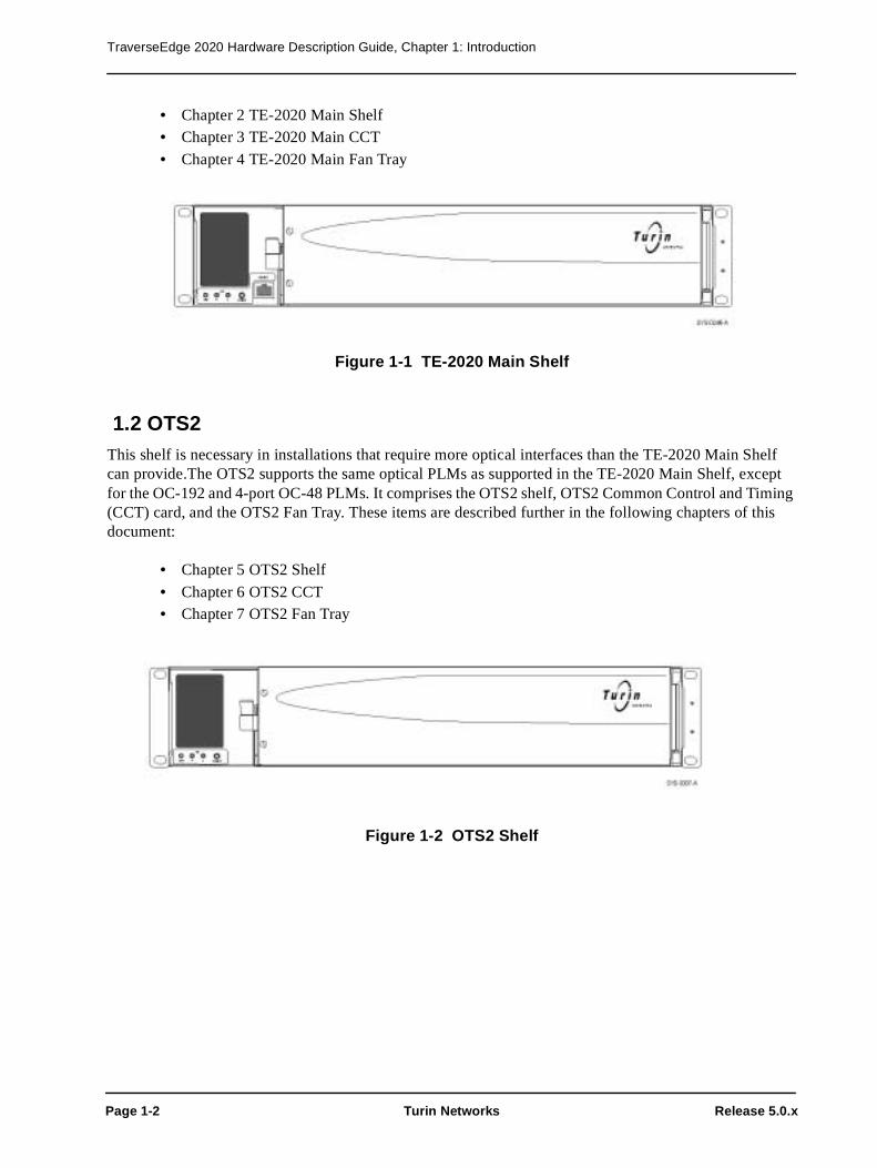
TraverseEdge 2020 Hardware Description Guide, Chapter 1: Introduction
Page 1-2 Turin Networks Release 5.0.x
• Chapter 2 TE-2020 Main Shelf• Chapter 3 TE-2020 Main CCT
• Chapter 4 TE-2020 Main Fan Tray
Figure 1-1 TE-2020 Main Shelf
1.2 OTS2This shelf is necessary in installations that require more optical interfaces than the TE-2020 Main Shelf can provide.The OTS2 supports the same optical PLMs as supported in the TE-2020 Main Shelf, except for the OC-192 and 4-port OC-48 PLMs. It comprises the OTS2 shelf, OTS2 Common Control and Timing (CCT) card, and the OTS2 Fan Tray. These items are described further in the following chapters of this document:
• Chapter 5 OTS2 Shelf
• Chapter 6 OTS2 CCT• Chapter 7 OTS2 Fan Tray
Figure 1-2 OTS2 Shelf
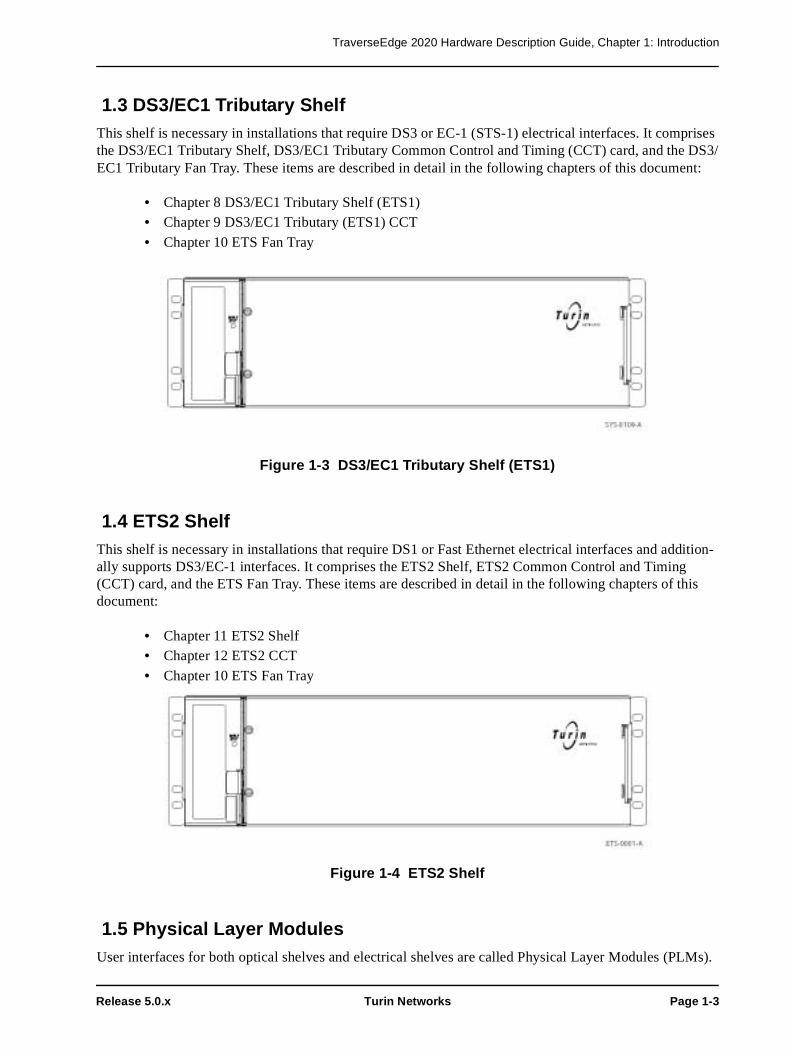
TraverseEdge 2020 Hardware Description Guide, Chapter 1: Introduction
Release 5.0.x Turin Networks Page 1-3
1.3 DS3/EC1 Tributary ShelfThis shelf is necessary in installations that require DS3 or EC-1 (STS-1) electrical interfaces. It comprises the DS3/EC1 Tributary Shelf, DS3/EC1 Tributary Common Control and Timing (CCT) card, and the DS3/EC1 Tributary Fan Tray. These items are described in detail in the following chapters of this document:
• Chapter 8 DS3/EC1 Tributary Shelf (ETS1) • Chapter 9 DS3/EC1 Tributary (ETS1) CCT
• Chapter 10 ETS Fan Tray
Figure 1-3 DS3/EC1 Tributary Shelf (ETS1)
1.4 ETS2 ShelfThis shelf is necessary in installations that require DS1 or Fast Ethernet electrical interfaces and addition-ally supports DS3/EC-1 interfaces. It comprises the ETS2 Shelf, ETS2 Common Control and Timing (CCT) card, and the ETS Fan Tray. These items are described in detail in the following chapters of this document:
• Chapter 11 ETS2 Shelf• Chapter 12 ETS2 CCT
• Chapter 10 ETS Fan Tray
Figure 1-4 ETS2 Shelf
1.5 Physical Layer ModulesUser interfaces for both optical shelves and electrical shelves are called Physical Layer Modules (PLMs).
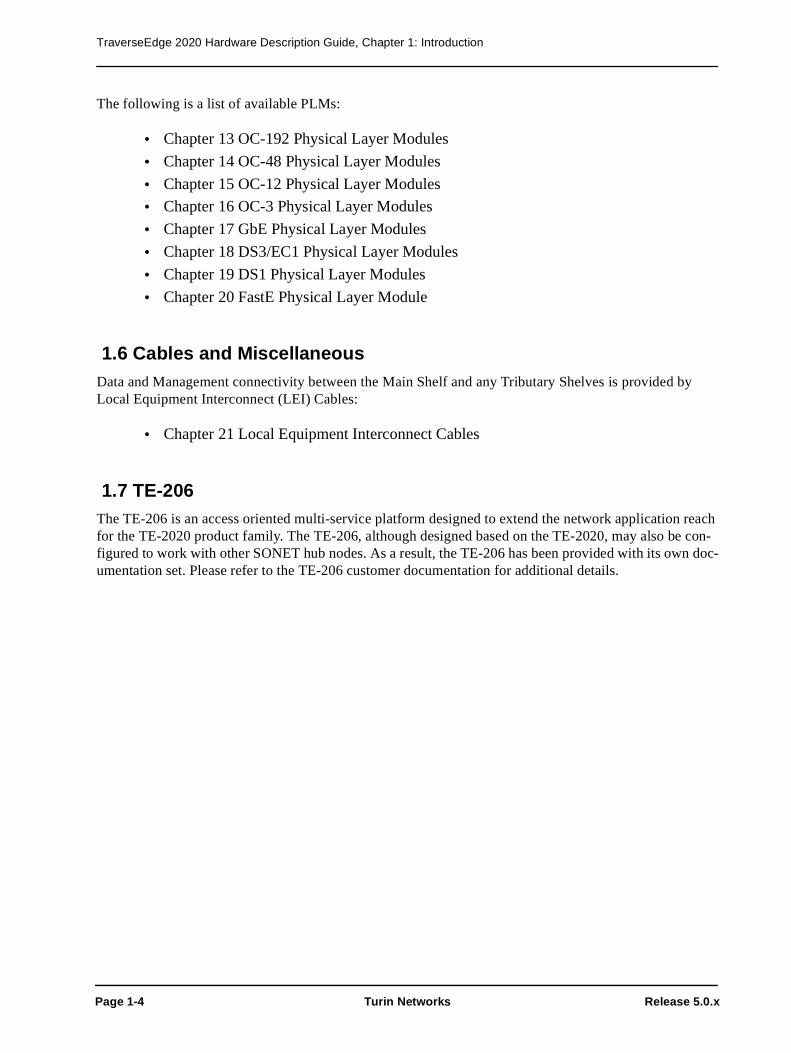
TraverseEdge 2020 Hardware Description Guide, Chapter 1: Introduction
Page 1-4 Turin Networks Release 5.0.x
The following is a list of available PLMs:
• Chapter 13 OC-192 Physical Layer Modules
• Chapter 14 OC-48 Physical Layer Modules
• Chapter 15 OC-12 Physical Layer Modules
• Chapter 16 OC-3 Physical Layer Modules
• Chapter 17 GbE Physical Layer Modules
• Chapter 18 DS3/EC1 Physical Layer Modules
• Chapter 19 DS1 Physical Layer Modules
• Chapter 20 FastE Physical Layer Module
1.6 Cables and MiscellaneousData and Management connectivity between the Main Shelf and any Tributary Shelves is provided by Local Equipment Interconnect (LEI) Cables:
• Chapter 21 Local Equipment Interconnect Cables
1.7 TE-206The TE-206 is an access oriented multi-service platform designed to extend the network application reach for the TE-2020 product family. The TE-206, although designed based on the TE-2020, may also be con-figured to work with other SONET hub nodes. As a result, the TE-206 has been provided with its own doc-umentation set. Please refer to the TE-206 customer documentation for additional details.

Release 5.0.x Turin NetworksPage 2-1
Chapter 2 TE-2020 Main Shelf
The TE-2020 Main Shelf is a two rack unit (RU) tall chassis that comes in sizes to fit either 19-inch or 23-inch rack applications. The additional plug-in units that can be installed within the shelf are the Fan Tray, CCTs, and Optical PLMs (Physical Layer Modules). The shelf provides the following features:
• Backplane• Fan tray slot
• CCT slots - upper and lower• Front 10/100 Ethernet RJ-45 craft user access port
• Two rear 10/100 Ethernet RJ-45 management ports• Serial rear management port
• Housekeeping, alarm connectors• Synchronization connectors
• LEI connectors• Power and ground connectors
• Mounting brackets• Front cover
2.1 TE-2020 Main Shelf - 19”The TE-2020 Main Shelf - 19” (WR-M2020-001-00000) is seen in Figure 2-1 and is designed for installa-tion in standard 19-inch Z-channel racks or standard channel racks. The actual width of the Main Shelf (to facilitate installation in a 19” rack) is 17.72”.
Table 2-1 TE-2020 Main Shelf - 19" Specifications
TE-2020 Main Shelf - 19” Specifications
Part Number WR-M2020-001-00000
Dimensions 3.47”H x17.72”W x12”D
Input Voltage Range -42.5 to -56.5 Volts DC
Weight 171.2 oz
Operating Temperature Range -5° to 55° C (23° to 131° F)0° to 40° C (32° to 104° F) with Tunable PLMs
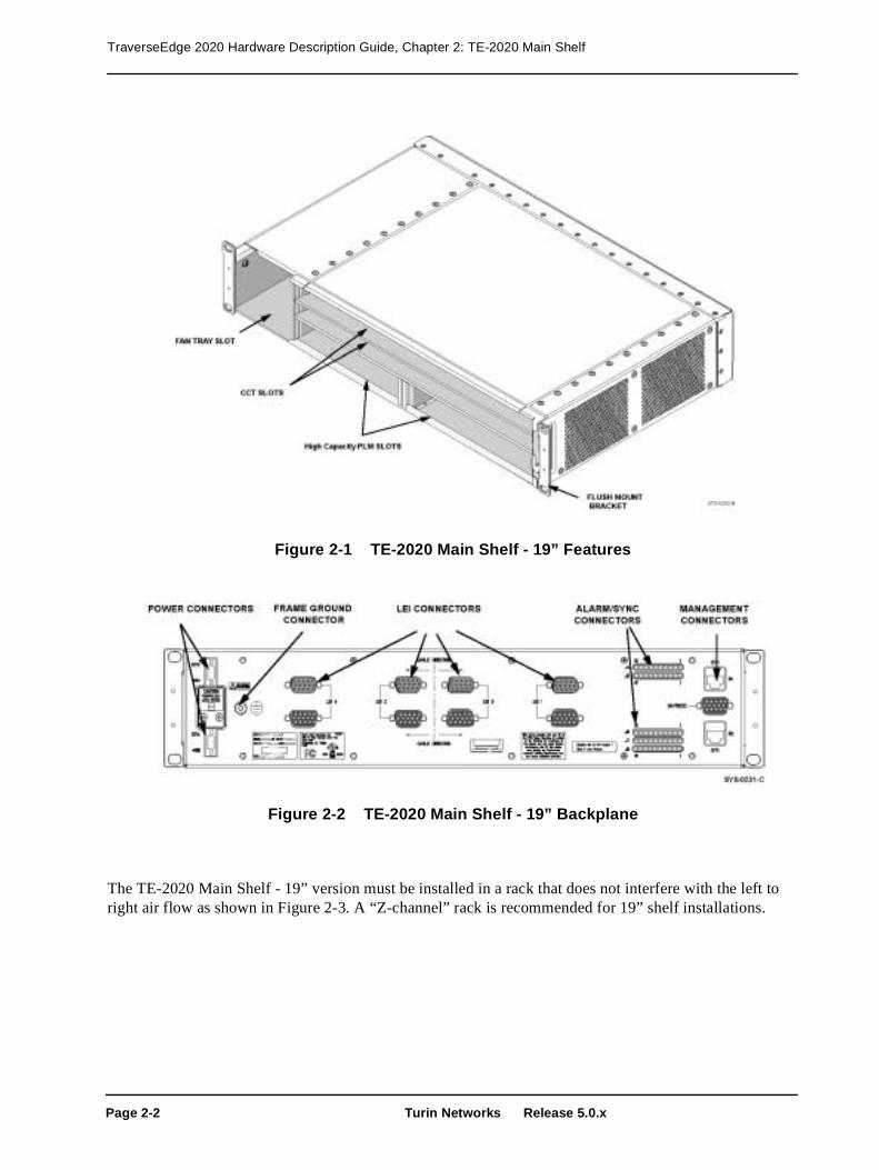
TraverseEdge 2020 Hardware Description Guide, Chapter 2: TE-2020 Main Shelf
Page 2-2 Turin Networks Release 5.0.x
Figure 2-1 TE-2020 Main Shelf - 19” Features
Figure 2-2 TE-2020 Main Shelf - 19” Backplane
The TE-2020 Main Shelf - 19” version must be installed in a rack that does not interfere with the left to right air flow as shown in Figure 2-3. A “Z-channel” rack is recommended for 19” shelf installations.

TraverseEdge 2020 Hardware Description Guide, Chapter 2: TE-2020 Main Shelf
Release 5.0.x Turin NetworksPage 2-3
Figure 2-3 TE-2020 Main Shelf - 19” Air Flow
2.2 TE-2020 Main Shelf - 23”The TE-2020 Main Shelf - 23” (WR-M2020-002-00000) differs from the 19” chassis in that it has integral air flow management extensions. The extension on the right redirects air flow from the TE-2020 Main Shelf to the rear of the chassis. The extension on the left provides external air into the left side of the chas-sis allowing the fans to push the air across the TE-2020 Main Shelf.
The TE-2020 Main Shelf - 23” (WR-M2020-002-00000) is seen in Figure 2-4 and is designed for installa-tion in standard 23-inch bay. The actual width of the Main Shelf (to facilitate installation in a 23” rack) is 21.36".
Table 2-2 TE-2020 Main Shelf - 23" Specifications
TE-2020 Main Shelf - 23” Specifications
Part Number WR-M2020-002-00000
Dimensions 3.47”H x21.36”W x12”D
Input Voltage Range -42.5 to -56.5 Volts DC
Weight 212.8 oz
Operating Temperature Range -5° to 55° C (23° to 131° F)0° to 40° C (32° to 104° F) with DWDM PLMs
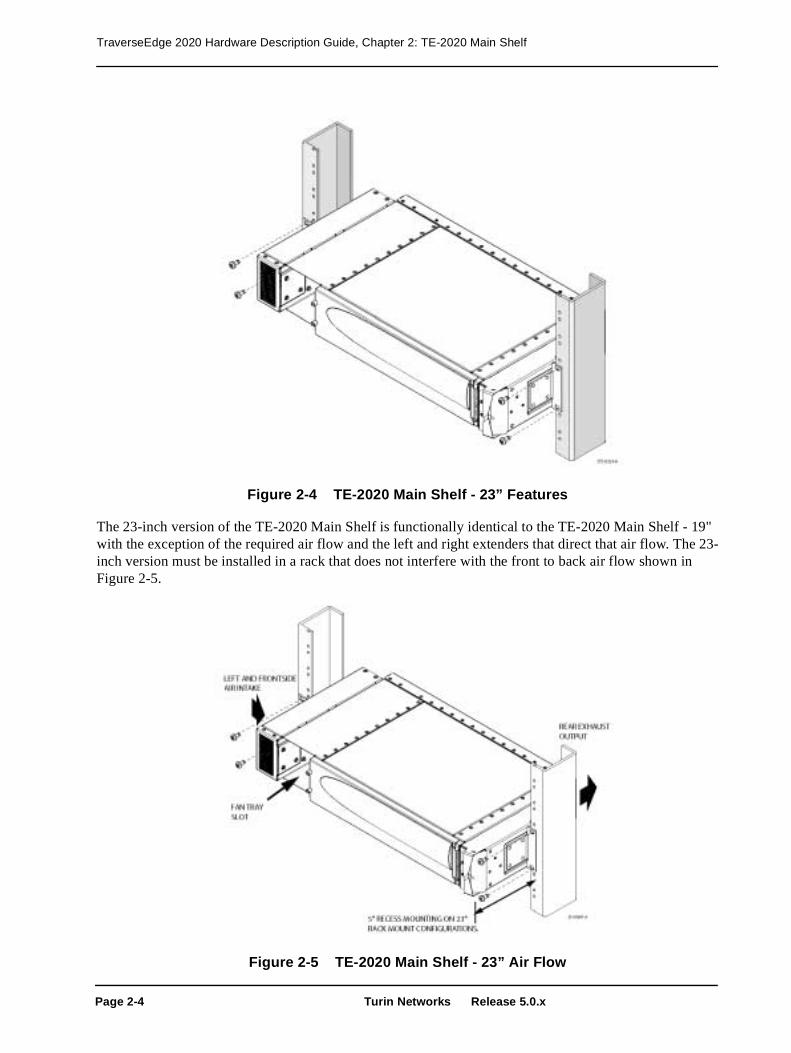
TraverseEdge 2020 Hardware Description Guide, Chapter 2: TE-2020 Main Shelf
Page 2-4 Turin Networks Release 5.0.x
Figure 2-4 TE-2020 Main Shelf - 23” Features
The 23-inch version of the TE-2020 Main Shelf is functionally identical to the TE-2020 Main Shelf - 19" with the exception of the required air flow and the left and right extenders that direct that air flow. The 23-inch version must be installed in a rack that does not interfere with the front to back air flow shown in Figure 2-5.
Figure 2-5 TE-2020 Main Shelf - 23” Air Flow

TraverseEdge 2020 Hardware Description Guide, Chapter 2: TE-2020 Main Shelf
Release 5.0.x Turin NetworksPage 2-5
2.3 Power Supply and ReturnThe TE-2020 Main Shelf provides redundant (A and B) -48Vdc power connectors to supply power to the system. Each connector has a removable plug to aid in the installation of Supply and Return wires. The A connector is labeled -48A for Supply and RTN for Return. The B connector is labeled -48B for Supply and RTN for Return. Refer to Figure 2-6.
Figure 2-6 A and B Power Connectors
The maximum, minimum and nominal input voltages (as measured across -48 and RTN) are shown in Table 2-3.
Table 2-3 A and B Power Connector Pinouts
2.4 Frame GroundThe TE-2020 Main Shelf provides a Frame Ground connection on the back of the shelf. This Frame Ground is used to terminate connector shields and is used on the system in ESD protection mechanisms. The Frame Ground is shown in Figure 2-6 between the power connectors and should be connected to the Frame or Chassis Ground for the bay.
2.5 BackplaneThe TE-2020 Main Shelf has a passive two rack unit backplane that provides connectivity between the CCTs and OC-192 PLMs, power distribution for all of the shelf plug-ins and connectivity between the external connectors and the CCTs and OC-192 PLMs.
2.6 LEI ConnectorsTo provide data and management traffic expansion into other shelves, the TE-2020 Main Shelf provides
Power Minimum Nominal Maximum
A -42.5 Vdc -48 Vdc -56.5 Vdc
B -42.5 Vdc -48 Vdc -56.5 Vdc
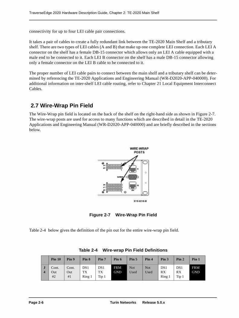
TraverseEdge 2020 Hardware Description Guide, Chapter 2: TE-2020 Main Shelf
Page 2-6 Turin Networks Release 5.0.x
connectivity for up to four LEI cable pair connections.
It takes a pair of cables to create a fully redundant link between the TE-2020 Main Shelf and a tributary shelf. There are two types of LEI cables (A and B) that make up one complete LEI connection. Each LEI A connector on the shelf has a female DB-15 connector which allows only an LEI A cable equipped with a male end to be connected to it. Each LEI B connector on the shelf has a male DB-15 connector allowing only a female connector on the LEI B cable to be connected to it.
The proper number of LEI cable pairs to connect between the main shelf and a tributary shelf can be deter-mined by referencing the TE-2020 Applications and Engineering Manual (WR-D2020-APP-040000). For additional information on inter-shelf LEI cable routing, refer to Chapter 21 Local Equipment Interconnect Cables.
2.7 Wire-Wrap Pin FieldThe Wire-Wrap pin field is located on the back of the shelf on the right-hand side as shown in Figure 2-7. The wire-wrap posts are used for access to many functions which are described in detail in the TE-2020 Applications and Engineering Manual (WR-D2020-APP-040000) and are briefly described in the sections below.
Figure 2-7 Wire-Wrap Pin Field
Table 2-4 below gives the definition of the pin out for the entire wire-wrap pin field.
Table 2-4 Wire-wrap Pin Field Definitions
Pin 10 Pin 9 Pin 8 Pin 7 Pin 6 Pin 5 Pin 4 Pin 3 Pin 2 Pin 1
J4
Cont. Out #2
Cont. Out #1
DS1 TX Ring 1
DS1 TX Tip 1
FRMGND
Not Used
Not Used
DS1 RX Ring 1
DS1 RX Tip 1
FRMGND

TraverseEdge 2020 Hardware Description Guide, Chapter 2: TE-2020 Main Shelf
Release 5.0.x Turin NetworksPage 2-7
Table 2-5 below shows groupings of pins by functions, defines the number of pins and gives a brief description of the pins and functionality.
J5
ACO Out
ACO In
DS1 TX Ring 2
DS1 TX Tip 2
FRMGND
Not Used
Not Used
DS1 RX Ring 2
DS1 RX Tip 2
FRMGND
J6
CR Aud. Alarm Out (–)
CR Aud. Alarm In (+)
CR Vis. Alarm Out (–)
CR Vis. Alarm In (+)
MJ Vis. Alarm Out (–)
MJ Vis. Alarm In(+)
MN Vis. Alarm Out(–)
MN Vis. Alarm In(+)
Not Used
Not Used
J7
MJ Aud. Alarm Out (–)
MJ Aud. Alarm In (+)
Env In#8
Env In#7
Env In#6
Env In#5
Env In#4
Env In#3
Env In#2
Env In#1
J8
MN Aud. Alarm Out (–)
MN Aud. Alarm In(+)
Env In#16
Env In#15
Env In#14
Env In#13
Env In#12
Env In#11
Env In#10
Env In#9
Table 2-5 Housekeeping Pin Group Function Definitions
Pin Count
Description Notes
2 BITS #1 Input Connector J4 - Pin 2 (Tip), Pin 3 (Ring) and Frame Ground (Pin 1)
2 BITS #1 Output Connector J4 - Pin 6 (Tip), Pin 7 (Ring) and Frame Ground (Pin 8)
2 BITS #2 Input Connector J5 - Pin 2 (Tip), Pin 3 (Ring) and Frame Ground (Pin 1)
2 BITS #2 Output Connector J5 - Pin 6 (Tip), Pin 7 (Ring) and Frame Ground (Pin 8)
2 Critical Alarm - Visual Connector J6 - Pin 7 (In), Pin 8 (Out)
2 Critical Alarm - Audible Connector J6 - Pin 9 (In), Pin 10 (Out)
2 Major Alarm - Visual Connector J6 - Pin 5 (In), Pin 6 (Out)
2 Major Alarm - Audible Connector J7 - Pin 9 (In), Pin 10 (Out)
2 Minor Alarm - Visual Connector J6 - Pin 3 (In), Pin 4 (Out)
2 Minor Alarm - Audible Connector J8 - Pin 9 (In), Pin 10 (Out)
16 Environmental Alarm Input Connector J7 - Pins 1-8 (Inputs 1 to 8)Connector J8 - Pins 1-8 (Inputs 9 to 16)
2 Control Output Connector J4 - Pin 9, Pin 10
2 Frame Ground Connector J4 - Pins 1 and 8 to be used for Shield for DS1 Interfaces Connector J5 - Pins 1 and 8 to be used for Shield for DS1 Interfaces
Table 2-4 Wire-wrap Pin Field Definitions
Pin 10 Pin 9 Pin 8 Pin 7 Pin 6 Pin 5 Pin 4 Pin 3 Pin 2 Pin 1

TraverseEdge 2020 Hardware Description Guide, Chapter 2: TE-2020 Main Shelf
Page 2-8 Turin Networks Release 5.0.x
2.7.1 Environmental Input Pins
Sixteen environmental input pins are provided so that the TE-2020 Main Shelf can monitor alarm outputs and actions from other equipment at the same site. The user can provision alarms to correspond to the input control pins.
The environmental input pins are all single ended inputs that can detect contact closure to ground (or return) on the external equipment. Under normal conditions, the circuit is open at the external device; under detect conditions, the circuit is closed. The environmental input pin detects a switch closing for the alarm circuit and creates a configured alarm. An example of an environmental alarm would be an open door of the facility where the TE-2020 Main Shelf is installed. Refer to Figure 2-8 for Environmental Input pin locations
Figure 2-8 Environmental Input Pins
2.7.2 External Output Control Pins
The equipment external output control pins are used to control equipment such as generators or air condi-tioners located at the same site. Under normal conditions, the circuit is open; in operated state, the circuit provides a path to ground (or return). The output control pin creates an open circuit with external equip-ment. When the user initiates a command, the circuit closes on the TE-2020, becoming a ground (or return)
8 Not Used Connector J4 - Pins 4 and 5Connector J5 - Pins 4 and 5Connector J6 - Pins 1 and 2
1 ACO Input Connector J5 - Pin 9
1 ACO Output Connector J5 - Pin 10
Table 2-5 Housekeeping Pin Group Function Definitions
Pin Count
Description Notes

TraverseEdge 2020 Hardware Description Guide, Chapter 2: TE-2020 Main Shelf
Release 5.0.x Turin NetworksPage 2-9
for the circuit. The external output control pins are single ended outputs.
Figure 2-9 External Output Control Pins
Table 2-6 Pinout for External Control Pins
NOTE: Voltage applied must be negative potential.
Connector Name ConnectorNumber
Pin Number
In/Out Max Current
Max Voltage
External Control 1 J4 9 Out 30 mA –60 Vdc
External Control 2 J4 10 Out 30 mA –60 Vdc
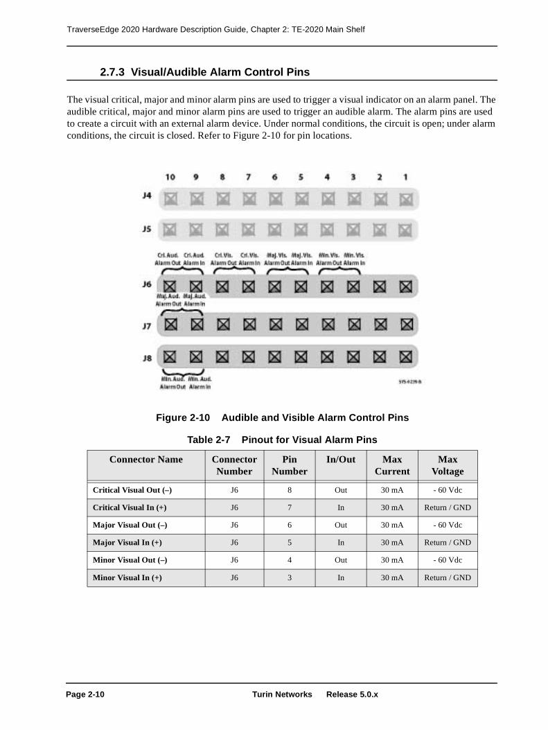
TraverseEdge 2020 Hardware Description Guide, Chapter 2: TE-2020 Main Shelf
Page 2-10 Turin Networks Release 5.0.x
2.7.3 Visual/Audible Alarm Control Pins
The visual critical, major and minor alarm pins are used to trigger a visual indicator on an alarm panel. The audible critical, major and minor alarm pins are used to trigger an audible alarm. The alarm pins are used to create a circuit with an external alarm device. Under normal conditions, the circuit is open; under alarm conditions, the circuit is closed. Refer to Figure 2-10 for pin locations.
Figure 2-10 Audible and Visible Alarm Control Pins
Table 2-7 Pinout for Visual Alarm Pins
Connector Name Connector Number
Pin Number
In/Out Max Current
MaxVoltage
Critical Visual Out (–) J6 8 Out 30 mA - 60 Vdc
Critical Visual In (+) J6 7 In 30 mA Return / GND
Major Visual Out (–) J6 6 Out 30 mA - 60 Vdc
Major Visual In (+) J6 5 In 30 mA Return / GND
Minor Visual Out (–) J6 4 Out 30 mA - 60 Vdc
Minor Visual In (+) J6 3 In 30 mA Return / GND

TraverseEdge 2020 Hardware Description Guide, Chapter 2: TE-2020 Main Shelf
Release 5.0.x Turin NetworksPage 2-11
NOTE: The polarity of the inputs should match the polarity of the connector.
2.7.4 Alarm Cut-Off (ACO) Control Pins
The Alarm Cut-Off (ACO) feature enables the TE-2020 to cut off the office audible alarm indications without changing the local alarm indications. The NE will remain able to transmit its current alarm or sta-tus condition if requested by the management system or other external command source.
The TE-2020 can silence the audible alarms for critical, major and minor alarms by an external piece of equipment at the same location by using the ACO feature. This ACO interface is a two pin connection that is controlled by an external device by changing from an open circuit to a closed circuit by shorting the two pins together. Refer to Figure 2-11. The ACO function is also available by pressing the ACO button on the front of the fan tray on the TE-2020 Main Shelf. The ACO can be connected at any time, but is generally connected at the time of initial installation.
Figure 2-11 Alarm Cut-Off Control Pins
Table 2-8 Pinout for Audible Alarm Pins
Connector Name Connector Number
Pin Number
In/Out Max Current
MaxVoltage
Critical Audible Out (–) J6 10 Out 30 mA - 60 Vdc
Critical Audible In (+) J6 9 In 30 mA Return / GND
Major Audible Out (–) J7 10 Out 30 mA - 60 Vdc
Major Audible In (+) J7 9 In 30 mA Return / GND
Minor Audible Out (–) J8 10 Out 30 mA - 60 Vdc
Minor Audible In (+) J8 9 In 30 mA Return / GND

TraverseEdge 2020 Hardware Description Guide, Chapter 2: TE-2020 Main Shelf
Page 2-12 Turin Networks Release 5.0.x
2.7.5 BITS Input/Derived Output Pins and Frame Ground
BITS Input 1 and 2 are external DS1 reference signals from Stratum 3 or better synchronization supply sources. External synchronization reference from a BITS clock is the preferred mode of synchronizing SONET network elements.
The TE-2020 Main Shelf can also distribute derived SONET-based synchronization signals via the BITS 1 and 2 output pins using DS1s derived from a terminating OC-n synchronization reference.
Two frame ground pins are included in this section because of their common use as shield termination for DS1 cables.
Figure 2-12 BITS Input/Derived Output Control Pins
Table 2-9 Pinout for BITS Pins
Connector Name Connector Number
PinNumber
In/Out
DS1 TX Tip 1 (Derived Output) J4 7 Out
DS1 TX Ring 1 (Derived Output) J4 8 Out
Ground J4 6
BITS RX Tip 1 (Input) J4 2 In
BITS RX Ring 1 (Input) J4 3 In
Ground J4 1
DS1 TX Tip 2 (Derived Output) J5 7 Out
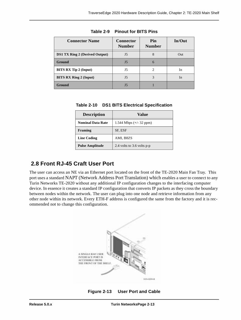
TraverseEdge 2020 Hardware Description Guide, Chapter 2: TE-2020 Main Shelf
Release 5.0.x Turin NetworksPage 2-13
2.8 Front RJ-45 Craft User PortThe user can access an NE via an Ethernet port located on the front of the TE-2020 Main Fan Tray. This port uses a standard NAPT (Network Address Port Translation) which enables a user to connect to any Turin Networks TE-2020 without any additional IP configuration changes to the interfacing computer device. In essence it creates a standard IP configuration that converts IP packets as they cross the boundary between nodes within the network. The user can plug into one node and retrieve information from any other node within its network. Every ETH-F address is configured the same from the factory and it is rec-ommended not to change this configuration.
Figure 2-13 User Port and Cable
DS1 TX Ring 2 (Derived Output) J5 8 Out
Ground J5 6
BITS RX Tip 2 (Input) J5 2 In
BITS RX Ring 2 (Input) J5 3 In
Ground J5 1
Table 2-10 DS1 BITS Electrical Specification
Description Value
Nominal Data Rate 1.544 Mbps (+/- 32 ppm)
Framing SF, ESF
Line Coding AMI, B8ZS
Pulse Amplitude 2.4 volts to 3.6 volts p-p
Table 2-9 Pinout for BITS Pins
Connector Name Connector Number
PinNumber
In/Out

TraverseEdge 2020 Hardware Description Guide, Chapter 2: TE-2020 Main Shelf
Page 2-14 Turin Networks Release 5.0.x
This interface port can be accessed directly using a standard Ethernet cable. Refer to Chapter 22 Interface Cables for connector pinouts.
Figure 2-14 Front ETH-F User Interface Cable
2.9 Rear RJ-45 Ethernet PortsThe rear RJ-45 Ethernet ports are used for connection to EMS (e.g., TN-Xpert) systems as well as support for TN-Relay (Remote IP DCN Transport). The ports are numbered R1 and R2 as shown in Figure 2-15. The two ports are functionally identical and require configuration.
Figure 2-15 Rear RJ-45 ports
Both rear Ethernet ports are 10/100Base-T auto sensing or user configurable. The pinout for both RJ-45 ports is shown in Table 2-12 . These are standard RJ-45 10/100Base-T Ethernet connections and can be connected to using a standard CAT-5 Ethernet cable. The Ethernet ports support the functions in Table 2-11 .
• Tunnel: IP encapsulation came be run over the interface allowing for a UNIX DMS to establish connectivity • OPSF: Running OSPF over the interface in a point to point tunneled application
• TL-1: A TL-1 session can be established with the IP address of the port • Http: A web session can be established with the IP address of the port
Table 2-11 Ethernet Operations
Port Tunnel OSPF TL-1 Http Alien IP
Front No No Yes Yes No
Rear 1 Yes No Yes Yes Yes
Rear 2 Yes Yes No No Yes

TraverseEdge 2020 Hardware Description Guide, Chapter 2: TE-2020 Main Shelf
Release 5.0.x Turin NetworksPage 2-15
• Alien IP: Third Party IP packets can be routed through the port
NOTE: An NTP server can only be configured on ETH-R1 or ETH-R2, not on ETH-F
2.10 Rear Serial Communications Port A serial communications port is provided at the rear of the shelf between the two Ethernet ports. Refer to Figure 2-16. This is a male DB-9 sub-miniature connection that may be used with a “straight-through” cable with female connectors at both ends to connect to a users laptop com-puter. Using a “roll-over” cable the user can connect a modem to the serial interface port to remotely access the system. This interface is provided as a “as needed” TL-1 interface, most pro-visioning and Craft access will be performed through the front User Interface RJ-45 Craft port.
Figure 2-16 Rear Serial Interface Port
Pinouts for the rear Serial Interface Port can be found in the following table.
Table 2-12 Rear Management RJ-45 Port Pinouts
Pin # Description
1 Ethernet Transmit Pos
2 Ethernet Transmit Neg
3 Ethernet Receive Pos
4 Not Used
5 Not Used
6 Ethernet Receive Neg
7 Not Used
8 Ground
Table 2-13 Rear Serial Interface Port Pinouts
Pin # Description
2 TD (RS232 Transmit Data

TraverseEdge 2020 Hardware Description Guide, Chapter 2: TE-2020 Main Shelf
Page 2-16 Turin Networks Release 5.0.x
2.11 Front CoverThe front cover is designed to protect the exposed fiber that connects into the TE-2020 Main Shelf and to give the installation a neat appearance.
NOTE: Special care is advised when removing the cover. The user must hold the cover securely to prevent dropping.
Figure 2-17 TE-2020 Main Shelf Front Cover
3 RS (RS232 Receive Data)
5 SG (Signal Ground)
Table 2-13 Rear Serial Interface Port Pinouts
Pin # Description

Release 5.0.x Turin NetworksPage 3-1
Chapter 3 TE-2020 Main CCT
The TE-2020 Main Shelf Common Control and Timing (CCT) plug-in module is designed for installation in the TE-2020 Main Shelf. The CCTs can, in turn, have Physical Layer Modules (PLMs) installed in them.
Figure 3-1 TE-2020 Main CCT
3.1 ConfigurationsThe CCT supports the card level configurations below. Consult the TE-2020 Applications and Engineering Manual (WR-D2020-APP-040000) for configuration details.
• 1+1 Protected
• Unprotected
3.2 Physical SpecificationsThe TE-2020 Main CCT provides the power, synchronization, processor and cross-connect functions for the TE-2020 Main Shelf. For each TE-2020 Main Shelf, there are two TE-2020 Main CCTs installed for protected operation. Each CCT can be individually installed and removed with the system operational. If only one CCT is installed, the TE-2020 Main Shelf features do not have a redundant backup.
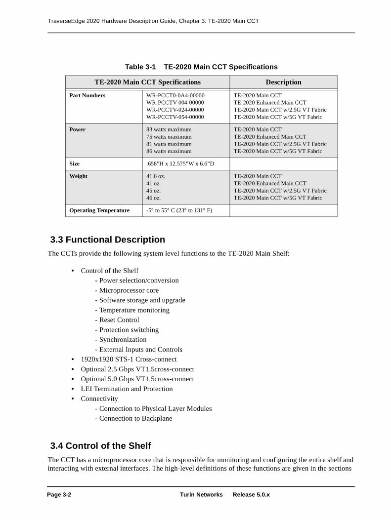
TraverseEdge 2020 Hardware Description Guide, Chapter 3: TE-2020 Main CCT
Page 3-2 Turin Networks Release 5.0.x
3.3 Functional DescriptionThe CCTs provide the following system level functions to the TE-2020 Main Shelf:
• Control of the Shelf- Power selection/conversion
- Microprocessor core- Software storage and upgrade
- Temperature monitoring- Reset Control
- Protection switching- Synchronization
- External Inputs and Controls • 1920x1920 STS-1 Cross-connect
• Optional 2.5 Gbps VT1.5cross-connect• Optional 5.0 Gbps VT1.5cross-connect
• LEI Termination and Protection• Connectivity
- Connection to Physical Layer Modules- Connection to Backplane
3.4 Control of the Shelf The CCT has a microprocessor core that is responsible for monitoring and configuring the entire shelf and interacting with external interfaces. The high-level definitions of these functions are given in the sections
Table 3-1 TE-2020 Main CCT Specifications
TE-2020 Main CCT Specifications Description
Part Numbers WR-PCCT0-0A4-00000WR-PCCTV-004-00000WR-PCCTV-024-00000WR-PCCTV-054-00000
TE-2020 Main CCTTE-2020 Enhanced Main CCT TE-2020 Main CCT w/2.5G VT Fabric TE-2020 Main CCT w/5G VT Fabric
Power 83 watts maximum75 watts maximum81 watts maximum86 watts maximum
TE-2020 Main CCTTE-2020 Enhanced Main CCT TE-2020 Main CCT w/2.5G VT FabricTE-2020 Main CCT w/5G VT Fabric
Size .658”H x 12.575”W x 6.6”D
Weight 41.6 oz.41 oz.45 oz.46 oz.
TE-2020 Main CCTTE-2020 Enhanced Main CCT TE-2020 Main CCT w/2.5G VT FabricTE-2020 Main CCT w/5G VT Fabric
Operating Temperature -5° to 55° C (23° to 131° F)
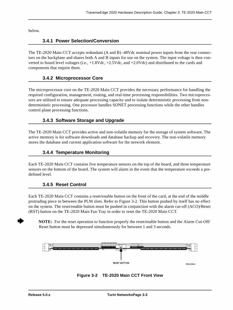
TraverseEdge 2020 Hardware Description Guide, Chapter 3: TE-2020 Main CCT
Release 5.0.x Turin NetworksPage 3-3
below.
3.4.1 Power Selection/Conversion
The TE-2020 Main CCT accepts redundant (A and B) -48Vdc nominal power inputs from the rear connec-tors on the backplane and shares both A and B inputs for use on the system. The input voltage is then con-verted to board level voltages (i.e., +1.8Vdc, +2.5Vdc, and +2.0Vdc) and distributed to the cards and components that require them.
3.4.2 Microprocessor Core
The microprocessor core on the TE-2020 Main CCT provides the necessary performance for handling the required configuration, management, routing, and real-time processing responsibilities. Two microproces-sors are utilized to ensure adequate processing capacity and to isolate deterministic processing from non-deterministic processing. One processor handles SONET processing functions while the other handles control plane processing functions.
3.4.3 Software Storage and Upgrade
The TE-2020 Main CCT provides active and non-volatile memory for the storage of system software. The active memory is for software downloads and database backup and recovery. The non-volatile memory stores the database and current application software for the network element.
3.4.4 Temperature Monitoring
Each TE-2020 Main CCT contains five temperature sensors on the top of the board, and three temperature sensors on the bottom of the board. The system will alarm in the event that the temperature exceeds a pre-defined level.
3.4.5 Reset Control
Each TE-2020 Main CCT contains a reset/enable button on the front of the card, at the end of the middle protruding piece in between the PLM slots. Refer to Figure 3-2. This button pushed by itself has no effect on the system. The reset/enable button must be pushed in conjunction with the alarm cut-off (ACO)/Reset (RST) button on the TE-2020 Main Fan Tray in order to reset the TE-2020 Main CCT.
NOTE: For the reset operation to function properly the reset/enable button and the Alarm Cut-Off/Reset button must be depressed simultaneously for between 1 and 3 seconds.
Figure 3-2 TE-2020 Main CCT Front View

TraverseEdge 2020 Hardware Description Guide, Chapter 3: TE-2020 Main CCT
Page 3-4 Turin Networks Release 5.0.x
3.4.6 Protection Switching
The CCT is responsible for detecting and properly switching to a redundant source for protected equip-ment failures within the shelf. The equipment failures can be on PLMs or on the CCTs themselves.
3.4.7 Synchronization
Each TE-2020 Main CCT contains a synchronization unit which provides a Stratum 3 synchronization ref-erence for holdover. Circuitry to recover and distribute timing from any of the PLMs or BITS inputs is also provided on the CCTs.
3.4.8 External Inputs and Controls
The TE-2020 Main CCT controls the circuitry that drives the external control connectors and the circuitry that monitors the external alarm connections.
3.5 1920 x 1920 STS-1 Cross-connectThe cross-connect matrix provides a non-blocking 1920 x 1920 STS-1 cross-connect allowing any-port-to-any-port connection flexibility for STS-1, STS-3c, STS-12c, STS-48c, and STS-192c connection types on the TE-2020 Main Shelf, or any of the tributary shelves. All cross-connects are made through the TE-2020 Main Shelf except for hair-pinned connections on the OTS2 which are made locally on the tributary shelf.
3.5.1 2.5 Gbps and 5 Gbps VT1.5 Cross-connect
The OTS2 CCT may be ordered with a VT1.5 cross-connect option ineither 2.5 Gbps or 5 Gbps capacity. The VT1.5 cross-connect is used to support VT1.5 UPSR capability.
3.6 LEI Termination and ProtectionThe TE-2020 Main CCT has protected electrical interfaces for interconnection to other Turin Networks tributary shelves. Each LEI cable is capable of carrying two 2.488 Gbs bidirectional signals up to 10 meters. The LEI cables connect to the passive backplane at the rear of the shelf. The CCT is responsible for selecting the appropriate signal to use for data and management traffic as part of the protection mechanism.
3.7 Connectivity
3.7.1 Connection to Physical Layer Modules
The PLM connector mates with the leading edge (inserted first in the PLM slot) CCT connector on the PLM. This interface provides power as well as data and management connectivity between the CCT and the PLMs.
3.7.2 Connection to Backplane

TraverseEdge 2020 Hardware Description Guide, Chapter 3: TE-2020 Main CCT
Release 5.0.x Turin NetworksPage 3-5
The backplane connector on the leading edge (inserted first in the CCT slot) of the CCT provides power as well as data and management connectivity between pairs of CCTs and the other shelves.

TraverseEdge 2020 Hardware Description Guide, Chapter 3: TE-2020 Main CCT
Page 3-6 Turin Networks Release 5.0.x

Release 5.0.x Turin Networks Page 4-1
Chapter 4 TE-2020 Main Fan Tray
The TE-2020 Main Shelf is designed to accept a single fan tray. This fan tray comprises twelve individual fans that operate individually. The failure of any of the individual fans will result in an alarm condition, but the fan tray unit will continue to operate. The fan tray is necessary for proper operation. Figure 4-1 below shows the TE-2020 Main Fan Tray.
Figure 4-1 TE-2020 Main Fan Tray
4.1 Functional DescriptionThe fan tray consists of an air intake for the shelf, status LEDs, alarm cut-off (ACO)/reset (RST) button,
Table 4-1 TE-2020 Main Fan Tray Specifications
TE-2020 Main Fan Tray Specifications
Part Number WR-PFAN0-004-00000
Power 36 watts maximum
Size 3.34”H x 3”W x 10.8”D
Weight 33.6 oz.
Operating Temperature -5° to 55° C (23° to 131° F)

TraverseEdge 2020 Hardware Description Guide, Chapter 4: TE-2020 Main Fan Tray
Page 4-2 Turin Networks Release 5.0.x
front user management port, twelve fans, input/output block, and a 2 RU fan filter. Communication between the CCT and the module is via the backplane.
Under normal operation conditions, the fan tray will regulate the internal system temperature and does not require attention.
If a single fan fails, a minor alarm is issued. If two fans fail, a critical alarm is issued. The remaining fans continue to operate. The system is designed to accommodate two fan failures and maintain normal opera-tion.
4.1.1 Front Panel
The front panel of the TE-2020 Main Fan Tray shown in Figure 4-2 consists of the air intake, status LEDs, alarm cut-off (ACO)/reset button, and the front user port.
Figure 4-2 TE-2020 Main Fan Tray Front Panel
4.1.2 Air Intake
The air intake for the TE-2020 Main Shelf is on the front of the TE-2020 Main Fan Tray, and on the left side of the 23-inch shelf air intake. The front fan tray intake is covered with a wire mesh shield. In 23” applications, an additional filter is used which covers the front and side of the extension air intake as shown in Figure 4-3.

TraverseEdge 2020 Hardware Description Guide, Chapter 4: TE-2020 Main Fan Tray
Release 5.0.x Turin Networks Page 4-3
Figure 4-3 23” Extension Air Filter
4.1.3 LEDs
The Fan Tray LEDs are for the Upper TE-2020 Main CCT board (U), the Lower TE-2020 Main CCT board (L), and the NE Status (STAT). The LEDs will be green if operations are normal. If the LEDs become red or yellow, an alarm has been issued. The alarm status colors are shown in Table 4-2 and Table 4-3 .
Table 4-2 Upper and Lower CCT Status LED Behavior
Representation LED Behavior
Critical or Major Alarm Condition on CCT Red
Minor Alarm Condition on CCT Yellow
Normal, No Alarm Conditions Green
No Power, Out of Service Off
Table 4-3 System Status LED Behavior
Representation LED Behavior
Critical or Major Alarm Condition on Shelf or Tributary Shelf
Red
Minor Alarm Condition on Shelf Yellow
Normal, No Alarm Conditions Green
No Power, Out of Service Off

TraverseEdge 2020 Hardware Description Guide, Chapter 4: TE-2020 Main Fan Tray
Page 4-4 Turin Networks Release 5.0.x
4.1.4 Alarm Cut-Off (ACO)/Reset (RST)
The ACO/RST button is located on the front of the TE-2020 Main Fan Tray.
The Alarm Cut-Off is used to cut off the office audible alarm indicators. The NE will remain able to trans-mit its current alarm or status condition if requested by the management system or other external command source. In general, centralized indications should not be affected by the ACO. It retires the central office (CO) alarm audible indicators without clearing existing indicators on the NE. The ACO/RST button must be depressed for five seconds to issue an ACO.
The ACO/RST button will issue a lamp test if pressed by itself and immediately released.
The Alarm Cut-Off (ACO)/Reset (RST) button can be pushed in conjunction with the reset button on a TE-2020 Main CCT to reset the TE-2020 Main CCT.
Caution: If both the TE-2020 Main CCT reset button and the TE-2020 Main Fan Tray button are pushed together, traffic can be dropped.
4.1.5 User Port
The user can access an NE via an Ethernet port located on the front of the TE-2020 Main Fan Tray. This interface port can be accessed directly using a standard Ethernet cable.
Figure 4-4 User Interface Wiring Scheme
4.1.6 2 RU Fan Filter
The 2 RU fan filter (WR-PFLTR-002-00000) runs the length of the fan tray to the left of the fans if facing the TE-2020 Main Shelf. It is designed to optimize the air filtering process. The fan filter has an air-flow direction indicator arrow label, and it should be installed per the indicator. Replacement chassis filters can also be ordered (WR-PFLTR-002-00000 for single filters, or WR-PFLTR-X02-00000 for a pack of 10 fil-ters). It is recommended that the fan filter be changed every six months when operating under normal Cen-tral Office conditions. The filter cannot be cleaned.
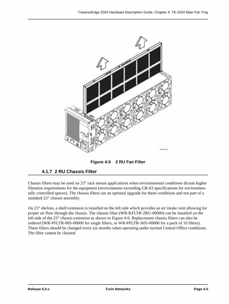
TraverseEdge 2020 Hardware Description Guide, Chapter 4: TE-2020 Main Fan Tray
Release 5.0.x Turin Networks Page 4-5
Figure 4-5 2 RU Fan Filter
4.1.7 2 RU Chassis Filter
Chassis filters may be used on 23” rack mount applications when environmental conditions dictate higher filtration requirements for the equipment (environments exceeding GR-63 specifications for environmen-tally controlled spaces). The chassis filters are an optional upgrade for these conditions and not part of a standard 23” chassis assembly.
On 23” shelves, a shelf extension is installed on the left side which provides an air intake vent allowing for proper air flow through the chassis. The chassis filter (WR-KFLTR-2RU-00000) can be installed on the left side of the 23” chassis extension as shown in Figure 4-6. Replacement chassis filters can also be ordered (WR-PFLTR-005-00000 for single filters, or WR-PFLTR-X05-00000 for a pack of 10 filters). These filters should be changed every six months when operating under normal Central Office conditions. The filter cannot be cleaned.
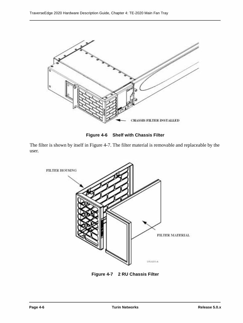
TraverseEdge 2020 Hardware Description Guide, Chapter 4: TE-2020 Main Fan Tray
Page 4-6 Turin Networks Release 5.0.x
Figure 4-6 Shelf with Chassis Filter
The filter is shown by itself in Figure 4-7. The filter material is removable and replaceable by the user.
Figure 4-7 2 RU Chassis Filter
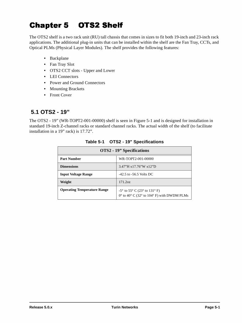
Release 5.0.x Turin Networks Page 5-1
Chapter 5 OTS2 Shelf
The OTS2 shelf is a two rack unit (RU) tall chassis that comes in sizes to fit both 19-inch and 23-inch rack applications. The additional plug-in units that can be installed within the shelf are the Fan Tray, CCTs, and Optical PLMs (Physical Layer Modules). The shelf provides the following features:
• Backplane• Fan Tray Slot
• OTS2 CCT slots - Upper and Lower• LEI Connectors
• Power and Ground Connectors• Mounting Brackets
• Front Cover
5.1 OTS2 - 19”The OTS2 - 19” (WR-TOPT2-001-00000) shelf is seen in Figure 5-1 and is designed for installation in standard 19-inch Z-channel racks or standard channel racks. The actual width of the shelf (to facilitate installation in a 19” rack) is 17.72”.
Table 5-1 OTS2 - 19" Specifications
OTS2 - 19” Specifications
Part Number WR-TOPT2-001-00000
Dimensions 3.47”H x17.76”W x12”D
Input Voltage Range -42.5 to -56.5 Volts DC
Weight 171.2oz
Operating Temperature Range -5° to 55° C (23° to 131° F)0° to 40° C (32° to 104° F) with DWDM PLMs

TraverseEdge 2020 Hardware Description Guide, Chapter 5: OTS2 Shelf
Page 5-2 Turin Networks Release 5.0.x
Figure 5-1 OTS2 - 19” Features
Figure 5-2 OTS2 - 19” Backplane
The OTS2 - 19” version must be installed in a rack that does not interfere with the left to right air flow as shown in Figure 5-3. A “Z-channel” rack is recommended for 19” shelf installations.

TraverseEdge 2020 Hardware Description Guide, Chapter 5: OTS2 Shelf
Release 5.0.x Turin Networks Page 5-3
Figure 5-3 OTS2 - 19” Air Flow
5.2 OTS2 - 23”The OTS2 - 23” (WR-TOPT2-002-00000) has additional air management chambers not found on the 19” chassis. The extension on the right redirects air flow from the OTS2 to the rear of the chassis. The exten-sion on the left provides external air into the left side of the chassis allowing the fans to push the air across the OTS2.
The OTS2 - 23” is seen in Figure 5-4 and is designed for installation in a standard 23-inch bay. The actual width of the shelf (to facilitate installation in a 23” rack) is 21.36".
Table 5-2 OTS2 - 23" Specifications
OTS2 - 23” Specifications
Part Number WR-TOPT2-002-00000
Dimensions 3.47”H x21.36”W x12”D
Input Voltage Range -42.5 to -56.5 Volts DC
Weight 212.8oz
Operating Temperature Range -5° to 55° C (23° to 131° F)0° to 40° C (32° to 104° F) with Tunable PLMs
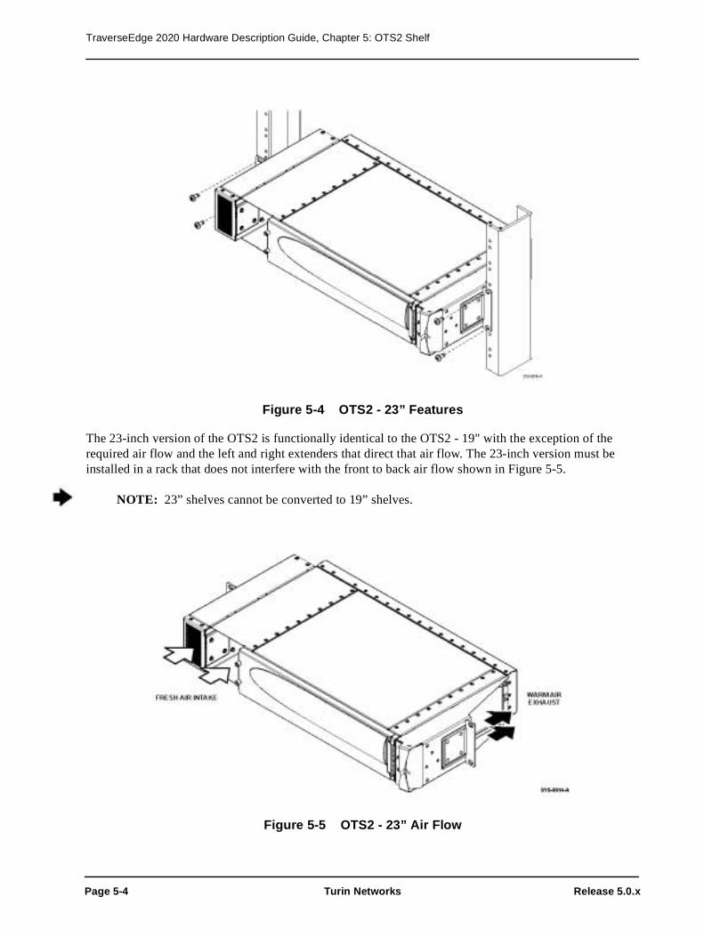
TraverseEdge 2020 Hardware Description Guide, Chapter 5: OTS2 Shelf
Page 5-4 Turin Networks Release 5.0.x
Figure 5-4 OTS2 - 23” Features
The 23-inch version of the OTS2 is functionally identical to the OTS2 - 19" with the exception of the required air flow and the left and right extenders that direct that air flow. The 23-inch version must be installed in a rack that does not interfere with the front to back air flow shown in Figure 5-5.
NOTE: 23” shelves cannot be converted to 19” shelves.
Figure 5-5 OTS2 - 23” Air Flow

TraverseEdge 2020 Hardware Description Guide, Chapter 5: OTS2 Shelf
Release 5.0.x Turin Networks Page 5-5
5.3 Power Supply and ReturnThe OTS2 provides redundant (A and B) -48Vdc power connectors to supply power to the system. Each connector has a removable plug to aid in the installation of Supply and Return wires. The A connector is labeled -48A for Supply and RTN for Return. The B connector is labeled -48B for Supply and RTN for Return. Refer to Figure 5-6.
Figure 5-6 A and B Power Connectors
The maximum, minimum, and nominal input voltages (as measured across -48 and RTN) are shown in Table 2-3.
Table 5-3 A and B Power Connector Pinouts
5.4 Frame GroundThe OTS2 provides a Frame Ground connection on the back of the shelf. This Frame Ground is used to ter-minate connector shields and is used on the system in ESD protection mechanisms. The Frame Ground is shown in Figure 5-6 between the power connectors and should be connected to the Frame or Chassis Ground for the bay.
5.5 BackplaneThe OTS2 has a passive two rack unit backplane that provides connectivity between the CCTs and optical PLMs, power distribution for all of the shelf plug-ins, and connectivity between the external connectors, CCTs and optical PLMs.
5.6 LEI Connectors
Power Minimum Nominal Maximum
A -42.5 Vdc -48 Vdc -56.5 Vdc
B -42.5 Vdc -48 Vdc -56.5 Vdc

TraverseEdge 2020 Hardware Description Guide, Chapter 5: OTS2 Shelf
Page 5-6 Turin Networks Release 5.0.x
To provide data and management traffic expansion into other shelves, the OTS2 provides connectivity for up to four LEI cable pair connections.
It takes a pair of cables to create a fully redundant link between the OTS2 and the TE-2020 Main Shelf. There are two types of LEI cables (A and B) that make up one complete LEI connection. Each LEI A con-nector on the shelf has a female DB-15 connector which allows only an LEI A cable equipped with a male end to be connected to it. Each LEI B connector on the shelf has a male DB-15 connector allowing only a female connector on the LEI B cable to be connected to it.
The proper number of LEI cable pairs to connect between the main shelf and a tributary shelf can be deter-mined by referencing the TE-2020 Applications and Engineering Manual (WR-D2020-APP-040000). For additional information on inter-shelf LEI cable routing, refer to Chapter 21 Local Equipment Interconnect Cables.
5.7 Front CoverThe front cover is designed to protect the exposed fiber that connects into the OTS2 and to give the instal-lation a neat appearance.
NOTE: Special care is advised when removing the cover. The user must hold the cover securely to prevent dropping.
Figure 5-7 OTS2 Front Cover
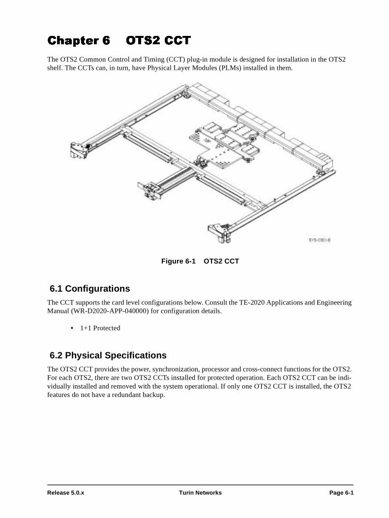
Release 5.0.x Turin Networks Page 6-1
Chapter 6 OTS2 CCT
The OTS2 Common Control and Timing (CCT) plug-in module is designed for installation in the OTS2 shelf. The CCTs can, in turn, have Physical Layer Modules (PLMs) installed in them.
Figure 6-1 OTS2 CCT
6.1 ConfigurationsThe CCT supports the card level configurations below. Consult the TE-2020 Applications and Engineering Manual (WR-D2020-APP-040000) for configuration details.
• 1+1 Protected
6.2 Physical SpecificationsThe OTS2 CCT provides the power, synchronization, processor and cross-connect functions for the OTS2. For each OTS2, there are two OTS2 CCTs installed for protected operation. Each OTS2 CCT can be indi-vidually installed and removed with the system operational. If only one OTS2 CCT is installed, the OTS2 features do not have a redundant backup.

TraverseEdge 2020 Hardware Description Guide, Chapter 6: OTS2 CCT
Page 6-2 Turin Networks Release 5.0.x
6.3 Functional DescriptionThe CCTs provide the following shelf level functions to the OTS2:
• Control of the Shelf- Power selection/conversion
- Microprocessor core- Software storage and upgrade
- Temperature monitoring- Reset Control
- Protection switching for failure conditions- Timing recovery and distribution
- Synchronization• Optional 2.5 Gbps VT1.5cross-connect
• Optional 5.0 Gbps VT1.5cross-connect• SONET/SDH Processing
• Local hairpinning• Local Equipment Interconnect (LEI)
• Connectivity- Connection to Physical Layer Modules
- Connection to Backplane
6.3.1 Power Selection/Conversion
The OTS2 CCT accepts redundant (A and B) -48Vdc nominal power inputs from the rear connectors on the backplane and shares both A and B inputs for use on the system. The input voltage is then converted to
Table 6-1 OTS2 CCT Specifications
OTS2 CCT Specifications Description
Part Numbers WR-PCCT0-0A5-00000WR-PCCTV-005-00000WR-PCCTV-025-00000WR-PCCTV-055-00000
OTS2 CCTOTS2 Enhanced Main CCT OTS2 CCT w/2.5G VT Fabric OTS2 CCT w/5G VT Fabric
Power 83 watts maximum75 watts maximum81 watts maximum86 watts maximum
OTS2 CCTOTS2 Enhanced Main CCT OTS2 CCT w/2.5G VT FabricOTS2 CCT w/5G VT Fabric
Size .658”H x 12.575”W x 6.6”D
Weight 41.6 oz.41 oz.45 oz.46 oz.
OTS2 CCTOTS2 Enhanced Main CCT OTS2 CCT w/2.5G VT FabricOTS2 CCT w/5G VT Fabric
Operating Temperature -5° to 55° C (23° to 131° F)
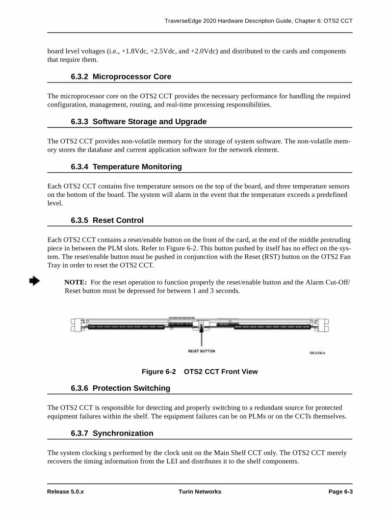
TraverseEdge 2020 Hardware Description Guide, Chapter 6: OTS2 CCT
Release 5.0.x Turin Networks Page 6-3
board level voltages (i.e., +1.8Vdc, +2.5Vdc, and +2.0Vdc) and distributed to the cards and components that require them.
6.3.2 Microprocessor Core
The microprocessor core on the OTS2 CCT provides the necessary performance for handling the required configuration, management, routing, and real-time processing responsibilities.
6.3.3 Software Storage and Upgrade
The OTS2 CCT provides non-volatile memory for the storage of system software. The non-volatile mem-ory stores the database and current application software for the network element.
6.3.4 Temperature Monitoring
Each OTS2 CCT contains five temperature sensors on the top of the board, and three temperature sensors on the bottom of the board. The system will alarm in the event that the temperature exceeds a predefined level.
6.3.5 Reset Control
Each OTS2 CCT contains a reset/enable button on the front of the card, at the end of the middle protruding piece in between the PLM slots. Refer to Figure 6-2. This button pushed by itself has no effect on the sys-tem. The reset/enable button must be pushed in conjunction with the Reset (RST) button on the OTS2 Fan Tray in order to reset the OTS2 CCT.
NOTE: For the reset operation to function properly the reset/enable button and the Alarm Cut-Off/Reset button must be depressed for between 1 and 3 seconds.
Figure 6-2 OTS2 CCT Front View
6.3.6 Protection Switching
The OTS2 CCT is responsible for detecting and properly switching to a redundant source for protected equipment failures within the shelf. The equipment failures can be on PLMs or on the CCTs themselves.
6.3.7 Synchronization
The system clocking s performed by the clock unit on the Main Shelf CCT only. The OTS2 CCT merely recovers the timing information from the LEI and distributes it to the shelf components.
TraverseEdge 2020 Hardware Description Guide, Chapter 6: OTS2 CCT
Page 6-4 Turin Networks Release 5.0.x
6.3.8 2.5 Gbps and 5 Gbps VT1.5 Cross-connect
The OTS2 CCT may be ordered with a VT1.5 cross-connect option in either 2.5 Gbps or 5.0 Gbps capac-ity. The VT1.5 cross-connect is used to support VT1.5 UPSR capability.
6.4 SONET/SDH MappingAll of the SONET/SDH interfaces from the various PLMs are mapped to the STS-48 of the LEI in both the transmit and receive direction. The LEI traffic will be cross-connected at the TE-2020 Main Shelf.
6.5 Local HairpinningHairpinned connections (connection between facilities on the same tributary shelf) are made by the matrix on the OTS2 shelf. This does not occupy bandwidth on the LEI connections to the TE-2020 Main Shelf.
6.6 Local Equipment Interconnect (LEI)The OTS2 CCT has protected electrical interfaces for interconnection to the TE-2020 Main Shelf. Each LEI cable is capable of supporting four STS-48 (2.488 Gbs) bidirectional signals for up to 10 meters. The OTS2 CCT is responsible for selecting the appropriate signal to use for data and management traffic as part of the protection mechanism.
6.7 Connectivity
6.7.1 Connection to Physical Layer Modules
The PLM connector mates with the leading edge (inserted first in the PLM slot) CCT connector on the PLM. This interface provides power as well as data and management connectivity between the CCT and the PLMs.
6.7.2 Connection to Backplane
The backplane connector on the leading edge (inserted first in the CCT slot) of the CCT provides power as well as data and management connectivity between pairs of CCTs and the other shelves.
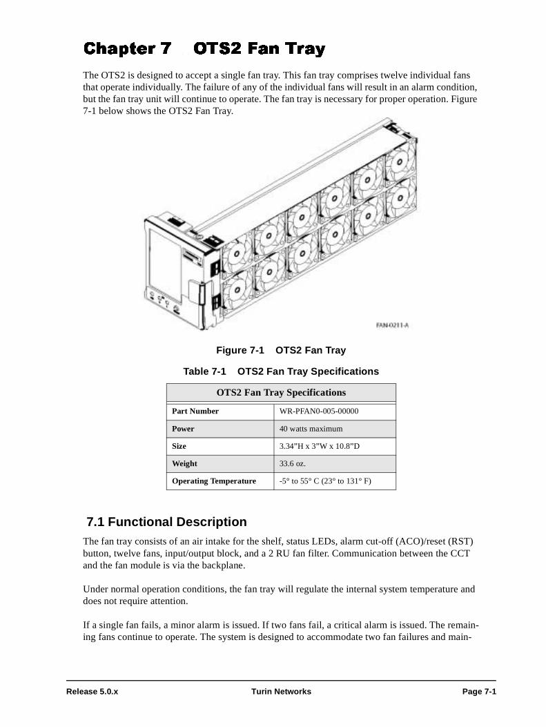
Release 5.0.x Turin Networks Page 7-1
Chapter 7 OTS2 Fan Tray
The OTS2 is designed to accept a single fan tray. This fan tray comprises twelve individual fans that operate individually. The failure of any of the individual fans will result in an alarm condition, but the fan tray unit will continue to operate. The fan tray is necessary for proper operation. Figure 7-1 below shows the OTS2 Fan Tray.
Figure 7-1 OTS2 Fan Tray
7.1 Functional DescriptionThe fan tray consists of an air intake for the shelf, status LEDs, alarm cut-off (ACO)/reset (RST) button, twelve fans, input/output block, and a 2 RU fan filter. Communication between the CCT and the fan module is via the backplane.
Under normal operation conditions, the fan tray will regulate the internal system temperature and does not require attention.
If a single fan fails, a minor alarm is issued. If two fans fail, a critical alarm is issued. The remain-ing fans continue to operate. The system is designed to accommodate two fan failures and main-
Table 7-1 OTS2 Fan Tray Specifications
OTS2 Fan Tray Specifications
Part Number WR-PFAN0-005-00000
Power 40 watts maximum
Size 3.34”H x 3”W x 10.8”D
Weight 33.6 oz.
Operating Temperature -5° to 55° C (23° to 131° F)
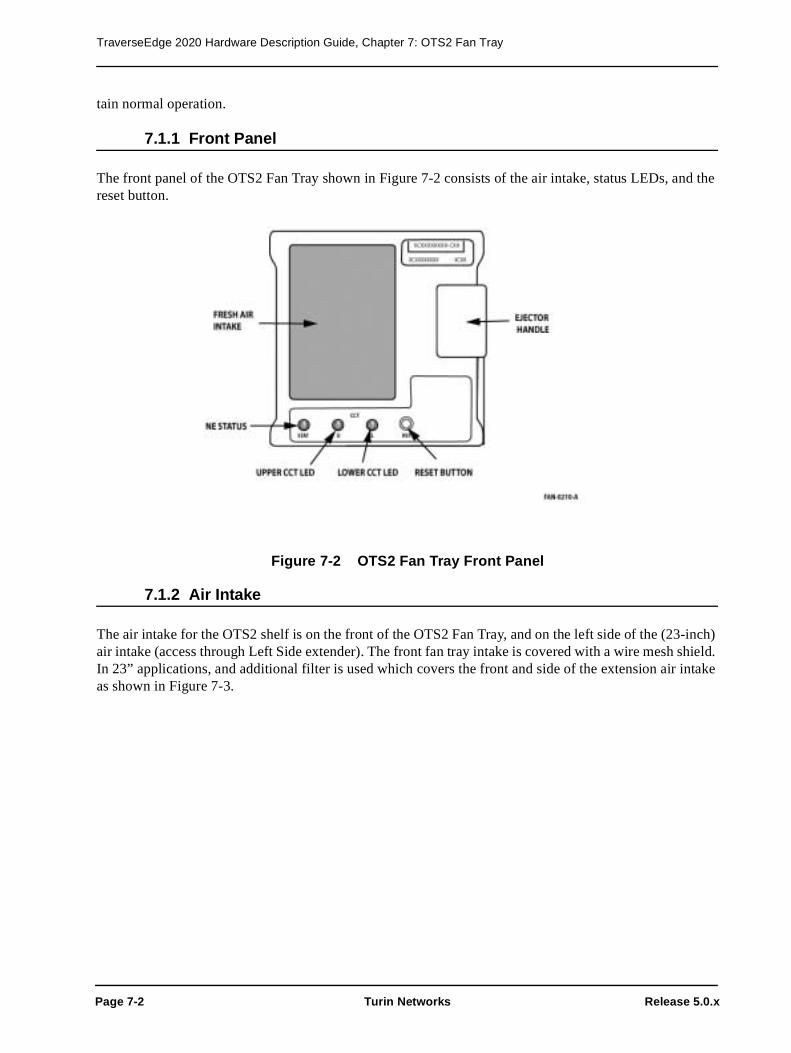
TraverseEdge 2020 Hardware Description Guide, Chapter 7: OTS2 Fan Tray
Page 7-2 Turin Networks Release 5.0.x
tain normal operation.
7.1.1 Front Panel
The front panel of the OTS2 Fan Tray shown in Figure 7-2 consists of the air intake, status LEDs, and the reset button.
Figure 7-2 OTS2 Fan Tray Front Panel
7.1.2 Air Intake
The air intake for the OTS2 shelf is on the front of the OTS2 Fan Tray, and on the left side of the (23-inch) air intake (access through Left Side extender). The front fan tray intake is covered with a wire mesh shield. In 23” applications, and additional filter is used which covers the front and side of the extension air intake as shown in Figure 7-3.

TraverseEdge 2020 Hardware Description Guide, Chapter 7: OTS2 Fan Tray
Release 5.0.x Turin Networks Page 7-3
Figure 7-3 23” Extension Filter
7.1.3 LEDs
The Fan Tray LEDs are for the Upper OTS2 CCT board (U), the Lower OTS2 CCT board (L), and the NE Status (STAT). The LEDs will be green if operations are normal. If the LEDs become red or yellow, an alarm has been issued. The alarm status colors are shown in Table 7-2 and Table 7-3 .
Table 7-2 Upper and Lower CCT Status LED Behavior
Representation LED Behavior
Critical or Major Alarm Condition on CCT Red
Minor Alarm Condition on CCT Yellow
Normal, No Alarm Conditions Green
No Power, Out of Service Off
Table 7-3 System Status LED Behavior
Representation LED Behavior
Critical or Major Alarm Condition on Shelf Red
Minor Alarm Condition on Shelf Yellow
Normal, No Alarm Conditions Green
No Power, Out of Service Off
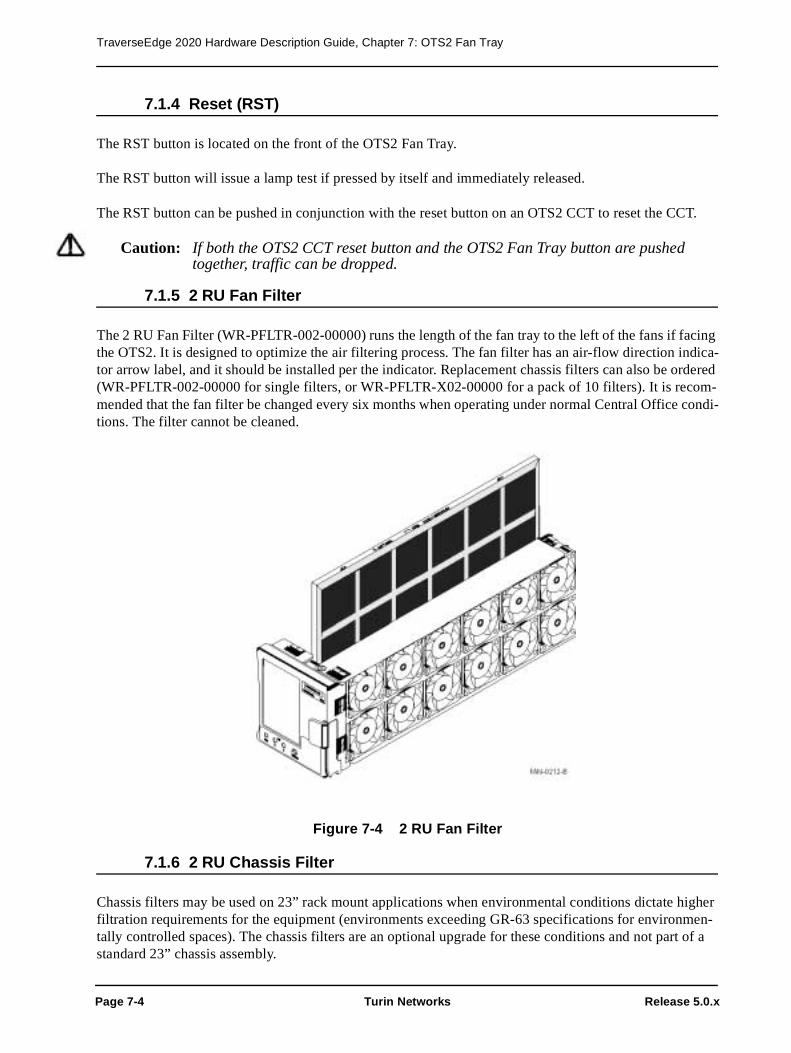
TraverseEdge 2020 Hardware Description Guide, Chapter 7: OTS2 Fan Tray
Page 7-4 Turin Networks Release 5.0.x
7.1.4 Reset (RST)
The RST button is located on the front of the OTS2 Fan Tray.
The RST button will issue a lamp test if pressed by itself and immediately released.
The RST button can be pushed in conjunction with the reset button on an OTS2 CCT to reset the CCT.
Caution: If both the OTS2 CCT reset button and the OTS2 Fan Tray button are pushed together, traffic can be dropped.
7.1.5 2 RU Fan Filter
The 2 RU Fan Filter (WR-PFLTR-002-00000) runs the length of the fan tray to the left of the fans if facing the OTS2. It is designed to optimize the air filtering process. The fan filter has an air-flow direction indica-tor arrow label, and it should be installed per the indicator. Replacement chassis filters can also be ordered (WR-PFLTR-002-00000 for single filters, or WR-PFLTR-X02-00000 for a pack of 10 filters). It is recom-mended that the fan filter be changed every six months when operating under normal Central Office condi-tions. The filter cannot be cleaned.
Figure 7-4 2 RU Fan Filter
7.1.6 2 RU Chassis Filter
Chassis filters may be used on 23” rack mount applications when environmental conditions dictate higher filtration requirements for the equipment (environments exceeding GR-63 specifications for environmen-tally controlled spaces). The chassis filters are an optional upgrade for these conditions and not part of a standard 23” chassis assembly.
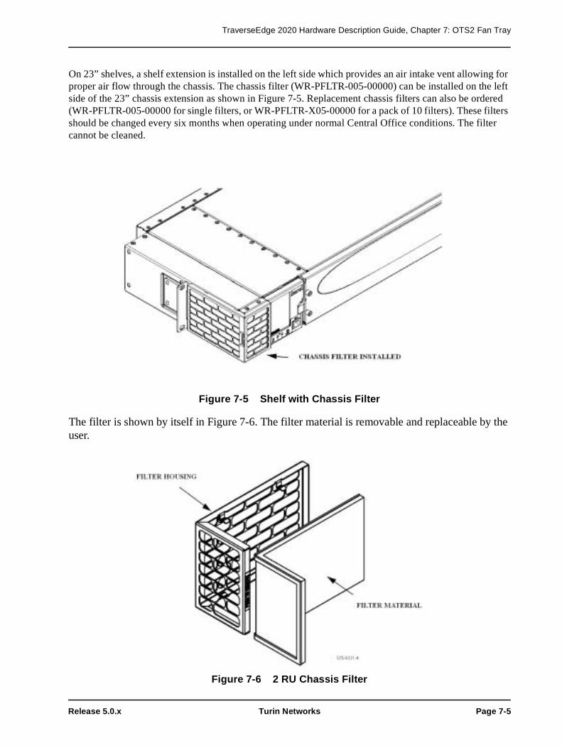
TraverseEdge 2020 Hardware Description Guide, Chapter 7: OTS2 Fan Tray
Release 5.0.x Turin Networks Page 7-5
On 23” shelves, a shelf extension is installed on the left side which provides an air intake vent allowing for proper air flow through the chassis. The chassis filter (WR-PFLTR-005-00000) can be installed on the left side of the 23” chassis extension as shown in Figure 7-5. Replacement chassis filters can also be ordered (WR-PFLTR-005-00000 for single filters, or WR-PFLTR-X05-00000 for a pack of 10 filters). These filters should be changed every six months when operating under normal Central Office conditions. The filter cannot be cleaned.
Figure 7-5 Shelf with Chassis Filter
The filter is shown by itself in Figure 7-6. The filter material is removable and replaceable by the user.
Figure 7-6 2 RU Chassis Filter

TraverseEdge 2020 Hardware Description Guide, Chapter 7: OTS2 Fan Tray
Page 7-6 Turin Networks Release 5.0.x
Release 5.0.x Turin Networks Page 8-1
Chapter 8 DS3/EC1 Tributary Shelf(ETS1)
The DS3/EC1 Tributary Shelf (ETS1) is a three rack unit (RU) tall chassis that comes in sizes to fit both 19-inch and 23-inch rack applications. The additional plug-in units that can be installed within the shelf are the Fan Tray, CCTs, and DS3/EC1 PLMs. The shelf provides the following features:
• Backplane• Fan Tray Slot
• DS3/EC1 CCT slots - Left and Right• DS3 1:n Protection
• DS3/EC1 PLM Slots• LEI Connectors
• Power and Ground Connectors• Mounting Brackets
• Front Cover
8.1 DS3/EC1 Tributary Shelf (ETS1) - 19"
The DS3/EC1 Tributary Shelf - 19" is used with the TE-2020 Main Shelf to provide electrical interfaces. The ETS1 is built on a horizontal, 3 RU architecture. The front and rear of the 19" -ETS1 are shown in Figure 8-1 and Figure 8-2.
Table 8-1 19" ETS1 Specifications
19” ETS1 Specifications
Part Number WR-TDS30-001-00000
Voltage -42.5Vdc to -56.5Vdc
Size 5.25”H x17.72”W x12.0” D
Weight 15 lbs
Operating Temperature -5° to 55° C (23° to 131° F)

TraverseEdge 2020 Hardware Description Guide, Chapter 8: DS3/EC1 Tributary Shelf (ETS1)
Page 8-2 Turin Networks Release 5.0.x
Figure 8-1 19" ETS1
Figure 8-2 19” ETS1 Backplane
Fan TraySlot
CCT Slots
PLM Slots
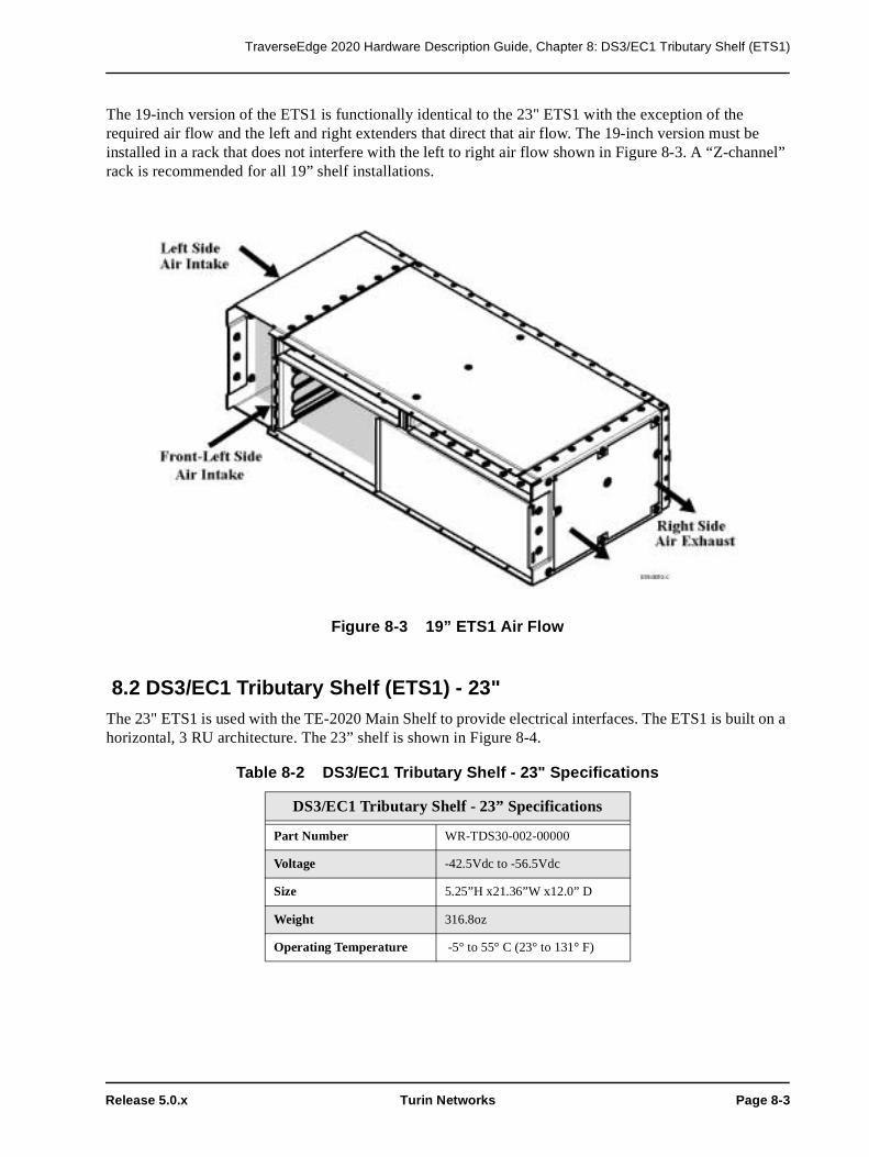
TraverseEdge 2020 Hardware Description Guide, Chapter 8: DS3/EC1 Tributary Shelf (ETS1)
Release 5.0.x Turin Networks Page 8-3
The 19-inch version of the ETS1 is functionally identical to the 23" ETS1 with the exception of the required air flow and the left and right extenders that direct that air flow. The 19-inch version must be installed in a rack that does not interfere with the left to right air flow shown in Figure 8-3. A “Z-channel” rack is recommended for all 19” shelf installations.
Figure 8-3 19” ETS1 Air Flow
8.2 DS3/EC1 Tributary Shelf (ETS1) - 23"The 23" ETS1 is used with the TE-2020 Main Shelf to provide electrical interfaces. The ETS1 is built on a horizontal, 3 RU architecture. The 23” shelf is shown in Figure 8-4.
Table 8-2 DS3/EC1 Tributary Shelf - 23" Specifications
DS3/EC1 Tributary Shelf - 23” Specifications
Part Number WR-TDS30-002-00000
Voltage -42.5Vdc to -56.5Vdc
Size 5.25”H x21.36”W x12.0” D
Weight 316.8oz
Operating Temperature -5° to 55° C (23° to 131° F)
TraverseEdge 2020 Hardware Description Guide, Chapter 8: DS3/EC1 Tributary Shelf (ETS1)
Page 8-4 Turin Networks Release 5.0.x
Figure 8-4 ETS1 - 23"
Figure 8-5 ETS1 - 23” Backplane

TraverseEdge 2020 Hardware Description Guide, Chapter 8: DS3/EC1 Tributary Shelf (ETS1)
Release 5.0.x Turin Networks Page 8-5
The 23-inch ETS1 is functionally identical to the 19-inch shelf with the exception of the required air flow. Baffles are installed on either side of the shelf that redirect the airflow out the back side. The 23” version must be installed in a rack that does not interfere with the front to right back air flow shown in Figure 8-6.
NOTE: 23-inch ETS1 shelves cannot be converted to 19-inch shelves.
Figure 8-6 ETS1 - 23” Air Flow
8.3 Power Supply and ReturnThe ETS1 provides redundant (A and B) -48 Vdc power connectors to supply power to the system. Each connector has a removable plug to aid in the installation of Supply and Return wires. The A connector is labeled -48A for Supply and RTN for Return. The B connector is labeled -48B for Supply and RTN for Return. These connectors are illustrated in Figure 8-7.

TraverseEdge 2020 Hardware Description Guide, Chapter 8: DS3/EC1 Tributary Shelf (ETS1)
Page 8-6 Turin Networks Release 5.0.x
Figure 8-7 A and B Power Connectors
The maximum, minimum, and nominal input voltages (as measured across -48 and RTN) are shown in Table 8-3 .
8.4 Frame GroundThe ETS1 provides a Frame Ground connection on the back of the shelf. The Frame Ground should be connected to the Frame or Chassis Ground for the bay.
8.5 BackplaneThe ETS1 has a three rack unit backplane that provides connectivity between the CCTs, power distribution for all of the shelf plug-ins, DS3/EC-1 interfaces through the BNC I/O backplane, and LEI access.
8.6 LEI ConnectionThe ETS1 provides connectivity for a single LEI connection pair to provide Data and Management com-munication with the TE-2020 Main Shelf.
It takes a pair of LEI cables to create a fully redundant link between the TE-2020 Main Shelf and a tribu-tary shelf. There are two types of LEI cables (A and B) that make up a complete LEI connection pair. Each LEI A connector on the shelf has a female DB-15 connector which allows only an LEI A cable equipped
Table 8-3 -48V Supply and Return Specification
Power Minimum (Vdc)
Nominal (Vdc)
Maximum (Vdc)
A -42.5 -48 -56.5
B -42.5 -48 -56.5

TraverseEdge 2020 Hardware Description Guide, Chapter 8: DS3/EC1 Tributary Shelf (ETS1)
Release 5.0.x Turin Networks Page 8-7
with a male end to be connected to it. Each LEI B connector on the shelf has a male DB-15 connector which allows only a female connector on the LEI B cable to be connected to it.
8.7 1:n ProtectionThe PLM cards must be populated from top to bottom in the shelf. If utilized, the protect card is in the top slot with the other cards in each of the next slots. The cards must be installed in adjacent slots. If a slot is left empty, the next lower slot will be unprotected. Refer to Figure 8-8 for slot identification.If a Transmux PLM is used, a Transmux PLM must also be used in the protect slot. The Transmux PLM can be used to protect both the DS3/EC-1 PLM and Transmux PLMs.
Figure 8-8 ETS1 Protection Scheme
8.8 Front CoverThe Front Cover is designed to cover the port level LEDs and to give the installation a neat appearance.
NOTE: Special care is advised when removing the cover. The user must hold the cover securely to prevent dropping.
TraverseEdge 2020 Hardware Description Guide, Chapter 8: DS3/EC1 Tributary Shelf (ETS1)
Page 8-8 Turin Networks Release 5.0.x
Figure 8-9 Installing ETS1 Front Cover

Release 5.0.x Turin Networks Page 9-1
Chapter 9 DS3/EC1 Tributary (ETS1) CCT
The DS3/EC1 Tributary Shelf (ETS1) Common Control and Timing (CCT) card, illustrated in Figure 9-1, is designed for installation in the ETS1.
Figure 9-1 ETS1 CCT
9.1 ConfigurationsThe CCT supports the configurations below. Consult the TE-2020 Applications and Engineering Manual (WR-D2020-APP-040000) for configuration details.
• 1+1 Protected
9.2 Physical SpecificationsThe ETS1 CCT provides the power, synchronization, processor and SONET/SDH mapping functions for the ETS1. For each ETS1 there are two ETS1 CCTs installed for protected operation. Each CCT can be individually installed and removed with the system operational. If only one CCT is installed, the ETS1 fea-tures do not have a redundant backup. Specifications are listed in Table 9-1 .
Table 9-1 ETS1 CCT Specifications
ETS1 CCT Specifications
Part Number WR-PCCT0-002-00000
Power 25 watts maximum
Size 1”H x 7.25”W x 7.25”D
Weight 38.4oz
Operating Temperature -5° to 55° C (23° to 131° F)
TraverseEdge 2020 Hardware Description Guide, Chapter 9: DS3/EC1 Tributary (ETS1) CCT
Page 9-2 Turin Networks Release 5.0.x
9.3 Functional DescriptionThe ETS1 contains two ETS1 CCT cards, one DS3/EC1 PLM for protection, and four DS3/EC1 PLMs for working traffic. The CCT performs the following functions:
• Control of the Shelf
- Power selection/conversion
- Microprocessor core
- Software storage and upgrade
- Temperature monitoring
- Reset control
- Protection switching for failure conditions
• SONET Mapping• LEI Termination and Protection
• Communication with the Main Shelf
For each ETS1 there are two ETS1 CCTs installed for protected operation. Each ETS1 CCT can be installed and removed with the system operational making the ETS1 fully redundant.
9.3.1 Power Selection/Conversion
The CCT accepts redundant -48Vdc nominal power inputs from the rear connectors on the backplane and shares A and B for use on the system. The selected inputs are then converted to board level voltages (i.e., +1.8Vdc, +3.3Vdc, +5Vdc) and distributed to the cards and components.
9.3.2 Microprocessor Core
The microprocessor core on the ETS1 CCT provides the necessary performance for handling the required configuration, management, routing, and real-time processing responsibilities.
9.3.3 Software Storage and Upgrade
The ETS1 CCT provides non-volatile memory for the storage of system software. The non-volatile mem-ory stores the database and current and fallback application software for the network element.
9.3.4 Temperature Monitoring
Each ETS1 CCT contains five temperature sensors on the top of the board, and three temperature sensors on the bottom of the board. The system will alarm in the event that the temperature exceeds predefined lev-els.
9.3.5 Reset Control
Each ETS1 CCT contains a reset and an enable button on the front of the card. Refer to Figure 9-2. The RST (reset) button pushed by itself has no effect on the system or card. The reset button must be pushed in conjunction with the Enable button on the CCT in order to reset the ETS1 CCT.

TraverseEdge 2020 Hardware Description Guide, Chapter 9: DS3/EC1 Tributary (ETS1) CCT
Release 5.0.x Turin Networks Page 9-3
Figure 9-2 ETS1 CCT Front Panel
9.3.6 Protection Switching
The DS3/EC1 Tributary CCT is responsible for detecting and properly switching to a redundant source for protected equipment failures within the shelf. The equipment failures can be on PLMs or on the CCTs themselves.
9.4 SONET MappingAll of the DS3/EC-1 interfaces from the various PLMs are mapped to the STS-48 of the LEI in both the transmit and receive directions. The LEI traffic will be cross-connected at the TE-2020 Main Shelf.
9.5 Local Equipment Interconnect (LEI)The ETS1 CCT has protected electrical interfaces for interconnection to the TE-2020 Main Shelf. Each LEI cable is capable of transmitting two STS-48 (2.488 Gbps) bidirectional signals for up to 10 meters. The CCT is responsible for selecting the appropriate signal to use for data and management traffic as part of the protection mechanism. The ETS1 supports a single LEI connection to the TE-2020 Main Shelf.
9.6 Backplane ConnectorsThe backplane connector on the leading edge (inserted first in the CCT slot) of the CCT provides power as well as data and management connectivity between pairs of CCTs, PLMs, and the other shelves.

TraverseEdge 2020 Hardware Description Guide, Chapter 9: DS3/EC1 Tributary (ETS1) CCT
Page 9-4 Turin Networks Release 5.0.x
TraverseEdge 2020 Hardware Description Guide, Chapter 10: ETS Fan Tray
Release 5.0.x Turin Networks Page 10-1
Chapter 10 ETS Fan Tray
The ETS1 and ETS2 are designed to accept a single fan tray. This fan tray comprises six individual fans that operate independently. The failure of any of the individual fans will result in an alarm condition, but the fan tray unit will continue to operate. The fan tray is necessary for proper operation. Figure 10-1 below illustrates the ETS1 Fan Tray.
Figure 10-1 ETS Fan Tray
The ETS Fan Tray is required in every ETS1 or ETS2. It provides the air movement needed to maintain an appropriate system temperature.
Table 10-1 ETS Fan Tray Specifications
ETS Fan Tray Specifications
Part Number WR-PFAN0-002-00000
Power 20.2 Watts
Size 5.25”H x 7.75”W x 9.0” D
Weight 27.2 oz.
Operating Temperature -5° to 55° C (23° to 131° F)
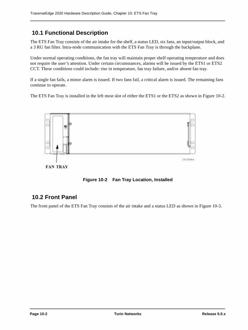
TraverseEdge 2020 Hardware Description Guide, Chapter 10: ETS Fan Tray
Page 10-2 Turin Networks Release 5.0.x
10.1 Functional DescriptionThe ETS Fan Tray consists of the air intake for the shelf, a status LED, six fans, an input/output block, and a 3 RU fan filter. Intra-node communication with the ETS Fan Tray is through the backplane.
Under normal operating conditions, the fan tray will maintain proper shelf operating temperature and does not require the user’s attention. Under certain circumstances, alarms will be issued by the ETS1 or ETS2 CCT. These conditions could include: rise in temperature, fan tray failure, and/or absent fan tray.
If a single fan fails, a minor alarm is issued. If two fans fail, a critical alarm is issued. The remaining fans continue to operate.
The ETS Fan Tray is installed in the left most slot of either the ETS1 or the ETS2 as shown in Figure 10-2.
Figure 10-2 Fan Tray Location, Installed
10.2 Front PanelThe front panel of the ETS Fan Tray consists of the air intake and a status LED as shown in Figure 10-3.

TraverseEdge 2020 Hardware Description Guide, Chapter 10: ETS Fan Tray
Release 5.0.x Turin Networks Page 10-3
Figure 10-3 ETS Fan Tray Front Panel
10.2.1 Air Intake
The air intake for the ETS1 and ETS2 is on the front of the ETS Fan Tray, and on the left side of the air intake (access through Left Side extender on 23” shelves). The front fan tray intake is covered with a wire mesh shield. In 23” applications, an additional filter is used which covers the front and side of the exten-sion air intake as shown in Figure 10-4.
Figure 10-4 23” Extension Air Filter
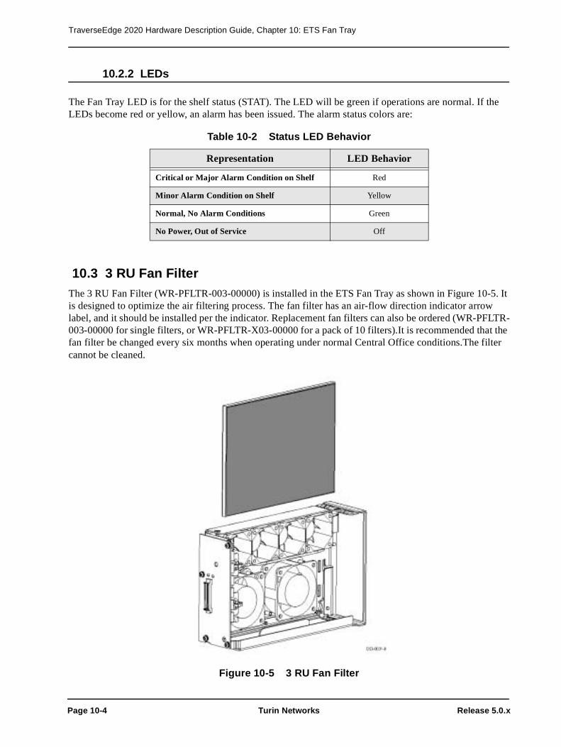
TraverseEdge 2020 Hardware Description Guide, Chapter 10: ETS Fan Tray
Page 10-4 Turin Networks Release 5.0.x
10.2.2 LEDs
The Fan Tray LED is for the shelf status (STAT). The LED will be green if operations are normal. If the LEDs become red or yellow, an alarm has been issued. The alarm status colors are:
10.3 3 RU Fan FilterThe 3 RU Fan Filter (WR-PFLTR-003-00000) is installed in the ETS Fan Tray as shown in Figure 10-5. It is designed to optimize the air filtering process. The fan filter has an air-flow direction indicator arrow label, and it should be installed per the indicator. Replacement fan filters can also be ordered (WR-PFLTR-003-00000 for single filters, or WR-PFLTR-X03-00000 for a pack of 10 filters).It is recommended that the fan filter be changed every six months when operating under normal Central Office conditions.The filter cannot be cleaned.
Figure 10-5 3 RU Fan Filter
Table 10-2 Status LED Behavior
Representation LED Behavior
Critical or Major Alarm Condition on Shelf Red
Minor Alarm Condition on Shelf Yellow
Normal, No Alarm Conditions Green
No Power, Out of Service Off

TraverseEdge 2020 Hardware Description Guide, Chapter 10: ETS Fan Tray
Release 5.0.x Turin Networks Page 10-5
10.3.1 3 RU Chassis Filter
Chassis filters may be used on 23” rack mount applications when environmental conditions dictate higher filtration requirements for the equipment (environments exceeding GR-63 specifications for environmen-tally controlled spaces). The chassis filters are an optional upgrade for these conditions and not part of a standard 23” chassis assembly.
On 23” shelves, a shelf extension is installed on the left side which provides an air intake vent allowing for proper air flow through the chassis. The chassis filter (WR-KFLTR-2RU-00000) can be installed on the left side of the 23” chassis extension as shown in Figure 10-6. Replacement chassis filters can also be ordered (WR-PFLTR-006-00000 for single filters, or WR-PFLTR-X06-00000 for a pack of 10 filters). These filters should be changed every six months when operating under normal Central Office conditions. The filter cannot be cleaned.
Figure 10-6 ETS1 Chassis Filter Installed

TraverseEdge 2020 Hardware Description Guide, Chapter 10: ETS Fan Tray
Page 10-6 Turin Networks Release 5.0.x

Release 5.0.x Turin Networks Page 11-1
Chapter 11 ETS2 Shelf
The ETS2 shelf is a three rack unit (RU) tall chassis that comes in sizes to fit both 19-inch and 23-inch rack applications. The additional plug-in units that can be installed within the shelf are the Fan Tray, CCTs, DS3/EC-1 PLMs, FastE PLMs, and DS1 PLMs. The shelf provides the following features:
• 19” or 23” Mounting Configurations• Fan Tray Slot
• ETS2 CCT slots - Left and Right• DS3/EC-1 1:1 Protection
• DS1 1:1 Protection• DS3/EC-1 or Transmux PLM Slots
• DS1 or FastE PLM Slots• LEI Connectors
• Power and Ground Connectors• Mounting Brackets
• Front Cover
11.1 ETS2 - 19"
The ETS2 - 19" shelf is used with the TE-2020 Main Shelf to provide electrical interface capabilities. The ETS2 is built on a horizontal, 3 RU architecture. The front and rear of the 19-inch shelf are shown in Figure 11-1 and Figure 11-2.
Table 11-1 ETS2 - 19" Specifications
ETS2 - 19” Specifications
Part Number WR-TETS2-001-00000
Voltage -42.5Vdc to -56.5Vdc
Size 5.25”H x17.72”W x12.0” D
Weight 225.6oz
Operating Temperature -5° to 55° C (23° to 131° F)
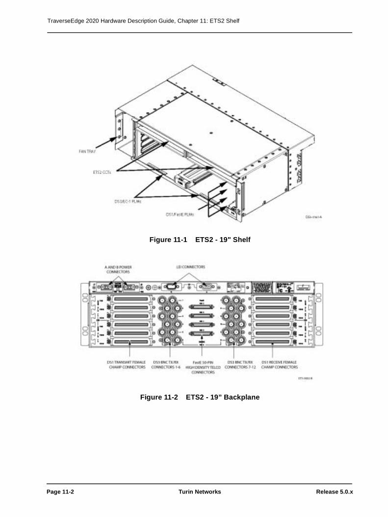
TraverseEdge 2020 Hardware Description Guide, Chapter 11: ETS2 Shelf
Page 11-2 Turin Networks Release 5.0.x
Figure 11-1 ETS2 - 19" Shelf
Figure 11-2 ETS2 - 19” Backplane
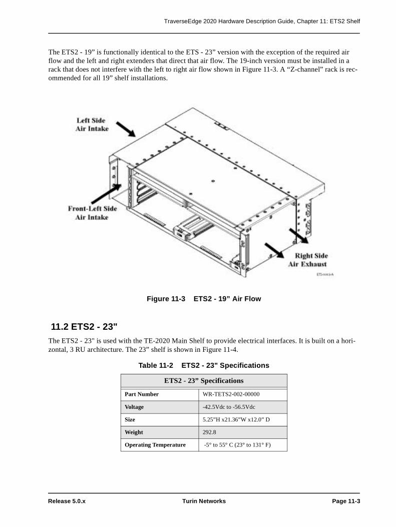
TraverseEdge 2020 Hardware Description Guide, Chapter 11: ETS2 Shelf
Release 5.0.x Turin Networks Page 11-3
The ETS2 - 19” is functionally identical to the ETS - 23” version with the exception of the required air flow and the left and right extenders that direct that air flow. The 19-inch version must be installed in a rack that does not interfere with the left to right air flow shown in Figure 11-3. A “Z-channel” rack is rec-ommended for all 19” shelf installations.
Figure 11-3 ETS2 - 19” Air Flow
11.2 ETS2 - 23"The ETS2 - 23" is used with the TE-2020 Main Shelf to provide electrical interfaces. It is built on a hori-zontal, 3 RU architecture. The 23” shelf is shown in Figure 11-4.
Table 11-2 ETS2 - 23" Specifications
ETS2 - 23” Specifications
Part Number WR-TETS2-002-00000
Voltage -42.5Vdc to -56.5Vdc
Size 5.25”H x21.36”W x12.0” D
Weight 292.8
Operating Temperature -5° to 55° C (23° to 131° F)

TraverseEdge 2020 Hardware Description Guide, Chapter 11: ETS2 Shelf
Page 11-4 Turin Networks Release 5.0.x
Figure 11-4 . ETS2 - 23"
Figure 11-5 ETS2 - 23” Backplane
The ETS2 - 23” is functionally identical to the ETS2 - 19" with the exception of the required air flow. Baf-fles are installed on either side of the shelf that redirect the airflow out the back side. The 23” version must

TraverseEdge 2020 Hardware Description Guide, Chapter 11: ETS2 Shelf
Release 5.0.x Turin Networks Page 11-5
be installed in a rack that does not interfere with the front to right back air flow shown in Figure 11-6.
NOTE: 23-inch ETS2 shelves cannot be converted to 19-inch shelves.
Figure 11-6 ETS2 - 23” Air Flow
DS3 Connections
DS3 connections are provided in the form of BNC connectors. The left group of BNC connectors (facing the rear) are ports 1-6 Transmit and Receive, the right group are ports 7-12 Transmit and Receive connec-tors. Refer to Figure 11-7.
Figure 11-7 DS3 Backplane Connections

TraverseEdge 2020 Hardware Description Guide, Chapter 11: ETS2 Shelf
Page 11-6 Turin Networks Release 5.0.x
DS1 Connections
DS1 connections are provided in the form of female 64-pin Champ connectors as shown in Figure 11-8. The female 64-pin Champ uses a shielded hood with a #4-40 screw to hold the connector to the chassis. The right group of connectors are for Receive inputs to the shelf. The left group of connectors is for Trans-mit out from the shelf. The DS1 PLMs can be utilized in a working (Row 3 or 5) and protect (Row 2 or 4) arrangement.
Figure 11-8 DS1 Backplane Connections
Each female DS1 connector handles 28 DS1 ports and is labeled F1-28, F29-56, or F57-84 for a total of 84 possible facilities on a DS1 PLM. An 84 port DS1 PLM will require 6 female backplane connectors (3 Receive plus 3 Transmit) to allow for a total 84 DS1 interfaces. For 28 port PLMs, only the first female connector for each row (i.e., ROW 2/3) will be utilized. Refer to Figure 11-9 which indicates the associa-tion between the DS1 PLMs and the female DS1 connectors on the rear of the shelf.

TraverseEdge 2020 Hardware Description Guide, Chapter 11: ETS2 Shelf
Release 5.0.x Turin Networks Page 11-7
Figure 11-9 ETS2 Backplane - DS1 PLM to Female DS1 Connector Association
Figure 11-10 below shows the port pin outs for each female DS1 connector on the backplane. Note that the female Transmit connectors on the left side of the shelf are inverted in relationship to the female Receive connectors on the right side of the shelf.
Figure 11-10 ETS2 Backplane - Female DS1 Connector Pin Outs
Table 11-3 lists port pin out information for the female DS1 connectors in Figure 11-10. Each backplane female DS1 connector handles certain ports on the DS1 PLM (F1-28 = Ports 1-28, etc.). Turin Networks has terminated and unterminated DS1 cables available for purchase. Refer to the TE-2020 Ordering Man-

TraverseEdge 2020 Hardware Description Guide, Chapter 11: ETS2 Shelf
Page 11-8 Turin Networks Release 5.0.x
ual for details (WR-D2020-ORD-04000).
Table 11-3 ETS2 Backplane - Female DS1 Connector Port Pin Outs
FastE Interface Connections
FastE connections are provided in the form of 50-pin mini-Champ connectors (also referred to as 50-pin high density connectors) in the center at the rear of the shelf. Refer to Figure 11-11. Each connector is labeled according to the row it supports at the front of the shelf. Up to four FastE PLMs may be installed in an ETS2 shelf (if not equipped with DS1 PLMs). Each FastE PLM provides access to the network for twelve FastE interfaces.
Figure 11-11 FastE Backplane Connections

TraverseEdge 2020 Hardware Description Guide, Chapter 11: ETS2 Shelf
Release 5.0.x Turin Networks Page 11-9
The top connector labeled Row 2 provides access for twelve FastE interfaces to the FastE PLM in Row 2 at the front of the shelf. The next connector is Row 3, then Row 4, and finally Row 5. Refer to Figure 11-12 which indicates the association between the FastE PLMs and the FastE connectors at the rear of the shelf
Figure 11-12 ETS2 Backplane - FastE PLM to FastE Connector Association
Note that the Row 2 and Row 3 connectors (top 2 connectors) are inverted in relationship to the Row 4 and Row 5 connectors (bottom 2 connectors) just below them. Figure 11-13 below shows the port pin outs for each connector orientation on the backplane. Table 11-4 lists port pin out information for the FastE con-nectors. Turin Networks has terminated FastE cables available for purchase. Refer to the TE-2020 Order-ing Manual for details (WR-D2020-ORD-040000).
Figure 11-13 ETS2 Backplane - FastE Connector Pin Outs
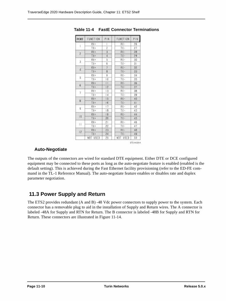
TraverseEdge 2020 Hardware Description Guide, Chapter 11: ETS2 Shelf
Page 11-10 Turin Networks Release 5.0.x
Table 11-4 FastE Connector Terminations
Auto-Negotiate
The outputs of the connectors are wired for standard DTE equipment. Either DTE or DCE configured equipment may be connected to these ports as long as the auto-negotiate feature is enabled (enabled is the default setting). This is achieved during the Fast Ethernet facility provisioning (refer to the ED-FE com-mand in the TL-1 Reference Manual). The auto-negotiate feature enables or disables rate and duplex parameter negotiation.
11.3 Power Supply and ReturnThe ETS2 provides redundant (A and B) -48 Vdc power connectors to supply power to the system. Each connector has a removable plug to aid in the installation of Supply and Return wires. The A connector is labeled -48A for Supply and RTN for Return. The B connector is labeled -48B for Supply and RTN for Return. These connectors are illustrated in Figure 11-14.
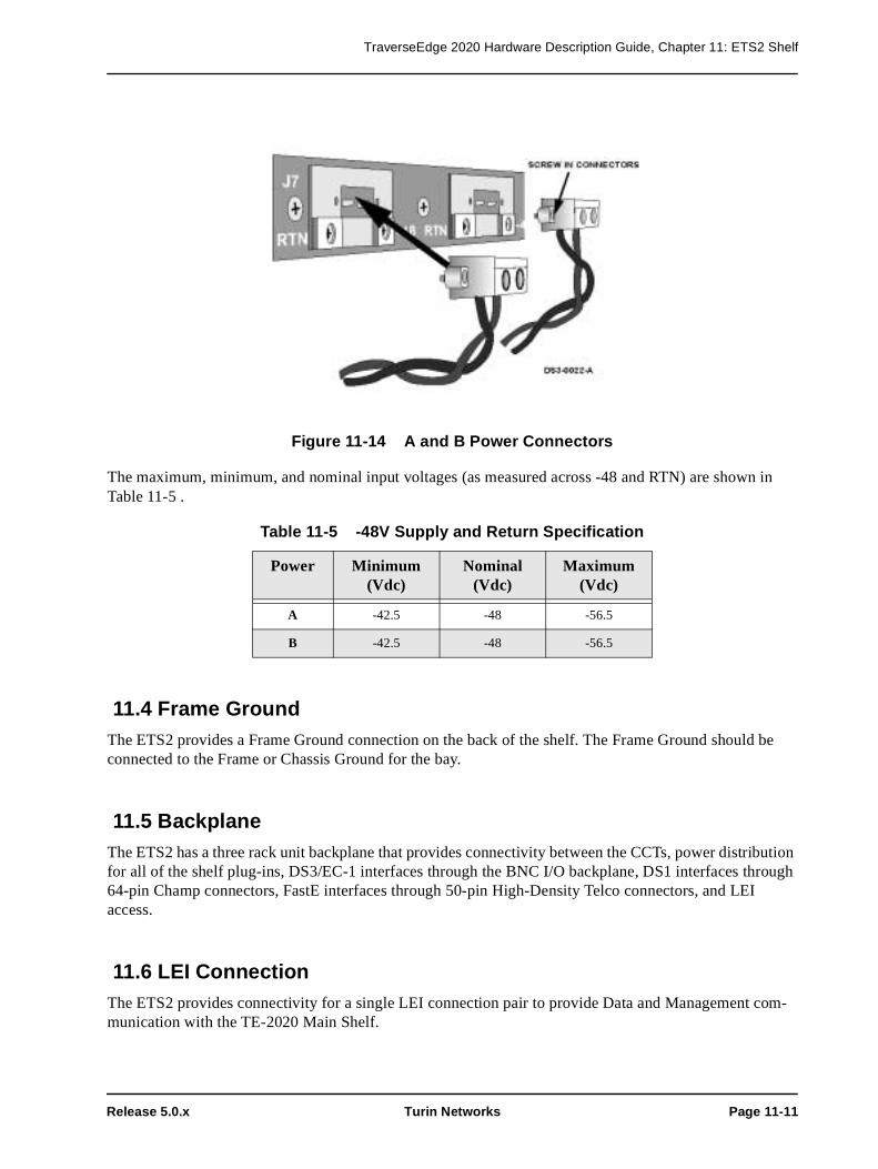
TraverseEdge 2020 Hardware Description Guide, Chapter 11: ETS2 Shelf
Release 5.0.x Turin Networks Page 11-11
Figure 11-14 A and B Power Connectors
The maximum, minimum, and nominal input voltages (as measured across -48 and RTN) are shown in Table 11-5 .
11.4 Frame GroundThe ETS2 provides a Frame Ground connection on the back of the shelf. The Frame Ground should be connected to the Frame or Chassis Ground for the bay.
11.5 BackplaneThe ETS2 has a three rack unit backplane that provides connectivity between the CCTs, power distribution for all of the shelf plug-ins, DS3/EC-1 interfaces through the BNC I/O backplane, DS1 interfaces through 64-pin Champ connectors, FastE interfaces through 50-pin High-Density Telco connectors, and LEI access.
11.6 LEI ConnectionThe ETS2 provides connectivity for a single LEI connection pair to provide Data and Management com-munication with the TE-2020 Main Shelf.
Table 11-5 -48V Supply and Return Specification
Power Minimum (Vdc)
Nominal (Vdc)
Maximum (Vdc)
A -42.5 -48 -56.5
B -42.5 -48 -56.5
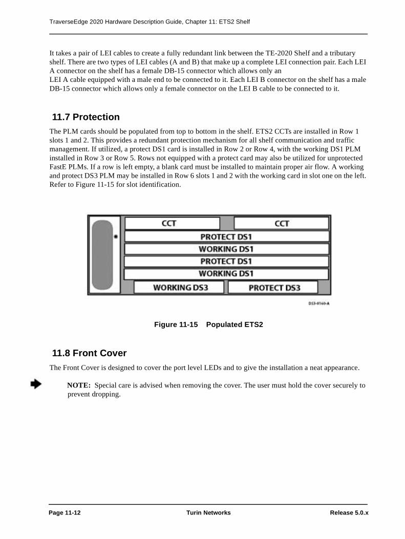
TraverseEdge 2020 Hardware Description Guide, Chapter 11: ETS2 Shelf
Page 11-12 Turin Networks Release 5.0.x
It takes a pair of LEI cables to create a fully redundant link between the TE-2020 Shelf and a tributary shelf. There are two types of LEI cables (A and B) that make up a complete LEI connection pair. Each LEI A connector on the shelf has a female DB-15 connector which allows only anLEI A cable equipped with a male end to be connected to it. Each LEI B connector on the shelf has a male DB-15 connector which allows only a female connector on the LEI B cable to be connected to it.
11.7 ProtectionThe PLM cards should be populated from top to bottom in the shelf. ETS2 CCTs are installed in Row 1 slots 1 and 2. This provides a redundant protection mechanism for all shelf communication and traffic management. If utilized, a protect DS1 card is installed in Row 2 or Row 4, with the working DS1 PLM installed in Row 3 or Row 5. Rows not equipped with a protect card may also be utilized for unprotected FastE PLMs. If a row is left empty, a blank card must be installed to maintain proper air flow. A working and protect DS3 PLM may be installed in Row 6 slots 1 and 2 with the working card in slot one on the left. Refer to Figure 11-15 for slot identification.
Figure 11-15 Populated ETS2
11.8 Front CoverThe Front Cover is designed to cover the port level LEDs and to give the installation a neat appearance.
NOTE: Special care is advised when removing the cover. The user must hold the cover securely to prevent dropping.
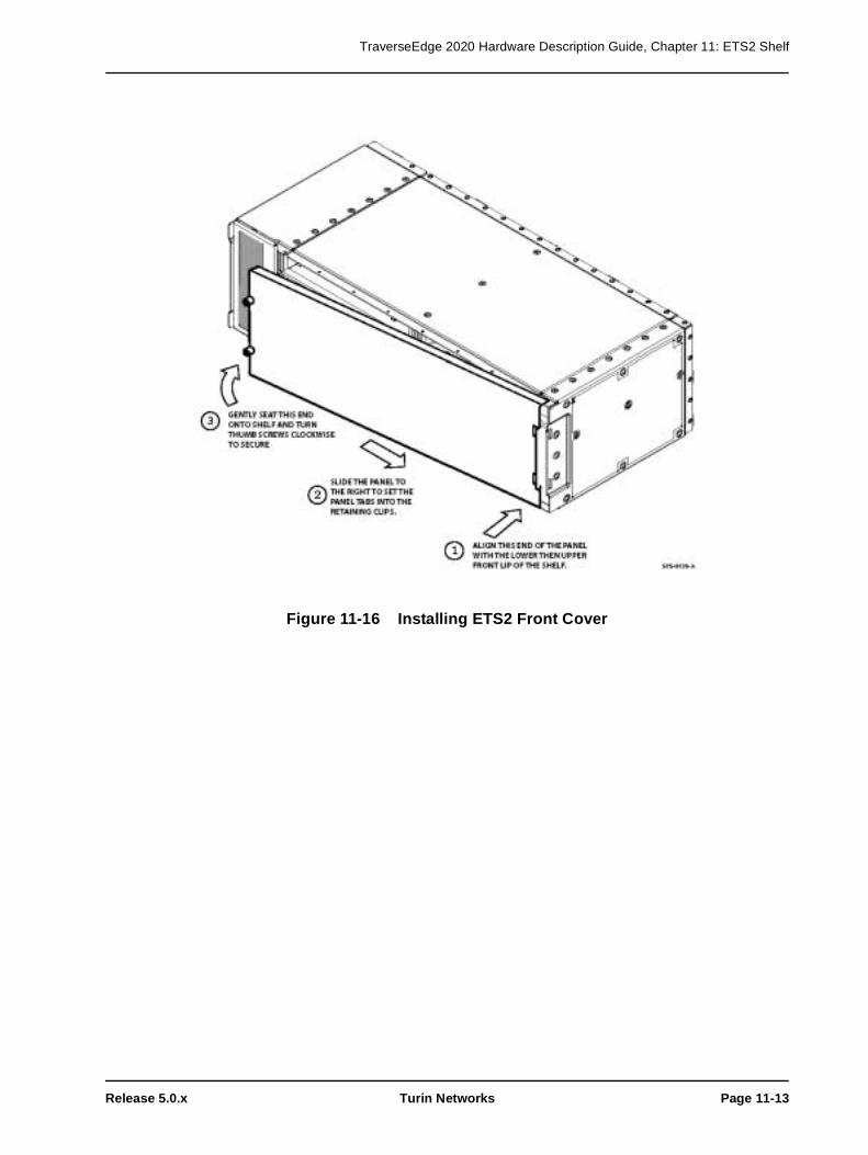
TraverseEdge 2020 Hardware Description Guide, Chapter 11: ETS2 Shelf
Release 5.0.x Turin Networks Page 11-13
Figure 11-16 Installing ETS2 Front Cover

TraverseEdge 2020 Hardware Description Guide, Chapter 11: ETS2 Shelf
Page 11-14 Turin Networks Release 5.0.x

Release 5.0.x Turin Networks Page 12-1
Chapter 12 ETS2 CCT
The ETS2 Common Control and Timing (CCT) card, illustrated in Figure 12-1, is designed for installation in the ETS2 shelf.
Figure 12-1 ETS2 CCT
12.1 ConfigurationsThe CCT supports the configurations below. Consult the TE-2020 Applications and Engineering Manual (WR-D2020-APP-040000) for configuration details.
• 1+1 Protected
12.2 Physical SpecificationsThe ETS2 CCT provides the power, synchronization, processor and SONET/SDH mapping functions for the ETS2. For each ETS2, there are two ETS2 CCTs installed for protected operation. Each CCT can be individually installed and removed with the system operational. If only one CCT is installed, the ETS2 fea-
tures do not have a redundant backup. Specifications are listed in Table 12-1 .
Table 12-1 ETS2 CCT Specifications
ETS2 CCT Specifications
Part Number WR-PCCT0-006-00000
Power 25 watts maximum

TraverseEdge 2020 Hardware Description Guide, Chapter 12: ETS2 CCT
Page 12-2 Turin Networks Release 5.0.x
12.3 Functional DescriptionThe ETS2 may contain two ETS2 CCT cards, two DS3/EC1 PLMs, and up to four DS1 PLMs (2 working/ 2 protect) or FastE PLMs (unprotected). The CCT performs the following functions:
• Control of the Shelf
- Power selection/conversion
- Microprocessor core
- Software storage and upgrade
- Temperature monitoring
- Reset control
- Protection switching for failure conditions• SONET Mapping
• LEI Termination and Protection• Communication with the Main Shelf
For each ETS2 there are two ETS2 CCTs installed for protected operation. Each CCT can be installed and removed with the system operational making the ETS2 fully redundant.
12.3.1 Power Selection/Conversion
The CCT accepts redundant -48Vdc nominal power inputs from the rear connectors on the backplane and shares A and B for use on the system. The selected inputs are then converted to board level voltages (i.e., +1.8Vdc, +3.3Vdc, +5Vdc) and distributed to the cards and components.
12.3.2 Microprocessor Core
The microprocessor core on the ETS2 CCT provides the necessary performance for handling the required configuration, management, routing, and real-time processing responsibilities.
12.3.3 Temperature Monitoring
Each ETS2 CCT contains five temperature sensors on the top of the board, and three temperature sensors on the bottom of the board. The system will alarm in the event that the temperature exceeds predefined lev-els.
12.3.4 Reset Control
Size 1”H x 7.25”W x 7.25”D
Weight 38.4oz.
Operating Temperature -5° to 55° C (23° to 131° F)
Table 12-1 ETS2 CCT Specifications
ETS2 CCT Specifications

TraverseEdge 2020 Hardware Description Guide, Chapter 12: ETS2 CCT
Release 5.0.x Turin Networks Page 12-3
Each ETS2 CCT contains a reset and an enable button on the front of the card. Refer to Figure 12-2. The RST (reset) button pushed by itself has no effect on the system or card. The reset button must be pushed in conjunction with the Enable button on the CCT in order to reset the ETS2 CCT.
Figure 12-2 ETS2 CCT Front Panel
12.3.5 Protection Switching
The ETS2 CCT is responsible for detecting and properly switching to a redundant source for protected equipment failures within the shelf. The equipment failures can be on PLMs or on the CCTs themselves.
12.4 SONET MappingAll of the interfaces from the various PLMs are mapped to the STS-48 of the LEI in both the transmit and receive directions. The LEI traffic will be cross-connected at the TE-2020 Main Shelf.
12.5 Local Equipment Interconnect (LEI)The ETS2 CCT has protected electrical interfaces for interconnection to the TE-2020 Main Shelf. Each LEI cable is capable of transmitting two STS-48 (2.488 Gbps) bidirectional signals for up to 10 meters. The CCT is responsible for selecting the appropriate signal to use for data and management traffic as part of the protection mechanism.
12.6 Backplane ConnectorsThe backplane connector on the leading edge of the CCT (inserted first in the CCT slot) provides power as well as data and management connectivity between pairs of CCTs, PLMs and the other shelves.

TraverseEdge 2020 Hardware Description Guide, Chapter 12: ETS2 CCT
Page 12-4 Turin Networks Release 5.0.x

TraverseEdge 2020 Hardware Description Guide, Chapter 13: OC-192 Physical Layer Modules
Release 5.0.x Turin Networks Page 13-1
Chapter 13 OC-192 Physical Layer Modules
The OC-192 Physical Layer Module (PLM) is a single port transmit and receive plug-in module that can only be used in the 2 slots on the lowest row of the TE-2020 Main Shelf. The OC-192 PLMs provide the following functionality and connectivity:
• Single port OC-192 optical user interface
• SR (Short Reach), IR (Intermediate Reach), LR (Long Reach), and DWDM (ITU)• Individual Transmit and Receive SC connectors
• Ejector handles for card installation and removal• Two LEDs to indicate Card and Port Status
• SONET framing functions• O/E and E/O conversion
• Clock recovery and clock generation
Figure 13-1 OC-192 x1 PLM
13.1 ConfigurationsThe OC-192 PLM can be configured to support the configurations below. Consult the TE-2020 Applica-tions and Engineering Manual (WR-D2020-APP-040000) for details.
• Unprotected• 1+1 Protected
• UPSR• 2-Fiber BLSR

TraverseEdge 2020 Hardware Description Guide, Chapter 13: OC-192 Physical Layer Modules
Page 13-2 Turin Networks Release 5.0.x
13.2 Physical SpecificationsThe OC-192 x1 PLM is available in Short Reach (SR), Intermediate Reach (IR), and Long Reach (LR) as well as ITU LR and ULR versions, all of which have Single Mode Fiber connectors. Table 13-1 through Table 13-4 provide the Physical Specifications for each type of OC-192 PLM.
Table 13-1 OC-192 x1 PLM, SR 1310 Physical Specifications
OC-192 x1 PLM, SR Physical Specifications
Part Number WR-19201-S01-31000
Power 37 watts maximum
Size 1.0”H x 6.9”W x 10.9”D
Weight 32 oz.
Operating Temperature -5° to 55° C (23° to 131° F)
Table 13-2 OC-192 x1 PLM, IR 1550 Physical Specifications
OC-192 x1 PLM, IR-2 Physical Specifications
Part Number WR-19201-I01-55000
Power 39 watts maximum
Size 1.0”H x 6.9”W x 10.9”D
Weight 32 oz.
Operating Temperature -5° to 55° C (23° to 131° F)
Table 13-3 OC-192 x1 PLM, LR 1550 Physical Specifications
OC-192 x1 PLM, LR-2 Physical Specifications
Part Number WR-19201-L01-55000
Power 45 watts maximum
Size 1.0”H x 6.9”W x 10.9”D
Weight 32 oz.
Operating Temperature -5° to 55° C (23° to 131° F)
Table 13-4 OC-192 x1 50GHz Widely Tunable PLMs
Name Part Number Description
OC-192 x1 50GHz Widely Tunable LR PLM
WR-19201-T0W-5287701 OC-192 1 Port PLM 88 Channel Tunable Long Reach Transmitter (1528.77nm to 1563.45nm), intended for single span applications
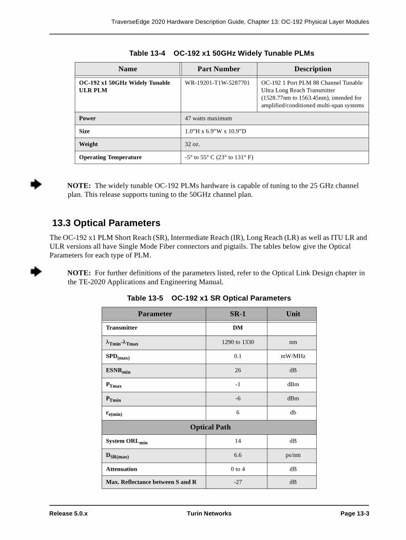
TraverseEdge 2020 Hardware Description Guide, Chapter 13: OC-192 Physical Layer Modules
Release 5.0.x Turin Networks Page 13-3
NOTE: The widely tunable OC-192 PLMs hardware is capable of tuning to the 25 GHz channel plan. This release supports tuning to the 50GHz channel plan.
13.3 Optical ParametersThe OC-192 x1 PLM Short Reach (SR), Intermediate Reach (IR), Long Reach (LR) as well as ITU LR and ULR versions all have Single Mode Fiber connectors and pigtails. The tables below give the Optical Parameters for each type of PLM.
NOTE: For further definitions of the parameters listed, refer to the Optical Link Design chapter in the TE-2020 Applications and Engineering Manual.
OC-192 x1 50GHz Widely Tunable ULR PLM
WR-19201-T1W-5287701 OC-192 1 Port PLM 88 Channel Tunable Ultra Long Reach Transmitter (1528.77nm to 1563.45nm), intended for amplified/conditioned multi-span systems
Power 47 watts maximum
Size 1.0”H x 6.9”W x 10.9”D
Weight 32 oz.
Operating Temperature -5° to 55° C (23° to 131° F)
Table 13-5 OC-192 x1 SR Optical Parameters
Parameter SR-1 Unit
Transmitter DM
λTmin-λTmax 1290 to 1330 nm
SPD(max) 0.1 mW/MHz
ESNRmin 26 dB
PTmax -1 dBm
PTmin -6 dBm
re(min) 6 db
Optical Path
System ORLmin 14 dB
DSR(max) 6.6 ps/nm
Attenuation 0 to 4 dB
Max. Reflectance between S and R -27 dB
Table 13-4 OC-192 x1 50GHz Widely Tunable PLMs
Name Part Number Description

TraverseEdge 2020 Hardware Description Guide, Chapter 13: OC-192 Physical Layer Modules
Page 13-4 Turin Networks Release 5.0.x
Receiver
PRmax -1 dBm
PRmin -11 dBm
PO 1 dB
Receiver Reflectance (max) -14 dB
Table 13-6 OC-192 x1 IR Optical Parameters
Parameter IR-2 Unit
Transmitter EM
λTmin-λTmax 1530 to 1565 nm
SPD(max) 0.1 mW/MHz
ESNRmin 26 dB
PTmax +2 dBm
PTmin -1 dBm
re(min) 8.2 db
Optical Path
System ORLmin 24 dB
DSR(max) NA to 800 ps/nm
Attenuation 3 to 11 dB
Max. Reflectance between S and R -27 dB
DGD (max) 30 ps
Receiver
PRmax -1 dBm
PRmin -14 dBm
PO 2 dB
Receiver Reflectance (max) -27 dB
Table 13-5 OC-192 x1 SR Optical Parameters
Parameter SR-1 Unit

TraverseEdge 2020 Hardware Description Guide, Chapter 13: OC-192 Physical Layer Modules
Release 5.0.x Turin Networks Page 13-5
Table 13-8. OC-192 ITU LR Optical Parameters
Table 13-7 OC-192 x1 LR Optical Parameters
Parameter LR-2 Unit
Transmitter EM
λTmin-λTmax 1530 to 1565 nm
SPD(max) 0.1 mW/MHz
OSNR(min) FFS db
PTmax +2 dBm
PTmin -2 dBm
re(min) 10 db
Optical Path
System ORLmin 24 dB
DSR(max) FFS - 1600 ps/nm
Attenuation 11 to 22 dB
Max. Reflectance between S and R -27 dB
DGD (max) 30 ps
Receiver
PRmax -9 dBm
PRmin -26 dBm
PO 2 dB
Receiver Reflectance (max) -27 dB
Parameter ITU Unit
Transmitter EM
λTmin-λTmax 1528.77 to 1563.45 nm
SPD(max) 0.1 mW/MHz
PTmax +7 dBm
PTmin +4 dBm
re(min) 10 dB
Optical Path
System ORLmin 24 dB
DSR(max) 1600 ps/nm

TraverseEdge 2020 Hardware Description Guide, Chapter 13: OC-192 Physical Layer Modules
Page 13-6 Turin Networks Release 5.0.x
Table 13-9. OC-192 ITU ULR Optical Parameters
The OC-192 ITU PLMs (both LR and ULR) are tunable (under system software control) to any one of 88 channels in the C-band. See Table 13-10 for a list of selectable wavelengths.
Max. Reflectance between S and R -27 dB
DGD (max) 30 ps
Receiver
PRmax -5 dBm
PRmin -24 dBm
PO 2 dB
Receiver Reflectance (max) -27 dB
Parameter ITU Unit
Transmitter EM
λTmin-λTmax 1528.77 to 1563.45 nm
SPD(max) 0.1 mW/MHz
PTmax +7 dBm
PTmin +4 dBm
re(min) 10 dB
Optical Path
System ORLmin 24 dB
DSR(max) 1600 ps/nm
Max. Reflectance between S and R -27 dB
DGD (max) 30 ps
Receiver
PRmax -1 dBm
PRmin -17 dBm
PO 2 dB
Receiver Reflectance (max) -27 dB
Table 13-10 OC-192 ITU Tunable Wavelengths
Tunable Wavelengths (nm)
1528.77 1529.16 1529.55 1529.94 1530.33 1530.72 1531.12 1531.51
Parameter ITU Unit
Transmitter EM
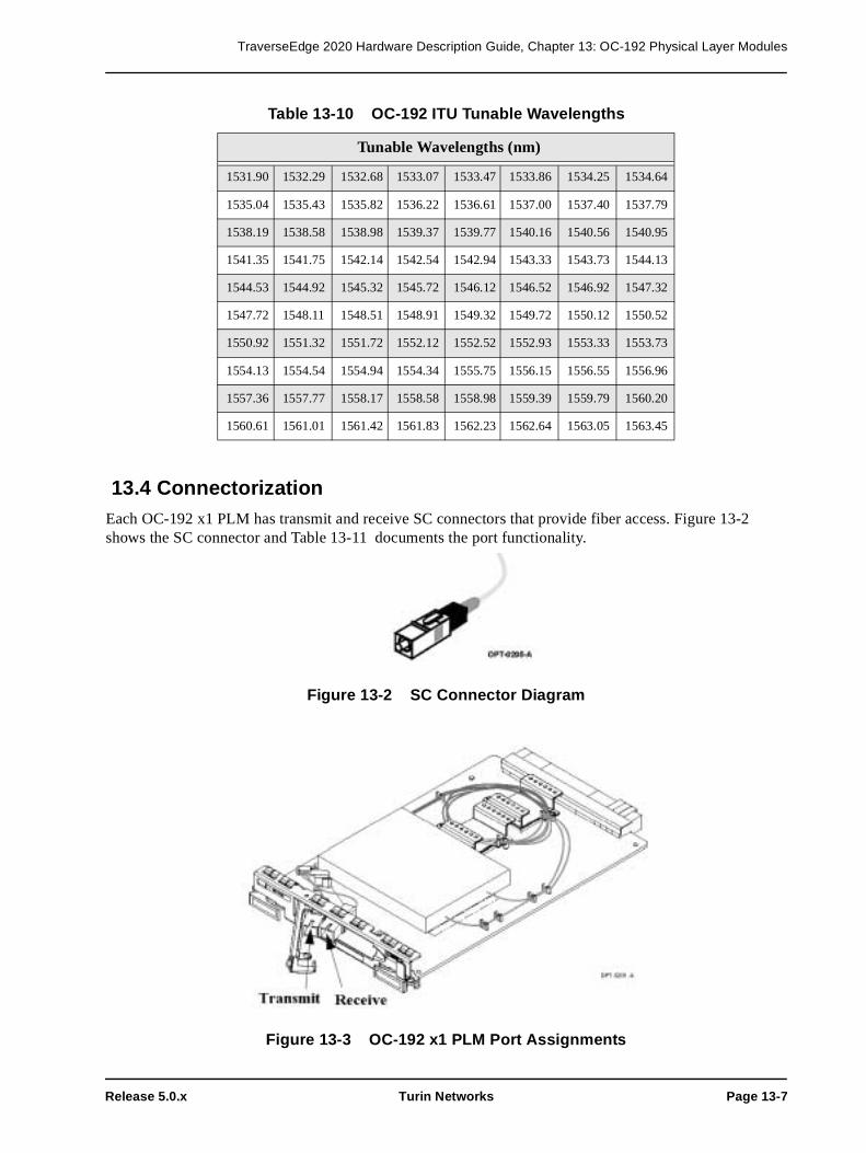
TraverseEdge 2020 Hardware Description Guide, Chapter 13: OC-192 Physical Layer Modules
Release 5.0.x Turin Networks Page 13-7
13.4 ConnectorizationEach OC-192 x1 PLM has transmit and receive SC connectors that provide fiber access. Figure 13-2 shows the SC connector and Table 13-11 documents the port functionality.
Figure 13-2 SC Connector Diagram
Figure 13-3 OC-192 x1 PLM Port Assignments
1531.90 1532.29 1532.68 1533.07 1533.47 1533.86 1534.25 1534.64
1535.04 1535.43 1535.82 1536.22 1536.61 1537.00 1537.40 1537.79
1538.19 1538.58 1538.98 1539.37 1539.77 1540.16 1540.56 1540.95
1541.35 1541.75 1542.14 1542.54 1542.94 1543.33 1543.73 1544.13
1544.53 1544.92 1545.32 1545.72 1546.12 1546.52 1546.92 1547.32
1547.72 1548.11 1548.51 1548.91 1549.32 1549.72 1550.12 1550.52
1550.92 1551.32 1551.72 1552.12 1552.52 1552.93 1553.33 1553.73
1554.13 1554.54 1554.94 1554.34 1555.75 1556.15 1556.55 1556.96
1557.36 1557.77 1558.17 1558.58 1558.98 1559.39 1559.79 1560.20
1560.61 1561.01 1561.42 1561.83 1562.23 1562.64 1563.05 1563.45
Table 13-10 OC-192 ITU Tunable Wavelengths
Tunable Wavelengths (nm)

TraverseEdge 2020 Hardware Description Guide, Chapter 13: OC-192 Physical Layer Modules
Page 13-8 Turin Networks Release 5.0.x
13.5 LED IndicatorsAn OC-192 x1 PLM has two LEDs on the front panel. The first LED shows the status of the PLM card. The remaining LED shows the status of the port. The LEDs will be green if operations are normal. If the LEDs become red or yellow, there is an alarm condition present on either the corresponding PLM or port. The alarm status colors are defined in Table 13-12 , and Table 13-13 .
Table 13-11 SC Fiber to Facility Mapping
Facility Fiber Connector Position
Port 1 - Receive Inside Fiber (right connector)
Port 1 - Transmit Outside Fiber (left connector)
Table 13-12 Port LED Behavior
Representation Port LED Behavior
Critical or Major Alarm Condition Red
Minor Alarm Condition Yellow
Loopback Flashing Yellow
Normal, No Alarm Conditions Green
No Power, Out-of-Service Off
Table 13-13 PLM Status LED Behavior
Representation Status LED Behavior
Board Failure Red
Normal Green
No Power, Out-of-Service Off
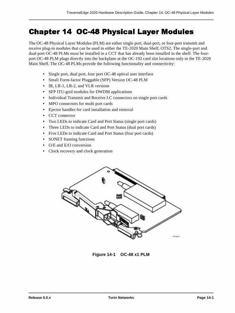
TraverseEdge 2020 Hardware Description Guide, Chapter 14: OC-48 Physical Layer Modules
Release 5.0.x Turin Networks Page 14-1
Chapter 14 OC-48 Physical Layer Modules
The OC-48 Physical Layer Modules (PLM) are either single port, dual-port, or four-port transmit and receive plug-in modules that can be used in either the TE-2020 Main Shelf, OTS2. The single-port and dual-port OC-48 PLMs must be installed in a CCT that has already been installed in the shelf. The four-port OC-48 PLM plugs directly into the backplane at the OC-192 card slot locations only in the TE-2020 Main Shelf. The OC-48 PLMs provide the following functionality and connectivity:
• Single port, dual port, four port OC-48 optical user interface• Small Form-factor Pluggable (SFP) Version OC-48 PLM
• IR, LR-1, LR-2, and VLR versions• SFP ITU-grid modules for DWDM applications
• Individual Transmit and Receive LC connectors on single port cards• MPO connectors for multi port cards
• Ejector handles for card installation and removal• CCT connector
• Two LEDs to indicate Card and Port Status (single port cards)• Three LEDs to indicate Card and Port Status (dual port cards)
• Five LEDs to indicate Card and Port Status (four port cards)• SONET framing functions
• O/E and E/O conversion• Clock recovery and clock generation
Figure 14-1 OC-48 x1 PLM

TraverseEdge 2020 Hardware Description Guide, Chapter 14: OC-48 Physical Layer Modules
Page 14-2 Turin Networks Release 5.0.x
.
Figure 14-2 OC-48 x2 PLM MPO Port
.
Figure 14-3 OC-48 x1 SFP Base PLM

TraverseEdge 2020 Hardware Description Guide, Chapter 14: OC-48 Physical Layer Modules
Release 5.0.x Turin Networks Page 14-3
Figure 14-4 OC-48 x4 PLM
14.1 ConfigurationsThe OC-48 PLMs can be configured to support the configurations below. Consult the TE-2020 Applica-tions and Engineering Manual (WR-D2020-APP-040000) for configuration details.
• Unprotected• 1+1 Protected
• UPSR• 2-Fiber BLSR
14.2 Physical SpecificationsThe OC-48 PLMs are available in an Intermediate Reach (IR) version, two Long Reach (LR) versions, and one Very Long Reach (VR-1) version all of which have Single Mode Fiber connectors. Refer to the follow-ing sections for specifications on each type of PLM.
14.2.1 Single Port OC-48 PLMs
Table 14-1 OC-48 x1 PLM, IR Physical Specifications
OC-48 x1 PLM, IR Physical Specifications
Part Number WR-04801-I01-31000
Power 12 watts maximum
Size .75”H x 3.5”W x 6”D
Weight 9.6 oz.
TraverseEdge 2020 Hardware Description Guide, Chapter 14: OC-48 Physical Layer Modules
Page 14-4 Turin Networks Release 5.0.x
Table 14-2 OC-48 x1 PLM, LR-1 Physical Specifications
Table 14-3 OC-48 x1 PLM, LR-2 Physical Specifications
Table 14-4 OC-48 x1 PLM, VR-1 Physical Specifications
Table 14-5 OC-48 x1 SFP Base PLM, Physical Specifications
Operating Temperature -5° to 55° C (23° to 131° F)
OC-48 x1 PLM, LR-1 Physical Specifications
Part Number WR-04801-L01-31000
Power 13.6 watts maximum
Size .75”H x 3.5”W x 6”D
Weight 9.6 oz.
Operating Temperature -5° to 55° C (23° to 131° F)
OC-48 x1 PLM, LR-2 Physical Specifications
Part Number WR-04801-L01-55000
Power 13.6 watts maximum
Size .75”H x 3.5”W x 6”D
Weight 9.6 oz.
Operating Temperature -5° to 55° C (23° to 131° F)
OC-48 x1 PLM, VR-1 Physical Specifications
Part Number WR-04801-V01-31000
Power 13.6 watts maximum
Size .75”H x 3.5”W x 6”D
Weight 9.6 oz.
Operating Temperature -5° to 55° C (23° to 131° F)
OC-48 x1 SFP Base PLM Physical Specifications
Part Number WR-04801-SFP-31000
OC-48 x1 PLM, IR Physical Specifications

TraverseEdge 2020 Hardware Description Guide, Chapter 14: OC-48 Physical Layer Modules
Release 5.0.x Turin Networks Page 14-5
14.2.2 SFP Modules
The OC-48 x1 single mode SFP is available in an Intermediate Reach (IR) version, two Long Reach (LR) versions, and 44 LR DWDM versions all of which have Single Mode Fiber connectors. Up to two OC-48 SFPs can be utilized per TE-206 Main Shelf with one residing in each Cassette. Table 14-6 through Table 14-9 provide the Physical Specifications for each type of SFP.
Table 14-6 OC-48 x1 IR 1310 SFP Module Physical Specifications
Table 14-7 OC-48 x1 LR-1 1310 SFP Module Physical Specifications
Power 15.4 watts maximum
Size .75”H x 3.5”W x 6”D
Weight 9.6 oz.
Operating Temperature -5° to 55° C (23° to 131° F)
OC-48 x1 IR 1310 SFP Physical Specifications
Part Number WR-P048E-I01-31000
Wavelength 1310nm
Power -.7 watts maximum
Size .386”H x .530”W x 1.914”D
Weight 6.56 oz.
Operating Temperature -40° to +65° C (40° to 149° F)
Connection Two LC fiber connections (TX/RX)
Reach 22Km / 13mile
OC-48 x1 LR-1 1310 SFP Physical Specifications
Part Number WR-P048E-L01-31000
Wavelength 1310nm
Power -.7 watts maximum
Size .386”H x .530”W x 1.914”D
Weight 6.56 oz.
Operating Temperature -40° to +65° C (40° to 149° F)
Connection Two LC fiber connections (TX/RX)
Reach 51Km / 31mile
OC-48 x1 SFP Base PLM Physical Specifications

TraverseEdge 2020 Hardware Description Guide, Chapter 14: OC-48 Physical Layer Modules
Page 14-6 Turin Networks Release 5.0.x
Table 14-8 OC-48 x1 LR-2 1550 SFP Standard Temp Module Physical Specifications
OC-48 x1 LR-2 1550 SFP Extended Temp Module Physical Specifications
OC-48 x1 LR-2 1550 SFP Physical Specifications
Part Number WR-P048S-L01-55000
Wavelength 1550nm
Power - .7 watts maximum
Size .386”H x .530”W x 1.914”D
Weight 6.56 oz.
Operating Temperature -5° to +55° C (23° to 151° F)
Connection Two LC fiber connections (TX/RX)
Reach 88Km / 54mile
OC-48 x1 LR-2 1550 SFP Physical Specifications
Part Number WR-P048E-L01-55000
Wavelength 1550nm
Power - .7 watts maximum
Size .386”H x .530”W x 1.914”D
Weight 6.56 oz.
Operating Temperature -40° to +65° C (40° to 149° F)
Connection Two LC fiber connections (TX/RX)
Reach 88Km / 54mile
Table 14-9 OC-48 x1 DWDM SFP Module Standard Temp Physical Specifications
Name Part Number Description
OC-48 x1 DWDM 1528.77 SFP WR-P048S-D01-52877 OC-48 1 Port SFP module, Tranmitting with 1528.77nm laser in a standard temperature envi-ronment.
OC-48 x1 DWDM 1529.55 SFP WR-P048S-D01-52955 OC-48 1 Port SFP module, Tranmitting with 1529.55nm laser in a standard temperature envi-ronment.
OC-48 x1 DWDM 1530.33 SFP WR-P048S-D01-53033 OC-48 1 Port SFP module, Tranmitting with 1530.33nm laser in a standard temperature envi-ronment.
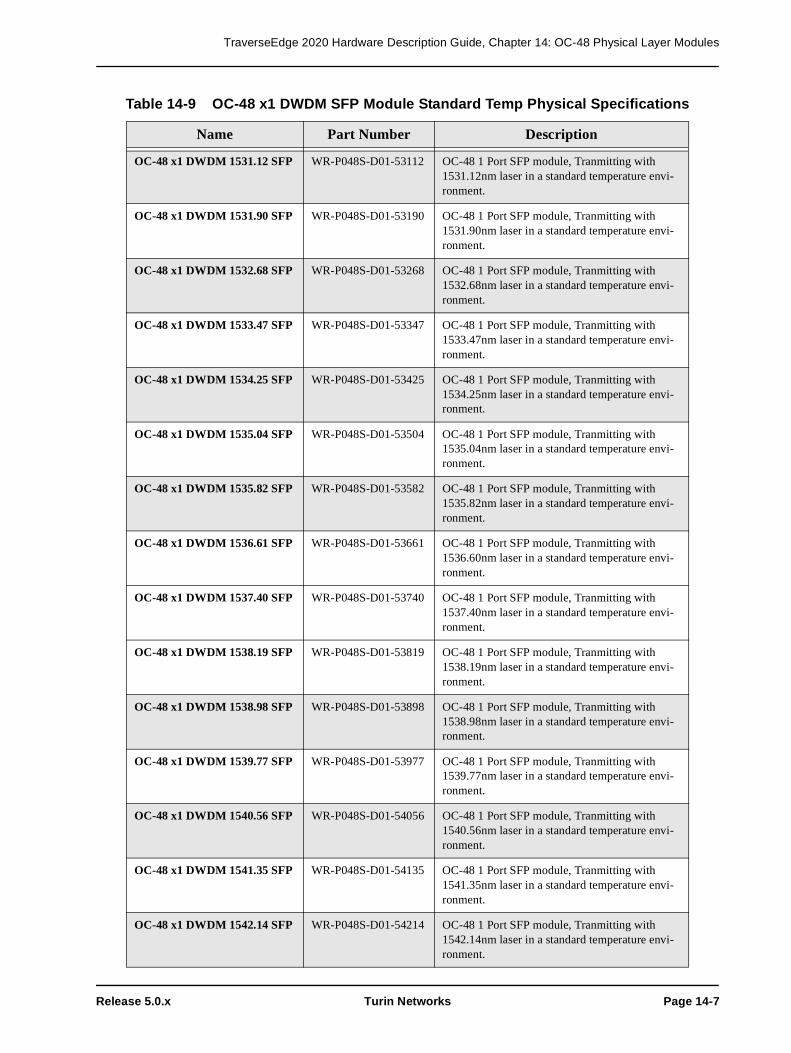
TraverseEdge 2020 Hardware Description Guide, Chapter 14: OC-48 Physical Layer Modules
Release 5.0.x Turin Networks Page 14-7
OC-48 x1 DWDM 1531.12 SFP WR-P048S-D01-53112 OC-48 1 Port SFP module, Tranmitting with 1531.12nm laser in a standard temperature envi-ronment.
OC-48 x1 DWDM 1531.90 SFP WR-P048S-D01-53190 OC-48 1 Port SFP module, Tranmitting with 1531.90nm laser in a standard temperature envi-ronment.
OC-48 x1 DWDM 1532.68 SFP WR-P048S-D01-53268 OC-48 1 Port SFP module, Tranmitting with 1532.68nm laser in a standard temperature envi-ronment.
OC-48 x1 DWDM 1533.47 SFP WR-P048S-D01-53347 OC-48 1 Port SFP module, Tranmitting with 1533.47nm laser in a standard temperature envi-ronment.
OC-48 x1 DWDM 1534.25 SFP WR-P048S-D01-53425 OC-48 1 Port SFP module, Tranmitting with 1534.25nm laser in a standard temperature envi-ronment.
OC-48 x1 DWDM 1535.04 SFP WR-P048S-D01-53504 OC-48 1 Port SFP module, Tranmitting with 1535.04nm laser in a standard temperature envi-ronment.
OC-48 x1 DWDM 1535.82 SFP WR-P048S-D01-53582 OC-48 1 Port SFP module, Tranmitting with 1535.82nm laser in a standard temperature envi-ronment.
OC-48 x1 DWDM 1536.61 SFP WR-P048S-D01-53661 OC-48 1 Port SFP module, Tranmitting with 1536.60nm laser in a standard temperature envi-ronment.
OC-48 x1 DWDM 1537.40 SFP WR-P048S-D01-53740 OC-48 1 Port SFP module, Tranmitting with 1537.40nm laser in a standard temperature envi-ronment.
OC-48 x1 DWDM 1538.19 SFP WR-P048S-D01-53819 OC-48 1 Port SFP module, Tranmitting with 1538.19nm laser in a standard temperature envi-ronment.
OC-48 x1 DWDM 1538.98 SFP WR-P048S-D01-53898 OC-48 1 Port SFP module, Tranmitting with 1538.98nm laser in a standard temperature envi-ronment.
OC-48 x1 DWDM 1539.77 SFP WR-P048S-D01-53977 OC-48 1 Port SFP module, Tranmitting with 1539.77nm laser in a standard temperature envi-ronment.
OC-48 x1 DWDM 1540.56 SFP WR-P048S-D01-54056 OC-48 1 Port SFP module, Tranmitting with 1540.56nm laser in a standard temperature envi-ronment.
OC-48 x1 DWDM 1541.35 SFP WR-P048S-D01-54135 OC-48 1 Port SFP module, Tranmitting with 1541.35nm laser in a standard temperature envi-ronment.
OC-48 x1 DWDM 1542.14 SFP WR-P048S-D01-54214 OC-48 1 Port SFP module, Tranmitting with 1542.14nm laser in a standard temperature envi-ronment.
Table 14-9 OC-48 x1 DWDM SFP Module Standard Temp Physical Specifications
Name Part Number Description

TraverseEdge 2020 Hardware Description Guide, Chapter 14: OC-48 Physical Layer Modules
Page 14-8 Turin Networks Release 5.0.x
OC-48 x1 DWDM 1542.94 SFP WR-P048S-D01-54294 OC-48 1 Port SFP module, Tranmitting with 1542.94nm laser in a standard temperature envi-ronment.
OC-48 x1 DWDM 1543.73 SFP WR-P048S-D01-54373 OC-48 1 Port SFP module, Tranmitting with 1543.73nm laser in a standard temperature envi-ronment.
OC-48 x1 DWDM 1544.53 SFP WR-P048S-D01-54453 OC-48 1 Port SFP module, Tranmitting with 1544.53nm laser in a standard temperature envi-ronment.
OC-48 x1 DWDM 1545.32 SFP WR-P048S-D01-54532 OC-48 1 Port SFP module, Tranmitting with 1545.32nm laser in a standard temperature envi-ronment.
OC-48 x1 DWDM 1546.12 SFP WR-P048S-D01-54612 OC-48 1 Port SFP module, Tranmitting with 1546.12nm laser in a standard temperature envi-ronment.
OC-48 x1 DWDM 1546.92 SFP WR-P048S-D01-54692 OC-48 1 Port SFP module, Tranmitting with 1546.92nm laser in a standard temperature envi-ronment.
OC-48 x1 DWDM 1547.72 SFP WR-P048S-D01-54772 OC-48 1 Port SFP module, Tranmitting with 1547.72nm laser in a standard temperature envi-ronment.
OC-48 x1 DWDM 1548.51 SFP WR-P048S-D01-54851 OC-48 1 Port SFP module, Tranmitting with 1548.51nm laser in a standard temperature envi-ronment.
OC-48 x1 DWDM 1549.32 SFP WR-P048S-D01-54932 OC-48 1 Port SFP module, Tranmitting with 1549.32nm laser in a standard temperature envi-ronment.
OC-48 x1 DWDM 1550.12 SFP WR-04801-T04-53504 OC-48 1 Port SFP module, Tranmitting with 1550.12nm laser in a standard temperature envi-ronment.
OC-48 x1 DWDM 1550.92 SFP WR-P048S-D01-55092 OC-48 1 Port SFP module, Tranmitting with 1550.92nm laser in a standard temperature envi-ronment.
OC-48 x1 DWDM 1551.72 SFP WR-P048S-D01-55172 OC-48 1 Port SFP module, Tranmitting with 1551.72nm laser in a standard temperature envi-ronment.
OC-48 x1 DWDM 1552.52 SFP WR-P048S-D01-55252 OC-48 1 Port SFP module, Tranmitting with 1552.52nm laser.
OC-48 x1 DWDM 1553.33 SFP WR-P048S-D01-55333 OC-48 1 Port SFP module, Tranmitting with 1553.33nm laser in a standard temperature envi-ronment.
OC-48 x1 DWDM 1554.13 SFP WR-P048S-D01-55413 OC-48 1 Port SFP module, Tranmitting with 1554.13nm laser in a standard temperature envi-ronment.
Table 14-9 OC-48 x1 DWDM SFP Module Standard Temp Physical Specifications
Name Part Number Description
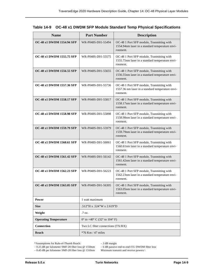
TraverseEdge 2020 Hardware Description Guide, Chapter 14: OC-48 Physical Layer Modules
Release 5.0.x Turin Networks Page 14-9
OC-48 x1 DWDM 1554.94 SFP WR-P048S-D01-55494 OC-48 1 Port SFP module, Tranmitting with 1554.94nm laser in a standard temperature envi-ronment.
OC-48 x1 DWDM 1555.75 SFP WR-P048S-D01-55575 OC-48 1 Port SFP module, Tranmitting with 1555.75nm laser in a standard temperature envi-ronment.
OC-48 x1 DWDM 1556.55 SFP WR-P048S-D01-55655 OC-48 1 Port SFP module, Tranmitting with 1556.55nm laser in a standard temperature envi-ronment.
OC-48 x1 DWDM 1557.36 SFP WR-P048S-D01-55736 OC-48 1 Port SFP module, Tranmitting with 1557.36 nm laser in a standard temperature envi-ronment.
OC-48 x1 DWDM 1558.17 SFP WR-P048S-D01-55817 OC-48 1 Port SFP module, Tranmitting with 1558.17nm laser in a standard temperature envi-ronment.
OC-48 x1 DWDM 1558.98 SFP WR-P048S-D01-55898 OC-48 1 Port SFP module, Tranmitting with 1558.98nm laser in a standard temperature envi-ronment.
OC-48 x1 DWDM 1559.79 SFP WR-P048S-D01-55979 OC-48 1 Port SFP module, Tranmitting with 1559.79nm laser in a standard temperature envi-ronment.
OC-48 x1 DWDM 1560.61 SFP WR-P048S-D01-56061 OC-48 1 Port SFP module, Tranmitting with 1560.61nm laser in a standard temperature envi-ronment.
OC-48 x1 DWDM 1561.42 SFP WR-P048S-D01-56142 OC-48 1 Port SFP module, Tranmitting with 1561.42nm laser in a standard temperature envi-ronment.
OC-48 x1 DWDM 1562.23 SFP WR-P048S-D01-56223 OC-48 1 Port SFP module, Tranmitting with 1562.23nm laser in a standard temperature envi-ronment.
OC-48 x1 DWDM 1563.05 SFP WR-P048S-D01-56305 OC-48 1 Port SFP module, Tranmitting with 1563.05nm laser in a standard temperature envi-ronment.
Power 1 watt maximum
Size .512”H x .524”W x 2.619”D
Weight .7 oz.
Operating Temperature 0° to +40° C (32° to 104° F)
Connection Two LC fiber connections (TX/RX)
Reach *76 Km / 47 miles
*Assumptions for Rule-of-Thumb Reach:– 0.25 dB per kilometer SMF-28 fiber loss @ 1550nm– 0.45 dB per kilometer SMF-28 fiber loss @ 1310nm
– 3 dB margin– 6 dB passive end-to-end ITU DWDM filter lossMinimum transmit and receive powers \
Table 14-9 OC-48 x1 DWDM SFP Module Standard Temp Physical Specifications
Name Part Number Description
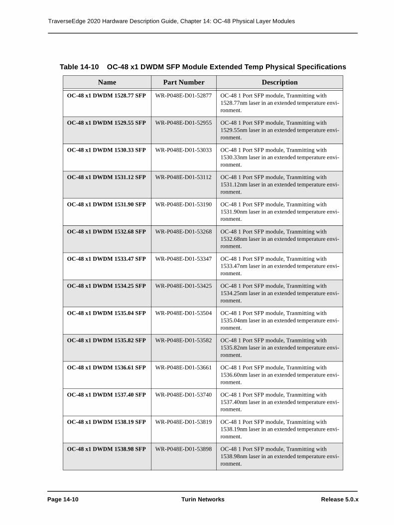
TraverseEdge 2020 Hardware Description Guide, Chapter 14: OC-48 Physical Layer Modules
Page 14-10 Turin Networks Release 5.0.x
Table 14-10 OC-48 x1 DWDM SFP Module Extended Temp Physical Specifications
Name Part Number Description
OC-48 x1 DWDM 1528.77 SFP WR-P048E-D01-52877 OC-48 1 Port SFP module, Tranmitting with 1528.77nm laser in an extended temperature envi-ronment.
OC-48 x1 DWDM 1529.55 SFP WR-P048E-D01-52955 OC-48 1 Port SFP module, Tranmitting with 1529.55nm laser in an extended temperature envi-ronment.
OC-48 x1 DWDM 1530.33 SFP WR-P048E-D01-53033 OC-48 1 Port SFP module, Tranmitting with 1530.33nm laser in an extended temperature envi-ronment.
OC-48 x1 DWDM 1531.12 SFP WR-P048E-D01-53112 OC-48 1 Port SFP module, Tranmitting with 1531.12nm laser in an extended temperature envi-ronment.
OC-48 x1 DWDM 1531.90 SFP WR-P048E-D01-53190 OC-48 1 Port SFP module, Tranmitting with 1531.90nm laser in an extended temperature envi-ronment.
OC-48 x1 DWDM 1532.68 SFP WR-P048E-D01-53268 OC-48 1 Port SFP module, Tranmitting with 1532.68nm laser in an extended temperature envi-ronment.
OC-48 x1 DWDM 1533.47 SFP WR-P048E-D01-53347 OC-48 1 Port SFP module, Tranmitting with 1533.47nm laser in an extended temperature envi-ronment.
OC-48 x1 DWDM 1534.25 SFP WR-P048E-D01-53425 OC-48 1 Port SFP module, Tranmitting with 1534.25nm laser in an extended temperature envi-ronment.
OC-48 x1 DWDM 1535.04 SFP WR-P048E-D01-53504 OC-48 1 Port SFP module, Tranmitting with 1535.04nm laser in an extended temperature envi-ronment.
OC-48 x1 DWDM 1535.82 SFP WR-P048E-D01-53582 OC-48 1 Port SFP module, Tranmitting with 1535.82nm laser in an extended temperature envi-ronment.
OC-48 x1 DWDM 1536.61 SFP WR-P048E-D01-53661 OC-48 1 Port SFP module, Tranmitting with 1536.60nm laser in an extended temperature envi-ronment.
OC-48 x1 DWDM 1537.40 SFP WR-P048E-D01-53740 OC-48 1 Port SFP module, Tranmitting with 1537.40nm laser in an extended temperature envi-ronment.
OC-48 x1 DWDM 1538.19 SFP WR-P048E-D01-53819 OC-48 1 Port SFP module, Tranmitting with 1538.19nm laser in an extended temperature envi-ronment.
OC-48 x1 DWDM 1538.98 SFP WR-P048E-D01-53898 OC-48 1 Port SFP module, Tranmitting with 1538.98nm laser in an extended temperature envi-ronment.

TraverseEdge 2020 Hardware Description Guide, Chapter 14: OC-48 Physical Layer Modules
Release 5.0.x Turin Networks Page 14-11
OC-48 x1 DWDM 1539.77 SFP WR-P048E-D01-53977 OC-48 1 Port SFP module, Tranmitting with 1539.77nm laser in an extended temperature envi-ronment.
OC-48 x1 DWDM 1540.56 SFP WR-P048E-D01-54056 OC-48 1 Port SFP module, Tranmitting with 1540.56nm laser in an extended temperature envi-ronment.
OC-48 x1 DWDM 1541.35 SFP WR-P048E-D01-54135 OC-48 1 Port SFP module, Tranmitting with 1541.35nm laser in an extended temperature envi-ronment.
OC-48 x1 DWDM 1542.14 SFP WR-P048E-D01-54214 OC-48 1 Port SFP module, Tranmitting with 1542.14nm laser in an extended temperature envi-ronment.
OC-48 x1 DWDM 1542.94 SFP WR-P048E-D01-54294 OC-48 1 Port SFP module, Tranmitting with 1542.94nm laser in an extended temperature envi-ronment.
OC-48 x1 DWDM 1543.73 SFP WR-P048E-D01-54373 OC-48 1 Port SFP module, Tranmitting with 1543.73nm laser in an extended temperature envi-ronment.
OC-48 x1 DWDM 1544.53 SFP WR-P048E-D01-54453 OC-48 1 Port SFP module, Tranmitting with 1544.53nm laser in an extended temperature envi-ronment.
OC-48 x1 DWDM 1545.32 SFP WR-P048E-D01-54532 OC-48 1 Port SFP module, Tranmitting with 1545.32nm laser in an extended temperature envi-ronment.
OC-48 x1 DWDM 1546.12 SFP WR-P048E-D01-54612 OC-48 1 Port SFP module, Tranmitting with 1546.12nm laser in an extended temperature envi-ronment.
OC-48 x1 DWDM 1546.92 SFP WR-P048E-D01-54692 OC-48 1 Port SFP module, Tranmitting with 1546.92nm laser in an extended temperature envi-ronment.
OC-48 x1 DWDM 1547.72 SFP WR-P048E-D01-54772 OC-48 1 Port SFP module, Tranmitting with 1547.72nm laser in an extended temperature envi-ronment.
OC-48 x1 DWDM 1548.51 SFP WR-P048E-D01-54851 OC-48 1 Port SFP module, Tranmitting with 1548.51nm laser in an extended temperature envi-ronment.
OC-48 x1 DWDM 1549.32 SFP WR-P048E-D01-54932 OC-48 1 Port SFP module, Tranmitting with 1549.32nm laser in an extended temperature envi-ronment.
OC-48 x1 DWDM 1550.12 SFP WR-P048E-D04-55012 OC-48 1 Port SFP module, Tranmitting with 1550.12nm laser in an extended temperature envi-ronment.
OC-48 x1 DWDM 1550.92 SFP WR-P048E-D01-55092 OC-48 1 Port SFP module, Tranmitting with 1550.92nm laser in an extended temperature envi-ronment.
Table 14-10 OC-48 x1 DWDM SFP Module Extended Temp Physical Specifications
Name Part Number Description
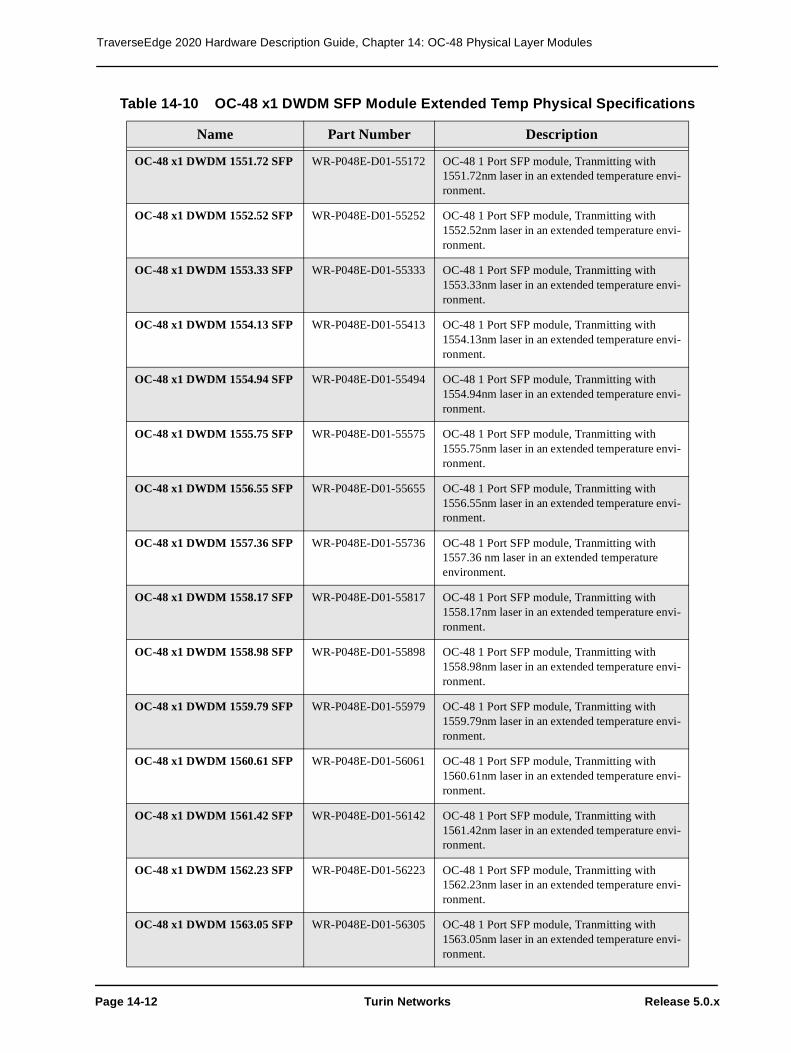
TraverseEdge 2020 Hardware Description Guide, Chapter 14: OC-48 Physical Layer Modules
Page 14-12 Turin Networks Release 5.0.x
OC-48 x1 DWDM 1551.72 SFP WR-P048E-D01-55172 OC-48 1 Port SFP module, Tranmitting with 1551.72nm laser in an extended temperature envi-ronment.
OC-48 x1 DWDM 1552.52 SFP WR-P048E-D01-55252 OC-48 1 Port SFP module, Tranmitting with 1552.52nm laser in an extended temperature envi-ronment.
OC-48 x1 DWDM 1553.33 SFP WR-P048E-D01-55333 OC-48 1 Port SFP module, Tranmitting with 1553.33nm laser in an extended temperature envi-ronment.
OC-48 x1 DWDM 1554.13 SFP WR-P048E-D01-55413 OC-48 1 Port SFP module, Tranmitting with 1554.13nm laser in an extended temperature envi-ronment.
OC-48 x1 DWDM 1554.94 SFP WR-P048E-D01-55494 OC-48 1 Port SFP module, Tranmitting with 1554.94nm laser in an extended temperature envi-ronment.
OC-48 x1 DWDM 1555.75 SFP WR-P048E-D01-55575 OC-48 1 Port SFP module, Tranmitting with 1555.75nm laser in an extended temperature envi-ronment.
OC-48 x1 DWDM 1556.55 SFP WR-P048E-D01-55655 OC-48 1 Port SFP module, Tranmitting with 1556.55nm laser in an extended temperature envi-ronment.
OC-48 x1 DWDM 1557.36 SFP WR-P048E-D01-55736 OC-48 1 Port SFP module, Tranmitting with 1557.36 nm laser in an extended temperature environment.
OC-48 x1 DWDM 1558.17 SFP WR-P048E-D01-55817 OC-48 1 Port SFP module, Tranmitting with 1558.17nm laser in an extended temperature envi-ronment.
OC-48 x1 DWDM 1558.98 SFP WR-P048E-D01-55898 OC-48 1 Port SFP module, Tranmitting with 1558.98nm laser in an extended temperature envi-ronment.
OC-48 x1 DWDM 1559.79 SFP WR-P048E-D01-55979 OC-48 1 Port SFP module, Tranmitting with 1559.79nm laser in an extended temperature envi-ronment.
OC-48 x1 DWDM 1560.61 SFP WR-P048E-D01-56061 OC-48 1 Port SFP module, Tranmitting with 1560.61nm laser in an extended temperature envi-ronment.
OC-48 x1 DWDM 1561.42 SFP WR-P048E-D01-56142 OC-48 1 Port SFP module, Tranmitting with 1561.42nm laser in an extended temperature envi-ronment.
OC-48 x1 DWDM 1562.23 SFP WR-P048E-D01-56223 OC-48 1 Port SFP module, Tranmitting with 1562.23nm laser in an extended temperature envi-ronment.
OC-48 x1 DWDM 1563.05 SFP WR-P048E-D01-56305 OC-48 1 Port SFP module, Tranmitting with 1563.05nm laser in an extended temperature envi-ronment.
Table 14-10 OC-48 x1 DWDM SFP Module Extended Temp Physical Specifications
Name Part Number Description

TraverseEdge 2020 Hardware Description Guide, Chapter 14: OC-48 Physical Layer Modules
Release 5.0.x Turin Networks Page 14-13
14.2.3 Dual Port OC-48 PLMs
Table 14-11 OC-48 x2 PLM, IR-1 Physical Specifications
Table 14-12 OC-48 x2 PLM, LR-1 Physical Specifications
14.2.4 Four Port OC-48 PLMs
Power 1 watt maximum
Size .512”H x .524”W x 2.619”D
Weight .7 oz.
Operating Temperature -40° to +65° C (40° to 149° F)
Connection Two LC fiber connections (TX/RX)
Reach *76 Km / 47 miles
*Assumptions for Rule-of-Thumb Reach:– 0.25 dB per kilometer SMF-28 fiber loss @ 1550nm– 0.45 dB per kilometer SMF-28 fiber loss @ 1310nm
– 3 dB margin– 6 dB passive end-to-end ITU DWDM filter lossMinimum transmit and receive powers \
OC-48 x2 PLM, IR-1 Physical Specifications
Part Number WR-04802-I01-31000
Power 22 watts maximum
Size .75”H x 3.5”W x 6”D
Weight 9.6 oz.
Operating Temperature -5° to +55° C (23° to 131° F)
OC-48 x2 PLM, LR-1 Physical Specifications
Part Number WR-04802-L01-31000
Power 22 watts maximum
Size .75”H x 3.5”W x 6”D
Weight 9.6 oz.
Operating Temperature -5° to +55° C (23° to 131° F)
Table 14-10 OC-48 x1 DWDM SFP Module Extended Temp Physical Specifications
Name Part Number Description

TraverseEdge 2020 Hardware Description Guide, Chapter 14: OC-48 Physical Layer Modules
Page 14-14 Turin Networks Release 5.0.x
Table 14-13 OC-48 x4 IR 1310 PLM Physical Specifications
Table 14-14 OC-48 x4 LR-1 1310 PLM Physical Specifications
Table 14-15 OC-48 x4 PLM, LR-2 Physical Specifications
14.3 Optical Parameters
14.3.1 OC-48 Optical Parameters
The OC-48 PLM Intermediate Reach (IR) version and Long Reach (LR and VR) versions all have Single Mode Fiber connectors and pigtails as well as Single Longitudinal Mode (SLM) sources. Table 14-16 , Table 14-17 , and Table 14-18 give the Optical Parameters for each type of PLM.
NOTE: For further definitions of the parameters listed, refer to the Optical Link Design chapter in the TE-2020 Applications and Engineering Manual.
OC-48 x4 PLM, IR Physical Specifications
Part Number WR-04804-I01-31000
Power 37 watts maximum
Size 1.0”H x 6.9”W x 10.9”D
Weight 32 oz.
Operating Temperature -5° to 55° C (23° to 131° F)
OC-48 x4 PLM, LR-1 Physical Specifications
Part Number WR-04804-L01-31000
Power 37 watts maximum
Size 1.0”H x 6.9”W x 10.9”D
Weight 32 oz.
Operating Temperature -5° to +55° C (23° to 131° F)
OC-48 x4 PLM, LR-2 Physical Specifications
Part Number WR-04804-L01-55000
Power 37 watts maximum
Size 1.0”H x 6.9”W x 10.9”D
Weight 32 oz.
Operating Temperature -5° to +55° C (23° to 131° F)
TraverseEdge 2020 Hardware Description Guide, Chapter 14: OC-48 Physical Layer Modules
Release 5.0.x Turin Networks Page 14-15
Table 14-16 OC-48 IR Optical Parameters
Table 14-17 OC-48 Optical Parameters
Parameter IR-1 Unit
Transmitter SLM
λTmin-λTmax 1266-1360 nm
∆λrms(max) NA nm
∆λ20(max) 1 nm
SSRmin 30 dB
PTmax 0 dBm
PTmin -5 dBm
re(min) 8.2 db
Optical Path
System ORLmin 24 dB
DSR(max) NA ps/nm
Attenuation 0-15 dB
Max. Reflectance between S and R -27 dB
Receiver
PRmax 0 dBm
PRmin -18 dBm
PO 1 dB
Receiver Reflectance (max) -27 dB
Parameter LR-1 LR-2 VR-1 Unit
Transmitter SLM SLM SLM
λTmin-λTmax 1280-1335 1500-1580 1280-1335 nm
∆λrms(max) NA NA NA nm
∆λ20(max) 1 <1 1 nm
SSRmin 30 30 30 dB
PTmax +3 +3 +9 dBm
PTmin -2 -2 +3 dBm
re(min) 8.2 8.2 8.2 db
Optical Path

TraverseEdge 2020 Hardware Description Guide, Chapter 14: OC-48 Physical Layer Modules
Page 14-16 Turin Networks Release 5.0.x
Table 14-18 OC-48 DWDM SFP Optical Parameters
System ORLmin 24 24 24 dB
DSR(max) NA 1600 NA ps/nm
Attenuation 12-27 12-27 18-32 dB
Max. Reflectance between S and R -27 -27 -27 dB
Receiver
PRmax -9 -9 -9 dBm
PRmin -28 -28 -28 dBm
PO 1 2 1 dB
Receiver Reflectance (max) -27 -27 -27 dB
Parameter LR-2 Unit
Transmitter DFB
λTmin-λTmax 1528.77-1563.45 (1 wavelength per unit)
nm
PTmax +1.5 dBm
PTmin +0 dBm
re(min) 8.2 dB
Optical Path
System ORLmin 24 dB
DSR(max) 1600 ps/nm
Attenuation (min-max) 11 to 22 dB
Max. Reflectance between S and R -24 dB
Receiver
PRmax -6 (Rsens High)+4 (Damage)
dBm
PRmin -28 dBm
PO 2 dB
Receiver Reflectance (max) -27 dB
Parameter LR-1 LR-2 VR-1 Unit

TraverseEdge 2020 Hardware Description Guide, Chapter 14: OC-48 Physical Layer Modules
Release 5.0.x Turin Networks Page 14-17
14.4 Connectorization
14.4.1 Single Port Connector
The single-port PLM front panel has individual LC connectors for Transmit and Receive that provide fiber access to the OC-48 PLM. Figure 14-5 shows the single LC connector on the left and teh dual LC connec-tor on the right. Figure 14-6 and Figure 14-7 show the OC-48 PLM connectors, and Table 14-20 docu-ments the port functionality.
Figure 14-5 Single and Dual LC Connectors
Table 14-19 OC-48 DWDM Wavelengths Available
SFP Available Wavelengths (nm)
1528.77 1529.55 1530.33 1531.12
1531.90 1532.68 1533.47 1534.25
1535.04 1535.82 1536.61 1537.40
1538.19 1538.98 1539.77 1540.56
1541.35 1542.14 1542.94 1543.73
1544.53 1545.32 1546.12 1546.92
1547.72 1548.51 1549.32 1550.12
1550.92 1551.72 1552.52 1553.33
1554.13 1554.94 1555.75 1556.55
1557.36 1558.17 1558.98 1559.79
1560.61 1561.42 1562.23 1563.05
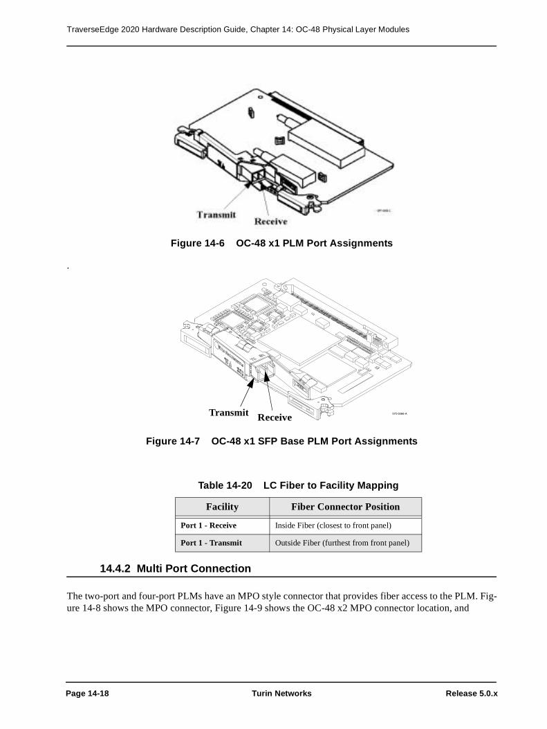
TraverseEdge 2020 Hardware Description Guide, Chapter 14: OC-48 Physical Layer Modules
Page 14-18 Turin Networks Release 5.0.x
Figure 14-6 OC-48 x1 PLM Port Assignments
.
Figure 14-7 OC-48 x1 SFP Base PLM Port Assignments
14.4.2 Multi Port Connection
The two-port and four-port PLMs have an MPO style connector that provides fiber access to the PLM. Fig-ure 14-8 shows the MPO connector, Figure 14-9 shows the OC-48 x2 MPO connector location, and
Table 14-20 LC Fiber to Facility Mapping
Facility Fiber Connector Position
Port 1 - Receive Inside Fiber (closest to front panel)
Port 1 - Transmit Outside Fiber (furthest from front panel)
TransmitReceive
SYS-0366-ATransmit Receive

TraverseEdge 2020 Hardware Description Guide, Chapter 14: OC-48 Physical Layer Modules
Release 5.0.x Turin Networks Page 14-19
Table 14-21 documents the MPO facility to fiber mapping.
Figure 14-8 MPO Connector Diagram
.
Figure 14-9 OC-48 x2 PLM MPO Port
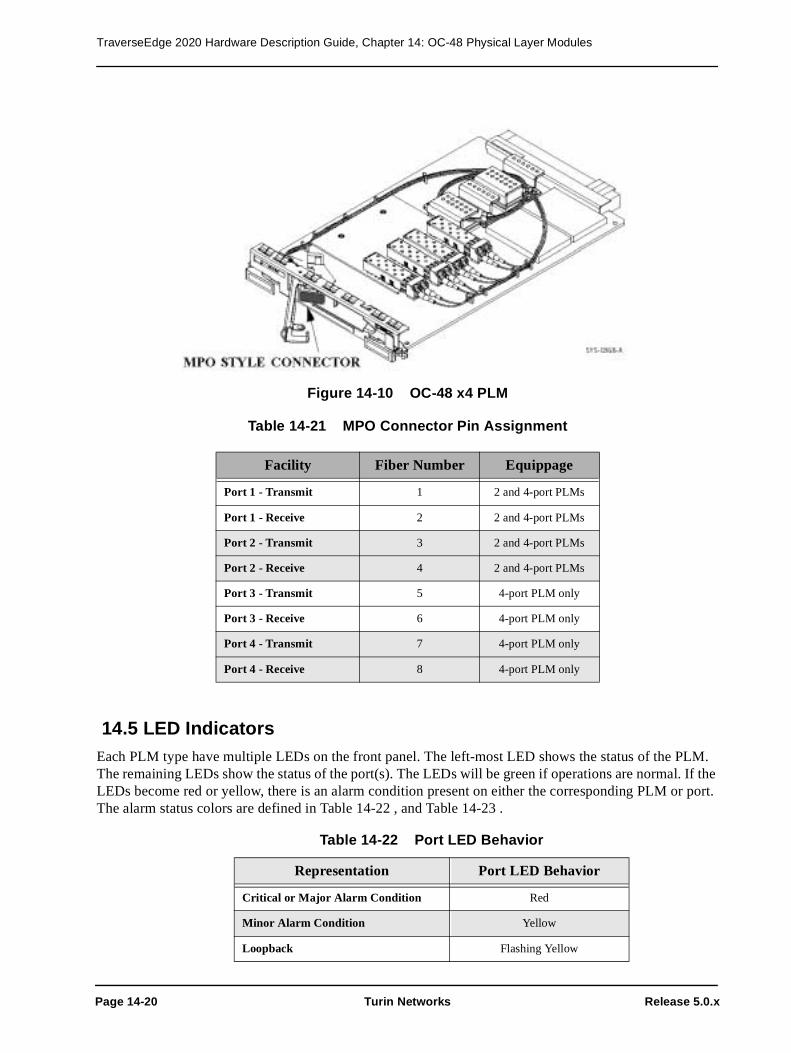
TraverseEdge 2020 Hardware Description Guide, Chapter 14: OC-48 Physical Layer Modules
Page 14-20 Turin Networks Release 5.0.x
Figure 14-10 OC-48 x4 PLM
Table 14-21 MPO Connector Pin Assignment
14.5 LED IndicatorsEach PLM type have multiple LEDs on the front panel. The left-most LED shows the status of the PLM. The remaining LEDs show the status of the port(s). The LEDs will be green if operations are normal. If the LEDs become red or yellow, there is an alarm condition present on either the corresponding PLM or port. The alarm status colors are defined in Table 14-22 , and Table 14-23 .
Facility Fiber Number Equippage
Port 1 - Transmit 1 2 and 4-port PLMs
Port 1 - Receive 2 2 and 4-port PLMs
Port 2 - Transmit 3 2 and 4-port PLMs
Port 2 - Receive 4 2 and 4-port PLMs
Port 3 - Transmit 5 4-port PLM only
Port 3 - Receive 6 4-port PLM only
Port 4 - Transmit 7 4-port PLM only
Port 4 - Receive 8 4-port PLM only
Table 14-22 Port LED Behavior
Representation Port LED Behavior
Critical or Major Alarm Condition Red
Minor Alarm Condition Yellow
Loopback Flashing Yellow

TraverseEdge 2020 Hardware Description Guide, Chapter 14: OC-48 Physical Layer Modules
Release 5.0.x Turin Networks Page 14-21
14.6 CCT ConnectorsThe CCT connector on the leading edge (inserted first in the PLM slot) provides power as well as data and management connectivity between the CCTs and the PLMs.
Normal, No Alarm Conditions Green
No Power, Out-of-Service Off
Table 14-23 PLM Status LED Behavior
Representation Status LED Behavior
Board Failure Red
Normal Green
No Power, Out-of-Service Off
Table 14-22 Port LED Behavior

TraverseEdge 2020 Hardware Description Guide, Chapter 14: OC-48 Physical Layer Modules
Page 14-22 Turin Networks Release 5.0.x

Release 5.0.x Turin Networks Page 15-1
Chapter 15 OC-12 Physical Layer Modules
This chapter covers both the two-port and four-port versions of the OC-12 PLM. For information on either one, refer to the following sections:
15.1 OC-12 x2 PLM15.2 OC-12 x4 PLM
15.1 OC-12 x2 PLMThe OC-12 x2 Physical Layer Module (PLM) is a two port plug-in module that can be used in the TE-2020 Main Shelf or the OTS2. The OC-12 x2 PLM must be installed in a CCT that has already been installed in the shelf. The OC-12 x2 PLM provides the following functionality and connectivity:
• Two OC-12, 1310 nm optical user interfaces
• IR (Intermediate Reach) and LR-1 and LR-2 (Long Reach) versions• A single MPO connector for both interfaces
• Ejector handles for card installation and removal• CCT connector
• Three LEDs to indicate Card and Port Status• SONET/SDH framing functions
• O/E and E/O conversion• Clock recovery and clock generation
Figure 15-1 OC-12 x2 PLM
15.1.1 Configurations
The OC-12 x2 PLM can be configured to support the configurations below. Consult the TE-2020 Applica-tions and Engineering Manual (WR-D2020-APP-040000) for configuration details.
TraverseEdge 2020 Hardware Description Guide, Chapter 15: OC-12 Physical Layer Modules
Page 15-2 Turin Networks Release 5.0.x
• Unprotected• 1+1 Protected
• UPSR
15.1.2 Physical Specifications
The OC-12 x2 PLM is available in either an Intermediate Reach (IR) version or a Long Reach (LR) ver-sion, both of which have Single Mode Fiber connectors and pigtails. Table 15-1 and Table 15-2 provide physical specifications these versions.
Table 15-1 OC-12 x2 PLM, IR Physical Specifications
OC-12 x2 PLM, IR Physical Specifications
Part No. WR-01202-I01-31000
Power 9.1 watts maximum
Size .75”H x 3.5”W x 6”D
Weight 9.6 oz.
Operating Temperature -5° to 55° C (23° to 131° F)
Table 15-2 OC-12 x2 PLM, LR-1 Physical Specifications
OC-12 x2 PLM, LR-1 Physical Specifications
Part No. WR-01202-L01-31000
Power 11 watts maximum
Size .75”H x 3.5”W x 6”D
Weight 9.6 oz.
Operating Temperature -5° to 55° C (23° to 131° F)
Table 15-3 OC-12 x2 PLM, LR-2 Physical Specifications
OC-12 x2 PLM, LR-2 Physical Specifications
Part No. WR-01202-L01-55000
Power 11 watts maximum
Size .75”H x 3.5”W x 6”D
Weight 9.6 oz.
Operating Temperature -5° to 55° C (23° to 131° F)

TraverseEdge 2020 Hardware Description Guide, Chapter 15: OC-12 Physical Layer Modules
Release 5.0.x Turin Networks Page 15-3
15.1.3 Optical Parameters
The OC-12 x2 PLM Intermediate Reach (IR) version and Long Reach (LR) version both have Single Mode Fiber connectors. Table 15-4 and Table 15-5 give the Optical Parameters for each type of PLM.
NOTE: For further definitions of the parameters listed, refer to the Optical Link Design chapter in the TE-2020 Applications and Engineering Manual.
Table 15-4 OC-12 x2 IR Optical Parameters
Parameter IR Unit
Transmitter - SLM
λTmin-λTmax 1274-1356or
1293-1334
nm
∆λrms(max) 2.5or 4.0
nm
∆λ20(max) 1 nm
SSRmin N/A dB
PTmax -8 dBm
PTmin -15 dBm
re(min) 8.2 db
Optical Path
System ORLmin 24 dB
DSR(max) NA ps/nm
Attenuation 0-13 dB
Max. Reflectance between S and R -27 dB
Receiver
PRmax -8 dBm
PRmin -28 dBm
PO 1 dB
Receiver Reflectance (max) -27 dB

TraverseEdge 2020 Hardware Description Guide, Chapter 15: OC-12 Physical Layer Modules
Page 15-4 Turin Networks Release 5.0.x
15.1.4 Functional Description
The OC-12 x2 PLM provides the following functions:
• Two OC-12, 1310 nm or 1550 nm optical user interfaces• CCT Connector
• Three LEDs to indicate Card and Port Status• SONET/SDH framing functions
• O/E and E/O conversion• Clock recovery and clock generation
Table 15-5 OC-12 x2 LR Optical Parameters
Parameter LR-1 LR-2 Unit
Transmitter - SLM
λTmin-λTmax 1280-1335 1500-1580 nm
∆λrms(max) NA NA nm
∆λ20(max) 1.0 <1 nm
SSRmin 30 30 dB
PTmax +2 +3 dBm
PTmin -3 -2 dBm
re(min) 10 8.2 db
Optical Path
System ORLmin 20 24 dB
DSR(max) NA 1600 ps/nm
Attenuation 9-25 12-27 dB
Max. Reflectance between S and R -25 -27 dB
Receiver
PRmax -8 -9 dBm
PRmin -28 -28 dBm
PO 1 2 dB
Receiver Reflectance (max) -14 -27 dB

TraverseEdge 2020 Hardware Description Guide, Chapter 15: OC-12 Physical Layer Modules
Release 5.0.x Turin Networks Page 15-5
15.1.5 Connectorization
The front panel has an MPO connector that provides fiber access to the OC-12 x2 PLM. Figure 15-2 shows the features of an MPO connector and Table 15-6 documents the MPO facility to fiber mapping.
Figure 15-2 MPO Connector Diagram
15.1.6 LED Indicators
An OC-12 x2 PLM has three LEDs on the front panel. The first LED shows the status of the PLM card. The remaining LEDs show the status of each individual port. The LEDs will be green if operations are nor-
Table 15-6 MPO Fiber to Facility Mapping
Facility Fiber Number
Port 1 - Transmit 1
Port 1 - Receive 2
Port 2 - Transmit 3
Port 2 - Receive 4

TraverseEdge 2020 Hardware Description Guide, Chapter 15: OC-12 Physical Layer Modules
Page 15-6 Turin Networks Release 5.0.x
mal. If the LEDs become red or yellow, there is an alarm condition present on either the corresponding PLM or port. The alarm status colors are defined in Table 15-7 and Table 15-8 .
15.1.7 CCT Connectors
The CCT connector on the leading edge (inserted first in the PLM slot) provides power as well as data and management connectivity between the CCTs and the PLMs.
15.2 OC-12 x4 PLMThe OC-12 x4 Physical Layer Module (PLM) is a four port plug-in module that can be used in the TE-2020 Main Shelf or the OTS2. The OC-12 x4 PLM must be installed in a CCT that has already been installed in the shelf. The OC-12 x4 PLM provides the following functionality and connectivity:
• Four OC-12, 1310nm optical user interfaces• IR (Intermediate Reach), LR-1 and LR-2 (Long Reach) versions
• A single MPO connector for all four interfaces• Ejector handles for card installation and removal
• CCT connector• Five LEDs to indicate Card and Port Status
• SONET/SDH framing functions• O/E and E/O conversion
• Clock recovery and clock generation
Table 15-7 Port LED Behavior
Representation Port LED Behavior
Critical or Major Alarm Condition Red
Minor Alarm Condition Yellow
Loopback Flashing Yellow
Normal, No Alarm Conditions Green
No Power, Out-of-Service Off
Table 15-8 PLM Status LED Behavior
Representation Status LED Behavior
Board Failure Red
Normal Green
No Power, Out-of-Service Off
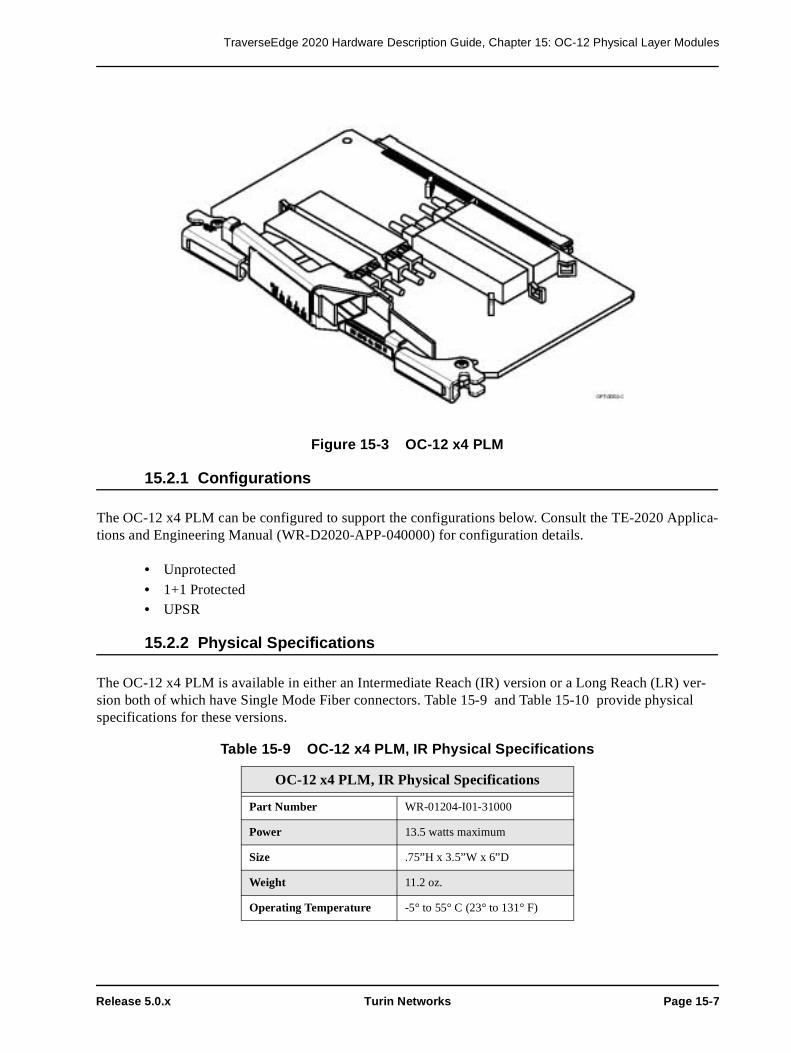
TraverseEdge 2020 Hardware Description Guide, Chapter 15: OC-12 Physical Layer Modules
Release 5.0.x Turin Networks Page 15-7
Figure 15-3 OC-12 x4 PLM
15.2.1 Configurations
The OC-12 x4 PLM can be configured to support the configurations below. Consult the TE-2020 Applica-tions and Engineering Manual (WR-D2020-APP-040000) for configuration details.
• Unprotected
• 1+1 Protected• UPSR
15.2.2 Physical Specifications
The OC-12 x4 PLM is available in either an Intermediate Reach (IR) version or a Long Reach (LR) ver-sion both of which have Single Mode Fiber connectors. Table 15-9 and Table 15-10 provide physical specifications for these versions.
Table 15-9 OC-12 x4 PLM, IR Physical Specifications
OC-12 x4 PLM, IR Physical Specifications
Part Number WR-01204-I01-31000
Power 13.5 watts maximum
Size .75”H x 3.5”W x 6”D
Weight 11.2 oz.
Operating Temperature -5° to 55° C (23° to 131° F)

TraverseEdge 2020 Hardware Description Guide, Chapter 15: OC-12 Physical Layer Modules
Page 15-8 Turin Networks Release 5.0.x
15.2.3 Optical Parameters
The OC-12 x4 PLM Intermediate Reach (IR) version and Long Reach (LR) version both have Single Mode Fiber connectors and Single Longitudinal Mode (SLM) sources. Table 15-12 and Table 15-14 give the Optical Parameters for each type of PLM.
NOTE: For further definitions of the parameters listed, refer to the Optical Link Design chapter in the TE-2020 Applications and Engineering Manual.
Table 15-10 OC-12 x4 PLM, LR-1 Physical Specifications
OC-12 x4 PLM, LR-1 Physical Specifications
Part Number WR-01204-L01-31000
Power 16 watts maximum
Size .75”H x 3.5”W x 6”D
Weight 11.2 oz.
Operating Temperature -5° to 55° C (23° to 131° F)
Table 15-11 OC-12 x4 PLM, LR-2 Physical Specifications
OC-12 x4 PLM, LR-2 Physical Specifications
Part Number WR-01204-L01-55000
Power 16 watts maximum
Size .75”H x 3.5”W x 6”D
Weight 11.2 oz.
Operating Temperature -5° to 55° C (23° to 131° F)
Table 15-12 OC-12 x4 IR Optical Parameters
Parameter IR Unit
Transmitter - SLM
λTmin-λTmax 1274-1356or
1293-1334
nm
∆λrms(max) 2.5or 4.0
nm
∆λ20(max) 1 nm
SSRmin N/A dB
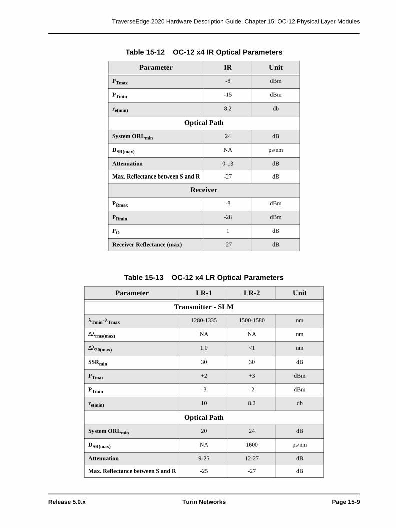
TraverseEdge 2020 Hardware Description Guide, Chapter 15: OC-12 Physical Layer Modules
Release 5.0.x Turin Networks Page 15-9
PTmax -8 dBm
PTmin -15 dBm
re(min) 8.2 db
Optical Path
System ORLmin 24 dB
DSR(max) NA ps/nm
Attenuation 0-13 dB
Max. Reflectance between S and R -27 dB
Receiver
PRmax -8 dBm
PRmin -28 dBm
PO 1 dB
Receiver Reflectance (max) -27 dB
Table 15-13 OC-12 x4 LR Optical Parameters
Parameter LR-1 LR-2 Unit
Transmitter - SLM
λTmin-λTmax 1280-1335 1500-1580 nm
∆λrms(max) NA NA nm
∆λ20(max) 1.0 <1 nm
SSRmin 30 30 dB
PTmax +2 +3 dBm
PTmin -3 -2 dBm
re(min) 10 8.2 db
Optical Path
System ORLmin 20 24 dB
DSR(max) NA 1600 ps/nm
Attenuation 9-25 12-27 dB
Max. Reflectance between S and R -25 -27 dB
Table 15-12 OC-12 x4 IR Optical Parameters
Parameter IR Unit
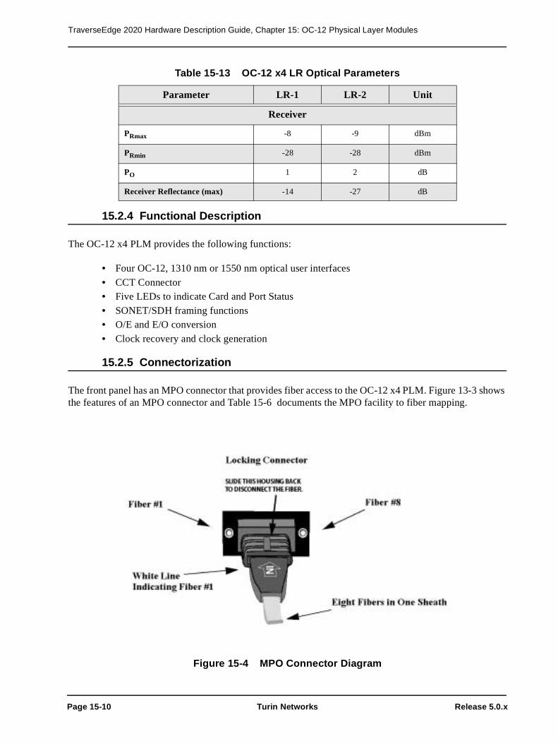
TraverseEdge 2020 Hardware Description Guide, Chapter 15: OC-12 Physical Layer Modules
Page 15-10 Turin Networks Release 5.0.x
15.2.4 Functional Description
The OC-12 x4 PLM provides the following functions:
• Four OC-12, 1310 nm or 1550 nm optical user interfaces
• CCT Connector• Five LEDs to indicate Card and Port Status
• SONET/SDH framing functions• O/E and E/O conversion
• Clock recovery and clock generation
15.2.5 Connectorization
The front panel has an MPO connector that provides fiber access to the OC-12 x4 PLM. Figure 13-3 shows the features of an MPO connector and Table 15-6 documents the MPO facility to fiber mapping.
Figure 15-4 MPO Connector Diagram
Receiver
PRmax -8 -9 dBm
PRmin -28 -28 dBm
PO 1 2 dB
Receiver Reflectance (max) -14 -27 dB
Table 15-13 OC-12 x4 LR Optical Parameters
Parameter LR-1 LR-2 Unit
TraverseEdge 2020 Hardware Description Guide, Chapter 15: OC-12 Physical Layer Modules
Release 5.0.x Turin Networks Page 15-11
15.2.6 LED Indicators
An OC-12 x4 PLM has five LEDs on the front panel. The first LED shows the status of the PLM card. The remaining LEDs show the status of each individual port. The LEDs will be green if operations are normal. If the LEDs become red or yellow, there is an alarm condition present on either the corresponding PLM or port. The alarm status colors are defined in Table 15-15 and Table 15-16 below.
15.2.7 CCT Connectors
The CCT connector on the leading edge (inserted first in the PLM slot) provides power as well as data and management connectivity between the CCTs and the PLMs.
Table 15-14 MPO Fiber to Facility Mapping
Facility Fiber Number
Port 1 - Transmit 1
Port 1 - Receive 2
Port 2 - Transmit 3
Port 2 - Receive 4
Port 3 - Transmit 5
Port 3 - Receive 6
Port 4 - Transmit 7
Port 4 - Receive 8
Table 15-15 Port LED Behavior
Representation Port LED Behavior
Critical or Major Alarm Condition Red
Minor Alarm Condition Yellow
Loopback Flashing Yellow
Normal, No Alarm Conditions Green
No Power, Out-of-Service Off
Table 15-16 PLM Status LED Behavior
Representation Status LED Behavior
Board Failure Red
Normal Green
No Power, Out-of-Service Off

TraverseEdge 2020 Hardware Description Guide, Chapter 15: OC-12 Physical Layer Modules
Page 15-12 Turin Networks Release 5.0.x

Release 5.0.x Turin Networks Page 16-1
Chapter 16 OC-3 Physical Layer Modules
The OC-3 x4 Physical Layer Module (PLM) is a four port plug-in module that can be used in the TE-2020 Main Shelf or the OTS2. The OC-3 x4 PLM must be installed in a CCT that has already been installed in the shelf and provides the following functionality and connectivity:
• Four OC-3, 1310 nm or 1550 nm optical user interfaces• IR (Intermediate Reach) and LR-1 (Long Reach) versions
• A single MPO connector for all four interfaces• Ejector handles for card installation and removal
• CCT connector• Five LEDs to indicate Card and Port Status
• SONET/SDH framing functions• O/E and E/O conversion
• Clock recovery and clock generation
Figure 16-1 OC-3 x4 PLM
16.1 ConfigurationsThe OC-3 x4 PLM can be configured to support the configurations below. Consult the TE-2020 Applica-tions and Engineering Manual (WR-D2020-APP-040000) for configuration details.
• Unprotected• 1+1 Protected
• UPSR

TraverseEdge 2020 Hardware Description Guide, Chapter 16: OC-3 Physical Layer Modules
Page 16-2 Turin Networks Release 5.0.x
16.2 Physical SpecificationsThe OC-3 x4 PLM is available in either an Intermediate Reach (IR) version or a Long Reach (LR) version both of which have Single Mode Fiber connectors. Table 16-2 and Table 16-3 provide physical specifica-tions for these versions.
Table 16-1 OC-3 x4 PLM, SR MMF Physical Specifications
OC-3 x4 PLM, IR Physical Specifications
Part Number WR-00304-M01-31000
Power 8.2 watts maximum
Size .75”H x 3.5”W x 6”D
Weight 11.2 oz.
Operating Temperature -5° to 55° C (23° to 131° F)
Table 16-2 OC-3 x4 PLM, IR Physical Specifications
OC-3 x4 PLM, IR Physical Specifications
Part Number WR-00304-I01-31000
Power 8.2 watts maximum
Size .75”H x 3.5”W x 6”D
Weight 11.2 oz.
Operating Temperature -5° to 55° C (23° to 131° F)
Table 16-3 OC-3 x4 PLM, LR-1 Physical Specifications
OC-3 x4 PLM, LR-1 Physical Specifications
Part Number WR-00304-L01-31000
Power 13 w atts maximum
Size .75”H x 3.5”W x 6”D
Weight 11.2 oz.
Operating Temperature -5° to 55° C (23° to 131° F)
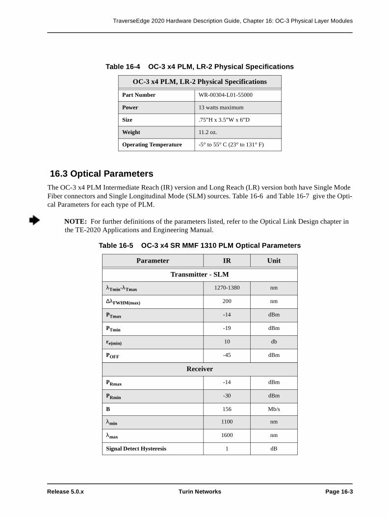
TraverseEdge 2020 Hardware Description Guide, Chapter 16: OC-3 Physical Layer Modules
Release 5.0.x Turin Networks Page 16-3
16.3 Optical ParametersThe OC-3 x4 PLM Intermediate Reach (IR) version and Long Reach (LR) version both have Single Mode Fiber connectors and Single Longitudinal Mode (SLM) sources. Table 16-6 and Table 16-7 give the Opti-cal Parameters for each type of PLM.
NOTE: For further definitions of the parameters listed, refer to the Optical Link Design chapter in the TE-2020 Applications and Engineering Manual.
Table 16-4 OC-3 x4 PLM, LR-2 Physical Specifications
OC-3 x4 PLM, LR-2 Physical Specifications
Part Number WR-00304-L01-55000
Power 13 watts maximum
Size .75”H x 3.5”W x 6”D
Weight 11.2 oz.
Operating Temperature -5° to 55° C (23° to 131° F)
Table 16-5 OC-3 x4 SR MMF 1310 PLM Optical Parameters
Parameter IR Unit
Transmitter - SLM
λTmin-λTmax 1270-1380 nm
∆λFWHM(max) 200 nm
PTmax -14 dBm
PTmin -19 dBm
re(min) 10 db
POFF -45 dBm
Receiver
PRmax -14 dBm
PRmin -30 dBm
B 156 Mb/s
λmin 1100 nm
λmax 1600 nm
Signal Detect Hysteresis 1 dB

TraverseEdge 2020 Hardware Description Guide, Chapter 16: OC-3 Physical Layer Modules
Page 16-4 Turin Networks Release 5.0.x
Table 16-6 OC-3 x4 IR Optical Parameters
Parameter IR Unit
Transmitter - SLM
λTmin-λTmax 1261-1360 nm
∆λrms(max) 4 nm
∆λ20(max) N/A nm
SSRmin N/A dB
PTmax -8 dBm
PTmin -15 dBm
re(min) 10 db
Optical Path
System ORLmin NA dB
DSR(max) NA ps/nm
Attenuation 0-13 dB
Max. Reflectance between S and R NA dB
Receiver
PRmax -8 dBm
PRmin -28 dBm
PO 1 dB
Receiver Reflectance (max) NA dB

TraverseEdge 2020 Hardware Description Guide, Chapter 16: OC-3 Physical Layer Modules
Release 5.0.x Turin Networks Page 16-5
16.4 Functional DescriptionThe OC-3 x4 PLM provides the following system level functions to the TE-2020.
• Four OC-3, 1310 nm or 1550 nm Optical User interfaces• Single-mode and Multi-mode fiber application (OC-3 x4 SR MMF 1320)
• CCT Connector• Five LEDs to indicate Card and Port Status
• SONET/SDH framing functions• O/E and E/O conversion
• Clock recovery and clock generation
16.5 Connectorization
Table 16-7 OC-3 x4 LR-1 Optical Parameters
Parameter LR-1 LR-2 Unit
Transmitter - SLM
λTmin-λTmax 1280-1335 1500-1580 nm
∆λrms(max) 4 NA nm
∆λ20(max) 1 <1 nm
SSRmin 30 30 dB
PTmax 0 +3 dBm
PTmin -5 -2 dBm
re(min) 10 8.2 dB
Optical Path
System ORLmin NA 24 dB
DSR(max) NA 1600 ps/nm
Attenuation 10-29 12-27 dB
Max. Reflectance between S and R NA -27 dB
Receiver
PRmax -10 -9 dBm
PRmin -34 -28 dBm
PO 1 2 dB
Receiver Reflectance (max) NA -27 dB
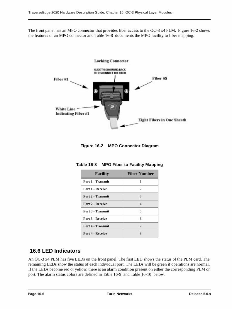
TraverseEdge 2020 Hardware Description Guide, Chapter 16: OC-3 Physical Layer Modules
Page 16-6 Turin Networks Release 5.0.x
The front panel has an MPO connector that provides fiber access to the OC-3 x4 PLM. Figure 16-2 shows the features of an MPO connector and Table 16-8 documents the MPO facility to fiber mapping.
Figure 16-2 MPO Connector Diagram
16.6 LED IndicatorsAn OC-3 x4 PLM has five LEDs on the front panel. The first LED shows the status of the PLM card. The remaining LEDs show the status of each individual port. The LEDs will be green if operations are normal. If the LEDs become red or yellow, there is an alarm condition present on either the corresponding PLM or port. The alarm status colors are defined in Table 16-9 and Table 16-10 below.
Table 16-8 MPO Fiber to Facility Mapping
Facility Fiber Number
Port 1 - Transmit 1
Port 1 - Receive 2
Port 2 - Transmit 3
Port 2 - Receive 4
Port 3 - Transmit 5
Port 3 - Receive 6
Port 4 - Transmit 7
Port 4 - Receive 8

TraverseEdge 2020 Hardware Description Guide, Chapter 16: OC-3 Physical Layer Modules
Release 5.0.x Turin Networks Page 16-7
16.7 CCT ConnectorsThe CCT connector on the leading edge (inserted first in the PLM slot) provides power as well as data and management connectivity between the CCTs and the PLMs.
Table 16-9 Port LED Behavior
Representation Port LED Behavior
Critical or Major Alarm Condition Red
Minor Alarm Condition Yellow
Loopback Flashing Yellow
Normal, No Alarm Conditions Green
No Power, Out-of-Service Off
Table 16-10 PLM Status LED Behavior
Representation Status LED Behavior
Board Failure Red
Normal Green
No Power, Out-of-Service Off

TraverseEdge 2020 Hardware Description Guide, Chapter 16: OC-3 Physical Layer Modules
Page 16-8 Turin Networks Release 5.0.x

Release 5.0.x Turin Networks Page 17-1
Chapter 17 GbE Physical Layer Modules
The MM or SM GbE x2 PLM is a two port plug-in module that can be used in either the TE-2020 Main Shelf or the OTS2 shelf. The GbE x2 PLM must be installed in a CCT that has already been installed in the shelf. The GbE x2 PLM provides the following functionality and connectivity:
• Two GbE (850, 1310, or 1550 nm) optical user interfaces• Multi Mode or Single Mode applications
• A single MPO connector for both interfaces• Ejector handles for card installation and removal
• CCT connector• Five LEDs to indicate Card and Port Status and Activity
• SONET/SDH framing functions• O/E and E/O conversion
• Ethernet Over SONET (EOS) mapping• 4ms differential delay
• Optional Layer 2 VLAN switching capability• Per port mapping to STS-1, STS-3c, STS-12c, STS-1-Xv (X=1-21), or STS3c-Xv (X=1-7)
• Per port policing and shaping (on Enhanced PLM only)• 22 WAN side interfaces (Enhanced PLM only)
Figure 17-1 GbE x2 PLM
17.1 ConfigurationsThe GbE x2 PLM operates unprotected. Consult the TE-2020 Applications and Engineering Manual (WR-D2020-APP-040000) for configuration details.
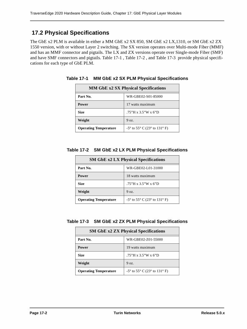
TraverseEdge 2020 Hardware Description Guide, Chapter 17: GbE Physical Layer Modules
Page 17-2 Turin Networks Release 5.0.x
17.2 Physical SpecificationsThe GbE x2 PLM is available in either a MM GbE x2 SX 850, SM GbE x2 LX,1310, or SM GbE x2 ZX 1550 version, with or without Layer 2 switching. The SX version operates over Multi-mode Fiber (MMF) and has an MMF connector and pigtails. The LX and ZX versions operate over Single-mode Fiber (SMF) and have SMF connectors and pigtails. Table 17-1 , Table 17-2 , and Table 17-3 provide physical specifi-cations for each type of GbE PLM.
Table 17-1 MM GbE x2 SX PLM Physical Specifications
MM GbE x2 SX Physical Specifications
Part No. WR-GBE02-S01-85000
Power 17 watts maximum
Size .75”H x 3.5”W x 6”D
Weight 9 oz.
Operating Temperature -5° to 55° C (23° to 131° F)
Table 17-2 SM GbE x2 LX PLM Physical Specifications
SM GbE x2 LX Physical Specifications
Part No. WR-GBE02-L01-31000
Power 18 watts maximum
Size .75”H x 3.5”W x 6”D
Weight 9 oz.
Operating Temperature -5° to 55° C (23° to 131° F)
Table 17-3 SM GbE x2 ZX PLM Physical Specifications
SM GbE x2 ZX Physical Specifications
Part No. WR-GBE02-Z01-55000
Power 19 watts maximum
Size .75”H x 3.5”W x 6”D
Weight 9 oz.
Operating Temperature -5° to 55° C (23° to 131° F)

TraverseEdge 2020 Hardware Description Guide, Chapter 17: GbE Physical Layer Modules
Release 5.0.x Turin Networks Page 17-3
Table 17-4 SM GbE x2 SX Enhanced PLM Physical Specifications
SM GbE x2 SX Enh Physical Specifications
Part No. WR-GBE02-S11-8500
Power 15 watts maximum
Size .75”H x 3.5”W x 6”D
Weight 9 oz.
Operating Temperature -5° to 55° C (23° to 131° F)
Table 17-5 SM GbE x2 LX Enhanced PLM Physical Specifications
SM GbE x2 LX Enh Physical Specifications
Part No. WR-GBE02-L11-3100
Power 17 watts maximum
Size .75”H x 3.5”W x 6”D
Weight 9 oz.
Operating Temperature -5° to 55° C (23° to 131° F)
Table 17-6 SM GbE x2 ZX Enhanced PLM Physical Specifications
SM GbE x2 ZX Enh Physical Specifications
Part No. WR-GBE02-Z11-5500
Power 17 watts maximum
Size .75”H x 3.5”W x 6”D
Weight 9 oz.
Operating Temperature -5° to 55° C (23° to 131° F)

TraverseEdge 2020 Hardware Description Guide, Chapter 17: GbE Physical Layer Modules
Page 17-4 Turin Networks Release 5.0.x
17.3 Optical ParametersThe MM GbE x2 SX version has an MMF connector. The SM GbE x2 LX and SM GbE ZX versions have SMF connectors and pigtails. Refer to Table 17-7 , Table 17-8 , and Table 17-9 for each GbE x2 PLM’s optical specifications.
NOTE: For further definitions of the parameters listed, refer to the Optical Link Design chapter in the TE-2020 Applications and Engineering Manual.
* Modal Bandwidth = 200 MHz • km
** Modal Bandwidth = 500 MHz • km
Table 17-7 MM GbE x2 SX (850 nm) Optical Specifications
Parameter GbE-SX Unit
62.5 µm MMF*
50 µm MMF**
Transmitter MLM
λTmin- λTmax 830-860 nm
λrms(max) 0.85 nm
PTmax -4 dBm
PTmin -10.5 dBm
Re(min) 9 dBm
Optical Path
System ORLmin 12 dB
DSR(max) N/A ps/nm
Attenuation 2.53 3.43 dB
Receiver
PRmax -3 dBm
PRmin -17 dBm
PO 1 dB
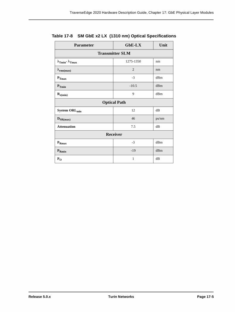
TraverseEdge 2020 Hardware Description Guide, Chapter 17: GbE Physical Layer Modules
Release 5.0.x Turin Networks Page 17-5
Table 17-8 SM GbE x2 LX (1310 nm) Optical Specifications
Parameter GbE-LX Unit
Transmitter SLM
λTmin- λTmax 1275-1350 nm
λrms(max) 2 nm
PTmax -3 dBm
PTmin -10.5 dBm
Re(min) 9 dBm
Optical Path
System ORLmin 12 dB
DSR(max) 46 ps/nm
Attenuation 7.5 dB
Receiver
PRmax -3 dBm
PRmin -19 dBm
PO 1 dB

TraverseEdge 2020 Hardware Description Guide, Chapter 17: GbE Physical Layer Modules
Page 17-6 Turin Networks Release 5.0.x
.
17.4 Functional DescriptionThe GbE x2 PLMs provide the following functions:
• Two GbE (850, 1310, or 1550 nm) optical user interfaces• A single MPO connector for both interfaces
• CCT Connector• Five LEDs to indicate Card and Port status, and Activity
• Ethernet Over SONET (EOS) mapping• SONET/SDH framing functions
• O/E and E/O conversion• Ejector handles for card installation and removal
• Optional Layer 2 switching capability
17.5 ConnectorizationThe front panel has an MPO connector that provides fiber access to the GbE x2 PLM. Figure 17-2 shows the features of an MPO connector and Table 17-10 documents the MPO facility to fiber mapping.
Table 17-9 SM GbE x2 ZX (1550 nm) Optical Specifications
Parameter GbE-ZX Unit
Transmitter SLM
λTmin- λTmax 1540-1570 nm
λ20(max) 1 nm
SSRmin 30
PTmax 2 dBm
PTmin -4 dBm
Re(min) 7 dBm
Optical Path
System ORLmin 12 dB
DSR(max) 1486 ps/nm
Attenuation 19.5 dB
Receiver
PRmax -1 dBm
PRmin -24.5 dBm
PO 1 dB

TraverseEdge 2020 Hardware Description Guide, Chapter 17: GbE Physical Layer Modules
Release 5.0.x Turin Networks Page 17-7
Figure 17-2 MPO Connector Diagram
17.6 LED IndicatorsAn GbE x2 PLM has five LEDs on the front panel. The first LED shows the status of the PLM card. For each port, one LED shows the status of the port and one LED indicates port activity. The PLM and Port Status LEDs will be green if operations are normal. If these LEDs become red or yellow, there is an alarm condition present on either the corresponding PLM or port. The alarm status colors are defined in Table 17-11 and Table 17-12 . The Activity LED for each port flashes green at a rate proportionate to the received Ethernet frame rate on that port.
Table 17-10 MPO Fiber to Facility Mapping
Facility Fiber Number
Port 1 - Transmit 1
Port 1 - Receive 2
Port 2 - Transmit 3
Port 2 - Receive 4

TraverseEdge 2020 Hardware Description Guide, Chapter 17: GbE Physical Layer Modules
Page 17-8 Turin Networks Release 5.0.x
17.7 CCT ConnectorsThe CCT connector on the leading edge (inserted first in the PLM slot) provides power as well as data and management connectivity between the CCTs and the PLMs.
17.8 VLAN CapabilityThe Enhanced GbE module supports up to 4096 VLANs per port. Please refer to the Applications Engi-neering Manual for additional information.
Table 17-11 Port LED Behavior
Representation Port LED Behavior
Critical or Major Alarm Condition Red
Minor Alarm Condition Yellow
Loopback Flashing Yellow
Normal, No Alarm Conditions Green
No Power, Out-of-Service Off
Table 17-12 PLM Status LED Behavior
Representation Status LED Behavior
Board Failure Red
Normal Green
No Power, Out-of-Service Off

Release 5.0.x Turin Networks Page 18-1
Chapter 18 DS3/EC1 Physical Layer Modules
The DS3/EC1 Physical Layer Module (PLM) is a 12 port plug-in module that can be used in the ETS1 or ETS2 (part number dependant) and provides the user with test access ports on the faceplate. There are three part numbers available, the first (WR-DS312-001-00000) has non-intrusive monitor ports and can be used only in the ETS1 shelf. The second (WR-DS312-011-00000) has intrusive test access ports and can be used in either shelf. The third version supports multiplexing for VT cross connects and is called the DS3 TransMux or TMUX (WR-DS312-T11-00000). The DS3 TMUX also has intrusive test access ports and can be used in either shelf. All versions of this card provide the following functionality and connectivity:
• 12 x DS3/EC-1 electrical interfaces that are per port configurable• Ejector handles for card installation and removal
• DS3/EC-1 Monitor Port and selector • 13 LEDs to indicate Card and Port Status
• DS3 to SONET mapping functions• SONET framing functions
• Test or Monitor Front Panel Access (card dependent)• Test Access LED (card dependent)
Figure 18-1 DS3/EC1 x12 PLM
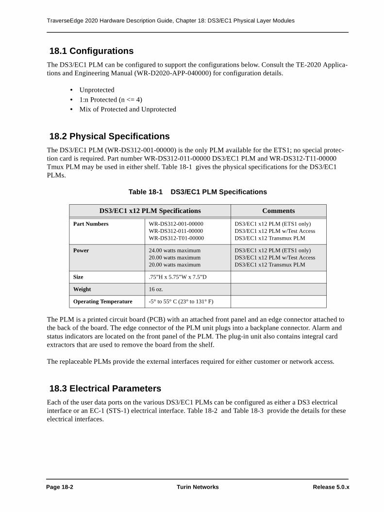
TraverseEdge 2020 Hardware Description Guide, Chapter 18: DS3/EC1 Physical Layer Modules
Page 18-2 Turin Networks Release 5.0.x
18.1 ConfigurationsThe DS3/EC1 PLM can be configured to support the configurations below. Consult the TE-2020 Applica-tions and Engineering Manual (WR-D2020-APP-040000) for configuration details.
• Unprotected
• 1:n Protected (n <= 4)• Mix of Protected and Unprotected
18.2 Physical SpecificationsThe DS3/EC1 PLM (WR-DS312-001-00000) is the only PLM available for the ETS1; no special protec-tion card is required. Part number WR-DS312-011-00000 DS3/EC1 PLM and WR-DS312-T11-00000 Tmux PLM may be used in either shelf. Table 18-1 gives the physical specifications for the DS3/EC1 PLMs.
Table 18-1 DS3/EC1 PLM Specifications
The PLM is a printed circuit board (PCB) with an attached front panel and an edge connector attached to the back of the board. The edge connector of the PLM unit plugs into a backplane connector. Alarm and status indicators are located on the front panel of the PLM. The plug-in unit also contains integral card extractors that are used to remove the board from the shelf.
The replaceable PLMs provide the external interfaces required for either customer or network access.
18.3 Electrical ParametersEach of the user data ports on the various DS3/EC1 PLMs can be configured as either a DS3 electrical interface or an EC-1 (STS-1) electrical interface. Table 18-2 and Table 18-3 provide the details for these electrical interfaces.
DS3/EC1 x12 PLM Specifications Comments
Part Numbers WR-DS312-001-00000WR-DS312-011-00000WR-DS312-T01-00000
DS3/EC1 x12 PLM (ETS1 only)DS3/EC1 x12 PLM w/Test AccessDS3/EC1 x12 Transmux PLM
Power 24.00 watts maximum20.00 watts maximum20.00 watts maximum
DS3/EC1 x12 PLM (ETS1 only)DS3/EC1 x12 PLM w/Test AccessDS3/EC1 x12 Transmux PLM
Size .75”H x 5.75”W x 7.5”D
Weight 16 oz.
Operating Temperature -5° to 55° C (23° to 131° F)

TraverseEdge 2020 Hardware Description Guide, Chapter 18: DS3/EC1 Physical Layer Modules
Release 5.0.x Turin Networks Page 18-3
Table 18-2 DS3 Port Specifications
Table 18-3 EC-1 Port Specifications
18.4 LED IndicatorsA DS3/EC1 PLM has 14 LEDs on the front panel. The upper left LED shows the status of the PLM card. and lower left indicates a facility or terminal selection via a port selector button. The remaining 12 LEDs show the status of each individual port. The LEDs will be green if operations are normal. If the LEDs become red or yellow, there is an alarm condition present on either the corresponding PLM or port. The alarm status colors are defined in Table 18-4 , Table 18-5 , and Table 18-6 .
Table 18-4 Port LED Behavior
DS3 Port Specifications
Bit Rate 44.736 Mb/s +/- 20ppm
Framing DS3 - ANSI T1.107
Line Code B3ZS
Input Impedance 75 Ohms
Power Level -1.8 to 5.7 dBm
Pulse Amplitude 0.36 to 0.85 Volts Peak to Peak
Line Build Out 0-225 ft.225-450 ft.
EC-1 Port Specifications
Bit Rate 51.84 Mb/s +/- 20ppm
Framing SONET
Line Code B3ZS
Input Impedance 75 Ohms
Power Level -1.8 to 5.7 dBm
Pulse Amplitude 0.36 to 0.85 Volts Peak to Peak
Line Build Out 0 to 225 ft.225 to 450 ft.
Representation LED Behavior
Critical or Major Alarm Condition Red
Minor Alarm Condition Yellow
Loopback Flashing Yellow
Normal, No Alarm Conditions Green
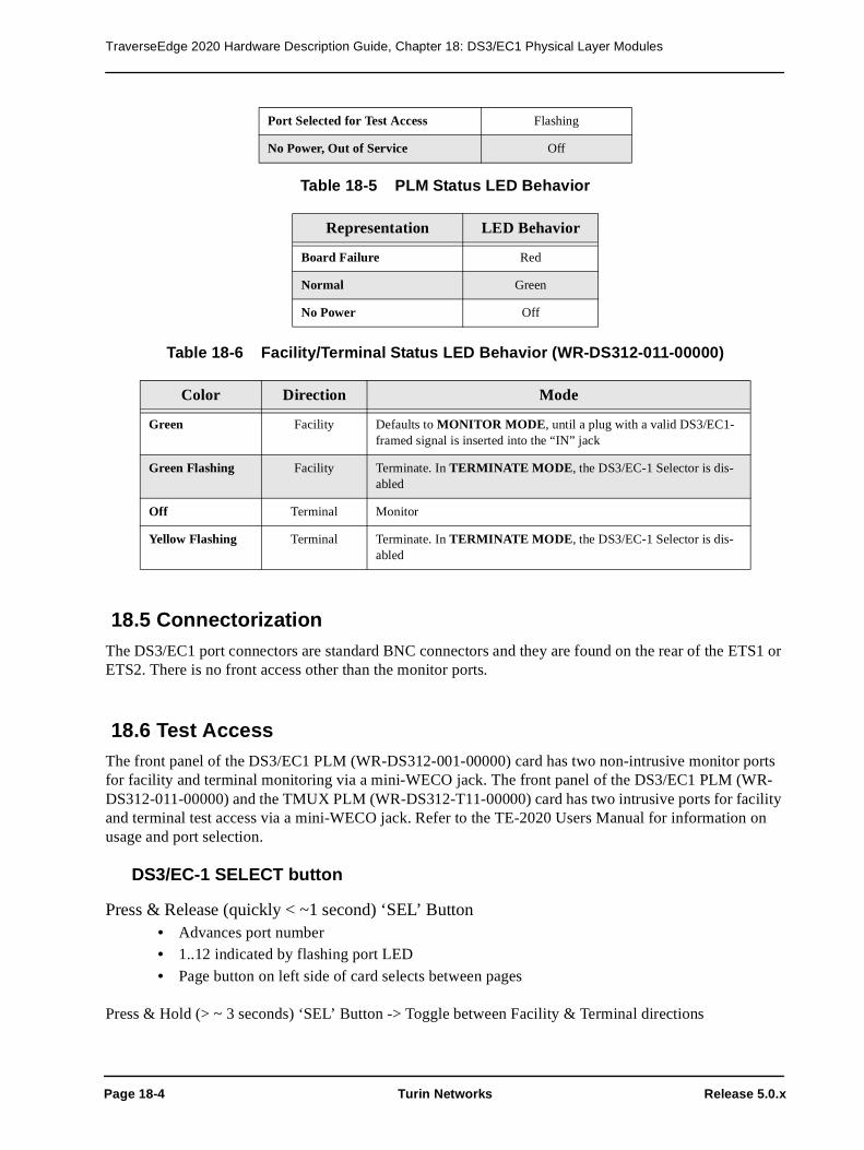
TraverseEdge 2020 Hardware Description Guide, Chapter 18: DS3/EC1 Physical Layer Modules
Page 18-4 Turin Networks Release 5.0.x
Table 18-5 PLM Status LED Behavior
Table 18-6 Facility/Terminal Status LED Behavior (WR-DS312-011-00000)
18.5 ConnectorizationThe DS3/EC1 port connectors are standard BNC connectors and they are found on the rear of the ETS1 or ETS2. There is no front access other than the monitor ports.
18.6 Test AccessThe front panel of the DS3/EC1 PLM (WR-DS312-001-00000) card has two non-intrusive monitor ports for facility and terminal monitoring via a mini-WECO jack. The front panel of the DS3/EC1 PLM (WR-DS312-011-00000) and the TMUX PLM (WR-DS312-T11-00000) card has two intrusive ports for facility and terminal test access via a mini-WECO jack. Refer to the TE-2020 Users Manual for information on usage and port selection.
DS3/EC-1 SELECT button
Press & Release (quickly < ~1 second) ‘SEL’ Button• Advances port number• 1..12 indicated by flashing port LED
• Page button on left side of card selects between pages
Press & Hold (> ~ 3 seconds) ‘SEL’ Button -> Toggle between Facility & Terminal directions
Port Selected for Test Access Flashing
No Power, Out of Service Off
Representation LED Behavior
Board Failure Red
Normal Green
No Power Off
Color Direction Mode
Green Facility Defaults to MONITOR MODE, until a plug with a valid DS3/EC1-framed signal is inserted into the “IN” jack
Green Flashing Facility Terminate. In TERMINATE MODE, the DS3/EC-1 Selector is dis-abled
Off Terminal Monitor
Yellow Flashing Terminal Terminate. In TERMINATE MODE, the DS3/EC-1 Selector is dis-abled
TraverseEdge 2020 Hardware Description Guide, Chapter 18: DS3/EC1 Physical Layer Modules
Release 5.0.x Turin Networks Page 18-5
Test Access Type
Determined by presence/no-presence of signal on ‘IN’ jack
• Test Cable present with signal = Terminate• Test Cable present no signal = Monitor
• Test Cable not present = Monitor
With a test test cable inserted with a signal in the IN jack, and terminating a signal on Channel X, the SEL button is disabled for port selection but FAC button still enabled to switch direction. Signal removal returns the test port to monitor only functionality, and re-enables the SEL button again.
Figure 18-2 DS3/EC-1 Passive Monitoring Ports
Figure 18-3 DS3/EC-1 Test Access Ports
18.7 SONET Framing and MappingFor a DS3 signal, the incoming electrical signal is terminated by a Line Interface Unit and the digital DS3 signal is mapped into a SONET STS-1. For an EC-1 signal, the incoming electrical signal is terminated by a Line Interface Unit and the digital STS-1 signal is framed. The STS-1 (from either the DS3 or EC-1) is mapped into an STS-12 and sent to the CCT to be mapped into an STS-48 for transmission over the LEI.

TraverseEdge 2020 Hardware Description Guide, Chapter 18: DS3/EC1 Physical Layer Modules
Page 18-6 Turin Networks Release 5.0.x
The preceding functions are performed in reverse order on transmit.
18.8 DS3 TMUXThe DS3 TMUX enables the user to configure VT mapping on any individual DS3 port. This unit can accept any DS3 with 28 DS1 framing and convert it into VT1.5 framing from either the high speed or cable entry from the interconnect backplane. If needed the user can configure two ports to work as a pair for this conversion without utilizing the interconnect backplane (i.e., signal from highspeed enters one port as an STS-1 x28 DS1s and exits its partner port as an STS-1 x 28VT1.5s). The TMUX has no limitations other than if a protect unit is available then it must be a TMUX version. A standard DS3 PLM cannot protect a DS3 TMUX PLM but the TMUX PLM can provide protection for any of the DS3 PLMs.
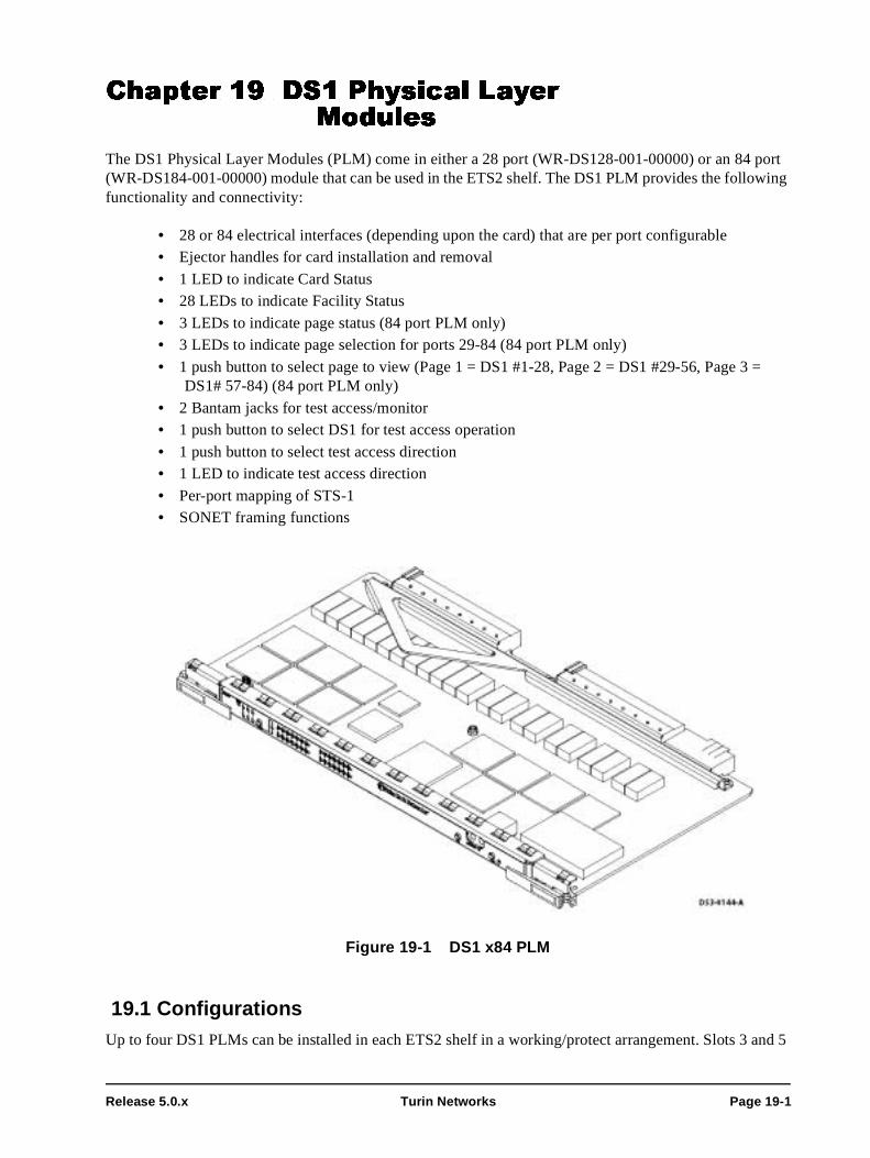
Release 5.0.x Turin Networks Page 19-1
Chapter 19 DS1 Physical Layer Modules
The DS1 Physical Layer Modules (PLM) come in either a 28 port (WR-DS128-001-00000) or an 84 port (WR-DS184-001-00000) module that can be used in the ETS2 shelf. The DS1 PLM provides the following functionality and connectivity:
• 28 or 84 electrical interfaces (depending upon the card) that are per port configurable• Ejector handles for card installation and removal
• 1 LED to indicate Card Status• 28 LEDs to indicate Facility Status
• 3 LEDs to indicate page status (84 port PLM only)• 3 LEDs to indicate page selection for ports 29-84 (84 port PLM only)
• 1 push button to select page to view (Page 1 = DS1 #1-28, Page 2 = DS1 #29-56, Page 3 = DS1# 57-84) (84 port PLM only)
• 2 Bantam jacks for test access/monitor • 1 push button to select DS1 for test access operation
• 1 push button to select test access direction • 1 LED to indicate test access direction
• Per-port mapping of STS-1• SONET framing functions
Figure 19-1 DS1 x84 PLM
19.1 ConfigurationsUp to four DS1 PLMs can be installed in each ETS2 shelf in a working/protect arrangement. Slots 3 and 5
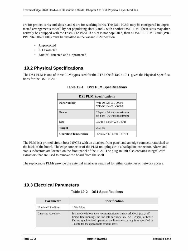
TraverseEdge 2020 Hardware Description Guide, Chapter 19: DS1 Physical Layer Modules
Page 19-2 Turin Networks Release 5.0.x
are for protect cards and slots 4 and 6 are for working cards. The DS1 PLMs may be configured in unpro-tected arrangements as well by not populating slots 3 and 5 with another DS1 PLM. These slots may alter-natively be equipped with the FastE x12 PLM. If a slot is not populated, then a DS1/FE PLM Blank (WR-PBLNK-006-00000) must be installed in the vacant PLM position.
• Unprotected• 1:1 Protected
• Mix of Protected and Unprotected
19.2 Physical SpecificationsThe DS1 PLM is one of three PLM types card for the ETS2 shelf. Table 19-1 gives the Physical Specifica-tions for the DS1 PLM.
Table 19-1 DS1 PLM Specifications
The PLM is a printed circuit board (PCB) with an attached front panel and an edge connector attached to the back of the board. The edge connector of the PLM unit plugs into a backplane connector. Alarm and status indicators are located on the front panel of the PLM. The plug-in unit also contains integral card extractors that are used to remove the board from the shelf.
The replaceable PLMs provide the external interfaces required for either customer or network access.
19.3 Electrical ParametersTable 19-2 DS1 Specifications
DS1 PLM Specifications
Part Number WR-DS128-001-00000 WR-DS184-001-00000
Power 28-port - 20 watts maximum84-port - 36 watts maximum
Size .75”H x 14.65”W x 7.5”D
Weight 20.8 oz.
Operating Temperature -5° to 55° C (23° to 131° F)
Parameter Specification
Nominal Line Rate 1.544 Mb/s
Line-rate Accuracy In a mode without any synchronization to a network clock (e.g., self timed, free-running), the line-rate accuracy is 50 b/s (32 ppm) or better. During synchronized operation, the line-rate accuracy is as specified in T1.101 for the appropriate stratum level.

TraverseEdge 2020 Hardware Description Guide, Chapter 19: DS1 Physical Layer Modules
Release 5.0.x Turin Networks Page 19-3
19.4 LED IndicatorsA DS1 x28 PLM has 30 LEDs on the front panel. A DS1 x84 PLM has 35 LEDs on the front panel.The first LED shows the status of the PLM card and is called STAT. 28 LEDs show the status of each individual port on card. The LEDs will be green if operations are normal. If the LEDs become red or yellow, there is an alarm condition present on either the corresponding PLM or port.
On DS1 x84 PLMs, the 84 DS1s are separated into groups or pages of 28 ports. Page 1 represents DS1 #1 through DS1 #28, Page 2 represents DS1 #29 through DS1 #56, and Page 3 represents DS1 #57 through DS1 #84. The upper 3 Page LEDs indicate the highest level alarm status of the DS1s on each of the 3 pages. The lower 3 Page LEDs indicate the page the user is viewing with the 28 individual DS1 status LEDs. When viewing Page 1, the user can scroll through ports 1 through 28 using the test access DS1 selector button. When viewing Page 2, the user can scroll through ports 29 through 56. When viewing Page 3, the user can scroll through ports 57 through 84. The alarm status colors are defined in Table 19-3 .
Figure 19-2 DS1 x84 PLM Port LEDs
Line Code Either (1) AMI with no more than 15 consecutive zeros, and at least N ones in each and every time window of 8(N + 1) digit time slots (where N can range from 1 to 23), or (2) B8ZS.
Frame Structure No frame structure is required for DS1 transmission or higher level multi-plexing to higher DSN signals or to SONET payloads.
Pulse Amplitude The amplitude of an isolated pulse is between 2.4 V and 3.6 V.
Power Level For an all-ones signal, the power in a 3-kHz (1 kHz) band centered at 772 kHz is between 12.6 and 17.9 dBm. The power in a 3-kHz (1 kHz) band centered at 1544 kHz is at least 29 dB below that at 772 kHz.
Parameter Specification
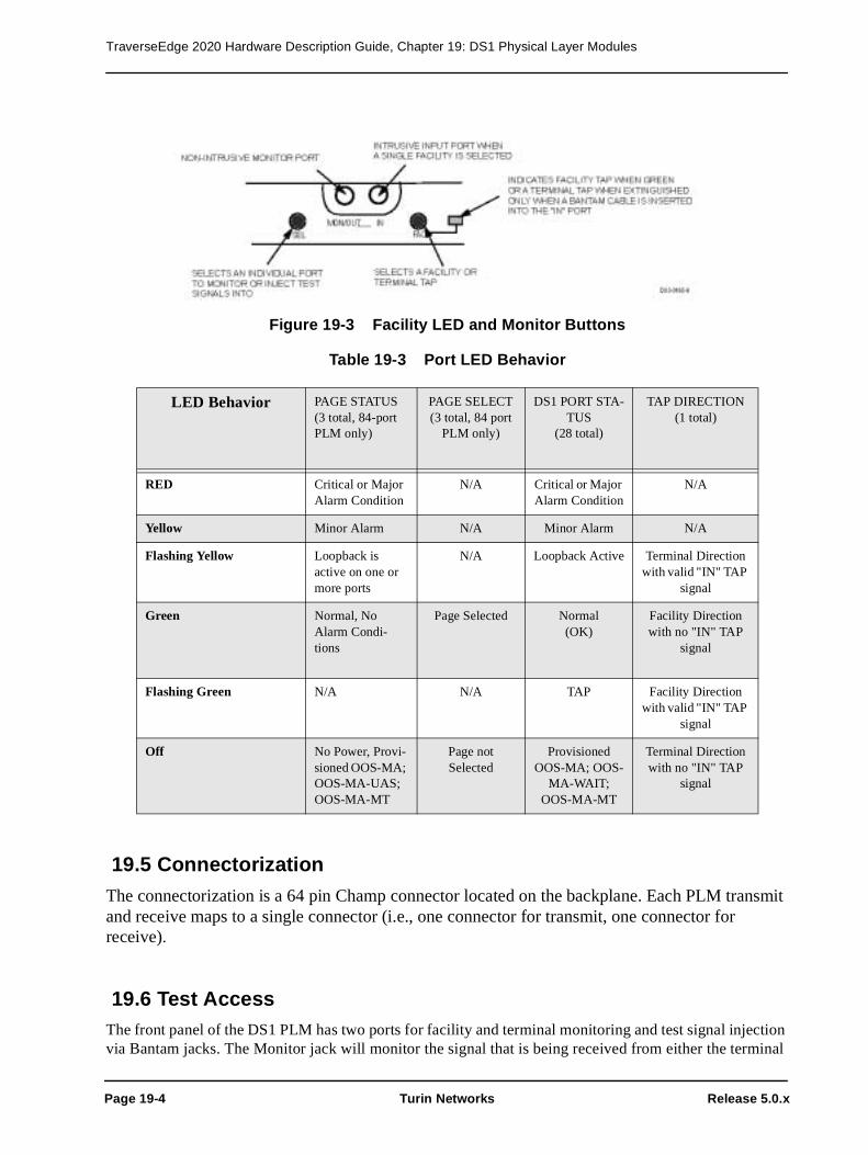
TraverseEdge 2020 Hardware Description Guide, Chapter 19: DS1 Physical Layer Modules
Page 19-4 Turin Networks Release 5.0.x
Figure 19-3 Facility LED and Monitor Buttons
Table 19-3 Port LED Behavior
19.5 ConnectorizationThe connectorization is a 64 pin Champ connector located on the backplane. Each PLM transmit and receive maps to a single connector (i.e., one connector for transmit, one connector for receive).
19.6 Test AccessThe front panel of the DS1 PLM has two ports for facility and terminal monitoring and test signal injection via Bantam jacks. The Monitor jack will monitor the signal that is being received from either the terminal
LED Behavior PAGE STATUS(3 total, 84-port PLM only)
PAGE SELECT(3 total, 84 port
PLM only)
DS1 PORT STA-TUS
(28 total)
TAP DIRECTION(1 total)
RED Critical or Major Alarm Condition
N/A Critical or Major Alarm Condition
N/A
Yellow Minor Alarm N/A Minor Alarm N/A
Flashing Yellow Loopback is active on one or more ports
N/A Loopback Active Terminal Directionwith valid "IN" TAP
signal
Green Normal, No Alarm Condi-tions
Page Selected Normal(OK)
Facility Directionwith no "IN" TAP
signal
Flashing Green N/A N/A TAP Facility Directionwith valid "IN" TAP
signal
Off No Power, Provi-sioned OOS-MA; OOS-MA-UAS; OOS-MA-MT
Page not Selected
Provisioned OOS-MA; OOS-
MA-WAIT; OOS-MA-MT
Terminal Directionwith no "IN" TAP
signal

TraverseEdge 2020 Hardware Description Guide, Chapter 19: DS1 Physical Layer Modules
Release 5.0.x Turin Networks Page 19-5
(high speed or trunk) or the facility (low speed or tributary) side depending on the user selection. If the FAC LED is lit then the facility side is being monitored. If extinguish, the card defaults to the terminal side. Refer to the TE-2020 Users Manual (WR-D2020-USR-040000) for information on usage and port selection.
The SEL button selects the port to be monitored or accessed. When pushed, the first LED of the Page selected will light and each additional selection will scroll through the 28 LEDs. For 84 Port DS1 PLMs, the Page select button must be used to move to the next 28 port selection.
Figure 19-4 DS1 Test Access

TraverseEdge 2020 Hardware Description Guide, Chapter 19: DS1 Physical Layer Modules
Page 19-6 Turin Networks Release 5.0.x
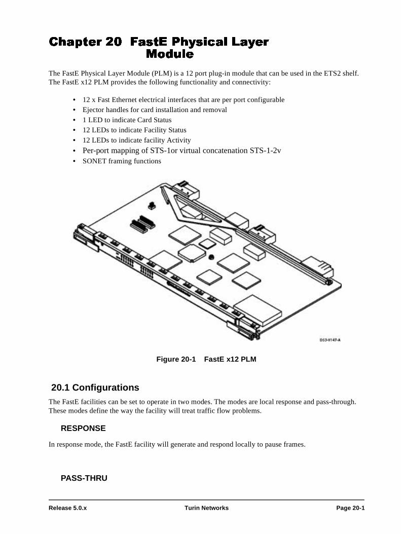
Release 5.0.x Turin Networks Page 20-1
Chapter 20 FastE Physical Layer Module
The FastE Physical Layer Module (PLM) is a 12 port plug-in module that can be used in the ETS2 shelf. The FastE x12 PLM provides the following functionality and connectivity:
• 12 x Fast Ethernet electrical interfaces that are per port configurable• Ejector handles for card installation and removal
• 1 LED to indicate Card Status• 12 LEDs to indicate Facility Status
• 12 LEDs to indicate facility Activity
• Per-port mapping of STS-1or virtual concatenation STS-1-2v• SONET framing functions
Figure 20-1 FastE x12 PLM
20.1 ConfigurationsThe FastE facilities can be set to operate in two modes. The modes are local response and pass-through. These modes define the way the facility will treat traffic flow problems.
RESPONSE
In response mode, the FastE facility will generate and respond locally to pause frames.
PASS-THRU

TraverseEdge 2020 Hardware Description Guide, Chapter 20: FastE Physical Layer Module
Page 20-2 Turin Networks Release 5.0.x
In the pass-through mode of operation, the FastE facility will not respond to Pause frames. The system acts like a pipe and allows other equipment to generate and respond to pause frames. The pause frames generated by other equipment will pass transparently through this system for equip-ment at the far end to respond to.
AUTO NEGOTIATION
Auto-Negotiation provides a Fast Ethernet device with the capability to detect the abilities (modes of oper-ation) supported by the device at the other end of a link segment, determine common abilities, and config-ure for joint operation. Auto-Negotiation is performed upon link startup with a special sequence of reserved link code words.
The Auto-Negotiation function is provided at the physical convergence sub-layer. Devices that support multiple modes of operation may advertise this fact using this function. The transfer of information is observable only at the media dependence interface or on the medium.
Auto-Negotiation does not perform cable tests, such as cable performance measurements
Table 20-1 Ethernet Modes Supported
LAN Support
One very important requirement from the LAN side is for 'wire speed' support. Wire speed sup-port means the device can handle the 100 Mbps traffic regardless of the frame size. The smaller the frame size the more frames need to be processed. The FastE PLM is able to handle the wire speed for all 64 bytes (the minimum Ethernet frame size).
20.2 Physical SpecificationsThe FastE x12 PLM is the one of three port cards available or the ETS2 shelf; no protection card is required for FastE. The PLM is a printed circuit board (PCB) with an attached front panel and an edge con-nector attached to the back of the board. The edge connector of the PLM unit plugs into a backplane con-nector. Alarm and status indicators are located on the front panel of the PLM. The plug-in unit also contains integral card extractors that are used to remove the board from the shelf.
The replaceable PLMs provide the external interfaces required for either customer or network access. Table 20-1 gives the Physical Specifications for the FastE x12 PLM.
Rate Duplex
100 Full
100 Half
10 Full
10 Half
Auto Auto

TraverseEdge 2020 Hardware Description Guide, Chapter 20: FastE Physical Layer Module
Release 5.0.x Turin Networks Page 20-3
Table 20-2 FastE x12 PLM Specifications
20.3 Electrical ParametersThe FastE x12 PLM provides the following electrical features:
Line Side
• Complies with IEEE 802.3 10/100Base-T • Auto-MDI/MDIX crossover (automatic crossover correction for mis-wired cables)
• Reaches over 100 meters on category 5 cable [cat 5 cable calls out the impedance specs] • 16ms Differential Delay
SONET Side
• Supports bandwidth of up to 12 STS-1 SONET channels• Channels can be configured as either an STS-1 (50 Mbps) or STS-1-2v (100 Mbps)• Complies with the T1X1 specification (ANSI T1.105) of the H4 POH byte assignment for each of the VC STS-1-Nv links. (N=1-2).
NOTE: Channels supported only until the 622 Mbps of bandwidth has been utilized.
VC STS MAPPING REQUIREMENTS
In T1X1.5, two methods for concatenation are defined; contiguous and virtual concatenation. Both meth-ods provide concatenated bandwidth of X times the SPE payload capacity at the path termination. The dif-ference between these two approaches is the transport between the path terminations. Contiguous concatenation maintains the contiguous bandwidth through out the whole transport, while virtual concate-nation breaks the contiguous bandwidth into individual SPEs, transports the individual SPEs and recom-bines these SPEs to a contiguous bandwidth at the end point of the transmission. Virtual concatenation requires concatenation functionality only at the path termination equipment, while contiguous concatena-tion requires concatenation functionality at each network element.
Two types of virtual concatenations have been defined - High Order for STS-1-Xv SPE and Low Order XVTn SPE. The FastE PLM only supports HO STS-1-Xv type virtual concatenation in this release.
20.4 LED IndicatorsA FastE x12 PLM has 25 LEDs on the front panel. The first LED shows the status of the PLM card. 12
FastE x12 PLM Specifications
Part Number WR-FE012-001-00000
Power 20 watts maximum
Size .75”H x 14.65”W x 7.5”D
Weight 20.8 oz.
Operating Temperature -5° to 55° C (23° to 131° F)

TraverseEdge 2020 Hardware Description Guide, Chapter 20: FastE Physical Layer Module
Page 20-4 Turin Networks Release 5.0.x
LEDs show the status of each individual port and the remaining 12 LEDs indicate activity on each port. The status LEDs will be green if operations are normal. If the Status LEDs become red or yellow, there is an alarm condition present on either the corresponding PLM or port. If the activity LED for a port is off, and the port is in service with no alarms, then there is no activity on that port. The alarm status colors are defined in Table 20-3 .
Figure 20-2 Port LED Indictors
Table 20-3 Port Status LED Behavior
20.5 Connectorization
The connectorization standard for Fast Ethernet is typically RJ-45. Due to the large number of connections associated with FastE x12 PLM, it is not feasible to have RJ-45 connectorization on the shelf. The connectorization is through 50-pin mini-Telco (high-density) connectors located on the backplane. Each PLM maps to a single connector. Interconnect panels are available through Turin Networks. Refer to the TE-2020 Ordering Manual (WR-D2020-ORD-040000).
Representation LED Behavior
Critical or Major Alarm Condition Red
Normal, No Alarm Conditions Green
No Power, Out of Service Off
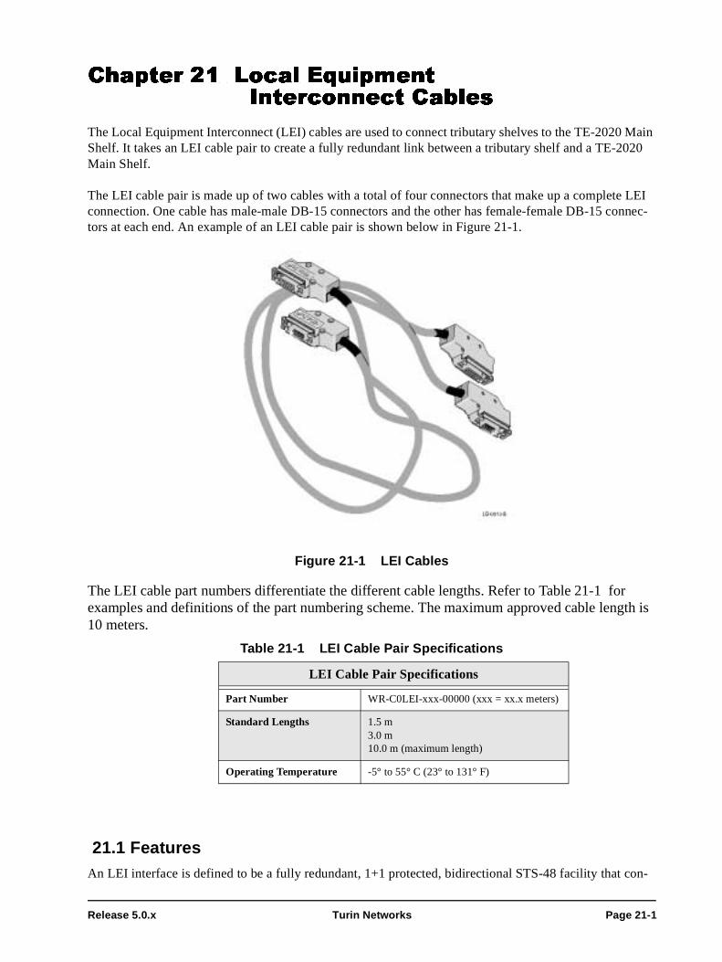
Release 5.0.x Turin Networks Page 21-1
Chapter 21 Local Equipment Interconnect Cables
The Local Equipment Interconnect (LEI) cables are used to connect tributary shelves to the TE-2020 Main Shelf. It takes an LEI cable pair to create a fully redundant link between a tributary shelf and a TE-2020 Main Shelf.
The LEI cable pair is made up of two cables with a total of four connectors that make up a complete LEI connection. One cable has male-male DB-15 connectors and the other has female-female DB-15 connec-tors at each end. An example of an LEI cable pair is shown below in Figure 21-1.
Figure 21-1 LEI Cables
The LEI cable part numbers differentiate the different cable lengths. Refer to Table 21-1 for examples and definitions of the part numbering scheme. The maximum approved cable length is 10 meters.
Table 21-1 LEI Cable Pair Specifications
21.1 FeaturesAn LEI interface is defined to be a fully redundant, 1+1 protected, bidirectional STS-48 facility that con-
LEI Cable Pair Specifications
Part Number WR-C0LEI-xxx-00000 (xxx = xx.x meters)
Standard Lengths 1.5 m3.0 m10.0 m (maximum length)
Operating Temperature -5° to 55° C (23° to 131° F)
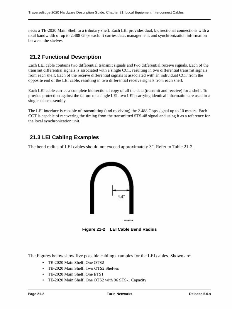
TraverseEdge 2020 Hardware Description Guide, Chapter 21: Local Equipment Interconnect Cables
Page 21-2 Turin Networks Release 5.0.x
nects a TE-2020 Main Shelf to a tributary shelf. Each LEI provides dual, bidirectional connections with a total bandwidth of up to 2.488 Gbps each. It carries data, management, and synchronization information between the shelves.
21.2 Functional DescriptionEach LEI cable contains two differential transmit signals and two differential receive signals. Each of the transmit differential signals is associated with a single CCT, resulting in two differential transmit signals from each shelf. Each of the receive differential signals is associated with an individual CCT from the opposite end of the LEI cable, resulting in two differential receive signals from each shelf.
Each LEI cable carries a complete bidirectional copy of all the data (transmit and receive) for a shelf. To provide protection against the failure of a single LEI, two LEIs carrying identical information are used in a single cable assembly.
The LEI interface is capable of transmitting (and receiving) the 2.488 Gbps signal up to 10 meters. Each CCT is capable of recovering the timing from the transmitted STS-48 signal and using it as a reference for the local synchronization unit.
21.3 LEI Cabling Examples
The bend radius of LEI cables should not exceed approximately 3”. Refer to Table 21-2 .
Figure 21-2 LEI Cable Bend Radius
The Figures below show five possible cabling examples for the LEI cables. Shown are:
• TE-2020 Main Shelf, One OTS2• TE-2020 Main Shelf, Two OTS2 Shelves
• TE-2020 Main Shelf, One ETS1• TE-2020 Main Shelf, One OTS2 with 96 STS-1 Capacity
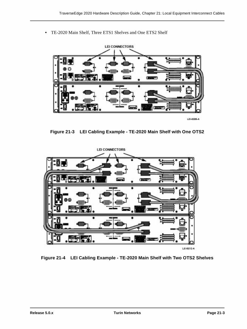
TraverseEdge 2020 Hardware Description Guide, Chapter 21: Local Equipment Interconnect Cables
Release 5.0.x Turin Networks Page 21-3
• TE-2020 Main Shelf, Three ETS1 Shelves and One ETS2 Shelf
Figure 21-3 LEI Cabling Example - TE-2020 Main Shelf with One OTS2
Figure 21-4 LEI Cabling Example - TE-2020 Main Shelf with Two OTS2 Shelves
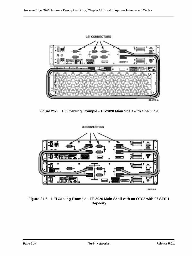
TraverseEdge 2020 Hardware Description Guide, Chapter 21: Local Equipment Interconnect Cables
Page 21-4 Turin Networks Release 5.0.x
Figure 21-5 LEI Cabling Example - TE-2020 Main Shelf with One ETS1
Figure 21-6 LEI Cabling Example - TE-2020 Main Shelf with an OTS2 with 96 STS-1 Capacity

TraverseEdge 2020 Hardware Description Guide, Chapter 21: Local Equipment Interconnect Cables
Release 5.0.x Turin Networks Page 21-5
Figure 21-7 LEI Cabling Example - TE-2020 Main Shelf with One OTS2 Shelf, One ETS1 Shelf, and One ETS2 Shelf

TraverseEdge 2020 Hardware Description Guide, Chapter 21: Local Equipment Interconnect Cables
Page 21-6 Turin Networks Release 5.0.x
Release 5.0.x Turin Networks Page 22-1
Chapter 22 Interface Cables
This section defines the pinouts for the interface cables that might be required for a TE-2020 node. If the TE-2020 node is configured with DS1 PLMs, or FastE PLMs, Turin Networks has terminated and untermi-nated DS1 interface cables and FastE interface cables available for purchase. In addition to these interface cables, DS3 BNC bundled cables are available for purchase. Refer to the TE-2020 Ordering Manual for details (WR-D2020-ORD-040000).
The following sections contain information and pinout descriptions for their associated interface cables:
22.1 User Interface Cables22.2 DS1 Interface Cables22.4 FastE Patch Panel Interconnect Cable22.5 LEI Interfaces
22.1 User Interface Cables
Two types of user interfaces are provided on the TE-2020 Main Shelf; the RJ45 front craft user and rear Ethernet interfaces, and the DB-9 rear craft user serial interface.
Physical Interfaces
• Front Craft Ethernet Port
• Dual rear Ethernet connections• Rear DB-9 RS-232 Craft User Port
22.1.1 Front RJ45 Craft User Port
The user can access an NE via an Ethernet port located on the front of the TE-2020 Main Fan Tray. Refer to Figure 22-1.
Figure 22-1 Craft User Port and Cable
This port uses a standard NAPT (Network Address Port Translation) which enables a user to connect to any Turin Networks TE-2020 Main Shelf without any additional IP configuration changes to the inter-
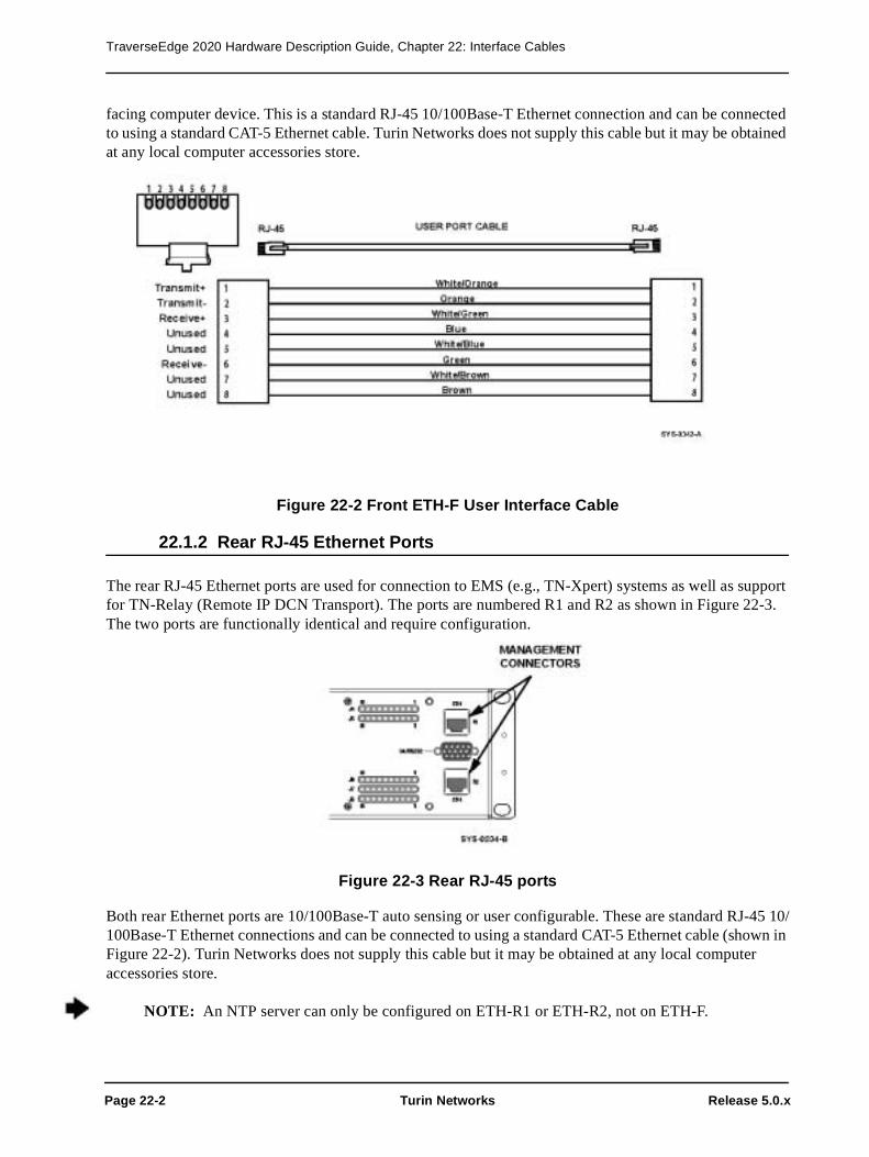
TraverseEdge 2020 Hardware Description Guide, Chapter 22: Interface Cables
Page 22-2 Turin Networks Release 5.0.x
facing computer device. This is a standard RJ-45 10/100Base-T Ethernet connection and can be connected to using a standard CAT-5 Ethernet cable. Turin Networks does not supply this cable but it may be obtained at any local computer accessories store.
Figure 22-2 Front ETH-F User Interface Cable
22.1.2 Rear RJ-45 Ethernet Ports
The rear RJ-45 Ethernet ports are used for connection to EMS (e.g., TN-Xpert) systems as well as support for TN-Relay (Remote IP DCN Transport). The ports are numbered R1 and R2 as shown in Figure 22-3. The two ports are functionally identical and require configuration.
Figure 22-3 Rear RJ-45 ports
Both rear Ethernet ports are 10/100Base-T auto sensing or user configurable. These are standard RJ-45 10/100Base-T Ethernet connections and can be connected to using a standard CAT-5 Ethernet cable (shown in Figure 22-2). Turin Networks does not supply this cable but it may be obtained at any local computer accessories store.
NOTE: An NTP server can only be configured on ETH-R1 or ETH-R2, not on ETH-F.
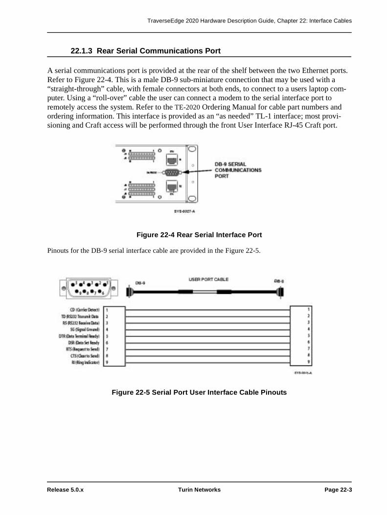
TraverseEdge 2020 Hardware Description Guide, Chapter 22: Interface Cables
Release 5.0.x Turin Networks Page 22-3
22.1.3 Rear Serial Communications Port
A serial communications port is provided at the rear of the shelf between the two Ethernet ports. Refer to Figure 22-4. This is a male DB-9 sub-miniature connection that may be used with a “straight-through” cable, with female connectors at both ends, to connect to a users laptop com-puter. Using a “roll-over” cable the user can connect a modem to the serial interface port to remotely access the system. Refer to the TE-2020 Ordering Manual for cable part numbers and ordering information. This interface is provided as an “as needed” TL-1 interface; most provi-sioning and Craft access will be performed through the front User Interface RJ-45 Craft port.
Figure 22-4 Rear Serial Interface Port
Pinouts for the DB-9 serial interface cable are provided in the Figure 22-5.
Figure 22-5 Serial Port User Interface Cable Pinouts

TraverseEdge 2020 Hardware Description Guide, Chapter 22: Interface Cables
Page 22-4 Turin Networks Release 5.0.x
22.2 DS1 Interface CablesWhen equipped with an ETS2 shelf, the TE-2020 can be equipped with DS1 PLMs capable of terminating a total of 168 DS1s per shelf. At the rear of the ETS2 shelf are twelve 64-pin female Champ connectors uti-lized for these DS1 interfaces. Refer to Figure 22-6.
Figure 22-6 ETS2 Backplane - Interface Connectors
The DS1 interface cables use a 64-pin male Champ connector with a shielded hood and a #4-40 screw to hold the connector to the chassis. Refer to Figure 22-7. Turin Networks has terminated (Figure 22-7) and unterminated (Figure 22-8) DS1 cables available for purchase. Refer to the TE-2020 Ordering Manual for details (WR-D2020-ORD-040000).
Figure 22-7 Terminated DS1 Cable with Male Connectors

TraverseEdge 2020 Hardware Description Guide, Chapter 22: Interface Cables
Release 5.0.x Turin Networks Page 22-5
Figure 22-8 Unterminated DS1 Cable
Table 22-1 lists port pin out information for the DS1 connectors and the terminated cable (P1 and P2 are either end of the cable as shown in Figure 22-7).
Table 22-1 DS1 Connector Terminations
22.3 DS3 Interface CablesWhen equipped with an ETS1 or ETS2 shelf, the TE-2020 can be addtionally be equipped with DS3

TraverseEdge 2020 Hardware Description Guide, Chapter 22: Interface Cables
Page 22-6 Turin Networks Release 5.0.x
PLMs capable of terminating either 48 DS3s per ETS1, or 12 DS3s per ETS2. At the rear of the ETS2 shelf are 24 BNC connectors utilized for two DS3 PLMs (12 ports only in a 1:1 working/protect group). Ports 1 through 6 TX and RX are on the left rear side of the shelf while ports 7 through 12 TX and RX connectors are on the right rear side of the shelf. Refer to Figure 22-9.
.
Figure 22-9 ETS1 Backplane DS3 BNC Connections
At the rear of the ETS1 shelf are 96 BNC connectors utilized for up to 4 working DS3 PLMs and one pro-tect (1:4 protect group). Ports 1-12 are in Row 3, ports 13-24 in Row 4, ports 25-36 in Row 5, and ports 37-48 in Row 6. Each row has 24 connectors for 12 ports with TX/RX as shown in Figure 22-10.
Figure 22-10 ETS1 Backplane DS3 BNC Connections
Turin Networks has DS3 cables available for purchase in 12 or 24 port bundles. These are BNC to BNC 735 Coax Cable w/ 12 or 24 conductors, 1 meter long. Refer to the TE-2020 Ordering Manual for details (WR-D2020-ORD-040000).

TraverseEdge 2020 Hardware Description Guide, Chapter 22: Interface Cables
Release 5.0.x Turin Networks Page 22-7
22.4 FastE Patch Panel Interconnect CableFastE connections are provided in the form of 50-pin mini-Champ connectors in the center rear of the shelf. Refer to Figure 22-11.
Figure 22-11 FastE Backplane Connections
Turin Networks has terminated FastE cables available for purchase. Refer to the TE-2020 Ordering Man-ual for details (WR-D2020-ORD-040000). Table 22-2 lists port pin out information for the FastE connec-tors and the terminated cable (P1 and P2 are the ends of the terminated cable as indicated in Figure 22-12).
Figure 22-12 FastE Interface Cable with 50-pin Champ Connectors
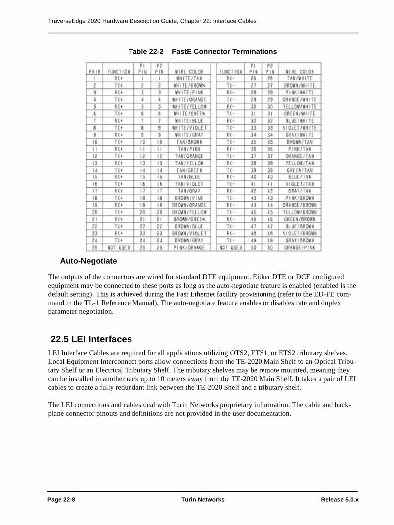
TraverseEdge 2020 Hardware Description Guide, Chapter 22: Interface Cables
Page 22-8 Turin Networks Release 5.0.x
Table 22-2 FastE Connector Terminations
Auto-Negotiate
The outputs of the connectors are wired for standard DTE equipment. Either DTE or DCE configured equipment may be connected to these ports as long as the auto-negotiate feature is enabled (enabled is the default setting). This is achieved during the Fast Ethernet facility provisioning (refer to the ED-FE com-mand in the TL-1 Reference Manual). The auto-negotiate feature enables or disables rate and duplex parameter negotiation.
22.5 LEI InterfacesLEI Interface Cables are required for all applications utilizing OTS2, ETS1, or ETS2 tributary shelves. Local Equipment Interconnect ports allow connections from the TE-2020 Main Shelf to an Optical Tribu-tary Shelf or an Electrical Tributary Shelf. The tributary shelves may be remote mounted, meaning they can be installed in another rack up to 10 meters away from the TE-2020 Main Shelf. It takes a pair of LEI cables to create a fully redundant link between the TE-2020 Shelf and a tributary shelf.
The LEI connections and cables deal with Turin Networks proprietary information. The cable and back-plane connector pinouts and definitions are not provided in the user documentation.

TraverseEdge 2020 Hardware Description Guide, Chapter 22: Interface Cables
Release 5.0.x Turin Networks Page 22-9
Figure 22-13 LEI Cable Pair

TraverseEdge 2020 Hardware Description Guide, Chapter 22: Interface Cables
Page 22-10 Turin Networks Release 5.0.x


Visit our website at:www.turinnetworks.com
Release 5.0.x
TraverseEdge 2020 System Documentation
800-0017-50