travelling wave fault location in hv...
TRANSCRIPT
5
Abstract
The article compares wave and impedance meth-ods used for determining fault location in high voltage lines, and presents the basic issues related to the exami-
nation of wave phenomena, describes the wave measure-ment methods and particular elements included in the measurement systems of wave locators.
TRAVELLING WAVE FAULT LOCATION IN HV LINES
Krzysztof Glik / Warsaw University of TechnologyRyszard Kowalik / Warsaw University of Technology
Désiré Dauphin Rasolomampionona / Warsaw University of Technology
1. INTRODUCTION
Determination of fault location in high-voltage lines is one of the most important issues which the protec-tion services have to deal with.
Determination of fault location may be used for the proper operation of protection equipment or for inspection and repair purposes. In the first case, it is very important to find the fault location quickly, whereas the accuracy may be limited only to determining the area of protection operation. Determining the location for inspection and repair purposes must have a high degree of accuracy. It is carried out through the fault location function implemented in a protection device, interference recorder or by a separate locator.
Accurate determination of the fault location for inspection and repair purposes enables:• faster restoration of the line to operation• preventing permanent faults• verification of protection operation.Faster restoration of the line to operation is a result of more efficient work of energy services, who, hav-
ing accurate information about the distance to the fault location, may quickly locate it even in mountainous or forested areas.
Most of the faults occurring in high-voltage lines are transient faults. Precise determination of the loca-tion of these faults enables carrying out preventive works (e.g. replacement of insulators, trimming of trees) in order to prevent permanent faults.
The use of information on the designated distance to verify the protection operation is based on confirm-ing that the protection is operational in the relevant zone, in a designated location in the case of fault simula-tion.
2. COMPARISON OF IMPEDANCE AND WAVE DETERMINATION OF FAULT LOCATION
Among the used locators two are of the greatest importance: impedance and wave locators. Impedance locators may be a part of a protection device, interference recorder, or constitute a separate device, similar to wave locators.
Operation of impedance locators is based on the measurement of current and voltage during fault. Due to the use of these two electrical values in determining the fault location, we deal with a measurement that is characterised by errors resulting from multiple factors, such as:
• transient components in current• current distortions caused by core saturation in current transformers• pre-charge current in the line immediately before the occurrence of a fault• transition resistance at the fault location• capacitance to earth of the line• magnetic coupling between the channels in dual lines
Travelling Wave Fault Location in Hv Lines
6
• inaccuracies in the data concerning the line impedance, particularly inaccurate determination of the zero line impedance due to the change in ground resistance along the line
• the phenomenon of current flow at the connection point of a tapped line in branched lines.Thanks to many years of operation of impedance-based fault locators, there are methods that reduce or
eliminate the effect of particular factors on the accuracy of measurement. Nevertheless, the accuracy of de-termination of fault location using impedance locators is in the range of 1-20 percent. The lower limit of error refers to metallic faults, determined at both ends of the line, while the upper limit occurs in the case of long lines, usually series-compensated. Error in determining fault location using the function in Siemens protection 7SA522 is declared for certain conditions at 2.5 percent of the line length. Such an accuracy is insufficient, giventhat transmission lines often have a length of hundreds of kilometres in environmentally diverse areas. Locating the particular damage by the operating staff in such conditions may result in too long a break in the transmis-sion of electricity.
Wave fault locators measure time instead of measuring current and voltage. This way, the effect of many of the above-mentioned factors on the measurement error is eliminated.
However, wave fault locators also have their drawbacks. The main factors that affect the error in determin-ing the distance to a fault location in such locators are the following:
• small fault angles• faults close to locator installation points• device synchronization error• ill-defined wave propagation velocity in the line• travelling wave detection error.The term “small fault angles” refers to a situation in which a fault occurs when the instantaneous voltage
value is close to zero, which prevents fault detection due to the low value of amplitude of the formed electro-magnetic wave. A sudden change in voltage is required for voltage and current wave with a high amplitude to appear in a high-voltage line, which in this case is not possible. This issue can be eliminated by a simultaneous determination of the fault location using a wave and impedance locator, with the latter responsible for locating the fault occurring at a small angle.
The error associated with a fault close to the locator installation point, which causes multiple wave reflec-tions between the locator installation point and fault location, may be eliminated by applying a sufficiently highsampling frequency.
Device synchronization error occurs for fault location determination using measurements on the two ends (type D location). This error is typically ±1 μs, which is associated with uncertainty in determining the distances of ±150 m for a single locator.
Wave propagation velocity in line is one of the values used to calculate the distance to the location. It depends on the line parameters and the path of electromagnetic wave – conductors (no-ground fault) or conductors and ground (ground fault).
Travelling wave detection error is associated with the reduction of amplitude and lengthening of the wave moving in the line. If a fault occurs closer to station A than station B, then due to the greater extension of the wave front reaching station B, detection of the wave in this station occurs later, causing additional error.
Wave locators are characterized by accurate determination of fault location in the range of 150-500 m, re-gardless of the line length. Such an accuracy applies also to long lines that are series-compensated, multicircuit lines with cable sections, and direct current lines.
High accuracy in determining the distance to the fault location and increase in network reliability, as well as cost savings resulting from the use of wave fault locators, made them widely used in such countries as the U.S., China, South Africa, Scotland and Canada. The national power system uses LAS-type wave locators, pro-duced by the Institute of Power Systems Automation Ltd, a Wroclaw-based Company, and TWS-type locator produced by Qualitrol.
The basic issues associated with the operation of wave fault locators are described below.
Krzysztof Glik, Ryszard Kowalik / Warsaw University of TechnologyDésiré Dauphin Rasolomampionona / Warsaw University of Technology
7
3. WAVE PHENOMENA
Of all the transient states that occur in the power system, wave phenomena in HV lines are characterized by the shortest duration, ranging from microseconds to milliseconds.
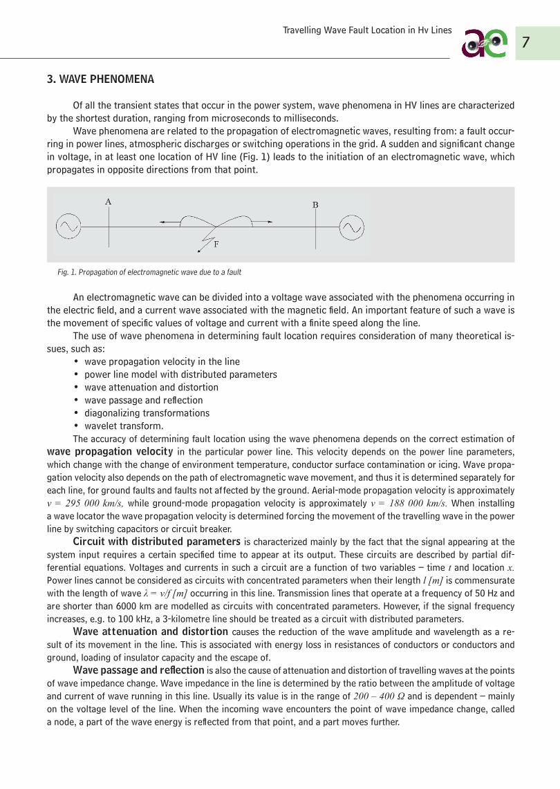
Wave phenomena are related to the propagation of electromagnetic waves, resulting from: a fault occur-ring in power lines, atmospheric discharges or switching operations in the grid. A sudden and significant change in voltage, in at least one location of HV line (Fig. 1) leads to the initiation of an electromagnetic wave, which propagates in opposite directions from that point.
Fig. 1. Propagation of electromagnetic wave due to a fault
An electromagnetic wave can be divided into a voltage wave associated with the phenomena occurring in the electric field, and a current wave associated with the magnetic field. An important feature of such a wave is the movement of specific values of voltage and current with a finite speed along the line.
The use of wave phenomena in determining fault location requires consideration of many theoretical is-sues, such as:
• wave propagation velocity in the line• power line model with distributed parameters• wave attenuation and distortion• wave passage and reflection• diagonalizing transformations• wavelet transform.The accuracy of determining fault location using the wave phenomena depends on the correct estimation of
wave propagation velocity in the particular power line. This velocity depends on the power line parameters, which change with the change of environment temperature, conductor surface contamination or icing. Wave propa-gation velocity also depends on the path of electromagnetic wave movement, and thus it is determined separately for each line, for ground faults and faults not affected by the ground. Aerial-mode propagation velocity is approximately v = 295 000 km/s, while ground-mode propagation velocity is approximately v = 188 000 km/s. When installing a wave locator the wave propagation velocity is determined forcing the movement of the travelling wave in the power line by switching capacitors or circuit breaker.
Circuit with distributed parameters is characterized mainly by the fact that the signal appearing at the system input requires a certain specified time to appear at its output. These circuits are described by partial dif-ferential equations. Voltages and currents in such a circuit are a function of two variables – time t and location x. Power lines cannot be considered as circuits with concentrated parameters when their length l [m] is commensurate with the length of wave λ = v/f [m] occurring in this line. Transmission lines that operate at a frequency of 50 Hz and are shorter than 6000 km are modelled as circuits with concentrated parameters. However, if the signal frequency increases, e.g. to 100 kHz, a 3-kilometre line should be treated as a circuit with distributed parameters.
Wave attenuation and distortion causes the reduction of the wave amplitude and wavelength as a re-sult of its movement in the line. This is associated with energy loss in resistances of conductors or conductors and ground, loading of insulator capacity and the escape of.
Wave passage and reflection is also the cause of attenuation and distortion of travelling waves at the points of wave impedance change. Wave impedance in the line is determined by the ratio between the amplitude of voltage and current of wave running in this line. Usually its value is in the range of 200 – 400 Ω and is dependent – mainly on the voltage level of the line. When the incoming wave encounters the point of wave impedance change, called a node, a part of the wave energy is reflected from that point, and a part moves further.
Travelling Wave Fault Location in Hv Lines
8
Diagonalizing transformations are used in order to consider three-phase lines as three separate single-phase lines without mutual magnetic couplings. Theoretically, there is an infinite number of diagonalizing transforma-tions, the most common of which is the symmetrical components method. However, in the case of wave phenomenon analysis, such a transformation is not used, which results from the nature of wave phenomena described by instan-taneous values of voltages and currents, which cannot be converted to compatible, negative and zero component. Transformation matrices that consist of elements which are not complex numbers (as in the case of the transforma-tion of symmetrical components) are used.
Wavelet transform is used to analyse non-stationary signals, i.e. signals whose statistical characteristics (mean value, mean square value, correlation function) are time functions (they depend on the choice of baseline). One of the most important features of wavelet transform is the ability to determine the time at which a high fre-quency signal occurred, at the same time examining the components of a low frequency signal.
4. MEASUREMENT METHODS
Depending on the measuring method used, wave fault locators are divided into five types: A, B, C, D and E. The operation of each type of locator is based on an analysis of the incoming electromagnetic wave caused by the fault. The types of locators are described below.
A-type locatorsA-type locators perform measurements on one side of the line. The distance to the fault location is calcu-
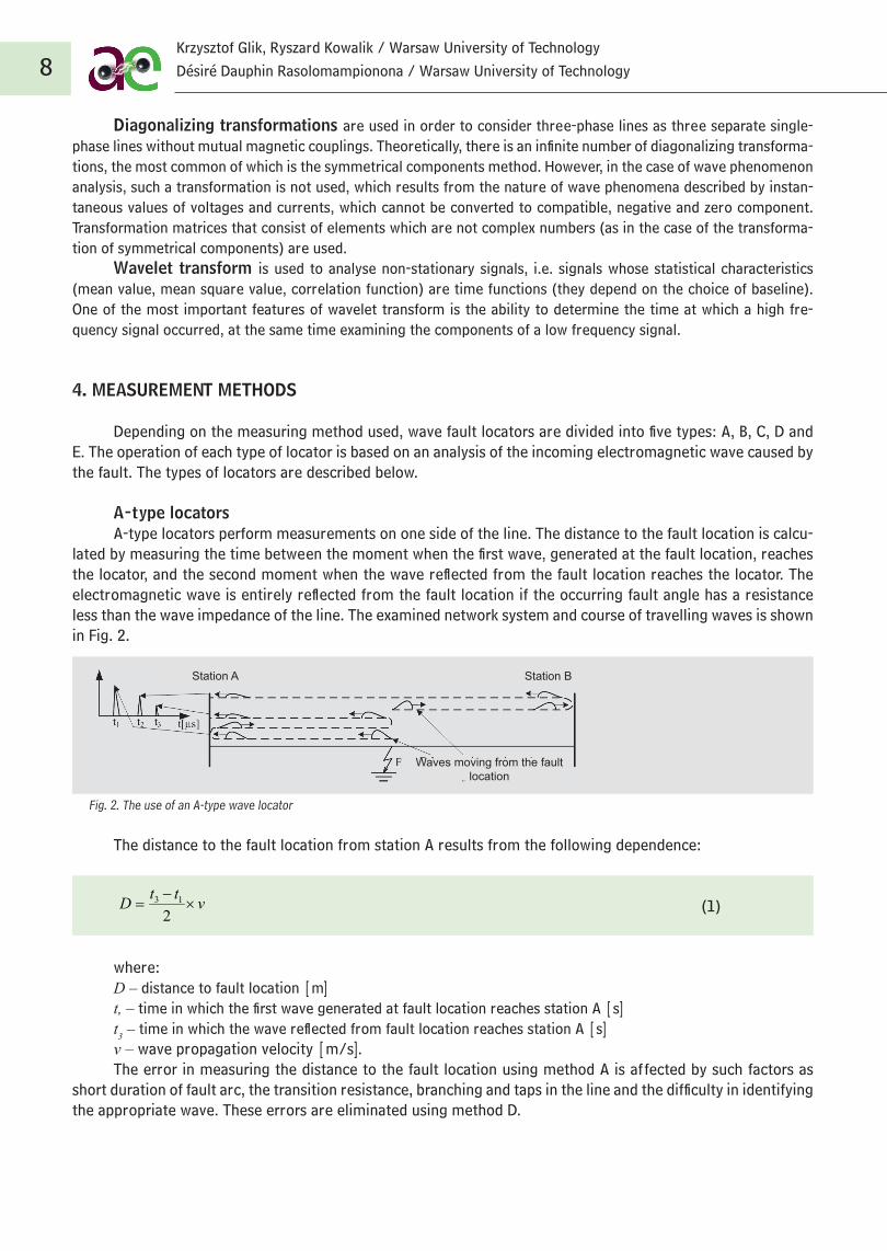
lated by measuring the time between the moment when the first wave, generated at the fault location, reaches the locator, and the second moment when the wave reflected from the fault location reaches the locator. The electromagnetic wave is entirely reflected from the fault location if the occurring fault angle has a resistance less than the wave impedance of the line. The examined network system and course of travelling waves is shown in Fig. 2.
Fig. 2. The use of an A-type wave locator
The distance to the fault location from station A results from the following dependence:
(1)
where:D – distance to fault location [m]t, – time in which the first wave generated at fault location reaches station A [s]t3 – time in which the wave reflected from fault location reaches station A [s]v – wave propagation velocity [m/s].The error in measuring the distance to the fault location using method A is affected by such factors as
short duration of fault arc, the transition resistance, branching and taps in the line and the difficulty in identifying the appropriate wave. These errors are eliminated using method D.
vttD
213
Waves moving from the fault location
Station BStation A
Krzysztof Glik, Ryszard Kowalik / Warsaw University of TechnologyDésiré Dauphin Rasolomampionona / Warsaw University of Technology
9
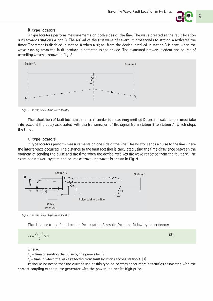
B-type locatorsB-type locators perform measurements on both sides of the line. The wave created at the fault location
runs towards stations A and B. The arrival of the first wave of several microseconds to station A activates the timer. The timer is disabled in station A when a signal from the device installed in station B is sent, when the wave running from the fault location is detected in the device. The examined network system and course of travelling waves is shown in Fig. 3.
Fig. 3. The use of a B-type wave locator
The calculation of fault location distance is similar to measuring method D, and the calculations must take into account the delay associated with the transmission of the signal from station B to station A, which stops the timer.
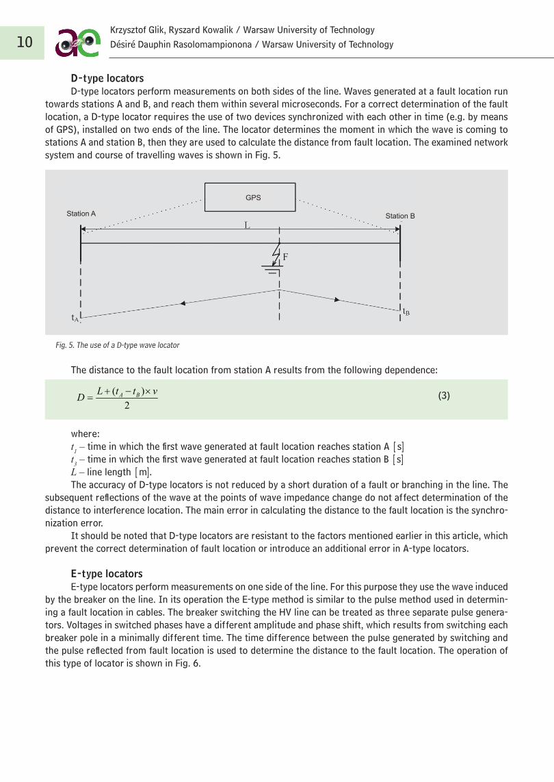
C -type locatorsC -type locators perform measurements on one side of the line. The locator sends a pulse to the line where
the interference occurred. The distance to the fault location is calculated using the time difference between the moment of sending the pulse and the time when the device receives the wave reflected from the fault arc. The examined network system and course of travelling waves is shown in Fig. 4.
Fig. 4. The use of a C -type wave locator
The distance to the fault location from station A results from the following dependence:
(2)
where:t 1 – time of sending the pulse by the generator [s]t2 – time in which the wave reflected from fault location reaches station A [s]It should be noted that the current use of this type of locators encounters difficulties associated with the
correct coupling of the pulse generator with the power line and its high price.
vttD
212
Station A Station B
Station A Station B
Pulse generator
Pulse sent to the line
Travelling Wave Fault Location in Hv Lines
10
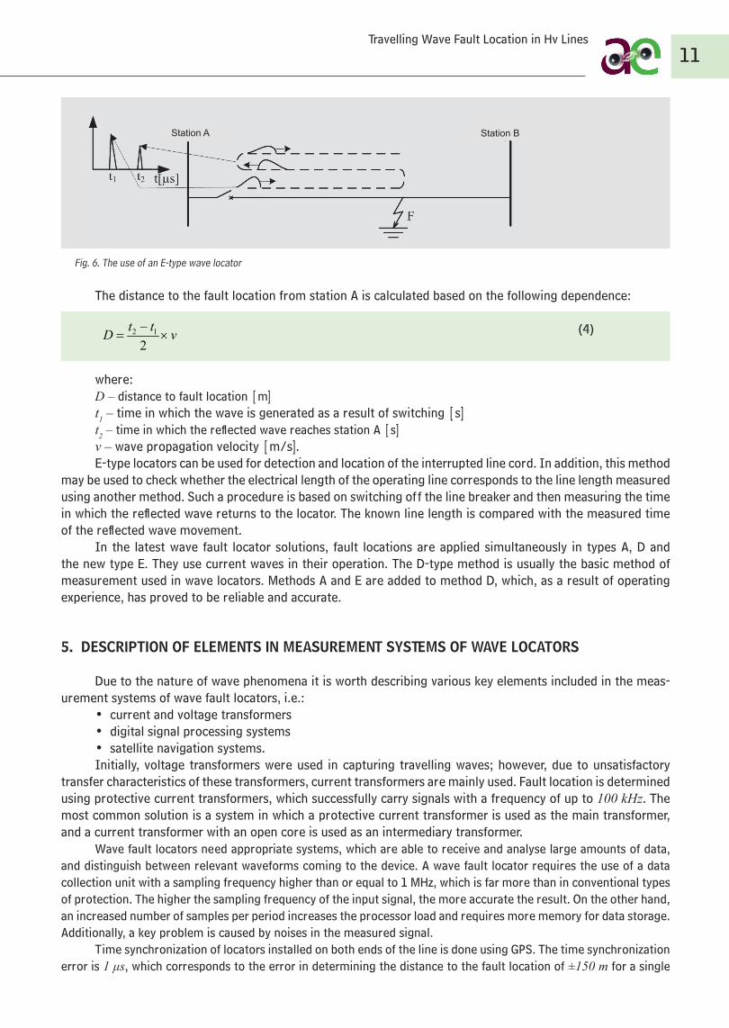
D-type locatorsD-type locators perform measurements on both sides of the line. Waves generated at a fault location run
towards stations A and B, and reach them within several microseconds. For a correct determination of the fault location, a D-type locator requires the use of two devices synchronized with each other in time (e.g. by means of GPS), installed on two ends of the line. The locator determines the moment in which the wave is coming to stations A and station B, then they are used to calculate the distance from fault location. The examined network system and course of travelling waves is shown in Fig. 5.
Fig. 5. The use of a D-type wave locator
The distance to the fault location from station A results from the following dependence:
(3)
where:t1 – time in which the first wave generated at fault location reaches station A [s]t3 – time in which the first wave generated at fault location reaches station B [s]L – line length [m].The accuracy of D-type locators is not reduced by a short duration of a fault or branching in the line. The
subsequent reflections of the wave at the points of wave impedance change do not affect determination of the distance to interference location. The main error in calculating the distance to the fault location is the synchro-nization error.
It should be noted that D-type locators are resistant to the factors mentioned earlier in this article, which prevent the correct determination of fault location or introduce an additional error in A-type locators.
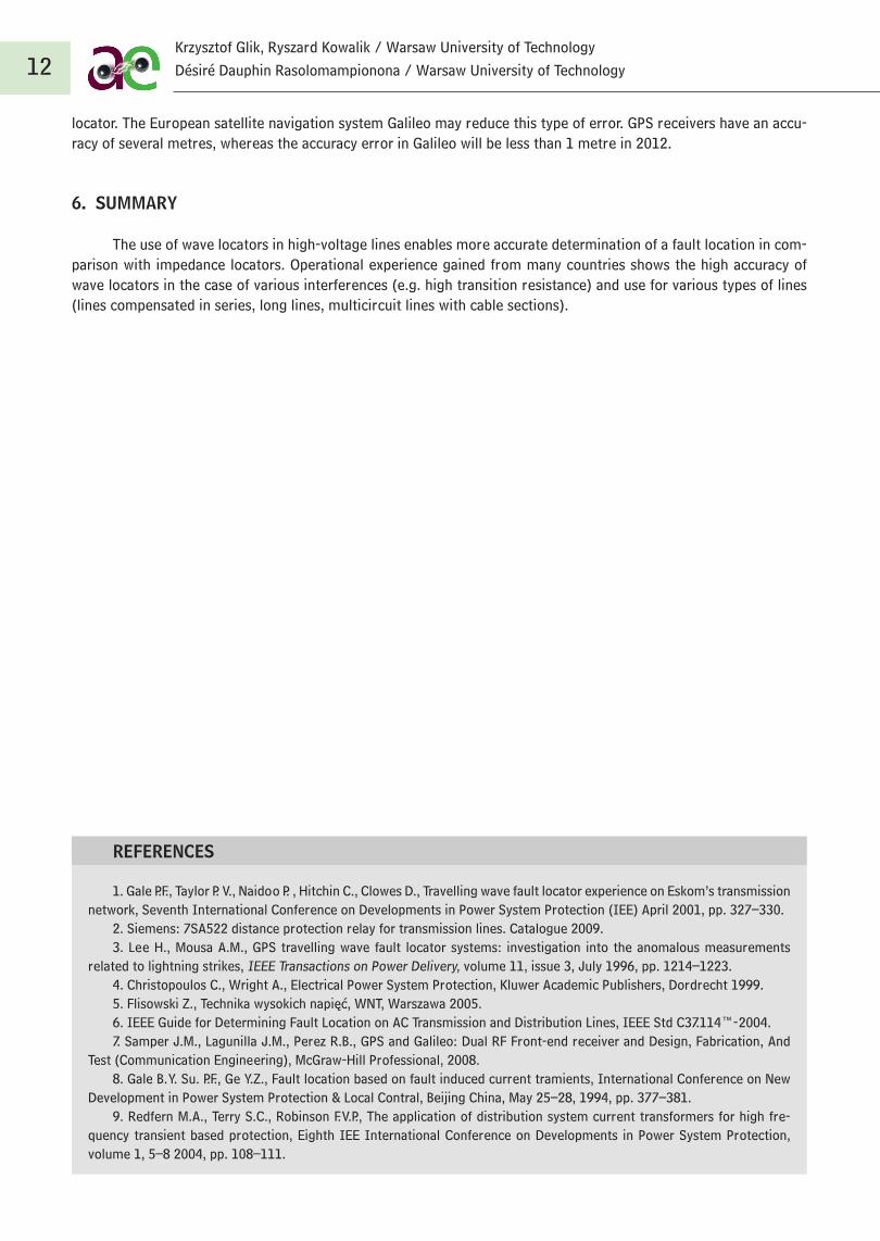
E-type locatorsE-type locators perform measurements on one side of the line. For this purpose they use the wave induced
by the breaker on the line. In its operation the E-type method is similar to the pulse method used in determin-ing a fault location in cables. The breaker switching the HV line can be treated as three separate pulse genera-tors. Voltages in switched phases have a different amplitude and phase shift, which results from switching each breaker pole in a minimally different time. The time difference between the pulse generated by switching and the pulse reflected from fault location is used to determine the distance to the fault location. The operation of this type of locator is shown in Fig. 6.
2
)( vttLD BA
Station A Station B
GPS
Krzysztof Glik, Ryszard Kowalik / Warsaw University of TechnologyDésiré Dauphin Rasolomampionona / Warsaw University of Technology
11
Fig. 6. The use of an E-type wave locator
The distance to the fault location from station A is calculated based on the following dependence:
(4)
where:D – distance to fault location [m]t1 – time in which the wave is generated as a result of switching [s]t2 – time in which the reflected wave reaches station A [s]v – wave propagation velocity [m/s].E-type locators can be used for detection and location of the interrupted line cord. In addition, this method
may be used to check whether the electrical length of the operating line corresponds to the line length measured using another method. Such a procedure is based on switching off the line breaker and then measuring the time in which the reflected wave returns to the locator. The known line length is compared with the measured time of the reflected wave movement.
In the latest wave fault locator solutions, fault locations are applied simultaneously in types A, D and the new type E. They use current waves in their operation. The D-type method is usually the basic method of measurement used in wave locators. Methods A and E are added to method D, which, as a result of operating experience, has proved to be reliable and accurate.
5. DESCRIPTION OF ELEMENTS IN MEASUREMENT SYSTEMS OF WAVE LOCATORS
Due to the nature of wave phenomena it is worth describing various key elements included in the meas-urement systems of wave fault locators, i.e.:
• current and voltage transformers• digital signal processing systems• satellite navigation systems.Initially, voltage transformers were used in capturing travelling waves; however, due to unsatisfactory
transfer characteristics of these transformers, current transformers are mainly used. Fault location is determined using protective current transformers, which successfully carry signals with a frequency of up to 100 kHz. The most common solution is a system in which a protective current transformer is used as the main transformer, and a current transformer with an open core is used as an intermediary transformer.
Wave fault locators need appropriate systems, which are able to receive and analyse large amounts of data, and distinguish between relevant waveforms coming to the device. A wave fault locator requires the use of a data collection unit with a sampling frequency higher than or equal to 1 MHz, which is far more than in conventional types of protection. The higher the sampling frequency of the input signal, the more accurate the result. On the other hand, an increased number of samples per period increases the processor load and requires more memory for data storage. Additionally, a key problem is caused by noises in the measured signal.
Time synchronization of locators installed on both ends of the line is done using GPS. The time synchronization error is 1 μs, which corresponds to the error in determining the distance to the fault location of ±150 m for a single
vttD
212
Station A Station B
Travelling Wave Fault Location in Hv Lines
12
REFERENCES
locator. The European satellite navigation system Galileo may reduce this type of error. GPS receivers have an accu-racy of several metres, whereas the accuracy error in Galileo will be less than 1 metre in 2012.
6. SUMMARY
The use of wave locators in high-voltage lines enables more accurate determination of a fault location in com-parison with impedance locators. Operational experience gained from many countries shows the high accuracy of wave locators in the case of various interferences (e.g. high transition resistance) and use for various types of lines (lines compensated in series, long lines, multicircuit lines with cable sections).
1. Gale P.F., Taylor P. V., Naidoo P. , Hitchin C., Clowes D., Travelling wave fault locator experience on Eskom’s transmission network, Seventh International Conference on Developments in Power System Protection (IEE) April 2001, pp. 327–330.
2. Siemens: 7SA522 distance protection relay for transmission lines. Catalogue 2009.3. Lee H., Mousa A.M., GPS travelling wave fault locator systems: investigation into the anomalous measurements
related to lightning strikes, IEEE Transactions on Power Delivery, volume 11, issue 3, July 1996, pp. 1214–1223.4. Christopoulos C., Wright A., Electrical Power System Protection, Kluwer Academic Publishers, Dordrecht 1999.5. Flisowski Z., Technika wysokich napięć, WNT, Warszawa 2005.6. IEEE Guide for Determining Fault Location on AC Transmission and Distribution Lines, IEEE Std C37.114™- 2004.7. Samper J.M., Lagunilla J.M., Perez R.B., GPS and Galileo: Dual RF Front-end receiver and Design, Fabrication, And
Test (Communication Engineering), McGraw-Hill Professional, 2008.8. Gale B. Y. Su. P.F., Ge Y.Z., Fault location based on fault induced current tramients, International Conference on New
Development in Power System Protection & Local Contral, Beijing China, May 25–28, 1994, pp. 377–381.9. Redfern M.A., Terry S.C., Robinson F. V.P., The application of distribution system current transformers for high fre-
quency transient based protection, Eighth IEE International Conference on Developments in Power System Protection, volume 1, 5–8 2004, pp. 108–111.
Krzysztof Glik, Ryszard Kowalik / Warsaw University of TechnologyDésiré Dauphin Rasolomampionona / Warsaw University of Technology