trauma hal - s3.amazonaws.com · trauma hal® s3040.100 gaumard® simulators for health care...
TRANSCRIPT

User Guide 14.9.3© Gaumard Scientiic Company, 2014
All Rights Reserved
www.Gaumard.com
Trauma HAL® S3040.100
®
GaumardSimulators for Health Care Education
Trauma HAL® is an interactive educational system developed to assist a certiied instructor. It is not a substitute for a comprehensive understanding of the subject matter and not intended for clinical decision making.

2 | User Guide | Combat HAL® |

| Combat HAL® | User Guide | 3
End User License Agreement
Care and Cautions
Overall Warnings .................................................................................................. 9
General ................................................................................................................................ 9
Set Up.................................................................................................................................. 9
Operating Conditions ........................................................................................................... 9
Storage ................................................................................................................................ 9
Procedures .......................................................................................................................... 9
Cleaning .............................................................................................................................. 9
IV Arm And Needle Decompression .................................................................................. 10Electrical Therapy .............................................................................................................. 10
Getting Started
Overview.............................................................................................................. 12
Airway & Appearance ........................................................................................................ 12Breathing ........................................................................................................................... 12Circulation.......................................................................................................................... 12Speech .............................................................................................................................. 12Cephalic............................................................................................................................. 12Trauma .............................................................................................................................. 13Systemic ............................................................................................................................ 13User Interface .................................................................................................................... 13Vital Signs Monitor (Optional) ............................................................................................ 13Other.................................................................................................................................. 13Speciications .................................................................................................................... 13
Equipment Set Up
Trauma HAL Setup ............................................................................................. 15
Simulator Placement ......................................................................................................... 15Leg Assembly .................................................................................................................... 15Battery ............................................................................................................................... 15
Control Tablet PC ............................................................................................... 16
Using The Stylus ............................................................................................................... 16Wireless Communication USB Module.............................................................................. 16Streaming Audio Headset .................................................................................................. 17
Virtual Monitor (Optional) ................................................................................ 17
Gaumard Monitors ............................................................................................................. 18
Working with Trauma HAL®
Airway .................................................................................................................. 20
Nasal and oral Intubation................................................................................................... 20Airway Complications ........................................................................................................ 20Right Mainstem Intubation ................................................................................................. 21

4 | User Guide | Combat HAL® |
Airway Sounds................................................................................................................... 21Surgical Airway .................................................................................................................. 21
Breathing ............................................................................................................. 23
Bilateral Chest Rise ........................................................................................................... 23Pulmonary Ventilation ........................................................................................................ 23Breathing Patterns ............................................................................................................. 23Needle Decompression ..................................................................................................... 24Hemothorax Sites .............................................................................................................. 24REAL CO2 EXHALATION (Optional)................................................................................. 24
Cardiac ................................................................................................................ 26
Heart Sounds..................................................................................................................... 26ECG Monitoring and Electrical Therapy ............................................................................ 26Chest Compressions ......................................................................................................... 27
Circulation ........................................................................................................... 27
Bilateral Pulses .................................................................................................................. 27Programmable Blood Pressure ......................................................................................... 28Bilateral IV arms ................................................................................................................ 28Oxygen Saturation ............................................................................................................. 30
Cephalic............................................................................................................... 31
Central Cyanosis ............................................................................................................... 31Active Eyes ........................................................................................................................ 31Seizures............................................................................................................................. 31
Systemic .............................................................................................................. 32
Intramuscular injection sites .............................................................................................. 32Bowel Sounds.................................................................................................................... 32Gastric Distension ............................................................................................................. 32Sternal Io Access ............................................................................................................... 32Intraosseous Access At Tibia ............................................................................................. 33
Streaming Audio ................................................................................................................ 34
Trauma ................................................................................................................. 35
Programmable Ear, Eye, And Mouth Fluid Secretions ...................................................... 35Fluid Reservoir .................................................................................................................. 35Wound Sites ...................................................................................................................... 37Trauma Arm ....................................................................................................................... 38Trauma leg ........................................................................................................................ 39
Urinary Catheterization ...................................................................................................... 40Interchangeable Male Genitalia ......................................................................................... 40
Other .................................................................................................................... 40
Vital Signs Monitor (Optional) ............................................................................................ 40Pro+ (Optional) .................................................................................................................. 41Wound Kits (optional) ........................................................................................................ 41

| Combat HAL® | User Guide | 5
Working with UNI™
Initializing the Simulator .................................................................................... 43
Proiles And Operating Modes ........................................................................................... 43Manual Mode ..................................................................................................................... 43Automatic Mode................................................................................................................. 44Managing Proiles .............................................................................................................. 44
UNI Interface ....................................................................................................... 45
Connection Status ............................................................................................................. 46Session Clock .................................................................................................................... 46Power/Stand-By Button ..................................................................................................... 46Fluid Reservoir .................................................................................................................. 46Status/Details Controls ...................................................................................................... 47
Appendix
More about Scenarios ........................................................................................ 52
Thinking In Terms Of Palette Items ................................................................................... 52Smart Scenarios ................................................................................................................ 52Factory Preset Scenarios Description ............................................................................... 53
Troubleshooting ................................................................................................. 55
General Troubleshooting Guide......................................................................................... 55
Pro+ System Ofline Updater (If Applicable) .................................................... 58
Wireless Ad-Hoc Network .................................................................................. 63
UNI Network Coniguration ................................................................................................ 63Gaumard Monitors Network Coniguration ........................................................................ 63Conigure The Vital Signs Broadcast ................................................................................. 64
Microphone Boost for Streaming Audio .......................................................... 65
Replacing Common Consumables ................................................................... 65
Gather the following items: ................................................................................................ 65Replacing the IV veins ....................................................................................................... 65
Warranty .............................................................................................................. 68
Exclusive One-Year Limited Warranty ............................................................................... 68

6 | User Guide | End User License Agreement |
End User License
Agreement
This is a legal agreement between you, the end user, and Gaumard® Scientiic Company, Inc. (“Gaumard”). This software is protected by copyright laws and remains the sole property of Gaumard. By installing the UNI (the "Software") media, you agree to be bound by the terms of this agreement. If you do not agree to the terms of this agreement, promptly return the uninstalled media and accompanying items to Gaumard at the address indicated below.
1. Grant of License. Gaumard hereby grants to you (an individual or institution) the right to install and activate the Software on one computer for use with one Interactive patient simulator system. The software may also be installed on any number of other computers at the same institution so that students may access the learning resources. One copy of the software may be made for backup purposes. You may not network this Software, or allow multiple users unless you purchased a multi-user workstation license. Sharing this Software with other individuals or allowing other individuals to view the contents of this Software is in violation of this license.
2. Copyright. The Software is owned by Gaumard and protected by United States copyright laws and international treaty provisions. Therefore, you must treat this Software like any other copyrighted material. You may not make this Software or copies thereof available in any manner or form or use, copy or transfer the Software, in whole or in part, except as provided herein.
3. Other Restrictions. You may not rent or lease this Software to any other party. You may not alter, merge, modify, adapt, reverse engineer, decompile or disassemble the software, or disclose the contents of this Software to any other party.
4. Electronic Transmission of Software. If you received the Software by electronic transmission or by Internet delivery, by installation of the Software, you acknowledge that you have read and understand this license agreement and agree to be bound by its terms and conditions.
5. Term of Agreement. The term of this Agreement and the license granted to you pursuant hereto shall commence upon installation of this Software. This Agreement and the license granted herein may otherwise be terminated by Gaumard in the event that you are in breach of any provision of this Agree¬ment. In the event of termination, you agree to immediately return this Software, accompanying items, and any copies thereof to Gaumard.
6. LIMITED WARRANTY
(A) THE CD-ROM MEDIA (THE "MEDIA") WHICH CONTAINS THIS SOFTWARE IS WARRANTED, FOR A PERIOD OF 30 DAYS FROM THE DATE OF PURCHASE, TO BE FREE FROM DEFECTS IN MATERIAL AND WORKMANSHIP. ELECTRONIC TRANSMISSION IS WARRANTED TO BE FREE FROM DEFECTS AT THE MOMENT OF TRANSMISSION. YOUR SOLE AND EXCLUSIVE REMEDY, AND GAUMARD'S SOLE LIABILITY, IS TO REPLACE THE DEFECTIVE MEDIA OR TO REPEAT THE ELECTRONIC TRANSMISSION PROVIDED THAT YOU NOTIFY GAUMARD IN WRITING OF SUCH DEFECT OR DEFECTIVE TRANSMISSION AND RETURN THE DEFECTIVE MEDIA, IF ANY, DURING THE 30-DAY WARRANTY PERIOD.
| End User License Agreement | User Guide | 7
(B) EXCEPT AND TO THE EXTENT EXPRESSLY PROVIDED IN PARAGRAPH (A), THE SOFTWARE AND ACCOMPANYING WRITTEN MATERIALS ARE PROVIDED ON AN "AS IS" BASIS, WITHOUT ANY WARRANTIES OF ANY KIND, INCLUDING, BUT NOT LIMITED TO, ANY IMPLIED WARRANTIES OF MERCHANTABILITY OR FITNESS FOR ANY PARTICULAR PURPOSE. NO ORAL OR WRITTEN INFORMATION OR ADVICE GIVEN BY GAUMARD, ITS DEALERS, DISTRIBUTORS, AGENTS OR EMPLOYEES SHALL CREATE A WARRANTY OR IN ANY WAY INCREASE THE SCOPE OF THIS WARRANTY, AND YOU MAY NOT RELY ON ANY SUCH INFORMATION OR ADVICE. GAUMARD DOES NOT WARRANT, GUARANTEE, OR MAKE ANY REPRESENTATIONS REGARDING THE USE OR THE RESULTS OF USE, OF THE SOFTWARE OR WRITTEN MATERIALS IN TERMS OF CORRECTNESS, ACCURACY, RELIABILITY, CURRENTNESS, OR OTHERWISE, AND THE ENTIRE RISK AS TO THE RESULTS AND PERFORMANCE OF THE SOFTWARE IS ASSUMED BY YOU. IF THE SOFTWARE OR WRITTEN MATERIALS ARE DEFECTIVE, YOU AND NOT GAUMARD OR ITS DEALERS, DISTRIBUTORS, AGENTS, OR EMPLOYEES, ASSUME THE ENTIRE COST OF ALL NECESSARY SERVICING, REPAIR OR CORRECTION OTHER THAN EXPRESSLY DESCRIBED ABOVE.
(C) NEITHER GAUMARD NOR ANYONE ELSE WHO HAS BEEN INVOLVED IN THE CREATION, PRODUCTION OR DELIVERY OF THIS PRODUCT SHALL BE LIABLE FOR ANY DIRECT, INDIRECT, CONSEQUENTIAL OR INCIDENTAL DAMAGES (INCLUDING DAMAGES FOR LOSS OF BUSINESS PROFITS, BUSINESS INTERRUPTION, LOSS OF BUSINESS INFORMATION, AND THE LIKE) ARISING OUT OF THE USE OR INABILITY TO USE SUCH PRODUCT OR RELATED TO THIS AGREEMENT EVEN IF GAUMARD HAS BEEN ADVISED OF THE POSSIBILITY OF SUCH DAMAGES. GAUMARD SHALL NOT BE LIABLE TO YOU FOR ANY INDIRECT, SPECIAL, INCIDENTAL, OR CONSEQUENTIAL DAMAGES OR LOST PROFITS ARISING OUT OF OR RELATED TO THIS AGREEMENT OR YOUR USE OF THE SOFTWARE AND/OR THE RELATED DOCUMENTATION, EVEN IF GAUMARD HAS BEEN ADVISED OF THE POSSIBILITY OF SUCH DAMAGES. IN NO EVENT SHALL GAUMARD'S LIABILITY HERE UNDER, IF ANY, EXCEED THE PURCHASE PRICE PAID BY YOU FOR THE SOFTWARE.
ALL RIGHTS NOT EXPRESSLY GRANTED IN THIS LICENSE AGREEMENT ARE RESERVED BY GAUMARD.
ACKNOWLEDGMENT
BY INSTALLATION OF THIS SOFTWARE, YOU ACKNOWLEDGE THAT YOU HAVE READ AND UNDERSTAND THE FOREGOING AND THAT YOU AGREE TO BE BOUND BY ITS TERMS AND CONDITIONS. YOU ALSO AGREE THAT THIS AGREEMENT IS THE COMPLETE AND EXCLUSIVE STATEMENT OF AGREEMENT BETWEEN THE PARTIES AND SUPERSEDES ALL PROPOSED OR PRIOR AGREEMENTS, ORAL OR WRITTEN, AND ANY OTHER COMMUNICATIONS BETWEEN THE PARTIES RELATING TO THE LICENSE DESCRIBED HEREIN.

8 | User Guide | Care and Cautions |
Care and Cautions

| Care and Cautions | User Guide | 9
Overall WarningsRemember that damage caused by misuse is not covered by your warranty. It is critical to understand and comply with the following guidelines:
GENERAL
• Ball point pens, ink and markers permanently stain the skin.
• Do not wrap this or any other Gaumard product in newsprint.
• Indelible marks made with ballpoint pens, ink or marker cannot be removed.
• Only use Gaumard’s provided simulated blood. Any other simulated blood containing sugar or any additive may cause blockage and/or interruption of the vasculature system.
WARNING
Vein tubing contains latex which may cause allergic reactions. Users allergic or sensitive to latex should avoid contact. Discontinue use of this product and seek medical attention if an allergic reaction occurs.
• Replacement parts are available from Gaumard Scientiic or from your Distributor.
SET UP
When connecting the battery to the simulator, make sure to match the two color-coded connectors to the corresponding color-coded battery terminals.
Do not use universal AC adapters. Only use the AC adapter supplied with the simulator.
NEVER disconnect the communications module while the UNI software is running. The software will halt, and the module may be damaged.
Do not remove the chest skin. Internal components are serviced by Gaumard certiied technicians only.
Never connect Trauma HAL to Ethernet cards, LAN networks or unauthorized diagnostic equipment. Doing so may cause damage to the system.
Do not connect the RJ45 cable directly to the tablet’s Ethernet port. Wired communication can only be established using the RF module wired port.
Turn Trauma HAL OFF before replacing the battery. Failure to do so could result in serious damage to the system.
OPERATING CONDITIONS
• Operating the simulator outside these ranges may affect performance:
• Operating temperature: 50°-95° F (10°-35° C)
• Humidity: 5%-95% (non-condensing)
STORAGE
Store Trauma HAL® in a cool, dry place. Extended storage above 85 degrees Fahrenheit (29 Celsius) will cause the simulator to soften and slowly warp. It is acceptable to operate the simulator at an ambient temperature of 95 degrees Fahrenheit (35 Celsius).
Do not store the simulator with a discharged battery. It is good practice to re-charge the battery at the end of every simulation session. In addition, make sure the battery is re-charged at least once every 2 months even if the simulator is not being used; otherwise permanent loss of capacity might occur because of self-discharge.
PROCEDURES
• Do not intubate without lubricating the airway adjunct with oil lubricant (provided). Failure to do so will make intubation very dificult and is likely to result in damage.
• Do not introduce lammable gases into the airway.
• Mouth to mouth resuscitation without a barrier device is not recommended, as it will contaminate the airway. Treat Trauma HAL® with the same precautions that would be used with a real patient.
• Do not turn Trauma HAL’s head sideways while laryngospasm is on. Doing so may damage the mechanism that closes the larynges.
• Always dispose of system batteries in compliance with local laws and regulations.
• Do not perform surgical exercises on the ventilation insert.
• Only replace trauma limbs when Trauma HAL is powered off or in standby mode.
CLEANING
• The simulator should be cleaned with a cloth dampened with diluted liquid dish washing soap. If medical adhesives remain on the skin, clean with alcohol wipes.

10 | User Guide | Care and Cautions |
• DO NOT USE “GOO GONE®” as the citric acid in the formula will cause pitting of the various materials comprising your simulator.
• Remove all traces of any lubricant.
• Do not clean with harsh abrasives.
• Do not use povidone iodine on the simulator.
• Dry thoroughly.
IV ARM AND NEEDLE DECOMPRESSION
• Only use Gaumard’s provided simulated blood. Any other simulated blood containing sugar or any additive may cause blockage and/or interruption of the vasculature system.
• The use of needles larger than 22 gauge will reduce the lifetime of the lower arms’ skin and veins.
• Do not inject luids into the intramuscular sites.
• Do not add liquids to the hemothorax sites. Doing so may damage the simulator and void the warranty.
• Maximum amount of luid injected without draining should not exceed 40 mL and the maximum injection rate is 9999 mL/hr.
• At the end of every simulation session, you must purge the IV system with alcohol 70% Failure to do so may cause blockage and/or interruption of the vasculature system
ELECTRICAL THERAPY
• Deibrillation is only allowed on the large sternum and apex sites, circled red below. NEVER deliver a shock to ECG electrode targets on the shoulders or waist, marked green below. Doing so will not create a ire hazard, nor is there risk of shock to the provider, but internal damage to the simulator may result. This situation is considered improper use and is NOT covered by the Trauma HAL warranty. The system will require repair at our facility.
• There are inherent dangers in the use of some medical devices. For simulations that incorporate electrical therapy of any kind, always know your equipment, and follow the device manufacturers’ safety guidelines.
ECG AND ELECTRICAL THERAPY CHECKLIST AND WARNINGS
• Only deliver electrical therapy when the simulator is fully assembled, dry, and undamaged.
• Make sure the deibrillation patches on the simulator are in good condition, including removing any and all gel residue on the deibrillation patches from previous use(s).
• It is a good practice to remove gel residues after every use. Failure to do so will leave behind a ilm of electrode gel that hardens causing arcing and pitting.
• Do not re-use the gel-adhesive pads. Do not leave them on for next day use.
• Use hard paddles or wet-gel pads preferably.
• Avoid using solid-gel pads since they present higher risk of burning the simulator’s skin.
• Gel pads have a shelf life. Make sure they are not expired to avoid arcing.
• Make sure the simulator is not in contact with any electrically conductive surfaces.
• Use the simulator only in a well-ventilated area, free of all lammable gases.
• NEVER attempt to service or modify any of the electrical connections, especially those between conductive skin sites and the internal electronics.
• Discontinue use if any wires are found exposed with damaged insulation.
• Real medical products, especially electrodes, sometimes use powerful adhesives that can be dificult to remove. A gentle, degreasing cleanser may be needed.
• Electrode gel on the skin between any two electrode targets can become a pathway for electrical current, just as in real life. If this occurs, the simulator’s skin can be burned.
• Do not allow deibrillation pads to overlap ECG sites. Doing so will may damage the simulator and cause arcing.
• Should dark traces appear on the conductive patches due to gel residue or previous arcing, use a pencil eraser to remove the traces and then clean with alcohol.
• DO NOT SCRATCH the conductive patches with abrasive objects; doing so will cause irreversible damage to the conductive sites and subsequently cause arcing.

| Getting Started | User Guide | 11
Getting Started

12 | User Guide | Getting Started |
OverviewPlease reference the simulator model features list for detailed information on the standard and optional features for Trauma HAL series model.
AIRWAY & APPEARANCE
• Rugged construction for combat , disaster, trauma care, and chemical, biological, radiological, and nuclear (CBRN) simulation
• Head tilt/ chin lift
• Jaw thrust
• Intubatable airway and nares, accommodating most popular airway adjuncts
• Dificult airway actuators for tongue edema, pharyngeal swelling.
• Laryngospasm with tight seal preventing intubation.
• Suction luids from the airway
• Visible and audible gastric inlation with esophageal intubation or upon forceful bag-valve-mask ventilation
• Surgical site for tracheotomy, needle cricothyrotomy or retrograde intubation
BREATHING
• Control rate and depth of respiration and observe chest rise
• Automatic chest rise is synchronized with respiratory patterns and lung sounds.
• Select independent lung sounds: upper right front; upper left front; lower right front; lower left front.
• Accommodates assisted ventilation including BVM and mechanical support
• Ventilations are measured and logged
• Gastric distension with excessive BVM ventilation
• Detection and logging of ventilations and compressions
• Simulated spontaneous breathing
• Variable respiratory rates and inspiratory/expiratory ratios
• Unilateral chest rise simulates pneumothorax
• Bilateral needle decompression at second intercostal sites
• Bilateral chest drain at ifth intercostal sites
CIRCULATION
• Measure blood pressure by palpation or auscultation using a real BP cuff.
• Non-Invasive Blood Pressure (NIBP) (Optional)
• Korotkoff sounds audible between systolic and diastolic pressures
• Oxygen saturation detected using a real monitor on the right index inger.
• Bilateral IV arms with ill/drain sites
• Realistic lashback
• SubQ and IM injection sites for placement exercises
• Intraosseous access at tibia
• Intraosseous access at sternum
• Chest compressions generate palpable blood pressure wave form and ECG artifacts
• ECG monitoring using real medical equipment
• Deibrillate, cardiovert and pace using real devices
• Multiple heart sounds, rates and intensities
• ECG rhythms are generated in real time
• Heart sounds synchronized with ECG
• Dynamic 12 lead ECG display (Optional)
• Bilateral carotid, brachial-elbow, radial, femoral, popliteal, and pedal pulses synchronized with ECG
• Right brachial pulse synchronized with ECG
• Pulses vary with blood pressure, are continuous and synchronized with the ECG even during a paced rhythm
SPEECH
• Wireless streaming audio
• Pre-recorded sounds
• Create and store vocal responses in any language
• Be the voice of the simulator and hear responses at distances up to 150 ft.
CEPHALIC
• Seizure/convulsions
• Blinking eyes with reactive pupils
• Central cyanosis

| Getting Started | User Guide | 13
TRAUMA
• Programmable ear, eyes, and mouth luid secretions.
• Trauma amputation arms and legs
• Axillary and groin wound sites
• Control bleeding at trauma sites using tourniquets
SYSTEMIC
• Articulating body
• Supine or semi-recumbent positions
• Interchangeable male genitalia
• Catheterizable male genitalia
• Auscultate bowel sounds
• Splash proof for CBRN water spray decontamination
• NATO litter, and cover with a thermal blanket without overheating
USER INTERFACE
• Sensors track student actions
• Actions and care provided are time stamped and logged
• View the actions of up to 20 care providers using a responsive menu or write narrative
• Generate and share diagnostic lab results
• File sharing
• Links with optional recording and debrieing system integrating the event log with camera and patient monitor
• Supplied with wireless tablet PC
• Preprogrammed scenarios which can be modiied by the instructor even during the scenario
• Create your own scenarios add/edit
• Change simulator’s condition during the scenario
• Optional automatic mode/physiologic model
• Optional integrated three camera recording and debrieing solution
VITAL SIGNS MONITOR (OPTIONAL)
• Controlled via wireless tablet PC
• Display simulator vital signs
• Use selected coniguration or create your own coniguration to mimic the monitors used in your facility
• Customize alarms
• Easy to operate and control
• Share images such as ultrasounds, CT scans, lab results
• Touchscreen control
• Monitor can be conigured by the instructor to suit the scenario
• Display up to 8 numerical parameters
• Display up to 5 real time waveforms in normal mode
• Display up to 12 real time waveforms in advanced mode
OTHER
• One year limited warranty, available extended warranty to three years
• Installation and training services available.
• Technical support and onsite repair.
SPECIFICATIONS
• Height: 70 inches (178 cm)
• Weight: 88 lbs. (40 kg)
• Power Supply/Charger
• Power input: 100-240 VAC, 50/60 Hz, 2 A
• Power output: 13 VDC, 9.2 A
• Simulated blood reservoir: 1.5 Litter
• Simulator connectivity: Wireless-. Gaumard USB communication module RF 802.15
• Virtual monitor connectivity: Wireless 802.11 (ad-hoc mode)

14 | User Guide | Equipment Set Up |
Equipment Set Up

| Equipment Set Up | User Guide | 15
Trauma HAL Setup
SIMULATOR PLACEMENT
Prepare the simulation area prior to unpacking the simulator. The simulator’s designated area should have ample space for multiple participants to move about freely.
Remove the simulator from the blue case with the assistance of at least two persons. Avoid lifting the simulator by the arms as it could damage the shoulder joints. Rest the simulator on a bed or table capable of supporting the weight of a real adult patient.
LEG ASSEMBLY
Follow the steps below to install the lower legs.
Remove the legs when transporting Trauma HAL inside the protective case.
1. Remove the ixed bolts from the knee joints using the hexagonal wrench included.
2. Connect the red pulse line as shown below
3. Secure clear trauma line inside the lower leg for later use.
4. Position the lower legs and insert the knee joint bolt.
5. Use the two provided hexagonal wrenches to secure the knee bolt without over tightening.
BATTERY
Trauma HAL is shipped with the internal battery disconnected. Connect the battery lead as part of the irst install process.
Warning
Do not remove the chest skin.
To connect the internal battery leads:
1. Locate the connectors on Trauma HAL’s right hand side.

16 | User Guide | Equipment Set Up |
2. Gently lift the right corner of the chest skin as shown and connect the battery clip.
3. Slide battery leads inside the cavity.
4. Secure the chest skin. Connect the simulator’s power charger to the power supply port.
Immediately after connecting the battery leads, Trauma HAL is on stand-by mode and ready to be initialized by the UNI software.
BATTERY LIFE
Battery charge time is approximately ten hours. The AC adapter’s status indicator light displays red when the battery is charging and green when the process is complete.
To display the battery level, the UNI software must irst establish a connection with Trauma HAL. For more information about the battery indicator, refer to the “Working with UNI” section.
Warning
Do not store the simulator with a discharged battery. It is good practice to re-charge the battery at the end of every simulation session. In addition, re-charge the battery at least once every 2 months even if the simulator is not being used, otherwise permanent loss of capacity might occur because of self-discharge.
Control Tablet PCThe tablet PC is preloaded with the UNI control software used by the facilitator to initialize the simulator and control the vital signs.
Before turning on the computer for the irst time, please review the documentation included with the product for important care and warning information.
USING THE STYLUS
The tablet’s stylus is a pen-shaped device used to interact with iles and programs.
• Left click - tap the screen with the pointer. Tap twice rapidly to double-click.
• Right click - tap and hold a highlighted item or hold the button near the pointer and tap the item or text.
CALIBRATING THE STYLUS
As part of the initial setup process, calibrate the stylus using the Tablet and Pen calibration tool in the Windows® control panel. Complete the calibration process while holding the pen in a natural writing position for greater accuracy during normal use.
WIRELESS COMMUNICATION USB
MODULE
The controlling computer transmits the startup and control commands to simulator through the USB RF communication module.

| Equipment Set Up | User Guide | 17
Connect the RF communication module to an available USB port on the tablet.
Secure the RF communication module to the tablet or PRO+ computer using the Velcro patch. The tablet is now ready to communicate with the simulator via wireless. For information about the signal strength indicator, refer to “Working with UNI” section.
STREAMING AUDIO HEADSET
The computer system includes a headset that allows the facilitator to speak as simulator’s voice and listen to the participants reply.
Connect the headset MIC and Speaker connectors to the designated ports on the left side of the tablet PC. Refer to the digital UNI user guide for more information about the streaming voice feature.
Always connect the streaming audio headset before starting the UNI software.
Virtual Monitor
(Optional)The Gaumard Monitors software displays simulator’s vital signs in real time. The interactive monitoring software is preloaded in to the virtual monitors PC.
The virtual monitor PC also allows the facilitator to play back the session recordings stored in the optional PRO+ PC for debrieing.
This option includes a 12in Touch Screen Tablet to display Trauma HAL vital sings.
VIRTUAL MONITOR WIRELESS CONNECTIVITY
The control PC and the monitor PC automatically establish a wireless link at startup. The wireless connection allows the Gaumard control software to transmit the vital signs information to the Gaumard Monitors software.
To verify the wireless link between the two computers, click the wireless icon located on the task tray. The wireless network name is conigured at the factory and may differ from the one seen below. To troubleshoot connection issues between the virtual monitor computer and the controlling tablet, please refer to the Appendix section.
18 | User Guide | Equipment Set Up |
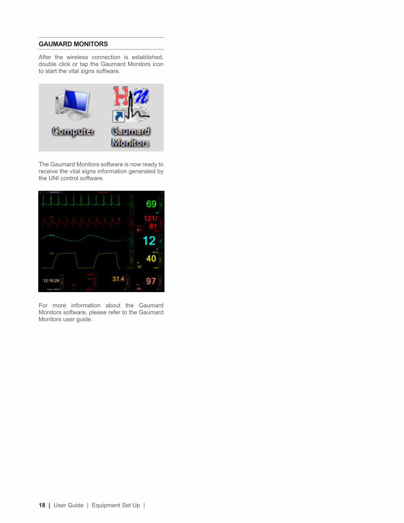
GAUMARD MONITORS
After the wireless connection is established, double click or tap the Gaumard Monitors icon to start the vital signs software.
The Gaumard Monitors software is now ready to receive the vital signs information generated by the UNI control software.
For more information about the Gaumard Monitors software, please refer to the Gaumard Monitors user guide.

| Working with Trauma HAL® | User Guide | 19
Working with
Trauma HAL®
20 | User Guide | Working with Trauma HAL® |
Airway
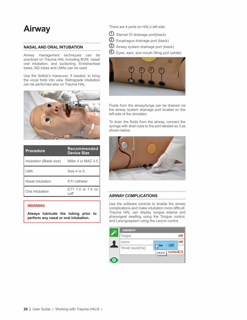
NASAL AND ORAL INTUBATION
Airway management techniques can be practiced on Trauma HAL including BVM, nasal/oral intubation, and suctioning. Endotracheal tubes, NG tubes and LMAs can be used.
Use the Sellick’s maneuver, if needed, to bring the vocal folds into view. Retrograde intubation can be performed also on Trauma HAL.
ProcedureRecommended Device Size
Intubation (Blade size) Miller 4 or MAC 3.5
LMA Size 4 or 5
Nasal Intubation 8 Fr catheter
Oral Intubation ETT 7.0 or 7.5 no cuff
WARNING
Always lubricate the tubing prior to perform any nasal or oral intubation.
There are 4 ports on HAL’s left side:
1 - Sternal IO drainage port(black)2 - Esophagus drainage port (black)3 - Airway system drainage port (black) 4 - Eyes, ears, and mouth illing port (white)
Fluids from the airway/lungs can be drained via the airway system drainage port located on the left side of the simulator.
To drain the luids from the airway, connect the syringe with drain tube to the port labeled as 3 as shown below.
AIRWAY COMPLICATIONS
Use the software controls to enable the airway complications and make intubation more dificult. Trauma HAL can display tongue edema and pharyngeal swelling using the Tongue control, and Laryngospasm using the Larynx control
4 23 1

| Working with Trauma HAL® | User Guide | 21
RIGHT MAINSTEM INTUBATION
The airway mechanism detect the placement of the endotracheal tube. If the endotracheal tube is inserted too deep, the left lung is disabled automatically demonstrating right mainstem intubation. Correcting the tube position enables the left lung chest rise.
AIRWAY SOUNDS
Trauma HAL can produce audible airway sounds. Use the software controls to change the sound type and adjust the volume. Auscultate using a standard stethoscope.
SURGICAL AIRWAY
Trauma HAL includes two replaceable surgical airway inserts. The inserts allow users to perform tracheostomy or cricothyrotomy procedures with real medical equipment. The surgical inserts feature anatomical landmarks. Also, a simulated cricothyroid membrane, and trachea skin cover are provided.
A separate ventilation insert is pre-installed, which is designed to maintain a tight air seal during ventilation and intubation exercises. Interchange the airway inserts as needed.
WARNING
Do not perform surgical exercises on the ventilation insert
1 Trachea skin cover
2 Simulated cricothyroid membrane
3 Surgical trachea assembly
4 Surgical cricoid insert
5 Ventilation insert
The assembly of surgical cricoid and trachea inserts allows for the use of tactical cricothyrotomy and tracheostomy kits.
Perform lateral or medial incisions on the replaceable trachea skin covers.
The cricoid assembly lexes providing realistic resistance when using a tracheal hook.
Place a tracheal tube then ventilate to observe chest rise and fall.
INSTALLING SURGICAL CRICOID INSERT, CRICOTHYROID MEMBRANE, AND SKIN
To install the surgical cricoid insert and the cricothyroid membrane:
1. Remove the ventilation airway insert by pulling on the ribbons located on either side
2. Adjust the ribbons to accommodate the surgical neck insert
2 43 51
22 | User Guide | Working with Trauma HAL® |
3. Place the surgical cricoid insert inside the cavity with the opening towards the head and gently press it down into position.
4. Remove the paper cover from the simulated cricothyroid membrane
5. Place the simulated cricothyroid membrane onto the insert and secure it by stretching the precut holes around the pins as shown below
6. Place the trachea skin cover over the assembly inserting the holes around the 4 pairs of pins.
The surgical assembly is ready to perform cricothyrotomy procedures.
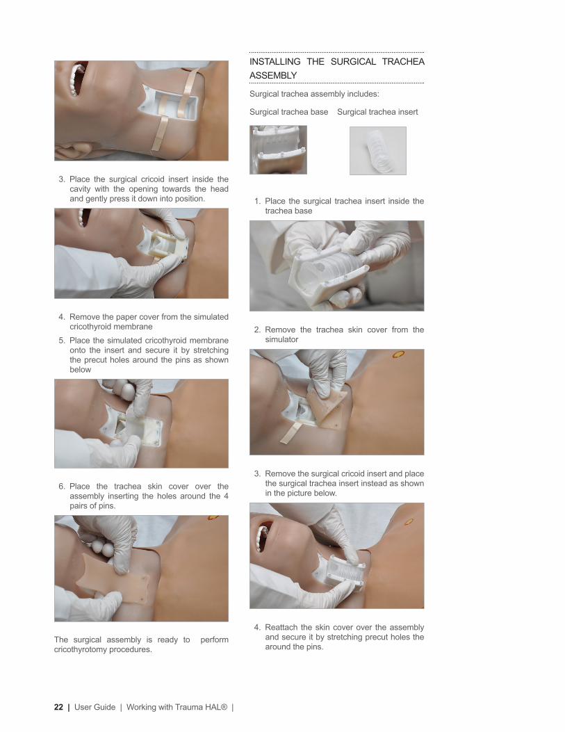
INSTALLING THE SURGICAL TRACHEA ASSEMBLY
Surgical trachea assembly includes:
Surgical trachea base Surgical trachea insert
1. Place the surgical trachea insert inside the trachea base
2. Remove the trachea skin cover from the simulator
3. Remove the surgical cricoid insert and place the surgical trachea insert instead as shown in the picture below.
4. Reattach the skin cover over the assembly and secure it by stretching precut holes the around the pins.

| Working with Trauma HAL® | User Guide | 23
VENTILATION CALIBRATION
The ventilation calibration wizard records the performance average of ive ventilations as the benchmark for correct ventilation. Perform the actions requested by the calibration wizard following the most current CPR guidelines. The CPR window evaluates provider performance based on the benchmark recorded during the calibration process.
To calibrate the ventilation performance benchmark using the UNI software:
1. Click Setup > Calibration > Ventilations, and click “Next”
The wizard prompts to perform ventilation “#1”
2. Perform the irst ventilation. A green illed oval indicates that the ventilation was recorded successfully
3. Perform ventilation # 2 as prompted by the wizard. A green illed oval indicates that the ventilation was recorded successfully
4. Continue through the calibration wizard to record a total of ive ventilations
At the end of the calibration process, the wizard reports the average peak, pressure, and duration values for the procedure. Click “Save” to store the calibration settings.
BREATHING PATTERNS
Control the respiratory rate, pattern, and inspiration percentage using the software controls. The breathing patterns are synchronized with the lung sounds and chest rise.
Trachea skin cover, cricothyroid membrane, and surgical trachea insert are consumable items.
Breathing
BILATERAL CHEST RISE
Bilateral chest rise and fall is automatic. Use the software controls to enable or disable the lungs independently and to adjust the breathing rate and the inspiratory percentage.
LUNG SOUNDS
The simulator generates audible upper, lower, anterior lung sounds. Use the software controls to select between the available respiratory sounds and to adjust the volume of each lung independently. The respiratory sounds include normal, wheezing, inspiratory squeaks, crackles, and rales.
PULMONARY VENTILATION
Set the respiratory rate to 0 and ventilate the simulator using a standard bag valve mask. Open the CPR window to monitor the provider’s ventilation performance in real time. Complete the ventilation calibration process before using the ventilation feature for the irst time

24 | User Guide | Working with Trauma HAL® |
REAL CO2 EXHALATION (OPTIONAL)
Trauma HAL can exhale real CO2 with the use of a CO2 cartridge. Once a CO2 cartridge is installed in the simulator, use the software controls to adjust volume of CO2 exhaled. Trauma HAL can also be operated without a CO2 cartridge installed. A virtual CO2 value is displayed on the virtual monitor PC.
Due to shipping regulations, CO2 cartridges are not included with the system. The required 16g threaded CO2 3/8”-24UNF-2A cartridges can be purchased at most bicycle or hardware stores. 12g threaded cartridges are also compatible with the CO2 feature.
CO2 SAFETY AND WARNING CHECKLIST
Review the safety and warning checklist information before using the CO2 feature. Failure to comply with the warnings listed below and those included with the original cartridge packaging may result in serious personal injury.
• Always follow the manufacturer’s safety and warning information included with the CO2 cartridge package.
• Never point a CO2 cartridge at yourself or others
• Do not use damaged CO2 cartridges
• Do not puncture the cartridge CO2 seal manually
• Do not expose the CO2 cartridges to high temperatures as indicated on the product’s packaging
• Install threaded cartridges only (3/8”-24UNF-2A). Do not attempt to install a cartridge that does not meet the speciications listed in this document.
• Do not over tighten the cartridge into the simulator’s cartridge harness
• Always verify that the CO2 cartridge is empty using the software diagnostics before removing it. Do not remove the CO2 cartridge if the simulator is not fully operational.
INSTRUCTIONS FOR USE
For maximum duration, connect the CO2 cartridge just before the simulation begins. If a CO2 cartridge is installed and left overnight, it will empty within 24 hrs whether it is used or not.
To install a new CO2 cartridge:
1. Remove the right leg skin cover and the tibia bone insert.
NEEDLE DECOMPRESSION
Needle decompression sites are located bilaterally at the 2nd intercostal space. Shallow decompression will result in audible air hiss. Internal sensors detect the 3.25 inch decompression needle and automatically change the lung function from the disabled to enabled state.
The lung must be in the disabled state before it can be treated with a decompression needle.
HEMOTHORAX SITES
Bilateral chest drain sites located in the 5th intercostal space allow for pneumo or hemothorax exercises. The hemothorax sites support 32 French straight thoracic catheters only.
WARNING
Use the hemothorax sites for placement exercises only. Do not introduce luid to the hemothorax sites.

| Working with Trauma HAL® | User Guide | 25
ADJUSTING CO2 OUTPUT
After the cartridge installed, adjust the Lung CO2 parameter to adjust the volume of exhaled CO2.
The graph below outlines the duration of CO2 output for each of the programmable CO2 levels with following parameters: RR=13, Compliance= 8, Airway Resistance=0, VT = 550.
CO2 LevelApproximate KPa
Approximate duration(in minutes) of CO2
0 0
1 1.7 125
2 2.8 110
3 3.9 75
4 4.7 55
5 5.5 45
6 6 35
2. Remove the harness adapter located inside the right lower leg chamber.
3. Screw in a new CO2 cartridge into the harness adapter. The harness adapter will puncture the CO2 seal as the cartridge is tightened. The cartridge will feel cool to the touch when the seal is broken. Continue to tighten the CO2 cartridge until is secured.
WARNING
Do not unscrew the cartridge once the seal is broken..
4. Insert the adapter into the chamber and replace the tibia insert and skin.

26 | User Guide | Working with Trauma HAL® |
ECG MONITORING AND ELECTRICAL
THERAPY
Trauma HAL is equipped with conductive skin sites that allow the attachment of real electrodes and deibrillator pads. This feature permits the user to track cardiac rhythms and events with their own equipment just like with a human patient. Trauma HAL can be shocked or paced with real energy for cardioversion, deibrillation and pacing drills. AED will display Trauma HAL’s ECG, analyze his cardiac rhythm and advise action.
WARNING
Deibrillation is only supported on the large sternum and apex sites circled RED below. Do not deliver a shock to ECG electrode sites on the shoulders or waist marked GREEN. The warranty does not cover damage to the simulator caused by applying electrical therapy to the ECG sites.
For exercises that incorporate real electrical therapy of any kind, always follow the safety guidelines and operating procedures outlined in the medical device manufacturer documentation.
4 LEAD CHEST SKIN
REMOVING AN EMPTY CO2 CARTRIDGE
A “Low CO2!” notiication is displayed on the left lower corner of the UNI software when low CO2 pressure is detected in the cartridge
Go to Setup> Calibration> Factory Settings and click “CO2 Pressure” to view the cartridge pressure reading. Replace the CO2 cartridge when the pressure reading reports 0.0 psi.
Do not remove the cartridge if pressurized CO2 is being reported. Allow the CO2 cartridge to empty before attempting to remove it.
Unscrew the empty CO2 cartridge slowly. If CO2 starts to escape, STOP unscrewing the cartridge and allow the remaining CO2 to escape before removing the cartridge completely.
WARNING
Never point the CO2 cartridge at yourself or others
Cardiac
HEART SOUNDS
Trauma HAL generates audible heart sounds (normal, distant, systolic murmur, S3 and S4) which are tied to a user deined heart rate and selectable rhythms. Use the software controls to change the heart sound type and volume level.
| Working with Trauma HAL® | User Guide | 27
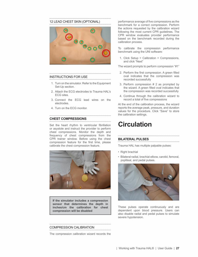
performance average of ive compressions as the benchmark for a correct compression. Perform the actions requested by the calibration wizard following the most current CPR guidelines. The CPR window evaluates provider performance based on the benchmark recorded during the calibration process.
To calibrate the compression performance benchmark using the UNI software:
1. Click Setup > Calibration > Compressions, and click “Next”
The wizard prompts to perform compression “#1”
2. Perform the irst compression. A green illed oval indicates that the compression was recorded successfully
3. Perform compression # 2 as prompted by the wizard. A green illed oval indicates that the compression was recorded successfully
4. Continue through the calibration wizard to record a total of ive compressions
At the end of the calibration process, the wizard reports the average peak, pressure, and duration values for the procedure. Click “Save” to store the calibration settings.
Circulation
BILATERAL PULSES
Trauma HAL has multiple palpable pulses:
• Right brachial
• Bilateral radial, brachial-elbow, carotid, femoral, popliteal, and pedal pulses.
These pulses operate continuously and are dependent upon blood pressure. Users can also disable radial and pedal pulses to simulate severe hypotension.
12 LEAD CHEST SKIN (OPTIONAL)
INSTRUCTIONS FOR USE
1. Turn on the simulator. Refer to the Equipment Set-Up section.
2. Attach the ECG electrodes to Trauma HAL’s ECG sites.
3. Connect the ECG lead wires on the electrodes.
4. Turn on the ECG monitor.
CHEST COMPRESSIONS
Set the heart rhythm to ventricular ibrillation or asystole and instruct the provider to perform chest compressions. Monitor the depth and frequency of chest compressions from the CPR trainer window. Before using the chest compression feature for the irst time, please calibrate the chest compression feature.
If the simulator includes a compression sensor that determines the depth in inches/cm the calibration for chest compression will be disabled
COMPRESSION CALIBRATION
The compression calibration wizard records the

28 | User Guide | Working with Trauma HAL® |
pressure and click “Next”
2. Set the pressure on the BP cuff to 0 (i.e. cuff valve open) as prompted by the calibration wizard.
3. Click the “OK” button to record the current cuff pressure for the interval. A green illed oval indicates the pressure interval was recorded successfully.
4. Set the pressure on the BP cuff to 20 mmHg as prompted by the wizard and then Click “OK” to record.
Continue increasing the BP cuff pressure as indicated by the prompt and recording the pressure intervals.
At the end of the calibration wizard, click “Finish” to close the calibration wizard.
BILATERAL IV ARMS
Trauma HAL has bilateral IV training arms that can be used for bolus or intravenous infusions as well as for drawing luids. There is also an antecubital venous access at the elbow bend in both arms.
PROGRAMMABLE BLOOD PRESSURE
Programmable blood pressure can be measured on the right arm using any standard sphygmomanometer. Korotkoff sounds are heard between systolic and diastolic pressure readings.
INSTRUCTIONS FOR USE
1. Place the cuff around the simulator’s upper right arm with the cuff mark at the medial site of the bicep brachii, about an inch (two cm) above the anterior elbow.
WARNING
Placing the cuff any differently might give an incorrect reading.
2. Inlate the BP cuff, and auscultate Korotkoff sounds just as with normal patient.
BLOOD PRESSURE CALIBRATION
Before starting the calibration process, place the blood pressure cuff on the simulator as it would be placed on a real human patient.
To calibrate the blood pressure feature using UNI software:
1. Click Menu> Setup> Calibration> Blood

| Working with Trauma HAL® | User Guide | 29
5. Close the clamp or disconnect the drain tube and continue injecting luids to the system until the syringe starts making resistance.
6. Disconnect the syringe with tubing and the drain tube (if it’s still connected). Vasculature system is ready to use.
7. To simulate a patient with no accessible peripheral IV sites, connect only the syringe. Pull the plunger to create suction, which will collapse the veins. Disconnect the syringe tube from the arm port while maintaining suction. The port will seal, and the veins will remain collapsed.
CLEANING THE VASCULATURE
Clean and dry the forearm vasculature at the end of the simulation session to prevent mold or clogs.
To clean and dry the IV arm:
1. Power on the simulator
2. Fill the illing syringe with alcohol 70%
3. Connect the ill syringe and the drain tube to arm
4. Flush the vasculature with 70% isopropyl alcohol solution.
5. Fill the illing syringe with air and purge the clean water to dry the vasculature.
REPLACING ELBOW VENOUS LINE
To replace the elbow venous line follow the instructions:
WARNING
Do not attempt to ill IV system without the drain connector in place.
Always leave the drain port connected when injecting more that 40 ml of luids into the system.
Use only Gaumard’s provided simulated blood. Any other simulated blood brand containing sugar or any additive may cause blockage and/or interruption of the vasculature system.
Always lush the IV system with alcohol 70% at the end of every simulation.
INSTRUCTIONS FOR USE
1. First, locate the ill syringe with tubing (white connector) and the drain tube with pinch-clamp (black connector). Fill the syringe with the desired luid -- water or simulated blood.
2. Connect the drain tube with clamp to the black port as shown.
3. Connect the syringe with tubing to the white port
4. Leave the drain tube clamp opened and depress the syringe until all air has been pushed from the IV system and luid runs from the drain.
30 | User Guide | Working with Trauma HAL® |
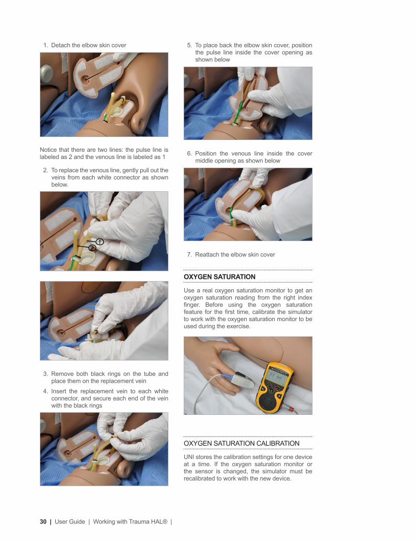
5. To place back the elbow skin cover, position the pulse line inside the cover opening as shown below
6. Position the venous line inside the cover middle opening as shown below
7. Reattach the elbow skin cover
OXYGEN SATURATION
Use a real oxygen saturation monitor to get an oxygen saturation reading from the right index inger. Before using the oxygen saturation feature for the irst time, calibrate the simulator to work with the oxygen saturation monitor to be used during the exercise.
OXYGEN SATURATION CALIBRATION
UNI stores the calibration settings for one device at a time. If the oxygen saturation monitor or the sensor is changed, the simulator must be recalibrated to work with the new device.
1. Detach the elbow skin cover
Notice that there are two lines: the pulse line is labeled as 2 and the venous line is labeled as 1
2. To replace the venous line, gently pull out the veins from each white connector as shown below.
3. Remove both black rings on the tube and place them on the replacement vein
4. Insert the replacement vein to each white connector, and secure each end of the vein with the black rings
21

| Working with Trauma HAL® | User Guide | 31
intensity.
ACTIVE EYES
The simulator is equipped with programmable blinking eyes and pupils that dilate. Use the software controls to change the blinking rate and to enable or disable pupil reaction.
PUPIL SENSITIVITY CALIBRATION
The eye reaction is factory calibrated. Use the “Pupil Sensitivity” controls to recalibrate the pupil reaction for the current room lighting only if needed.
To calibrate the pupil dilation:
From the File menu, go to Setup> Calibration> Pupil Sensitivity
• Click “Calibrate current ambient light” to recalibrate the pupil diameter to the current ambient light.
• Click “Calibrate low intensity light” to set the pupil diameter to low intensity light.
• Click increase or decrease to adjust the inetune pupil’s reaction to direct light
SEIZURES
The simulator is capable of convulsing to simulate
WARNING
Oxygen saturation monitors that detect carbon monoxide and/or methemoglobin are not supported.
To calibrate the oxygen saturation inger:
1. Turn OFF the oxygen saturation monitor and place the oximeter sensor on the right index inger. Verify that the right index inger is centered inside the inger sensor.
2. Go to Setup>Calibration and select “Oxygen Saturation”. Click “Next” to continue.
3. Turn ON the oximeter and click “OK” on the dialog box.
4. Adjust the reading on the oximeter monitor screen to match the value displayed on the GaumardUI calibration screen using the arrows on the left column of the calibration window. The irst calibration point is 98%.
5. Use the triple arrows to increase or decrease the reading on the oximeter in large intervals, double arrows for moderate changes, and the single arrows for small changes of one or two percent readings. Wait 10-15 seconds after making an adjustment to allow the oximeter reading to stabilize. Doing so ensures proper calibration.
6. After the reading on the OSAT monitor is stable and it matches the value on the GaumardUI calibration window, click “OK”, and then “Next” to continue.
7. Repeat the process to calibrate the following intervals.
Click “Finish” at the end of the calibration and remove the OSAT monitor from the inger.
INSTRUCTIONS FOR USE
1. Start UNI and establish communication with the simulator.
2. Connect the oximeter probe to the left index inger of the simulator.
3. Turn on the monitor.
4. Adjust the oxygen saturation using the UNI software controls.
Cephalic
CENTRAL CYANOSIS
Use the software controls to adjust the cyanosis

32 | User Guide | Working with Trauma HAL® |
on the left side of the simulator.
STERNAL IO ACCESS
The sternal intraosseous access site allows for the infusion of luids and medications into the bone marrow using FAST1® and FASTx® IO devices.
The sternal IO access site is a replaceable insert constructed from rigid material that simulates the density of real bone material.
To establish sternal IO access, follow the usage and placement guidelines outlined by the IO device documentation.
FeatureVolume Capacity
Sternal access site reservoir 20 cc
The IO sternal access site is connected internally to a drain port located on HAL’s left side.
During high volume infusions, connect the IV drain tube to the sternal IO drainage port to prevent overilling the sternum reservoir.
mild or severe seizures. Use the software controls to enable the seizure behavior.
Systemic
INTRAMUSCULAR INJECTION SITES
IM sites for placement exercises are located on both deltoids and quadriceps.
WARNING
Do not inject luids into the IM sites.
BOWEL SOUNDS
Use the bowel sound controls to change the bowel sound types and adjust the volume levels. Auscultate the bowel sounds using a real stethoscope.
GASTRIC DISTENSION
HAL can exhibit gastric distension if ventilated excessively. To relieve the gastric distension, press down on the stomach gently.
Fluids from the esophagus/gastric bag can be drained throughout the esophagus drainage port

| Working with Trauma HAL® | User Guide | 33
6. Insert the new IO sternal access site into the holder and secure it using the screw
7. Press the tube down irmly into the elbow to reconnect the drain tube
8. Fit the rib cage back into place
INTRAOSSEOUS ACCESS AT TIBIA
I/O access at Tibia is used for the infusion of luids, blood and/or drugs directly into the bone marrow of the tibia or other large bone. Setting up an intraosseous access line is an invasive procedure that can be simulated with the Trauma HAL.
REPLACING I/O STERNAL ACCESS SITE
To replace the IO sternal access site:
1. Turn off the simulator
2. Remove the chest skin
3. Lift the rib cage slightly to expose the IO sternal access drain tube
4. Press the elbow lange to unlock and disconnect the drain tube
5. Turn over the rib cage and unscrew the IO access site

34 | User Guide | Working with Trauma HAL® |
6. Palpate the tibial tuberosity.
7. Insert the bone aspiration needle below the tibial tuberosity. Note the sharp decrease in needle resistance as it passes into the bone marrow cavity. Remove stylet, aspirate bone marrow, and infuse luids.
WARNING
Always drain and lush the reservoirs after every simulation.
STREAMING AUDIO
Use the streaming voice to speak as the simulator’s voice and engage the provider in a realistic conversation.
INSTRUCTIONS FOR USE
Ensure that the headset and microphone is connected to the PC before starting the UNI software. The headset minimizes echo and environmental noise to improve audio quality.
The following procedure describes how to use the I/O access feature:
1. Remove tibia cover from the right leg to access the two part tibia.
2. Gently remove both halves of bone, starting with the lower half
3. Fill the upper and lower half of tibia with luid using the orange adapter connected to the illing syringe.
4. Replace tibia bone in the leg.
5. Re-attach the tibia cover.

| Working with Trauma HAL® | User Guide | 35
the digital UNI user guide under Menu/Help/Instruction Manual.
PROGRAMMABLE EAR, EYE, AND
MOUTH FLUID SECRETIONS
Ear, eye, and mouth luid secretions can be activated independently using the software controls.
To ill the luid secretion reservoir:
1. Locate the black illing port on the left side of the simulator.
2. Fill the illing syringe from the IV illing kit with the desired luid
3. Connect the illing syringe to the black illing port
4. Fill the luid reservoir with a maximum
volume of 100 cc
FLUID RESERVOIR
HAL’s internal luid reservoir holds 1.5 liters of simulated blood. The internal reservoir is
Click the “talk” icon and speak into the headset to talk as the simulator’s voice.
To listen to the provider’s response, click “Listen”.
Refer to the digital UNI user guide under Menu/Help/Instruction Manual for more information on additional streaming voice features and functions.
TraumaTrauma HAL is capable of bleeding from the axillary wound, groin wound, and the trauma limbs. Also, ear, mouth and eye luid secretions can be programmed. Manually activate the bleeding and secretion functions using the UNI controls or program the actions into a scenario. For more information about scenarios, refer to

36 | User Guide | Working with Trauma HAL® |
5. Hold the luid tank at least 2 feet above Trauma HAL’s internal reservoir to prevent back pressure in the line and open the low valve
6. On the UNI software’s right vertical bar, select the “Fluid Reservoir “icon.
7. Click the “Fill” button to start the auto-ill pump
equipped with a volume sensor and pump that draws luid from the external illing bag.
Feature Type Volume (L)
Internal Fluid reservoir
Gaumard Simulated Blood
1.5
PREPARING THE EXTERNAL BLOOD FILLING BAG
To ill the internal blood reservoir with simulated blood:
1. Mix the Gaumard artiicial blood substitute on a separate container following the directions printed on the bottle’s label.
To prevent clogging, be sure to dissolve the simulated blood compound in the water completely.
2. Close the external blood illing bag low valve and ill the bag with the artiicial blood solution.
3. Open the low valve to purge all the air in the line and close it when luid begins to exit
FILLING THE FLUID RESERVOIR
To ill Trauma HAL’s internal reservoir with simulated blood:
1. Turn the simulator on
2. Connect the ill syringe to the internal reservoir port located on the inner left thigh and vacuum any air or luid present
3. Disconnect the ill syringe
4. Connect, turn, and lock the external blood bag to the ill port located on the inner left thigh

| Working with Trauma HAL® | User Guide | 37
WARNING
To prevent clogging, purge the system with clean water after simulation is complete. Doing so will prevent clogging and molding in the internal vasculature and the wound sites.
Pack Trauma Gauze in the axillary and groin wound sites to stop the bleeding.
Pressure sensors are also located at the axillary wound, femoral artery and the groin wound.
TRAUMA CALIBRATION
To calibrate the amount of pressure needed to stop the bleeding at the wound site:
1. Turn on the simulator.
2. Locate the region you would like to calibrate.
3. Go to the Setup menu and click on Calibration.
4. The Calibration dialog box is displayed. Select Trauma and click “Next”.
5. Select the trauma region you would like to calibrate and click “Next”.
6. Follow the instructions and apply direct pressure over the would.
7. Click “OK” while applying constant pressure over the would.
8. The word “Done” will lash in the middle of the window, and the oval will ill green temporarily.
Please wait while the internal reservoir is illed. The internal pump will stop automatically when the reservoir reaches the maximum capacity. Alternately, the illing process can be stopped manually clicking the “Stop” button
8. Disconnect the blood reservoir tank
The system is ready for use. The right hand column in the luid reservoir window will show the percentage of blood lost during the trauma simulation. To clear the blood lost value and start over again, click the “blood lost (clear)” button)
WOUND SITES
The axillary and groin wounds inserts bleed simulated blood when activated. Sensors located in the wound insert cavities detect pressure applied by the provider and stop blood low automatically.

38 | User Guide | Working with Trauma HAL® |
controlled heart rate and blood pressure
• Apply a tourniquet over the sensor line to stop bleeding
TRAUMA ARM INSTALLATION
To install the trauma arm:
1. Remove the elbow bolt from the arm and gently separate the healthy lower arm to expose the pulse tubing
2. Disconnect the green pulse tubing from the healthy lower arm
3. Connect, turn, and lock the clear luid line to the trauma arm
4. Insert the disconnected pulse lead into the
9. After a few seconds, the “Finish” button will be enabled and the oval will default back to gray.
10. Click “Finish” to save the new calibration.
REPLACING THE WOUND INSERTS
To install the healthy insert:
1. Gently lift the wound site out of the cavity to expose the luid line
2. Turn and unlock the connector to detach the wound site luid line
3. Press the luid line into the cavity
4. Press the healthy insert into the cavity evenly
TRAUMA ARM
Interchange healthy arms with the trauma forearms. Use the software controls to activate the left or right arm bleeding.
TRAUMA ARM FEATURES
• Pulsatile bleeding from arteries
• Blood-low is consistent with software-
| Working with Trauma HAL® | User Guide | 39
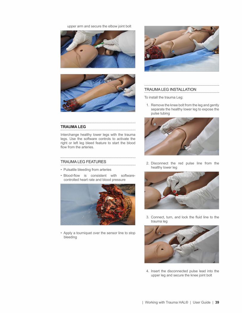
TRAUMA LEG INSTALLATION
To install the trauma Leg:
1. Remove the knee bolt from the leg and gently separate the healthy lower leg to expose the pulse tubing
2. Disconnect the red pulse line from the healthy lower leg
3. Connect, turn, and lock the luid line to the trauma leg
4. Insert the disconnected pulse lead into the upper leg and secure the knee joint bolt
upper arm and secure the elbow joint bolt
TRAUMA LEG
Interchange healthy lower legs with the trauma legs. Use the software controls to activate the right or left leg bleed feature to start the blood low from the arteries.
TRAUMA LEG FEATURES
• Pulsatile bleeding from arteries
• Blood-low is consistent with software-controlled heart rate and blood pressure
• Apply a tourniquet over the sensor line to stop bleeding

40 | User Guide | Working with Trauma HAL® |
INTERCHANGEABLE MALE GENITALIA
The simulator features interchangeable male genitalia.
To install the male genitalia, insert the male genitalia urethra tube into the catheter port. Ensure the connector is secured to prevent leaks.
INSTRUCTIONS FOR USE
Catheterize the simulator using an 18 Fr catheter lubricated with mineral oil. At the end of the exercise, drain the luid from the bladder reservoir to prevent mold.
Other
VITAL SIGNS MONITOR (OPTIONAL)
The vital signs monitor simulates a vital signs monitor attached to the simulated patient. The vital signs are synchronized through a wireless network between the facilitator’s tablet and the computer running the monitor. You can customize each trace independently of each other; users can set alarms, time scales, boundaries and grid options.
URINARY CATHETERIZATION
Trauma HAL features an internal bladder used for catheterization exercises
INSTRUCTIONS FOR USE
To set up your Trauma HAL for urinary catheterization, follow the steps below:
1. Unfasten the mid-section skin from the abdominal region.
2. Connect the IV ill Syringe to the one way valve located on the right side of the simulator.
3. Fill the bladder bag with a maximum volume of 240 mL
4. Remove the syringe and re-attach the midsection skin.
The luids can be drained out using a urinary catheter size 18Fr.

| Working with Trauma HAL® | User Guide | 41
For more information on using the Wound Kits, refer to the documentation included with the upgrade option.
PRO+ (OPTIONAL)
The Pro+ system is an all-in-one session recording and simulator control solution for facilitators in a lab or mobile environment. The built in UNI software allows the facilitator to control Trauma HAL while recording care provider interaction and event logs. The upgrade replaces the standard tablet with a convertible touchscreen laptop loaded with the Pro+ environment and UNI, (2) WI-FI enabled cameras, (1) motorized 180 view USB camera and carrying case. For more information, refer to the documentation included with the upgrade option.
For more information on using the Pro + system, refer to the documentation included with the upgrade option.
WOUND KITS (OPTIONAL)
Wound Kits assist health professionals in training exercises simulating community disasters, disasters of war, and multiple burn injury types.
WOUND KIT FEATURES
• Sized to it Gaumard adult simulators
• Specially formulated silicone provides realism not seen in vinyl casualty kits
• Tough and resilient
• Speciic light, medium, or dark skin tone kits are available at no extra charge.
Four different wound kits are available. These include:
• Casualty Wound Kit
• Emergency Wound Kit
• Trauma Wound Kit
• Burns Wound Kit

42 | User Guide | Working with UNI™ |
Working with UNI™

| Working with UNI™ | User Guide | 43
Initializing the
SimulatorAfter reading the manufacturer’s care and caution information, press the power button to turn on the Tablet PC.
The UNI software initializes the simulator. Double click the UNI icon on the tablet’s home screen to start.
The simulator selection menu is shown. Select Trauma HAL and click “Start”.
The wireless link between UNI and the simulator is established within 1 minute.
PROFILES AND OPERATING MODES
After the startup screen, the proile and operating mode selection menu is displayed.
The UNI control software has two modes of operation: Manual and Automatic. Each mode includes a Quick Start proile with preprogrammed scenarios created in conjunction with experienced healthcare instructors and working medical professionals. Continue to the next section to learn more about each operating mode and the proiles included.
After selecting an operating mode and proile, click “Load” to continue.
MANUAL MODE
In the “Manual” operating mode, the facilitator fully controls the vital signs and physiologic responses.
The Manual mode includes the following proiles:
DEFAULT PROFILE
Includes one preprogrammed palette with healthy vital signs

44 | User Guide | Working with UNI™ |
QUICK START TRAUMA HAL
Includes eight scenarios. For scenarios description refer to the Appendix.
AUTOMATIC MODE
The Automatic mode assists the facilitator by automatically adjusting vital signs in response to caregiver participation, pharmacologic intervention, and manual input. For example, when facilitator increases the heart rate, the auto mode will calculate the response and adjust the blood pressure automatically. To activate the operating mode as an upgrade option, go to “Menu” section.
The Automatic mode includes the following built-in proiles:
DEFAULT MODELING
Includes one preprogrammed palette with healthy vital signs
MEDS PROFILES
Includes a library of pre-programmed drugs to be used on simulations.
QUICK START HAL MODELING
Includes a library of pre-programmed scenarios conigured for the automatic operating mode
MANAGING PROFILES
Use the Manage Proile Menu to create a new proile and edit this proile.
Also the proile folder location will be shown below the “New Proile” icon.
Use the “Map Proiles folder“ icon to select the location of the new proile to be created on the server.
Select the server location and click “Make New Folder” to create the proile folder.
Assign a name to the folder and click “OK”
The new proile folder location will show up. Then proceed to create a new proile, see instructions detailed below.
Use the “Home” icon to reset to default proiles folder.

| Working with UNI™ | User Guide | 45
Click “Rename” or “Delete” to change the name of delete this new proile
UNI InterfaceThe UNI software is used control the simulator, monitor the vital signs, and evaluate the provider’s performance. The simulation technician or instructor carrying out the simulation operates the UNI software.
The UNI control elements and scenario programming procedures are consistent throughout the Gaumard family of high idelity simulators. Some software controls and features covered in this guide may be hidden depending on the simulator’s hardware coniguration and optional upgrades.
CREATING A NEW PROFILE
Proiles store palette, scenario, and option settings independently; changes made to one proile have no effect on the others. Below are some examples on how proiles are used.
• Assign one proile to each user of your Gaumard simulator system
• Use proiles to organize and protect palettes and scenarios
• Create a proile dedicated to a speciic academic course taught by multiple instructors
• Devote an entire proile to one particular subject area, or even one particular scenario
To create a new proile, click “New Proile”.
Enter a name for the new proile followed by a description.
Enable the PIN protection to prevent unauthorized users from accessing or making changes to this proile.
Lastly, click “Create” to save the new proile.

46 | User Guide | Working with UNI™ |
CONNECTION STATUS
The communication indicator displays the status of the radio link between the tablet’s USB RF module and the simulator. Full bars indicate excellent communication (i.e., normal operation).
BATTERY INDICATOR
The battery status indicator progresses as the battery in the simulator is used. The exclamation mark indicator is shown when there is no communication and battery information cannot be retrieved.
When the battery icon is depleted, the simulator is set to STAND-BY mode automatically to protect some of the simulator’s internal components. Simulator will not initialize until connected to the charger or the battery is replaced with a fully charged spare.
Internal battery duration is approximately 10 hours
WARNING
Turn Simulator OFF before replacing the battery. Failure to do so could result in serious damage to the system.
SESSION CLOCK
The session timer allows the facilitator to maintain a chronological record for individual simulation sessions. The session timer can be reset from the ile menu when a new simulation session begins, or by clicking the session time icon and then Reset Session Clock. Events during the simulation are logged in accordance to the session time.
POWER/STAND-BY BUTTON
The standby button is located on the bottom right corner of the UNI software. Use the stand-by feature to conserve battery during lectures.
FLUID RESERVOIR
The “Fluid Reservoir” panel displays the amount of luid stored in the internal blood reservoir. To

| Working with UNI™ | User Guide | 47
STATUS/DETAILS CONTROLS
The Status/Details panel is used to monitor and control the simulator’s vital signs. The individual parameter controls displayed on the details tab provide the simplest method for controlling the simulator’s vital signs, sounds, and features.
The Status/Details tab displays the vital signs controls in a list format.
SYSTEMS LIST VIEW
The vital signs controls are divided into separate categories. Click through the categories to view the controls available for the current simulator coniguration.
access this panel, click the “Fluid Reservoir” icon on the right vertical menu
The “Fill” button activates the internal pump for drawing luids into the internal blood reservoir. The internal pump will stop automatically when the reservoir has illed. Alternatively, click “Stop” to turn off the pump manually.
When the bleeding features are activated, the “blood lost” graphic displays an estimate of the blood volume lost in real time. Click “Blood lost (clear)” to reset the counter before illing up the reservoir with luid again, to get readings that are more accurate.
For information on how to ill the system with simulated blood, refer to the “Working with Trauma HAL” section.

48 | User Guide | Working with UNI™ |
Click the slider control below the sound library to adjust the volume of the sounds.
APPLYING CHANGES
No changes will be made to the simulator’s condition until the new settings are submitted using the “Apply” panel.
After the list of changes is created, click “NOW” to update the vital signs instantly. Alternatively, click a trending timer to update numerical vital sign parameters (e.g. heart rate, blood pressure) gradually.
CHANGING VITAL SIGNS
To adjust numerical values click the slider control. (e.g. heart rate, blood pressure, respiratory rate, etc.).
Alternatively, use the keyboard for manual entry and click the green checkmark to conirm the change.
To change patterns, sounds, and rhythms, click on the speciic control to display the library (e.g. EKG rhythms, heart and lung sounds,respiratory patterns, etc.)

| Working with UNI™ | User Guide | 49
Each trauma feature can be enabled or disabled independently.
CREATING PALETTE ITEMS
A palette item stores one or more vital sign settings into a single loadable object. Use a palette item to update a set of vital signs quickly. For example, one palette item can be created to update all the cardiac parameters to a healthy state.
To create a new palette item, set the values for the desired vital signs parameters using the details controls and click “Save”.
Vital sign parameters can be edited or removed using the edit and remove parameter tabs
Enable the “instant apply” option and click the control to change the vital sign to a new value without the need to use “Apply” panel. Vital signs undergoing change blink yellow.
TRAUMA
The Trauma is the last option from the category menu and includes:
• Eye Fluids
• Ear Fluids
• Mouth Fluids
• Left Arm Bleed
• Right Arm Bleed
• Left Leg Bleed
• Right Leg Bleed
• Axilla Bleed
• Groin Bleed

50 | User Guide | Working with UNI™ |
Click the apply option to submit the changes.
For more information about the UNI software, refer to the digital UNI User Guide under Menu/Help/Instruction Manual.
Enter a name for the palette, a description, and choose color code. Click “Save” to create the new palette Item. Palette items are stored in the active proile.
When the palette is needed, click the Load button to select the palette from the library.
Select the palette item from the “Load Palette Item” menu and click “Load”

| Appendix | User Guide | 51
Appendix

52 | User Guide | Appendix |
More about Scenarios
THINKING IN TERMS OF PALETTE ITEMS
As described previously, palette items represent complete or partial groups of settings that have been stored as a single item. Applying partial states will hold constant all settings that are left unspeciied.
Not only does it take time to customize the palette, but a very large palette becomes dificult to navigate. So, it is desirable to minimize the number of Palette Items in each Proile. To accomplish this, an experienced facilitator tries to create items that are as generally applicable as possible and can therefore be applied to a wide range of scenarios. The key is to include only in your palette items the settings that are directly related to the physiological event represented by that palette item.
SMART SCENARIOS
After reading the Details, Palette, and Scenarios sections of this guide, it should be clear how to build a scenario. You may have already tried building your own or modifying some of the factory presets. The following four guidelines will reine your ability to build the best possible scenarios.
1. How will the scenario begin?
The irst thing to consider is the initial condition of the patient. Create a Palette Item to describe this condition. Make sure that this irst step in the scenario is a complete state. That is, indicate some selection for each available setting on the Details page. Remember that only the settings you specify will cause a change in Trauma HAL and all other settings will remain constant. Therefore, by starting with a complete state, Trauma HAL’s condition will always be the same when the scenario starts, regardless of what she was doing previously.
Likewise, the “transition duration” of the irst step in the scenario should be zero, indicating that changes are applied immediately.
There is one point that can cause confusion and warrants further explanation. It is an extension of the above discussion of partial states. The issue is best illustrated through the following example:
Suppose that you are creating a Palette Item to start your scenario. In this case, you have decided that the patient will be apneic. The question is, “How should the lung sounds be set?”
Most people’s irst inclination is to set the lung sounds to “none.” This is incorrect, despite apnea. Obviously, no lung sounds should be heard during apnea, but since you have already set respiratory rate to zero, none will be. (Sounds are synchronized to the breathing cycle.)
What you are really setting here when you choose a lung sound is the condition of the lungs, given respiratory drive. That is, if the patient’s respiratory rate were changed from zero, what sound would be heard? Assuming that the lungs themselves are normal in this scenario, you would choose “normal” for the lung sound setting.
Then, as the scenario progresses, if the patient starts breathing, there will be no need to set the lung sound again. It will already be set. The same principle applies to the heart sound and other settings.
2. Include notes to guide the facilitator during the simulation.
It is common for scenario designers, especially those who act as facilitators, to neglect the importance of notes in the scenario. They think that they will remember the learning objectives, patient history, and other details at the time they are ready to conduct the simulation. They usually do not, especially when revisiting a scenario months after creating it.
When you add “Wait” and “Wait Indeinitely” steps to a scenario, you have an opportunity to edit the item description. Use this description ield to hold notes to the facilitator. Typically, scenario designers write notes in that space to indicate what the provider(s) or facilitator should be doing at that point.
Further, when saving the scenario, you may edit the scenario description. This is the best place to put patient history and any other longer notes and instructions.

| Appendix | User Guide | 53
3. Assume that providers will do the right thing.
Usually a scenario should be created with the assumption that the providers will perform correctly. As long as they do, the scenario can be allowed to continue.
Naturally, preparation must be made for what might happen to Trauma HAL when providers deviate from expectations. The consequences of such deviations can sometimes be included in the scenario, punctuated by “Wait Indeinitely” items. In other cases, the simulation will require more direct control by the facilitator via either the Palette or Details page.
4. Choose auto-response settings based on the scenario content and the objectives.
As seen, auto-responses can be used to free the facilitators’ attention. They also enhance realism by presenting instant reactions to the care providers. On the other hand, sometimes it is not possible or desirable to determine the responses before the simulation begins. Different environments and applications call for different settings.
Some teaching practices are best done with the auto-response settings in Prompt mode. Responses must be triggered by a vigilant facilitator. Though it is slower and requires more attention, the beneit of Prompt over other modes is that the simulation can be allowed to go in any direction, and it will be possible to choose the response on a case-by-case basis.
Other learning exercises require a higher degree of automation. For such applications, most facilitators choose Auto mode for the auto-response settings. The key issue is standardized timing of symptom presentation. A consistent, repeatable simulation is essential for fair assessment of that care provider in relation to others and for the broader interpretation of results in the context of training validation studies.
When in doubt, it is best to choose Prompt mode, in which the facilitator will be given direct control of the responses as events are detected.
FACTORY PRESET SCENARIOS DESCRIPTION
MANUAL MODE
Scenario Name Scenario Description Type
1 Agent Poison After a detonation a team member falls to the ground twitching and foaming at the mouth.
Branching
2 Bradycardia For this scenario to function as intended the instructor should enable automatic pacing capture in the ‘Setup -> Auto-Responses’ menu. A in-hospital patient is diagnosed with Bradycardia and requires immediate attention.
Branching
3 Chest Pain Patient is having chest pain during physical training.
Branching
4 Pulseless Arrest A young male was found unconscious
Branching

54 | User Guide | Appendix |
5 Tachycardia- pulse
SVT with pulses. Note: this scenario can progress directly to the Pulseless Arrest scenario. To do so, load “Pulseless Arrest” after stopping this scenario while on Node 2.
Branching
6 Trauma- Airway Soldier has dificulty breathing, immediate response is required.
Branching
7 Trauma- Chest Soldier medic encounters a casualty on a vehicle that has been struck by an IED. Casualty is responsive, airway is patent, respirations are 32 per minute and a wound is noted in the left axilla. Patients pulse is rapid and requires rapid trauma assessment.
Branching
8 Trauma- Left Leg Soldier is injured on the leg with IED. Branching

| Appendix | User Guide | 55
Troubleshooting
GENERAL TROUBLESHOOTING GUIDE
SymptomPossible
CauseSolution
Communication with the simulator cannot be established or signal strength is weak
Battery is discharged
Reconnect simulator to the AC adapter to charge the battery. If the battery is completely discharged, connect the AC adapter and wait 20 before turning the simulator back on. Keep the AC adapter connected to the simulator during simulation to prevent interruptions.
Controlling computer is too far away from simulator
Minimize the distance between simulator and the tablet.
Interference caused by physical obstructions
Maintain line of sight with the simulator and direct the RF module towards the simulator
Attempting to communicate with a different simulator
Conigure UNI to connect to the simulator by serial number.
Controlling multiple simulators from a single controlling PC
Assign different communication channels for each of the simulators to prevent cross talk.
RF module is not detected by the controlling PC
Restart the controlling PC
AC adapter is damaged
Verify the power adapter LED to ensure the adapter is working. Disconnect the power adapter from the wall and the simulator and inspect the connector for damage or broken pins.
Simulator does not run on internal battery power
Battery is not charged
Ensure the AC adapter is connected to simulator and a working power outlet
Keep the AC adapter connected to the simulator during simulation to prevent interruptions.
Use only the AC adapter labeled with the simulator’s name. Do not use universal power adapters.
Simulator doesn’t respond to any com-mand although signal strength is excellent
UNI has established communication with a different simulator
Conigure UNI to connect to the simulator by serial number.
Simulator does not power or communication is never established (wired connectivity only)
Data cable is not connected.
USB communication Module is not connected.
Verify connection of the Ethernet cable and USB module to the computer’s USB port.
Wrong serial number entered in the options menu
From the menu bar, enter the simulator’s serial number in the Setup> Options> Environment tab
Power supply is disconnected
Connect the power supply to the simulator and restart the UNI software

56 | User Guide | Appendix |
Intubation is falsely detected
Intubation sensor requires recalibration
Remove any adjuncts from the airway and complete the reset procedure in the UNI menu>Setup>Calibration>Factory Settings> Reset ET tube.
Artiicial ventilations are not properly detected or not detected at all
Respiratory rate is not set to zero
Ventilations are not calibrated
Set the respiratory rate to zero
See “Calibration Wizard” .
Chest does not rise with artiicial ventilation (e.g. BVM)
Simulator not running
Turn the simulator on
Respiratory rate is not set to zero
Set the respiratory rate to zero
Air is escaping between the mask and the simulator’s skin
Maintain a tight seal between the BVM mask and the simulator
Low chest rise (or no chest rise at all) while breathing
Respiratory pattern is set to apnea
Change the respiratory pattern to a healthy pattern
Inspiratory percentage is set to a low value
Set Respiration Rate to 13, and Inspiratory Time to 33%
Pupils are reacting erratically
Eyes are not calibrated for the current environment
Recalibrate the pupil dilation for the current ambient light. Go to UNI Menu>Setup Calibration> Pupil Sensitivity.
Chest compressions are not detected
Heart rhythm is set to sinus
Set the heart rhythm to a critical heart rhythm
Compression sensor is not calibrated
Calibrate the chest compressor using the UNI Menu>Setup> Calibration> Chest Compressions
No left radial pulse Radial pulses are disabled
Enable the radial pulses using the details controls
Blood pressure values are require calibration
Go to UNI Menu> Setup> Calibration>Blood Pressure Cuff
Preprogrammed scenarios are not available
Load the “Quick Start Simulator” proile.
To switch between proiles without exiting the software, Click File>Proile on the menu bar.
The simulator’s audible features (heart, lung, Korotkoff, etc.) are low or cannot be heard at all
Audio feature volume is set to mute or low
Adjust the volume levels on the status panel
Streaming audio quality is poor or echo
Headset is disconnected
Close UNI and connect the MIC and Headphone jacks into the designated ports on the laptop. Restart the software.
Headset connectors are connected to the wrong portsHeadset is not recognized by UNI
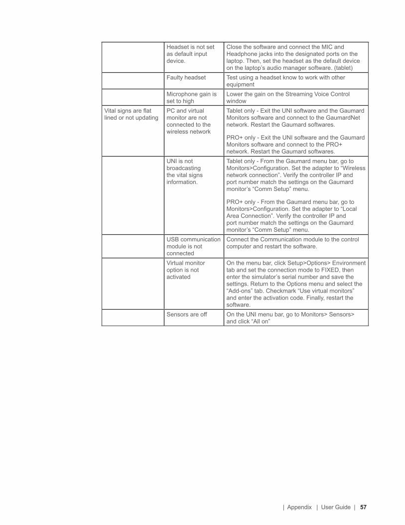
| Appendix | User Guide | 57
Headset is not set as default input device.
Close the software and connect the MIC and Headphone jacks into the designated ports on the laptop. Then, set the headset as the default device on the laptop’s audio manager software. (tablet)
Faulty headset Test using a headset know to work with other equipment
Microphone gain is set to high
Lower the gain on the Streaming Voice Control window
Vital signs are lat lined or not updating
PC and virtual monitor are not connected to the wireless network
Tablet only - Exit the UNI software and the Gaumard Monitors software and connect to the GaumardNet network. Restart the Gaumard softwares.
PRO+ only - Exit the UNI software and the Gaumard Monitors software and connect to the PRO+ network. Restart the Gaumard softwares.
UNI is not broadcasting the vital signs information.
Tablet only - From the Gaumard menu bar, go to Monitors>Coniguration. Set the adapter to “Wireless network connection”. Verify the controller IP and port number match the settings on the Gaumard monitor’s “Comm Setup” menu.
PRO+ only - From the Gaumard menu bar, go to Monitors>Coniguration. Set the adapter to “Local Area Connection”. Verify the controller IP and port number match the settings on the Gaumard monitor’s “Comm Setup” menu.
USB communication module is not connected
Connect the Communication module to the control computer and restart the software.
Virtual monitor option is not activated
On the menu bar, click Setup>Options> Environment tab and set the connection mode to FIXED, then enter the simulator’s serial number and save the settings. Return to the Options menu and select the “Add-ons” tab. Checkmark “Use virtual monitors” and enter the activation code. Finally, restart the software.
Sensors are off On the UNI menu bar, go to Monitors> Sensors> and click “All on”

58 | User Guide | Appendix |
Pro+ System Ofline Updater (If Applicable)
INSTRUCTIONS FOR USE
1. Head to www.Gaumard.com
2. Click the Software Updates button located on the middle right, under the slideshow.

| Appendix | User Guide | 59
3. Select the Pro+ button from the software downloads menu. Also you may scroll down until you reach the Pro+ download section.

60 | User Guide | Appendix |
4. Select Download Update to download the Pro+ update ile
5. Plug a USB Drive that is greater than 2GB into your Windows computer.
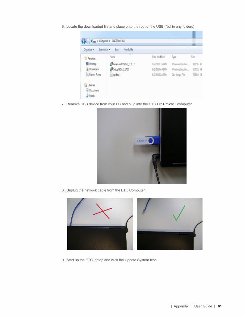
| Appendix | User Guide | 61
6. Locate the downloaded ile and place onto the root of the USB (Not in any folders)
7. Remove USB device from your PC and plug into the ETC Pro+/micro+ computer.
8. Unplug the network cable from the ETC Computer.
9. Start up the ETC laptop and click the Update System Icon.

62 | User Guide | Appendix |
10. Wait for the update screen to arrive.
11. Click Update (Update may last about an hour)
12. Reboot ETC after a successful update.
13. Plug in the network cable and the off-line update procedure is completed.

| Appendix | User Guide | 63
Wireless Ad-Hoc
NetworkUNI generates the vital signs information displayed on the virtual monitor PC. The information is transmitted through a wireless ad-hoc connection between the two computers in real time.
The wireless settings are conigured at the factory, so no additional coniguration is required. Please reference the troubleshooting information to resolve common connectivity issue before attempting to reconigure the network.
Use the “Create an ad-hoc Wireless network” tool to conigure the wireless ad-hoc link between the two computers. Then, conigure the connection between UNI and the Gaumard Monitors software.
UNI NETWORK CONFIGURATION
Complete the next steps using the “Controller - Create Ad-Hoc Wireless Network” tool built in to UNI software.
1. From the menu bar, go to Help > “Create ad-hoc Wireless Network”
The “Controller - Create Ad-hoc Wireless Network” window is displayed
2. Select the “Wireless Network Adapter”. If the wireless adapter is not listed, irst enable the adapter using the Windows® network menu and then return to this window.
3. Enter a wireless network name (case sensitive). Use the same wireless network name to conigure the Gaumard Monitors
PC. “GaumardNet” is the required name for Windows® 7 computers.
4. Set the “Controller IP”.
On each control PC and virtual monitor PC, enter the same values for the irst three IP ields and a set unique value for the last ield. The suggested address is for the Controller IP is 10.1.1.200
5. Click “Apply Wireless Network Settings” to save the settings.
6. Restart the computer.
GAUMARD MONITORS NETWORK
CONFIGURATION
After the UNI control computer is conigured, complete the next steps using the “Create an ad-hoc network tool” included in Gaumard Monitors software.
1. On the virtual monitor computer, click the Gaumard Monitors icon to start the vital signs software.
2. Click the V menu near the top left corner and select “Create Ad-Hoc Network”.
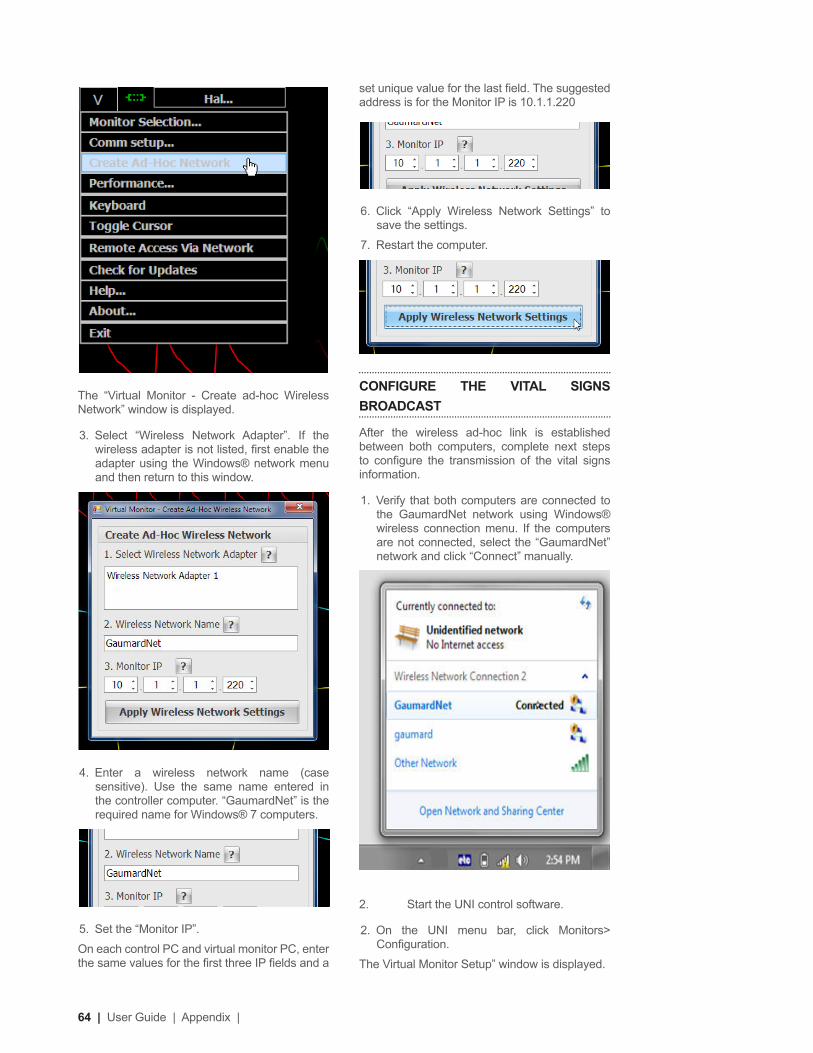
64 | User Guide | Appendix |
The “Virtual Monitor - Create ad-hoc Wireless Network” window is displayed.
3. Select “Wireless Network Adapter”. If the wireless adapter is not listed, irst enable the adapter using the Windows® network menu and then return to this window.
4. Enter a wireless network name (case sensitive). Use the same name entered in the controller computer. “GaumardNet” is the required name for Windows® 7 computers.
5. Set the “Monitor IP”.
On each control PC and virtual monitor PC, enter the same values for the irst three IP ields and a
set unique value for the last ield. The suggested address is for the Monitor IP is 10.1.1.220
6. Click “Apply Wireless Network Settings” to save the settings.
7. Restart the computer.
CONFIGURE THE VITAL SIGNS
BROADCAST
After the wireless ad-hoc link is established between both computers, complete next steps to conigure the transmission of the vital signs information.
1. Verify that both computers are connected to the GaumardNet network using Windows® wireless connection menu. If the computers are not connected, select the “GaumardNet” network and click “Connect” manually.
2. Start the UNI control software.
2. On the UNI menu bar, click Monitors> Coniguration.
The Virtual Monitor Setup” window is displayed.

| Appendix | User Guide | 65
3. Set the adapter to “Wireless network connection” and click “Connect” to begin transmitting the vital signs information. Write down the “controller IP” and “Port number”.
4. Start the Gaumard Monitors software on the virtual monitor PC.
5. Click the “V” menu near the top left corner, and then select “Comm Setup”.
The “TCP Comm Setup” window is displayed.
6. Enter the “Controller IP” and “Port number” displayed on the UNI “Virtual Monitor Setup” window.
7. Click “Connect” to accept the incoming connection.
Microphone Boost
for Streaming
AudioUse the instructions below to increase the streaming audio volume. The Headset must be connected to the tablet in order to adjust the microphone volume properties. In addition, adjust the recording control on the headset’s physical control to high.
1. Right click on the speaker icon located on the bottom right corner of the laptop’s taskbar.
2. The speaker menu is displayed. Click on the recording devices option.
3. The sound properties window and recording tab are displayed. Right-click the microphone option and select properties.
4. From the microphone properties sub menu, select the Levels tab. Use the microphone control to decrease and increase the recording volume. For an additional increase in recording volume, use the microphone boost control.
Microphone boost increases volume and saturation which can decrease overall clarity. For optimal clarity, adjust the microphone volume to 100 and the microphone boost to +10.
5. Click OK to save the changes to the volumes on the microphone properties menu.
6. Click OK to close the Sound properties window.
7. It might be necessary to re-adjust the microphone settings to accommodate environment noise.
Replacing Common
Consumables
IV Arm Vein
WARNING
Vein tubing contains latex which may cause allergic reactions. Users allergic or sensitive to latex should avoid contact. Discontinue use of this product and seek medical attention if an allergic reaction occurs.
To replace the vein used in the lower right arm, follow the instructions listed below:
GATHER THE FOLLOWING ITEMS:
• Replacement vein set
• Mineral oil
• Heat gun or blow dryer
• Hemostat
REPLACING THE IV VEINS
1. Attach the drainage tube to the drainage port on the lower arm of the simulator, and purge the system.
2. Gently heat the arm skin

66 | User Guide | Appendix |
3. Pull back the skin from the lower arm and remove it completely.
4. To replace the anterior veins of the arm, gently pull out the veins from each white connector as shown below.
5. Remove both black rings on the tubes and place them on the replacement veins
6. Insert the replacement veins to each white connector, and secure the veins with the black rings.
7. To replace the dorsal vein of the hand, gently pull out the vein from the white connectors.
8. Once removed, attach one end of the replacement vein to one of white connectors as shown below.
9. Feed this vein through the hole. You may use a hemostat to help you pull out the vein
10. Attach the other end of vein to the second white connector, and secure both ends of the vein with the black rings.
11. Heat the skin.
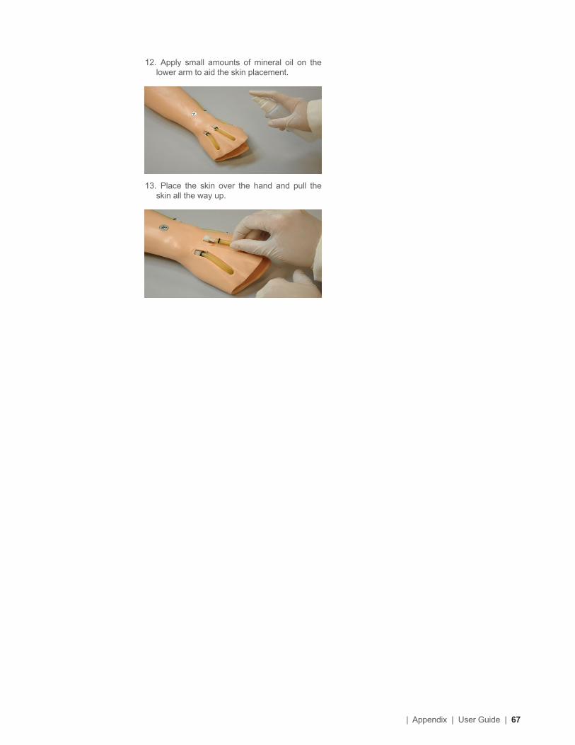
| Appendix | User Guide | 67
12. Apply small amounts of mineral oil on the lower arm to aid the skin placement.
13. Place the skin over the hand and pull the skin all the way up.

68 | User Guide | Appendix |
Warranty
EXCLUSIVE ONE-YEAR LIMITED WARRANTY
Gaumard warrants that if the accompanying Gaumard product proves to be defective in material or workmanship within one year from the date on which the product is shipped from Gaumard to the customer, Gaumard will, at Gaumard’s option, repair or replace the Gaumard product.
• This limited warranty covers all defects in material and workmanship in the Gaumard product, except:
• Damage resulting from accident, misuse, abuse, neglect, or unintended use of the Gaumard product;
• Damage resulting from failure to properly maintain the Gaumard product in accordance with Gaumard product instructions, including failure to property clean the Gaumard product; and
• Damage resulting from a repair or attempted repair of the Gaumard product by anyone other than Gaumard or a Gaumard representative.
This one-year limited warranty is the sole and exclusive warranty provided by Gaumard for the accompanying Gaumard product, and Gaumard hereby explicitly disclaims the implied warranties of merchantability, satisfactory quality, and itness for a particular purpose. Except for the limited obligations speciically set forth in this one-year limited warranty, Gaumard will not be liable for any direct, indirect, special, incidental, or consequential damages, whether based on contract, tort, or any other legal theory regardless of whether Gaumard has been advised of the possibilities of such damages. Some jurisdictions do not allow disclaimers of implied warranties or the exclusion or limitation of consequential damages, so the above disclaimers and exclusions may not apply and the irst purchaser may have other legal rights.
This limited warranty applies only to the irst purchaser of the product and is not transferable. Any subsequent purchasers or users of the product acquire the product “as is” and this limited warranty does not apply.
This limited warranty applies only to the products manufactured and produced by Gaumard. This limited warranty does not apply to any products provided along with the Gaumard product that are manufactured by third parties. For example, third-party products such as computers (desktop, laptop, tablet, or handheld) and monitors (standard or touch-screen) are not covered by this limited warranty. Gaumard does not provide any warranty, express or implied, with respect to any third-party products. Defects in third-party products are covered exclusively by the warranty, if any, provided by the third-party.
• Any waiver or amendment of this warranty must be in writing and signed by an oficer of Gaumard.
• In the event of a perceived defect in material or workmanship of the Gaumard product, the irst purchaser must:
• Contact Gaumard and request authorization to return the Gaumard product. Do NOT return the Gaumard product to Gaumard without prior authorization.
• Upon receiving authorization from Gaumard, send the Gaumard product along with copies of (1) the original bill of sale or receipt and (2) this limited warranty document to Gaumard at 14700 SW 136 Street, Miami, FL, 33196-5691 USA.
If the necessary repairs to the Gaumard product are covered by this limited warranty, then the irst purchaser will pay only the incidental expenses associated with the repair, including any shipping, handling, and related costs for sending the product to Gaumard and for sending the product back to the irst purchaser. However, if the repairs are not covered by this limited warranty, then the irst purchaser will be liable for all repair costs in addition to costs of shipping and handling.
Extended Warranty In addition to the standard one year of coverage, the following support plans are available: Two-Year Extension (covers second and third years)
Call for pricing (USA only)Tips on Creating Scenarios

Contact UsE-mail Technical Support: [email protected]
Before contacting Tech Support you must:
1. Have the simulator’s Serial Number
2. Be next to the simulator if troubleshooting is needed.
E-mail Sales and Customer Service: [email protected]
Phone: Toll-free in the USA: (800) 882-6655
Worldwide: 01 (305) 971-3790
Fax: (305) 667-6085
Post: Gaumard Scientiic
14700 SW 136 Street
Miami, FL 33196-5691
USA
Ofice hours: Monday-Friday, 8:30am - 4:30pm EST (GMT-5, -4 Summer Time)
General Information
Gaumard®, ZOE®, Michelle®, Mike®, PEDI®, Susie Simon®, Susie®, Simon® Code Blue®, SIMA Models®, SIMA GYN/AID®, Virtual Instruments®, Codemaker®, Code Blue®, NOELLE®, Simulation Made Easy™, HAL®, eCPRL™, Zack™, RITA™, Chloe™, Seatbelt Susie™, Krash Kids™, Premie™, UNI™, Omni®, SmartSkin™ are Trademarks of:
© Gaumard Scientiic Company, 2014All rights reserved.Gaumard®, NOELLE®, HAL® are trademarks of Gaumard Scientiic Company, Inc.Patented; Other Patents PendingAlways dispose of this product and its components in compliance with local laws and regulations.