trapezoidal vérins martinetes hubelemente mécaniques ... · there are different ways to transport...
TRANSCRIPT

Istruzioni perl’assemblaggio
Martinettimeccaniciad astatrapezia
Assemblyinstructions
Trapezoidal screw jacks
Notice d’assemblage
Vérinsmécaniques a vistrapezoidale
Instruccionespara el montaje
Martinetes mecánicos con husillo trapezoidal
Montageanleitung
Hubelemente mit trapezge-winde
Direttiva Europea06/42/CEAllegato VIver. 1.0
European Directive 06/42/EC Annex VIver. 1.0
Directive Européenne 06/42/CE Annexe VIver. 1.0
Directiva Europea 06/42/CE Anexo VIver. 1.0
Europäische Richtlinie 06/42/EGAnhang VIver. 1.0

London
Translation of the original instructions edited accordingto annex I - 1.7.4.1
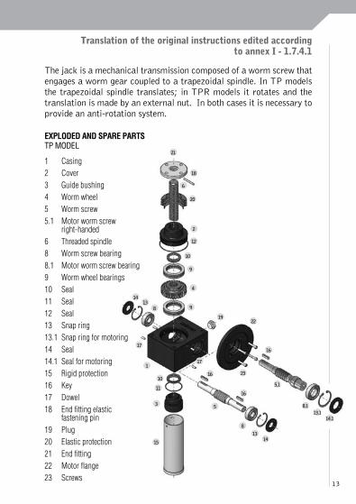
The jack is a mechanical transmission composed of a worm screw that engages a worm gear coupled to a trapezoidal spindle. In TP models the trapezoidal spindle translates; in TPR models it rotates and the translation is made by an external nut. In both cases it is necessary to provide an anti-rotation system.
21
18
6
20
2
12
10
9
4
9
19
171
10
11
3 5
16
16
16
22
23
5.1
8.113.1
14.1
8
1314
15
1413
8
17
13
EXPLODED AND SPARE PARTSTP MODEL
1 Casing2 Cover3 Guide bushing4 Worm wheel5 Worm screw5.1 Motor worm screw right-handed6 Threaded spindle8 Worm screw bearing8.1 Motor worm screw bearing9 Worm wheel bearings10 Seal11 Seal 12 Seal 13 Snap ring13.1 Snap ring for motoring14 Seal14.1 Seal for motoring15 Rigid protection16 Key17 Dowel18 End fitting elastic fastening pin19 Plug20 Elastic protection21 End fitting22 Motor flange23 Screws

14
7
6
20
2
12
10
9
4
18.1
9
18.1
1413
8
17
1
10
11
3
24
19
17
16
16
5
22
23
16
5.1
8.1
13.114.1
8
1314
EXPLODED AND SPARE PARTSTPR MODEL
1 Casing
2 Cover
3 Guide bushing
4 Worm wheel
5 Worm screw
5.1 Motor worm screw right handed
6 Threaded spindle
7 Lead nut
8 Worm screw bearing
8.1 Motor worm screw bearing
9 Worm wheel bearing
10 Seal
11 Seal
12 Seal
13 Snap ring
13.1 Snap ring for motoring
14 Seal
14.1 Seal for motoring
16 Key
17 Dowel
18.1 Worm wheel elastic fastening pin
19 Plug
20 Elastic protection
22 Motor flange
23 Screws
24 Seal
15
APPLICABLE ESSENTIAL SAfETy REQUIREMENTS ANNEx I
1.1.3 Materials and productsThe trapezoidal screw jacks are made of metallic materials (bronze, cast-iron, aluminum and steel) and polymeric gaskets. In the case that the supply includes electromechanical components, compliance to the ROHS regulation is ensured for these components.The whole range of TP-TPR models has long lasting internal grease lubrication; this lubricant does not report any R or S phrase on the safety sheet.Even if the screw jack tightness is ensured, occasional lubricant leakages from the gaskets could occur.Some accessories (PRO-CU-CS-CSU-SU-SUA-RG) may present endemic leakages. Refer to the general catalog for further information.
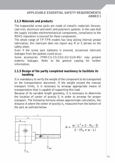
1.1.5 Design of the partly completed machinery to facilitate its handlingIt is mandatory to verify the weight of the component to be transported on the transportation document. If the weight exceed the manual transport limits, it is necessary to arrange appropriate means of transportation that is capable of supporting this load. Because of its variable length geometry, it is necessary to determine the location of center of gravity G in order to arrange for proper transport. The following formula allows approximate calculation, the distance A where the center of gravity is, measured from the bottom of the jack as outlined below.
A = w . L2 + 2 . Pm . D2 . (Pm + w . L)

16
w = spindle weight [kg/m] L = spindle total length [m]Pm = jack body weight [kg] A = center of gravity position [m]
183 204 306 407 559 7010 8010
Pm[kg] 1,8 5,9 10 18 34 56 62
W[kg/m] 1,6 2,2 5 9 18 28 37
A[m] 0,035 0,055 0,070 0,95 0,115 0,128 0,128
9010 10012 12014 14014 16016 20018 25022
Pm[kg] 110 180 180 550 550 2100 2100
W[kg/m] 56 56 81 110 140 220 350
A[m] 0,165 0,185 0,185 0,245 0,245 0,300 0,300
In the presence of asymmetrical engines or masses pay attention to the possible overturning movement.There are different ways to transport a trapezoidal screw jack before its incorporation in a machine:
a) Manual transport: avoid taking the screw jack by the worm screw projections, because an overturn can be triggered. In AR presence pay attention to sharp corners. Pay also attention to residual lubricants that can cause sliding. Pay attention to sharp corners (1.3.4).
b) Transport hung by eye-bolts: fasten the eye-bolts on the screw jack fastening holes only. Pay attention to swinging during the transport.
c) Transport hung by magnet: pay attention to swinging during the transport.

17
d) Transport hung by bands: pay attention to swinging during the transport. Pay attention if you fasten the bands on the worm screw projections or on lateral P pins, because an overturn can be triggered. Pay attention to the possible change in momentum due to the presence of eye-bolt terminals and/or PO.
e) Sustained transport: pay attention to residual lubricants on surfaces that can cause sliding, especially in acceleration and deceleration phases.
During the warehousing, the screw jacks must be protected so that dust or foreign bodies cannot be deposited. It is necessary to pay particular attention to the presence of corrosive or salty atmospheres. We also recommend:
a) periodically rotating the worm screw to ensure the appropriate lubrication of the internal parts and to avoid the drying out of the gaskets causing lubricant leakages.
b) lubricating and protecting the spindle, the worm screw and the unpainted components.
c) holding the spindle up if the storage is horizontal.
1.2.1 Safety and reliability of control systemsSome accessories (CSU-SUA-CR) have an electric proximity whose calibration is taken during the mounting. CT accessory has a thermal probe. Connecting the wires according to the electric scheme provided with the supply is mandatory.The eventual alarm signal either for the wear limit quota (CSU-SUA), for the non-rotation of the worm gear (CR) or for the reaching of the temperature limit, must be visible and understandable (paragraph 1.7.1.2).
1.2.3. StartingAs an irreversible transmission, the screw jacks can only be driven by worm screw rotation, which corresponds, respectively for TP and TPR models, to a translation of the spindle or the nut.It is necessary to take some precautions during the first screw jacks movements:

18
a) Lubricate the spindle and ensure the absence of foreign bodies on it.
b) Check the calibration of any limit switches, keeping in mind the inertia of the driven masses.
c) Take it gradually, if possible, to the operating conditions, in order to allow the breaking-in of the screw jacks.
d) Pay close attention to the overheating of the components, avoiding continuous maneuvers and allowing all the time necessary to reach the thermal balance with the environment after use. Remember that only one temperature peak may cause wear and deformations capable of threatening the useful life of the partly completed machinery.
1.2.4.3 Emergency stopFor TP models, BU and PRF accessories have an anti-withdrawal bush as emergency stop, preventing the spindle from coming out. In the case of impact between this bush and the screw jack body, replacement of the transmission is recommended, because the collision may have damaged some internal component.
1.3.2 Risk of break-up during operationThe screw jack, if properly sized as required in the general catalog (taking care to never exceed the indicated maximum load values), may fail during the operation due to a deterioration of its constituent components, both fixed and mobile.
The causes of damage may be different:
a) Deficiency or deterioration of the lubrication of the internal components: the grease used for the lubrication of the internal components is a long lasting one. In the presence of leakage (or in the case of full replacement, suggested every 5 years), it is necessary a top-off the lubricant, bringing quantity back to the factory values (in the table below).

19
183 204 306 407 559 7010 8010
Internal lubricant quantity
[kg]
0,06 0,1 0,3 0,6 1 1,4 1,4
9010 10012 12014 14014 16016 20018 25022
Internal lubricant quantity
[kg]
2,3 4 4 14 14 28 28
In the case of topping-off or replacement, it is necessary to use a lubricant having the characteristics listed in the catalog according to DIN 51502, in order to ensure the same performance capabilities. It is also necessary to verify the compatibility between basic oils and thickening agents, in order to avoid splitting of the grease.
b) Deficiency or deterioration of spindle lubrication: the user must lubricate the spindle and the operation must be repeated, depending of the type of work and environment, frequently so to ensure the presence of a clean lubricant layer between the surfaces in contact with each other. The use of adhesive and additive lubricants P or EP, according to the technical specifications listed in the catalog is mandatory. Because of the V-ring gasket nature (particular 10), the spindle lubricant may go inside the casing; for this reason it is necessary to verify the compatibility between the two lubricants, in order to avoid the splitting of the internal grease.
c) Failure due to the wear of subject components: the constituent components subject to friction suffer the effects of wear. Bronze parts (4 and 7) are the most vulnerable to wear and the scraped material often settles on the worm gear and spindle (5 and 6)altering the contact geometry. The failures of the bearings (8 and 9) cause the transmission to stop, while the wear of the gaskets (10 and 14) favors the leaks.

20
d) Lateral loads or misalignments: it is essential to ensure the orthogonality between the spindle and the casing support plate and to check the concentricity between the load and the spindle itself. The application of more screw jacks to the load movement requires further verification: it is necessary that the support points of the load, (terminals for TP models and the nuts for TPR models), be perfectly aligned, so that the load is divided evenly. If not, the misaligned screw jacks would act as contrast or brake. In the case of compression, the phenomena consequential to the peak load may trigger lateral loads and instability.
e) Asynchromism: if several screw jacks are connected through transmission shafts the verification of their perfect alignment, in order to avoid overloads on the worm screws is suggested.
The use of joints capable of absorbing alignment errors, without losing the torsion rigidity necessary to ensure the synchronization of the transmission is also recommended.
f) Corrosion: it is necessary to verify the corrosion resistance of the constituent components depending on the work environment.
1.3.3 Risks due to falling or ejected objectsIf appropriate measures are not taken, the mobile elements, spindle (6) and nut (7), respectively for TP and TPR models, can come off of the transmission fixed part.
1.3.4 Risks due to surfaces, edges or anglesThe screw jacks have sharp edges that, even if blunted, can present both blunt and sharp residual risks.
1.3.7 Risks related to moving partsSome constituent components are not in the casing; for this reason they can present residual risks regarding their movement. The following is a non-exhaustive list of moving parts.

21
TP MODELRotating parts: worm screw, CS, SU, SUA.Translating parts: spindle, BU, PRF, AR.
TPR MODELRotating parts: worm screw, spindleTranslating parts: nut, CS, CSU, SU, SUA, RG.
The following accessories provide protection from moving parts as written in paragraph 1.4.1: PR, PRO, CU, PE, PRA, PO.We recommend verifying the real transmission ratio on the descriptive tables in the general catalog in order to obtain the correct kinematics.
1.5.4 Errors of fittingRotation and translation directions are displayed on the casing in order to avoid mounting errors. However, it is recommended to check them before mounting. Unimec provides, as a standard, screw jacks with rotation and translation directions 1 and 2 (called “right”). If necessary, it is possible to provide the transmissions with a kinematic type 3 and 4 (called “left”).
Pay particular attention in the case that several screw jacks are assembled on the same transmission. In this case, verifying the section regarding assembly diagrams in the general catalog is recommended. Keep in mind that these diagrams are valid for directions of right rotation.
1 2 3 4

22
1.5.5 Extreme temperaturesBecause of its nature as an irreversible transmission, the screw jack tends to heat up quickly. Residual risks caused by hot surfaces remain during the operation and cooling stages.
1.5.8 NoiseBecause of its nature as a mechanical transmission, the screw jack emits noise during the operation. Proper lubrication tends to reduce the phenomenon, even if residual risks remain.
1.5.9 VibrationsBecause of its nature as a mechanical transmission, the screw jack, during operation, may be active source of vibration, especially in large structures and in presence of several transmission parts. It should be noted that, as for smaller sizes and in presence of insignificant loads, active vibrations impacting the screw jack may trigger a partial reversibility of the transmission.
1.6.1 Partly completed machinery maintenanceBecause of that which was mentioned in paragraph 1.3.2, in the standard use conditions (ambient temperature 20°C, working without shock, screw jack checked to equivalent load and power as reported on the general catalog), it is necessary to arrange periodic inspections at least once every month. During these inspections it is necessary to ensure the absence of lubricant leaks from the gaskets, the absence of foreign bodies on the spindle as well as its proper lubrication. If necessary, restore the proper quantities of lubricant on the spindle and inside the casing.
At least once a year it is necessary to check the transmission status more thoroughly: wear phenomena, grease splitting status, presence of scraped bronze parts on the spindle, full replacement of the lubricant, and replacement of critical components.
These inspections should be more frequent under more demanding conditions of use.

23
Maintenance operations must be made when the transmission is not in use and by qualified persons. If necessary, please check on the website for the nearest contact and call for assistance.
1.7.3 Marking of partly completed machineryEvery screw jack is marked with a metallic plate showing the Unimec name and logo, a contact reference, model, size, constructive form and the transmission serial number. With the latter, it is possible to trace every detail regarding this component life, from the supply issue to its delivery. Screw jacks, because of their partly completed nature, cannot be marked “CE”. Also, for this reason, they cannot be marked according to the ATEX regulations, even if, they can be considered “components suitable for the application in potentially explosive atmospheres”, after completing the related questionnaire and after the favorable opinion of the technical office.

60

61

62

7
6
20
2
12
10
9
4
18.1
9
18.1
1413
8
17
1
10
11
3
24
19
17
16
16
5
22
23
16
5.1
8.1
13.114.1
8
1314
ESPLOSI E RICAMBIMODELLO TPR
1 Carter2 Coperchio3 Bussola di guida4 Ruota elicoidale 5 Vite senza fine5.1 Vite senza fine dx motorizzata6 Asta filettata7 Chiocciola8 Cuscine t to de l l a v i t e senza fine8.1 Cuscinetto della vite senza fine motorizzata9 Cuscinetto della ruota elicoidale10 Anello di tenuta11 Anello di tenuta12 Anello di tenuta13 Seeger13.1 Seeger per motorizzazione14 Anello di tenuta14.1 Anello di tenuta per motorizzazione16 Chiavetta17 Grano18.1 Spina elastica ruota19 Tappo20 Protezione elastica22 Flangia motore23 Viti24 Tappo

Unimecvia del Lavoro 20 | 20040 Usmate-Velate (MB) | Italiatel. +39.039.6076900 | fax [email protected]
Unimec France29, Rue des Cayennes | Z. A. BoutriesBP 215 | 78702 Confl ans Cedex | Francetel. +33.1.39196099 | fax [email protected]
Unimec HispaniaC/Permanyer 34 | 08025 Sabadell (Barcelona) | Españatel. +34.93.1147067 | fax [email protected]
Unimec Trivenetovia della Tecnica 10 | 35035 Mestrino (Pd) | Italiatel. +39.049.9004977 | fax [email protected]
www.unimec.eu