transtector 1101-913 & 914 outdoor ppc …...... transfer switch contactor annunciation wiring...
TRANSCRIPT

REVISIONS
LTR DESCRIPTION ECN DATE APPROVED
A PRELIMINARY RELEASE DD2525 1/16/08
TRANSTECTOR 1101-913 & 914 OUTDOOR PPC AUTOMATIC TRANSFER
SWITCH CONTROLLER WITH TVSS 100 AMP & 200 AMP SERVICE 24 POSITION
LOAD CENTER 64”H X 30”W X 12”D
DRAWN
CBY
DATE
1/16/08
CHECKED
DPM
1/29/08 ENGRG APPD
DLR
2/4/08 TITLE
SPECIFICATION PPC-ATS 1101-913 & 1101-914 100AMP & 200AMP 24 POSITION
PROJ APPD
MLH
2/5/08 APPROVED
NOTICE:
THE INFORMATION AND DESIGN IN THIS DOCUMENT IS THE PROPERTY OF TRANSTECTOR SYSTEMS. ALL RIGHTS RESERVED.
DOCUMENT NUMBER
1400-648 REV
A CAGE
30992 PAGE 1 of 20
©2015 Transtector. All rights reserved

TABLE OF CONTENTS 1.0 GENERAL MODEL DESCRIPTION ........................................................... 3
1.1. Application: ............................................................................................. 4
1.2. Basic Theory of Operation: ..................................................................... 5
1.3. Power Transfer Switch Cabinet: ............................................................. 7
1.4. Doors and Locking Mechanism: ............................................................. 8
2.0 Inspecting Components and Unpacking Equipment ................................... 9
3.0 Mounting the PPC-ATS on an H-Frame or Wall ....................................... 10
3.1. External Ground ................................................................................... 10
3.2. Materials Needed ................................................................................. 10
3.3. Mounting the PPC-ATS ........................................................................ 10
4.0 Base Mounting the PPC-ATS ................................................................... 12
4.1. External Ground ................................................................................... 12
4.2. Mounting the PPC-ATS on Concrete Pad............................................. 12
4.3. Mounting the PPC-ATS on Structure .................................................... 13
5.0 Grounding ................................................................................................ 14
5.1. Service Entrance Applications .............................................................. 14
5.2. Non Service Entrance Applications ...................................................... 14
6.0 SPECIFICATIONS ................................................................................... 14
6.1. PHYSICAL: ........................................................................................... 14
6.2. POWER CENTER: ............................................................................... 14
7.0 ENVIRONMENTAL .................................................................................. 14
APPENDIX A: PROVIDED ACCESS ............................................................. 15
APPENDIX B: CABINET MOUNTING DIMENSIONS ................................... 16
APPENDIX C: WIRING SCHEMATIC DIAGRAM .......................................... 17
APPENDIX D: INTERFACE BOARD CONTROL PLATE .............................. 18
APPENDIX E: AC SUPPRESSOR REMOTE ANNUNCIATION WIRING DIAGRAM 19
APPENDIX F: TRANSFER SWITCH CONTACTOR ANNUNCIATION WIRING DIAGRAM 20

1400-648 Page 3 of 20 REV A
1.0 GENERAL MODEL DESCRIPTION
100 AMP & 200 AMP 24 POSITION OUTDOOR PPC CABINETS w/ ATS
The Transtector Power Protection Cabinet with Automatic Transfer Switch (PPC-ATS), Figure 1, provides a means of switching between utility power and generator power sources. Also included is a main breaker, a distribution panel, and transient voltage surge suppression. The enclosure is constructed of heavy gauge 5052-H32 aluminum with a powder coat paint finish. Dimensions of the cabinet are shown in Figure 2. The weight of the unit is approximately 150 lbs (68 Kg).
Figure 1: Transtector PPC-ATS

1400-648 Page 4 of 20 REV A
Figure 2: PPC-ATS Dimensions
WARNING . This product 120/240V power only.
1.1. Application:
The PPC-ATS is intended for use in critical applications that require continuous, protected AC power to a sensitive load. The unit has automatic voltage sensing and the ability to switch between utility and one backup generator. Typical applications may include remote locations where power quality and interruptions are frequent or applications where utility power may be shut down during peak demand hours.

1400-648 Page 5 of 20 REV A
1.2. Basic Theory of Operation:
The PPC-ATS is equipped with one 200 amp double pole double throw switch. This switch transfers between utility power and a backup generator source. The primary functions of the cabinet are controlled by the Transtector Design AC Power Interface with Embedded Controller which contains predefined parameters used in the basic operation, manual switching to generator, and generator load status functionality. Refer to appendix D illustration for features and indications. One set of “normally closed” Generator Start Contacts are provided for control of the generator source. In the event of utility power disruption, (either interruption or not meeting predefined power quality standard parameters) the controller will initiate a change over by engaging the appropriate contacts to start the backup generator source. An LED is located adjacent to the generator start contacts, and will illuminate to show that the controller is trying to demand the generator to start up. Once the backup source is within acceptable parameters, the switch will transfer the backup source to the load. Note that either the utility or generator power sources must be energized to provide AC power to illuminate this (and the other function) LED’s. If utility power is present for 5 minutes and is within acceptable parameters, the load will be transferred to utility power. The generator control contacts will remain closed for 5 additional minutes to provide a “cool down” time. Note that many generator manufacturers include additional internal generator cool down time features, which may extend the time from controller shut down to actual generator shut down. Control switch for automatic or generator source selection, customer monitoring relay contacts of the PPC-ATS status, and LED indicators are provided on the Transtector Design AC Power Interface with Embedded Controller. 1.2.1.-Auto Mode: When the Generator Source Select switch is turned to Auto, the system will be in auto mode. In auto mode, the system will perform all its duties as an open transition automatic transfer switch. If the utility voltage is present (and meets predefined quality requirements), the Utility Power Available LED will turn on; the ATS will close the utility contactor, and turn the corresponding ATS Status LED on. If the utility voltage fails, the ATS controller will send a generator start command to the generator, light up the associated LED at the generator start contact wire positions and the Power Available LED indicator will turn on to show the generator is running. The ATS contactor, after a short delay to allow the generator output voltage to stabilize, will then close to energize the load center and turn on the indicator light corresponding to the generator ATS Status. When the voltage from the utility is present again, the Power Available indicator will show this and the ATS controller will start the 5 minute utility mains settling timer. Once the timer is done, the ATS controller will switch the contactor to engage Utility power to the load center and the Utility ATS Status LED will turn on again. The
1400-648 Page 6 of 20 REV A
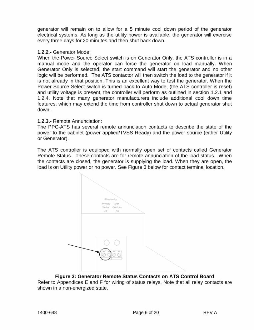
generator will remain on to allow for a 5 minute cool down period of the generator electrical systems. As long as the utility power is available, the generator will exercise every three days for 20 minutes and then shut back down. 1.2.2.- Generator Mode: When the Power Source Select switch is on Generator Only, the ATS controller is in a manual mode and the operator can force the generator on load manually. When Generator Only is selected, the start command will start the generator and no other logic will be performed. The ATS contactor will then switch the load to the generator if it is not already in that position. This is an excellent way to test the generator. When the Power Source Select switch is turned back to Auto Mode, (the ATS controller is reset) and utility voltage is present, the controller will perform as outlined in section 1.2.1 and 1.2.4. Note that many generator manufacturers include additional cool down time features, which may extend the time from controller shut down to actual generator shut down. 1.2.3.- Remote Annunciation: The PPC-ATS has several remote annunciation contacts to describe the state of the power to the cabinet (power applied/TVSS Ready) and the power source (either Utility or Generator). The ATS controller is equipped with normally open set of contacts called Generator Remote Status. These contacts are for remote annunciation of the load status. When the contacts are closed, the generator is supplying the load. When they are open, the load is on Utility power or no power. See Figure 3 below for contact terminal location.
Figure 3: Generator Remote Status Contacts on ATS Control Board Refer to Appendices E and F for wiring of status relays. Note that all relay contacts are shown in a non-energized state.

1400-648 Page 7 of 20 REV A
Figure E1 shows the relay contact positions to monitor either primary SASD or backup MOV suppressor modules. The wiring may be connected in any combination in series/parallel to achieve alarm on closure or open function. Figure F1 illustrates the locations of the switch terminals on each of the transfer switch contactor frames and diagram F2 provides a suggested interconnect circuit that can be used to provide a remote annunciation of generator failure/total site power failure/TVSS failure condition. 1.2.4.- Reset Button: The Reset Button resets the ATS controller. If the Reset Button is pressed or the Power Source Select switch is turned to Auto, the generator start contacts are closed (Generator Start LED lights up) and the generator should start up or continue to run. After a 5 minute generator exercise, the ATS will perform as outlined in section 1.2.1 along with a 5 minute cool down if the generator is not connected to the load. If the Power Source Select switch is turned to Generator Only and the Reset Button is pressed, the generator will continue to run. It is a good idea to reset the controller after any change of generator or for any practical testing purposes. Note: If ATS controller seems to not work as outlined, press the reset button to reset the ATS controller.
1.3. Power Transfer Switch Cabinet:
The PPC-ATS includes a load center that distributes electrical power and has 24 single-pole breaker positions. The specific features of the Power Transfer Switch include:
QOM1 100 amp or QOM2 200 amp Main Integral breaker
GE/Zenith Automatic Transfer Switch
Transtector Design AC Power Interface Transfer Switch Controller
24 Position Square D, Type QO load center
Transtector AC surge suppressor (uses 2 load center position)
20A breaker to TVSS
Neutral Distribution Block and Ground Bus Bar Connections
Optional 66-pin punch down block for I/O interconnection

1400-648 Page 8 of 20 REV A
Figure 4: Features of the PPC-ATS
1.4. Doors and Locking Mechanism:
The PPC-ATS is equipped with a 3 point latching system and a pad lockable handle. The cabinet is also equipped with a 135º wind stop to secure the door in an open position.
HINGED DEADFRONT .125” 5052-H32 ALUMINUM POWDER COAT FINISH TYPE 3R OUTDOOR ENCLOSURE
TRANSTECTOR AC SURGE SUPPRESSOR
CONTROLLER
QOM1 100 AMP OR QOM2 200 AMP MAIN INTEGRAL BREAKER
SQUARE D, TYPE QO LOAD CENTER
GE/ZENITH AUTOMATIC TRANSFER SWITCH
ILSCO NEUTRAL DISTRIBUTION BLOCK
WIND STOP

1400-648 Page 9 of 20 REV A
2.0 Inspecting Components and Unpacking Equipment Step 1: When the component arrives, visually inspect for damage. IMPORTANT: If the packaging appears to be damaged, do not accept the equipment from the shipper, as interior damage may have occurred.
Step 2: Unpack the cabinet, and dispose of all packaging according to local practices. Step 3: Locate the accessory kit, which is shipped in a cardboard box inside the
cabinet. Step 4: Verify that the accessory kits for the PPC-240V ATS contains all of the accessory parts, as listed in Table A.
TABLE A - Hardware Shipped with the PPC-240V ATS Cabinet Qty Description
1 Pad Gasket (see Figure 6) - Used for mounting cabinet on a concrete pad
Mounting Hardware Kit (shipped in plastic bag inside cabinet)
4 Hex Head Screws, ½”-13 x 1½”, PLT
6 Flat Washers, ½” I.D., 1 1/4” O.D.
4 Split Lock Washers, ½”, PLT
4 Hex Nuts, ½-13, PLT
4 U-Bolts, ¼”-20 ZN PLT STL
4 Hex Nuts,1/4”-20 (supplied with bolts)
Installation Kit and Instructions
1 Product Specification (this document)
1 #4 AWG Green bonding jumper wire
1 Warranty card

1400-648 Page 10 of 20 REV A
3.0 Mounting the PPC-ATS on an H-Frame or Wall To mount the PPC-ATS on an H-Frame, wall, or poles, use the procedure in this section as a general guide. Use hardware provided or your own approved hardware. Refer to Figure 5 for mounting hole pattern.
3.1. External Ground
IMPORTANT . A grounding system must be installed per NEC codes and local practices prior to PPC-ATS cabinet installation (See Section 5).
3.2. Materials Needed
To mount the PPC-ATS, you will need the following:
Wall Anchors or Materials for an H-frame
Four 3/8-inch (1 cm) mounting bolts and Six Sealing Washers (use supplied hardware or approved alternative)
Lifting equipment rated for 150 pounds (68 kg).
3.3. Mounting the PPC-ATS
Perform the following steps to mount the enclosure.
DANGER . When the cabinet is not attached to the pad and the door is open, it is extremely prone to tipping over forward.
Step 1: Construct and mount the H-Frame per local practices, or install appropriate wall anchors. Step 2: Remove the four knock-outs from the back of the cabinet. Step 3: Use appropriate lifting equipment to raise the cabinet into its mounting position and keep it supported. Step 4: Install one sealing washer on outside of cabinet and one on inside of cabinet at each of the four mounting locations (Figure 6). Tighten bolts securely.

1400-648 Page 11 of 20 REV A
Figure 5: Holes for Mounting PPC-240V ATS on H-Frame, Wall or Pole
CABINET (OUTSIDE)
SEALING WASHER
BOLT

1400-648 Page 12 of 20 REV A
Figure 6: Bolting Cabinet to an H-Frame or Wall
DANGER . The cabinet weighs approximately 150 lbs (68Kg). Make sure appropriate measures are taken to safely move the cabinet. Make sure that the cabinet is supported by the lifting equipment during installation.
4.0 Base Mounting the PPC-ATS To mount the PPC-ATS on a pad or structure, use the procedure in this section as a general guide. Use hardware provided or your own approved hardware. Refer to Figure 7 for mounting hole pattern.
Figure 7: Base Mounting Hole Pattern
4.1. External Ground
IMPORTANT . A grounding system must be installed per NEC codes and local practices prior to PPC-DATS cabinet installation (See Section 5).
4.2. Mounting the PPC-ATS on Concrete Pad
To mount the PPC-ATS on a concrete pad, use the procedure in this section as a general guide. Use hardware provided or your own approved hardware. Attach adhesive backed gasket (Figure 8) to cabinet.
1400-648 Page 13 of 20 REV A
4.3. Mounting the PPC-ATS on Structure
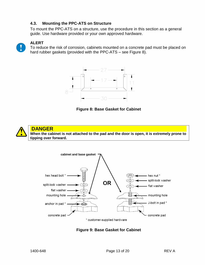
To mount the PPC-ATS on a structure, use the procedure in this section as a general guide. Use hardware provided or your own approved hardware. ALERT To reduce the risk of corrosion, cabinets mounted on a concrete pad must be placed on hard rubber gaskets (provided with the PPC-ATS – see Figure 8).
Figure 8: Base Gasket for Cabinet
DANGER . When the cabinet is not attached to the pad and the door is open, it is extremely prone to tipping over forward.
Figure 9: Base Gasket for Cabinet
cabinet and base gasket

1400-648 Page 14 of 20 REV A
5.0 Grounding
5.1. Service Entrance Applications
This cabinet is suitable for service entrance applications. A green 4AWG main bonding jumper is provided to bond the neutral and AC ground bar. Ground per NEC and local code practices.
5.2. Non Service Entrance Applications
Ground per NEC and local code practices.
5.3. Punch Down Block Grounding
Connect one end of Punch Down Block ground wire to the ground bar located on the left-hand side of the load center.
6.0 SPECIFICATIONS
6.1. PHYSICAL:
6.1.1. Cabinet Type ...................................................................... UL 50, NEMA Type 3R 6.1.2. Cabinet Material ........................................................ .. .080” 5052-H32 Aluminum 6.1.3. Wire Conduit Knockouts
Sides ........................... 3 per Side @n 2½” Conduit Trade Size (n2.97” Actual)
Bottom ....................................... 4@n 2½” Conduit Trade Size (n2.97” Actual)
6.1.4. Outer Cabinet Dimensions ............................................................. 64” X 30” X 12” 6.1.5. Mounting Holes (Bottom)...........................................................................4@n.44”
Mounting Hardware/Gasket ................................................................. Included 6.1.6. Weight .................................................................... Approximately 150 Lbs (68 Kg)
6.2. POWER CENTER:
6.2.1. Service ................................................. 120/240V, 1 Phase, 100 Amp or 200 Amp 6.2.2. Generator & Utility Breaker .................. Square D, Q Frame, 100 Amp or 200 Amp 6.2.3. Automatic Transfer Switch ..................................................... GE/Zenith, 200 Amp 6.2.4. Load Center ...............................100 Amp or 200 Amp, 24 Position Square D, QO 6.2.5. QO Style Branch Breakers ......................................................................................
(1) 20A Dual Pole (TVSS) .................................................................... Included 6.2.6. Suppression ......................... 120/240V Transtector MCP120TA-20M Suppression Primary Technology ................. Silicon Avalanche Suppressor Diodes (SASD) Secondary Technology ....................................... Metal Oxide Varistors (MOV)
7.0 ENVIRONMENTAL 7.1. Operating Temperature ................................................ -40°F(-40°C) to 167°F(75°C) 7.2. Storage Temperature ................................................... -40°F(-40°C) to 167°F(75°C) 7.3. Relative Humidity .................................................................. 100% Non-condensing

1400-648 Page 15 of 20 REV A
APPENDIX A: PROVIDED ACCESS

1400-648 Page 16 of 20 REV A
APPENDIX B: CABINET MOUNTING DIMENSIONS

1400-648 Page 17 of 20 REV A
APPENDIX C: WIRING SCHEMATIC DIAGRAM
CODE DESCRIPTION STATUS
BL
R
BU
W
G
BLACK
RED
BLUE
WHITE
GREEN
HOT
HOT
HOT
NEUTRAL
GROUND
(Unless Otherwise Noted)

1400-648 Page 18 of 20 REV A
APPENDIX D: INTERFACE BOARD CONTROL PLATE

1400-648 Page 19 of 20 REV A
APPENDIX E: AC SUPPRESSOR REMOTE ANNUNCIATION WIRING DIAGRAM
Figure E1: Individual Phase Protection Relay Alarm Wiring
Figure E2: Normally Open Relay Alarm Wiring
Figure E3: Normally Closed Relay Alarm Wiring (Note: Contacts are shown in a non-energized state.)
NC COMNO NC COMNO
NC COMNO NC COMNO
L1 L2
NC COMNO NC COMNO

1400-648 Page 20 of 20 REV A
APPENDIX F: TRANSFER SWITCH CONTACTOR ANNUNCIATION WIRING DIAGRAM
Figure F1: Switch Positions and Contacts
Figure F2: Suggested Generator Failure Alarm Circuit
BOTTOM 2 LEADS CLOSED = ON UTILITY POWER
BOTTOM 2 LEADS CLOSED = ON GENERATOR POWER ATS
N.O. N.C.
CLOSED = ON GENERATOR POWER
ATS CONTACTOR ANNUNCIATION
MCP SUPPRESSOR ANNUNCIATION
OPENED =SITE FAILURE