transporting data on the orbital angular momentum of light · leslie a. rusch canada research chair...
TRANSCRIPT

Leslie A. RuschCanada Research ChairCommunications Systems Enabling the Cloud
Transporting Data on the Orbital Angular Momentum
of Light

FOR FURTHER READING …
2

Outline
Motivation – overcoming the Shannon limit
Space Division Multiplexing systems
Fibers for SDM• Background on fibers• Eigenmodes & Few mode fibers
Linearly polarized (LP) modes solution• Multiple input, multiple output (MIMO) processing
Orbital angular momentum modes (OAM) solution• OAM fibers – why we like them & how we design them• OAM at UL• OAM transmission experiments
Conclusion
3

Squeezing Shannon
Coaxial cable to fiber optics• Increased distance & bandwidth

Squeezing Shannon
Coaxial cable to fiber optics• Increased distance & bandwidth
Fast electronics
A. Erik, et al., "Roadmap of optical communications," Journal of Optics, vol. 18, p. 063002, 2016.

Squeezing Shannon
Coaxial cable to fiber optics• Increased distance & bandwidth
Fast electronics
Wavelength Multiplexing
A. Erik, et al., "Roadmap of optical communications," Journal of Optics, vol. 18, p. 063002, 2016.
Squeezing Shannon
Coaxial cable to fiber optics• Increased distance & bandwidth
Fast electronics
Wavelength Multiplexing
Advanced modulation• polarization and I/Q
A. Erik, et al., "Roadmap of optical communications," Journal of Optics, vol. 18, p. 063002, 2016.

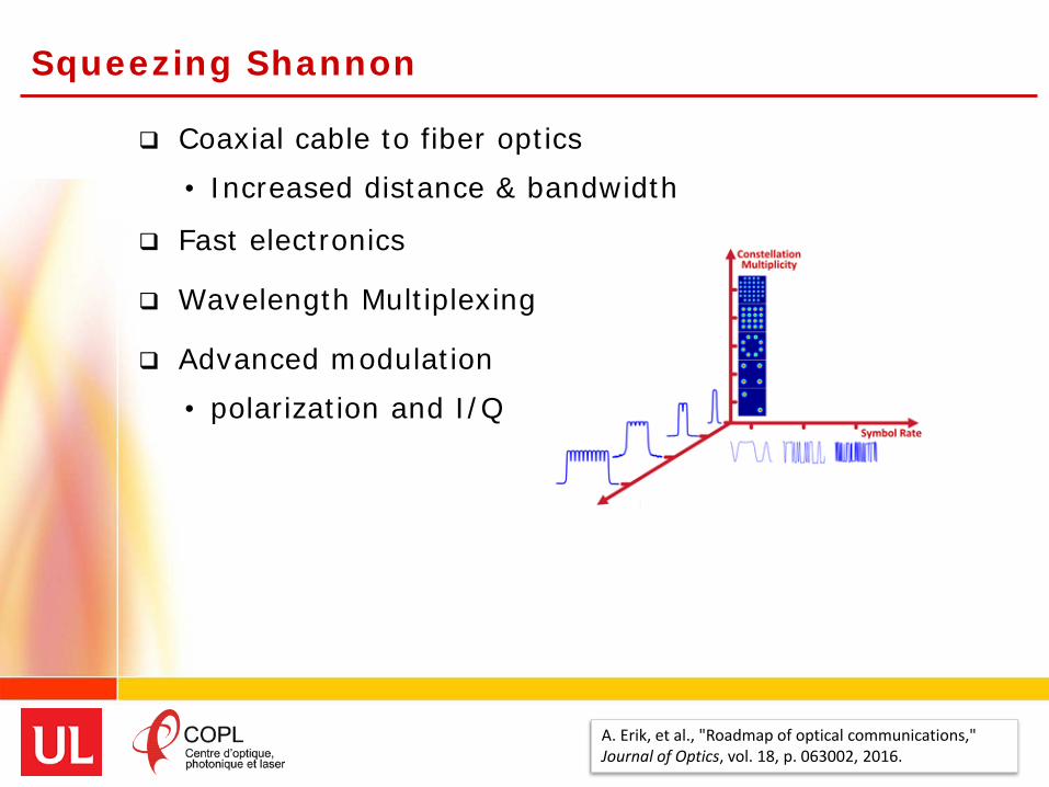
Squeezing Shannon
Coaxial cable to fiber optics• Increased distance & bandwidth
Fast electronics
Wavelength Multiplexing
Advanced modulation• polarization and I/Q
A. Erik, et al., "Roadmap of optical communications," Journal of Optics, vol. 18, p. 063002, 2016.
capa
city
Nonlinear Effects
Optical fibers are pretty thin …• 8 micron cores• Many wavelengths means high power
• Megawatts per square centimeter• Nonlinear effects
Sending more power makes performance worse• Not part of Shannon’s limit
9A. D. Ellis, et al., "Performance limits in optical communications due to fiber nonlinearity," Advances in Optics and Photonics, vol. 9, pp. 429-503, 2017/09/30.

Nonlinear Effects
Optical fibers are pretty thin …• 8 micron cores• Many wavelengths means high power
• Megawatts per square centimeter• Nonlinear effects
Sending more power makes performance worse• Not part of Shannon’s limit
10A. D. Ellis, et al., "Performance limits in optical communications due to fiber nonlinearity," Advances in Optics and Photonics, vol. 9, pp. 429-503, 2017/09/30.

Bandwidth growth and demand
11Winzer, P.J., "Spatial Multiplexing in Fiber Optics: The 10X Scaling of Metro/Core Capacities," Bell Labs Tech. J. , vol.19, pp.22-30, 2014

Bandwidth growth and demand
12
Global IP Forcast
Winzer, P.J., "Spatial Multiplexing in Fiber Optics: The 10X Scaling of Metro/Core Capacities," Bell Labs Tech. J. , vol.19, pp.22-30, 2014

Next wave of capacity increase
D. J. Richardson, J. M. Fini, and L. E. Nelson, "Space-division multiplexing in optical fibres," Nature Photonics, vol. 7, p. 354, 04/29/online.

Next wave of capacity increase
D. J. Richardson, J. M. Fini, and L. E. Nelson, "Space-division multiplexing in optical fibres," Nature Photonics, vol. 7, p. 354, 04/29/online.

Next wave of capacity increase
D. J. Richardson, J. M. Fini, and L. E. Nelson, "Space-division multiplexing in optical fibres," Nature Photonics, vol. 7, p. 354, 04/29/online.

Next wave of capacity increase
D. J. Richardson, J. M. Fini, and L. E. Nelson, "Space-division multiplexing in optical fibres," Nature Photonics, vol. 7, p. 354, 04/29/online.

Next wave of capacity increase
D. J. Richardson, J. M. Fini, and L. E. Nelson, "Space-division multiplexing in optical fibres," Nature Photonics, vol. 7, p. 354, 04/29/online.
space division multiplexing

Outline
Motivation – overcoming the Shannon limit
Space Division Multiplexing systems
Fibers for SDM• Background on fibers• Eigenmodes & Few mode fibers
Linearly polarized (LP) modes solution• Multiple input, multiple output (MIMO) processing
Orbital angular momentum modes (OAM) solution• OAM fibers – why we like them & how we design them• OAM at UL• OAM transmission experiments
Conclusion
18
Fiber bundles ?
Instead of electronic regeneration
Use parallel fiber systems
19

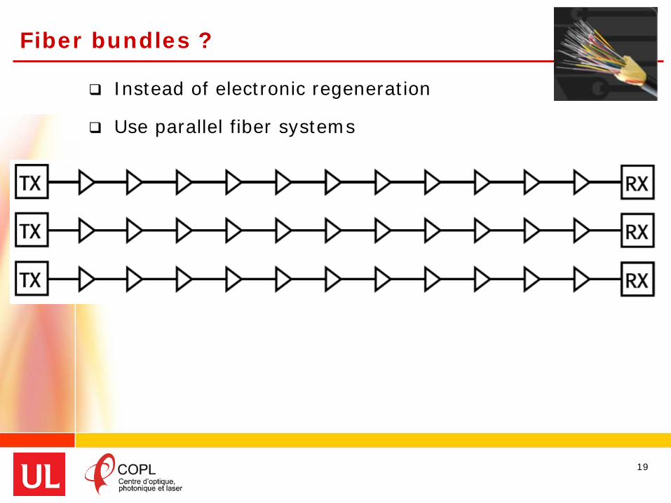
Fiber bundles ?
Instead of electronic regeneration
Use parallel fiber systems
20
Increased capacity, but• not greener• not cheaper
Integration drives down price per bit

Fiber bundles vs. fiber w/multiple channels
21

Fiber bundles vs. fiber w/multiple channels
Requirements• Fiber with multiple channels
22

Fiber bundles vs. fiber w/multiple channels
Requirements• Fiber with multiple channels• Integrate transceivers to higher capacity
23

Fiber bundles vs. fiber w/multiple channels
Requirements• Fiber with multiple channels• Integrate transceivers to higher capacity• Amplifiers
24

Fiber bundles vs. fiber w/multiple channels
Requirements• Fiber with multiple channels• Integrate transceivers to higher capacity• Amplifiers• Switches
25

Fiber bundles vs. fiber w/multiple channels
Requirements• Fiber with multiple channels• Integrate transceivers to higher capacity• Amplifiers• Switches
SDM offers • higher capacity • path to lower cost and power per bit
26

Spatial Multiplexing in New Fibers
a single core, a single mode56 Gbaud, 80 λs, DP-16QAM
27

Spatial Multiplexing in New Fibers
a single core, a single mode
multiple cores, each a single mode
28

Spatial Multiplexing in New Fibers
a single core, a single mode
a single core, multiple modes
multiple cores, each a single mode
29

Spatial Multiplexing in New Fibers
a single core, a single mode
a single core, multiple modes
multiple cores, each a single mode
ring core fiber
30

Spatial Multiplexing in New Fibers
a single core, a single mode
a single core, multiple modes
multiple cores, each a single mode
and eventually ….multiple cores, multiple modes
ring core fiber
31

Spatial Multiplexing in New Fibers
a single core, multiple modes
32
What kind of fiber can support the most modes?

Spatial Multiplexing in New Fibers
a single core, multiple modes
33
What kind of fiber can support the most modes?
What kind of modes?

Outline
Motivation – overcoming the Shannon limit
Space Division Multiplexing systems
Fibers for SDM• Background on fibers• Eigenmodes & Few mode fibers
Linearly polarized (LP) modes solution• Multiple input, multiple output (MIMO) processing
Orbital angular momentum modes (OAM) solution• OAM fibers – why we like them & how we design them• OAM at UL• OAM transmission experiments
Conclusion
34

Single mode vs. multimode
Fibers used to come in two types…• Small core (single mode)• Large core (multimode)
35
high performance, long distanceeasy to couple, cheap

Spatial division multiplexing
A new kind of fiber• Larger distances & bit rate of SMF• Avoid the modal dispersion of MMF• Modes as independent, separate channels
Need to control the modal interactions• Play with dimensions to limit the number of modes • Few mode fiber – not hundreds, not thousands
36

Few mode fibers
Modes in fibers: solutions of Maxwell's equations
Eigenmodes• Building blocks of derivative modes• Some solutions of Maxwell’s equation “flock” together
• mode groups that are interrelated and that interact
All depends on physical parameters of the fiber
37

SINGLE-MODE OPTICAL FIBER (SMF)
Even in single mode fiber – two polarizations
Gaussian shaped intensity profile
38

SINGLE-MODE OPTICAL FIBER (SMF)
Even in single mode fiber – two polarizations
Gaussian shaped intensity profile
39
arrows are polarization

Few-mode-fiber (FMF)
40
Six spatial and polarization modes to place information.
FEW-MODE
8 micron core

Few-mode-fiber (FMF)
41
Six spatial and polarization modes to place information.
Eigenmodes
FEW-MODE
8 micron core

Few mode fibers
Modes in fibers
Eigenmodes• Building blocks of derivative modes• Some solutions of Maxwell’s equation “flock” together
• mode groups that are interrelated and that interact
All depends on physical parameters of the fiber
Typical fibers have solutions called scalar modes• Solution of a simplified version of Maxwell’s equation• Called the “weakly guiding” solution
42
Refractive index of cladding ≈Refractive index of core
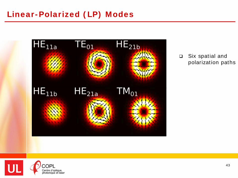
Linear-Polarized (LP) Modes
43
Scalar approximation to vector modes
Six spatial and polarization paths
Boxes indicate near-degenerate modes – expect strong coupling

Linear-Polarized (LP) Modes Scalar
approximation to vector modes
Six spatial and polarization paths
Boxes indicate near-degenerate modes – expect strong coupling
44

Linear-Polarized (LP) Modes Scalar
approximation to vector modes
Six spatial and polarization paths
Boxes indicate near-degenerate modes – expect strong coupling
45
LP01 LP11a LP11b

Linear-Polarized (LP) Modes Scalar
approximation to vector modes
Six spatial and polarization paths
Boxes indicate near-degenerate modes – expect strong coupling
46
Y-pol
LP01 LP11a LP11b
X-pol

Outline
Motivation – overcoming the Shannon limit
Space Division Multiplexing systems
Fibers for SDM• Background on fibers• Eigenmodes & Few mode fibers
Linearly polarized (LP) modes solution• Multiple input, multiple output (MIMO) processing
Orbital angular momentum modes (OAM) solution• OAM fibers – why we like them & how we design them• OAM at UL• OAM transmission experiments
Conclusion
47

LP modes or scalar modes
Studied for a long time
Intensity profiles of light for each mode
Degenerate modes … • Same propagation speed in the fiber• Similar geometry to intensity profiles
48

LP modes or scalar modes
LP for Spatial division multiplexing
Modal interactions mix transmitted signals
Digital signal processing at RX can undo this• Multiple input Multiple output (MIMO) processing
50
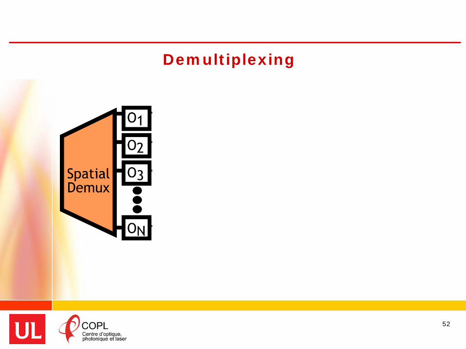
Electronic MIMO Demultiplexing
52

Electronic MIMO Demultiplexing
53
I1 = h11O1 + h12O2 + h13O3 + h14O4 + … + h1NON

Electronic MIMO Demultiplexing
Need the complex filter (time varying amplitudes/phases) for each mode output
54
I1 = h11O1 + h12O2 + h13O3 + h14O4 + … + h1NON

Electronic MIMO Demultiplexing
Number of filters scales with the square of number of modes
55
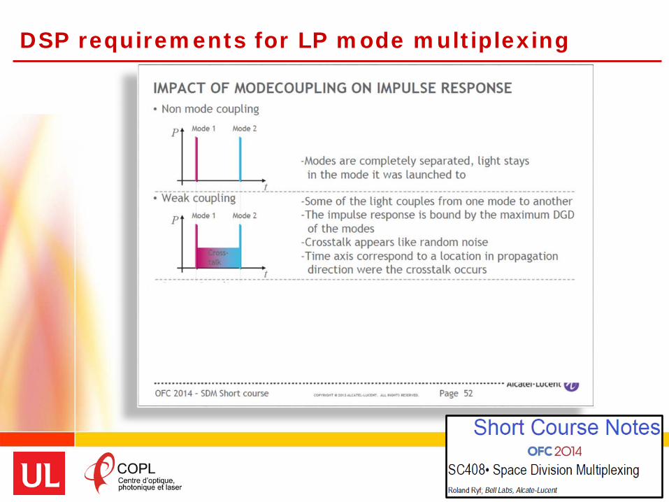
DSP requirements for LP mode multiplexing
57

DSP requirements for LP mode multiplexing
58

DSP requirements for LP mode multiplexing
59

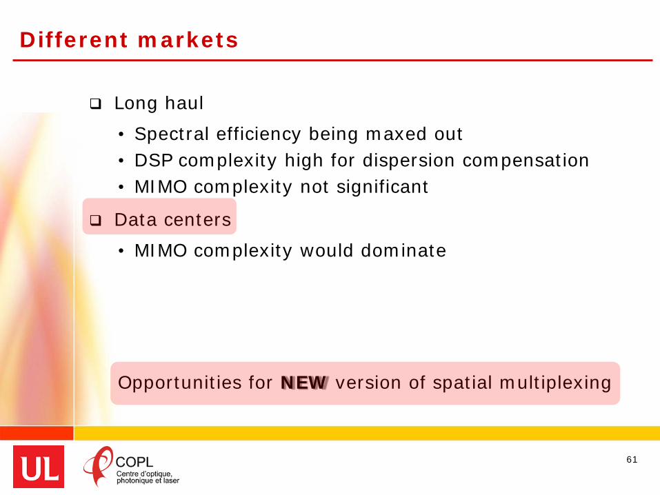
Different markets
Long haul• Spectral efficiency being maxed out• DSP complexity high for dispersion compensation• MIMO complexity not significant
Data centers• MIMO complexity would dominate
60
Different markets
Long haul• Spectral efficiency being maxed out• DSP complexity high for dispersion compensation• MIMO complexity not significant
Data centers• MIMO complexity would dominate
Opportunities for NEW version of spatial multiplexing
61

Outline
Motivation – overcoming the Shannon limit
Space Division Multiplexing systems
Fibers for SDM• Background on fibers• Eigenmodes & Few mode fibers
Linearly polarized (LP) modes solution• Multiple input, multiple output (MIMO) processing
Orbital angular momentum modes (OAM) solution• OAM fibers – why we like them & how we design them• OAM at UL• OAM transmission experiments
Conclusion
62

LP vs. OAM
Linearly polarized modes (LP)
• Well known & studied• First solution for SDM• Perturbations cause coupling
Orbital angular momentum modes (OAM)
• Recent subject of research• New solution for SDM• Robust to perturbations
63

Eigenmodes of a fiber
64

Linearly polarized (LP) Modes
LP11x LP11yLP01
65
Linear combination of fiber eigenmodes
LP21

Linearly polarized (LP) Modes
HE11 EH11 + HE31TE01 + HE21
LP11x
TM01 + HE21
LP11yLP01
66
Linear combination of fiber eigenmodes
LP21

Linearly polarized (LP) Modes
HE11 EH11 + HE31TE01 + HE21
LP11x
TM01 + HE21
LP11yLP01
67
Linear combination of fiber eigenmodes
LP21
crosstalk

Linearly polarized (LP) Modes
HE11
β1 β2 , β3 β5, β6
EH11 + HE31TE01 + HE21
LP11x
TM01 + HE21
β4 , β3
LP11yLP01
68
Different eigenmodes travel at different speeds
LP21

Linearly polarized (LP) Modes
HE11
β1 β2 , β3 β5, β6
EH11 + HE31TE01 + HE21
LP11x
TM01 + HE21
β4 , β3
LP11yLP01
69
Different eigenmodes travel at different speeds
LP21
modal birefringence & crosstalk

Linearly polarized (LP) Modes
HE11
β1 β2 , β3 β5, β6
EH11 + HE31
LP11x
TM01 + HE21
β4 , β3
LP11yLP01
OAM(1)OAM(0) OAM(-2) OAM(+2)
70
Eigenmodes combined differently for OAM …
LP21
TE01 + HE21

OAM Modes
HE11
β1 β3 β6
LP01
OAM(1)OAM(0) OAM(-2) OAM(+2)
71
Eigenmodes combined differently for OAM …
𝐇𝐇𝐇𝐇𝟐𝟐𝟐𝟐𝐞𝐞𝐞𝐞𝐞𝐞𝐞𝐞 + 𝐣𝐣𝐇𝐇𝐇𝐇𝟐𝟐𝟐𝟐𝐨𝐨𝐨𝐨𝐨𝐨 𝐇𝐇𝐇𝐇𝟐𝟐𝟐𝟐𝐞𝐞𝐞𝐞𝐞𝐞𝐞𝐞 + 𝐣𝐣𝐇𝐇𝐇𝐇𝟐𝟐𝟐𝟐
𝐨𝐨𝐨𝐨𝐨𝐨 𝐇𝐇𝐇𝐇𝟑𝟑𝟐𝟐𝐞𝐞𝐞𝐞𝐞𝐞𝐞𝐞 + 𝐣𝐣𝐇𝐇𝐇𝐇𝟑𝟑𝟐𝟐𝐨𝐨𝐨𝐨𝐨𝐨
β5
OAM0 OAM1 OAM-2 OAM2
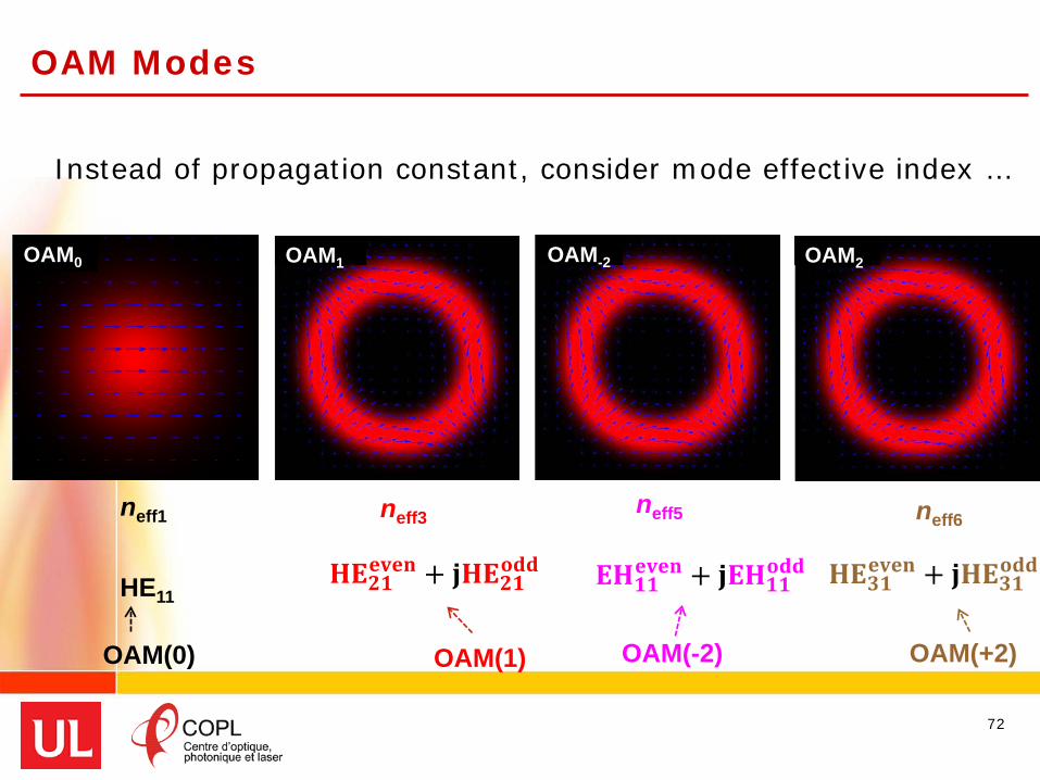
OAM Modes
neff1 neff3 neff6
LP11x LP11yLP01
OAM(1) OAM(-2) OAM(+2)
72
Instead of propagation constant, consider mode effective index …
LP21
𝐇𝐇𝐇𝐇𝟐𝟐𝟐𝟐𝐞𝐞𝐞𝐞𝐞𝐞𝐞𝐞 + 𝐣𝐣𝐇𝐇𝐇𝐇𝟐𝟐𝟐𝟐
𝐨𝐨𝐨𝐨𝐨𝐨 𝐇𝐇𝐇𝐇𝟑𝟑𝟐𝟐𝐞𝐞𝐞𝐞𝐞𝐞𝐞𝐞 + 𝐣𝐣𝐇𝐇𝐇𝐇𝟑𝟑𝟐𝟐𝐨𝐨𝐨𝐨𝐨𝐨
neff5
𝐇𝐇𝐇𝐇𝟐𝟐𝟐𝟐𝐞𝐞𝐞𝐞𝐞𝐞𝐞𝐞 + 𝐣𝐣𝐇𝐇𝐇𝐇𝟐𝟐𝟐𝟐𝐨𝐨𝐨𝐨𝐨𝐨
OAM0 OAM1 OAM-2 OAM2
HE11
OAM(0)
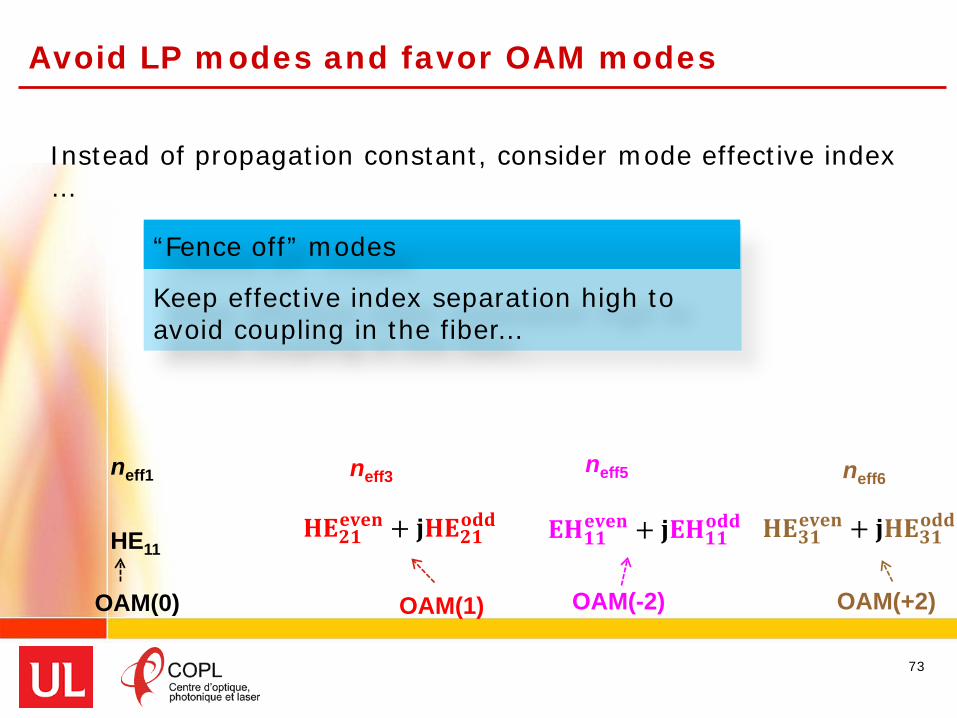
Avoid LP modes and favor OAM modes
neff3 neff6
OAM(1) OAM(-2) OAM(+2)
73
𝐇𝐇𝐇𝐇𝟐𝟐𝟐𝟐𝐞𝐞𝐞𝐞𝐞𝐞𝐞𝐞 + 𝐣𝐣𝐇𝐇𝐇𝐇𝟐𝟐𝟐𝟐𝐨𝐨𝐨𝐨𝐨𝐨 𝐇𝐇𝐇𝐇𝟐𝟐𝟐𝟐𝐞𝐞𝐞𝐞𝐞𝐞𝐞𝐞 + 𝐣𝐣𝐇𝐇𝐇𝐇𝟐𝟐𝟐𝟐
𝐨𝐨𝐨𝐨𝐨𝐨 𝐇𝐇𝐇𝐇𝟑𝟑𝟐𝟐𝐞𝐞𝐞𝐞𝐞𝐞𝐞𝐞 + 𝐣𝐣𝐇𝐇𝐇𝐇𝟑𝟑𝟐𝟐𝐨𝐨𝐨𝐨𝐨𝐨
neff5
“Fence off” modes
Keep effective index separation high to avoid coupling in the fiber…
Instead of propagation constant, consider mode effective index…
neff1
HE11
OAM(0)

Avoid LP modes and favor OAM modes
neff3 neff6
OAM(1) OAM(-2) OAM(+2)
74
Instead of group velocity, think of effective index for the mode
𝐇𝐇𝐇𝐇𝟐𝟐𝟐𝟐𝐞𝐞𝐞𝐞𝐞𝐞𝐞𝐞 + 𝐣𝐣𝐇𝐇𝐇𝐇𝟐𝟐𝟐𝟐𝐨𝐨𝐨𝐨𝐨𝐨 𝐇𝐇𝐇𝐇𝟐𝟐𝟐𝟐𝐞𝐞𝐞𝐞𝐞𝐞𝐞𝐞 + 𝐣𝐣𝐇𝐇𝐇𝐇𝟐𝟐𝟐𝟐
𝐨𝐨𝐨𝐨𝐨𝐨 𝐇𝐇𝐇𝐇𝟑𝟑𝟐𝟐𝐞𝐞𝐞𝐞𝐞𝐞𝐞𝐞 + 𝐣𝐣𝐇𝐇𝐇𝐇𝟑𝟑𝟐𝟐𝐨𝐨𝐨𝐨𝐨𝐨
neff5
“Fence off” modes
Keep effective index separation high to avoid coupling in the fiber…
410effn −∆ >
neff1
HE11
OAM(0)

FMF for LP modes cannot support OAM modes
75
FMF designed for LP modes violate this condition …
410effn −∆ >

Recap
OAM modes can be fenced off from one another
LP modes formed from overlapping eigenmodes
• effective index cannot be shaped to avoid coupling
76

OAM characteristics
Phase varies in time
along propagation
axis
77Yao, Alison M., and Miles J. Padgett. "Orbital angular momentum: origins, behavior and applications." Advances in Optics and Photonics 3, no. 2 (2011): 161-204.
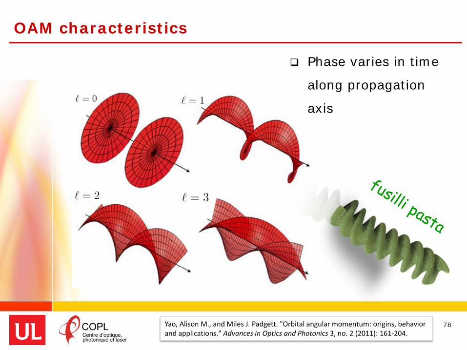
OAM characteristics
Phase varies in time
along propagation
axis
78Yao, Alison M., and Miles J. Padgett. "Orbital angular momentum: origins, behavior and applications." Advances in Optics and Photonics 3, no. 2 (2011): 161-204.

OAM example – 3rd order mode Annular field intensity profile (m=1)
Helical phase front
Circular Polarization (±)
79OAM3,1
( )ie ϕ± l

Why do we call it OAM?
80

Why do we call it OAM?
81
conservation of momentum effect

OAM fibers
Index profile matches OAM mode field intensity profile
(ring shaped)
Vector modes with well separated effective indices
⇒ avoid degeneracy into LP modes
(i.e. at least 10−4)
Effective index separation ⇒ high refractive index contrast
(violates the weakly guiding approximation)
82
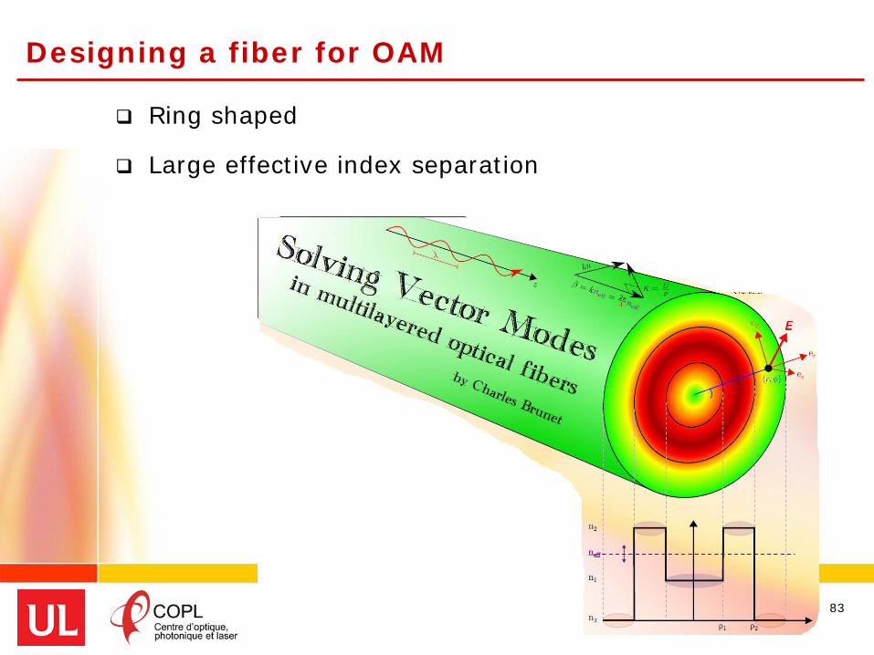
Designing a fiber for OAM
Ring shaped
Large effective index separation
83

OAM fibers
84
"Vortex fiber" (2 OAM states)∆neff ≈ 1.8×10⁻⁴
S. Ramanchandran et al., “Generation and propagation of radially polarized beams in optical fiber,” Optics Letters 34, p.2525 (2009)
N. Bozinovic et al., “Terabit-Scale Orbital Angular Momentum Mode Division multiplexing in Fibers,” Science 340, p. 1545 (2013)
Ring core fibers at UL
Inverse Parabolic Graded Index Fiber (IPGIF)• Smooth gradient profile• Gradient varied to achieve
Hollow core fiber• Hollow core to maximize index contrast• Probe maximum number of modes
Ring core fiber• Analytical tools for designing step index OAM fiber
85
𝛥𝛥𝑛𝑛𝑒𝑒𝑒𝑒𝑒𝑒 > 10−4

waveguide
Ring core fibers at UL
6µm IPGIF
23.2µm
2.4µmHollow core
5.6µm
1.8µmRing core

87
N < 0 : curvature parameter
Inverse Parabolic Graded Index Fiber (IPGIF)
Ung, P. Vaity, L. Wang, Y. Messaddeq, L. A. Rusch and S. LaRochelle, “Few-mode fiber with inverse-parabolic graded-index profile for transmission of OAM-carrying modes,” Optics Express 22, no. 15, pp. 18044-18055 (July 2014).
6µm IPGIF

88
N < 0 : curvature parameter
Inverse Parabolic Graded Index Fiber (IPGIF)
∆nmax=na-n2
N: curvature
a: core radius
a
Ung, P. Vaity, L. Wang, Y. Messaddeq, L. A. Rusch and S. LaRochelle, “Few-mode fiber with inverse-parabolic graded-index profile for transmission of OAM-carrying modes,” Optics Express 22, no. 15, pp. 18044-18055 (July 2014).
6µm IPGIF
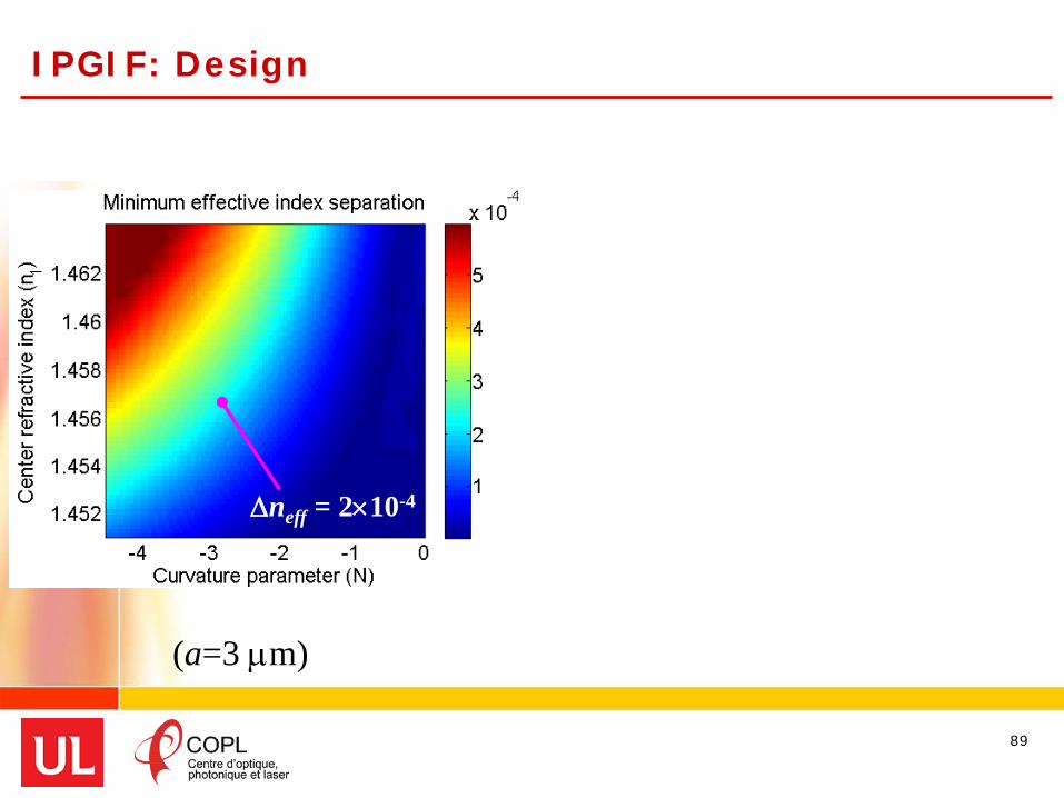
IPGIF: Design
89
∆neff = 2×10⁻⁴
(a=3 µm)

IPGIF: Design
90
(a=3 µm)
∆neff = 2×10⁻⁴
Average loss : 8.6 dB/kmLP01 loss : 6.5 dB/km
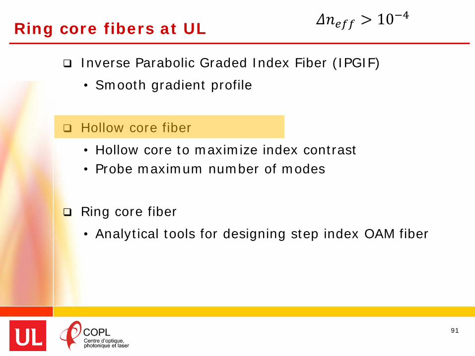
Ring core fibers at UL
Inverse Parabolic Graded Index Fiber (IPGIF)• Smooth gradient profile• Gradient varied to achieve
Hollow core fiber• Hollow core to maximize index contrast• Probe maximum number of modes
Ring core fiber• Analytical tools for designing step index OAM fiber
91
𝛥𝛥𝑛𝑛𝑒𝑒𝑒𝑒𝑒𝑒 > 10−4
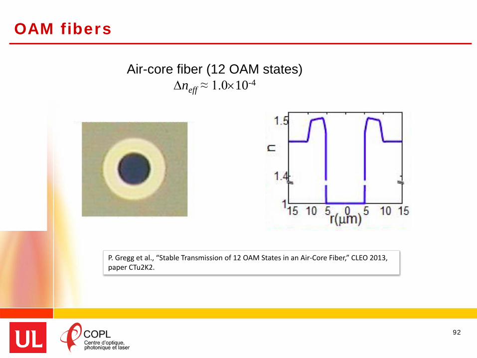
OAM fibers
92
Air-core fiber (12 OAM states)∆neff ≈ 1.0×10⁻⁴
P. Gregg et al., “Stable Transmission of 12 OAM States in an Air-Core Fiber,” CLEO 2013, paper CTu2K2.

Ring-core and trench indices • dictated by material constraints • highest possible index contrast
Optimize• ∆𝑛𝑛eff > 10−4
• Number of supported modes (≥ 16 OAM states)
93
Hollow-Center Ring-Core Fiber: design
C. Brunet, P. Vaity, Y. Messaddeq, S. LaRochelle, and L. A. Rusch, “Design, fabrication and validation of an OAM fiber supporting 36 states,” Optics Express 22, no 21, pp. 26117-26127 (2014).
23.2µm
2.4µm
Hollow core

Hollow-Center Ring-Core Fiber
94

Hollow-Center Ring-Core Fiber
95

Hollow-Center Ring-Core Fiber
96

Hollow-Center Ring-Core Fiber
97
9 OAM orders17 OAM modes36 information channels

Hollow-Center Ring-Core Fiber
98[ ] 4min 1.1 10effn −∆ = ×

99
Right circularpolarization
Left circularpolarization
Hollow-Center Ring-Core Fiber : 1 m transmission
loss few dB/m

Hollow-Center Ring-Core Fiber
100
cut-off

Ring core fibers at UL
Inverse Parabolic Graded Index Fiber (IPGIF)• Smooth gradient profile• Gradient varied to achieve
Hollow core fiber• Hollow core to maximize index contrast• Probe maximum number of modes
Ring core fiber• Analytical tools for designing step index OAM fiber
101
𝛥𝛥𝑛𝑛𝑒𝑒𝑒𝑒𝑒𝑒 > 10−4

Ring Core Fiber – design tools
102
Simple geometry
fiber cross section
refractive index

Ring Core Fiber – design tools
103
Simple geometry
Analytical tools to choose dimensions

Ring Core Fiber – design tools
104
Simple geometry
Analytical tools to choose dimensions• OAM modes supported• Type• Number
410effn −∆ >
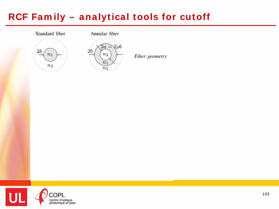
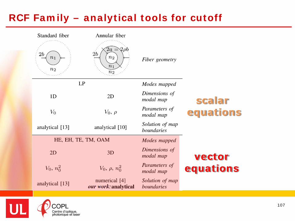
RCF Family – analytical tools for cutoff
105

RCF Family – analytical tools for cutoff
106
scalar equations
RCF Family – analytical tools for cutoff
107
scalar equations
vectorequations

RCF Family – analytical tools for cutoff
108
scalar equations
vectorequations
C. Brunet, B. Ung, P.-A. Bélanger, Y. Messaddeq, S. LaRochelle, and L. A. Rusch, "Vector mode analysis of ring-core fibers: design tools for spatial division multiplexing," Journal of Lightwave Technology 32.23 (2014): 4046-4057.

RCF Family – modal maps
Geometry
Normalized propagation constant
Normalized frequency
109

Modal map
110

Modal map
111
SCF fiber ρ→0

Modal map
112LP mode group
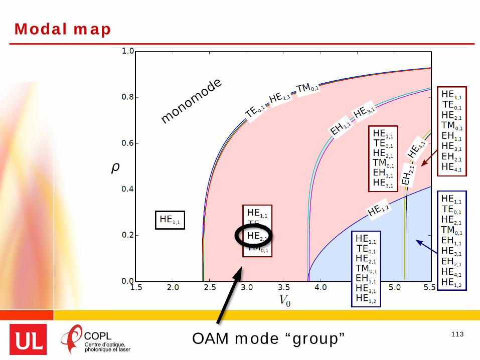
Modal map
113OAM mode “group”

Predicting ∆neff
114C. Brunet, B. Ung, L. Wang, Y. Messaddeq, S. LaRochelle, and L. A. Rusch, "Design of a family of ring-core fibres for OAM transmission studies," Optics Express 23.8 (2015): 10553-10563.

Predicting ∆neff
115
SCF fiber ρ→0
no “fence” ⇒vector modes mix
to form LP

RCF family
116
5.6µm
1.8µm
Ring core
Outline
Motivation – overcoming the Shannon limit
Space Division Multiplexing systems
Fibers for SDM• Background on fibers• Eigenmodes & Few mode fibers
Linearly polarized (LP) modes solution• Multiple input, multiple output (MIMO) processing
Orbital angular momentum modes (OAM) solution• OAM fibers – why we like them & how we design them• OAM at UL• OAM transmission experiments
Conclusion
117

First proof of concept
Optical control of polarization Mode separation facilitated by this control No MIMO processing required
118N. Bozinovic, et al., "Terabit-Scale Orbital Angular Momentum Mode Division Multiplexing in Fibers," Science, vol. 340, pp. 1545-1548, June 28, 2013.
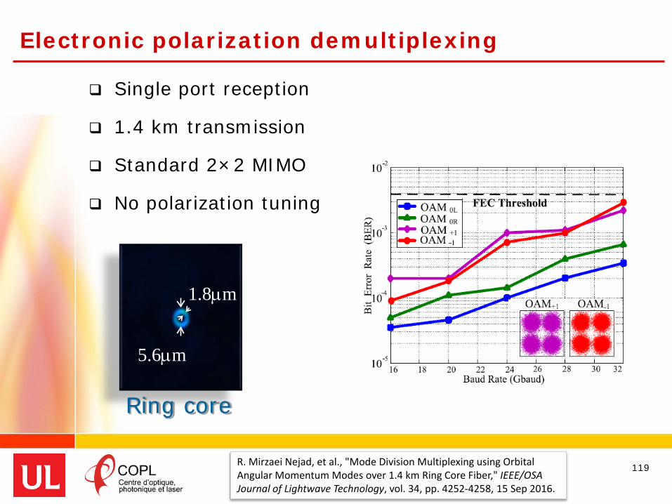
Electronic polarization demultiplexing
Single port reception
1.4 km transmission
Standard 2×2 MIMO
No polarization tuning
119R. Mirzaei Nejad, et al., "Mode Division Multiplexing using Orbital Angular Momentum Modes over 1.4 km Ring Core Fiber," IEEE/OSAJournal of Lightwave Technology, vol. 34, pp. 4252-4258, 15 Sep 2016.
5.6µm
1.8µm
Ring core

Commercial Receivers & OAM Fiber
Heterogeneous transmission (OOK/QPSK)
OAM states separated by commercial 2x2
MIMO
120L. A. Rusch, M. M. Rad, K. Allahverdyan, I. Fazal, and E. Bernier, "Carrying data on the orbital angular momentum of light," IEEE Communications Magazine, vol. 56, pp. 219 - 224, February 2018.
5.6µm
1.8µm
Ring core
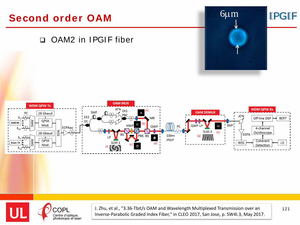
Second order OAM
OAM2 in IPGIF fiber
121J. Zhu, et al., "3.36-Tbit/s OAM and Wavelength Multiplexed Transmission over an Inverse-Parabolic Graded Index Fiber," in CLEO 2017, San Jose, p. SW4I.3, May 2017.
6µm IPGIF

Higher order OAM
122
G. Zhu, et al., "Scalable mode division multiplexed transmission over a 10-km ring-core fiber using high-order orbital angular momentum modes," Optics Express, vol. 26, pp. 594-604, 2018/01/22.
4×4 MIMO over one OAM |order|
8 channelsOAM |4| OAM |5|
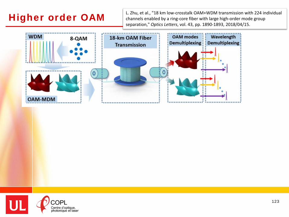
Higher order OAM
123
L. Zhu, et al., "18 km low-crosstalk OAM+WDM transmission with 224 individual channels enabled by a ring-core fiber with large high-order mode group separation," Optics Letters, vol. 43, pp. 1890-1893, 2018/04/15.

Higher order OAM
124
no MIMO; but mode groups, ¼ of channels exploited
L. Zhu, et al., "18 km low-crosstalk OAM+WDM transmission with 224 individual channels enabled by a ring-core fiber with large high-order mode group separation," Optics Letters, vol. 43, pp. 1890-1893, 2018/04/15.

Higher order OAM
125
L. Zhu, et al., "18 km low-crosstalk OAM+WDM transmission with 224 individual channels enabled by a ring-core fiber with large high-order mode group separation," Optics Letters, vol. 43, pp. 1890-1893, 2018/04/15.
K. Ingerslev, et al., "12 Mode, MIMO-Free OAM Transmission," in OFC 2017, Los Angeles, p. M2D.1, 2017/03/19.

Higher order OAM
126
K. Ingerslev, et al., "12 Mode, MIMO-Free OAM Transmission," in OFC 2017, Los Angeles, p. M2D.1, 2017/03/19.
no MIMO; stability once modes adjusted for TX
12 channelsOAM |5| OAM |6|OAM |7|
LP vs. OAM
• Rich set of components• coupling and muxing
• LP modes from eigenmodes that necessarily interact
• high crosstalk• limited channel count
• Requires MIMO processing and multiplexed receivers
• Early stages of research• coupling issues still open
• OAM modes from eigenmodes that can be designed to avoid interaction
• low crosstalk• better channel count
• DSP & RX simpler• No MIMO processing needed• Standard 2×2
127

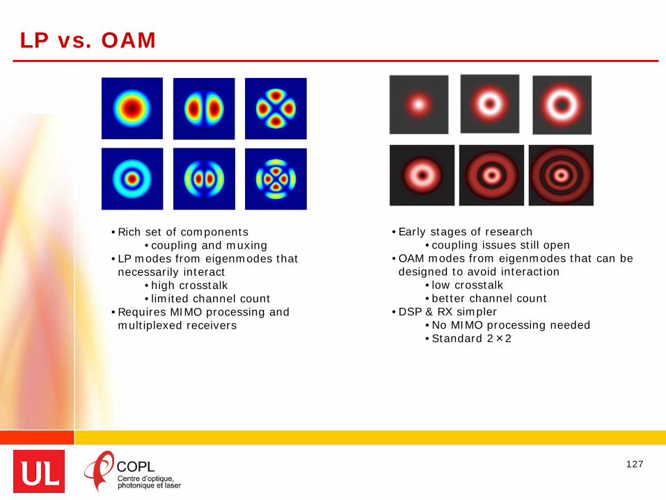
LP vs. OAM
• Rich set of components• coupling and muxing
• LP modes from eigenmodes that necessarily interact
• high crosstalk• limited channel count
• Requires MIMO processing and multiplexed receivers
• Early stages of research• coupling issues still open
• OAM modes from eigenmodes that can be designed to avoid interaction
• low crosstalk• better channel count
• DSP & RX simpler• No MIMO processing needed• Standard 2×2
128
target very low fiber interactions, but what about splices, etc.?; avoid MIMO
Different Strategiesembrace strong fiber interactions
to simplify components; exploit MIMO

Some other promising directions
a single core, a single mode
a single core, multiple modes
ring core fiber
129

Some other promising directions
a single core, a single mode
a single core, multiple modes
elliptical core fibers
linearly polarized VECTOR modes hold promise
ring core fiber
130

Conclusion
131
• Transmission of OAM modes still very new
• Design and fabrication of optical fibers is challenging
• Need to better understand mode-coupling and cross-talk mechanisms
- optimize designs
- target most appropriate OAM modes
• Integrated components are needed as well as fibers

Acknowledgments
Alessandro CorsiDr. Charles BrunetDr. Reza NejadDr. Karen AllahverdyanDr. Pravin VaityDr. Lixian WangProf. Sophie LaRochelleProf. Younès Messaddeq
Canada Research Chairs
Prof. Bora UngIrfan FazalMohammad RadEric Bernier
132