transporters • electrical system vito/viano (model 639
TRANSCRIPT
Transporters • Electrical System VITO/VIANO (Model 639)
Wiring Diagrams Technical training for Customers
r As at 06/05
amb
Wiring Diagram Manuals Part Number: Z6517 2111 02
This document is intended solely for use in training and is not subject to regular updating. Part numbers and documentation included in this document may change and the latest information should always be used.
Printed in England
2005 Copyright DaimlerChrysler UK LTD
Publisher: Mercedes-Benz CV Electrics & Telematics Team
This document with all its sections is protected under the laws of copyright. Its use for any purpose whatsoever requires the prior written consent of DaimlerChrysler UK LTD. This applies in particular to its reproduction, distribution, modification, translation, recording on microfilm or storage and/or processing in electronic systems, including databases and on-line services.
Note: The term »employees« does not imply any preference of gender and incorporated male and refers to male and female employees alike.
06/05 Transporters • Electrics <>Van - Electrical Systems Wiring Diagrams VITO (Model 639)
Contents
Chapter Title
1 Use of wiring diagrams
2 Abbreviations for wiring diagrams
3 Location and assignment of ground points
4 Location and assignment of plug connectors
5 Battery starting charging circuit
6 Voltage supply fuses
7 Fuse and relay board (SRB)
8 Signal Acquisition and actuation module (SAM)
9 Exterior lights
10 Central locking
11 CAN bus
12 Instrument cluster (IC)
13 Electronic ignition switch (EIS)
14 Electronic stability control (ESP)
15 Common rail diesel injection (CDI)
16 Standard heater
06/05 Transporters • Electrics <>Van - Electrical Systems Wiring Diagrams VITO (Model 639)
Use of Wiring Diagrams Chapter 1
OV00.01-S-1901-03VA Use of wiring diagrams
The wiring diagrams are prepared as function diagrams or controlaWiring diagramsunit diagrams and are built up as follows:The wiring diagrams are assigned to the familiar function groupsa-Function diagrams00-91. The systems are listed alphabetically with an indication of The control units and electrical components belonging to the the function group/ function subgroup in the "Search aid for all function are shown as symbols. The functional connections are wiring diagram groups" realized by direct lines or by the data bus.OV00.01-S-1901VA or A3 (paper version).-Control unit diagramsThe wiring diagrams are filed in the respective function groupaControl units are represented complete with all connected arranged according to the PE number,components. The feed of the control units appears first.e.g.: PE07.16-S-2000VAThe wiring diagrams also contain linkages of possible versions and PE07.16-S-2000IVBfunctions.
To check the completeness of the volume the sequence of the Linkages, recognizable as versions, are framed and provided with wiring diagrams filed can be seen from the lists of contents of the an abbreviated designation/ abbreviation.respective function group. For supplements the wiring diagrams The versions are designated with 1should be filed as per the supplement sheet.and 2e.g.: PE00.19-P-1100VA Overview of wiring diagrams....------------------------------------------------------------------------------------------------------------------------------------------------------------------------
Notes on the accompanying documents for connectors/ terminalablocks (B1)
Special equipment (SA) is specifically highlighted in the notes column. For connectors, which are installed in special equipment, the special equipment is specified in the notes column in the row in front of the connector designation. For connectors, which are installed as standard, special equipment specification is noted directly at the respective jack and/or connector.The feed of the terminal blocks is shown by means of an arrow pointing to the left, the outputs by means of arrows pointing to the right. The grouping of the individual variants/special equipment (SA) is highlighted by means of broken lines. All outputs to components, which are installed as standard, are listed up to the first broken line.
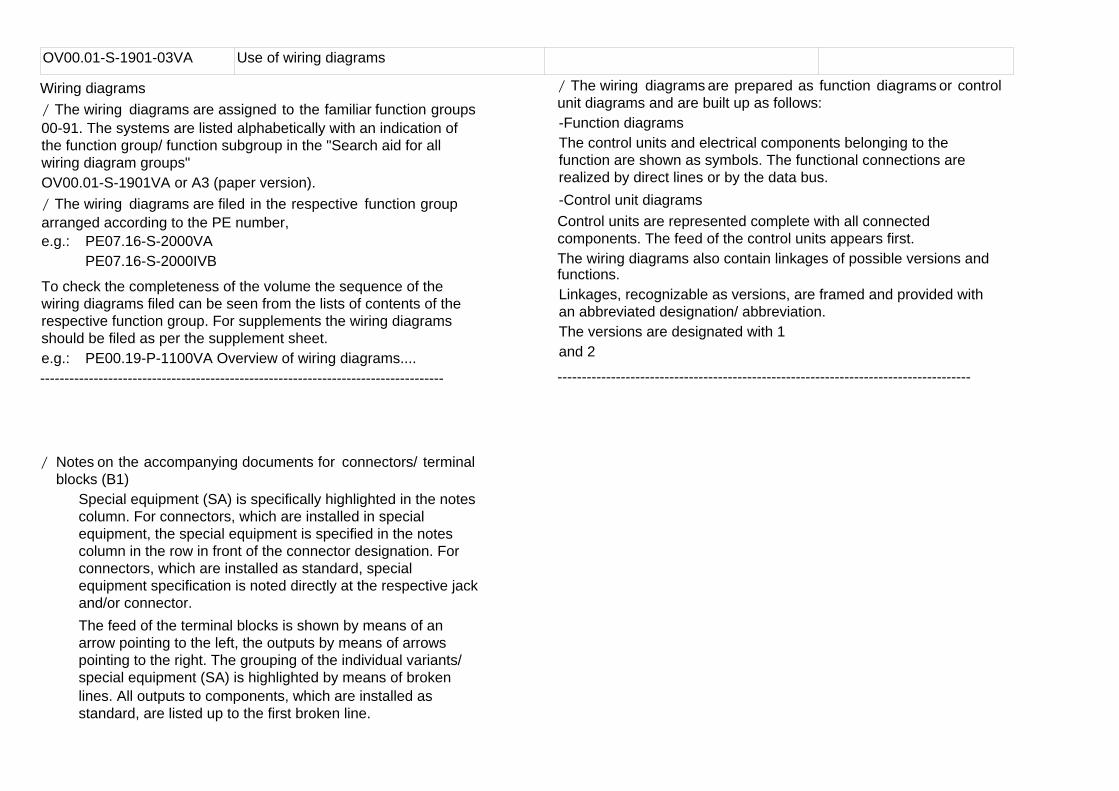
Connection designationa Componentb Clutchc Socket
P00.19-0402-01
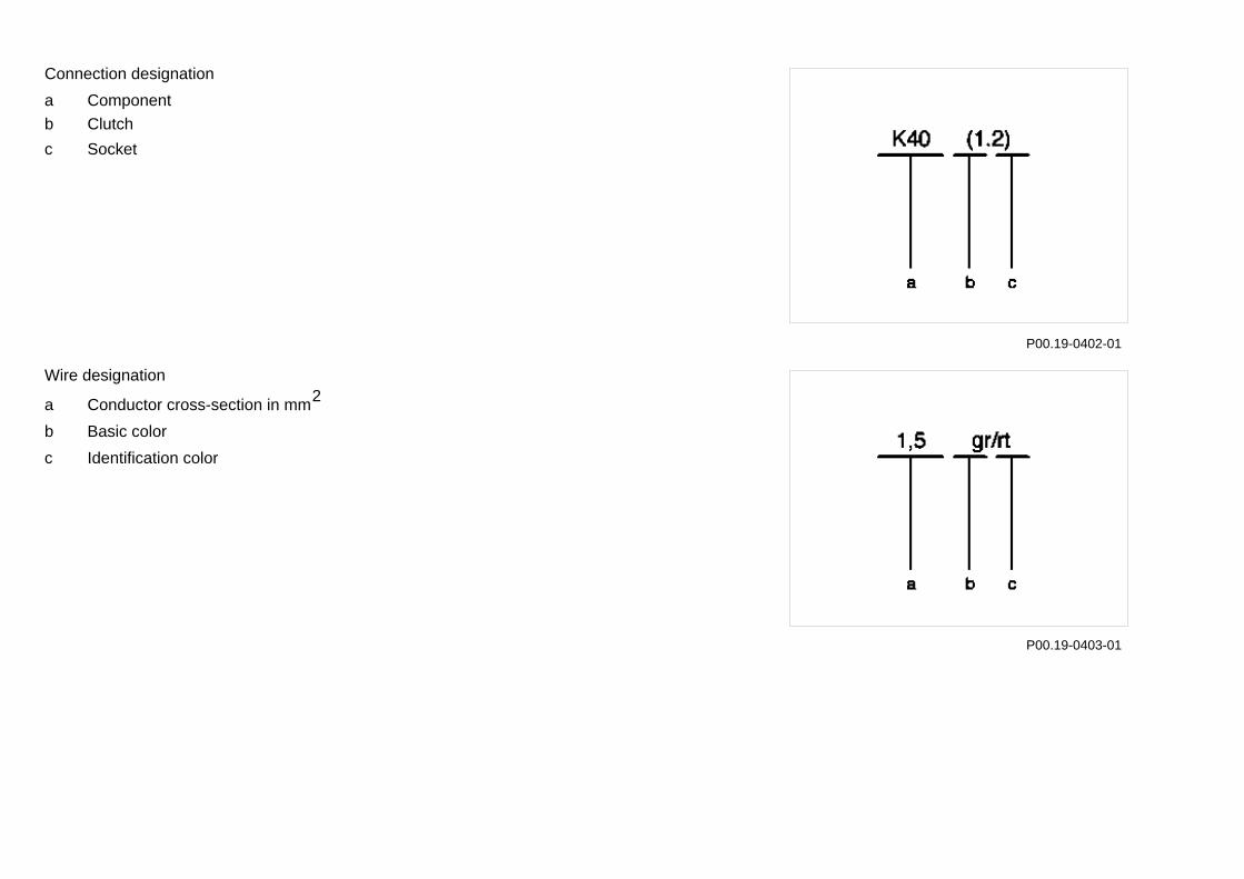
Wire designation2a Conductor cross-section in mm
b Basic colorc Identification color
P00.19-0403-01
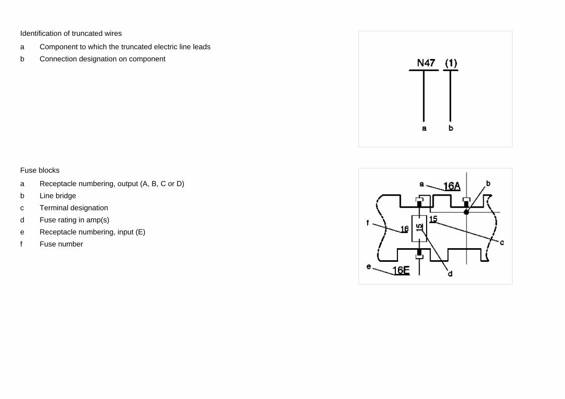
Identification of truncated wires
a Component to which the truncated electric line leadsb Connection designation on component
Fuse blocks
a Receptacle numbering, output (A, B, C or D)b Line bridgec Terminal designationd Fuse rating in amp(s)e Receptacle numbering, input (E)f Fuse number
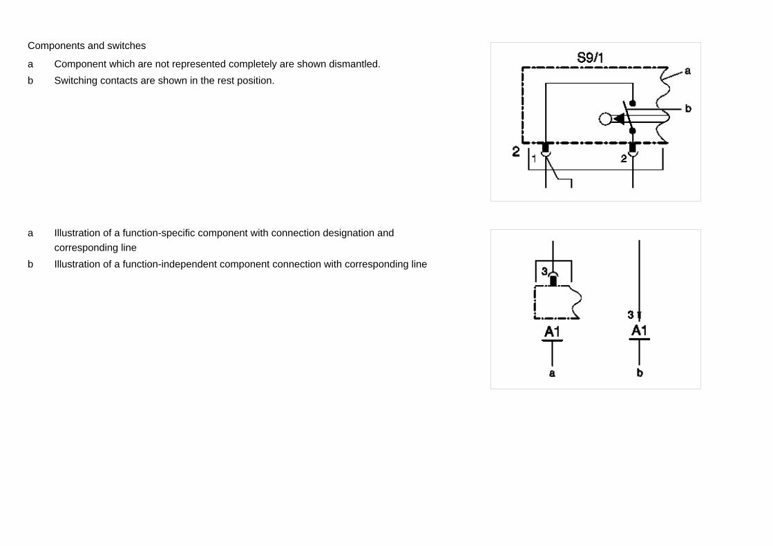
Components and switches
a Component which are not represented completely are shown dismantled.b Switching contacts are shown in the rest position.
a Illustration of a function-specific component with connection designation and corresponding line
b Illustration of a function-independent component connection with corresponding line
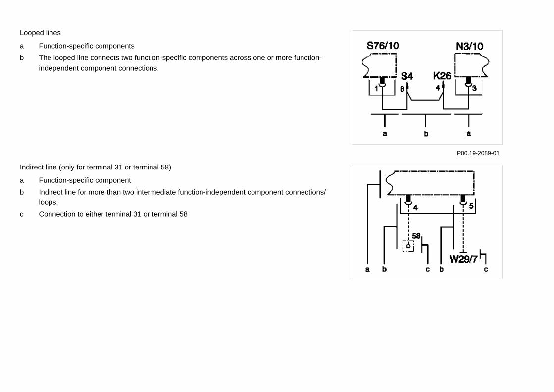
Looped lines
a Function-specific componentsb The looped line connects two function-specific components across one or more function-
independent component connections.
P00.19-2089-01
Indirect line (only for terminal 31 or terminal 58)
a Function-specific componentb Indirect line for more than two intermediate function-independent component connections/
loops.c Connection to either terminal 31 or terminal 58
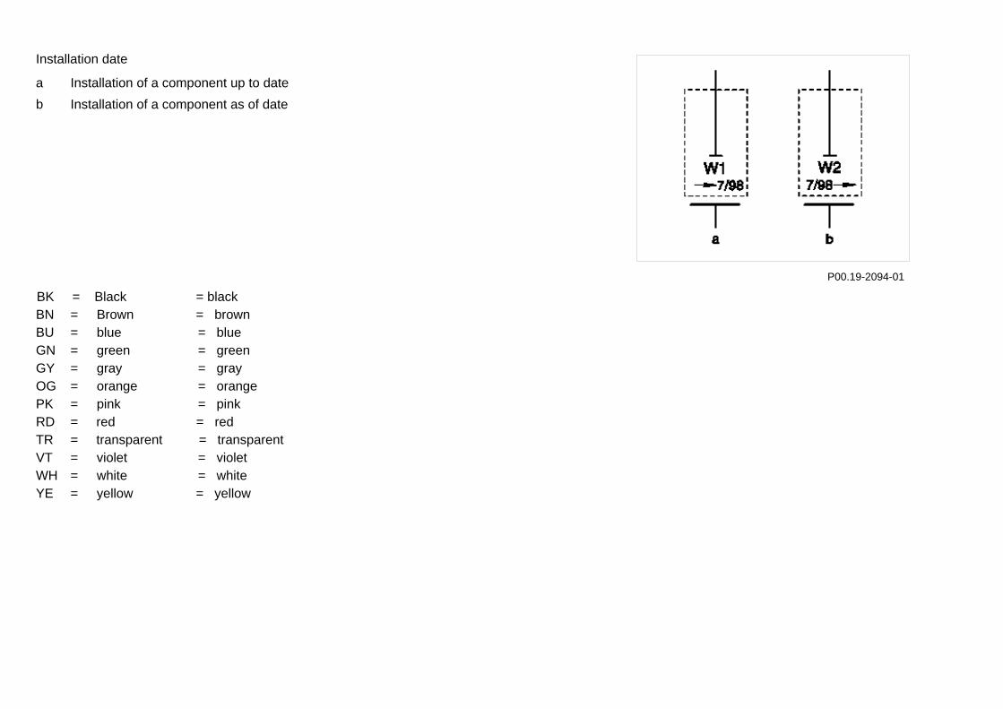
Installation date
a Installation of a component up to dateb Installation of a component as of date
P00.19-2094-01 BK = Black = black
BN = Brown = brownBU = blue = blueGN = green = greenGY = gray = grayOG = orange = orangePK = pink = pinkRD = red = redTR = transparent = transparentVT = violet = violetWH = white = whiteYE = yellow = yellow Page 7
06/05 Transporters • Electrics <>Van - Electrical Systems Wiring Diagrams VITO (Model 639)
Abbreviations for Wiring Diagrams Chapter 2
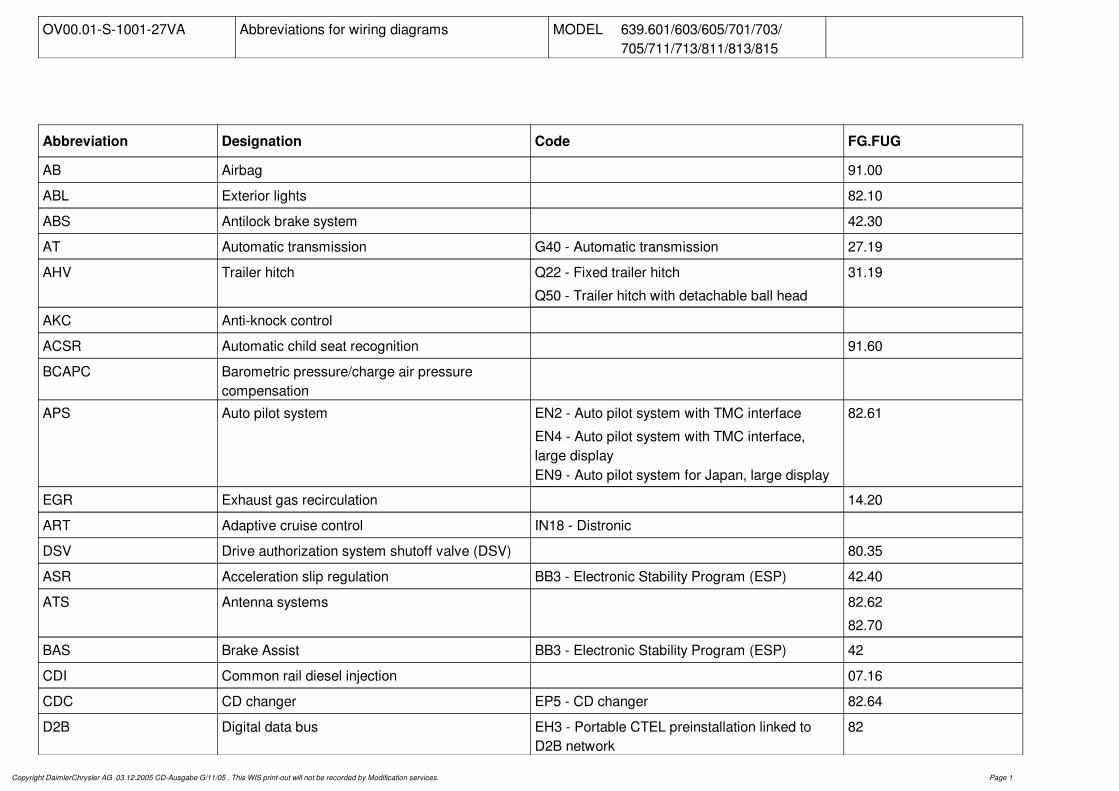
OV00.01-S-1001-27VA Abbreviations for wiring diagrams MODEL 639.601/603/605/701/703/ 705/711/713/811/813/815
Abbreviation Designation Code FG.FUG
AB Airbag 91.00
ABL Exterior lights 82.10
ABS Antilock brake system 42.30
AT Automatic transmission G40 - Automatic transmission 27.19
AHV Trailer hitch Q22 - Fixed trailer hitch
Q50 - Trailer hitch with detachable ball head
31.19
AKC Anti-knock control
ACSR Automatic child seat recognition 91.60
BCAPC Barometric pressure/charge air pressure compensation
APS Auto pilot system EN2 - Auto pilot system with TMC interface
EN4 - Auto pilot system with TMC interface, large displayEN9 - Auto pilot system for Japan, large display
82.61
EGR Exhaust gas recirculation 14.20
ART Adaptive cruise control IN18 - Distronic
DSV Drive authorization system shutoff valve (DSV) 80.35
ASR Acceleration slip regulation BB3 - Electronic Stability Program (ESP) 42.40
ATS Antenna systems 82.62
82.70
BAS Brake Assist BB3 - Electronic Stability Program (ESP) 42
CDI Common rail diesel injection 07.16
CDC CD changer EP5 - CD changer 82.64
D2B Digital data bus EH3 - Portable CTEL preinstallation linked to D2B network
82
Copyright DaimlerChrysler AG 03.12.2005 CD-Ausgabe G/11/05 . This WIS print-out will not be recorded by Modification services. Page 1
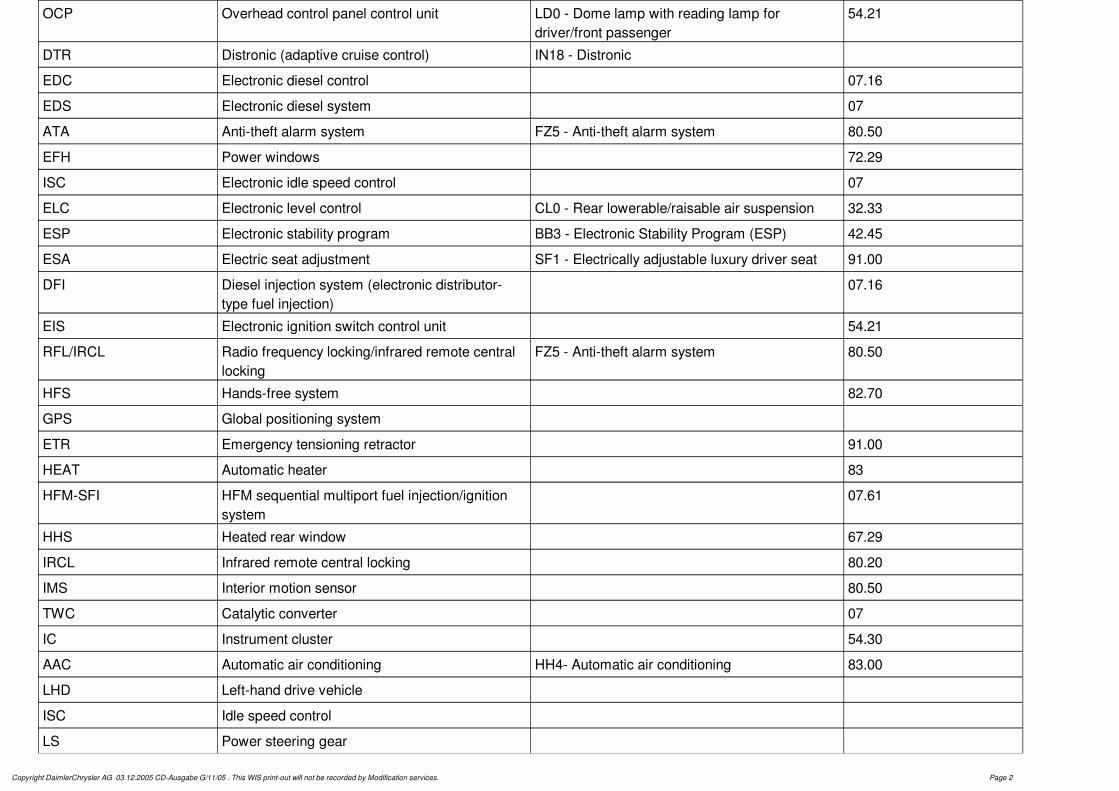
OCP Overhead control panel control unit LD0 - Dome lamp with reading lamp for driver/front passenger
54.21
DTR Distronic (adaptive cruise control) IN18 - Distronic
EDC Electronic diesel control 07.16
EDS Electronic diesel system 07
ATA Anti-theft alarm system FZ5 - Anti-theft alarm system 80.50
EFH Power windows 72.29
ISC Electronic idle speed control 07
ELC Electronic level control CL0 - Rear lowerable/raisable air suspension 32.33
ESP Electronic stability program BB3 - Electronic Stability Program (ESP) 42.45
ESA Electric seat adjustment SF1 - Electrically adjustable luxury driver seat 91.00
DFI Diesel injection system (electronic distributor-type fuel injection)
07.16
EIS Electronic ignition switch control unit 54.21
RFL/IRCL Radio frequency locking/infrared remote central locking
FZ5 - Anti-theft alarm system 80.50
HFS Hands-free system 82.70
GPS Global positioning system
ETR Emergency tensioning retractor 91.00
HEAT Automatic heater 83
HFM-SFI HFM sequential multiport fuel injection/ignition system
07.61
HHS Heated rear window 67.29
IRCL Infrared remote central locking 80.20
IMS Interior motion sensor 80.50
TWC Catalytic converter 07
IC Instrument cluster 54.30
AAC Automatic air conditioning HH4- Automatic air conditioning 83.00
LHD Left-hand drive vehicle
ISC Idle speed control
LS Power steering gear
Copyright DaimlerChrysler AG 03.12.2005 CD-Ausgabe G/11/05 . This WIS print-out will not be recorded by Modification services. Page 2
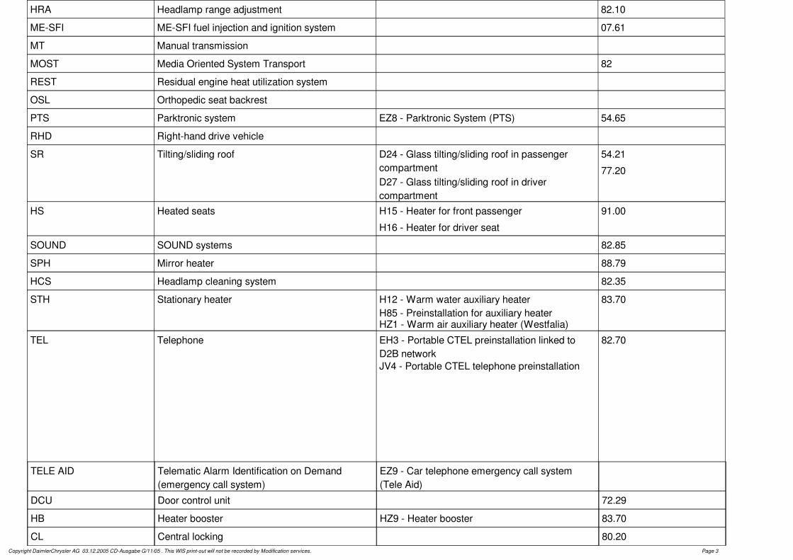
HRA Headlamp range adjustment 82.10
ME-SFI ME-SFI fuel injection and ignition system 07.61
MT Manual transmission
MOST Media Oriented System Transport 82
REST Residual engine heat utilization system
OSL Orthopedic seat backrest
PTS Parktronic system EZ8 - Parktronic System (PTS) 54.65
RHD Right-hand drive vehicle
SR Tilting/sliding roof D24 - Glass tilting/sliding roof in passenger compartmentD27 - Glass tilting/sliding roof in driver compartment
54.21
77.20
HS Heated seats H15 - Heater for front passenger
H16 - Heater for driver seat
91.00
SOUND SOUND systems 82.85
SPH Mirror heater 88.79
HCS Headlamp cleaning system 82.35
STH Stationary heater H12 - Warm water auxiliary heaterH85 - Preinstallation for auxiliary heaterHZ1 - Warm air auxiliary heater (Westfalia)
83.70
TEL Telephone EH3 - Portable CTEL preinstallation linked to D2B networkJV4 - Portable CTEL telephone preinstallation
82.70
Copyright DaimlerChrysler AG 03.12.2005 CD-Ausgabe G/11/05 . This WIS print-out will not be recorded by Modification services. Page 3
TELE AID Telematic Alarm Identification on Demand (emergency call system)
EZ9 - Car telephone emergency call system (Tele Aid)
DCU Door control unit 72.29
HB Heater booster HZ9 - Heater booster 83.70
CL Central locking 80.20
Copyright DaimlerChrysler AG 03.12.2005 CD-Ausgabe G/11/05 . This WIS print-out will not be recorded by Modification services. Page 4
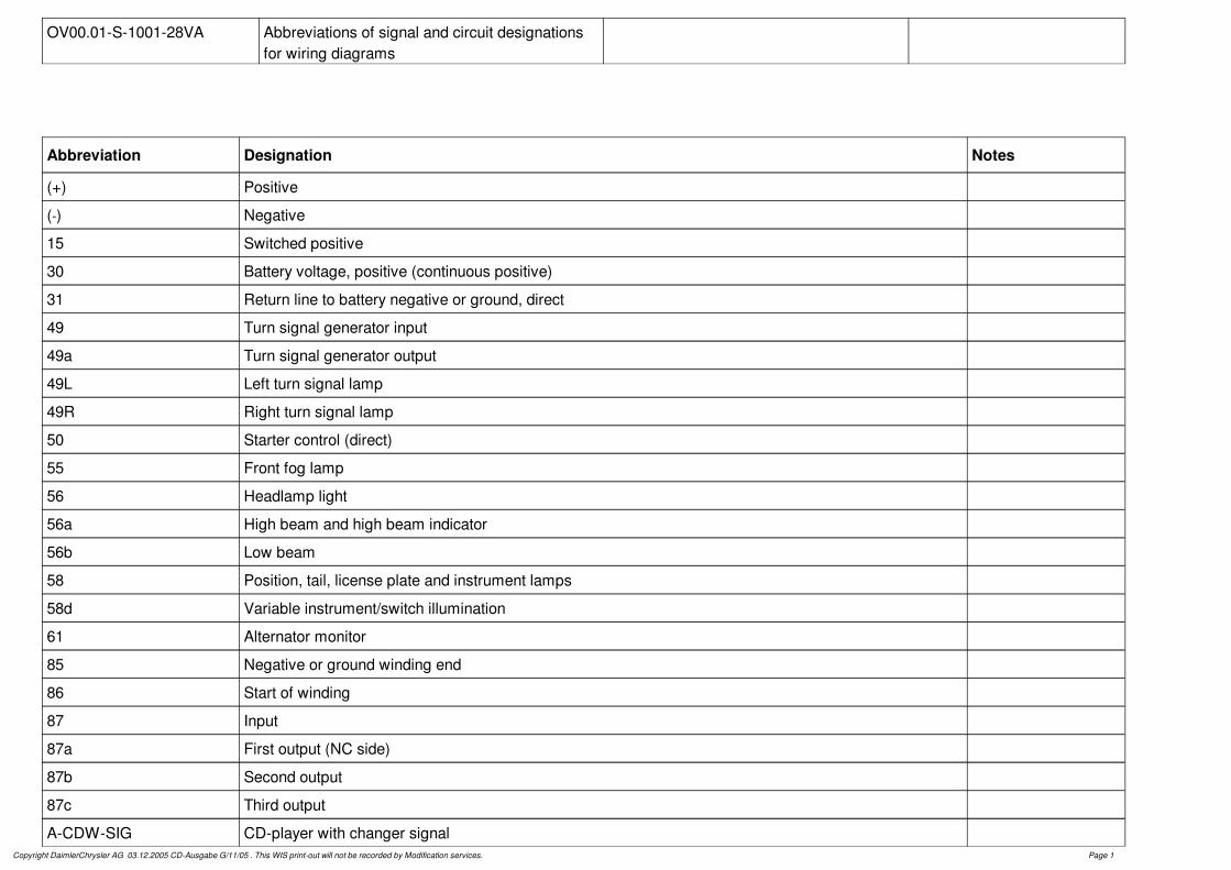
OV00.01-S-1001-28VA Abbreviations of signal and circuit designations for wiring diagrams
Abbreviation Designation Notes
(+) Positive
(-) Negative
15 Switched positive
30 Battery voltage, positive (continuous positive)
31 Return line to battery negative or ground, direct
49 Turn signal generator input
49a Turn signal generator output
49L Left turn signal lamp
49R Right turn signal lamp
50 Starter control (direct)
55 Front fog lamp
56 Headlamp light
56a High beam and high beam indicator
56b Low beam
58 Position, tail, license plate and instrument lamps
58d Variable instrument/switch illumination
61 Alternator monitor
85 Negative or ground winding end
86 Start of winding
87 Input
87a First output (NC side)
87b Second output
87c Third output
A-CDW-SIG CD-player with changer signalCopyright DaimlerChrysler AG 03.12.2005 CD-Ausgabe G/11/05 . This WIS print-out will not be recorded by Modification services. Page 1
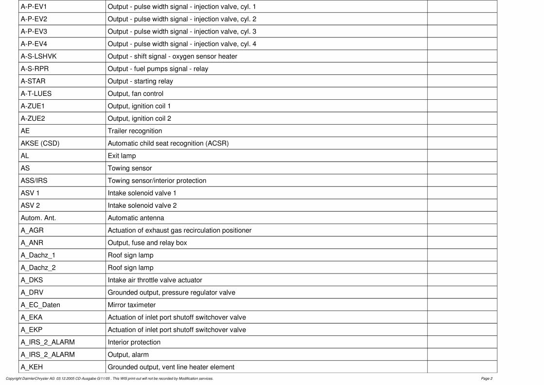
A-P-EV1 Output - pulse width signal - injection valve, cyl. 1
A-P-EV2 Output - pulse width signal - injection valve, cyl. 2
A-P-EV3 Output - pulse width signal - injection valve, cyl. 3
A-P-EV4 Output - pulse width signal - injection valve, cyl. 4
A-S-LSHVK Output - shift signal - oxygen sensor heater
A-S-RPR Output - fuel pumps signal - relay
A-STAR Output - starting relay
A-T-LUES Output, fan control
A-ZUE1 Output, ignition coil 1
A-ZUE2 Output, ignition coil 2
AE Trailer recognition
AKSE (CSD) Automatic child seat recognition (ACSR)
AL Exit lamp
AS Towing sensor
ASS/IRS Towing sensor/interior protection
ASV 1 Intake solenoid valve 1
ASV 2 Intake solenoid valve 2
Autom. Ant. Automatic antenna
A_AGR Actuation of exhaust gas recirculation positioner
A_ANR Output, fuse and relay box
A_Dachz_1 Roof sign lamp
A_Dachz_2 Roof sign lamp
A_DKS Intake air throttle valve actuator
A_DRV Grounded output, pressure regulator valve
A_EC_Daten Mirror taximeter
A_EKA Actuation of inlet port shutoff switchover valve
A_EKP Actuation of inlet port shutoff switchover valve
A_IRS_2_ALARM Interior protection
A_IRS_2_ALARM Output, alarm
A_KEH Grounded output, vent line heater elementCopyright DaimlerChrysler AG 03.12.2005 CD-Ausgabe G/11/05 . This WIS print-out will not be recorded by Modification services. Page 2
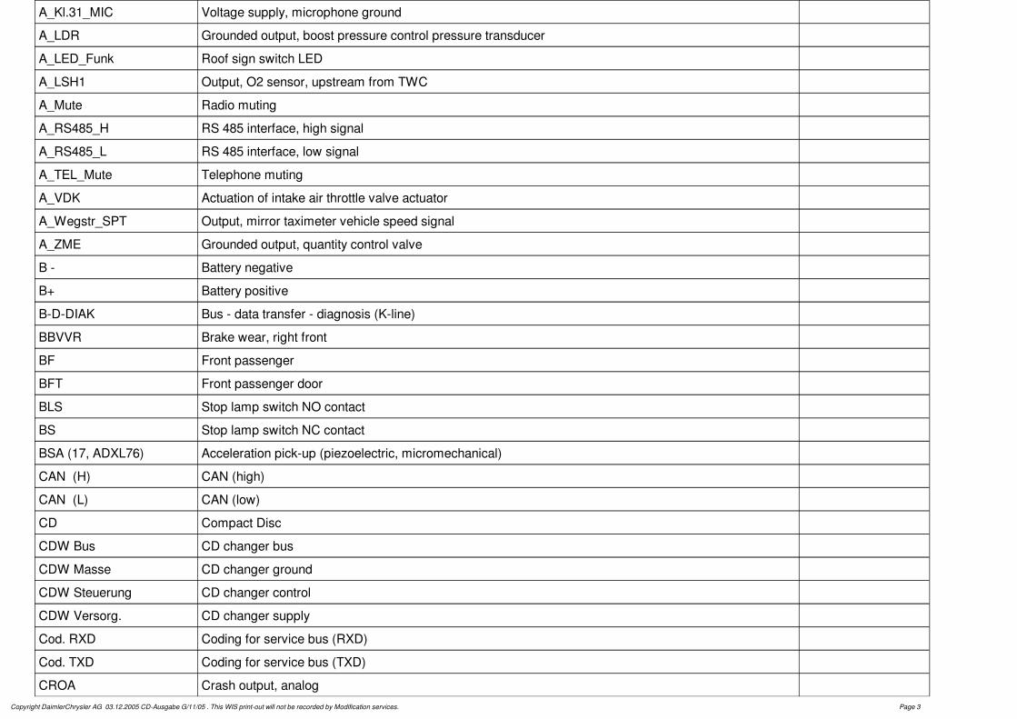
A_Kl.31_MIC Voltage supply, microphone ground
A_LDR Grounded output, boost pressure control pressure transducer
A_LED_Funk Roof sign switch LED
A_LSH1 Output, O2 sensor, upstream from TWC
A_Mute Radio muting
A_RS485_H RS 485 interface, high signal
A_RS485_L RS 485 interface, low signal
A_TEL_Mute Telephone muting
A_VDK Actuation of intake air throttle valve actuator
A_Wegstr_SPT Output, mirror taximeter vehicle speed signal
A_ZME Grounded output, quantity control valve
B - Battery negative
B+ Battery positive
B-D-DIAK Bus - data transfer - diagnosis (K-line)
BBVVR Brake wear, right front
BF Front passenger
BFT Front passenger door
BLS Stop lamp switch NO contact
BS Stop lamp switch NC contact
BSA (17, ADXL76) Acceleration pick-up (piezoelectric, micromechanical)
CAN (H) CAN (high)
CAN (L) CAN (low)
CD Compact Disc
CDW Bus CD changer bus
CDW Masse CD changer ground
CDW Steuerung CD changer control
CDW Versorg. CD changer supply
Cod. RXD Coding for service bus (RXD)
Cod. TXD Coding for service bus (TXD)
CROA Crash output, analogCopyright DaimlerChrysler AG 03.12.2005 CD-Ausgabe G/11/05 . This WIS print-out will not be recorded by Modification services. Page 3
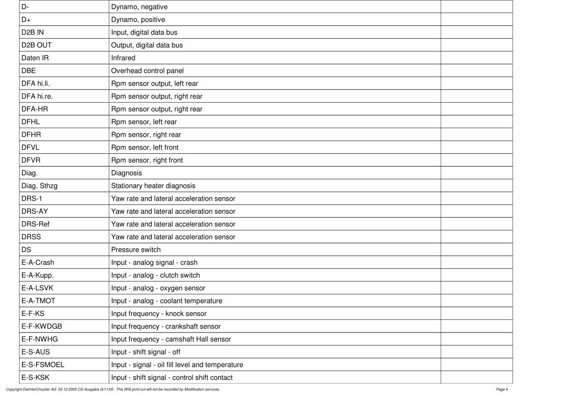
D- Dynamo, negative
D+ Dynamo, positive
D2B IN Input, digital data bus
D2B OUT Output, digital data bus
Daten IR Infrared
DBE Overhead control panel
DFA hi.li. Rpm sensor output, left rear
DFA hi.re. Rpm sensor output, right rear
DFA-HR Rpm sensor output, right rear
DFHL Rpm sensor, left rear
DFHR Rpm sensor, right rear
DFVL Rpm sensor, left front
DFVR Rpm sensor, right front
Diag. Diagnosis
Diag. Sthzg Stationary heater diagnosis
DRS-1 Yaw rate and lateral acceleration sensor
DRS-AY Yaw rate and lateral acceleration sensor
DRS-Ref Yaw rate and lateral acceleration sensor
DRSS Yaw rate and lateral acceleration sensor
DS Pressure switch
E-A-Crash Input - analog signal - crash
E-A-Kupp. Input - analog - clutch switch
E-A-LSVK Input - analog - oxygen sensor
E-A-TMOT Input - analog - coolant temperature
E-F-KS Input frequency - knock sensor
E-F-KWDGB Input frequency - crankshaft sensor
E-F-NWHG Input frequency - camshaft Hall sensor
E-S-AUS Input - shift signal - off
E-S-FSMOEL Input - signal - oil fill level and temperature
E-S-KSK Input - shift signal - control shift contactCopyright DaimlerChrysler AG 03.12.2005 CD-Ausgabe G/11/05 . This WIS print-out will not be recorded by Modification services. Page 4