transportation research circular - asphalt circular on... · 6 transportation research circular...
TRANSCRIPT

TRANSPORTATION RESEARCH
CIRCULARNumber 503 December 2001
Perpetual Bituminous Pavements

TRANSPORTATION Number 503, December 2001RESEARCH ISSN 0097-8515CIRCULAR
Perpetual Bituminous Pavements
TRB Committee on General Issues in Asphalt Technology (A2D05)
Joe W. Button, Chair
J. Don BrockRonald CollinsEileen ConnollyDale S. Decker
Denis E. DonnellyFrank Fee
Thomas P. HarmanRobert D. HoranGerald A. Huber
Prithvi S. KandhalGayle N. King
David E. NewcombHarold R. Paul
James A. ScherocmanScott Shuler
H. Barry TakallouDonald E. WatsonJohn J. Weigel, Jr.
Randy C. West
Frederick D. Hejl, TRB Staff Representative
Subscriber category Transportation Research BoardIIIB materials and construction National Research Center
2101 Constitution Avenue, NWWebsite: TRB.org Washington, DC 20418
The Transportation Research Board is a unit of the National Research Council, which serves as an independent adviser to thefederal government on scientific and technical questions of national importance. The National Research Council, jointlyadministered by the National Academy of Sciences, National Academy of Engineering, and the Institute of Medicine, brings theresources of the entire scientific and technical community to bear on national problems through its volunteer advisorycommittees.
The Transportation Research Board is distributing this Circular to make the information contained herein available for use byindividual practitioners in state and local transportation agencies, researchers in academic institutions, and other members of thetransportation research community. The information in this Circular was taken directly from the submissions of the authors. Thisdocument is not a report of the National Research Council or the National Academy of Sciences.

Foreword
he concept of perpetual asphalt pavements is rapidly gaining acceptance in theUnited States. The idea is to extend the 20-year life expectancies of hot-mix asphalt
pavement to greater than 50 years. To do so requires combining a rut-resistant,impermeable, and wear-resistant top structural layer with a rut-resistant and durableintermediate layer and a fatigue-resistant and durable base layer. With these pavements,only periodic surface restoration is necessary, offering advantages in speed ofconstruction (user delay costs) and construction costs.
This concept was explored and discussed at a two-part session on perpetualbituminous pavements at the 2001 Transportation Research Board Annual Meeting. Thepapers in this document were written following the session and are based on thepresentations; the papers in this Circular have not undergone peer review.
Appreciation is expressed to Frank Fee, Citgo Asphalt Refining Company, for hisefforts in developing this Circular.
T

Contents
Concepts of Perpetual Pavements................................................................................................ 4David E. Newcomb, National Asphalt Pavement AssociationMark Buncher, Asphalt InstituteIra J. Huddleston, Asphalt Pavement Association of Oregon
Development and Uses of Hard-Grade Asphalt and ofHigh-Modulus Asphalt Mixes in France ................................................................................... 12Jean-François Corté, Laboratoire Central des Ponts et Chaussées (France)
Design and Assessment of Long-Life Flexible Pavements ....................................................... 32Michael Nunn and Brian W. Ferne, Transport Research Laboratory (United Kingdom)
Long-Life Rehabilitation Design and Construction:I-710 Freeway, Long Beach, California .................................................................................... 50Jim St. Martin, Asphalt Pavement Association, CaliforniaJohn T. Harvey, Fenella Long, Eul-Bum Lee, and Carl L. Monismith,
University of California–BerkeleyKevin Herritt, California Department of Transportation
Hot-Mix Asphalt Layer Thickness Design for Longer-Life Bituminous Pavements ............ 66Harold L. Von Quintus, Fugro-Brent Rauhut Engineering, Inc.
Evaluation of Top-Down Cracking in Thick Asphalt Pavements and theImplications for Pavement Design ............................................................................................. 79Leslie Ann Myers, ERES ConsultantsReynaldo Roque, University of Florida
Study of Long-Lasting Pavements in Washington State ......................................................... 88Joe P. Mahoney, University of Washington
Development of Long-Life Overlays for Existing Pavement InfrastructureProjects with Surface Cracking in New Jersey ........................................................................ 96Geoffrey Rowe, Abatech, Inc.Robert Sauber, New Jersey Department of TransportationFrank Fee, Citgo, Inc.Nassef Soliman, Parsons-Brinckerhoff–FG, Inc.
Illinois Extended-Life Hot-Mix Asphalt Pavements .............................................................. 108Eric Harm, Illinois Department of Transportation
AppendixPerpetual Bituminous Pavements Authors.................................................................................. 114
4
Concepts of Perpetual PavementsDAVID E. NEWCOMB
National Asphalt Pavement Association
MARK BUNCHERAsphalt Institute
IRA J. HUDDLESTONAsphalt Pavement Association of Oregon
The construction of long-lasting hot mix asphalt pavements has been practiced for a number ofdecades in the United States. Full-depth (asphalt courses used for all layers above subgrade) anddeep-strength (asphalt surface and asphalt base over a minimal aggregate base above subgrade)pavements were originally designed for 20-year life expectancies. One of the primary advantages tothese designs was that the total pavement sections were thinner when compared to conventionaldesigns of asphalt over thick aggregate bases. As these full-depth and deep-strength pavementsperformed beyond their design lives, the vast majority only required surface restoration such as athin overlays or mill and overlay. This practice of replacing only the surface offers a number ofrehabilitation advantages in terms of speed of construction (user delay costs) and constructioncosts. The challenge for today is to obtain a longer surface life on a long-lasting asphalt supportstructure. Recent efforts in materials selection, mixture design, performance testing, and pavementdesign offer a methodology which may be employed to obtain very long-term performance fromasphalt pavement structures (greater than 50 years) while periodically (approximately every 20years) replacing the surface (top 25 to 100 mm) of the pavement. This concept has been proposedfor use in Europe and it is rapidly gaining acceptance in the United States. The common theme inthese approaches is to combine a rut resistant, impermeable, and wear resistant top structurallayer with a rut resistant and durable intermediate layer and a fatigue resistant and durable baselayer.
he concept of long-lasting asphalt pavements is not new. Full-depth and deep-strength asphaltpavement structures have been constructed since the 1960s. Full-depth pavements are
constructed directly on subgrade soils and deep-strength sections are placed on relatively thin (4 to 6in.) granular base courses. One of the chief advantages of these pavements is that the overall sectionof the pavement is thinner than those employing thick granular base courses. Such pavements havethe added advantage of significantly reducing the potential for fatigue cracking by minimizing thetensile strains at the bottom of the asphalt layer. Furthermore, a study by the National Center forAsphalt Technology suggests that when rutting occurs in thick pavements, it is likely to be confinedto the top 2 in. of the structure (1). When this occurs, an economical solution is to remove the toplayer of material and replace it to the same level (mill and fill).
Thick asphalt pavements must be designed and constructed to ensure performance for thetraffic, climate, and soils in given areas. For example, unless proper attention is given to frostprotection, ride quality may degenerate from good to poor in a matter of months because ofdifferential frost heave in the subgrade. Other performance problems in thick asphalt pavementscould include a lack of durability (stripping) in intermediate layers and thermal cracking allowed
T

Newcomb et al. 5
to progress to very severe levels causing a loss of ride quality and secondary fatigue cracking.While these distresses are not unique to thick asphalt pavements, their effects become magnifiedby the amount of material that must be dealt with when correcting them.
In a case study representative of good performing pavements, a recent review of thick (200mm or greater) asphalt pavements on Interstate 90 through the state of Washington revealed thatnone of these sections had ever been rebuilt for structural reasons (2). The pavement ages rangedfrom 23 to 35 years, and thick asphalt concrete (AC) pavements on this route comprise 40percent of the length (about 225 out of 580 km). West of the Cascade Mountains, near Seattle,the average age at resurfacing was 18.5 years. On the eastern side of the state, the average timeuntil first resurfacing was 12.4 years and the time until second resurfacing was 12.2 years. Thistype of performance, while good, can be significantly improved with new technology.
Recent efforts in materials selection, mixture design, performance testing, and pavementdesign offer a methodology which may be employed to obtain long-lasting performance fromasphalt pavement structures (greater than 50 years) while periodically (approximately every 20years) replacing the surface of the pavement. This concept has been proposed by Nunn et al. ofthe Transport Research Laboratory in the United Kingdom (3). The California Department ofTransportation, with the assistance of a research team at the University of California, Berkeley,is planning the rehabilitation of a concrete freeway near Long Beach using the concept of aperpetual asphalt pavement as an overlay to the broken and seated concrete (4). Finally, VonQuintas proposed this approach in the rehabilitation of the southeast corridor in Denver (5). Thecommon theme in these approaches is to combine a rut resistant, impermeable, and wear resistanttop structural layer with a rut resistant and durable intermediate layer and a fatigue resistant anddurable base layer (Figure 1). For areas where the use of an open-graded friction course isdesired, this feature can be incorporated and viewed as a renewable wearing course.
FIGURE 1 Perpetual pavement design concept (HMA = hot-mix asphalt).

6 Transportation Research Circular 503: Perpetual Bituminous Pavements
MECHANISTICALLY BASED DESIGN
Given the innovative approach to performance-specific design in each layer, it will be necessaryto use a structural design method that allows for an analysis of each pavement layer. Mostcurrent pavement design procedures do not consider each layer of the asphalt pavement structure.Instead, all of the asphalt layers are considered in combination using a factor such as a layercoefficient in the 1993 AASHTO Pavement Design Guide. This layer coefficient represents thebehavior of the material relative to overall pavement performance, in terms of serviceability, atthe AASHTO Road Test. It cannot be used to explain the load carrying characteristics of thepavement with respect to fatigue, rutting, and temperature cracking. Thus, a newer approach topavement design is needed—the mechanistic–empirical approach.
The concept of using a mechanistic approach to pavement design is not new. Techniques forcalculating stresses in asphalt pavements have been around for over 60 years. Using these tools fordesign dates back to the 1960s, although wider development and implementation started in the1980s and 1990s. States such as Washington, Kentucky, Illinois, and Minnesota are in the processof adopting mechanistic design procedures, and under the auspices of the NCHRP, work isproceeding on the development of a new mechanistically-based AASHTO Pavement Design Guide.
In mechanistic design, the principles of physics are used to determine a pavement’s reactionto loading. Knowing the critical points in the pavement structure, one can design against certaintypes of failure or distress by choosing the right materials and layer thicknesses. In the case ofthe perpetual pavement, it would consist of providing enough stiffness in the upper pavementlayers to preclude rutting and enough total pavement thickness and flexibility in the lowest layerto avoid fatigue cracking from the bottom of the pavement structure.
Monismith and Long have suggested that the limiting tensile strain at the bottom of theasphalt layers should be no greater than 60 µε, and that at the top of the subgrade the verticalstrain should be limited to 200 µε (4). Asphalt thickness proposed in other procedures showsthese strain levels to be reasonable (3, 5).
In order to initially implement this design procedure, assumptions will have to be maderegarding the expected performance of the pavement system. This can be accomplished usingexisting performance relationships for fatigue failures as done by Von Quintus (5), although theywould be somewhat conservative. More precise estimates of rutting in the surface and top-downfatigue cracking will have to be developed over time to improve the design concept and avoidoverly conservative pavement designs.
MATERIAL CONSIDERATIONS
Since the hot-mix asphalt (HMA) pavement will be tailored to resist specific distresses in eachlayer, the materials selection, mix design, and performance testing will need to be specialized foreach layer material. The mixtures’ stiffnesses will need to be optimized to resist rutting or fatiguecracking, depending upon which layer is being considered, and durability will be a primaryconcern for all layers.

Newcomb et al. 7
Base Layer
The base layer of HMA must resist the tendency to fatigue crack from bending under trafficloads. The main mixture characteristic which can help guard against fatigue cracking is a higherasphalt content (Figure 2a). The use of a finer aggregate gradation can also make a mixture morefatigue resistant. These characteristics, in combination with an appropriate total asphaltthickness, will provide insurance against fatigue cracking from the bottom layer (Figure 2b).Durability of this layer will be provided primarily by the higher asphalt content.
The mix design for this layer can be accomplished using Superpave guidelines for lowerpavement layers. The AC should be defined as that which results in a high in-place density. Theasphalt grade used in this layer should be high enough to provide protection against rutting at thislayer in the pavement. The low-temperature characteristics should be the same as those of theintermediate layer. If this layer is to be opened to traffic during construction, provisions shouldbe made for rut testing the material. Performance testing for the material in this layer shouldinclude a fatigue or stiffness test as well as a moisture susceptibility test.
Another approach to ensuring the fatigue life is to design a thickness for a stiff structuresuch that the tensile strain at the bottom of the asphalt layers is insignificant. This would allowfor the use of a single-mix design in the base and intermediate layers, precluding the need toswitch mix types in the lower pavement structure.
Intermediate Layer
The intermediate or binder layer must combine the qualities of stability and durability. Stabilityin this layer can be obtained by achieving stone-on-stone contact in the coarse aggregate alongwith using a binder with an appropriate high-temperature grading. The internal friction providedby the aggregate can be obtained by using crushed stone or gravel and ensuring an aggregateskeleton by testing for the voids in coarse aggregate (6). One option would be the use of a large
(a) (b)FIGURE 2 Fatigue resistant asphalt base: (a) improve fatigue resistance with high asphalt
content mixes, and (b) minimize tensile strain with pavement thickness (log e = log ofstrain; log N = log of number of cycles to failure).

8 Transportation Research Circular 503: Perpetual Bituminous Pavements
nominal maximum size aggregate (37.5 mm), but the same effect could be achieved with smalleraggregate sizes so long as stone-on-stone contact is maintained. The high-temperature grade ofthe asphalt should be the same as the surface to resist rutting. However, the low-temperaturegrade could probably be relaxed one grade, since the temperature gradient in the pavement isrelatively steep and the low temperature in this layer would not be as severe as the surface layer(Figure 3). The mix design should be a standard Superpave approach, and the design asphaltcontent should be the optimum. Performance testing should include rut testing and moisturesusceptibility. Although a test for fundamental permanent deformation properties is currentlybeing developed in a NCHRP project, it is recommended that a rut testing device be used in theinterim to evaluate mixtures in order to protect against early rutting.
Wearing Surface Layer
The wearing surface requirements depend on local experience and economics. In some cases theneed for rutting resistance, durability, impermeability, and wear resistance dictate the use of astone matrix asphalt (SMA). This might be especially true in urban areas with high truck trafficvolumes. Properly designed and constructed, a SMA will provide a stone skeleton for theprimary load carrying capacity, and the matrix (combination of binder and filler) gives the mixadditional stiffness and impermeability. The matrix can be obtained by using a polymer-modifiedasphalt, relatively stiff unmodified binder with fibers, or an asphalt binder in conjunction withspecific mineral fillers. Maryland, Georgia, and Wisconsin have had great success in applyingSMAs on high-volume roadways. Durability can be achieved by minimizing the voids in the in-place mixture.
In instances where the overall traffic is not as high or in cases where the truck traffic islower, the use of a well-designed, dense-graded Superpave mixture might be more appropriate.
FIGURE 3 Impact of temperature gradient on asphalt grade(PG = performance grade).

Newcomb et al. 9
As with the SMA, it will be necessary to design against rutting, permeability, weathering,and wear. It is recommended that some type of performance test be done during mixture design;at a minimum, this should consist of rut testing.
Depending upon climate, to avoid rutting the performance grade should be bumped to atleast one high temperature grade greater than normally used in an area. The low temperaturegrade should be that normally used in the area for perhaps a 95 or 99 percent reliability inresisting thermal cracking.
Likewise, by minimizing the total voids in the mixture, the impermeability of the mix isensured. Wear resistance may be provided by using a high-quality aggregate with a low-polishvalue. The stiffness of this layer is critical in obtaining a 20-year surface without rutting. Theaggregate structure should be evaluated using the approach described for the intermediate layer,and performance testing should consist of rut testing at least.
CONSTRUCTION
Construction of this type of pavement will require great attention to detail and a commitment to buildwith quality from the bottom up. In the process of building the roadway, modern methods of testingshould be employed to give continuous feedback on the quality of materials and construction.
The foundation must be able to support paving and compaction operations. Materials for thislayer may include sand or sandy-gravel subgrades, stabilized fine-grained subgrade, unstabilized orstabilized granular base materials, or rubblized concrete. Thus, this layer must be well compacted,smooth, and stiff enough to support construction traffic and provide resistance to rollers. Although nospecific guidance exists on what the construction stiffness of the underlying layer should be, thisshould be relatively simple to determine with tools such as the dynamic cone penetrometer.
In service, one objective would be to minimize volume changes in the foundation layer dueto swelling soils or frost heave. Local experience would best dictate how to handle thesesituations by, for instance, the use of stabilizers, overburden, or soil mixing. Weakening of soilsduring certain seasons of the year would also need to be addressed, and it might be necessary toprovide drainage or a granular interlayer to ensure a consistent foundation during the service life.Nunn suggests a minimum design modulus value of about 50 kPa for the foundation layer (3).
With modern HMA pavements, good construction practices ensure good performance. Withthe possible use of polymer-modified asphalts, it will be critical to avoid overheating the binderin the construction process. New industry guidelines are being developed to ensure the properhandling and application of polymer-modified asphalt binders. Segregation in coarse aggregatemixtures is another area of concern, but again, proper handling of the material duringmanufacture, transport, and laydown can prevent the problem. Segregation may be measuredwith infrared temperature techniques and laser texture methods such as the Rosan procedure (7).Achieving density in the various layers of HMA can be done by following the lessons learnedduring the implementation of Superpave and the successful applications of SMA (8, 9, 10).
Volumetric control of the mixtures by the contractor will be the key to consistency andquality in the final product. The contractor should have access to a fully equipped and staffedquality control laboratory. Periodic testing and data analysis with good quality control andinspection techniques will ensure that the desired characteristics will be imparted to thepavement. Nuclear methods of testing may be used for the assessment of in-place density,thickness can be continuously monitored with ground penetrating radar, and smoothness can beevaluated with new lightweight profilometers.

10 Transportation Research Circular 503: Perpetual Bituminous Pavements
PERFORMANCE MONITORING AND RESURFACING
To maintain the pavement in its optimal state, it will be necessary to periodically monitor itsperformance. The chief idea is to keep all forms of distress in the top few inches of the HMA.Thus, distresses such as top-down fatigue cracking, thermal cracking, rutting, and surface wearmay be confined to no deeper than the original thickness of the wearing course. Once thedistresses have reached a predetermined level, the surfacing would be programmed and anevaluation of the pavement structure would be undertaken.
It will be important to identify the distress types and levels that should trigger theresurfacing activity. Annual surveys of pavement distress and ride quality will need to beconducted to monitor surface conditions and to track deterioration with time. The structuralevaluation would be accomplished by thickness verification using either cores or ground-penetrating radar and by deflection testing. The cores and radar could also be used to indicateproblems with moisture susceptibility. The design assumptions inherent in the original designcan be verified through deflection testing and interpretation by backcalculation of layer moduli.In the event of changes such as a weakening of the underlying soil through increased moisturecontent, a slight additional thickness may be planned for the resurfacing to ensure the perpetualnature of the structure.
The first step in the resurfacing process will be the removal of the existing surface to thedepth of the distress. This could vary between 1 and 4 in. of milled depth. The milled materialwould be replaced, and, if needed, a slight additional thickness could be placed. This layer wouldneed to have the same characteristics as the original surface, i.e., rut resistance, durability,thermal cracking resistance, and wear resistance. If new and more promising asphalt surfacingmaterials are available in the future, they could be employed in the resurfacing. Essential to theperformance of the resurfaced pavement is the assurance of bonding between the new wearingcourse and the existing pavement. A tack coat will be needed to ensure this bond. Pavementmonitoring and the programming of future resurfacing would proceed as before.
SUMMARY
The perpetual pavement offers engineers the ability to design for specific modes of distress.Resistance to bottom-up fatigue cracking is provided by the lowest asphalt layer having a higherbinder content or by the total thickness of pavement reducing the tensile strains in this layer to aninsignificant level. The higher binder content in this layer will also provide durability. Theintermediate layer will provide rutting resistance through stone-on-stone contact and durabilitythrough proper selection of materials and a greater film thickness on the aggregates. The upper-most structural layer will have the qualities of resistance to rutting, weathering, thermal cracking,and wear, and these may be provided by SMAs or dense-graded Superpave mixtures. An open-graded friction course may be employed in some areas to promote surface drainage and act as arenewable surface.
The knowledge and engineering capability to design and build such a structure exists.However, this information and the design procedure must be synthesized into a useful system forengineers. Also, refinements need to be made to ensure that the concept may be employed at avariety of local levels. It has been suggested that an international team of experts be assembled toaccomplish this task. They would be responsible for producing broad guidelines for materialsselection, mixture design, pavement design, construction, performance monitoring and

Newcomb et al. 11
resurfacing. It is expected that individual countries and regions would then tailor the processaccording to their needs.
The long lasting pavement is a valid concept, and it is gaining national and internationalmomentum. The development of guidelines for pavement design, materials selection andconstruction could be relatively rapid. Validation of the pavement design procedure andrefinement of the materials selection process would need to occur over a longer time period.
REFERENCES
1. Brown, E. R., and S. A. Cross. A National Study of Rutting in Hot Mix Asphalt (HMA) Pavements.Report No. 92-5, National Center for Asphalt Technology, Auburn University, Ala., 1992.
2. Baker, M. J., and J. P. Mahoney. Identification and Assessment of Washington StatePavements with Superior and Inferior Performance. Report No. WA-RD 437.1, WashingtonState Department of Transportation, Olympia, 2000.
3. Nunn, M. E., A. Brown, D. Weston, and J. C. Nicholls. Design of Long-Life FlexiblePavements for Heavy Traffic. Report No. 250, Transportation Research Laboratory,Berkshire, U.K., 1997.
4. Monismith, C. L., and F. Long. Overlay Design for Cracked and Seated Portland CementConcrete (PCC) Pavement—Interstate Route 710. Technical Memorandum TM UCB PRC99-3, Pavement Research Center, Institute for Transportation Studies, University ofCalifornia, Berkeley, 1999.
5. Von Quintus, H. L. Pavement Structural Design Study: A Simplified Catalog of Solutions.Report No. 3065, Fugro-BRE, Inc., Austin, Tex., Dec. 2000.
6. Vavrik, W. R., W. J. Pine, G. Huber, S. H. Carpenter, and R. Bailey. The Bailey Method ofGradation Evaluation: The Influence of Aggregate Gradation and Packing Characteristics onVoids in the Mineral Aggregate. Asphalt Technology, Vol. 70, Association of Asphalt PavingTechnologists, St. Paul, Minn., 2001.
7. Stroup-Gardiner, M., and E. R. Brown. NCHRP Report 441: Segregation in Hot-Mix AsphaltPavements. TRB, National Research Council, Washington, D.C., 2000.
8. Special Report 180: Superpave Construction Guidelines. National Asphalt PavementAssociation, Lanham, Md., 1998.
9. Designing and Constructing SMA Mixtures: State-of-the-Practice. Quality ImprovementSeries 122, National Asphalt Pavement Association, Lanham, Md., 1999.
10. Brown, E. R., R. B. Mallick, J. E. Haddock, and J. Bukowski. Performance of Stone MatrixAsphalt (SMA) Mixtures in the United States. Report No. 97-1, National Center for AsphaltTechnology, Auburn University, Ala., 1997.

12
Development and Uses of Hard-Grade Asphalt and ofHigh-Modulus Asphalt Mixes in France
JEAN-FRANÇOIS CORTÉLaboratoire Central des Ponts et Chaussées (France)
Hard-grade paving asphalts, i.e., those having a penetration at 25°C lower than 25 mm/10, haveexperienced in France a significant development over the past 20 years. A brief review of theevolution of asphalts in France is provided, mentioning the current recommendations for theselection of asphalts and the rheological characteristics of the different hard asphalts produced inFrance. Data on the effect of rolling thin-film–oven and pressure-aging–vessel tests are given. Thenhigh-modulus asphalt mixes are discussed. The different types of application of hot-mix asphaltconcrete (HMAC) are indicated. Information is given about the composition of HMAC togetherwith the current specifications in Association Française de Normalisation standards. Results arepresented with respect to compactibility with the gyratory shear compactor, stiffness, resistance torutting and to fatigue cracking, and about field performance. Two examples illustrate the potentialeconomical benefit when making use of HMAC in new pavements instead of conventional baseasphalt concrete.
ard-grade paving asphalts, i.e. having a penetration at 25°C lower than 25 mm/10, haveexperienced in France a significant development over the past 20 years. They have been
developed to provide technical solutions to the problem of mitigation of rutting of surface layers andto increase the rigidity of the base courses of asphalt pavements. The production of hard-gradeasphalt in France was 39,000 tons in 1990, 77,000 in 1995, and reached 100,000 tons in 2000. Thisplaced France in a leading position for the use of this type of binders according to the survey carriedout by the Permanent International Association of Road Congresses (PIARC)—World RoadAssociation in 1998. Though the general objectives guiding the use of hard asphalts were identified along time ago, it took several years before methods of processing led to binders which exhibit thedesired hardness together with good long-term performance in the field. The development of hardasphalts is also closely related to the parallel emergence of new asphalt mixtures designed especiallyfor these binders in order to obtain the performances sought in pavements.
This paper is organized in two parts. The first one deals with hard asphalts and provides ashort history of the evolution of paving asphalts in France, followed by a presentation of data onrheological characteristics and results of aging tests for the hard asphalts produced in France.The second part is devoted to the high-modulus asphalt mixtures. The uses of these pavementmaterials are presented. Indications are given on the composition of the mixes and on their mainmechanical characteristics.
H

Corté 13
HARD ASPHALTS
Evolution of Asphalts in France in Brief
The 1960s: Early Stages and First Changes
Until the beginning of the 1960s in France, almost all paving asphalts were 80/100 and 180/220penetration grade (PG). They were produced by direct distillation from heavy crudes importedfrom Central America. With a strong increase in heavy vehicle traffic at that time, the search fora higher rigidity and a better resistance of the asphalt mixes to plastic deformations (rutting) ledto the use of harder asphalts. Production of 40/50 and 60/70 PG asphalts started in 1966 and thefirst 20/30 PG appeared in 1968 (1). The publication, by the French Road Directorate, inSeptember 1969, of a directive for the construction of the surface courses in asphalt mixes, had adecisive role in this evolution. This directive introduced a climatic criterion for the choice of theasphalt, with the division of the French territory in three zones:
• Zone 1: Mediterranean type of climate characterized by mild winters and hot summers;• Zone 2: Oceanic type of climate, characterized by both mild winters and summers; and• Zone 3: Continental type of climate, characterized by cold winters and hot summers.
Recommendations made at the time for the choice of the asphalt are summarized in Table 1.In order to further increase the resistance to rutting of surface layers, the technique of air-blowing was used to reduce the thermal susceptibility of the asphalt, at the end of the 1960s, forthe production of 40/50 PG asphalt with a high penetration index (2). If this proved to beeffective with respect to rutting, on the other hand it led very quickly to extensive cracking at thepavement surface, which brought to the abandonment of this solution.
The explanation of this poor performance is to be linked to the effect of the manufacturingprocess on the structure of the asphalt. Air-blowing at high temperature produces adehydrogenation of certain molecules followed by their reticulation. It results in an increase ofthe size of the naphteno–aromatic resins. If one refers to the separation of the components of theasphalt into saturated compounds, aromatics, resins, and asphaltenes, the proportion ofasphaltenes increases, that of the resins and aromatics decreases, that of saturated coumpoundsremains about constant. This results in an increase of the colloidal instability index:
TABLE 1 Recommendation for the Choice of Asphalt Grades in Surface Layers(1969 Road Directorate Directive)
Zone 1 Zone 2 Zone 3Altitude ≤ 500 m 40/50 40/50 or 60/70 60/70 or 80/100Altitude > 500 m 60/70 or 80/100* 60/70 or 80/100 80/100
* if altitude >1000 m
IC =asphaltenes + saturated
aromatics + resins

14 Transportation Research Circular 503: Perpetual Bituminous Pavements
This evolution of the structure of the asphalt, in which the asphaltene micelles are not any morecompletely peptized but are more or less flocculated, leads to a change in behavior from a “sol”type to a “gel” type. The penetration index (IP), which reflects the susceptibility to temperature,then reached values of +2 and more.
The 1970s: Consequences of the Oil Crises
The 1973 and 1979 oil crises deeply modified the French oil market with regard to both thevolume of refined oil and the origin of the imported crudes. These crises involved the need for anadaptation of industry, with the closing of several refineries but also the construction of new andmore powerful units of distillation. The development of the share of the crudes imported fromthe Middle East, less heavy than those from Central America, and the demand for 40/50 and60/70 PG asphalts led to the generalization of the process of partial air-blowing for theproduction of these grades. This process was applied to rather soft bases which led to rather largechemical changes in the asphalts.
The 1980s: Impact of Specifications on the Evolution of Asphalt Processing Methods
The revision of the system of specification for paving asphalts, initiated at the beginning of the1980s by the French Road Administration with participation of the oil industry and roadcontractors, has had an important impact on the processing methods. Earlier Frenchspecifications were primarily based on the penetration value (the other physical characteristicswere only supplementing this information). In 1986, however, the ring and ball (R&B) softeningpoint was introduced as a cornerstone of the new system of grading. The concern over the impactof aging on the field performance of the asphalt mixes led to a second development. A largeexperimental program involving 100 job sites made it possible to collect relevant data to assessrepresentativeness of the rolling thin-film oven test (RTFOT) for simulation of aging duringcoating and laying. According to field performance of 35/50 and 50/70 PG asphalts used inwearing courses, specifications were fixed which limit hardening of the binder after RTFOT,with on the one hand a maximum increase in 9°C of the R&B softening point and on the otherhand a minimal value of residual penetration (function of the paving grade). These requirementswere adopted in 1990 by the asphalt producers and were introduced, in 1992, in the AssociationFrançaise de Normalisation (AFNOR) standard for paving asphalts.
The 6°C interval for the R&B softening point for the definition of the width of each grade,as well as the requirements on the limitation of aging after RTFOT led the asphalt producers toadapt the methods of production.
The possibility of obtaining a high point of cut was made possible by the use of structuredpacking internals in the vacuum distillation column. It became thus possible to eliminatefractions with a point of distillation under atmospheric pressure up to 550 °C. Contrary to theprocess of air-blowing which results, by reticulation, in an increase of the components whichalready have a large mass, direct distillation involves elimination of the saturated and naphteno-aromatic components of lower masses. This process is applicable only to the heavy crudes whichalready contain enough asphaltenes. The resulting hard asphalts have a penetration index lessthan 2 and are less susceptible to aging. Partial air-blowing remains used, in France, by oneproducer for the hardest grades.
Production of propane-precipitated asphalt, which is a process well adapted to theproduction of very hard grades, is only used in France in two refineries specializing in the

Corté 15
production of lubricants. All in all, asphalts resulting from this process represent onlyapproximately 5 percent of the French production of asphalts (3).
Current Recommendations for the Selection of Paving Asphalts
Recommendations for the choice of plain paving grades were redefined in 1994 in a technicalguide issued by the Laboratoire Central des Ponts et Chaussées (LCPC) and the Societe d’EtudesTechniques des Routes et Autoroutes (4). As in the above-mentioned 1969 directive, threeclimatic zones are specified; however, they are based on average values of maximum dailytemperatures in July and August and minimum daily temperatures in January and Februaryobserved over the past 30 years:
• Zone 1: Dominant oceanic climate (Tmax ≤ 27°C and Tmin ≥ 0°C);• Zone 2: Dominant southern climate (Tmax > 27°C and Tmin ≥ 0°C); and• Zone 3: Dominant continental or mountainous climate (Tmin < 0°C).
In order to relate France’s climatic conditions to the SUPERPAVE approach, Figure 1shows two maps of France for low and high temperatures with indication of the penetrationgrade (PG) for the asphalt binder.
For base asphalt concrete (AC), the grade most generally selected is 35/50 if not 50/70. Forwearing courses, in the case of heavy traffic, the advised grades are indicated in Table 2 (in thecase of less severe traffic conditions, one would accept a softer grade 50/70 instead of 35/50 and70/100 above 1000 m).
The use of a harder grade is to be considered in the case of very demanding situations(important slow or channeled heavy traffic or high temperatures) or when there are constraints onhow deep or high the pavement can be.
FIGURE 1 Maps of France PG pavement temperatures.

16 Transportation Research Circular 503: Perpetual Bituminous Pavements
TABLE 2 Plain Asphalt Paving Grades for Wearing Courses in Cases of Heavy Traffic(1994 Recommendations for the French National Network)
Type of Climate 1 2 3Altitude < 500 m 35/50 35/50 35/50Altitude from 500–1000 m 50/70 50/70 50/70Altitude > 1000 m of no concern 50/70 70/100
Rheological Characteristics of Hard Asphalts
Hard asphalts are defined here like having a penetration less than 25 mm/10 at 25°C. There arethree grades: 15/25, 10/20, and 5/10. Currently, grade 5/10 is at a trial stage, whereas the othershave been marketed for several years. Typical characteristics of these hard asphalts are given inTable 3.
As an example, Figures 2 and 3 present the results of dynamic shear tests on four differentPG, 10/20, 25/35, 35/50, and 50/70: master curves of the complex modulus G* at 20°C (Figure2) and the phase angle at 7.8 Hz.
Penetration at 25°C does not determine of course the rheological characteristics.Performances, for asphalts of the same PG, vary depending on the crude and the manufacturingprocess. Table 4, extracted from Glita and Conan (5), compares the rheological characteristics ofseven 10/20 PG asphalts with, as a reference, those of a plain 35/50 asphalt. One notes that themodulus can vary, for the same test conditions, in a ratio from 1 to 2, and that the sensitivity topermanent deformation, as indicated by G*/sinδ, is definitely different from one asphalt toanother.
One can see from this table that the temperature for which the viscous and elasticcomponents of the modulus are equal (phase angle equal to 45°) is definitely lower for the 35/50asphalt than for 10/20 asphalts. The hard asphalts thus should have a lower capacity of healingthan the softer 35/50 asphalt.
Brittleness at low temperature can be estimated from the temperature corresponding to themaximum of the viscous component G´´ of the complex modulus, or by the value of the phaseangle at low temperature, here at –10°C. Table 4 shows, according to these two criteria, thatasphalts B, D, and E can be regarded as most fragile, whereas asphalts A, F, and G showcharacteristics similar to those of the 35/50 asphalt.
TABLE 3 Typical Hard Asphalt Characteristics (Before Aging)Grade 15/25 10/20 5/10
R&B softening point (°C) 66 62 to 72 87Pfeiffer IP +0.2 +0.5 +1.0Dynamic viscosity at 170°C (mm²/s) 420 700 980Complex modulus at 7.8 Hz, |E*|, (MPa)
Complex modulus at 0°CComplex modulus at 10°CComplex modulus at 20°CComplex modulus at 60°C
425180700.4
7003001100.7
9805703007
NOTE: IP = penetration index; |E*| = complex Young modulus.

1.E+03
1.E+04
1.E+05
1.E+06
1.E+07
1.E+08
1.E+09
1.E-05 1.E-04 1.E-03 1.E-02 1.E-01 1.E+00 1.E+01 1.E+02 1.E+03 1.E+04 1.E+05 1.E+06 1.E+07 1.E+08 1.E+09
Frequency (Hz)
G* (
Pa)
10/2025/3535/5050/70
FIGURE 2 Master curves of complex modulus G* of four different asphalts:10/20, 25/35, 35/50, and 50/70 penetration grades.
Phase angle at 7.8 Hz
0
10
20
30
40
50
60
70
80
90
-30 -20 -10 0 10 20 30 40 50 60 70 80
Temperature (°C)
Phas
e an
gle
(°)
10/2025/3535/5050/70
FIGURE 3 Variation of phase angle with temperature at 7.8 Hz for four differentasphalts: 10/20, 25/35, 35/50, and 50/70 penetration grades.

18 Transportation Research Circular 503: Perpetual Bituminous Pavements
TABLE 4 Rheological Characteristics of Seven 10/20 Asphalts and a 35/50 Asphalt35/50 A B C D E F G
G* (15°C; 10 Hz) (MPa) 34.5 53.7 88 88 83.7 71.1 43.7 47.3G* / sinδ (60°C; 5 Hz)(MPa)
0.016 0.131 0.184 0.247 0.122 0.165 0.184 0.103
SR 3.55 4.3 3.64 3.94 3.3 3.58 4.53 4.1T (°C) pour G´ = G´´ 17 28 29 31 24 26 34 25T (°C) pour G´´ max –10 –10 0 –5 0 –5 –15 –10δδ (–10°C; 5 Hz) 12.2 11.6 7 9.1 6.5 8.3 12.7 11
NOTE: SR = standard deviation of the relaxation spectrum.
Table 5 gathers information included in the French “Avis techniques” (French technicalassessments for innovative products issued by the “Comité Français des Techniques Routières,French Committee for Road Techniques). It presents hard asphalt characteristics, produced inFrance for use in high modulus AC. These values cannot be guaranteed because they are likely tovary with the origin of the crude oil.
Influence of Aging
The incidence of aging, as simulated by the RTFOT for the phases of coating and laying of theasphalt mix, then with the pressure-aging vessel (PAV) for field evolution in the pavement, wasstudied on various 10/20, 35/50, and 50/70 paving asphalts by the Regional Laboratory ofBridges and Roads of Aix en Provence. It considered composition, the traditional empiricalcharacteristics (penetrability, R&B softening point, Fraass temperature), and the rheologicalbehavior from bending beam rheometer (BBR) tests.
From the point of view of the change in the composition of the asphalt, if one considers then-heptane asphaltenes content, the increase in asphaltenes after aging tests is all the more largersince the grade of the asphalt is soft. After RTFOT + 20 h of PAV, the ranges are from 50 to 80percent for 50/70 asphalts, from 40 to 65 percent for 35/50, and from 15 to 35 percent for 10/20grade. Iatroscan chromatography, which provides a global analysis without preliminaryseparation of asphaltenes, gives a more complete image of the evolution of the genericcomponents of the asphalt. The change is qualitatively comparable for the various grades,namely:
• The proportion of saturated remains about constant;• The proportion of aromatics varies little after RTFOT, but the decrease is important after
RTFOT + PAV and results in a transformation into resins; and• The proportion of asphaltenes increases slightly, much less than the change observed
with the n-heptane precipitation method (the difference comes from the fact that certain resinsare dragged by the solvent in one case while in the other case they are precipitated).
With respect to the rheological behavior at low temperature, the BBR test shows little influence ofRTFOT on the temperatures of iso-modulus 300 MPa and m = 0.300. On the other hand, the effect ofRTFOT + PAV is important. For the hard asphalts tested, the magnitude of the changes is comparablewith that observed on softer grades 35/50 and 50/70, namely a rise in 2°C to 3°C for the temperature ofiso-modulus 300 MPa and 4°C to 7°C for the temperature of iso-slope m = 0.300.

Corté 19
TABLE 5 Data on Hard Asphalts Produced in France for High-Modulus ACAvis Technique 26 96 76 22 72 42 40
Asphalt Before AgingPenetration (0.1 mm) at 25°C 16 21 21 12 13 13 16R&B (°C) 63.5 66 68 72 66 65 71IP (LCPC) +0.7 +1 +1.3 +0.4 +0.4 –0.2 +0.5Fraass temperature (°C) –6 –8 –6 –5 –6 +3 –3Modulus E (MPa) (7.8 Hz; 25°C) 54 40 34 60 56 61 66Phase angle (°) (7.8 Hz; 25°C) 37 39 38 35 29 34 —Modulus E (MPa) (7.8 Hz; 60°C) 0.6 0.6 0.5 0.9 0.9 0.6 1Phase angle (°) (7.8 Hz; 60°C) 64 62 63 62 64 64 59Modulus E (MPa) (250 Hz; 60°C) 6 6 5 8 9 7 10Phase angle (°) (250 Hz; 60°C) 63 56 57 59 60 67 61
Asphalt After RTFOTPenetration at 25°C 11 17 18 7/13Residual Penetration (%) 69 83 86R&B (°C) 75 72 74 62/76Increase in R&B (°C) 11.5 6 6Fraass temperature (°C) –4 –6 –6 0/+4Increase in Fraass temperature (°C) +2 +2 0Modulus E (MPa) (7.8 Hz; 25°C) 71 39 39Phase angle (°) (7.8 Hz; 25°C) 28 35 36
Modulus E (MPa) (7.8 Hz; 60°C) 1.2 0.72 0.7Phase angle (°) (7.8 Hz; 60°C) 60 58 58Modulus E (MPa) (250 Hz; 60°C) 10 6 6Phase angle (°) (250 Hz; 60°C) 53 54 54 47
NOTE: LCPC = Laboratoire Central des Ponts et Chaussées.
Tests carried out on two 10/20 asphalts with an initial R&B softening point of 64°C showed,after RTFOT + PAV, a hardening slightly less than for the softer asphalts but neverthelessimportant: the increase in R&B is 11°C to 13°C, residual penetrability is 45 to 53 percent. TheR&B temperatures on aged asphalt exceed here the threshold value of 71°C, which had beencorrelated with the observation of surface cracking of wearing courses attributed to thermalfatigue. However, these correlations were made on asphalt mixes with 35/50 and 50/70 asphalts(6) and cannot be extrapolated directly to the harder grades.
Practical Indications for Use of Hard Asphalts
The higher viscosity of hard grade asphalts necessitates raising the coating temperature; for10/20 asphalts it will be around 170°C to 180°C. Laying of the mix must be carried out between

20 Transportation Research Circular 503: Perpetual Bituminous Pavements
150°C and 170°C, approximately, and compaction must in general be carried out at atemperature higher than 140°C. Hence, to achieve correct compaction thin lifts should not be laidwhen the ambient temperature is low.
HIGH-MODULUS AC
Interest created by the use of hard asphalts—i.e., of grade lower than 25—is reflected by thediversity of the uses which have developed since 1980. The corresponding pavement materialsare now standardized under the names of “enrobé à module élevé (EME)”, for use in basecourse, and of “béton bitumineux à module élevé (BBME)”, for use in binder and wearingcourses. (Alternatives to the use of hard-grade plain asphalt were also developed during the sameperiod, such as adding asphaltite or polyethylene to 35/50 asphalts, but these solutions will notbe developed in this paper.)
Field of Application of Hot-Mix Asphalt Concrete
The first applications of hot-mix asphalt concrete (HMAC) in 1980 involved reinforcement orrehabilitation projects operating with depth constraints. In urban areas, in particular, buriedpipes, curbs, and other thresholds frequently limit the depth of possible excavation.
This problem led road contractors to seek pavement materials having a higher modulus thantraditional AC in order to produce thinner layers while having a high fatigue resistance so thatthe solution offers the same service life without premature structural maintenance operation.
The first material of this kind appeared in 1980 patented under the name of GBTHP (“GraveBitume à Très Hautes Performances”). The first applications on state roads began in 1981 asbase courses in reinforcement after or without milling or partial excavation of the old pavement(7). However, the number of applications became really significant only after 1985—that is, 4 to5 years after the very first applications.
The oil crises were also a factor which stimulated the search for solutions reducing thequantity of asphalt while maintaining the performance criteria for the pavement. Thus, HMACwas used not only in rehabilitation works, but also in base courses for new pavements, resultingin an economic benefit over traditional solutions using 35/50 or 50/70 grades. It was alsoimagined to take benefit from the performance of hard asphalts to allow the use of localaggregates with a weak crushing index. The use of HMAC in base courses of new pavementsinitially appeared on toll motorways. The 1994 edition of SCETAUROUTE’s Manual ofPavement Design for Motorways (8) considers the use of HMAC in base course on an unboundsubbase, or in full-depth asphalt pavements (subbase and base courses in HMAC). The new 1998edition of the Road Directorate’s catalogue of new pavements also considers this use of HMAC(9).
To reduce the risk of rutting, HMAC has very often been combined with very thin AC(VTAC) (Béton Bitumineux Très Mince, BBTM) as a wearing course. This solution for heavilytrafficked pavements benefits from the advantages both techniques:
• The low voids content and high stiffness of HMAC provides protection to the basecourse and great resistance to rutting; and
• The high surface texture due to the discontinuous grading of VTAC provides high anddurable skid resistance.

Corté 21
Because of the hardness of the asphalt and of the low voids content of these mixtures, awearing course is necessary to get enough surface texture and to ensure the thermal protection ofthe HMAC base layer.
During the 1980s, the road contractors prompted the production of these hard binders anddeveloped AC mixes to answer the above-mentioned objectives. Specific productions of asphaltnot calling upon the old process of blowing (because of the sensitivity to thermal cracking) werestarted. Because of the level of development reached by HMAC, its diversification among allmajor road contractors, and the experience gained in pavement construction, it was decided tocodify this technique in an AFNOR standard, published in October 1992, under reference NF P98-140 (10).
Characteristics of HMAC
The basic idea of HMAC was to design a mix with a very hard grade asphalt at a high bindercontent, around 6 percent (ratio by weight of the asphalt to the aggregate), comparable with thatof AC used in wearing courses. The hard grade of the asphalt confers a higher modulus to themix which allows, with equal thickness, to reduce the stresses transmitted to the subgrade;enrichment of the asphalt content makes it possible to increase the compactness of the mix andits resistance to fatigue.
Mix are designed in order to permit laying of lifts 7 to 15 cm thick. Figure 4 shows a typicalcontinuous grading curve for a 0/14 mm HMAC.
Because of the higher binder content, as compared to traditional base AC, HMAC willexhibit lower air voids content for the same number of gyrations in the gyratory shearcompaction test, as shown by Figure 5.
The standard distinguishes two classes of performance for HMAC:
• EME 2, corresponding to the first generation of these materials; and• EME 1, introduced only since 1988, with a reduced asphalt content close to that of
traditional base AC. Since these materials exhibit lower durability and resistance to fatigue, theyare rather used for the layers subjected to compression, their advantage being resistance torutting. Their use has, however, hardly developed.
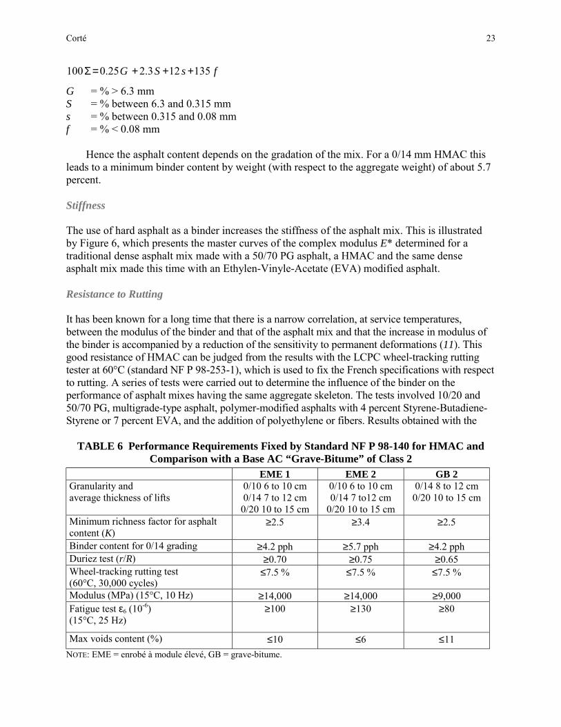
Table 6 summarizes the performance requirements fixed by standard NF P 98-140 for thetwo classes of HMAC and, by comparison, that of a traditional base AC (“grave-bitume” of class2 of French AFNOR standard NF P 98-138).
As seen from Table 6, for EME2 the requirement for the binder content is a minimumrichness factor K, of 3.4. This K factor is defined by the following equations:
5 ΣαTLK =
where
TL = binder content (ratio by weight of asphalt to aggregate)α = 2.65/Gse (Gse effective specific gravity of aggregate)

0
10
20
30
40
50
60
70
80
90
1000.01 0.1 1 10 100
0,08
2
6,3
14
0.315
FIGURE 4 Sieve analysis = typical grading for a 10/14mm HMAC with6.2 percent asphalt content.
0
5
10
15
20
25
1 10 100 1000
HMAC 0/146.2%
AC 0/145.4%
FIGURE 5 Gyratory shear compaction tests: comparison between HMAC and atraditional base asphalt concrete.
Size of Sieve (mm)
Perc
ent P
assi
ngPe
rcen
t Air
Void
s C
onte
nt
Corté 23
fsSG 135123.225.0100 +++=Σ
G = % > 6.3 mmS = % between 6.3 and 0.315 mms = % between 0.315 and 0.08 mmf = % < 0.08 mm
Hence the asphalt content depends on the gradation of the mix. For a 0/14 mm HMAC thisleads to a minimum binder content by weight (with respect to the aggregate weight) of about 5.7percent.
Stiffness
The use of hard asphalt as a binder increases the stiffness of the asphalt mix. This is illustratedby Figure 6, which presents the master curves of the complex modulus E* determined for atraditional dense asphalt mix made with a 50/70 PG asphalt, a HMAC and the same denseasphalt mix made this time with an Ethylen-Vinyle-Acetate (EVA) modified asphalt.
Resistance to Rutting
It has been known for a long time that there is a narrow correlation, at service temperatures,between the modulus of the binder and that of the asphalt mix and that the increase in modulus ofthe binder is accompanied by a reduction of the sensitivity to permanent deformations (11). Thisgood resistance of HMAC can be judged from the results with the LCPC wheel-tracking ruttingtester at 60°C (standard NF P 98-253-1), which is used to fix the French specifications with respectto rutting. A series of tests were carried out to determine the influence of the binder on theperformance of asphalt mixes having the same aggregate skeleton. The tests involved 10/20 and50/70 PG, multigrade-type asphalt, polymer-modified asphalts with 4 percent Styrene-Butadiene-Styrene or 7 percent EVA, and the addition of polyethylene or fibers. Results obtained with the
TABLE 6 Performance Requirements Fixed by Standard NF P 98-140 for HMAC andComparison with a Base AC “Grave-Bitume” of Class 2
EME 1 EME 2 GB 2Granularity andaverage thickness of lifts
0/10 6 to 10 cm0/14 7 to 12 cm
0/20 10 to 15 cm
0/10 6 to 10 cm0/14 7 to12 cm
0/20 10 to 15 cm
0/14 8 to 12 cm0/20 10 to 15 cm
Minimum richness factor for asphaltcontent (K)
≥2.5 ≥3.4 ≥2.5
Binder content for 0/14 grading ≥4.2 pph ≥5.7 pph ≥4.2 pphDuriez test (r/R) ≥0.70 ≥0.75 ≥0.65Wheel-tracking rutting test(60°C, 30,000 cycles)
≤7.5 % ≤7.5 % ≤7.5 %
Modulus (MPa) (15°C, 10 Hz) ≥14,000 ≥14,000 ≥9,000Fatigue test ε6 (10-6)(15°C, 25 Hz)
≥100 ≥130 ≥80
Max voids content (%) ≤10 ≤6 ≤11NOTE: EME = enrobé à module élevé, GB = grave-bitume.

FIGURE 6 Complex modulus master curves on three different asphalt mixes(BBSG = Béton Bitumineaux Semi-Grenu).
0
2
4
6
8
10
12
14
16
10 100 1,000 10,000 100,000
Number of Cycles
Rut
Dep
th (p
erce
nt)
50/70
SBS
Multigrade 50/70
"10/20"
EVA
Waste PE
FIGURE 7 Wheel-tracking test results showing the influence of the asphalt binder on theresistance to rutting of similar AC mixes (PE = polyethylene).

Corté 25
FIGURE 8 View of LCPC’s accelerated pavement testing facility.
LCPC wheel-tracking rutting tester are shown in Figure 7. The assessments from these laboratorytests have been confirmed by experiments with LCPC’s accelerated loading test facility (Figure 8).These full-scale experiments confirmed the very good behavior of HMAC + VTAC in resistance torutting and in durability of surface macrotexture (12, 13).
Resistance to Fatigue
Resistance to fatigue cracking is assessed by the two-point bending test on trapezoidal sampleswith controlled displacement imposed at the top of the beam. The higher asphalt content togetherwith the lower air voids content in HMAC as compared to traditional base AC provide a betterresistance to fatigue as indicated by the increase in the strain for which failure as reached after106 cycles. The HMAC standard requires a minimum value of 130 10-6 for ε6 for EME2 when therequirement is only 80 10-6 with a traditional base such as AC GB2 (see Table 6). A typicalexample of fatigue curves is shown by Figure 9. The mean value of the slope of the fatigue curvefound over 16 different HMACs was –1/6 (with values ranging from a minimum of –1/7.5 to amaximum of –1/5.2). The mean value is –1/5 for traditional base AC.
Pavement Design with HMAC
The French pavement design method (4) can be described as a rational approach which makesuse of a mechanical model together with the results of complex modulus and of two-pointbending fatigue tests. Taking into account certain simplifications of the model and theapproximate character of the fatigue laboratory test, the calculation of the working strains εt,ad(N)uses a shift factor kc which is derived from an adjustment between model predictions andmonitoring of in-service pavements.

26 Transportation Research Circular 503: Perpetual Bituminous Pavements
εt,ad(N) = ε6f(N)kc
where N stands for the number of load cycles to failure and ε6 is the applied strain at failure aftera million cycles in the two-point bending fatigue test.
For the traditional techniques, which have been under a long period of observation (i.e.,traditional pavement structures have sustained traffic for at least as long as the project servicelife), the shift factor was determined by consideration of a representative set of monitoredpavements. In the case of the introduction of a new technique like HMAC, design of suchpavements was made possible by using the results of accelerated loading tests. To this end,LCPC carried out a series of three experiments between 1990 and 1994 in cooperation with thetoll-motorways companies association. Each trial ring comprised four relatively thin asphalticbase layers (8 to 12 cm) resting on an untreated subbase. The results of these experiments(development of cracking versus the number of load cycles) were analyzed in a manner relatingthe behavior of the various sectors (14). From these experiments it was concluded that a lowershift factor should be used for HMAC than for pavements with traditional base AC (respectively1 and 1.3). However, because of the large difference in fatigue resistance, the working strain ofHMAC will still be larger. Combining kc and ε6 values from Table 6 gives for traditional base;AC GB2, εt,ad(N) = 104f(N); and for HMAC, εt,ad(N) = 130f(N).
1.0E+04
1.0E+05
1.0E+06
1.0E+07
1.0E-05 1.0E-04 1.0E-03
HMAC 1
HMAC 2
Num
ber o
f Cyc
les
Strain
AC
FIGURE 9 Two-point bending fatigue tests (one traditional base AC, two HMACshaving the same composition but different hard asphalt).

Corté 27
Illustration of the Possible Economic Gain with the Use of HMAC
The potential saving in the cost of a new pavement when using HMAC as compared to atraditional base concrete solution, can be illustrated by the following examples.
The first one is taken from the 1997 SCETAUROUTE’s catalogue. Table 7 presents acomparison for flexible pavements between a HMAC solution as a base layer and a traditionalbase AC. With the HMAC solution, the reduction in thickness represents 33 percent of the totalthickness of the asphaltic layers. If one considers now the asphalt quantities, because of thehigher binder content and the lower voids content of the HMAC, the difference between the twosolutions is reduced to approximately 24 percent.
The second example presented in Table 8 is related to full-depth asphalt pavements; it is takenfrom the 1998 French Road Directorate catalogue (9). Here the reduction in total thickness of thepavement is 25 percent, which represents about the same reduction in the quantity of aggregate; thereduction in the asphalt quantity is only 4.5 percent. The French Road Administration has preferredto adopt a binder layer to provide protection to the HMAC base course.
Assessment of Performance of HMAC Pavements
In 1997, an assessment of the performance of HMAC pavements built since the beginning of the1980s was published (15). This report covered the use of over 10 million tons of asphalt mix at 47sites, with pavements from 2 to 14 years old. The conclusions can be summarized as follows:
• For pavements between 2 and 6 years of age, there were no or only minor degradations,• For pavements between 6 and 10 years old, the percentage of cases presenting cracks grew
but the gravity of cracking was low to moderate,• For the oldest sites, the cracking was similarly moderate and did not require maintenance.
TABLE 7 Comparison Between HMAC and Traditional AC Solution forFlexible Pavements (1997 SCETAUROUTE’s Manual)
Flexible pavementTraffic: 600 HV/day, 4% increase/year, 15-year design
Subgrade modulus: 120 MPaTraditional AC solution HMAC solution
Wearing course: 2.5 cm BBTMBinder course: 6 cm BBLBase course: 13 cm GB3Subbase: 20 cm unbound gravel
Wearing course: 2.5 cm BBTMBase course: 12 cm EME2Subbase: 20 cm unbound gravel
Difference in thickness ofasphalt layers
7 cm (33%)
Difference in asphaltquantity
–24%
Difference in aggregate –33%BBTM: béton bitumineux très mince (VTAC)BBL: béton bitumineux de liaison (AC for binder layers)GB3: grave-bitume class3 (base AC)
EME2: enrobé à module élevé class 2 (HMAC for base layers)

28 Transportation Research Circular 503: Perpetual Bituminous Pavements
TABLE 8 Comparison of HMAC and Traditional AC Solution forFull-Depth Asphalt Pavement (1998 Road Directorate’s Catalogue)
Full-depth asphalt pavementTraffic: 20 million ESALs (130 kN)
Subgrade modulus: 120 MPaTraditional AC solution HMAC solution
Wearing course: 2.5 cm BBTMBinder course: 6 cm BBLBase course: 14 cm GB2Subbase: 14 cm GB2
Wearing course: 2.5 cm BBTMBinder course: 6 cm BBMEBase course: 9 cm EME2Subbase: 10 cm EME2
Difference in thickness of asphaltlayers
–9 cm (25%)
Difference in asphalt quantity –4.5%Difference in aggregate –24%
BBTM = béton bitumineax trés mince (VTAC)BBL = béton bitumineax de liaison (AC for binder layers)GB2 = grave bitume class 2 (traditional AC for base layers)EME2 = enrobé à module élevé class 2 (HMAC for base layers)BBME = béton bitumineux à module élevé (HMAC for binder layer)
Transverse cracks were found in two cases only, which shows that thermal cracking is, inthe French climatic context, a marginal phenomenon with these hard asphalts used in basecourse.
Low-Temperature Cracking
It is interesting to report here the extreme case of a trial section with a high-modulus AC made with avery hard asphalt. Initial characteristics were a penetration of 5/10 mm, a R&B softening point of88°C which led to a Young modulus for the HMAC of 21,600 MPa (direct tension test at 15°C and0.02 s). Tests on the recovered binder from a core taken from the pavement gave a softening pointof 93.5°C, and BBR’s temperatures Tm = 0.300 = +1.7°C and TG = 300 = –5.7°C (Tm is thetemperature when the slope m of the creep curve = 0.300; TG is the temperature when thesheer modulus G = 300 MPa). Cracking was observed after the first winter, with minimumrecorded temperatures of –10°C to –13°C.
HMAC for Surface Courses
The search for a solution for thick wearing courses, offering a good resistance to rutting, led tothe definition of another kind of high modulus AC, the “Bétons Bitumineux à Module Elevé,”BBME, codified since 1993 in French AFNOR standard NF P 98-141. These materials can alsobe used in binder courses, too.
These mixes generally have a continuous grading of 0/10 or 0/14. The minimum richnessfactor for the 0/10 mixes is 3.5, which corresponds to an asphalt content of the order of 5.6percent (by weight of aggregate) for aggregate with a density equal to 2.75.
The performance requirement for resistance to rutting is, in the case of heavy traffic, less than5 percent rutting after 30,000 cycles for wearing courses and less that 7.5 percent rutting after30,000 cycles for binder courses when the wearing course thickness is less than 5 cm.
The use of hard asphalt in the wearing course, which is the layer most exposed to

Corté 29
temperature variations and thermal shocks, should be considered cautiously because of the risksof low-temperature cracking or thermal fatigue. In order to limit this risk, a proposal has beenmade to improve the performance of hard asphalt at low temperature by a modification withpolymers. Table 9 presents the characteristics at low temperature of a plain 20/30 PG asphalt andof a hard asphalt modified by reticulation with a styrene-butadiene polymer. This productcurrently is in an experimental phase.
CONCLUSIONS
Hard asphalts, produced in France for nearly 20 years, have offered for the French climaticcontext very interesting technical solutions for rutting mitigation of asphalt pavements and forconstruction of stiff asphaltic base layers. Field performance has indicated no susceptibility tolow temperature or thermal fatigue cracking. On the contrary, poor performance had beenobserved in the past with asphalts produced by air blowing; the search for very high IP values bymeans of air blowing is detrimental to durability.
The mechanical properties of the hard asphalts are strongly dependent on manufacturingprocess because this directly influences the composition and the colloidal structure of theasphalts. The rheological tests showed in particular that the results (modulus, phase angle) canvary within a broad interval for asphalts having the same PG at 25°C. This can result insignificant differences in behavior at low temperature. Research appears to be still necessary,however, to better assess behavior at failure in order to identify the predominant factors linked tothe composition of these asphalts.
To benefit from the qualities of these hard asphalts, it is necessary to have an adequatedesign for the mix. This cannot just be a simple substitution of the binder. It is worthwhilestressing that, in the concept of HMAC developed in France, these base materials are designed
TABLE 9 Low Temperature Characteristics of Plain 20/30 Asphalt andStyrene-Butadiene–Reticulated Hard Asphalt
SB ReticulatedHard Asphalt
20/30 Plain Asphalt
Penetration (0.1 mm) at 25°C 27 25Fraass temperature (°C) –15 –10Direct tensile test (5°C, 100 mm/min)Strain at failure (%)Energy at 400 percent strain (J/cm2) at failure (J/cm2)
600
2337
fragile
Temperature G´´ (°C) (5 Hz) max –7 –1G* (MPa) (–10°C; 5 Hz) 355 463Phase angle (°) (–10°C; 5 Hz) 9.6 6.3Temperature G* (°C) (7.8 Hz) = 133.3 MPa 5.5 10

30 Transportation Research Circular 503: Perpetual Bituminous Pavements
with a higher binder content and a lower air voids content. Such provisions are intended tocompensate for problems with fatigue, the lower capacity of the hard-grade asphalts for healingas compared to the softer traditional grades.
Hard asphalts have mainly been used in base and binder courses with a surfacing whichensures a certain thermal protection. There is much less experience with HMAC in thick wearingcourses, and questions remain with respect to the behavior at low temperature. A solution may bein a complementary modification with polymers or in multigrade-type asphalts.
REFERENCES
1. Sauterey, R. Evolution de la consommation des bitumes pour enrobage à chaud. Bulletin deLiaison des Laboratoires des Ponts et Chaussées, No. 68, Nov.–Dec. 1973, p.16.
2. Simoncelli, J.-P., R. Chanut, et al. Comportement d’une couche bitumineuse épaisse soustrafic lourd, lent et canalisé. Bulletin de Liaison des Laboratoires des Ponts et Chaussées,No. 47, Sept.–Oct. 1970, pp.45–54.
3. Bitume Actualités. Dossier bitume, No. 91, June 1990.4. Conception et dimensionnement des structures de chaussées. Guide technique
LCPC/SETRA. Dec. 1994.5. Glita, S., and J. Conan. Analyse rhéologique de 7 bitumes durs 10/20. Congrès Eurasphalt—
Eurobitume, E&E 5.110, Strasbourg, Germany, 1996.6. Groupe National Bitume. Etude de la fissuration par le haut des bétons bitumineux. Rapport
CR 22, Etudes et Recherches des Laboratoires des Ponts et Chaussées, Oct. 1999.7. Langumier, G. Nouvelles possibilités en construction routière; GBTHP un mélange
bitumineux optimisé. Revue générale des routes et aérodromes, No. 612, pp 47–52.8. Manuel de conception des chaussées d'autoroutes. 3rd Ed. SCETAUROUTE Direction
Technique, March 1994.9. Catalogue des structures types de chaussées neuves de la Direction des routes.
LCPC/SETRA, Sept. 1998.10. Enrobés hydrocarbonés. Couches d'assises: Enrobés à module élevé. Norme française NF P
98-140, Oct. 1992.11. Brûlé, B., and J.-F. Corté. Rapport général. Session V. Congrès Eurasphalt—Eurobitume,
E&E 5.110, Strasbourg, Germany, 1996.12. Corté, J.-F., Y. Brosseaud, J. -P. Simoncelli, and G. Caroff. Investigation of Rutting of
Asphalt Surface Layers: Influence of Binder and Axle Loading Configuration.Transportation Research Record 1436, TRB, National Research Council, Washington, D. C.,1994, pp. 28-37.
13. Corté, J.-F., Y. Brosseaud, J.-P. Kerzreho, and A. Spernol. Study of Rutting on the WearingCourses of the LCPC Test Track, Vol. 2. 8th International Conference on Asphalt Pavements,Seattle, Wash., Aug. 10–14, 1997, pp. 1555-1568.
14. De la Roche, C., J.-F. Corté, J. C. Gramsammer, H. Odéon, L. Tiret, and G. Caroff. Etude dela fatigue des enrobés bitumineux à l’aide du manège de fatigue du LCPC. Revue généraledes routes et aérodromes, No. 716, 1994, pp. 62-74.
15. Les enrobés à module élevé. Note d'information du SETRA, No. 96, April 1997.

Corté 31
ADDITIONAL RESOURCES
Corté, J.-F., and J.-P. Michaut. Le développement d’une innovation : les enrobés à module élevé.AIPCR. Contribution à la Question IV, XX Congrès Mondial de la Route–Montréal, Sept. 1995.
Marciano, Y. Comportement à froid de bitumes durs. Rapport CR 24, Etudes et Recherches desLaboratoires des Ponts et Chaussées, Jan. 2000.

32
Design and Assessment of Long-Life Flexible Pavements
MICHAEL NUNNBRIAN W. FERNE
Transport Research LaboratoryUnited Kingdom
Improved strategies for design and condition assessment are required for flexible pavements, whichcarry the heaviest volumes of traffic, to decrease the need for maintenance and thereby cause lessdisruption to the road user. The current philosophy and criteria for design are reviewed, andinformation that has been collected since the last revision of standards in 1984 on the performance ofroads is considered. Results demonstrate that the deterioration of thick, well-constructed, fully flexiblepavements is not structural and that deterioration generally starts at the surface in the form ofcracking and rutting. The evidence suggests that fatigue and structural deformation originating deepwithin the pavement structure are not the prevalent modes of deterioration. It also shows that changesthat occur to the structural properties of the bituminous materials over the life of the road are crucialto the understanding of its behaviour. They imply that a road built above a minimum strength willremain structurally serviceable for a considerable period, provided an appropriate conditionassessment strategy is adopted to enable nonstructural deterioration, in the form of cracks and surfacedeformation, to be detected and remedied before it can have a serious impact on the structuralintegrity of the road.
he current pavement design method used in the United Kingdom for fully flexible pavementswas established by considering the performance of a wide range of experimental pavements
that formed part of the trunk road network (1). The method developed was based on theinterpretation of the structural performance of these roads in terms of theoretical design concepts.
A design life of 40 years was advocated, which was achieved by strengthening the road afterabout 20 years. Calculation of the costs of flexible roads over 40 years, taking into accountvariability of pavement performance, cost of traffic delays, and other costs associated withstrengthening, showed this to be the optimum design strategy. Since this method was introduced,traffic levels and the consequent disruption at roadworks has continued to increase (Figure 1).Economic considerations indicate that it is now cost-effective to increase the design life of veryheavily trafficked routes to at least 40 years, without the requirement for structural strengthening, inorder to reduce future maintenance and the associated traffic delay costs.
In addition, more knowledge has become available, over the last 10 years, on the performanceof heavily trafficked roads. This has indicated that deterioration, as either cracking or deformation,is far more likely to be found in the surfacing than deeper in the pavement structure; this evidence isin conflict with conventional theory. Also, it was found that the great majority of the thickpavements examined have maintained their strength or become stronger over time, rather thangradually weakening with trafficking as assumed in the current pavement assessment method basedon deflection measurements.
T

Nunn and Ferne 33
FIGURE 1 Disruption to road users on heavily trafficked roads.
This paper reviews design concepts and draws together up-to-date information from full-scaleexperimental pavements, studies of deterioration mechanisms on the road network, long-termdeflection monitoring of motorways, and condition assessment reports prepared to aid the design ofstructural maintenance. All of this information is required to produce a design method and strategyfor condition assessment for roads expected to last at least 40 years without the need for structuralmaintenance (2). These roads are described as long-life roads. The help of the Highways Agency, inallowing information to be used from extensive research programmes that the Transport ResearchLaboratory (TRL) has undertaken on behalf of the Highways Agency over many years, is gratefullyacknowledged.
PAVEMENT PERFORMANCE
Current U.K. pavement design for fully flexible pavements is based on an interpretation of theobserved performance of a number of experimental roads, which had carried up to 20 millionstandard axles (msa), using structural theory. Considerable extrapolation of the observedperformance trends was necessary to provide current designs for over 100 msa.
A staged construction is adopted for trunk roads in the United Kingdom. The road is initiallydesigned to reach an investigatory condition after about 20 years, which is considered to be the idealtiming to use. To use the existing strength of the road to good effect in designing a strengtheningoverlay to extend life for another 20 years. If the road passes beyond that condition, overlay isconsidered less effective and reconstruction is necessary. The investigatory condition can be related tothe transient deflection under a standard wheel load moving at creep speed. This deflection is believedto increase gradually with increasing traffic until the deflection and the level of rutting and crackingindicate the need for strengthening, as first described by Kennedy and Lister (3).
34 Transportation Research Circular 503: Perpetual Bituminous Pavements
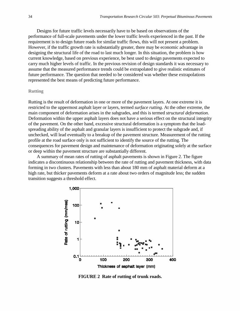
Designs for future traffic levels necessarily have to be based on observations of theperformance of full-scale pavements under the lower traffic levels experienced in the past. If therequirement is to design future roads for similar traffic flows, this will not present a problem.However, if the traffic growth rate is substantially greater, there may be economic advantage indesigning the structural life of the road to last much longer. In this situation, the problem is howcurrent knowledge, based on previous experience, be best used to design pavements expected tocarry much higher levels of traffic. In the previous revision of design standards it was necessary toassume that the measured performance trends could be extrapolated to give realistic estimates offuture performance. The question that needed to be considered was whether these extrapolationsrepresented the best means of predicting future performance.
Rutting
Rutting is the result of deformation in one or more of the pavement layers. At one extreme it isrestricted to the uppermost asphalt layer or layers, termed surface rutting. At the other extreme, themain component of deformation arises in the subgrades, and this is termed structural deformation.Deformation within the upper asphalt layers does not have a serious effect on the structural integrityof the pavement. On the other hand, excessive structural deformation is a symptom that the load-spreading ability of the asphalt and granular layers is insufficient to protect the subgrade and, ifunchecked, will lead eventually to a breakup of the pavement structure. Measurement of the ruttingprofile at the road surface only is not sufficient to identify the source of the rutting. Theconsequences for pavement design and maintenance of deformation originating solely at the surfaceor deep within the pavement structure are substantially different.
A summary of mean rates of rutting of asphalt pavements is shown in Figure 2. The figureindicates a discontinuous relationship between the rate of rutting and pavement thickness, with dataforming in two clusters. Pavements with less than about 180 mm of asphalt material deform at ahigh rate, but thicker pavements deform at a rate about two orders of magnitude less; the suddentransition suggests a threshold effect.
FIGURE 2 Rate of rutting of trunk roads.

Nunn and Ferne 35
Above about 180 mm there is no correlation between the rate of rutting and pavementthickness. The results suggest that for these thicker pavements nearly all the rutting is due todeformation within the upper layers and that the traffic-induced strains in the subgrade are too lowto cause structural deformation. It is apparent that below thicknesses of about 180 mm, the muchhigher traffic-induced subgrade strains have a much greater effect.
Fatigue
The road base is the most important structural layer of the road. All modern analytical designmethods for flexible pavements include a criterion, based on laboratory studies, to guard against thepossibility of fatigue cracks initiating at the underside of the road base. These methods considerfatigue cracking, caused by repeated traffic loading, to be the major component of structuraldeterioration. Investigation of the road base fatigue mechanism in full-scale pavements is muchmore difficult than in the laboratory and it has been noted that, although surface cracking is oftenobserved, there is little evidence of fatigue cracking in the road base of in-service asphaltpavements in the United Kingdom (4, 5). Furthermore, it is known that the stiffness of asphalt roadbase increases with time, and this influences its fatigue resistance. However, this effect has receivedlittle attention in the past in relation to road base performance.
The absence of positive evidence of fatigue prompted TRL to initiate an investigation into theresidual fatigue life of asphalt road bases from heavily and lightly trafficked areas of the samemotorways. The aim was to compare the structural properties of samples of road base measured inthe laboratory with the overall condition of the pavements from which they were extracted. Thiswork (6, 7) helped to improve basic understanding of the mechanisms of structural deterioration.
Investigation of Roadbase Fatigue in U.K. Motorways
Short sections of four motorways (Table 1), representing a range of age and traffic loading, wereselected for detailed investigation. All the pavements examined carried more traffic than they wereoriginally designed to carry.
Cores were cut to enable the structural properties of materials that had been subjected to heavycommercial traffic in the wheelpath of Lane 1 to be compared to the lightly trafficked material ofthe same age and nominal composition from between the wheelpaths in Lane 3. A comparison ofthe laboratory-measured residual fatigue life of the lower road base is shown in Table 2.
TABLE 1 Pavements Investigated
Site Age(years)
Cumulative traffic(msa)
Road Base Thickness of asphalt(mm)
M4M5M1M62
11192321
22667157
HRADBMDBMDBM
230300350300

36 Transportation Research Circular 503: Perpetual Bituminous Pavements
TABLE 2 Comparison of Fatigue Life of Road BaseSite Lane Number of Tests Relative Fatigue Life of Road BaseM4 1
38076
1.01.5
M5 13
3533
1.00.7
M1 13
1911
1.01.6
M62 13
2831
1.00.4
Mean 13
162151
1.01.1
If traffic was responsible for weakening the road base, the residual fatigue life of road basematerial subjected to heavy traffic, in Lane 1, would be significantly lower than that of the lightlytrafficked material, between the wheelpaths of Lane 3. Table 2 shows that there was no consistentdifference between these measured residual fatigue lives. Most of the difference was accounted forby variations of binder hardness and binder content between the samples extracted from the twolanes. When these factors were taken into account, none of the differences were statisticallysignificant.
All the material tested had a residual fatigue life lower than that of new material. Althoughtraffic loading could not account for this reduction, age will have been an important factor. It is wellestablished that the aging of binders results in an increase in stiffness and a reduction in residualfatigue life of the road base. These changes are unlikely to result in fatigue cracking of thepavement. Calculations using the relationships developed in this study show that the increase inelastic stiffness with age produces a reduction in the traffic-induced, tensile strain responsible forfatigue at the underside of the road base. This reduction more than compensates for any reduction inthe laboratory fatigue life of the aged road base. The net effect is that the predicted fatigue life ofthe road increases with age. This would explain why no positive evidence of fatigue was found.
Structural Assessments
Structural assessments of asphalt roads have failed to detect any evidence of road base fatiguedamage. There are no authoritative reports of cracks propagating upwards. In older roads, apartfrom the absence of road base cracks, the measured elastic stiffness modulus of road base materialextracted from the road is usually substantially higher than that expected for new construction. Thisis indicative that fatigue weakening is not occurring.
In a study carried out by the Road and Hydraulic Engineering Division of the Dutch Ministryof Transport, 176 sections of flexible pavement were examined in order to verify their pavementdesign method (8). This study revealed that in pavements with an asphalt pavement thicknessgreater than 160 mm, cracks initiated at the surface and generally did not penetrate the full depth ofthe asphalt. In thinner pavements, where the asphalt was fully cracked, a structural analysisindicated that the cracks also initiated at the surface and propagated downwards. The overall

Nunn and Ferne 37
conclusion of this work was that, conventional fatigue will rarely or never be the predominantfailure mechanism, but surface cracking will be the main cause of structural distress.
Surface Cracking
Cracking observed at the surface of thick, mature, flexible pavements is relatively common. Themost usual form is longitudinal cracks in the wheel tracks. This has often been regarded as evidenceof conventional fatigue in which cracks have initiated at the bottom of the road base and thenpropagated to the surface. However, where this cracking has been investigated by cutting cores, ithas invariably been found that the propagation is downwards rather than upwards.
Longitudinal surface cracks have been observed at 10 sites investigated by TRL. At these sites,provided the crack had not propagated into the road base, there was no observable or measurabledamage to the road base directly beneath the cracks. An example of longitudinal cracking in the M1site is shown in Figure 3.
Surface cracking is not always longitudinal. At other sites transverse cracks occurred in alllanes of each carriageway, and they were not confined to wheel tracks. As with longitudinalcracking, transverse cracks generally penetrated only up to 100 mm into the surfacing.
FIGURE 3a Longitudinal cracking in the near-side wheelpath of the M1 site.

38 Transportation Research Circular 503: Perpetual Bituminous Pavements
FIGURE 3b Longitudinal cracking in the near-side wheelpath of the M1 site.
The mechanism of surface cracking is complex, and there is no satisfactory explanation of thisphenomenon. Calculation of the traffic-induced stresses at the pavement surface is complicatedbecause the vertical contact stresses are nonuniform and radial horizontal forces are present.Consequently, significant horizontal tensile stresses can be generated at the surface of thepavement.
Thermally generated stresses will also contribute toward the initiation and propagation ofsurface cracks. This is especially so for transverse cracking in which thermal stresses are likely tobe the principal cause of the tensile condition required for crack initiation. Age hardening of thebinder in the wearing course, especially the top few millimeters, will also play a part, withhardening over time progressively reducing the ability of the wearing course to withstand thethermal and traffic-generated stresses at the surface.
Curing of Asphalt
It has long been known that the bitumen in pavement layers stiffens with time. Whereas a gradualhardening of the main structural layers appears to be beneficial, and is more accurately described ascuring, excessive ageing of the wearing course can lead to cracks initiating at the surface.
During the mixing and laying process, the penetration of the bitumen in standard densebitumen macadam (DBM) typically drops from an initial nominal value of 100 to about 70. Insubsequent service, further reduction takes place resulting in values often as low as 20 after 20years. Chaddock and Pledge (9) demonstrated, in test pavements, that the curing behaviour wasvariable and that the stiffness of DBM road base could change by over 100 percent during the firstyear in service.
In addition to the test pavements, data on the curing of road base material from a large numberof in-service roads has been collected by TRL. These data include the measured properties of therecovered binder and stiffnesses of materials from pavements of different ages. Figure 4 shows thevariation of penetration of the recovered binder, with time, for DBM road base manufactured with a
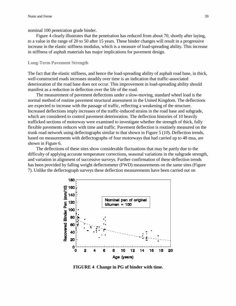
Nunn and Ferne 39
nominal 100 penetration grade binder.Figure 4 clearly illustrates that the penetration has reduced from about 70, shortly after laying,
to a value in the range of 20 to 50 after 15 years. These binder changes will result in a progressiveincrease in the elastic stiffness modulus, which is a measure of load-spreading ability. This increasein stiffness of asphalt materials has major implications for pavement design.
Long-Term Pavement Strength
The fact that the elastic stiffness, and hence the load-spreading ability of asphalt road base, in thick,well-constructed roads increases steadily over time is an indication that traffic-associateddeterioration of the road base does not occur. This improvement in load-spreading ability shouldmanifest as a reduction in deflection over the life of the road.
The measurement of pavement deflections under a slow-moving, standard wheel load is thenormal method of routine pavement structural assessment in the United Kingdom. The deflectionsare expected to increase with the passage of traffic, reflecting a weakening of the structure.Increased deflections imply increases of the traffic-induced strains in the road base and subgrade,which are considered to control pavement deterioration. The deflection histories of 10 heavilytrafficked sections of motorway were examined to investigate whether the strength of thick, fullyflexible pavements reduces with time and traffic. Pavement deflection is routinely measured on thetrunk road network using deflectographs similar to that shown in Figure 5 (10). Deflection trends,based on measurements with deflectographs of four motorways that had carried up to 48 msa, areshown in Figure 6.
The deflections of these sites show considerable fluctuations that may be partly due to thedifficulty of applying accurate temperature corrections, seasonal variations in the subgrade strength,and variation in alignment of successive surveys. Further confirmation of these deflection trendshas been provided by falling weight deflectometer (FWD) measurements on the same sites (Figure7). Unlike the deflectograph surveys these deflection measurements have been carried out on
FIGURE 4 Change in PG of binder with time.

40 Transportation Research Circular 503: Perpetual Bituminous Pavements
FIGURE 5 Deflectograph survey in progress.
FIGURE 6 Deflection histories of in-service motorways—deflectograph measurements.
exactly the same points each year. Examples of trends from two of the sites over a 13-year periodare given in Figure 8.
With one exception, which shows no decisive trend either way, all the sections show a trend ofsteady or decreasing deflection with age and traffic. These decreases imply that the overall stiffnessesof the pavements are increasing over time and that any traffic-related deterioration is more than offsetby curing of the road base or strengthening of the foundation. For whatever reason, the road isbecoming stiffer with time, and, hence, the traffic-induced stresses and strains in the road base and thesubgrade, which are considered to be responsible for structural deterioration, are decreasing.

FIGURE 7 FWD carrying out measurements.
FIGURE 8 Deflection histories of in-service motorways—FWD measurements.

42 Transportation Research Circular 503: Perpetual Bituminous Pavements
CONSIDERATIONS FOR LONG-LIFE PAVEMENT DESIGN
The conclusion from the review of information on the performance of flexible roads in the UnitedKingdom is that, above a threshold strength, the road will remain structurally serviceable for aconsiderable period provided that nonstructural deterioration, in the form of surface-initiated cracksand deformation, is detected and remedied before it can have a serious impact on the integrity of theroad. To achieve a long life it is also necessary for the road to be well constructed with good qualityasphalt and a good foundation so that deterioration does not result from construction or materialinadequacies.
Threshold Strength, Curing, and Traffic Flow
Curing implies that the road is most vulnerable to damage from traffic when it is first laid, before itsstructural properties have had time to improve. Provided that the road is built strong enoughinitially, so that its main structural layers are not weakened by traffic loading, curing willprogressively improve the load-spreading ability of these layers and make the road progressivelyless vulnerable to traffic-induced structural damage. This type of behavior implies that there is aminimum threshold strength above which the pavement should have a very long but indeterminatestructural life. It is therefore reasonable to assume that the initial strength of the road should be amajor factor in determining its future life.
Roads constructed to meet the demands of present-day traffic levels, which may be 10 or 20times higher than those encountered on many of the older in-service roads, will need to be initiallystronger to avoid excessive deterioration in their early life. A conservative calculation indicates thata road constructed with a thickness of more than 260 mm of asphalt would have a long butindeterminate life for traffic of up to 5 msa per year and that 270 mm would be sufficient for anytraffic loading. This higher thickness would ensure long life, even if curing did not take place,provided that the effective thickness of the asphalt layer was not reduced by deterioration due tocracking.
Surface Cracking
Surface cracking, in a road that is built just above the minimum strength required for long life, mayweaken the road and accelerate the deterioration. To prevent this from occurring, it will benecessary to adopt conservative designs to enable the road to withstand some surface cracks.Timely remedial action should be taken before these cracks can have a severe structural impact onthe road; however, cracks may propagate up to 100 mm into the road before this action is taken.The most conservative assumption is to assume that the material down to the depth of the crackpenetration does not contribute to load spreading. This would imply that a road constructed with atotal of 370 mm of asphalt material would be able to tolerate a surface-initiated crack propagating100 mm into the road even if the effect of curing was very small.
Provision for Future Changes in Vehicle Characteristics
The current legal maximum axle load is 10.5 tonnes, and this was increased to 11.5 tonnes in 1999.An increase in the thickness of the bound layer of 20 mm would be more than sufficient to provideextra load-spreading ability to compensate for this increase in legal maximum axle load.

Nunn and Ferne 43
Risk of Premature Failure
The addition of the conservative estimates to allow for the factors discussed above suggests that apavement consisting of 390 mm of asphalt material is sufficient for a long-life road. Thissummation introduces further conservatism since, for example, surface cracks, if they occur at all,will normally appear several years after the road is laid. By this time the road base will have cured,and the remaining thickness will be well above the threshold strength for a long-life road. Apavement of this thickness will be able to tolerate opening traffic well in excess of 5 msa per yeareven if the asphalt in the main structural layers does not cure.
A practical way forward is to use the existing design curves for traffic levels up to the level ofthe threshold strength and then regard the design as long life, with no additional thickness requiredto provide longer life. Figure 9 illustrates possible design curves using the three standard road basematerials that are characterised by three different levels of elastic stiffness or load-spreading ability.
These designs will have built-in conservatism, but some conservatism can be justified,considering the economic importance of these roads. A thickness of less than 200 mm for theasphalt paving is not recommended even for lightly trafficked roads that are required to endure for40 years. Thin roads may be at risk of structural deformation and rapid propagation of surface-initiated cracks through the full thickness of asphalt.
500
400
300
200
100
01 10 100 1,000
Thic
knes
s of
Asp
halt
Laye
rs (m
m)
Design Life (msa)
DBM
DBM50HDM
FIGURE 9 Design curve to include long-life pavements.
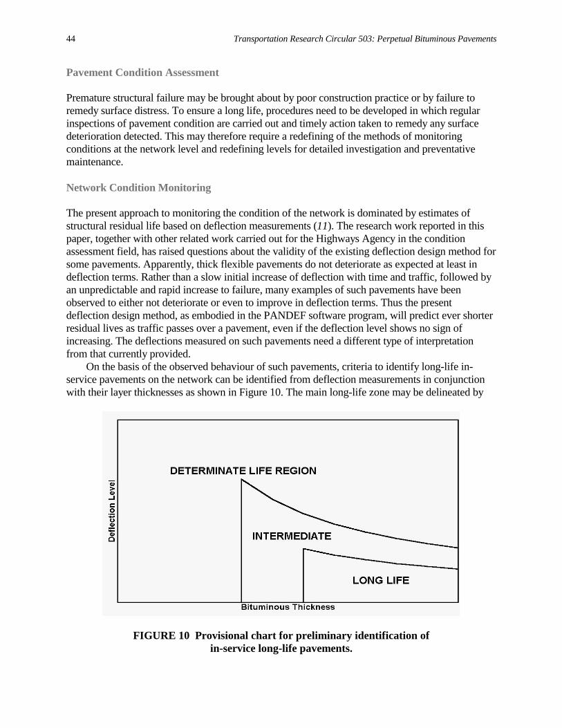
44 Transportation Research Circular 503: Perpetual Bituminous Pavements
Pavement Condition Assessment
Premature structural failure may be brought about by poor construction practice or by failure toremedy surface distress. To ensure a long life, procedures need to be developed in which regularinspections of pavement condition are carried out and timely action taken to remedy any surfacedeterioration detected. This may therefore require a redefining of the methods of monitoringconditions at the network level and redefining levels for detailed investigation and preventativemaintenance.
Network Condition Monitoring
The present approach to monitoring the condition of the network is dominated by estimates ofstructural residual life based on deflection measurements (11). The research work reported in thispaper, together with other related work carried out for the Highways Agency in the conditionassessment field, has raised questions about the validity of the existing deflection design method forsome pavements. Apparently, thick flexible pavements do not deteriorate as expected at least indeflection terms. Rather than a slow initial increase of deflection with time and traffic, followed byan unpredictable and rapid increase to failure, many examples of such pavements have beenobserved to either not deteriorate or even to improve in deflection terms. Thus the presentdeflection design method, as embodied in the PANDEF software program, will predict ever shorterresidual lives as traffic passes over a pavement, even if the deflection level shows no sign ofincreasing. The deflections measured on such pavements need a different type of interpretationfrom that currently provided.
On the basis of the observed behaviour of such pavements, criteria to identify long-life in-service pavements on the network can be identified from deflection measurements in conjunctionwith their layer thicknesses as shown in Figure 10. The main long-life zone may be delineated by
FIGURE 10 Provisional chart for preliminary identification ofin-service long-life pavements.
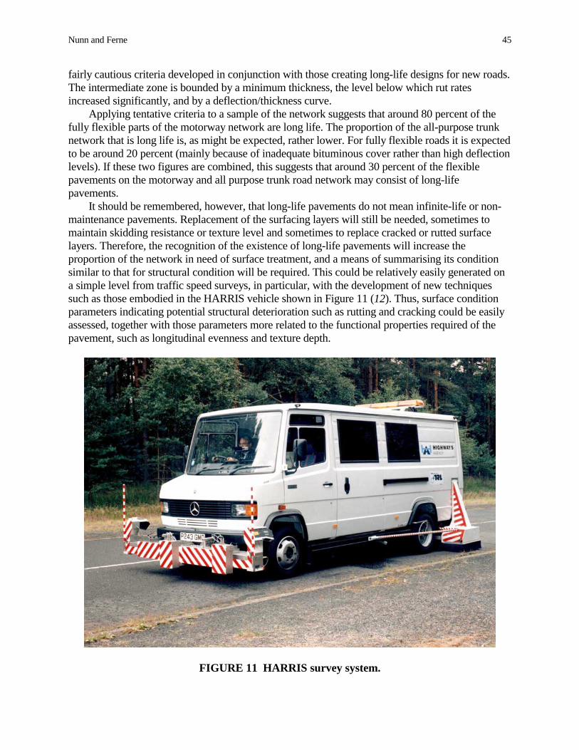
Nunn and Ferne 45
fairly cautious criteria developed in conjunction with those creating long-life designs for new roads.The intermediate zone is bounded by a minimum thickness, the level below which rut ratesincreased significantly, and by a deflection/thickness curve.
Applying tentative criteria to a sample of the network suggests that around 80 percent of thefully flexible parts of the motorway network are long life. The proportion of the all-purpose trunknetwork that is long life is, as might be expected, rather lower. For fully flexible roads it is expectedto be around 20 percent (mainly because of inadequate bituminous cover rather than high deflectionlevels). If these two figures are combined, this suggests that around 30 percent of the flexiblepavements on the motorway and all purpose trunk road network may consist of long-lifepavements.
It should be remembered, however, that long-life pavements do not mean infinite-life or non-maintenance pavements. Replacement of the surfacing layers will still be needed, sometimes tomaintain skidding resistance or texture level and sometimes to replace cracked or rutted surfacelayers. Therefore, the recognition of the existence of long-life pavements will increase theproportion of the network in need of surface treatment, and a means of summarising its conditionsimilar to that for structural condition will be required. This could be relatively easily generated ona simple level from traffic speed surveys, in particular, with the development of new techniquessuch as those embodied in the HARRIS vehicle shown in Figure 11 (12). Thus, surface conditionparameters indicating potential structural deterioration such as rutting and cracking could be easilyassessed, together with those parameters more related to the functional properties required of thepavement, such as longitudinal evenness and texture depth.
FIGURE 11 HARRIS survey system.

46 Transportation Research Circular 503: Perpetual Bituminous Pavements
Scheme Selection
Current assessment procedures for assessing the structural needs of road pavements and schemeselection are set out in Volume 7 of the English Highways Agency’s Design Manual for Roads andBridges (13). The main features are illustrated in the flowchart in Figure 12. Although conditiondata are available from the High Speed Road Monitor (HRM) and CHART visual surveys, it is theresults from deflectograph surveys that most strongly influence maintenance decisions.
The studies developing the concepts for long-life pavements have shown that, in the vastmajority of cases on the trunk road network, the deterioration mechanisms encountered concerndefects originating and propagating from the surface of the pavement downwards. This suggeststhat a more appropriate and reliable pavement assessment regime would be achieved by always firstconsidering surface condition before structural condition. A new approach could integrate existing
RESIDUALLIFE <=5YRS
NO
YES
SURFACEWEAR?
NO
STRUCTURALDETERIORATION
CONFIRMED?
INVESTIGATESURFACE
WEAR
NO
DESIGNSURFACE
TREATMENT
DESIGNSTRUCTURALTREATMENT
YES
INVESTIGATESTRUCTURE
ROUTINE HRM,CHART AND
DEFLECTOGRAPHSURVEYS
YES
FIGURE 12 Current structural assessment procedure (HRM = high-speed road monitor).

Nunn and Ferne 47
procedures for assessing surface and structural maintenance and assume that no maintenance of anykind is required unless there is evidence of wear on the road surface. Much more reliance would beplaced on the results of surface condition surveys that will, in future, mostly be carried out at trafficspeed with little traffic disruption. However, routine deflection surveys would need to continue tosupport network structural assessments and maintenance decisions for all types of pavements,particularly the thinner ones.
Project Level Investigations
The initial aim of project level investigations will be to determine how far the surface deteriorationextends into the pavement and, in particular, whether it is only in the surfacing. Details of the exactlocation and extent of rutting and pattern of cracking will be available from routine survey data.Cores taken on the cracks or at crack ends will determine the depth, direction and propagation ofcracks. These cores should penetrate at least halfway into the base on fully flexible pavements toensure that the full depth of cracking can be recorded. They will also provide evidence of whichlayers are affected by rutting and any loss of integrity of the materials, such as stripping of thebinder. In future, on the basis of earlier TRL research, it may be possible to use ground penetratingradar systems to monitor such penetration nondestructively (14). If the cracking is found topenetrate into the structural layers of the pavement, a conventional thorough structural investigationwill be necessary.
Treatment Selection
Acknowledgement of the existence of long-life pavements will, of course, affect the selection ofsuitable maintenance treatments. As was stated earlier, long-life pavements will not be of infinitelife. However, as long as the pavement has been well constructed and the foundations remainsound, no structural treatment such as overlays or reconstruction should be necessary. The surfacewill deteriorate as for determinate life pavements. Accumulated deformation will cause rutting,which will need to be treated by replacement or by thin overlay before it becomes a safety hazard.Cracking may initiate at the surface, which will need treating by replacement before it penetratesinto the structural components of the pavement. Skid resistance will deteriorate and initiate thenecessary remedial surface treatment. If structural deterioration has occurred, on a determinate-lifepavement, strengthening may need to be provided by overlays or reconstruction. However, it shouldbe noted that it may be that only thin overlays are necessary to convert a determinate-life pavementinto a long-life equivalent.
CONCLUDING REMARKS
This proposed design method suggests that, in future, the wearing course on fully flexiblepavements is likely to be replaced at intervals, whereas the underlying layers will be regarded aspermanent. Thus, maintenance costs would be generally limited to the wearing course to maintainsafety and comfort for the road user.
Pavement deterioration caused by cracks propagating downwards from the surface has receivedrelatively little attention from researchers. However, a better understanding of deteriorationmechanisms in general will result in improved materials and construction practices that prevent ordelay the onset of problems. The ultimate goal of pavement design is to develop a mechanistic

48 Transportation Research Circular 503: Perpetual Bituminous Pavements
method based on a fundamental understanding of the behaviour of road materials. Although thisgoal may be difficult to achieve, it should be pursued. A fully developed and validated analyticaldesign method would aid economic planning and provide insight into the consequences of futurechanges in materials or vehicle characteristics.
The relationships developed between design inputs and design thicknesses are based onhistorical evidence. Therefore, there is a need to continually monitor factors that may affectpavement performance. For the future there are many changes expected, such as heavier lorries, airsuspensions, increasing proportions of super-single tyres, and the development of innovativematerials and construction practices. All of these will need careful monitoring so that designs canbe adjusted as necessary to ensure that road pavements provide good value for money.
The overall conclusion is that well-constructed pavements built above a minimum strength arenot likely to exhibit structural damage when subjected to very high levels of commercial traffic fora very long time, provided that deterioration originating in the asphalt surfacing as either rutting orsurface initiated cracking is detected and remedied before it has a serious impact on the structuralintegrity of the road.
Existence of long-life pavements has increased the importance of reliable methods ofassessment of surface condition, in particular the identification of surface cracks and their depth ofpropagation. The recent development of new traffic-speed equipment to identify surface cracksautomatically will help with this, but further techniques still need to be developed.
The maintenance of in-service long-life pavements should be relatively simple and low cost ifclose monitoring of surface condition is employed and any loss of surface integrity rapidly repaired.
ACKNOWLEDGMENTS
The research into the design of long-life pavements described in this paper was funded jointly bythe Highways Agency, Quarry Products Association, and the Refined Bitumen Association.Research into the assessment of long-life pavements is funded by the Highways Agency. The paperis published with the permission of these organizations.
REFERENCES
1. Powell, W. D., J. F. Potter, H. Mayhew, and M. E. Nunn. Design of Bituminous Roads. TRLReport LR 1132, Transport Research Laboratory, Crowthorne, U.K., 1984.
2. Nunn, M. E., A. Brown, D. Weston, and J. C. Nicholls. Design of Long-Life FlexiblePavements for Heavy Traffic. TRL Report 250, Transport Research Laboratory, Crowthorne,U.K., 1997.
3. Kennedy, C. K., and N. W. Lister. Prediction of Pavement Performance and the Design ofOverlays. Report LR 833, Transport and Road Research Laboratory, Crowthorne, U.K., 1978.
4. Goddard, R. T. N., and W. D. Powell. Assessing the Condition of Bituminous Roads. Journal ofthe Institution of Highways and Transportation, Vol. 34, No. 5, London, U.K., 1987, pp. 26–32.
5. Thrower, E. N. A Parametric Study of a Fatigue Prediction Model for Bituminous RoadPavements. TRL Report LR 892, Transport Research Laboratory, Crowthorne, U.K., 1979.
6. Wu, F. Assessment of Residual Life of Bituminous Layers for the Design of PavementStrengthening. Ph.D. thesis. University of Glamorgan, Wales, U.K., 1992.
7. Nunn, M. A Question of Fatigue? Symposium on Performance and Durability of BituminousMaterials, University of Leeds, U.K., 1994.

Nunn and Ferne 49
8. Schmorak, N., and A. Van Dommelen. Analysis of the Structural Behaviour of AsphaltConcrete Pavements in SHRP-NL Test Sections. International Conference on SHRP and TrafficSafety, Prague, Czechoslovakia, 1995.
9. Chaddock, B., and K. Pledge. Accelerated and Field Curing of Asphalt Road base. TRL ProjectReport PR87, Transport Research Laboratory, Crowthorne, U. K., 1994.
10. Ferne, B. W., and P. K. Roberts. Deflectograph—The Way Forward for Structural Assessment.Institution of Highways and Transportation, London, Oct. 1991, pp. 5–6.
11. Jordan, P. G., B. W. Ferne, and D. R. Cooper. An Integrated System for the Evaluation of RoadPavements. 6th International Conference on the Structural Design of Asphalt Pavements, AnnArbor, Mich., 1987.
12. Ferne, B. W., L. G. Hawker, and J. Pynn. A Practical System for Crack Image Collection andAutomatic Identification. 5th International Conference on the Bearing Capacity of Roads andAirfields, Trondheim, Norway, 1998.
13. Design Manual for Roads and Bridges. English Highways Agency, Norwich, U.K., 1974.14. Hawker, L. G., and B. W. Ferne. Routine Assessment of the English Trunk Road Network.
Proc., Alan Brant Memorial Workshop, Leamington Spa, U.K., April 1992, Institution ofHighways and Transportation, London, 1992.
50
Long-Life Rehabilitation Design and ConstructionI-710 Freeway, Long Beach, California
JIM ST. MARTINAsphalt Pavement Association, California
JOHN T. HARVEYFENELLA LONGEUL-BUM LEE
CARL L. MONISMITHPavement Research Center
University of California–Berkeley
KEVIN HERRITTCalifornia Department of Transportation
This paper briefly describes the methodologies used for the mix and structural pavement sectiondesigns for the rehabilitation of the Interstate 710 (I-710) freeway adjacent to the Port of LongBeach, California, which include asphalt concrete (AC) replacement structures in the vicinity ofthree overcrossings and AC overlays on the broken and seated existing portland cement concretepavement sections. Both structural pavement sections have been designed to accommodateestimated traffic of 200 million equivalent single-axle loads.
Critical to the successful performance of these pavement structures in this heavily traffickedsection of the I-710 are the construction quality control and quality assurance and mix designrequirements. Important aspects of the construction requirements are also discussed, which includestrict controls on the aggregate and binder contents as well as the compaction of the mixes utilizedin the pavement sections.
Staging of construction including considerations relating to construction management to meetthe 55-h weekend closures planned for the freeway are also described. Finally, the paperemphasizes the importance of the partnered effort between the California Department ofTransportation, the Asphalt Industry in California, and the University of California at Berkeley, indeveloping the requisite design and construction requirements for this project.
nterstate 710 (I-710) is located in Southern California, in Los Angeles County. Rehabilitation is scheduled for Spring 2001 and the project has been selected for a long-life pavement
design, with a design life of 30 to 40 years. The freeway is a heavily trafficked route and carriestraffic in and out of the Port of Long Beach. The specific section of Interstate Route 710 selectedfor this project is between the Pacific Coast Highway and the I-405 Freeway (Figure 1).
The existing pavement structural section consists of 200 mm (8 in.) of portland cementconcrete (PCC), 100 mm (4 in.) of cement treated subbase, 100 mm (4 in.) of aggregate base and200 mm (8 in.) of imported subbase material. Two rehabilitation strategies have been selected,one for the majority of the section and the other for under the structures. On the sections wherethe overhead clearance is acceptable, the existing PCC will be cracked and seated and overlaid
I

FIGURE 1 Portion of I-710 scheduled for rehabilitation (OC = overcrossing, STA = station, KP = kilometer post, PM = post mile).

52 Transportation Research Circular 503: Perpetual Bituminous Pavements
with asphalt concrete (AC). Under the structures where minimum clearance requirements do notallow an overlay, full depth AC sections will be utilized and the freeway grade will bereconstructed and lowered to improve the clearance.
This paper briefly summarizes the results of an investigation to design both a suitable ACmix and a full-depth AC structural section containing the mix, or mixes for this segment of the I-710. In addition, included is a brief summary of some of the specification requirements for themixes to be used for both sections as well as mix compaction requirements and considerations ofconstructability of the sections within time constraints associated with weekend freeway closurefor rehabilitation and reconstruction.
MIX AND STRUCTURAL PAVEMENT DESIGNS
Strategic Highway Research Program (SHRP) mix evaluation technology, enhanced by researchresulting from the Caltrans Accelerated Pavement Testing (CAL/APT) Program, was used inpreparing both the mix and pavement designs. Binder contents for mixes containing a PBA-6a*polymer modified binder with additional elastomeric components (AASHTO MP-1 designation,PG64-40) and an AR-8000 asphalt cement (AASHTO MP-1 designation, PG64-16) wereselected based on the results of the SHRP-developed repeated load simple shear test at constantheight (RSST-CH) (1). Structural section designs were prepared using mix fatigue test dataobtained with the SHRP-developed flexural fatigue test (2).
Mix Designs
Laboratory tests were performed on mixes with materials that will be used in construction. Theaggregate, an all-crushed San Gabriel material, and the binders were supplied by members of theCalifornia asphalt industry, i.e., Vulcan/CalMat and Huntway Refining. The aggregaterequirements for the project were changed to 100 percent crushed with the coarse aggregatecontaining two crushed faces. This is in contrast to current standards for the coarse aggregatewhich are 90 percent crushed and one crushed face (3).
Results of the RSST-CH obtained at 50°C (122°F) were used to select the binder contentsfor the two mixes. Essentially, the mix design consisted of selecting the highest binder contentwhich permits the mix to accommodate the design traffic at the critical temperature [in this case50°C (122°F)] without exceeding a limiting rut depth of 12.5 mm (0.5 in.) (4). Results of theRSST-CH tests are shown in Figure 2 together with associated traffic repetitions at 50°C (122°F)converted to equivalent laboratory repetitions. Because of its greater resistance to permanentdeformation, the mix containing the PBA-6a* binder is planned for use as the surface course. Adesign binder content of 4.7 percent (by weight of aggregate) was selected for the estimatedlaboratory equivalent of 660,000 repetitions. Because of structural considerations, the AR-8000mix was selected for the rest of the pavement section. Since it would likely be subjected totrafficking prior to placement of the PBA-6a* mix, a binder content of 4.7 percent was alsoselected to preclude premature rutting. The 146,000 repetitions shown in Figure 2 were themaximum equivalent laboratory repetitions that the AR-8000 mix would be expected to sustainprior to placement of the PBA-6a* mix.

St. Martin et al. 53
FIGURE 2 RSST-CH repetitions toversus binder content (perce
Structural Section Designs
Underneath the overcrossing, it is not possible to clearance; therefore, a full depth asphalt concretePCC structural section. This design will be used aeach location. Over the remainder of the project, abroken and seated PCC.
The full depth AC was designed using multildetermination of the principal tensile strain on thebottom-up fatigue cracking; and determination ofsurface to minimize the contribution of the layersresistance and stiffness of the mixes were determitest, which permits determination of a relationshiprepetitions to cracking.
The full-depth structural section includes theportion of the full-depth AC (5); the binder contencontent. Increasing the binder content facilitates gresistance of the mix. Rutting resistance of the pais at the bottom of the AC.
The recommended structural section resultingsection consists of mixes containing the AR-8000PBA-6a* mix (because of its higher rut resistancepavement section while ensuring the required fatiopen-graded friction course with an asphalt-rubbepurpose is to reduce tire splash and spray, hydrop
Asphalt Content
5 percent permanent shear strainnt by weight of aggregate).
place an overlay and maintain the vertical section was designed to replace the existingt three locations, 305 m (1000 ft) in length atn asphalt concrete overlay will be placed on
ayer elastic analysis. The procedure requires underside of the AC pavement to mitigate the vertical compressive strain at the subgrade below the AC to surface rutting. Fatiguened using the SHRP-developed flexural fatigue between the applied tensile strain and the load
use of a rich-bottom design for the lowert is 0.5 percent higher than the design binderreater compaction, which improves the fatiguevement is not compromised because this layer
from the analyses is shown in Figure 3a. The mix (because of its higher stiffness) and the). Use of both mixes gave the thinnestgue and rutting performance. In addition, anr binder will be used as the wearing course. Itslaning potential, and tire noise, and to serve as

54 Transportation Research Circular 503: Perpetual Bituminous Pavements
a layer that reduces the potential for aging in the PBA-6a* mix and that can be replacedperiodically.
For the overlay section, a finite element analysis was performed to select the total thicknessabove the cracked and seated existing PCC pavement. The resulting section is shown in Figure3b. As seen in this schematic, the same materials as used in the full-depth replacement sections
(a)
(b)
FIGURE 3 Proposed design for Interstate 710 rehabilitation: (a) replacement section and(b) overlay section.

St. Martin et al. 55
are incorporated. Also, the California Department of Transportation (Caltrans) practice ofusing an asphalt-saturated fabric interlayer has been recommended to reduce the potential forreflection cracking.
Heavy Vehicle Simulator Test
To evaluate the mix design prior to rehabilitation construction, an overlay was constructed on anexisting jointed PCC pavement at the Richmond Field Station (RFS) of University of California,Berkeley (UC Berkeley). The overlay consisted of 75 mm (3 in.) of the mix with the PBA-6a*binder over 75 mm (3 in.) of the AR-8000 mix, both at 4.7 percent binder content.
The California asphalt industry shipped aggregate representative of the type likely to be usedon the project from Southern California. Industry representatives also supplied the binders(Huntway Refinery), prepared the mixes at a central batch plant (operated by DumbartonQuarries), and placed the mixes at the RFS site (O. C. Jones Engineering and Construction).Both layers were compacted to about 6 percent air-void content.
Following construction, the heavy vehicle simulator (HVS) shown in Figure 4 was used toload the PBA-6a* mix with about 10,000 repetitions per day of a 40 kN (9,000 lb) load on dualtires with a cold inflation tire pressure of 690 kPa (100 psi). The temperature of the pavementwas maintained at the critical temperature, 50°C (122°F), at a 50 mm (2 in.) depth. [Adescription of HVS and its use in pavement evaluation is included in Caltrans AcceleratedPavement Test Program (6).]
Results of the accelerated loading on the PBA-6a* mix carried to about 170,000 channelizedrepetitions are shown in Figure 5. Also shown in the figure are results obtained from an earlierstudy using both a dense-graded AC with AR-4000 asphalt cement (Stabilometer “S” value = 43)and an asphalt rubber gap-graded hot mix (Stabilometer “S” value = 23). It will be noted that thePBA-6a* mix performed significantly better in terms of rutting than the other two mixes (6).
FIGURE 4 Heavy vehicle simulator.

56 Transportation Research Circular 503: Perpetual Bituminous Pavements
0
5
10
15
20
25
30
– 50,000 100,000 150,000 200,000HVS Load Applications
Rut
Dep
th (m
m)
38-mm ARHM-GG
62-mm ARHM-GG
75-mm DGAC AR-4000
76-mm PBA-6a*
FIGURE 5 Rut depth versus HVS load applications with 40 kN load on dual tires at 50°C.
Construction Considerations
For successful performance of these pavement structures, strict attention to pavement construction willbe required. This necessitates careful control both of the mix components and mix compaction.
Prior to construction, shear and fatigue test data must be submitted by the contractor to Caltrans formix approval. This requirement has been incorporated in the project specifications to insure that themixes to be used by the contractor meet the performance characteristics shown in Table 1 (7). Thesecharacteristics correspond to those used in the mix and pavement design processes. In addition, prior toconstruction, materials must be submitted to Caltrans for verification of these mix characteristics.
During mix production the contractor is required to provide the minimum process controlrequirements shown in Table 2 (7).
Compaction and other quality control requirements are summarized in Table 3 (7). The mixescontaining the PBA-6a* mix and the AR-8000 at a binder content of 4.7 percent should be compactedto an air void content of about 6 percent [93 to 97 percent of theoretical maximum density (ASTM D2041)], whereas the rich-bottom mix should be compacted to an air-void content of not more than 3percent. It should be emphasized that this project, which uses ASTM D 2041 as the basis forcompaction control, is a departure from the current Caltrans procedure (4).
Current Caltrans practice does not require a tack coat between lifts for multiple liftconstruction; the decision to use a tack coat is made on a case-by-case basis by the residentconstruction engineer. For the I-710 project, this practice has been changed and a tack coat willbe required between each lift. This change in practice is based upon an evaluation of theperformance of HVS test sections as a part of the CAL/APT program.

St. Martin et al. 57
TABLE 1 Asphalt Concrete Mixture Performance Requirements (7, Table 39-3A)Design Parameters Test Method Minimum Requirement
PBA-6a* (modified)2 AASHTO TP7-94modified1
660,000 stressrepetitions3,4
PermanentDeformation
AR-80002 AASHTO TP7-94modified1
132,000 stressrepetitions3,4
PBA-6a* (modified) 5,6 AASHTO TP8-94modified1
7,000,000 repetitions4,8
60,000,000 repetitions4,9
FatigueAR-80005,7 AASHTO TP8-94
modified1300,000 repetitions4,8
15,000,000 repetitions4,9
NOTES: 1 Included in the testing guide provided upon request.2 At proposed asphalt binder content and with mix compacted to 3±0.3% air-void content.3 In repeated simple shear test at constant height (RSST-CH) at a temperature of 50°C.4 Mean of 3 specimens.5 At proposed asphalt binder content and with mix compacted to 6±0.3% air voids [determined using AASHTO 209(Method A)].6 At proposed asphalt binder content, minimum stiffness at 20°C and a 10 Hz load frequency must be equal to orgreater than 150,000 psi (1000 MPa). At proposed asphalt binder content, minimum stiffness at 30°C and a 10 Hzload frequency must be equal to or greater than 45,000 psi (300 MPa).7 At proposed asphalt binder content and 6±0.3% laboratory air voids [determined using AASHTO 209 (MethodA)], minimum stiffness at 20°C and a 10 Hz load frequency must be equal to or greater than 900,000 psi (6200MPa). At proposed asphalt binder content plus 0.5 percent and 3±0.3% laboratory air voids [determined usingAASHTO 209 (Method A)], minimum stiffness at 20°C and a 10 Hz load frequency must be equal to or greater than990,000 psi (6800 MPa).8 At 300×10-6 mm/mm. Results shall be reported for this strain level but may be obtained by extrapolation.Minimum number of repetitions required prior to extrapolation defined within test procedure.9 At 150×10-6 mm/mm. Results shall be reported for this strain level but may be obtained by extrapolation.Minimum number of repetitions required prior to extrapolation defined within test procedure.
CONSTRUCTIBILITY CONSIDERATIONS
The project specifications have been written to allow the Contractor to overlay and reconstructfrom 10 p.m. Friday to 5 a.m. Monday. A construction window of 55 h has been provided withthe anticipation that the project will completed during 10 or fewer weekend closures. A total ofabout 4.8 km (3 mi.) of the freeway will be rehabilitated, including 2.8 km (1.8 mi.) of the break,seat, and overlay alternative (BSOL), shown in Figure 3b, and 2.0 km (1.2 mi.) of the full depthasphalt concrete (AC), shown in Figure 3a. For the full depth alternative, some excavation isrequired of the cement treated base and aggregate subbase so that the clearance under thestructures can be increased by 100 mm (4 in.).
The project schedule is shown in Figure 6. Median and shoulder reconstruction will be doneduring nighttime closures whereas the BSOL and full-depth AC will be constructed duringweekend closures, as noted above.
Stage construction will be done by splitting the 4.8-km (3.0-mi.) project into two equallydivided segments in each direction, a total of four segments as seen in Figures 7 and 8. Threelanes in one direction will be closed and traffic switched to the other side, as shown in Figure 8.As seen in this figure, the use of a movable median barrier and crossovers result in counterflowon one roadway during construction. Two or three weekend closures are planned for eachsegment as noted in Figure 8.

TABLE 2 Minimum Process Control Requirements (7, Table 39-4)
Quality CharacteristicActionLimit(Min.)
Test Min. Sampling andTesting Frequency
Point ofSampling
ReportingTime
AllowanceData Used for Specifications
Sand Equivalent 47 CT2171
One sample per 2000tonnes. Not less thanone sample per day
24 h
CoarseAggregate 100%
Percent ofCrushedParticles
Fine Aggregate(Passing 4.75-mm, Retainedon 2.36-mm)
100%CT 205 Not less than one
sample per day
Batch Plantfrom hot bins
or
Drum Plantfrom cold
feed
24 h
PBA-6a*(modified)
TVS12
TVS23Hveem
StabilometerAR-8000 TVS3
2
TVS43
CT 366See
1,3,4,6,7,8
Sample at least onceper 500 tonnes. See 9for minimum testing
schedule
Mat behindpaver 36 h
Data for Report Only
HveemStabilo-meter
AR-8000(rich bottom)
TVS52
TVS63
CT 366See
1,3,4,6,7,8
Sample at least onceper 500 tonnes. See 9for minimum testing
schedule
Mat behindpaver 36 h
PBA-6a*(modified) TVAV1
AR-8000 TVAV2
LaboratoryPercent Air-
VoidContent AR-8000
(rich bottom) TVAV3
CT 367See 1,4,10
See 9 for minimumtesting schedule
Mat behindpaver 36 h
NOTES: Min. = minimum; CT = California test method1 Reported value shall be average of 3 test results. Samples used for the 3 tests shall be from a single split sample.2 Do not modify CT 304.3 Perform CT 304, and then apply an additional 500 tamping blows at 500 psi (3400 kPa) at 140°F (60°C).4 Sets of 3 briquettes must be prepared and tested to meet conditions of Note 3 and 4 separately.5 Limited reheat for sample preparation to 2 h. Do not place sample or briquette in oven for 15-h curve.6 Briquettes shall be fabricated from a single, combined sample obtained from at least 4 locations across the mat behind thepaver in conformance with the requirements of CT 125.7 If the range of stability for the three briquettes is more than 12 points, the samples shall be discarded and new samples shallbe obtained before the end of the following shift of paving and tests per Table 39-3.8 During production start-up evaluation, a correlation factor for cured versus uncured specimens shall be established inconformance with the requirements of Section 39-10.01A, “Production Start-Up Evaluation.”9 AC will be sampled each 500 tonnes. Each type of AC shall be tested each day the first 5 days (or at least per 2,000 tonnesof production) and testing may be decreased to one per 5,000 tonnes thereafter unless stability falls below the action limit.Samples shall be retained to define limits of problem areas should the stability fall below the action limit. When stability fallsbelow the action limit, testing will be increased to one test for each of the first 2,000 tonnes and may be decreased to one pereach 5,000 tons thereafter. Each AC type being produced and placed shall be sampled and tested at least once per 55-hwindow if the quantity is less than 2,000 or 5,000 tonnes as it applies to the interval. The sequence of the first 5 test resultsshall not be broken by more than 7 days of non-production.10 Use CT 308A for determination of bulk specific gravity and AASHTO T209 (Method A) for maximum theoretical specificgravity.

TABLE 3 Minimum Quality Control Requirements (7, Table 39-9)
Index(i)5 Quality Characteristic Specification
Limits
WeightingFactor
(w)
TestMethod
MinimumSampling and
TestingFrequency
Point ofSampling
1 Asphalt Content TV1±0.3% 0.30CT 379
orCT 382
One sample per500 tonnes or part
thereofNot less than onesample per day
Mat behindpaver
25.4 mm2 19 mm TV±5% 0.013 12.5 mm TV±5% 0.024 9.5 mm TV±6% 0.025 4.75 mm TV±7% 0.026 2.36 mm TV±5% 0.047 600μm TV±4% 0.058 300μm TV±4% 0.079
Gra
datio
n
75μm2 TV±2% 0.07
CT 202
One sample per500 tonnes or part
thereof
Not less than onesample per day
Batch plantfrom hot
bins
or
Drum Plantfrom cold
feed
PBA-6a*(modified) 93–97%
AR-8000 93–97%AR-8000
(rich bottom) 97–100%
Perc
ent o
f Max
imum
Theo
retic
al D
ensit
y fo
rgi
ven
bind
er
AR-8000(workingplatform)
91–97%
0.40 CT 375
One sample per500 tonnes or part
thereof
Not less than onesample per day
Finishedmat after
final rolling
10
Maximum TheoreticalDensity3
% Air Voids4
CT 308AASHTO
T209(Method A)AASHTO
T269
Mat behindthe paver
11 Mix Moisture Content ≤1% CT 370
One sample for1,000 tons but not
less than onesample per day
Mat behindthe paver
12 Asphalt and MixTemperature
120°C to190°C
(Asphalt)≤ 165°C (Mix)
Continuous usingan automatedrecording device
Plant
NOTES: 1 TV = Target Value from Contractor’s Mix Design Proposal2 The percent passing the 75-µm sieve shall be reported to the first decimal place (tenths).3 California Test (CT) 375, “Density of Asphalt Concrete Using a Nuclear Gage” modified to use maximumtheoretical density in accordance with ASTM D 2041 (Rice Method) in lieu of test maximum density as provided inPart 5, “Determining Test Maximum Density.”4 Report only.5 Quality characteristics 1 and 10 are defined as critical quality characteristics.

FIGURE 6 Staged rehabilitation construction schedule for I-710 project. (Source: 4th Meetingfor Long-Life AC Pavement Rehabilitation Strategies with Caltrans and Southern California
Asphalt Paving Association, June 11, 1999.)
FIGURE 7 Site layout of the asphalt pavement project for I-710. (Source: 4th Meeting forLong-Life AC Pavement Rehabilitation Strategies with Caltrans and Southern California
Asphalt Paving Association, June 11, 1999.)

St. Martin et al. 61
An analysis has been made of the feasibility of one construction plan using the projectmanagement procedure described in Lee’s Ph.D. dissertation at the University of California–Berkely (UC Berkeley) (8). This plan assumes that the BSOL section will be constructed in fourlifts while the full-depth AC section will be constructed in five lifts. To assist in the analysis, thecomputer program CalCool (9), developed as a part of the CAL/APT program, was used toestimate pavement temperatures. According to Caltrans requirements the underlying layer inmulti-lift construction must have cooled to 74°C (165°F) prior to placing the next lift. Since thepaving sequence assumed single lane paving (3.7 m or 12 ft.) for three lanes, the programindicated that for the specific environment the lift cooling requirement would not slowconstruction. Figure 9 illustrates schematically the elements of the constructability analysis.
Comparison of the prediction using the procedure described by Lee (8) with that estimatedby Caltrans is shown in Table 4. It would appear that the Caltrans estimate for the BSOL part ofthe construction can be completed as anticipated. On the other hand, the full-depth ACconstruction expectations of Caltrans may not be attainable.
A construction alternative under consideration and differing from that assumed in theanalysis described herein is placing the pavement sections to the top of the second lift for theBSOL and the top of the third lift for the full-depth AC (i.e., to the top of the layer containing theAR-8000 mix). This alternative would then be opened to traffic and the PBA-6a* mix and open-graded mix would be placed in a continuous paving operation subsequently. An analysis oftraffic effects on pavement performance for this approach was included in the original designconsiderations as noted earlier. Preliminary calculations suggest that this alternative mayincrease the likelihood that the full-depth AC construction would be completed in the plannedtime frame as compared to that shown in Table 4.
Comparison of the forecasted progress with that actually achieved during constructionshould provide data for improved construction guidelines for future projects. A demonstration ofthe potential usefulness of the program has already been accomplished during concretereconstruction of a portion of the I-10 Freeway in Pomona, California (10).
SUMMARY
The I-710 project has provided an opportunity to implement approaches for mix and pavementdesign developed during the SHRP program (1, 2) and improved upon in the CAL/APT program,particularly the use of the shear test for permanent deformation evaluation and use of the flexuralfatigue test and mechanistic-empirical design concepts as a part of structural thicknessdetermination (6).
Results of the CAL/APT program have been incorporated in the design and constructionrequirements for the pavement section including improved AC compaction, the use of the “richbottom” concept, and the incorporation of a tack coat between succeeding layers of multiple liftAC construction (6).
Finally, it must be emphasized that the process in arriving at the designs as well as theconstruction requirements was a “partnered” effort between Caltrans, the Asphalt Industry inCalifornia, and academia through UC Berkeley. This partnering provided an excellentopportunity to successfully implement new ideas and research results on this challenging projectfor which some of the traditional approaches were insufficient. Hopefully such working togethercan continue in the future to the benefit of California’s traveling public.

FIGURE 8 Schematic of the stage construction for the I-710 project. (Source: 4th Meetingfor Long-Life AC Pavement Rehabilitation Strategies with Caltrans and Southern California
Asphalt Paving Association on June 11, 1999.)

s
Full*Completion Co
3
B soverlay (B
C)
Pavement crolanes
FIGURE 9 Analysis consid(
Pavement cnumber
3 La
C
FullCompletion Co
Asphalt Concrete (AAsphalt Concrete
eat, Full-depth ACFull-Depth AC
reak, BSOL5 lifts
SOL) replacement
ss sections, lift thicknesses, number ofpaved at one time, lane closure
Replacement
ross sections, lift thicknesses, of lanes paved at one time,
lane closures.
5 lifts
4 lift4 liftsCooling time (CalCool)
Partialmpletion
Full*Completion
PartialCompletion
Full Closure
lanes, single lane paving
erations, 55-hour closure constructibility programsummarized in Table 4).
Full Closure
nes, Single-Lane Paving
ooling Time (CalCool)
Partialmpletion
FullCompletion
PartialCompletion

64 Transportation Research Circular 503: Perpetual Bituminous Pavements
TABLE 4 Productivity Estimates, I-710: Caltrans VersusUniversity of California–Berkeley Model
Caltrans Plan(km per stage)Pavement
Section Section Length
Stages 3, 6 Stages 4, 5
UC BerkeleyModel (km)
Feasibility ofCaltrans Plan1
Centerline—km 1.60 1.10 1.55 can be achieved
BSOL
Total lane—km 4.80 3.30 4.83 can be achieved
Centerline—km 0.80 0.65 0.50 likely will not beachievedFull Depth
Total lane—km 2.40 2.00 1.50 likely will not beachieved
NOTE: BSOL = break, seat, and overlay. Model procedure validated for concrete pavement construction in CaseStudy of Urban Concrete Pavement Reconstruction and Traffic Management for the I-10 (Pomona, Calif.) Project(10).1 Based on model estimates (8).
REFERENCES
1. Monismith, C. L., R. G. Hicks, F. N. Finn, J. Sousa, J. Harvey, S. Weissman, J. Deacon, J.Coplantz, and G. Paulsen. Permanent Deformation Response of Asphalt-Aggregate Mixes.Report no. SHRP-A-415. SHRP, National Research Council, Washington, D.C., Aug. 1994.
2. Tayebali, A. A., et al. Fatigue Response of Asphalt-Aggregate Mixes. Report no. SHRP-A-404. Strategic Highway Research Program, National Research Council, Washington, D.C.,1994.
3. Standard Specifications. California Department of Transportation, Sacramento, July 1999.4. Deacon, J. A., J. S. Coplantz, A. A. Tayebali, and C. L. Monismith. Temperature
Considerations in Asphalt Aggregate Mixture Analysis and Design. TransportationResearch Record 1454, TRB, National Research Council, Washington, D.C., 1994,pp. 97-112.
5. Harvey, J. T., J. A. Deacon, B. W. Tsai, and C. L. Monismith. Fatigue Performance ofAsphalt Concrete Mixes and Its Relationship to Asphalt Concrete Pavement Performance inCalifornia. University of California, Berkeley, Institute of Transportation Studies, AsphaltResearch Program, CAL/APT Program, 1995.
6. Harvey, J. T., J. Roesler, N. F. Coetzee, and C. L. Monismith. Caltrans AcceleratedPavement Test Program, Summary Report Six Year Period: 1994–2000. Prepared for theCalifornia Department of Transportation, Pavement Research Center, University ofCalifornia, Berkeley, June 2000.
7. Special Provisions for Construction on State Highway in Los Angeles County in LongBeach from Route 1 to Route 405/710 Separation. California Department of Transportation,District 08, Route 710, Contract No. 07-1384U.4, Oct. 2000.

Martin et al. 65
8. Lee, E. B. Construction and Productivity Analysis for Long-Life Pavement RehabilitationStrategies (LLPRS). Ph.D. dissertation, University of California–Berkeley, Fall 2000.
9. Timm, D., V. Voller, E. B. Lee, and J. T. Harvey. CalCool—Computer Program forTemperature Prediction in a Multi-Layer Asphalt Pavement During Construction. PavementResearch Center, University of California, Berkeley, Aug. 2000.
10. Lee, E. B., J. R. Roesler, J. T. Harvey, and C. W. Ibbs. Case Study of Urban ConcretePavement Reconstruction and Traffic Management for the I-10 (Pomona, CA) Project.Report to Innovation Pavement Research Foundation, Pavement Research Center, Instituteof Transportation Studies, University of California, Berkeley, May 2000.

66
Hot-Mix Asphalt Layer Thickness Design forLonger-Life Bituminous Pavements
HAROLD L. VON QUINTUSFugro-Brent Rauhut Engineering, Inc.
The performance of a hot-mix asphalt (HMA) pavement structure is dependent on the interactionbetween pavement responses and the strength and modulus of the different layers. Wheel loadsinduce stresses and strains in each layer, which can result in damage of bound and unboundmaterials. The accumulation of damage within the pavement layers eventually becomes visible atthe surface of the pavement in the form of rutting, cracking, and surface roughness. Structuraldeterioration is normally associated with cracking and rutting. These two distresses, along with thecumulative or incremental damage concept, historically have been used in determining the layerthickness requirements needed to resist structurally related distresses.
An overview is presented of a procedure that has been used to design long-life HMA pavementstructures for heavily traveled roadways. The design procedure is based on limiting the tensilestrain at the bottom of the HMA layer and the vertical compressive strain at the top of thesubgrade or embankment soil. Long life is defined in this paper as 40+ years without any majorstructural failures throughout the HMA layer. The design traffic used in previous design studieshas exceeded 40 million equivalent single-axle loads.
The methodology applies the cumulative damage concept in the prediction of fatigue (load-related cracking) and subgrade distortion. Seasonal and other variations in material properties,including the modulus of the HMA layer, are considered in the procedure by use of the “equivalentmodulus” concept. In other words, the incremental damage computed in the HMA layer for aspecific modulus would be equal to the summation of the incremental damage computed allowingthe modulus of the HMA layer to change with the season. Two other criteria are used for themechanistic–empirical thickness design checks. One is based on limiting the maximum surfacedeflection under the design load and the other is based on limiting the modulus ratio between twoadjacent unbound pavement layers.
With this methodology, three key issues related to fatigue cracking in HMA layers areaddressed. The first issue is the reality of the concept of an “endurance limit” for the layerthickness design of HMA layers. The second issue is the location of where load-related cracksinitiate in the HMA layer (at the bottom of the layer versus the top of the layer), and the third issueis confirmation of the fatigue characteristics of HMA layers for use in layer thickness design. Someof the Long-Term Pavement Performance data, both materials and distress data, are used tosupport the criteria employed in the design procedure and the methodology of that procedure.
pavement’s service life is defined as that period of time from completion (or opening to traffic) until the condition of the pavement is considered unacceptable and rehabilitation or
replacement is required. The determination of pavement life is dependent upon the structuraldesign requirements, material characteristics, layer thickness, maintenance activities and failurecriteria established by the agency or owner.
For high volume roadways, designing pavements for long service lives is becoming morecommon in the industry. In fact, the industry is referring to these types of pavements as perpetualdesigns. Perpetual or long life is defined in this paper as 40+ years without any major structuralfailures or repairs. In other words, the repair or rehabilitation of these types of pavements is
A

Von Quintus 67
limited to deterioration that initiates at the surface (i.e., a repair strategy of shave and pave ormill and replace the surface layer).
Pavement performance is normally predicted as a function of several factors that can bedivided into the following major categories:
1. Traffic loading [normally expressed in terms of 18 kip equivalent single-axle loads(ESALs)];
2. Climatic condition (e.g., precipitation, temperature, and freezing index);3. Subgrade parameters (e.g., subgrade soil type, resilient modulus, and other physical
properties);4. Pavement parameters (e.g., layer thickness, drainage, and age);5. Pavement materials (e.g., resilient modulus, strength, and other physical properties); and6. Maintenance level (e.g., amount of patching, crack sealing).
The performance of a pavement structure is dependent upon the interaction betweenpavement response and strength of the different layers. Wheel loads induce stresses and strains ineach layer, which can result in permanent deformation or damage of pavement materials. Theaccumulation of permanent deformation and damage of the pavement eventually becomes visibleat the surface of the pavement in the form of rutting, cracking, or surface roughness. Sincepavement structural deterioration is normally associated with cracking and rutting, these twodistresses, along with the accumulative damage concept, have been used in developing thepavement thickness and material combinations needed to prevent structurally related distresses.
The materials and environmental types of surface distress are generally the limiting factorsin determining the service life of flexible pavements and hot-mix asphalt (HMA) overlays.Improved material and mixture selection and construction specifications are used to reduce theexpected occurrence of the material and environmental related distresses. This paper presents asummary and overview of a design procedure that has been used for designing long-life HMApavements for traffic levels exceeding 40 million ESALs.
THICKNESS DESIGN METHODOLOGY
The structural deterioration of flexible pavements is associated with cracking in the HMAsurface or development of ruts in the wheel path. The methodology applies the cumulativedamage concept in the prediction of these two modes of distress. Use of the cumulative damageconcept permits accounting, in a rational manner, for damage caused by each load application.
Seasonal and other variations in material properties and modulus of each layer with differentloads can be considered in these predictions of damage. Evaluations of design life for candidatepavement structures are based on computing of damage caused by each truck type and load (oran 18-kip ESAL) for different seasons of the year, and then summing the results to obtain thetotal damage to the pavement structure.
The objective of the design effort is to provide pavement structures that will serve the designtraffic levels projected through a design period before experiencing failure. Failure of flexiblepavements is defined as alligator cracking over 10 percent of the area subjected to wheel loads or one-half inch of rutting. The failure of a pavement system under this concept is assumed to occur when thedamage index reaches a fixed amount, generally 1.0. It should be understood that a damage index ofone does not necessarily imply a functional failure, but is instead that level of damage selected assufficient to warrant maintenance or rehabilitation.
68 Transportation Research Circular 503: Perpetual Bituminous Pavements
For this study, a damage index of one means the pavement has been subjected to a sufficientnumber of wheel loads to cause 10 percent alligator cracking or 0.5 inches of rut depth (as defined bythe SHRP pavement distress manual) (1). These values of 10 percent cracking and 0.5-inch rut depthwere selected because previous studies of in-service pavements have indicated that these levels willusually trigger some type of pavement rehabilitation.
Two other criteria were used for the mechanistic–empirical thickness design checks. One is basedon limiting the maximum surface deflection and the other is based on limiting the modulus ratiobetween two adjacent unbound pavement layers. These two criteria and the rutting and fatigue criteriaused for the design checks are discussed and defined in the following paragraphs.
STRUCTURAL RESPONSE DESIGN CRITERIA
Limiting Modulus Ratio Criteria for Unbound Aggregate Layers
The long term in place modulus of unbound base and subbase layers are dependent on the modulus ofthe supporting layer because of potential de-compaction in the lower portion of these layers. The U.S.Army Corps of Engineers developed criteria to limit the modulus of unbound aggregate layers based onthe thickness of an unbound aggregate layer and the modulus of the layer supporting the unboundaggregate layer (2). These limiting modulus ratio criteria are graphically shown in Figure 1 and wereused in determining the maximum layer modulus of unbound aggregate base and subbase layers.
Subgrade-Embankment Protection Criteria
Rutting or surface distortion is considered to occur primarily in the subgrade and has been related to thevertical compressive strain at the top of the subgrade by the following empirical functional form.
log Nfv = b3[log(MR(soil))] – b2[log(εvs)] – [βvb1] (1)
where
Nfv = number of load repetitions for subgrade distortions that cause surface distortionsexceeding 0.5 inches in depth,
MR(Soil) = design resilient modulus of the subgrade soil or foundation (psi),(εvs) = vertical compressive strain at the top of the subgrade soil or foundation;b1, b2, b3, = soil properties from repeated load triaxial tests [b1 is also adjusted to correlate the
laboratory test results to field observations (βv b1 = 10.90, b2 = 4.082, andb3 = 0.955)], and
βv = field calibration factor for subgrade distortion–vertical strain.
This assumption implies that the structural layers above the subgrade or foundation will beconstructed such that only negligible rutting will occur within those layers. Figure 2 shows therelationship between vertical compressive strain and number of wheel load applications forvarious subgrade stiffness values that were utilized to approximate a failure level of subgraderutting or distortion (2, 3).

Von Quintus 69
1 10 1001
10
100
Base Courses
Subbase Courses
Thickness 10"
6"
4"
4"
6"5"7"
8"
Modulus of Layer n + 1, 103 psi
Mod
ulus
of L
ayer
n, 1
03 psi
The soil properties b1, b2, and b3 are obtained through triaxial repeated load permanentdeformation tests in the laboratory. The regression coefficient b1 is shifted or adjusted tocorrelate laboratory results to a specific level of subgrade distortion. This assumes that thematerials placed above the foundation will be properly compacted and of sufficient strength sothat significant permanent deformation will not occur in those layers.
Fatigue Cracking Criteria
Fatigue or alligator cracking in flexible pavements results primarily from repeated wheel loadsand has been related to the horizontal tensile strain at the bottom of the HMA layer by thefollowing empirical functional form (4).
FIGURE 1 Limiting modulus criteria of unbound aggregate base andsubbase layers (2) (1 in. = 0.0254 m; 105 psi = 698 MPa).

70 Transportation Research Circular 503: Perpetual Bituminous Pavements
0.0001
0.0010
0.0100
1,000 10,000 100,000 1,000,000 10,000,000
Wheel Load Applications
Subg
rade
Ver
tical
Com
pres
sive
Str
ain
(in./i
n.)
20,000 psi10,000 psi6,000 psi3,000 psi2,000 psi
Subgrade Modulus
FIGURE 2 Relationship between subgrade vertical compressive strain and wheel loadapplications for the deformation failure criteria (2).
log Nft = βtk1 – k2[log(εt/106)] – k3[log E/103)] (2)
where
Nft = number of load repetitions to specific level of fatigue cracking;εt = tensile strain at the bottom of the HMA layer;E = modulus for the HMA mixture (psi);k1, k2, k3 = HMA material properties determined from beam fatigue tests (βtk1=14.820 for
crack initiation, βtk1=15.947 for less than or equal to 10 percent area cracking, andβtk1=16.086 for more than 45 percent area cracking; k2=3.291; k3=0.854); and
βt = field calibration factor for fatigue cracking–tensile strain.
The material properties k1, k2, and k3 are obtained through fatigue beam testing in the laboratory.The shift factor β3 is used to correlate laboratory results to actual field behavior at differentlevels of load-related cracking. The shift factor varies by the failure criteria (i.e., the extent offatigue cracking) and can be dependent on the HMA mixture composition. Von Quintus andothers found that the field calibration factor was highly dependent on the indirect tensile strain atfailure and on the total resilient modulus (5, 6). Figure 3 shows the relationship used in this studybetween HMA tensile strain and number of load applications to produce 10 percent alligatorcracking for various HMA modulus values, assuming that the load-associated cracks initiated atthe bottom of the HMA layer (4).

Von Quintus 71
Total fatigue cracking in the field is predicted using the cumulative damage approach.Miner’s law is used to accumulate the fatigue cracking damage for the different wheel loads on aseasonal basis over the analysis period using the following relationship:
1 1
k mij
kj i fij
nD
N= == ∑∑ (3)
where
Dk = fatigue damage through season k,m = number of load classes,nij = actual number of load repetitions for load class i (i = 1,…, m) during season j, andNfij = number of load repetitions for load class i and season j to reach failure.
Load-related fatigue cracks also initiate at or near the surface and propagate downward. Thistype of fatigue cracking is believed to occur more commonly on pavements with thick HMAsurface layers where large stiffness or modulus gradients exist. Surface-initiated fatigue cracksgenerally start as longitudinal cracks near the edge of the wheels. The mechanisms that causethese types of cracks to develop at the surface are believed to be a combination of the tensile andshear modes adjacent to the wheel loads and are discussed in a later section of this paper.Extensive validation of the mechanisms has yet to be finalized.
0.0001
0.0010
0.0100
1,000 10,000 100,000 1,000,000 10,000,000Wheel Load Applications
Asph
alt C
oncr
ete
Tens
ile S
trai
n (in
./in.
)
1,000,000 psi600,000 psi300,000 psi100,000 psi
Asphalt Concrete Modulus
FIGURE 3 Relationship between asphalt concrete tensile strain and wheel loadapplications for the alligator cracking failure criteria (4).

72 Transportation Research Circular 503: Perpetual Bituminous Pavements
Maximum Surface Deflection Criteria—Overall Structural Adequacy Check
The maximum surface deflection under a 9-kip gear load or 18-kip axle load has been used forpavement design and evaluation. Various design criteria have been developed by differentagencies, but the critical deflection relationships defined from the AASHO Road Test orTransport Research Laboratory are the ones most commonly used (7, 8). The critical deflectionsare used to judge the acceptability of the pavement design cross section and not to predict theoccurrence of specific distresses.
MATERIALS RESPONSE CRITERIA
Permanent Deformation
Although the subgrade protection criteria assumes that no permanent deformation will occurwithin the pavement layers, surface distortions or rutting may be the consequence of permanentdeformation (or plastic strains) within HMA layers, unbound aggregate layers, or both. Thedesign methodology for long life HMA pavement should consider both contributions to rutting.The empirical permanent deformation model for both bound and unbound materials is a powerlaw function of the following form.
(4)
where
εp = accumulated plastic strain in layer hi after N load repetitions,εr = resilient strain at the mid-depth of layer hi,N = number of load repetitions,a, b = material properties, andβi = field calibration factor for permanent deformation in the pavement layers.
To calculate total pavement rutting, the pavement resilient strains are estimated atrepresentative locations (e.g., midthickness of layers/sublayers). The rut depths for each layer areestimated for different wheel loads on a seasonal basis over the analysis period using thefollowing relationship (6).
RD = Σ[εpi(N)hi] (5)
where
RD = total rut depth for the pavement layers and subgrade (inches),εpi(N) = accumulated plastic strain at N load repetitions for layer i, andhi = thickness of layer i (inches).
εpεr = βiaNb

Von Quintus 73
Thermal Cracking
The thermal cracking model is based on the original work done by Roque and Hiltunen duringthe SHRP program (9). This model was subsequently enhanced as part of the on-going workunder NCHRP Project 9-19 (Superpave Support and Performance Models Management). Thethermal cracking predictive model is founded on mechanics, specifically fracture mechanics,rather than on empirical relationships between laboratory-field performance and variouspredictor variables. The extent of cracking in the field is predicted from the model using anassumed relationship between a probability distribution for crack length and the percent ofcracking:
( )5
5log
Prob(log log )
log / N
f AC
AC
a
C C h
C hs
β
β
= ∗ >
= ∗
(6)
where
Cf = observed amount of thermal cracking (expressed as the length of thermaltransverse cracks occurring in a pavement length of 500 ft.),
β5 = field calibration coefficient,Prob( ) = probability,C = predicted crack depth (from the Roque-Hiltunen mechanistic thermal
cracking model),hAC = thickness of the asphalt layer,N( ) = standard normal distribution, andslog a = standard deviation of the log of crack lengths in the pavement.
This thermal cracking model was calibrated on a combined set of 22 original SHRP thermalcracking sections, plus 14 C-SHRP and 5 MnRoad sections under NCHRP Project 1-37A(Development of the 2002 Guide for the Design of New and Rehabilitated Pavement Structures).
DETERMINATION OF DESIGN LAYER MODULUS—EQUIVALENT DAMAGE CONCEPT
Most pavement designs are completed well in advance of the actual selection and use of specificmaterials and mixtures. When the actual materials and mixtures are unavailable for the structuraldesign process, determination and use of the design layer modulus based on the equivalentdamage concept is used instead of breaking a typical year into different seasons and calculatingdamage for each season and wheel load. In other words, determination is made of an equivalentlayer modulus for the entire year that will result in the same total damage when calculating andsumming the damage for each season of the year. The following provides an overview ofdetermining the equivalent or design layer modulus for bound and unbound materials.

74 Transportation Research Circular 503: Perpetual Bituminous Pavements
HMA Materials—Equivalent Temperature Concept
The equivalent annual modulus or the design modulus for HMA mixtures can be determined inaccordance with the following equation when using the fatigue relationship of Equation 2 (3, 7, 10).
Edesign = [ΣE(T)i × DFi]/(ΣDFi) (7)
where
DFi = 7.4754 × 10¹⁰[E(T)i]-1.908 (8)
Edesign = The equivalent or annual design modulus for the HMA mixture (psi),E(T)i = The HMA modulus for the average middepth pavement temperature (°F) for
season i (measured in the laboratory or backcalculated from deflection basins andadjusted to laboratory conditions) (psi), and
DFi = Fatigue cracking damage factor in season i.
Unbound Materials—Equivalent Seasonal Modulus
Damage factors for unbound aggregate base and subbase layers (based on fatigue cracking of theHMA layers) can be used to ensure that there is sufficient cover or surface thickness to preventoverstressing the base and subbase materials and inducing high tensile strains in the HMAsurface layers during periods of increased moisture. The equivalent annual aggregate base orsubbase modulus can be determined in accordance with Equation 9 (10).
MR(Aggregate) = Σ[(MRA)i × (UF)i]/[Σ(UF)i] (9)
where
(UF)i = 1.885 × 10³(MRA)i–0.721 (10)
MR(Aggregate) = the equivalent annual resilient modulus for unbound aggregate base andsubbase materials (psi),
(UF)i = damage factor for unbound aggregate base and subbase materials in season i, and(MRA)i = resilient modulus of the unbound aggregate base or subbase measured in the
laboratory for a moisture content in season i (psi).
Permanent deformation damage factors (based on distortion in the subgrade) are used toensure that there is sufficient cover to prevent overstressing and excessive permanent deformationin the subgrade during periods of increased moisture. The following equations can be used tocalculate an equivalent annual or design resilient modulus for the subgrade soil (10, 11).
MR(Soil) = Σ[(MRS)i(US)i]/Σ(US)i (11)
(US)i = 4.022 × 10⁷(MRS)i–1.962 (12)

Von Quintus 75
where
MR(Soil) = equivalent or design resilient modulus of the subgrade soil (psi),(MRS)i = resilient modulus for the subgrade soil measured in the laboratory for a moisture
content or physical condition within season i (psi), and(US)i = damage factor for the subgrade soil in season i.
Backcalculated Versus Laboratory-Determined Layer Modulus
The design modulus for each layer within the pavement structure represents the modulus of thatlayer determined from laboratory tests. If the layer modulus is backcalculated from deflectionbasin data, the layer modulus is reduced according to the types of materials in accordance withthe procedure established by Von Quintus et al. (3, 12). The reason for reducing thebackcalculated layer modulus is that the structural response and calibration factors were based onlaboratory-measured modulus, rather than on backcalculated elastic layer modulus.
KEY DESIGN ISSUES
This section of the paper identifies and briefly discusses some of the key issues related to thedesign of long-life HMA pavements. These issues are three—the applicability of an endurancelimit for HMA mixtures, the applicability of the criteria for surface initiated fatigue cracks, andsite factors and conditions affecting design.
Endurance Limit for HMA Mixtures
The concept of an endurance limit is used in other disciplines but has not been accepted or usedfor designing HMA pavements. The endurance or fatigue limit is defined as the horizontalasymptote of the relationship between the applied stress or strain and the number of loadrepetitions, such that a lower stress or strain will result in an infinite number of load repetitions.
For long-life HMA pavements, the applicability of an endurance or fatigue limit has becomea key issue in determining the HMA layer thickness requirements. With the fatigue equationsthat have been developed over the years, the greater the design traffic, the thicker the pavement.Whether HMA has an endurance limit as a material/mixture property is debatable. However,there is a limit for which the allowable number of load applications become so large thatlaboratory beam fatigue tests confirming the fatigue strength of the mixture become impractical.This value seems more of a “practical” limit than an endurance limit.
There have been only a few studies or papers suggesting values for the endurance limit.Most values used or suggested are tensile strains less than 0.000100 in./in. The author has used avalue of 0.000065 in./in. at the equivalent annual pavement temperature for this “practical” limitfor HMA layers. This value was obtained from a limited amount of data based on a limitingstrain ratio rather than a specific value, and it is believed to be more realistic. The strain ratio isdefined as the initial tensile strain applied to the HMA layer divided by the tensile strain atfailure, as measured from the indirect tensile test. Figure 4 shows the relationship between theindirect tensile strain at failure and total resilient modulus (6). In a few limited studies, HMAmixtures were found to have no area fatigue cracks when the ratio is less than 10 percent (13).This criterion has been used for determining the HMA layer thickness required for long-lifepavements but should be confirmed through extensive laboratory and field studies.

76 Transportation Research Circular 503: Perpetual Bituminous Pavements
Surface-Initiated Fatigue Cracks
Most load related fatigue analyses for determining the HMA layer thickness assume that thecracks initiate at the bottom of the HMA layer and propagate upward to the surface of thepavement. For thick HMA layers, however, there is more and more evidence and studies thatsuggest these load-related cracks can actually initiate at the surface and propagate downward.There are various opinions on the mechanisms that cause these types of cracks, but there is noconclusive data to suggest one is more applicable than the others. Some of the more commonopinions are:
• Tearing of the HMA surface mixture from radial tires with high contact pressures nearthe edge of the tire causes the cracks to initiate and propagate in shear and in tension.
• Severe aging of the HMA mixture near the surface (large modulus gradient) resulting inhigh stiffness that, when combined with high contact pressures adjacent to the tire loads, causesthe cracks to initiate and propagate in shear. And
• A combination of thermal strains and stresses and of tensile strains near the surface andadjacent to the tire loads causes the cracks to initiate and propagate in tension, a processaccelerated by the aging of the HMA mixtures near the surface.
FIGURE 4 Relationship between the failure strain and total resilientmodulus as measured using the indirect tensile test (6).

Von Quintus 77
Site Factors and Conditions Affecting Design
Climate
One of the important although complex factors that affect pavement performance is the climate.This is especially true in those areas of the United States that experience large variations intemperature and moisture. Air temperatures and other climatic parameters are used to calculatethe temperature throughout the pavement structure to determine the HMA modulus andpavement response characteristics. Temperatures are especially important in predicting the levelof transverse cracking for a particular HMA mixture.
Moisture can also be important in determining the modulus of unbound pavement materialsand soils, but is extremely difficult to predict. However, moisture has an important effect on theresilient modulus of the unbound materials and soils. Historical data should be used to determinethe seasonal or monthly variations in the underlying unbound layers and supporting soils.
Subsurface and Drainage Investigations
It is critical that adequate subsurface investigations be performed for both new and rehabilitatedHMA pavements to identify response characteristics of the supporting soils and subsurface waterflow that can have a detrimental impact on the long-term performance of the pavement.Adequate drainage layers should be designed to prevent ground water or subsurface water flowfrom infiltrating and significantly reducing the strength of the unbound pavement materials andsoils (14).
Subgrade Soil
The properties of the roadbed soil are essential inputs in the pavement design process. Methodscharacterizing soil properties include strength, resilient modulus, shrink-swell potential and frostsusceptibility, as well as other types of properties. It is suggested that the unbound pavementlayer supporting the HMA mixtures have a minimum equivalent modulus of 25,000 psi.Moderate to high frost-susceptible soils (as classified using the Army Corps of Engineersprocedure) should be protected from frost penetration and freeze-thaw weakening. Expansivesoils can be very destructive to the service life of all pavements, but this is difficult if notimpossible to simulate this in design studies. When expansive soils are encountered along theproject site, special precautions should be made to eliminate or significantly reduce the effect ofdifferential volume change in the supporting soils.
SUMMARY
The methodology presented in this paper is believed to represent the state of the art in pavementdesign for long-life HMA pavements. Although the methodology offers capabilities unavailablethrough more conventional procedures and should be considered more accurate, its predictions ofdamage and/or distress may be claimed to be as good as the state of the art allows only if thetraffic forecast (both in magnitude, axle weight, and tire pressures) is reasonably accurate. Thepoint of this discussion is that these damage predictions offer valuable information for planningand design purposes, but that they are approximate, as are most engineering analyses involvingsoils and pavement materials.

78 Transportation Research Circular 503: Perpetual Bituminous Pavements
REFERENCES
1. Distress Identification Manual for the Long-Term Pavement Performance Project. ReportNo. SHRP-P-338, SHRP, National Research Council, Washington, D.C., 1993.
2. Barker, W. R., and W. N. Brabston. Development of a Structural Design Procedure forFlexible Airport Pavements. Report No. FAA-RD-74-199. U.S. Army Engineer WaterwaysExperiment Station, FAA, Sept. 1975.
3. Von Quintus, H. L., and B. Killingsworth. Analyses Relating to Pavement MaterialCharacterizations and Their Effects on Pavement Performance. Publication No. FHWA-RD-97-085. FHWA, Jan. 1998.
4. Finn, F. N., K. Nair, and C. Monismith. Minimizing Premature Cracking of AsphaltConcrete Pavements. NCHRP Report 195. NCHRP, National Research Council,Washington, D.C., June 1973.
5. Von Quintus, H. L., J. A. Scherocman, C. S. Hughes, and T. W. Kennedy. Asphalt-Aggregate Mixture Analysis System: AAMAS. NCHRP Report No. 338. NCHRP, NationalResearch Council, Washington, D.C., March 1991.
6. Rauhut, J. B., R. L. Lytton, and M. I. Darter. Pavement Damage Functions and LoadEquivalence Factors. Report No. FHWA/RD-84/018. FHWA, June 1984.
7. Kingham, R. I. Development of the Asphalt Institute’s Deflection Method for DesigningAsphalt Concrete Overlays for Asphalt Pavements. Report 69-3. Asphalt Institute Research,June 1969.
8. Nunn, M. Design of Long-Life Roads for Heavy Traffic. Presented at the Australian AsphaltPavement Association Industry Conference, Transport Research Laboratory, Crowthorne,U.K., 1998.
9. Lytton, R. L., et al. Development and Validation of Performance Prediction Models andSpecifications for Asphalt Binders and Paving Mixes. Report No. SHRP-A-357. SHRP,National Research Council, Washington D. C, 1993.
10. Von Quintus, H., and B. Killingsworth. Design Pamphlet for the Determination of LayeredElastic Moduli for Flexible Pavement Design in Support of the 1993 AASHTO Guide forthe Design of Pavement Structures. Publication No. FHWA-RD-97-077. FHWA, Sept.1997.
11. Von Quintus, H., and B. Killingsworth. Design Pamphlet for the Determination of DesignSubgrade in Support of the 1993 AASHTO Guide for the Design of Pavement Structures.Publication No. FHWA-RD-97-083. FHWA, Sept. 1997.
12. Von Quintus, H., and B. Killingsworth. Design Pamphlet for the Backcalculation ofPavement Layer Moduli in Support of the 1993 AASHTO Guide for the Design ofPavement Structures. Publication No. FHWA-RD-97-076. FHWA, Sept. 1997.
13. Review of Life-Cycle Costing Analysis Procedures. Ministry of Transportation of Ontario,Dec. 1998.
14. Yu, H. T., L. Khazanovich, S. P. Rao, H. Ali, M. I. Darter, and H. Von Quintus. Guidelinesfor Subsurface Drainage. Draft Final Report. NCHRP, TRB, Washington, D. C., 1998.

79
Evaluation of Top-Down Cracking inThick Asphalt Pavements and theImplications for Pavement Design
LESLIE ANN MYERSERES Consultants
REYNALDO ROQUEUniversity of Florida
Surface-initiated longitudinal wheelpath cracks (or top-down cracks) had been observed in bothcores and trench sections removed from asphalt concrete highway pavements. Cracking wasdocumented in both thin and thick pavement sections and the mechanisms for surface crackpropagation were explained. An approach was developed using a combination of fracturemechanics and finite element modeling to analyze a cracked pavement and predict the response ofthe pavement near the crack tip and throughout the depth of the asphalt concrete layer. Predictionof pavement response indicated that the mechanism for crack propagation was primarily tensileand that the influence of pavement structure and load spectra (magnitude and position) issignificant. Load positioning and temperature-induced stiffness gradients in the asphalt concretewere shown to have the most effect on crack propagation, along with asphalt and base layerstiffness. The mechanism provided an explanation for crack propagation that confirmedobservations of crack growth in the field. Crack growth was divided into stages according to cracklength and depending on various structural characteristics. A concept called “time of low crack-growth activity” was formulated that considers the magnitude of tension and crack length as afunction of time. Most importantly, the mechanism and details of top-down cracking weredescribed and may be considered before selecting an appropriate perpetual pavement system.
ver the last several years, surface-initiated longitudinal wheelpath cracking has been plaguing Interstate highways as the predominant mode of failure in Florida. A similar
problem has been reported in Europe and is apparently more prevalent in other parts of theUnited States as well. Several different combinations of cracks have been observed, such assingle cracks in either wheelpath, both wheelpaths (as seen in Figure 1), between the wheelpaths,and even multiple longitudinal cracks in the wheelpaths. Extensive work has been done byresearchers at the University of Florida and the Florida Department of Transportation to identifythe causes and solutions to this problem.
In the past, cracking has always been assumed to start at the bottom of asphalt concrete andpropagate upward through the layer. Various factors have been evaluated with respect to theresponse at the bottom of the pavement layer (at a location centered underneath load) andstructure was shown to have a strong effect. However, visual inspection of cores and trenchsections clearly showed that cracks initiate at the surface of the asphalt concrete and propagationdownward in the layer, as seen in Figure 2.
O

FIGURE 1 Lane exhibiting surface-initiated longitudinal cracks in both wheelpaths.
FIGURE 2 Core extracted from wheelpath illustrates crack opening at surface.

Myers and Roque 81
Detailed investigation of this distress has been published in other forums and the objectiveof this paper is to summarize the findings related to top-down cracking. The findings arepresented particularly as they relate to perpetual pavements in the following areas:
• Mechanisms for initiation and propagation,• Key factors dominating the mechanisms, and• Implications for mitigation and design.
FINDINGS FOR CRACK INITIATION
During the study, particular attention was paid to pavement surface stresses and their input to thedistress mechanism. Tire-pavement interface stresses, including lateral stresses, thermal stresses,and induced stiffness gradients, were all analyzed. Tire-pavement interface stresses measured onan instrumented steel-bed device were obtained for a variety of truck tire types and of tire-inflation pressures and loads, and the resulting stresses were applied to the pavement models. Ofparticular interest were the transverse stress reversals that are induced under the ribs of radialtruck tires. Analysis of thermal stresses revealed that a critical condition for high tension existsover a brief period of time, particularly during winter evening hours.
Pavement structure was also evaluated as a contributing factor for surface-initiatedlongitudinal wheelpath cracking. Both layer stiffness and thickness were varied to valuestypically found on Interstate highways. The sensitivity analysis showed that the magnitude ofsurface stresses was greatest in thicker pavements, as a result of decreased bending, under thewidest tire rib.
Therefore, the primary contributors to surface-initiated longitudinal wheelpath cracking aretransverse contact stresses induced by radial truck tires; thermal stresses may also have someinfluence. In some cases, cracks may be induced by differences in paving equipment (assuggested by researchers in Illinois DOT).
From preliminary findings that showed that pavement structure (thickness and stiffness) hadlittle effect on surface stresses, it appears that this problem may be addressed through the use ofimproved asphalt mixtures with higher fracture resistance. In addition, measured tire-pavementinterface stresses are instrumental in the proper evaluation of pavement cracking performanceand must be considered.
MECHANISMS FOR CRACK PROPAGATION
The potential causes for crack initiation were discovered; however, an explanation forpropagation of top-down cracks past the initial stage was needed. One reason was that neithertire contact nor thermal surface stresses could be used to describe the propagation of top-downcracks. A relatively small zone of tension, approximately 1 cm deep, was predicted at the surfaceof the pavement. Therefore, research work was conducted to define the damage mechanisms andfurther identify factors that control propagation.
A parametric study was conducted to isolate the effects of various parameters on surfacecrack propagation. Some of the parameters evaluated include: load spectra (positioning withrespect to crack and measured vertical and lateral tire contact stresses), cracks anddiscontinuities, crack depth, asphalt pavement thickness (Interstate highway pavements aretypically thick and stiff), and surface and base-layer stiffness. The range of values for these

82 Transportation Research Circular 503: Perpetual Bituminous Pavements
factors is illustrated in Figure 3. Stiffness gradients induced in the asphalt concrete layer, due todaily temperature and environmental fluctuations, were also analyzed for their influence on crack growth.
Fracture mechanics was the analytical procedure selected for the prediction of crack growth. Stressintensity factors were computed to define the response behavior at the crack tip. That is, a localdescription of the crack tip region was provided and the stresses in the process zone (or contours) aheadof the crack tip were predicted. The three parameters used in the evaluation are defined as follows:
Mode I Stress Intensity Factor, KI ≈ lim σxx * (2πr)1/2
Mode II Stress Intensity Factor, KII ≈ lim τyx * (2πr)1/2
Fracture Energy Release Rate, J = (KI2 + KII
2) * (1 – ν
2)/E
where
σxx = transverse stressτyx = shear stressν = Poisson’s ratior = vertical distance away from crack tipE = stiffness modulus
Results of the parametric study indicated the effects of pavement structure. Tension wasfound to be the overwhelming contributor to failure and greatly exceeded the magnitude of shearat the crack tip, indicating that crack growth is primarily through Mode I opening. Figure 4illustrates the difference in magnitude between the tension and shear stress intensity factors. Thefigure also indicates that a higher stiffness ratio (asphalt to base-layer stiffness) increases tensionat the crack tip. The most critical factor for tension at the crack tip was found to be load position.The magnitude of tension then depended on the crack length, as shown in Figure 5.
FIGURE 3 Pavement model showing parameters evaluated for identification of factorscritical to propagation of surface cracking (AC = asphalt concrete, E = stiffness modulus).

-5.0-4.5-4.0-3.5-3.0-2.5-2.0-1.5-1.0-0.50.00.51.01.52.02.53.03.54.04.55.0
0 5 10 15 20 25 30 35 40 45 50
Crack Length (mm)
K1—10 cm Pavement—Stiffness Ratio E1:E2 = 5500:140 MPaK1—10 cm Pavement—Stiffness Ratio E1:E2 = 5500:300 MPaK1—20 cm Pavement—Stiffness Ratio E1:E2 = 5500:140 MPaK1—20 cm Pavement—Stiffness Ratio E1:E2 = 5500:300 MPaK2—10 cm Pavement—Stiffness Ratio E1:E2 = 5500:140 MPaK2—10 cm Pavement—Stiffness Ratio E1:E2 = 5500:300 MPaK2—20 cm Pavement—Stiffness Ratio E1:E2 = 5500:140 MPaK2—20 cm Pavement—Stiffness Ratio E1:E2 = 5500:300 MPa
E1:E2 = 40
E1:E2 = 18
Stre
ss In
tens
ity F
acto
rs, K
1 and
K2 [
MPa
-(mm
)0.5]
FIGURE 4 Comparison of failure modes: magnitude of tensile fracture (KI) versus shearfracture (KII) for one loading case (62.5 cm from crack).
0.00.20.40.60.81.01.21.41.61.82.02.22.42.62.83.03.23.43.63.84.0
0 5 10 15 20 25 30 35 40 45 50
Crack Length (mm)
Crack Located Under Widest Radial Tire RibCrack Located 37.5 cm Away From Center of LoadCrack Located 50 cm Away From Center of LoadCrack Located 62.5 cm Away From Center of Load
E1:E2 = 55000:140 MPa
Mod
el I
Frac
ture
, K1 [
Mpa
-(mm
) ]
0.5
FIGURE 5 Effect of load positioning on opening at the crack tip for 20-cm surface layerwith a high stiffness ratio.

Myers and Roque 84
The parametric study also included identifying the influence of stiffness gradients on crackgrowth. The stiffness gradients selected for this study were based on measurements taken from aFHWA study in northcentral Florida. Temperature differentials, age-hardening, and sudden rainsall contribute to the inducing of sublayers of variable stiffness within asphalt concrete. The fourgradient configurations determined for the evaluation are defined as follows:
• Case 1: Uniform temperature distribution (i.e., no stiffness gradient) mean pavementtemperature computed at 1/3-depth when temperature conditions are warm.
• Case 2: Sharpest temperature gradient near surface—temperatures at 7 p.m. representthis condition.
• Case 3: Highest temperature differential between surface and bottom of asphalt concretelayer—temperatures at 5 a.m. represent this condition.
• Case 4: Rapid cooling near the surface represents case of sudden rain showers.
Finite element analysis of the pavement models indicated a major increase in tension at thecrack tip. Figure 6 illustrates the tensile stress intensity at the crack tip at each stiffness gradientcombination for a given pavement structure and load position. Observation of the figure showsthat tension predicted in the stiffness gradient cases was sometimes as much as seven timesgreater in magnitude than in the case of a pavement with uniform stiffness. However, an asphaltconcrete of uniform stiffness would never truly predict maximum crack growth. For this reason,analyzing the pavement as a layer of variable stiffness is a key factor in the prediction of surfacecrack propagation.
0
1
2
3
4
5
6
7
8
9
10
0 5 10 15 20 25 30 35 40 45 50
Crack Length (mm)
20 cm AC, Case 1—Uniform Stiffness E1 = 5500 MPa20 cm AC, Case 2—Sharp Gradient20 cm AC, Case 3—Highest Temperature Differential20 cm AC, Case 4—Sudden Rain
Mod
el I
Frac
ture
, K1 [
Mpa
-(mm
) ]0.5
FIGURE 6 Effect of temperature-induced stiffness gradients on stress intensity K1predicted at crack tip for 20-cm AC (load centered 75 cm from crack; base stiffness
E2 = 140 MPa; AC = asphalt concrete).

Myers and Roque 85
STAGES OF CRACK GROWTH
Interpretation of the findings from the parametric study led to defining of stages of crack growth.The two stages of crack growth for this study were defined as short cracks (6.25- to 12.5-mmdepth) and intermediate cracks (18.75- to 37.5-mm depth). Evaluating the problem from thisperspective helped to isolate the implications of various load spectra. Analyses indicated thatboth load wander and magnitude are instrumental in the cracking mechanism. For example,further observation of Figure 5 reveals that the critical load position is not always directly in thewheelpath on top of the crack. In fact, the location of the critical load position will depend on thecrack length, the pavement structural characteristics, and even the type of stiffness gradientinduced. For this reason, a need exists to determine how many loads actually induce tension atthe crack tip.
It was also observed that the magnitude of tension varied depending on crack length, as afunction of loading position and the other factors as seen in Figure 7. From extensive observationof all data, a conceptual idea was formulated that would define a “time of low crack-growthactivity.” Within this concept, cracks would be allowed to develop to a certain intermediatelength. A time of “low crack-growth activity” would be defined as the time period where thestress intensities are relatively low and cracks are not inclined to propagate. Then, at the firstindications of increased cracking, pavement rehabilitation could be applied before the crackexceeded the predetermined intermediate length. It is critical to rehabilitate the pavement early inthe cracking process, depending on the time available before the crack rate speeds up.
6.25 12.5 18.75 25.0 37.5 50.0
CrackLength(mm)
Time
Crack Length (mm)
t
6.25 12.5 18.75 25.0 37.5 50.0
Time
t
CrackGrowth
(distributionof KI)
Load Center75 cm Away
FIGURE 7 Potential for crack growth and time available for identification andrehabilitation for 20-cm pavement and given load spectrum. (t = time available for
identification and rehabilitation.)

86 Transportation Research Circular 503: Perpetual Bituminous Pavements
Analyses indicated that for given load spectra, the cracking potential varies with cracklength and apparently slows at intermediate crack lengths. The distribution of K1 can then betranslated to a crack growth potential as the crack length increases, as shown in Figures 7 and 8.Knowing the crack growth potential may then lead to the development of a pavementmanagement approach defining a time period in which to perform rehabilitation. The conceptual“Time of Crack Growth Activity” can be applied to individual field sections depending onrecorded load wander, pavement structure, and seasonal temperatures.
IMPLICATIONS FOR DESIGN
Comprehensive analyses showed that top-down cracks develop even in thick pavements that maynot be susceptible to other forms of damage. In addition, the mechanisms for top-down crackingcannot be captured without considering critical factors such as realistic contact stresses,temperature-induced stiffness gradients, load spectra (magnitude and wander), and the presence
z
x
TirePosition
Center ofWheel Path
ShortCrack
Load 50 – 75cm62.5cm75cm
KI = 2.4
50cm
KI = 1.4KI = 1.7
KI = 2.5
KI = 1.7KI = 1.4
KI = 2.4
IntermediateCrack
Load 50 – 75cm50cm62.5cm
KI = 1.3KI = 1.0
75cm
KI = 1.9
KI = 1.0KI = 1.3
KI = 1.9
z
x
TirePosition
Center ofWheel Path
ShortCrack
Load 50 – 75cm62.5cm75cm
KI = 2.4
50cm
KI = 1.4KI = 1.7
KI = 2.5
KI = 1.7KI = 1.4
KI = 2.4
IntermediateCrack
Load 50 – 75cm50cm62.5cm
KI = 1.3KI = 1.0
FIGURE 8 Transverse distribution of load within wheelpath and critical load positions forcracking in a 20-cm asphalt concrete layer of uniform stiffness (E1). [AC = asphalt
concrete; fracture stress intensity (K1) in MPa (mm)0.5]

Myers and Roque 87
of cracks and discontinuities as described through use of fracture mechanics. Consideration ofthese factors would indicate that employing a design approach using averaged pavement andload conditions is inadequate and will not predict cracking since critical conditions must beidentified. It appears that fracture mechanics is then necessary for predicting the crackingmechanism through its description of stress redistributions at the crack tip and its identificationof local effects. Likewise, stiffness gradients were shown to significantly intensify the crackingmechanism, which implies that analyzing with a uniform layer stiffness would be unrealistic andwould not capture the true magnitude of tension generated in the pavement.
Evaluation of all data suggests that mitigation of top-down cracking should be addressedprimarily through the implementation of more crack-resistant surface materials and use of lessdamaging truck tires. Thus, a focus for prevention should concentrate on improving surfacematerials, communication with tire designers, and pavement design-management techniques.Since cracking potential was shown to increase with asphalt concrete thickness, the use ofmultiple overlays may actually exacerbate crack growth, indicating that mill-replace techniquesmay be a better alternative for mitigation of top-down cracks.
CONCLUSIONS
Based on the findings of the comprehensive analytical and field study, propagation of surface-initiated longitudinal wheelpath cracks is a Mode I tensile failure mechanism and occurs onlyunder critical conditions. Finite element analysis of a cracked pavement was conducted to definethe critical design conditions at which crack growth will occur, as a function of several pavementstructural factors that were varied to determine their individual effects on crack propagation.Results indicated that it is necessary to model cracks and discontinuities and predict stressredistributions at the crack tip, as well as compute the direction of crack growth. The analysesshowed that crack growth must be analyzed using realistic load spectra to adequately predictpavement performance since load positioning was found to be the overriding contributor to crackgrowth. In particular, to predict failure and to determine future design conditions, load wandermust be considered along with the use of measured tire contact stresses.
It may also be concluded that additional factors must be included in a future approach topavement design, such as crack length and temperature-induced stiffness gradients in asphaltconcrete, because of their significant effect on the tensile response of surface cracks. Therefore, asensitivity analysis should be developed for determining the rate of crack growth relative to time.Once the crack-growth rate relative to time is a defined parameter, it may be adopted as apavement management strategy. It is suggested that the period of time when the crack rate slowsdown should be defined; however, additional field and mixture information is needed to definethis length of time in order to establish guidelines for pavement management.
ACKNOWLEDGMENTS
The authors would like to acknowledge the support of the Florida DOT and FHWA in the on-going study of top-down longitudinal wheelpath cracking.

88
Study of Long-Lasting Pavements in Washington State
JOE P. MAHONEYUniversity of Washington
A combination of three studies has allowed an examination of long-lasting pavements inWashington State and specifically those pavements on the Washington State Department ofTransportation (WSDOT) route system. The findings of these studies are summarized in this paper.The major findings support the view that thick asphalt concrete pavements (greater than 160 mm)should have long lives. The performance of WSDOT wearing courses, though good, can beimproved. Specific focus to improve performance should be on construction practices. Generally,these results support the view that “mill and fill” surface rehabilitation is very effective. Finally, thecurrent in-service WSDOT thick asphalt concrete pavements come close to meeting the goalsassociated with perpetual pavements.
combination of three studies has allowed an examination of long-lasting pavements in Washington State and specifically those pavements on the Washington State Department of
Transportation (WSDOT) route system. These studies examined pavements with superior andinferior performance on the WSDOT route system, studied surface initiated-cracking of asphaltconcrete (AC) wearing courses, and reviewed pavement management system data for Interstate90 (I-90). Each of these studies will be reviewed with specific emphasis on I-90 performanceresults.
SUPERIOR-PERFORMANCE PAVEMENTS
The first study assessed factors that influence superior and inferior performing pavements (1, 2).All WSDOT pavements were sorted by surface type [portland cement concrete (PCC), AC, andbituminous surface treatments], highway type (Interstate or non-Interstate), and construction(new versus rehabilitated or resurfaced).
Based on measures of cracking, the International Roughness Index (IRI), and rutting, thefollowing observations were made:
• For superior-performance pavements, the dominant surface distress was longitudinalcracking.
• For inferior-performance pavements, the dominant surface distress was fatigue cracking.• Typically, inferior-performance pavements were thicker than superior performing
sections.• A comparison of superior- and inferior-performance sections revealed:
− Inferior sections were about one-half the age of the superior sections.− The area of cracking for the inferior sections was three times greater.− The inferior sections had experienced one-half the equivalent single-axle loads(ESALs) of the superior sections.− The IRI was 14 percent higher for the inferior sections—not a large difference.
A

Mahoney 89
− Rutting for the inferior sections was 40 percent higher than for the superior sections.
The broad conclusion drawn from that study is that well-constructed flexible pavements canperform adequately for long periods of time. Construction related effects (including mixvariations) are the likely cause of most inferior performance in pavement sections. Further,WSDOT thickness design practices appear to be adequate and are working well for the design ofboth AC and PCC pavements.
Lastly, superior-performance Interstate pavements carry the highest ESALs in WashingtonState (not a surprise)—up to 2.5 million ESALs per year in the design lane.
SURFACE-INITIATED CRACKING
For some time, longitudinal cracking has been commonly observed on WSDOT pavements.Research performed in the United States and several other countries revealed a substantialamount of such cracks initiated at the pavement surface. Acting on this information, WSDOTundertook an extensive coring program in Eastern Washington. The coring was done inconjunction with traditional site investigations for upcoming rehabilitation projects. Further,correspondence with personnel in the Minnesota Department of Transportation revealed theoccurrence of surface initiated cracking at the Minnesota Road Test Facility. The MinnesotaRoad Test Facility sections have been in service since 1994. Cores revealed that the initiallongitudinal cracks started at (or near) the pavement surface.
The WSDOT work included not only cores but also falling-weight deflectometer testing (3).The bottom line was that most flexible pavements with AC thicknesses greater than 160 mmexhibited only surface-initiated cracking (if any cracking was present). This is an importantfinding in that it appears (based on that study and others) that there are minimum AC thicknessesthat “resist” the formation of fatigue cracking. Knowing this will aid the systematic design oflong-lasting pavements.
Prior studies and currently available finite element modeling suggest tensile strains exist atthe pavement surface that are sufficient to aid the development of surface-initiated cracking.Asphalt binder aging is the other most likely contributor to such cracking. Surface-initiatedlongitudinal cracks can be confined to the wearing course; hence, “mill and fill” should aid longAC structural section performance.
INTERSTATE 90
The field performance data for I-90 were reviewed with the 1999 version of the WashingtonState Pavement Management System (WSPMS). The purpose was to examine all pavementsegments on the 480 km of I-90 within Washington State. Specifically, the pavement segmentsfit into three categories (based on original construction): flexible, cement-treated base (CTB)with AC wearing course, and PCC pavements. Various statistics were generated and are shownin Tables 1 through 6. The percentages of each of the three pavement types on I-90 are flexible(47 percent), CTB/AC (33 percent), and PCC (20 percent).
An examination of the complete length of I-90 within Washington State spans two verydifferent climate zones caused in part by the Cascade Mountain range and, to some extent, trafficlevels. Western Washington has a mild marine dominated climate with high ESAL levels.Eastern Washington (east of the Cascade Mountains) has cold winters and warm to hot summers.Portions of I-90 have low ESAL levels (375,000 ESALs/year in the design lane) and other

90 Transportation Research Circular 503: Perpetual Bituminous Pavements
portions very high (2.5 million/year in the design lane). Data from the 1999 WSPMS weregrouped into uniform segments defined as pavement structures with the same structural design,constructed at the same time, and in the same vicinity. Individual pavement sections within auniform segment could have different performance as measured by rutting, cracking, IRI, andother factors. The individual sections ranged in length from 0.02 to 17.0 km, and the uniformsegments ranged from 0.15 to 24.4 km. A limited number of sections were eliminated because ofquestionable data in the WSPMS. Only data in the eastbound direction were used. Theassumption was that the westbound data would be essentially the same.
Flexible Pavements
Tables 1 and 2 provide an overview of flexible pavement performance on Interstate 90. Table 1shows that, on average (average weighted by segment length), the time since originalconstruction for flexible segments ranged from about 26 years for Western Washington to 29years for Eastern Washington. The original thickness of AC was 370 mm in WesternWashington and 240 mm in Eastern Washington. The time from original construction to the firstresurfacing ranged from 18.5 years in Western Washington to 12.4 years in Eastern Washington.For Eastern Washington the times to the first resurfacing ranged from 6 to 21 years. A range ofsuch width is significant and suggests that something other than traditional pavementperformance factors, such as thickness and traffic, may be influencing performance—at least forthe underperforming segment. An inspection of the WSPMS data suggests that the most likelycause is stage construction.
TABLE 1 Summary of Performance of I-90 Flexible Pavements
LocationTime Since
OriginalConstruction
(years)
Thicknessof Original
AC (in.)
Time fromOriginal
Constructionto First
Resurfacing(years)
Age ofCurrentWearingCourse(years)
CurrentIRI
(m/km)
CurrentRut
Depth(mm)
WesternWashingtonWeightedAverage
25.8 14.5 18.5 7.4 1.0 5
n 9 9 9 9 9 9Range 23–29 13.8–18.6 17–22 4–12 0.7–1.3 2–7EasternWashingtonWeightedAverage
29.3 9.5 12.4 4.7 0.8 5
n 27 27 25 25 25 25Range 6–35 6.0–13.9 6–21 2–10 0.6–1.2 1–9
NOTES: Weighted Average = values weighted by length of individual uniform segments; n = number of uniformsegments; Range = smallest to largest values; 1 in. = 25.4 mm.

Mahoney 91
TABLE 2 Summary of Resurfacings for I-90 Flexible Pavements
Percent of Segments Resurfaced Wearing Course Life (years)Location First
ResurfSecondResurf
ThirdResurf
FourthResurf
OriginalAC
FirstResurf
WesternWashington(total no. ofsegments = 9)
100 0 0 0Mean = 18.5
n = 9Range 17–22
N/A
EasternWashington(total no. ofsegments = 27)
93 85 11 0Mean = 12.4
n = 25Range 6–21
Mean = 12.2n = 21
Range 8–17
NOTE: Mean = weighted average (weighted by length of individual uniform segments); n = number of uniformsegments; Range = smallest to largest values.
For the current in-service wearing courses with ages of about 7 years (Western Washington) to 5years (Eastern Washington), the IRI mean value fit into the “good” category as defined by Long-Term Pavement Performance (LTPP) (IRI <1.4 to <1.5, depending on age). (The LTPP ratingcategories are good, average, or poor.) The ranges of segment IRIs for Western Washington (0.7 to1.3 m/km) and Eastern Washington (0.6 to 1.2 m/km) all fit within the LTPP “good” category. Forrutting, the mean value was at the boundary of the “good-average” categories (5 mm). Thus, ingeneral, the performance of this pavement type was good as defined by criteria developed by LTPP.Furthermore, none of the originally constructed flexible pavement structures on I-90 have beenreconstructed to date.
Table 2 summarizes the percentage of flexible pavement segments on Interstate 90 that havebeen resurfaced (AC overlays). In Western Washington all of the segments have been resurfacedonce since original construction; however, none have been resurfaced twice. Eastern Washington isdifferent. Most of the segments have been resurfaced twice since original construction. Additionally,the data reveal that the first resurfacing (first AC overlay) has served about as long as the originalwearing course (12.4 versus 12.2 years, respectively). This implies that the basic pavement structurehas survived well, since virtually all of the overlays have rarely exceeded 45 mm. Furthermore, manyof the AC overlays have been “mill and fill,” and thus there was no net gain in pavement thickness.
CTB Pavements
Tables 3 and 4 overview the pavement performance of CTB with AC wearing course on Interstate90. Table 3 shows that, on average, the time since original construction for these segments was about38 years for Eastern Washington. No CTB pavements were built on Interstate 90 in WesternWashington. The original thickness of AC and CTB (combined) was 230 mm—about the same asthat of flexible pavements for that part of the state (240 mm). The mean time from originalconstruction to the first resurfacing was 13 percent less than that for flexible pavements at 10.8 years.The range of times to the first resurfacing ranged from 3 to 16 years.
The current in-service wearing courses had a mean age of about seven years. The associated IRImean value of these segments fit into the “good” category as defined by LTPP. The range of

92 Transportation Research Circular 503: Perpetual Bituminous Pavements
TABLE 3 Summary of Performance of I-90 CTB Pavements
Location
Time SinceOriginal
Construction(years)
Thicknessof Original
AC andCTB (in.)
Time fromOriginal
Constructionto First
Resurfacing(years)
Age ofCurrentWearingCourse(years)
CurrentIRI
(m/km)
CurrentRut
Depth(mm)
WesternWashington N/A N/A N/A N/A N/A N/AEasternWashingtonWeightedAverage
38.2 9.1 10.8 7.1 0.9 7
n 21 21 21 21 21 21Range 33–42 8–10 3–16 1–10 0.6–1.2 1–11
NOTES: N/A = There are no segments of CTB construction on I-90 in Western Washington; Weighted Average =values weighted by length of individual uniform segments; n = number of uniform segments; Range = smallest tolargest values.
TABLE 4 Summary of Resurfacings for I-90 CTB PavementsPercent of Segments Resurfaced Wearing Course Life (years)
Location FirstResurf
SecondResurf
ThirdResurf
FourthResurf
OriginalAC
FirstResurf
SecondResurf
WesternWashington N/A N/A N/A N/A N/A N/A N/AEasternWashington(total no. ofsegments = 21)
100 100 71 10 Mean = 10.8n = 21
Range 3–16
Mean = 11.9n = 21
Range 7–21
Mean = 11.5n = 15
Range 8–14
NOTES: Mean = weighted average (weighted by length of individual uniform segments); N/A = no CTB segments onI-90 in Western Washington; n = number of uniform segments; Range = smallest to largest values.
segment IRIs (0.6 to 1.2 m/km) all fit within the LTPP “good” category (IRI<1.5 m/km). Forrutting, the mean value and range both fit into the LTPP “average” category (5 to 11 mm). It isimportant to note that most of the pavement reconstruction done on Interstate 90 to date hasinvolved this pavement type.
Table 4 summarizes the percentage of the originally constructed CTB pavement segmentson I-90 that have been resurfaced. Most of the segments have been resurfaced three times sinceoriginal construction; however, these segments are, on average, the oldest on I-90. Additionally,the first and second resurfacings have served longer than the original wearing course (10.8versus 11.9 and 11.5 years). For this pavement type, there were wider ranges of resurfacingtreatments and thicknesses. A number of the resurfacings involved granular overlays (crushedstone base material plus AC wearing course) placed directly on the original pavement structure.Furthermore, many of the AC overlays were thicker (75 to 105 mm) than the traditional 45 mm

Mahoney 93
thickness. This is not unexpected because most of the CTB was constructed before thecompletion of Interstate 90 and the overlays represented needed structural upgrading.
PCC Pavements
Tables 5 and 6 provide an overview of PCC pavement performance on I-90. Table 5 shows that,on average, the time since original construction for uniform segments was about 20 years forWestern Washington and 31 years for Eastern Washington. The original mean thickness of thePCC slabs was 230 mm. The mean time from original construction to the first resurfacing was 19years for Western Washington and 18 years for Eastern Washington. The range of times to thefirst resurfacing was large. All of the PCC slabs in Western Washington were placed on asphalttreated base. In Eastern Washington, the base type was typically crushed stone.
The current pavement surfaces have mean ages of about 18 years for Western Washingtonand 12 years for Eastern Washington. The associated IRI mean values of these segments fit intothe “good” LTPP category (<1.7 m/km for an age of 18 years) for Western Washington and“average” for Eastern Washington (1.3-2.4 m/km for an age of 12 years). The current meanwheelpath wear depths for Western and Eastern Washington were 2 and 3 mm, respectively(note that Washington allows the use of studded tires during the winter months).
Table 6 summarizes the percentage of the originally constructed PCC pavement segments on
TABLE 5 Summary of Performance of I-90 Rigid Pavements
LocationTime Since
OriginalConstruction
(years)
Thicknessof Original
PCC(inches)
Time fromOriginal
Construction toFirst
Rehabilitation(years)
Age ofCurrentWearingCourse(years)
IRI(m/km)
RutDepth(mm)
WesternWashingtonWeightedAverage
20.0 9.3 19.0 18.3 1.5 2
n 19 19 3 19 19 19Range 5–49 8–12 13–28 4–24 0.9–1.9 1–6EasternWashingtonWeightedAverage
30.6 9.1 29.5 11.6 1.6 3
n 21 21 12 21 21 21Range 4–42 8–11 18–42 0–42 1.1–2.4 1–4
NOTES: Weighted Average = values weighted by length of individual uniform segments; n = number of uniformsegments; Range = smallest to largest values.

94 Transportation Research Circular 503: Perpetual Bituminous Pavements
TABLE 6 Summary of Resurfacings for I-90 Rigid PavementsPercent of Segments Resurfaced Wearing Course Life (years)
Location FirstResurf
SecondResurf
ThirdResurf
FourthResurf
Original PCC(only segmentsthat have beenrehabilitated)
FirstResurf
SecondResurf
WesternWashington(total no. ofsegments= 19)
16 5 0 0Mean = 19.0
n = 3Range 13–28
N/A N/A
EasternWashington(total no. ofsegments= 21)
57 0 0 0Mean = 29.5
n = 12Range 18–42
N/A N/A
NOTES: Mean = weighted average (weighted by length of individual uniform segment); n = number of uniformsegments; Range = smallest to largest values.
I-90 that have been “resurfaced.” Only 16 percent of the Western Washington slabs have beenresurfaced, whereas 57 percent have been resurfaced in Eastern Washington. Resurfacing isgenerally defined as retrofitted dowel bars followed by grinding or an AC overlay (typically 90mm thick). The original PCC slabs that had been resurfaced survived about 19 years in WesternWashington and 30 years in Eastern Washington.
IMPLICATIONS FOR WSDOT
The broad goals of the perpetual pavement concept is to achieve:
• Wearing course life of 20 years,• Structural section with a life of 40 or more years,• Primary surface rehabilitation through mill and fill, and• Pavement distress within only the top few centimeters of the surface.
The current in-service WSDOT thick AC pavements (as illustrated by the results fromInterstate 90) come close to meeting the goals associated with Perpetual Pavements.
Some of the specific implications of the performance assessment for WSDOT aresummarized as follows:
• Pavement Design Period: WSDOT uses the AASHTO 1993 Pavement Guide for thedesign of new or reconstructed pavements and a design period of 40 years for both flexible andrigid pavements. Based on this information from Interstate 90, the structural sections for flexibleand rigid pavements are all intact (no significant reconstruction to date) with most of thesegments approaching 30 years of service. This is supportive of the WSDOT design lifeassumption.

Mahoney 95
• Life-Cycle Cost Analyses (LCCA): The I-90 data generally support the followingassumptions that WSDOT uses in its LCCA:
− Analysis period of 40 years,− AC resurfacing following 10 to 15 years of service, and− Grinding of PCC slabs following 20 years of service to restore smoothness.
• CTB pavements: CTB/AC pavements have not been constructed on the WSDOT systemsince the 1960s. The I-90 data generally support that decision made long ago.
• Overall performance: The WSDOT pavements, as represented by those on Interstate 90,generally fall into the LTPP “good” performance category (recall the other possibilities being“average” and “poor”). The IRIs of the current AC wearing courses all fall into the “good”category. The PCC slabs are rougher than the AC-surfaced pavements but have been in servicemore than twice as long.
REFERENCES
1. Baker, M. J., J. P. Mahoney, and N. Sivaneswaran. Engineering Application of WashingtonState’s Pavement Management System. In Transportation Research Record 1643, TRB,National Research Council, Washington, D.C., 1998, pp. 25–33.
2. Baker, M. J., and J. P. Mahoney. Identification and Assessment of Washington StatePavements with Superior and Inferior Performance. WSDOT Research Report WA-RD437.1. Washington State Department of Transportation, Olympia, 2000.
3. Uhlmeyer, J. S., K. Willoughby, L. M. Pierce, and J. P. Mahoney. Top-Down Cracking inWashington State Asphalt Concrete Wearing Courses. In Transportation Research Record:Journal of the Transportation Research Board, No. 1730, TRB, National Research Council,Washington, D.C., 2000, pp. 110–116.

96
Development of Long-Life Overlays for Existing PavementInfrastructure Projects with Surface Cracking in New Jersey
GEOFFREY ROWEAbatech, Inc.
ROBERT SAUBERNew Jersey Department of Transportation
FRANK FEECitgo, Inc.
NASSEF SOLIMANParsons-Brinckerhoff–FG, Inc.
Existing pavements represent significant capital expenditure on infrastructure. Appropriatemaintenance insures that the existing pavement infrastructure is maintained in the most cost-effective manner. Pavements in New Jersey have been the subject of extensive evaluation todetermine the best treatment options while making maximum use of the existing structure.
The interstate I-287 in Morris County, New Jersey was showing considerable signs of distressin the early 1990s. The rehabilitation of this highway followed an evaluation of the structure (1)that revealed both a hardened binder in the existing pavement layers and surface cracking. Thedegree of surface cracking was evaluated by extensive coring and materials testing and thenconfirmed through falling-weight deflectometer testing of all pavement travel lanes.
The existing pavement materials provided an excellent stiff-base structure utilizing theexisting pavement infrastructure. The surface-cracked layers were removed to a depth consistentwith the crack depth and replaced with a polymer modified asphaltic overlay. The pavement iscurrently performing in an excellent manner and is expected to give many years of surface beforemaintenance is required to restore riding quality.
he Interstate route 287 (I-287) at Morristown, New Jersey, is a north–south highway thatprovides a western bypass around New York City and local traffic movements through New
Jersey along a very busy highway corridor. The road also intersects with three major east–westhighways at this location: I-80, Route10, and Route 24. Due to the poor condition of thepavement and to the opening of I-287 north of I-80, linking to the New York Thruway (withincreasing traffic volumes), this route became a priority for maintenance. The road was initiallyconstructed in 1968 and was considered for rehabilitation design in 1993. The roadway geometryin the highway corridor in the Morristown vicinity was restricted in width due to numerousstructures and the presence of the town of Morristown. The road typically carries 24,000trucks/day (2 way) and the limits of the project were from Milepost 35.5 to 38.8 (Figure 1).
The reconstruction project included the construction of high occupancy vehicles (HOV)
T

Rowe et al. 97
FIGURE 1 Project location.
lanes in both directions to increase capacity and coincide with the opening of I-287 to the north.In addition, it was a requirement that rehabilitation of the pavement structure must have minimalimpact on roadway profile, provide a durable wearing surface, and maintain the existing numberof travel lanes in peak traffic hours during the construction.
CONSTRUCTION AND DESIGN DATA
The original pavement section was of asphaltic materials that consisted of layers as follows:
• 3-in. hot-mix asphalt (HMA) surface course;• 7-in. HMA base course (stone mix);• 8-in. crushed stone base (dense graded);• 10-in. subbase (graded sand); and• Subgrade soil (silty sand).
No rehabilitation of the pavement was performed between construction and 1993 (26 years)with the exception of small patches in local areas required to maintain a safe running surface.
The traffic design data used for the pavement rehabilitation was as follows:
• 1993 average daily traffic2 (ADT) = 110,190;• 2013 ADT2 = 170,830;• 22 percent total trucks, 9 percent heavy trucks; and• 20-year equivalent single-axle loads (ESALs) = 50,000,000.
Due to the heavy traffic volumes in this area, there is often the occurrence of slow orstanding loads.

98 Transportation Research Circular 503: Perpetual Bituminous Pavements
The depth of frost penetration at this location is estimated to be 36 in. during the wintermonths.
The project volumes for HMA were approximately 75,000 tons HMA surface mix and225,000 tons HMA base mix.
PAVEMENT TESTING AND EVALUATION
A visual condition survey of the pavement was conducted during the design phase, concludingthat all lanes had cracking, apparently typical bottom-up fatigue cracking (Table 1). The crackingwas more evident in Lanes 2 and 3, which carry the higher truck volumes. The typical surfaceappearance at that time is illustrated in Figure 2.
TABLE 1 Results of Visual Condition SurveyLane 1 (Fast Lane) Lanes 2 and 3 (Middle and Slow Lane)
Low-severity crackingRutting <1 in.
Moderate- to high-severity fatigue crackingWheelpath longitudinal crackingSome high-severity patchingRutting > 1 in.
FIGURE 2 Typical surface appearance, 1993.

Rowe et al. 99
The initial indications were that cracks penetrated through all bound layers. Subsequently, apavement coring survey was performed, which indicated that the cracks originated at surfacewith the majority stopping at the base layer (3-in. depth) (Figure 3). No cracks penetratedthrough entire layer. This was in contrast to the traditional concept used to design and evaluatepavements, the assumption that cracks start at the bottom of the pavement structure.
As a consequence of this finding it was decided to perform additional testing to determinethe likely cause of the pavement distress and to evaluate the pavement for overlay design. Theadditional work consisted both of materials testing and pavement testing with the falling weightdeflectometer (FWD).
Materials Testing
A total of 25 pavement cores were taken from the pavement structure. For each of these cores thegradation, binder content and properties were determined. The binder contents and gradingindicated that the mixtures were consistent with the job mix formula for the original asphaltpavement. However, the binder properties, as measured by penetration and viscosity, indicatedthat significant hardening had taken place, particularly in the surface layers. The mean binderresults (penetration test) and void content are illustrated versus their approximate position in thepavement structure in Figure 4.
The data from all the testing appeared to suggest that the degree of hardening in the binder(viscosity data) is related to the void content of the mixture with a regression coefficient r2 of0.6618. However, it should be noted that this data set is fairly limited with only five test results(Figure 5).
The data would suggest that the binder in the base has hardened partially due to the highervoid content of these materials. The harder binder in the surface course is probably related to theexposure of the binder to oxidative aging due to its location at the surface.
REC. PEN VOIDS16 5.5%
40 4.9%
22 6.8%
25 9.3%
REC. PEN VOIDS16 5.5%
40 4.9%
22 6.8%
25 9.3%
FIGURE 3 Example of surface cracking (REC. PEN = recovered penetration in unitsof mm/10, ASTM D5-97).

100 Transportation Research Circular 503: Perpetual Bituminous Pavements
PHOTOGRAPH OF CORE
SIDE TOP
NEGATIVE ENCHANCED
IMAGE
CRACK
FIGURE 4 Penetration and air voids shown versus approximate depth of core
FIGURE 5 Log absolute viscosity versus air voids.
Falling-Weight Deflectometer Testing
The pavement was tested using a Dynatest FWD in the fall of 1993. The testing was conductedin all wheelpaths for the entire length of the project. After testing, the deflection data wasanalyzed (2) to determine the stiffness of the various pavement layers. The stiffness of thecombined asphalt layer corresponding to the 85-percentile deflection values are presented inTable 2. Lane 1, which carries less traffic, had a considerably higher stiffness compared to lanes2 and 3 which carry all the truck traffic.

Rowe et al. 101
TABLE 2 Stiffness Results from FWD AnalysisLane Northbound Southbound
1—Fast2—Middle3—Slow
7,100 MPa5,600 MPa4,600 MPa
7,600 MPa5,300 MPa4,900 MPa
Using a simple layer equivalence approach it was demonstrated that the test results for lanes2 and 3 would suggest that the lower stiffness is consistent with a cracked surface layer and asound base. The results from the FWD testing thus supported the view that the base was in asound condition while the reduced stiffness was associated with surface cracking as illustrated inFigure 6. Consequently, the pavement still contained a sound base of high stiffness that could beincorporated in the rehabilitated pavement structure.
The mode of pavement distress identified on this project is currently not supported by designmethods. No classical models exist to enable the prediction of this form of distress. Theoccurrence of the surface cracking is considered to be a function of the hard binder in the surfacecombined with load-associated effects since the cracking was more evident in heavily traveledlanes 2 and 3.
With stiff pavement layers, surface cracking can be predicted to occur at the edge of theloaded area using sophisticated pavement models that are based upon dissipated energy ordamage mechanics. The example shown in Figure 7 illustrates the case of a thick pavementstructure made with a dense asphaltic material similar to that laid on I-287 and for which thehighest value of dissipated energy occurs at the top of the pavement structure (3). This type ofanalysis will show that the dissipated energy will also be highest at the surface for thickpavement even if a wearing course with higher binder content is used. The analysis concludedthat to limit cracking in the wearing course it is necessary to design the surface course mixturefor high fatigue life, with as little age-hardening susceptibility as possible.
As a consequence of the analysis, a polymer-modified asphalt surface course was selectedfor the final surface. The surface cracks were removed by milling out the top 3 in. of pavementstructure and then laying down two 2-in. layers, consisting of an HMA base course followed by apolymer-modified surface course.
TESTING DURING CONSTRUCTION
A planned program of testing was organized during the construction project, which had theobjectives of (1) assessing the as-built pavement structure and (2) determining how the proposedmixtures compare to the Superpave asphalt specifications.
During the construction period a test area with 1200 tons of New Jersey’s first Superpavemix was identified. This area was chosen for both mixture and pavement structural evaluation.
FWD Testing
The section was tested with the FWD after milling (December 1996) and after the finalresurfacing (April 1997). The stiffness modulus values corresponding to the 85-percentiledeflection values were the transposed into structural numbers using the procedures containedwithin the AASHTO Pavement Design Manual. This resulted in structural numbers for the slowlane of 5.7 in. before construction, 4.5 in. after milling, and 7.6 in. after final overlay. Theexisting structural capacity before overlay, using this approach, is a remaining pavement life of
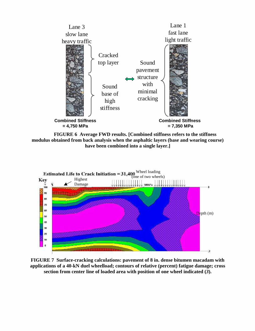
Lane 3slow lane
heavy traffic
Lane 1fast lane
light traffic
Cracked top layer
Sound base of
high stiffness
Sound pavement structure
with minimal cracking
Combined Stiffness= 4,750 MPa
Combined Stiffness= 7,350 MPa
FIGURE 6 Average FWD results. [Combined stiffness refers to the stiffnessmodulus obtained from back analysis when the asphaltic layers (base and wearing course)
have been combined into a single layer.]
FIGURE 7 Surface-cracking calculations: pavement of 8 in. dense bitumen macadam withapplications of a 40-kN duel wheelload; contours of relative (percent) fatigue damage; cross
section from center line of loaded area with position of one wheel indicated (3).
Depth (m)
Wheel loading(one of two wheels)Highest
Damage

Rowe et al. 103
7,000,000 ESALs compared to the rehabilitated structural capacity of 69,000,000 ESALs. Therehabilitated structure essentially offers an indeterminate pavement life that will need onlyperiodic resurfacing to restore the ride quality.
Mix Testing
The objective of the mixture testing was to test the materials being used in accordance with theSuperpave standards to determine what changes may be needed to NJDOT’s standard I-4 surfacecourse mix for compliance with the new standards. When this mixture was compared to theSuperpave requirements it was observed that only a very minor change to the gradation wasrequired to convert existing mixture to meet 12.5 mm Superpave requirements (4). The majorityof NJDOT’s standards for consensus properties were previously specified at the same or athigher quality values than used in the Superpave specifications.
The binder used in the surface course corresponds to a PG76-22 (see Table 3). This wouldcompare to a PG58-22, which would be used for the region as per the standard Superpaveprocedures. The PG76-22 represents 3-grade bumps (e.g. PG58-22 to PG76-22) to considerheavy and slow traffic loads.
CURRENT PERFORMANCE
The project was inspected in January 2001 and is illustrated in Figure 8. Currently, after 4 yearsof traffic, the project is performing to acceptable standards with little signs of distress.
The most recent pavement management data available for this project is presented in Figures9 and 10 that illustrate the pavement rating and skid properties.
The pavement rating data was obtained on December 11, 1998 (approximately 2 years aftersurfacing). The pavement rating is presented as both a Ride Quality Index (RQI) and SurfaceDistress Index (SDI) as measured with the ARAN profile device. (ARAN is the trade name forthe equipment manufactured by Roadware of Paris, Ontario.) The pavement ratings (RQI andSDI) are related to the condition as indicated in Table 4.
TABLE 3 Superpave Binder Test ResultsTest Parameter Results Specification Requirement
Safety/HandlingFlash Point (Cleveland Open Cup) 318°C >230°CViscosity @ 135°C 1.55 Pa-s <3 Pa-sLoss on heating 0.25% <1%
High TemperatureG*/sinδ, Original 1.56 @ 76°C >1 kPaG*/sinδ, RTFOT 3.04 @ 76°C > 2.2 kPa
Intermediate TemperatureG*/sinδ 3550 kPa @ 22°C <5000 kPa
Low TemperatureCreep Stiffness, S 220 MPa @ -12°C <300 MPam-value 0.315 @ -12°C >0.300

104 Transportation Research Circular 503: Perpetual Bituminous Pavements
Based on the above definitions the pavement rating is in a “good” to “very good” conditionwith few (if any) visible signs of deterioration.
The average skid number obtained for the site on September 6, 2000, was 49.6 and with astandard deviation of 3.3 (see Figure 10). This would meet the requirements for a traffic speed ofapproximately 70 mph and is considered acceptable.
Further long-term monitoring of the project is planned during years ahead to determine theeffectiveness of the treatments used.
The value of the engineering approach to this pavement structure has been demonstrated viathe efficiencies in the pavement structural design compared to a full reconstruction option thatwould have been used based upon a limited visual survey.
CONCLUSIONS
The study of the pavement structure at Morristown, New Jersey, illustrated the need to considerthe occurrence of surface cracking in the design and execution of pavement rehabilitationprojects in New Jersey. The specific findings obtained during this study are as follows:
• This project illustrated the need to develop pavement solutions with adequateconsideration to the mode of distress occurring on site.
• The surface cracking appears to be associated with a hard binder in the surfacingmaterials.
• FWD tests confirm that the base is of adequate stiffness for the overlay design.• The developed solution involved evaluation with a FWD and the use of polymer-
modified binders in the surface course.
FIGURE 8 Current condition.

Rowe et al. 105
TABLE 4 Ride Quality and Surface Distress CategoriesRQI/SDI Visual
CategoryRemarks
0.0 to 1.0 Very Poor Pavements that are in an extremely deteriorated condition. The facility ispassable only at reduced speeds, and with considerable ride discomfort.Large potholes and deep cracks exist. Distress occurs over 75 percent ormore of the surface.
1.0 to 2.0 Poor Pavements that have deteriorated to such an extent that they affect thespeed of free flow traffic. Flexible pavements may have large potholesand deep cracks. Distress includes raveling, cracking, and rutting thatoccurs over 50 percent or more of the surface. Rigid pavement distressincludes joint spalling, faulting, patching, cracking, and scaling, and mayinclude pumping and faulting.
2.0 to 3.0 Fair The riding qualities of pavements in this category are noticeably inferiorto those of new pavements, and may be barely tolerable for high-speedtraffic. Surface defects of flexible pavements may include rutting, mapcracking and extensive patching. Rigid pavements in this group mayhave a few joint failures, faulting and cracking, and some pumping.
3.0 to 4.0 Good Pavements in this category, although not quite as smooth as thosedescribed above, give a first class ride and exhibit few, if any, visiblesigns of surface deterioration. Flexible pavements may be beginning toshow evidence of rutting and fine random cracks. Rigid pavements maybe beginning to show evidence of slight surface deterioration as well asminor cracks and spalling.
4.0 to 5.0 Very Good Only new (or nearly new) pavements are likely to be smooth enough andsufficiently free of cracks and patches to qualify for this category. Allpavements constructed or resurfaced during the date year wouldnormally be rated very good.
• Adequate service life was achieved with only a relatively thin overlay.• This approach had significant cost benefits (savings) for the project.• Superpave mixes were not significantly different from New Jersey’s current I-4 HD
(Heavy Duty) mixes.• The pavement management information collected to date indicates that the surface is
performing adequately.
Planned monitoring of performance over the following years will further assist with thedevelopment of a rational approach to the design of pavements which exhibit severe surfacecracking.

0.0
0.5
1.0
1.5
2.0
2.5
3.0
3.5
4.0
4.5
5.0
35.00 35.50 36.00 36.50 37.00 37.50 38.00 38.50 39.00 39.50
Milepost
RQ
I or S
DI
Ride Quality Index,NorthboundSurface Distress Index,NorthboundRide Quality Index,SouthboundSurface Distress Index,Southbound
FIGURE 9 Pavement ratings (RQI and SDI) versus Milepost I-287.
0
10
20
30
40
50
60
70
34.5 35 35.5 36 36.5 37 37.5 38 38.5 39 39.5
Milepost
Skid
Num
ber
NorthboundSouthbound
FIGURE 10 Skid numbers versus Milepost I-287.

Rowe et al. 107
REFERENCES
1. Parsons Brinckerhoff. Pavement Design, Route I-287 Section 9S + 10V. Dec. 1993.2. Brown, S. F., W. S.Tam, and J. M. Brunton. Structural Evaluation and Overlay Design:
Analysis and Implementation. Proc., Sixth International Conference on the Structural Designof Asphalt Pavements, Vol. 1, Ann Arbor, Mich., 1987, pp. 1013–1028.
3. Rowe, G. M., and S. F. Brown. Fatigue Life Prediction using Visco-Elastic Analysis. Proc.,International Society of Asphalt Pavements, Seattle, Wash., 1997.
4. SWK Pavement Engineering. Evaluation of SHRP Tests and Mixture Design Procedures andVerification of Structural Improvement Following Overlay Construction on Route I-287(Sections 9S and 10V). Report Submitted to New Jersey Department of Transportation, July1998.
ADDITIONAL RESOURCE
Deacon, J. A., A. A. Tayebali, J. S. Coplantz, F. N. Finn, and C. L. Monismith. Fatigue Responseof Asphalt-Aggregate Mixes: Part III Mix Design and Analysis. SHRP Project A-003,Asphalt Research Program, Institute of Transportation Studies, University of California,Berkeley, Nov. 1992.

108
Illinois Extended-Life Hot-Mix Asphalt Pavements
ERIC HARMIllinois Department of Transportation
At the request of the hot-mix asphalt (HMA) industry, the Illinois Department of Transportation(IDOT) initiated efforts to develop contract provisions for the design and construction of“perpetual” HMA pavements. A “perpetual” pavement for this effort is defined by the AsphaltPavement Alliance as a pavement structure consisting of a rut-resistant, impermeable, and wear-resistant top structural layer, with a rut-resistant and durable intermediate layer, and a fatigue-resistant and durable base layer. IDOT believes a more appropriate term is extended-life HMApavement.
his paper describes (1) the approach taken by Illinois and its hot mix industry, and (2) the issues involved in developing the contract provisions.
PARTNERSHIP APPROACH
The approach taken was in the form of a partnership of the Illinois Department of Transportation(IDOT), academia, contractors, asphalt suppliers, and national experts. This approach ensuredthe best information, knowledge, and experiences were available to develop an appropriatespecification for Illinois conditions.
The following were represented on the task group:
• IDOT• Contractors• Asphalt suppliers• Aggregate suppliers• Academia• Industry association representatives• National experts
In the planning stages for this effort, it was agreed that a specification could be developedthrough a series of four meetings spaced 1 to 2 months apart, with various subcommitteesworking on specific issues between meetings. The first meeting was held June 14, 2000, with thegoal of having a draft document by December 31, 2000. This ambitious goal was substantiallyaccomplished.
At the first meeting, the task group determined that the main topics to be addressed could bebroken down into the following four distinct areas.
• Pavement substructure,• Material durability and stripping prevention,
T

Harm 109
• Fatigue-layer design analysis and bottom-layer mixture design, and• 20-year pavement surface.
The task group divided itself into subgroups representing these four areas. Issues, questions,and concerns discussed during the general meetings were in many instances assigned to theappropriate subgroup for consideration, with recommendations presented at the next generalmeeting.
PERPETUAL PAVEMENT DESIGN CONCEPT
The perpetual pavement concept of a three-layered system, renewable surface, middle rut-resistant layer, and lower fatigue resistant layer was explained by representatives of the AsphaltPavement Alliance. After discussing and fully understanding the concepts, the task group agreedthey were reasonable for use in Illinois.
Thickness Issues
The first challenge was to determine appropriate total thickness of the pavement structure andthicknesses for each of the three individual layers. Since 1989, IDOT has been using amechanistically based pavement-thickness design procedure. It includes limiting the maximumtensile strain at the bottom of the lower lift, as well as limiting the subgrade stress. The IDOTdesign typically results in design strain levels at or below what pavement design experts aresuggesting (i.e., 0.60 microstrain for perpetual pavement). Discussions with the design thatprocedure authors indicated that the fatigue algorithms used to characterize mixtures used inIllinois were quite conservative. As such, the existing thickness design would already have takeninto account any type of mixtures the task group would recommend. To meet the 6-month goalof having a specification, it was decided to use the current design thickness procedure with nochange. A long-term goal would be to review the thickness design to recognize a more fatigue-resistant lower layer than currently assured in the design procedure.
Prepared Subgrade
Currently, IDOT’s standard cross section for full-depth hot-mix asphalt (HMA) has thepavement built on top of 12 in. of lime modified soil with added provisions for very weaksubgrade soils. The department proposed to replace the 12 in. of lime-modified soil with 12 in. ofaggregate subbase. This subbase is used typically in the Chicago area when reconstructingpavements. The gradation is such that a wide range of sized material can be used, but does resultin a drainable layer. A review of the reduction in strain at the bottom of the HMA pavementproduced a microstrain reduction of 2. Questions were raised as to the benefit of a 2-microstrainreduction compared to the cost of incorporating 12 in. of granular subbase, especially in areas ofthe state where such aggregate is not readily available. Estimated cost increases ranged from 6 to14 percent of a typical cross-section cost, depending on the specific project. This issue could notbe resolved by the group and was forwarded to IDOT management to resolve.

110 Transportation Research Circular 503: Perpetual Bituminous Pavements
Underdrains
Current IDOT design standards require longitudinal underdrains to be placed under theshoulder/pavement joint on both sides of the pavement. The pipe is located low enough to drainthe aggregate layer it if exists, or 24 in. below the surface of the pavement when the pavement isbuilt on top of lime-modified soil. The question was raised as to the value of underdrain in thecross section use, especially with clay-type soils in Illinois. After some discussion, it wasdecided that not enough performance data existed to eliminate the underdrain at this time.
Fatigue-Resistant Layer
Although the pavement thickness design procedure was felt to be conservative in regards tofatigue using existing IDOT mixtures, it was decided to develop a “rich bottom base” to improvethe fatigue resistance. Various different mixes were discussed in terms of appropriateness inmeeting the characteristics of a highly fatigue-resistant HMA. From a mix design perspective, avery specialized mixture could be designed, but its practicality and resulting cost was questioned.To reduce confusion with additional mix designs, differing aggregate requirements, and varyingproduction criteria during construction, it was deemed most appropriate to modify the mixtureused in the middle layer
The selected rich-bottom base used the middle-layer mix design with an asphalt content thatprovided 2.5 percent air voids at the same gyration level. Adding one-half percent more ofasphalt to the 4 percent design wa suggested, but the task group agreed that designing for 2.5percent voids was more realistic in defining the mixture characteristics desired in the layer. Theadditional asphalt should also improve moisture damage resistance, provide additional fatiguelife, and be easy to place and compact. Also, a higher in-place density requirement of less then6.0 percent voids for this layer was included. All these characteristics would ensure a durablefatigue-resistant layer. This layer would be constructed in one 4-in. lift.
Intermediate Pavement Layer
After reviewing performance data and the members’ review of the mix design requirements, thetask group determined that the department’s current specified binder mixture and mix designprocedure was appropriate for the intermediate pavement layer. The design procedure andingredient requirements follow the intent of Superpave, and historically Illinois has provided rut-resistant mixtures. The appropriate gyration level would be utilized for the expected traffic overa 20-year period, as recommended by Superpave.
Renewable Surface Layer
To achieve the goal of a 20-year surface life, the use of stone matrix asphalt (SMA) was chosento resist both rutting and durability problems for the renewable surface layer. The use of IDOT’sdense-graded mixtures was discussed, but ultimately not pursued. The task group felt SMA couldprovide a higher level of long-term durability due to its mixture characteristics.
To determine appropriate thickness of the surface layer, a shear stress analysis of thepavement structures was conducted and the results of rutting and surface cracking studies werereviewed. In most cases, the studies indicate that rutting and cracking occur in the top 4 in. Basedon the analysis and studies, the following top layer thicknesses were selected for the SMA:

Harm 111
Traffic Total SMA Thickness (Inches)Low 2
Medium 4High 6
For the very high equivalent single-axle load (ESAL) pavements, a 6-in. total thickness ofSMA was felt to give a factor of safety to help resist rutting. (Although the specific definitions oflow, medium, and high have not been finalized, high may ultimately be defined as 25 millionESALs or greater, based on a 20-year traffic analysis.) For the lower-volume pavements, no needwas recognized for the high rut-resistant SMA in the lower part of the surface layer.
However, the task group agreed that the top 6 in. of the pavement would require modifiedbinder to minimize surface cracking. For those pavements with either 2 or 4 in. of SMA, theremaining 4 or 2 in., respectively, would be of the intermediate layer mixture with modifiedasphalt.
Asphalt Penetration Grade Selection
The use of polymer-modified asphalt cement in both the base layer and intermediate layer wasnot felt to be cost-effective. It was decided to use modified asphalt in the 6 in. of the surfacelayer to help resist surface cracking and rutting. The department’s current penetration gradeselective requirement for full-depth pavements for northern Illinois was felt appropriate forstatewide use. It is recognized this is a conservative approach for pavements built in the southernparts of the state. However, the approach would help minimize low-temperature cracking and thepolymer would improve durability. For the 6-in. surface layer, “grade bumping” to accommodateslow and standing traffic will use the department’s current guidelines.
Use of Hydrated Lime
Illinois uses liquid additives when it determines a mixture is susceptible to moisture damage(stripping). Based on the Illinois version of AASHTO T-283, there were suggestions to make theexisting test procedure more stringent. Ultimately, the task group elected to require the use ofhydrated lime for all mixtures used in the extended-life pavement. Along with the mandatory useof lime, the mixtures will still have to pass the department’s current tensile strength–ratiorequirements. Any future changes to the test procedures would be considered for all mixtures,not just for perpetual pavements.
Mixture Durability Enhancements
The task group agreed on the following items to enhance the durability of the mixtures and soincrease the life of the pavement structure.
• Increase minimum lift thickness to 3 to 6 times nominal maximum aggregate size toallow higher in-place density.
• Require positive dust control on HMA plants for better mixture production control.• Require priming with a polymer material between each lift to promote bonding.

112 Transportation Research Circular 503: Perpetual Bituminous Pavements
• Require all-virgin aggregate in the bottom layer. This eliminates variability of mixturestiffness due to reclaimed asphalt pavement.
• Require the use of a material-transfer vehicle or a paving machine capable of re-mixingthe bituminous mixture for all lifts of all mixtures to reduce the potential for segregation. Toeliminate premature pavement fatigue from the vehicle, its use is permitted only on constructedlifts 10 in. or greater in thickness.
• Revise in-place field density testing to promote uniform levels of density across the mat.• Increase the in-place density requirements for the middle layer to less than 7 percent air
voids.
Longitudinal Joint Construction Practices
The task group reviewed the need to improve longitudinal joint durability. It was felt thelongitudinal joints would be the portion of the pavement prone to long-term durability problems.The task group discussed procedures such as full-width paving to eliminate longitudinal joints,and cutting of the joint prior to the adjacent lane being paved to improve the density at the joint.
Three recommendations were ultimately made to improve durability of longitudinal joints.First, improve the quality of the material near the joint by requiring mainframe screed extensionsand utilizing good paving practices. Second, change the field density–testing procedures to putmore emphasis on nuclear tests 2 ft from the joints. Third, require the use of a spray-on polymer-modified tack coat on the vertical face of all lifts that will become longitudinal joints. This tackcoat will extend on existing lifts for a width of 6 in. to the side of the existing joint. Incombination, all three procedures should improve the life of the longitudinal joints.
Individual Layer Thickness Tolerance
Due to the importance of each of the three layers—the bottom fatigue layer, the intermediatelayer, and the surface layer—the concern for construction thickness tolerances of each layer wasdiscussed. The pavement thickness design is already conservative, with the lower fatigue layergiven the same fatigue resistant as the intermediate layer, and with modified asphalt binder beingrequired in the upper 6 in., which fully encompasses the shear zone of 3 to 5 in. Therefore it wasdecided that existing department construction tolerances and total pavement thicknessrequirements would be used.
Pavement Smoothness Requirements
The department has an ongoing pavement smoothness initiative to improve the smoothness ofnewly constructed pavements. The department believes that smoother constructed pavementsaddress the public’s desire for smoother pavements. Also, pavements built smooth will remainsmoother throughout their service life. The task group concurred with including the department’smost stringent pavement smoothness specifications for the extended-life HMA pavements.

Harm 113
CONCLUSION
The task group substantially met the goal of having draft documents ready by December 31,2000. This was accomplished by taking current IDOT pavement and mixture designs, as well asconstruction practices, and reviewing them for appropriateness when using the three-layeredperpetual pavement concept, and then making adjustments where needed. Most of the effort wasin improving the durability of mixtures to ensure that they last indefinitely for the bottom andintermediate layers and at least 20 years for the renewable surface layer, with no rutting, surfacecracking, or durability issues.
One major item yet unresolved is the need for a 12-in. granular subgrade under the three-layered HMA pavement. An approach being considered is to require the aggregate subbase onlyfor very high levels of traffic.
Two other goals currently being addressed by IDOT and the HMA industry are to developspecifications for SMA mixtures for medium- and low-traffic situations to ensure durability, andspecifications for incorporating hydrated lime in HMA mixtures.
Future efforts will include reviewing the thickness-design procedure to account for thedifferent mixtures used in the three layers, as well as maximizing the benefits of such a design.
Currently, the HMA industry in Illinois is pursuing projects where the extended-life HMApavements specifications can be included.

114
APPENDIX
Perpetual Bituminous Pavements Authors
Mark BuncherDirector of Field ServicesAsphalt InstituteP.O. Box 14052Lexington, KY 40512859-288-4972Fax: [email protected]
Jean-François CortéTechnical DirectorLaboratoire Central des Ponts et ChausséesRoute de Bouaye44340 BouguenaisFrance+33-2408-45815Fax: [email protected]
Frank FeeAsphalt Pavement TechnologistCitgo Asphalt Refining Company401 Woodward RoadMoylan, PA19063610-565-6863Fax: [email protected]
Brian W. FerneTransport Research LaboratoryInfrastructure DivisionOld Wokingham RoadCrowthorne, Bershire RG45 6AUUnited Kingdoom+44-1344-770668Fax: [email protected]
Eric HarmEngineer of Materials—Physical ResearchIllinois Department of Transportation126 East Ash StreetSpringfield, Illinois 62704-4766217-782-7202Fax: [email protected]
John T. HarveyPavement Research Center1353 South 46th Street, Building 480University of California–BerkeleyBerkeley, California 94804510-231-9513Fax: [email protected]
Kevin HerrittSupervising Transportation EngineerCalifornia Department of Transportation1120 N Street, Room 2208P.O. Box 942874 MS-28Sacramento, CA 94272-0001916-653-3170Fax: [email protected]
Ira J. HuddlestonExecutive DirectorAsphalt Pavement Association of Oregon5240 Gaffin Road SESalem, OR 97301503-363-3858Fax: [email protected]

Perpetual Bituminous Pavements Authors 115
Eul-Bum LeeAssistant Research EngineerPavement Research CenterUniversity of California–Berkeley1353 S. 46th Street, Building 452-TRichmond, CA 94808510-231-5694Fax: [email protected]
Fenella M. LongPavement Research CenterUniversity of California–Berkeley1353 S. 46th Street, Building 452-TRichmond, CA 94808510-231-5694Fax: [email protected]
Joe P. MahoneyProfessor of Civil and
Environmental EngineeringUniversity of Washington201 Moore Hall Box 352700Seattle, Wash. 98195-2700206-586-1760Fax: [email protected]
Carl L. MonismithR. Horonjeff Professor of Civil EngineeringUniversity of California–BerkeleyDepartment of Civil EngineeringRoom 115, McLaughlin HallBerkeley, CA 94720510-231-9587Fax: [email protected]
Leslie Ann MyersPavement Research SpecialistERES Consultants9030 Red Branch Road, Suite 210Columbia, MD 21045410-997-6181Fax: 410-997-6413
David E. NewcombVice President, Research and TechnologyNational Asphalt Pavement Association5100 Forbes BoulevardLanham, MD 20706-4413301-731-4748Fax: [email protected]
Michael NunnTransport Research LaboratoryInfrastructure DivisionOld Wokingham RoadCrowthorne, Bershire RG45 6AUUnited Kingdom+44-1344-770210Fax: [email protected]
Reynaldo RoqueDepartment of Civil EngineeringUniversity of Florida345 Weil HallP.O. Box 116580Gainesville, Fla. 32611-6580352-392-7368Fax: [email protected]
Geoffrey RoweAbatech, Inc.73 Old Dublin Pike, #312Doylestown, PA 18901215-258-3640Fax: 561-679-2464Mobile: [email protected]
Robert SauberProject EngineerGeotechnical Engineering UnitNew Jersey Department of TransportationP.O. Box 600Trenton, NJ 08625-0600609-530-3861Fax: 609-530-5540Mobile: 609-540-1180
116 Transportation Research Circular 503: Perpetual Bituminous Pavements
Nassef SolimanAssistant Vice PresidentParsons-Brinckerhoff–FG, Inc.506 Carnegie Center DrivePrinceton, NJ 08540609-734-7051Fax: 609-734-6900
Jim St. MartinExecutive DirectorAsphalt Pavement Association, California23161 Mill Creek Drive, Suite 315Laguna Hills, CA 92653800-734-9996Fax [email protected]
Harold L. Von QuintusSenior Research FellowFugro-Brent Rauhut Engineering, Inc.8240 Mopac, Suite 220Austin, TX 78759-8869512-346-0870Fax: [email protected]