transmitter in field housing pr5230 - minebea … · instrument manual. transmitter in field...
TRANSCRIPT

Instrument Manual
Transmitter in Field Housing PR5230
9499 050 52301 Instrument Manual Edition 4 09.09.2010 for PR5230 Release: 1.00
Sartorius Mechatronics T&H GmbH, Meiendorfer Str. 205, 22145 Hamburg, Germany Tel:+49.40.67960.303 Fax:+49.40.67960.383
Please note Any information in this document is subject to change without notice and does not represent a commitment on the part of Sartorius unless legally prescribed. This product should be operated only by trained and qualified personnel. In correspondence concerning this product the type, name and release number as well as all license numbers in relation to the product have to be quoted.
Bitte beachten Alle Angaben in diesem Dokument sind - soweit nicht gesetzlich vorgegeben - unverbindlich für Sartorius und stehen unter Änderungsvorbehalt. Die Bedienung des Produktes darf nur von geschultem, fach- und sachkundigem Personal durchgeführt werden. Bei Schriftwechsel über dieses Produkt bitte Typ, Bezeichnung und Versionsnummer sowie alle mit dem Produkt in Zusammenhang stehenden Lizenznummern angeben.
PR5230 Instrument Manual List of Contents
Sartorius EN-3
List of Contents
1 Safety Information ............................................................................................................................................................................... 9 1.1 Electrical Protective Class.......................................................................................................................................................................... 9 1.2 Intended Use..................................................................................................................................................................................................9 1.3 Initial Inspection........................................................................................................................................................................................... 9 1.4 Before Commissioning................................................................................................................................................................................9
1.4.1 Installation ........................................................................................................................................................................................ 9 1.4.2 Opening the Instrument .............................................................................................................................................................10 1.4.3 Connection of a protective earth conductor to PR5230 .................................................................................................10 1.4.4 Power Connection PR5230 ........................................................................................................................................................10 1.4.5 Failure and Excessive Stress .......................................................................................................................................................11 1.4.6 Important Note..............................................................................................................................................................................11 1.4.7 Maintenance and Repair.............................................................................................................................................................11
2 Transmitter in Field Housing ...........................................................................................................................................................12 2.1 Overview of the Instrument ...................................................................................................................................................................12
2.1.1 Communication Protocols..........................................................................................................................................................12 2.2 Housing .........................................................................................................................................................................................................13
2.2.1 Housing Dimensions.....................................................................................................................................................................13 2.3 Display and Controls .................................................................................................................................................................................14
2.3.1 Display ..............................................................................................................................................................................................14 2.3.2 Status LEDs......................................................................................................................................................................................16 2.3.3 Buttons .............................................................................................................................................................................................17 2.3.4 Operating via VNC ........................................................................................................................................................................17 2.3.5 Operation Using Softkeys...........................................................................................................................................................20 2.3.6 Selection Using the Navigation Keys (VNC)..........................................................................................................................20 2.3.7 Tool Tip (VNC) .................................................................................................................................................................................21
2.4 Overview of Connections.........................................................................................................................................................................22 2.4.1 Plug-in Cards/Junction Board...................................................................................................................................................23
3 Options...................................................................................................................................................................................................24 3.1 Option Y2......................................................................................................................................................................................................25
3.1.1 Safety Instructions........................................................................................................................................................................25 3.1.2 Description ......................................................................................................................................................................................25 3.1.3 Marking ............................................................................................................................................................................................25 3.1.4 Outputs.............................................................................................................................................................................................25 3.1.5 In Connection with Option W1 ................................................................................................................................................25 3.1.6 In Connection with Option WE1 ..............................................................................................................................................25 3.1.7 Installation ......................................................................................................................................................................................26 3.1.8 Repairs/Cleaning/Maintenance.................................................................................................................................................26 3.1.9 Environmental Conditions..........................................................................................................................................................26

List of Contents PR5230 Instrument Manual
EN-4 Sartorius
3.2 Option WE1 ................................................................................................................................................................................................. 27 3.2.1 Safety Instructions....................................................................................................................................................................... 27 3.2.2 Description ..................................................................................................................................................................................... 27 3.2.3 Marking ........................................................................................................................................................................................... 27 3.2.4 Display.............................................................................................................................................................................................. 27 3.2.5 In Connection with Option Y2 ................................................................................................................................................. 27 3.2.6 Weighing Electronic Board for Zone 1 and 21................................................................................................................... 28 3.2.7 Connection within the Ex Area................................................................................................................................................ 29 3.2.8 Installation ..................................................................................................................................................................................... 30 3.2.9 Repairs/Cleaning/Maintenance................................................................................................................................................ 34 3.2.10 Technical Data............................................................................................................................................................................... 35
4 Installing the Instrument and Plug-in Cards.............................................................................................................................. 37 4.1 Mechanical Preparation .......................................................................................................................................................................... 37 4.2 Hardware Construction ........................................................................................................................................................................... 37
4.2.1 Main Board..................................................................................................................................................................................... 38 4.2.2 Display Board................................................................................................................................................................................. 39 4.2.3 Weighing Electronic Board ....................................................................................................................................................... 39 4.2.4 Cable Gland and Connection.................................................................................................................................................... 40 4.2.5 Network Port ................................................................................................................................................................................. 42 4.2.6 Optocoupler Inputs...................................................................................................................................................................... 42 4.2.7 Opto-decoupled Outputs (optional)....................................................................................................................................... 44 4.2.8 Relay Outputs ................................................................................................................................................................................ 45 4.2.9 Interface RS-485 .......................................................................................................................................................................... 46 4.2.10 Interface RS-232 .......................................................................................................................................................................... 54
4.3 Accessories................................................................................................................................................................................................... 56 4.3.1 Installing Plug-in Cards.............................................................................................................................................................. 56 4.3.2 PR5230/06 Analog Output Board ........................................................................................................................................... 57 4.3.3 PR5230/22 Load Cell Junction Board .................................................................................................................................... 58 4.3.4 PR1721/41 ProfiBus-DP Interface .......................................................................................................................................... 59 4.3.5 PR1721/42 InterBus-S Interface ............................................................................................................................................. 61 4.3.6 PR1721/44 DeviceNet Interface .............................................................................................................................................. 63 4.3.7 PR1721/45 CC-Link Interface................................................................................................................................................... 66 4.3.8 PR1721/46 ProfiNet I/O Interface........................................................................................................................................... 68 4.3.9 PR1721/47 EtherNet-IP Interface........................................................................................................................................... 70 4.3.10 PR5230/30 Ethernet Socket...................................................................................................................................................... 72 4.3.11 PR5230/31 Ethernet Cable........................................................................................................................................................ 72
4.4 Connecting Load Cells ............................................................................................................................................................................. 73 4.4.1 Connecting a Load Cell with 4-Wire Cable.......................................................................................................................... 73 4.4.2 Connecting PR6221 Load Cells ................................................................................................................................................ 73 4.4.3 Connecting up 2 to 4 Load Cells via PR5230/22 Load Cell Junction Board.............................................................. 74 4.4.4 Connecting up 2 to 8 Load Cells using 6-Wire Connecting Cable............................................................................... 78 4.4.5 Connecting Load Cells with External Supply....................................................................................................................... 79 4.4.6 Connecting Platforms (CAP...) .................................................................................................................................................. 80
PR5230 Instrument Manual List of Contents
Sartorius EN-5
5 Commissioning ....................................................................................................................................................................................81 5.1 Data Protection/Power Failure...............................................................................................................................................................81
5.1.1 CAL Switch ......................................................................................................................................................................................81 5.2 Switching on the Instrument .................................................................................................................................................................82
5.2.1 Resetting the Instrument/Activating Network ‚DHCP’......................................................................................................82 5.2.2 Searching the Instrument in the Network with 'Indicator Browser'............................................................................85
5.3 Operation Using a PC................................................................................................................................................................................88 5.3.1 Operation Using the VNC Program .........................................................................................................................................88 5.3.2 System Messages during Input (VNC).....................................................................................................................................89 5.3.3 Operation Using Web Browser..................................................................................................................................................90 5.3.4 Function INFO ................................................................................................................................................................................92 5.3.5 Setup Function (VNC) ..................................................................................................................................................................92 5.3.6 Setup Menu (VNC) ........................................................................................................................................................................93 5.3.7 Calibration Menu ..........................................................................................................................................................................94
5.4 Calibration....................................................................................................................................................................................................95 5.4.1 Displaying Calibration Data .......................................................................................................................................................95 5.4.2 Selecting the Calibration Mode................................................................................................................................................96 5.4.3 Determining the Maximum Capacity [Max].........................................................................................................................97 5.4.4 Determining the Scale Interval.................................................................................................................................................99 5.4.5 Determining the Dead Load.................................................................................................................................................... 100 5.4.6 Calibration with Weight [by load]........................................................................................................................................ 102 5.4.7 Calibration with mV/V Value [by mV/V].............................................................................................................................. 103 5.4.8 Calibration with Load Cell Data (smart calibration) ....................................................................................................... 104 5.4.9 Subsequent Dead Load Correction ....................................................................................................................................... 105 5.4.10 Determination Test Value/Display Test Value.................................................................................................................... 105 5.4.11 Finishing/Saving the Calibration........................................................................................................................................... 106 5.4.12 Parameter Input ......................................................................................................................................................................... 107
5.5 Error Messages ......................................................................................................................................................................................... 110 5.5.1 Measuring Circuit Error Messages ........................................................................................................................................ 110 5.5.2 General Error Messages............................................................................................................................................................ 110 5.5.3 Error Messages with Ex Applications ................................................................................................................................... 111
5.6 Configuring General Parameters........................................................................................................................................................ 112 5.6.1 Serial Interfaces [Serial ports]................................................................................................................................................ 112 5.6.2 Date and Time ............................................................................................................................................................................. 115 5.6.3 Operating parameters............................................................................................................................................................... 116 5.6.4 Printing parameter .................................................................................................................................................................... 117 5.6.5 Fieldbus parameter .................................................................................................................................................................... 118 5.6.6 Network parameter ................................................................................................................................................................... 120 5.6.7 Display items................................................................................................................................................................................ 121
5.7 Limit Values, Digital Inputs and Outputs......................................................................................................................................... 122 5.7.1 Conditions for Limit Values and Digital Inputs, States for Outputs .......................................................................... 122 5.7.2 Configuring Digital Inputs and Outputs............................................................................................................................. 123 5.7.3 Configuring Limit Values ......................................................................................................................................................... 126 5.7.4 Display of Limits and Digital Inputs/Outputs.................................................................................................................... 128
List of Contents PR5230 Instrument Manual
EN-6 Sartorius
5.8 Analog Output..........................................................................................................................................................................................129 5.8.1 Adapting the Analog Output..................................................................................................................................................130
5.9 Retrieve eventlog memory ...................................................................................................................................................................131 5.9.1 FatalError ......................................................................................................................................................................................131 5.9.2 Setup ..............................................................................................................................................................................................132 5.9.3 Indicator........................................................................................................................................................................................132 5.9.4 Powerfail .......................................................................................................................................................................................132
5.10 Backup of EAROM...................................................................................................................................................................................132 5.11 ConfigureIt Professional .......................................................................................................................................................................133
5.11.1 Installation ...................................................................................................................................................................................133 5.11.2 Program Start..............................................................................................................................................................................135 5.11.3 Establish Communication to the Instrument ....................................................................................................................137 5.11.4 Transfer Dataset from Instrument to PC ............................................................................................................................138 5.11.5 Store Current Dataset on PC ..................................................................................................................................................139 5.11.6 Store Current Dataset or Selected Parameters in the Instrument .............................................................................141 5.11.7 Reset the Instrument to Factory Default............................................................................................................................142 5.11.8 Exporting a Dataset as Printable File...................................................................................................................................142 5.11.9 Operation of the Instrument via Browser (VNC)..............................................................................................................143 5.11.10 Closing the Program..................................................................................................................................................................143
6 J-Bus/ModBus Protocol ..................................................................................................................................................................144 6.1 General Description ................................................................................................................................................................................144 6.2 ModBus-RTU.............................................................................................................................................................................................145 6.3 ModBus-TCP/-UDP..................................................................................................................................................................................146 6.4 Functions....................................................................................................................................................................................................147
6.4.1 Function 1 or 2: Reading n Bits.............................................................................................................................................147 6.4.2 Function 3 or 4: Reading n Successive Words ..................................................................................................................147 6.4.3 Function 5: Writing a Bit .........................................................................................................................................................148 6.4.4 Function 6: Writing a Word....................................................................................................................................................148 6.4.5 Function 8: Diagnosis................................................................................................................................................................149 6.4.6 Function 15: Writing n Successive Bits...............................................................................................................................149 6.4.7 Function 16: Writing n Successive Words..........................................................................................................................150
6.5 Error Messages .........................................................................................................................................................................................150 6.6 Word Addresses........................................................................................................................................................................................151
7 SMA Protocol .....................................................................................................................................................................................152 7.1 General .......................................................................................................................................................................................................152 7.2 Description of Used Symbols...............................................................................................................................................................152 7.3 SMA Command Set.................................................................................................................................................................................153
7.3.1 Requesting a Weight.................................................................................................................................................................153 7.3.2 Controlling the Scale ................................................................................................................................................................155 7.3.3 Scale Diagnosis............................................................................................................................................................................155 7.3.4 Scale Data.....................................................................................................................................................................................156 7.3.5 Scale Information.......................................................................................................................................................................156 7.3.6 Escape Command .......................................................................................................................................................................156
PR5230 Instrument Manual List of Contents
Sartorius EN-7
7.4 SMA Reply Messages.............................................................................................................................................................................. 156 7.4.1 Standard Reply............................................................................................................................................................................ 156 7.4.2 Reply with Unknown Command ........................................................................................................................................... 158 7.4.3 Reply in Case of Communication Error............................................................................................................................... 158 7.4.4 Reply with Diagnosis Command............................................................................................................................................ 158 7.4.5 Reply with ‘A’ and ‘B’ Command........................................................................................................................................... 159 7.4.6 Scale Reply with ‘I’ and ‘N’ Commands............................................................................................................................... 160
7.5 Communication Error ............................................................................................................................................................................ 161
8 Asycom Protocol .............................................................................................................................................................................. 162 8.1 Commands of the Weight Function.................................................................................................................................................. 162 8.2 Other Commands .................................................................................................................................................................................... 163 8.3 SPM Commands....................................................................................................................................................................................... 163 8.4 Error Messages for Asycom Commands........................................................................................................................................... 164
9 Fieldbus Interface ............................................................................................................................................................................ 165 9.1 Fieldbus Interface Protocol.................................................................................................................................................................. 165
9.1.1 Write Window (Input Area) .................................................................................................................................................... 166 9.1.2 Read Window (Output Area) .................................................................................................................................................. 166 9.1.3 Reading and Writing Data....................................................................................................................................................... 166
9.2 Description of the I/O Area (Read / Write Window) .................................................................................................................... 167 9.2.1 Input Area..................................................................................................................................................................................... 167 9.2.2 Output Area ................................................................................................................................................................................. 168 9.2.3 Reading and Writing Register via Fieldbus........................................................................................................................ 169 9.2.4 Example: Reading the Gross Weight.................................................................................................................................... 171
9.3 Fieldbus Register ..................................................................................................................................................................................... 172 9.3.1 Register 0: IO Status Bits for Reading................................................................................................................................. 172 9.3.2 Register 1: Scale Status............................................................................................................................................................ 172 9.3.3 Register 2: State of State-Controlled Action Bits ........................................................................................................... 173 9.3.4 Register 4: Calibration Information, Error Byte ............................................................................................................... 173 9.3.5 Register 5: Device Type and Software Release ................................................................................................................. 174 9.3.6 Register 6: Board Number....................................................................................................................................................... 174 9.3.7 Register 7: (Reserved) ............................................................................................................................................................... 174 9.3.8 Register 8 ...15: Weight Data.................................................................................................................................................. 174 9.3.9 Register 24 ... 29: Limit Values (Read/Write) ..................................................................................................................... 175 9.3.10 Register 30, 31: Fixed Values (Read/Write) ........................................................................................................................ 175 9.3.11 Register 80 ... 89: State-Controlled Action Bits (Write) ................................................................................................ 175
10 Global SPM Variables...................................................................................................................................................................... 176
11 Configuration print-out ................................................................................................................................................................ 178
12 Repairs and Maintenance.............................................................................................................................................................. 180 12.1 Battery for Date/Time ............................................................................................................................................................................ 180
12.1.1 Battery Replacement................................................................................................................................................................. 180 12.2 Solder Work .............................................................................................................................................................................................. 181 12.3 Cleaning ..................................................................................................................................................................................................... 181
13 Disposal............................................................................................................................................................................................... 181
List of Contents PR5230 Instrument Manual
EN-8 Sartorius
14 Specifications.....................................................................................................................................................................................182 14.1 Instructions for Use of 'Free Software' ............................................................................................................................................182 14.2 Decoding of the Serial Number..........................................................................................................................................................182 14.3 General Data .............................................................................................................................................................................................182
14.3.1 Backup Battery for Time/Date................................................................................................................................................182 14.3.2 Power Connection 230 V AC ..................................................................................................................................................182 14.3.3 Power Connection 24 V DC.....................................................................................................................................................182
14.4 Effect of Ambient Conditions .............................................................................................................................................................183 14.4.1 Environmental Conditions.......................................................................................................................................................183 14.4.2 Electromagnetic Compatibility (EMC) .................................................................................................................................183 14.4.3 RF Interference Suppression...................................................................................................................................................183
14.5 Weighing Electronics .............................................................................................................................................................................184 14.5.1 Load Cells ......................................................................................................................................................................................184 14.5.2 Connecting Cable .......................................................................................................................................................................184 14.5.3 Principle ........................................................................................................................................................................................184 14.5.4 Accuracy and Stability..............................................................................................................................................................184 14.5.5 Sensitivity .....................................................................................................................................................................................184 14.5.6 Analog Output (Option PR5230/06) ....................................................................................................................................185 14.5.7 Digital Inputs ...............................................................................................................................................................................185 14.5.8 Digital Outputs............................................................................................................................................................................185 14.5.9 Serial Interfaces ..........................................................................................................................................................................185 14.5.10 Network Interface......................................................................................................................................................................186 14.5.11 Fieldbus Interfaces (Options)..................................................................................................................................................186
14.6 Mechanical Data......................................................................................................................................................................................186 14.6.1 Construction ................................................................................................................................................................................186 14.6.2 Dimensions/Weights..................................................................................................................................................................186
14.7 Use in Legal-for-Trade Mode ..............................................................................................................................................................186 14.7.1 Documentation for Verification on the Enclosed CD.....................................................................................................186 14.7.2 Additional Instructions.............................................................................................................................................................186
15 Index.....................................................................................................................................................................................................187
16 Appendix .............................................................................................................................................................................................191
PR5230 Instrument Manual Safety Information
Sartorius EN-9
1 Safety Information
1.1 Electrical Protective Class
This instrument has been built and tested in compliance with the safety regulations for measuring and control instrumentation for protective class I (protective earth connection) according to IEC 1010/EN61010 or VDE 0411. The instrument was in perfect condition with regard to safety features when it left the factory. To maintain this condition and to ensure safe operation, the operator must follow the instructions and observe the warnings in this manual.
1.2 Intended Use The instrument is intended for use as an indicator for weighing functions. Product operation, commissioning and maintenance must be performed by trained and qualified personnel who are aware of and able to deal with the related hazards and take suitable measures for self-protection. The instrument reflects the state of the art. The manufacturer does not accept any liability for damage caused by other system components or due to incorrect use of the product.
1.3 Initial Inspection Check the content of the consignment for completeness and inspect it visually for signs of damage that may have occurred during transport. If there are grounds for rejection of the goods, a claim must be filed with the carrier immediately and the Sartorius sales or service organization must be notified.
1.4 Before Commissioning
Visual inspection!
Before commissioning and after and storage or transport, inspect the instrument visually for signs of mechanical damage.
1.4.1 Installation
The instrument housing meets IP 66. Mount the instrument with the cable entry glands pointing downwards. To ensure proper cooling of the instrument, make sure air circulation around the instrument is not blocked. Avoid exposing the instrument to excessive heat; e.g., from direct sunlight. Ambient conditions must be taken into account at all times. With outdoor mounting, make sure that adequate weather protection is provided (for temperatures, see Chapter 14.4.1).
Safety Information PR5230 Instrument Manual
EN-10 Sartorius
1.4.2 Opening the Instrument
Danger! High Voltage!
Working on the instrument while it is switched on may have life-threatening consequences. Disconnect the instrument from the supply voltage. Any time covers or parts are removed; live parts or terminals may be exposed. Capacitors in the unit may still be charged also after disconnecting the unit from all voltage sources.
This instrument contains electrostatically sensitive components. For this reason, an equipotential bonding conductor must be connected when working on the open instrument (antistatic protection).
1.4.3 Connection of a protective earth conductor to PR5230
1.4.3.1 Version 230 V AC
The instrument must be connected to protective earth via a protective earth conductor (PE) in the power connector. The power cable contains a protective earth conductor which must not be interrupted inside or outside the instrument. The PE conductor is connected to the housing inside the instrument.
1.4.3.2 Version 24 V DC
The instrument must be connected to the protective earth conductor. The connection can be established via the housing side wall.
1.4.4 Power Connection PR5230
The instrument does not have a power switch and is ready for operation immediately after connecting the supply voltage.
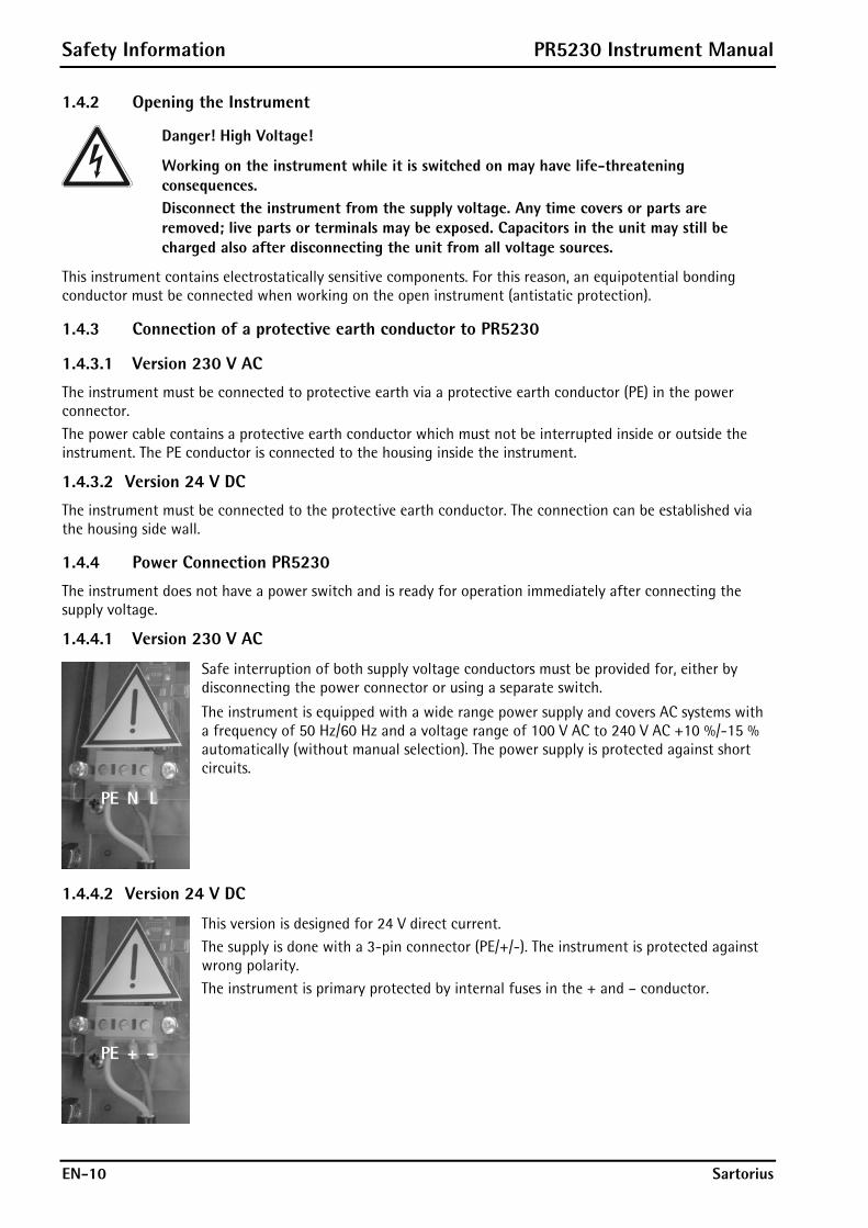
1.4.4.1 Version 230 V AC
Safe interruption of both supply voltage conductors must be provided for, either by disconnecting the power connector or using a separate switch.
The instrument is equipped with a wide range power supply and covers AC systems with a frequency of 50 Hz/60 Hz and a voltage range of 100 V AC to 240 V AC +10 %/-15 % automatically (without manual selection). The power supply is protected against short circuits.
1.4.4.2 Version 24 V DC
This version is designed for 24 V direct current. The supply is done with a 3-pin connector (PE/+/-). The instrument is protected against wrong polarity. The instrument is primary protected by internal fuses in the + and – conductor.
PR5230 Instrument Manual Safety Information
Sartorius EN-11
1.4.5 Failure and Excessive Stress
If there is any reason to assume that safe operation of the instrument is no longer ensured, shut it down and make sure it cannot be used. Safe operation is no longer ensured if any of the following is true: - The instrument is physically damaged. - The instrument does not function. - The instrument has been subjected to stresses beyond the tolerance limits (e.g., during storage or
transport).
1.4.6 Important Note
Make sure that the construction of the instrument is not altered to the detriment of safety. In particular, leakage paths, air gaps (of live parts) and insulating layers must not be reduced. Sartorius cannot be held responsible for personal injury or property damage caused by an instrument repaired incorrectly by a user or installer.
1.4.7 Maintenance and Repair
Maintenance work must be carried out only by a trained technician aware of the involved hazards, whereby the relevant precautions must be taken in account.
1.4.7.1 Static Sensitive Components
This instrument contains electro-statically sensitive components. Therefore, potential equalization must be provided when working at the instrument (antistatic protection).
1.4.7.2 Replacing of Fuses in PR5230 with Option Y2/WE1
Caution! In PR5230 with option Y2/WE1 the replacing of fuses are not allowed!
1.4.7.3 Replacing of Fuses in PR5230 without Option Y2/WE1
Only the fuses specified in Chapter 14.3 are permissible!

Transmitter in Field Housing PR5230 Instrument Manual
EN-12 Sartorius
2 Transmitter in Field Housing The instrument is equipped with a 128 x 64 pixel display for weight values with max. 6 digits and additional status indication.
2.1 Overview of the Instrument - Accuracy 10,000 e (Class III) for the weighing electronics - High-speed conversion with response times from 10 msec - Weight indication with status by monochrome 128 x 64 pixel display - 3 function keys in the housing, function configurable - Wall-mounted stainless steel housing, with IP 66 protection - LAN adaptor with 10/100 Mbit/sec for data transfer, calibration, parameterization - RS-232 interface, built-in; for connecting e.g. a printer or a remote indicator - RS-485 interface, built-in; for connecting e.g. PC - Expansion possible by addition of following plug-in circuit boards (3 slots):
- Analog output board PR5230/06 - Load cell junction board PR5230/22 - Interfaces PR1721/4x
- 3 opto-decoupled outputs (optional) - 3 configurable relay outputs with change-over contact - 3 configurable optocoupler inputs, potential-free internal supply possible (optional) - Galvanically isolated interfaces (except RS-232) - Wide range power supply for 100 to 240 V AC, protection class I (protective earth) - Version PR5230 for 24 V direct current - Version PR5230 with intrinsically safe load cell supply (optional) - Plug-in connections inside the instrument for load cells, inputs/outputs, LAN adaptor, serial interfaces - Calibration using PC tool (Browser/VNC) or ConfigureIt - Calibration using weights, by entering mV/V values, or directly, using load cell data ("smart calibration") - Software configuration of the interface cards, e.g. for remote display or printer - Analog test for the weighing electronics
2.1.1 Communication Protocols
For the internal RS-232 or RS-485: - Remote display - Printer - J-Bus/ ModBus (Slave) - SMA - Asycom
Fieldbus Slave with PR1721/4x (accessories): - PR1721/41 ProfiBus-DP - PR1721/42 InterBus-S - PR1721/44 DeviceNet - PR1721/45 CC-Link - PR1721/46 ProfiNet I/O - PR1721/47 EtherNet-IP

PR5230 Instrument Manual Transmitter in Field Housing
Sartorius EN-13
2.2 Housing The transmitter is installed in a stainless steel field housing with protection type IP66. It is intended for wall mounting. The door is left-hinged and opens towards the front. The environmental conditions specified for the instrument must be observed (see Chapter 14.4.1). The housing is mounted using 4 screws. When the housing is closed, no controls are visible from outside. The 128 x 64 pixel display and 6 additional status indicator LEDs are visible through a glass pane in the housing door.
2.2.1 Housing Dimensions
Height = approx. 120 mm
Transmitter in Field Housing PR5230 Instrument Manual
EN-14 Sartorius
2.3 Display and Controls
2.3.1 Display
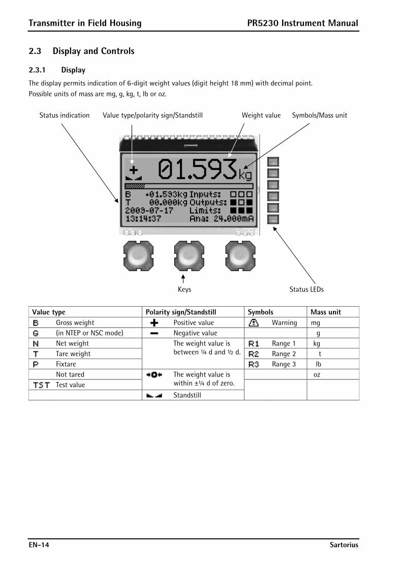
The display permits indication of 6-digit weight values (digit height 18 mm) with decimal point. Possible units of mass are mg, g, kg, t, lb or oz.
Status indication Value type/polarity sign/Standstill Weight value Symbols/Mass unit
Keys Status LEDs
Value type Polarity sign/Standstill Symbols Mass unit
Gross weight Positive value Warning mg
(in NTEP or NSC mode) Negative value g
Net weight Range 1 kg
Tare weight Range 2 t
Fixtare
The weight value is between ¼ d and ½ d.
Range 3 lb Not tared oz
Test value The weight value is
within ±¼ d of zero. Standstill
PR5230 Instrument Manual Transmitter in Field Housing
Sartorius EN-15
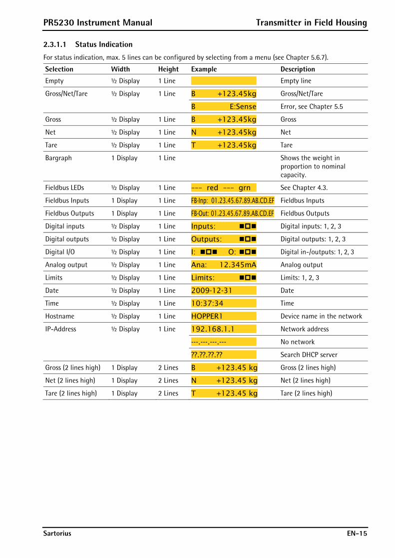
2.3.1.1 Status Indication
For status indication, max. 5 lines can be configured by selecting from a menu (see Chapter 5.6.7).
Selection Width Height Example Description
Empty ½ Display 1 Line Empty line
B +123.45kg Gross/Net/Tare Gross/Net/Tare ½ Display 1 Line
B E:Sense Error, see Chapter 5.5
Gross ½ Display 1 Line B +123.45kg Gross
Net ½ Display 1 Line N +123.45kg Net
Tare ½ Display 1 Line T +123.45kg Tare
Bargraph 1 Display 1 Line Shows the weight in proportion to nominal capacity.
Fieldbus LEDs ½ Display 1 Line ––– red ––– grn See Chapter 4.3.
Fieldbus Inputs 1 Display 1 Line FB-Inp: 01.23.45.67.89.AB.CD.EF Fieldbus Inputs
Fieldbus Outputs 1 Display 1 Line FB-Out: 01.23.45.67.89.AB.CD.EF Fieldbus Outputs
Digital inputs ½ Display 1 Line Inputs: Digital inputs: 1, 2, 3
Digital outputs ½ Display 1 Line Outputs: Digital outputs: 1, 2, 3
Digital I/O ½ Display 1 Line I: O: Digital in-/outputs: 1, 2, 3
Analog output ½ Display 1 Line Ana: 12.345mA Analog output
Limits ½ Display 1 Line Limits: Limits: 1, 2, 3
Date ½ Display 1 Line 2009-12-31 Date
Time ½ Display 1 Line 10:37:34 Time
Hostname ½ Display 1 Line HOPPER1 Device name in the network
192.168.1.1 Network address
---.---.---.--- No network
IP-Address ½ Display 1 Line
??.??.??.?? Search DHCP server
Gross (2 lines high) 1 Display 2 Lines B +123.45 kg Gross (2 lines high)
Net (2 lines high) 1 Display 2 Lines N +123.45 kg Net (2 lines high)
Tare (2 lines high) 1 Display 2 Lines T +123.45 kg Tare (2 lines high)
Transmitter in Field Housing PR5230 Instrument Manual
EN-16 Sartorius
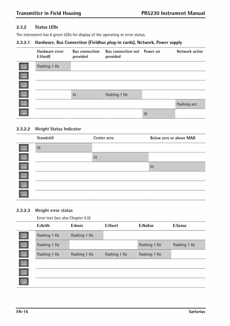
2.3.2 Status LEDs
The instrument has 6 green LEDs for display of the operating or error status.
2.3.2.1 Hardware, Bus Connection (Fieldbus plug-in cards), Network, Power supply
Hardware error E:HardE
Bus connection provided
Bus connection not provided
Power on Network active
flashing 1 Hz
lit flashing 1 Hz
flashing acc.
lit
2.3.2.2 Weight Status Indicator
Standstill Center zero Below zero or above MAX
lit
lit
lit
2.3.2.3 Weight error status
Error text (see also Chapter 5.5)
E:Arith E:Invrs E:Overl E:NoEoc E:Sense
flashing 1 Hz flashing 1 Hz
flashing 1 Hz flashing 1 Hz flashing 1 Hz
flashing 1 Hz flashing 1 Hz flashing 1 Hz flashing 1 Hz
PR5230 Instrument Manual Transmitter in Field Housing
Sartorius EN-17
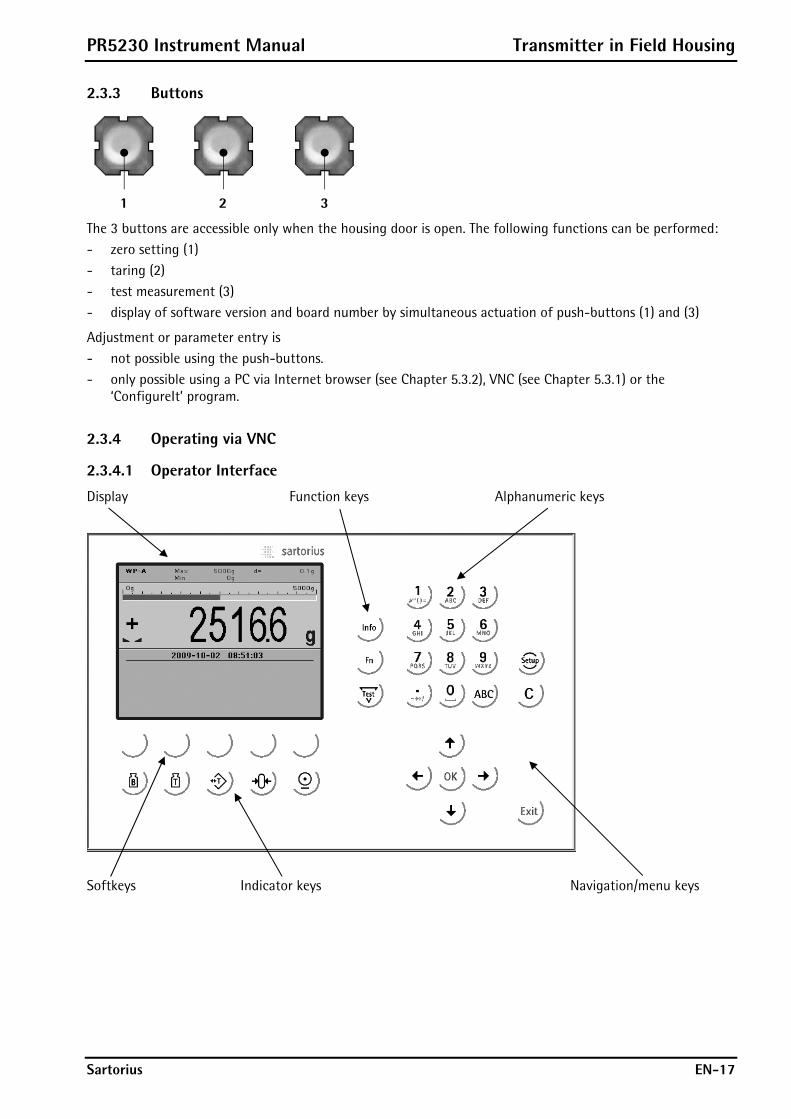
2.3.3 Buttons
1 2 3
The 3 buttons are accessible only when the housing door is open. The following functions can be performed: - zero setting (1) - taring (2) - test measurement (3) - display of software version and board number by simultaneous actuation of push-buttons (1) and (3)
Adjustment or parameter entry is - not possible using the push-buttons. - only possible using a PC via Internet browser (see Chapter 5.3.2), VNC (see Chapter 5.3.1) or the
‘ConfigureIt’ program.
2.3.4 Operating via VNC
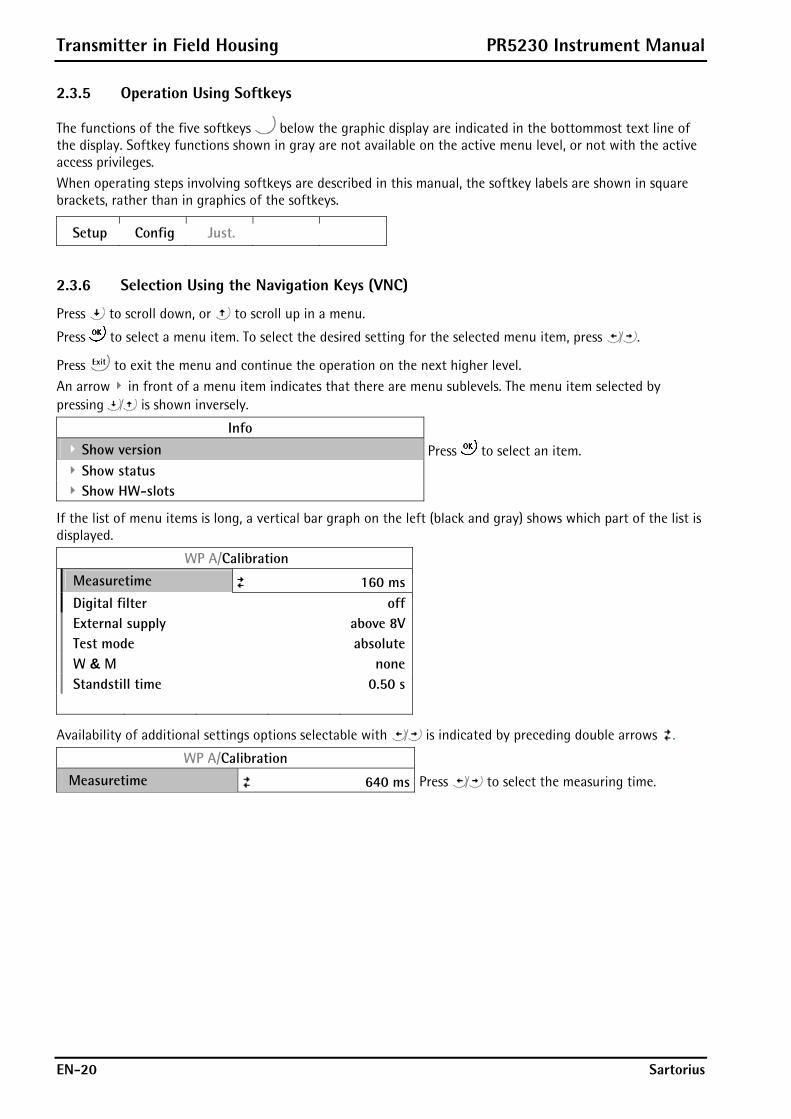
2.3.4.1 Operator Interface
Display Function keys Alphanumeric keys
Softkeys Indicator keys Navigation/menu keys

Transmitter in Field Housing PR5230 Instrument Manual
EN-18 Sartorius
The display shows weight values of up to 7 digits with decimal point and plus or minus sign.
Available mass units are mg, g, kg, t, lb or oz. lb and oz units are not permitted for use in legal metrology in the EU and EEC. The weight readout shows the current weight on a bar graph that indicates proportion of the maximum capacity (Max), with 0 on the left and 100 % on the right.
The following status indicators can be shown:
Status Description
Gross weight
In NTEP or NSC mode
Net weight (Net = gross – Tare)
Tare weight, fixtare
The display shows the test value without mass unit
Positive value
Negative value
The weight value is within ±¼ d of zero
The weight value is stable.
Value not permissible in legal metrology (e.g., 10-fold resolution).
2.3.4.2 Keys
The following tables show the basic meanings of symbols on the operator interface.
Indicator key Description
Display gross weight
Display tare weight
Taring; the current gross weight is stored in the tare memory, provided that: - weight value is stable. - indicator is not in error status (function dependent on configuration).
Sets gross weight to zero, provided that (function dependent on configuration): - weight value is stable. - weight is within zero setting range
Start printing.

PR5230 Instrument Manual Transmitter in Field Housing
Sartorius EN-19
Navigation key Description
Cursor moves to the right. Selection
Cursor moves to the left. Selection
Scroll up in the menu.
Scroll down in the menu.
Menu key Description
Softkey: select function
Backspace/delete
Exit from current menu; continue operation on next higher level.
Enter/confirm
Function key Description
Information on version number, fitted hardware,10-fold resolution
Without function
Test
Open the setup menu
Toggle to alphabetic input mode. During configuration, you can switch between the mass units by pressing this key.
Transmitter in Field Housing PR5230 Instrument Manual
EN-20 Sartorius
2.3.5 Operation Using Softkeys
The functions of the five softkeys below the graphic display are indicated in the bottommost text line of the display. Softkey functions shown in gray are not available on the active menu level, or not with the active access privileges. When operating steps involving softkeys are described in this manual, the softkey labels are shown in square brackets, rather than in graphics of the softkeys.
Setup Config Just.
2.3.6 Selection Using the Navigation Keys (VNC)
Press to scroll down, or to scroll up in a menu.
Press to select a menu item. To select the desired setting for the selected menu item, press .
Press to exit the menu and continue the operation on the next higher level. An arrow in front of a menu item indicates that there are menu sublevels. The menu item selected by pressing is shown inversely.
Info
Show version Press to select an item. Show status
Show HW-slots
If the list of menu items is long, a vertical bar graph on the left (black and gray) shows which part of the list is displayed.
WP A/Calibration
Measuretime 160 ms
Digital filter off External supply above 8V Test mode absolute W & M none Standstill time 0.50 s
Availability of additional settings options selectable with is indicated by preceding double arrows .
WP A/Calibration
Measuretime 640 ms Press to select the measuring time.

PR5230 Instrument Manual Transmitter in Field Housing
Sartorius EN-21
2.3.7 Tool Tip (VNC)
The 'tool tip' indicates valid value ranges or important properties in a pop-up window, see example:
This is a warning, that the zero tracking is not activated, if the Zerotrack time is set to 0.
Transmitter in Field Housing PR5230 Instrument Manual
EN-22 Sartorius
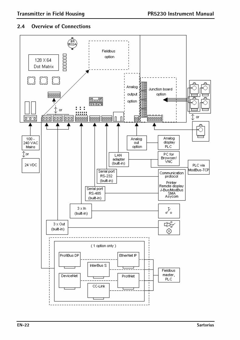
2.4 Overview of Connections
PR5230 Instrument Manual Transmitter in Field Housing
Sartorius EN-23
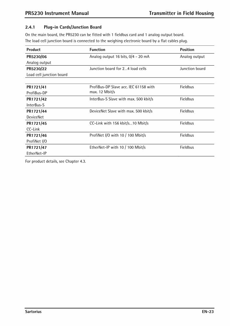
2.4.1 Plug-in Cards/Junction Board
On the main board, the PR5230 can be fitted with 1 fieldbus card and 1 analog output board. The load cell junction board is connected to the weighing electronic board by a flat cables plug.
Product Function Position
PR5230/06 Analog output
Analog output 16 bits, 0/4 - 20 mA Analog output
PR5230/22 Load cell junction board
Junction board for 2…4 load cells Junction board
PR1721/41 ProfiBus-DP
ProfiBus-DP Slave acc. IEC 61158 with max. 12 Mbit/s
Fieldbus
PR1721/42 InterBus-S
InterBus-S Slave with max. 500 kbit/s Fieldbus
PR1721/44 DeviceNet
DeviceNet Slave with max. 500 kbit/s Fieldbus
PR1721/45 CC-Link
CC-Link with 156 kbit/s…10 Mbit/s Fieldbus
PR1721/46 ProfiNet I/O
ProfiNet I/O with 10 / 100 Mbit/s Fieldbus
PR1721/47 EtherNet-IP
EtherNet-IP with 10 / 100 Mbit/s Fieldbus
For product details, see Chapter 4.3.

Options PR5230 Instrument Manual
EN-24 Sartorius
3 Options Designation Code no. Description Chapter
Analog/digital converter
Standard none
W1 Weighing electronic board 4.2.3 EX WE1 Weighing electronic board with intrinsically
safe load cell supply for operation of load cells/platforms in Zones 1 and 21
3.2
power supply Standard L0 Version 230 V 1.4.4.1 L8 Version 24 V 1.4.4.2 IP protection I66 IP66 Digital input DE1 Digital input, passive (external supply) 4.2.6.1 DE2 Digital input aktive (internal 12 V supply) 4.2.6.2 Digital output DA1 Digital output relay 4.2.8 DA2 Digital output Optocoupler 4.2.7 EX Zone Standard none Y2 Approval ATEX/EU, Zone 2/22 3.1 Interface Slot 1 Standard none C11 Analog output 16 bits, 0/4 - 20 mA 4.3.2 Interface Slot 2 Standard none C21 ProfiBus-DP 4.3.4 C22 InterBus-S 4.3.5 C24 DeviceNet 4.3.6 C25 CC-Link 4.3.7 C26 ProfiNet I/O 4.3.8 C27 EtherNet-IP 4.3.9 Interface Slot 3 Standard none C31 Load cell junction board 4.3.3 Connecting cable Standard none for network M39* Ethernet socket, RJ-45 plug, IP67 4.3.10 M40* Ethernet cable, 7m long,
metric cable gland, RJ-45 plug, industry version
4.3.11
* For the Builtin Ethernet interface only!
Instrument Option
The marking (e.g. PR5230-W1-L0-I66-DE1-DA1-C11-C31) of the instrument option is located on a label inside the instrument.
PR5230 Instrument Manual Options
Sartorius EN-25
3.1 Option Y2
3.1.1 Safety Instructions
Caution!
It is essential to observe the safety instruction in Chapter 16!
3.1.2 Description
PR5230 with option Y2 is only suitable for using within Ex areas Zone 2 and 22 (non conductive dust) according European directive 94/9/EG and related harmonized European standards (see also Chapter 16). The Ex design for Zone 2/22 see Chapter 16.
3.1.3 Marking
II 3G Ex nA nC IIC T4 II 3D Ex tD A22 IP6X T80°C SAG 09ATEX004X
See also Chapter 16.
3.1.4 Outputs
With option Y2 are following outputs possible: - Opto-decoupled outputs (option DA2): Technical Data see Chapter 14.5.8.2. - Relays (option DA1): Only external circuits with voltages up to 60 V AC or 75 V DC are allowed to be
connected to the relays, see Safety Instruction in Chapter 16.
3.1.5 In Connection with Option W1
Connected load cells or weighing platforms must be certified for use in Ex areas Zone 2 or Zone 22 and for load cell supply voltages of more than 13.2 V DC. When use - in Zone 2 observe gas group and temperature class. - in Zone 22 observe the allowed surface temperature.
3.1.6 In Connection with Option WE1
The combination Y2 and WE1 is also possible; see Ex design for Zone 2/22 and Zone 1/21 in Chapter 16.

Options PR5230 Instrument Manual
EN-26 Sartorius
3.1.7 Installation
The installation must be performed by qualified personnel in compliance with the applicable laws, regulations, ordinances and standards. In particular, the standards EN 60079-14 (gas) and EN 61241-14 (dust) must be taken into account. All cables to and from PR5230 have to be installed firmly. It is only allowed to connect instruments (not sparking during operation) to power circuits in Zone 2 which are suitable for Zone 2 and the local conditions at the operating location. Not used cable glands must be closed with ATEX approved screwings in order to secure IP65 protection.
Danger! Working at the switched on unit may be dangerous to life!
Disconnect the instrument from the supply voltage.
When removing covers or parts by means of tools, live parts or terminals may be exposed.
Capacitors in the unit may still be charged also after disconnecting the unit from all voltage sources.
3.1.8 Repairs/Cleaning/Maintenance
Warning!
In the Ex atmosphere it’s not permissible to mount/loose plug connectors or to change fuses!
Any modifications to the instrument (except by persons authorized by Sartorius) cause loss of conformity for use in Zone 2 and 22 hazardous areas and invalidate all guarantee claims. Similary, the instrument may only be opened by qualified and authorized persons. Repairs are subject to inspection and must be carried out at Sartorius. In case of defect or malfunction, please contact your local Sartorius dealer or service center for repair. When returning the instrument for repair, please include a precise and complete description of the problem. Instruments used in Zone 22 remove dust regulary. Dust layers >5 mm are not permitted. Maintenance work may be carried out only by a trained technician with expert knowledge of the hazards involved and the required precautions.
3.1.9 Environmental Conditions
Use the transmitter only within the temperature range of -10 °C…+40 °C. Avoid the inadmissible exposure of heat, cold, direct sunlight, UV radiation or vibration. Install the instrument in that way, that air circulation is possible and heat sources are sufficient far away.
PR5230 Instrument Manual Options
Sartorius EN-27
3.2 Option WE1
3.2.1 Safety Instructions
Caution!
It is essential to observe the safety instruction in Chapter 16!
3.2.2 Description
The option WE1 is used for an intrinsically safe interface of load cells or weighing platforms situated in a hazardous (Ex) area Zone 1 and 21 with PR5230 installed in a safe area according European directive 94/9/EG and related harmonized European standards (see also Chapter 16). The unit is designed for weighing applications requiring intrinsically safe interfacing. This is achieved by use of double provided current and voltage limiters in the supply circuit and voltage limiters in the analogue elektonic (weighing electronic board) of the PR5230 with option WE1.
The PR5230 with option WE1 provides the intrinsically safe interfacing of: - 1 voltage output for the supply of load cells or weighing platforms situated in Zone 1 or 21, - 1 measuring voltage input from Zone 1 or 21 and - 1 sense voltage input from Zone 1 or 21.
3.2.3 Marking
II (2) G [Ex ib] IIC II (2) D [Ex ib D] KEMA 10 ATEX 0065 X
See also Chapter 16.
3.2.4 Display
After switching on the instrument the following information is short-time displayed:
3.2.5 In Connection with Option Y2
The combination WE1 and Y2 is also possible; see Ex design for Zone 2/22 and Zone 1/21 in Chapter 16.
Options PR5230 Instrument Manual
EN-28 Sartorius
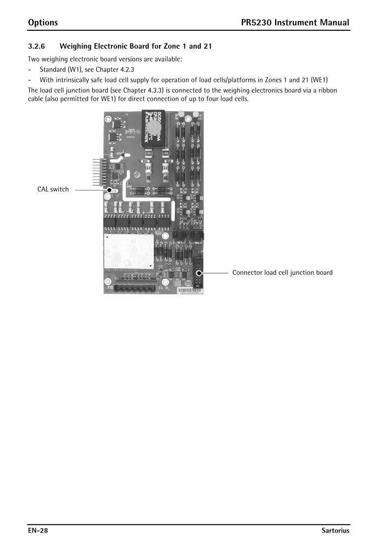
3.2.6 Weighing Electronic Board for Zone 1 and 21
Two weighing electronic board versions are available: - Standard (W1), see Chapter 4.2.3 - With intrinsically safe load cell supply for operation of load cells/platforms in Zones 1 and 21 (WE1) The load cell junction board (see Chapter 4.3.3) is connected to the weighing electronics board via a ribbon cable (also permitted for WE1) for direct connection of up to four load cells.
CAL switch
Connector load cell junction board

PR5230 Instrument Manual Options
Sartorius EN-29
3.2.7 Connection within the Ex Area
+ w
hite
+ re
d–
blac
k–
blue
+ gr
een
– gr
ey
PR52
30 w
ith o
ptio
n W
E1
PR16
25/6
0
PR61
30/6
5 S
Load
cel
l
Equi
pote
ntia
l bon
ding
con
duct
or
98
54
21
PR16
28/6
0 or
PR
5110
/60
12 V
+ –
ExA
rea
Non
Ex
Are
a
S1
S2
INO
UT
INO
UT
INO
UT
INO
UT
INO
UT
+
–
INO
UT
12
34
89
1011
INO
UT
~/+
~/–
SC
RE
EN
SC
RE
EN
TXE
RX
TX12
VIN
2IN
1
SC
RE
EN
SC
RE
EN
24 V
OU
T2O
UT1
BA
BA
TXG
ND
RX
BA
BA
RX
GN
DTX
-+
PE
24 V
DC
:or
LN
PE
230
VA
C:
24 V
DC23
0 V
AC
–
+
–
+
PE
N L
PR61
36In
terfa
ceR
S-4
22/4
85P
R16
04/0
0S
olde
r lin
k X
3:cl
osed
Sol
der l
ink
X7:
clos
ed
+M-M
+V+S
-S-V
GN
DA
Supply -
Sense +
Signal -
Screen
Sense -
Supply +
Signal +
IND
IND
IND
IND
IND
IND
IND
PR16
24
X301
GN
DA
J250
deliv
ery
stat
e, s
ee a
lso
chap
ter 3
.2.7
.3
Options PR5230 Instrument Manual
EN-30 Sartorius
3.2.8 Installation
3.2.8.1 General
The installation must be performed by qualified personnel in compliance with the applicable laws, regulations, ordinances and standards. In particular, the standards EN 60079-14 (gas) and EN 61241-14 (dust) must be taken into account. All cables to and from PR5230 have to be installed firmly. Not used cable glands must be closed with ATEX approved screwings in order to secure IP65 protection.
Danger! Working at the switched on unit may be dangerous to life!
Disconnect the instrument from the supply voltage.
When removing covers or parts by means of tools, live parts or terminals may be exposed.
Capacitors in the unit may still be charged also after disconnecting the unit from all voltage sources.
PR5230 Instrument Manual Options
Sartorius EN-31
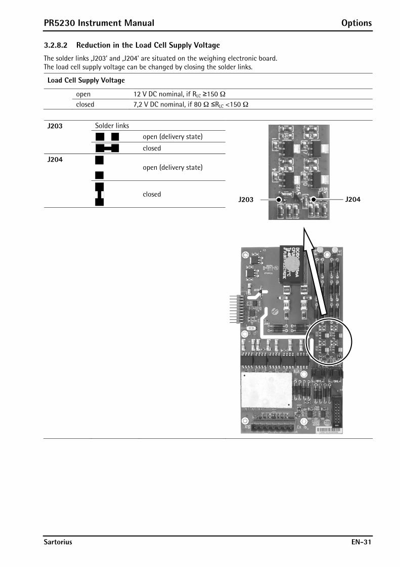
3.2.8.2 Reduction in the Load Cell Supply Voltage
The solder links ‚J203’ and ‚J204’ are situated on the weighing electronic board. The load cell supply voltage can be changed by closing the solder links.
Load Cell Supply Voltage
open 12 V DC nominal, if RLC ≥150 ¥ closed 7,2 V DC nominal, if 80 ¥ ≤RLC <150 ¥
Solder links
open (delivery state) J203
closed
open (delivery state)
J204
closed
J203 J204

Options PR5230 Instrument Manual
EN-32 Sartorius
3.2.8.3 Potential-free Load Cell Supply Voltage
The instrument with option WE1 will be delivered with an intrinsically safe circuit which is galvanically connected with the equipotential bonding (PA).
Jumper J250
At distances >50 m a potential-free load cell supply voltage is required. This is done as follows:
Cut the jumper J250 on the weighing electronic board.
Turn the remaining wire leads upward and cut them just above the board. Make sure that both contacts have a minimum distance of 2 mm and don’t touch other potentials.
If the jumper J250 is open, the intrinsically safe circuit is isolated from the housing (PA) at a minimum test voltage of 500 V.

PR5230 Instrument Manual Options
Sartorius EN-33
3.2.8.4 Potential Equalization
Possible compensatory currents between several conducting plant sections will be avoid by installing a potential equalization in the ex areas.
PR5230-WE1-…
Load CellsWägezellen
Junction BoxVerbindungskasten
Ex Area Zone 1/21Ex-Bereich Zone 1/21
Non Ex AreaKein Ex-Bereich
(1) (2) (1) (1) (2) (3)
(6) (6)
(A)(4)
(4) (4)
(A) (A) (A) (A) (A) (A)
(E)
(5)
(B)
(1)
Pos. Component Cross-section
(1) Conductor for additional potential equalization 4,0 mm² Cu (2) Conductor for potential equalization 6,0 mm² Cu (3) Conductor for potential equalization 10,0 mm² Cu (4) Main conductor for potential equalization 10,0 mm² Cu (5) Earthing conductor 10,0 mm² Cu (6) Load cell by-pass 10,0 mm² Cu (A) Sub potential equalization terminal (B) Main potential equalization terminal (E) To earth electrode
Options PR5230 Instrument Manual
EN-34 Sartorius
3.2.8.5 Screenings
Danger!
Incorrect connection of the connecting cable screens may have consequences of severe damage for personal and plant!
At distances >50 m the screen may only be connected at one end:
Connect the connecting cable screen to PR5230, see Chapter 4.2.4. Open the jumper J250 on the weighing electronic board, see Chapter 3.2.8.3. Load cells with cable screen connected to the housing and using the
junction box PR6130/64 Sa: Connect the connecting cable screen, see Installation Manual. Open the link above the Sense terminal block on the board of the junction, see
Installation Manual.
Load cells with cable screen connected to the housing and using the junction box PR6130/65 S: Don’t connect the connecting cable screen, see also Chapter 3.2.7.
3.2.9 Repairs/Cleaning/Maintenance
Warning!
In PR5230 with option WE1 it’s not permissible to mount/loose plug connectors or to change fuses!
Repairs are subject to inspection and must be carried out at Sartorius. In case of defect or malfunction, please contact your local Sartorius dealer or service center for repair. When returning the instrument for repair, please include a precise and complete description of the problem. Maintenance work may be carried out only by a trained technician with expert knowledge of the hazards involved and the required precautions.
PR5230 Instrument Manual Options
Sartorius EN-35
3.2.10 Technical Data
Note: Further technical data of PR5230 see Chapter 14.
3.2.10.1 General Data
Accuracy <10000 e (Klasse III) according to OIML R76/EN 45501 Connection for the non Ex area via 4mm2 screw terminals
Connection for the Ex area via 4mm2 screw terminals Intrinsically safe output Protection class Ex ib IIC Potential equalization Via screw terminal PE, see Chapter 3.2.8.4
3.2.10.2 Power Connection 230 V AC
Supply voltage 100…230 V AC ±10 % Power consumption 16 VA Frequency 50…60 Hz ±2 Hz
3.2.10.3 Power Connection 24 V DC
Supply voltage 24 V DC ±10 % Power consumption 12 W
3.2.10.4 Output Parameter (intrinsically safe) for the Connection of Load Cells/Junction Box/Weighing Platforms
The connection will be done via 7-pin plug (marked with ‚X100’ and ‚Exib’) on the weighing electronic board.
Uo 21,0 V between the lines lo 143 mA Po 1,55 W Co 188 nF between the lines Lo 0,12 mH

Options PR5230 Instrument Manual
EN-36 Sartorius
3.2.10.5 Load Cells
Supply voltage ±6 V DC (nominal)/ 96 mA Max. 4 load cells of 650 each, connected in parallel (= 162,5 ¥)
±3,6 V DC (nominal)/ 96 mA Max. 8 load cells of 650 each, connected in parallel (= 81,3 ¥) or 4 load cells of 350 each, connected in parallel (= 87,5 ¥)
Tolerance range ±5,8…±6,2 V DC; ±3,4…±3,8 V DC Max. current 100 mA short circuit
Measuring voltage Vmeas Max. 36 mV (differential) Sense voltage Vsense ±6 V nominal (with ref. to ground) ±3,6 V nominal (with ref. to ground)
3.2.10.6 Connection Cable
Length of the connection cable between junction box and PR5230
Type PR6135, PR6135A Max. 200 m – length of the load cell cable
Length of the connection cable between weighing platform and PR5230
Type LiYCY Max. 200 m
3.2.10.7 Environmental Conditions
Use the transmitter only within the temperature range of -10 °C…+40 °C. Avoid the inadmissible exposure of heat, cold, direct sunlight, UV radiation or vibration. Install the instrument in that way, that air circulation is possible and heat sources are sufficient far away.

PR5230 Instrument Manual Installing the Instrument and Plug-in Cards
Sartorius EN-37
4 Installing the Instrument and Plug-in Cards Before starting work, please read Chapter 1 and follow all instructions! Further procedures:
Check the consignment: unpack the components specific to the application.
Safety check: inspect all components for damage.
Make sure the on-site installation is correct and complete including cables, e.g. power cable fuse protection, load cells, junction box, data cable, console/cabinet, etc.
If necessary, mount the plug-in cards (instrument must be disconnected from all voltage sources).
Follow the instructions for installation of the unit relating to application, safety, ventilation, sealing and environmental influences!
Connect the cable from junction box or platform/load cell.
If applicable: connect other data cables, power cable, etc.
Connect the instrument power cable.
Check the installation.
4.1 Mechanical Preparation Have all required parts, technical documents and tools at hand for mounting. Secure the cable at the place of installation; e.g., using cable ties. Remove the insulation from the cable ends, keep the strands short and fit them with ferrules
4.2 Hardware Construction The main electronics circuitry is accommodated on the following PCBs: - Main board - Display board - Weighing electronic board
Display board Main board Weighing electronic board
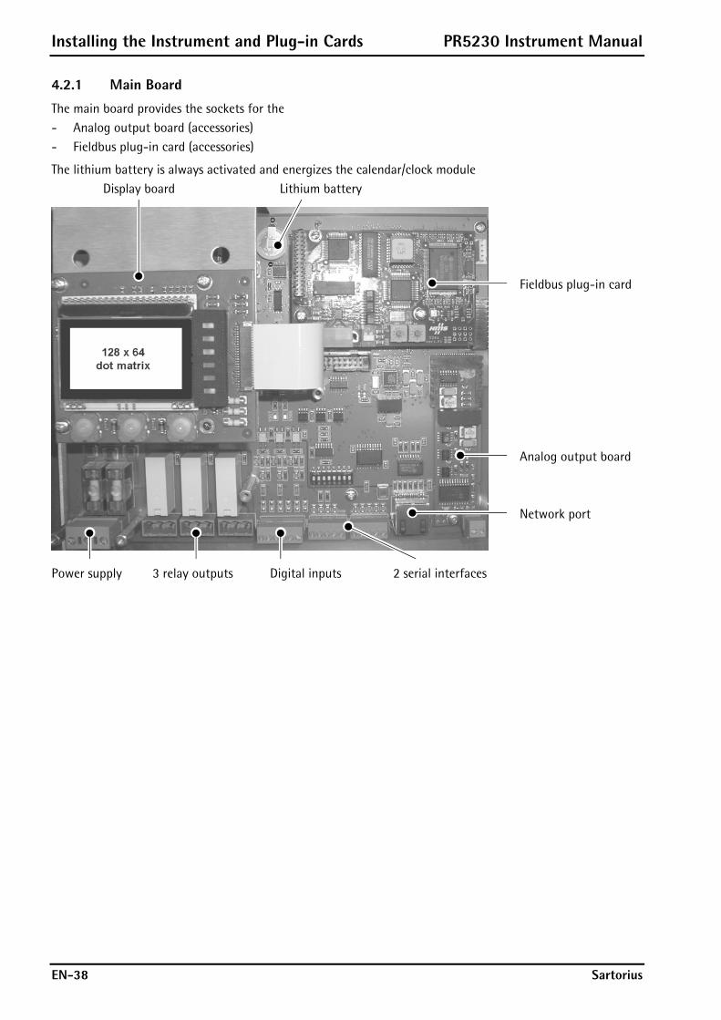
Installing the Instrument and Plug-in Cards PR5230 Instrument Manual
EN-38 Sartorius
4.2.1 Main Board
The main board provides the sockets for the - Analog output board (accessories) - Fieldbus plug-in card (accessories)
The lithium battery is always activated and energizes the calendar/clock module Display board Lithium battery
Fieldbus plug-in card Analog output board Network port
Power supply 3 relay outputs Digital inputs 2 serial interfaces
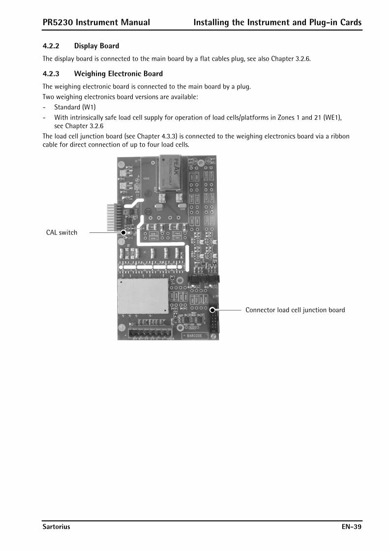
PR5230 Instrument Manual Installing the Instrument and Plug-in Cards
Sartorius EN-39
4.2.2 Display Board
The display board is connected to the main board by a flat cables plug, see also Chapter 3.2.6.
4.2.3 Weighing Electronic Board
The weighing electronic board is connected to the main board by a plug. Two weighing electronics board versions are available: - Standard (W1) - With intrinsically safe load cell supply for operation of load cells/platforms in Zones 1 and 21 (WE1),
see Chapter 3.2.6 The load cell junction board (see Chapter 4.3.3) is connected to the weighing electronics board via a ribbon cable for direct connection of up to four load cells.
CAL switch
Connector load cell junction board
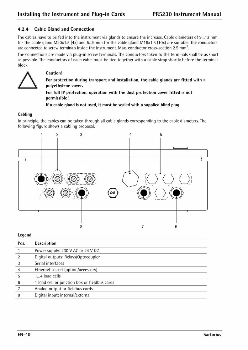
Installing the Instrument and Plug-in Cards PR5230 Instrument Manual
EN-40 Sartorius
4.2.4 Cable Gland and Connection
The cables have to be fed into the instrument via glands to ensure the increase. Cable diameters of 9…13 mm for the cable gland M20x1.5 (4x) and 5…9 mm for the cable gland M16x1.5 (10x) are suitable. The conductors are connected to screw terminals inside the instrument. Max. conductor cross-section 2.5 mm2. The connections are made via plug-in screw terminals. The conductors taken to the terminals shall be as short as possible. The conductors of each cable must be tied together with a cable strap shortly before the terminal block.
Caution! For protection during transport and installation, the cable glands are fitted with a polyethylene cover. For full IP protection, operation with the dust protection cover fitted is not permissible! If a cable gland is not used, it must be sealed with a supplied blind plug.
Cabling In principle, the cables can be taken through all cable glands corresponding to the cable diameters. The following figure shows a cabling proposal.
1 2 3 4 5
8 7 6
Legend
Pos. Description
1 Power supply: 230 V AC or 24 V DC 2 Digital outputs: Relays/Optocoupler 3 Serial interfaces 4 Ethernet socket (option/accessory) 5 1…4 load cells 6 1 load cell or junction box or fieldbus cards 7 Analog output or fieldbus cards 8 Digital input: internal/external

PR5230 Instrument Manual Installing the Instrument and Plug-in Cards
Sartorius EN-41
Mounting the Cable
Caution! The connection of the cable screen of the fieldbus cards: essential see according Chapter 4.3.4 …4.3.9!
1 2 3 4 5 6
Caution! The cable screen (4) must be connected in the metal sleeve (6) of the cable gland. Don’t take the screen (4) into the unit! Before, during and after installation, make sure that the sealing ring is seated correctly.
Remove the (screw) cap (1).
Slide cap (1) and plastic cone (3) over the cable (2).
Take the cable (5) through the metal sleeve (6).
Fold the cable screen (4) over the lower part of the plastic cone (3) (approx. 10 mm).
Connect the cable conductors.
Tighten the (screw) cap (1).
Tighten metal sleeve (6) inclusive o-ring by lock nut (inside the housing).
Caution! Regularly check the cable gland for tightness and re-tighten it, if necessary.

Installing the Instrument and Plug-in Cards PR5230 Instrument Manual
EN-42 Sartorius
4.2.5 Network Port
The network port is built in as standard equipment. The port contains powerful TCP/IP connection circuitry with transfer rates of 10 or 100 Mbit/sec. Function checking is possible via the LED to the right of the display (act) or via the LED in the RJ 45 socket when the housing is open.
Transfer rate 10 Mbit/sec, 100 Mbit/sec, full/half duplex, auto-detection
Connection method Point to point Cable Pre-fabricated cable with M20 cable
gland Cable impedance 150 ¥
Electrical isolation Yes
Cable length Max. 7 m
Connection RJ-45 socket inside the housing
Remote operation of the PR5230 from the PC is possible; install VNC program Release 3.3.7* on the PC. For setting the network address, see Chapter 5.2.2. * Sartorius guarantees the functionality only if this version is
used!
4.2.6 Optocoupler Inputs
The main board has 3 digital inputs for process control, electrically isolated by optocouplers, each bipolar potential-free.
Number of inputs 3 (CH 1, CH 2, CH 3 ) Input signal Logic 0: 0 ... 5 V DC or open
Logic 1: 10 ... 28 V DC Internal 12 V DC supply or external supply required.
Input current <5 mA @ 24 V <11 mA @ 12 V Protected against incorrect polarity.
Electrical isolation Via optocoupler, internal supply is potential-free.
Connection Plug-in 6-pin screw terminal block, conductor cross-section max. 1.5 mm²
Cable Shielded, max. 50 m. The cable screen must be connected in the sleeve of the cable gland!
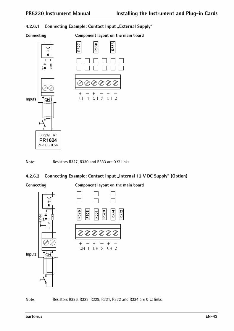
PR5230 Instrument Manual Installing the Instrument and Plug-in Cards
Sartorius EN-43
4.2.6.1 Connecting Example: Contact Input „External Supply“
Connecting Component layout on the main board
Note: Resistors R327, R330 and R333 are 0 ¥ links.
4.2.6.2 Connecting Example: Contact Input „Internal 12 V DC Supply” (Option)
Connecting Component layout on the main board
Note: Resistors R326, R328, R329, R331, R332 and R334 are 0 ¥ links.
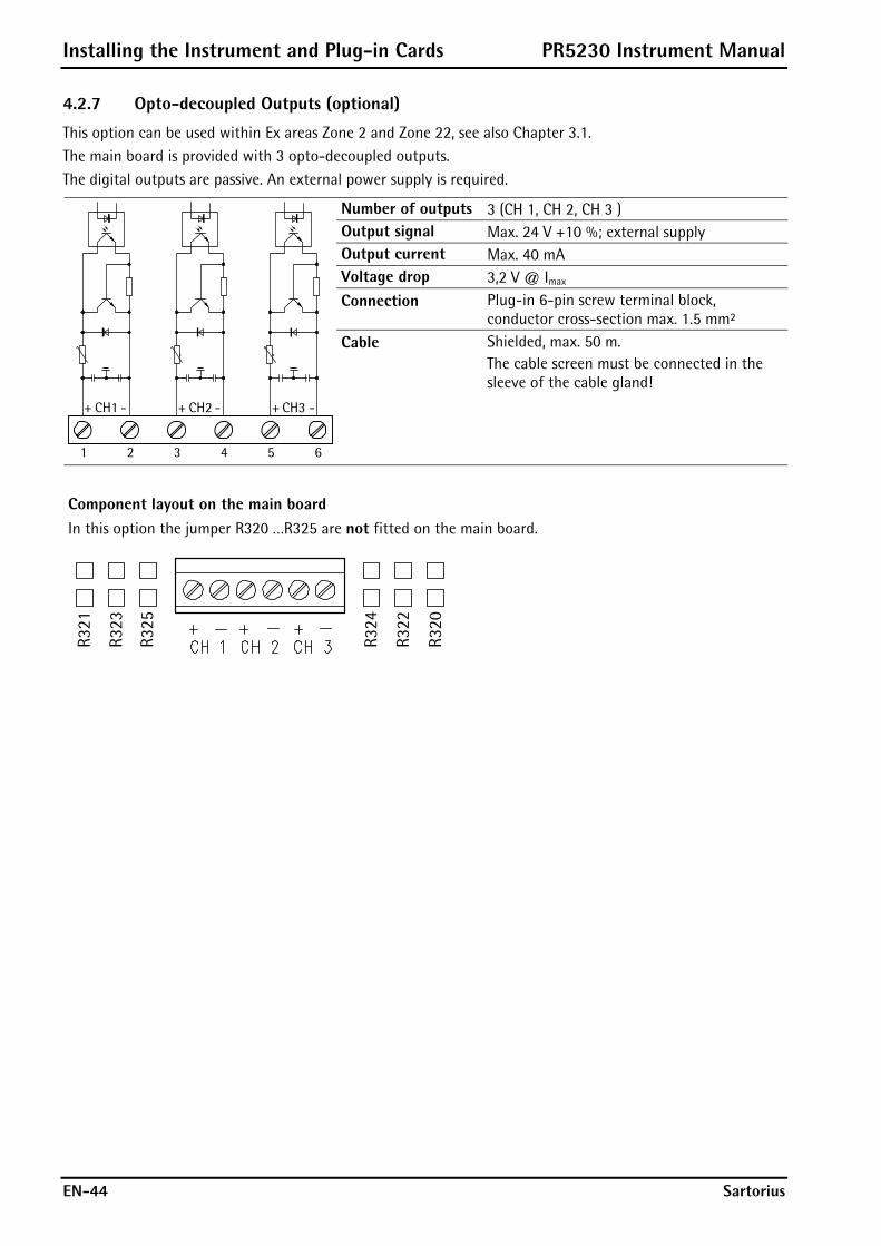
Installing the Instrument and Plug-in Cards PR5230 Instrument Manual
EN-44 Sartorius
4.2.7 Opto-decoupled Outputs (optional)
This option can be used within Ex areas Zone 2 and Zone 22, see also Chapter 3.1. The main board is provided with 3 opto-decoupled outputs. The digital outputs are passive. An external power supply is required.
Number of outputs 3 (CH 1, CH 2, CH 3 ) Output signal Max. 24 V +10 %; external supply Output current Max. 40 mA Voltage drop 3,2 V @ Imax Connection Plug-in 6-pin screw terminal block,
conductor cross-section max. 1.5 mm²
-CH1+ -CH2+ -CH3+
4 5321 6
Cable Shielded, max. 50 m. The cable screen must be connected in the sleeve of the cable gland!
Component layout on the main board In this option the jumper R320 …R325 are not fitted on the main board.
R321
R323
R325
R324
R322
R320
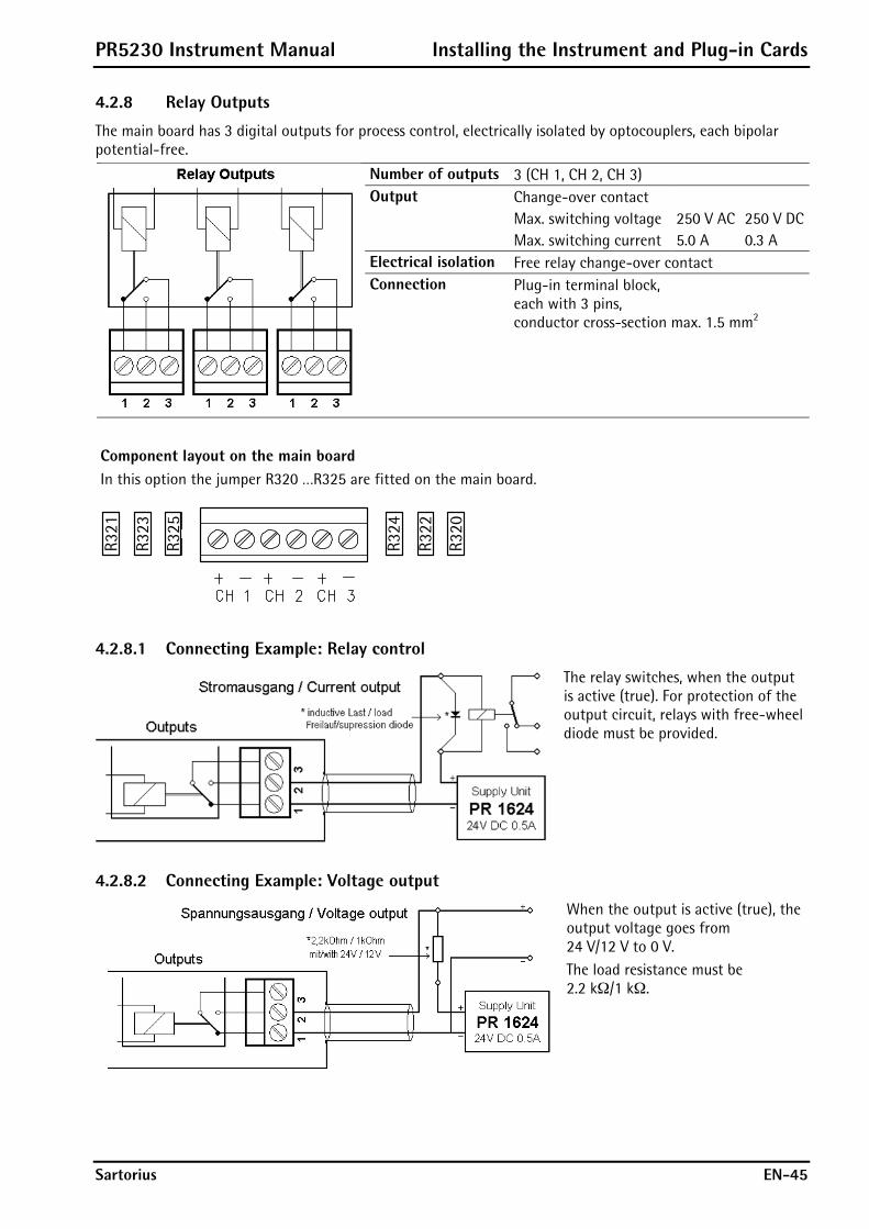
PR5230 Instrument Manual Installing the Instrument and Plug-in Cards
Sartorius EN-45
4.2.8 Relay Outputs
The main board has 3 digital outputs for process control, electrically isolated by optocouplers, each bipolar potential-free.
Number of outputs 3 (CH 1, CH 2, CH 3) Output Change-over contact
Max. switching voltage Max. switching current
250 V AC5.0 A
250 V DC0.3 A
Electrical isolation Free relay change-over contact Connection Plug-in terminal block,
each with 3 pins, conductor cross-section max. 1.5 mm2
Component layout on the main board In this option the jumper R320 …R325 are fitted on the main board.
R321
R323
R325
R324
R322
R320
4.2.8.1 Connecting Example: Relay control
The relay switches, when the output is active (true). For protection of the output circuit, relays with free-wheel diode must be provided.
4.2.8.2 Connecting Example: Voltage output
When the output is active (true), the output voltage goes from 24 V/12 V to 0 V. The load resistance must be 2.2 k¥/1 k¥.

Installing the Instrument and Plug-in Cards PR5230 Instrument Manual
EN-46 Sartorius
4.2.9 Interface RS-485
The instrument is provided with a built-in RS-485/422 interface. When mounting, the RS-485 interface must be configured by DIL switch S401 on the card. Using RS-485 is compulsory with a multi-point connection (Tristate status). The RS-485 interface can be used also for point-to-point connection.
Connection 5-pin plug-in terminal block Number of channels 1 RS-485 Type Full duplex Transfer rate 300…19,200 bit/sec Signals TxA, RxA, TxB, RxB Electrical isolation Yes Cable length Max. 1000 m
Cable type shielded twisted pair (e.g. LifYCY 3x2x0.20), 1 pair of wires for GND
DIL switch S401 Block diagram RS-485
TxBRxD/TxD-P
RxD/TxD-N TxA
RxB
RxA
4
5
3
2
1
GND
S4
S1
S2S6S7
S3
1K6
1K6
120
120
S5
DC
DC
1 2 3 4 5 6 7 8
ON DIP
S Function Settings for RS-485 1 Rx bus termination OFF: not connected ON: (RxA 120 ¥ RxB) 2 Rx pull-up resistor OFF: not connected ON: (RxB 1K6 ¥ +V) 3 Rx pull-down resistor OFF: not connected ON: (RxA 1K6 ¥ -V) 4 Tx/Rx bus termination OFF: not connected ON: (TxA 120 ¥ TxB) 5 Change-over 2- / 4-wire OFF: 4-wire ON: 2-wire 6 Rx enable OFF: Rx disabled, if Tx enabled:
S7 must be ON. ON: Rx immer enabled: For
4-wire S7 must be OFF. 7 Tx enable/Rx disable (2-wire) OFF: S6 must be ON. ON: S6 must be OFF. 8 n. c. no function
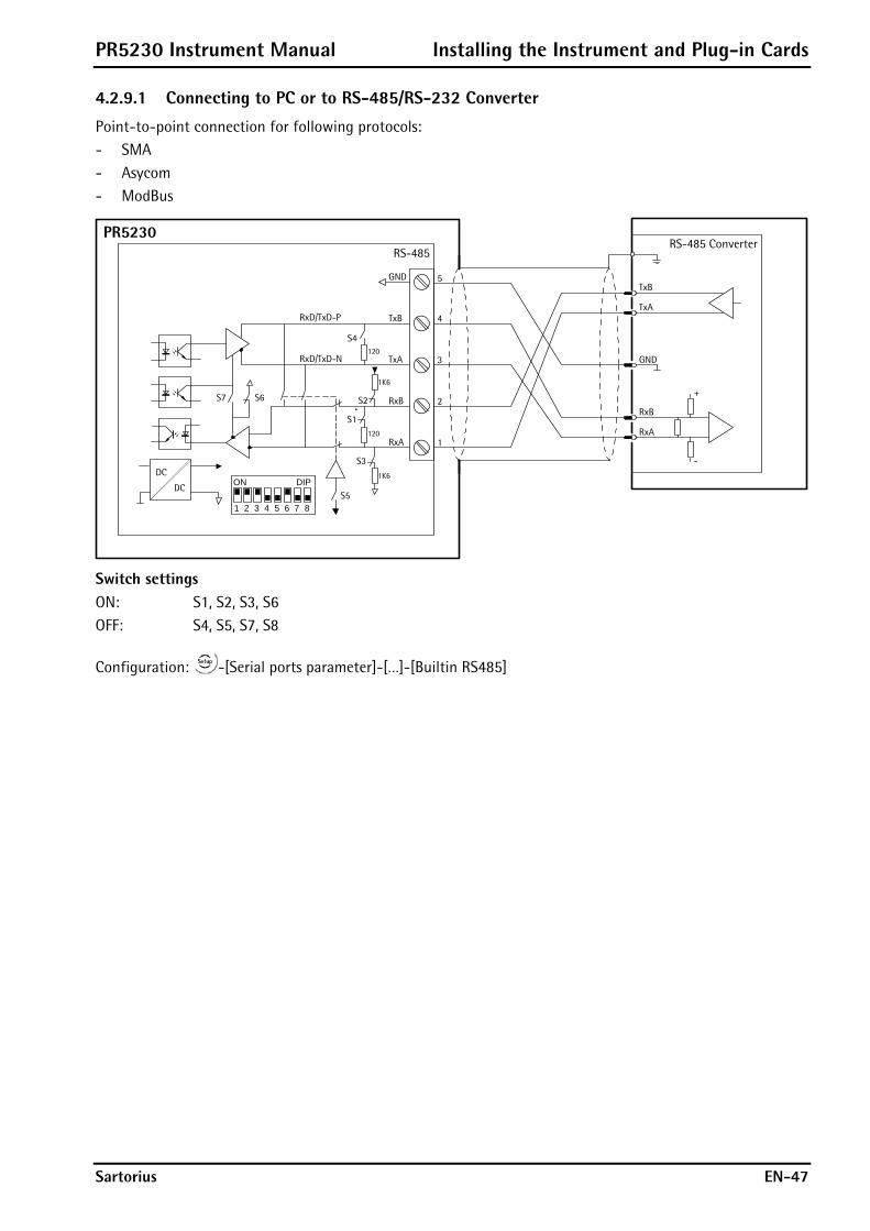
PR5230 Instrument Manual Installing the Instrument and Plug-in Cards
Sartorius EN-47
4.2.9.1 Connecting to PC or to RS-485/RS-232 Converter
Point-to-point connection for following protocols: - SMA - Asycom - ModBus
RS-485
PR5230RS-485 Converter
TxB
TxA
RxB
RxA
GND
+
-
TxBRxD/TxD-P
RxD/TxD-N TxA
RxB
RxA
4
5
3
2
1
GND
S4
S1
S2S6S7
S3
1K6
1K6
120
120
S5
DC
DC
1 2 3 4 5 6 7 8
ON DIP
Switch settings ON: S1, S2, S3, S6 OFF: S4, S5, S7, S8
Configuration: -[Serial ports parameter]-[…]-[Builtin RS485]

Installing the Instrument and Plug-in Cards PR5230 Instrument Manual
EN-48 Sartorius
4.2.9.2 Connecting several PR5230 to PC or to RS-485/RS-232 Converter
Connection of the Asycom protocol.
RS-485
PR5230RS-485 Converter
TxB
TxA
RxB
RxA
GND
RS-485
PR5230
RS-485
PR5230
Switch settings/SchalterstellungenON: S6OFF: S1, S2, S3, S4, S5, S7, S8
Switch settings/SchalterstellungenON: S6OFF: S1, S2, S3, S4, S5, S7, S8
Switch settings/SchalterstellungenON: S1, S2, S3, S6OFF: S4, S5, S7, S8
TxBRxD/TxD-P
RxD/TxD-N TxA
RxB
RxA
4
5
3
2
1
GND
S4
S1
S2S6S7
S3
1K6
1K6
120
120
S5
DC
DC
1 2 3 4 5 6 7 8
ON DIP
TxBRxD/TxD-P
RxD/TxD-N TxA
RxB
RxA
4
5
3
2
1
GND
S4
S1
S2S6S7
S3
1K6
1K6
120
120
S5
DC
DC
1 2 3 4 5 6 7 8
ON DIP
TxBRxD/TxD-P
RxD/TxD-N TxA
RxB
RxA
4
5
3
2
1
GND
S4
S1
S2S6S7
S31K6
1K6
120
120
S5
DC
DC
1 2 3 4 5 6 7 8
ON DIP
+
-
Configuration: -[Serial ports parameter]-[Asycom]-[Builtin RS485]

PR5230 Instrument Manual Installing the Instrument and Plug-in Cards
Sartorius EN-49
4.2.9.3 Connecting a PR1627 Remote Display
Four-wire transmission, point to point, full duplex (simultaneous sending and receiving possible) with PR1627/00 remote display.
RS-485
PR5230
PR1604
TxB
TxA
RxB
RxA
GND
4
5
8
9
3
DC
DC
X7
X6
X5
X3 X4
PR1627/00
TxBRxD/TxD-P
RxD/TxD-N TxA
RxB
RxA
4
5
3
2
1
GND
S4
S1
S2S6S7
S31K6
1K6
120
120
S5
DC
DC
1 2 3 4 5 6 7 8
ON DIP
Switch settings Solder links ON: S1, S2, S3, S6 closed: X3, X4, X5, X7 OFF: S4, S5, S7, S8 opened: X6
Configuration: -[Serial ports parameter]-[Remote display]-[Builtin RS485]

Installing the Instrument and Plug-in Cards PR5230 Instrument Manual
EN-50 Sartorius
4.2.9.4 Connecting a PR1628 Remote Display to several PR5230
RS-485
PR5230
RS-485
PR5230
RS-485
PR5230
Switch settings/SchalterstellungenON: S6OFF: S1, S2, S3, S4, S5, S7, S8
Solder links/LötbrückenClosed/geschlossen: X3, X4, X5, X7Open/geöffnet: X6
Switch settings/SchalterstellungenON: S6OFF: S1, S2, S3, S4, S5, S7, S8
Switch settings/SchalterstellungenON: S1, S2, S3, S6OFF: S4, S5, S7, S8
PR1604
TxB
TxA
RxB
RxA
GND
4
5
8
9
3
DC
DC
X7
X6
X5
X3 X4
PR1628/00
TxBRxD/TxD-P
RxD/TxD-N TxA
RxB
RxA
4
5
3
2
1
GND
S4
S1
S2S6S7
S31K6
1K6
120
120
S5
DC
DC
1 2 3 4 5 6 7 8
ON DIP
TxBRxD/TxD-P
RxD/TxD-N TxA
RxB
RxA
4
5
3
2
1
GND
S4
S1
S2S6S7
S3
1K6
1K6
120
120
S5
DC
DC
1 2 3 4 5 6 7 8
ON DIP
TxBRxD/TxD-P
RxD/TxD-N TxA
RxB
RxA
4
5
3
2
1
GND
S4
S1
S2S6S7
S3
1K6
1K6
120
120
S5
DC
DC
1 2 3 4 5 6 7 8
ON DIP
Configuration: -[Serial ports parameter]-[Remote display]-[Builtin RS485]-[Param]-[Mode: multiple transmitters]

PR5230 Instrument Manual Installing the Instrument and Plug-in Cards
Sartorius EN-51
4.2.9.5 Connecting several PR1628 Remote Displays
Connection of several PR1628 remote displays over RS-485, 4-wire, full-duplex (simultaneous sending and receiving possible).
RS-485
PR5230
Switch settings/SchalterstellungenON: S1, S2, S3, S6OFF: S4, S5, S7, S8
Solder links/LötbrückenClosed/geschlossen:Open/geöffnet: X3, X4, X5, X6, X7
PR1604
TxB
TxA
RxB
RxA
GND
4
5
8
9
3
DC
DC
X7
X6
X5
X3 X4
PR1628/00
Solder links/LötbrückenClosed/geschlossen:Open/geöffnet: X3, X4, X5, X6, X7
PR1604
TxB
TxA
RxB
RxA
GND
4
5
8
9
3
DC
DC
X7
X6
X5
X3 X4
PR1628/00
Solder links/LötbrückenClosed/geschlossen: X3, X4, X5Open/geöffnet: X6, X7
PR1604
TxB
TxA
RxB
RxA
GND
4
5
8
9
3
DC
DC
X7
X6
X5
X3 X4
PR1628/00
TxBRxD/TxD-P
RxD/TxD-N TxA
RxB
RxA
4
5
3
2
1
GND
S4
S1
S2S6S7
S3
1K6
1K6
120
120
S5
DC
DC
1 2 3 4 5 6 7 8
ON DIP
Configuration: -[Serial ports parameter]-[Remote display]-[Builtin RS485]
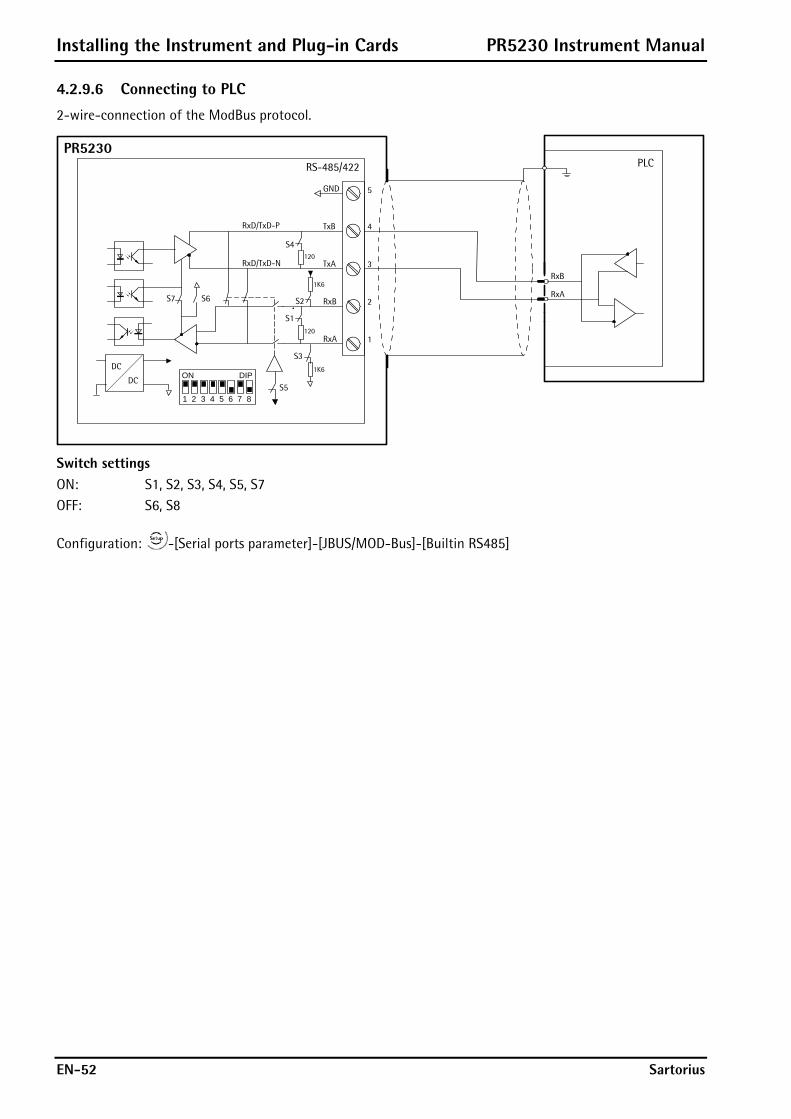
Installing the Instrument and Plug-in Cards PR5230 Instrument Manual
EN-52 Sartorius
4.2.9.6 Connecting to PLC
2-wire-connection of the ModBus protocol.
RS-485/422
PR5230PLC
RxB
RxA
TxBRxD/TxD-P
RxD/TxD-N TxA
RxB
RxA
4
5
3
2
1
GND
S4
S1
S2S6S7
S3
1K6
1K6
120
120
S5
DC
DC
1 2 3 4 5 6 7 8
ON DIP
Switch settings ON: S1, S2, S3, S4, S5, S7 OFF: S6, S8
Configuration: -[Serial ports parameter]-[JBUS/MOD-Bus]-[Builtin RS485]

PR5230 Instrument Manual Installing the Instrument and Plug-in Cards
Sartorius EN-53
4.2.9.7 Connecting several PR5230 to PLC
2-wire-connection of the ModBus protocol.
RS-485
PR5230
RS-485
PR5230
RS-485
PR5230
Switch settings/SchalterstellungenON: S1, S2, S3, S5, S7OFF: S4, S6, S8
Switch settings/SchalterstellungenON: S1, S2, S3, S5, S7OFF: S4, S6, S8
Switch settings/SchalterstellungenON: S1, S2, S3, S4, S5, S7OFF: S6, S8
PLC
RxB
RxA
TxBRxD/TxD-P
RxD/TxD-N TxA
RxB
RxA
4
5
3
2
1
GND
S4
S1
S2S6S7
S31K6
1K6
120
120
S5
DC
DC
TxBRxD/TxD-P
RxD/TxD-N TxA
RxB
RxA
4
5
3
2
1
GND
S4
S1
S2S6S7
S3
1K6
1K6
120
120
S5
DC
DC
TxBRxD/TxD-P
RxD/TxD-N TxA
RxB
RxA
4
5
3
2
1
GND
S4
S1
S2S6S7
S31K6
1K6
120
120
S5
DC
DC
1 2 3 4 5 6 7 8
ON DIP
1 2 3 4 5 6 7 8
ON DIP
1 2 3 4 5 6 7 8
ON DIP
Configuration: -[Serial ports parameter]-[JBUS/MOD-Bus]-[Builtin RS485]
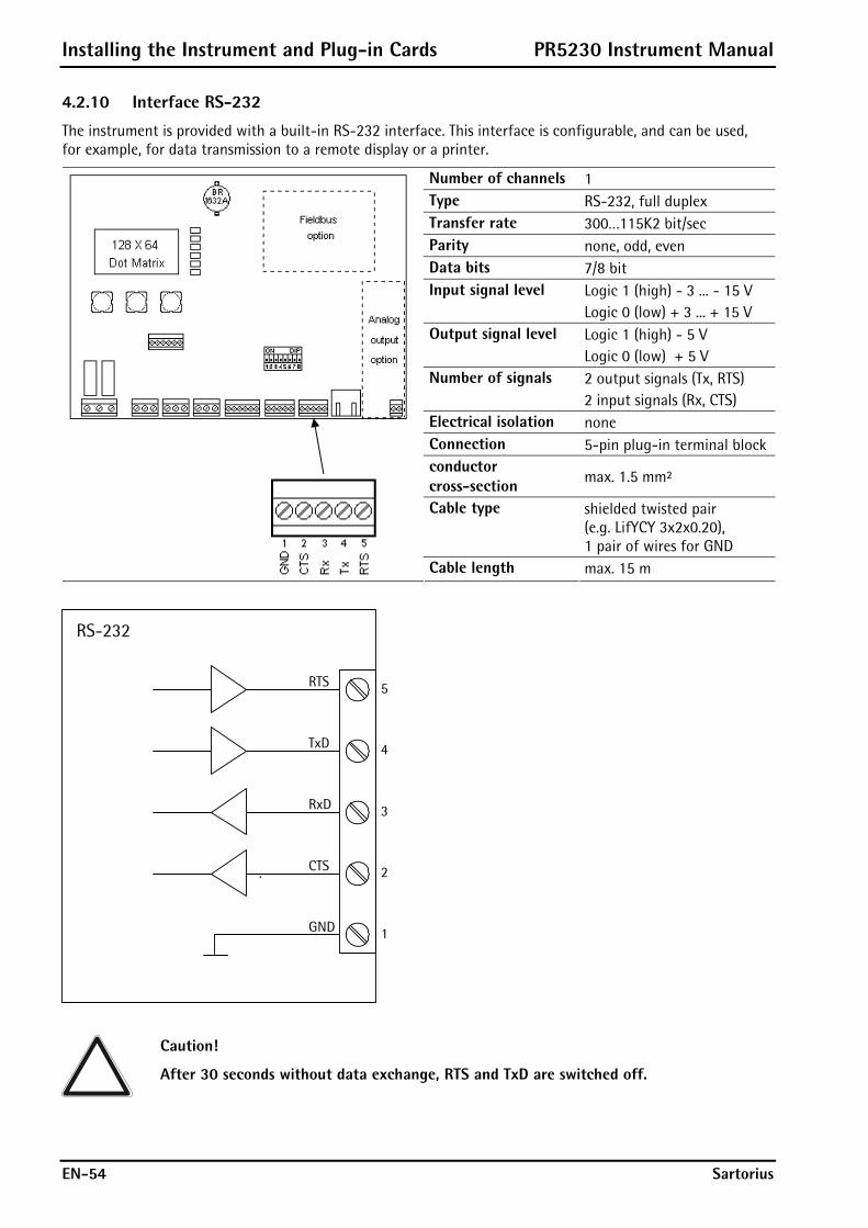
Installing the Instrument and Plug-in Cards PR5230 Instrument Manual
EN-54 Sartorius
4.2.10 Interface RS-232
The instrument is provided with a built-in RS-232 interface. This interface is configurable, and can be used, for example, for data transmission to a remote display or a printer.
Number of channels 1 Type RS-232, full duplex Transfer rate 300…115K2 bit/sec Parity none, odd, even Data bits 7/8 bit Input signal level Logic 1 (high) - 3 ... - 15 V
Logic 0 (low) + 3 ... + 15 V Output signal level Logic 1 (high) - 5 V
Logic 0 (low) + 5 V Number of signals 2 output signals (Tx, RTS)
2 input signals (Rx, CTS) Electrical isolation none Connection 5-pin plug-in terminal block conductor cross-section max. 1.5 mm²
Cable type shielded twisted pair (e.g. LifYCY 3x2x0.20), 1 pair of wires for GND
Cable length max. 15 m
TxD
RxD
CTS
GND
4
5
3
2
1
RTS
RS-232
Caution!
After 30 seconds without data exchange, RTS and TxD are switched off.
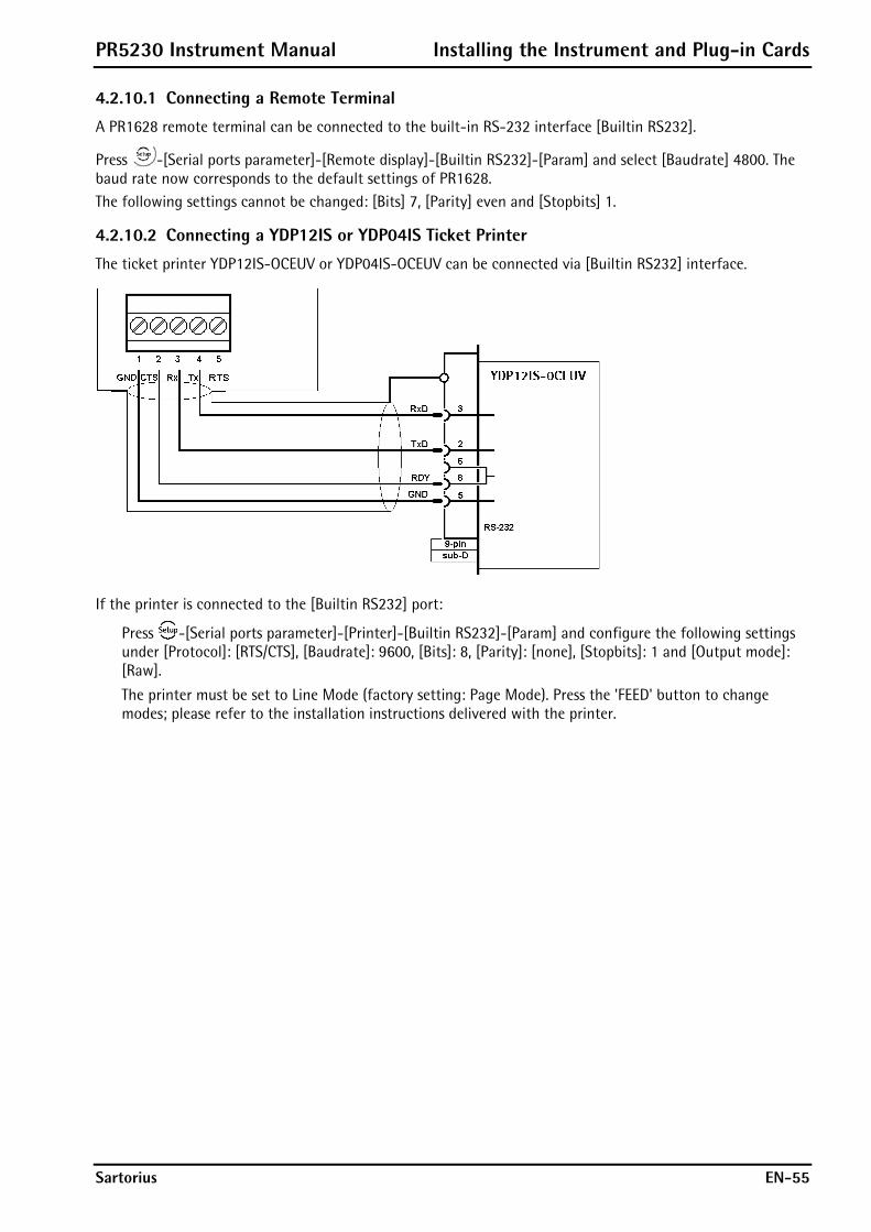
PR5230 Instrument Manual Installing the Instrument and Plug-in Cards
Sartorius EN-55
4.2.10.1 Connecting a Remote Terminal
A PR1628 remote terminal can be connected to the built-in RS-232 interface [Builtin RS232].
Press -[Serial ports parameter]-[Remote display]-[Builtin RS232]-[Param] and select [Baudrate] 4800. The baud rate now corresponds to the default settings of PR1628. The following settings cannot be changed: [Bits] 7, [Parity] even and [Stopbits] 1.
4.2.10.2 Connecting a YDP12IS or YDP04IS Ticket Printer
The ticket printer YDP12IS-OCEUV or YDP04IS-OCEUV can be connected via [Builtin RS232] interface.
If the printer is connected to the [Builtin RS232] port:
Press -[Serial ports parameter]-[Printer]-[Builtin RS232]-[Param] and configure the following settings under [Protocol]: [RTS/CTS], [Baudrate]: 9600, [Bits]: 8, [Parity]: [none], [Stopbits]: 1 and [Output mode]: [Raw].
The printer must be set to Line Mode (factory setting: Page Mode). Press the 'FEED' button to change modes; please refer to the installation instructions delivered with the printer.

Installing the Instrument and Plug-in Cards PR5230 Instrument Manual
EN-56 Sartorius
4.3 Accessories
4.3.1 Installing Plug-in Cards
The main board has two additional function-specific sockets, which can be equipped with the following boards: - plug-in position for the analog output board 0/4 – 20 mA, electrically isolated - plug-in position for a fieldbus card (see Chapter 2.3.4) - plug-in position for load cell junction board (see Chapter 4.3.3)
Warning! Before installing or removing a plug-in card, disconnect the instrument from all voltage sources.
Plug-in position for fieldbus card (slot 2) Plug-in position for analog output board (slot 1) Plug-in position for load cell junction board
Note: After installation/modification, the PCBs are detected automatically!
To view a list of the installed plug-in cards, select -[Show HW-Slots]:
Info/HW-Slots
Builtin RS485 Built-in serial interface
Builtin RS232 Built-in serial interface
PR5230/06 analog out Optionally interface (slot 1, C11)
Builtin digital i/o Built-in digital interface
PR1721/41 ProfiBus-DP Fieldbus cards (slot 2, C2x) only
PR5230/W1 ADC For weighing electronic board (W1 or WE1)
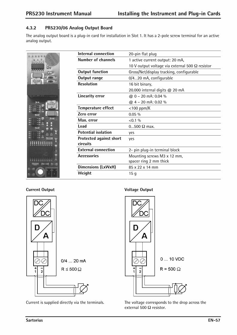
PR5230 Instrument Manual Installing the Instrument and Plug-in Cards
Sartorius EN-57
4.3.2 PR5230/06 Analog Output Board
The analog output board is a plug-in card for installation in Slot 1. It has a 2-pole screw terminal for an active analog output.
Internal connection 20-pin flat plug Number of channels 1 active current output: 20 mA,
10 V output voltage via external 500 ¥ resistor Output function Gross/Net/display tracking, configurable Output range 0/4…20 mA, configurable Resolution 16 bit binary,
20.000 internal digits @ 20 mA Linearity error @ 0 – 20 mA: 0.04 %
@ 4 – 20 mA: 0.02 % Temperature effect <100 ppm/K Zero error 0.05 % Max. error <0.1 % Load 0…500 ¥ max. Potential isolation yes Protected against short circuits
yes
External connection 2- pin plug-in terminal block Accessories Mounting screws M3 x 12 mm,
spacer ring 2 mm thick Dimensions (LxWxH) 85 x 22 x 14 mm
Weight 15 g
Current Output Voltage Output
Current is supplied directly via the terminals. The voltage corresponds to the drop across the external 500 ¥ resistor.
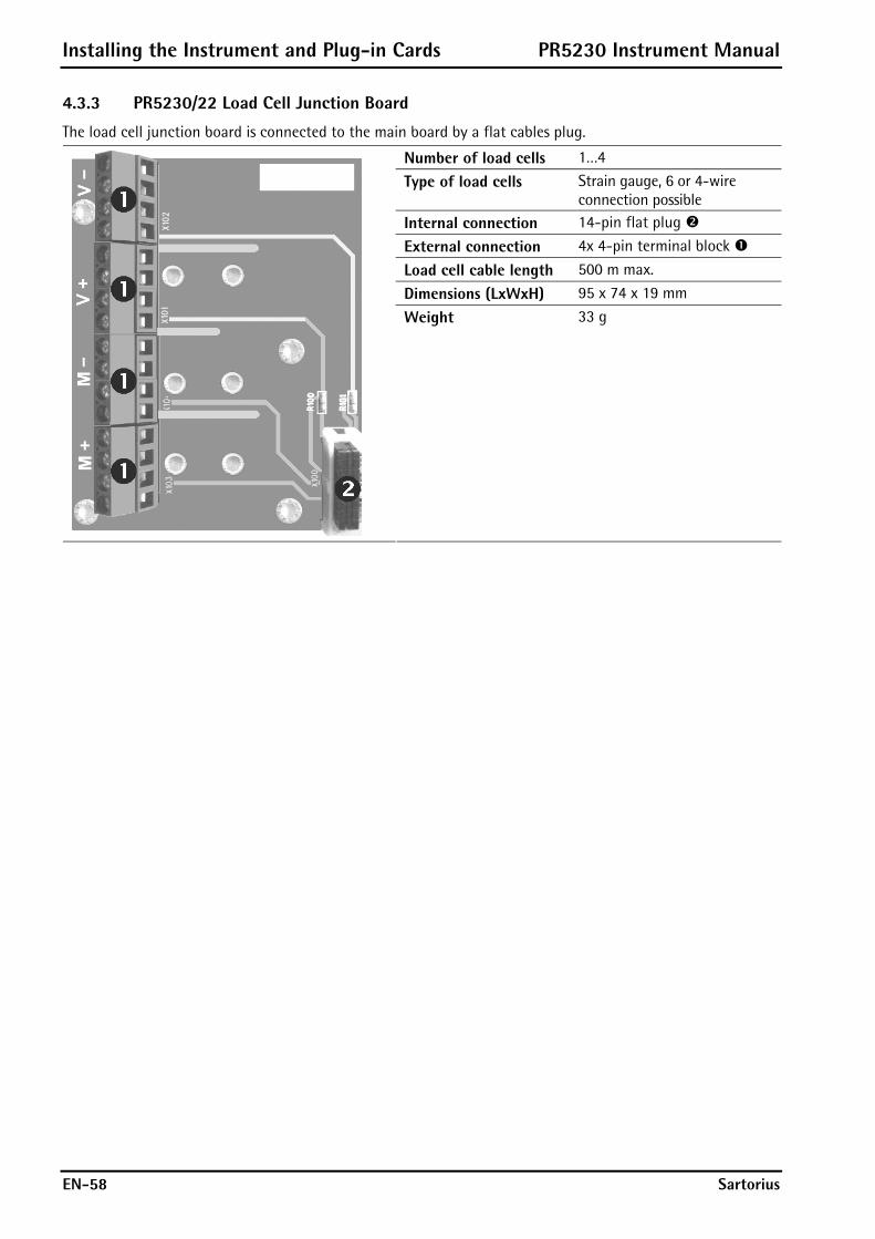
Installing the Instrument and Plug-in Cards PR5230 Instrument Manual
EN-58 Sartorius
4.3.3 PR5230/22 Load Cell Junction Board
The load cell junction board is connected to the main board by a flat cables plug.
Number of load cells 1…4
Type of load cells Strain gauge, 6 or 4-wire connection possible
Internal connection 14-pin flat plug
External connection 4x 4-pin terminal block
Load cell cable length 500 m max.
Dimensions (LxWxH) 95 x 74 x 19 mm
Weight 33 g

PR5230 Instrument Manual Installing the Instrument and Plug-in Cards
Sartorius EN-59
4.3.4 PR1721/41 ProfiBus-DP Interface
The ProfiBus interface PR1721/41 is a plug-in card for mounting in slot 2; see Chapter 4.3.1. Communication protocols and syntax comply with the ProfiBus-DP standard to IEC 61158, with transfer rates up to 12 Mbit/s.
Internal connection 34- pin connector on flat cable for slot 2
External connection 6-pin plug-in terminal block VP DGND A B free free
A = cable color: green B = cable color: red Transfer rate 9.6 kbit/s to 12 Mbit/s,
baud rate auto-detection Connection mode ProfiBus network,
connections can be made/released without affecting other stations
Protocol PROFIBUS-DP-V0 slave to EN 50 170 (DIN 19245), mono or multi-master systems are supported. Master and slave devices, max. 126 nodes possible. Watchdog timer
Addressing Via software, rotary switch on position 0
Configuration GSD file (PR1721/41-specific)
Bus termination Via DIL-switch
Cable Special ProfiBus color: violet, shielded twisted pair cable
Cable impedance 150 ¥
Certificates ProfiBus test center Comdec in Germany and PNO (ProfiBus User Organization). Suitable for industrial applications to CE, UL and cUL
Dimensions (LxWxH) 87 x 55 x 15 mm Potential isolation Optocoupler in lines A and B (RS-485)
Weight 35 g Cable length Max. distance 200 m can be extended with 1.5 Mbit/s by means of additional repeater.
Caution! The terminating resistors can be switched on and off by pressing switch . Make sure the two rotary switches are set to position 0.
Note: The GSD file is stored on the CD (directory ‘Fieldbus’ of the according instrument) supplied with the unit. The current file is also available for download via the Internet: http://www.sartorius-mechatronics.com [Downloads].
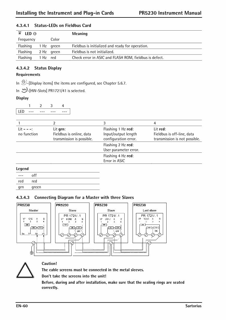
Installing the Instrument and Plug-in Cards PR5230 Instrument Manual
EN-60 Sartorius
4.3.4.1 Status-LEDs on Fieldbus Card
LED Meaning Frequency Color
Flashing 1 Hz green Fieldbus is initialized and ready for operation. Flashing 2 Hz green Fieldbus is not initialized. Flashing 1 Hz red Check error in ASIC and FLASH ROM, fieldbus is defect.
4.3.4.2 Status Display Requirements
In -[Display items] the items are configured, see Chapter 5.6.7.
In -[HW-Slots] PR1721/41 is selected.
Display
1 2 3 4 LED --- --- --- ---
1 2 3 4 Lit - - -: no function
Lit grn: Fieldbus is online, data transmission is possible.
Flashing 1 Hz red: Input/output length configuration error.
Lit red: Fieldbus is off-line, data transmission is not possible.
Flashing 2 Hz red: User parameter error.
Flashing 4 Hz red: Error in ASIC
Legend
--- off red red grn green
4.3.4.3 Connecting Diagram for a Master with three Slaves
Caution! The cable screens must be connected in the metal sleeves. Don’t take the screens into the unit! Before, during and after installation, make sure that the sealing rings are seated correctly.

PR5230 Instrument Manual Installing the Instrument and Plug-in Cards
Sartorius EN-61
4.3.5 PR1721/42 InterBus-S Interface
The InterBus-S interface PR1721/42 is a plug-in card for mounting in slot 2, see Chapter 4.3.1. The interface is based on the InterBus chip technology and enables transfer rates of 500 kbit/s and 2 Mbit/s.
Internal connection 34- pin connector on flat cable for slot 2
External connection 6-pin (IN) and 7-pin (OUT) plug-in terminal block.
D01 D01 DI1 DI1 GND S D02 D02 DI2 DI2 GND C S
C = Con_Test S = Screen Transfer rate 500 kbit/s Topology Bus as a closed ring
Protocol InterBus-S master-slave fixed telegram length, deterministic cyclical process data transmission with max. 10 words I/O.
Cable InterBus, color: green 3x 2 twisted pairs, common shield
Lead termination Not required, due to active ring topology
Cable impedance 150 ¥ Certificates From INTERBUS Club e. V.: Compatibility with InterBus standard. IEC 61158 (Parts 3 to 6) EN 50254 (DIN 19258) Suitable for industrial applications CE, UL & cUL
Dimensions (LxWxH)
87 x 55 x 15 mm Potential isolation Yes, optocoupler and DC/DC converter
Weight 35 g Cable length 400 m (between two remote bus sharing units). Overall length: 13 km
Caution! With Bus OUT 11 and 12 must be bridged, if another slave follows. Thus the link is not fitted at the last slave, see connecting diagram.

Installing the Instrument and Plug-in Cards PR5230 Instrument Manual
EN-62 Sartorius
4.3.5.1 Status-LEDs on Fieldbus Card
LED Meaning Frequency Color
Flashing 1 Hz green Fieldbus is initialized and ready for operation. Flashing 2 Hz green Fieldbus is not initialized. Flashing 1 Hz red Check error in ASIC and FLASH ROM, fieldbus is defect.
4.3.5.2 Status Display Requirements
In -[Display items] the items are configured, see Chapter 5.6.7.
In -[HW-Slots] PR1721/42 is selected.
Display
1 2 3 4 LED --- --- --- ---
1 2 3 4 Lit grn: Cable OK, no Reset mode in the master.
Lit grn: Bus is aktive.
Lit red: Remote bus is not active.
Lit grn: PCP communication is active, hold = 500 ms
Legend
--- off red red grn green
4.3.5.3 Connecting Diagram for a Master with three Slaves
Caution! The cable screens must be taken into the instrument through the cable glands and connected to terminals 6 or 13 (see connecting diagram). Before, during and after installation, make sure that the sealing rings are seated correctly.
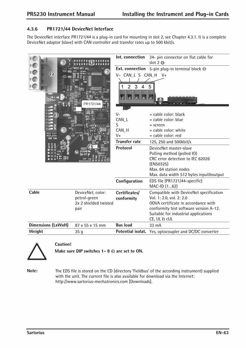
PR5230 Instrument Manual Installing the Instrument and Plug-in Cards
Sartorius EN-63
4.3.6 PR1721/44 DeviceNet Interface
The DeviceNet interface PR1721/44 is a plug-in card for mounting in slot 2, see Chapter 4.3.1. It is a complete DeviceNet adaptor (slave) with CAN controller and transfer rates up to 500 kbit/s.
Int. connection 34- pin connector on flat cable for slot 2
Ext. connection 5-pin plug-in terminal block V– CAN_L S CAN_H V+
V- CAN_L S CAN_H V+
= cable color: black = cable color: blue = screen = cable color: white = cable color: red
Transfer rate 125, 250 and 500kbit/s Protocol DeviceNet master-slave
Polling method (polled IO) CRC error detection to IEC 62026 (EN50325) Max. 64 station nodes Max. data width 512 bytes input&output
Configuration EDS file (PR1721/44-specific) MAC-ID (1…62)
Cable DeviceNet, color: petrol-green 2x 2 shielded twisted pair
Certificates/ conformity
Compatible with DeviceNet specification Vol. 1: 2.0, vol. 2: 2.0 ODVA certificate in accordance with conformity test software version A-12. Suitable for industrial applications CE, UL & cUL
Dimensions (LxWxH) 87 x 55 x 15 mm Bus load 33 mA Weight 35 g Potential isolat. Yes, optocoupler and DC/DC converter
Caution! Make sure DIP switches 1- 8 are set to ON.
Note: The EDS file is stored on the CD (directory ‘Fieldbus’ of the according instrument) supplied with the unit. The current file is also available for download via the Internet: http://www.sartorius-mechatronics.com [Downloads].
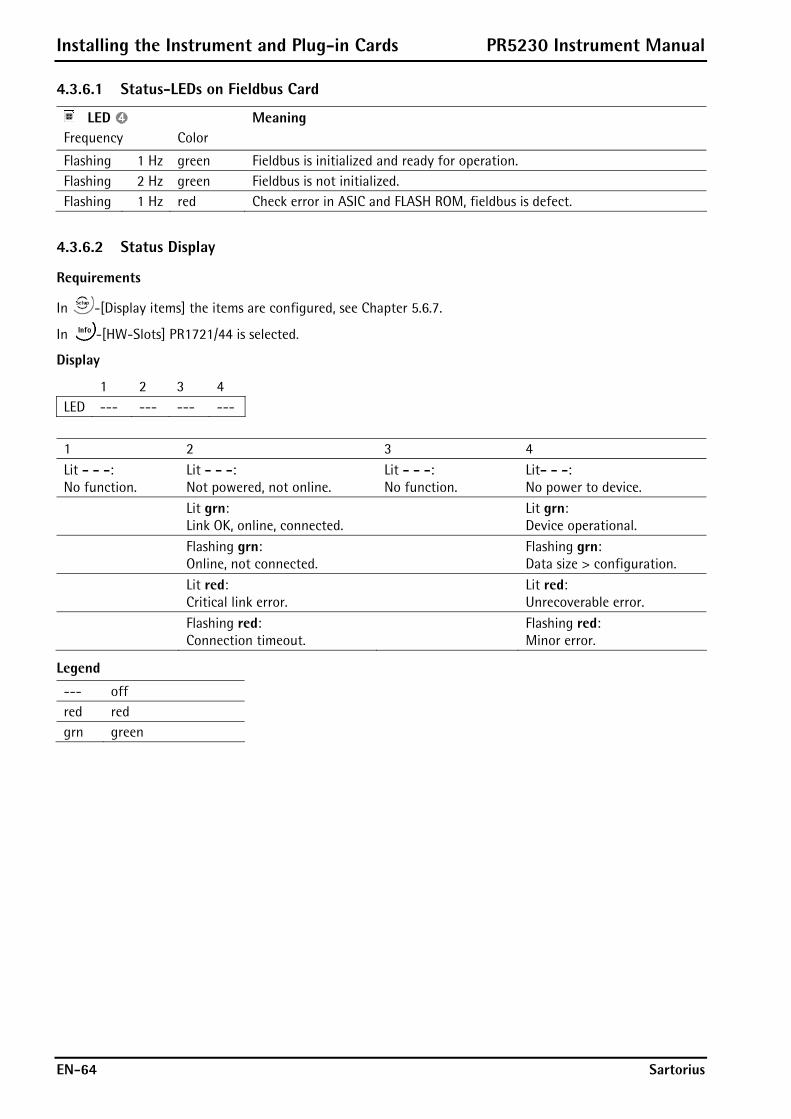
Installing the Instrument and Plug-in Cards PR5230 Instrument Manual
EN-64 Sartorius
4.3.6.1 Status-LEDs on Fieldbus Card
LED Meaning Frequency Color
Flashing 1 Hz green Fieldbus is initialized and ready for operation. Flashing 2 Hz green Fieldbus is not initialized. Flashing 1 Hz red Check error in ASIC and FLASH ROM, fieldbus is defect.
4.3.6.2 Status Display
Requirements
In -[Display items] the items are configured, see Chapter 5.6.7.
In -[HW-Slots] PR1721/44 is selected.
Display
1 2 3 4 LED --- --- --- ---
1 2 3 4 Lit - - -: No function.
Lit - - -: Not powered, not online.
Lit - - -: No function.
Lit- - -: No power to device.
Lit grn: Link OK, online, connected.
Lit grn: Device operational.
Flashing grn: Online, not connected.
Flashing grn: Data size > configuration.
Lit red: Critical link error.
Lit red: Unrecoverable error.
Flashing red: Connection timeout.
Flashing red: Minor error.
Legend
--- off red red grn green
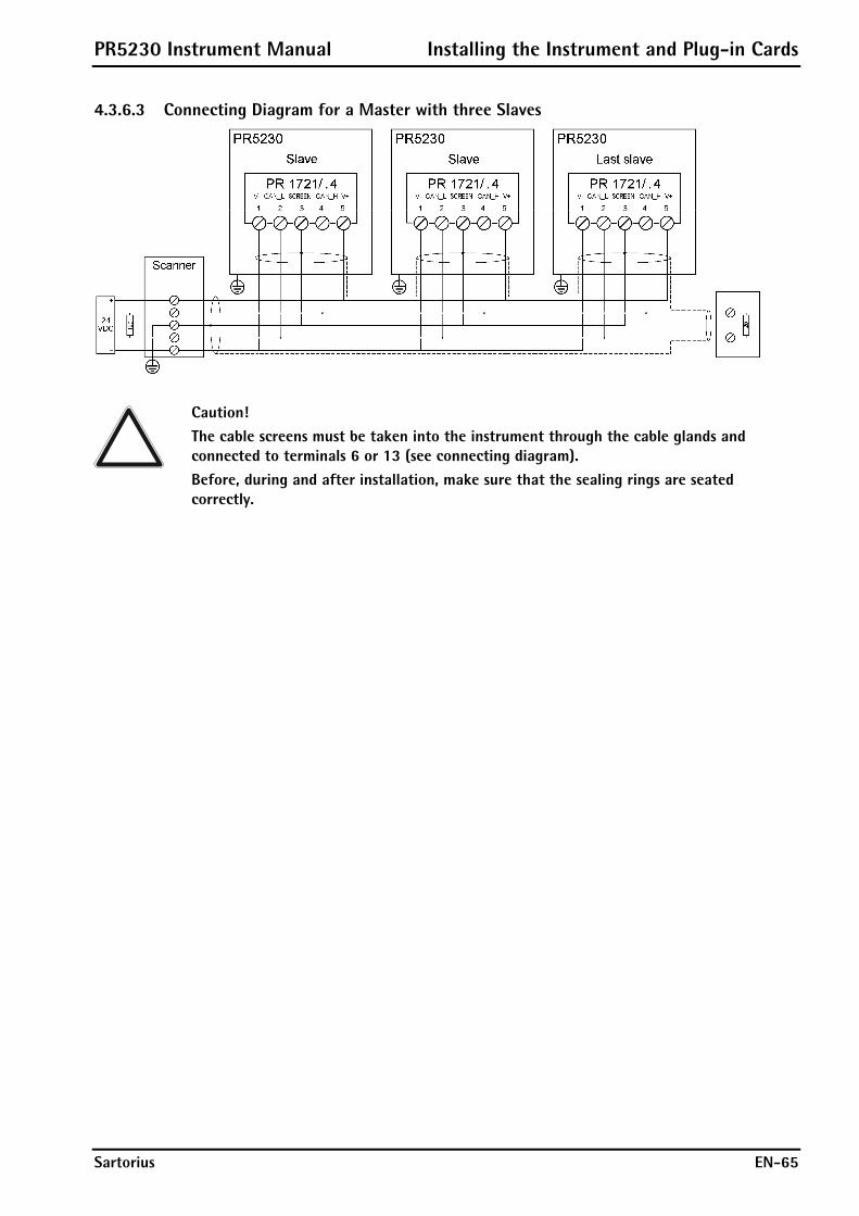
PR5230 Instrument Manual Installing the Instrument and Plug-in Cards
Sartorius EN-65
4.3.6.3 Connecting Diagram for a Master with three Slaves
Caution! The cable screens must be taken into the instrument through the cable glands and connected to terminals 6 or 13 (see connecting diagram). Before, during and after installation, make sure that the sealing rings are seated correctly.

Installing the Instrument and Plug-in Cards PR5230 Instrument Manual
EN-66 Sartorius
4.3.7 PR1721/45 CC-Link Interface
The CC-Link interface PR1721/45 is a plug-in card for mounting in slot 2, see Chapter 4.3.1. It contains all functions to provide a complete CC-Link slave with transfer rates up to 10 Mbps.
Internal connection 34- pin connector on flat cable for slot 2
External connection 5-pin plug-in terminal block DA DB GND S PE
S = screen Transfer rate 156; 625 kbps; 2,5; 5, 10 Mbps Protocol CRC error detection, 128 I/O bits and
16 (32 bit) words, max. 64 station nodesCable 2x 2 shielded twisted pair Bus termination 110 ¥ at the cable ends Bus load 100 mA Configuration CSP file (PR1721/45-specific)
Certificates/ conformity
Type: ABS-CCL (H/W: 1.01, S/W: 2.00.05, CC-Link: 2.0)
Reference Number 372 Dimensions (LxWxH) 87 x 55 x 15 mm Potential isolation Yes, optocoupler and DC/DC converter Weight 125 g Cable length 100m @ 10 Mbps, 1200m @ 156 kbps
Caution! Ensure that the three rotary switches (station no. and baud rate) are set to 9. Settings are made via software.
Note: The CSP file is stored on the CD (directory ‘Fieldbus’ of the according instrument) supplied with the unit. The current file is also available for download via the Internet: http://www.sartorius-mechatronics.com [Downloads].

PR5230 Instrument Manual Installing the Instrument and Plug-in Cards
Sartorius EN-67
4.3.7.1 Status LEDs on Fieldbus Card
LED Meaning Frequency Color
Flashing 1 Hz green Fieldbus is initialized and ready for operation. Flashing 2 Hz green Fieldbus is not initialized. Flashing 1 Hz red Check error in ASIC and FLASH ROM, fieldbus is defect.
4.3.7.2 Status Display
Requirements
In -[Display items] the items are configured, see Chapter 5.6.7.
In -[HW-Slots] PR1721/45 is selected.
Display
1 2 3 4 LED --- --- --- ---
1 2 3 4 Lit - - -: No power on the module.
Lit - - -: No power on the module.
Lit - - -: No power on the module.
Lit - - -: No power on the module.
Lit grn: Normal operation.
Lit red: CRC error, Illegal station number or illegal baudrate selected.
Lit grn: Data being transmitted.
Lit grn: Data being received.
Legend
--- off red red grn green
4.3.7.3 Connection
Caution! The cable screen must be taken into the instrument through the cable gland and connected to terminal 4 (see page 66). Before, during and after installation, make sure that the sealing rings are seated correctly.
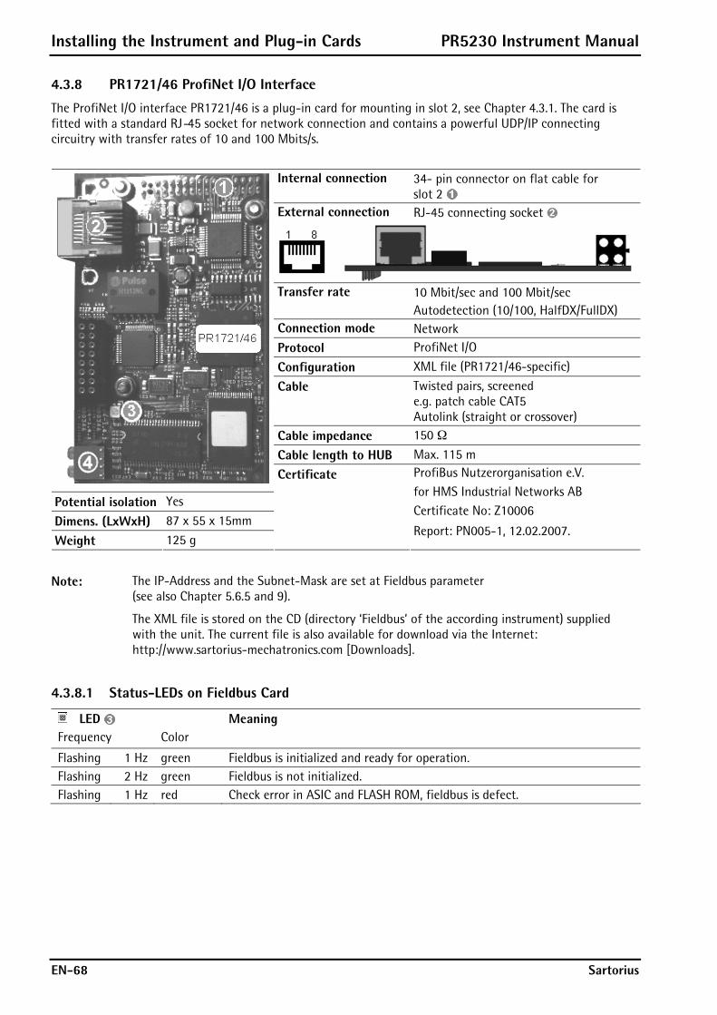
Installing the Instrument and Plug-in Cards PR5230 Instrument Manual
EN-68 Sartorius
4.3.8 PR1721/46 ProfiNet I/O Interface
The ProfiNet I/O interface PR1721/46 is a plug-in card for mounting in slot 2, see Chapter 4.3.1. The card is fitted with a standard RJ-45 socket for network connection and contains a powerful UDP/IP connecting circuitry with transfer rates of 10 and 100 Mbits/s.
Internal connection 34- pin connector on flat cable for slot 2
External connection RJ-45 connecting socket
Transfer rate 10 Mbit/sec and 100 Mbit/sec
Autodetection (10/100, HalfDX/FullDX) Connection mode Network Protocol ProfiNet I/O
Configuration XML file (PR1721/46-specific)
Cable Twisted pairs, screened e.g. patch cable CAT5 Autolink (straight or crossover)
Cable impedance 150 ¥
Cable length to HUB Max. 115 m
Potential isolation Yes
Dimens. (LxWxH) 87 x 55 x 15mm
Weight 125 g
Certificate ProfiBus Nutzerorganisation e.V. for HMS Industrial Networks AB Certificate No: Z10006
Report: PN005-1, 12.02.2007.
Note: The IP-Address and the Subnet-Mask are set at Fieldbus parameter (see also Chapter 5.6.5 and 9).
The XML file is stored on the CD (directory ‘Fieldbus’ of the according instrument) supplied with the unit. The current file is also available for download via the Internet: http://www.sartorius-mechatronics.com [Downloads].
4.3.8.1 Status-LEDs on Fieldbus Card
LED Meaning Frequency Color
Flashing 1 Hz green Fieldbus is initialized and ready for operation. Flashing 2 Hz green Fieldbus is not initialized. Flashing 1 Hz red Check error in ASIC and FLASH ROM, fieldbus is defect.

PR5230 Instrument Manual Installing the Instrument and Plug-in Cards
Sartorius EN-69
4.3.8.2 Status Display
Requirements
In -[Display items] the items are configured, see Chapter 5.6.7.
In -[HW-Slots] PR1721/46 is selected.
Display
1 2 3 4 LED --- --- --- ---
LEDs on the fielbus card 1 2
3 4
LED 1 LED 2 LED 3 LED 4 Lit - - -: No link or power off.
Lit - - -: Offline, no connection.
Lit - - -: No function.
Lit - - -: No power or not initialized.
Lit grn: Link established.
Lit grn: Link established and online connected.
Lit grn: Initialized, no error.
Flashing 1 Hz grn: Receiving/Transmitting data.
Flashing 1 Hz grn: Online, no connection.
Flashing 1 Hz grn: Diagnostic data available.
Flashing 2 Hz grn: Engineering tool to identify is active.
Flashing 1 Hz red: Configuration error.
Flashing 3 Hz red: No station name, no IP address
Flashing 4 Hz red: Internal error.
Legend
--- off red red grn green
4.3.8.3 Connection
Take the cable (e.g. patch cable CAT5) into the instrument through the metal sleeve of the cable gland, strip the insulation and mount the delivered RJ-45 plug (see mounting informations).
Put the RJ-45 plug into the RJ-45 connecting socket of the fieldbus card.
Tighten the cable gland of the instrument.
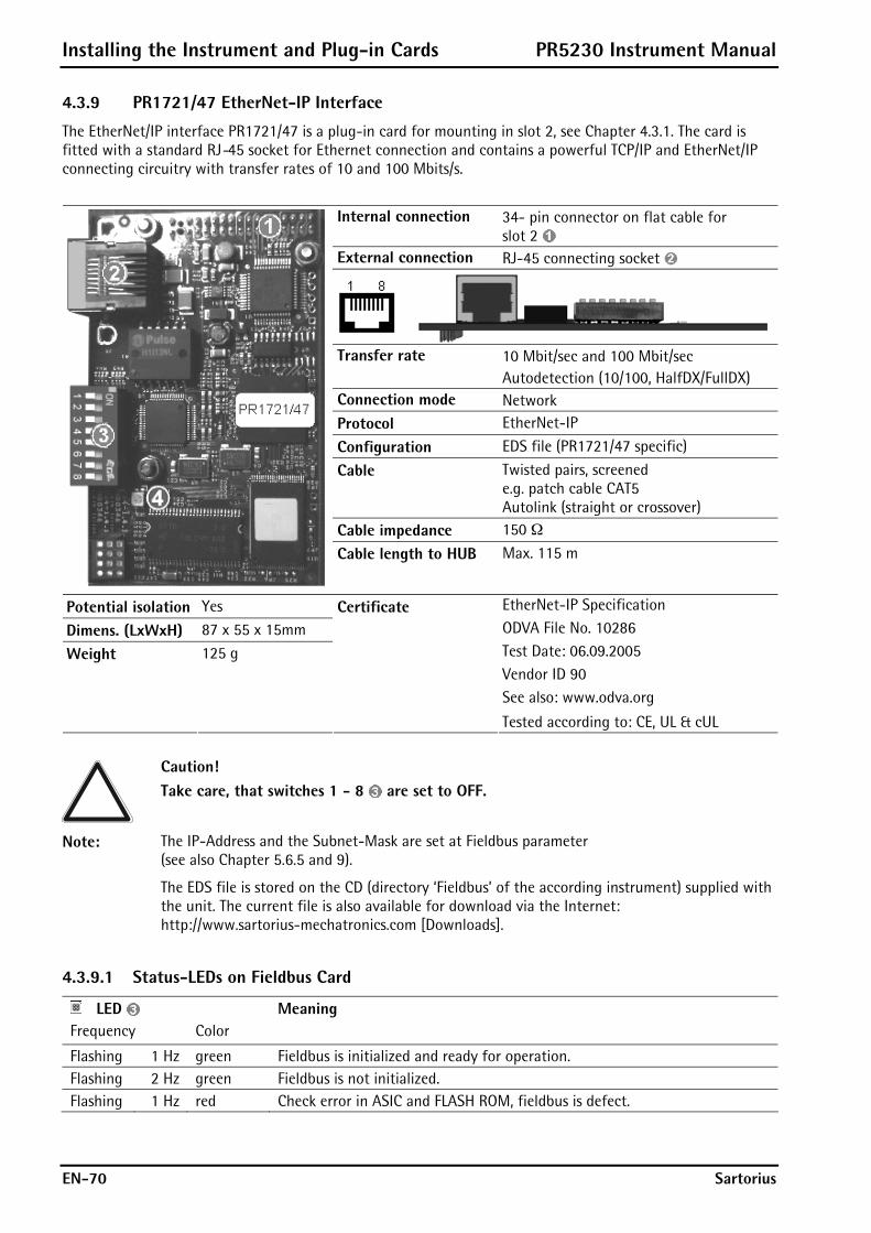
Installing the Instrument and Plug-in Cards PR5230 Instrument Manual
EN-70 Sartorius
4.3.9 PR1721/47 EtherNet-IP Interface
The EtherNet/IP interface PR1721/47 is a plug-in card for mounting in slot 2, see Chapter 4.3.1. The card is fitted with a standard RJ-45 socket for Ethernet connection and contains a powerful TCP/IP and EtherNet/IP connecting circuitry with transfer rates of 10 and 100 Mbits/s.
Internal connection 34- pin connector on flat cable for slot 2
External connection RJ-45 connecting socket
Transfer rate 10 Mbit/sec and 100 Mbit/sec Autodetection (10/100, HalfDX/FullDX)
Connection mode Network Protocol EtherNet-IP
Configuration EDS file (PR1721/47 specific)
Cable Twisted pairs, screened e.g. patch cable CAT5 Autolink (straight or crossover)
Cable impedance 150 ¥
Cable length to HUB Max. 115 m
Potential isolation Yes
Dimens. (LxWxH) 87 x 55 x 15mm
Weight 125 g
Certificate EtherNet-IP Specification ODVA File No. 10286 Test Date: 06.09.2005 Vendor ID 90 See also: www.odva.org
Tested according to: CE, UL & cUL
Caution! Take care, that switches 1 - 8 are set to OFF.
Note: The IP-Address and the Subnet-Mask are set at Fieldbus parameter (see also Chapter 5.6.5 and 9).
The EDS file is stored on the CD (directory ‘Fieldbus’ of the according instrument) supplied with the unit. The current file is also available for download via the Internet: http://www.sartorius-mechatronics.com [Downloads].
4.3.9.1 Status-LEDs on Fieldbus Card
LED Meaning Frequency Color
Flashing 1 Hz green Fieldbus is initialized and ready for operation. Flashing 2 Hz green Fieldbus is not initialized. Flashing 1 Hz red Check error in ASIC and FLASH ROM, fieldbus is defect.
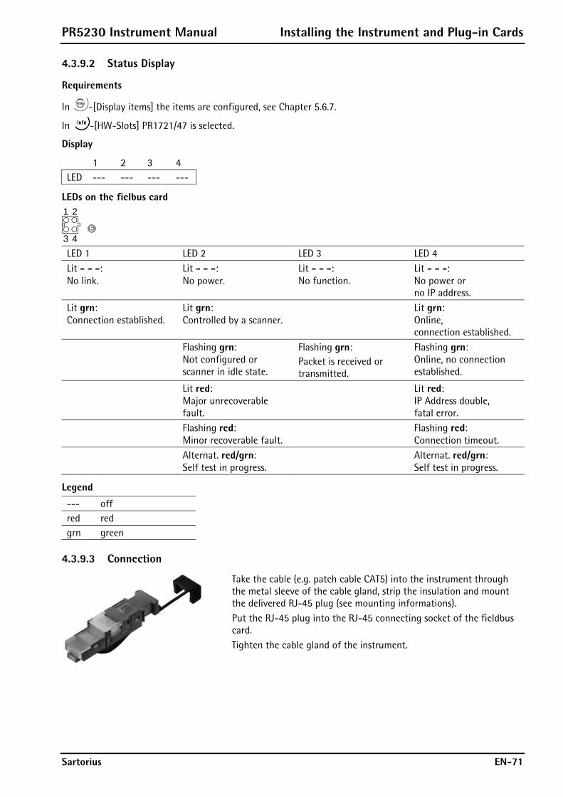
PR5230 Instrument Manual Installing the Instrument and Plug-in Cards
Sartorius EN-71
4.3.9.2 Status Display
Requirements
In -[Display items] the items are configured, see Chapter 5.6.7.
In -[HW-Slots] PR1721/47 is selected.
Display
1 2 3 4 LED --- --- --- ---
LEDs on the fielbus card 1 2
3 4
LED 1 LED 2 LED 3 LED 4 Lit - - -: No link.
Lit - - -: No power.
Lit - - -: No function.
Lit - - -: No power or no IP address.
Lit grn: Connection established.
Lit grn: Controlled by a scanner.
Lit grn: Online, connection established.
Flashing grn: Not configured or scanner in idle state.
Flashing grn: Packet is received or transmitted.
Flashing grn: Online, no connection established.
Lit red: Major unrecoverable fault.
Lit red: IP Address double, fatal error.
Flashing red: Minor recoverable fault.
Flashing red: Connection timeout.
Alternat. red/grn: Self test in progress.
Alternat. red/grn: Self test in progress.
Legend
--- off red red grn green
4.3.9.3 Connection
Take the cable (e.g. patch cable CAT5) into the instrument through the metal sleeve of the cable gland, strip the insulation and mount the delivered RJ-45 plug (see mounting informations).
Put the RJ-45 plug into the RJ-45 connecting socket of the fieldbus card.
Tighten the cable gland of the instrument.
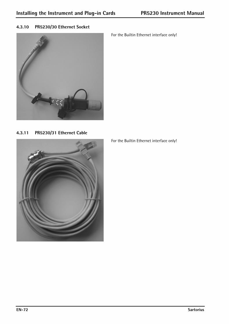
Installing the Instrument and Plug-in Cards PR5230 Instrument Manual
EN-72 Sartorius
4.3.10 PR5230/30 Ethernet Socket
For the Builtin Ethernet interface only!
4.3.11 PR5230/31 Ethernet Cable
For the Builtin Ethernet interface only!

PR5230 Instrument Manual Installing the Instrument and Plug-in Cards
Sartorius EN-73
4.4 Connecting Load Cells Load cells or analog platforms (e.g. from the CAPP series) can be connected. The supply voltage is protected from short circuit and overload.
Caution! Do not shorten the load cell cable. Connect the prepared cable end and roll up the remaining cable.
Terminal block Connection Description + M + Meas. + Meas. voltage/load cell output - M - Meas. - Meas. voltage/load cell output + V + Supply + Supply voltage + S + Sense + Sense - S - Sense - Sense - V - Supply - Supply voltage
Ground Ground
4.4.1 Connecting a Load Cell with 4-Wire Cable
Caution! The cable colors shown above are applicable to the 4-wire PR62.. series load cells. Before connecting, check the assignment of cable colors in the load cell manual.
Provide links: between – Supply (-V) and – Sense (-S) between + Supply (+V) and + Sense (+S)
4.4.2 Connecting PR6221 Load Cells
See installation manuals of PR6221 and PR6021/08, -/68.
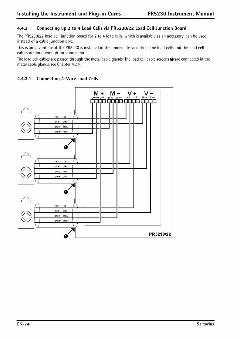
Installing the Instrument and Plug-in Cards PR5230 Instrument Manual
EN-74 Sartorius
4.4.3 Connecting up 2 to 4 Load Cells via PR5230/22 Load Cell Junction Board
The PR5230/22 load cell junction board for 2 to 4 load cells, which is available as an accessory, can be used instead of a cable junction box. This is an advantage, if the PR5230 is installed in the immediate vicinity of the load cells and the load cell cables are long enough for connection. The load cell cables are passed through the metal cable glands. The load cell cable screens are connected in the metal cable glands, see Chapter 4.2.4.
4.4.3.1 Connecting 4-Wire Load Cells
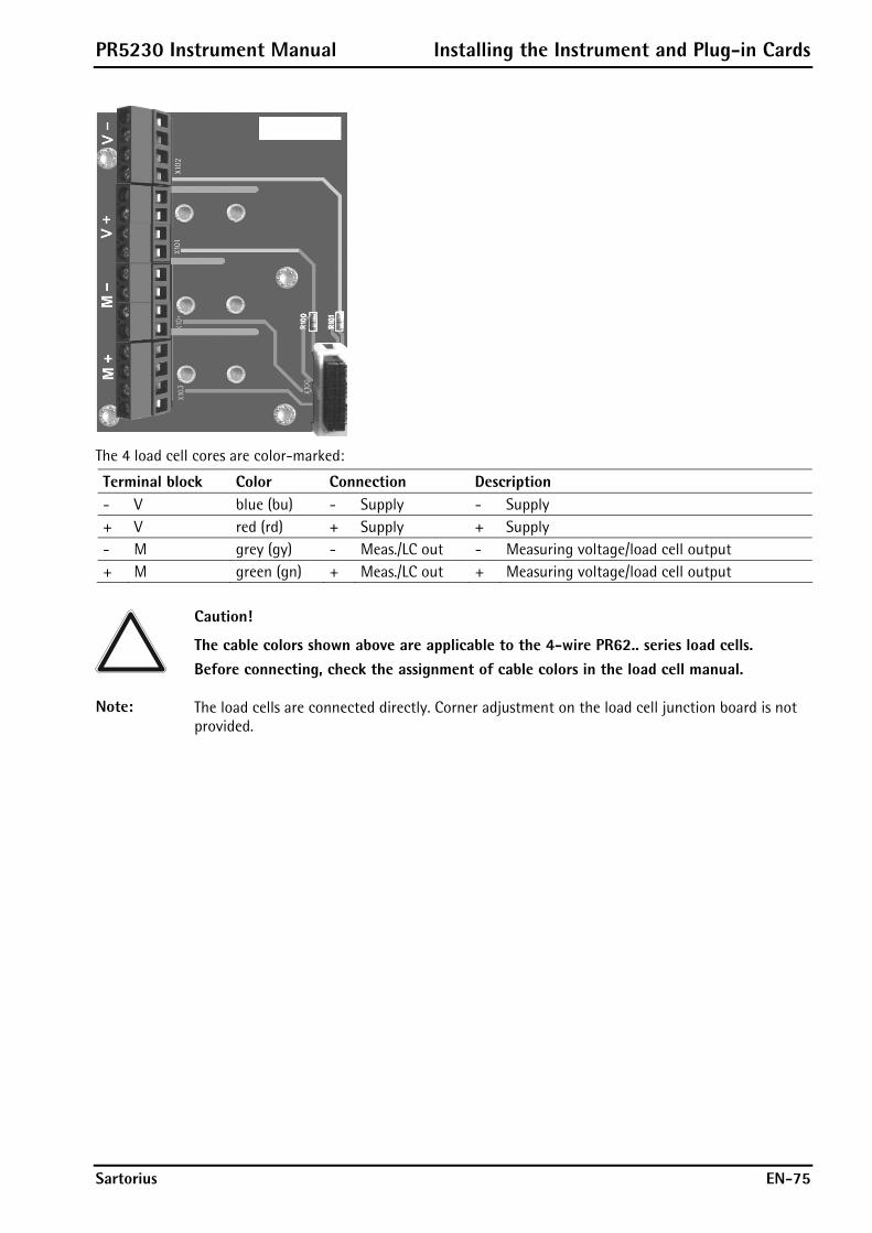
PR5230 Instrument Manual Installing the Instrument and Plug-in Cards
Sartorius EN-75
The 4 load cell cores are color-marked:
Terminal block Color Connection Description - V blue (bu) - Supply - Supply + V red (rd) + Supply + Supply - M grey (gy) - Meas./LC out - Measuring voltage/load cell output + M green (gn) + Meas./LC out + Measuring voltage/load cell output
Caution!
The cable colors shown above are applicable to the 4-wire PR62.. series load cells. Before connecting, check the assignment of cable colors in the load cell manual.
Note: The load cells are connected directly. Corner adjustment on the load cell junction board is not provided.

Installing the Instrument and Plug-in Cards PR5230 Instrument Manual
EN-76 Sartorius
4.4.3.2 Connecting 6-Wire Load Cells
PR5230/22
red rotwhite weiß
black schwarzblue blau
grey graugreen grün
V –V +M –M +
red rotwhite weiß
black schwarzblue blau
grey graugreen grün
red rotwhite weiß
black schwarzblue blau
grey graugreen grün
green grün grey grau red rot blue blau
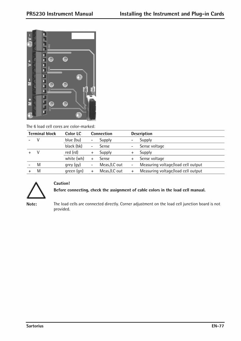
PR5230 Instrument Manual Installing the Instrument and Plug-in Cards
Sartorius EN-77
The 6 load cell cores are color-marked:
Terminal block Color LC Connection Description - V blue (bu) - Supply - Supply black (bk) - Sense - Sense voltage + V red (rd) + Supply + Supply white (wh) + Sense + Sense voltage - M grey (gy) - Meas./LC out - Measuring voltage/load cell output + M green (gn) + Meas./LC out + Measuring voltage/load cell output
Caution! Before connecting, check the assignment of cable colors in the load cell manual.
Note: The load cells are connected directly. Corner adjustment on the load cell junction board is not provided.
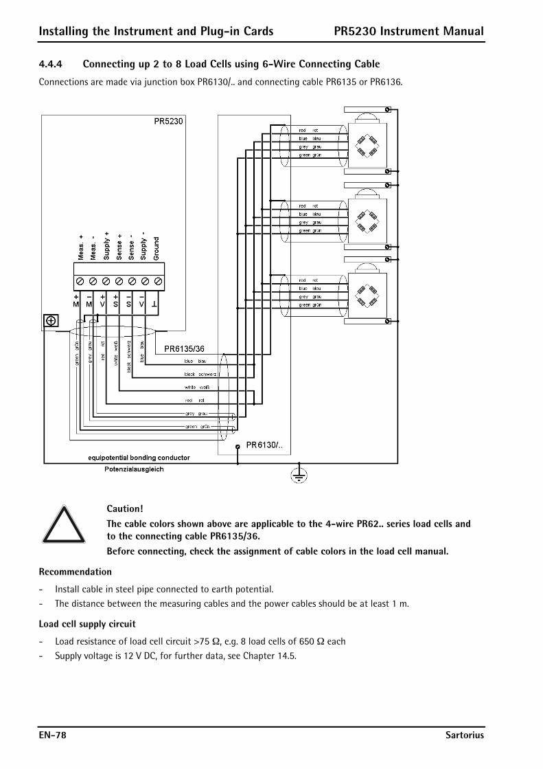
Installing the Instrument and Plug-in Cards PR5230 Instrument Manual
EN-78 Sartorius
4.4.4 Connecting up 2 to 8 Load Cells using 6-Wire Connecting Cable
Connections are made via junction box PR6130/.. and connecting cable PR6135 or PR6136.
Caution! The cable colors shown above are applicable to the 4-wire PR62.. series load cells and to the connecting cable PR6135/36. Before connecting, check the assignment of cable colors in the load cell manual.
Recommendation
- Install cable in steel pipe connected to earth potential. - The distance between the measuring cables and the power cables should be at least 1 m.
Load cell supply circuit
- Load resistance of load cell circuit >75 ¥, e.g. 8 load cells of 650 ¥ each - Supply voltage is 12 V DC, for further data, see Chapter 14.5.

PR5230 Instrument Manual Installing the Instrument and Plug-in Cards
Sartorius EN-79
4.4.5 Connecting Load Cells with External Supply
When the load of the load cells is <75 ¥ (e.g. more than 4 load cells with 350 ¥), external load cell supply is required. In this case, the internal supply is replaced by a potential-free external supply. The neutral wire of the external supply voltage (0 ext. supply) must be connected to the instrument housing to ensure that the voltage is symmetrical to 0. The internal supply is not connected!
Caution! The cable colors shown above are applicable to the connecting cable PR6135/36. Before connecting, check the assignment of cable colors in the load cell manual.
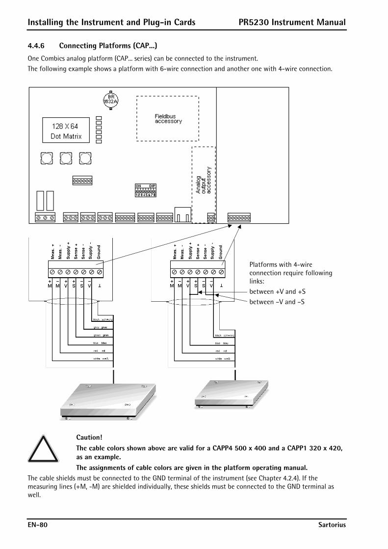
Installing the Instrument and Plug-in Cards PR5230 Instrument Manual
EN-80 Sartorius
4.4.6 Connecting Platforms (CAP...)
One Combics analog platform (CAP... series) can be connected to the instrument. The following example shows a platform with 6-wire connection and another one with 4-wire connection.
Platforms with 4-wire connection require following links: between +V and +S between –V and –S
Caution! The cable colors shown above are valid for a CAPP4 500 x 400 and a CAPP1 320 x 420, as an example. The assignments of cable colors are given in the platform operating manual.
The cable shields must be connected to the GND terminal of the instrument (see Chapter 4.2.4). If the measuring lines (+M, -M) are shielded individually, these shields must be connected to the GND terminal as well.
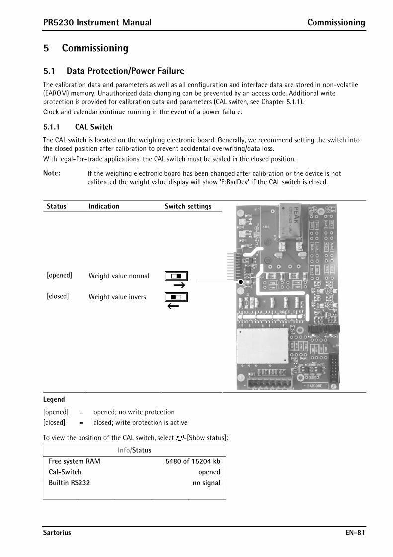
PR5230 Instrument Manual Commissioning
Sartorius EN-81
5 Commissioning
5.1 Data Protection/Power Failure The calibration data and parameters as well as all configuration and interface data are stored in non-volatile (EAROM) memory. Unauthorized data changing can be prevented by an access code. Additional write protection is provided for calibration data and parameters (CAL switch, see Chapter 5.1.1). Clock and calendar continue running in the event of a power failure.
5.1.1 CAL Switch
The CAL switch is located on the weighing electronic board. Generally, we recommend setting the switch into the closed position after calibration to prevent accidental overwriting/data loss. With legal-for-trade applications, the CAL switch must be sealed in the closed position.
Note: If the weighing electronic board has been changed after calibration or the device is not calibrated the weight value display will show ‘E:BadDev’ if the CAL switch is closed.
Status Indication Switch settings
[opened] Weight value normal
[closed] Weight value invers
Legend
[opened] = opened; no write protection [closed] = closed; write protection is active
To view the position of the CAL switch, select -[Show status]:
Info/Status
Free system RAM 5480 of 15204 kb
Cal-Switch opened
Builtin RS232 no signal
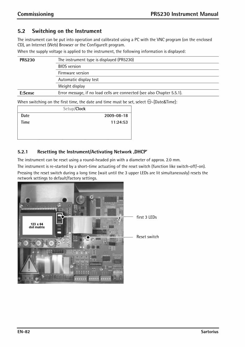
Commissioning PR5230 Instrument Manual
EN-82 Sartorius
5.2 Switching on the Instrument The instrument can be put into operation and calibrated using a PC with the VNC program (on the enclosed CD), an Internet (Web) Browser or the ConfigureIt program. When the supply voltage is applied to the instrument, the following information is displayed:
PR5230 The instrument type is displayed (PR5230)
BIOS version
Firmware version
Automatic display test
Weight display
E:Sense Error message, if no load cells are connected (see also Chapter 5.5.1).
When switching on the first time, the date and time must be set, select -[Date&Time]:
Setup/Clock
Date 2009-08-18
Time 11:24:53
5.2.1 Resetting the Instrument/Activating Network ‚DHCP’
The instrument can be reset using a round-headed pin with a diameter of approx. 2.0 mm. The instrument is re-started by a short-time actuating of the reset switch (function like switch-off/-on). Pressing the reset switch during a long time (wait until the 3 upper LEDs are lit simultaneously) resets the network settings to default/factory settings.
first 3 LEDs Reset switch

PR5230 Instrument Manual Commissioning
Sartorius EN-83
That means: - 'DHCP' is activated.
- ‘Host name’ is initialized e.g. PR5230-8BB499 (instrument type-MAC ID).
Example of MAC ID: 00-aa-00-8b-b4-99
This ensures that a valid address for identification of the instrument in the network can be assigned to the instrument, see Chapter 5.6.6.
Note: The last 3 bytes of the MAC ID are displayed. A label with the complete MAC ID is fitted to the outside of the device. An device set to ’active’ DHCP (default/factory setting) and connected to an IT network (company network) with a DHCP server does not require further actions except for a 2...3-minute waiting time. Subsequently, a network connection is established automatically (device <-> workstation/PC).
Temporarily connected PCs must have the following network adaptor properties (DHCP/DNS automatic):
PR5230 can be operated only, if a PC is connected! For commissioning, the first network contact is possible only by finding the IP address/subnet mask under DHCP ’active’ (factory setting) automatically.
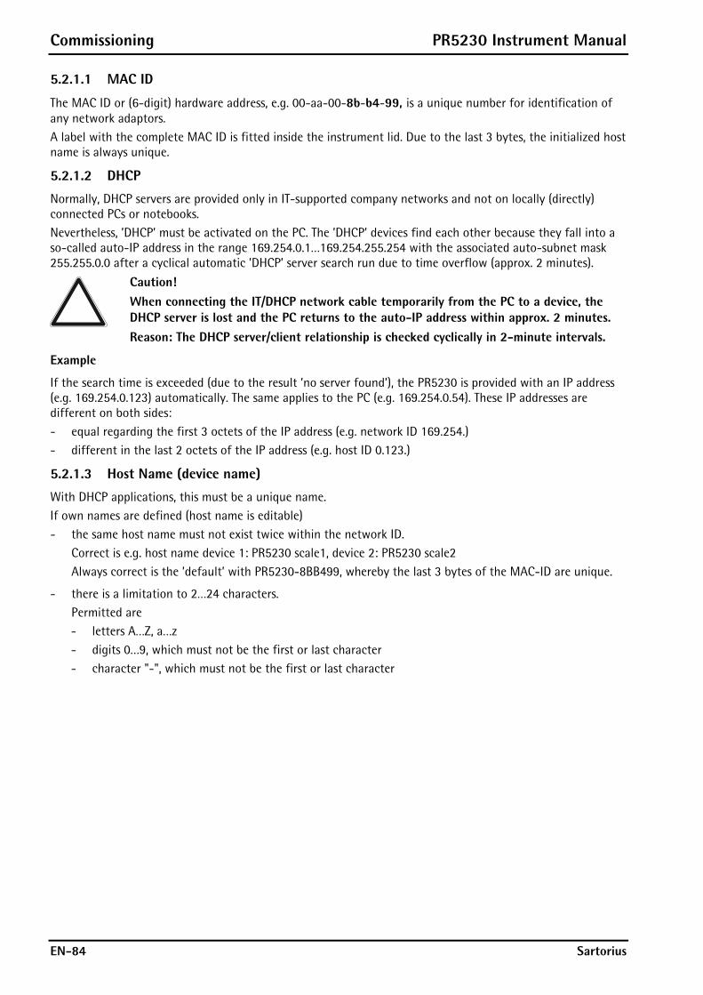
Commissioning PR5230 Instrument Manual
EN-84 Sartorius
5.2.1.1 MAC ID
The MAC ID or (6-digit) hardware address, e.g. 00-aa-00-8b-b4-99, is a unique number for identification of any network adaptors. A label with the complete MAC ID is fitted inside the instrument lid. Due to the last 3 bytes, the initialized host name is always unique.
5.2.1.2 DHCP
Normally, DHCP servers are provided only in IT-supported company networks and not on locally (directly) connected PCs or notebooks. Nevertheless, ’DHCP’ must be activated on the PC. The ’DHCP’ devices find each other because they fall into a so-called auto-IP address in the range 169.254.0.1…169.254.255.254 with the associated auto-subnet mask 255.255.0.0 after a cyclical automatic ’DHCP’ server search run due to time overflow (approx. 2 minutes).
Caution! When connecting the IT/DHCP network cable temporarily from the PC to a device, the DHCP server is lost and the PC returns to the auto-IP address within approx. 2 minutes. Reason: The DHCP server/client relationship is checked cyclically in 2-minute intervals.
Example
If the search time is exceeded (due to the result ’no server found’), the PR5230 is provided with an IP address (e.g. 169.254.0.123) automatically. The same applies to the PC (e.g. 169.254.0.54). These IP addresses are different on both sides: - equal regarding the first 3 octets of the IP address (e.g. network ID 169.254.) - different in the last 2 octets of the IP address (e.g. host ID 0.123.)
5.2.1.3 Host Name (device name)
With DHCP applications, this must be a unique name. If own names are defined (host name is editable) - the same host name must not exist twice within the network ID.
Correct is e.g. host name device 1: PR5230 scale1, device 2: PR5230 scale2 Always correct is the ’default’ with PR5230-8BB499, whereby the last 3 bytes of the MAC-ID are unique.
- there is a limitation to 2…24 characters. Permitted are - letters A…Z, a…z - digits 0…9, which must not be the first or last character - character "-", which must not be the first or last character
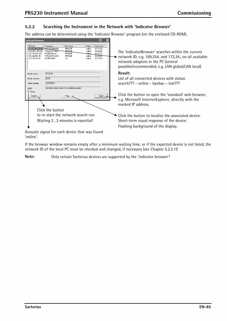
PR5230 Instrument Manual Commissioning
Sartorius EN-85
5.2.2 Searching the Instrument in the Network with 'Indicator Browser'
The address can be determined using the 'Indicator Browser' program (on the enclosed CD-ROM).
The ’IndicatorBrowser’ searches within the current network ID, e.g. 169.254. and 172.24., on all available network adaptors in the PC (several possible/recommended, e.g. LAN global/LAN local)
Result: List of all connected devices with status: search??? – online - byebye – lost??? Click the button to open the ’standard’ web browser, e.g. Microsoft InternetExplorer, directly with the marked IP address.
Click the button to re-start the network search run. Waiting 2…3 minutes is essential!
Acoustic signal for each device that was found ’online’.
Click the button to localize the associated device. Short-term visual response of the device: Flashing background of the display.
If the browser window remains empty after a minimum waiting time, or if the expected device is not listed, the network ID of the local PC must be checked and changed, if necessary (see Chapter 5.2.2.1)!
Note: Only certain Sartorius devices are supported by the ’indicator browser’!

Commissioning PR5230 Instrument Manual
EN-86 Sartorius
5.2.2.1 Checking the Current Network ID on the PC
Windows XP
Click menu item [Run] in the start menu. The following input window appears:
Enter command [cmd] and click [OK] to open the prompt.
Enter command [ipconfig] and press ‘Enter’.
Example with 2 network ports in the PC: - LAN global
’company network’ network ID 172.24. - LAN local
’scale network’ network ID 169.254.
Devices and PC must be located in the same network, i.e. the first two octets of the network ID must correspond. Device 169.254. – PC 169.254. Device 172.24. – PC 172.24. For the last two octets, the range of the subnet mask must be taken into account. The max. range is e.g. 255.255.0.0.

PR5230 Instrument Manual Commissioning
Sartorius EN-87
5.2.2.2 Searching for an unknown IP Address with known Device Type and MAC ID
Prerequisite
The DNS server is available (see also Chapter 5.2.1).
The entry must consist of the following data: - Device type, e.g. PR5230 - Use the last 3 bytes of the MAC ID on the
label in the device, e.g. 00-aa-00-8b-b4-99
Enter the command [ping PR5230-8BB499] and press Enter. The related IP address is displayed, e.g. 172.24.20.131.
5.2.2.3 Checking the physical Connection to the Device with known IP Address
Prerequisite
The DNS server is available (see also Chapter 5.2.1). The IP address is known, e.g. 169.254.104.113.
Enter command [ping 169.254.104.113] and press ‘Enter’. If a connection is available, the connection data are listed. Network quality feature: Time xx msec Help: Enter command [ping/help] and press
‘Enter’.
If no connection is available, a timeout is sent as reply (replies are delayed significantly!).
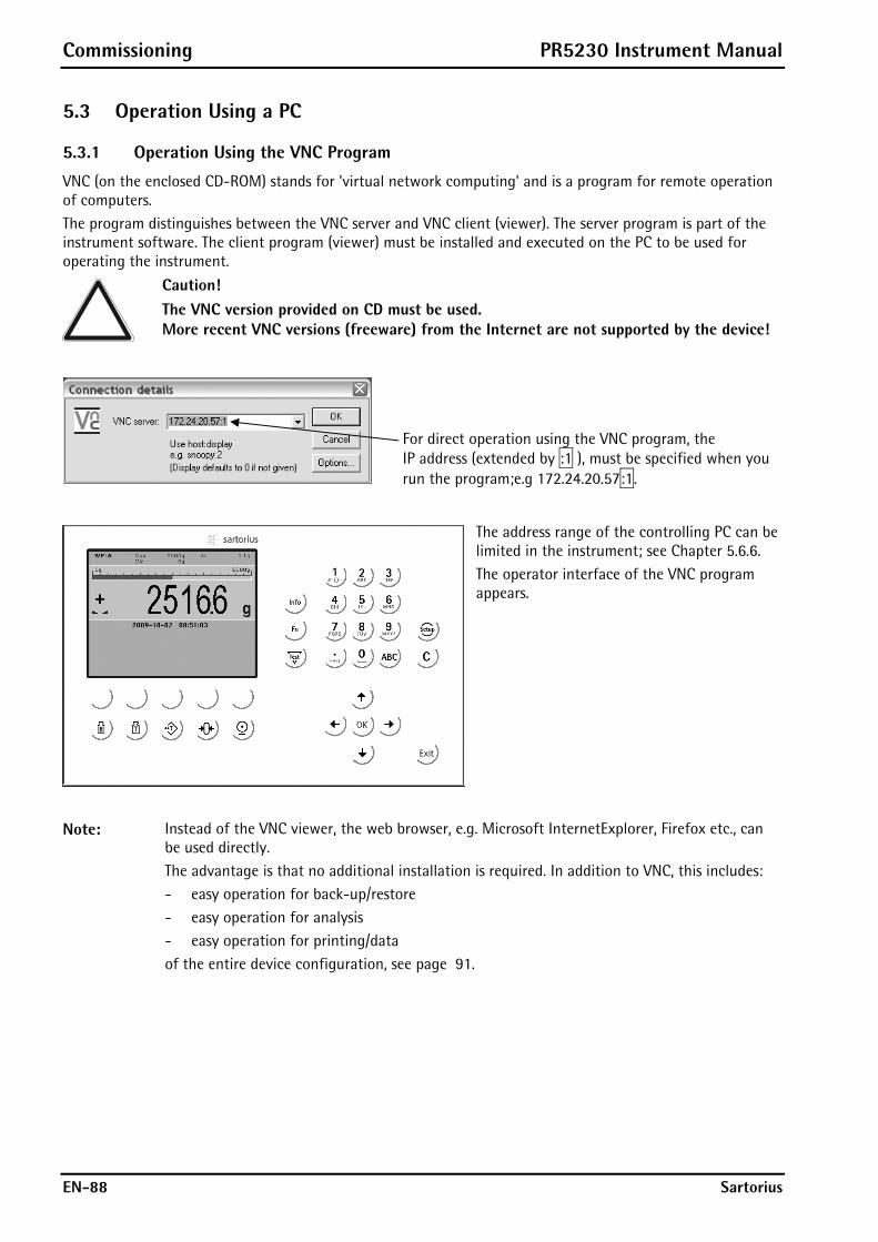
Commissioning PR5230 Instrument Manual
EN-88 Sartorius
5.3 Operation Using a PC
5.3.1 Operation Using the VNC Program
VNC (on the enclosed CD-ROM) stands for 'virtual network computing' and is a program for remote operation of computers. The program distinguishes between the VNC server and VNC client (viewer). The server program is part of the instrument software. The client program (viewer) must be installed and executed on the PC to be used for operating the instrument.
Caution! The VNC version provided on CD must be used. More recent VNC versions (freeware) from the Internet are not supported by the device!
For direct operation using the VNC program, the IP address (extended by :1 ), must be specified when you run the program;e.g 172.24.20.57:1.
The address range of the controlling PC can be limited in the instrument; see Chapter 5.6.6. The operator interface of the VNC program appears.
Note: Instead of the VNC viewer, the web browser, e.g. Microsoft InternetExplorer, Firefox etc., can be used directly. The advantage is that no additional installation is required. In addition to VNC, this includes: - easy operation for back-up/restore - easy operation for analysis - easy operation for printing/data of the entire device configuration, see page 91.
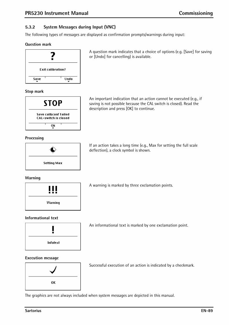
PR5230 Instrument Manual Commissioning
Sartorius EN-89
5.3.2 System Messages during Input (VNC)
The following types of messages are displayed as confirmation prompts/warnings during input:
Question mark
A question mark indicates that a choice of options (e.g. [Save] for saving or [Undo] for cancelling) is available.
Stop mark
An important indication that an action cannot be executed (e.g., if saving is not possible because the CAL switch is closed). Read the description and press [OK] to continue.
Processing
If an action takes a long time (e.g., Max for setting the full scale deflection), a clock symbol is shown.
Warning
A warning is marked by three exclamation points.
Informational text
An informational text is marked by one exclamation point.
Execution message
Successful execution of an action is indicated by a checkmark.
The graphics are not always included when system messages are depicted in this manual.
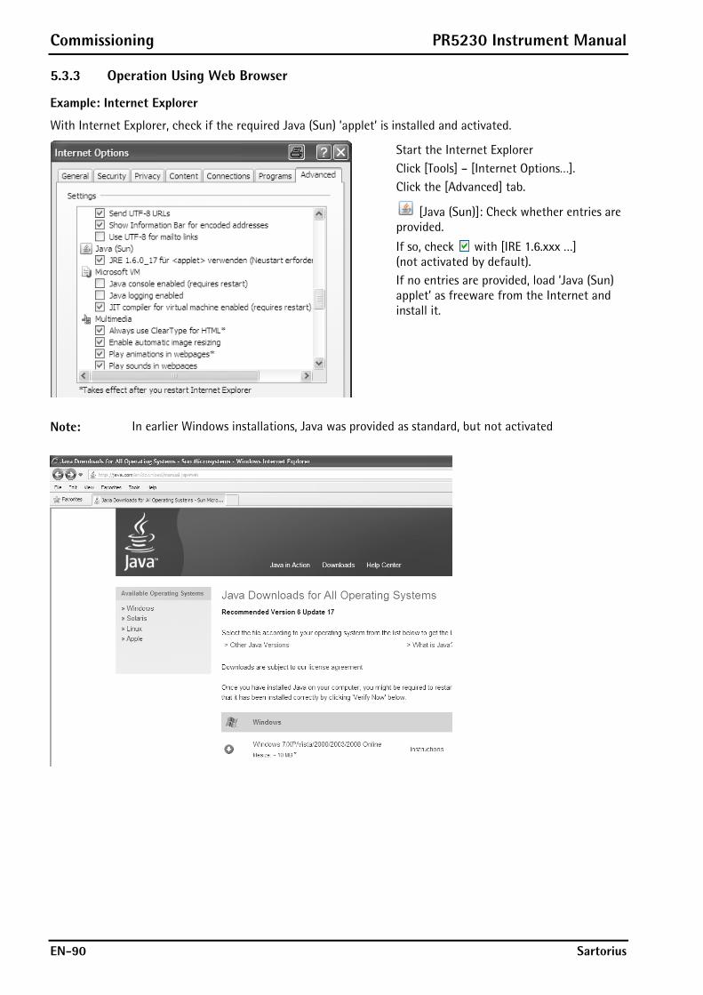
Commissioning PR5230 Instrument Manual
EN-90 Sartorius
5.3.3 Operation Using Web Browser
Example: Internet Explorer
With Internet Explorer, check if the required Java (Sun) ’applet’ is installed and activated.
Start the Internet Explorer Click [Tools] – [Internet Options…]. Click the [Advanced] tab.
[Java (Sun)]: Check whether entries are provided.
If so, check with [IRE 1.6.xxx …] (not activated by default).
If no entries are provided, load ’Java (Sun) applet’ as freeware from the Internet and install it.
Note: In earlier Windows installations, Java was provided as standard, but not activated

PR5230 Instrument Manual Commissioning
Sartorius EN-91
With the Internet browser, the [IP address] must be entered. Example:
The menu appears on the monitor. The line in brackets below the header corresponds to the device name specified in [Hostname].
[Remote Configuration (VNC)], [Remote Configuration (VNC) Pop up Window] For instrument operation using the VNC program without additional installation of VNC, see Chapter 5.3.1.
[Indicator], [Indicator Pop up Window]
The weight value is displayed with the unit and status symbols.
[Configuration Printout] Can be used for printing the configuration data as a text file, see Chapter 11.
[Logfiles] Display of log files
[Screenshot] Device display for saving the display
[Show error Log] Display of the error messages.
[Retrieve eventlog memory] Displaying the event log (see Chapter 5.9).
[Backup of Earom] Saving and restoring the configuration data (see Chapter 5.10).
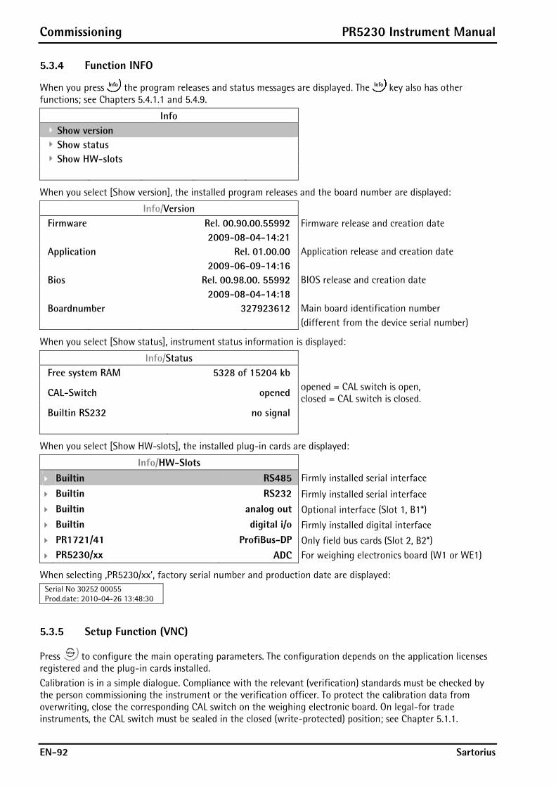
Commissioning PR5230 Instrument Manual
EN-92 Sartorius
5.3.4 Function INFO
When you press the program releases and status messages are displayed. The key also has other functions; see Chapters 5.4.1.1 and 5.4.9.
Info Show version Show status Show HW-slots
When you select [Show version], the installed program releases and the board number are displayed:
Info/Version
Firmware Rel. 00.90.00.55992 Firmware release and creation date 2009-08-04-14:21
Application Rel. 01.00.00 Application release and creation date 2009-06-09-14:16
Bios Rel. 00.98.00. 55992 BIOS release and creation date 2009-08-04-14:18
Boardnumber 327923612 Main board identification number (different from the device serial number)
When you select [Show status], instrument status information is displayed:
Info/Status Free system RAM 5328 of 15204 kb
CAL-Switch opened opened = CAL switch is open, closed = CAL switch is closed.
Builtin RS232 no signal
When you select [Show HW-slots], the installed plug-in cards are displayed:
Info/HW-Slots
Builtin RS485 Firmly installed serial interface
Builtin RS232 Firmly installed serial interface
Builtin analog out Optional interface (Slot 1, B1*)
Builtin digital i/o Firmly installed digital interface
PR1721/41 ProfiBus-DP Only field bus cards (Slot 2, B2*)
PR5230/xx ADC For weighing electronics board (W1 or WE1)
When selecting ‚PR5230/xx’, factory serial number and production date are displayed: Serial No 30252 00055 Prod.date: 2010-04-26 13:48:30
5.3.5 Setup Function (VNC)
Press to configure the main operating parameters. The configuration depends on the application licenses registered and the plug-in cards installed. Calibration is in a simple dialogue. Compliance with the relevant (verification) standards must be checked by the person commissioning the instrument or the verification officer. To protect the calibration data from overwriting, close the corresponding CAL switch on the weighing electronic board. On legal-for trade instruments, the CAL switch must be sealed in the closed (write-protected) position; see Chapter 5.1.1.
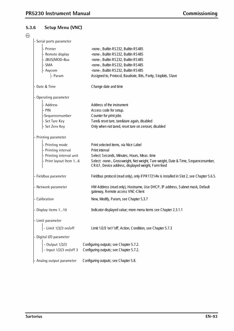
PR5230 Instrument Manual Commissioning
Sartorius EN-93
5.3.6 Setup Menu (VNC)
- Serial ports parameter
- Printer -none-, Builtin RS232, Builtin RS485 - Remote display -none-, Builtin RS232, Builtin RS485 - JBUS/MOD-Bus -none-, Builtin RS232, Builtin RS485 - SMA -none-, Builtin RS232, Builtin RS485 - Asycom -none-, Builtin RS232, Builtin RS485 - Param Assigned to, Protocol, Baudrate, Bits, Parity, Stopbits, Slave - Date & Time Change date and time - Operating parameter
- Address Address of the instrument - PIN Access code for setup. -Sequencenumber Counter for print jobs - Set Tare Key Tare& reset tare, tare&tare again, disabled - Set Zero Key Only when not tared, reset tare on zeroset, disabled - Printing parameter
- Printing mode Print selected items, via Nice Label - Printing interval Print interval - Printing interval unit Select: Seconds, Minutes, Hours, Meas. time - Print layout Item 1…6 Select: -none-, Grossweight, Net weight, Tare weight, Date & Time, Sequencenumber,
CR/LF, Device address, displayed weight, Form feed - Fieldbus parameter Fieldbus protocol (read only), only if PR1721/4x is installed in Slot 2, see Chapter 5.6.5. - Network parameter HW Address (read only), Hostname, Use DHCP, IP address, Subnet mask, Default
gateway, Remote access VNC-Client - Calibration New, Modify, Param, see Chapter 5.3.7
- Display items 1…10 Indicator displayed value; more menu items see Chapter 2.3.1.1 - Limit parameter
- Limit 1/2/3 on/off Limit 1/2/3 'on'/ 'off', Action, Condition, see Chapter 5.7.3
- Digital I/O parameter - Output 1/2/3 Configuring outputs; see Chapter 5.7.2.
- Input 1/2/3 on/off 3 Configuring outputs; see Chapter 5.7.2. - Analog output parameter Configuring outputs; see Chapter 5.8.
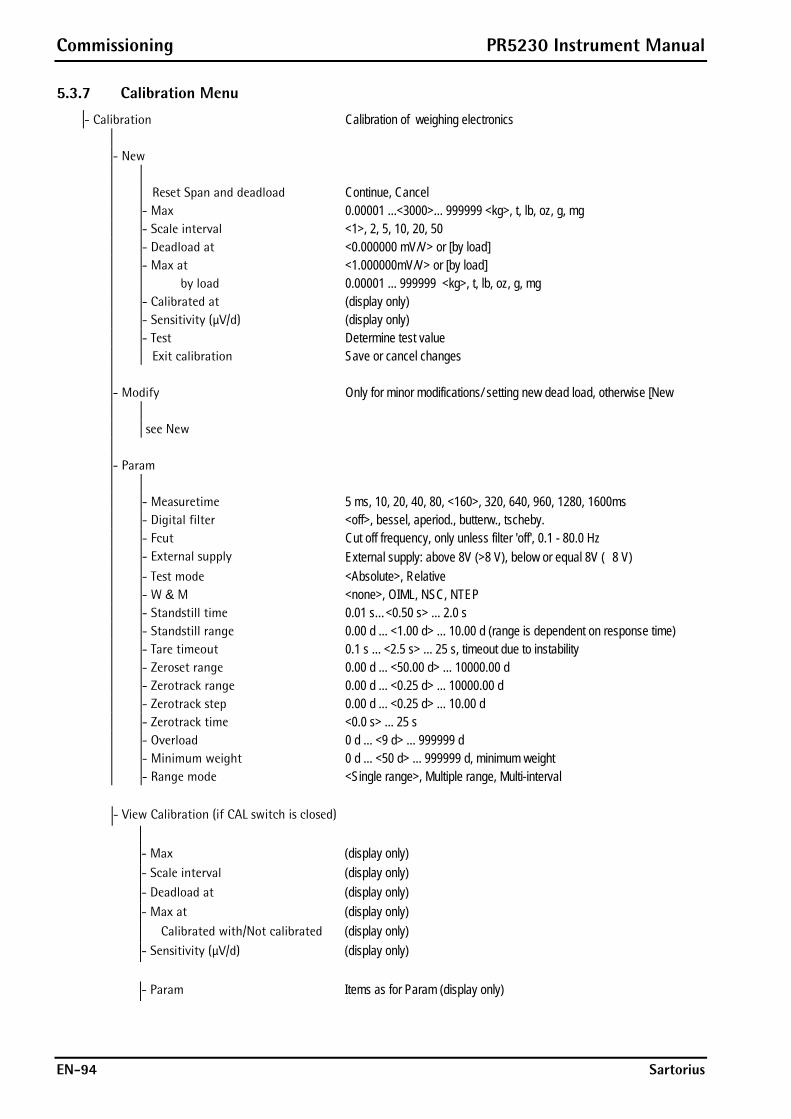
Commissioning PR5230 Instrument Manual
EN-94 Sartorius
5.3.7 Calibration Menu
- Calibration Calibration of weighing electronics - New Reset Span and deadload Continue, Cancel - Max 0.00001 ...<3000>... 999999 <kg>, t, lb, oz, g, mg - Scale interval <1>, 2, 5, 10, 20, 50 - Deadload at <0.000000 mV/V> or [by load] - Max at <1.000000mV/V> or [by load] by load 0.00001 ... 999999 <kg>, t, lb, oz, g, mg - Calibrated at (display only) - Sensitivity (μV/d) (display only) - Test Determine test value Exit calibration Save or cancel changes - Modify Only for minor modifications/ setting new dead load, otherwise [New see New - Param - Measuretime 5 ms, 10, 20, 40, 80, <160>, 320, 640, 960, 1280, 1600ms - Digital filter <off>, bessel, aperiod., butterw., tscheby. - Fcut Cut off frequency, only unless filter 'off', 0.1 - 80.0 Hz - External supply External supply: above 8V (>8 V), below or equal 8V ( 8 V) - Test mode <Absolute>, Relative - W & M <none>, OIML, NSC, NTEP - Standstill time 0.01 s…<0.50 s> ... 2.0 s - Standstill range 0.00 d ... <1.00 d> ... 10.00 d (range is dependent on response time) - Tare timeout 0.1 s ... <2.5 s> ... 25 s, timeout due to instability - Zeroset range 0.00 d ... <50.00 d> ... 10000.00 d - Zerotrack range 0.00 d ... <0.25 d> ... 10000.00 d - Zerotrack step 0.00 d ... <0.25 d> ... 10.00 d - Zerotrack time <0.0 s> ... 25 s - Overload 0 d ... <9 d> ... 999999 d - Minimum weight 0 d ... <50 d> ... 999999 d, minimum weight - Range mode <Single range>, Multiple range, Multi-interval - View Calibration (if CAL switch is closed) - Max (display only) - Scale interval (display only) - Deadload at (display only) - Max at (display only) Calibrated with/Not calibrated (display only) - Sensitivity (μV/d) (display only) - Param Items as for Param (display only)
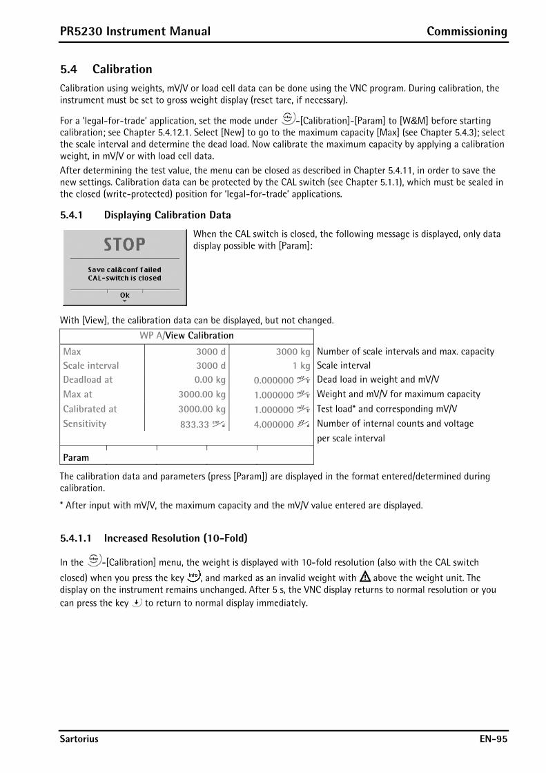
PR5230 Instrument Manual Commissioning
Sartorius EN-95
5.4 Calibration Calibration using weights, mV/V or load cell data can be done using the VNC program. During calibration, the instrument must be set to gross weight display (reset tare, if necessary).
For a ’legal-for-trade’ application, set the mode under -[Calibration]-[Param] to [W&M] before starting calibration; see Chapter 5.4.12.1. Select [New] to go to the maximum capacity [Max] (see Chapter 5.4.3); select the scale interval and determine the dead load. Now calibrate the maximum capacity by applying a calibration weight, in mV/V or with load cell data. After determining the test value, the menu can be closed as described in Chapter 5.4.11, in order to save the new settings. Calibration data can be protected by the CAL switch (see Chapter 5.1.1), which must be sealed in the closed (write-protected) position for ‘legal-for-trade’ applications.
5.4.1 Displaying Calibration Data
When the CAL switch is closed, the following message is displayed, only data display possible with [Param]:
With [View], the calibration data can be displayed, but not changed.
WP A/View Calibration
Max 3000 d 3000 kg Number of scale intervals and max. capacity Scale interval 3000 d 1 kg Scale interval Deadload at 0.00 kg 0.000000 Dead load in weight and mV/V
Max at 3000.00 kg 1.000000 Weight and mV/V for maximum capacity
Calibrated at 3000.00 kg 1.000000 Test load* and corresponding mV/V
Sensitivity 833.33 4.000000 Number of internal counts and voltage
per scale interval
Param
The calibration data and parameters (press [Param]) are displayed in the format entered/determined during calibration.
* After input with mV/V, the maximum capacity and the mV/V value entered are displayed.
5.4.1.1 Increased Resolution (10-Fold)
In the -[Calibration] menu, the weight is displayed with 10-fold resolution (also with the CAL switch
closed) when you press the key , and marked as an invalid weight with above the weight unit. The display on the instrument remains unchanged. After 5 s, the VNC display returns to normal resolution or you can press the key to return to normal display immediately.
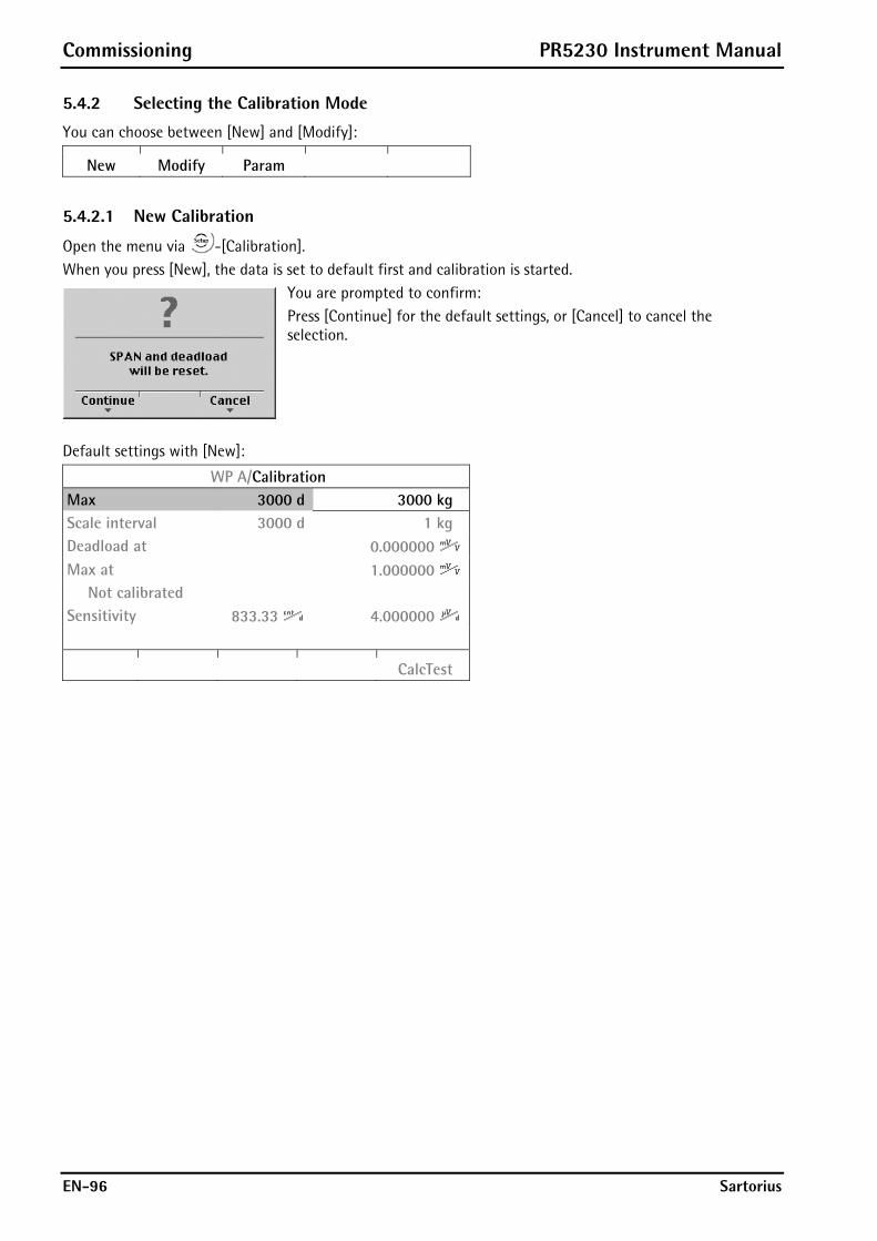
Commissioning PR5230 Instrument Manual
EN-96 Sartorius
5.4.2 Selecting the Calibration Mode
You can choose between [New] and [Modify]:
New Modify Param
5.4.2.1 New Calibration
Open the menu via -[Calibration]. When you press [New], the data is set to default first and calibration is started.
You are prompted to confirm: Press [Continue] for the default settings, or [Cancel] to cancel the selection.
Default settings with [New]:
WP A/Calibration Max 3000 d 3000 kg Scale interval 3000 d 1 kg Deadload at 0.000000 Max at 1.000000 Not calibrated Sensitivity 833.33 4.000000
CalcTest
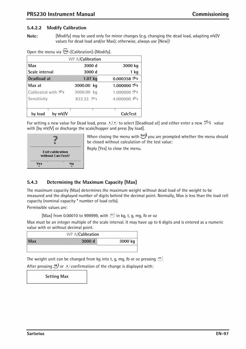
PR5230 Instrument Manual Commissioning
Sartorius EN-97
5.4.2.2 Modify Calibration
Note: [Modify] may be used only for minor changes (e.g. changing the dead load, adapting mV/V values for dead load and/or Max); otherwise, always use [New]!
Open the menu via -[Calibration]-[Modify].
WP A/Calibration Max 3000 d 3000 kg Scale interval 3000 d 1 kg Deadload at 1.07 kg 0.000358 Max at 3000.00 kg 1.000000 Calibrated with 3000.00 kg 1.000000 Sensitivity 833.33 4.000000
by load by mV/V CalcTest
For setting a new value for Dead load, press to select [Deadload at] and either enter a new value with [by mV/V] or discharge the scale/hopper and press [by load].
When closing the menu with you are prompted whether the menu should be closed without calculation of the test value: Reply [Yes] to close the menu.
5.4.3 Determining the Maximum Capacity [Max]
The maximum capacity (Max) determines the maximum weight without dead load of the weight to be measured and the displayed number of digits behind the decimal point. Normally, Max is less than the load cell capacity (nominal capacity * number of load cells). Permissible values are:
[Max] from 0.00010 to 999999, with in kg, t, g, mg, lb or oz Max must be an integer multiple of the scale interval. It may have up to 6 digits and is entered as a numeric value with or without decimal point.
WP A/Calibration
Max 3000 d 3000 kg
The weight unit can be changed from kg into t, g, mg, lb or oz pressing .
After pressing or confirmation of the change is displayed with:
Setting Max
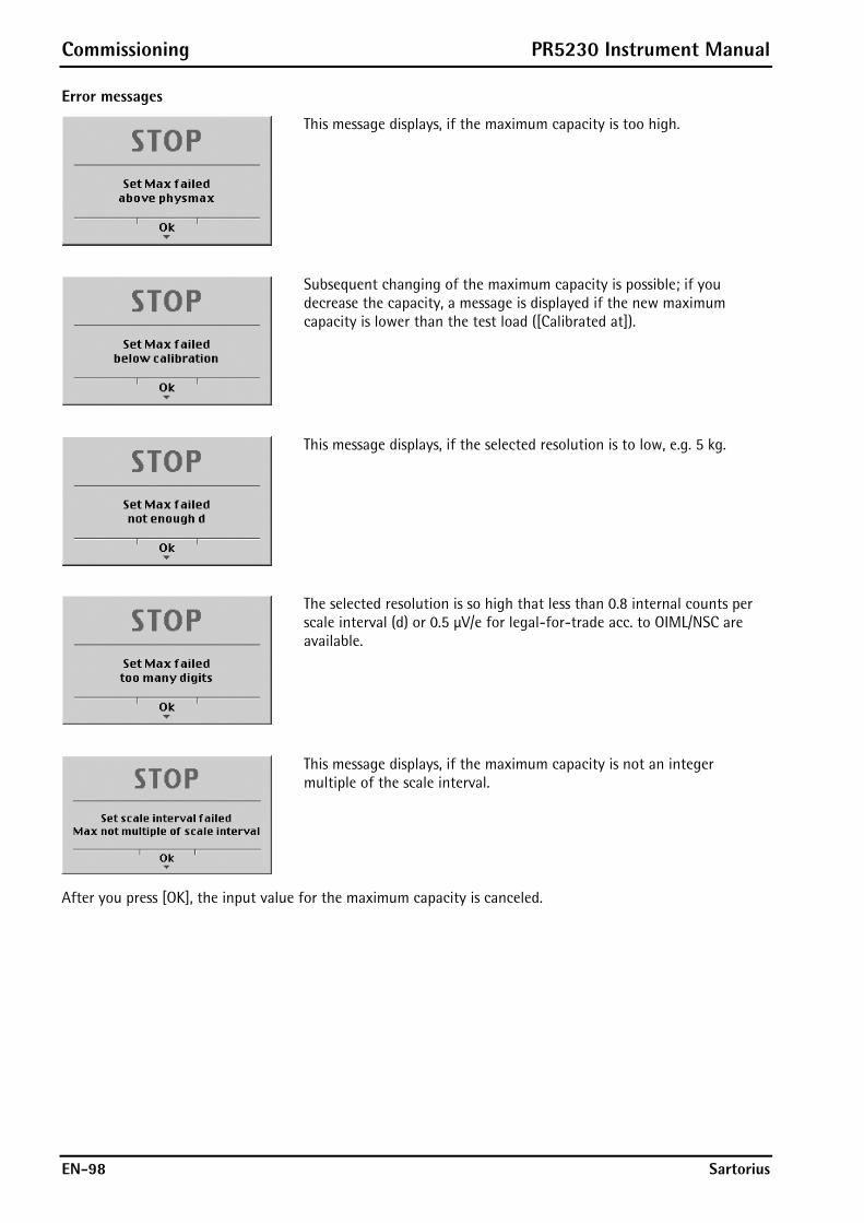
Commissioning PR5230 Instrument Manual
EN-98 Sartorius
Error messages
This message displays, if the maximum capacity is too high.
Subsequent changing of the maximum capacity is possible; if you decrease the capacity, a message is displayed if the new maximum capacity is lower than the test load ([Calibrated at]).
This message displays, if the selected resolution is to low, e.g. 5 kg.
The selected resolution is so high that less than 0.8 internal counts per scale interval (d) or 0.5 μV/e for legal-for-trade acc. to OIML/NSC are available.
This message displays, if the maximum capacity is not an integer multiple of the scale interval.
After you press [OK], the input value for the maximum capacity is canceled.

PR5230 Instrument Manual Commissioning
Sartorius EN-99
5.4.4 Determining the Scale Interval
WP A/Calibration
Max 3000 d 3000 kg
Scale interval 3000 d 1 kg The scale interval 1, 2, 5 10, 20 or 50
can be set by pressing .
The weight unit is taken from [Max] and cannot be changed here. The number of digits behind the decimal point must be determined already when entering [Max] as well.
After or confirmation of the change is displayed with:
Set Scale interval
The maximum capacity is not an integer multiple of the scale interval.
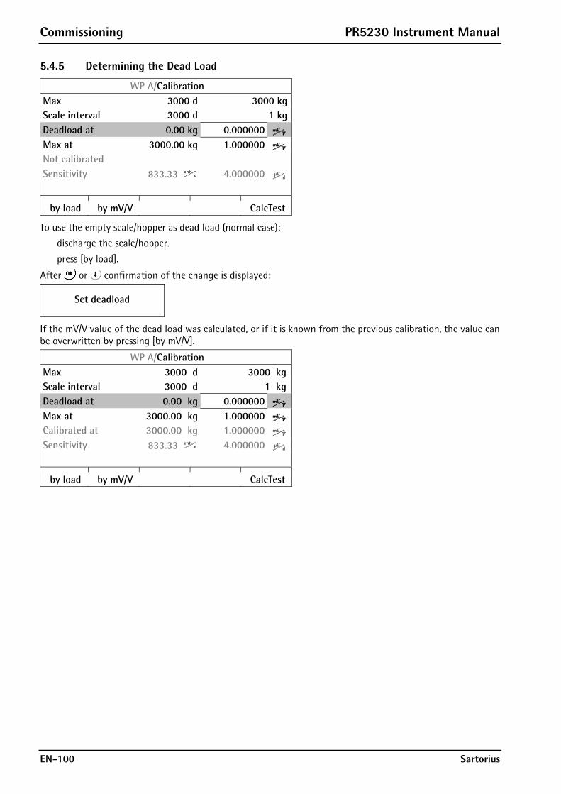
Commissioning PR5230 Instrument Manual
EN-100 Sartorius
5.4.5 Determining the Dead Load
WP A/Calibration Max 3000 d 3000 kgScale interval 3000 d 1 kgDeadload at 0.00 kg 0.000000Max at 3000.00 kg 1.000000Not calibrated Sensitivity 833.33 4.000000
by load by mV/V CalcTest
To use the empty scale/hopper as dead load (normal case):
discharge the scale/hopper.
press [by load].
After or confirmation of the change is displayed:
Set deadload
If the mV/V value of the dead load was calculated, or if it is known from the previous calibration, the value can be overwritten by pressing [by mV/V].
WP A/Calibration Max 3000 d 3000 kgScale interval 3000 d 1 kgDeadload at 0.00 kg 0.000000Max at 3000.00 kg 1.000000 Calibrated at 3000.00 kg 1.000000 Sensitivity 833.33 4.000000
by load by mV/V CalcTest
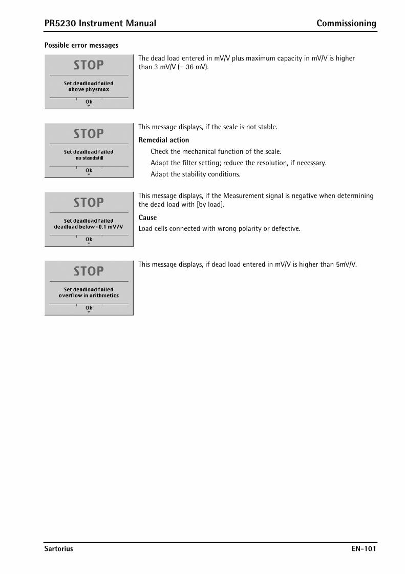
PR5230 Instrument Manual Commissioning
Sartorius EN-101
Possible error messages
The dead load entered in mV/V plus maximum capacity in mV/V is higher than 3 mV/V (= 36 mV).
This message displays, if the scale is not stable.
Remedial action Check the mechanical function of the scale.
Adapt the filter setting; reduce the resolution, if necessary.
Adapt the stability conditions.
This message displays, if the Measurement signal is negative when determining the dead load with [by load].
Cause Load cells connected with wrong polarity or defective.
This message displays, if dead load entered in mV/V is higher than 5mV/V.
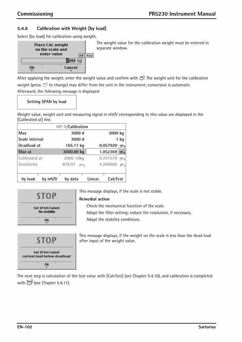
Commissioning PR5230 Instrument Manual
EN-102 Sartorius
5.4.6 Calibration with Weight [by load]
Select [by load] for calibration using weight.
The weight value for the calibration weight must be entered in separate window.
After applying the weight, enter the weight value and confirm with . The weight unit for the calibration
weight (press to change) may differ from the unit in the instrument; conversion is automatic. Afterward, the following message is displayed:
Setting SPAN by load
Weight value, weight unit and measuring signal in mV/V corresponding to this value are displayed in the [Calibrated at] line.
WP A/Calibration Max 3000 d 3000 kgScale interval 3000 d 1 kgDeadload at 165.11 kg 0.057920Max at 3000.00 kg 1.052369Calibrated at 2000 10kg 0.701579Sensitivity 876.97 4.209600
by load by mV/V by data Linear. CalcTest
This message displays, if the scale is not stable.
Remedial action Check the mechanical function of the scale.
Adapt the filter setting; reduce the resolution, if necessary.
Adapt the stability conditions.
This message displays, if the weight on the scale is less than the dead load after input of the weight value.
The next step is calculation of the test value with [CalcTest] (see Chapter 5.4.10), and calibration is completed
with (see Chapter 5.4.11).
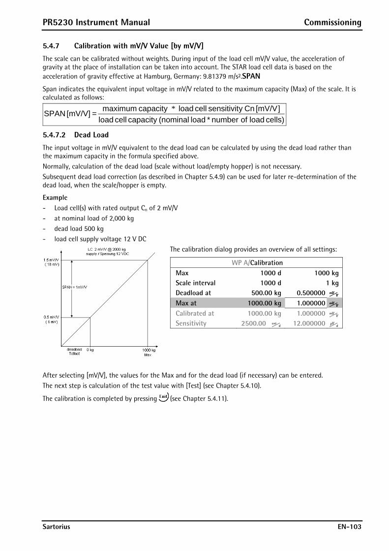
PR5230 Instrument Manual Commissioning
Sartorius EN-103
5.4.7 Calibration with mV/V Value [by mV/V]
The scale can be calibrated without weights. During input of the load cell mV/V value, the acceleration of gravity at the place of installation can be taken into account. The STAR load cell data is based on the acceleration of gravity effective at Hamburg, Germany: 9.81379 m/s².SPAN
Span indicates the equivalent input voltage in mV/V related to the maximum capacity (Max) of the scale. It is calculated as follows:
cells) load of number * load (nominalcapacity cell load][mV/V Cn ysensitivit cell load capacity maximum = [mV/V] SPAN *
5.4.7.2 Dead Load
The input voltage in mV/V equivalent to the dead load can be calculated by using the dead load rather than the maximum capacity in the formula specified above. Normally, calculation of the dead load (scale without load/empty hopper) is not necessary. Subsequent dead load correction (as described in Chapter 5.4.9) can be used for later re-determination of the dead load, when the scale/hopper is empty.
Example - Load cell(s) with rated output Cn of 2 mV/V - at nominal load of 2,000 kg - dead load 500 kg - load cell supply voltage 12 V DC
The calibration dialog provides an overview of all settings:
WP A/Calibration Max 1000 d 1000 kgScale interval 1000 d 1 kgDeadload at 500.00 kg 0.500000Max at 1000.00 kg 1.000000Calibrated at 1000.00 kg 1.000000Sensitivity 2500.00 12.000000
After selecting [mV/V], the values for the Max and for the dead load (if necessary) can be entered. The next step is calculation of the test value with [Test] (see Chapter 5.4.10).
The calibration is completed by pressing (see Chapter 5.4.11).

Commissioning PR5230 Instrument Manual
EN-104 Sartorius
5.4.8 Calibration with Load Cell Data (smart calibration)
This is the simplest method for 'calibration without weights', as no calculation is necessary.
WP A/Calibration Max 3000 d 3000 kgScale interval 3000 d 1 kgDeadload at 3.00 kg 0.001000Max at 3000.00 kg 0.000000Not calibrated Sensitivity 833.33 4.000000
by load by mV/V by data Linear. CalcTest
Start by pressing [by data].
WP A/Calibration/Load cell configuration
Number of load cells 4Nominal load 3000 kgGravity 9.81379 m/s²Hysteresis error not specifiedCertified data all LC sameLC sensitivity 1.000000
Enter Calc
WP A/Calibration/Load cell configuration
LC resistance 600.000 ¥
Enter Calc
[Number of load cells] Number of load cells connected in parallel (1, 2...<4>...9, 10)
[Nominal load] Max. capacity Emax of a load cell (not the overall nominal weight of the scale!)
[Gravity] Acceleration of gravity at the place of installation; default is the value for Hamburg, Germany 9.81379 m/s².
[Hysteresis error] When switching from [Not specified] to [Specified], values for [Correction A/B] must be filled in. The data is given on the load cell certificate.
[Certified data], [LC sensitivity], [LC resistance] With [all LC same] only 1 value for the sensitivity [LC sensitivity] and the output resistance [LC resistance] must be filled in. With [each LC specific] individual values for each load cell are requested.
[Calc] The mV/V value is calculated and after confirmation with [OK], the calculated mV/V value is stored in the calibration data.
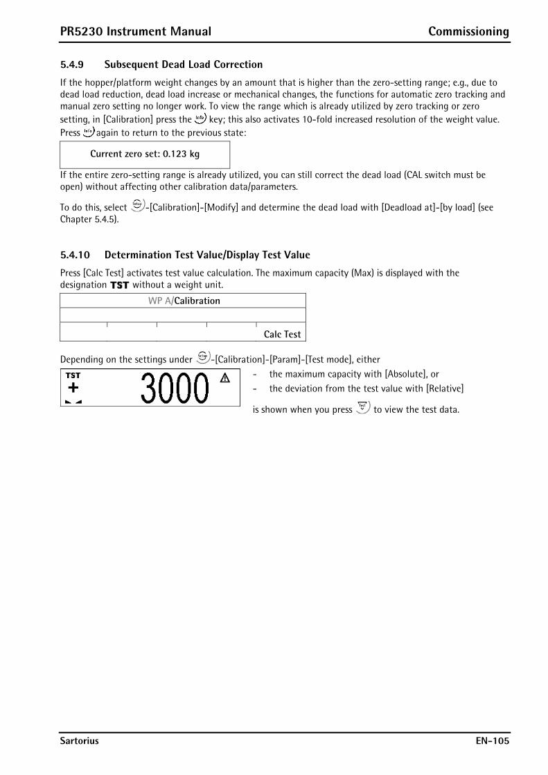
PR5230 Instrument Manual Commissioning
Sartorius EN-105
5.4.9 Subsequent Dead Load Correction
If the hopper/platform weight changes by an amount that is higher than the zero-setting range; e.g., due to dead load reduction, dead load increase or mechanical changes, the functions for automatic zero tracking and manual zero setting no longer work. To view the range which is already utilized by zero tracking or zero setting, in [Calibration] press the key; this also activates 10-fold increased resolution of the weight value. Press again to return to the previous state:
Current zero set: 0.123 kg
If the entire zero-setting range is already utilized, you can still correct the dead load (CAL switch must be open) without affecting other calibration data/parameters.
To do this, select -[Calibration]-[Modify] and determine the dead load with [Deadload at]-[by load] (see Chapter 5.4.5).
5.4.10 Determination Test Value/Display Test Value
Press [Calc Test] activates test value calculation. The maximum capacity (Max) is displayed with the designation without a weight unit.
WP A/Calibration
Calc Test
Depending on the settings under -[Calibration]-[Param]-[Test mode], either
- the maximum capacity with [Absolute], or - the deviation from the test value with [Relative]
is shown when you press to view the test data.
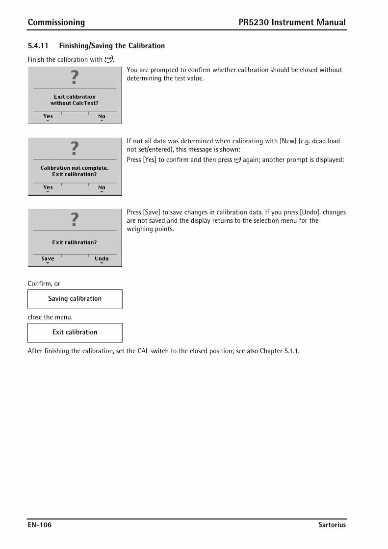
Commissioning PR5230 Instrument Manual
EN-106 Sartorius
5.4.11 Finishing/Saving the Calibration
Finish the calibration with .
You are prompted to confirm whether calibration should be closed without determining the test value.
If not all data was determined when calibrating with [New] (e.g. dead load not set/entered), this message is shown: Press [Yes] to confirm and then press again; another prompt is displayed:
Press [Save] to save changes in calibration data. If you press [Undo], changes are not saved and the display returns to the selection menu for the weighing points.
Confirm, or
Saving calibration
close the menu.
Exit calibration
After finishing the calibration, set the CAL switch to the closed position; see also Chapter 5.1.1.
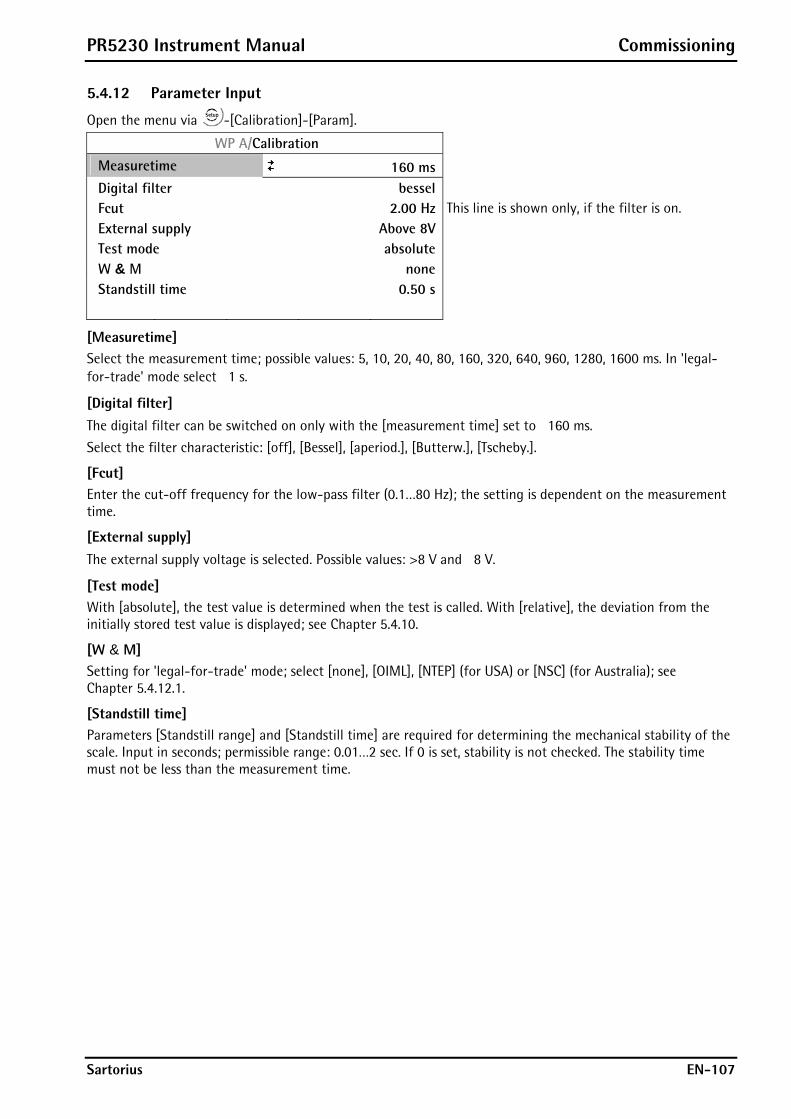
PR5230 Instrument Manual Commissioning
Sartorius EN-107
5.4.12 Parameter Input
Open the menu via -[Calibration]-[Param].
WP A/Calibration
Measuretime 160 ms
Digital filter bessel Fcut 2.00 Hz This line is shown only, if the filter is on. External supply Above 8V Test mode absolute W & M none Standstill time 0.50 s
[Measuretime] Select the measurement time; possible values: 5, 10, 20, 40, 80, 160, 320, 640, 960, 1280, 1600 ms. In 'legal-for-trade' mode select 1 s.
[Digital filter] The digital filter can be switched on only with the [measurement time] set to 160 ms.
Select the filter characteristic: [off], [Bessel], [aperiod.], [Butterw.], [Tscheby.].
[Fcut] Enter the cut-off frequency for the low-pass filter (0.1…80 Hz); the setting is dependent on the measurement time.
[External supply] The external supply voltage is selected. Possible values: >8 V and 8 V.
[Test mode] With [absolute], the test value is determined when the test is called. With [relative], the deviation from the initially stored test value is displayed; see Chapter 5.4.10.
[W & M] Setting for 'legal-for-trade' mode; select [none], [OIML], [NTEP] (for USA) or [NSC] (for Australia); see Chapter 5.4.12.1.
[Standstill time] Parameters [Standstill range] and [Standstill time] are required for determining the mechanical stability of the scale. Input in seconds; permissible range: 0.01…2 sec. If 0 is set, stability is not checked. The stability time must not be less than the measurement time.
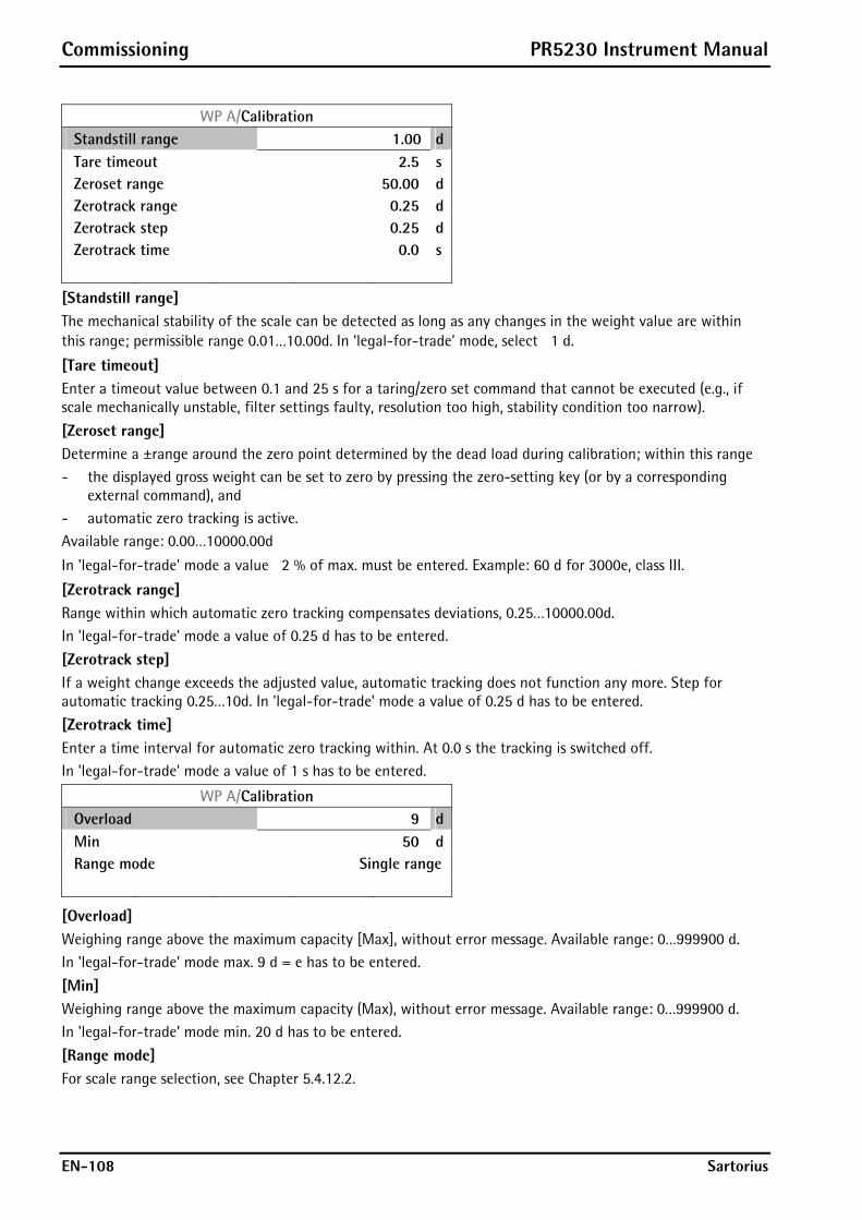
Commissioning PR5230 Instrument Manual
EN-108 Sartorius
WP A/Calibration Standstill range 1.00 d Tare timeout 2.5 s Zeroset range 50.00 d Zerotrack range 0.25 d Zerotrack step 0.25 d Zerotrack time 0.0 s
[Standstill range] The mechanical stability of the scale can be detected as long as any changes in the weight value are within this range; permissible range 0.01…10.00d. In ‘legal-for-trade’ mode, select 1 d.
[Tare timeout] Enter a timeout value between 0.1 and 25 s for a taring/zero set command that cannot be executed (e.g., if scale mechanically unstable, filter settings faulty, resolution too high, stability condition too narrow).
[Zeroset range] Determine a ±range around the zero point determined by the dead load during calibration; within this range - the displayed gross weight can be set to zero by pressing the zero-setting key (or by a corresponding
external command), and - automatic zero tracking is active. Available range: 0.00…10000.00d
In 'legal-for-trade' mode a value 2 % of max. must be entered. Example: 60 d for 3000e, class III.
[Zerotrack range] Range within which automatic zero tracking compensates deviations, 0.25…10000.00d. In 'legal-for-trade' mode a value of 0.25 d has to be entered.
[Zerotrack step] If a weight change exceeds the adjusted value, automatic tracking does not function any more. Step for automatic tracking 0.25…10d. In 'legal-for-trade' mode a value of 0.25 d has to be entered.
[Zerotrack time] Enter a time interval for automatic zero tracking within. At 0.0 s the tracking is switched off. In 'legal-for-trade' mode a value of 1 s has to be entered.
WP A/Calibration Overload 9 d Min 50 d Range mode Single range
[Overload] Weighing range above the maximum capacity [Max], without error message. Available range: 0…999900 d. In 'legal-for-trade' mode max. 9 d = e has to be entered.
[Min] Weighing range above the maximum capacity (Max), without error message. Available range: 0…999900 d. In 'legal-for-trade' mode min. 20 d has to be entered.
[Range mode] For scale range selection, see Chapter 5.4.12.2.

PR5230 Instrument Manual Commissioning
Sartorius EN-109
5.4.12.1 Legal-for-Trade Operation
Under -[Calibration]-[Param]-[W&M] you can choose between: [none] a legal-for-trade mode [OIML], [NTEP] or [NSC].
[none] [OIML] [NTEP] [NSC] Gross weight display B B G G
0,125 mV/V at 30000 d
0,125 mV/V at 3000 e
0,125 mV/V at 3000 e
0,125 mV/V at 3000 e
0,25 mV/V at 60000 d
0,25 mV/V at 6000 e
0,25 mV/V at 6000 e
0,25 mV/V at 6000 e
Min. meas. signal
0,42 mV/V at 10000 e
0,42 mV/V at 10000 e
0,42 mV/V at 10000 e
If legal-for-trade operation is selected, the parameters (zero tracking etc.) must be set accordingly; they are not checked. The relevant CAL switches (see Chapter 5.1.1) must be sealed in the closed position.
5.4.12.2 Multiple Range Scale/Multi-Interval Scale
Range selection is controlled by three parameters under -[Calibration]-[Param].
WP A/Calibration
Range mode Multiple range Select [Multiple range] or [Multi-interval]
Range limit 1 1000 kg Switch point from range 1 to 2
Range limit 2 2000 kg Switch point from range 2 to 3
Multiple Range Scale
With [Range mode] = [Multiple range], the scale has up to 3 ranges with different resolutions. The corresponding ranges are indicated above the mass unit as follows:
, or The switch points [Range limit 1] and [Range limit 2] are the range limits. As soon as the gross weight exceeds range 1, the next higher range with the next higher interval becomes valid (1->2->5->10->20->50->100->200). When reducing the weight, the interval of the previous range is kept. When the gross weight is 0,25 d of range 1 and the scale is stable and not tared, the scale returns to range 1 with the corresponding interval.
Multi-Interval Scale
With [Range mode] = [Multi-interval], the scale has up to three ranges with different resolution. Each range has the corresponding interval. Unlike [Multiple range], switching the interval is also triggered by weight reduction; i.e., when the weight drops below the range limits. During calibration, the multiple range/multi-interval function is always switched off.
Display VNC
The weight display header includes the current range (R1, R2, and R3), Max, Min and d (or e with legal-for-trade instruments) (Example: multiple range scale in range 2):
WP-A R2 MaxMin
2000kg d= 2kg40kg
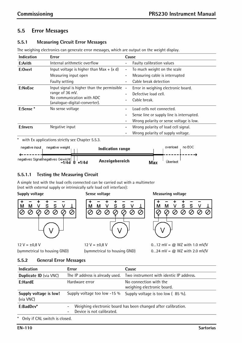
Commissioning PR5230 Instrument Manual
EN-110 Sartorius
5.5 Error Messages
5.5.1 Measuring Circuit Error Messages
The weighing electronics can generate error messages, which are output on the weight display.
Indication Error Cause E:Arith Internal arithmetic overflow - Faulty calibration values
E:Overl Input voltage is higher than Max + (x d) - To much weight on the scale
Measuring input open - Measuring cable is interrupted
Faulty setting - Cable break detection
E:NoEoc Input signal is higher than the permissible range of 36 mV. No communication with ADC (analogue-digital-converter).
- Error in weighing electronic board. - Defective load cell. - Cable break.
E:Sense * No sense voltage - Load cells not connected. - Sense line or supply line is interrupted. - Wrong polarity or sense voltage is low.
E:Invers Negative input - Wrong polarity of load cell signal. - Wrong polarity of supply voltage.
* with Ex applications strictly see Chapter 5.5.3.
5.5.1.1 Testing the Measuring Circuit
A simple test with the load cells connected can be carried out with a multimeter (not with external supply or intrinsically safe load cell interface):
Supply voltage Sense voltage Measuring voltage
12 V = ±0,8 V (symmetrical to housing GND)
12 V = ±0,8 V (symmetrical to housing GND)
0…12 mV = @ WZ with 1.0 mV/V 0…24 mV = @ WZ with 2.0 mV/V
5.5.2 General Error Messages
Indication Error Cause Duplicate ID (via VNC) The IP address is already used. Two instrument with identic IP address.
E:HardE Hardware error No connection with the weighing electronic board.
Supply voltage is low! (via VNC)
Supply voltage too low -15 % Supply voltage is too low ( 85 %).
E:BadDev* - Weighing electronic board has been changed after calibration. - Device is not calibrated.
* Only if CAL switch is closed.

PR5230 Instrument Manual Commissioning
Sartorius EN-111
5.5.3 Error Messages with Ex Applications
In the event of load cell supply faults, the following error message is displayed:
E:Sense (via VNC: No sense voltage)
Two different faults are possible, which are displayed by two LEDs on the weighing electronics board.
V120
V304
V120 lit: Sense voltage is too low.
The cause can be a line break in the power supply and/or Sense lines.
V304 lit: Current limiting for the load cell supply is active -> Sense voltage is too low.
The load cell supply current monitoring activates current limiting, if there is a short circuit in the load cell supply lines, the load cell resistance is too low (e.g. too many load cells connected), see also Chapter 3.2.8.2.
The current is limited to 96 mA.
After fault removal, current limiting must be de-activated. This can be achieved by switching off the instrument and/or disconnecting the load cells.

Commissioning PR5230 Instrument Manual
EN-112 Sartorius
5.6 Configuring General Parameters The configuration of parameters which are not related to the weighing electronics is divided into several sections (see Chapter 5.3.6 ).
5.6.1 Serial Interfaces [Serial ports]
To configure the serial interfaces, press -[Serial ports parameter].
Press .
Press to select the specific protocol.
Press to select the respective port.
Example of Selection
Setup/Serial ports Printer -none-
Remote display Builtin RS232
JBUS/MOD-Bus Builtin RS485 SMA -none- Asycom -none-
Param
[Printer]
Select the serial interface to which the printer is connected. Select [Param] to define the transfer characteristics.
Press to select the specific parameter.
Press to select the respective values.
Setup/Serial ports/Builtin RS232
Assigned to Printer
Protocol XON/XOFF XON/XOFF, RTS/CTS, W&M Printer, no printer Baudrate 9600 bd 300, 600, .... 19200, 38400 Bits 7 7, 8 Parity even no, odd, even Stopbits 1 1, 2 Output mode raw raw, CR/LF translation

PR5230 Instrument Manual Commissioning
Sartorius EN-113
[Remote display]
Select the serial interface to which the remote display is connected and then select [Param] to define the [Baudrate] and the remote display type [Mode] connected.
Press to select the specific parameter.
Press to select the respective values. The light gray displayed parameter cannot be changed.
Setup/Serial ports/Builtin RS485 Assigned to Remote display Protocol Remote display
Baudrate 9600 bd 300, 600, 1200, 2400, 4800, 9600 Bits 7 Parity even Stopbits 1 Mode multiple transmitters Several remote displays are connected. Device ID A Address of the instrument Next Device ID B Next address of the instrument
If only 1 instrument is connected to a remote display (normal case), [Mode] must be set to [single transmitter]. For PR1577 remote display [PR1577 mode] has to be set. If more than 1 instrument is connected to 1 remote display, [Mode] must be set to [multiple transmitters]. At [Device Id] the own instrument address (A, B, C ...) has to be entered, at [Next Device Id] the address of the subsequent instrument has to be entered
Press to return to the menu ‚Serial ports’.

Commissioning PR5230 Instrument Manual
EN-114 Sartorius
[JBUS/MOD-Bus]
To configure the serial interfaces, press -[Serial ports parameter] to select a RS-232 interface (e.g. JBUS/MOD-Bus).
Press to select the specific parameter.
Press to select the respective values. The light gray displayed parameter cannot be changed.
Setup/Serial ports/Builtin RS232 Assigned to JBUS/MOD-Bus Protocol JBUS/MOD-Bus
Baudrate 9600 bd 300, 600, .... 19200, 38400 Bits 8 Parity even no, odd, even Stopbits 1 Slave 1
Press to return to the menu ‚Serial ports’.
Press to return to the setup menu of [Serial ports parameter]. When you close this menu, the following messages are displayed if at least one setting was changed:
Save settings
Starting JBUS/MOD-Bus
The JBUS/MOD bus protocol is described in Chapter 5.8.
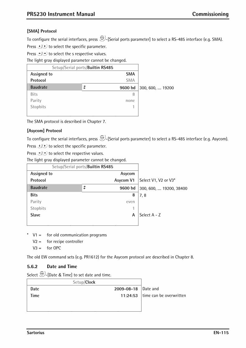
PR5230 Instrument Manual Commissioning
Sartorius EN-115
[SMA] Protocol
To configure the serial interfaces, press -[Serial ports parameter] to select a RS-485 interface (e.g. SMA).
Press to select the specific parameter.
Press to select the s respective values. The light gray displayed parameter cannot be changed.
Setup/Serial ports/Builtin RS485 Assigned to SMA Protocol SMA
Baudrate 9600 bd 300, 600, .... 19200 Bits 8 Parity none Stopbits 1
The SMA protocol is described in Chapter 7.
[Asycom] Protocol
To configure the serial interfaces, press -[Serial ports parameter] to select a RS-485 interface (e.g. Asycom).
Press to select the specific parameter.
Press to select the respective values. The light gray displayed parameter cannot be changed.
Setup/Serial ports/Builtin RS485
Assigned to Asycom
Protocol Asycom V1 Select V1, V2 or V3*
Baudrate 9600 bd 300, 600, .... 19200, 38400 Bits 8 7, 8 Parity even
Stopbits 1
Slave A Select A - Z
* V1 = for old communication programs V2 = for recipe controller V3 = for OPC
The old EW command sets (e.g. PR1612) for the Asycom protocol are described in Chapter 8.
5.6.2 Date and Time
Select -[Date & Time] to set date and time.
Setup/Clock
Date 2009-08-18 Date and
Time 11:24:53 time can be overwritten

Commissioning PR5230 Instrument Manual
EN-116 Sartorius
5.6.3 Operating parameters
Define the basic operating parameters under -[Operating parameter].
Press to select the specific parameter.
Press to select the respective values.
Setup/Operating parameter Address A Select A - Z
PIN ****** Enter the access code
Sequencenumber 28 Counter for print jobs SetTareKey tare & reset tare tare & reset tare, tare & tare again, disabled SetZeroKey only when not tared Only when not tared, reset tare on zeroset,
disabled
[Address]
Device address; e.g. for print-out.
[PIN]
The access code can be used to protect the [Setup] from unauthorized operation. Enter a number with up to 6 digits. As long as you are in this menu, the value can be overwritten as required.
SUPER-PIN If the PIN-Code is lost, the Setup can be unlocked with Super-PIN '212223'.
[Sequencenumber]
The number (counter for print jobs) may appear (selectable) on the print-out too, is incremented automatically (max. 999999) and can be set here.
[SetTareKey]
The function of the tare key on the keypad can be configured: [tare & reset tare]: the scale is tared if it was not tared previously; otherwise, tare is reset. [tare & tare again]: when you press the [Tare] key, the current value is stored in the tare memory and a net weight of 0 is displayed. [disabled]: The key has no function.
[SetZeroKey]
[only when not tared]: The function of the zero-setting key on the keypad can be limited to gross mode. [reset tare on zeroset]: The zero-setting key switches the scale to gross mode automatically. If the zero-setting key with these settings has no effect, the configured zero-setting range (around the zero-point set with the dead load) is already utilized due to a previous zero-setting operation and/or automatic zero setting. [disabled]: The key has no function. Press to return to the setup menu. This message is displayed:
Press [Yes] to save the data, or [No] to close the menu without changing data.

PR5230 Instrument Manual Commissioning
Sartorius EN-117
5.6.4 Printing parameter
Define the basic printing parameters under -[Printing parameter].
Press to select the specific parameter.
Press to select the respective values.
Setup/Printing parameter
Print mode Cyclic Cyclic, Cyclic with enable, Triggered
Printing interval 5 Enter value
Printing interval unit Seconds Seconds, Minutes, Hours, Measures
PrintlayoutItem1 Sequencenumber
PrintlayoutItem2 Grossweight
PrintlayoutItem3 Date & Time
PrintlayoutItem4 CR/LF
PrintlayoutItem5 Form feed
PrintlayoutItem6 -none-
[Cyclic]
Cyclic printing with adjusted parameters.
[Cyclic with enable]
Continuous printing.
[Triggered]
Singular printing.
[Sequencenumber]
Current sequence number, max. 6 digits, after #999999 the #000001 is following.
[CR/LF], [Form feed]
Carriage returns and line feed, form feed.
[Device address]
Address of the instrument (A, B ... Z).
[-none-]
Nothing is printed. The function can be used for printing less than 6 data items.
[Displayed weight], [Grossweight], [Net weight], [Tare weight]
The displayed gross, net or tare weight is printed. If [OIML], [NTEP] or [NSC] has been selected, printing is done only, if the stability criteria is fulfilled, the weight is shown in '< >'. For [NTEP] or [NSC] the gross weight is indicated with G (else B).

Commissioning PR5230 Instrument Manual
EN-118 Sartorius
[Date & Time]
The date and time are printed as DD.MM.YYYY HH:MM:SS
Example for printing
PrintlayoutItem1 Date & Time
PrintlayoutItem2 Sequencenumber
PrintlayoutItem3 Grossweight
PrintlayoutItem4 Net weight
PrintlayoutItem5 CR/LF
PrintlayoutItem6 -none-
5.6.5 Fieldbus parameter
This menu item can only be selected if a fieldbus card is installed in slot 2. Which protocol is displayed automatically depends on the Fieldbus card installed: [ProfiBus-DP] for PR1721/41, [InterBus-S] for PR1721/42, [DeviceNet] for PR1721/44, [ProfiNet I/O] for PR1721/46 and [EtherNet-IP] for PR1721/47.
Define the fieldbus parameters under -[Fieldbus parameter]. Which additional parameters are required, depends on the interface type.
Press to select the specific parameter.
Press to select the respective values.
[ProfiBus-DP]
Setup/Fieldbus parameter
fieldbus protocol ProfiBus-DP
ProfiBus-DP address 1 Enter address
[InterBus-S]
Setup/Fieldbus parameter
Fieldbus protocol InterBus-S
[DeviceNet]
Setup/Fieldbus parameter
Fieldbus protocol DeviceNet
DeviceNet baudrate 500k Select 500, 250 or 125 k
DeviceNet MAC-ID 1 Enter address 1 ... 62
[CC-Link]
Setup/Fieldbus parameter
Fieldbus protocol CC-Link
CC-Link baudrate 156k Select 156k, 625k, 2.5M, 5M or 10M
CC-Link ID 1 Enter address

PR5230 Instrument Manual Commissioning
Sartorius EN-119
[ProfiNet I/O]
Setup/Fieldbus parameter Fieldbus protocol ProfiNet I/O
Use DHCP off Select on/off
IP address 192.168.1.1 Enter IP address Subnet mask 255.255.255.0 Enter Subnet mask
[EtherNet/IP]
Setup/Fieldbus parameter Fieldbus protocol Ethernet/IP
Use DHCP off Select on/off
IP address 192.168.1.1 Enter IP address Subnet mask 255.255.255.0 Enter Subnet mask
Press to return to the setup menu. This message is displayed:
Reply [YES] to save the data, or [NO] to close the menu without changing data.

Commissioning PR5230 Instrument Manual
EN-120 Sartorius
5.6.6 Network parameter
You can configure settings for the network connections (built-in LAN adapter).
Define the network parameters under -[Network parameter].
Press to select the specific parameter.
Press to select the respective values. The light gray displayed parameter cannot be changed.
Setup/Network parameter
HW address 00:90:6C:FB:E9:85 Fixed address determined by the instrument
Hostname HOPPER 1 Device name; user-definable
Use DHCP Address is assigned by the server
IP Address 172.24.20.57 Address assigned by the server
Subnetmask 255.255.240.0 Mask for permissible IP address range
Default gateway 172.24.16.1 IP number for gateway
Remote access
VNC-Client 255.255.255.255 Permissible client for operation of the instrument
[Hostname]
Caution! The host name must be unique in the network!
The device name is subject to the following restrictions: - Minimum number of characters: 2, maximum number of characters: 24 - The first character must be a letter. - Spaces are not permitted. - 0-9, A-Z (upper and lower case letters are not distinguished) are permitted.
- ‚-’ or ‚.’ may be included, but neither at the end nor in succession.
[Use DHCP]
If the checkbox has been marked, the server defines the IP address automatically.
[VNC-Client]
You can configure access permissions for the address:
VNC-Client 0.0.0.0. Access over VNC not permitted VNC-Client 172.24.21.101 Access only from client machine with this address VNC-Client 172.24.21.255 Access from any client with address within range 172.24.21.1 - ..254 VNC-Client 255.255.255.255 Access from client with any address
Note: When setting [IP address], [Subnet mask] and [Standard gateway], please consult with your network administrator.

PR5230 Instrument Manual Commissioning
Sartorius EN-121
5.6.7 Display items
Define the display items under -[Display items].
Press to select the specific items.
Press to select the respective parameter.
Setup/Display items
Item 1 Indicator value Cannot be changed
Item 2 Bargraph
Item 3 Gross
Item 4 Digital inputs
Item 5 Fieldbus LEDs
Item 6 Digital outputs
Item 7 Hostname
Item 8 IP-address
Item 9 Limits
Item 10 Analog output
For information on the settings, see Chapter 2.3.1.1.
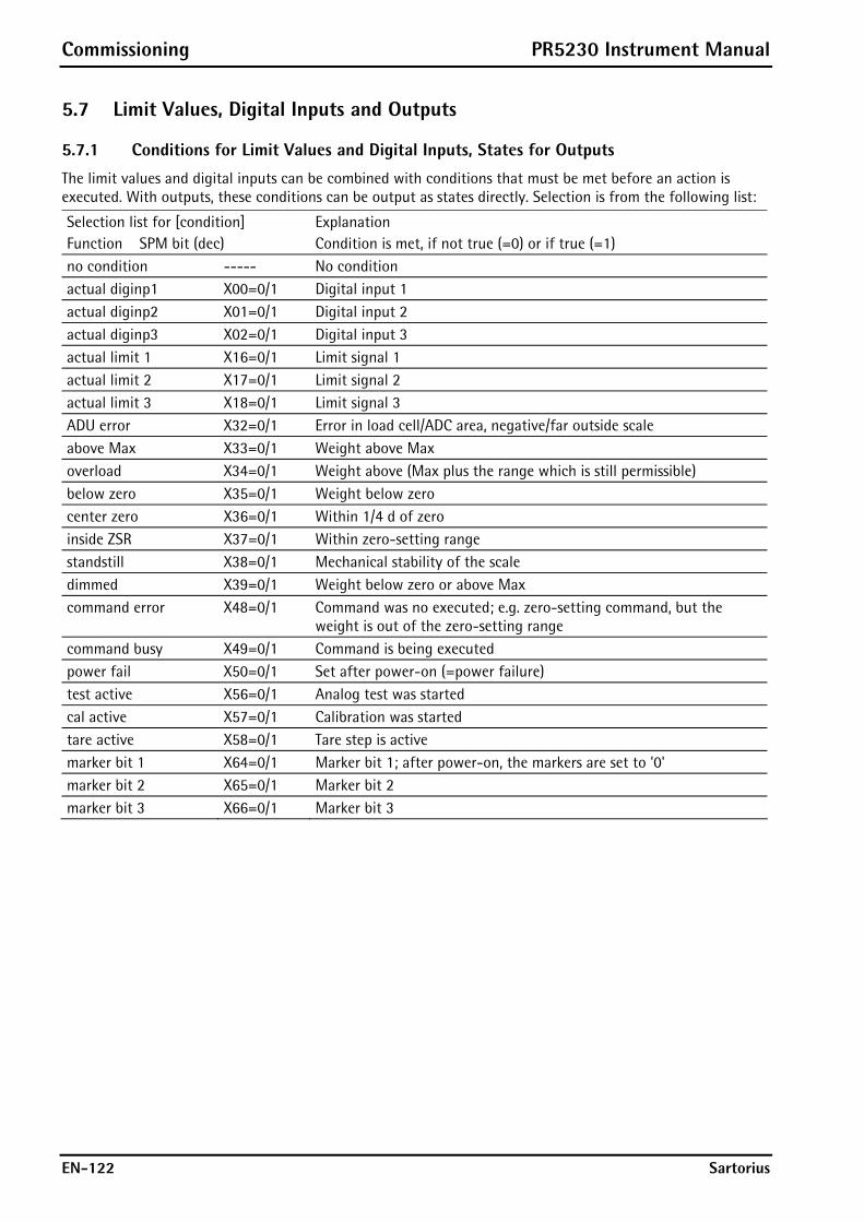
Commissioning PR5230 Instrument Manual
EN-122 Sartorius
5.7 Limit Values, Digital Inputs and Outputs
5.7.1 Conditions for Limit Values and Digital Inputs, States for Outputs
The limit values and digital inputs can be combined with conditions that must be met before an action is executed. With outputs, these conditions can be output as states directly. Selection is from the following list:
Selection list for [condition] Function SPM bit (dec)
Explanation Condition is met, if not true (=0) or if true (=1)
no condition ----- No condition actual diginp1 X00=0/1 Digital input 1 actual diginp2 X01=0/1 Digital input 2 actual diginp3 X02=0/1 Digital input 3 actual limit 1 X16=0/1 Limit signal 1 actual limit 2 X17=0/1 Limit signal 2 actual limit 3 X18=0/1 Limit signal 3 ADU error X32=0/1 Error in load cell/ADC area, negative/far outside scale above Max X33=0/1 Weight above Max overload X34=0/1 Weight above (Max plus the range which is still permissible) below zero X35=0/1 Weight below zero center zero X36=0/1 Within 1/4 d of zero inside ZSR X37=0/1 Within zero-setting range standstill X38=0/1 Mechanical stability of the scale dimmed X39=0/1 Weight below zero or above Max command error X48=0/1 Command was no executed; e.g. zero-setting command, but the
weight is out of the zero-setting range command busy X49=0/1 Command is being executed power fail X50=0/1 Set after power-on (=power failure) test active X56=0/1 Analog test was started cal active X57=0/1 Calibration was started tare active X58=0/1 Tare step is active marker bit 1 X64=0/1 Marker bit 1; after power-on, the markers are set to '0' marker bit 2 X65=0/1 Marker bit 2 marker bit 3 X66=0/1 Marker bit 3

PR5230 Instrument Manual Commissioning
Sartorius EN-123
5.7.2 Configuring Digital Inputs and Outputs
Define the digital input and output parameters under -[ Digital I/O parameter].
Press to select the specific parameter.
Press to select the respective values.
Setup/Digital I/O parameter Output 1 limit 1 out X16=0
Output 2 limit 2 out X17=1 Output 3 limit 3 out X18=1 Input 1 on set zero X112=1
Condition no condition ----- Input 1 off -no action- Input 2 on set tare X113=1
Condition no condition ----- Input 2 off -no action- Input 3 on reset tare X114=1
Condition no condition ----- Input 3 off -no action-
5.7.2.1 Configuring Outputs
Configure the required function for [Output 1] to [Output 3] by selecting a signal from the list; see Chapter 5.7.1. The output goes to the corresponding state.
Example
Setup/Digital I/O parameter
Output 1 below zero X35=0
Output 2 above MAX X33=0
Output 3 center zero X36=1
Output 1 remains true (active), as long as the weight is not below zero (X35=0). Output 2 remains true (active), as long as the weight does not exceed Max (X33=0). Output 3 becomes true (active), if the weight goes to zero ±1/4 d (X36=1).
Note: 1 = Active, if the condition is met, i.e. if the bit is set.
0 = Active, if the condition is not met.

Commissioning PR5230 Instrument Manual
EN-124 Sartorius
5.7.2.2 Configuring Inputs
An action both for signal change from 0 to 1 (on) and from 1 to 0 (off) can be determined for each of the three inputs. The action may be dependent on another condition which must be met.
Setup/Digital I/O parameter
Output 1 marker bit 1 X64=1
Output 2 marker bit 2 X65=1 Output 3 marker bit 3 X66=1 Input 1 on set tare X113=1
Condition no condition ----- Input 1 off -no action- Input 2 on -no action- Input 2 off -no action- Input 3 on -no action- Input 3 off -no action-
1. Determining an action
Determine the action for the rising edge of input 1 under [Input 1 on] from the following list (here: When the input signal changes from 0 to 1, a tare command is generated). Accordingly, an action for the falling edge can be determined.
Selection list for actions of the inputs [Input 1/2/3 on/off] Function SPM Bit -no action- ----- No function set marker 1 X64=1 Set marker 1 set marker 2 X65=1 Set marker 2 set marker 3 X66=1 Set marker 3 select net X72=1 Select net set zero X112=1 Set zero set tare X113=1 Set tare reset tare X114=1 Reset tare set test X115=1 Activate the analog test reset test X116=1 Finish the analog test reset PWF X117=1 Reset power fail set fixtare X118=1 Set fixtare (use the value in address D31 as a tare value) get fixtare X119=1 Save gross value as fixtare in address D31 set print X120=1 Activate a print order clr marker 1 X64=0 Clear marker 1 clr marker 2 X65=0 Clear marker 2 clr marker 3 X66=0 Clear marker 3 select gross X72=0 Save the gross weight in address D11
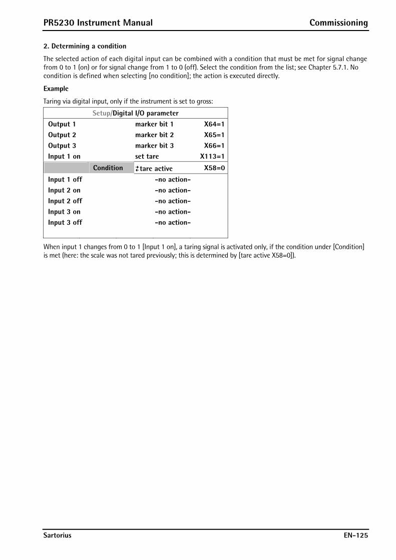
PR5230 Instrument Manual Commissioning
Sartorius EN-125
2. Determining a condition
The selected action of each digital input can be combined with a condition that must be met for signal change from 0 to 1 (on) or for signal change from 1 to 0 (off). Select the condition from the list; see Chapter 5.7.1. No condition is defined when selecting [no condition]; the action is executed directly.
Example
Taring via digital input, only if the instrument is set to gross:
Setup/Digital I/O parameter
Output 1 marker bit 1 X64=1
Output 2 marker bit 2 X65=1
Output 3 marker bit 3 X66=1
Input 1 on set tare X113=1
Condition tare active X58=0
Input 1 off -no action-
Input 2 on -no action-
Input 2 off -no action-
Input 3 on -no action-
Input 3 off -no action-
When input 1 changes from 0 to 1 [Input 1 on], a taring signal is activated only, if the condition under [Condition] is met (here: the scale was not tared previously; this is determined by [tare active X58=0]).
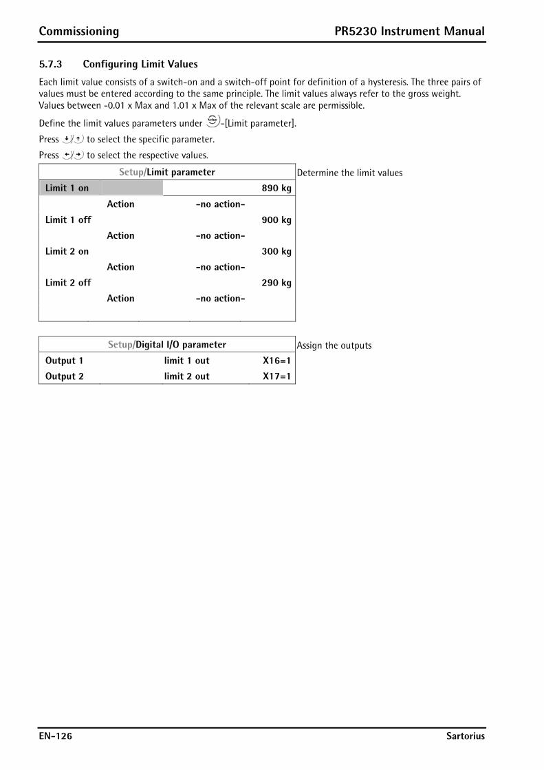
Commissioning PR5230 Instrument Manual
EN-126 Sartorius
5.7.3 Configuring Limit Values
Each limit value consists of a switch-on and a switch-off point for definition of a hysteresis. The three pairs of values must be entered according to the same principle. The limit values always refer to the gross weight. Values between -0.01 x Max and 1.01 x Max of the relevant scale are permissible.
Define the limit values parameters under -[Limit parameter].
Press to select the specific parameter.
Press to select the respective values.
Setup/Limit parameter Determine the limit values
Limit 1 on 890 kg
Action -no action- Limit 1 off 900 kg Action -no action- Limit 2 on 300 kg Action -no action- Limit 2 off 290 kg Action -no action-
Setup/Digital I/O parameter Assign the outputs
Output 1 limit 1 out X16=1 Output 2 limit 2 out X17=1
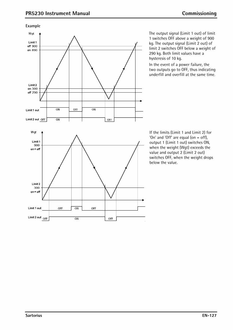
PR5230 Instrument Manual Commissioning
Sartorius EN-127
Example
The output signal (Limit 1 out) of limit 1 switches OFF above a weight of 900 kg. The output signal (Limit 2 out) of limit 2 switches OFF below a weight of 290 kg. Both limit values have a hysteresis of 10 kg. In the event of a power failure, the two outputs go to OFF, thus indicating underfill and overfill at the same time.
If the limits (Limit 1 and Limit 2) for 'On' and 'Off' are equal (on = off), output 1 (Limit 1 out) switches ON, when the weight (Wgt) exceeds the value and output 2 (Limit 2 out) switches OFF, when the weight drops below the value.
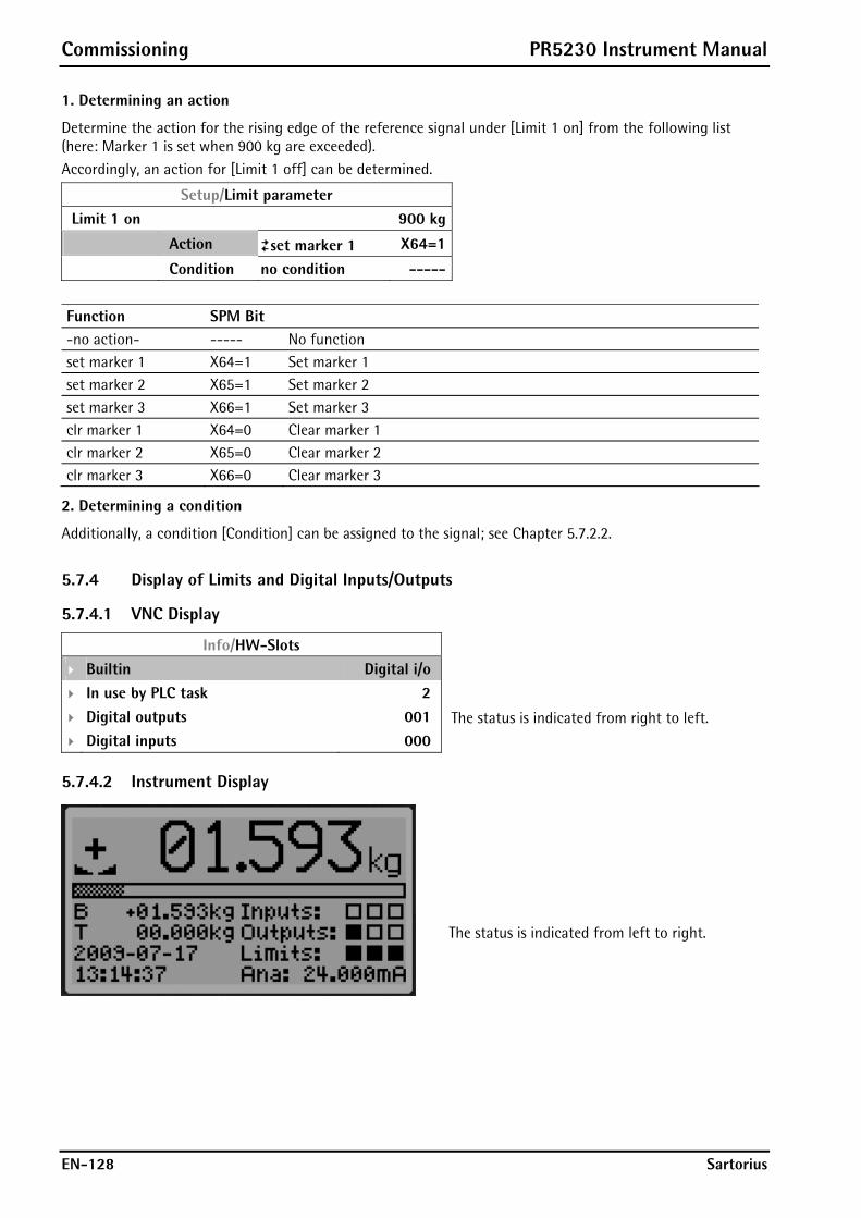
Commissioning PR5230 Instrument Manual
EN-128 Sartorius
1. Determining an action
Determine the action for the rising edge of the reference signal under [Limit 1 on] from the following list (here: Marker 1 is set when 900 kg are exceeded). Accordingly, an action for [Limit 1 off] can be determined.
Setup/Limit parameter
Limit 1 on 900 kg
Action set marker 1 X64=1
Condition no condition -----
Function SPM Bit -no action- ----- No function set marker 1 X64=1 Set marker 1 set marker 2 X65=1 Set marker 2 set marker 3 X66=1 Set marker 3 clr marker 1 X64=0 Clear marker 1 clr marker 2 X65=0 Clear marker 2 clr marker 3 X66=0 Clear marker 3
2. Determining a condition
Additionally, a condition [Condition] can be assigned to the signal; see Chapter 5.7.2.2.
5.7.4 Display of Limits and Digital Inputs/Outputs
5.7.4.1 VNC Display
Info/HW-Slots
Builtin Digital i/o
In use by PLC task 2
Digital outputs 001 The status is indicated from right to left.
Digital inputs 000
5.7.4.2 Instrument Display
The status is indicated from left to right.
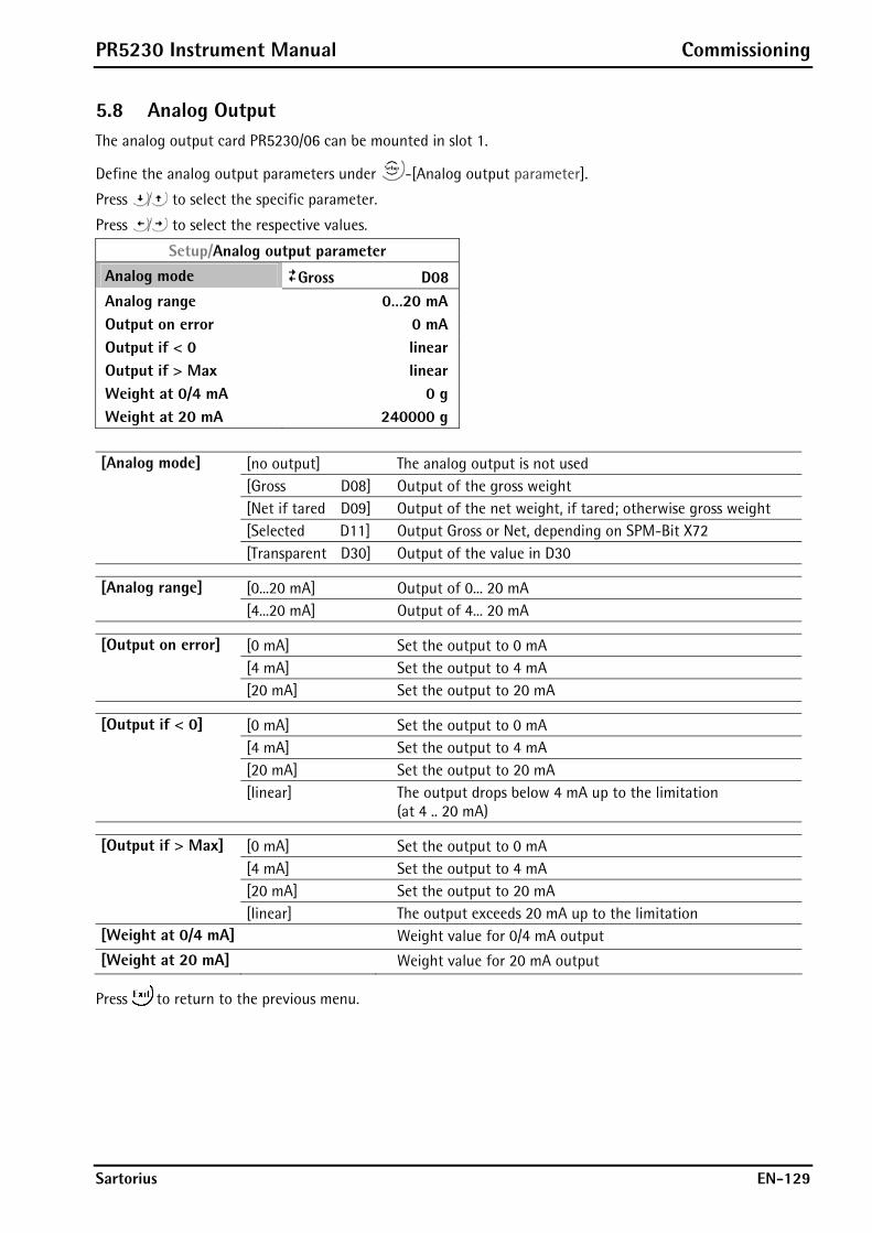
PR5230 Instrument Manual Commissioning
Sartorius EN-129
5.8 Analog Output The analog output card PR5230/06 can be mounted in slot 1.
Define the analog output parameters under -[Analog output parameter].
Press to select the specific parameter.
Press to select the respective values.
Setup/Analog output parameter
Analog mode Gross D08
Analog range 0…20 mA
Output on error 0 mA
Output if < 0 linear
Output if > Max linear
Weight at 0/4 mA 0 g
Weight at 20 mA 240000 g
[Analog mode] [no output] The analog output is not used [Gross D08] Output of the gross weight [Net if tared D09] Output of the net weight, if tared; otherwise gross weight [Selected D11] Output Gross or Net, depending on SPM-Bit X72 [Transparent D30] Output of the value in D30
[Analog range] [0...20 mA] Output of 0... 20 mA [4...20 mA] Output of 4... 20 mA
[Output on error] [0 mA] Set the output to 0 mA [4 mA] Set the output to 4 mA [20 mA] Set the output to 20 mA
[Output if < 0] [0 mA] Set the output to 0 mA [4 mA] Set the output to 4 mA [20 mA] Set the output to 20 mA [linear] The output drops below 4 mA up to the limitation
(at 4 .. 20 mA)
[Output if > Max] [0 mA] Set the output to 0 mA [4 mA] Set the output to 4 mA [20 mA] Set the output to 20 mA [linear] The output exceeds 20 mA up to the limitation [Weight at 0/4 mA] Weight value for 0/4 mA output
[Weight at 20 mA] Weight value for 20 mA output
Press to return to the previous menu.
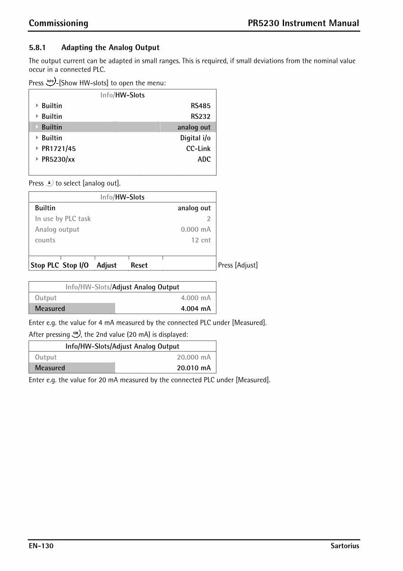
Commissioning PR5230 Instrument Manual
EN-130 Sartorius
5.8.1 Adapting the Analog Output
The output current can be adapted in small ranges. This is required, if small deviations from the nominal value occur in a connected PLC.
Press -[Show HW-slots] to open the menu:
Info/HW-Slots
Builtin RS485
Builtin RS232
Builtin analog out
Builtin Digital i/o
PR1721/45 CC-Link
PR5230/xx ADC
Press to select [analog out].
Info/HW-Slots
Builtin analog out
In use by PLC task 2
Analog output 0.000 mA
counts 12 cnt
Stop PLC Stop I/O Adjust Reset Press [Adjust]
Info/HW-Slots/Adjust Analog Output
Output 4.000 mA
Measured 4.004 mA
Enter e.g. the value for 4 mA measured by the connected PLC under [Measured].
After pressing , the 2nd value (20 mA) is displayed:
Info/HW-Slots/Adjust Analog Output
Output 20.000 mA
Measured 20.010 mA
Enter e.g. the value for 20 mA measured by the connected PLC under [Measured].
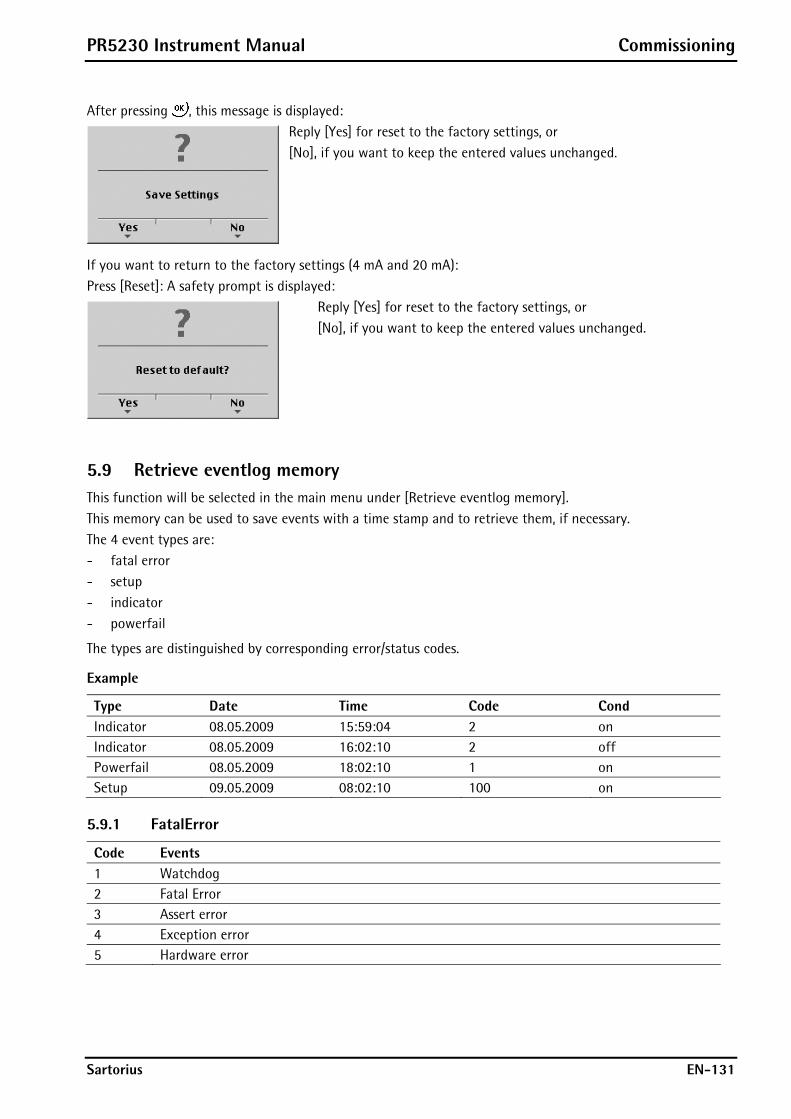
PR5230 Instrument Manual Commissioning
Sartorius EN-131
After pressing , this message is displayed:
Reply [Yes] for reset to the factory settings, or [No], if you want to keep the entered values unchanged.
If you want to return to the factory settings (4 mA and 20 mA): Press [Reset]: A safety prompt is displayed:
Reply [Yes] for reset to the factory settings, or [No], if you want to keep the entered values unchanged.
5.9 Retrieve eventlog memory This function will be selected in the main menu under [Retrieve eventlog memory]. This memory can be used to save events with a time stamp and to retrieve them, if necessary. The 4 event types are: - fatal error - setup - indicator - powerfail
The types are distinguished by corresponding error/status codes.
Example
Type Date Time Code Cond Indicator 08.05.2009 15:59:04 2 on Indicator 08.05.2009 16:02:10 2 off Powerfail 08.05.2009 18:02:10 1 on Setup 09.05.2009 08:02:10 100 on
5.9.1 FatalError
Code Events 1 Watchdog 2 Fatal Error 3 Assert error 4 Exception error 5 Hardware error

Commissioning PR5230 Instrument Manual
EN-132 Sartorius
5.9.2 Setup
This event log memory contains events, which are stored as altered data in EEPROM.
Code Events 1 Wrong PIN has been entered. 2 EEPROM has been deleted. 10 Start new adjustment. 11 Set dead load with mV/V. 12 Set span with mV/V. 13 New dead load with weight. 14 New SPAN with weight. 15 New full scale. 16 New scale interval. 17 Memory for adjustment. 18 Changes undone. 100 Serial parameters stored. 101 Change of serial interface assignment. 200 Serial assign stored. 300 Digital input/output changed. 400 Parameter limits changed. 500 Analog out parameters changed. 600 Field bus parameters changed. 700 Network parameters changed. 800 Software parameters changed. 900 Printer parameters changed. 1000 ADC parameters changed after download via HTTP. 1001 Core EEPROM changed after download via HTTP.
5.9.3 Indicator
Code Events 1 Internal arithmetic error 2 Overload 3 No valid ADC values 6 No sense input voltage 7 Negative input voltage (wrong polarity) 9 Faulty communication with ADC
5.9.4 Powerfail
Only the instrument switch-on is recorded.
5.10 Backup of EAROM This function will be selected in the main menu under [Backup of EAROM]. The configuration data of the two EAROMs can be saved for back-up on the PC and downloaded, if necessary. The content of the two EAROMs in the system can be saved for back-up on the PC and downloaded, if necessary.
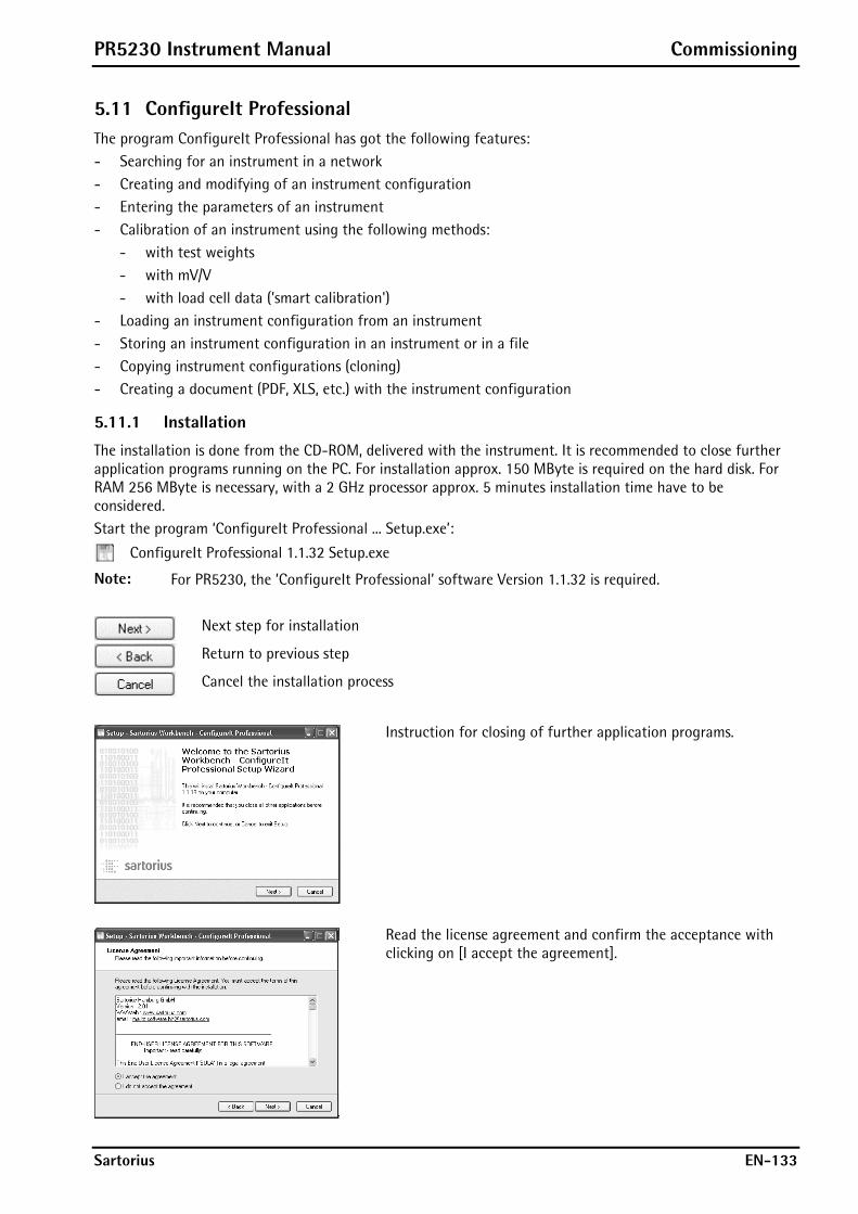
PR5230 Instrument Manual Commissioning
Sartorius EN-133
5.11 ConfigureIt Professional The program ConfigureIt Professional has got the following features: - Searching for an instrument in a network - Creating and modifying of an instrument configuration - Entering the parameters of an instrument - Calibration of an instrument using the following methods:
- with test weights - with mV/V - with load cell data ('smart calibration')
- Loading an instrument configuration from an instrument - Storing an instrument configuration in an instrument or in a file - Copying instrument configurations (cloning) - Creating a document (PDF, XLS, etc.) with the instrument configuration
5.11.1 Installation
The installation is done from the CD-ROM, delivered with the instrument. It is recommended to close further application programs running on the PC. For installation approx. 150 MByte is required on the hard disk. For RAM 256 MByte is necessary, with a 2 GHz processor approx. 5 minutes installation time have to be considered. Start the program ‘ConfigureIt Professional ... Setup.exe’:
ConfigureIt Professional 1.1.32 Setup.exe
Note: For PR5230, the ’ConfigureIt Professional’ software Version 1.1.32 is required.
Next step for installation
Return to previous step
Cancel the installation process
Instruction for closing of further application programs.
Read the license agreement and confirm the acceptance with clicking on [I accept the agreement].

Commissioning PR5230 Instrument Manual
EN-134 Sartorius
The folder where the programs and configurations are placed is shown. With [Browse] a different folder can be searched and defined.
To create an icon on the PC desktop for easy starting of the program the box has to be activated.
Continue the installation with [Install].
The progress of installation is displayed; the installation may last some minutes depending on the performance of the PC.
If the start box is activated, the ConfigureIt Professional is directly started if [Finish] is pressed.
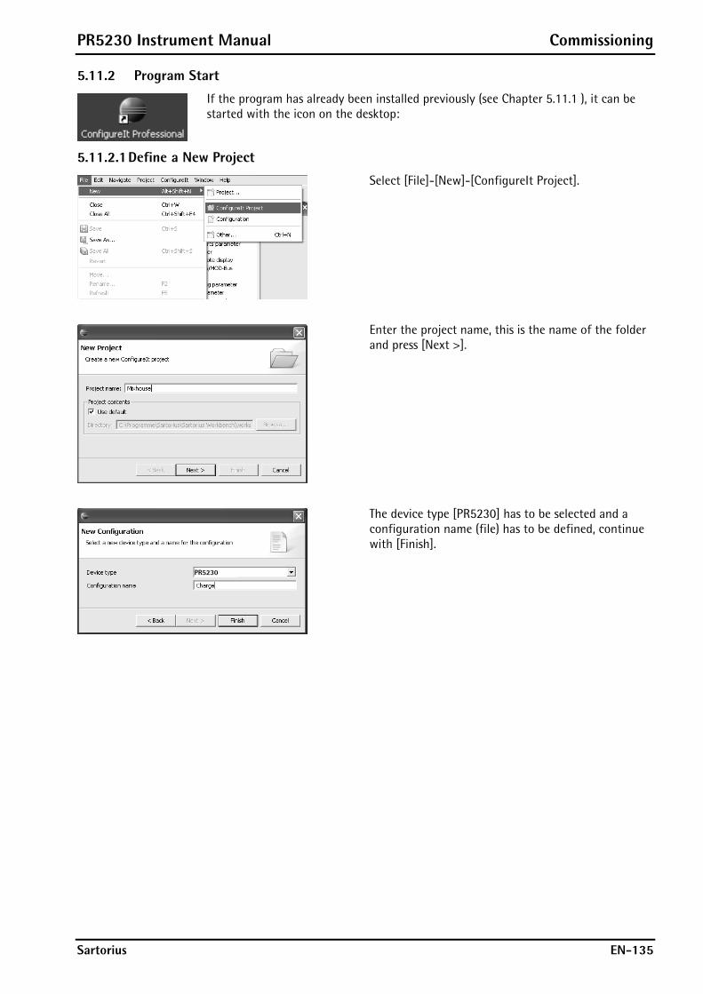
PR5230 Instrument Manual Commissioning
Sartorius EN-135
5.11.2 Program Start
If the program has already been installed previously (see Chapter 5.11.1 ), it can be started with the icon on the desktop:
5.11.2.1 Define a New Project
Select [File]-[New]-[ConfigureIt Project].
Enter the project name, this is the name of the folder and press [Next >].
The device type [PR5230] has to be selected and a configuration name (file) has to be defined, continue with [Finish].
PR5230

Commissioning PR5230 Instrument Manual
EN-136 Sartorius
5.11.2.2 Define a New Configuration
A new configuration is defined with [File]-[New]-[Configuration].
Select the instrument Type [PR5230] and continue with [Next >].
Enter or select the folder, where the configuration has to be placed and enter the name for the configuration. Continue with [Finish].
In the Navigator the new configuration [Batch.cfg] is shown in the folder [Mixhouse].
PR5230
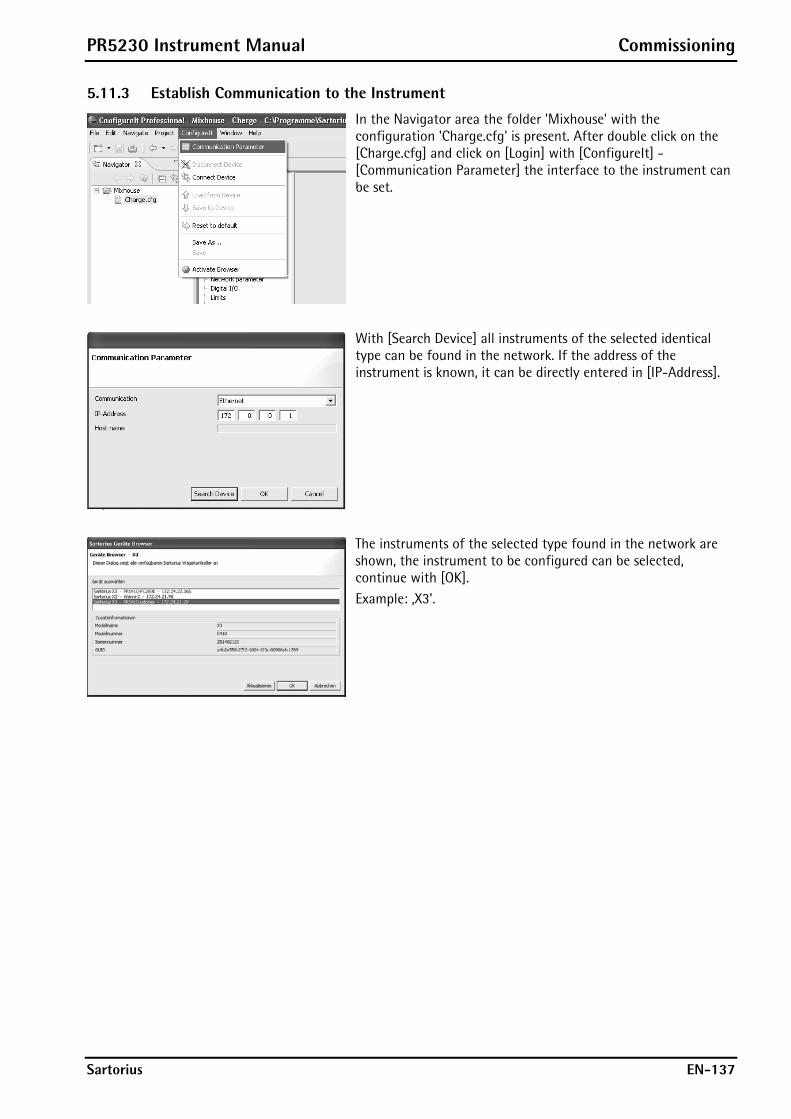
PR5230 Instrument Manual Commissioning
Sartorius EN-137
5.11.3 Establish Communication to the Instrument
In the Navigator area the folder 'Mixhouse' with the configuration 'Charge.cfg' is present. After double click on the [Charge.cfg] and click on [Login] with [ConfigureIt] -[Communication Parameter] the interface to the instrument can be set.
With [Search Device] all instruments of the selected identical type can be found in the network. If the address of the instrument is known, it can be directly entered in [IP-Address].
The instruments of the selected type found in the network are shown, the instrument to be configured can be selected, continue with [OK]. Example: ‚X3’.

Commissioning PR5230 Instrument Manual
EN-138 Sartorius
The IP-Address of the selected instrument is taken.
With [ConfigureIt]-[Connect Device] the communication to the instrument is started.
5.11.4 Transfer Dataset from Instrument to PC
With [ConfigureIt]-[Load from Device] the complete dataset (including the calibration data and parameters) is transferred from the instrument to the PC.

PR5230 Instrument Manual Commissioning
Sartorius EN-139
5.11.5 Store Current Dataset on PC
With [File]-[Save as] the complete dataset (including the calibration data and parameters) can be stored in a file.
The folder can be selected and a new name for the file can be given.
The file [Charge old.cfg] is added at [Mixhouse].
The configuration can be found on the PC with the Explorer in the following folder:

Commissioning PR5230 Instrument Manual
EN-140 Sartorius
Modification of Dataset
The configuration is selected in the Navigator, and then select e.g. [Printer]. Modifications are started by selecting [Edit parameter].
After selection of the port, where the printer of the instrument is connected, the transmission parameters can be altered. Continue with [OK].
The new parameters are shown.

PR5230 Instrument Manual Commissioning
Sartorius EN-141
With [File]-[Save As] the modified dataset can be stored in a file.
The folder can be selected and a new name for the file can be given, continue with [OK].
5.11.6 Store Current Dataset or Selected Parameters in the Instrument
With [ConfigureIT]-[Save to device] parts or the total configuration can be transferred to the instrument.
Select with [>] the parameters to be transferred or with [>>] for all parameters. The transfer is started with [OK].

Commissioning PR5230 Instrument Manual
EN-142 Sartorius
5.11.7 Reset the Instrument to Factory Default
With [ConfigureIt]-[Reset to default] the default data (data in the instrument when leaving the factory) are taken. For transfer to the instrument continue with Chapter 5.11.6 .
5.11.8 Exporting a Dataset as Printable File
With [File]-[Print] the dataset can be sent to a printer or stored in a file.
Sending the print file to a printer or selecting the data format of the dataset for storing.
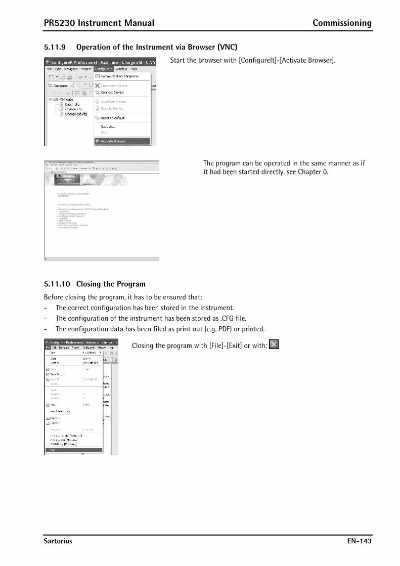
PR5230 Instrument Manual Commissioning
Sartorius EN-143
5.11.9 Operation of the Instrument via Browser (VNC)
Start the browser with [ConfigureIt]-[Activate Browser].
The program can be operated in the same manner as if it had been started directly, see Chapter 0.
5.11.10 Closing the Program
Before closing the program, it has to be ensured that: - The correct configuration has been stored in the instrument. - The configuration of the instrument has been stored as .CFG file. - The configuration data has been filed as print out (e.g. PDF) or printed.
Closing the program with [File]-[Exit] or with:

J-Bus/ModBus Protocol PR5230 Instrument Manual
EN-144 Sartorius
6 J-Bus/ModBus Protocol
6.1 General Description The J-Bus/ModBus protocol implemented in the instrument permits fast, simple and reliable communication between a PC or a PLC and up to 127 instruments. PR5230 fully supports - ModBus-RTU (via serial interface), see Chapter 6.2 - ModBus-TCP (via network interface), see Chapter 6.3 - ModBus-UDP (via network interface), see Chapter 6.3
including functions 1, 2, 3, 4, 5, 6, 8 (sub-function 0), 15 and 16. J-Bus is a French 'clone' of the ModBus. There is a small difference: J-Bus addresses count from 0 (instead of 1) to hex FFFF (instead of dec. 9999). Some ModBus masters automatically subtract 1 before sending a message, and some ModBus slaves subtract 1 to get the requested address. Thus it may happen that access to an address shifted by 1 is made; this is the only point which must be taken into account. In everyday practice, no other problems when connecting J-Bus and ModBus instruments should appear. Binary data from and to the SPM of PR5230 are transmitted using this protocol. Any data exchange includes two telegrams: a command from the PC to PR5230 and a reply from PR5230 to the PC.
Command Command PC Reply Reply PR5230
Note: A telegram sent to Slave 0 is executed by all ModBus users, but not replied by anyone! 2-byte values (16-bit values/word) have the Motorola notation. Consequence: MSB - LSB
If the received command is correct but cannot be executed nevertheless (e.g. due to a faulty address or faulty data), reply is with an error telegram.
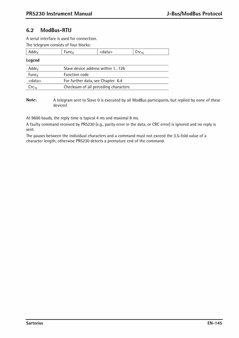
PR5230 Instrument Manual J-Bus/ModBus Protocol
Sartorius EN-145
6.2 ModBus-RTU A serial interface is used for connection. The telegram consists of four blocks:
Addr8 Func8 <data> Crc16
Legend
Addr8 Slave device address within 1…126 Func8 Function code <data> For further data, see Chapter 6.4 Crc16 Checksum of all preceding characters
Note: A telegram sent to Slave 0 is executed by all ModBus participants, but replied by none of these devices!
At 9600 bauds, the reply time is typical 4 ms and maximal 8 ms. A faulty command received by PR5230 (e.g., parity error in the data, or CRC error) is ignored and no reply is sent. The pauses between the individual characters and a command must not exceed the 3.5-fold value of a character length; otherwise PR5230 detects a premature end of the command.
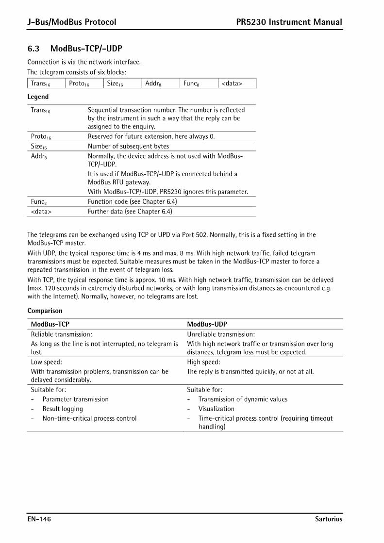
J-Bus/ModBus Protocol PR5230 Instrument Manual
EN-146 Sartorius
6.3 ModBus-TCP/-UDP Connection is via the network interface. The telegram consists of six blocks:
Trans16 Proto16 Size16 Addr8 Func8 <data>
Legend
Trans16 Sequential transaction number. The number is reflected by the instrument in such a way that the reply can be assigned to the enquiry.
Proto16 Reserved for future extension, here always 0. Size16 Number of subsequent bytes Addr8 Normally, the device address is not used with ModBus-
TCP/-UDP. It is used if ModBus-TCP/-UDP is connected behind a ModBus RTU gateway. With ModBus-TCP/-UDP, PR5230 ignores this parameter.
Func8 Function code (see Chapter 6.4) <data> Further data (see Chapter 6.4)
The telegrams can be exchanged using TCP or UPD via Port 502. Normally, this is a fixed setting in the ModBus-TCP master. With UDP, the typical response time is 4 ms and max. 8 ms. With high network traffic, failed telegram transmissions must be expected. Suitable measures must be taken in the ModBus-TCP master to force a repeated transmission in the event of telegram loss. With TCP, the typical response time is approx. 10 ms. With high network traffic, transmission can be delayed (max. 120 seconds in extremely disturbed networks, or with long transmission distances as encountered e.g. with the Internet). Normally, however, no telegrams are lost.
Comparison
ModBus-TCP ModBus-UDP Reliable transmission: As long as the line is not interrupted, no telegram is lost.
Unreliable transmission: With high network traffic or transmission over long distances, telegram loss must be expected.
Low speed: With transmission problems, transmission can be delayed considerably.
High speed: The reply is transmitted quickly, or not at all.
Suitable for: - Parameter transmission - Result logging - Non-time-critical process control
Suitable for: - Transmission of dynamic values - Visualization - Time-critical process control (requiring timeout
handling)
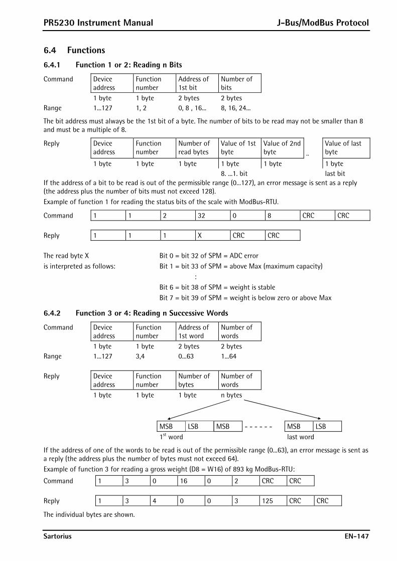
PR5230 Instrument Manual J-Bus/ModBus Protocol
Sartorius EN-147
6.4 Functions 6.4.1 Function 1 or 2: Reading n Bits
Command Device address
Function number
Address of 1st bit
Number of bits
1 byte 1 byte 2 bytes 2 bytes Range 1...127 1, 2 0, 8 , 16... 8, 16, 24...
The bit address must always be the 1st bit of a byte. The number of bits to be read may not be smaller than 8 and must be a multiple of 8.
Reply Device address
Function number
Number of read bytes
Value of 1st byte
Value of 2nd byte
..
Value of last byte
1 byte 1 byte 1 byte 1 byte 1 byte 1 byte 8. ...1. bit last bit If the address of a bit to be read is out of the permissible range (0...127), an error message is sent as a reply (the address plus the number of bits must not exceed 128). Example of function 1 for reading the status bits of the scale with ModBus-RTU.
Command 1 1 2 32 0 8 CRC CRC Reply 1 1 1 X CRC CRC The read byte X Bit 0 = bit 32 of SPM = ADC error is interpreted as follows: Bit 1 = bit 33 of SPM = above Max (maximum capacity) : Bit 6 = bit 38 of SPM = weight is stable Bit 7 = bit 39 of SPM = weight is below zero or above Max
6.4.2 Function 3 or 4: Reading n Successive Words
Command Device address
Function number
Address of 1st word
Number of words
1 byte 1 byte 2 bytes 2 bytes Range 1...127 3,4 0...63 1...64 Reply Device
address Function number
Number of bytes
Number of words
1 byte 1 byte 1 byte n bytes
MSB LSB MSB - - - - - - MSB LSB 1st word last word
If the address of one of the words to be read is out of the permissible range (0...63), an error message is sent as a reply (the address plus the number of bytes must not exceed 64). Example of function 3 for reading a gross weight (D8 = W16) of 893 kg ModBus-RTU:
Command 1 3 0 16 0 2 CRC CRC Reply 1 3 4 0 0 3 125 CRC CRC
The individual bytes are shown.
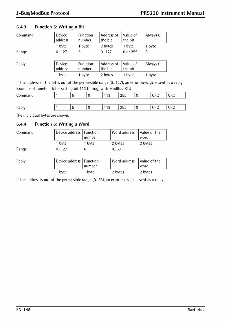
J-Bus/ModBus Protocol PR5230 Instrument Manual
EN-148 Sartorius
6.4.3 Function 5: Writing a Bit
Command Device address
Function number
Address of the bit
Value of the bit
Always 0
1 byte 1 byte 2 bytes 1 byte 1 byte Range 0...127 5 0...127 0 or 255 0
Reply Device address
Function number
Address of the bit
Value of the bit
Always 0
1 byte 1 byte 2 bytes 1 byte 1 byte
If the address of the bit is out of the permissible range (0...127), an error message is sent as a reply. Example of function 5 for setting bit 113 (taring) with ModBus-RTU:
Command 1 5 0 113 255 0 CRC CRC Reply 1 5 0 113 255 0 CRC CRC
The individual bytes are shown.
6.4.4 Function 6: Writing a Word
Command Device address Function number
Word address Value of the word
1 byte 1 byte 2 bytes 2 bytes Range 0...127 6 0...63
Reply Device address Function number
Word address Value of the word
1 byte 1 byte 2 bytes 2 bytes
If the address is out of the permissible range (0...63), an error message is sent as a reply.

PR5230 Instrument Manual J-Bus/ModBus Protocol
Sartorius EN-149
6.4.5 Function 8: Diagnosis
Command Device address Function number
Sub-function Any value
1 byte 1 byte 2 bytes 2 bytes Range 1...127 8 0
This function is intended for testing the communication. Only sub-function 0 is supported. The received command is sent as a reply.
Command Device address Function number
Sub-function Value of the command
1 byte 1 byte 2 bytes 2 bytes
6.4.6 Function 15: Writing n Successive Bits
Command Device address
Function number
Address of the 1st bit
Number of bits
Number of bytes
Value of bits
1 byte 1 byte 2 bytes 2 bytes 1 byte n bytes Range 0...127 15 0...127 8,16, 24 1,2,3...
1st byte 2nd byte 3rd byte - - - - - - - - - - last byte 8th ... 1st bit last bit
The bit address must always be the 1st bit of a byte. The number of bits to be read must not be smaller than 8 and must be a multiple of 8. The address plus the number of bits must not exceed 128. Example of function 15 with ModBus-RTU:
Command 1 15 0 64 0 8 1 3 CRC CRC Reply 1 15 0 64 0 8 CRC CRC
The individual bytes are shown.

J-Bus/ModBus Protocol PR5230 Instrument Manual
EN-150 Sartorius
6.4.7 Function 16: Writing n Successive Words
Command Device address
Function number
Address of 1st word
Number of words
Number of bytes
Value of words
1 byte 1 byte 2 bytes 2 bytes 1 byte n bytes Range 0...127 16 0...63 1...64 2...128
MSB LSB MSB - - - - - - MSB LSB 1st word last word
Reply Device address Function number
Address of 1st word
Number of words
1 byte 1 byte 2 bytes 2 bytes
If the address is out of the permissible range (0...63), an error message is sent as a reply (the address plus the number of bytes must not exceed 64). Example of function 16 for writing the limit_1 switch-on point using value 893 with ModBus-RTU:
Command 1 16 0 48 0 2 4 0 0 3 125 CRC CRC Reply 1 16 0 48 0 2 CRC CRC
The individual bytes are shown.
6.5 Error Messages If a command was transmitted correctly, but cannot be executed because e.g. the address is too high, an error message is sent as a reply to the command. The error message has the following format:
Device address Function number +128 Error number CRC 16 1 byte 1 byte 1 byte 2 bytes
The 2nd byte contains the received function number; the most significant bit is set additionally. Meaning of the error number:
1 The function number is unknown 2 The address is out of the permissible range 3 The data format is faulty (e.g. more data than specified in the number were written)
Example of an error message, which was generated by an invalid function number with ModBus-RTU.
Command 1 9 0 0 0 0 CRC CRC Reply 1 137 1 CRC CRC
The individual bytes are shown.

PR5230 Instrument Manual J-Bus/ModBus Protocol
Sartorius EN-151
6.6 Word Addresses
16 Gross weight, 1st byte (MSB) Gross weight, 2nd byte
17 Gross weight, 3rd byte Gross weight, 4th byte (LSB)
2 32 33 34 35 36 37 38 39 40 41 42 43 44 45 46 47
7 112 113 114 115 116 117 118 119 120 121 122 123 124 125 126 127
Address Description Read bits: 32 ADC error 33 Above Max (full scale deflection) 34 Above Max + n d 35 Below zero (minus sign) 36 Zero within ¼ d 37 Within zero setting range 38 The weight is stable 39 The weight is below zero or above Max Write bits: 112 Set zero 1130 Set tare 114 Reset tare
For further bits, see Chapter 10.
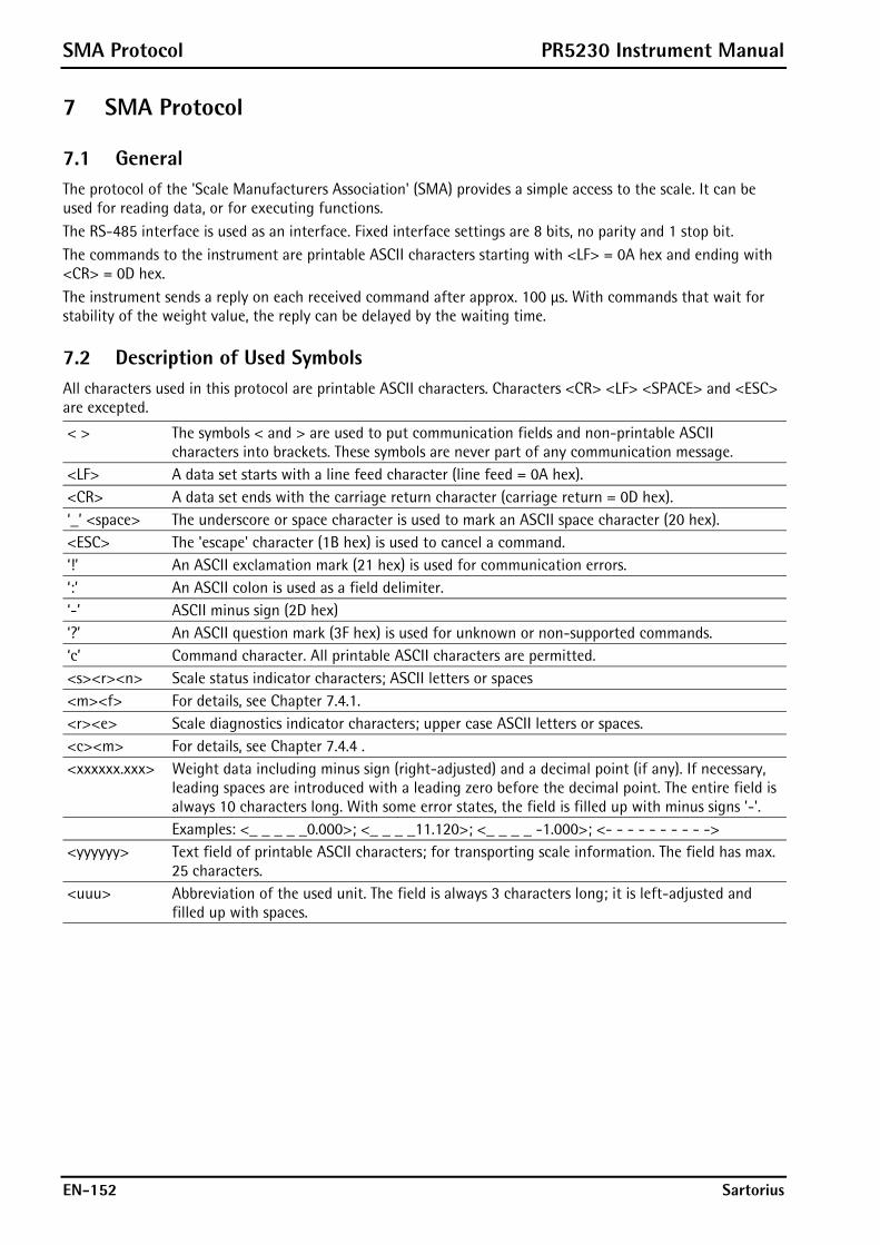
SMA Protocol PR5230 Instrument Manual
EN-152 Sartorius
7 SMA Protocol
7.1 General The protocol of the 'Scale Manufacturers Association' (SMA) provides a simple access to the scale. It can be used for reading data, or for executing functions. The RS-485 interface is used as an interface. Fixed interface settings are 8 bits, no parity and 1 stop bit. The commands to the instrument are printable ASCII characters starting with <LF> = 0A hex and ending with <CR> = 0D hex. The instrument sends a reply on each received command after approx. 100 μs. With commands that wait for stability of the weight value, the reply can be delayed by the waiting time.
7.2 Description of Used Symbols All characters used in this protocol are printable ASCII characters. Characters <CR> <LF> <SPACE> and <ESC> are excepted.
< > The symbols < and > are used to put communication fields and non-printable ASCII characters into brackets. These symbols are never part of any communication message.
<LF> A data set starts with a line feed character (line feed = 0A hex). <CR> A data set ends with the carriage return character (carriage return = 0D hex). ‘_’ <space> The underscore or space character is used to mark an ASCII space character (20 hex). <ESC> The 'escape' character (1B hex) is used to cancel a command. ‘!’ An ASCII exclamation mark (21 hex) is used for communication errors. ‘:’ An ASCII colon is used as a field delimiter. ‘-’ ASCII minus sign (2D hex) ‘?’ An ASCII question mark (3F hex) is used for unknown or non-supported commands. ‘c’ Command character. All printable ASCII characters are permitted. <s><r><n> Scale status indicator characters; ASCII letters or spaces <m><f> For details, see Chapter 7.4.1. <r><e> Scale diagnostics indicator characters; upper case ASCII letters or spaces. <c><m> For details, see Chapter 7.4.4 . <xxxxxx.xxx> Weight data including minus sign (right-adjusted) and a decimal point (if any). If necessary,
leading spaces are introduced with a leading zero before the decimal point. The entire field is always 10 characters long. With some error states, the field is filled up with minus signs '-'.
Examples: <_ _ _ _ _0.000>; <_ _ _ _11.120>; <_ _ _ _ -1.000>; <- - - - - - - - - -> <yyyyyy> Text field of printable ASCII characters; for transporting scale information. The field has max.
25 characters. <uuu> Abbreviation of the used unit. The field is always 3 characters long; it is left-adjusted and
filled up with spaces.
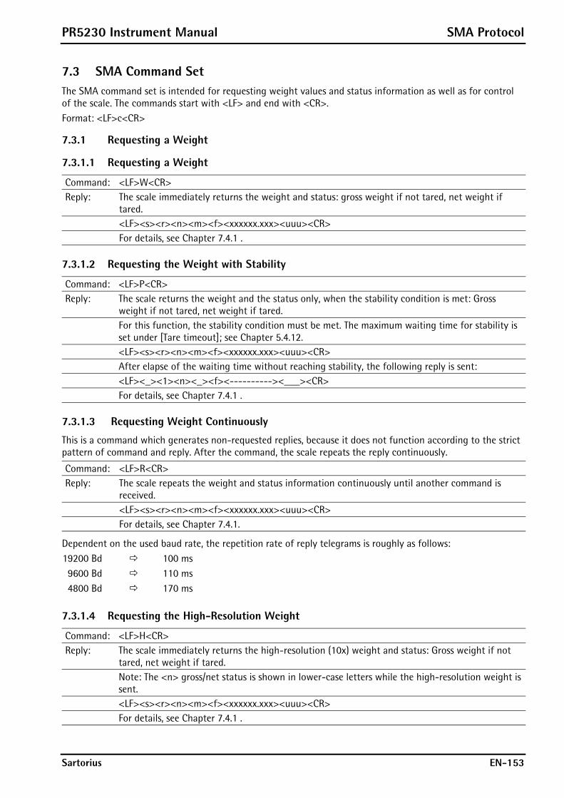
PR5230 Instrument Manual SMA Protocol
Sartorius EN-153
7.3 SMA Command Set The SMA command set is intended for requesting weight values and status information as well as for control of the scale. The commands start with <LF> and end with <CR>. Format: <LF>c<CR>
7.3.1 Requesting a Weight
7.3.1.1 Requesting a Weight
Command: <LF>W<CR> Reply: The scale immediately returns the weight and status: gross weight if not tared, net weight if
tared. <LF><s><r><n><m><f><xxxxxx.xxx><uuu><CR> For details, see Chapter 7.4.1 .
7.3.1.2 Requesting the Weight with Stability
Command: <LF>P<CR> Reply: The scale returns the weight and the status only, when the stability condition is met: Gross
weight if not tared, net weight if tared. For this function, the stability condition must be met. The maximum waiting time for stability is
set under [Tare timeout]; see Chapter 5.4.12. <LF><s><r><n><m><f><xxxxxx.xxx><uuu><CR> After elapse of the waiting time without reaching stability, the following reply is sent: <LF><_><1><n><_><f><----------><___><CR> For details, see Chapter 7.4.1 .
7.3.1.3 Requesting Weight Continuously
This is a command which generates non-requested replies, because it does not function according to the strict pattern of command and reply. After the command, the scale repeats the reply continuously.
Command: <LF>R<CR> Reply: The scale repeats the weight and status information continuously until another command is
received. <LF><s><r><n><m><f><xxxxxx.xxx><uuu><CR> For details, see Chapter 7.4.1.
Dependent on the used baud rate, the repetition rate of reply telegrams is roughly as follows: 19200 Bd 100 ms 9600 Bd 110 ms 4800 Bd 170 ms
7.3.1.4 Requesting the High-Resolution Weight
Command: <LF>H<CR> Reply: The scale immediately returns the high-resolution (10x) weight and status: Gross weight if not
tared, net weight if tared. Note: The <n> gross/net status is shown in lower-case letters while the high-resolution weight is
sent. <LF><s><r><n><m><f><xxxxxx.xxx><uuu><CR> For details, see Chapter 7.4.1 .

SMA Protocol PR5230 Instrument Manual
EN-154 Sartorius
7.3.1.5 Requesting the High-Resolution Weight with Stability
Command: <LF>Q<CR> Reply: The scale returns the weight and status only, when the stability condition is met: Gross weight if
not tared, net weight if tared. The stability condition must be met for this function. The maximum waiting time for stability is
set under [Tare timeout]; see Chapter 5.4.12. <LF><s><r><n><m><f><xxxxxx.xxx><uuu><CR> After elapse of the waiting time without reaching stability, the following reply is sent: <LF><_><1><n><_><f><----------><___><CR> For details, see Chapter 7.4.1.
7.3.1.6 Requesting the High-Resolution Weight Continuously
This is a command which generates non-requested replies, because it does not function according to the strict command-and-reply pattern. After the command, the scale repeats the reply continuously.
Command: <LF>S<CR> Reply: The scale repeats the high-resolution weight and status information continuously, until another
command is received. <LF><s><r><n><m><f><xxxxxx.xxx><uuu><CR> For details, see Chapter 7.4.1 .
Dependent on the used baud rate, the repetition rate of reply telegrams is roughly as follows: 19200 Bd 100 ms 9600 Bd 110 ms 4800 Bd 170 ms
7.3.1.7 Requesting the Tare Weight
Command: <LF>M<CR> Reply: The scale returns the tare weight and signals the 'tared' status in the <n> status character. <LF><s><r><T><m><f><xxxxxx.xxx><uuu><CR> For details, see Chapter 7.4.1.
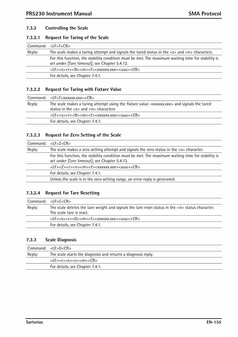
PR5230 Instrument Manual SMA Protocol
Sartorius EN-155
7.3.2 Controlling the Scale
7.3.2.1 Request for Taring of the Scale
Command: <LF>T<CR> Reply: The scale makes a taring attempt and signals the tared status in the <s> and <n> characters. For this function, the stability condition must be met. The maximum waiting time for stability is
set under [Tare timeout]; see Chapter 5.4.12. <LF><s><r><N><m><f><xxxxxx.xxx><uuu><CR> For details, see Chapter 7.4.1.
7.3.2.2 Request for Taring with Fixtare Value
Command: <LF>T<xxxxxx.xxx><CR> Reply: The scale makes a taring attempt using the fixtare value <xxxxxx.xxx> and signals the tared
status in the <s> and <n> characters <LF><s><r><N><m><f><xxxxxx.xxx><uuu><CR> For details, see Chapter 7.4.1.
7.3.2.3 Request for Zero Setting of the Scale
Command: <LF>Z<CR> Reply: The scale makes a zero setting attempt and signals the zero status in the <s> character. For this function, the stability condition must be met. The maximum waiting time for stability is
set under [Tare timeout]; see Chapter 5.4.12. <LF><Z><r><n><m><f><xxxxxx.xxx><uuu><CR> For details, see Chapter 7.4.1. Unless the scale is in the zero setting range, an error reply is generated.
7.3.2.4 Request for Tare Resetting
Command: <LF>C<CR> Reply: The scale deletes the tare weight and signals the tare reset status in the <n> status character.
The scale tare is reset. <LF><s><r><G><m><f><xxxxxx.xxx><uuu><CR> For details, see Chapter 7.4.1.
7.3.3 Scale Diagnosis
Command: <LF>D<CR> Reply: The scale starts the diagnosis and returns a diagnosis reply. <LF><r><e><c><m><CR> For details, see Chapter 7.4.1.
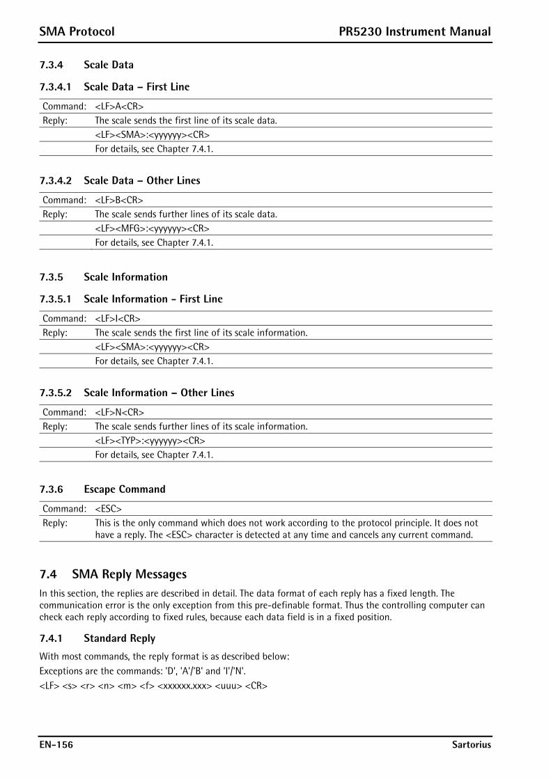
SMA Protocol PR5230 Instrument Manual
EN-156 Sartorius
7.3.4 Scale Data
7.3.4.1 Scale Data – First Line
Command: <LF>A<CR> Reply: The scale sends the first line of its scale data. <LF><SMA>:<yyyyyy><CR> For details, see Chapter 7.4.1.
7.3.4.2 Scale Data – Other Lines
Command: <LF>B<CR> Reply: The scale sends further lines of its scale data. <LF><MFG>:<yyyyyy><CR> For details, see Chapter 7.4.1.
7.3.5 Scale Information
7.3.5.1 Scale Information - First Line
Command: <LF>I<CR> Reply: The scale sends the first line of its scale information. <LF><SMA>:<yyyyyy><CR> For details, see Chapter 7.4.1.
7.3.5.2 Scale Information – Other Lines
Command: <LF>N<CR> Reply: The scale sends further lines of its scale information. <LF><TYP>:<yyyyyy><CR> For details, see Chapter 7.4.1.
7.3.6 Escape Command
Command: <ESC> Reply: This is the only command which does not work according to the protocol principle. It does not
have a reply. The <ESC> character is detected at any time and cancels any current command.
7.4 SMA Reply Messages In this section, the replies are described in detail. The data format of each reply has a fixed length. The communication error is the only exception from this pre-definable format. Thus the controlling computer can check each reply according to fixed rules, because each data field is in a fixed position.
7.4.1 Standard Reply
With most commands, the reply format is as described below: Exceptions are the commands: 'D', 'A'/'B' and 'I'/'N'. <LF> <s> <r> <n> <m> <f> <xxxxxx.xxx> <uuu> <CR>
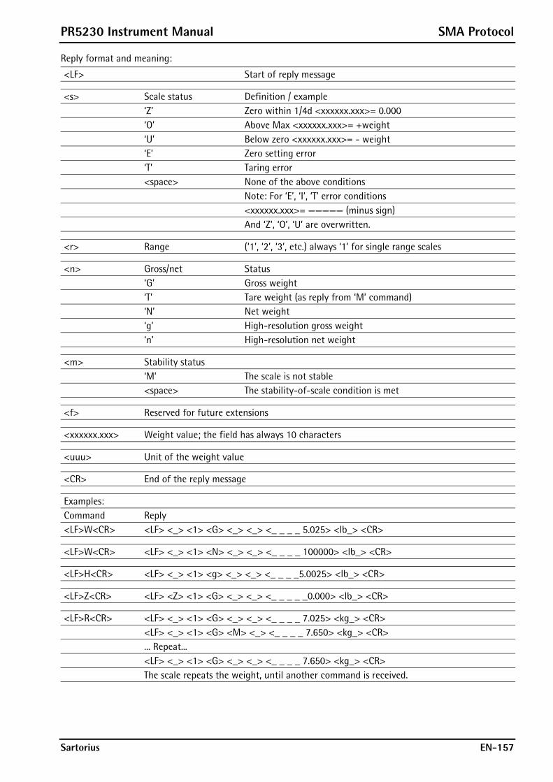
PR5230 Instrument Manual SMA Protocol
Sartorius EN-157
Reply format and meaning:
<LF> Start of reply message
<s> Scale status Definition / example ‘Z’ Zero within 1/4d <xxxxxx.xxx>= 0.000 ‘O’ Above Max <xxxxxx.xxx>= +weight ‘U’ Below zero <xxxxxx.xxx>= - weight ‘E’ Zero setting error ‘T’ Taring error <space> None of the above conditions Note: For ‘E’, ‘I’, ‘T’ error conditions <xxxxxx.xxx>= ————— (minus sign) And ‘Z’, ‘O’, ‘U’ are overwritten.
<r> Range (‘1’, ‘2’, ‘3’, etc.) always ‘1’ for single range scales
<n> Gross/net Status ‘G’ Gross weight ‘T’ Tare weight (as reply from ‘M’ command) ‘N’ Net weight ‘g’ High-resolution gross weight ‘n’ High-resolution net weight
<m> Stability status ‘M’ The scale is not stable <space> The stability-of-scale condition is met
<f> Reserved for future extensions
<xxxxxx.xxx> Weight value; the field has always 10 characters
<uuu> Unit of the weight value
<CR> End of the reply message
Examples: Command Reply <LF>W<CR> <LF> <_> <1> <G> <_> <_> <_ _ _ _ 5.025> <lb_> <CR>
<LF>W<CR> <LF> <_> <1> <N> <_> <_> <_ _ _ _ 100000> <lb_> <CR>
<LF>H<CR> <LF> <_> <1> <g> <_> <_> <_ _ _ _5.0025> <lb_> <CR>
<LF>Z<CR> <LF> <Z> <1> <G> <_> <_> <_ _ _ _ _0.000> <lb_> <CR>
<LF>R<CR> <LF> <_> <1> <G> <_> <_> <_ _ _ _ 7.025> <kg_> <CR> <LF> <_> <1> <G> <M> <_> <_ _ _ _ 7.650> <kg_> <CR> ... Repeat... <LF> <_> <1> <G> <_> <_> <_ _ _ _ 7.650> <kg_> <CR> The scale repeats the weight, until another command is received.
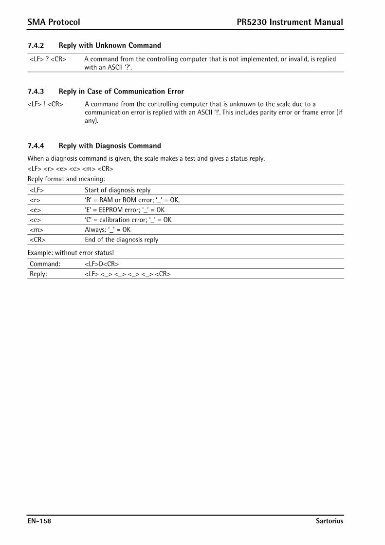
SMA Protocol PR5230 Instrument Manual
EN-158 Sartorius
7.4.2 Reply with Unknown Command
<LF> ? <CR> A command from the controlling computer that is not implemented, or invalid, is replied with an ASCII ‘?’.
7.4.3 Reply in Case of Communication Error
<LF> ! <CR> A command from the controlling computer that is unknown to the scale due to a communication error is replied with an ASCII ‘!’. This includes parity error or frame error (if any).
7.4.4 Reply with Diagnosis Command
When a diagnosis command is given, the scale makes a test and gives a status reply. <LF> <r> <e> <c> <m> <CR> Reply format and meaning:
<LF> Start of diagnosis reply <r> ‘R’ = RAM or ROM error; ‘_’ = OK, <e> ‘E’ = EEPROM error; ‘_’ = OK <c> ‘C’ = calibration error; ‘_’ = OK <m> Always: ‘_’ = OK <CR> End of the diagnosis reply
Example: without error status!
Command: <LF>D<CR> Reply: <LF> <_> <_> <_> <_> <CR>
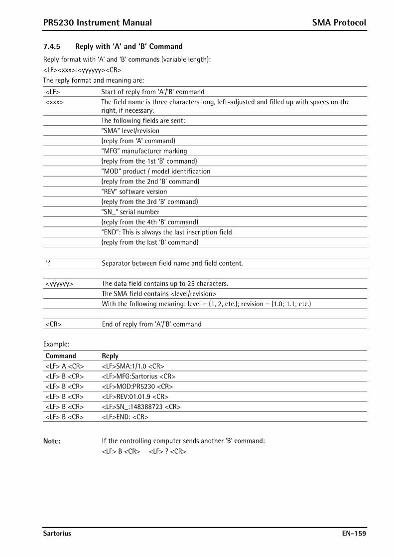
PR5230 Instrument Manual SMA Protocol
Sartorius EN-159
7.4.5 Reply with ‘A’ and ‘B’ Command
Reply format with ‘A' and 'B' commands (variable length): <LF><xxx>:<yyyyyy><CR> The reply format and meaning are:
<LF> Start of reply from 'A'/'B' command <xxx> The field name is three characters long, left-adjusted and filled up with spaces on the
right, if necessary. The following fields are sent: “SMA” level/revision (reply from ‘A’ command) “MFG” manufacturer marking (reply from the 1st ‘B’ command) “MOD” product / model identification (reply from the 2nd ‘B’ command) “REV” software version (reply from the 3rd ‘B’ command) “SN_“ serial number (reply from the 4th ‘B’ command) “END”: This is always the last inscription field (reply from the last ‘B’ command)
‘:’ Separator between field name and field content. <yyyyyy> The data field contains up to 25 characters. The SMA field contains <level/revision> With the following meaning: level = (1, 2, etc.); revision = (1.0; 1.1; etc.) <CR> End of reply from 'A'/'B' command
Example:
Command Reply <LF> A <CR> <LF>SMA:1/1.0 <CR> <LF> B <CR> <LF>MFG:Sartorius <CR> <LF> B <CR> <LF>MOD:PR5230 <CR> <LF> B <CR> <LF>REV:01.01.9 <CR> <LF> B <CR> <LF>SN_:148388723 <CR> <LF> B <CR> <LF>END: <CR>
Note: If the controlling computer sends another 'B' command: <LF> B <CR> <LF> ? <CR>

SMA Protocol PR5230 Instrument Manual
EN-160 Sartorius
7.4.6 Scale Reply with ‘I’ and ‘N’ Commands
Reply format with ‘I' and 'N' commands (variable length): <LF><xxx>:<yyyyyy><CR> Reply format and meaning:
<LF> Start of reply from 'I'/'N' command
<xxx> The field name is three characters long, left-adjusted and filled up with spaces, if necessary. The following fields are sent: “SMA” level/revision (reply from ‘I’ command) “TYP” Scale type: ‘S’= scale (reply from the 1st ‘N” command) “CAP” Max, unit, scale interval and decimal position, separated by ‘:’ Meaning: yyyyyy= uuu:c..c:n:d uuu= unit n= scale interval (e.g. 1, 2, 5,10,20…) without decimal point d= decimal point position ‘0’= without, ‘1’= xxxx.x, ‘2’= xxx.xx, ‘3’= xx.xxx , ... etc. (reply from the 2nd ‘N’ command) “CMD” Supported SMA commands (reply from the 3rd ‘N’ command) “END” This is always the last inscription field (reply from the last ‘N’ command) ‘:’ Separator between field name and field content.
<yyyyyy> The data field contains up to 25 characters. The SMA field contains <level/revision> Meaning: level = (1, 2, etc.); revision = (1.0, 1.1, etc.)
<CR> End of reply from 'I'/'N' command
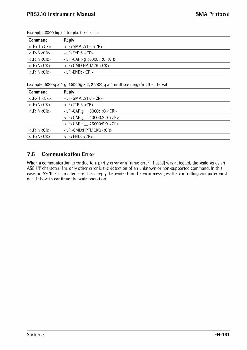
PR5230 Instrument Manual SMA Protocol
Sartorius EN-161
Example: 6000 kg x 1 kg platform scale
Command Reply <LF> I <CR> <LF>SMA:2/1.0 <CR> <LF>N<CR> <LF>TYP:S <CR> <LF>N<CR> <LF>CAP:kg_:6000:1:0 <CR> <LF>N<CR> <LF>CMD:HPTMCR <CR> <LF>N<CR> <LF>END: <CR>
Example: 5000g x 1 g, 10000g x 2, 25000 g x 5 multiple range/multi-interval
Command Reply <LF> I <CR> <LF>SMA:2/1.0 <CR> <LF>N<CR> <LF>TYP:S <CR> <LF>N<CR> <LF>CAP:g__:5000:1:0 <CR> <LF>CAP:g__:10000:2:0 <CR> <LF>CAP:g__:25000:5:0 <CR> <LF>N<CR> <LF>CMD:HPTMCRQ <CR> <LF>N<CR> <LF>END: <CR>
7.5 Communication Error When a communication error due to a parity error or a frame error (if used) was detected, the scale sends an ASCII ‘!’ character. The only other error is the detection of an unknown or non-supported command. In this case, an ASCII '?' character is sent as a reply. Dependent on the error messages, the controlling computer must decide how to continue the scale operation.
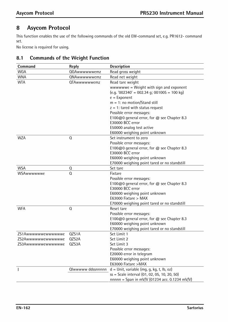
Asycom Protocol PR5230 Instrument Manual
EN-162 Sartorius
8 Asycom Protocol This function enables the use of the following commands of the old EW-command set, e.g. PR1612- command set. No license is required for using.
8.1 Commands of the Weight Function Command Reply Description WGA QGAwwwwwwemz Read gross weight WNA QNAwwwwwwemz Read net weight WTA QTAwwwwwwemz Read tare weight wwwwwwe = Weight with sign and exponent
(e.g. '002340' = 002.34 g; 001005 = 100 kg) e = Exponent m = 1: no motion/Stand still z = 1: tared with status request
Possible error messages: E100@0 general error, for @ see Chapter 8.3 E30000 BCC error E50000 analog test active E60000 weighing point unknown
WZA Q Set instrument to zero Possible error messages:
E100@0 general error, for @ see Chapter 8.3 E30000 BCC error E60000 weighing point unknown E70000 weighing point tared or no standstill
WSA Q Set tare WSAwwwwwwe Q Fixtare Possible error messages:
E100@0 general error, for @ see Chapter 8.3 E30000 BCC error E60000 weighing point unknown E63000 Fixtare > MAX E70000 weighing point tared or no standstill
WFA Q Reset tare Possible error messages:
E100@0 general error, for @ see Chapter 8.3 E60000 weighing point unknown E70000 weighing point tared or no standstill
ZS1Awwwwwwewwwwwwe QZS1A Set Limit 1 ZS2Awwwwwwewwwwwwe QZS2A Set Limit 2 ZS3Awwwwwwewwwwwwe QZS3A Set Limit 3 Possible error messages:
E20000 error in telegram E60000 weighing point unknown E63000 Fixtare >MAX
I QIwwwww ddssnnnnn
d = Unit, variable (mg, g, kg, t, lb, oz) ss = Scale interval (01, 02, 05, 10, 20, 50) nnnnn = Span in mV/V (01234 acc. 0.1234 mV/V)

PR5230 Instrument Manual Asycom Protocol
Sartorius EN-163
8.2 Other Commands
Command Reply Description ZSDTTMMJJJJssmm QZSD Set date and time Possible error messages:
E20000 telegram too long E60000 telegram too short
ZSC QZSC Reset communication V QV5230-1.00 Version request LV QLVxxxx/xx-
x.xxaaaaaa dssnnnnnttttt
xxxx/xx-x.xx = instrument version aaaaaa = Max in 5 digits with dec. point d = Unit, variable (mg, g, kg, t, lb, oz) ss = Scale interval (01, 02, 05, 10, 20, 50) nnnnn = Span in mV/V (e.g. 01234 acc. to 0.1234 mV/V) ttttt = deadload in mV/V
(e.g. 00234 acc. to 0.0234 mV/V)
8.3 SPM Commands
Command Reply Description mrx<aa><aa> qmrx<0q> Read SPM bit mrb<aa><aa> qmrb<dd> Read SPM byte mrw<aa><aa> qmrw<dd><dd> Read SPM word mrd<aa><aa> qmrd<dd<dd><dd><dd> Read SPM double word mrb<aa><aa><nn> qmrb<dd> Read SPM bytes mrw<aa><aa><nn> qmrw<dd> Read SPM words mrd<aa><aa><nn> qmrd<dd> Read SPM double words Length 1 can be omitted. msx<aa><aa> q Set bit mcx<aa><aa> q Clear bit msb<aa><aa> q Set byte mcb<aa><aa> q Clear byte msw<aa><aa> q Set word mcw<aa><aa> q Clear word msd<aa><aa> q Set double word mcd<aa><aa> q Clear double word mwx<aa><aa><0q> q Write SPM bit mwb<aa><aa><dd> q Write SPM byte mww<aa><aa><dd><dd> q Write SPM word mwd<aa><aa><dd><dd><dd><dd> q Write SPM D word mwb<aa><aa><nn><dd> q Write nn SPM bytes mww<aa><aa><nn><dd><dd> q Write nn SPM words mwd<aa><aa><nn><dd><dd><dd><dd> q Write nn SPM D words Length 1 can be omitted. An AND/OR function is also possible.

Asycom Protocol PR5230 Instrument Manual
EN-164 Sartorius
Legend
(<aa> a character in binary code) m Memory command, binary r,w,a,o,s,c Read, write, AND, OR, set, clear x,b,w,d Bit, byte, word, double word q Quit <aa><aa> Address (high byte, low byte) <dd> Data byte <nn> Number of data <0q> 1 bit <dd> Several data bytes
In case of error, the reply is e<xx><yy><zz>, see also Chapter 8.4.
Note: The addresses in these telegrams are binary. Die addresses in the list of Chapter 9 are decimal.
8.4 Error Messages for Asycom Commands
Error Description Error Description E20000 Error in telegram structure E10010 Arithmetic overflow E30000 BCC error E10020 Overload E40000 Hardware error messages E10030 ADC hardware error E50000 Analog test active E10040 weight > 5 digits E60000 Wrong address/weighing point E10050 No weight E63000 Fixtare > MAX E10060 No Sense voltage E70000 Tared weighing point or no standstill E10070 Exchanged inputs

PR5230 Instrument Manual Fieldbus Interface
Sartorius EN-165
9 Fieldbus Interface
9.1 Fieldbus Interface Protocol The interface works with an 8-byte write window and an 8-byte read window. The fieldbus exchanges its data cyclically with each slave. This means: In each cycle, 8 bytes are written and 8 bytes are read, also if the data content is unchanged. The fieldbus protocol ensures the data transport between the fieldbus master and the 2 x 8-byte data windows. The interface protocol runs under the fieldbus and manages the access to a multitude of different data.
Fieldbus Interface
Data and Functions with PR5230
- Weight data - Weight status - Limit values - Digital inputs - Digital outputs - Analog output
8-Byte Write Window
8-Byte Read Window
Interfaceprotocol
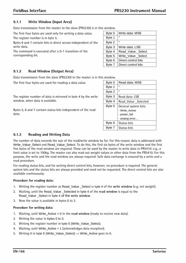
Fieldbus Interface PR5230 Instrument Manual
EN-166 Sartorius
9.1.1 Write Window (Input Area)
Data transmission from the master to the slave (PR5230) is in this window.
Byte 0 Write data: MSB Byte 1 " Byte 2 " Byte 3 Write data: LSB Byte 4 Read_Value _Select Byte 5 Write_Value _Select Byte 6 Direct control bits
The first four bytes are used only for writing a data value. The register number is in byte 5. Bytes 6 and 7 contain bits in direct access independent of the write data. The command is executed after a 0-1 transition of the corresponding bit.
Byte 7 Direct control bits
9.1.2 Read Window (Output Area)
Data transmission from the slave (PR5230) to the master is in this window.
Byte 0 Read data: MSB Byte 1 " Byte 2 " Byte 3 Read data: LSB Byte 4 Read_Value _Selected Byte 5 General system bits:
- Write_Active - power_fail - analog error...
Byte 6 Status bits
The first four bytes are used for reading a data value. The register number of data is mirrored in byte 4 by the write window, when data is available. Bytes 5, 6 and 7 contain status bits independent of the read data.
Byte 7 Status bits
9.1.3 Reading and Writing Data
The number of data exceeds the size of the read/write window by far. For this reason, data is addressed with Write_Value_Select and Read_Value_Select. To do this, the first six bytes of the write window and the first five bytes of the read window are required. These can be used by the master to write data in PR5410: e.g., a limit value is set to 100kg. The master can also read out weight values or other data from the PR5410. For this purpose, the write and the read window are always required. Safe data exchange is ensured by a write and a read procedure. For reading status bits, and for writing direct control bits, however, no procedure is required. The general system bits and the status bits are always provided and need not be requested. The direct control bits are also available continuously.
Procedure for reading data:
1. Writing the register number as Read_Value _Select in byte 4 of the write window (e.g. net weight).
2. Waiting, until the Read_Value _Selected in byte 4 of the read window is equal to the Read_Value _Select in byte 4 of the write window.
3. Now the value is available in bytes 0 to 3.
Procedure for writing data:
1. Waiting, until Write_Active = 0 in the read window (ready to receive new data). 2. Writing the value in bytes 0 to 3. 3. Writing the register number in byte 5 (Write_Value_Select). 4. Waiting, until Write_Active = 1 (acknowledges data reception). 5. Writing 0 in byte 5 (Write_Value_Select) -> Write_Active goes to 0.

PR5230 Instrument Manual Fieldbus Interface
Sartorius EN-167
9.2 Description of the I/O Area (Read / Write Window)
9.2.1 Input Area
Data transmission from the master to the PR5230 (slave) is via the input area. Weight or data requests are transmitted to the slave by the master. The master has write access; the slave has read access.
Byte Name Description 0 Write_Value (MSB) e.g. limit value 1 ::: " 2 ::: " 3 Write_Value (LSB) " 4 Read_Value_Select e.g. gross weight 5 Write_Value_Select Write: Limit 1 On 6 free Res M3 Res M2 Res M1 free Set M3 Set M2 Set M1 Free/digital outputs 7 Get
FixTare Set FixTare
Res Power
Res Test Set Test
Res Tare
Set Tare
Set Zero Control byte, response to 0->1 transition
Bit 7 Bit 6 Bit 5 Bit 4 Bit 3 Bit 3 Bit 1 Bit 0 The control byte activates the corresponding action in the instrument with a set bit. After execution of the operation, the bit should be reset.
Variable Function Write_Value The weight value is transmitted as a binary 32-bit value with plus or minus sign
Data type: DINT Read_Value_Select For selecting the value sent by the instrument Write_Value_Select For selecting the function to be executed by the instrument GetFixTare Reset marker 1…3. SetFixTare Set marker 1…3. ResPower The gross weight is copied into the fixtare memory. ResTest Taring is performed using the value stored in the fixtare memory. SetTest The Power_Fail bit in the output area is deleted. ResTare The test operating mode is finished. SetTare The test operating mode is started. Now the test value can be read out by reading the
gross weight. SetZero Tare is reset. Res M1…3 Marker 1…3 is reset Set M1…3 Marker 1…3 is set

Fieldbus Interface PR5230 Instrument Manual
EN-168 Sartorius
9.2.2 Output Area
Data transmission from the PR5230 to the master is via the output area. The weight or data information requested by the master is transmitted to the master by PR5230. The PR5230 has write access, the master has read access.
Byte Name Description 0 Read_Value (MSB) e.g. gross value 1 ::: " 2 ::: " 3 Read_Value (LSB) " 4 Read_Value _Selected e.g. gross 5 Write
Active Power Fail
Out 3 Out 2 Out 1 Limit 3 Limit 2 Limit 1 Status
6 Cmd Busy
Cmd Error
Inp.3 Inp.2 Inp.1 Tare Active
Cal Active
Test Active
Command status
7 Dimmed Stand-still
Inside ZSR
Center Zero
Below Zero
Over-load
Above Max
Adu Error
Device status
Bit 7 Bit 6 Bit 5 Bit 4 Bit 3 Bit 3 Bit 1 Bit 0
Variable Function Read_Value The weight value is transmitted as a binary 32-bit number with plus or minus
sign. Data type: DINT
Read_Value_Selected Acknowledgement of the transmitted value. Write_Active The function selected with Write_Value_Select is executed once.
This bit is deleted, when Write_Value_Select is set to 0. Power_Fail Is set when switching on the instrument.
Is reset by ResPower with transition from 0 1. Cmd_Busy The instrument is busy executing a command (e.g. the instrument has received a
taring command and waits for stability. Cmd_Error The instrument has interrupted the execution of a command (e.g. Standstill could
not be reached within the defined standstill time). The error number can be read at LastError. It is set only, if an action is executed.
Tare_Active The instrument was tared. Cal_Active The instrument is / was configured. When this bit is 1, the scale parameters
(Expo/Unit/Step) must be read again. Set after power On and reset after reading the Max. capacity.
Test_Active The instrument executes the ADC test. The read weight value is not the gross value, but the test value.
Dimmed Above Max. capacity or below zero Standstill The instrument is stable. InsideZSR The weight value is within the zero setting range. CenterZero The weight value is within center zero ( 0 +/- 0.25 d ) BelowZero The weight value is negative (gross< -0.25d) Overload The weight value has exceeded the measuring range; no valid weight data is
specified (gross>max. capacity+overload) AboveMax The weight value has exceeded the Max. capacity, but is still within
Max + permissible overload (gross <= max. capacity+overload) AduError A/D conversion error. (Details are given in register 1, Read_Value_Select = 1)
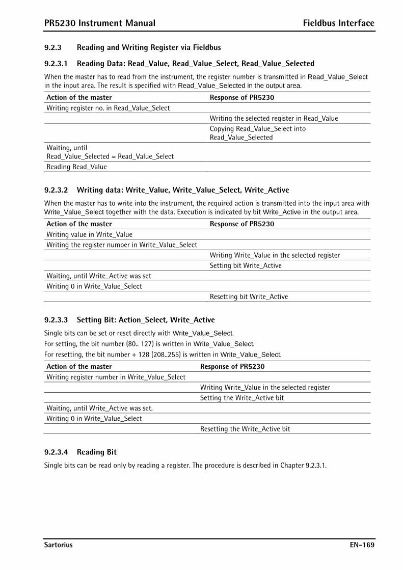
PR5230 Instrument Manual Fieldbus Interface
Sartorius EN-169
9.2.3 Reading and Writing Register via Fieldbus
9.2.3.1 Reading Data: Read_Value, Read_Value_Select, Read_Value_Selected
When the master has to read from the instrument, the register number is transmitted in Read_Value_Select in the input area. The result is specified with Read_Value_Selected in the output area.
Action of the master Response of PR5230 Writing register no. in Read_Value_Select Writing the selected register in Read_Value Copying Read_Value_Select into
Read_Value_Selected Waiting, until Read_Value_Selected = Read_Value_Select
Reading Read_Value
9.2.3.2 Writing data: Write_Value, Write_Value_Select, Write_Active
When the master has to write into the instrument, the required action is transmitted into the input area with Write_Value_Select together with the data. Execution is indicated by bit Write_Active in the output area.
Action of the master Response of PR5230 Writing value in Write_Value Writing the register number in Write_Value_Select Writing Write_Value in the selected register Setting bit Write_Active Waiting, until Write_Active was set Writing 0 in Write_Value_Select Resetting bit Write_Active
9.2.3.3 Setting Bit: Action_Select, Write_Active
Single bits can be set or reset directly with Write_Value_Select. For setting, the bit number (80.. 127) is written in Write_Value_Select. For resetting, the bit number + 128 (208..255) is written in Write_Value_Select.
Action of the master Response of PR5230 Writing register number in Write_Value_Select Writing Write_Value in the selected register Setting the Write_Active bit Waiting, until Write_Active was set. Writing 0 in Write_Value_Select Resetting the Write_Active bit
9.2.3.4 Reading Bit
Single bits can be read only by reading a register. The procedure is described in Chapter 9.2.3.1.
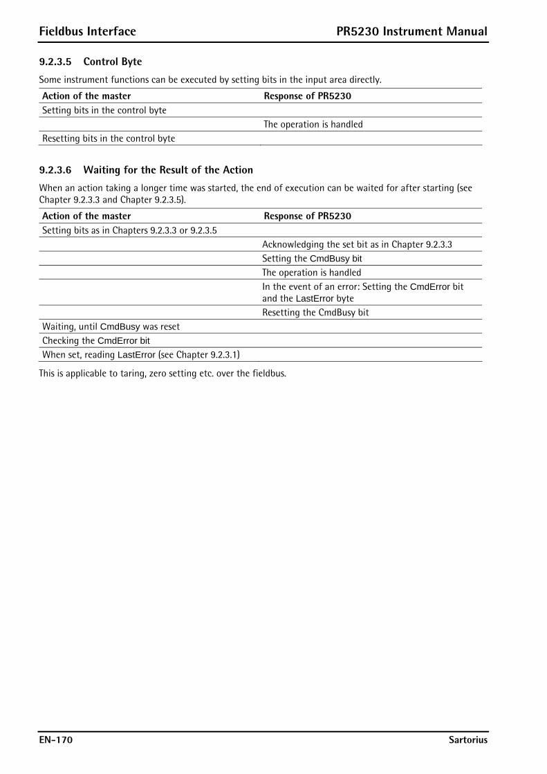
Fieldbus Interface PR5230 Instrument Manual
EN-170 Sartorius
9.2.3.5 Control Byte
Some instrument functions can be executed by setting bits in the input area directly.
Action of the master Response of PR5230 Setting bits in the control byte The operation is handled Resetting bits in the control byte
9.2.3.6 Waiting for the Result of the Action
When an action taking a longer time was started, the end of execution can be waited for after starting (see Chapter 9.2.3.3 and Chapter 9.2.3.5).
Action of the master Response of PR5230 Setting bits as in Chapters 9.2.3.3 or 9.2.3.5 Acknowledging the set bit as in Chapter 9.2.3.3 Setting the CmdBusy bit The operation is handled In the event of an error: Setting the CmdError bit
and the LastError byte Resetting the CmdBusy bit Waiting, until CmdBusy was reset Checking the CmdError bit When set, reading LastError (see Chapter 9.2.3.1)
This is applicable to taring, zero setting etc. over the fieldbus.

PR5230 Instrument Manual Fieldbus Interface
Sartorius EN-171
9.2.4 Example: Reading the Gross Weight
The master writes value 8 in Read_Value_Select (byte 4) of the input area.
Input area
Byte Value Description 0 1 2 3 4 8 Gross 5 6 7
The master waits, until value 8 was reflected in Read_Value_Selected (byte 4) of the output area.
Output area
Byte Value Description 0 00 Gross value 1 00 " 2 4 " 3 D2 " 4 8 Gross weight request
was detected 5 Status 6 Test
Active Command status
7 Stand-Still
Inside ZSR
Center Zero
Below Zero
Over-load
Above Max
Adu Error
Device status
Bit 7 Bit 6 Bit 5 Bit 4 Bit 3 Bit 3 Bit 1 Bit 0
The gross value (hex:000004D2 <=> 1234) can be read from bytes 0...3. When the 'Overload', 'Test Active' or 'ADC error' bits are set, the read value is invalid. Negative values are output in two’s complement.

Fieldbus Interface PR5230 Instrument Manual
EN-172 Sartorius
9.3 Fieldbus Register
9.3.1 Register 0: IO Status Bits for Reading
(Dynamic status), only reading is permitted
Bit 7 Bit 6 Bit 5 Bit 4 Bit 3 Bit 2 Bit 1 Bit 0 Byte 0 Input 3 Input 2 Input 1 Byte 1 Output 3 Output 2 Output 1 Byte 2 Limit 3 Limit 2 Limit 1 Byte 3
9.3.2 Register 1: Scale Status
(Dynamic status), only reading is permitted
Bit 7 Bit 6 Bit 5 Bit 4 Bit 3 Bit 2 Bit 1 Bit 0
Byte 0 DIM STND INZSR CZERO BELOW0 OVL >Max ADUERR
Byte 1 E6 E1 E3 E7
Byte 2 PowerFail ActionActive CmdError
Byte 3 TareActive CalChanged TestActive
Byte 0 corresponds to byte 7 in the output area; for weight error, see also the table in Chapter 5.5.1.
ADUERR Error of analog conversion/ load cell circuit (OR function of the E1,E3,E7 bits) >Max Gross value is higher than Max (maximum capacity); the full scale deflection was
exceeded. OVL Scale overload; Gross > Max + overload, Error 2 BELOW0 Gross weight is negative (< 0-1/4 d) CZERO Center of zero; weight within 0 +/- 1/4 d INZSR The gross weight is within the zero setting range STND The scale is stable DIM The gross weight has exceeded the full scale deflection (0-1/4 d > weight value >
Max+overload), (OR function of bits BELOW0, OVL). E7 The input signal is negative (inverse conversion), Error 7 E6 No sense voltage, or Sense voltage is low, Error 6 E3 The input signal is > 36mV (no end of conversion), Error 3 E1 Arithmetic error (overflow), Error 1 CmdError Error during execution (cmdError); e.g. the 'taring' operation is not handled, because the
scale is not stable. The error is stored in LastError (register 4). The bit is reset with the ResetError bit (register 2).
ActionActive The operation is handled; handling is busy PowerFail Power failure; is always set after power on. The PowerFail bit is reset with the ResetPWF
bit (register 2) 'Reset power failure'. TestActiv The analog test is busy TareActiv The instrument was tared.
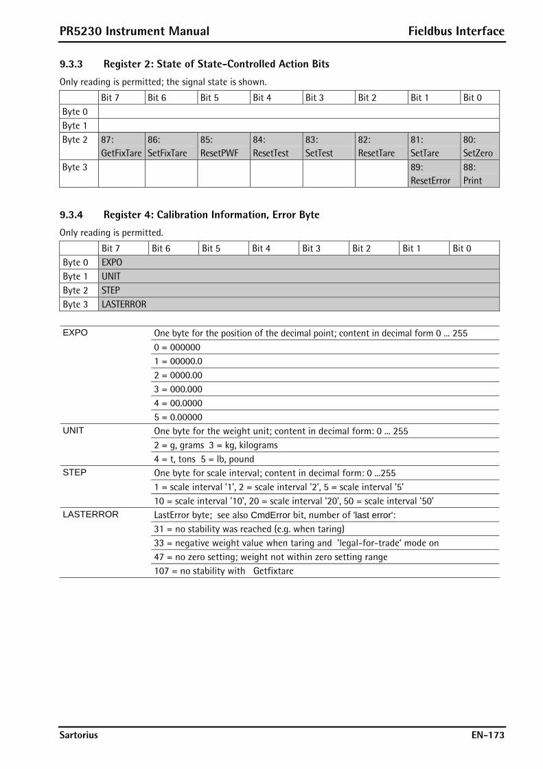
PR5230 Instrument Manual Fieldbus Interface
Sartorius EN-173
9.3.3 Register 2: State of State-Controlled Action Bits
Only reading is permitted; the signal state is shown.
Bit 7 Bit 6 Bit 5 Bit 4 Bit 3 Bit 2 Bit 1 Bit 0 Byte 0 Byte 1 Byte 2 87:
GetFixTare 86: SetFixTare
85: ResetPWF
84: ResetTest
83: SetTest
82: ResetTare
81: SetTare
80: SetZero
Byte 3 89: ResetError
88: Print
9.3.4 Register 4: Calibration Information, Error Byte
Only reading is permitted.
Bit 7 Bit 6 Bit 5 Bit 4 Bit 3 Bit 2 Bit 1 Bit 0 Byte 0 EXPO Byte 1 UNIT Byte 2 STEP Byte 3 LASTERROR
EXPO One byte for the position of the decimal point; content in decimal form 0 ... 255 0 = 000000 1 = 00000.0 2 = 0000.00 3 = 000.000 4 = 00.0000 5 = 0.00000 UNIT One byte for the weight unit; content in decimal form: 0 ... 255 2 = g, grams 3 = kg, kilograms 4 = t, tons 5 = lb, pound STEP One byte for scale interval; content in decimal form: 0 ...255 1 = scale interval '1', 2 = scale interval '2', 5 = scale interval '5' 10 = scale interval '10', 20 = scale interval '20', 50 = scale interval '50' LASTERROR LastError byte; see also CmdError bit, number of 'last error': 31 = no stability was reached (e.g. when taring) 33 = negative weight value when taring and ’legal-for-trade’ mode on 47 = no zero setting; weight not within zero setting range 107 = no stability with Getfixtare
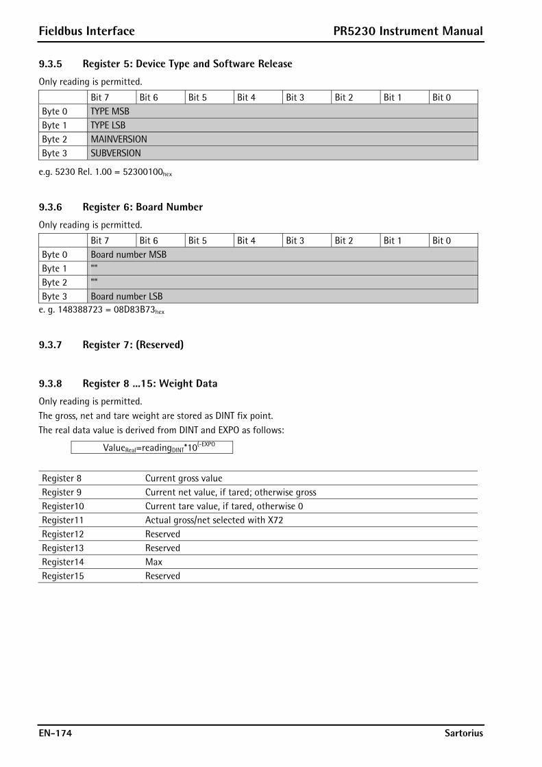
Fieldbus Interface PR5230 Instrument Manual
EN-174 Sartorius
9.3.5 Register 5: Device Type and Software Release
Only reading is permitted.
Bit 7 Bit 6 Bit 5 Bit 4 Bit 3 Bit 2 Bit 1 Bit 0 Byte 0 TYPE MSB Byte 1 TYPE LSB Byte 2 MAINVERSION Byte 3 SUBVERSION
e.g. 5230 Rel. 1.00 = 52300100hex
9.3.6 Register 6: Board Number
Only reading is permitted.
Bit 7 Bit 6 Bit 5 Bit 4 Bit 3 Bit 2 Bit 1 Bit 0 Byte 0 Board number MSB Byte 1 "" Byte 2 "" Byte 3 Board number LSB
e. g. 148388723 = 08D83B73hex
9.3.7 Register 7: (Reserved)
9.3.8 Register 8 ...15: Weight Data
Only reading is permitted. The gross, net and tare weight are stored as DINT fix point. The real data value is derived from DINT and EXPO as follows:
ValueReal=readingDINT*10(-EXPO
Register 8 Current gross value Register 9 Current net value, if tared; otherwise gross Register10 Current tare value, if tared, otherwise 0 Register11 Actual gross/net selected with X72 Register12 Reserved Register13 Reserved Register14 Max Register15 Reserved
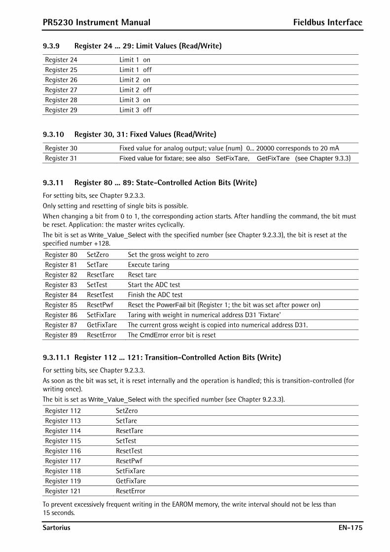
PR5230 Instrument Manual Fieldbus Interface
Sartorius EN-175
9.3.9 Register 24 ... 29: Limit Values (Read/Write)
Register 24 Limit 1 on Register 25 Limit 1 off Register 26 Limit 2 on Register 27 Limit 2 off Register 28 Limit 3 on Register 29 Limit 3 off
9.3.10 Register 30, 31: Fixed Values (Read/Write)
Register 30 Fixed value for analog output; value (num) 0... 20000 corresponds to 20 mA Register 31 Fixed value for fixtare; see also SetFixTare, GetFixTare (see Chapter 9.3.3)
9.3.11 Register 80 ... 89: State-Controlled Action Bits (Write)
For setting bits, see Chapter 9.2.3.3. Only setting and resetting of single bits is possible. When changing a bit from 0 to 1, the corresponding action starts. After handling the command, the bit must be reset. Application: the master writes cyclically. The bit is set as Write_Value_Select with the specified number (see Chapter 9.2.3.3), the bit is reset at the specified number +128.
Register 80 SetZero Set the gross weight to zero Register 81 SetTare Execute taring Register 82 ResetTare Reset tare Register 83 SetTest Start the ADC test Register 84 ResetTest Finish the ADC test Register 85 ResetPwf Reset the PowerFail bit (Register 1; the bit was set after power on) Register 86 SetFixTare Taring with weight in numerical address D31 'Fixtare' Register 87 GetFixTare The current gross weight is copied into numerical address D31. Register 89 ResetError The CmdError error bit is reset
9.3.11.1 Register 112 ... 121: Transition-Controlled Action Bits (Write)
For setting bits, see Chapter 9.2.3.3. As soon as the bit was set, it is reset internally and the operation is handled; this is transition-controlled (for writing once). The bit is set as Write_Value_Select with the specified number (see Chapter 9.2.3.3).
Register 112 SetZero Register 113 SetTare Register 114 ResetTare Register 115 SetTest Register 116 ResetTest Register 117 ResetPwf Register 118 SetFixTare Register 119 GetFixTare Register 121 ResetError
To prevent excessively frequent writing in the EAROM memory, the write interval should not be less than 15 seconds.

Global SPM Variables PR5230 Instrument Manual
EN-176 Sartorius
10 Global SPM Variables For communication via OPC, the following variables are available:
BOOL R Digital output 1 X8 BOOL R Digital output 2 X9 BOOL R Digital output 3 X10 BOOL R Digital input 1 X0 BOOL R Digital input 2 X1 BOOL R Digital input 3 X2
BOOL R Output limit 1 X16 BOOL R Output limit 2 X17 BOOL R Output limit 3 X18
BOOL R ADC error X32 BOOL R Above Max X33 BOOL R Overload, above (Max + plus the range that is still permissible) X34 BOOL R Below zero X35 BOOL R Zero +/- 1/4 d X36 BOOL R Within the zero setting range X37 BOOL R The weight is stable X38 BOOL R Below zero or above Max X39 BOOL R Load cell measuring signal negative X40 BOOL R Load cell measuring signal > 36 mV X41 BOOL R Internal arithmetic error; CAL data are perhaps faulty X42 BOOL R ADC error, overload X43 BOOL R Command error X48 BOOL R Command active X49 BOOL R Power fail signal X50 BOOL R ADC test active X56 BOOL R Calibration active X57 BOOL R Instrument is tared X58 BOOL R/W Read / write marker bit 1 X64 BOOL R/W Read / write marker bit 2 X65 BOOL R/W Read / write marker bit 3 X66 BOOL W Switch D11 to net weight X72
BOOL W Set the instrument to zero X112 BOOL W Set tare of the instrument X113 BOOL W Reset the tare of the instrument X114
BOOL W Start the ADC test X115 BOOL W Finish the ADC test X116 BOOL W Reset the power fail signal X117 BOOL W Set the fixtare value as tare X118 BOOL W Store the current gross weight in the fixtare memory (D31) X119 BOOL W Start printing X120 BOOL W Reset error X121
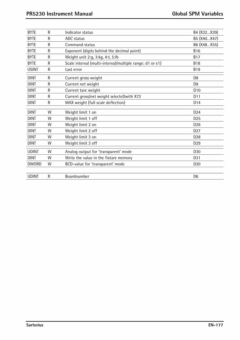
PR5230 Instrument Manual Global SPM Variables
Sartorius EN-177
BYTE R Indicator status B4 (X32…X39) BYTE R ADC status B5 (X40…X47) BYTE R Command status B6 (X48…X55) BYTE R Exponent (digits behind the decimal point) B16 BYTE R Weight unit 2:g, 3:kg, 4:t, 5:lb B17 BYTE R Scale interval (multi-interval/multiple range: d1 or e1) B18 USINT R Last error B19
DINT R Current gross weight D8 DINT R Current net weight D9 DINT R Current tare weight D10 DINT R Current gross/net weight selecteDwith X72 D11 DINT R MAX weight (full scale deflection) D14
DINT W Weight limit 1 on D24 DINT W Weight limit 1 off D25 DINT W Weight limit 2 on D26 DINT W Weight limit 2 off D27 DINT W Weight limit 3 on D28 DINT W Weight limit 3 off D29
UDINT W Analog output for 'transparent' mode D30 DINT W Write the value in the fixtare memory D31 DWORD W BCD-value for 'transparent' mode D20 UDINT R Boardnumber D6
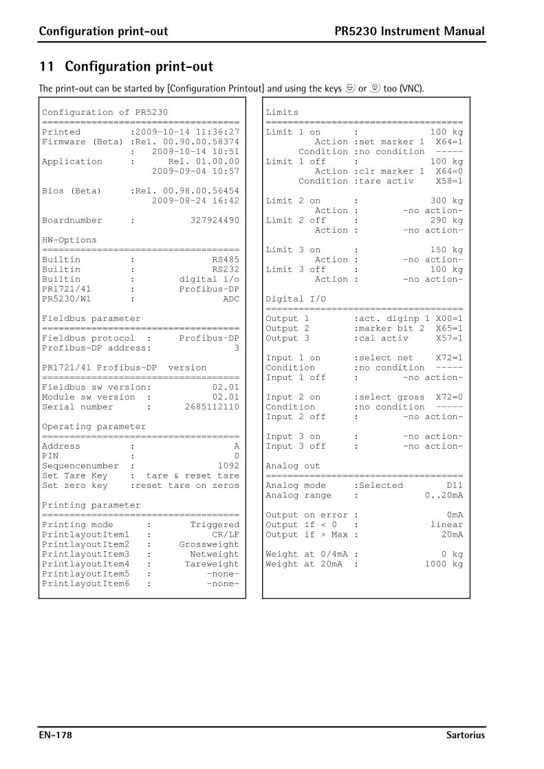
Configuration print-out PR5230 Instrument Manual
EN-178 Sartorius
11 Configuration print-out The print-out can be started by [Configuration Printout] and using the keys or too (VNC). Configuration of PR5230 ==================================== Printed :2009-10-14 11:36:27 Firmware (Beta) :Rel. 00.90.00.58374 : 2009-10-14 10:51 Application : Rel. 01.00.00 2009-09-04 10:57 Bios (Beta) :Rel. 00.98.00.56454 2009-08-24 16:42 Boardnumber : 327924490 HW-Options ==================================== Builtin : RS485 Builtin : RS232 Builtin : digital i/o PR1721/41 : Profibus-DP PR5230/W1 : ADC Fieldbus parameter ==================================== Fieldbus protocol : Profibus-DP Profibus-DP address: 3 PR1721/41 Profibus-DP version ==================================== Fieldbus sw version: 02.01 Module sw version : 02.01 Serial number : 2685112110 Operating parameter ==================================== Address : A PIN : 0 Sequencenumber : 1092 Set Tare Key : tare & reset tare Set zero key :reset tare on zeros Printing parameter ==================================== Printing mode : Triggered PrintlayoutItem1 : CR/LF PrintlayoutItem2 : Grossweight PrintlayoutItem3 : Netweight PrintlayoutItem4 : Tareweight PrintlayoutItem5 : -none- PrintlayoutItem6 : -none-
Limits ==================================== Limit 1 on : 100 kg Action :set marker 1 X64=1 Condition :no condition ----- Limit 1 off : 100 kg Action :clr marker 1 X64=0 Condition :tare activ X58=1 Limit 2 on : 300 kg Action : -no action- Limit 2 off : 290 kg Action : -no action- Limit 3 on : 150 kg Action : -no action- Limit 3 off : 100 kg Action : -no action- Digital I/O ==================================== Output 1 :act. diginp 1 X00=1 Output 2 :marker bit 2 X65=1 Output 3 :cal activ X57=1 Input 1 on :select net X72=1 Condition :no condition ----- Input 1 off : -no action- Input 2 on :select gross X72=0 Condition :no condition ----- Input 2 off : -no action- Input 3 on : -no action- Input 3 off : -no action- Analog out ==================================== Analog mode :Selected D11 Analog range : 0..20mA Output on error : 0mA Output if < 0 : linear Output if > Max : 20mA Weight at 0/4mA : 0 kg Weight at 20mA : 1000 kg

PR5230 Instrument Manual Configuration print-out
Sartorius EN-179
Serial assignment ==================================== Printer : Builtin RS232 Remote display : - none - JBUS/MOD-Bus : - none - SMA : - none - Asycom : - none – Serial port Builtin RS232 ==================================== Protocol : no protocol Baudrate : 9600 bd Bits : 8 Parity : none Stopbits : 1 Network settings ==================================== HW-address : 00:90:6C:8B:BB:0A Hostname : HOPPER 1 Use DHCP : Yes VNC-Client : 255.255.255.255 Display configuration ==================================== Item 1 : Indicator value Item 2 : Bargraph Item 3 : Limits Item 4 : Digital I/O Item 5 : Gross Item 6 : IP-address Item 7 : Net Item 8 : Fieldbus LEDs Item 9 : Tare Item 10 : Analog output Calibration ==================================== Max : 10000 kg 10000 d Scale interval 1 g Deadload at : +0.100000 mV/V : 1000.00 kg Max at : +1.000000 mV/V : 10000.00 kg Calibrated with: +1.000000 mV/V Sensitivity : 250.00 cnt/d : 1.200000 uV/d
Parameters ==================================== Measuretime : 40 ms Digital filter : off External supply : above 8V Test mode : Absolute W & M : none Standstill time : 0.08 s Standstill range : 1.00 d Tare timeout : 0.3 s Zeroset range : 9000.00 d Zerotrack range : 9000.00 d Zerotrack step : 0.00 d Zerotrack time : 0.0 s Overload : 1000 d Minimum weight : 0 d Range mode : Multiple range Range limit 1 : 0 kg Range limit 2 : 0 kg

Repairs and Maintenance PR5230 Instrument Manual
EN-180 Sartorius
12 Repairs and Maintenance Repairs are subject to inspection and must be carried out at Sartorius. In case of defect or malfunction, please contact your local Sartorius dealer or service center for repair. When returning the instrument for repair, please include a precise and complete description of the problem. Maintenance work may be carried out only by a trained technician with expert knowledge of the hazards involved and the required precautions.
12.1 Battery for Date/Time
lithium battery
The lithium battery for back-up of the calendar/time chip is located beside the power supply on the main board. The battery is activated before the instrument leaves the factory.
Note: After initial start-up, the clock must be checked and set, if necessary, under -[Date&Time].
12.1.1 Battery Replacement
The instrument is equipped with a lithium battery for back-up of the time/calendar chip. If the voltage drops below the specified minimum, or in case of defect, the battery must be replaced by the Sartorius customer service or by an equivalent trained technician. For details on disposal, see Chapter 13. For details on battery lifetime, see Chapter 14.3.1.
PR5230 Instrument Manual Disposal
Sartorius EN-181
12.2 Solder Work Soldering work on the instrument is neither required nor permitted.
12.3 Cleaning ! Disconnect the instrument from the supply voltage.
! Prevent moisture from penetrating the instrument.
! Do not use aggressive cleaning agents (solvents, etc.).
§ Clean the indicator using a piece of cloth which has been wet with a mild detergent (soap).
$ If the instrument is used in the food industry, make sure permissible cleaning agents are used.
§ Dry the instrument using a soft cloth.
! Do not wash down the equipment with water or dry it with compressed air; this is not permitted.
13 Disposal If you no longer need the packaging after successful installation of the equipment, you should discard it by the local facilities for waste disposal. The packaging is made of environmentally friendly materials and is a valuable source of secondary raw material.
Place discharged batterie in local collection boxes (not in the household waste). In Germany, corresponding collection boxes are made available by GRS (Stiftung ‘Gemeinsames Rücknahmesystem Batterien’) on request with Sartorius. For scrapping of the instrument, please contact your local authorities. Prior to scrapping, any batterie should be removed. In Germany, Sartorius AG takes care of the return and legally compliant disposal of its equipment on its own. In other countries, please consult with the local authorities.

Specifications PR5230 Instrument Manual
EN-182 Sartorius
14 Specifications
14.1 Instructions for Use of 'Free Software' The firmware in the PR5230 instrument contains free software that is licensed under: - General Public License (GPL) Version 2, June 1991, and - GNU Lesser General Public License (LGPL) Version 2.1, February 1999. This software, developed by third parties, is protected by copyright and is supplied free of charge. The license terms and conditions of Free Software Foundation, Inc in English are enclosed in the delivery of the instrument. The source text written under the above conditions is contained on the CD-ROM delivered with the instrument.
14.2 Decoding of the Serial Number
30 252 00015
30 252 00015 Location no.: 30 = Hamburg
Code of the year/month: 252* = april 2010
Current number within one month
* will count up according to the table of the year group of Sartorius
14.3 General Data Note: Technical data of PR5230 with option WE1 see Chapter 3.2.10.
The following characteristics are valid after a warm-up time of at least 60 minutes (reference temperature: 23 °C).
14.3.1 Backup Battery for Time/Date
The lithium battery for back-up of the time/calendar chip is activated before the instrument leaves the factory.
Battery lifetime at permanent running: typical 10 years
14.3.2 Power Connection 230 V AC
Supply voltage 100 V - 230 V AC +10%/-15% 50/60 Hz
Max. power consumption 12 W/15 VA Primary fuse 2x 3.15 AT, 250 V, IR 1500 A, 5x20 mm
e.g. made by Schurter: SPT5x20, order no.: 0001.2509
14.3.3 Power Connection 24 V DC
Supply voltage 24 V AC or DC -15 %/+20 %
Max. power consumption 12 W Primary fuse 2x 3.15 AT, 250 V, IR 1500 A, 5x20 mm
e.g. made by Schurter: SPT5x20, order no.: 0001.2509
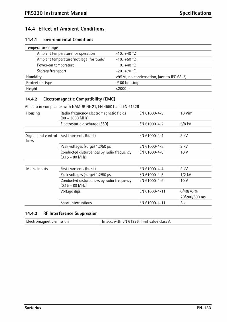
PR5230 Instrument Manual Specifications
Sartorius EN-183
14.4 Effect of Ambient Conditions
14.4.1 Environmental Conditions
Temperature range Ambient temperature for operation -10...+40 °C Ambient temperature 'not legal for trade' -10...+50 °C Power-on temperature 0...+40 °C Storage/transport -20...+70 °C Humidity <95 %, no condensation, (acc. to IEC 68-2) Protection type IP 66 housing Height <2000 m
14.4.2 Electromagnetic Compatibility (EMC)
All data in compliance with NAMUR NE 21, EN 45501 and EN 61326
Housing Radio frequency electromagnetic fields (80 – 3000 MHz)
EN 61000-4-3 10 V/m
Electrostatic discharge (ESD) EN 61000-4-2 6/8 kV Signal and control lines
Fast transients (burst) EN 61000-4-4 3 kV
Peak voltages (surge) 1.2/50 μs EN 61000-4-5 2 kV Conducted disturbances by radio frequency
(0.15 – 80 MHz) EN 61000-4-6 10 V
Mains inputs Fast transients (burst) EN 61000-4-4 3 kV Peak voltages (surge) 1.2/50 μs EN 61000-4-5 1/2 kV Conducted disturbances by radio frequency
(0.15 – 80 MHz) EN 61000-4-6 10 V
Voltage dips EN 61000-4-11 0/40/70 % 20/200/500 ms
Short interruptions EN 61000-4-11 5 s
14.4.3 RF Interference Suppression
Electromagnetic emission In acc. with EN 61326, limit value class A

Specifications PR5230 Instrument Manual
EN-184 Sartorius
14.5 Weighing Electronics The weighing electronics are suitable for connection of strain-gauge load cells.
14.5.1 Load Cells
Load cell type Strain gauge, 6 or 4-wire connection possible Supply voltage U = 12 V DC for Imax = 160 mA for
- max. 8 load cells of 650 each - 4 load cells of 350 each
Sense voltage monitoring Sense voltage below 8 V, switchable to <8 V Max. load >75 Cable length Standard Max. 500 m
14.5.2 Connecting Cable
Length of the connecting cable between junction box and PR5230
Type PR6135, PR6135A Max. 500 m – length of the load cell cable
Length of the connecting cable between weighing platform and PR5230
Type LiYCY Max. 500 m
14.5.3 Principle
Principle DC voltage, delta-sigma converter, ratiometric to the load cell supply voltage
Conversion/measurement time 5, 10, 20, 40, 80, 160, 320, 640, 960, 1200, 1600 ms Digital filter Selectable, 4th order (low-pass),
Characteristic: Bessel, aperiodic, Butterworth, Tschebyscheff Configurable cut-off frequency
14.5.4 Accuracy and Stability
The following values are applicable with a sampling rate of 160 ms.
Accuracy class 10000 e (Cl. III) acc. to OIML R76/EN 45501 Min. measuring signal (OIML) 0.66 mV/V = 8.0 mV corr. to 0.8 μV/e for 10000 e Min. measuring signal (OIML) 0.40 mV/V = 4.8 mV corr. to 0.8 μV/e for 6000 e Linearity error <0.003 % Zero stability error (TK0) <0.05 μV/K RTI <= 0,004 %/10K at 1 mV/V Span stability error (TKSpan) < ±2.5 ppm/K
14.5.5 Sensitivity
Sensitivity 0.8 μV/e Resolution 7.5 million counts at 3 mV/V, not legal for trade Input voltage (input signal + dead load)
0… max. 36 mV DC, symmetrical to 0
Dead load range 36 mV DC (max. input signal); input/calibration via software
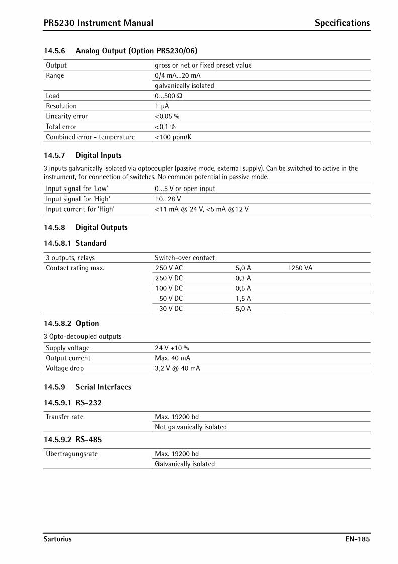
PR5230 Instrument Manual Specifications
Sartorius EN-185
14.5.6 Analog Output (Option PR5230/06)
Output gross or net or fixed preset value Range 0/4 mA…20 mA galvanically isolated Load 0…500 ¥ Resolution 1 μA Linearity error <0,05 % Total error <0,1 % Combined error - temperature <100 ppm/K
14.5.7 Digital Inputs
3 inputs galvanically isolated via optocoupler (passive mode, external supply). Can be switched to active in the instrument, for connection of switches. No common potential in passive mode.
Input signal for 'Low' 0…5 V or open input Input signal for 'High' 10…28 V Input current for 'High' <11 mA @ 24 V, <5 mA @12 V
14.5.8 Digital Outputs
14.5.8.1 Standard
3 outputs, relays Switch-over contact Contact rating max. 250 V AC 5,0 A 1250 VA 250 V DC 0,3 A 100 V DC 0,5 A 50 V DC 1,5 A 30 V DC 5,0 A
14.5.8.2 Option
3 Opto-decoupled outputs
Supply voltage 24 V +10 % Output current Max. 40 mA Voltage drop 3,2 V @ 40 mA
14.5.9 Serial Interfaces
14.5.9.1 RS-232
Transfer rate Max. 19200 bd Not galvanically isolated
14.5.9.2 RS-485
Übertragungsrate Max. 19200 bd Galvanically isolated
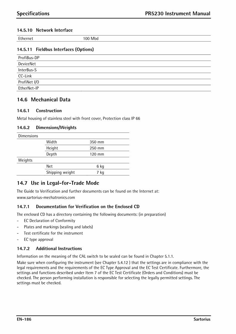
Specifications PR5230 Instrument Manual
EN-186 Sartorius
14.5.10 Network Interface
Ethernet 100 Mbd
14.5.11 Fieldbus Interfaces (Options)
ProfiBus-DP DeviceNet InterBus-S CC-Link ProfiNet I/O EtherNet-IP
14.6 Mechanical Data
14.6.1 Construction
Metal housing of stainless steel with front cover, Protection class IP 66
14.6.2 Dimensions/Weights
Dimensions Width 350 mm Height 250 mm Depth 120 mm Weights Net 6 kg Shipping weight 7 kg
14.7 Use in Legal-for-Trade Mode The Guide to Verification and further documents can be found on the Internet at: www.sartorius-mechatronics.com
14.7.1 Documentation for Verification on the Enclosed CD
The enclosed CD has a directory containing the following documents: (in preparation) - EC Declaration of Conformity - Plates and markings (sealing and labels) - Test certificate for the instrument - EC type approval
14.7.2 Additional Instructions
Information on the meaning of the CAL switch to be sealed can be found in Chapter 5.1.1. Make sure when configuring the instrument (see Chapter 5.4.12 ) that the settings are in compliance with the legal requirements and the requirements of the EC Type Approval and the EC Test Certificate. Furthermore, the settings and functions described under Item 7 of the EC Test Certificate (Orders and Conditions) must be checked. The person performing installation is responsible for selecting the legally permitted settings. The settings must be checked.

PR5230 Instrument Manual Index
Sartorius EN-187
15 Index
A
Access code ...............................................................................116
Accessories...................................................................................56
Activating Network ‚DHCP’ ....................................................82
Adapting the analog output................................................130
Analog output ..........................................................................129
Analog output board.........................................................23, 57
Asycom Protocol......................................................................162
B
Backup of EAROM...................................................................132
Battery ........................................................................................180
Bus activity..................................................................................16
Buttons .........................................................................................17
C
Cable gland..................................................................................41
Cable junction box....................................................................78
CAL switch ............................................................................81, 92
Calibration menu.......................................................................94
Calibration with mV/V value................................................103
Calibration with weight ........................................................102
CAP series.....................................................................................80
CC-Link ............................................................................... 23, 118
CC-Link Interface ......................................................................66
Cleaning .....................................................................................181
Commissioning...........................................................................81
ConfigureIt Professional .......................................................133
Connection within the Ex Area.............................................29
Connections ................................................................................22
D
Data protection..........................................................................81
Date & Time...............................................................................115
Dead load ...................................................................................100
Dead Load Correction ............................................................105
Declaration of conformity....................................................186
Determination Test Value .....................................................105
DeviceNet........................................................................... 23, 118
DeviceNet interface ..................................................................63
Digital inputs .................................................................... 42, 123
Digital outputs ................................................................. 44, 123
DIL switch S401 .........................................................................46
Display...........................................................................................14
Display board ..............................................................................39
Display items.............................................................................121
Display of calibration data..................................................... 95
Display Test Value ...................................................................105
Disposal ......................................................................................181
E
Effect of Ambient Conditions .............................................183
EMC .............................................................................................183
EN 61010 ........................................................................................9
Error 1 3 6 7..............................................................................172
Error messages .........................................................................110
error messages of the calibration......................................101
Error messages of the calibration........................................ 98
Error messages with Ex applications...................................111
Ethernet Cable ........................................................................... 72
Ethernet Socket ......................................................................... 72
EtherNet/IP.........................................................................23, 119
EtherNet/IP interface............................................................... 70
Execution message ................................................................... 89
External supply .......................................................................... 79
F
Fieldbus parameter .................................................................118
Fieldbus protocol.....................................................................118
Finishing the calibration.......................................................106
Free software............................................................................182
Fuse..............................................................................................182
H
Housing ........................................................................................ 13
Housing dimensions ................................................................. 13
I
IEC 1010..........................................................................................9
Increased resolution................................................................. 95
Indication..................................................................................... 16
IndicatorBrowser....................................................................... 85
Info key ........................................................................................ 92
Informational text .................................................................... 89
Input area ..................................................................................167
Inputs ..........................................................................................185
InterBus-S...........................................................................23, 118
InterBus-S interface................................................................. 61
Interfaces..................................................................................... 56
Internet Browser ....................................................................... 91
IO status bits for reading......................................................172

Index PR5230 Instrument Manual
EN-188 Sartorius
J
J-Bus ........................................................................................... 144
Junction board ....................................................................73, 74
Junction box ...............................................................................78
L
LAN adaptor ................................................................................42
LEDs................................................................................................16
Limit values............................................................................... 126
Load cell........................................................................................73
Load cell junction board .......................................... 23, 58, 74
M
Main board ..................................................................................38
Max ................................................................................................97
Maximum capacity....................................................................97
ModBus...................................................................................... 144
ModBus-RTU ............................................................................ 145
ModBus-TCP............................................................................. 146
ModBus-UDP ........................................................................... 146
Multi-interval scale................................................................ 109
Multiple range......................................................................... 109
N
Navigation keys..........................................................................20
Network activity ........................................................................16
Network parameter................................................................ 120
Network port ..............................................................................42
O
Opening the instrument..........................................................10
Operating concept ....................................................................81
Operating parameter............................................................. 116
Operation using Internet Browser .......................................91
Operation using the VNC program ......................................88
Operation using Web Browser ..............................................90
Operator interface.....................................................................17
Option W1....................................................................................25
Option WE1 ..........................................................................25, 27
Option Y2 ..............................................................................25, 27
Options..........................................................................................24
Optocoupler inputs ...................................................................42
Opto-decoupled Outputs ........................................................44
Output...........................................................................................23
Output area .............................................................................. 168
P
Parameter input...................................................................... 107
Potential Equalization..............................................................33
Potential-free Load Cell Supply Voltage ........................... 32
Potential-free Output.............................................................. 32
Power connection version 230 V AC................................... 10
Power connection version 24 V DC..................................... 10
Power failure .............................................................................. 81
Power on...................................................................................... 16
PR1721/41................................................................................... 59
PR1721/42................................................................................... 61
PR1721/44................................................................................... 63
PR1721/45................................................................................... 66
PR1721/46................................................................................... 68
PR1721/47................................................................................... 70
PR5230/06................................................................................... 57
PR5230/22................................................................................... 58
PR5230/30................................................................................... 72
PR5230/31................................................................................... 72
Printing parameter .................................................................117
Processing.................................................................................... 89
Production date......................................................................... 92
ProfiBus-DP........................................................................23, 118
ProfiBus-DP interface.............................................................. 59
ProfiNet I/O........................................................................23, 119
ProfiNet I/O interface .............................................................. 68
Protective earth conductor version 230 V AC ................. 10
Protective earth conductor version 24 V DC.................... 10
Q
Question mark............................................................................ 89
R
Read window............................................................................166
Reading and writing register via fieldbus .......................169
Relay Outputs............................................................................. 45
Reset.............................................................................................. 82
Resetting the Instrument ....................................................... 82
Retrieve eventlog memory...................................................131
RS-232.......................................................................................... 54
S
Safety information ......................................................................9
Saving the calibration ...........................................................106
Scale interval .............................................................................. 99
Scale status ...............................................................................172
Screenings ................................................................................... 34
Selecting the calibration mode ............................................ 96
Sequencenumber.....................................................................116
Serial interface.........................................................................112
Serial number ............................................................................. 92
Serial port ..................................................................................112
Setup menu................................................................................. 93

PR5230 Instrument Manual Index
Sartorius EN-189
Sleeve ............................................................................................41
SMA command set ..................................................................153
SMA protocol............................................................................152
smart calibration .....................................................................104
Softkeys ........................................................................................20
Specifications ...........................................................................182
Stop mark ....................................................................................89
Subsequent Dead Load Correction ....................................105
Switch S401 ................................................................................46
Switching on the instrument ................................................82
System messages .......................................................................89
T
Tare key.......................................................................................116
Tare setting................................................................................116
Technical Data of PR5230 with Option WE1....................35
Test certificate..........................................................................186
Ticket Printer...............................................................................55
Tool tip..........................................................................................21
V
VDE 0411........................................................................................ 9
VNC................................................................................................ 42
W
Warning ....................................................................................... 89
Web Browser .............................................................................. 90
Weighing electronic board ............................................. 23, 39
Weighing Electronic Board for Zone 1 and 21................ 28
Weighing Electronics .............................................................184
Weighing platforms ................................................................. 80
Weight error status .................................................................. 16
Weight status ............................................................................. 16
Write window...........................................................................166
Y
YDP04IS-OCEUV ........................................................................ 55
YDP12IS-OCEUV ........................................................................ 55
Z
Zero setting...............................................................................116
Zero-setting key ......................................................................116
zero-setting, entire.................................................................105

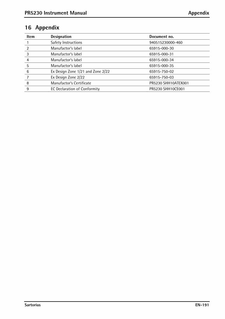
PR5230 Instrument Manual Appendix
Sartorius EN-191
16 Appendix Item Designation Document no. 1 Safety Instructions 940515230000-460 2 Manufactor’s label 65915-000-30 3 Manufactor’s label 65915-000-31 4 Manufactor’s label 65915-000-34 5 Manufactor’s label 65915-000-35 6 Ex Design Zone 1/21 and Zone 2/22 65915-750-02 7 Ex Design Zone 2/22 65915-750-03 8 Manufactor’s Certificate PR5230 SHH10ATEX001 9 EC Declaration of Conformity PR5230 SHH10CE001
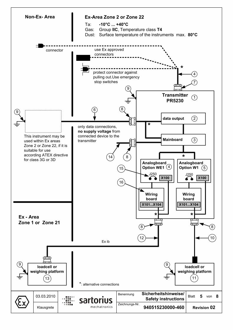
%ODWW �YRQ�
����������������
6LFKHUKHLWVKLQZHLVH�
6DIHW\�LQVWUXFWLRQV����������
.ODXVJUHWH=HLFKQXQJV�1U�
%HQHQQXQJ
5HYLVLRQ���
�
([�$UHD�=RQH���RU�=RQH���1RQ�([� $UHD
7UDQVPLWWHU�
35����
RQO\�GDWD�FRQQHFWLRQV�
QR�VXSSO\�YROWDJH�IURP
FRQQHFWHG�GHYLFH�WR�WKH
WUDQVPLWWHU
7KLV�LQVWUXPHQW�PD\�EH
XVHG�ZLWKLQ�([�DUHDV
=RQH���RU�=RQH�����LI�LW�LV
VXLWDEOH�IRU�XVH�
DFFRUGLQJ�$7(;�GLUHFWLYH
IRU�FODVV��*�RU��'
7D�� ����&���������&
*DV�� *URXS�,,&��7HPSHUDWXUH�FODVV�7�
'XVW� 6XUIDFH�WHPSHUDWXUH�RI�WKH�LQVWUXPHQWV��PD[�� ���&
SURWHFW�FRQQHFWRU�DJDLQVW�
SXOOLQJ�RXW�8VH�HPHUJHQF\
�VWRS�VZLWFKHV
FRQQHFWRU
��DOWHUQDWLYH�FRQQHFWLRQV
XVH�([�DSSURYHG�
FRQQHFWRUV
ORDGFHOO�RU
ZHLJKLQJ�SODWIRUP
� �
�
��
�
�
�
([�� $UHD
=RQH���RU��=RQH���
�
$QDORJERDUG
2SWLRQ�:(�
$QDORJERDUG
2SWLRQ�:�� �
GDWD�RXWSXW �
ORDGFHOO�RU
ZHLJKLQJ�SODWIRUP
�� ��
��
0DLQERDUG �
��
��
�
:LULQJ�
ERDUG
:LULQJ�
ERDUG
;������;���;������;���
;��� ;���
([�LE
��
-��� -���
��
�

%ODWW �YRQ�
����������������
6LFKHUKHLWVKLQZHLVH�
6DIHW\�LQVWUXFWLRQV����������
.ODXVJUHWH=HLFKQXQJV�1U�
%HQHQQXQJ
5HYLVLRQ���
6DIHW\�LQVWUXFWLRQV�IRU�LQVWDOODWLRQ��XVH��PDLQWHQDQFH�DQG�UHSDLU�RI�WKH�LQVWUXPHQW
7KH�QXPEHUV�LQ�EUDFNHWV�UHIHUV�WR�WKH�SRVLWLRQV�RQ�VKHHW���
�� 7KH�WUDQVPLWWHU�35���������LV�RQO\�ZLWK�RSWLRQ�<��VXLWDEOH�IRU�XVLQJ�ZLWKLQ�([�DUHDV�=RQH���DQG�
=RQH�����QRQ�FRQGXFWLYH�GXVW��DFFRUGLQJ�(XURSHDQ�GLUHFWLYH������(*�DQG�UHODWHG�KDUPRQL]HG�
(XURSHDQ�VWDQGDUGV� &RPSOLDQFH�ZLWK�RWKHU�UHTXLUHPHQWV�LV�QRW�VXEMHFW�RI�WKLV�LQVWUXFWLRQV��
�� 'R�QRW�XVH�WKH�WUDQVPLWWHU�DV�SRUWDEOH�LQVWUXPHQW��
�� ,QVWDOODWLRQ�PXVW�EH�SHUIRUPHG�E\�TXDOLILHG�SHUVRQQHO�LQ�FRPSOLDQFH�ZLWK�WKH�DSSOLFDEOH�ODZV��
UHJXODWLRQV��RUGLQDQFHV�DQG�VWDQGDUGV��,Q�SDUWLFXODU��WKH�VWDQGDUGV�(1�����������JDV��DQG�(1�
����������GXVW��PXVW�EH�WDNHQ�LQWR�DFFRXQW�
�� 7KH�LQIRUPDWLRQ�RQ�LQVWDOODWLRQ��RSHUDWLRQ��PDLQWHQDQFH�DQG�UHSDLU�JLYHQ�LQ�WKH�RSHUDWLRQ�PDQXDOV�
VXSSOLHG�ZLWK�WKH�HTXLSPHQW�PXVW�EH�REVHUYHG��$OVR�WKH�WHPSHUDWXU�UDQJH�RI�WKH�FRQQHFWHG�GHYLFHV�
PXVW�EH�FRQVLGHUHG�
�� 8VH�WKH�WUDQVPLWWHU�RQO\�ZLWKLQ�WKH�WHPSHUDWXUH�UDQJH�RI�����&���������&��DYRLG�H[SRVXUH�WR�
LQDGPLVVLEOH�VRXUFHV�RI�KHDW��FROG��GLUHFW�VXQOLJKW��89�UDGLDWLRQ�RU�YLEUDWLRQ��,QVWDOO�WKH�LQVWUXPHQW�LQ�
WKDW�ZD\��WKDW�DLU�FLUFXODWLRQ�LV�SRVVLEOH�DQG�KHDW�VRXUFHV�DUH�VXIILFLHQW�IDU�DZD\�
�� :LWK�2SWLRQ�9����WKH�FDEOH�����PXVW�EH�SURWHFWHG�DJDLQVW�GDPDJH�DQG�PXVW�EH�FRQQHFWHG�FRUUHWO\�
WR�PDLQV������� ����9DF��������������+]���
:LWK�2SWLRQ�9���WKH�FDEOH�����PXVW�EH�SURWHFWHG�DJDLQVW�GDPDJH�DQG�PXVW�EH�FRQQHFWHG�FRUUHWO\�WR�
��9GF����������
7KH�WUDQVPLWWHU�LV�VXLWDEOH�IRU�HOHFWULF�FLUFXLWV�XS�WR�����$��:LWKLQ�WKH�([� DUHD�WKH�VXSSO\�FDEOH�����
PXVW�EH�VXSSRUWHG�E\�DQ�DSSURYHG�FRQQHFWRU��$OWHUQDWLYH��3URWHFW�FRQQHFWRU�DJDLQVW�SXOOLQJ�RXW�RU�
FRQQHFW�GLUHFWO\��8VH�WKDQ�HPHUJHQF\�VWRS�VZLWFKHV�
�� 7KH�FRQQHFWLRQ�FDEOH������WKH�VXSSO\�FDEOH������������DQG�WKH�GDWD�FDEOH������DV�IDU�DV�WKH\�DUH�QRW�
GHOLYHUHG�E\�6DUWRULXV��PXVW�EH�TXDOLILHG�UHJDUGLQJ�([�]RQH��W\SH�RI�LQVWDOODWLRQ�DQG�WKH�HOHFWULFDO�
DQG�PHFKDQLFDO�ORDG��$OO�FDEOH�IURP�FXVWRPHU�VLGH�DUH�XQGHU�KLV�UHVSRQVLELOLW\��)RU�WKHVH��D�
TXDOLI\LQJ�H[DPLQDWLRQ�KDV�WR�EH�SHUIRUPHG��:LWK�D�SXOOLQJ�IRUFH�RI���[�FURVV�VHFWLRQ�RI�WKH�FDEOH��LQ�
PP��LQ�1��EXW�DW�OHDVW����1��RYHU���KRXUV�PXVW�QRW�PRYH�WKH�FDEOH�PRUH�WKDQ��PP�RXW�RI�WKH�FDEOH�
JODQG��8VH�FDEOH�HQG�VOHHYHV�
�� ,Q�WKH�FDVH��WKDW�FDEOH�PXVW�EH�LQVWDOOHG�ODWHU��EH�VXUH�WKDW�WKH�WHUPLQDOV�DUH�QRW�FRUURGHG��7KH�
SURWHFWLYH�HDUWK�FRQGXFWRU�RI�WKH�SRZHU�OHDG�PXVW�KDYH�WKH�VDPH�FURVV� VHFWLRQ�DV�WKH�1�DQG�/�
FRQGXFWRUV�
�� 8VH�RQO\�$7(;�DSSURYHG�FDEOH�JODQGV�����������7KH�VXSSOLHG�FDEOH�JODQGV�DUH�RQO\�ILWWLQJ�IRU�ILUP�
LQVWDOODWLRQ�LQ�WKH�([�DUHD��7KH�FDEOHV�PXVW�EH�IL[HG�QHDU�WR�WKH�FDEOH�JODQGV��H�J��ZLWK�FDEOH�FOLSV��
7KH�FDEOH�JODQGV�PD\�EH�UHSODFHG�E\�$7(;�DSSURYHG�RQHV��ILWWLQJ�IRU�IOH[LEOH�LQVWDOODWLRQ��7KH�FDEOH�
JODQGV PXVW�EH�WLJKWHQHG�ZLWK�D�WRUTXH�RI���1P�
��� 1RW�XVHG�FDEOH�JODQGV�PXVW�EH�FORVHG�ZLWK�$7(;�DSSURYHG�VUHZLQJV�LQ�RUGHU�WR�VHFXUH�,3���
SURWHFWLRQ�

%ODWW �YRQ�
����������������
6LFKHUKHLWVKLQZHLVH�
6DIHW\�LQVWUXFWLRQV����������
.ODXVJUHWH=HLFKQXQJV�1U�
%HQHQQXQJ
5HYLVLRQ���
��� 7KH�7UDQVPLWWHU�DQG�PHWDO�SDUWV��ORDG�FHOOV���ZHLJKLQJ�SODWIRUPV��PXVW�EH�FRQQHFWHG�WR�SRWHQWLDO�
HTXDOVLDWLRQ��3(�������7KLV�PHDQV�WKDW�WKH�WUDQVPLWWHU�DQG�WKH�ORDG�FHOOV���ZHLJKLQJ�SODWIRUPV�PXVW�
EH�FRQQHFWHG��ZLWK�ORZ�UHVLVWDQFH��WR�WKH�VDPH�3(������$OO�FRQQHFWHG�QRQ�LQWULQVLF�VDIH�GHYLFHV�ZLWK�
8P� ����9�PXVW�DOVR�EH�FRQQHFWHG�WR�3(������7KLV�3(�����PXVW�EH�FRQQHFWHG�WR�WKH�3(�����IURP�WKH�
([�$UHD�ZLWK�ORZ�UHVLVWDQFH��)RU�WKLV�SXUSRVH��WKH�XVHU�KDV�WR�FRQQHFW�D�FRQGXFWRU�ZLWK�D�FURVV�
VHFWLRQ�RI�DW�OHDVW��PPð�DW�VXLWDEOH�SRLQWV��)LWWLQJ�SDUWV�OLNH�VFUHZV�FDQ�EH�XVHG��,I�D�IOH[LEOH�
FRQGXFWRU�LV�XVHG��LW�PXVW�KDV�D�ULQJ�H\H��IRU�D�VDYH�PRXQWLQJ��7KH�LQVWDOODWLRQ�PXVW�EH�VDYH��
DJDLQVW�VHOI�ORRVHQLQJ��&KHFN�WKLV�FRQQHFWLRQ�WR�WKH�3(�UDLO�WR�EH�RI�ORZ�UHVLVWDQFH��GXULQJ�RQ�VLGH�
LQVWDOODWLRQ�DQG�SHULRGLFDO�WLPH�ODJ�DIWHUZDUGV��3UHYHQWLRQ�DJDLQVW�HOHFWURVWDWLF�FKDUJLQJ�LV�XQGHU�WKH�
UHVSRQVLELOLW\�RI�WKH�FXVWRPHU�
��� %HIRUH�RSHQLQJ�WKH�LQVWUXPHQW��VZLWFK�RII�WKH�VXSSO\�YROWDJH��RU�PDNH�VXUH�WKDW�WKH�DUHD�LV�QRW�
SRWHQWLDOO\�H[SORVLYH��'R�QRW�FRQQHFW�RU�GLVFRQQHFW�DQ\�OLYH�FDOEHV�LQVLGH�WKH�KD]DUGRXV�DUHD�
��� 7KH�LQIOXHQFH�RI�VWUD\�HOHFWULFDO�LQWHUIHUHQFHV��H�J��GXH�WR�PDJQHWLF�ILHOGV��PXVW�EH�DYRLGHG�E\�
PHDQV�RI�SURSHU�LQVWDOODWLRQ�
��� &KHPLFDOV�WKDW�FDQ�DWWDFN�KRXVLQJ�JDVNHWV�DQG�FDEOH�VKHDWKLQJV�PXVW�EH�NHSW�DZD\�IURP�WKH�
LQVWUXPHQW��7KHVH�LQFOXGHV�RLO��KHUEDO�DQG�DQLPDOLVWLF�JUHDVH��SHWURO��FKORULQDWHG�DQG�IODYRXUHG�
VROYHQW��EDVH�DQG�DFLG��DFHWRQH�DQG�R]RQH��,I�\RX�DUH�XQFHUWDLQ��FRQWDFW�WKH�PDQXIDFWXUHU�
��� 'DWD�FDEOH�WR�WKH�FRQQHFWHG�GHYLFHV�DQG�FDEOH�WR�WKH�ORDG�FHOOV�DUH�QRW�VSDUNLQJ�FLUFXLWV��7KH�
FRQQHFWLRQV�DUH�VHFXUHG�DJDLQVW�XQLQWHQGHG�GLVFRQQHFWLRQ��&RQQHFW�RU�GLVFRQQHFW�RQO\�ZKHQ�
SRZHU�LV�VZLWFKHG�RII��1RW�XVHG�RXWSXWV�PXVW�EH�FORVHG�DFFRUGLQJ�,3����.HHS�YROWDJH�WUDQVLHQWV�
DZD\�IURP�WKH�GHYLFH�
��� 8VH�RQO\�GDWD�RXWSXWV������VXSSOLHG�E\�6DUWRULXV�IRU�WKH�35������7KLV�RSWLRQV�PXVW�EH�LQVWDOOHG�
FRUUHFWO\��VHFXUH�DJDLQVW�VHOI�ORRVHQLQJ��DQG�PXVW�EH�FRQQHFWHG�ZLWK�WKH�PDLQERDUG�DFFRUGLQJ�WR�
WKH�LQVWUXFWLRQV�
��� 5HODLV��:LWK�2SWLRQ�<���RQO\�H[WHUQDO�FLUFXLWV������ZLWK�YROWDJHV�XS�WR���9DF�RU���9GF�DUH�DOORZHG�
WR�EH�FRQQHFWHG�WR�WKH�UHODLV�
��� 2SWLRQ�:�������&RQQHFWHG�ORDG�FHOOV�RU�ZHLJKLQJ�SODWIRUPV������PXVW�EH�FHUWLILHG�IRU�XVH�LQ�([�
DUHDV�=RQH���RU�=RQH����DQG�IRU�ORDG�FHOO�VXSSO\�YROWDJHV�RI�PRUH�WKDQ�����9��2EVHUYH�JDV�JURXS�
DQG�WHPSHUDWXUH�FODVV�ZKHQ�XVH�LQ�([�DUHD�=RQH����:KHQ�XVH�LQ�=RQH�����REVHUYH�WKH�DOORZHG�
VXUIDFH�WHPSHUDWXUH��
����2SWLRQ�:(���,Q�WKLV�FDVH�WKH�7UDQVPLWWHU�35������LQWULQVLF�VDIH�RXWSXW�WR�ORDG�FHOOV���ZHLJKLQJ�
SODWIRUPV��ZLOO�EH�GHOLYHUHG��VR�WKDW�WKH�LQWULQVLF�FLUFXLW���&RQQHFWRU�;����IURP�WKH�$QDORJERDUG�RU�
WKH�FRQQHFWRUV�;�������;����IURP�WKH�ZLULQJERDUG��LI�H[LVW��LV�FRQQHFWHG�WR�3(��
,I�LW�LV�QHFHVVDU\�WR�XVH�DQ�SRWHQWLDO�IUHH�RXWSXW��LW�LV�SRVVLEOH�WR�RSHQ�WKH�-XPSHU�-�����&XW�ERWK�
HQGV�IURP�WKH�-XPSHU�VKRUW�RYHU�WKH�3&%�VXUIDFH��VR�WKDW�WKH�GLVWDQFH�EHWZHHQ�WKH�HQGV�LV�!��PP�
DQG�WKHUH�LV�QR�FRQQHFWLRQ�WR�DQ\�RWKHU�SRWHQWLDO��
,I�-����LV�RSHQ��WKH�LQWULQVLF�FLUFXLW�LV�JDOYDQLFDOO\�VHSDUDWHG�IURP�WKH�KRXVLQJ��3(������9�WHVW�
YROWDJH���
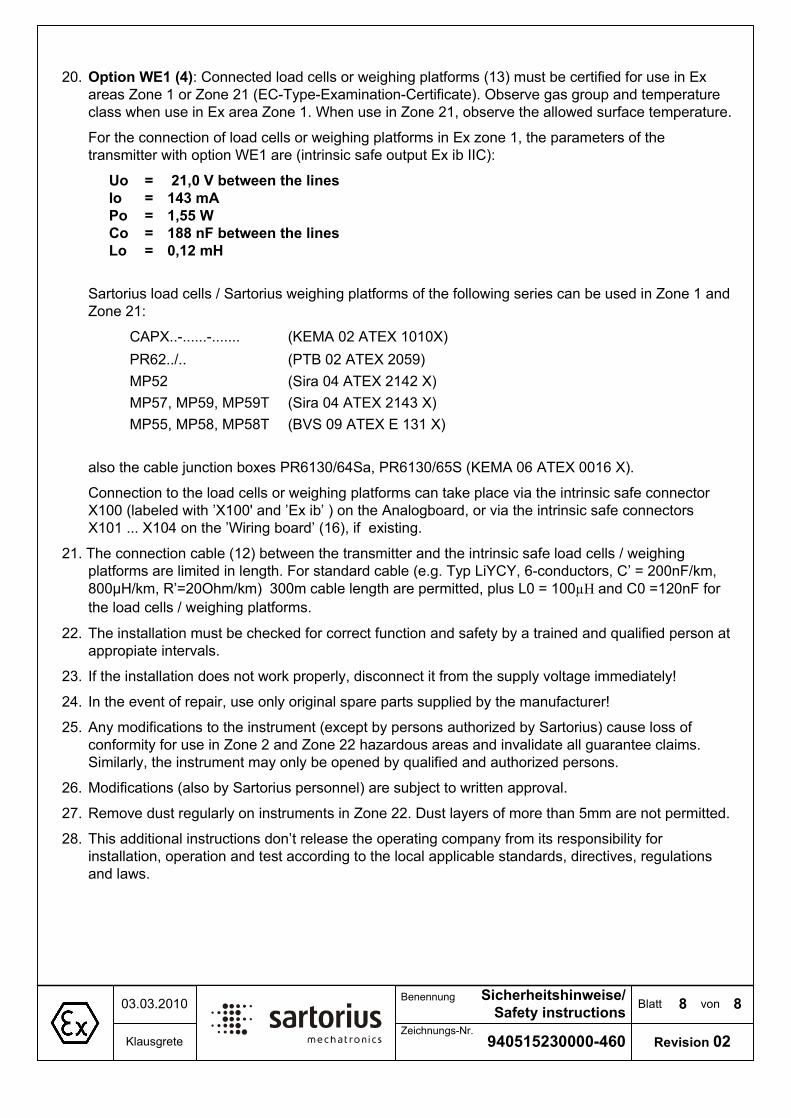
%ODWW �YRQ�
����������������
6LFKHUKHLWVKLQZHLVH�
6DIHW\�LQVWUXFWLRQV����������
.ODXVJUHWH=HLFKQXQJV�1U�
%HQHQQXQJ
5HYLVLRQ���
��� 2SWLRQ�:(�������&RQQHFWHG�ORDG�FHOOV�RU�ZHLJKLQJ�SODWIRUPV������PXVW�EH�FHUWLILHG�IRU�XVH�LQ�([�
DUHDV�=RQH���RU�=RQH�����(&�7\SH�([DPLQDWLRQ�&HUWLILFDWH���2EVHUYH�JDV�JURXS�DQG�WHPSHUDWXUH�
FODVV�ZKHQ�XVH�LQ�([�DUHD�=RQH����:KHQ�XVH�LQ�=RQH�����REVHUYH�WKH�DOORZHG�VXUIDFH�WHPSHUDWXUH��
)RU�WKH�FRQQHFWLRQ�RI�ORDG�FHOOV�RU�ZHLJKLQJ�SODWIRUPV�LQ�([�]RQH����WKH�SDUDPHWHUV�RI�WKH�
WUDQVPLWWHU�ZLWK�RSWLRQ�:(��DUH��LQWULQVLF�VDIH�RXWSXW�([�LE�,,&��
8R ������9�EHWZHHQ�WKH�OLQHV
,R ����P$
3R �����:
&R ����Q)�EHWZHHQ�WKH�OLQHV
/R �����P+
6DUWRULXV�ORDG�FHOOV���6DUWRULXV�ZHLJKLQJ�SODWIRUPV�RI�WKH�IROORZLQJ�VHULHV�FDQ�EH�XVHG�LQ�=RQH���DQG�
=RQH����
&$3;������������������ �.(0$����$7(;�����;��
35�������� �37%����$7(;�������
03��� �6LUD����$7(;������;�
03����03����03��7 �6LUD����$7(;������;��
03����03����03��7 �%96����$7(;�(�����;��
DOVR�WKH�FDEOH�MXQFWLRQ�ER[HV�35�������6D��35�������6��.(0$����$7(;������;��
&RQQHFWLRQ�WR�WKH�ORDG�FHOOV�RU�ZHLJKLQJ�SODWIRUPV�FDQ�WDNH�SODFH�YLD�WKH�LQWULQVLF�VDIH�FRQQHFWRU���
;�����ODEHOHG�ZLWK�¶;����DQG�¶([�LE¶���RQ�WKH�$QDORJERDUG��RU�YLD�WKH�LQWULQVLF�VDIH�FRQQHFWRUV���
;��������;����RQ�WKH�¶:LULQJ�ERDUG¶�������LI��H[LVWLQJ��
����7KH�FRQQHFWLRQ�FDEOH������EHWZHHQ�WKH�WUDQVPLWWHU�DQG�WKH�LQWULQVLF�VDIH�ORDG�FHOOV���ZHLJKLQJ�
SODWIRUPV�DUH�OLPLWHG�LQ�OHQJWK��)RU�VWDQGDUG�FDEOH��H�J��7\S�/L<&<����FRQGXFWRUV��&¶� ����Q)�NP��
����+�NP��5¶ ��2KP�NP�� ���P�FDEOH�OHQJWK�DUH�SHUPLWWHG��SOXV�/�� �����+�DQG�&�� ���Q)�IRU�
WKH�ORDG�FHOOV���ZHLJKLQJ�SODWIRUPV�
��� 7KH�LQVWDOODWLRQ�PXVW�EH�FKHFNHG�IRU�FRUUHFW�IXQFWLRQ�DQG�VDIHW\�E\�D�WUDLQHG�DQG�TXDOLILHG�SHUVRQ�DW�
DSSURSLDWH�LQWHUYDOV�
��� ,I�WKH�LQVWDOODWLRQ�GRHV�QRW�ZRUN�SURSHUO\��GLVFRQQHFW�LW�IURP�WKH�VXSSO\�YROWDJH�LPPHGLDWHO\�
��� ,Q�WKH�HYHQW�RI�UHSDLU��XVH�RQO\�RULJLQDO�VSDUH�SDUWV�VXSSOLHG�E\�WKH�PDQXIDFWXUHU�
��� $Q\�PRGLILFDWLRQV�WR�WKH�LQVWUXPHQW��H[FHSW�E\�SHUVRQV�DXWKRUL]HG�E\�6DUWRULXV��FDXVH�ORVV�RI�
FRQIRUPLW\�IRU�XVH�LQ�=RQH���DQG�=RQH����KD]DUGRXV�DUHDV�DQG�LQYDOLGDWH�DOO�JXDUDQWHH�FODLPV��
6LPLODUO\��WKH�LQVWUXPHQW�PD\�RQO\�EH�RSHQHG�E\�TXDOLILHG�DQG�DXWKRUL]HG�SHUVRQV�
��� 0RGLILFDWLRQV��DOVR�E\�6DUWRULXV�SHUVRQQHO��DUH�VXEMHFW�WR�ZULWWHQ�DSSURYDO�
��� 5HPRYH�GXVW�UHJXODUO\�RQ�LQVWUXPHQWV�LQ�=RQH�����'XVW�OD\HUV�RI�PRUH�WKDQ��PP�DUH�QRW�SHUPLWWHG�
��� 7KLV�DGGLWLRQDO�LQVWUXFWLRQV�GRQ¶W�UHOHDVH�WKH�RSHUDWLQJ�FRPSDQ\�IURP�LWV�UHVSRQVLELOLW\�IRU�
LQVWDOODWLRQ��RSHUDWLRQ�DQG�WHVW�DFFRUGLQJ�WR�WKH�ORFDO�DSSOLFDEOH�VWDQGDUGV��GLUHFWLYHV��UHJXODWLRQV�
DQG�ODZV�

.HQQ]HLFKQXQJVVFKLOG
0DQXIDFWXUHUV�ODEHO �%ODWW
6KHHW
�YRQ
RI
0D�VWDE���
6FDOH
���
��9�$������
$XVJDEH���5HYLVLRQ
��)UHLJDEH
5HOHDVHG�E\
*HSU�IW
5HYLHZHG�E\
(UVWHOOW
:ULWWHQ�E\
��������
��������
��������
'DWXP
'DWH
.ODXVJUHWH
.ODXVJUHWH
.ODXVJUHWH
1DPH0DWHULDO
������������
%HQHQQXQJ���7LWOH
bQGHUXQJ���$OWHUDWLRQ
���
=HLFKQXQJV�1U����'UDZLQJ�QXPEHU
����PP�GLFN
6\PERO�XQG�6FKULIW��VFKZDU]�5$/�������JHlW]W��YHUWLHIW
2EHUIOlFKH��EODQN�HUKDEHQ��SROLHUW
����PP�WKLFN
6\PERO�DQG�ODEHOLQJ��EODFN��5$/������VWDQGDUG��HWFKHG��UHFHVVHG
6XUIDFH��EODQN�DQG�UDLVHG��SROLVKHG
��
���
������������
6DUWRULXV�0HFKDWURQLFV�7+�*PE+� ������+DPEXUJ��*HUPDQ\
������
����&� �7D� �����&
����
35����
2SWLRQ�
:(���<���
,, ���*�>([�LE@,,&�
,,����'�>([�LE'@��
.(0$���$7(;�����;
,,��*�([�Q$�Q&�,,&�7�
,,��'�([�W'�$���,3�;�7���&
6$*���$7(;���;
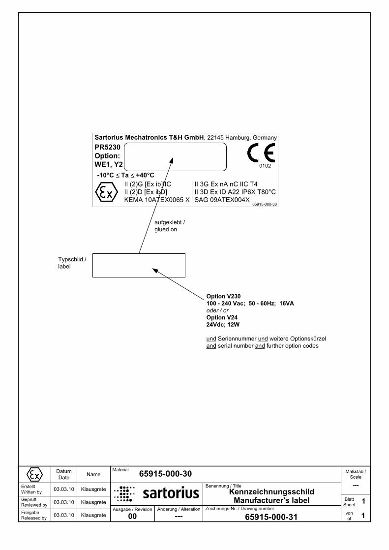
.HQQ]HLFKQXQJVVFKLOG
0DQXIDFWXUHUV�ODEHO �%ODWW
6KHHW
�YRQ
RI
0D�VWDE���
6FDOH
���
������������
$XVJDEH���5HYLVLRQ
��)UHLJDEH
5HOHDVHG�E\
*HSU�IW
5HYLHZHG�E\
(UVWHOOW
:ULWWHQ�E\
��������
��������
��������
'DWXP
'DWH
.ODXVJUHWH
.ODXVJUHWH
.ODXVJUHWH
1DPH0DWHULDO
������������
%HQHQQXQJ���7LWOH
bQGHUXQJ���$OWHUDWLRQ
���
=HLFKQXQJV�1U����'UDZLQJ�QXPEHU
������������
6DUWRULXV�0HFKDWURQLFV�7+�*PE+� ������+DPEXUJ��*HUPDQ\
������
����&� �7D� �����&
35����
2SWLRQ�
:(���<���
,, ���*�>([�LE@,,&�
,,����'�>([�LE'@��
.(0$���$7(;�����;
,,��*�([�Q$�Q&�,,&�7�
,,��'�([�W'�$���,3�;�7���&
6$*���$7(;���;
2SWLRQ�9���
����� ����9DF������� ��+]�����9$
RGHU���RU
2SWLRQ�9��
��9GF����:
XQG�6HULHQQXPPHU�XQG�ZHLWHUH�2SWLRQVN�U]HO
DQG�VHULDO�QXPEHU�DQG�IXUWKHU�RSWLRQ�FRGHV
7\SVFKLOG��
ODEHO
DXIJHNOHEW��
JOXHG�RQ
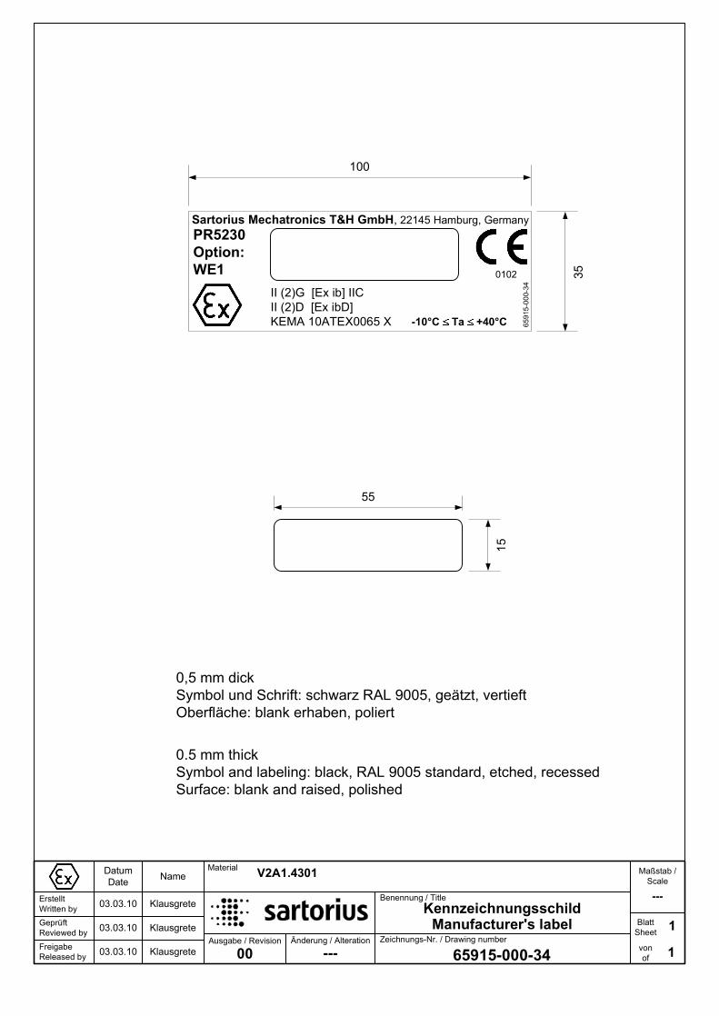
.HQQ]HLFKQXQJVVFKLOG
0DQXIDFWXUHUV�ODEHO �%ODWW
6KHHW
�YRQ
RI
0D�VWDE���
6FDOH
���
��9�$������
$XVJDEH���5HYLVLRQ
��)UHLJDEH
5HOHDVHG�E\
*HSU�IW
5HYLHZHG�E\
(UVWHOOW
:ULWWHQ�E\
��������
��������
��������
'DWXP
'DWH
.ODXVJUHWH
.ODXVJUHWH
.ODXVJUHWH
1DPH0DWHULDO
������������
%HQHQQXQJ���7LWOH
bQGHUXQJ���$OWHUDWLRQ
���
=HLFKQXQJV�1U����'UDZLQJ�QXPEHU
����PP�GLFN
6\PERO�XQG�6FKULIW��VFKZDU]�5$/�������JHlW]W��YHUWLHIW
2EHUIOlFKH��EODQN�HUKDEHQ��SROLHUW
����PP�WKLFN
6\PERO�DQG�ODEHOLQJ��EODFN��5$/������VWDQGDUG��HWFKHG��UHFHVVHG
6XUIDFH��EODQN�DQG�UDLVHG��SROLVKHG
��
���
������������
6DUWRULXV�0HFKDWURQLFV�7+�*PE+� ������+DPEXUJ��*HUPDQ\
,,����*��>([�LE@�,,&��
,,����'��>([�LE'@
.(0$���$7(;�����;
������
����&� �7D� �����&
����
35����
2SWLRQ�
:(���

.HQQ]HLFKQXQJVVFKLOG
0DQXIDFWXUHUV�ODEHO �%ODWW
6KHHW
�YRQ
RI
0D�VWDE���
6FDOH
���
������������
$XVJDEH���5HYLVLRQ
��)UHLJDEH
5HOHDVHG�E\
*HSU�IW
5HYLHZHG�E\
(UVWHOOW
:ULWWHQ�E\
��������
��������
��������
'DWXP
'DWH
.ODXVJUHWH
.ODXVJUHWH
.ODXVJUHWH
1DPH0DWHULDO
������������
%HQHQQXQJ���7LWOH
bQGHUXQJ���$OWHUDWLRQ
���
=HLFKQXQJV�1U����'UDZLQJ�QXPEHU
������������
6DUWRULXV�0HFKDWURQLFV�7+�*PE+� ������+DPEXUJ��*HUPDQ\
,,����*��>([�LE@�,,&��
,,����'��>([�LE'@
.(0$���$7(;�����;
������
����&� �7D� �����&
35����
2SWLRQ�
:(���
2SWLRQ�9���
����� ����9DF������� ��+]�����9$
RGHU���RU
2SWLRQ�9��
��9GF����:
XQG�6HULHQQXPPHU�XQG�ZHLWHUH�2SWLRQVN�U]HO
DQG�VHULDO�QXPEHU�DQG�IXUWKHU�RSWLRQ�FRGHV
7\SVFKLOG��
ODEHO
DXIJHNOHEW��
JOXHG�RQ
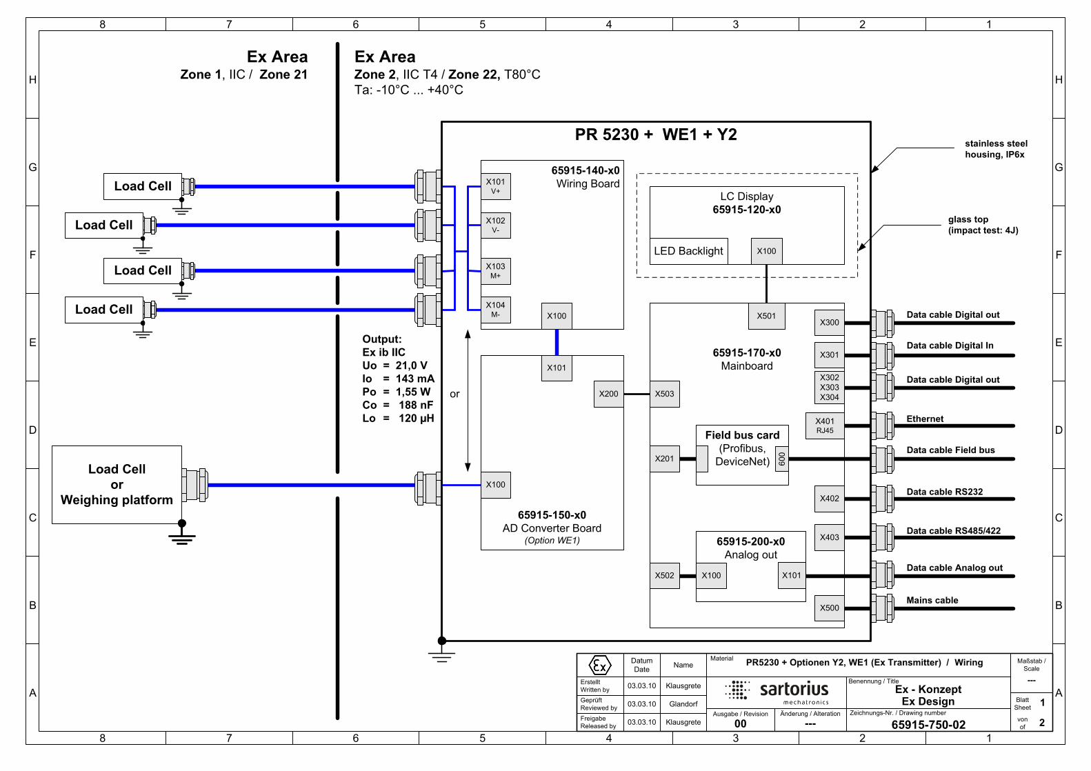
([�� .RQ]HSW�
([�'HVLJQ
+
*
)
(
'
&
%
$
� � � � � � � �
+
*
)
(
'
&
%
$
� � � � � � � �
�%ODWW
6KHHW
�YRQ
RI
0D�VWDE���
6FDOH
���
�35�������2SWLRQHQ�<���:(���([�7UDQVPLWWHU����
$XVJDEH���5HYLVLRQ
��)UHLJDEH
5HOHDVHG�E\
*HSU�IW
5HYLHZHG�E\
(UVWHOOW
:ULWWHQ�E\
��������
��������
��������
'DWXP
'DWH
.ODXVJUHWH
*ODQGRUI
.ODXVJUHWH
1DPH0DWHULDO
������������
%HQHQQXQJ���7LWOH
bQGHUXQJ���$OWHUDWLRQ
���
=HLFKQXQJV�1U����'UDZLQJ�QXPEHU
����������[�
0DLQERDUG
����������[�
$'�&RQYHUWHU�%RDUG�2SWLRQ�:(��
/&�'LVSOD\
����������[�
/('�%DFNOLJKW
:LULQJ
([�$UHD=RQH����,,&����=RQH���
([�$UHD=RQH����,,&�7����=RQH�����7���&
7D������&���������&
;���
2XWSXW�
([�LE�,,&
8R �������9
,R ������P$
3R �������:
&R ����Q)
/R �����+
;���
;���
;���
VWDLQOHVV�VWHHO�
KRXVLQJ��,3�[
JODVV�WRS
�LPSDFW�WHVW���-�
����������[�
:LULQJ�%RDUG
/RDG�&HOO�
RU
:HLJKLQJ�SODWIRUP
;���
RU
0DLQV�FDEOH;���
'DWD�FDEOH�'LJLWDO�RXW;���
;���
5-��
'DWD�FDEOH�56���;���
'DWD�FDEOH�56�������;���
����������[�
$QDORJ�RXW
;���;��� ;���
;���
9�/RDG�&HOO�
/RDG�&HOO�
/RDG�&HOO�
/RDG�&HOO�
;���
9�
;���
0�
;���
0�
(WKHUQHW
;���
;���
;���
'DWD�FDEOH�$QDORJ�RXW
'DWD�FDEOH�'LJLWDO�RXW
)LHOG�EXV�FDUG
�3URILEXV��
'HYLFH1HW�;���
���
'DWD�FDEOH�)LHOG�EXV
35���������:(����<�
'DWD�FDEOH�'LJLWDO�,Q;���
;���
;���
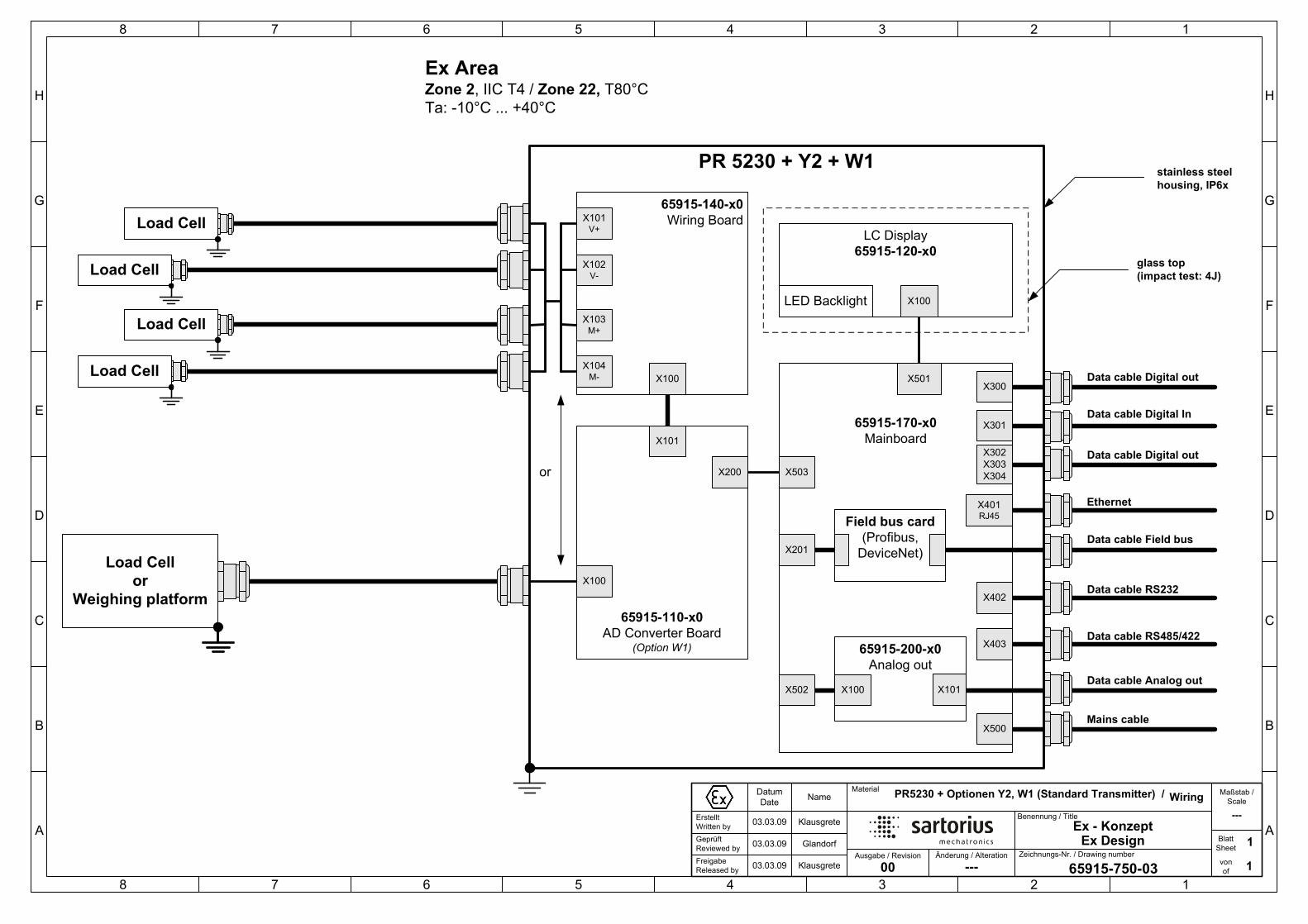
([�� .RQ]HSW�
([�'HVLJQ
+
*
)
(
'
&
%
$
� � � � � � � �
+
*
)
(
'
&
%
$
� � � � � � � �
�%ODWW
6KHHW
�YRQ
RI
0D�VWDE���
6FDOH
���
�35�������2SWLRQHQ�<���:���6WDQGDUG�7UDQVPLWWHU����
$XVJDEH���5HYLVLRQ
��)UHLJDEH
5HOHDVHG�E\
*HSU�IW
5HYLHZHG�E\
(UVWHOOW
:ULWWHQ�E\
��������
��������
��������
'DWXP
'DWH
.ODXVJUHWH
*ODQGRUI
.ODXVJUHWH
1DPH0DWHULDO
������������
%HQHQQXQJ���7LWOH
bQGHUXQJ���$OWHUDWLRQ
���
=HLFKQXQJV�1U����'UDZLQJ�QXPEHU
����������[�
0DLQERDUG
����������[�
$'�&RQYHUWHU�%RDUG�2SWLRQ�:��
/&�'LVSOD\
����������[�
/('�%DFNOLJKW
:LULQJ
([�$UHD=RQH����,,&�7����=RQH�����7���&
7D������&���������&
;��� ;���
;���
;���
VWDLQOHVV�VWHHO�
KRXVLQJ��,3�[
JODVV�WRS
�LPSDFW�WHVW���-�
����������[�
:LULQJ�%RDUG
/RDG�&HOO�
RU
:HLJKLQJ�SODWIRUP
;���
RU
0DLQV�FDEOH;���
'DWD�FDEOH�'LJLWDO�RXW;���
;���
5-��
'DWD�FDEOH�56���;���
'DWD�FDEOH�56�������;���
����������[�
$QDORJ�RXW
;���;��� ;���
;���
9�/RDG�&HOO�
/RDG�&HOO�
/RDG�&HOO�
/RDG�&HOO�
;���
9�
;���
0�
;���
0�
(WKHUQHW
;���
;���
;���
'DWD�FDEOH�$QDORJ�RXW
'DWD�FDEOH�'LJLWDO�RXW
)LHOG�EXV�FDUG
�3URILEXV��
'HYLFH1HW�;���'DWD�FDEOH�)LHOG�EXV
35��������<����:�
'DWD�FDEOH�'LJLWDO�,Q;���
;���
;���

HerstellerbescheinigungManufacturer s Certificate
_____________________________________________________________________________________________SHH10ATEX001 1 / 2 SOP-3.RD-045-fo4
Sartorius Mechatronics T&H GmbHMeiendorfer Str. 20522145 HamburgGermany
bescheinigt in alleiniger Verantwortung, dass das Produktcertifies under our sole responsibility that the product
Transmitter PR5230 + Option Y2, W1, WE1
auf das sich diese Bescheinigung bezieht, mit der/den folgenden Norm(en) oder normativenDokument(en) übereinstimmt (siehe Seite 2) gemäß den Bestimmungen der Richtlinie 94/9/EG desEuropäischen Parlaments und des Rates vom 23. März 1994 zur Angleichung der Rechtsvorschriftender Mitgliedstaaten für Geräte und Schutzsysteme zur bestimmungsgemäßen Verwendung inexplosionsgefährdeten Bereichen .
to which this certification relates is in conformity with the following standard(s) or other normativedocument(s) (see page 2) pursuant to the provisions of the Directive 94/9/EC of the EuropeanParliament and the Council of 23 March 1994 on the approximation of the laws of the Member Statesconcerning equipment and protective systems intended for use in potentially explosive atmospheres .
Diese Erklärung bescheinigt die Übereinstimmung mit der genannten Richtlinie, beinhaltet jedochkeine Zusicherung von Eigenschaften. Die Sicherheitshinweise der mitgelieferten Produkt-dokumentation sind zu beachten.
This declaration certifies conformity with the Directive listed above, but does not constitute anasseveration of characteristics. The safety directions of the delivered product documentation must befollowed.
Sartorius Mechatronics T&H GmbHHamburg, 2010-03-31
_____________________________________ _________________________________________
Lothar Golla Kathrin FörsterEx Approval Manager Quality Management
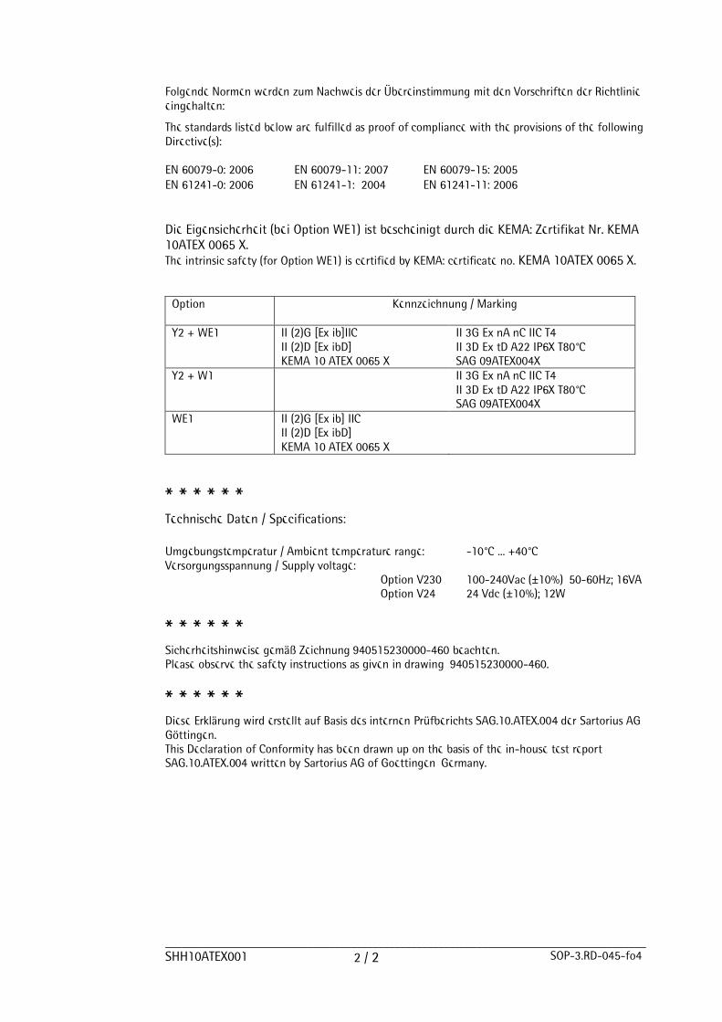
________________________________________________________________________________________SHH10ATEX001 2 / 2 SOP-3.RD-045-fo4
Folgende Normen werden zum Nachweis der Übereinstimmung mit den Vorschriften der Richtlinieeingehalten:
The standards listed below are fulfilled as proof of compliance with the provisions of the followingDirective(s):
EN 60079-0: 2006 EN 60079-11: 2007 EN 60079-15: 2005EN 61241-0: 2006 EN 61241-1: 2004 EN 61241-11: 2006
Die Eigensicherheit (bei Option WE1) ist bescheinigt durch die KEMA: Zertifikat Nr. KEMA10ATEX 0065 X.The intrinsic safety (for Option WE1) is certified by KEMA: certificate no. KEMA 10ATEX 0065 X.
Option Kennzeichnung / Marking
Y2 + WE1 II (2)G [Ex ib]IICII (2)D [Ex ibD]KEMA 10 ATEX 0065 X
II 3G Ex nA nC IIC T4II 3D Ex tD A22 IP6X T80°CSAG 09ATEX004X
Y2 + W1 II 3G Ex nA nC IIC T4II 3D Ex tD A22 IP6X T80°CSAG 09ATEX004X
WE1 II (2)G [Ex ib] IICII (2)D [Ex ibD]KEMA 10 ATEX 0065 X
* * * * * *Technische Daten / Specifications:
Umgebungstemperatur / Ambient temperature range: -10°C ... +40°CVersorgungsspannung / Supply voltage:
Option V230 100-240Vac (±10%), 50-60Hz; 16VA Option V24 24 Vdc (±10%); 12W
* * * * * *Sicherheitshinweise gemäß Zeichnung 940515230000-460 beachten.Please observe the safety instructions as given in drawing 940515230000-460.
* * * * * *Diese Erklärung wird erstellt auf Basis des internen Prüfberichts SAG.10.ATEX.004 der Sartorius AGGöttingen.This Declaration of Conformity has been drawn up on the basis of the in-house test reportSAG.10.ATEX.004 written by Sartorius AG of Goettingen, Germany.

EG-KonformitätserklärungEC Declaration of Conformity
__________________________________________________________________________________________SHH10CE001 xxxxx-xxx-58 1 / 3 SOP-3.RD-045-fo2
Sartorius Mechatronics T&H GmbHMeiendorfer Str. 20522145 Hamburg, Germany
erklärt, dass das Betriebsmitteldeclares that the equipment
Gerät: TransmitterApparatus:
Typ / type: PR5230 + Option Y2, W1, WE1
mit den grundlegenden Anforderungen der folgenden Europäischen Richtlinien übereinstimmt:complies with the basic requirements of the following European Directives:
Richtlinie 2004/108/EG Elektromagnetische VerträglichkeitDirective 2004/108/EC Electromagnetic compatibility
Richtlinie 2006/95/EG Elektrische Betriebsmittel zur Verwendung innerhalb bestimmterSpannungsgrenzen
Directive 2006/95/EC Electrical equipment designed for use within certain voltage limits
Richtlinie 94/9/EG Geräte und Schutzsysteme zur bestimmungsgemäßen Verwendung inexplosionsgefährdeten Bereichen
Directive 94/9/EC Equipment and protective systems intended for use in potentially explosiveatmospheres
Das Gerät erfüllt die anwendbaren Anforderungen der in Anhang 1 aufgeführten harmonisiertenEuropäischen Normen. Zu Angaben zur Richtlinie 94/9/EG siehe Anhang 2.
The apparatus meets the applicable requirements of the harmonized European Standards listed inAnnex 1. For specifications regarding Directive 94/9/EC see Annex 2.
Jahr der Anbringung des CE-Zeichens: 10Year of attachment of CE mark:
Sartorius Mechatronics T&H GmbHHamburg, 2010-03-31
_____________________________________ _________________________________________
Lothar Golla Kathrin FörsterEx Approval Manager Quality Management
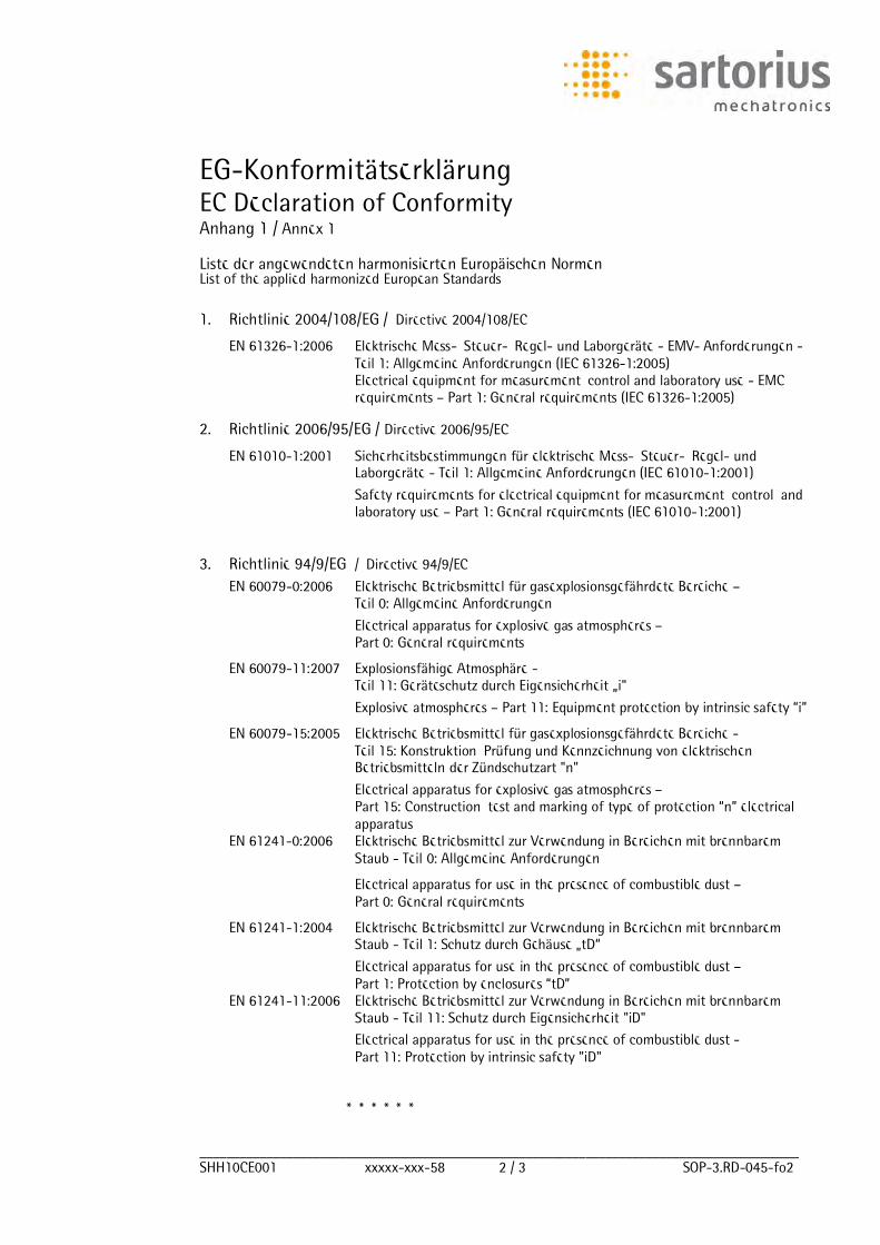
EG-KonformitätserklärungEC Declaration of Conformity
__________________________________________________________________________________________SHH10CE001 xxxxx-xxx-58 2 / 3 SOP-3.RD-045-fo2
Anhang 1 / Annex 1
Liste der angewendeten harmonisierten Europäischen NormenList of the applied harmonized European Standards
1. Richtlinie 2004/108/EG / Directive 2004/108/EC
EN 61326-1:2006 Elektrische Mess-, Steuer-, Regel- und Laborgeräte - EMV- Anforderungen -Teil 1: Allgemeine Anforderungen (IEC 61326-1:2005)Electrical equipment for measurement, control and laboratory use - EMCrequirements Part 1: General requirements (IEC 61326-1:2005)
2. Richtlinie 2006/95/EG / Directive 2006/95/EC
EN 61010-1:2001 Sicherheitsbestimmungen für elektrische Mess-, Steuer-, Regel- undLaborgeräte - Teil 1: Allgemeine Anforderungen (IEC 61010-1:2001)
Safety requirements for electrical equipment for measurement, control, andlaboratory use Part 1: General requirements (IEC 61010-1:2001)
3. Richtlinie 94/9/EG / Directive 94/9/EC
EN 60079-0:2006 Elektrische Betriebsmittel für gasexplosionsgefährdete Bereiche Teil 0: Allgemeine Anforderungen
Electrical apparatus for explosive gas atmospheres Part 0: General requirements
EN 60079-11:2007 Explosionsfähige Atmosphäre -Teil 11: Geräteschutz durch Eigensicherheit i"
Explosive atmospheres Part 11: Equipment protection by intrinsic safety i
EN 60079-15:2005 Elektrische Betriebsmittel für gasexplosionsgefährdete Bereiche -Teil 15: Konstruktion, Prüfung und Kennzeichnung von elektrischenBetriebsmitteln der Zündschutzart "n"
Electrical apparatus for explosive gas atmospheres Part 15: Construction, test and marking of type of protection n electricalapparatus
EN 61241-0:2006 Elektrische Betriebsmittel zur Verwendung in Bereichen mit brennbaremStaub - Teil 0: Allgemeine Anforderungen
Electrical apparatus for use in the presence of combustible dust Part 0: General requirements
EN 61241-1:2004 Elektrische Betriebsmittel zur Verwendung in Bereichen mit brennbaremStaub - Teil 1: Schutz durch Gehäuse tD
Electrical apparatus for use in the presence of combustible dust Part 1: Protection by enclosures tD
EN 61241-11:2006 Elektrische Betriebsmittel zur Verwendung in Bereichen mit brennbaremStaub - Teil 11: Schutz durch Eigensicherheit "iD"
Electrical apparatus for use in the presence of combustible dust -Part 11: Protection by intrinsic safety "iD"
* * * * * *
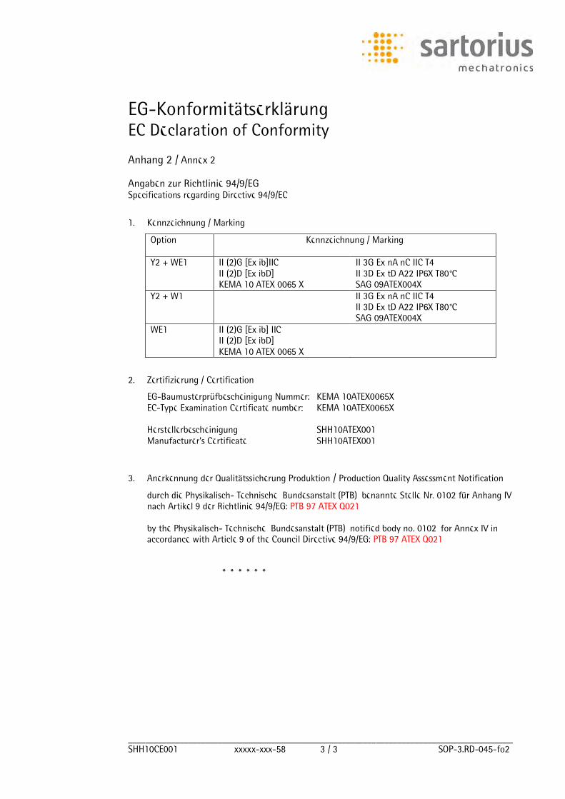
EG-KonformitätserklärungEC Declaration of Conformity
__________________________________________________________________________________________SHH10CE001 xxxxx-xxx-58 3 / 3 SOP-3.RD-045-fo2
Anhang 2 / Annex 2
Angaben zur Richtlinie 94/9/EGSpecifications regarding Directive 94/9/EC
1. Kennzeichnung / Marking
Option Kennzeichnung / Marking
Y2 + WE1 II (2)G [Ex ib]IICII (2)D [Ex ibD]KEMA 10 ATEX 0065 X
II 3G Ex nA nC IIC T4II 3D Ex tD A22 IP6X T80°CSAG 09ATEX004X
Y2 + W1 II 3G Ex nA nC IIC T4II 3D Ex tD A22 IP6X T80°CSAG 09ATEX004X
WE1 II (2)G [Ex ib] IICII (2)D [Ex ibD]KEMA 10 ATEX 0065 X
2. Zertifizierung / Certification
EG-Baumusterprüfbescheinigung Nummer: KEMA 10ATEX0065X EC-Type Examination Certificate number: KEMA 10ATEX0065X
Herstellerbescheinigung SHH10ATEX001 Manufacturer s Certificate SHH10ATEX001
3. Anerkennung der Qualitätssicherung Produktion / Production Quality Assessment Notification
durch die Physikalisch- Technische Bundesanstalt (PTB), benannte Stelle Nr. 0102 für Anhang IVnach Artikel 9 der Richtlinie 94/9/EG: PTB 97 ATEX Q021
by the Physikalisch- Technische Bundesanstalt (PTB), notified body no. 0102, for Annex IV inaccordance with Article 9 of the Council Directive 94/9/EG: PTB 97 ATEX Q021
* * * * * *


Sartorius Mechatronics T&H GmbH
Meiendorfer Straße 205
22145 Hamburg, Germany
Tel +49.40.67960.303
Fax: +49.40.67960.383
www.sartorius-mechatronics.com
Sartorius Mechatronics T&H GmbH
All rights are strictly reserved
Printed in Germany