transmission modelling data requirements - aeso modelling data requirements revision 0 tuesday 29...
TRANSCRIPT

Transmission Modelling Data Requirements
Revision 0
Tuesday 29 April 2003
Prepared by:
The Transmission Data Working Group Contributing Members Pamela Mclean P. Eng. Kevin Berg P. Eng. Ligong Gan, P. Eng. Lance Grainger P. Eng., Ph. D. Wenyan Gu, P. Eng., Ph.D. Sam Malik P. Eng Nigel Pimblet, P. Eng. Tony Rutkunas P. Eng.
The Transmission Data Working Group wishes to recognize the contributions of Mr. Rasheek Rifaat, P.Eng., who also contributed significantly to this report.
Transmission Modelling Data Requirements Revision 0
Alberta Electric System Operator i
\\aeso.ca\dfs\Technical\te\03\97\04\TransmissionModellingDataRequirements_R0d.doc Printed by:James Fietz Last Saved 2005-06-01 15:02
Executive Summary
This document outlines what data Facility Owners must submit to the Alberta Electric System Operator.
This document describes in detail the form or forms in which to submit data. Data submissions are to be complete, accurate and timely.

Transmission Modelling Data RequirementsRevision 0
Alberta Electric System Operator iii
\\aeso.ca\dfs\Technical\te\03\97\04\TransmissionModellingDataRequirements_R0d.doc Printed by:James Fietz Last Saved 2005-06-01 15:02
TABLE OF CONTENTS
EXECUTIVE SUMMARY I
1 SCOPE 7
2 BACKGROUND 7
3 ELECTRICAL PARAMETERS FOR TRANSMISSION OBJECTS 8
3.1 Load and Generation 8
3.1.1 Measurement Point 8
3.1.2 Bus-to-Measurement Point Mapping 8
3.1.3 Bus-to-Industry Mapping 8
3.1.4 Unmetered volumes 9
3.1.5 Load Forecast 10
3.2 Substations 11
3.2.1 Single Line Drawing; 12
3.3 Elements 13
3.4 Busses 13
3.5 Transformers 14
3.5.1 Transformer Windings 14
3.5.2 TransformerTerminations and Tapchangers 16
3.5.3 Transformer Impedances 17
3.6 Shunts 18
3.7 Transmission Lines 19
3.7.1 Transmission Line Structure Lists; 20

Transmission Modelling Data RequirementsRevision 0
Alberta Electric System Operator iv
\\aeso.ca\dfs\Technical\te\03\97\04\TransmissionModellingDataRequirements_R0d.doc Printed by:James Fietz Last Saved 2005-06-01 15:02
3.8 Line Segments 20
3.8.1 Line Segment Connectivity 20
3.8.2 Line Segments Construction 20
3.8.3 Line Mutual Data 24
3.9 Machines 25
3.9.1 Control System Data 27
3.9.2 PSS/E Model Data 28
3.10 Series Compensation 29
3.11 FACTS Devices 29
3.12 Supplementary Data 29
3.12.1 ProtectionTypes, and Application. 29
3.12.2 Historical Demand. 29
4 PROJECT PROCESS 30
APPENDIX I. DATA SUBMISSION FORMS 31
TABLE OF FIGURES
Figure 3.1-1 form MP_ID_DATA_Stage1 ................................................................................... 11
Figure 3.2-1 form Facilities_Stage1 ........................................................................................... 12
Figure 3.5-1 form Elements_Xformers_Stage1......................................................................... 18
Figure 3.6-1 form Elements_shunts_stage1 ............................................................................. 19
Figure 3.8-1 form Elements_Linesegements_Stage1 .............................................................. 24
Figure 3.8-2 form Mutuals_Stage1 ............................................................................................. 25
Figure 3.9-1 section 2 of form Elements_Sync_Machines_Char_Data .................................. 26
Figure 3.9-2 section 2 of form Elements_Induction_Machines_Char_Data .......................... 27

Transmission Modelling Data RequirementsRevision 0
Alberta Electric System Operator v
\\aeso.ca\dfs\Technical\te\03\97\04\TransmissionModellingDataRequirements_R0d.doc Printed by:James Fietz Last Saved 2005-06-01 15:02
Figure 3.9-3 section 2 of form Elements_Induction_Machines_Char_Data .......................... 28
Figure 3.9-3 section 2 of form Machine Dynamic Modelling Data Form ................................ 29
TABLES
Table 3.1-1 Standard Industry Types........................................................................................... 9
Table 3.4-1 Standard Bus Ranges.............................................................................................. 14
Table 3.5-1 Standard Winding Codes ........................................................................................ 15
Table 3.5-2 Standard Transformer Rating Conditions............................................................. 15
Table 3.5-3 Standard Termination (Bushing) Codes................................................................ 16
Table 3.5-4 Standard Tap-changing Strategies ........................................................................ 17
Table 3.6-1 Standard Shunt-switching Strategies.................................................................... 19
Table 3.8-1 Standard Conductors .............................................................................................. 21
Table 3.8-2 Standard Towers...................................................................................................... 21
Table 3.8-3 Capacity-limiting Conditions ................................................................................. 23
Table 3.9-1 StandardControl System Types ............................................................................. 27


Transmission Modelling Data RequirementsRevision 0
Alberta Electric System Operator vii
\\aeso.ca\dfs\Technical\te\03\97\04\TransmissionModellingDataRequirements_R0d.doc Printed by:James Fietz Last Saved 2005-06-01 15:02
1 Scope
This document outlines what data Facility Owners must submit to the Alberta Electric System Operator, in order to meet the medium term goals described in the Transmission Data Working Group (TDWG) Terms of Reference as assigned by the Transmission Planning Committee (TPC).
This document describes in detail the form or forms in which to submit data. Data submissions are to be complete, accurate and timely.
The Alberta Electric System Operator maintains an object-model of the transmission system, TASMo, which supports asset management; and powerflow, short-circuit and transient analysis data. The model does not, for the foreseeable future, require any new bulk data submissions. Instead, the model will be incrementally updated and improved by individual data submission related to representation log resolution or incorporation of new projects. It will be protected from new data discrepancies by strict adherance to the forms specified in this document.
As new projects are added to the physical transmission system, the data representing those projects will be added to the legacy data in TASMo.
2 Background
The Alberta Electric System Operator maintains an object-model of the transmission system, TASMo, which supports asset management; and powerflow, short-circuit and transient analysis data. TASMo was populated in 1998 and 1999 from legacy data compiled from multiple sources. The sources from which TASMo was populated had varying degrees of authority and detail and may include various deficiencies. As deficiencies are identified in the TASMo representation of the electric grid, a "representation log item" is created and forwarded to the TFO whose equipment is in question. The TFO is then responsible to resubmit information for that facility or element in a form compliant with this document.
The model presently in TASMo includes impedance data which is adequate for transmission system planning studies using loadflow, short circuit and dynamics, when applied appropriately by a skilled planning engineer. It also includes object data which has been reported inconsistently, notably
• Open circuit and short circuit test data is missing or incomplete for a majority of transformers.
• Line lengths, tower-types and configurations, and conductor types have been reported inconsistently.
• Switching strategy for shunt devices, in particular the voltage control bands, are suspect.
8
\\aeso.ca\dfs\Technical\te\03\97\04\TransmissionModellingDataRequirements_R0d.doc Printed by:James Fietz Last Saved 2005-06-01 15:02
3 Electrical Parameters for Transmission Objects
3.1 Load and Generation
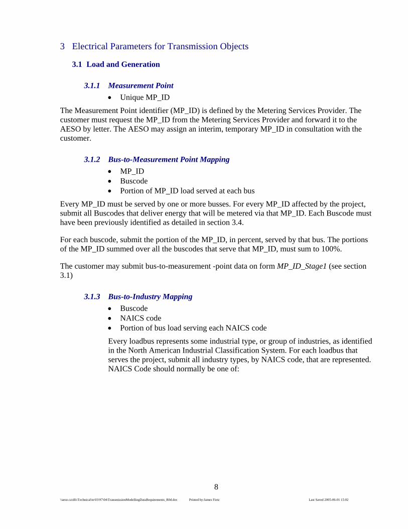
3.1.1 Measurement Point • Unique MP_ID
The Measurement Point identifier (MP_ID) is defined by the Metering Services Provider. The customer must request the MP_ID from the Metering Services Provider and forward it to the AESO by letter. The AESO may assign an interim, temporary MP_ID in consultation with the customer.
3.1.2 Bus-to-Measurement Point Mapping • MP_ID • Buscode • Portion of MP_ID load served at each bus
Every MP_ID must be served by one or more busses. For every MP_ID affected by the project, submit all Buscodes that deliver energy that will be metered via that MP_ID. Each Buscode must have been previously identified as detailed in section 3.4.
For each buscode, submit the portion of the MP_ID, in percent, served by that bus. The portions of the MP_ID summed over all the buscodes that serve that MP_ID, must sum to 100%.
The customer may submit bus-to-measurement -point data on form MP_ID_Stage1 (see section 3.1)
3.1.3 Bus-to-Industry Mapping • Buscode • NAICS code • Portion of bus load serving each NAICS code
Every loadbus represents some industrial type, or group of industries, as identified in the North American Industrial Classification System. For each loadbus that serves the project, submit all industry types, by NAICS code, that are represented. NAICS Code should normally be one of:

9
\\aeso.ca\dfs\Technical\te\03\97\04\TransmissionModellingDataRequirements_R0d.doc Printed by:James Fietz Last Saved 2005-06-01 15:02
Table 3.1-1 Standard Industry Types
NAICS CO INDUSTRY DESCR71 Arts, Entertainment and Recreation814 Private Households211 Oil And Gas Extraction32 Manufacturing - general33 Heavy Manufacturing40 Commercial and Services (except Pipelines and Private
Households) 113 Forestry and Logging11 Agriculture (except forestry, logging, and irrigation) 22131 Farming - Irrigation486 PipelinesFor other industries, contact the AESO.
For each industry, submit the portion of the bus, in percent, that represents that industry. by that bus. The portions of the bus summed over all the industries served by that bus, must sum to 100%.
The customer may submit bus-to-industry data on form MP_ID_Stage1 (see section 3.1)
3.1.4 Unmetered volumes • Buscode • Volume Type code • Unmetered Volume MW • In-service project and sub-project • Out-service project and sub-project (if known)
Unmetered volumes represent energy generated and used on site, that does not flow through MP_ID metering. Both unmetered load, and unmetered generation, must be submitted.
Submit all buscodes at which unmetered energy is either generated or used.
For each such bus, submit a code indicating whether the unmetered energy is generation (GEN) or (LOD). If unmetered energy is both generated and used at the same bus, submit two records for that bus.
Submit the normal volume, in MW, of unmetered energy of the designated type at each bus. Over all busses within the project, the total unmetered generation must equal the total load.
The project and sub-project identifier for the project that will bring the unmetered energy online must be entered in the "In" columns. If a subsequent project is identified that will remove the unmetered energy, that project and sub-project

10
\\aeso.ca\dfs\Technical\te\03\97\04\TransmissionModellingDataRequirements_R0d.doc Printed by:James Fietz Last Saved 2005-06-01 15:02
should be entered in the "Out" columns. Total unmetered generation must equal total load for all conditions of staged project implementation.
The customer may submit unmetered volume data on form MP_ID_Stage1 (see section 3.1)
3.1.5 Load Forecast • MP_ID • Volume Type code • Inservice Date • Outservicedate • Metered MW • Metered MVAr
The Load forecast represents future metered volumes of energy that does will flow through MP_ID metering. For every MP_ID affected by the project, identify whether the volumes measured will be Load (LOD) or Generation (GEN).
Submit the date range (Inservicedate to Outservice date) over which the forecast volume applies. If future increments in load or generation are anticipated, submit multiple records with non-overlapping dates.
For each MP_ID for each date-range submitted, submit the anticipated MW and MVAr.
The customer may submit forecast metered volume data on form MP_ID_DATA_Stage1 (see section 3.1)

11
\\aeso.ca\dfs\Technical\te\03\97\04\TransmissionModellingDataRequirements_R0d.doc Printed by:James Fietz Last Saved 2005-06-01 15:02
Figure 3.1-1 form MP_ID_DATA_Stage1
3.2 Substations
Submit a copy of the Single Line Diagram for the substation.
In addition, submit in the required format:
• Substation name • land location
Every Substation will have a unique identifier assigned by the AESO. The identifier shall consist of up to twenty characters including only Capital letters, the digits 0 through 9, period and hyphen. The proponent may request a particular identifier. Preferred identifiers are a simple, pronounceable, unambiguous word; or a short number optionally combined with a letter or letters.

12
\\aeso.ca\dfs\Technical\te\03\97\04\TransmissionModellingDataRequirements_R0d.doc Printed by:James Fietz Last Saved 2005-06-01 15:02
For Example: ROSSDALE
D05
Substation names are required only where the TFO in fact assigns names to their substations. The AESO will, upon request, provide assistance in selecting a substation name. Substation names should not include corporate names or variations on geographical names that are already used for other substations
Land locations shall be specified using the Dominion Land Survey designations specifying at minimum resolution the quarter-section, and preferably the Legal Sub-Division. Land locations shall conform rigourously to the following format: XX-XX-XX-XXWX.
The TFO may submit Substation data on Section 1 of form Facilities_Stage1 (see section 3.2)
Figure 3.2-1 form Facilities_Stage1
3.2.1 Single Line Drawing;
The Alberta Electric System Operator shall be sent a copy of a Single Line Diagram every time the Single Line Diagram is updated or altered. Submission may be by a copy of the paper diagram, but an electronic diagram is preferred.

13
\\aeso.ca\dfs\Technical\te\03\97\04\TransmissionModellingDataRequirements_R0d.doc Printed by:James Fietz Last Saved 2005-06-01 15:02
Electronic diagrams may be submitted in PNG, PDF, JPG, AutoCAD, Visio or CGM files.
3.3 Elements
• Submit in required format • Element type code (L, X, M, C) • Element normal in-service status • In-service project and sub-project • Out-service project and sub-project (if known)
Every Element will have a unique identifier assigned by the AESO. The identifier shall consist of up to twenty characters including only Capital letters, the digits 0 through 9, period and hyphen. The proponent may request a particular identifier. Preferred identifiers are a simple, pronounceable, unambiguous word; or a short number optionally combined with a letter or letters.
Element types are line-segments (L), transformers(X), machines (M -- includes both motors and generators) and shunts (C -- includes both capacitors and reactors).
Elements that are installed as standby equipment should have their "Normally in-Service" flag left blank; elements that are normally energized and functioning should have the flag ticked.
The project and sub-project identifier for the project that will initially install the element must be entered in the "In" columns. If a subsequent project is identified that will remove the element, that project and sub-project should be entered in the "Out" columns.
The TFO shall submit Element data on form Elements_Machines_Stage1 (see section 3.9), Elements_Linesegments_Stage1 (see section 3.7), Elements Shunts_Stage1 (see section 3.6), or Elements_Xformers_Stage1 (see section 3.5)
3.4 Busses
• Unique bus number, nominal bus voltage, and area code
New busses are identified by the AESO early in the System Access process, prior to any direct assign or RFP taking place. The AESO shall assign bus numbers shall be consistent with the following:

14
\\aeso.ca\dfs\Technical\te\03\97\04\TransmissionModellingDataRequirements_R0d.doc Printed by:James Fietz Last Saved 2005-06-01 15:02
Table 3.4-1 Standard Bus Ranges BUSRANGE BUSRANGE_DESCRIPTION From To
1 799 General transmission busses 1000 1999 2000 4999 15000 19999 20001 29999 30000 39999
Distribution busses
40000 49999 5000 8999 Transformer midpoint busses 10000 14999
Temporary busses 9000 9999 Unassigned 50000 99999
New bus numbering will generally follow the pattern used by existing busses in the same area. Nominal bus voltage on the transmission system shall be one of 240kV, 138kV, or 69kV. Distribution bus nominals shall be established in consultation with the Distribution Facility Owner. Facility owners must be aware that the operating voltage of the transmission system at any location may be higher or lower than the nominal voltage by several percent. Facility Owners are responsible to become aware of the operating characteristics of the transmission system at their point or points of interconnection, and to provide properly rated equipment.
The Alberta Electric System Operator will assign an Area Code according to the planning needs of the Alberta Interconnected Electric System.
When the ownership of the bus is assigned to a TFO, that TFO may assign an area number to it appropriate to their business requirements. The TFO may request the Alberta ElectricSystem Operator to add that bus to the “Pre-Restructuring Areas” table.
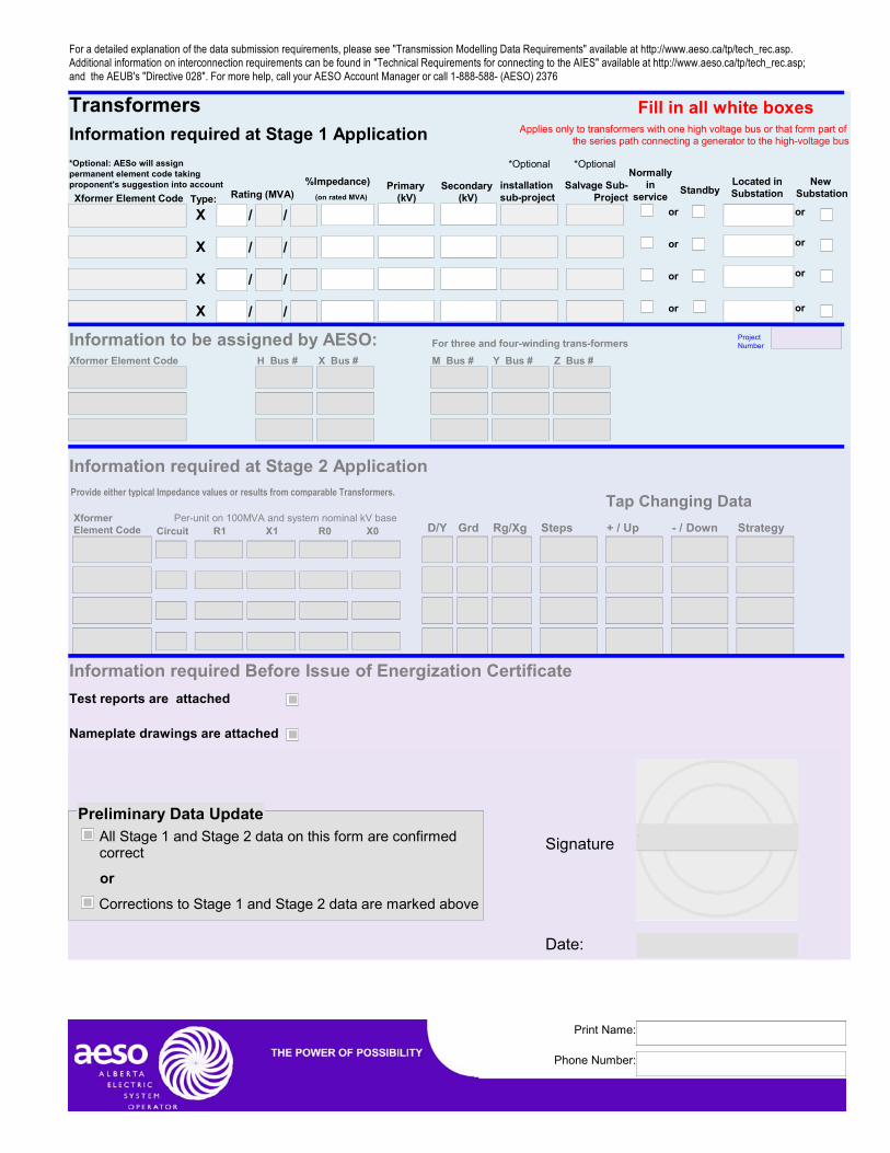
3.5 Transformers
Submit the transformer nameplate and test report.
Transformers have significant scope for variation from one transformer to the next. The data is requested in a standard format that can accommodate both common transformers and their variations; and more unusual transformers.
3.5.1 Transformer Windings
In addition to the nameplate and test report, submit in the required format:
• Winding identifier (P,S,T,Q) • connection(delta/wye) • grounding impedance • Ratings
Each winding must be identified with a standard winding-code. An auto-transformer is considered to be a single winding with two terminations. For
15
\\aeso.ca\dfs\Technical\te\03\97\04\TransmissionModellingDataRequirements_R0d.doc Printed by:James Fietz Last Saved 2005-06-01 15:02
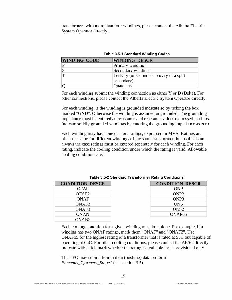
transformers with more than four windings, please contact the Alberta Electric System Operator directly.
Table 3.5-1 Standard Winding Codes WINDING CODE WINDING DESCRP Primary windingS Secondary windingT Tertiary (or second secondary of a split
secondary)Q QuatenaryFor each winding submit the winding connection as either Y or D (Delta). For other connections, please contact the Alberta Electric System Operator directly.
For each winding, if the winding is grounded indicate so by ticking the box marked "GND". Otherwise the winding is assumed ungrounded. The grounding impedance must be entered as resistance and reactance values expressed in ohms. Indicate solidly grounded windings by entering the grounding impedance as zero.
Each winding may have one or more ratings, expressed in MVA. Ratings are often the same for different windings of the same transformer, but as this is not always the case ratings must be entered separately for each winding. For each rating, indicate the cooling condition under which the rating is valid. Allowable cooling conditions are:
Table 3.5-2 Standard Transformer Rating Conditions CONDITION DESCR
OFAF OFAF2 ONAF ONAF2 ONAF3 ONAN ONAN2
CONDITION DESCRONP ONP2 ONP3 ONS ONS2
ONAF65
Each cooling condition for a given winding must be unique. For example, if a winding has two ONAF ratings, mark them "ONAF" and "ONAF2". Use ONAF65 for the highest rating of a transformer that is rated at 55C but capable of operating at 65C. For other cooling conditions, please contact the AESO directly. Indicate with a tick mark whether the rating is available, or is provisional only.
The TFO may submit termination (bushing) data on form Elements_Xformers_Stage1 (see section 3.5)
16
\\aeso.ca\dfs\Technical\te\03\97\04\TransmissionModellingDataRequirements_R0d.doc Printed by:James Fietz Last Saved 2005-06-01 15:02
3.5.2 TransformerTerminations and Tapchangers
In addition to the nameplate and test report, submit in the required format:
• terminal identifier(H,M,X,Y,Z), • tap points • tapchanging strategy (manual, automatic, settings) • rated voltage • bus to which terminal connects for every terminal
Windings may have one or more termination (bushing). Each termination must be identified by a standard termination code:
Table 3.5-3 Standard Termination (Bushing) Codes BUSHING CODE BUSHING DESCR
M Midpoint, virtual or internal "bushing" X Low-voltage bushingY Tertiary-voltage bushingZ Quatenary-voltage bushingH High-voltage bushing
List the terminations (bushings) under the winding on which the termination is made. A winding may have zero, one, or more terminations.
For each termination, enter the bus to which the termination is connected. If it is not connected, the bus may be left blank. Enter the rated voltage of that termination (also called the "rated winding voltage"). Note that in some cases this may be different from the nominal voltage of the bus to which the termination connects: in Alberta 145kV transformer terminations are routinely connected to the nominally 138kV grid.
A termination may be associated with a tap-changer. Enter the tap-changer maximum and minimum ratios in per-unit of the bushing rated voltage. For example, a plus-and-minus-ten-percent tap changer would have MaxTap of 1.1 and MinTap of 0.9. If no tap-changer exists for this termination, enter 1 for both MaxTap and MinTap. Enter the number of taps, including the nominal tap position. For example, plus-and-minus eight steps would be 17 taps. If no tap changer exists, enter 1 for Ntap. Enter the actual tap for fixed tap terminations. For tap-changer terminations, leave the Actual Tap field null.
Enter the Tap-changing strategy, one of:
17
\\aeso.ca\dfs\Technical\te\03\97\04\TransmissionModellingDataRequirements_R0d.doc Printed by:James Fietz Last Saved 2005-06-01 15:02
Table 3.5-4 Standard Tap-changing Strategies TAP CHAN TAP CHANGING DESCR OFF Off-load tap changingOLTC-M On-load tap changing (manual) OLTC-S On-load tap changing (supervisory) OLTC-A On-load tap changing (automatic) FIXED Fixed taps
• Enter which transformer termination is controlled by the tapchanging action -- usually the "X" bushing of a distribution load transformer. If a remote bus is controlled, enter the bus number. Enter the voltage range for tap-changer control, in per-unit of the system nominal voltage.
The TFO may submit termination (bushing) data on form Elements_Xformers_Stage1 (see section 3.5)
3.5.3 Transformer Impedances
In addition to the nameplate and test report, submit in the required format:
• Open circuit and short circuit test data • positive, negative and zero sequence resistance and reactance • phase shift, between highest voltage terminal and all other terminals;
Impedances must be expressed as the impedance between pairs of bushings which were previously defined. Where necessary, a midpoint bushing should be defined that allows radial impedances to be entered for multi-bushing transformers. An arbitrary two-character circuit identifier must be declared for each impedance branch. The circuit identifier should reflect the TFO's transformer numbering, for example "T2".
Enter Positive and Zero-sequence branch impedances in per-unit expressed on 100MVA base and the system nominal voltage of the bus connected to the un-tapped (or least responsively tapped) winding. For example, if the X bushing has OLTC and is connected to a 25kVnominal bus, and the Y bushing has off-load taps and is connected to a 138kV bus, express the branch impedance on 138kV and 100MVA, even if the transformer itself is rated 144/25kV. For most transformers, magnetizing branches are negligible: enter zero.
Enter copperloss and coreloss directly from the transformer test report in kva. Enter excitation current. Usually only one short-circuit test is performed for each pair of windings, but space is given to enter redundant tests if such were performed. Transformer test report must be appended to this form.
Test data may be available on more than one base. The test data submitted should be for performed on the nominal tap position, where available. The TFO may submit Transformer data on form Elements_Xformers_Stage1 (see section 3.5)
18
\\aeso.ca\dfs\Technical\te\03\97\04\TransmissionModellingDataRequirements_R0d.doc Printed by:James Fietz Last Saved 2005-06-01 15:02
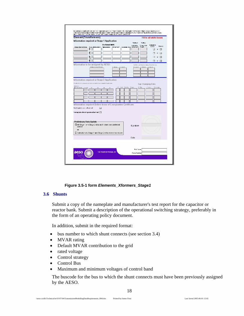
Figure 3.5-1 form Elements_Xformers_Stage1
3.6 Shunts
Submit a copy of the nameplate and manufacturer's test report for the capacitor or reactor bank. Submit a description of the operational switching strategy, preferably in the form of an operating policy document.
In addition, submit in the required format:
• bus number to which shunt connects (see section 3.4) • MVAR rating • Default MVAR contribution to the grid • rated voltage • Control strategy • Control Bus • Maximum and minimum voltages of control band
The buscode for the bus to which the shunt connects must have been previously assigned by the AESO.

19
\\aeso.ca\dfs\Technical\te\03\97\04\TransmissionModellingDataRequirements_R0d.doc Printed by:James Fietz Last Saved 2005-06-01 15:02
Default MVAR contribution to the grid must be either 0, or the MVAR rating of the shunt, depending on whether the shunt is normally switched in, or normally switched out.
The Control Strategy must be one of
Table 3.6-1 Standard Shunt-switching Strategies CODE StrategyM ManualS SupervisoryA AutomaticF Fixed
Enter the Bus at which the voltage is monitored for the purpose of controlling this shunt device. Enter the maximum and minimum voltages of the control band, in per-unit of the system nominal kV at the controlled bus.
The TFO may submit Shunt data on form Elements_shunts_stage1 (see section 3.6)
Figure 3.6-1 form Elements_shunts_stage1
3.7 Transmission Lines
Submit a copy of the Structure List or Line Survey for the Line.
20
\\aeso.ca\dfs\Technical\te\03\97\04\TransmissionModellingDataRequirements_R0d.doc Printed by:James Fietz Last Saved 2005-06-01 15:02
Submit a dimensioned drawing of every tower-type mentioned on the Structure List.
Every Line will have a unique identifier assigned by the AESO. The identifier shall consist of up to twenty characters including only Capital letters, the digits 0 through 9, period and hyphen. The proponent may request a particular identifier. Preferred identifiers are a simple strings of numbers incorporating the letter "L".
For Example: 9L48
162L
The TFO may submit Transmission Line data on Section 1 of form Facilities_Stage1 (see section 3.1)
3.7.1 Transmission Line Structure Lists;
The Alberta Electric System Operator shall be sent a copy of a Structure List every time the Structure list is updated or altered. Submission may be by a copy of the paper list, but an electronic list in text form or PDF is preferred. If a new tower type is introduced into a structure list, submit a dimensioned drawing of the tower type.
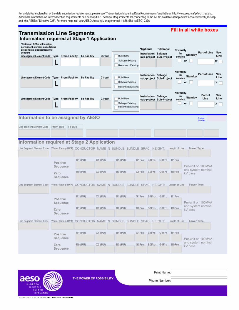
3.8 Line Segments
3.8.1 Line Segment Connectivity
Line segment connectivity shall be expressed as "From Bus, To Bus, Circuit Identifier". The From Bus and To bus must have been previously identified. Circuit identifiers are two-character strings and should be chosen in some way to reflect the unique identifier for the line.
Line segments with the same "From Bus" and "To Bus" and having the same Circuit Identifier are connected in series. Groups of line segments having the same "From Bus" and "To Bus" and different Circuit Identifiers are connected in parallel.
Line connectivity data will be submitted on form Elments_Linesegments_Stage1 (see section 3.8)
3.8.2 Line Segments Construction • conductor type • # of conductors per bundle • bundle spacing • average sag • tower type • tower height • line segment length • positive and zero-sequence real and reactive impedances

21
\\aeso.ca\dfs\Technical\te\03\97\04\TransmissionModellingDataRequirements_R0d.doc Printed by:James Fietz Last Saved 2005-06-01 15:02
• positive and zero-sequence real and reactive shunt admittance
The conductor type must be previously defined by the AESO. It should normally be one of:
Table 3.8-1 Standard Conductors
CONDUCTOR NAME CHICKADEE COCHIN COREOPSIS COSMOS CROWSNEST CURLEW DOVE DRAKE HADDOCK HAWK HORNBILL IBIS
CONDUCTOR NAME LINNETMERLINOSPREYPARTRIDGEPELICANPENGUINPIGEONRAVENSPARROWTRILLIUMWAXWING
Contact the AESO prior to using a different conductor.
Express the bundle spacing in meters.
The tower type must be previously defined by the AESO. It should normally be one of:
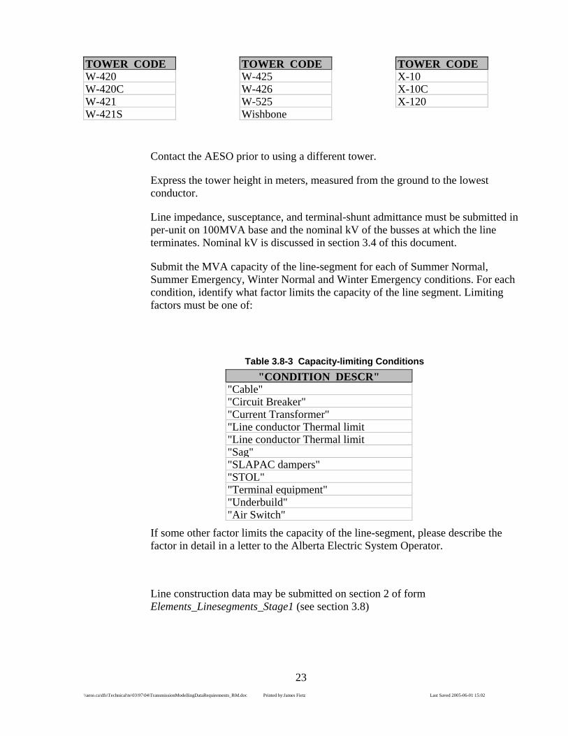
Table 3.8-2 Standard Towers TOWER CODE 2016-4 350152 350153 350172 350353 350355 353152 370102 370105 370116 370118
TOWER CODE370119370125370126370214370220370306370310370312370319370336370367
TOWER CODE371102 373102 373319 377102 390102 5005-5 5015-5 5102-7 5105-5 5110-7 5112-7

22
\\aeso.ca\dfs\Technical\te\03\97\04\TransmissionModellingDataRequirements_R0d.doc Printed by:James Fietz Last Saved 2005-06-01 15:02
TOWER CODE 51127S 5114-7 5126-7 5132-7 5138-7 5138-9 5140-7 5140-9 5142-7 5144-7 5144-9 5148-7 5156-7 51567S 5172-7 5251-7 5308-5 5310-7 53109 5311-7 5316-7 5317-7 5318-7 53227S 5328-7 5329-5 5329-7 5334-7 5340-7 5344-5 5348-7 5352-5 5368-7 5368-9 5369-9 5373-9 53787S A-31 A-TOWR A1 A1A A2 A21 A21A A21B A2A A31A
TOWER CODEA31BA41A41AAPLB1AB2B2AC-TOWRC1C1ACO1091CO325BCableD-1D-11D1D1ADeltaF-7F1F21Frame201AFrame201BFrame203Frame204Frame209Frame251Frame252Frame253Frame255AFrame255BFrame256Frame257Frame268Frame270Frame276FrameCP69FrameF1FFrameF20FrameF21FrameS273-CG-TOWRG1G22GC-TWRGJ-TWRH-FRAM
TOWER CODEH-Frame ATCOH-Frame ENMAXH-Frame-M H10A K-500 K-500s K1 KA-TWR L L-TOWER ATCOL-TOWER L-TOWER TAULETHBR M-TOWER MH94-710100N-TOWER N1 O-TOWR Q-Q Q-TOWR R R-TOWR S-TAN S-TOWR S273-C S53489 SK2016 SYNTAN T-TANGENTT-TOWER T-W-421 T1 TGA TSA TYP.GU TYP270 Tangent105 Tangent35 Tangent48 Tangent88 Tower56 Tower71 W-1500 W-1600 W-1700 W-200 W-415
23
\\aeso.ca\dfs\Technical\te\03\97\04\TransmissionModellingDataRequirements_R0d.doc Printed by:James Fietz Last Saved 2005-06-01 15:02
TOWER CODE W-420 W-420C W-421 W-421S
TOWER CODEW-425W-426W-525Wishbone
TOWER CODEX-10 X-10C X-120
Contact the AESO prior to using a different tower.
Express the tower height in meters, measured from the ground to the lowest conductor.
Line impedance, susceptance, and terminal-shunt admittance must be submitted in per-unit on 100MVA base and the nominal kV of the busses at which the line terminates. Nominal kV is discussed in section 3.4 of this document.
Submit the MVA capacity of the line-segment for each of Summer Normal, Summer Emergency, Winter Normal and Winter Emergency conditions. For each condition, identify what factor limits the capacity of the line segment. Limiting factors must be one of:
Table 3.8-3 Capacity-limiting Conditions "CONDITION DESCR"
"Cable""Circuit Breaker""Current Transformer""Line conductor Thermal limit "Line conductor Thermal limit "Sag""SLAPAC dampers""STOL""Terminal equipment""Underbuild""Air Switch"
If some other factor limits the capacity of the line-segment, please describe the factor in detail in a letter to the Alberta Electric System Operator.
Line construction data may be submitted on section 2 of form Elements_Linesegments_Stage1 (see section 3.8)

24
\\aeso.ca\dfs\Technical\te\03\97\04\TransmissionModellingDataRequirements_R0d.doc Printed by:James Fietz Last Saved 2005-06-01 15:02
Figure 3.8-1 form Elements_Linesegements_Stage1
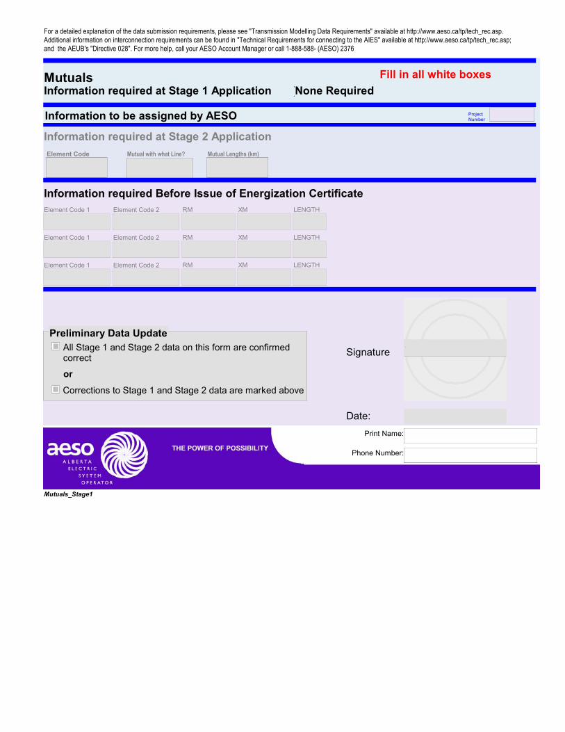
3.8.3 Line Mutual Data
Where a transmission line parallels another transmission line for 50km or more, submit the mutual impedance coupling between the two lines. Mutual impedance must be submitted in per-unit on 100MVA base and the nominal kV of the busses at which the line terminates. Nominal kV is discussed in section 3.4 of this document.
Line construction data may be submitted on section 2 of form Mutuals_Stage1. (see section 3.8.3)

25
\\aeso.ca\dfs\Technical\te\03\97\04\TransmissionModellingDataRequirements_R0d.doc Printed by:James Fietz Last Saved 2005-06-01 15:02
Figure 3.8-2 form Mutuals_Stage1
3.9 Machines
Submit a WECC-compliant test report of each machine and all associated control systems. Submit nameplate and manufacturer's data for each machine.
In addition, for each machine, submit
• the bus to which the machine is interconnected • a code identifying the machine as either a motor or a generator
The buscode for the bus to which the machine is interconnected must have been previously assigned by the AESO.
Nameplate and manufacturers data must include at a minimum:
• The machine base MVA • The machine base kV • Maximum continuous rating in MW • Emergency continuous rating in MW • Minimum stable generation in MW • Maximum reactive power generation capability in MVAr

26
\\aeso.ca\dfs\Technical\te\03\97\04\TransmissionModellingDataRequirements_R0d.doc Printed by:James Fietz Last Saved 2005-06-01 15:02
• Maximum reactive power absorption capability in MVAr (as a negative number) • Machine Inertia constant • Machine positive-sequence subtransient reactance in per-unit on machine base MVA • Machine positive-sequence subsynchronous reactance in per-unit on machine base
MVA • Machine positive-sequence synchronous reactance in per-unit on machine base MVA • Machine zero-sequence per-unit resistance on Machine base MVA and kV • Machine zero-sequence per-unit synchronous reactance on Machine base MVA and
kV • House Load, in MW, being the power consumed by the generating plant directly
related to generation: i.e. coal crushers, water pumps, et cetera
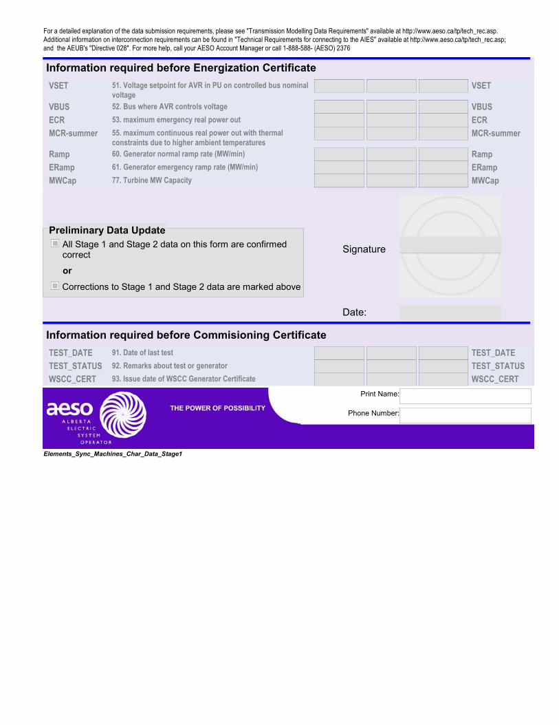
The TFO may submit synchronous machine nameplate data on form Elements_Sync_Machines_Char_Data (see section 3.9).
Figure 3.9-1 section 2 of form Elements_Sync_Machines_Char_Data
The TFO may submit induction machine nameplate data on form Elements_Induction_Machines_Char_Data (see section 3.9).

27
\\aeso.ca\dfs\Technical\te\03\97\04\TransmissionModellingDataRequirements_R0d.doc Printed by:James Fietz Last Saved 2005-06-01 15:02
Figure 3.9-2 section 2 of form Elements_Induction_Machines_Char_Data
3.9.1 Control System Data
List each control system with a description of its manufacturer, make and model. Control Systems must be one of:
Table 3.9-1 StandardControl System Types CONTROL SYSCompensatorExciterExciter LimiterGeneratorLoadStabilizerTurbineGovernor
The TFO may submit Control System data on Section 1 of form Elements_Machines_Stage1 (see section 3.9).

28
\\aeso.ca\dfs\Technical\te\03\97\04\TransmissionModellingDataRequirements_R0d.doc Printed by:James Fietz Last Saved 2005-06-01 15:02
Figure 3.9-3 section 2 of form Elements_Induction_Machines_Char_Data
3.9.2 PSS/E Model Data
A requirement of the WECC-compliant test report is a PSS/E model representing the action of each control system.
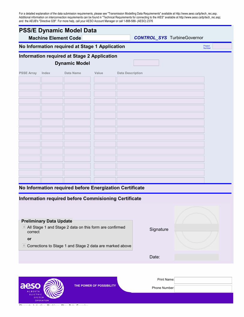
The TFO may submit Dynamic Machine data on form Machine Dynamic Modelling Data Form (see section 3.9).

29
\\aeso.ca\dfs\Technical\te\03\97\04\TransmissionModellingDataRequirements_R0d.doc Printed by:James Fietz Last Saved 2005-06-01 15:02
Figure 3.9-4 section 2 of form Machine Dynamic Modelling Data Form
3.10 Series Compensation
(This section will be written when a significant Series Compensation installation occurs)
3.11 FACTS Devices
(This section will be written when a significant FACTS installation occurs)
3.12 Supplementary Data
3.12.1 ProtectionTypes, and Application.
The AESO will request that settings will be provided, on a situational basis.
3.12.2 Historical Demand.
Historical demand is maintained by Metering Point in 15-minute intervals in the Alberta Electric System Operators metering and billing database. The owner of a Point of Delivery or Supply is responsible to ensure that correct data is reported to the Alberta Electric System Operator through the metering system, and that

30
\\aeso.ca\dfs\Technical\te\03\97\04\TransmissionModellingDataRequirements_R0d.doc Printed by:James Fietz Last Saved 2005-06-01 15:02
erroneous data is corrected. Accurate Point-of-Delivery and Point-of-Supply metering fulfills this data requirement.
4 Project Process
The System Access process is described on the AESO website at http://web.ta-alberta.ca/cs/SystemAccessProcessandTimelines_Color_REVISED1.pdf. The project process is initiated by submitting the Stage 1 System Access Application http://web.ta-alberta.ca/tar/Stage1Application-PrelimAssess-20030526.pdf. The Application must be accompanied by the MPID Data Stage 1 form, and forms for any customer-installed transmission equipment that will form part of the project; with the Stage 1 section of all data forms fully completed. If the project proceeds to Stage 2, and to Energization, additional data must be submitted at each stage. Receipt of the required data is acknowledged by the AESO when the Energization Certificate is issued. For generators, receipt of the final model validation test report is acknowledged by the AESO when the Commissioning Certificate is issued.
An Energization Certificate deficiency list is provided early in the project process, and will list deficiencies in data. Updates to the Energization Certificate deficiency list may be obtained by request, and will show when data deficiencies have been resolved. An Energization Certificate will not be issued until all data submissions are complete.

31
\\aeso.ca\dfs\Technical\te\03\97\04\TransmissionModellingDataRequirements_R0d.doc Printed by:James Fietz Last Saved 2005-06-01 15:02
APPENDIX I. DATA SUBMISSION FORMS


For a detailed explanation of the data submission requirements, please see "Transmission Modelling Data Requirements" available at http://www.aeso.ca/tp/tech_rec.asp. Additional information on interconnection requirements can be found in "Technical Requirements for connecting to the AIES" available at http://www.aeso.ca/tp/tech_rec.asp; and the AEUB's "Directive 028". For more help, call your AESO Account Manager or call 1-888-588- (AESO) 2376
MP_ID* DataInformation required at Stage 1 Application
Information assigned by AESO Working MP_ID
MP_ID Type
Area
Fill in all white boxesFor projects with more than one Measurement Point, use additional forms
Point of Delivery Point of Supplyor
Project Number
Information required at Stage 2 ApplicationBusNumber % NAICS % BusNumber % NAICS % BusNumber % NAICS %
Description of the MP_ID
Forecast Load/Generation in MW for the next 10 Years of Winter Peak2004 2005 2006 2007 2008 2009 2010 2011 2012 2013
Information required Before Issue of Energization Certificate
Final_MP_ID
Effective on Date
Expires on Date
Metering Service Provider
Signature
Date
MP_ID_DATA_Stage1
Phone Number:
Print Name:

For a detailed explanation of the data submission requirements, please see "Transmission Modelling Data Requirements" available at http://www.aeso.ca/tp/tech_rec.asp. Additional information on interconnection requirements can be found in "Technical Requirements for connecting to the AIES" available at http://www.aeso.ca/tp/tech_rec.asp; and the AEUB's "Directive 028". For more help, call your AESO Account Manager or call 1-888-588- (AESO) 2376
Substation (or Line) Facility Code:
Information assigned by AESO:
Buscode BusName kV AreaWECC-Full AIES-RED
Facility
Name Will be assigned by AESO if not provided or non-conformant
In-Service DateInformation required at Stage 1 Application
Owner of Substation
Out-Service Date *If applicable
Complete this portion only if you are building a
Land Location
LSD orQuadrant Section Township Range Meridian
*Optional
W
From (Substation or Line)
To (Substation or Line)
Similar existing construction
*Optional
Preliminary SLD is attached
Fill in all white boxes
Substation
Complete this portion only if you are building a
Transmission Line
A Facility is a Line or a Substation. Fill out a separate form for each facility you are building
Project Number
WECC-RED
Information required at Stage 2 Application
<See Machine, Transformer, Linesegment, shunt and Load forms>
Facilities Stage1
Phone Number:
Print Name:

For a detailed explanation of the data submission requirements, please see "Transmission Modelling Data Requirements" available at http://www.aeso.ca/tp/tech_rec.asp. Additional information on interconnection requirements can be found in "Technical Requirements for connecting to the AIES" available at http://www.aeso.ca/tp/tech_rec.asp; and the AEUB's "Directive 028". For more help, call your AESO Account Manager or call 1-888-588- (AESO) 2376
Information required Before Issue of Energization CertificateConstruction SLD is attached
Preliminary Data UpdateAll Stage 1 and Stage 2 data on this form are confirmed correct
Corrections to Stage 1 and Stage 2 data are marked above
or
Signature
Date:
.
Facilities_Stage1_2003-12-19
Phone Number:
Print Name:
For a detailed explanation of the data submission requirements, please see "Transmission Modelling Data Requirements" available at http://www.aeso.ca/tp/tech_rec.asp. Additional information on interconnection requirements can be found in "Technical Requirements for connecting to the AIES" available at http://www.aeso.ca/tp/tech_rec.asp; and the AEUB's "Directive 028". For more help, call your AESO Account Manager or call 1-888-588- (AESO) 2376
TransformersInformation required at Stage 1 Application
*Optional
Rating (MVA)Type:installation sub-project
%Impedance) Primary (kV)
Salvage Sub-ProjectXformer Element Code
Secondary (kV)
X
Fill in all white boxes
Normally in
service Standby
or
*Optional
X or
X or
X or
*Optional: AESo will assign permanent element code taking proponent's suggestion into account
Applies only to transformers with one high voltage bus or that form part of the series path connecting a generator to the high-voltage bus
(on rated MVA)
Located in Substation
New Substation
or
or
or
or
/
/
/
/
/
/
/
/
Information to be assigned by AESO: Xformer Element Code H Bus # X Bus # M Bus #
For three and four-winding trans-formersY Bus # Z Bus #
Project Number
Information required at Stage 2 Application
Tap Changing DataProvide either typical Impedance values or results from comparable Transformers.
R1 X1Xformer Element Code R0 X0Circuit + / Up - / Down StrategyD/Y Rg/XgGrd Steps
Per-unit on 100MVA and system nominal kV base
Information required Before Issue of Energization CertificateTest reports are attached
Nameplate drawings are attached
Preliminary Data UpdateAll Stage 1 and Stage 2 data on this form are confirmed correct
Corrections to Stage 1 and Stage 2 data are marked above
or
Signature
Date:
.
Phone Number:
Print Name:

For a detailed explanation of the data submission requirements, please see "Transmission Modelling Data Requirements" available at http://www.aeso.ca/tp/tech_rec.asp. Additional information on interconnection requirements can be found in "Technical Requirements for connecting to the AIES" available at http://www.aeso.ca/tp/tech_rec.asp; and the AEUB's "Directive 028". For more help, call your AESO Account Manager or call 1-888-588- (AESO) 2376
Elements_Xformers_Stage1
Phone Number:
Print Name:

For a detailed explanation of the data submission requirements, please see "Transmission Modelling Data Requirements" available at http://www.aeso.ca/tp/tech_rec.asp. Additional information on interconnection requirements can be found in "Technical Requirements for connecting to the AIES" available at http://www.aeso.ca/tp/tech_rec.asp; and the AEUB's "Directive 028". For more help, call your AESO Account Manager or call 1-888-588- (AESO) 2376
Transmission ShuntsInformation required at Stage 1 Application
Type:installation sub-project
Salvage Sub-ProjectShunt Element Code
CRating (MVA) RATED KV
Type:installation sub-project
Salvage Sub-ProjectShunt Element Code
CRating (MVA) RATED KV
Type:installation sub-project
Salvage Sub-ProjectShunt Element Code
CRating (MVA) RATED KV
Fill in all white boxes
Normally in service Standby
or
Normally in service Standby
or
Normally in service Standby
or
*optional *optional*Optional: AESo will assign permanent element code taking proponent's suggestion into account
(Applies only to shunt devices connected at the transmission voltage, or otherwise upstream of any POD/POS metering)
Located in Substation
New Substation
or
Located in Substation
New Substation
or
Located in Substation
New Substation
or
Information to be assigned by AESOElement Code Bus Index Element Code Bus Index Element Code Bus Index
Project Number
Information required at Stage 2 Application
Element CodeBus where voltage is controlled V_MAX: V_MIN: GROUNDED: GROUNDING_R: GROUNDING_X:Control Strategy
Element CodeBus where voltage is controlled V_MAX: V_MIN: GROUNDED: GROUNDING_R: GROUNDING_X:Control Strategy
Element CodeBus where voltage is controlled V_MAX: V_MIN: GROUNDED: GROUNDING_R: GROUNDING_X:Control Strategy
Information required Before Issue of Energization Certificate
Preliminary Data UpdateAll Stage 1 and Stage 2 data on this form are confirmed correct
Corrections to Stage 1 and Stage 2 data are marked above
or
Signature
Date:
.
Elements_Shunts_Stage1
Phone Number:
Print Name:
For a detailed explanation of the data submission requirements, please see "Transmission Modelling Data Requirements" available at http://www.aeso.ca/tp/tech_rec.asp. Additional information on interconnection requirements can be found in "Technical Requirements for connecting to the AIES" available at http://www.aeso.ca/tp/tech_rec.asp; and the AEUB's "Directive 028". For more help, call your AESO Account Manager or call 1-888-588- (AESO) 2376
Transmission Line SegmentsInformation required at Stage 1 Application
*Optional *Optional
Type:Installation sub-project
Salvage Sub-ProjectLinesegment Element Code
LTo Facility Circuit From Facility Build New
Salvage Existing
Reconnect Existing
Type:Installation sub-project
Salvage Sub-ProjectLinesegment Element Code
LTo Facility Circuit From Facility Build New
Salvage Existing
Reconnect Existing
Type:Installation sub-project
Salvage Sub-ProjectLinesegment Element Code
LTo Facility Circuit From Facility Build New
Salvage ExistingReconnect Existing
Fill in all white boxes
*Optional: AESo will assign permanent element code taking proponent's suggestion into account
Normally in
service Standby
or
Part of Line New Line
or
Normally in
service Standby
or
Part of Line New Line
or
Normally in
service Standby
or
Part of Line
New Line
or
Information to be assigned by AESO
From Bus To BusLine segment Element Code
Project Number
Information required at Stage 2 ApplicationWinter Rating (MVA) Length of Line Tower Type
R1 (PU) X1 (PU) B1 (PU) G1Fro
Line Segment Element Code
B1Fro G1Fro B1Fro
R0 (PU) X0 (PU) B0 (PU) G0Fro B0Fro G0Fro B0Fro
CONDUCTOR NAME N BUNDLE BUNDLE SPAC HEIGHT:
Winter Rating (MVA) Length of Line Tower Type
R1 (PU) X1 (PU) B1 (PU) G1Fro
Line Segment Element Code
B1Fro G1Fro B1Fro
R1 (PU) X0 (PU) B0 (PU) G0Fro B0Fro G0Fro B0Fro
CONDUCTOR NAME N BUNDLE BUNDLE SPAC HEIGHT:
Winter Rating (MVA) Length of Line Tower Type
R1 (PU) X1 (PU) B1 (PU) G1Fro
Line Segment Element Code
B1Fro G1Fro B1Fro
R0 (PU) X0 (PU) B0 (PU) G0Fro B0Fro G0Fro B0Fro
CONDUCTOR NAME N BUNDLE BUNDLE SPAC HEIGHT:
Positive Sequence
Zero Sequence
Positive Sequence
Zero Sequence
Positive Sequence
Zero Sequence
Per-unit on 100MVA and system nominal kV base
Per-unit on 100MVA and system nominal kV base
Per-unit on 100MVA and system nominal kV base
Elements Linesegments Stage1 20030911
Phone Number:
Print Name:

For a detailed explanation of the data submission requirements, please see "Transmission Modelling Data Requirements" available at http://www.aeso.ca/tp/tech_rec.asp. Additional information on interconnection requirements can be found in "Technical Requirements for connecting to the AIES" available at http://www.aeso.ca/tp/tech_rec.asp; and the AEUB's "Directive 028". For more help, call your AESO Account Manager or call 1-888-588- (AESO) 2376
Information required Before Issue of Energization Certificate
Transmission Line Data Summary attached
Structure List attached
Route Plan attached
Line Impedance Calculations attached
Attach suitable documentation to the form and check the boxes to indicate that the data is attached.
Preliminary Data UpdateAll Stage 1 and Stage 2 data on this form are confirmed correct
Corrections to Stage 1 and Stage 2 data are marked above
or
Signature
Date:
.
Elements_Linesegments_Stage1 20030911
Phone Number:
Print Name:
For a detailed explanation of the data submission requirements, please see "Transmission Modelling Data Requirements" available at http://www.aeso.ca/tp/tech_rec.asp. Additional information on interconnection requirements can be found in "Technical Requirements for connecting to the AIES" available at http://www.aeso.ca/tp/tech_rec.asp; and the AEUB's "Directive 028". For more help, call your AESO Account Manager or call 1-888-588- (AESO) 2376
MutualsInformation required at Stage 1 Application
Information to be assigned by AESO
(None RequiredFill in all white boxes
Project Number
Information required at Stage 2 ApplicationElement Code Mutual with what Line? Mutual Lengths (km)
Information required Before Issue of Energization CertificateElement Code 1 Element Code 2 RM XM LENGTH
Element Code 1 Element Code 2 RM XM LENGTH
Element Code 1 Element Code 2 RM XM LENGTH
Preliminary Data UpdateAll Stage 1 and Stage 2 data on this form are confirmed correct
Corrections to Stage 1 and Stage 2 data are marked above
or
Signature
Date:
.
Mutuals_Stage1
Phone Number:
Print Name:

For a detailed explanation of the data submission requirements, please see "Transmission Modelling Data Requirements" available at http://www.aeso.ca/tp/tech_rec.asp. Additional information on interconnection requirements can be found in "Technical Requirements for connecting to the AIES" available at http://www.aeso.ca/tp/tech_rec.asp; and the AEUB's "Directive 028". For more help, call your AESO Account Manager or call 1-888-588- (AESO) 2376
Machines Characteristic DataMachine Element Codes
Synchronous
Information required at Stage 1 Application Fill in all white boxes
Information required at Stage 2 Application
MCQ 05. maximum continuous reactive power out (MVAr) MCQP_MIN 06. minimum continuous real power out (MW) P_MINQ_MIN 07. minimum continuous reactive power out (MVAr) Q_MINHouseLoad 08. Power used directly to generate power. HouseLoadH 09. Inertia constant HX2 17. machine negative-sequence reactance on machine base
MVAX2
X0 18. machine zero-sequence reactance on machine base MVA X0XL 19. Flux linkage reactance XLR1 20. machine positive-sequence resistance on machine base
MVAR1
R2 21. machine negative-sequence resistance on machine base MVA
R2
R0 22. machine zero-sequence resistance on machine base MVA R0S(E1) 23. Saturation at reference voltage E1 S(E1)E1 24. Saturation reference voltage E1, normally rated voltage E1S(E2) 25. Saturation at reference voltage E2 S(E2)E2 26. Saturation reference voltage E2, normally 20% above
rated voltageE2
Fuel 29. Fuel or Energy Source FuelXD 31. machine positive-sequence synchronous reactance on
machine base MVAXD
X'D 32. machine positive-sequence subsynchronous reactance on machine base MVA
X'D
X"D 33. machine positive-sequence subtransient unsaturated reactance on machine base MVA
X"D
XQ 34. machine positive-sequence synchronous quadrature reactance on machine base MVA
XQ
X'Q 35. machine positive-sequence subsynchronous quadrature reactance on machine base MVA
X'Q
X"Q 36. machine positive-sequence subtransient unsaturated reactance on machine base MVA
X"Q
T'D0 37. Subsyncronous direct-axis open-circuit time constant T'D0T"D0 38. Subtransient direct-axis open-circuit time constant T"D0T'qo 39. Subsyncronous Quadrature-axis open-circuit time
constantT'qo
T"Q0 40. Subtransient Quadrature-axis open-circuit time constant T"Q0
Elements Sync Machines Char Data Stage1
Phone Number:
Print Name:
For a detailed explanation of the data submission requirements, please see "Transmission Modelling Data Requirements" available at http://www.aeso.ca/tp/tech_rec.asp. Additional information on interconnection requirements can be found in "Technical Requirements for connecting to the AIES" available at http://www.aeso.ca/tp/tech_rec.asp; and the AEUB's "Directive 028". For more help, call your AESO Account Manager or call 1-888-588- (AESO) 2376
Information required before Energization CertificateVSET 51. Voltage setpoint for AVR in PU on controlled bus nominal
voltageVSET
VBUS 52. Bus where AVR controls voltage VBUSECR 53. maximum emergency real power out ECRMCR-summer 55. maximum continuous real power out with thermal
constraints due to higher ambient temperaturesMCR-summer
Ramp 60. Generator normal ramp rate (MW/min) RampERamp 61. Generator emergency ramp rate (MW/min) ERampMWCap 77. Turbine MW Capacity MWCap
Preliminary Data UpdateAll Stage 1 and Stage 2 data on this form are confirmed correct
Corrections to Stage 1 and Stage 2 data are marked above
or
Signature
Date:
.
Information required before Commisioning CertificateTEST_DATE 91. Date of last test TEST_DATETEST_STATUS 92. Remarks about test or generator TEST_STATUSWSCC_CERT 93. Issue date of WSCC Generator Certificate WSCC_CERT
Elements_Sync_Machines_Char_Data_Stage1
Phone Number:
Print Name:

For a detailed explanation of the data submission requirements, please see "Transmission Modelling Data Requirements" available at http://www.aeso.ca/tp/tech_rec.asp. Additional information on interconnection requirements can be found in "Technical Requirements for connecting to the AIES" available at http://www.aeso.ca/tp/tech_rec.asp; and the AEUB's "Directive 028". For more help, call your AESO Account Manager or call 1-888-588- (AESO) 2376
Machine Element CodesInduction Machines Characteristic Data Project
Number
Information required at Stage 1 Application Fill in all white boxes
Information required at Stage 2 Application
MCQ 05. maximum continuous reactive power out (MVAr) MCQP_MIN 06. minimum continuous real power out (MW) P_MINQ_MIN 07. minimum continuous reactive power out (MVAr) Q_MINHouseLoad 08. Power used directly to generate power. HouseLoadH 09. Inertia constant HX2 17. machine negative-sequence reactance on machine base
MVAX2
X0 18. machine zero-sequence reactance on machine base MVA X0XL 19. Flux linkage reactance XLR1 20. machine positive-sequence resistance on machine base
MVAR1
R2 21. machine negative-sequence resistance on machine base MVA
R2
R0 22. machine zero-sequence resistance on machine base MVA R0S(E1) 23. Saturation at reference voltage E1 S(E1)E1 24. Saturation reference voltage E1, normally rated voltage E1S(E2) 25. Saturation at reference voltage E2 S(E2)E2 26. Saturation reference voltage E2, normally 20% above
rated voltageE2
Fuel 29. Fuel or Energy Source FuelX 41. Induction machine positive-sequence synchronous
reactance on machine base MVAX
X' 42. Induction machine positive-sequence synchronous reactance on machine base MVA
X'
X" 43. Induction machine positive-sequence synchronous reactance on machine base MVA
X"
T' 44. InductionSubsyncronous time constant T'T" 45. Induction Machine Subtransient time constant T"
El t I d ti M hi Ch D t St 1
Phone Number:
Print Name:

For a detailed explanation of the data submission requirements, please see "Transmission Modelling Data Requirements" available at http://www.aeso.ca/tp/tech_rec.asp. Additional information on interconnection requirements can be found in "Technical Requirements for connecting to the AIES" available at http://www.aeso.ca/tp/tech_rec.asp; and the AEUB's "Directive 028". For more help, call your AESO Account Manager or call 1-888-588- (AESO) 2376
Information required before Energization CertificateVSET 51. Voltage setpoint for AVR in PU on controlled bus nominal
voltageVSET
VBUS 52. Bus where AVR controls voltage VBUSECR 53. maximum emergency real power out ECRMCR-summer 55. maximum continuous real power out with thermal
constraints due to higher ambient temperaturesMCR-summer
Ramp 60. Generator normal ramp rate (MW/min) RampERamp 61. Generator emergency ramp rate (MW/min) ERampMWCap 77. Turbine MW Capacity MWCap
Preliminary Data UpdateAll Stage 1 and Stage 2 data on this form are confirmed correct
Corrections to Stage 1 and Stage 2 data are marked above
or
Signature
Date:
.
Information required before Commisioning Certificate
TEST_DATE 91. Date of last test TEST_DATETEST_STATUS 92. Remarks about test or generator TEST_STATUSWSCC_CERT 93. Issue date of WSCC Generator Certificate WSCC_CERT
Elements_Induction_Machines_Char_Data_Stage1
Phone Number:
Print Name:

For a detailed explanation of the data submission requirements, please see "Transmission Modelling Data Requirements" available at http://www.aeso.ca/tp/tech_rec.asp. Additional information on interconnection requirements can be found in "Technical Requirements for connecting to the AIES" available at http://www.aeso.ca/tp/tech_rec.asp; and the AEUB's "Directive 028". For more help, call your AESO Account Manager or call 1-888-588- (AESO) 2376
Machines (Generators or Motors over 10 MW). Information required at Stage 1 Application
*Optional *Optional
Type:installation sub-project
Salvage Sub-ProjectMachine Element Code
M
and attach Machine Characteristic Data
Type:installation sub-project
Salvage Sub-ProjectMachine Element Code
M
Type:installation sub-project
Salvage Sub-ProjectMachine Element Code
M
Normally in service Standby
or
Fill in all white boxes
Normally in service Standby
or
Normally in service Standby
or
*Optional: AESo will assign permanent element code taking proponent's suggestion into account Synchronous
Induction
Static Example, solar array with inverters, SVC, VFD
Synchronous
Induction
Static Example, solar array with inverters, SVC, VFD
Synchronous
Induction
Static Example, solar array with inverters, SVC, VFD
Located in Substation
New Substation
or
Located in Substation
New Substation
or
Located in Substation
New Substation
or
Information to be assigned by AESO:Machine Element Code Machine Element Code Machine Element CodeBus Index Bus Index Bus Index
Project Number
Information required at Stage 2 Application
GovernorExciter
StabilizerCompensator
Machine Characteristic
Data is attached
This control system is not
required and will not be installed
Or
Machine Element Code
Exciter Limiter
The parameters for this control system are attached on a "PSS/E Dynamic Model
Data" Form
For preliminary studies, the parameters for all control system can be assumed to be the
same as those on the following existing machine
Or
GovernorExciter
StabilizerCompensator
OrExciter Limiter Or
GovernorExciter
StabilizerCompensator
OrExciter Limiter Or
Elements Machines Stage1
Phone Number:
Print Name:

For a detailed explanation of the data submission requirements, please see "Transmission Modelling Data Requirements" available at http://www.aeso.ca/tp/tech_rec.asp. Additional information on interconnection requirements can be found in "Technical Requirements for connecting to the AIES" available at http://www.aeso.ca/tp/tech_rec.asp; and the AEUB's "Directive 028". For more help, call your AESO Account Manager or call 1-888-588- (AESO) 2376
"Behind-the-fence" load Buscode
"Behind-the-fence" load Buscode
"Behind-the-fence" load Buscode
Note any busses within the plant where load is served by generation from these machines, over and above any generation delivered to the grid:
Information required Before Issue of Energization Certificate
Preliminary Data UpdateAll Stage 1 and Stage 2 data on this form are confirmed correct
Corrections to Stage 1 and Stage 2 data are marked above
or
Signature
Date:
.
Attach the Generator/Motor Validation Report to the Form
Generator or Motor Validation Report
Further Information required Before Issue of Commissioning CertificateYes No
Elements Machines Stage1
Phone Number:
Print Name:

For a detailed explanation of the data submission requirements, please see "Transmission Modelling Data Requirements" available at http://www.aeso.ca/tp/tech_rec.asp. Additional information on interconnection requirements can be found in "Technical Requirements for connecting to the AIES" available at http://www.aeso.ca/tp/tech_rec.asp; and the AEUB's "Directive 028". For more help, call your AESO Account Manager or call 1-888-588- (AESO) 2376
Elements_Machines_Stage1
Phone Number:
Print Name:

For a detailed explanation of the data submission requirements, please see "Transmission Modelling Data Requirements" available at http://www.aeso.ca/tp/tech_rec.asp. Additional information on interconnection requirements can be found in "Technical Requirements for connecting to the AIES" available at http://www.aeso.ca/tp/tech_rec.asp; and the AEUB's "Directive 028". For more help, call your AESO Account Manager or call 1-888-588- (AESO) 2376
PSS/E Dynamic Model Data Machine Element Code CONTROL_SYS Compensator
No Information required at Stage 1 Application Project Number
Information required at Stage 2 ApplicationDynamic Model
PSSE Array Index Data Name Value Data Description
No Information required before Energization Certificate
Information required before Commisioning Certificate
Preliminary Data UpdateAll Stage 1 and Stage 2 data on this form are confirmed correct
Corrections to Stage 1 and Stage 2 data are marked above
or
Signature
Date:
.
Elements Induction Machines Char Data Energize
Phone Number:
Print Name:

For a detailed explanation of the data submission requirements, please see "Transmission Modelling Data Requirements" available at http://www.aeso.ca/tp/tech_rec.asp. Additional information on interconnection requirements can be found in "Technical Requirements for connecting to the AIES" available at http://www.aeso.ca/tp/tech_rec.asp; and the AEUB's "Directive 028". For more help, call your AESO Account Manager or call 1-888-588- (AESO) 2376
PSS/E Dynamic Model Data Machine Element Code CONTROL_SYS Exciter
No Information required at Stage 1 Application Project Number
Information required at Stage 2 ApplicationDynamic Model
PSSE Array Index Data Name Value Data Description
No Information required before Energization Certificate
Information required before Commisioning Certificate
Preliminary Data UpdateAll Stage 1 and Stage 2 data on this form are confirmed correct
Corrections to Stage 1 and Stage 2 data are marked above
or
Signature
Date:
.
Elements Induction Machines Char Data Energize
Phone Number:
Print Name:

For a detailed explanation of the data submission requirements, please see "Transmission Modelling Data Requirements" available at http://www.aeso.ca/tp/tech_rec.asp. Additional information on interconnection requirements can be found in "Technical Requirements for connecting to the AIES" available at http://www.aeso.ca/tp/tech_rec.asp; and the AEUB's "Directive 028". For more help, call your AESO Account Manager or call 1-888-588- (AESO) 2376
PSS/E Dynamic Model Data Machine Element Code CONTROL_SYS Exciter Limiter
No Information required at Stage 1 Application Project Number
Information required at Stage 2 ApplicationDynamic Model
PSSE Array Index Data Name Value Data Description
No Information required before Energization Certificate
Information required before Commisioning Certificate
Preliminary Data UpdateAll Stage 1 and Stage 2 data on this form are confirmed correct
Corrections to Stage 1 and Stage 2 data are marked above
or
Signature
Date:
.
Elements Induction Machines Char Data Energize
Phone Number:
Print Name:

For a detailed explanation of the data submission requirements, please see "Transmission Modelling Data Requirements" available at http://www.aeso.ca/tp/tech_rec.asp. Additional information on interconnection requirements can be found in "Technical Requirements for connecting to the AIES" available at http://www.aeso.ca/tp/tech_rec.asp; and the AEUB's "Directive 028". For more help, call your AESO Account Manager or call 1-888-588- (AESO) 2376
PSS/E Dynamic Model Data Machine Element Code CONTROL_SYS Generator
No Information required at Stage 1 Application Project Number
Information required at Stage 2 ApplicationDynamic Model
PSSE Array Index Data Name Value Data Description
No Information required before Energization Certificate
Information required before Commisioning Certificate
Preliminary Data UpdateAll Stage 1 and Stage 2 data on this form are confirmed correct
Corrections to Stage 1 and Stage 2 data are marked above
or
Signature
Date:
.
Elements Induction Machines Char Data Energize
Phone Number:
Print Name:

For a detailed explanation of the data submission requirements, please see "Transmission Modelling Data Requirements" available at http://www.aeso.ca/tp/tech_rec.asp. Additional information on interconnection requirements can be found in "Technical Requirements for connecting to the AIES" available at http://www.aeso.ca/tp/tech_rec.asp; and the AEUB's "Directive 028". For more help, call your AESO Account Manager or call 1-888-588- (AESO) 2376
PSS/E Dynamic Model Data Machine Element Code CONTROL_SYS Governor
No Information required at Stage 1 Application Project Number
Information required at Stage 2 ApplicationDynamic Model
PSSE Array Index Data Name Value Data Description
No Information required before Energization Certificate
Information required before Commisioning Certificate
Preliminary Data UpdateAll Stage 1 and Stage 2 data on this form are confirmed correct
Corrections to Stage 1 and Stage 2 data are marked above
or
Signature
Date:
.
Elements Induction Machines Char Data Energize
Phone Number:
Print Name:

For a detailed explanation of the data submission requirements, please see "Transmission Modelling Data Requirements" available at http://www.aeso.ca/tp/tech_rec.asp. Additional information on interconnection requirements can be found in "Technical Requirements for connecting to the AIES" available at http://www.aeso.ca/tp/tech_rec.asp; and the AEUB's "Directive 028". For more help, call your AESO Account Manager or call 1-888-588- (AESO) 2376
PSS/E Dynamic Model Data Machine Element Code CONTROL_SYS Load
No Information required at Stage 1 Application Project Number
Information required at Stage 2 ApplicationDynamic Model
PSSE Array Index Data Name Value Data Description
No Information required before Energization Certificate
Information required before Commisioning Certificate
Preliminary Data UpdateAll Stage 1 and Stage 2 data on this form are confirmed correct
Corrections to Stage 1 and Stage 2 data are marked above
or
Signature
Date:
.
Elements Induction Machines Char Data Energize
Phone Number:
Print Name:

For a detailed explanation of the data submission requirements, please see "Transmission Modelling Data Requirements" available at http://www.aeso.ca/tp/tech_rec.asp. Additional information on interconnection requirements can be found in "Technical Requirements for connecting to the AIES" available at http://www.aeso.ca/tp/tech_rec.asp; and the AEUB's "Directive 028". For more help, call your AESO Account Manager or call 1-888-588- (AESO) 2376
PSS/E Dynamic Model Data Machine Element Code CONTROL_SYS Stabilizer
No Information required at Stage 1 Application Project Number
Information required at Stage 2 ApplicationDynamic Model
PSSE Array Index Data Name Value Data Description
No Information required before Energization Certificate
Information required before Commisioning Certificate
Preliminary Data UpdateAll Stage 1 and Stage 2 data on this form are confirmed correct
Corrections to Stage 1 and Stage 2 data are marked above
or
Signature
Date:
.
Elements Induction Machines Char Data Energize
Phone Number:
Print Name:

For a detailed explanation of the data submission requirements, please see "Transmission Modelling Data Requirements" available at http://www.aeso.ca/tp/tech_rec.asp. Additional information on interconnection requirements can be found in "Technical Requirements for connecting to the AIES" available at http://www.aeso.ca/tp/tech_rec.asp; and the AEUB's "Directive 028". For more help, call your AESO Account Manager or call 1-888-588- (AESO) 2376
PSS/E Dynamic Model Data Machine Element Code CONTROL_SYS Turbine
No Information required at Stage 1 Application Project Number
Information required at Stage 2 ApplicationDynamic Model
PSSE Array Index Data Name Value Data Description
No Information required before Energization Certificate
Information required before Commisioning Certificate
Preliminary Data UpdateAll Stage 1 and Stage 2 data on this form are confirmed correct
Corrections to Stage 1 and Stage 2 data are marked above
or
Signature
Date:
.
Elements Induction Machines Char Data Energize
Phone Number:
Print Name:
For a detailed explanation of the data submission requirements, please see "Transmission Modelling Data Requirements" available at http://www.aeso.ca/tp/tech_rec.asp. Additional information on interconnection requirements can be found in "Technical Requirements for connecting to the AIES" available at http://www.aeso.ca/tp/tech_rec.asp; and the AEUB's "Directive 028". For more help, call your AESO Account Manager or call 1-888-588- (AESO) 2376
PSS/E Dynamic Model Data Machine Element Code CONTROL_SYS TurbineGovernor
No Information required at Stage 1 Application Project Number
Information required at Stage 2 ApplicationDynamic Model
PSSE Array Index Data Name Value Data Description
No Information required before Energization Certificate
Information required before Commisioning Certificate
Preliminary Data UpdateAll Stage 1 and Stage 2 data on this form are confirmed correct
Corrections to Stage 1 and Stage 2 data are marked above
or
Signature
Date:
.
Elements Induction Machines Char Data Energize
Phone Number:
Print Name:

For a detailed explanation of the data submission requirements, please see "Transmission Modelling Data Requirements" available at http://www.aeso.ca/tp/tech_rec.asp. Additional information on interconnection requirements can be found in "Technical Requirements for connecting to the AIES" available at http://www.aeso.ca/tp/tech_rec.asp; and the AEUB's "Directive 028". For more help, call your AESO Account Manager or call 1-888-588- (AESO) 2376
Elements_Induction_Machines_Char_Data_Energize
Phone Number:
Print Name:

APPENDIX II. AREAS MAP
59
C:\Documents and Settings\jfietz\My Documents\AREAS MAP.doc Printed by:James Fietz Last Saved 2004-01-22 07:59
