transmission & driveline tm adocshare01.docshare.tips/files/23963/239639150.pdf ·...
TRANSCRIPT
TRANSMISSION & DRIVELINE
C
E
SECTION TMA
B
M
TTRANSAXLE & TRANSMISSION
F
G
H
I
J
K
L
M
N
O
P
CONTENTS
5MT: RS5F91R
PRECAUTION ............................................... 7
PRECAUTIONS ................................................... 7Precaution for Supplemental Restraint System (SRS) "AIR BAG" and "SEAT BELT PRE-TEN-SIONER" ...................................................................7Precautions Necessary for Steering Wheel Rota-tion After Battery Disconnection ................................7General Precautions .................................................8Precaution for Work ..................................................8
PREPARATION ............................................ 9
PREPARATION ................................................... 9Special Service Tools ................................................9Commercial Service Tools ......................................11
SYSTEM DESCRIPTION .............................12
COMPONENT PARTS .......................................12Component Parts Location ......................................12
STRUCTURE AND OPERATION .......................13Sectional View .........................................................13System Description .................................................13
DTC/CIRCUIT DIAGNOSIS .........................15
POSITION SWITCH ............................................15
BACK-UP LAMP SWITCH ........................................15BACK-UP LAMP SWITCH : Component Inspec-tion ..........................................................................15
PARK/NEUTRAL POSITION (PNP) SWITCH ...........15PARK/NEUTRAL POSITION (PNP) SWITCH : Component Inspection ............................................15
SYMPTOM DIAGNOSIS ..............................16
NOISE, VIBRATION AND HARSHNESS (NVH) TROUBLESHOOTING ...........................16
NVH Troubleshooting Chart ....................................16
PERIODIC MAINTENANCE ........................17
GEAR OIL .........................................................17Inspection ................................................................17Draining ...................................................................17Refilling ....................................................................17
REMOVAL AND INSTALLATION ...............18
SIDE OIL SEAL .................................................18Removal and Installation .........................................18Inspection ................................................................18
POSITION SWITCH ..........................................19Removal and Installation .........................................19Inspection ................................................................19
CONTROL LINKAGE ........................................20Exploded View .........................................................20Removal and Installation .........................................20Inspection ................................................................21
AIR BREATHER HOSE ....................................22Exploded View .........................................................22Removal and Installation .........................................22
5TH MAIN GEAR ASSEMBLY .........................23Removal and Installation .........................................23Inspection ................................................................23
UNIT REMOVAL AND INSTALLATION ......24
TRANSAXLE ASSEMBLY ................................24Exploded View .........................................................24Removal and Installation .........................................24Inspection ................................................................26
UNIT DISASSEMBLY AND ASSEMBLY ....27
TM-1Revision: PRELIMINARY DRAFT July 2011 2012 Versa Sedan

TRANSAXLE ASSEMBLY ................................ 27Exploded View ........................................................ 27Disassembly ........................................................... 31Assembly ................................................................ 37Inspection ............................................................... 45
INPUT SHAFT AND GEAR ............................... 46Exploded View ........................................................ 46Disassembly ........................................................... 46Assembly ................................................................ 46Inspection ............................................................... 46
MAINSHAFT AND GEAR .................................. 48Exploded View ........................................................ 48Disassembly ........................................................... 48Assembly ................................................................ 50Inspection ............................................................... 51
FINAL DRIVE ..................................................... 53Exploded View ........................................................ 53Disassembly ........................................................... 53Assembly ................................................................ 54Inspection ............................................................... 54
SERVICE DATA AND SPECIFICATIONS (SDS) ........................................................... 55
SERVICE DATA AND SPECIFICATIONS (SDS) .................................................................. 55
General Specifications ............................................ 55
4AT: RE4F03C
PRECAUTION ............................................. 56
PRECAUTIONS ................................................. 56Precaution for Supplemental Restraint System (SRS) "AIR BAG" and "SEAT BELT PRE-TEN-SIONER" ................................................................. 56Precautions Necessary for Steering Wheel Rota-tion After Battery Disconnection ............................. 56General Precautions ............................................... 57On Board Diagnosis (OBD) System of A/T and En-gine ......................................................................... 58Removal and Installation Procedure for A/T As-sembly Connector ................................................... 58Service Notice or Precaution .................................. 59
PREPARATION ........................................... 60
PREPARATION ................................................. 60Special Service Tools ............................................. 60Commercial Service Tools ...................................... 60
SYSTEM DESCRIPTION ............................ 62
COMPONENT PARTS ....................................... 62
A/T CONTROL SYSTEM .......................................... 62A/T CONTROL SYSTEM : Component Parts Lo-cation ...................................................................... 62
A/T CONTROL SYSTEM : Component Descrip-tion .......................................................................... 62A/T CONTROL SYSTEM : TCM ............................. 63A/T CONTROL SYSTEM : Transmission Range Switch ..................................................................... 63A/T CONTROL SYSTEM : Input Speed Sensor ..... 63A/T CONTROL SYSTEM : Output Speed Sensor ... 64A/T CONTROL SYSTEM : A/T Fluid Temperature Sensor ..................................................................... 64A/T CONTROL SYSTEM : Low Clutch Solenoid Valve ....................................................................... 65A/T CONTROL SYSTEM : 2-4 Brake Solenoid Valve ....................................................................... 65A/T CONTROL SYSTEM : Select Switch On-Off Solenoid Valve ........................................................ 65A/T CONTROL SYSTEM : High Clutch/Low & Re-verse Brake Solenoid Valve .................................... 66A/T CONTROL SYSTEM : Torque Converter Clutch Solenoid Valve ............................................. 66A/T CONTROL SYSTEM : Line Pressure Solenoid Valve ....................................................................... 66A/T CONTROL SYSTEM : Accelerator Pedal Po-sition Sensor ........................................................... 66A/T CONTROL SYSTEM : Overdrive Control Switch ..................................................................... 66A/T CONTROL SYSTEM : O/D OFF Indicator Lamp ....................................................................... 66
A/T SHIFT LOCK SYSTEM ....................................... 67A/T SHIFT LOCK SYSTEM : Component Parts Location .................................................................. 67A/T SHIFT LOCK SYSTEM : Component Descrip-tion .......................................................................... 67
STRUCTURE AND OPERATION ...................... 68Cross-Sectional View .............................................. 68System Diagram ..................................................... 69System Description ................................................. 69Component Description .......................................... 75
SYSTEM ............................................................ 77
A/T CONTROL SYSTEM ........................................... 77A/T CONTROL SYSTEM : System Diagram .......... 77A/T CONTROL SYSTEM : System Description ...... 77A/T CONTROL SYSTEM : Fail-Safe ....................... 78A/T CONTROL SYSTEM : Protection Control ........ 80
LINE PRESSURE CONTROL ................................... 81LINE PRESSURE CONTROL : System Diagram ... 81LINE PRESSURE CONTROL : System Descrip-tion .......................................................................... 81
SHIFT CHANGE CONTROL ..................................... 83SHIFT CHANGE CONTROL : System Diagram ..... 83SHIFT CHANGE CONTROL : System Description
... 83
SHIFT PATTERN CONTROL .................................... 84SHIFT PATTERN CONTROL : System Diagram .... 84
TM-2Revision: PRELIMINARY DRAFT July 2011 2012 Versa Sedan

C
E
F
G
H
I
J
K
L
M
A
B
M
N
O
P
T
SHIFT PATTERN CONTROL : System Descrip-tion ..........................................................................84
LOCK-UP CONTROL ................................................84LOCK-UP CONTROL : System Diagram ................85LOCK-UP CONTROL : System Description ............85
SHIFT LOCK SYSTEM ..............................................86SHIFT LOCK SYSTEM : System Description .........86
KEY LOCK SYSTEM .................................................86KEY LOCK SYSTEM : System Description ............86
ON BOARD DIAGNOSTIC (OBD) SYSTEM ......87Description ..............................................................87OBD FUNCTION .....................................................87
DIAGNOSIS SYSTEM (TCM) .............................88
DIAGNOSIS DESCRIPTION .....................................88DIAGNOSIS DESCRIPTION : 1 Trip Detection Di-agnosis and 2 Trip Detection Diagnosis ..................88DIAGNOSIS DESCRIPTION : DTC and DTC of 1st Trip ....................................................................88DIAGNOSIS DESCRIPTION : Malfunction Indica-tor Lamp (MIL) .........................................................88DIAGNOSIS DESCRIPTION : Counter System ......88CONSULT Function (TRANSMISSION) .................90
ECU DIAGNOSIS INFORMATION ..............96
TCM ....................................................................96Reference Value .....................................................96Fail-Safe ................................................................ 102Protection Control ................................................. 104DTC Inspection Priority Chart ............................... 105DTC Index ............................................................. 106
WIRING DIAGRAM .................................... 108
A/T CONTROL SYSTEM .................................. 108Wiring Diagram ..................................................... 108
A/T SHIFT LOCK SYSTEM .............................. 114Wiring Diagram ..................................................... 114
BASIC INSPECTION ................................. 116
DIAGNOSIS AND REPAIR WORK FLOW ...... 116Diagnosis Flow ...................................................... 116Question sheet ...................................................... 117
ADDITIONAL SERVICE WHEN REPLACING TCM .................................................................. 119
Description ............................................................ 119Work Procedure .................................................... 119
ADDITIONAL SERVICE WHEN REPLACING TRANSAXLE ASSEMBLY ............................... 120
Description ............................................................ 120Work Procedure .................................................... 120
A/T FLUID ......................................................... 122
Changing ...............................................................122Adjustment .............................................................123
STALL TEST ................................................... 125Inspection and Judgment ......................................125
LINE PRESSURE TEST .................................. 126Inspection and Judgment ......................................126
DTC/CIRCUIT DIAGNOSIS ....................... 128
U0073 COMMUNICATION BUS A OFF ......... 128DTC Logic ..............................................................128Diagnosis Procedure .............................................128
U0100 LOST COMMUNICATION (ECM A) .... 129DTC Logic ..............................................................129Diagnosis Procedure .............................................129
U0140 LOST COMMUNICATION (BCM) ........ 130DTC Logic ..............................................................130Diagnosis Procedure .............................................130
U0155 LOST COMMUNICATION (IPC) .......... 131DTC Logic ..............................................................131Diagnosis Procedure .............................................131
U0300 CAN COMMUNICATION DATA .......... 132Description .............................................................132DTC Logic ..............................................................132Diagnosis Procedure .............................................132
U1000 CAN COMM CIRCUIT ......................... 133Description .............................................................133DTC Logic ..............................................................133Diagnosis Procedure .............................................133
U1117 LOST COMMUNICATION (ABS) ........ 134DTC Logic ..............................................................134Diagnosis Procedure .............................................134
P062F EEPROM .............................................. 135Description .............................................................135DTC Logic ..............................................................135Diagnosis Procedure .............................................135
P0705 TRANSMISSION RANGE SWITCH A . 136DTC Logic ..............................................................136Diagnosis Procedure .............................................136Component Inspection (Transmission Range Switch) ...................................................................141
P0706 TRANSMISSION RANGE SENSOR A . 142DTC Logic ..............................................................142Diagnosis Procedure .............................................142Component Inspection (Transmission Range Switch) ...................................................................144
P0711 TRANSMISSION FLUID TEMPERA-TURE SENSOR A ........................................... 145
DTC Logic ..............................................................145Diagnosis Procedure .............................................145
TM-3Revision: PRELIMINARY DRAFT July 2011 2012 Versa Sedan
Component Inspection (A/T Fluid Temperature Sensor) ..................................................................146
P0712 TRANSMISSION FLUID TEMPERA-TURE SENSOR A ............................................ 147
DTC Logic ..............................................................147Diagnosis Procedure .............................................147Component Inspection (A/T Fluid Temperature Sensor) ..................................................................147
P0713 TRANSMISSION FLUID TEMPERA-TURE SENSOR A ............................................ 149
DTC Logic ..............................................................149Diagnosis Procedure .............................................149Component Inspection (A/T Fluid Temperature Sensor) ..................................................................150
P0717 INPUT SPEED SENSOR A .................. 151DTC Logic ..............................................................151Diagnosis Procedure .............................................151
P0720 OUTPUT SPEED SENSOR .................. 154DTC Logic ..............................................................154Diagnosis Procedure .............................................154
P0731 1GR INCORRECT RATIO .................... 157Description .............................................................157DTC Logic ..............................................................157Diagnosis Procedure .............................................159
P0732 2GR INCORRECT RATIO .................... 160Description .............................................................160DTC Logic ..............................................................160Diagnosis Procedure .............................................161
P0733 3GR INCORRECT RATIO .................... 162Description .............................................................162DTC Logic ..............................................................162Diagnosis Procedure .............................................163
P0734 4GR INCORRECT RATIO .................... 164Description .............................................................164DTC Logic ..............................................................164Diagnosis Procedure .............................................165
P0740 TORQUE CONVERTER ....................... 166DTC Logic ..............................................................166Diagnosis Procedure .............................................166Component Inspection (Torque Converter Clutch Solenoid Valve) .....................................................167
P0743 TORQUE CONVERTER ....................... 168DTC Logic ..............................................................168Diagnosis Procedure .............................................168Component Inspection (Torque Converter Clutch Solenoid Valve) .....................................................169
P0744 TORQUE CONVERTER ....................... 170Description .............................................................170DTC Logic ..............................................................170Diagnosis Procedure .............................................170
Component Inspection (Torque Converter Clutch Solenoid Valve) ..................................................... 171
P0863 TCM COMMUNICATION .......................172Description ............................................................ 172DTC Logic ............................................................. 172Diagnosis Procedure ............................................. 172
P0962 PRESSURE CONTROL SOLENOID A ..173DTC Logic ............................................................. 173Diagnosis Procedure ............................................. 173Component Inspection (Line Pressure Solenoid Valve) .................................................................... 174
P0963 PRESSURE CONTROL SOLENOID A ..175DTC Logic ............................................................. 175Diagnosis Procedure ............................................. 175Component Inspection (Line Pressure Solenoid Valve) .................................................................... 176
P0973 SHIFT SOLENOID A .............................177DTC Logic ............................................................. 177Diagnosis Procedure ............................................. 177Component Inspection (Select Switch ON-OFF Solenoid Valve) ..................................................... 178
P0974 SHIFT SOLENOID A .............................179DTC Logic ............................................................. 179Diagnosis Procedure ............................................. 179Component Inspection (Select Switch ON-OFF Solenoid Valve) ..................................................... 180
P1701 TCM .......................................................181DTC Logic ............................................................. 181Diagnosis Procedure ............................................. 181
P1735 1GR INTERLOCK .................................182DTC Logic ............................................................. 182Diagnosis Procedure ............................................. 182
P1736 2GR INTERLOCK .................................183DTC Logic ............................................................. 183Diagnosis Procedure ............................................. 183
P1737 3GR INTERLOCK .................................184DTC Logic ............................................................. 184Diagnosis Procedure ............................................. 184
P1738 4GR INTERLOCK .................................185DTC Logic ............................................................. 185Diagnosis Procedure ............................................. 185
P1744 TORQUE CONVERTER ........................186Description ............................................................ 186DTC Logic ............................................................. 186Diagnosis Procedure ............................................. 186Component Inspection (Torque Converter Clutch Solenoid Valve) ..................................................... 187
P17A0 R GR INCORRECT RATIO ...................188Description ............................................................ 188DTC Logic ............................................................. 188
TM-4Revision: PRELIMINARY DRAFT July 2011 2012 Versa Sedan
C
E
F
G
H
I
J
K
L
M
A
B
M
N
O
P
T
Diagnosis Procedure ............................................. 189
P17A1 1GR INCORRECT RATIO .................... 190Description ............................................................ 190DTC Logic ............................................................. 190Diagnosis Procedure ............................................. 192
P17A2 2GR INCORRECT RATIO .................... 193Description ............................................................ 193DTC Logic ............................................................. 193Diagnosis Procedure ............................................. 194
P17A3 3GR INCORRECT RATIO .................... 195Description ............................................................ 195DTC Logic ............................................................. 195Diagnosis Procedure ............................................. 196
P17A4 4GR INCORRECT RATIO .................... 197Description ............................................................ 197DTC Logic ............................................................. 197Diagnosis Procedure ............................................. 198
P17AA LOW CLUTCH SOLENOID ................. 199DTC Logic ............................................................. 199Diagnosis Procedure ............................................. 199Component Inspection (Low Clutch Solenoid Valve) .................................................................... 200
P17AB LOW CLUTCH SOLENOID ................. 201DTC Logic ............................................................. 201Diagnosis Procedure ............................................. 201Component Inspection (Low Clutch Solenoid Valve) .................................................................... 202
P17AD 2-4 BRAKE SOLENOID ....................... 203DTC Logic ............................................................. 203Diagnosis Procedure ............................................. 203Component Inspection (2-4 Brake Solenoid Valve) .................................................................... 204
P17AE 2-4 BRAKE SOLENOID ....................... 205DTC Logic ............................................................. 205Diagnosis Procedure ............................................. 205Component Inspection (2-4 Brake Solenoid Valve) .................................................................... 206
P17B0 HIGH CLUTCH/LOW & REVERSE BRAKE SOLENOID ......................................... 207
DTC Logic ............................................................. 207Diagnosis Procedure ............................................. 207Component Inspection (High Clutch Solenoid Valve) .................................................................... 208
P17B1 HIGH CLUTCH/LOW & REVERSE BRAKE SOLENOID ......................................... 209
DTC Logic ............................................................. 209Diagnosis Procedure ............................................. 209Component Inspection (High Clutch Solenoid Valve) .................................................................... 210
MAIN POWER SUPPLY AND GROUND CIR-CUIT ................................................................ 211
Diagnosis Procedure .............................................211
OVERDRIVE CONTROL SWITCH .................. 213Component Function Check ..................................213Diagnosis Procedure .............................................213Component Inspection (Overdrive Control Switch)
..214
OD OFF INDICATOR LAMP ........................... 215Component Function Check ..................................215Diagnosis Procedure .............................................215
SHIFT POSITION INDICATOR CIRCUIT ........ 216Component Parts Function Inspection ..................216Diagnosis Procedure .............................................216
SHIFT LOCK SYSTEM ................................... 217Component Function Check ..................................217Diagnosis Procedure .............................................217
SYMPTOM DIAGNOSIS ............................ 219
SYSTEM SYMPTOM ....................................... 219Symptom Table .....................................................219
PERIODIC MAINTENANCE ...................... 226
A/T FLUID ....................................................... 226Inspection ..............................................................226
REMOVAL AND INSTALLATION ............. 227
A/T SHIFT SELECTOR ................................... 227Exploded View .......................................................227Removal and Installation .......................................227Disassembly and Assembly ...................................228Inspection and Adjustment ....................................228
CONTROL CABLE .......................................... 230Exploded View .......................................................230Removal and Installation .......................................230Inspection ..............................................................231
KEY INTERLOCK CABLE .............................. 232Exploded View .......................................................232Removal and Installation .......................................232Inspection ..............................................................233
TCM ................................................................. 234Exploded View .......................................................234Removal and Installation .......................................234Adjustment .............................................................234
OIL PAN .......................................................... 235Exploded View .......................................................235Removal and Installation .......................................235Inspection and Adjustment ....................................236
OUTPUT SPEED SENSOR ............................. 237Exploded View .......................................................237
TM-5Revision: PRELIMINARY DRAFT July 2011 2012 Versa Sedan

Removal and Installation .......................................237Inspection and Adjustment ....................................237
DIFFERENTIAL SIDE OIL SEAL .................... 238Exploded View .......................................................238Removal and Installation .......................................238Inspection and Adjustment ....................................239
FLUID COOLER TUBE .................................... 240Exploded View .......................................................240Removal and Installation .......................................240Inspection and Adjustment ....................................241
UNIT REMOVAL AND INSTALLATION ....242
TRANSMISSION ASSEMBLY ......................... 242Exploded View .......................................................242
Removal and Installation ....................................... 242Inspection and Adjustment .................................... 244
SERVICE DATA AND SPECIFICATIONS (SDS) .........................................................246
SERVICE DATA AND SPECIFICATIONS (SDS) ................................................................246
General Specification ............................................ 246Vehicle Speed at Which Gear Shifting Occurs ..... 246Vehicle Speed at Which Lock-up Occurs/Releas-es .......................................................................... 246Stall Speed ............................................................ 247Line Pressure ........................................................ 247Torque Converter .................................................. 247
TM-6Revision: PRELIMINARY DRAFT July 2011 2012 Versa Sedan
PRECAUTIONS[5MT: RS5F91R]
C
E
F
G
H
I
J
K
L
M
A
B
M
N
O
P
< PRECAUTION >
T
PRECAUTIONPRECAUTIONS
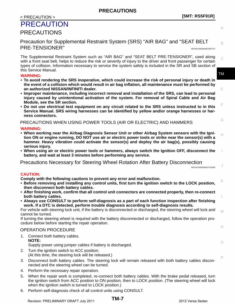
Precaution for Supplemental Restraint System (SRS) "AIR BAG" and "SEAT BELT PRE-TENSIONER" INFOID:0000000007697727
The Supplemental Restraint System such as “AIR BAG” and “SEAT BELT PRE-TENSIONER”, used alongwith a front seat belt, helps to reduce the risk or severity of injury to the driver and front passenger for certaintypes of collision. Information necessary to service the system safely is included in the SR and SB section ofthis Service Manual.WARNING:• To avoid rendering the SRS inoperative, which could increase the risk of personal injury or death in
the event of a collision which would result in air bag inflation, all maintenance must be performed byan authorized NISSAN/INFINITI dealer.
• Improper maintenance, including incorrect removal and installation of the SRS, can lead to personalinjury caused by unintentional activation of the system. For removal of Spiral Cable and Air BagModule, see the SR section.
• Do not use electrical test equipment on any circuit related to the SRS unless instructed to in thisService Manual. SRS wiring harnesses can be identified by yellow and/or orange harnesses or har-ness connectors.
PRECAUTIONS WHEN USING POWER TOOLS (AIR OR ELECTRIC) AND HAMMERSWARNING:• When working near the Airbag Diagnosis Sensor Unit or other Airbag System sensors with the Igni-
tion ON or engine running, DO NOT use air or electric power tools or strike near the sensor(s) with ahammer. Heavy vibration could activate the sensor(s) and deploy the air bag(s), possibly causingserious injury.
• When using air or electric power tools or hammers, always switch the Ignition OFF, disconnect thebattery, and wait at least 3 minutes before performing any service.
Precautions Necessary for Steering Wheel Rotation After Battery DisconnectionINFOID:0000000007225095
CAUTION:Comply with the following cautions to prevent any error and malfunction.• Before removing and installing any control units, first turn the ignition switch to the LOCK position,
then disconnect both battery cables.• After finishing work, confirm that all control unit connectors are connected properly, then re-connect
both battery cables.• Always use CONSULT to perform self-diagnosis as a part of each function inspection after finishing
work. If a DTC is detected, perform trouble diagnosis according to self-diagnosis results.For vehicle with steering lock unit, if the battery is disconnected or discharged, the steering wheel will lock andcannot be turned.If turning the steering wheel is required with the battery disconnected or discharged, follow the operation pro-cedure below before starting the repair operation.
OPERATION PROCEDURE1. Connect both battery cables.
NOTE:Supply power using jumper cables if battery is discharged.
2. Turn the ignition switch to ACC position.(At this time, the steering lock will be released.)
3. Disconnect both battery cables. The steering lock will remain released with both battery cables discon-nected and the steering wheel can be turned.
4. Perform the necessary repair operation.5. When the repair work is completed, re-connect both battery cables. With the brake pedal released, turn
the ignition switch from ACC position to ON position, then to LOCK position. (The steering wheel will lockwhen the ignition switch is turned to LOCK position.)
6. Perform self-diagnosis check of all control units using CONSULT.
TM-7Revision: PRELIMINARY DRAFT July 2011 2012 Versa Sedan

[5MT: RS5F91R]PRECAUTIONS
< PRECAUTION >
General Precautions INFOID:0000000007225096
CAUTION:• Do not reuse CSC (Concentric Slave Cylinder). CSC slides back to the original position every time
when removing transaxle assembly. At this time, dust on the sliding parts may damage the seal ofCSC and may cause clutch fluid leakage. Refer to CL-18, "Removal and Installation".
• Do not reuse transaxle gear oil, once it has been drained.• Check oil level or replace gear oil with vehicle on level surface.• During removal or installation, keep inside of transaxle clear of dust or dirt.• Check for the correct installation alignment prior to removal or disassembly. If matching marks are
required, be certain they never interfere with the function of the parts they marked.• In principle, tighten bolts or nuts gradually in several steps working diagonally from inside to out-
side. If tightening sequence is specified, use it.• Do not damage sliding surfaces and mating surfaces.
Precaution for Work INFOID:0000000007697728
• When removing or disassembling each component, be careful not to damage or deform it. If a componentmay be subject to interference, be sure to protect it with a shop cloth.
• When removing (disengaging) components with a screwdriver or similar tool, be sure to wrap the componentwith a shop cloth or vinyl tape to protect it.
• Protect the removed parts with a shop cloth and prevent them from being dropped.• Replace a deformed or damaged clip.• If a part is specified as a non-reusable part, always replace it with new one.• Be sure to tighten bolts and nuts securely to the specified torque.• After installation is complete, be sure to check that each part works properly.• Follow the steps below to clean components.- Water soluble dirt: Dip a soft cloth into lukewarm water, and wring the water out of the cloth to wipe the dirty
area.Then rub with a soft and dry cloth.
- Oily dirt: Dip a soft cloth into lukewarm water with mild detergent (concentration: within 2 to 3%), and wipethe dirty area.Then dip a cloth into fresh water, and wring the water out of the cloth to wipe the detergent off. Then rub witha soft and dry cloth.
• Do not use organic solvent such as thinner, benzene, alcohol, or gasoline.• For genuine leather seats, use a genuine leather seat cleaner.
TM-8Revision: PRELIMINARY DRAFT July 2011 2012 Versa Sedan

PREPARATION[5MT: RS5F91R]
C
E
F
G
H
I
J
K
L
M
A
B
M
N
O
P
< PREPARATION >
T
PREPARATIONPREPARATION
Special Service Tools INFOID:0000000007225097
Tool numberTool name
Description
KV32500QAA(Renault SST: B.vi 1666)Drift set1. —
(Stamping number: B.vi 1666-A)Drifta: 54.3 mm (2.138 in) dia.b: 45 mm (1.77 in) dia.c: 26.6 mm (1.047 in) dia.
2. —(Stamping number: B.vi 1666-B)Driftd: 54 mm (2.13 in) dia.e: 48.6 mm (1.913 in) dia.f: 26.6 mm (1.047 in) dia.
Installing differential side oil seal
KV32300QAC(Renault SST: B.vi 22-01)Puller
Removing 5th main gear
KV32300QAD(Renault SST: B.vi 1000-01)Puller
Removing 5th main gear
ST35300000Drifta: 45 mm (1.77 in) dia.b: 59 mm (2.32 in) dia.
• Removing and installing input shaft rear bearing
• Removing and installing mainshaft rear bearing
KV111011S0Valve seat remover
Removing mainshaft front bearing
JPDIC0730ZZ
SCIA1781J
SCIA1782J
ZZA0969D
ZZA0872D
TM-9Revision: PRELIMINARY DRAFT July 2011 2012 Versa Sedan
[5MT: RS5F91R]PREPARATION
< PREPARATION >
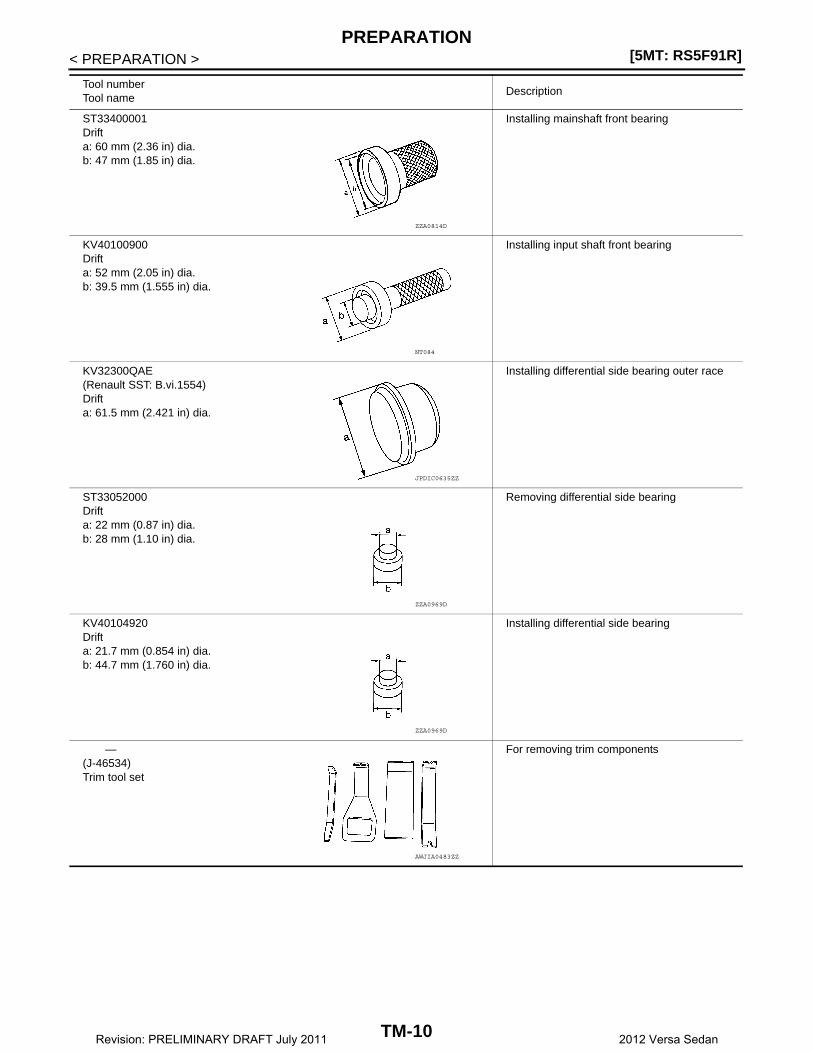
ST33400001Drifta: 60 mm (2.36 in) dia.b: 47 mm (1.85 in) dia.
Installing mainshaft front bearing
KV40100900Drifta: 52 mm (2.05 in) dia.b: 39.5 mm (1.555 in) dia.
Installing input shaft front bearing
KV32300QAE(Renault SST: B.vi.1554)Drifta: 61.5 mm (2.421 in) dia.
Installing differential side bearing outer race
ST33052000Drifta: 22 mm (0.87 in) dia.b: 28 mm (1.10 in) dia.
Removing differential side bearing
KV40104920Drifta: 21.7 mm (0.854 in) dia.b: 44.7 mm (1.760 in) dia.
Installing differential side bearing
—(J-46534)Trim tool set
For removing trim components
Tool numberTool name
Description
ZZA0814D
NT084
JPDIC0635ZZ
ZZA0969D
ZZA0969D
AWJIA0483ZZ
TM-10Revision: PRELIMINARY DRAFT July 2011 2012 Versa Sedan

PREPARATION[5MT: RS5F91R]
C
E
F
G
H
I
J
K
L
M
A
B
M
N
O
P
< PREPARATION >
T
Commercial Service Tools INFOID:0000000007225098
Tool name Description
Socketa: 8 mm (0.31 in)b: 5 mm (0.20 in)
Removing and installing drain plug
Drifta: 38 mm (1.50 in) dia.
Removing input shaft front bearing
Drifta: 14.5 mm (0.571 in) dia.
Installing bushing
Puller • Removing 5th-reverse synchronizer hub• Removing differential side bearing
Bearing remover Removing bushing
PCIB1776E
S-NT063
S-NT063
NT077
S-NT134
TM-11Revision: PRELIMINARY DRAFT July 2011 2012 Versa Sedan
[5MT: RS5F91R]COMPONENT PARTS
< SYSTEM DESCRIPTION >
SYSTEM DESCRIPTIONCOMPONENT PARTS
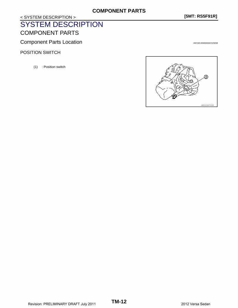
Component Parts Location INFOID:0000000007225099
POSITION SWITCH
(1) : Position switch
JPDIC0072ZZ
TM-12Revision: PRELIMINARY DRAFT July 2011 2012 Versa Sedan
STRUCTURE AND OPERATION[5MT: RS5F91R]
C
E
F
G
H
I
J
K
L
M
A
B
M
N
O
P
< SYSTEM DESCRIPTION >
T
STRUCTURE AND OPERATION
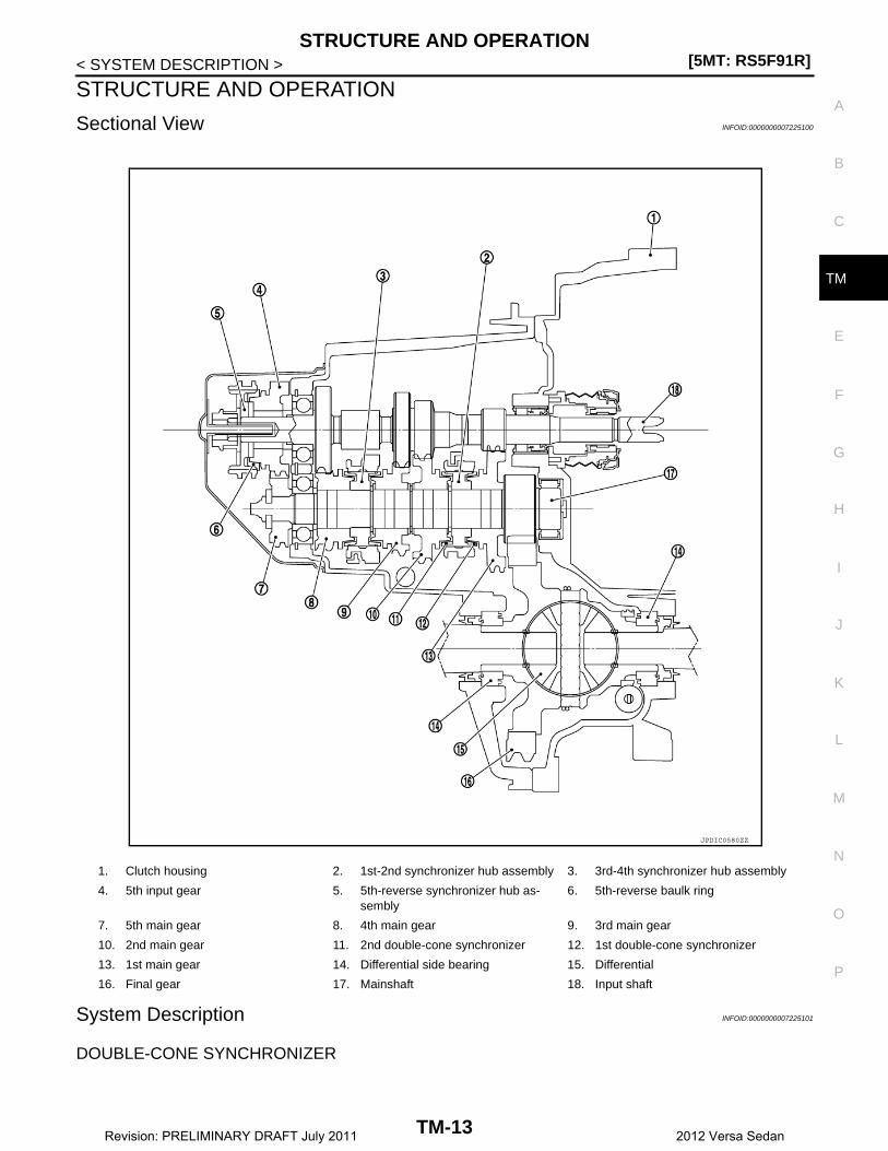
Sectional View INFOID:0000000007225100
System Description INFOID:0000000007225101
DOUBLE-CONE SYNCHRONIZER
1. Clutch housing 2. 1st-2nd synchronizer hub assembly 3. 3rd-4th synchronizer hub assembly
4. 5th input gear 5. 5th-reverse synchronizer hub as-sembly
6. 5th-reverse baulk ring
7. 5th main gear 8. 4th main gear 9. 3rd main gear
10. 2nd main gear 11. 2nd double-cone synchronizer 12. 1st double-cone synchronizer
13. 1st main gear 14. Differential side bearing 15. Differential
16. Final gear 17. Mainshaft 18. Input shaft
JPDIC0580ZZ
TM-13Revision: PRELIMINARY DRAFT July 2011 2012 Versa Sedan
[5MT: RS5F91R]STRUCTURE AND OPERATION
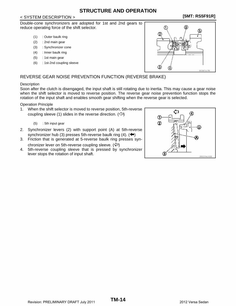
< SYSTEM DESCRIPTION >Double-cone synchronizers are adopted for 1st and 2nd gears toreduce operating force of the shift selector.
REVERSE GEAR NOISE PREVENTION FUNCTION (REVERSE BRAKE)
DescriptionSoon after the clutch is disengaged, the input shaft is still rotating due to inertia. This may cause a gear noisewhen the shift selector is moved to reverse position. The reverse gear noise prevention function stops therotation of the input shaft and enables smooth gear shifting when the reverse gear is selected.
Operation Principle1. When the shift selector is moved to reverse position, 5th-reverse
coupling sleeve (1) slides in the reverse direction. ( )
2. Synchronizer levers (2) with support point (A) at 5th-reversesynchronizer hub (3) presses 5th-reverse baulk ring (4). ( )
3. Friction that is generated at 5-reverse baulk ring presses syn-chronizer lever on 5th-reverse coupling sleeve. ( )
4. 5th-reverse coupling sleeve that is pressed by synchronizerlever stops the rotation of input shaft.
(1) : Outer baulk ring
(2) : 2nd main gear
(3) : Synchronizer cone
(4) : Inner baulk ring
(5) : 1st main gear
(6) : 1st-2nd coupling sleeve
SCIA7117E
(5) : 5th input gear
JPDIC0415ZZ
TM-14Revision: PRELIMINARY DRAFT July 2011 2012 Versa Sedan
POSITION SWITCH[5MT: RS5F91R]
C
E
F
G
H
I
J
K
L
M
A
B
M
N
O
P
< DTC/CIRCUIT DIAGNOSIS >
T
DTC/CIRCUIT DIAGNOSISPOSITION SWITCHBACK-UP LAMP SWITCH
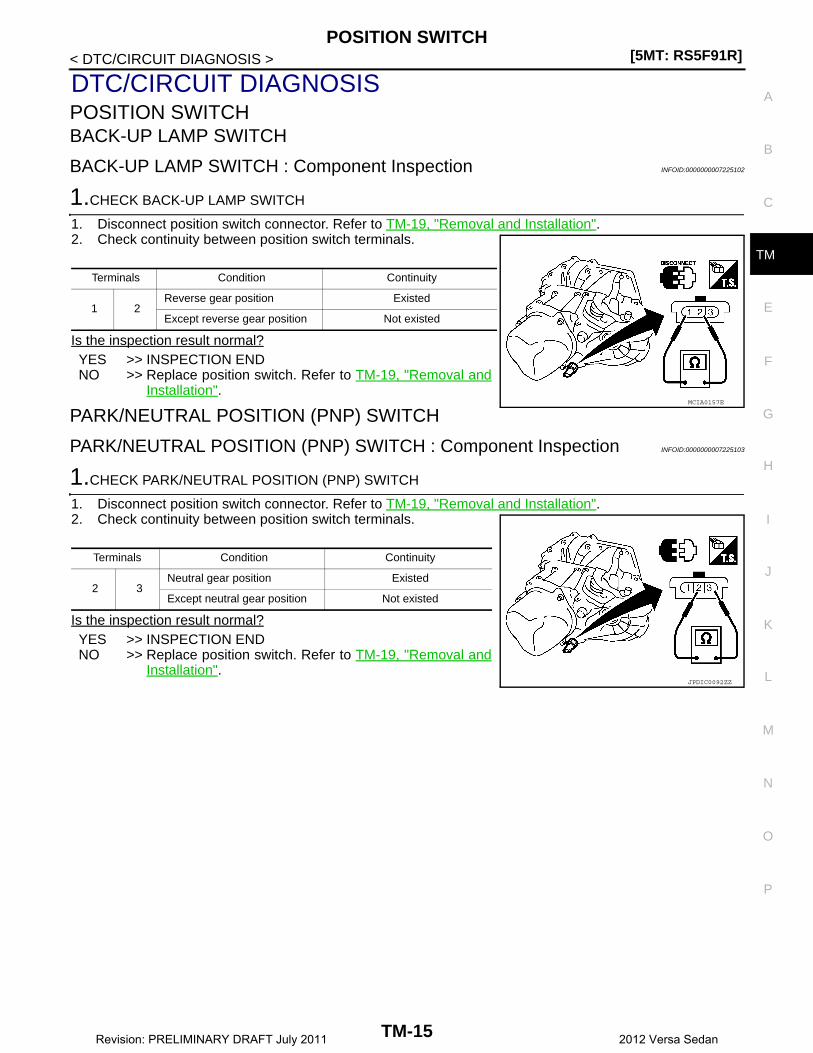
BACK-UP LAMP SWITCH : Component Inspection INFOID:0000000007225102
1.CHECK BACK-UP LAMP SWITCH
1. Disconnect position switch connector. Refer to TM-19, "Removal and Installation".2. Check continuity between position switch terminals.
Is the inspection result normal?YES >> INSPECTION ENDNO >> Replace position switch. Refer to TM-19, "Removal and
Installation".
PARK/NEUTRAL POSITION (PNP) SWITCH
PARK/NEUTRAL POSITION (PNP) SWITCH : Component Inspection INFOID:0000000007225103
1.CHECK PARK/NEUTRAL POSITION (PNP) SWITCH
1. Disconnect position switch connector. Refer to TM-19, "Removal and Installation".2. Check continuity between position switch terminals.
Is the inspection result normal?YES >> INSPECTION ENDNO >> Replace position switch. Refer to TM-19, "Removal and
Installation".
Terminals Condition Continuity
1 2Reverse gear position Existed
Except reverse gear position Not existed
MCIA0157E
Terminals Condition Continuity
2 3Neutral gear position Existed
Except neutral gear position Not existed
JPDIC0092ZZ
TM-15Revision: PRELIMINARY DRAFT July 2011 2012 Versa Sedan

[5MT: RS5F91R]NOISE, VIBRATION AND HARSHNESS (NVH) TROUBLESHOOTING
< SYMPTOM DIAGNOSIS >
SYMPTOM DIAGNOSISNOISE, VIBRATION AND HARSHNESS (NVH) TROUBLESHOOTING
NVH Troubleshooting Chart INFOID:0000000007225104
Use the chart below to find the cause of the symptom. The numbers indicate the order of the inspection. If nec-essary, repair or replace these parts.
Reference
TM
-17
TM
-27
TM
-21
TM
-27
SUSPECTED PARTS(Possible cause)
OIL
(O
il le
vel i
s lo
w)
OIL
(W
rong
oil)
OIL
(O
il le
vel i
s hi
gh)
GA
SK
ET
(D
amag
ed)
OIL
SE
AL
(Wor
n or
dam
aged
)
O-R
ING
(W
orn
or d
amag
ed)
SH
IFT
CO
NT
RO
L LI
NK
AG
E (
Wor
n)
SH
IFT
FO
RK
(W
orn)
GE
AR
(W
orn
or d
amag
ed)
BE
AR
ING
(W
orn
or d
amag
ed)
BA
ULK
RIN
G (
Wor
n or
dam
aged
)
INS
ER
T S
PR
ING
(D
amag
ed)
Symptoms
Noise 1 2 3 3
Oil leakage 3 1 2 2 2
Hard to shift or will not shift 1 1 2 3 3
Jumps out of gear 1 2 2
TM-16Revision: PRELIMINARY DRAFT July 2011 2012 Versa Sedan

GEAR OIL[5MT: RS5F91R]
C
E
F
G
H
I
J
K
L
M
A
B
M
N
O
P
< PERIODIC MAINTENANCE >
T
PERIODIC MAINTENANCEGEAR OIL
Inspection INFOID:0000000007225105
OIL LEAKAGEMake sure that gear oil is not leaking from transaxle or around it.
OIL LEVEL1. Remove filler plug (1) and gasket from transaxle case.2. Check the oil level from filler plug mounting hole as shown.
CAUTION:Do not start engine while checking oil level.
3. Install a gasket on filler plug and then install filler plug to tran-saxle case.CAUTION:Do not reuse gasket.
4. Tighten filler plug to the specified torque. Refer to TM-27,"Exploded View".
Draining INFOID:0000000007225106
1. Start engine and let it run to warm up transaxle.2. Stop engine. Remove drain plug (1) and gasket, using suitable
tool and then drain gear oil.3. Install a gasket on drain plug and install drain plug to clutch
housing, using suitable tool.CAUTION:Do not reuse gasket.
4. Tighten drain plug to the specified torque. Refer to TM-27,"Exploded View".
Refilling INFOID:0000000007225107
1. Remove filler plug (1) and gasket from transaxle case. 2. Fill with new gear oil until oil level reaches the specified limit at
filler plug mounting hole as shown.
3. After refilling gear oil, check the oil level. Refer to TM-17,"Inspection".
4. Install a gasket on filler plug and then install filler plug to transaxle case.CAUTION:Do not reuse gasket.
5. Tighten filler plug to the specified torque. Refer to TM-27, "Exploded View".
SCIA7119E
PCIB1504E
Oil grade and viscosity
: Refer to XX-XX, "*****".
Oil capacity : Refer to TM-55, "General Specifica-tions".
SCIA7119E
TM-17Revision: PRELIMINARY DRAFT July 2011 2012 Versa Sedan
[5MT: RS5F91R]SIDE OIL SEAL
< REMOVAL AND INSTALLATION >
REMOVAL AND INSTALLATIONSIDE OIL SEAL
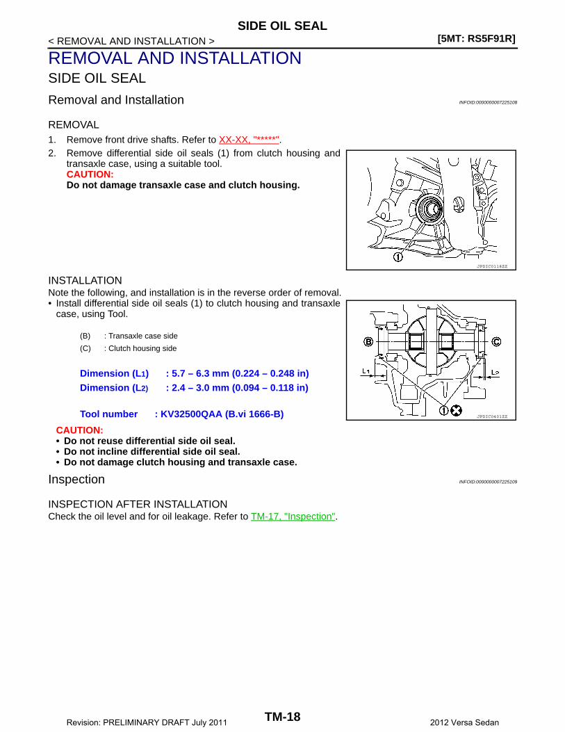
Removal and Installation INFOID:0000000007225108
REMOVAL1. Remove front drive shafts. Refer to XX-XX, "*****".2. Remove differential side oil seals (1) from clutch housing and
transaxle case, using a suitable tool.CAUTION:Do not damage transaxle case and clutch housing.
INSTALLATIONNote the following, and installation is in the reverse order of removal.• Install differential side oil seals (1) to clutch housing and transaxle
case, using Tool.
CAUTION:• Do not reuse differential side oil seal.• Do not incline differential side oil seal.• Do not damage clutch housing and transaxle case.
Inspection INFOID:0000000007225109
INSPECTION AFTER INSTALLATIONCheck the oil level and for oil leakage. Refer to TM-17, "Inspection".
JPDIC0118ZZ
(B) : Transaxle case side
(C) : Clutch housing side
Dimension (L1) : 5.7 – 6.3 mm (0.224 – 0.248 in)Dimension (L2) : 2.4 – 3.0 mm (0.094 – 0.118 in)
Tool number : KV32500QAA (B.vi 1666-B) JPDIC0401ZZ
TM-18Revision: PRELIMINARY DRAFT July 2011 2012 Versa Sedan

POSITION SWITCH[5MT: RS5F91R]
C
E
F
G
H
I
J
K
L
M
A
B
M
N
O
P
< REMOVAL AND INSTALLATION >
T
POSITION SWITCH
Removal and Installation INFOID:0000000007225110
REMOVAL1. Drain gear oil. Refer to TM-17, "Draining".2. Disconnect position switch connector (A).3. Remove position switch from transaxle case.
INSTALLATION1. Apply recommended sealant to threads of position switch.
• Use Genuine Silicone RTV or equivalent. Refer to Dummy cross-reference("XX-XX").CAUTION:Remove old sealant and oil adhering to threads.
2. Install position switch to transaxle case.3. Tighten position switch to the specified torque. Refer to TM-27, "Exploded View".4. Refill gear oil. Refer to TM-17, "Refilling".
Inspection INFOID:0000000007225111
INSPECTION AFTER INSTALLATION• Check continuity between position switch terminals. Refer to TM-15, "BACK-UP LAMP SWITCH : Compo-
nent Inspection" (Back-up lamp switch) and TM-15, "PARK/NEUTRAL POSITION (PNP) SWITCH : Compo-nent Inspection" (PNP switch).
• Check the oil level and for oil leakage. Refer to TM-17, "Inspection".
JPDIC0733ZZ
TM-19Revision: PRELIMINARY DRAFT July 2011 2012 Versa Sedan
[5MT: RS5F91R]CONTROL LINKAGE
< REMOVAL AND INSTALLATION >
CONTROL LINKAGE
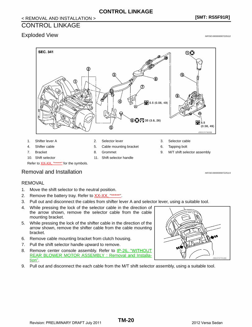
Exploded View INFOID:0000000007225112
Removal and Installation INFOID:0000000007225113
REMOVAL 1. Move the shift selector to the neutral position.2. Remove the battery tray. Refer to XX-XX, "*****".3. Pull out and disconnect the cables from shifter lever A and selector lever, using a suitable tool.4. While pressing the lock of the selector cable in the direction of
the arrow shown, remove the selector cable from the cablemounting bracket.
5. While pressing the lock of the shifter cable in the direction of thearrow shown, remove the shifter cable from the cable mountingbracket.
6. Remove cable mounting bracket from clutch housing.7. Pull the shift selector handle upward to remove.8. Remove center console assembly. Refer to IP-26, "WITHOUT
REAR BLOWER MOTOR ASSEMBLY : Removal and Installa-tion".
9. Pull out and disconnect the each cable from the M/T shift selector assembly, using a suitable tool.
1. Shifter lever A 2. Selector lever 3. Selector cable
4. Shifter cable 5. Cable mounting bracket 6. Tapping bolt
7. Bracket 8. Grommet 9. M/T shift selector assembly
10. Shift selector 11. Shift selector handle
Refer to XX-XX, "*****" for the symbols.
JPDIC0789GB
JPDIC0793ZZ
TM-20Revision: PRELIMINARY DRAFT July 2011 2012 Versa Sedan

CONTROL LINKAGE[5MT: RS5F91R]
C
E
F
G
H
I
J
K
L
M
A
B
M
N
O
P
< REMOVAL AND INSTALLATION >
T
a. While pressing the lock of the selector cable in the direction ofthe arrow shown, remove the selector cable from the M/T shiftselector assembly.
b. While pressing the lock of the shifter cable in the direction of thearrow shown, remove the shifter cable from the M/T shift selec-tor assembly.
10. Remove the M/T shift selector assembly.11. Remove center muffler, exhaust front tube, and heat plate. Refer
to XX-XX, "*****".12. Remove the bracket from the vehicle.13. Remove the grommet and then remove the shifter cable and
selector cable from the vehicle.
INSTALLATIONNote the following, and installation is in the reverse order of removal.CAUTION:• Install each cable without causing interference with other parts. Do not allow cable to bend less than
120 mm (4.72 in), or exceed 180 degree twist.• Install boot of each cable without causing interference with other parts. Do not exceed 90 degree
twist.• Fit boot to center console assembly and the groove on shift selector handle.• To install the shift selector handle, press it onto the shift selector.
CAUTION:• Do not reuse shift selector handle.• Be careful with orientation of shift selector handle.
• Bolt hole is not threaded on new clutch housing. Self-tapping bolt is used to attach lock plate to clutch hous-ing.CAUTION:Do not reuse self-tapping bolt.
• Insert each cable until it reaches the cable mounting bracket and M/T shift selector assembly.• Insert each cable until it reaches the shifter lever A and the selector lever.• Move the shift selector to the neutral position.
Inspection INFOID:0000000007225114
INSPECTION AFTER INSTALLATION
Shift Selector HandleCheck that the shift selector handle is installed in the right position.
Shifter Cable and Selector Cable• Pull each cable in the removal direction to check that it does not disconnect from the cable mounting
bracket.• Pull each cable in the removal direction to check that it does not disconnect from the M/T shift selector
assembly.• Pull grommet in the removal direction to check that it does not disconnect from the vehicle.
M/T Shift Selector Assembly and Shifter Selector• Check that there is no tangle, hook, abnormal sound, looseness, and interference when the shifter selector
is moved to each position. If there is a malfunction, then repair or replace the malfunctioning part. • Check that the shift selector smoothly returns to the neutral position after moving the shift selector from 1st
to 2nd gear and releasing it. If there is a malfunction, then repair or replace the malfunctioning part.• Check that the shift selector smoothly returns to the neutral position after moving the shift selector from 5th
to the reverse gear position and releasing it. If there is a malfunction, then repair or replace the malfunction-ing part.
JPDIC0793ZZ
TM-21Revision: PRELIMINARY DRAFT July 2011 2012 Versa Sedan
[5MT: RS5F91R]AIR BREATHER HOSE
< REMOVAL AND INSTALLATION >
AIR BREATHER HOSE
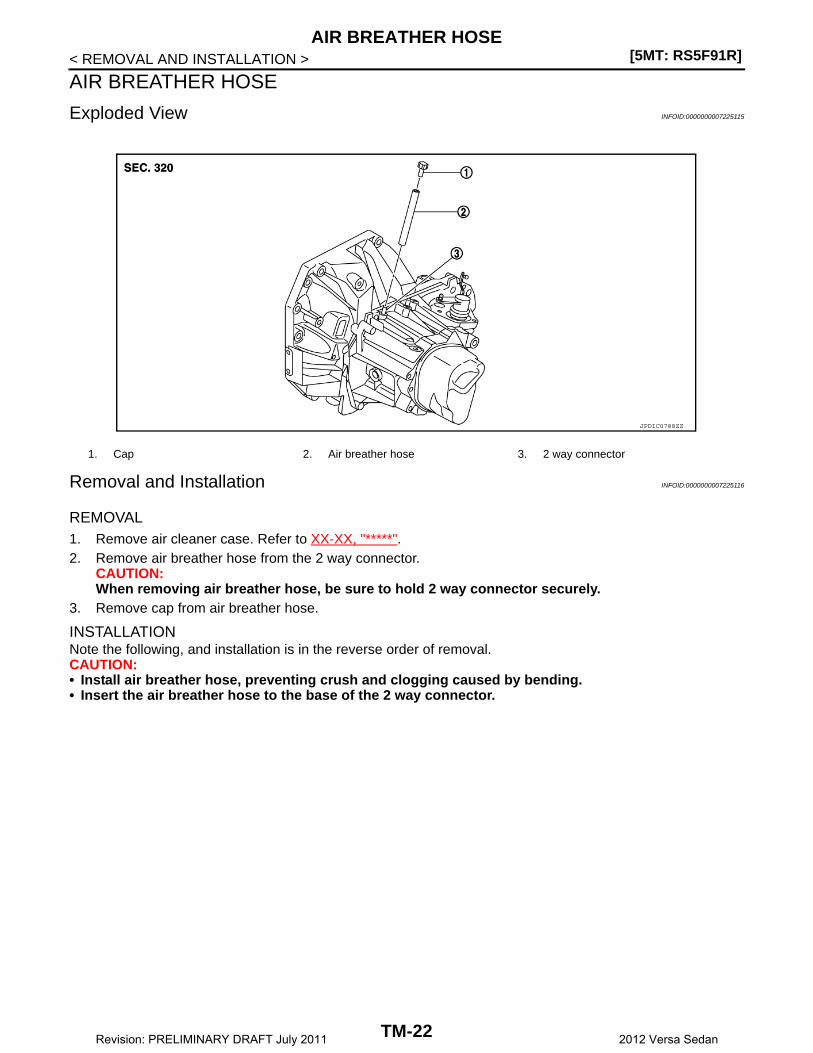
Exploded View INFOID:0000000007225115
Removal and Installation INFOID:0000000007225116
REMOVAL1. Remove air cleaner case. Refer to XX-XX, "*****".2. Remove air breather hose from the 2 way connector.
CAUTION:When removing air breather hose, be sure to hold 2 way connector securely.
3. Remove cap from air breather hose.
INSTALLATIONNote the following, and installation is in the reverse order of removal.CAUTION:• Install air breather hose, preventing crush and clogging caused by bending.• Insert the air breather hose to the base of the 2 way connector.
1. Cap 2. Air breather hose 3. 2 way connector
JPDIC0788ZZ
TM-22Revision: PRELIMINARY DRAFT July 2011 2012 Versa Sedan
5TH MAIN GEAR ASSEMBLY[5MT: RS5F91R]
C
E
F
G
H
I
J
K
L
M
A
B
M
N
O
P
< REMOVAL AND INSTALLATION >
T
5TH MAIN GEAR ASSEMBLY
Removal and Installation INFOID:0000000007225117
REMOVAL1. Move the shift selector to the 3rd gear position.2. Disconnect the shifter cable and the selector cable from shifter lever A and selector lever. Refer to TM-20,
"Removal and Installation".CAUTION:Do not move shifter lever A and the selector lever to disconnect each cable.
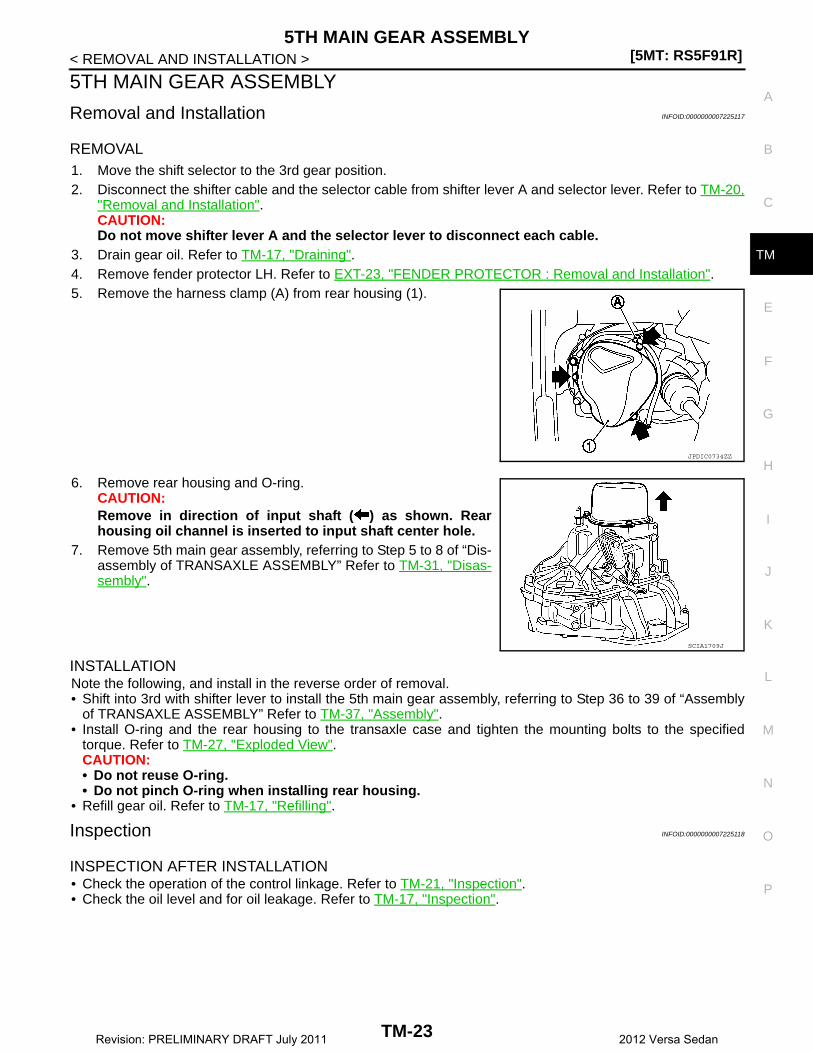
3. Drain gear oil. Refer to TM-17, "Draining".4. Remove fender protector LH. Refer to EXT-23, "FENDER PROTECTOR : Removal and Installation".5. Remove the harness clamp (A) from rear housing (1).
6. Remove rear housing and O-ring.CAUTION:Remove in direction of input shaft ( ) as shown. Rearhousing oil channel is inserted to input shaft center hole.
7. Remove 5th main gear assembly, referring to Step 5 to 8 of “Dis-assembly of TRANSAXLE ASSEMBLY” Refer to TM-31, "Disas-sembly".
INSTALLATIONNote the following, and install in the reverse order of removal.• Shift into 3rd with shifter lever to install the 5th main gear assembly, referring to Step 36 to 39 of “Assembly
of TRANSAXLE ASSEMBLY” Refer to TM-37, "Assembly".• Install O-ring and the rear housing to the transaxle case and tighten the mounting bolts to the specified
torque. Refer to TM-27, "Exploded View".CAUTION:• Do not reuse O-ring.• Do not pinch O-ring when installing rear housing.
• Refill gear oil. Refer to TM-17, "Refilling".
Inspection INFOID:0000000007225118
INSPECTION AFTER INSTALLATION• Check the operation of the control linkage. Refer to TM-21, "Inspection".• Check the oil level and for oil leakage. Refer to TM-17, "Inspection".
JPDIC0734ZZ
SCIA1709J
TM-23Revision: PRELIMINARY DRAFT July 2011 2012 Versa Sedan
[5MT: RS5F91R]TRANSAXLE ASSEMBLY
< UNIT REMOVAL AND INSTALLATION >
UNIT REMOVAL AND INSTALLATIONTRANSAXLE ASSEMBLY
Exploded View INFOID:0000000007225119
Removal and Installation INFOID:0000000007225120
CAUTION:Do not reuse CSC (Concentric Slave Cylinder). CSC slides back to the original position every timewhen removing transaxle assembly. At this time, dust on the sliding parts may damage the seal of CSCand may cause clutch fluid leakage. Refer to CL-18, "Removal and Installation".NOTE:When removing components such as hoses, tubes/lines, etc., cap or plug openings to prevent fluid from spill-ing.
REMOVAL1. Move the shift selector to the neutral position.2. Remove battery. Refer to XX-XX, "*****".3. Remove air cleaner case. Refer to XX-XX, "*****".4. Remove bolts (A) and nut (B).
5. Remove bracket (1).6. Remove air breather hose. Refer to TM-22, "Removal and
Installation".7. Disconnect selector cable and shifter cable from transaxle
assembly. Refer to TM-20, "Removal and Installation".8. Remove heat insulator. Refer to XX-XX, "*****".9. Remove crankshaft position sensor. Refer to XX-XX, "*****".10. Remove clutch tube clip from engine mounting bracket (LH).11. Remove clutch tube from CSC (Concentric Slave Cylinder) and then temporarily secure it to a position
where it will not inhibit work. Refer to CL-16, "Removal and Installation".CAUTION:
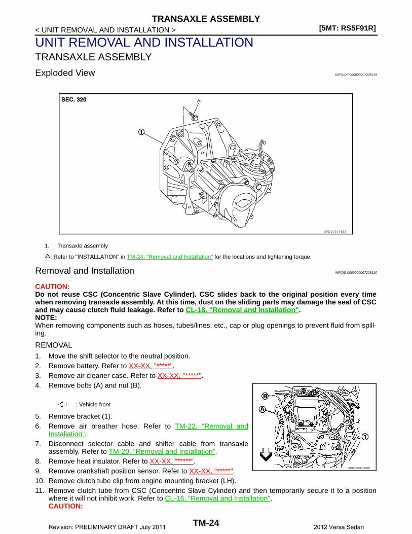
1. Transaxle assembly
: Refer to "INSTALLATION" in TM-24, "Removal and Installation" for the locations and tightening torque.
JPDIC0478ZZ
: Vehicle front
JPDIC0818ZZ
TM-24Revision: PRELIMINARY DRAFT July 2011 2012 Versa Sedan

TRANSAXLE ASSEMBLY[5MT: RS5F91R]
C
E
F
G
H
I
J
K
L
M
A
B
M
N
O
P
< UNIT REMOVAL AND INSTALLATION >
T
• Keep painted surface on the body or other parts free of clutch fluid. If it spills, wipe up immedi-ately and wash the affected area with water.
• Do not depress clutch pedal during removal procedure.12. Remove fender protector LH. Refer to EXT-23, "FENDER PROTECTOR : Removal and Installation".13. Disconnect ground cable.14. Disconnect position switch connector (A).15. Remove the harness clamp from rear housing.16. Remove the engine harness clamp and then temporarily secure
it to a position where it will not inhibit work.17. Remove starter motor. Refer to XX-XX, "*****".18. Remove front drive shafts. Refer to XX-XX, "*****".19. Set a suitable jack to transaxle assembly and then set a suitable
jack to engine assembly.CAUTION:When setting a suitable jack, be careful so that it does notcontact the position switch.
20. Remove engine mounting frame support (LH) bolts, per the following procedure.a. Remove bolt (A).
b. Release clutch damper (1) from bracket. Refer to CL-16,"Removal and Installation".
c. Remove bolt (B).d. Remove engine mounting bracket (LH) bolts from vehicle. Refer
to XX-XX, "*****".21. Remove rear engine mounting bracket and rear torque rod.
Refer to XX-XX, "*****".22. Remove transaxle assembly bolts and nuts.23. Remove transaxle assembly from the engine.
CAUTION:• Secure transaxle assembly to a suitable jack.• The transaxle assembly must not interfere with the wire harnesses and clutch tube.
24. Remove engine mounting bracket (LH) from transaxle assembly. Refer to EM-81, "Exploded View".25. Remove CSC. Refer to CL-18, "Removal and Installation".
INSTALLATIONNote the following, and installation is in the reverse order of removal.CAUTION:• Secure transaxle assembly to a suitable jack.• The transaxle assembly must not interfere with the wire harnesses and clutch tube.• When installing transaxle assembly, do not bring input shaft into contact with clutch cover.• Bolt hole is not threaded on new clutch housing. Self-tapping bolt is used to attach lock plate to
clutch housing.• Do not reuse self-tapping bolt.• Tighten transaxle assembly bolts to the specified torque. The illus-
tration is the view from the engine.
: Vehicle front
JPDIC0733ZZ
JPDIC0819ZZ
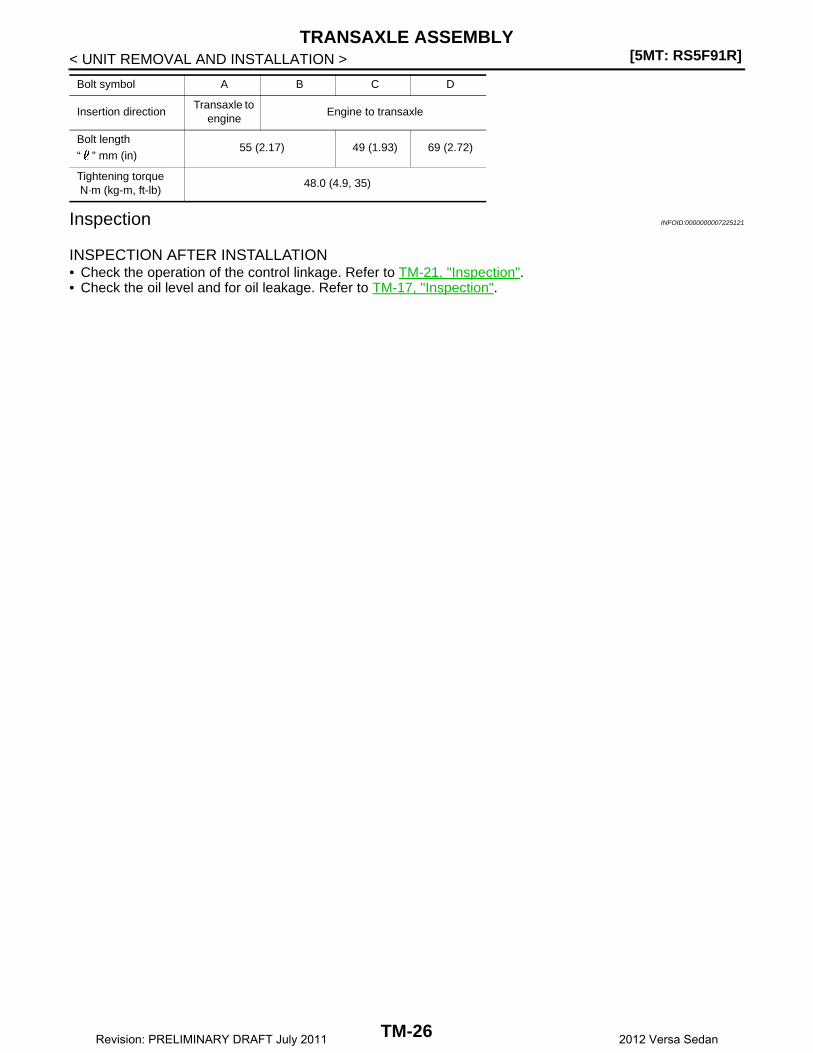
Bolt symbol A B C D
Insertion directionTransaxle to
engineEngine to transaxle
Quantity 2 3 2 1
JPDIC0813ZZ
TM-25Revision: PRELIMINARY DRAFT July 2011 2012 Versa Sedan
[5MT: RS5F91R]TRANSAXLE ASSEMBLY
< UNIT REMOVAL AND INSTALLATION >
Inspection INFOID:0000000007225121
INSPECTION AFTER INSTALLATION• Check the operation of the control linkage. Refer to TM-21, "Inspection".• Check the oil level and for oil leakage. Refer to TM-17, "Inspection".
Bolt length
“ ” mm (in)55 (2.17) 49 (1.93) 69 (2.72)
Tightening torque N·m (kg-m, ft-lb)
48.0 (4.9, 35)
Bolt symbol A B C D
Insertion directionTransaxle to
engineEngine to transaxle
TM-26Revision: PRELIMINARY DRAFT July 2011 2012 Versa Sedan
TRANSAXLE ASSEMBLY[5MT: RS5F91R]
C
E
F
G
H
I
J
K
L
M
A
B
M
N
O
P
< UNIT DISASSEMBLY AND ASSEMBLY >
T
UNIT DISASSEMBLY AND ASSEMBLYTRANSAXLE ASSEMBLY
Exploded View INFOID:0000000007225122
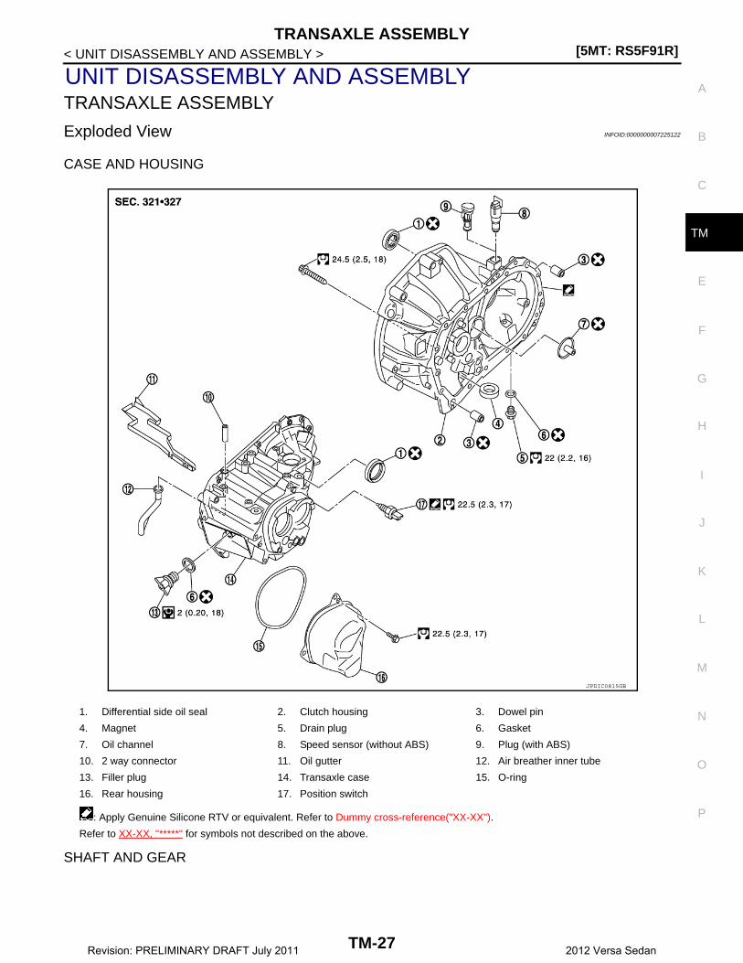
CASE AND HOUSING
SHAFT AND GEAR
1. Differential side oil seal 2. Clutch housing 3. Dowel pin
4. Magnet 5. Drain plug 6. Gasket
7. Oil channel 8. Speed sensor (without ABS) 9. Plug (with ABS)
10. 2 way connector 11. Oil gutter 12. Air breather inner tube
13. Filler plug 14. Transaxle case 15. O-ring
16. Rear housing 17. Position switch
: Apply Genuine Silicone RTV or equivalent. Refer to Dummy cross-reference("XX-XX").
Refer to XX-XX, "*****" for symbols not described on the above.
JPDIC0815GB
TM-27Revision: PRELIMINARY DRAFT July 2011 2012 Versa Sedan
[5MT: RS5F91R]TRANSAXLE ASSEMBLY
< UNIT DISASSEMBLY AND ASSEMBLY >
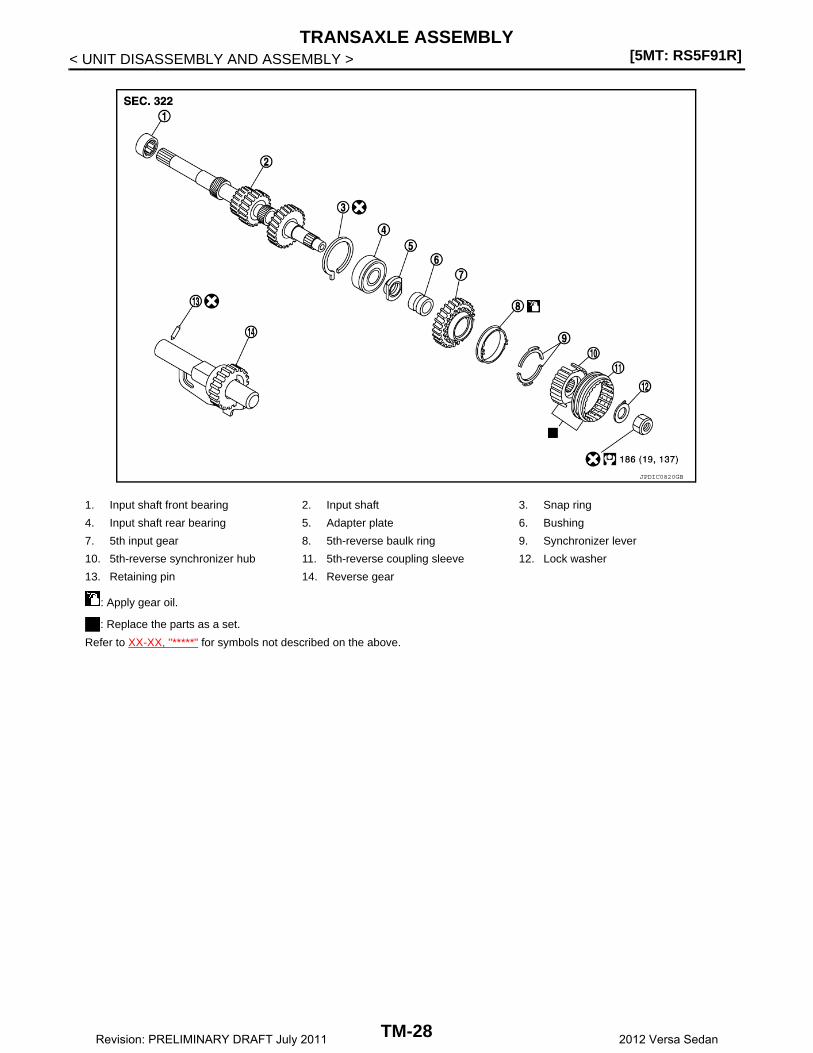
1. Input shaft front bearing 2. Input shaft 3. Snap ring
4. Input shaft rear bearing 5. Adapter plate 6. Bushing
7. 5th input gear 8. 5th-reverse baulk ring 9. Synchronizer lever
10. 5th-reverse synchronizer hub 11. 5th-reverse coupling sleeve 12. Lock washer
13. Retaining pin 14. Reverse gear
: Apply gear oil.
: Replace the parts as a set.
Refer to XX-XX, "*****" for symbols not described on the above.
JPDIC0820GB
TM-28Revision: PRELIMINARY DRAFT July 2011 2012 Versa Sedan

TRANSAXLE ASSEMBLY[5MT: RS5F91R]
C
E
F
G
H
I
J
K
L
M
A
B
M
N
O
P
< UNIT DISASSEMBLY AND ASSEMBLY >
T
SHIFT FORK AND FORK ROD
1. Mainshaft front bearing 2. Mainshaft 3. 1st main gear
4. 1st inner baulk ring 5. 1st synchronizer cone 6. 1st outer baulk ring
7. 1st-2nd synchronizer hub 8. 1st-2nd coupling sleeve 9. Spring
10. Insert key 11. 2nd outer baulk ring 12. 2nd synchronizer cone
13. 2nd inner baulk ring 14. Snap ring 15. Thrust washer
16. 2nd main gear 17. 3rd main gear 18. 3rd baulk ring
19. 3rd-4th synchronizer hub 20. 3rd-4th coupling sleeve 21. 4th baulk ring
22. 4th main gear 23. Spacer 24. Mainshaft rear bearing
25. 5th main gear
: Apply gear oil.
: Replace the parts as a set.
Refer to XX-XX, "*****" for symbols not described on the above.
JPDIC0531GB
TM-29Revision: PRELIMINARY DRAFT July 2011 2012 Versa Sedan
[5MT: RS5F91R]TRANSAXLE ASSEMBLY
< UNIT DISASSEMBLY AND ASSEMBLY >
FINAL DRIVE
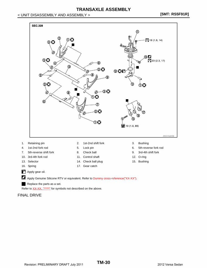
1. Retaining pin 2. 1st-2nd shift fork 3. Bushing
4. 1st-2nd fork rod 5. Lock pin 6. 5th-reverse fork rod
7. 5th-reverse shift fork 8. Check ball 9. 3rd-4th shift fork
10. 3rd-4th fork rod 11. Control shaft 12. O-ring
13. Selector 14. Check ball plug 15. Bushing
16. Spring 17. Gear catch
: Apply gear oil.
: Apply Genuine Silicone RTV or equivalent. Refer to Dummy cross-reference("XX-XX").
: Replace the parts as a set.
Refer to XX-XX, "*****" for symbols not described on the above.
JPDIC0485GB
TM-30Revision: PRELIMINARY DRAFT July 2011 2012 Versa Sedan
TRANSAXLE ASSEMBLY[5MT: RS5F91R]
C
E
F
G
H
I
J
K
L
M
A
B
M
N
O
P
< UNIT DISASSEMBLY AND ASSEMBLY >
T
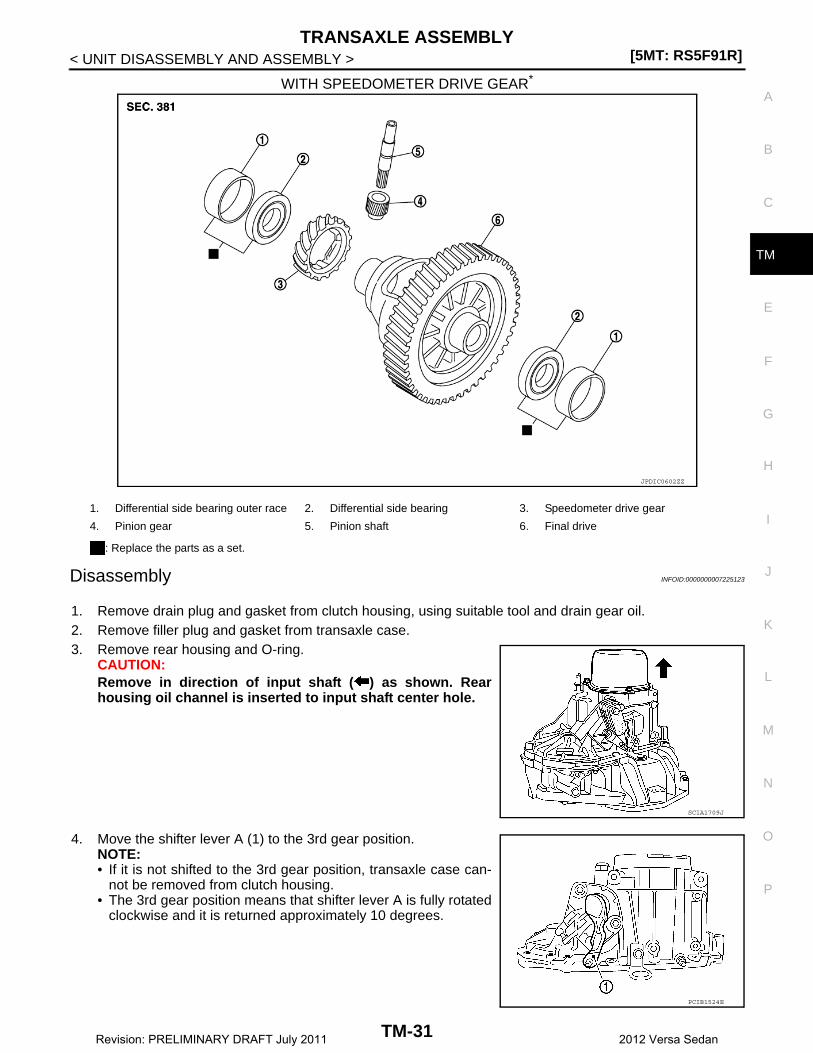
WITH SPEEDOMETER DRIVE GEAR*
Disassembly INFOID:0000000007225123
1. Remove drain plug and gasket from clutch housing, using suitable tool and drain gear oil.2. Remove filler plug and gasket from transaxle case.3. Remove rear housing and O-ring.
CAUTION:Remove in direction of input shaft ( ) as shown. Rearhousing oil channel is inserted to input shaft center hole.
4. Move the shifter lever A (1) to the 3rd gear position.NOTE:• If it is not shifted to the 3rd gear position, transaxle case can-
not be removed from clutch housing.• The 3rd gear position means that shifter lever A is fully rotated
clockwise and it is returned approximately 10 degrees.
JPDIC0602ZZ
1. Differential side bearing outer race 2. Differential side bearing 3. Speedometer drive gear
4. Pinion gear 5. Pinion shaft 6. Final drive
: Replace the parts as a set.
SCIA1709J
PCIB1524E
TM-31Revision: PRELIMINARY DRAFT July 2011 2012 Versa Sedan

[5MT: RS5F91R]TRANSAXLE ASSEMBLY
< UNIT DISASSEMBLY AND ASSEMBLY >
5. Remove 5th-reverse shift fork (1) and 5th-reverse couplingsleeve, per the following procedure.
a. Remove retaining pin from 5th-reverse shift fork, using suitabletool (A).
b. Press 5th-reverse shift fork, shift to 5th, and then engage it with3rd gear.
c. Remove bolt (B).d. Remove nut (C) and lock washer.
CAUTION:• Do not reuse nut.• Do not use an impact wrench for removal. Gears may be
damaged.e. Remove 5th-reverse shift fork and 5th-reverse coupling sleeve from 5th-reverse synchronizer hub.6. Remove 5th-reverse synchronizer hub from input shaft, using
suitable tool.CAUTION:Set claw of suitable tool to the wider side of the hub wheninstalling suitable tool in 5th-reverse synchronizer hub.
7. Remove synchronizer levers, 5th-reverse baulk ring, 5th inputgear, bushing, and adapter plate from input shaft.
8. Remove 5th main gear from mainshaft, using Tools.
9. Remove position switch from transaxle case.
JPDIC0532ZZ
PCIB1526E
Tool number (A): KV32300QAC (B.vi 22-01)(B): KV32300QAD (B.vi 1000-01)
PCIB1527E
PCIB1627E
TM-32Revision: PRELIMINARY DRAFT July 2011 2012 Versa Sedan
TRANSAXLE ASSEMBLY[5MT: RS5F91R]
C
E
F
G
H
I
J
K
L
M
A
B
M
N
O
P
< UNIT DISASSEMBLY AND ASSEMBLY >
T
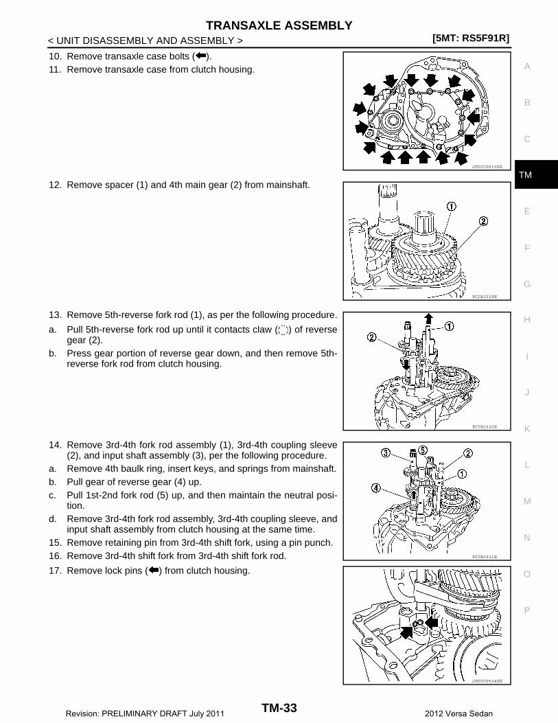
10. Remove transaxle case bolts ( ).11. Remove transaxle case from clutch housing.
12. Remove spacer (1) and 4th main gear (2) from mainshaft.
13. Remove 5th-reverse fork rod (1), as per the following procedure.
a. Pull 5th-reverse fork rod up until it contacts claw ( ) of reversegear (2).
b. Press gear portion of reverse gear down, and then remove 5th-reverse fork rod from clutch housing.
14. Remove 3rd-4th fork rod assembly (1), 3rd-4th coupling sleeve(2), and input shaft assembly (3), per the following procedure.
a. Remove 4th baulk ring, insert keys, and springs from mainshaft.b. Pull gear of reverse gear (4) up.c. Pull 1st-2nd fork rod (5) up, and then maintain the neutral posi-
tion.d. Remove 3rd-4th fork rod assembly, 3rd-4th coupling sleeve, and
input shaft assembly from clutch housing at the same time.15. Remove retaining pin from 3rd-4th shift fork, using a pin punch.16. Remove 3rd-4th shift fork from 3rd-4th shift fork rod.
17. Remove lock pins ( ) from clutch housing.
JPDIC0610ZZ
PCIB1529E
PCIB1530E
PCIB1531E
JPDIC0534ZZ
TM-33Revision: PRELIMINARY DRAFT July 2011 2012 Versa Sedan
[5MT: RS5F91R]TRANSAXLE ASSEMBLY
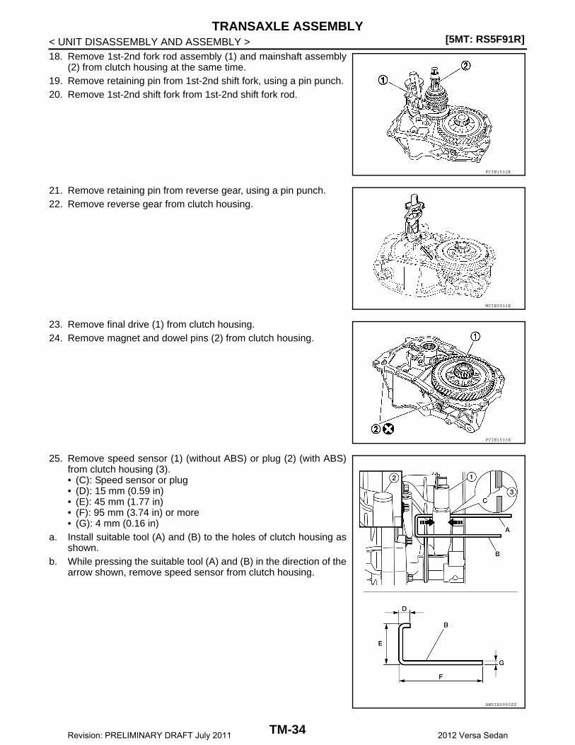
< UNIT DISASSEMBLY AND ASSEMBLY >18. Remove 1st-2nd fork rod assembly (1) and mainshaft assembly
(2) from clutch housing at the same time.19. Remove retaining pin from 1st-2nd shift fork, using a pin punch.20. Remove 1st-2nd shift fork from 1st-2nd shift fork rod.
21. Remove retaining pin from reverse gear, using a pin punch.22. Remove reverse gear from clutch housing.
23. Remove final drive (1) from clutch housing.24. Remove magnet and dowel pins (2) from clutch housing.
25. Remove speed sensor (1) (without ABS) or plug (2) (with ABS)from clutch housing (3).• (C): Speed sensor or plug• (D): 15 mm (0.59 in)• (E): 45 mm (1.77 in)• (F): 95 mm (3.74 in) or more• (G): 4 mm (0.16 in)
a. Install suitable tool (A) and (B) to the holes of clutch housing asshown.
b. While pressing the suitable tool (A) and (B) in the direction of thearrow shown, remove speed sensor from clutch housing.
PCIB1532E
MCIB0033E
PCIB1533E
AWDIA0950ZZ
TM-34Revision: PRELIMINARY DRAFT July 2011 2012 Versa Sedan

TRANSAXLE ASSEMBLY[5MT: RS5F91R]
C
E
F
G
H
I
J
K
L
M
A
B
M
N
O
P
< UNIT DISASSEMBLY AND ASSEMBLY >
T
26. Remove pinion gear and pinion shaft from clutch housing.27. Remove input shaft front bearing from clutch housing, using suit-
able tool.
28. Cut oil channel tube at the root.29. Remove mainshaft front bearing and oil channel from clutch
housing, using Tool (A).
30. Remove bushings (1) from clutch housing, using suitable tool.
31. Remove differential side oil seals (1) from clutch housing andtransaxle case, using a screwdriver.CAUTION:Never damage transaxle case and clutch housing.
MCIB0044E
Tool number : KV111011S0
PCIB1536E
PCIB1537E
PCIB1534E
TM-35Revision: PRELIMINARY DRAFT July 2011 2012 Versa Sedan

[5MT: RS5F91R]TRANSAXLE ASSEMBLY
< UNIT DISASSEMBLY AND ASSEMBLY >32. Remove differential side bearing outer races (1) from clutch
housing and transaxle case, using a brass rod.CAUTION:Never damage transaxle case and clutch housing.
33. Pull 2 way connector (1) straight to remove it from air breatherinner tube (2).
34. Remove air breather inner tube from transaxle case.
35. Remove bushings (1) from transaxle case, using suitable tool.
36. Remove retaining pin ( ) from selector, using suitable tool.37. Remove selector from control shaft.38. Remove oil gutter from transaxle case.
39. Remove bolt ( ), and then remove bushing, spring, and gearcatch from transaxle case.
40. Remove check ball plug from transaxle case.
41. Remove bolts ( ), and then remove control shaft (1) from tran-saxle case.
42. Remove O-ring from control shaft.
JPDIC0484ZZ
PCIB1541E
PCIB1538E
JPDIC0533ZZ
PCIB1540E
TM-36Revision: PRELIMINARY DRAFT July 2011 2012 Versa Sedan

TRANSAXLE ASSEMBLY[5MT: RS5F91R]
C
E
F
G
H
I
J
K
L
M
A
B
M
N
O
P
< UNIT DISASSEMBLY AND ASSEMBLY >
T
43. Expand snap rings (1) and remove input shaft rear bearing andmainshaft rear bearing from transaxle case, using the Tool (A).
44. Remove snap rings from transaxle case.45. Remove check balls (2) from transaxle case.
Assembly INFOID:0000000007225124
1. Install snap rings (1) along transaxle case groove so that notchmates with housing as shown.CAUTION:• Check snap ring installation direction.• Be sure to align notch with housing.
2. Expand snap rings (1) and install input shaft rear bearing andmainshaft rear bearing to transaxle case, using the Tool (A).CAUTION:Check that snap ring is correctly installed within bearinggroove.
3. Install check balls (2) to transaxle case.
4. Install bushings (1) until they reach transaxle case, using suit-able tool (A).
5. Apply gear oil to O-ring, and then install it to control shaft.CAUTION:Do not reuse O-ring.
Tool number : ST35300000
PCIB1535E
PCIB1547E
Tool number : ST35300000
PCIB1548E
JPDIC0636ZZ
TM-37Revision: PRELIMINARY DRAFT July 2011 2012 Versa Sedan

[5MT: RS5F91R]TRANSAXLE ASSEMBLY
< UNIT DISASSEMBLY AND ASSEMBLY >
6. Install control shaft (1) to transaxle case, and tighten bolts ( )to the specified torque.CAUTION:Replace control shaft and selector as a set.
7. Install selector to control shaft, and then install retaining pin ( )to selector, using suitable tool.CAUTION:• Be careful with the orientation of selector.• Replace control shaft and selector as a set.• Do not reuse retaining pin.
8. Install gear catch, spring, and bushing to transaxle case, andthen tighten bolt ( ) to the specified torque.CAUTION:Replace gear catch, spring, and bushing as a set.
9. Install oil gutter to transaxle case.
10. Install air breather inner tube (2) to transaxle case.CAUTION:Do not damage air breather inner tube.NOTE:It is easier to install when air breather inner tube end is wrappedand narrowed by tape. Remove tape after installation.
11. Insert 2 way connector (1) straight, and then install it to airbreather inner tube.CAUTION:Check air breather inner tube for twists after installing.
12. Install differential side oil seals (1) to clutch housing and tran-saxle case, using Tool.
PCIB1540E
SCIA1726J
JPDIC0533ZZ
PCIB1541E
(B) : Transaxle case side
(C) : Clutch housing side
Dimension (L1) : 5.7 – 6.3 mm (0.224 – 0.248 in)Dimension (L2) : 2.4 – 3.0 mm (0.094 – 0.118 in)
Tool number : KV32500QAA (B.vi 1666-B) JPDIC0401ZZ
TM-38Revision: PRELIMINARY DRAFT July 2011 2012 Versa Sedan

TRANSAXLE ASSEMBLY[5MT: RS5F91R]
C
E
F
G
H
I
J
K
L
M
A
B
M
N
O
P
< UNIT DISASSEMBLY AND ASSEMBLY >
T
CAUTION:• Do not incline differential side oil seal.• Do not damage clutch housing and transaxle case.
13. Install differential side bearing outer races until they reach clutchhousing and transaxle case, using Tool (A).CAUTION:Replace differential side bearing outer race and differentialside bearing as a set.
14. Install bushings (1) until they reach clutch housing, using suit-able tool (A).
15. Install oil channel to clutch housing.CAUTION:Do not reuse oil channel.
16. Install mainshaft front bearing so that it becomes even to clutchhousing surface, using Tool (A).
17. Install input shaft front bearing so that it becomes even to clutchhousing surface, using Tool (A).
18. Install pinion gear and pinion shaft to clutch housing.19. Install speed sensor (without ABS) or plug (with ABS).
Tool number : KV32300QAE (B.vi. 1554)
PCIB1549E
JPDIC0637ZZ
Tool number : ST33400001
PCIB1544E
Tool number : KV40100900
PCIB1545E
TM-39Revision: PRELIMINARY DRAFT July 2011 2012 Versa Sedan
[5MT: RS5F91R]TRANSAXLE ASSEMBLY
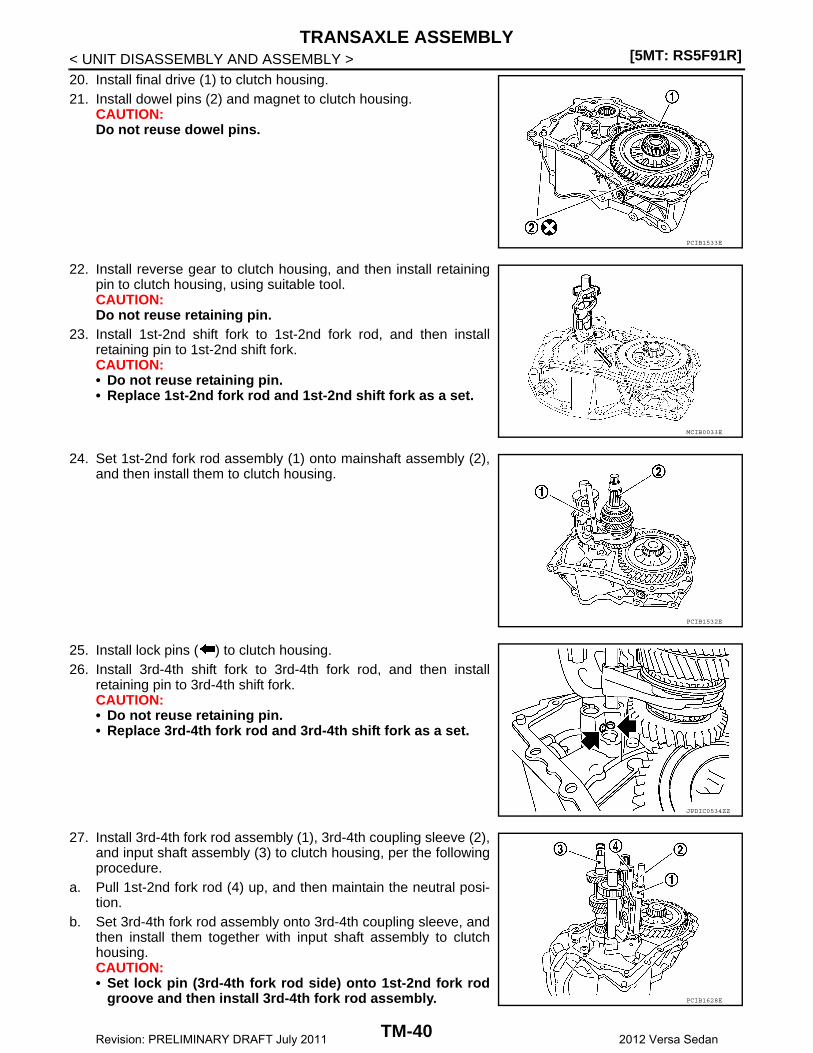
< UNIT DISASSEMBLY AND ASSEMBLY >20. Install final drive (1) to clutch housing.21. Install dowel pins (2) and magnet to clutch housing.
CAUTION:Do not reuse dowel pins.
22. Install reverse gear to clutch housing, and then install retainingpin to clutch housing, using suitable tool.CAUTION:Do not reuse retaining pin.
23. Install 1st-2nd shift fork to 1st-2nd fork rod, and then installretaining pin to 1st-2nd shift fork.CAUTION:• Do not reuse retaining pin.• Replace 1st-2nd fork rod and 1st-2nd shift fork as a set.
24. Set 1st-2nd fork rod assembly (1) onto mainshaft assembly (2),and then install them to clutch housing.
25. Install lock pins ( ) to clutch housing.26. Install 3rd-4th shift fork to 3rd-4th fork rod, and then install
retaining pin to 3rd-4th shift fork.CAUTION:• Do not reuse retaining pin.• Replace 3rd-4th fork rod and 3rd-4th shift fork as a set.
27. Install 3rd-4th fork rod assembly (1), 3rd-4th coupling sleeve (2),and input shaft assembly (3) to clutch housing, per the followingprocedure.
a. Pull 1st-2nd fork rod (4) up, and then maintain the neutral posi-tion.
b. Set 3rd-4th fork rod assembly onto 3rd-4th coupling sleeve, andthen install them together with input shaft assembly to clutchhousing.CAUTION:• Set lock pin (3rd-4th fork rod side) onto 1st-2nd fork rod
groove and then install 3rd-4th fork rod assembly.
PCIB1533E
MCIB0033E
PCIB1532E
JPDIC0534ZZ
PCIB1628E
TM-40Revision: PRELIMINARY DRAFT July 2011 2012 Versa Sedan
TRANSAXLE ASSEMBLY[5MT: RS5F91R]
C
E
F
G
H
I
J
K
L
M
A
B
M
N
O
P
< UNIT DISASSEMBLY AND ASSEMBLY >
T
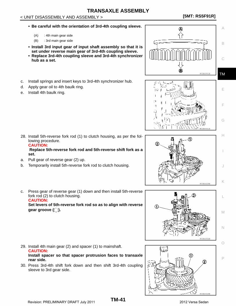
• Be careful with the orientation of 3rd-4th coupling sleeve.
• Install 3rd input gear of input shaft assembly so that it isset under reverse main gear of 3rd-4th coupling sleeve.
• Replace 3rd-4th coupling sleeve and 3rd-4th synchronizerhub as a set.
c. Install springs and insert keys to 3rd-4th synchronizer hub.d. Apply gear oil to 4th baulk ring.e. Install 4th baulk ring.
28. Install 5th-reverse fork rod (1) to clutch housing, as per the fol-lowing procedure.CAUTION: Replace 5th-reverse fork rod and 5th-reverse shift fork as aset.
a. Pull gear of reverse gear (2) up.b. Temporarily install 5th-reverse fork rod to clutch housing.
c. Press gear of reverse gear (1) down and then install 5th-reversefork rod (2) to clutch housing.CAUTION:Set levers of 5th-reverse fork rod so as to align with reversegear groove ( ).
29. Install 4th main gear (2) and spacer (1) to mainshaft.CAUTION:Install spacer so that spacer protrusion faces to transaxlerear side.
30. Press 3rd-4th shift fork down and then shift 3rd-4th couplingsleeve to 3rd gear side.
(A) : 4th main gear side
(B) : 3rd main gear side
PCIB1551E
MCIB0061E
PCIB1629E
PCIB1552E
PCIB1529E
TM-41Revision: PRELIMINARY DRAFT July 2011 2012 Versa Sedan

[5MT: RS5F91R]TRANSAXLE ASSEMBLY
< UNIT DISASSEMBLY AND ASSEMBLY >
31. Move the shifter lever A (1) to the 3rd gear position.NOTE:• If it is not moved to the 3rd gear position, transaxle case can-
not be installed to clutch housing.• The 3rd gear position means that shifter lever A is fully rotated
clockwise and it is returned approximately 10 degrees.32. Apply recommended sealant to transaxle case mounting surface
of clutch housing.• Use Genuine Silicone RTV or equivalent. Refer to Dummy
cross-reference("XX-XX").CAUTION:• Do not allow old silicone RTV, moisture, oil, or foreign
matter to remain on mounting surface.• Check that mounting surface is not damaged.• Apply a continuous bead of silicone RTV to the mounting surface.
33. Install transaxle case to clutch housing. If it is difficult to install,slightly rotate shifter lever A counterclockwise, and then install.
CAUTION:• Do not disrupt silicone RTV bead with transaxle case or
other objects during installation.• Be careful to align the lever of 5th-reverse fork rod with
reverse gear groove.
34. Rotate input shaft so that bearing and shaft fit each other, andthen tighten transaxle bolts ( ) to the specified torque.
35. Apply recommended sealant to position switch thread and checkball plug thread. Install to transaxle case and tighten to specifiedtorque.• Use Genuine Silicone RTV or equivalent. Refer to Dummy
cross-reference("XX-XX").CAUTION:Do not allow old silicone RTV, moisture, oil, or foreign mat-ter to remain on thread.
36. Apply gear oil to mainshaft spline.37. Install 5th main gear (1) to mainshaft, using a suitable bolt (A)
[M10 x 1.0] and a suitable nut (B).
PCIB1524E
(1) : Selector
(2) : Shift fork
PCIB1553E
JPDIC0610ZZ
PCIB1554E
TM-42Revision: PRELIMINARY DRAFT July 2011 2012 Versa Sedan

TRANSAXLE ASSEMBLY[5MT: RS5F91R]
C
E
F
G
H
I
J
K
L
M
A
B
M
N
O
P
< UNIT DISASSEMBLY AND ASSEMBLY >
T
38. Install adapter plate (1), bushing (2), and 5th input gear (3) toinput shaft.CAUTION:Be careful with the orientation of adapter plate.
39. Install 5th-reverse synchronizer hub, 5th-reverse coupling sleeve, and 5th-reverse shift fork, per the fol-lowing procedure.
a. Apply gear oil to 5th-reverse baulk ring.b. Install 5th-reverse baulk ring (1) to 5th input gear.
CAUTION:Be careful with the orientation of 5th-reverse baulk ring.
c. Install synchronizer levers (2) to 5th-reverse synchronizer hub(3).CAUTION:• Replace 5th-reverse synchronizer hub and 5th-reverse
coupling sleeve as a set.• Be careful with the orientation of synchronizer lever.
d. Install 5th-reverse synchronizer hub assembly and lock washer to input shaft.CAUTION:• Be careful with the orientation of 5th-reverse synchro-
nizer hub.
• Do not allow synchronizer lever (1) to mount on to 5th-reverse baulk ring (2) protrusion (A).
: Transaxle case side
PCIB1555E
: 5th-reverse synchronizer hub side
: 5th input gear side
JPDIC0421ZZ
PCIB1556E
(3) : 5th-reverse synchronizer hub
JPDIC0408ZZ
TM-43Revision: PRELIMINARY DRAFT July 2011 2012 Versa Sedan

[5MT: RS5F91R]TRANSAXLE ASSEMBLY
< UNIT DISASSEMBLY AND ASSEMBLY >e. Set 5th-reverse shift fork (1) to 5th-reverse coupling sleeve, and
then install them to 5th-reverse fork rod and input shaft.
CAUTION:• Be careful with the orientation of 5th-reverse coupling
sleeve.
• Replace 5th-reverse synchronizer hub and 5th-reversecoupling sleeve as a set.
• Replace 5th-reverse shift fork and 5th-reverse fork rod asa set.
f. Check that the gear position is in the 3rd position. Press 5th-reverse shift fork and shift to 5th gear.
g. Tighten bolt to the specified torque.h. Tighten nut to the specified torque.
CAUTION:Do not reuse nut.
i. Install retaining pin to 5th-reverse shift fork, using suitable tool.CAUTION:Do not reuse retaining pin.
40. Move the shifter lever A (1) to the neutral position.41. Install O-ring to rear housing.
CAUTION:Do not reuse O-ring.
42. Install rear housing to transaxle case, and tighten bolts ( ) tothe specified torque.CAUTION:• Do not reuse O-ring.• Do not pinch O-ring when installing rear housing.
43. Install drain plug, as per the following procedure.a. Install gasket to drain plug.
CAUTION:Do not reuse gasket.
b. Install drain plug to clutch housing, using a suitable tool.c. Tighten drain plug to the specified torque.44. Install filler plug, per the following procedure.a. Install gasket to filler plug, and then install filler plug to transaxle case.
CAUTION:Do not reuse gasket.
(A) : Pin punch
(B) : Mounting bolt
(C) : Mounting nut
JPDIC0532ZZ
: 5th input gear side
JPDIC0409ZZ
SCIA7130E
PCIB1558E
TM-44Revision: PRELIMINARY DRAFT July 2011 2012 Versa Sedan
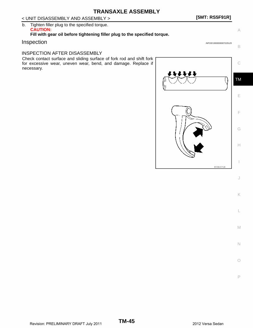
TRANSAXLE ASSEMBLY[5MT: RS5F91R]
C
E
F
G
H
I
J
K
L
M
A
B
M
N
O
P
< UNIT DISASSEMBLY AND ASSEMBLY >
T
b. Tighten filler plug to the specified torque.CAUTION:Fill with gear oil before tightening filler plug to the specified torque.
Inspection INFOID:0000000007225125
INSPECTION AFTER DISASSEMBLYCheck contact surface and sliding surface of fork rod and shift forkfor excessive wear, uneven wear, bend, and damage. Replace ifnecessary.
PCIB1571E
TM-45Revision: PRELIMINARY DRAFT July 2011 2012 Versa Sedan

[5MT: RS5F91R]INPUT SHAFT AND GEAR
< UNIT DISASSEMBLY AND ASSEMBLY >
INPUT SHAFT AND GEAR
Exploded View INFOID:0000000007225126
Disassembly INFOID:0000000007225127
Refer to TM-31, "Disassembly" for disassembly procedure.
Assembly INFOID:0000000007225128
Refer to TM-37, "Assembly" for assembly procedure.
Inspection INFOID:0000000007225129
INSPECTION AFTER DISASSEMBLY
Input Shaft and Gear
1. Input shaft front bearing 2. Input shaft 3. Snap ring
4. Input shaft rear bearing 5. Adapter plate 6. Bushing
7. 5th input gear 8. 5th-reverse baulk ring 9. Synchronizer lever
10. 5th-reverse synchronizer hub 11. 5th-reverse coupling sleeve 12. Lock washer
13. Retaining pin 14. Reverse gear
: Apply gear oil.
: Replace the parts as a set.
Refer to XX-XX, "*****" for symbols not described on the above.
JPDIC0820GB
TM-46Revision: PRELIMINARY DRAFT July 2011 2012 Versa Sedan
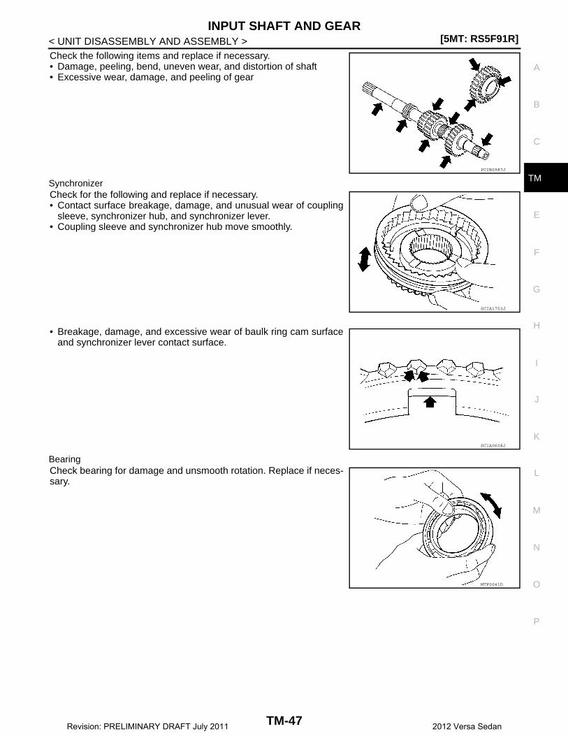
INPUT SHAFT AND GEAR[5MT: RS5F91R]
C
E
F
G
H
I
J
K
L
M
A
B
M
N
O
P
< UNIT DISASSEMBLY AND ASSEMBLY >
T
Check the following items and replace if necessary.• Damage, peeling, bend, uneven wear, and distortion of shaft• Excessive wear, damage, and peeling of gear
SynchronizerCheck for the following and replace if necessary.• Contact surface breakage, damage, and unusual wear of coupling
sleeve, synchronizer hub, and synchronizer lever.• Coupling sleeve and synchronizer hub move smoothly.
• Breakage, damage, and excessive wear of baulk ring cam surfaceand synchronizer lever contact surface.
BearingCheck bearing for damage and unsmooth rotation. Replace if neces-sary.
PCIB0987J
SCIA1753J
SCIA0608J
MTF0041D
TM-47Revision: PRELIMINARY DRAFT July 2011 2012 Versa Sedan
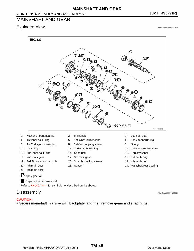
[5MT: RS5F91R]MAINSHAFT AND GEAR
< UNIT DISASSEMBLY AND ASSEMBLY >
MAINSHAFT AND GEAR
Exploded View INFOID:0000000007225130
Disassembly INFOID:0000000007225131
CAUTION:• Secure mainshaft in a vise with backplate, and then remove gears and snap rings.
1. Mainshaft front bearing 2. Mainshaft 3. 1st main gear
4. 1st inner baulk ring 5. 1st synchronizer cone 6. 1st outer baulk ring
7. 1st-2nd synchronizer hub 8. 1st-2nd coupling sleeve 9. Spring
10. Insert key 11. 2nd outer baulk ring 12. 2nd synchronizer cone
13. 2nd inner baulk ring 14. Snap ring 15. Thrust washer
16. 2nd main gear 17. 3rd main gear 18. 3rd baulk ring
19. 3rd-4th synchronizer hub 20. 3rd-4th coupling sleeve 21. 4th baulk ring
22. 4th main gear 23. Spacer 24. Mainshaft rear bearing
25. 5th main gear
: Apply gear oil.
: Replace the parts as a set.
Refer to XX-XX, "*****" for symbols not described on the above.
JPDIC0531GB
TM-48Revision: PRELIMINARY DRAFT July 2011 2012 Versa Sedan
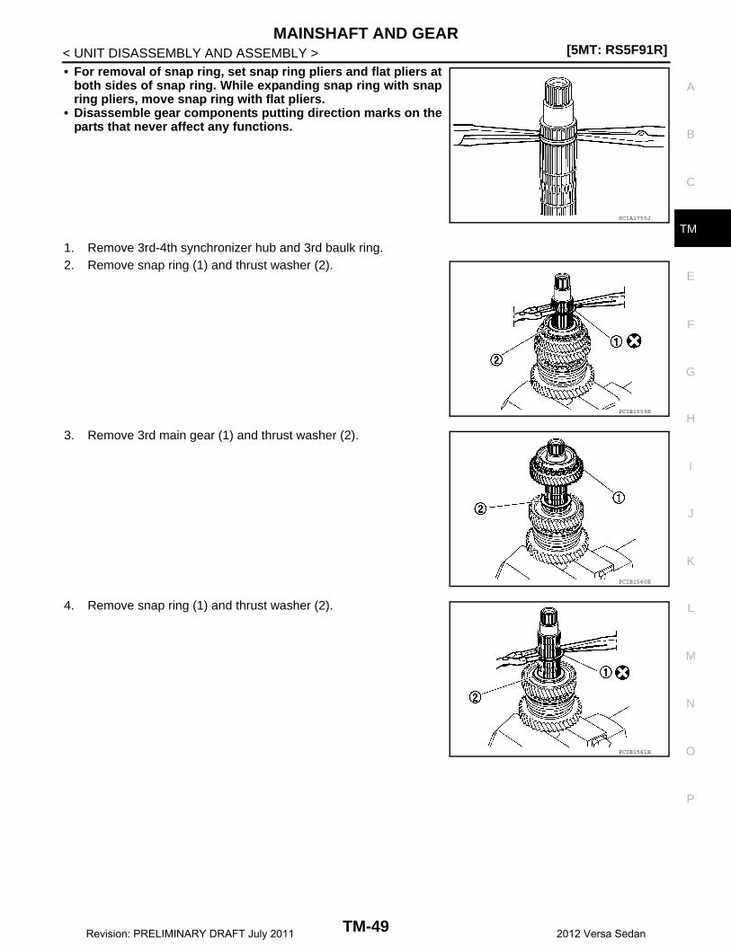
MAINSHAFT AND GEAR[5MT: RS5F91R]
C
E
F
G
H
I
J
K
L
M
A
B
M
N
O
P
< UNIT DISASSEMBLY AND ASSEMBLY >
T
• For removal of snap ring, set snap ring pliers and flat pliers atboth sides of snap ring. While expanding snap ring with snapring pliers, move snap ring with flat pliers.
• Disassemble gear components putting direction marks on theparts that never affect any functions.
1. Remove 3rd-4th synchronizer hub and 3rd baulk ring.2. Remove snap ring (1) and thrust washer (2).
3. Remove 3rd main gear (1) and thrust washer (2).
4. Remove snap ring (1) and thrust washer (2).
SCIA1755J
PCIB1559E
PCIB1560E
PCIB1561E
TM-49Revision: PRELIMINARY DRAFT July 2011 2012 Versa Sedan
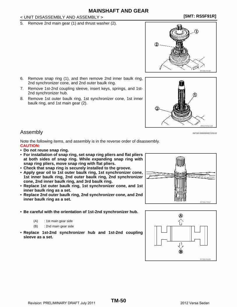
[5MT: RS5F91R]MAINSHAFT AND GEAR
< UNIT DISASSEMBLY AND ASSEMBLY >5. Remove 2nd main gear (1) and thrust washer (2).
6. Remove snap ring (1), and then remove 2nd inner baulk ring,2nd synchronizer cone, and 2nd outer baulk ring.
7. Remove 1st-2nd coupling sleeve, insert keys, springs, and 1st-2nd synchronizer hub.
8. Remove 1st outer baulk ring, 1st synchronizer cone, 1st innerbaulk ring, and 1st main gear (2).
Assembly INFOID:0000000007225132
Note the following items, and assembly is in the reverse order of disassembly.CAUTION:• Do not reuse snap ring.• For installation of snap ring, set snap ring pliers and flat pliers
at both sides of snap ring. While expanding snap ring withsnap ring pliers, move snap ring with flat pliers.
• Check that snap ring is securely installed to the groove.• Apply gear oil to 1st outer baulk ring, 1st synchronizer cone,
1st inner baulk ring, 2nd outer baulk ring, 2nd synchronizercone, 2nd inner baulk ring, and 3rd baulk ring.
• Replace 1st outer baulk ring, 1st synchronizer cone, and 1stinner baulk ring as a set.
• Replace 2nd outer baulk ring, 2nd synchronizer cone, and 2ndinner baulk ring as a set.
• Be careful with the orientation of 1st-2nd synchronizer hub.
• Replace 1st-2nd synchronizer hub and 1st-2nd couplingsleeve as a set.
PCIB1562E
JPDIC0541ZZ
SCIA1755J
(A) : 1st main gear side
(B) : 2nd main gear side
PCIB1566E
TM-50Revision: PRELIMINARY DRAFT July 2011 2012 Versa Sedan

MAINSHAFT AND GEAR[5MT: RS5F91R]
C
E
F
G
H
I
J
K
L
M
A
B
M
N
O
P
< UNIT DISASSEMBLY AND ASSEMBLY >
T
• Be careful with the orientation of 1st-2nd coupling sleeve.
• Be careful with the orientation of 3rd-4th synchronizer hub.
• Replace 3rd-4th synchronizer hub and 3rd-4th couplingsleeve as a set.
• Be careful with the orientation of insert key (1) and spring (2).
Inspection INFOID:0000000007225133
INSPECTION AFTER DISASSEMBLY
Mainshaft and GearCheck the following items and replace if necessary.• Damage, peeling, bend, uneven wear, and distortion of shaft• Excessive wear, damage, and peeling of gear
SynchronizerCheck the following items and replace if necessary.
(A) : 2nd main gear side
(B) : 1st main gear side
PCIB1567E
(A) : 4th main gear side
(B) : 3rd main gear side
PCIB1565E
PCIB1564E
SCIA1762J
TM-51Revision: PRELIMINARY DRAFT July 2011 2012 Versa Sedan

[5MT: RS5F91R]MAINSHAFT AND GEAR
< UNIT DISASSEMBLY AND ASSEMBLY >• Contact surface breakage, damage, and unusual wear of coupling
sleeve, synchronizer hub, insert key, and spring.• Coupling sleeve and synchronizer hub move smoothly.
• Breakage, damage, and excessive wear of baulk ring cam surfaceand insert contact surface
BearingCheck bearing for damage and unsmooth rotation. Replace if neces-sary.
SCIA1753J
SCIA0608J
MTF0041D
TM-52Revision: PRELIMINARY DRAFT July 2011 2012 Versa Sedan

FINAL DRIVE[5MT: RS5F91R]
C
E
F
G
H
I
J
K
L
M
A
B
M
N
O
P
< UNIT DISASSEMBLY AND ASSEMBLY >
T
FINAL DRIVE
Exploded View INFOID:0000000007225134
Disassembly INFOID:0000000007225135
1. Remove differential side bearings, using the Tool (A) and suit-able tool.
2. Remove speedometer drive gear.
1. Differential side bearing outer race 2. Differential side bearing 3. Speedometer drive gear
4. Pinion gear 5. Pinion shaft 6. Final drive
: Replace the parts as a set.
JPDIC0602ZZ
Tool number : ST33052000
PCIB1568E
TM-53Revision: PRELIMINARY DRAFT July 2011 2012 Versa Sedan
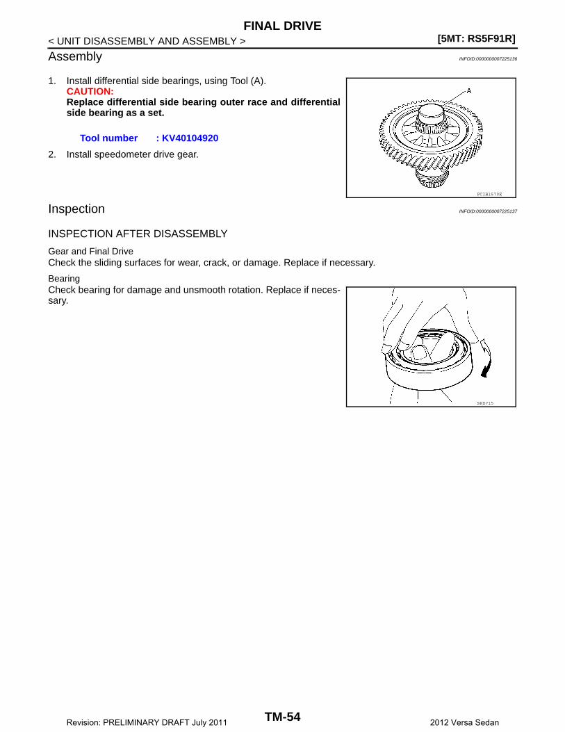
[5MT: RS5F91R]FINAL DRIVE
< UNIT DISASSEMBLY AND ASSEMBLY >
Assembly INFOID:0000000007225136
1. Install differential side bearings, using Tool (A).CAUTION:Replace differential side bearing outer race and differentialside bearing as a set.
2. Install speedometer drive gear.
Inspection INFOID:0000000007225137
INSPECTION AFTER DISASSEMBLY
Gear and Final DriveCheck the sliding surfaces for wear, crack, or damage. Replace if necessary.
BearingCheck bearing for damage and unsmooth rotation. Replace if neces-sary.
Tool number : KV40104920
PCIB1570E
SPD715
TM-54Revision: PRELIMINARY DRAFT July 2011 2012 Versa Sedan
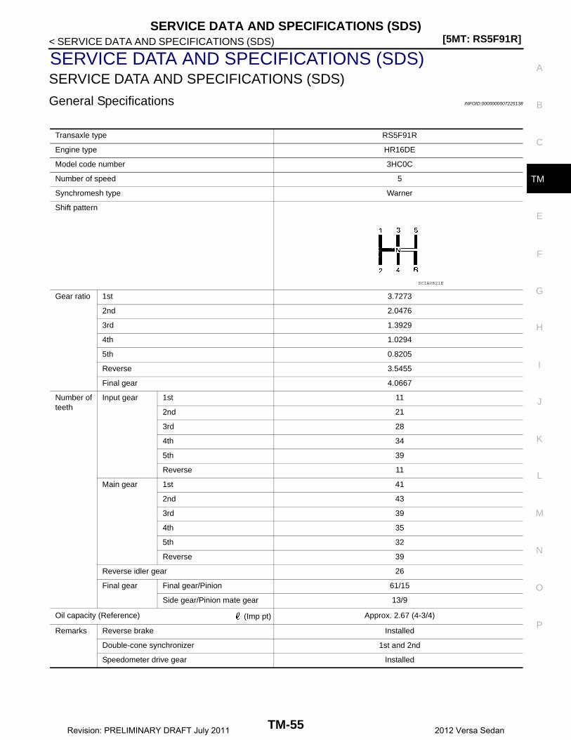
SERVICE DATA AND SPECIFICATIONS (SDS)[5MT: RS5F91R]
C
E
F
G
H
I
J
K
L
M
A
B
M
N
O
P
< SERVICE DATA AND SPECIFICATIONS (SDS)
T
SERVICE DATA AND SPECIFICATIONS (SDS)SERVICE DATA AND SPECIFICATIONS (SDS)
General Specifications INFOID:0000000007225138
Transaxle type RS5F91R
Engine type HR16DE
Model code number 3HC0C
Number of speed 5
Synchromesh type Warner
Shift pattern
Gear ratio 1st 3.7273
2nd 2.0476
3rd 1.3929
4th 1.0294
5th 0.8205
Reverse 3.5455
Final gear 4.0667
Number of teeth
Input gear 1st 11
2nd 21
3rd 28
4th 34
5th 39
Reverse 11
Main gear 1st 41
2nd 43
3rd 39
4th 35
5th 32
Reverse 39
Reverse idler gear 26
Final gear Final gear/Pinion 61/15
Side gear/Pinion mate gear 13/9
Oil capacity (Reference) (Imp pt) Approx. 2.67 (4-3/4)
Remarks Reverse brake Installed
Double-cone synchronizer 1st and 2nd
Speedometer drive gear Installed
SCIA0821E
TM-55Revision: PRELIMINARY DRAFT July 2011 2012 Versa Sedan

[4AT: RE4F03C]PRECAUTIONS
< PRECAUTION >
PRECAUTIONPRECAUTIONS
Precaution for Supplemental Restraint System (SRS) "AIR BAG" and "SEAT BELT PRE-TENSIONER" INFOID:0000000007240768
The Supplemental Restraint System such as “AIR BAG” and “SEAT BELT PRE-TENSIONER”, used alongwith a front seat belt, helps to reduce the risk or severity of injury to the driver and front passenger for certaintypes of collision. Information necessary to service the system safely is included in the “SRS AIR BAG” and“SEAT BELT” of this Service Manual.WARNING:Always observe the following items for preventing accidental activation.• To avoid rendering the SRS inoperative, which could increase the risk of personal injury or death in
the event of a collision that would result in air bag inflation, all maintenance must be performed byan authorized NISSAN/INFINITI dealer.
• Improper maintenance, including incorrect removal and installation of the SRS, can lead to personalinjury caused by unintentional activation of the system. For removal of Spiral Cable and Air BagModule, see “SRS AIR BAG”.
• Never use electrical test equipment on any circuit related to the SRS unless instructed to in this Ser-vice Manual. SRS wiring harnesses can be identified by yellow and/or orange harnesses or harnessconnectors.
PRECAUTIONS WHEN USING POWER TOOLS (AIR OR ELECTRIC) AND HAMMERSWARNING:Always observe the following items for preventing accidental activation.• When working near the Air Bag Diagnosis Sensor Unit or other Air Bag System sensors with the
ignition ON or engine running, never use air or electric power tools or strike near the sensor(s) witha hammer. Heavy vibration could activate the sensor(s) and deploy the air bag(s), possibly causingserious injury.
• When using air or electric power tools or hammers, always switch the ignition OFF, disconnect thebattery, and wait at least 3 minutes before performing any service.
Precautions Necessary for Steering Wheel Rotation After Battery DisconnectionINFOID:0000000007240769
CAUTION:Comply with the following cautions to prevent any error and malfunction.• Before removing and installing any control units, first turn the ignition switch to the LOCK position,
then disconnect both battery cables.• After finishing work, confirm that all control unit connectors are connected properly, then re-connect
both battery cables.• Always use CONSULT to perform self-diagnosis as a part of each function inspection after finishing
work. If a DTC is detected, perform trouble diagnosis according to self-diagnosis results.For vehicle with steering lock unit, if the battery is disconnected or discharged, the steering wheel will lock andcannot be turned.If turning the steering wheel is required with the battery disconnected or discharged, follow the operation pro-cedure below before starting the repair operation.
OPERATION PROCEDURE1. Connect both battery cables.
NOTE:Supply power using jumper cables if battery is discharged.
2. Turn the ignition switch to ACC position.(At this time, the steering lock will be released.)
3. Disconnect both battery cables. The steering lock will remain released with both battery cables discon-nected and the steering wheel can be turned.
4. Perform the necessary repair operation.
TM-56Revision: PRELIMINARY DRAFT July 2011 2012 Versa Sedan

PRECAUTIONS[4AT: RE4F03C]
C
E
F
G
H
I
J
K
L
M
A
B
M
N
O
P
< PRECAUTION >
T
5. When the repair work is completed, re-connect both battery cables. With the brake pedal released, turnthe ignition switch from ACC position to ON position, then to LOCK position. (The steering wheel will lockwhen the ignition switch is turned to LOCK position.)
6. Perform self-diagnosis check of all control units using CONSULT.
General Precautions INFOID:0000000007240770
• Turn the ignition switch OFF and disconnect the battery cablefrom the negative terminal before connecting or disconnect-ing the A/T assembly harness connector. Because batteryvoltage is applied to TCM even if ignition switch is turnedOFF.
• When connecting or disconnecting pin connectors into orfrom TCM, do not damage pin terminals (bend or break).Check that there are not any bends or breaks on TCM pin ter-minal, when connecting pin connectors.
• Perform TCM input/output signal inspection and checkwhether TCM functions normally or not before replacing TCM.Refer to TM-96, "Reference Value".
• Perform “DTC (Diagnostic Trouble Code) CONFIRMATIONPROCEDURE”.If the repair is completed DTC should not be displayed in the“DTC CONFIRMATION PROCEDURE”.
• Always use the specified brand of ATF. Refer to XX-XX, "*****".• Use lint-free paper not cloth rags during work.• Dispose of the waste oil using the methods prescribed by law, ordinance, etc. after replacing the ATF.
SEF289H
AAT470A
MEF040DA
JSBIA1315ZZ
TM-57Revision: PRELIMINARY DRAFT July 2011 2012 Versa Sedan
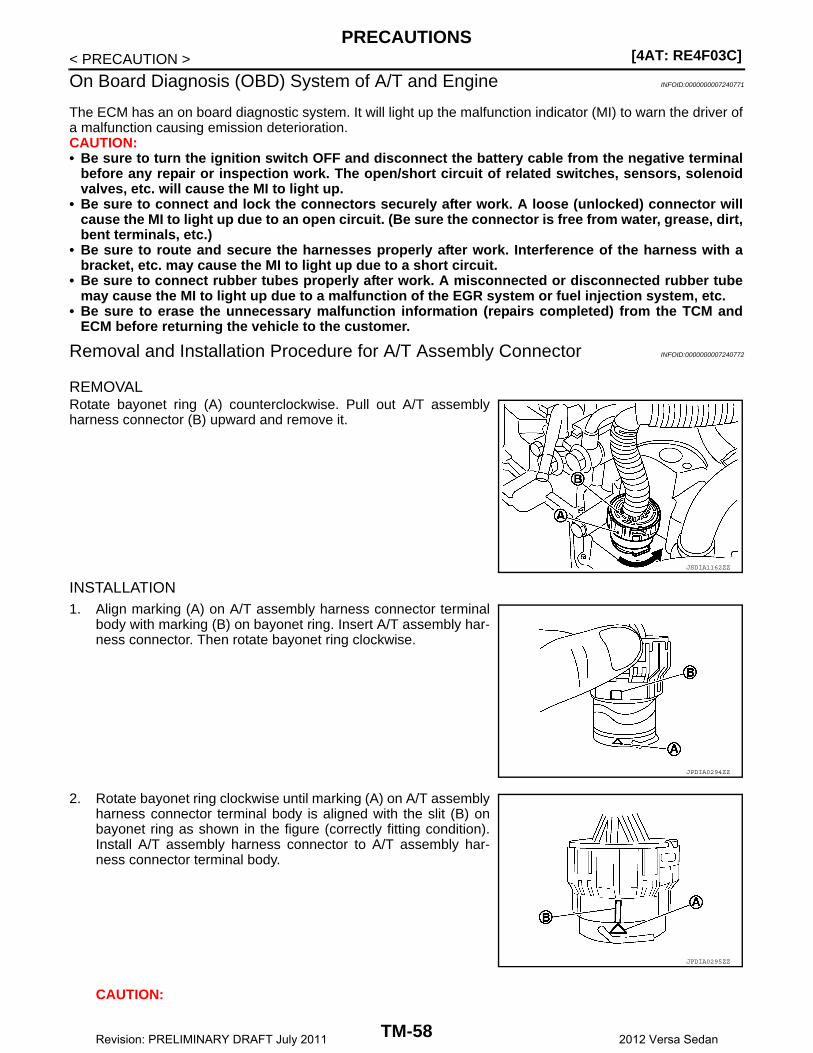
[4AT: RE4F03C]PRECAUTIONS
< PRECAUTION >
On Board Diagnosis (OBD) System of A/T and Engine INFOID:0000000007240771
The ECM has an on board diagnostic system. It will light up the malfunction indicator (MI) to warn the driver ofa malfunction causing emission deterioration.CAUTION:• Be sure to turn the ignition switch OFF and disconnect the battery cable from the negative terminal
before any repair or inspection work. The open/short circuit of related switches, sensors, solenoidvalves, etc. will cause the MI to light up.
• Be sure to connect and lock the connectors securely after work. A loose (unlocked) connector willcause the MI to light up due to an open circuit. (Be sure the connector is free from water, grease, dirt,bent terminals, etc.)
• Be sure to route and secure the harnesses properly after work. Interference of the harness with abracket, etc. may cause the MI to light up due to a short circuit.
• Be sure to connect rubber tubes properly after work. A misconnected or disconnected rubber tubemay cause the MI to light up due to a malfunction of the EGR system or fuel injection system, etc.
• Be sure to erase the unnecessary malfunction information (repairs completed) from the TCM andECM before returning the vehicle to the customer.
Removal and Installation Procedure for A/T Assembly Connector INFOID:0000000007240772
REMOVALRotate bayonet ring (A) counterclockwise. Pull out A/T assemblyharness connector (B) upward and remove it.
INSTALLATION1. Align marking (A) on A/T assembly harness connector terminal
body with marking (B) on bayonet ring. Insert A/T assembly har-ness connector. Then rotate bayonet ring clockwise.
2. Rotate bayonet ring clockwise until marking (A) on A/T assemblyharness connector terminal body is aligned with the slit (B) onbayonet ring as shown in the figure (correctly fitting condition).Install A/T assembly harness connector to A/T assembly har-ness connector terminal body.
CAUTION:
JSDIA1162ZZ
JPDIA0294ZZ
JPDIA0295ZZ
TM-58Revision: PRELIMINARY DRAFT July 2011 2012 Versa Sedan
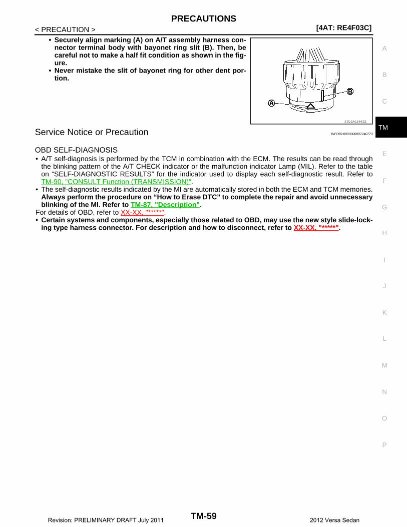
PRECAUTIONS[4AT: RE4F03C]
C
E
F
G
H
I
J
K
L
M
A
B
M
N
O
P
< PRECAUTION >
T
• Securely align marking (A) on A/T assembly harness con-nector terminal body with bayonet ring slit (B). Then, becareful not to make a half fit condition as shown in the fig-ure.
• Never mistake the slit of bayonet ring for other dent por-tion.
Service Notice or Precaution INFOID:0000000007240773
OBD SELF-DIAGNOSIS• A/T self-diagnosis is performed by the TCM in combination with the ECM. The results can be read through
the blinking pattern of the A/T CHECK indicator or the malfunction indicator Lamp (MIL). Refer to the tableon “SELF-DIAGNOSTIC RESULTS” for the indicator used to display each self-diagnostic result. Refer toTM-90, "CONSULT Function (TRANSMISSION)".
• The self-diagnostic results indicated by the MI are automatically stored in both the ECM and TCM memories.Always perform the procedure on “How to Erase DTC” to complete the repair and avoid unnecessaryblinking of the MI. Refer to TM-87, "Description".
For details of OBD, refer to XX-XX, "*****".• Certain systems and components, especially those related to OBD, may use the new style slide-lock-
ing type harness connector. For description and how to disconnect, refer to XX-XX, "*****".
JPDIA0296ZZ
TM-59Revision: PRELIMINARY DRAFT July 2011 2012 Versa Sedan
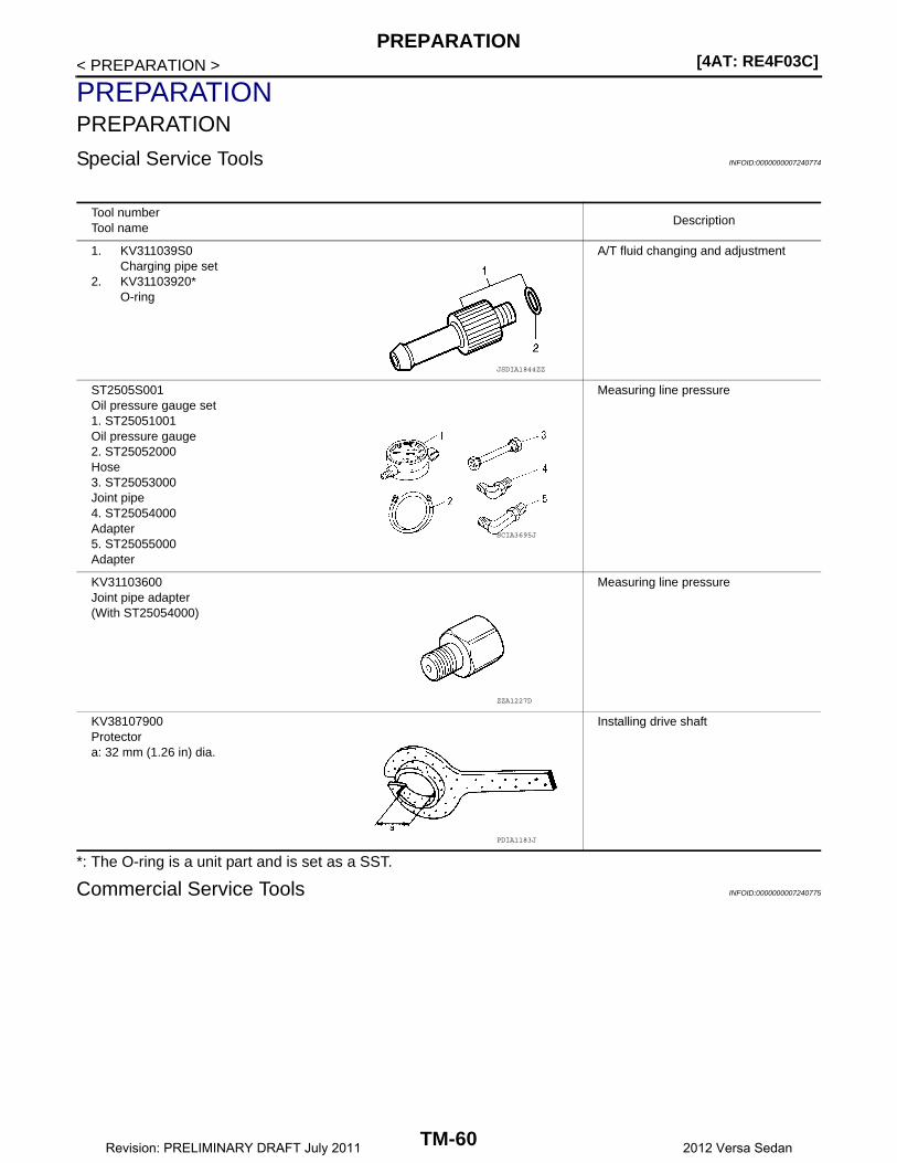
[4AT: RE4F03C]PREPARATION
< PREPARATION >
PREPARATIONPREPARATION
Special Service Tools INFOID:0000000007240774
*: The O-ring is a unit part and is set as a SST.
Commercial Service Tools INFOID:0000000007240775
Tool numberTool name
Description
1. KV311039S0Charging pipe set
2. KV31103920*O-ring
A/T fluid changing and adjustment
ST2505S001Oil pressure gauge set1. ST25051001Oil pressure gauge2. ST25052000Hose3. ST25053000Joint pipe4. ST25054000Adapter5. ST25055000Adapter
Measuring line pressure
KV31103600Joint pipe adapter(With ST25054000)
Measuring line pressure
KV38107900Protectora: 32 mm (1.26 in) dia.
Installing drive shaft
JSDIA1844ZZ
SCIA3695J
ZZA1227D
PDIA1183J
TM-60Revision: PRELIMINARY DRAFT July 2011 2012 Versa Sedan
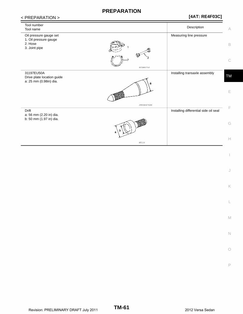
PREPARATION[4AT: RE4F03C]
C
E
F
G
H
I
J
K
L
M
A
B
M
N
O
P
< PREPARATION >
T
Tool numberTool name
Description
Oil pressure gauge set1. Oil pressure gauge2. Hose3. Joint pipe
Measuring line pressure
31197EU50ADrive plate location guidea: 25 mm (0.98in) dia.
Installing transaxle assembly
Drifta: 56 mm (2.20 in) dia.b: 50 mm (1.97 in) dia.
Installing differential side oil seal
SCIA8373J
JPDIA0676ZZ
NT115
TM-61Revision: PRELIMINARY DRAFT July 2011 2012 Versa Sedan

[4AT: RE4F03C]COMPONENT PARTS
< SYSTEM DESCRIPTION >
SYSTEM DESCRIPTIONCOMPONENT PARTSA/T CONTROL SYSTEM
A/T CONTROL SYSTEM : Component Parts Location INFOID:0000000007240776
A/T CONTROL SYSTEM : Component Description INFOID:0000000007240777
1. IPDM E/R 2. TCM 3. Transmission range switch
4. A/T unit 5. Output speed sensor 6. Stop lamp switch
7. A/T shift selector 8. Overdrive control switch 9. Combination meter (type A)
10. Combination meter (type B)
AWDIA0953ZZ
Name Function
TCM TM-63, "A/T CONTROL SYSTEM : TCM"
Transmission range switch TM-63, "A/T CONTROL SYSTEM : Transmission Range Switch"
Input speed sensor TM-63, "A/T CONTROL SYSTEM : Input Speed Sensor"
Output speed sensor TM-64, "A/T CONTROL SYSTEM : Output Speed Sensor"
A/T fluid temperature sensor TM-64, "A/T CONTROL SYSTEM : A/T Fluid Temperature Sensor"
Low clutch solenoid valve TM-65, "A/T CONTROL SYSTEM : Low Clutch Solenoid Valve"
2-4 brake solenoid valve TM-65, "A/T CONTROL SYSTEM : 2-4 Brake Solenoid Valve"
Select ON-OFF solenoid valve TM-65, "A/T CONTROL SYSTEM : Select Switch On-Off Solenoid Valve"
TM-62Revision: PRELIMINARY DRAFT July 2011 2012 Versa Sedan
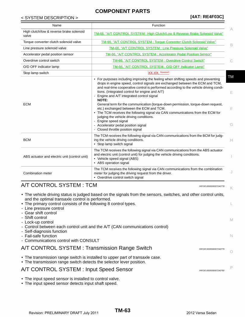
COMPONENT PARTS[4AT: RE4F03C]
C
E
F
G
H
I
J
K
L
M
A
B
M
N
O
P
< SYSTEM DESCRIPTION >
T
A/T CONTROL SYSTEM : TCM INFOID:0000000007240778
• The vehicle driving status is judged based on the signals from the sensors, switches, and other control units,and the optimal transaxle control is performed.
• The primary control consists of the following 8 control types.- Line pressure control- Gear shift control- Shift control- Lock-up control- Control between each control unit and the A/T (CAN communications control)- Self-diagnosis function- Fail-safe function- Communications control with CONSULT
A/T CONTROL SYSTEM : Transmission Range Switch INFOID:0000000007240779
• The transmission range switch is installed to upper part of transaxle case.• The transmission range switch detects the selector lever position.
A/T CONTROL SYSTEM : Input Speed Sensor INFOID:0000000007240780
• The input speed sensor is installed to control valve.• The input speed sensor detects input shaft speed.
High clutch/low & reverse brake solenoid valve
TM-66, "A/T CONTROL SYSTEM : High Clutch/Low & Reverse Brake Solenoid Valve"
Torque converter clutch solenoid valve TM-66, "A/T CONTROL SYSTEM : Torque Converter Clutch Solenoid Valve"
Line pressure solenoid valve TM-66, "A/T CONTROL SYSTEM : Line Pressure Solenoid Valve"
Accelerator pedal position sensor TM-66, "A/T CONTROL SYSTEM : Accelerator Pedal Position Sensor"
Overdrive control switch TM-66, "A/T CONTROL SYSTEM : Overdrive Control Switch"
O/D OFF indicator lamp TM-66, "A/T CONTROL SYSTEM : O/D OFF Indicator Lamp"
Stop lamp switch XX-XX, "*****"
ECM
• For purposes including improving the feeling when shifting speeds and preventing drops in engine speed, control signals are exchanged between the ECM and TCM, and real-time cooperative control is performed according to the vehicle driving condi-tions. (Integrated control for engine and A/T)
- Engine and A/T integrated control signalNOTE:General term for the communication (torque-down permission, torque-down request, etc.) exchanged between the ECM and TCM.
• The TCM receives the following signal via CAN communications from the ECM for judging the vehicle driving conditions.
- Engine speed signal- Accelerator pedal position signal- Closed throttle position signal
BCMThe TCM receives the following signal via CAN communications from the BCM for judg-ing the vehicle driving conditions.• Stop lamp switch signal
ABS actuator and electric unit (control unit)
The TCM receives the following signal via CAN communications from the ABS actuator and electric unit (control unit) for judging the vehicle driving conditions.• Vehicle speed signal (ABS)• ABS operation signal
Combination meterThe TCM receives the following signal via CAN communications from the combination meter for judging the driving request from the driver.• Overdrive control switch signal
Name Function
TM-63Revision: PRELIMINARY DRAFT July 2011 2012 Versa Sedan
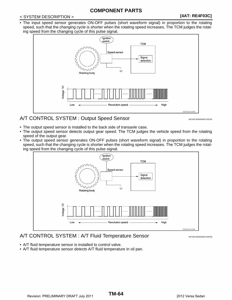
[4AT: RE4F03C]COMPONENT PARTS
< SYSTEM DESCRIPTION >• The input speed sensor generates ON-OFF pulses (short waveform signal) in proportion to the rotating
speed, such that the changing cycle is shorter when the rotating speed increases. The TCM judges the rotat-ing speed from the changing cycle of this pulse signal.
A/T CONTROL SYSTEM : Output Speed Sensor INFOID:0000000007240781
• The output speed sensor is installed to the back side of transaxle case.• The output speed sensor detects output gear speed. The TCM judges the vehicle speed from the rotating
speed of the output gear.• The output speed sensor generates ON-OFF pulses (short waveform signal) in proportion to the rotating
speed, such that the changing cycle is shorter when the rotating speed increases. The TCM judges the rotat-ing speed from the changing cycle of this pulse signal.
A/T CONTROL SYSTEM : A/T Fluid Temperature Sensor INFOID:0000000007240782
• A/T fluid temperature sensor is installed to control valve.• A/T fluid temperature sensor detects A/T fluid temperature in oil pan.
JSDIA1824GB
JSDIA1824GB
TM-64Revision: PRELIMINARY DRAFT July 2011 2012 Versa Sedan
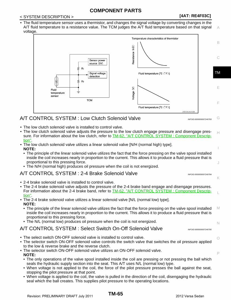
COMPONENT PARTS[4AT: RE4F03C]
C
E
F
G
H
I
J
K
L
M
A
B
M
N
O
P
< SYSTEM DESCRIPTION >
T
• The fluid temperature sensor uses a thermistor, and changes the signal voltage by converting changes in theA/T fluid temperature to a resistance value. The TCM judges the A/T fluid temperature based on that signalvoltage.
A/T CONTROL SYSTEM : Low Clutch Solenoid Valve INFOID:0000000007240783
• The low clutch solenoid valve is installed to control valve.• The low clutch solenoid valve adjusts the pressure to the low clutch engage pressure and disengage pres-
sure. For information about the low clutch, refer to TM-62, "A/T CONTROL SYSTEM : Component Descrip-tion".
• The low clutch solenoid valve utilizes a linear solenoid valve [N/H (normal high) type].NOTE:• The principle of the linear solenoid valve utilizes the fact that the force pressing on the valve spool installed
inside the coil increases nearly in proportion to the current. This allows it to produce a fluid pressure that isproportional to this pressing force.
• The N/H (normal high) produces oil pressure when the coil is not energized.
A/T CONTROL SYSTEM : 2-4 Brake Solenoid Valve INFOID:0000000007240784
• 2-4 brake solenoid valve is installed to control valve.• The 2-4 brake solenoid valve adjusts the pressure of the 2-4 brake band engage and disengage pressures.
For information about the 2-4 brake band, refer to TM-62, "A/T CONTROL SYSTEM : Component Descrip-tion".
• The 2-4 brake solenoid valve utilizes a linear solenoid valve [N/L (normal low) type].NOTE:• The principle of the linear solenoid valve utilizes the fact that the force pressing on the valve spool installed
inside the coil increases nearly in proportion to the current. This allows it to produce a fluid pressure that isproportional to this pressing force.
• The N/L (normal low) produces oil pressure when the coil is not energized.
A/T CONTROL SYSTEM : Select Switch On-Off Solenoid Valve INFOID:0000000007240785
• The select switch ON-OFF solenoid valve is installed to control valve.• The selector switch ON-OFF solenoid valve controls the switch valve that switches the oil pressure applied
to the low & reverse brake and the reverse clutch.• The selector switch ON-OFF solenoid valve utilizes an ON-OFF solenoid valve.
NOTE:• The only operations of the valve spool installed inside the coil are pressing or not pressing the ball which
seals the hydraulic supply section into the seat. This A/T uses N/L (normal low) type.• When voltage is not applied to the coil, the force of the pilot pressure presses the ball against the seat,
stopping the pilot pressure at that point.• When voltage is applied to the coil, the valve is pulled in the direction of the coil, disengaging the hydraulic
seal which the ball creates. This supplies pilot pressure to the operating locations.
JSDIA1825GB
TM-65Revision: PRELIMINARY DRAFT July 2011 2012 Versa Sedan

[4AT: RE4F03C]COMPONENT PARTS
< SYSTEM DESCRIPTION >
A/T CONTROL SYSTEM : High Clutch/Low & Reverse Brake Solenoid ValveINFOID:0000000007240786
• The high clutch/low & reverse brake solenoid valve is installed to control valve.• The high clutch/low & reverse brake solenoid valve adjusts the pressure to the high clutch and low & reverse
brake engage pressure and disengage pressure.• The high clutch/low & reverse brake solenoid valve utilizes a linear solenoid valve [N/H (normal high) type].
NOTE:• The principle of the linear solenoid valve utilizes the fact that the force pressing on the valve spool installed
inside the coil increases nearly in proportion to the current. This allows it to produce a fluid pressure that isproportional to this pressing force.
• The N/H (normal high) produces oil pressure when the coil is not energized.
A/T CONTROL SYSTEM : Torque Converter Clutch Solenoid Valve INFOID:0000000007240787
• The torque converter solenoid valve is installed to control valve.• The torque converter solenoid valve controls the lock-up control valve. For information about the lock-up
control valve, refer to TM-62, "A/T CONTROL SYSTEM : Component Description".• The high clutch solenoid valve utilizes a linear solenoid valve [N/H (normal low) type].
NOTE:• The principle of the linear solenoid valve utilizes the fact that the force pressing on the valve spool installed
inside the coil increases nearly in proportion to the current. This allows it to produce a fluid pressure that isproportional to this pressing force.
• The N/L (normal low) type does not produce oil pressure when the coil is not energized.
A/T CONTROL SYSTEM : Line Pressure Solenoid Valve INFOID:0000000007240788
• The line pressure solenoid valve is installed to control valve.• The line pressure solenoid valve controls the line pressure control valve. For information about the line pres-
sure control valve, refer to TM-62, "A/T CONTROL SYSTEM : Component Description".• The line pressure solenoid valve utilizes a linear solenoid valve [N/H (normal high) type].
NOTE:• The principle of the linear solenoid valve utilizes the fact that the force pressing on the valve spool installed
inside the coil increases nearly in proportion to the current. This allows it to produce a fluid pressure that isproportional to this pressing force.
• The N/H (normal high) produces oil pressure when the coil is not energized.
A/T CONTROL SYSTEM : Accelerator Pedal Position Sensor INFOID:0000000007240789
• The accelerator pedal position sensor is installed above the accelerator pedal.• The accelerator pedal position sensor detects the amount that the accelerator pedal is depressed.• The accelerator pedal position sensor converts the amount of accelerator pedal depression into a voltage
signal. The ECM judges the throttle position based on this voltage signal, and sends it via CAN communica-tion to the TCM.
A/T CONTROL SYSTEM : Overdrive Control Switch INFOID:0000000007240790
• The overdrive control switch is installed on the selector lever knob.• If the overdrive control switch is pressed when the O/D OFF indicator lamp on the combination meter is not
lit, the status changes to overdrive OFF and the O/D OFF indicator lamp illuminates.• If the overdrive control switch is pressed when the O/D OFF indicator lamp on the combination meter is lit,
the overdrive OFF status is canceled and the O/D OFF indicator lamp turns off.
A/T CONTROL SYSTEM : O/D OFF Indicator Lamp INFOID:0000000007240791
• The O/D OFF indicator lamp is positioned on the combination meter.• The O/D OFF indicator lamp illuminates when the overdrive function is deactivated (O/D OFF).• For checking the bulb, this lamp turns on for a certain period of time when the ignition switch turns ON, and
then turns off.
TM-66Revision: PRELIMINARY DRAFT July 2011 2012 Versa Sedan
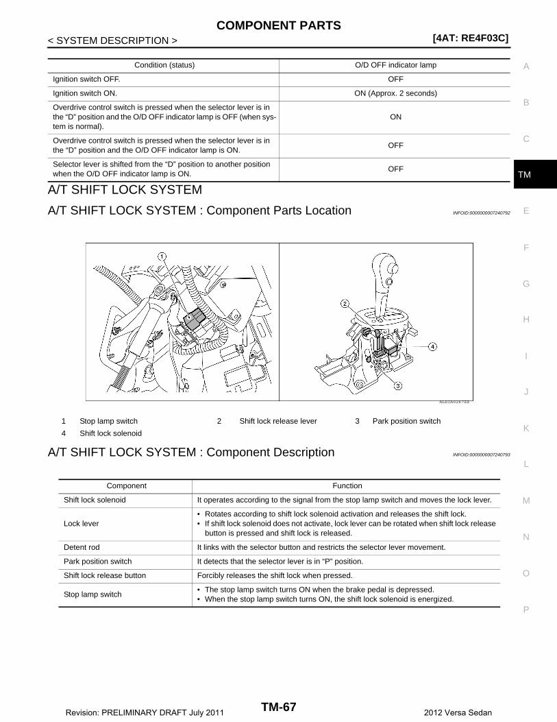
COMPONENT PARTS[4AT: RE4F03C]
C
E
F
G
H
I
J
K
L
M
A
B
M
N
O
P
< SYSTEM DESCRIPTION >
T
A/T SHIFT LOCK SYSTEM
A/T SHIFT LOCK SYSTEM : Component Parts Location INFOID:0000000007240792
A/T SHIFT LOCK SYSTEM : Component Description INFOID:0000000007240793
Condition (status) O/D OFF indicator lamp
Ignition switch OFF. OFF
Ignition switch ON. ON (Approx. 2 seconds)
Overdrive control switch is pressed when the selector lever is in the “D” position and the O/D OFF indicator lamp is OFF (when sys-tem is normal).
ON
Overdrive control switch is pressed when the selector lever is in the “D” position and the O/D OFF indicator lamp is ON.
OFF
Selector lever is shifted from the “D” position to another position when the O/D OFF indicator lamp is ON.
OFF
1 Stop lamp switch 2 Shift lock release lever 3 Park position switch
4 Shift lock solenoid
ALDIA0267ZZ
Component Function
Shift lock solenoid It operates according to the signal from the stop lamp switch and moves the lock lever.
Lock lever• Rotates according to shift lock solenoid activation and releases the shift lock.• If shift lock solenoid does not activate, lock lever can be rotated when shift lock release
button is pressed and shift lock is released.
Detent rod It links with the selector button and restricts the selector lever movement.
Park position switch It detects that the selector lever is in “P” position.
Shift lock release button Forcibly releases the shift lock when pressed.
Stop lamp switch• The stop lamp switch turns ON when the brake pedal is depressed.• When the stop lamp switch turns ON, the shift lock solenoid is energized.
TM-67Revision: PRELIMINARY DRAFT July 2011 2012 Versa Sedan
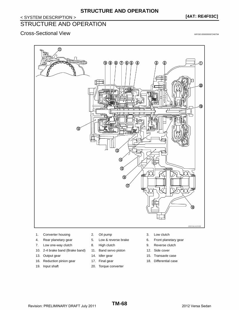
[4AT: RE4F03C]STRUCTURE AND OPERATION
< SYSTEM DESCRIPTION >
STRUCTURE AND OPERATION
Cross-Sectional View INFOID:0000000007240794
1. Converter housing 2. Oil pump 3. Low clutch
4. Rear planetary gear 5. Low & reverse brake 6. Front planetary gear
7. Low one-way clutch 8. High clutch 9. Reverse clutch
10. 2-4 brake band (Brake band) 11. Band servo piston 12. Side cover
13. Output gear 14. Idler gear 15. Transaxle case
16. Reduction pinion gear 17. Final gear 18. Differential case
19. Input shaft 20. Torque converter
JSDIA1625ZZ
TM-68Revision: PRELIMINARY DRAFT July 2011 2012 Versa Sedan
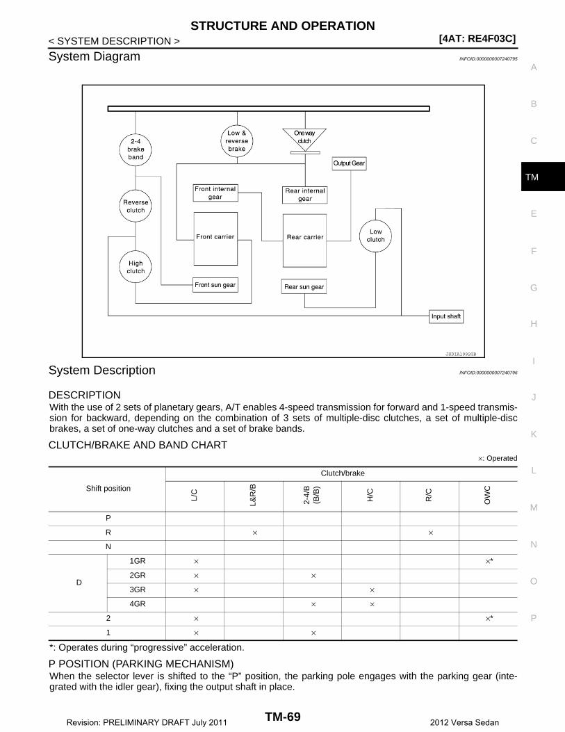
STRUCTURE AND OPERATION[4AT: RE4F03C]
C
E
F
G
H
I
J
K
L
M
A
B
M
N
O
P
< SYSTEM DESCRIPTION >
T
System Diagram INFOID:0000000007240795
System Description INFOID:0000000007240796
DESCRIPTIONWith the use of 2 sets of planetary gears, A/T enables 4-speed transmission for forward and 1-speed transmis-sion for backward, depending on the combination of 3 sets of multiple-disc clutches, a set of multiple-discbrakes, a set of one-way clutches and a set of brake bands.
CLUTCH/BRAKE AND BAND CHART×: Operated
*: Operates during “progressive” acceleration.
P POSITION (PARKING MECHANISM)When the selector lever is shifted to the “P” position, the parking pole engages with the parking gear (inte-grated with the idler gear), fixing the output shaft in place.
JSDIA1992GB
Shift position
Clutch/brake
L/C
L&R
/B
2-4/
B(B
/B)
H/C
R/C
OW
C
P
R × ×
N
D
1GR × ×*
2GR × ×
3GR × ×
4GR × ×
2 × ×*
1 × ×
TM-69Revision: PRELIMINARY DRAFT July 2011 2012 Versa Sedan
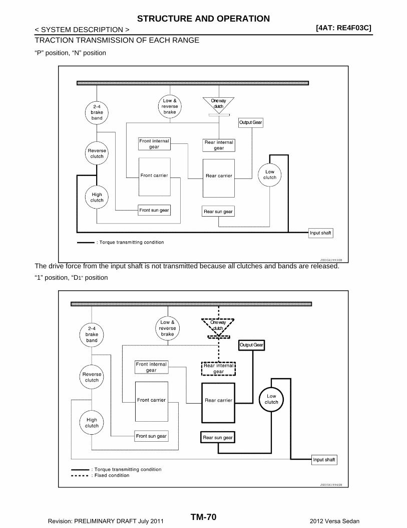
[4AT: RE4F03C]STRUCTURE AND OPERATION
< SYSTEM DESCRIPTION >
TRACTION TRANSMISSION OF EACH RANGE
“P” position, “N” position
The drive force from the input shaft is not transmitted because all clutches and bands are released.
“1” position, “D1” position
JSDIA1993GB
JSDIA1994GB
TM-70Revision: PRELIMINARY DRAFT July 2011 2012 Versa Sedan
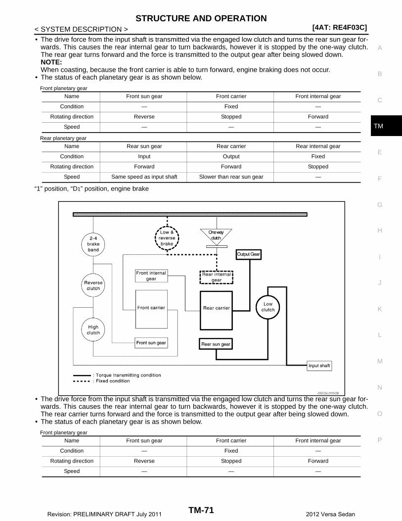
STRUCTURE AND OPERATION[4AT: RE4F03C]
C
E
F
G
H
I
J
K
L
M
A
B
M
N
O
P
< SYSTEM DESCRIPTION >
T
• The drive force from the input shaft is transmitted via the engaged low clutch and turns the rear sun gear for-wards. This causes the rear internal gear to turn backwards, however it is stopped by the one-way clutch.The rear gear turns forward and the force is transmitted to the output gear after being slowed down.NOTE:When coasting, because the front carrier is able to turn forward, engine braking does not occur.
• The status of each planetary gear is as shown below.
Front planetary gear
Rear planetary gear
“1” position, “D1” position, engine brake
• The drive force from the input shaft is transmitted via the engaged low clutch and turns the rear sun gear for-wards. This causes the rear internal gear to turn backwards, however it is stopped by the one-way clutch.The rear carrier turns forward and the force is transmitted to the output gear after being slowed down.
• The status of each planetary gear is as shown below.
Front planetary gear
Name Front sun gear Front carrier Front internal gear
Condition — Fixed —
Rotating direction Reverse Stopped Forward
Speed — — —
Name Rear sun gear Rear carrier Rear internal gear
Condition Input Output Fixed
Rotating direction Forward Forward Stopped
Speed Same speed as input shaft Slower than rear sun gear —
JSDIA1995GB
Name Front sun gear Front carrier Front internal gear
Condition — Fixed —
Rotating direction Reverse Stopped Forward
Speed — — —
TM-71Revision: PRELIMINARY DRAFT July 2011 2012 Versa Sedan

[4AT: RE4F03C]STRUCTURE AND OPERATION
< SYSTEM DESCRIPTION >Rear planetary gear
“2” position, “D2” position
• In 1st gear, the front sun gear is turning in reverse. However the 2-4 brake operates and fixes the front sungear in place. When this happens, the front carrier turns in the forward direction. As a result, when the frontinternal gear transmits force to the output gear, it turns forward at a faster speed than when in 1st gear.
• Because the rear internal gear and front carrier are turning forward, the one-way clutch turns freely.• The status of each planetary gear is as shown below.
Front planetary gear
Rear planetary gear
“D3” position
Name Rear sun gear Rear carrier Rear internal gear
Condition Input Output Fixed
Rotating direction Forward Forward Stopped
Speed Same speed as input shaft Slower than rear sun gear —
JSDIA1996GB
Name Front sun gear Front carrier Front internal gear
Condition Fixed Output Input
Rotating direction Stopped Forward Forward
Speed — Slower than front internal gear Same speed as rear carrier
Name Rear sun gear Rear carrier Rear internal gear
Condition Input Output Input
Rotating direction Forward Forward Forward
Speed Same speed as input shaft Slower than rear sun gear Slower than rear carrier
TM-72Revision: PRELIMINARY DRAFT July 2011 2012 Versa Sedan

STRUCTURE AND OPERATION[4AT: RE4F03C]
C
E
F
G
H
I
J
K
L
M
A
B
M
N
O
P
< SYSTEM DESCRIPTION >
T
• The low clutch and high clutch that are connected to the input shaft are engaged, creating a single powertransmitting mechanism and rotating while engaged.
• The status of each planetary gear is as shown below.
Front planetary gear
Rear planetary gear
“D4” position
JSDIA1997GB
Name Front sun gear Front carrier Front internal gear
Condition — Input —
Rotating direction Forward Forward Forward
Speed Same speed as input shaft Same speed as input shaft Same speed as input shaft
Name Rear sun gear Rear carrier Rear internal gear
Condition Input Output —
Rotating direction Forward Forward Forward
Speed Same speed as input shaft Same speed as input shaft Same speed as input shaft
TM-73Revision: PRELIMINARY DRAFT July 2011 2012 Versa Sedan
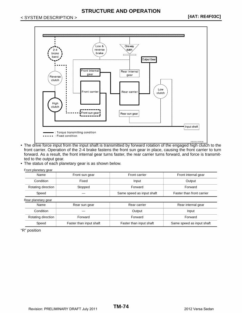
[4AT: RE4F03C]STRUCTURE AND OPERATION
< SYSTEM DESCRIPTION >
• The drive force input from the input shaft is transmitted by forward rotation of the engaged high clutch to thefront carrier. Operation of the 2-4 brake fastens the front sun gear in place, causing the front carrier to turnforward. As a result, the front internal gear turns faster, the rear carrier turns forward, and force is transmit-ted to the output gear.
• The status of each planetary gear is as shown below.
Front planetary gear
Rear planetary gear
“R” position
JSDIA1998GB
Name Front sun gear Front carrier Front internal gear
Condition Fixed Input Output
Rotating direction Stopped Forward Forward
Speed — Same speed as input shaft Faster than front carrier
Name Rear sun gear Rear carrier Rear internal gear
Condition — Output Input
Rotating direction Forward Forward Forward
Speed Faster than input shaft Faster than input shaft Same speed as input shaft
TM-74Revision: PRELIMINARY DRAFT July 2011 2012 Versa Sedan

STRUCTURE AND OPERATION[4AT: RE4F03C]
C
E
F
G
H
I
J
K
L
M
A
B
M
N
O
P
< SYSTEM DESCRIPTION >
T
• The drive force from the input shaft is transmitted by forward rotation of the engaged reverse clutch to thefront sun gear. Engagement of the low & reverse brake fastens the front carrier in place, causing the frontinternal gear to turn in reverse and transmitting force by reverse rotation to the output gear.
• The status of each planetary gear is as shown below.
Front planetary gear
Rear planetary gear
Component Description INFOID:0000000007240797
JSDIA1999GB
Name Front sun gear Front carrier Front internal gear
Condition Input Fixed Output
Rotating direction Forward Stopped Reverse
Speed Same speed as input shaft — Slower than input shaft
Name Rear sun gear Rear carrier Rear internal gear
Condition — Fixed Fixed
Rotating direction Reverse Reverse Stopped
Speed Faster than input shaft Slower than input shaft —
Name (abbreviation) FUNCTION
Torque converter Amplifies the drive force from the engine and transmits it to the transmission input shaft.
Oil pumpDriven by the engine, this component supplies oil to the torque converter, control valve assembly, and lubricated parts.
4-point gearTransmits drive force from the transmission mechanism to the output gear, idler gear, reduction gear, and final gear.
Low clutch (L/C) Connects the rear sun gear and input shaft
High clutch (H/C) Connects the front carrier and input shaft
Reverse clutch (R/C) Connects the front sun gear and input shaft
Low & reverse brake (L&R/B) Fastens the rear internal gear and front carrier in place.
2-4 brake (2-4/B) Brake band that fastens the front sun gear in place.
TM-75Revision: PRELIMINARY DRAFT July 2011 2012 Versa Sedan
[4AT: RE4F03C]STRUCTURE AND OPERATION
< SYSTEM DESCRIPTION >
One-way clutch (OWC)This clutch prevents reverse turning of the front carrier and rear internal gear. It operates not hy-draulically but mechanically.
Planetary gear Transmits drive force to various positions by engagement and release of the clutches and bands.
Name (abbreviation) FUNCTION
TM-76Revision: PRELIMINARY DRAFT July 2011 2012 Versa Sedan
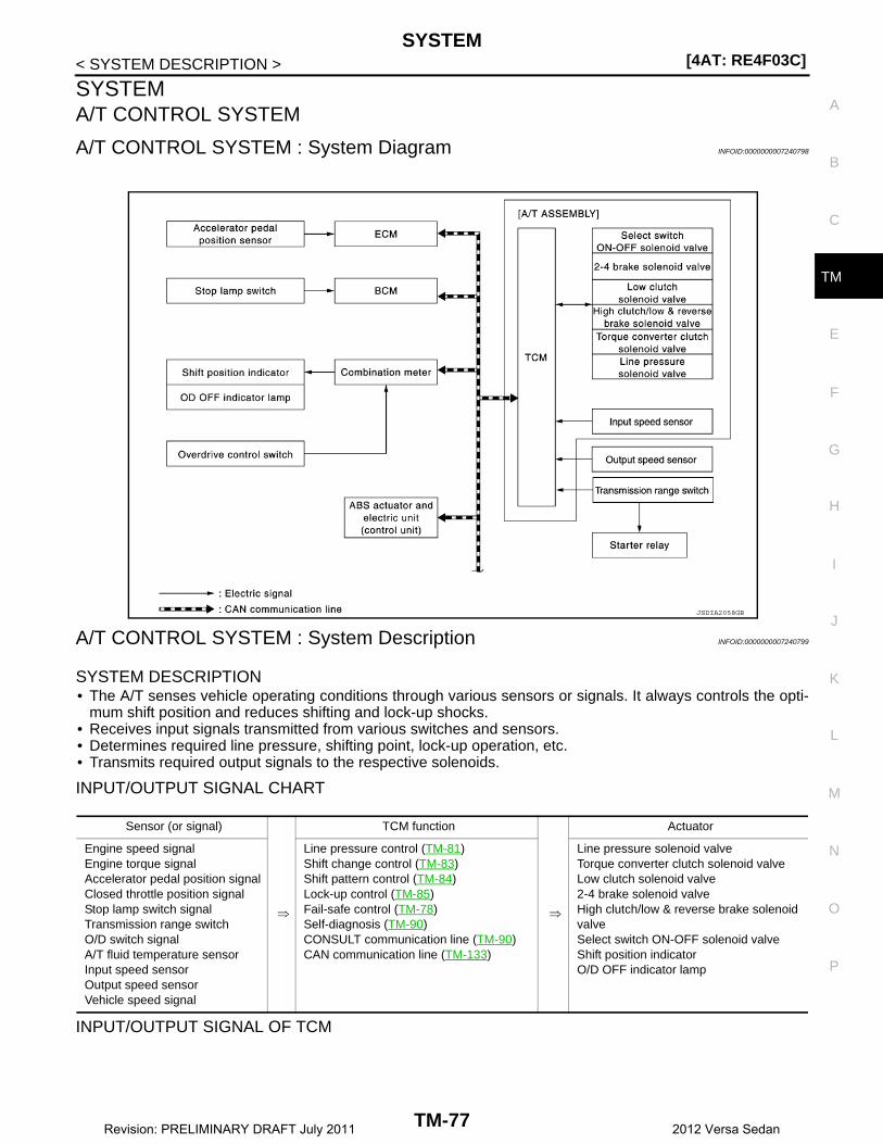
SYSTEM[4AT: RE4F03C]
C
E
F
G
H
I
J
K
L
M
A
B
M
N
O
P
< SYSTEM DESCRIPTION >
T
SYSTEMA/T CONTROL SYSTEM
A/T CONTROL SYSTEM : System Diagram INFOID:0000000007240798
A/T CONTROL SYSTEM : System Description INFOID:0000000007240799
SYSTEM DESCRIPTION• The A/T senses vehicle operating conditions through various sensors or signals. It always controls the opti-
mum shift position and reduces shifting and lock-up shocks.• Receives input signals transmitted from various switches and sensors.• Determines required line pressure, shifting point, lock-up operation, etc.• Transmits required output signals to the respective solenoids.
INPUT/OUTPUT SIGNAL CHART
INPUT/OUTPUT SIGNAL OF TCM
JSDIA2058GB
Sensor (or signal)
⇒
TCM function
⇒
Actuator
Engine speed signalEngine torque signalAccelerator pedal position signalClosed throttle position signalStop lamp switch signalTransmission range switchO/D switch signalA/T fluid temperature sensorInput speed sensorOutput speed sensorVehicle speed signal
Line pressure control (TM-81)Shift change control (TM-83)Shift pattern control (TM-84)Lock-up control (TM-85)Fail-safe control (TM-78)Self-diagnosis (TM-90)CONSULT communication line (TM-90)CAN communication line (TM-133)
Line pressure solenoid valveTorque converter clutch solenoid valveLow clutch solenoid valve 2-4 brake solenoid valveHigh clutch/low & reverse brake solenoid valveSelect switch ON-OFF solenoid valve Shift position indicatorO/D OFF indicator lamp
TM-77Revision: PRELIMINARY DRAFT July 2011 2012 Versa Sedan

[4AT: RE4F03C]SYSTEM
< SYSTEM DESCRIPTION >
*: If these input and output signals are different, the TCM triggers the fail-safe function.
A/T CONTROL SYSTEM : Fail-Safe INFOID:0000000007240800
TCM is equipped with an electrical fail-safe mode. The operation can be continued even if the signal circuit ofthe main electronically controlled input/output parts are damaged.If the vehicle shows following behaviors including “poor acceleration”, a malfunction of the applicable systemis detected by TCM and the vehicle may be in a fail-safe mode. At this time, check the DTC code and performinspection and repair according to the malfunction diagnosis procedures.
FAIL-SAFE FUNCTION
Control itemLine
pressure control
Shift change control
Shift pattern control
Lock-up con-trol
Fail-safe func-
tion*
Input
Engine speed signal(CAN communication line)
X X X X X
Engine torque signal(CAN communication line)
X X
Accelerator pedal position signal (CAN communication line)
X X X X X
Closed throttle position signal(CAN communication line)
X X X X
Stop lamp switch signal(CAN communication line)
X X X X
Transmission range switch X X X X X
O/D switch signal(CAN communication line)
X
A/T fluid temperature sensor X X X X X
Input speed sensor X X X X
Output pressure sensor X X X X X
Output
Line pressure solenoid valve X X X
Torque converter clutch solenoid valve
X X X
Low clutch solenoid valve X X
2-4 brake solenoid valve X X
High clutch/low & reverse brake sole-noid valve
X X
Select switch ON-OFF solenoid valve X X
Shift position indicator(CAN communication line)
X
O/D OFF indicator lamp(CAN communication line)
X
DTC Vehicle behavior Vehicle condition
P0705P0706
• “D” position (The shifting can be performed)• “R” position can be performed• Back-up lamp is OFF• Large shift shock• Lock-up is prohibited• Slip lock-up is prohibited
—
P0713The gear is fixed in a position of error detection During driving
Locks in 3GR Other than the above
TM-78Revision: PRELIMINARY DRAFT July 2011 2012 Versa Sedan
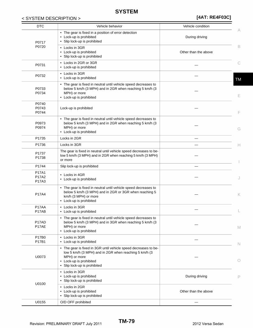
SYSTEM[4AT: RE4F03C]
C
E
F
G
H
I
J
K
L
M
A
B
M
N
O
P
< SYSTEM DESCRIPTION >
T
P0717P0720
• The gear is fixed in a position of error detection• Lock-up is prohibited• Slip lock-up is prohibited
During driving
• Locks in 3GR• Lock-up is prohibited• Slip lock-up is prohibited
Other than the above
P0731• Locks in 2GR or 3GR• Lock-up is prohibited
—
P0732• Locks in 3GR• Lock-up is prohibited
—
P0733P0734
• The gear is fixed in neutral until vehicle speed decreases to below 5 km/h (3 MPH) and in 2GR when reaching 5 km/h (3 MPH) or more
• Lock-up is prohibited
—
P0740P0743P0744
Lock-up is prohibited —
P0973P0974
• The gear is fixed in neutral until vehicle speed decreases to below 5 km/h (3 MPH) and in 2GR when reaching 5 km/h (3 MPH) or more
• Lock-up is prohibited
—
P1735 Locks in 2GR —
P1736 Locks in 3GR —
P1737P1738
The gear is fixed in neutral until vehicle speed decreases to be-low 5 km/h (3 MPH) and in 2GR when reaching 5 km/h (3 MPH) or more
—
P1744 Slip lock-up is prohibited —
P17A1P17A2P17A3
• Locks in 4GR• Lock-up is prohibited
—
P17A4
• The gear is fixed in neutral until vehicle speed decreases to below 5 km/h (3 MPH) and in 2GR or 3GR when reaching 5 km/h (3 MPH) or more
• Lock-up is prohibited
—
P17AAP17AB
• Locks in 3GR• Lock-up is prohibited
—
P17ADP17AE
• The gear is fixed in neutral until vehicle speed decreases to below 5 km/h (3 MPH) and in 3GR when reaching 5 km/h (3 MPH) or more
• Lock-up is prohibited
—
P17B0P17B1
• Locks in 3GR• Lock-up is prohibited
—
U0073
• The gear is fixed in 3GR until vehicle speed decreases to be-low 5 km/h (3 MPH) and in 2GR when reaching 5 km/h (3 MPH) or more
• Lock-up is prohibited• Slip lock-up is prohibited
—
U0100
• Locks in 3GR• Lock-up is prohibited• Slip lock-up is prohibited
During driving
• Locks in 2GR• Lock-up is prohibited• Slip lock-up is prohibited
Other than the above
U0155 O/D OFF prohibited —
DTC Vehicle behavior Vehicle condition
TM-79Revision: PRELIMINARY DRAFT July 2011 2012 Versa Sedan

[4AT: RE4F03C]SYSTEM
< SYSTEM DESCRIPTION >
A/T CONTROL SYSTEM : Protection Control INFOID:0000000007240801
The TCM becomes the protection control status temporarily to protect the safety when the safety of TCM andtransmission is lost. It automatically returns to the normal status if the safety is secured.The TCM is equipped with the following protection control.
REVERSE INHIBIT CONTROLIntercepts the torque transmission and shifts to the neutral status if the selector lever is shifted to “R” positionwhile the vehicle moves forward at the vehicle speed 10 km/h (7 MPH) or more.
TCM HIGH TEMPERATURE PROTECTION CONTROLWhen the ATF becomes hot, the shifting pattern is changed for preventing fluid temperature rise.
TORQUE-DOWN CONTROL WHEN CONTINUOUS STALL OCCURS IN D POSITIONIf the accelerator pedal is continually depressed for a certain length of time when the selector lever is in the “D”position and the vehicle is parked, the engine output is limited for protecting the transaxle.
O/D PROHIBIT CONTROL AT LOW TEMPERATURESWhen the ATF temperature is low immediately after engine start, shifting to 4GR is prohibited for protecting thetransaxle and allowing the exhaust gas characteristics to warm up quickly.
U0300
• Locks in 3GR• Lock-up is prohibited• Slip lock-up is prohibited
During driving
• Locks in 2GR• Lock-up is prohibited• Slip lock-up is prohibited
Other than the above
DTC Vehicle behavior Vehicle condition
Operation detection conditions• Vehicle speed: 10 km/h (7 MPH) or more (when driving forward)• Selector lever is shifted to “R” position.
Control when activated Neutral
Recovery condition• Vehicle speed: 7 km/h (4 MPH) or less
and• Engine speed: 2,800 rpm or less
Vehicle behavior• The torque transmission cannot be performed• There is a shock just before a vehicle stop
Operation detection conditions ATF temp.: 125°C (257°F) or more
Control when activated Change the shift pattern so that higher upshift may be achieved.
Recovery condition • ATF temp.: 119°C (246°F) or less
Vehicle behavior Upshifts at a higher vehicle speed than usual.
Operation detection conditions
The following conditions continue for 20 seconds or more• Selector lever is in the “D” position or “R” position and the vehicle is stopped
and• Engine speed: 2,300 – 2,850 rpm
Control when activated Limits engine output
Recovery condition• Selector lever is shifted to a position other than “D” or “R”
or• The accelerator pedal is released
Vehicle behavior• Decreased starting performance• Engine speed hunching when the accelerator pedal is depressed
TM-80Revision: PRELIMINARY DRAFT July 2011 2012 Versa Sedan
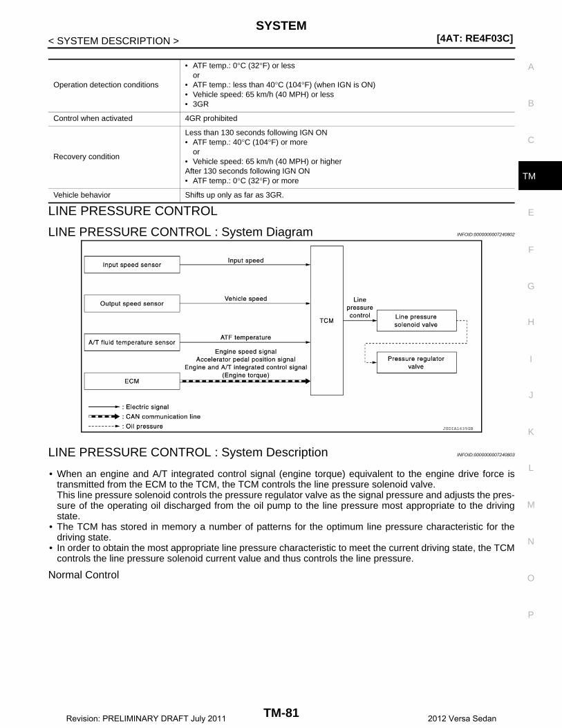
SYSTEM[4AT: RE4F03C]
C
E
F
G
H
I
J
K
L
M
A
B
M
N
O
P
< SYSTEM DESCRIPTION >
T
LINE PRESSURE CONTROL
LINE PRESSURE CONTROL : System Diagram INFOID:0000000007240802
LINE PRESSURE CONTROL : System Description INFOID:0000000007240803
• When an engine and A/T integrated control signal (engine torque) equivalent to the engine drive force istransmitted from the ECM to the TCM, the TCM controls the line pressure solenoid valve.This line pressure solenoid controls the pressure regulator valve as the signal pressure and adjusts the pres-sure of the operating oil discharged from the oil pump to the line pressure most appropriate to the drivingstate.
• The TCM has stored in memory a number of patterns for the optimum line pressure characteristic for thedriving state.
• In order to obtain the most appropriate line pressure characteristic to meet the current driving state, the TCMcontrols the line pressure solenoid current value and thus controls the line pressure.
Normal Control
Operation detection conditions
• ATF temp.: 0°C (32°F) or lessor
• ATF temp.: less than 40°C (104°F) (when IGN is ON)• Vehicle speed: 65 km/h (40 MPH) or less• 3GR
Control when activated 4GR prohibited
Recovery condition
Less than 130 seconds following IGN ON• ATF temp.: 40°C (104°F) or more
or• Vehicle speed: 65 km/h (40 MPH) or higherAfter 130 seconds following IGN ON• ATF temp.: 0°C (32°F) or more
Vehicle behavior Shifts up only as far as 3GR.
JSDIA1635GB
TM-81Revision: PRELIMINARY DRAFT July 2011 2012 Versa Sedan

[4AT: RE4F03C]SYSTEM
< SYSTEM DESCRIPTION >Each clutch is adjusted to the necessary pressure to match theengine drive force.
Back-up Control (Engine Brake)When the select operation is performed during driving and the A/T isshifted down, the line pressure is set according to the vehicle speed.
During Shift ChangeThe necessary and adequate line pressure for shift change is set.For this reason, line pressure pattern setting corresponds to enginetorque and gearshift selection. Also, line pressure characteristic cor-responds to engine speed, during engine brake operation.
At Low Fluid Temperature
PCIA0008E
PCIA0009E
PCIA0010E
TM-82Revision: PRELIMINARY DRAFT July 2011 2012 Versa Sedan
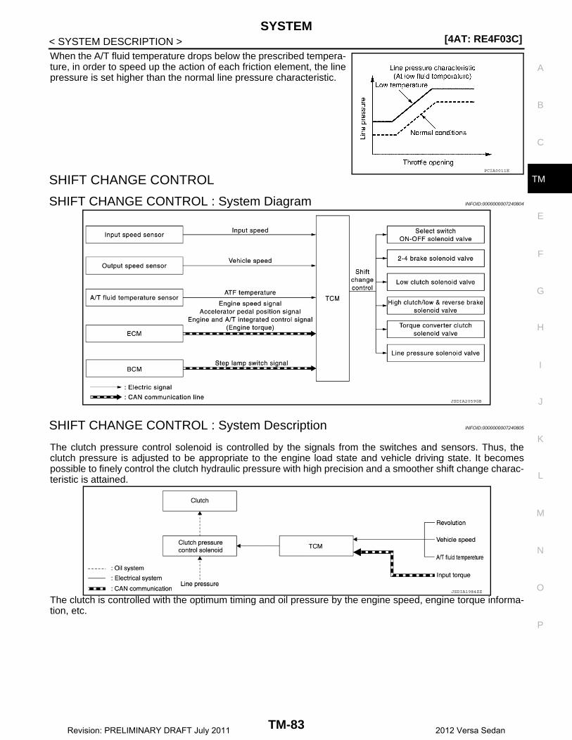
SYSTEM[4AT: RE4F03C]
C
E
F
G
H
I
J
K
L
M
A
B
M
N
O
P
< SYSTEM DESCRIPTION >
T
When the A/T fluid temperature drops below the prescribed tempera-ture, in order to speed up the action of each friction element, the linepressure is set higher than the normal line pressure characteristic.
SHIFT CHANGE CONTROL
SHIFT CHANGE CONTROL : System Diagram INFOID:0000000007240804
SHIFT CHANGE CONTROL : System Description INFOID:0000000007240805
The clutch pressure control solenoid is controlled by the signals from the switches and sensors. Thus, theclutch pressure is adjusted to be appropriate to the engine load state and vehicle driving state. It becomespossible to finely control the clutch hydraulic pressure with high precision and a smoother shift change charac-teristic is attained.
The clutch is controlled with the optimum timing and oil pressure by the engine speed, engine torque informa-tion, etc.
PCIA0011E
JSDIA2059GB
JSDIA1984ZZ
TM-83Revision: PRELIMINARY DRAFT July 2011 2012 Versa Sedan

[4AT: RE4F03C]SYSTEM
< SYSTEM DESCRIPTION >Shift Change System Diagram
*1: Full phase real-time feedback control monitors movement of gear ratio at gear change, and controls oilpressure in real-time to achieve the best gear ratio.SHIFT PATTERN CONTROL
SHIFT PATTERN CONTROL : System Diagram INFOID:0000000007240806
SHIFT PATTERN CONTROL : System Description INFOID:0000000007240807
Shift pattern control automatically selects the shift pattern (such as road environment and driving style) suit-able for the various situations so as to allow the vehicle to be driven efficiently and smoothly.LOCK-UP CONTROL
JSDIA1637GB
JSDIA1636GB
TM-84Revision: PRELIMINARY DRAFT July 2011 2012 Versa Sedan
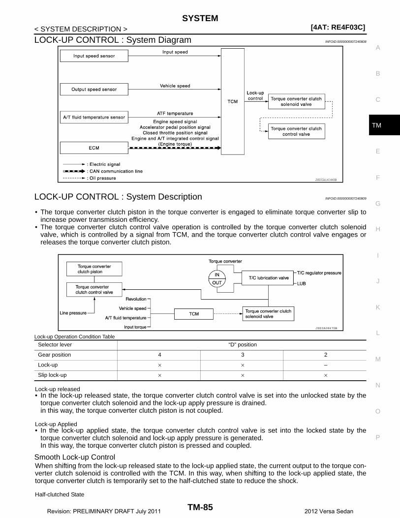
SYSTEM[4AT: RE4F03C]
C
E
F
G
H
I
J
K
L
M
A
B
M
N
O
P
< SYSTEM DESCRIPTION >
T
LOCK-UP CONTROL : System Diagram INFOID:0000000007240808
LOCK-UP CONTROL : System Description INFOID:0000000007240809
• The torque converter clutch piston in the torque converter is engaged to eliminate torque converter slip toincrease power transmission efficiency.
• The torque converter clutch control valve operation is controlled by the torque converter clutch solenoidvalve, which is controlled by a signal from TCM, and the torque converter clutch control valve engages orreleases the torque converter clutch piston.
Lock-up Operation Condition Table
Lock-up released• In the lock-up released state, the torque converter clutch control valve is set into the unlocked state by the
torque converter clutch solenoid and the lock-up apply pressure is drained.in this way, the torque converter clutch piston is not coupled.
Lock-up Applied• In the lock-up applied state, the torque converter clutch control valve is set into the locked state by the
torque converter clutch solenoid and lock-up apply pressure is generated.In this way, the torque converter clutch piston is pressed and coupled.
Smooth Lock-up ControlWhen shifting from the lock-up released state to the lock-up applied state, the current output to the torque con-verter clutch solenoid is controlled with the TCM. In this way, when shifting to the lock-up applied state, thetorque converter clutch is temporarily set to the half-clutched state to reduce the shock.
Half-clutched State
JSDIA1638GB
JSDIA0847GB
Selector lever “D” position
Gear position 4 3 2
Lock-up × × –
Slip lock-up × × ×
TM-85Revision: PRELIMINARY DRAFT July 2011 2012 Versa Sedan

[4AT: RE4F03C]SYSTEM
< SYSTEM DESCRIPTION >• The current output from the TCM to the torque converter clutch solenoid is varied to steadily increase the
torque converter clutch solenoid pressure.In this way, the lock-up apply pressure gradually rises and while the torque converter clutch piston is put intohalf-clutched states, the torque converter clutch piston operating pressure is increased and the coupling iscompleted smoothly.
Slip Lock-up Control• In the slip region, the torque converter clutch solenoid current is controlled with the TCM to put it into the
half-clutched state. This absorbs the engine torque fluctuation and lock-up operates from low speed.This raises the fuel efficiency for 2GR, 3GR,and 4GR.
SHIFT LOCK SYSTEM
SHIFT LOCK SYSTEM : System Description INFOID:0000000007240810
The selector lever cannot be shifted from “P” position to any other position unless the ignition switch is in theON position and the brake pedal is depressed.KEY LOCK SYSTEM
KEY LOCK SYSTEM : System Description INFOID:0000000007240811
• The key lock mechanism also operates as a shift lock:With the ignition switch turned to ON, selector lever cannot be shifted from “P” position to any other positionunless brake pedal is depressed.With the key removed, selector lever cannot be shifted from “P” position to any other position.The key cannot be removed unless selector lever is placed in “P” position.
• The shift lock and key lock mechanisms are controlled by the ON-OFF operation of the shift lock solenoidand by the operation of the rotator and slider located inside key cylinder, respectively.
TM-86Revision: PRELIMINARY DRAFT July 2011 2012 Versa Sedan
ON BOARD DIAGNOSTIC (OBD) SYSTEM[4AT: RE4F03C]
C
E
F
G
H
I
J
K
L
M
A
B
M
N
O
P
< SYSTEM DESCRIPTION >
T
ON BOARD DIAGNOSTIC (OBD) SYSTEM
Description INFOID:0000000007240812
This system is an on board diagnostic system that records exhaust emission-related diagnostic informationand detects a sensors/actuator-related malfunction. A malfunction is indicated by the malfunction indicatorlamp (MIL) and stored in ECU memory as a DTC. The diagnostic information can be obtained with the diag-nostic tool (GST: Generic Scan Tool).
OBD FUNCTION INFOID:0000000007240813
When GST is connected with a data link connector equipped on the vehicle side, it will communicate with thecontrol unit equipped in the vehicle and then enable various kinds of diagnostic tests. Refer to TM-87,"Description".NOTE:Service $0A is not applied for regions where it is not mandated.
TM-87Revision: PRELIMINARY DRAFT July 2011 2012 Versa Sedan

[4AT: RE4F03C]DIAGNOSIS SYSTEM (TCM)
< SYSTEM DESCRIPTION >
DIAGNOSIS SYSTEM (TCM)DIAGNOSIS DESCRIPTION
DIAGNOSIS DESCRIPTION : 1 Trip Detection Diagnosis and 2 Trip Detection Diagno-sis INFOID:0000000007797917
NOTE:“Start the engine and turn OFF the ignition switch after warm-up.” This is defined as 1 trip.
1 TRIP DETECTION DIAGNOSISWhen initial malfunction is detected, TCM memorizes DTC. In these diagnoses, some illuminate MIL andsome do not. Refer to TM-106, "DTC Index".
2 TRIP DETECTION DIAGNOSISWhen initial malfunction is detected, TCM memorizes DTC of the 1st trip. MIL does not light at this stage. <1trip>If the same malfunction is detected again in next driving, TCM memorizes DTC. When DTC is memorized, MILlights. <2 trip>“Trip” of the “2 trip detection diagnosis” indicates the driving mode that executes self-diagnosis during driving.
×: Check possible —: Check not possible
DIAGNOSIS DESCRIPTION : DTC and DTC of 1st Trip INFOID:0000000007797918
2 TRIP DETECTION DIAGNOSIS THAT ILLUMINATES MIL• The DTC number of the 1st trip is the same as the DTC number.• When a malfunction is detected at the 1st trip, TCM memorizes DTC of the 1st trip. MIL does not light at this
stage. If the same malfunction is not detected at the 2nd trip (conforming to necessary driving conditions),DTC at the 1st trip is erased from TCM. If the same malfunction is detected at the 2nd trip, TCM memorizesDTC and MIL lights at the same time.
• The DTC of the 1st trip is specified in Service $01 of SAE J1979/ISO 15031-5. Since detection of DTC at the1st trip does not illuminate MIL, warning for a problem is not given to a driver.
• For procedure to delete DTC and 1st trip DTC from TCM, refer to TM-90, "CONSULT Function (TRANSMIS-SION)".
• If DTC of the 1st trip is detected, it is necessary to check the cause according to the “Diagnosis flow”. Referto TM-116, "Diagnosis Flow".
DIAGNOSIS DESCRIPTION : Malfunction Indicator Lamp (MIL) INFOID:0000000007797919
• TCM not only detects DTC, but also sends the MIL signal to ECM through CAN communication. ECM sendsthe MIL signal to the combination meter through CAN communication according to the signal, and illumi-nates MIL.
• For malfunction indicator lamp (MIL) description, refer to EC-46, "DIAGNOSIS DESCRIPTION : MalfunctionIndicator (MI)".
DIAGNOSIS DESCRIPTION : Counter System INFOID:0000000007797920
RELATION BETWEEN DTC AT 1ST TRIP/DTC/MI AND DRIVING CONDITIONS (FOR 2 TRIP DE-TECTION DIAGNOSIS THAT ILLUMINATES MIL)• When initial malfunction is detected, TCM memorizes DTC of the 1st trip. MIL does not light at this stage.• If the same malfunction is detected at the 2nd trip, TCM memorizes DTC and MIL lights at the same time.• Then, MIL goes after driving the vehicle for 3 trips under “Driving Pattern B” without malfunction.
Item
DTC at the 1st trip DTC MIL
Display at the 1st trip
Display at the 2nd trip
Display at the 1st trip
Display at the 2nd trip
Illumination at the 1st trip
Illumination at the 2nd trip
1 trip detection diagnosis(Refer to TM-106, "DTC Index")
— — × — × —
2 trip detection diagnosis(Refer to TM-106, "DTC Index")
× — — × — ×
TM-88Revision: PRELIMINARY DRAFT July 2011 2012 Versa Sedan

DIAGNOSIS SYSTEM (TCM)[4AT: RE4F03C]
C
E
F
G
H
I
J
K
L
M
A
B
M
N
O
P
< SYSTEM DESCRIPTION >
T
• DTC is displayed until 40 trips of “Driving Pattern A” are satisfied without detecting the same malfunction.DTC is erased when 40 trips are satisfied.
• When the self-diagnosis result is acceptable at the 2nd trip (conforming to driving pattern B), DTC of the 1sttrip is erased.
COUNTER SYSTEM LIST
DRIVING CONDITION
Driving Pattern ADriving pattern A is the driving condition that provides warm-up.In specific, count-up is performed when all of the following conditions are satisfied.• Engine speed reaches 400 rpm or more.• Engine coolant temperature rises by 20°C (36°F) or more after starting the engine.• Engine coolant temperature reaches 70°C (158°F) or more.• The ignition switch is turned from ON to OFF.NOTE:• If the same malfunction is detected regardless of the driving condition, reset the A counter.• When the above is satisfied without detecting the same malfunction, count up the A counter.• When MIL goes off due to the malfunction and the A counter reaches 40, the DTC is erased.
Driving Pattern BDriving pattern B is the driving condition that performs all diagnoses once.In specific, count-up is performed when all of the following conditions are satisfied.• Engine speed reaches 400 rpm or more.• Engine coolant temperature reaches 70°C (158°F) or more.• Vehicle speed of 70 – 120 km/h (44 – 75 MPH) is maintained for 60 seconds or more under the control of
closed loop.• Vehicle speed of 30 – 60 km/h (19 – 37 MPH) is maintained for 10 seconds or more under the control of
closed loop.• Under the closed loop control condition, the following state reaches 12 seconds or more in total: Vehicle
speed of 4 km/h (2 MPH) or less with idling condition.• A lapse of 22 minutes or more after engine start.• The state of driving at 10km/h (6 MPH) or more reaches 10 minutes or more in total.• The ignition switch was changed from ON to OFF.NOTE:• If the same malfunction is detected regardless of the driving condition, reset the B counter.• When the above is satisfied without detecting the same malfunction, count up the B counter.• When the B counter reaches 3 without malfunction, MIL goes off.• When the B counter is counted once without detecting the same malfunction after TCM memorizes DTC of
the 1st trip, DTC of the 1st trip is erased.
Item Driving pattern Trip
MIL (OFF) B 3
DTC (clear) A 40
DTC at 1st trip (clear) B 1
TM-89Revision: PRELIMINARY DRAFT July 2011 2012 Versa Sedan
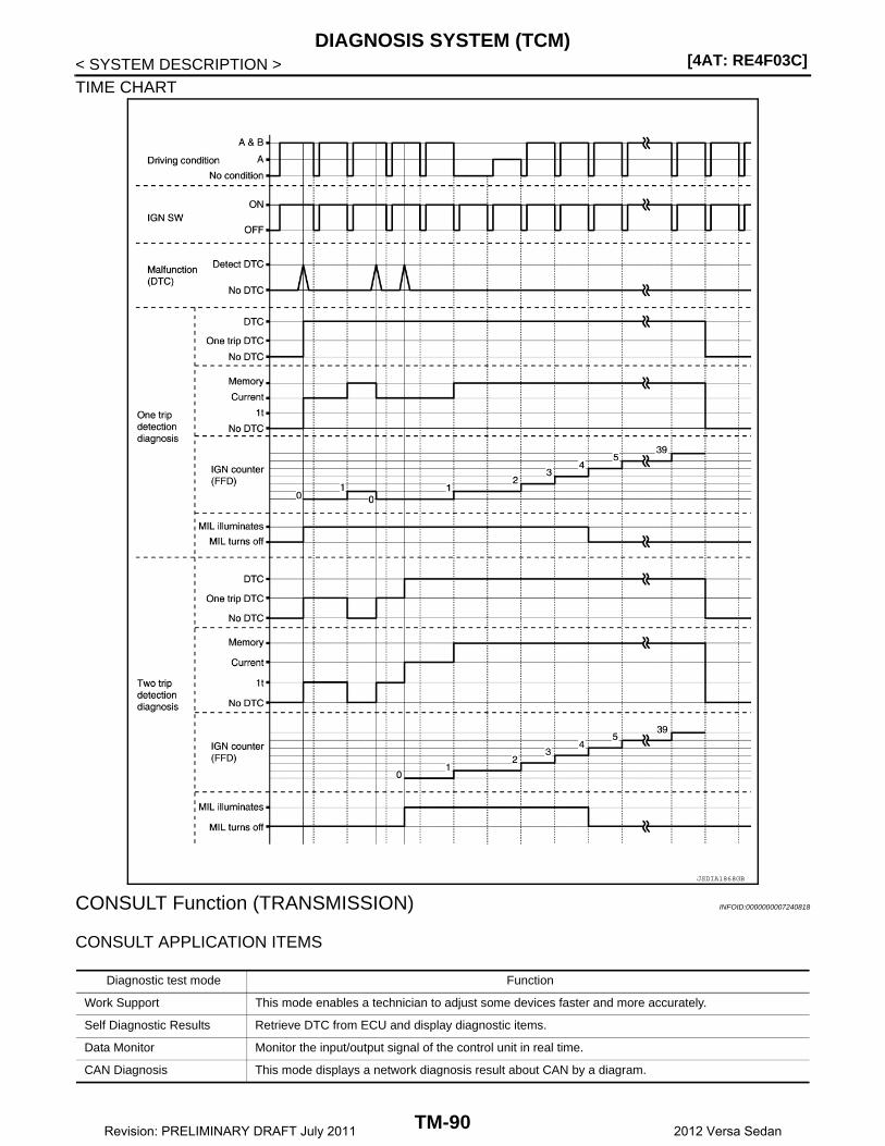
[4AT: RE4F03C]DIAGNOSIS SYSTEM (TCM)
< SYSTEM DESCRIPTION >
TIME CHART
CONSULT Function (TRANSMISSION) INFOID:0000000007240818
CONSULT APPLICATION ITEMS
JSDIA1868GB
Diagnostic test mode Function
Work Support This mode enables a technician to adjust some devices faster and more accurately.
Self Diagnostic Results Retrieve DTC from ECU and display diagnostic items.
Data Monitor Monitor the input/output signal of the control unit in real time.
CAN Diagnosis This mode displays a network diagnosis result about CAN by a diagram.
TM-90Revision: PRELIMINARY DRAFT July 2011 2012 Versa Sedan
DIAGNOSIS SYSTEM (TCM)[4AT: RE4F03C]
C
E
F
G
H
I
J
K
L
M
A
B
M
N
O
P
< SYSTEM DESCRIPTION >
T*: Although “Function Test” and “Special Function” are selectable, do not use its.
WORK SUPPORT
Display Items List
SELF DIAGNOSTIC RESULTSRefer to TM-106, "DTC Index".
DTC at 1st trip and method to read DTC• DTC (P0705, P0711, P0720, etc.) is specified by SAE J2012/ISO 15031-6. • DTC and DTC at 1st trip are displayed on “Self Diagnostic results” of CONSULT. “ Timing” shows current
malfunction or malfunction in the past. If current DTC is detected, “timing” is “present”. If the “timing” is “memorized”, it is the malfunction occurredin the past. According to “ignition counter” in “FFD”, the number (trip) of operation without malfunction of theDTC can be checked.
• When the DTC at the 1st trip is detected, the “timing” is displayed as “1t”.
DTC deletion method NOTE:If the ignition switch is left ON after repair, turn OFF the ignition switch and wait for 10 seconds or more. Then,turn ignition ON again. (Engine stop)1. Touch “TRANSMISSION” of CONSULT. 2. Touch “Self Diagnostic Result”. 3. Touch “Erase”. (DTC memorized in TCM is erased.)
IGN counterThe ignition counter is displayed in “FFD” and the number of times of satisfied “Driving Pattern A” is displayedafter normal recovery of DTC. Refer to XX-XX, "*****".• If malfunction (DTC) is currently detected, “0” is displayed. • After normal recovery, every time “Driving Pattern A” is satisfied, the display value increases from 1 → 2 →
3...38 → 39. • When MIL turns OFF due to the malfunction and the counter reaches 40, the DTC is erased.
NOTE:The counter display of “40” cannot be checked.
DATA MONITOR
Display Items List
CAN Diagnostic Support Monitor
It monitors the starts of CAN communication.
DTC & SRT confirmation The status of system monitoring tests and the self-diagnosis status/result can be confirmed.
ECU Identification Display the ECU identification number (part number etc.) of the selected system.
Function Test*This mode can show results of self-diagnosis of ECU with either “OK” or “NG”. For engine, more prac-tical tests regarding sensors/switches and/or actuators are available.
Special Function* Other results or histories, etc. that are recorded in ECU are displayed.
Diagnostic test mode Function
Item name Description
ERASE CALIBRATION DATA Erases the “CALIBRATION DATA” stored by the TCM.
ERASE LEARNING VALUE Erases the “LEARNING VALUE” stored by the TCM.
ERASE MEMORY DATA Erases both the “CALIBRATION DATA” and “LEARNING VALUE”.
TM-91Revision: PRELIMINARY DRAFT July 2011 2012 Versa Sedan

[4AT: RE4F03C]DIAGNOSIS SYSTEM (TCM)
< SYSTEM DESCRIPTION >
X: Standard, —: Not applicable, : Option
Monitored item (Unit)
Monitor Item Selection
RemarksECU IN-PUT SIG-
NALS
MAIN SIG-NALS
SELEC-TION FROM ITEM
VHCL/S SE-A/T (km/h or mph) X XDisplays the vehicle speed calculated by the TCM from the output shaft revolution.
ESTM VSP SIG (km/h or mph) X —Displays the vehicle speed signal received via CAN communication.
THROTTLE POSI (0.0/8) X —Displays the throttle position received via CAN communication.
ACCELE POSI (0.0/8) X XDisplays the accelerator position estimated val-ue received via CAN communication.
CLSD THL POS (On/Off) X —Displays the reception status of idle switch sig-nal received via CAN communication.
W/O THL POS (On/Off) X —Displays the kick down condition signal status received via CAN communication.
BRAKESW (On/Off) X —Displays the reception status of stop lamp switch signal received via CAN communication.
ENGINE SPEED (rpm) X XDisplays the engine speed received via CAN communication.
INPUT SPEED (rpm) X XDisplays the input speed calculated from low clutch dram revolution.
OUTPUT REV (rpm) X XDisplays the output speed calculated from the pulse signal of output speed sensor.
FLUID TEMP (°C or °F) X XDisplays the ATF temperature of oil pan calcu-lated from the signal voltage of A/T fluid tem-perature sensor.
BATTERY VOLT (V) X — Displays the power supply voltage of TCM.
RANGE SW 1 (On/Off) X —
Displays the operation status of transmission range switch.
RANGE SW 2 (On/Off) X —
RANGE SW D (On/Off) X —
RANGE SW N (On/Off) X —
RANGE SW R (On/Off) X —
RANGE SW P (On/Off) X —
OD CONT SW (On/Off) X —Displays the reception status of overdrive con-trol switch signal received via CAN communica-tion.
POWERSHIFT SW (On/Off) X —
• Displays the reception status of POWER mode signal received via CAN communica-tion.
• Not mounted but displayed.
ABS SIGNAL (On/Off) X —Displays the reception status of ABS operation signal received via CAN communication.
GEAR — XDisplays the current transmission gear position recognized by TCM.
TC SLIP SPEED (rpm) — XDisplays the revolution difference between in-put speed and engine speed.
GEAR RATIO — XDisplays the gear ratio calculated from input speed and output speed.
SLCT LVR POSI — X Displays the shift positions recognized by TCM.
TM-92Revision: PRELIMINARY DRAFT July 2011 2012 Versa Sedan
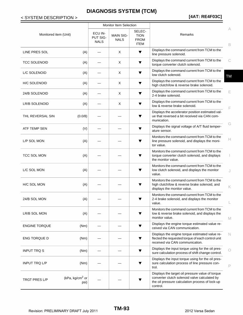
DIAGNOSIS SYSTEM (TCM)[4AT: RE4F03C]
C
E
F
G
H
I
J
K
L
M
A
B
M
N
O
P
< SYSTEM DESCRIPTION >
T
LINE PRES SOL (A) — XDisplays the command current from TCM to the line pressure solenoid.
TCC SOLENOID (A) — XDisplays the command current from TCM to the torque converter clutch solenoid.
L/C SOLENOID (A) — XDisplays the command current from TCM to the low clutch solenoid.
H/C SOLENOID (A) — XDisplays the command current from TCM to the high clutch/low & reverse brake solenoid.
24/B SOLENOID (A) — XDisplays the command current from TCM to the 2-4 brake solenoid.
LR/B SOLENOID (A) — XDisplays the command current from TCM to the low & reverse brake solenoid.
THL REVERSAL SIN (0.0/8) — —Displays the accelerator position estimated val-ue that reversed a bit received via CAN com-munication.
ATF TEMP SEN (V) — —Displays the signal voltage of A/T fluid temper-ature sensor.
L/P SOL MON (A) — —Monitors the command current from TCM to the line pressure solenoid, and displays the moni-tor value.
TCC SOL MON (A) — —Monitors the command current from TCM to the torque converter clutch solenoid, and displays the monitor value.
L/C SOL MON (A) — —Monitors the command current from TCM to the low clutch solenoid, and displays the monitor value.
H/C SOL MON (A) — —Monitors the command current from TCM to the high clutch/low & reverse brake solenoid, and displays the monitor value.
24/B SOL MON (A) — —Monitors the command current from TCM to the 2-4 brake solenoid, and displays the monitor value.
LR/B SOL MON (A) — —Monitors the command current from TCM to the low & reverse brake solenoid, and displays the monitor value.
ENGINE TORQUE (Nm) — —Displays the engine torque estimated value re-ceived via CAN communication.
ENG TORQUE D (Nm) — —Displays the engine torque estimated value re-flected the requested torque of each control unit received via CAN communication.
INPUT TRQ S (Nm) — —Displays the input torque using for the oil pres-sure calculation process of shift change control.
INPUT TRQ L/P (Nm) — —Displays the input torque using for the oil pres-sure calculation process of line pressure con-trol.
TRGT PRES L/P (kPa, kg/cm2 orpsi)
— —
Displays the target oil pressure value of torque converter clutch solenoid valve calculated by the oil pressure calculation process of lock-up control.
Monitored item (Unit)
Monitor Item Selection
RemarksECU IN-PUT SIG-
NALS
MAIN SIG-NALS
SELEC-TION
FROM ITEM
TM-93Revision: PRELIMINARY DRAFT July 2011 2012 Versa Sedan

[4AT: RE4F03C]DIAGNOSIS SYSTEM (TCM)
< SYSTEM DESCRIPTION >
TRGT PRES TCC (kPa, kg/cm2 orpsi)
— —
Displays the target oil pressure value of torque converter clutch solenoid valve calculated by the oil pressure calculation process of lock-up control.
TRGT PRES L/C (kPa, kg/cm2 orpsi)
— —Displays the target oil pressure value of low clutch solenoid valve calculated by the oil pres-sure calculation process of shift change control.
TRGT PRES H/C (kPa, kg/cm2 orpsi)
— —
Displays the target oil pressure value of high clutch/low & reverse brake solenoid valve cal-culated by the oil pressure calculation process of shift change control.
TRG PRES 24/B (kPa, kg/cm2 orpsi)
— —Displays the target oil pressure value of 2-4 brake solenoid valve calculated by the oil pres-sure calculation process of shift change control.
TRGT PRES LR/B (kPa, kg/cm2 orpsi)
— —
Displays the target oil pressure value of low & reverse brake solenoid valve calculated by the oil pressure calculation process of shift change control.
SHIFT PATTERN — —Displays the gear change data using the shift pattern control.
VEHICLE SPEED (km/h or mph) — —Displays the vehicle speed for control using the control of TCM.
DRV CST JUDGE (DRIVE/COAST) — —Displays the judgment results of “driving” or “coasting” judged by TCM.
SHIFT IND SIGNAL — —Displays the transmission value of shift position signal transmitted via CAN communication.
F-SAFE IND/L (On/Off) — —Displays the transmission status of A/T CHECK indicator lamp signal transmitted via CAN com-munication.
ATF WARN LAMP (On/Off) — —
• Displays the transmission status of ATF tem-perature signal transmitted via CAN commu-nication.
• Not mounted but displayed.
ON OFF SOL (On/Off) — —Displays the command status from TCM to se-lect switch ON-OFF solenoid.
ON OFF SOL MON (On/Off) — —Monitors the command value from TCM to the select switch ON-OFF solenoid, and displays the monitor status.
NEXT GR POSI — —Displays the target gear position of gear change that is calculated based on the vehicle speed information and throttle information.
SHIFT MODE — —Displays the transmission driving mode recog-nized by TCM.
LOCK-UP PATTERN — — Displays the status of lock-up.
THROTTLE FAIL (On/Off) — —Displays the reception status of engine torque signal received via CAN communication.
MIL (On/Off) — — Displays the status of malfunctioning indicator.
PRESS SEN (BRAKE) (bar) — — Not mounted but displayed.
G SEN CALIBRATION (COMP/INCOMP) — —• Displays the status of “Work Support” “G
SENSOR CALIBRATION”.• Not mounted but displayed.
Monitored item (Unit)
Monitor Item Selection
RemarksECU IN-PUT SIG-
NALS
MAIN SIG-NALS
SELEC-TION FROM ITEM
TM-94Revision: PRELIMINARY DRAFT July 2011 2012 Versa Sedan
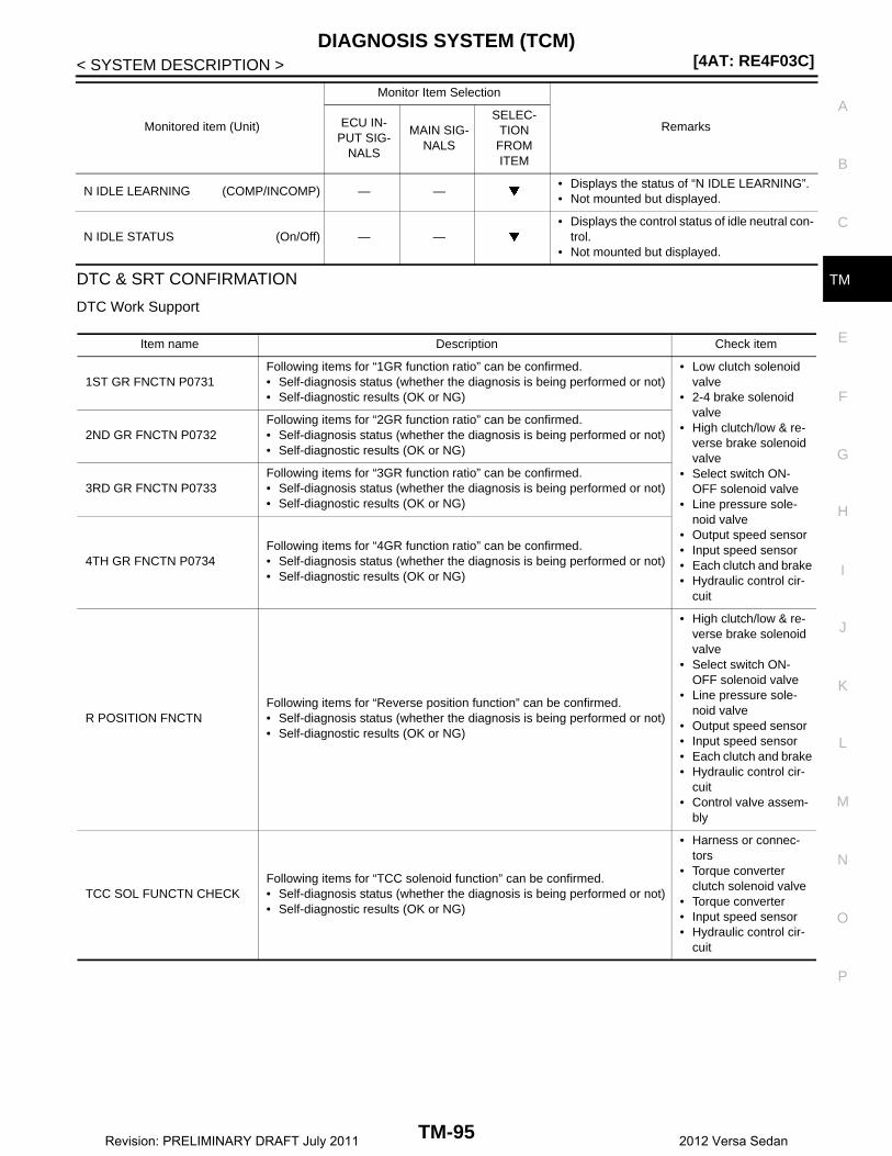
DIAGNOSIS SYSTEM (TCM)[4AT: RE4F03C]
C
E
F
G
H
I
J
K
L
M
A
B
M
N
O
P
< SYSTEM DESCRIPTION >
TDTC & SRT CONFIRMATION
DTC Work Support
N IDLE LEARNING (COMP/INCOMP) — —• Displays the status of “N IDLE LEARNING”.• Not mounted but displayed.
N IDLE STATUS (On/Off) — —• Displays the control status of idle neutral con-
trol.• Not mounted but displayed.
Monitored item (Unit)
Monitor Item Selection
RemarksECU IN-PUT SIG-
NALS
MAIN SIG-NALS
SELEC-TION
FROM ITEM
Item name Description Check item
1ST GR FNCTN P0731Following items for “1GR function ratio” can be confirmed.• Self-diagnosis status (whether the diagnosis is being performed or not)• Self-diagnostic results (OK or NG)
• Low clutch solenoid valve
• 2-4 brake solenoid valve
• High clutch/low & re-verse brake solenoid valve
• Select switch ON-OFF solenoid valve
• Line pressure sole-noid valve
• Output speed sensor• Input speed sensor• Each clutch and brake• Hydraulic control cir-
cuit
2ND GR FNCTN P0732Following items for “2GR function ratio” can be confirmed.• Self-diagnosis status (whether the diagnosis is being performed or not)• Self-diagnostic results (OK or NG)
3RD GR FNCTN P0733Following items for “3GR function ratio” can be confirmed.• Self-diagnosis status (whether the diagnosis is being performed or not)• Self-diagnostic results (OK or NG)
4TH GR FNCTN P0734Following items for “4GR function ratio” can be confirmed.• Self-diagnosis status (whether the diagnosis is being performed or not)• Self-diagnostic results (OK or NG)
R POSITION FNCTNFollowing items for “Reverse position function” can be confirmed.• Self-diagnosis status (whether the diagnosis is being performed or not)• Self-diagnostic results (OK or NG)
• High clutch/low & re-verse brake solenoid valve
• Select switch ON-OFF solenoid valve
• Line pressure sole-noid valve
• Output speed sensor• Input speed sensor• Each clutch and brake• Hydraulic control cir-
cuit• Control valve assem-
bly
TCC SOL FUNCTN CHECKFollowing items for “TCC solenoid function” can be confirmed.• Self-diagnosis status (whether the diagnosis is being performed or not)• Self-diagnostic results (OK or NG)
• Harness or connec-tors
• Torque converter clutch solenoid valve
• Torque converter• Input speed sensor• Hydraulic control cir-
cuit
TM-95Revision: PRELIMINARY DRAFT July 2011 2012 Versa Sedan

[4AT: RE4F03C]TCM
< ECU DIAGNOSIS INFORMATION >
ECU DIAGNOSIS INFORMATIONTCM
Reference Value INFOID:0000000007240819
VALUES ON DIAGNOSIS TOOLNOTE:1. The CONSULT electrically displays shift timing and lock-up timing (that is, operation timing of each sole-
noid).Check for time difference between actual shift timing and the CONSULT display. If the difference is notice-able, mechanical parts (except solenoids, sensors, etc.) may be malfunctioning. Check mechanical partsin accordance with the specified diagnostic procedures.
2. Shift schedule (that implies gear position) on CONSULT may slightly differ from that described in ServiceManual. This occurs for the following reasons:
- Actual shift schedule has more or less tolerance or allowance- Shift schedule in Service Manual refers to the point where shifting starts- Gear position on CONSULT indicates the point where shifting completes3. Display of solenoid valves on CONSULT changes at the start of shifting, while gear position is displayed
upon completion of shifting (which is computed by TCM).
CONSULT MONITOR ITEM
Item name Condition Value / Status (Approx.)
VHCL/S SE-A/T During drivingApproximately equals the speed-ometer reading.
ESTM VSP SIG During drivingApproximately equals the speed-ometer reading.
THROTTLE POSIAccelerator pedal is released 0.0/8
Accelerator pedal is fully depressed 8.0/8
ACCELE POSIAccelerator pedal is released 0.0/8
Accelerator pedal is fully depressed 8.0/8
CLSD THL POSAccelerator pedal is released On
Accelerator pedal is fully depressed Off
W/O THL POSAccelerator pedal is fully depressed On
Accelerator pedal is released Off
BRAKESWBrake pedal is depressed On
Brake pedal is released Off
ENGINE SPEED Engine runningClosely equals the tachometer reading.
INPUT SPEED During driving (lock-up ON)Approximately equals the engine speed.
OUTPUT REV During driving (lock-up ON) Tachometer / Gear ratio
TC SLIP SPEED During driving Engine speed − Input speed
FLUID TEMP Ignition switch is ONTemperature of ATF in the transax-le is indicated.
BATTERY VOLT Ignition switch is ON Battery voltage (11 V – 14 V)
RANGE SW 1Selector lever in “1” position On
Other than the above Off
RANGE SW 2Selector lever in “2” position On
Other than the above Off
RANGE SW DSelector lever in “D” position On
Other than the above Off
TM-96Revision: PRELIMINARY DRAFT July 2011 2012 Versa Sedan

TCM[4AT: RE4F03C]
C
E
F
G
H
I
J
K
L
M
A
B
M
N
O
P
< ECU DIAGNOSIS INFORMATION >
T
RANGE SW RSelector lever in “R” position On
Other than the above Off
RANGE SW PSelector lever in “P” position On
Other than the above Off
OD CONT SWWhen overdrive control switch is depressed On
When overdrive control switch is released Off
POWERSHIFT SW Always Off
ABS SIGNALABS operates On
Other than the above Off
GEAR During driving 1st, 2nd, 3rd, 4th
TC SLIP SPEED Slip lock-up is active 90 rpm
GEAR RATIO
Driving with 1GR 2.861
Driving with 2GR 1.562
Driving with 3GR 1.000
Driving with 4GR 0.697
LINE PRES SOL During driving 0 – 0.8 A
TCC SOLENOID
Slip lock-up is active 0.2 – 0.4 A
Lock-up is active 0.8 A
Other than the above 0 A
L/C SOLENOIDLow clutch is disengaged 1.0 A
Low clutch is engaged 0 A
H/C SOLENOIDHigh clutch is disengaged 1.0 A
High clutch is engaged 0 A
24/B SOLENOID2-4 brake is engaged 1.0 A
2-4 brake is disengaged 0 A
LR/B SOLENOIDLow&reverse brake is engaged 0 A
Low&reverse brake is disengaged 1.0 A
THL REVERSAL SINAccelerator pedal is released 8.0/8
Accelerator pedal is fully depressed 0.0/8
ATF TEMP SEN 0°C (32°F) – 20°C (68°F) – 80°C (176°F) 3.3 –2.7 – 0.9 V
L/P SOL MON During driving 0 – 0.8 A
TCC SOL MON
Slip lock-up is active 0.2 – 0.4 A
Lock-up is active 1.0 A
Other than the above 0 A
L/C SOL MONLow clutch is disengaged 1.0 A
Low clutch is engaged 0 A
H/C SOL MONHigh clutch is disengaged 1.0 A
High clutch is engaged 0 A
24/B SOL MON2-4 brake is engaged 1.0 A
2-4 brake is disengaged 0 A
LR/B SOL MONLow&reverse brake is engaged 0 A
Low&reverse brake is disengaged 1.0 A
ENGINE TORQUE During drivingChanges the value according to the acceleration or deceleration.
Item name Condition Value / Status (Approx.)
TM-97Revision: PRELIMINARY DRAFT July 2011 2012 Versa Sedan

[4AT: RE4F03C]TCM
< ECU DIAGNOSIS INFORMATION >
ENG TORQUE D During drivingChanges the value according to the acceleration or deceleration.
INPUT TRQ S During drivingChanges the value according to the acceleration or deceleration.
INPUT TRQ L/P During drivingChanges the value according to the acceleration or deceleration.
TRGT PRES L/P
Selector lever in “P”, “R” and “N” positions 646 – 2,000 kPa
Selector lever in “D” position 420 – 1,300 kPa
Other than the above 0 kPa
TRGT PRES TCC
Slip lock-up is active 0 – 250 kPa
Lock-up is active 1,279 kPa
Other than the above −500 kPa
TRGT PRES L/CLow clutch is engaged 1,300 kPa
Low clutch is disengaged 0 kPa
TRGT PRES H/CHigh clutch is disengaged 1,300 kPa
High clutch is engaged 0 kPa
TRGT PRES 24/B2-4 brake is engaged 1,300 kPa
2-4 brake is disengaged 0 kPa
TRGT PRES LR/B
Low&reverse brake is engaged (“D” position) 1,300 kPa
Low&reverse brake is engaged (“R” position) 2,000 kPa
Low&reverse brake is disengaged 0 kPa
SHIFT PATTERN During normal driving (without shift changes) 0xFF
VEHICLE SPEED During drivingApproximately equals the speed-ometer reading.
DRV CST JUDGEAccelerator pedal is depressed DRIVE
Accelerator pedal is released COAST
SHIFT IND SIGNAL
When the selector lever is positioned in between each po-sition.
Off
Selector lever in “P” position P
Selector lever in “R” position R
Selector lever in “N” position N
Selector lever in “D” position D
Selector lever in “D” position: 3GR 3
Selector lever in “D” and “2” positions: 2GR 2
Selector lever in “D” and “1” positions: 1GR 1
F-SAFE IND/LFor 2 seconds after the ignition switch is turned ON On
Other than the above Off
ATF WARN LAMPWhen TCM transmits the ATF indicator lamp signal On
Other than the above Off
ON/OFF SOLSelector lever in “P” and “N” positions On
Other than the above Off
ON OFF SOL MONSelector lever in “P”, “N”, “D1” and “1” positions On
Other than the above Off
NEXT GR POSI During driving 1st, 2nd, 3rd, 4th
Item name Condition Value / Status (Approx.)
TM-98Revision: PRELIMINARY DRAFT July 2011 2012 Versa Sedan

TCM[4AT: RE4F03C]
C
E
F
G
H
I
J
K
L
M
A
B
M
N
O
P
< ECU DIAGNOSIS INFORMATION >
T
TERMINAL LAYOUT
INPUT/OUTPUT SIGNAL STANDARD
SHIFT MODE
• Engine warming up• TSC, VDC operations
1
• Engine cold• TSC, VDC operations
2
ATF temperature: approx. 130 °C (266 °F) 3
Other than the above 0
LOCK-UP PATTERN Lock-up is active 2
Other than the above 0
THROTTLE FAILWhen TCM receives unusual engine torque signal On
Other than the above Off
Item name Condition Value / Status (Approx.)
JSDIA1968ZZ
Terminal No.(Wire color)
Conditions
Operation or operation conditions Standard
+ − SignalInput/Output
1(L/R)
GroundSelect switch ON-OFF solenoid valve
OutputIgnition switch ON
Selector lever: “P”, “N” “D1” and “1” positions
10 – 16 V
Other than the above Approx. 0 V
2(W)
Ground 1 position switch Input
Ignition switch ON
Selector lever: “1” position 10 – 16 V
Other than the above Approx. 0 V
3(R/B)
Ground 2 position switch InputSelector lever: “2” position 10 – 16 V
Other than the above Approx. 0 V
4(W/B)
Ground D position switch InputSelector lever: “D” position 10 – 16 V
Other than the above Approx. 0 V
5(L/B)
Ground N position switch InputSelector lever: “N” position 10 – 16 V
Other than the above Approx. 0 V
6(O)
Ground R position switch InputSelector lever: “R” position 10 – 16 V
Other than the above Approx. 0 V
7(Y)
Ground P position switch InputIgnition switch ON
Selector lever: “P” position 10 – 16 V
Other than the above Approx. 0 V
11(B)
Ground Sensor ground Input Always Approx. 0 V
TM-99Revision: PRELIMINARY DRAFT July 2011 2012 Versa Sedan
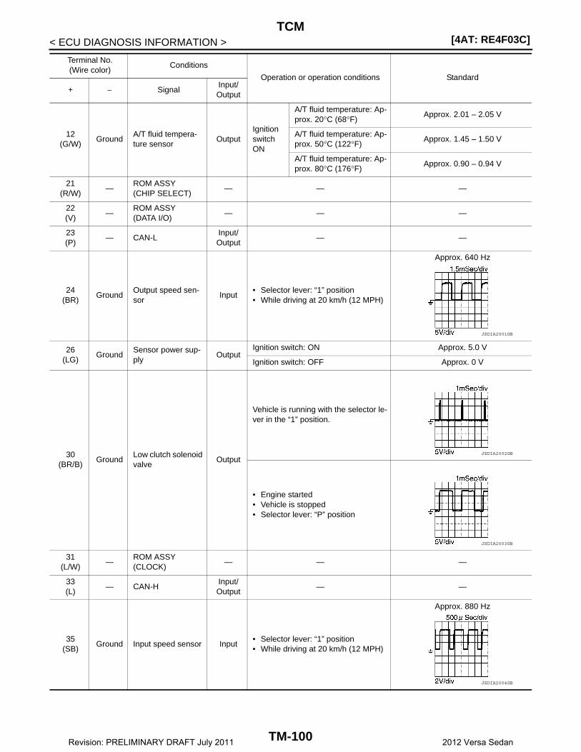
[4AT: RE4F03C]TCM
< ECU DIAGNOSIS INFORMATION >
12(G/W)
GroundA/T fluid tempera-ture sensor
OutputIgnition switch ON
A/T fluid temperature: Ap-prox. 20°C (68°F)
Approx. 2.01 – 2.05 V
A/T fluid temperature: Ap-prox. 50°C (122°F)
Approx. 1.45 – 1.50 V
A/T fluid temperature: Ap-prox. 80°C (176°F)
Approx. 0.90 – 0.94 V
21(R/W)
—ROM ASSY(CHIP SELECT)
— — —
22(V)
—ROM ASSY(DATA I/O)
— — —
23(P)
— CAN-LInput/Output
— —
24(BR)
GroundOutput speed sen-sor
Input• Selector lever: “1” position• While driving at 20 km/h (12 MPH)
Approx. 640 Hz
26(LG)
GroundSensor power sup-ply
OutputIgnition switch: ON Approx. 5.0 V
Ignition switch: OFF Approx. 0 V
30(BR/B)
GroundLow clutch solenoid valve
Output
Vehicle is running with the selector le-ver in the “1” position.
• Engine started• Vehicle is stopped• Selector lever: “P” position
31(L/W)
—ROM ASSY(CLOCK)
— — —
33(L)
— CAN-HInput/Output
— —
35(SB)
Ground Input speed sensor Input• Selector lever: “1” position• While driving at 20 km/h (12 MPH)
Approx. 880 Hz
Terminal No.(Wire color)
Conditions
Operation or operation conditions Standard
+ − SignalInput/Output
JSDIA2001GB
JSDIA2002GB
JSDIA2003GB
JSDIA2004GB
TM-100Revision: PRELIMINARY DRAFT July 2011 2012 Versa Sedan

TCM[4AT: RE4F03C]
C
E
F
G
H
I
J
K
L
M
A
B
M
N
O
P
< ECU DIAGNOSIS INFORMATION >
T
37(BR/W)
GroundLine pressure sole-noid valve
Output• Selector lever: “1” position• While driving at 20 km/h (12 MPH)
38(G)
GroundLock-up solenoid valve
Output
1. Selector lever: “D” position2. accelerate to more than 60 km/h
(37 MPH) 3. Throttle position:0.0/84. Check the pulse in 60 km/h (37
MPH)
• Engine started• Vehicle is stopped• Selector lever: “P” position
39(G/B)
Ground2-4 brake solenoid valve
Output
1. Selector lever: “D” position2. accelerate to more than 20 km/h
(12 MPH) 3. Throttle position:0.0/84. Check the pulse in 20 km/h (12
MPH)
• Engine started• Vehicle is stopped• Selector lever: “P” position
Terminal No.(Wire color)
Conditions
Operation or operation conditions Standard
+ − SignalInput/Output
JSDIA2005GB
JSDIA2006GB
JSDIA2007GB
JSDIA2008GB
JSDIA2009GB
TM-101Revision: PRELIMINARY DRAFT July 2011 2012 Versa Sedan
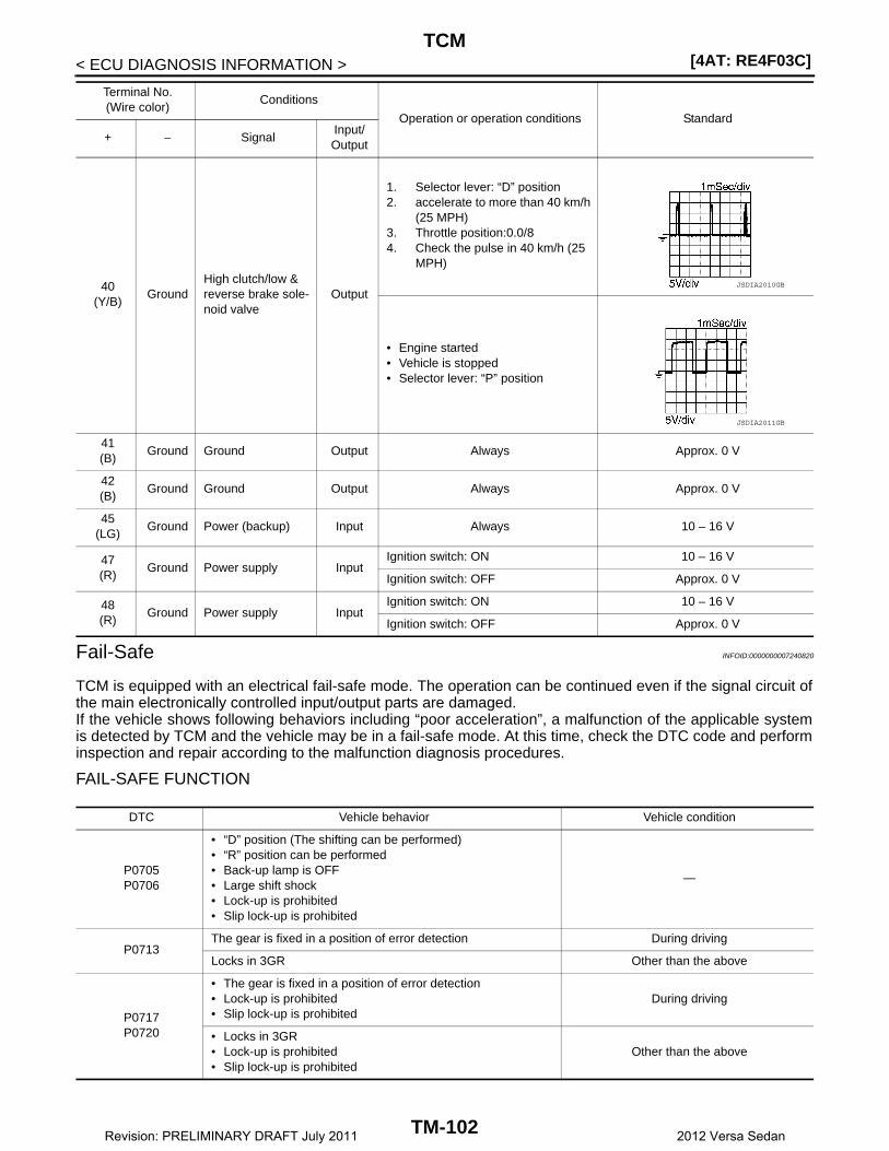
[4AT: RE4F03C]TCM
< ECU DIAGNOSIS INFORMATION >
Fail-Safe INFOID:0000000007240820
TCM is equipped with an electrical fail-safe mode. The operation can be continued even if the signal circuit ofthe main electronically controlled input/output parts are damaged.If the vehicle shows following behaviors including “poor acceleration”, a malfunction of the applicable systemis detected by TCM and the vehicle may be in a fail-safe mode. At this time, check the DTC code and performinspection and repair according to the malfunction diagnosis procedures.
FAIL-SAFE FUNCTION
40(Y/B)
GroundHigh clutch/low & reverse brake sole-noid valve
Output
1. Selector lever: “D” position2. accelerate to more than 40 km/h
(25 MPH) 3. Throttle position:0.0/84. Check the pulse in 40 km/h (25
MPH)
• Engine started• Vehicle is stopped• Selector lever: “P” position
41(B)
Ground Ground Output Always Approx. 0 V
42(B)
Ground Ground Output Always Approx. 0 V
45(LG)
Ground Power (backup) Input Always 10 – 16 V
47(R)
Ground Power supply InputIgnition switch: ON 10 – 16 V
Ignition switch: OFF Approx. 0 V
48(R)
Ground Power supply InputIgnition switch: ON 10 – 16 V
Ignition switch: OFF Approx. 0 V
Terminal No.(Wire color)
Conditions
Operation or operation conditions Standard
+ − SignalInput/Output
JSDIA2010GB
JSDIA2011GB
DTC Vehicle behavior Vehicle condition
P0705P0706
• “D” position (The shifting can be performed)• “R” position can be performed• Back-up lamp is OFF• Large shift shock• Lock-up is prohibited• Slip lock-up is prohibited
—
P0713The gear is fixed in a position of error detection During driving
Locks in 3GR Other than the above
P0717P0720
• The gear is fixed in a position of error detection• Lock-up is prohibited• Slip lock-up is prohibited
During driving
• Locks in 3GR• Lock-up is prohibited• Slip lock-up is prohibited
Other than the above
TM-102Revision: PRELIMINARY DRAFT July 2011 2012 Versa Sedan

TCM[4AT: RE4F03C]
C
E
F
G
H
I
J
K
L
M
A
B
M
N
O
P
< ECU DIAGNOSIS INFORMATION >
T
P0731• Locks in 2GR or 3GR• Lock-up is prohibited
—
P0732• Locks in 3GR• Lock-up is prohibited
—
P0733P0734
• The gear is fixed in neutral until vehicle speed decreases to below 5 km/h (3 MPH) and in 2GR when reaching 5 km/h (3 MPH) or more
• Lock-up is prohibited
—
P0740P0743P0744
Lock-up is prohibited —
P0973P0974
• The gear is fixed in neutral until vehicle speed decreases to below 5 km/h (3 MPH) and in 2GR when reaching 5 km/h (3 MPH) or more
• Lock-up is prohibited
—
P1735 Locks in 2GR —
P1736 Locks in 3GR —
P1737P1738
The gear is fixed in neutral until vehicle speed decreases to be-low 5 km/h (3 MPH) and in 2GR when reaching 5 km/h (3 MPH) or more
—
P1744 Slip lock-up is prohibited —
P17A1P17A2P17A3
• Locks in 4GR• Lock-up is prohibited
—
P17A4
• The gear is fixed in neutral until vehicle speed decreases to below 5 km/h (3 MPH) and in 2GR or 3GR when reaching 5 km/h (3 MPH) or more
• Lock-up is prohibited
—
P17AAP17AB
• Locks in 3GR• Lock-up is prohibited
—
P17ADP17AE
• The gear is fixed in neutral until vehicle speed decreases to below 5 km/h (3 MPH) and in 3GR when reaching 5 km/h (3 MPH) or more
• Lock-up is prohibited
—
P17B0P17B1
• Locks in 3GR• Lock-up is prohibited
—
U0073
• The gear is fixed in 3GR until vehicle speed decreases to be-low 5 km/h (3 MPH) and in 2GR when reaching 5 km/h (3 MPH) or more
• Lock-up is prohibited• Slip lock-up is prohibited
—
U0100
• Locks in 3GR• Lock-up is prohibited• Slip lock-up is prohibited
During driving
• Locks in 2GR• Lock-up is prohibited• Slip lock-up is prohibited
Other than the above
U0155 O/D OFF prohibited —
U0300
• Locks in 3GR• Lock-up is prohibited• Slip lock-up is prohibited
During driving
• Locks in 2GR• Lock-up is prohibited• Slip lock-up is prohibited
Other than the above
DTC Vehicle behavior Vehicle condition
TM-103Revision: PRELIMINARY DRAFT July 2011 2012 Versa Sedan
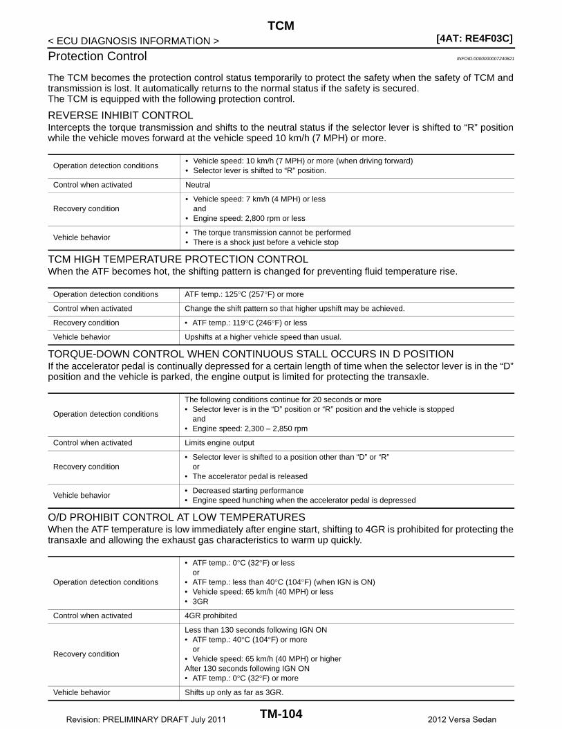
[4AT: RE4F03C]TCM
< ECU DIAGNOSIS INFORMATION >
Protection Control INFOID:0000000007240821
The TCM becomes the protection control status temporarily to protect the safety when the safety of TCM andtransmission is lost. It automatically returns to the normal status if the safety is secured.The TCM is equipped with the following protection control.
REVERSE INHIBIT CONTROLIntercepts the torque transmission and shifts to the neutral status if the selector lever is shifted to “R” positionwhile the vehicle moves forward at the vehicle speed 10 km/h (7 MPH) or more.
TCM HIGH TEMPERATURE PROTECTION CONTROLWhen the ATF becomes hot, the shifting pattern is changed for preventing fluid temperature rise.
TORQUE-DOWN CONTROL WHEN CONTINUOUS STALL OCCURS IN D POSITIONIf the accelerator pedal is continually depressed for a certain length of time when the selector lever is in the “D”position and the vehicle is parked, the engine output is limited for protecting the transaxle.
O/D PROHIBIT CONTROL AT LOW TEMPERATURESWhen the ATF temperature is low immediately after engine start, shifting to 4GR is prohibited for protecting thetransaxle and allowing the exhaust gas characteristics to warm up quickly.
Operation detection conditions• Vehicle speed: 10 km/h (7 MPH) or more (when driving forward)• Selector lever is shifted to “R” position.
Control when activated Neutral
Recovery condition• Vehicle speed: 7 km/h (4 MPH) or less
and• Engine speed: 2,800 rpm or less
Vehicle behavior• The torque transmission cannot be performed• There is a shock just before a vehicle stop
Operation detection conditions ATF temp.: 125°C (257°F) or more
Control when activated Change the shift pattern so that higher upshift may be achieved.
Recovery condition • ATF temp.: 119°C (246°F) or less
Vehicle behavior Upshifts at a higher vehicle speed than usual.
Operation detection conditions
The following conditions continue for 20 seconds or more• Selector lever is in the “D” position or “R” position and the vehicle is stopped
and• Engine speed: 2,300 – 2,850 rpm
Control when activated Limits engine output
Recovery condition• Selector lever is shifted to a position other than “D” or “R”
or• The accelerator pedal is released
Vehicle behavior• Decreased starting performance• Engine speed hunching when the accelerator pedal is depressed
Operation detection conditions
• ATF temp.: 0°C (32°F) or lessor
• ATF temp.: less than 40°C (104°F) (when IGN is ON)• Vehicle speed: 65 km/h (40 MPH) or less• 3GR
Control when activated 4GR prohibited
Recovery condition
Less than 130 seconds following IGN ON• ATF temp.: 40°C (104°F) or more
or• Vehicle speed: 65 km/h (40 MPH) or higherAfter 130 seconds following IGN ON• ATF temp.: 0°C (32°F) or more
Vehicle behavior Shifts up only as far as 3GR.
TM-104Revision: PRELIMINARY DRAFT July 2011 2012 Versa Sedan
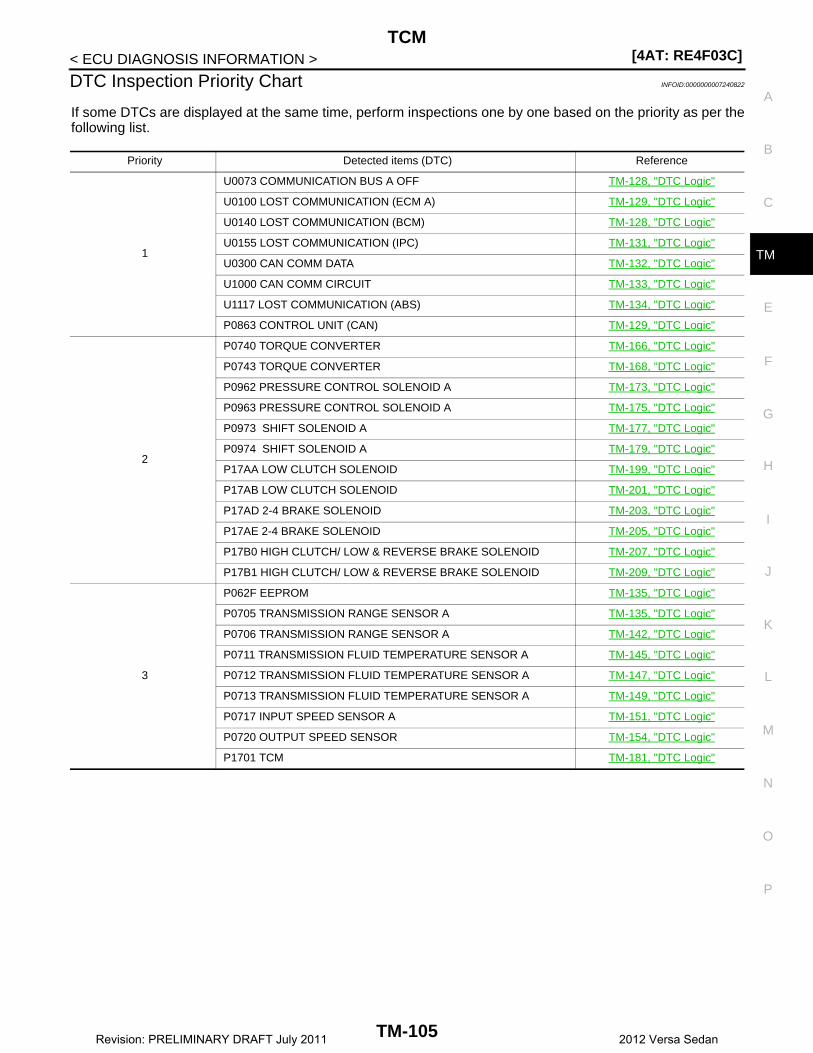
TCM[4AT: RE4F03C]
C
E
F
G
H
I
J
K
L
M
A
B
M
N
O
P
< ECU DIAGNOSIS INFORMATION >
T
DTC Inspection Priority Chart INFOID:0000000007240822
If some DTCs are displayed at the same time, perform inspections one by one based on the priority as per thefollowing list.
Priority Detected items (DTC) Reference
1
U0073 COMMUNICATION BUS A OFF TM-128, "DTC Logic"
U0100 LOST COMMUNICATION (ECM A) TM-129, "DTC Logic"
U0140 LOST COMMUNICATION (BCM) TM-128, "DTC Logic"
U0155 LOST COMMUNICATION (IPC) TM-131, "DTC Logic"
U0300 CAN COMM DATA TM-132, "DTC Logic"
U1000 CAN COMM CIRCUIT TM-133, "DTC Logic"
U1117 LOST COMMUNICATION (ABS) TM-134, "DTC Logic"
P0863 CONTROL UNIT (CAN) TM-129, "DTC Logic"
2
P0740 TORQUE CONVERTER TM-166, "DTC Logic"
P0743 TORQUE CONVERTER TM-168, "DTC Logic"
P0962 PRESSURE CONTROL SOLENOID A TM-173, "DTC Logic"
P0963 PRESSURE CONTROL SOLENOID A TM-175, "DTC Logic"
P0973 SHIFT SOLENOID A TM-177, "DTC Logic"
P0974 SHIFT SOLENOID A TM-179, "DTC Logic"
P17AA LOW CLUTCH SOLENOID TM-199, "DTC Logic"
P17AB LOW CLUTCH SOLENOID TM-201, "DTC Logic"
P17AD 2-4 BRAKE SOLENOID TM-203, "DTC Logic"
P17AE 2-4 BRAKE SOLENOID TM-205, "DTC Logic"
P17B0 HIGH CLUTCH/ LOW & REVERSE BRAKE SOLENOID TM-207, "DTC Logic"
P17B1 HIGH CLUTCH/ LOW & REVERSE BRAKE SOLENOID TM-209, "DTC Logic"
3
P062F EEPROM TM-135, "DTC Logic"
P0705 TRANSMISSION RANGE SENSOR A TM-135, "DTC Logic"
P0706 TRANSMISSION RANGE SENSOR A TM-142, "DTC Logic"
P0711 TRANSMISSION FLUID TEMPERATURE SENSOR A TM-145, "DTC Logic"
P0712 TRANSMISSION FLUID TEMPERATURE SENSOR A TM-147, "DTC Logic"
P0713 TRANSMISSION FLUID TEMPERATURE SENSOR A TM-149, "DTC Logic"
P0717 INPUT SPEED SENSOR A TM-151, "DTC Logic"
P0720 OUTPUT SPEED SENSOR TM-154, "DTC Logic"
P1701 TCM TM-181, "DTC Logic"
TM-105Revision: PRELIMINARY DRAFT July 2011 2012 Versa Sedan
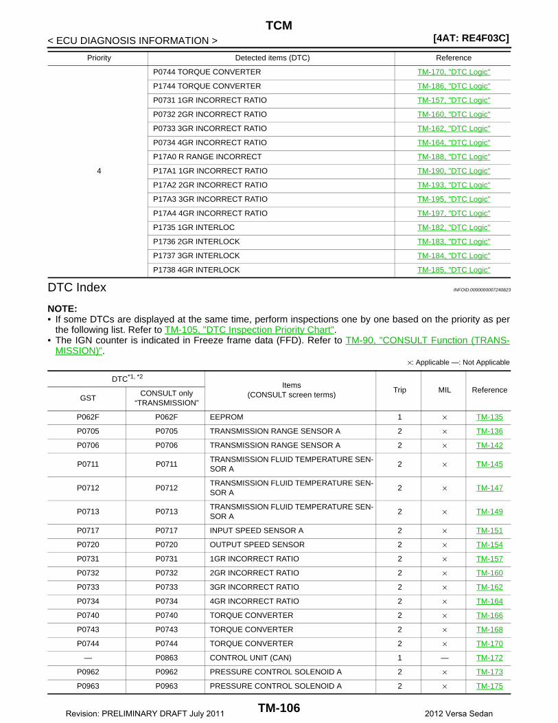
[4AT: RE4F03C]TCM
< ECU DIAGNOSIS INFORMATION >
DTC Index INFOID:0000000007240823
NOTE:• If some DTCs are displayed at the same time, perform inspections one by one based on the priority as per
the following list. Refer to TM-105, "DTC Inspection Priority Chart".• The IGN counter is indicated in Freeze frame data (FFD). Refer to TM-90, "CONSULT Function (TRANS-
MISSION)".×: Applicable —: Not Applicable
4
P0744 TORQUE CONVERTER TM-170, "DTC Logic"
P1744 TORQUE CONVERTER TM-186, "DTC Logic"
P0731 1GR INCORRECT RATIO TM-157, "DTC Logic"
P0732 2GR INCORRECT RATIO TM-160, "DTC Logic"
P0733 3GR INCORRECT RATIO TM-162, "DTC Logic"
P0734 4GR INCORRECT RATIO TM-164, "DTC Logic"
P17A0 R RANGE INCORRECT TM-188, "DTC Logic"
P17A1 1GR INCORRECT RATIO TM-190, "DTC Logic"
P17A2 2GR INCORRECT RATIO TM-193, "DTC Logic"
P17A3 3GR INCORRECT RATIO TM-195, "DTC Logic"
P17A4 4GR INCORRECT RATIO TM-197, "DTC Logic"
P1735 1GR INTERLOC TM-182, "DTC Logic"
P1736 2GR INTERLOCK TM-183, "DTC Logic"
P1737 3GR INTERLOCK TM-184, "DTC Logic"
P1738 4GR INTERLOCK TM-185, "DTC Logic"
Priority Detected items (DTC) Reference
DTC*1, *2
Items(CONSULT screen terms)
Trip MIL ReferenceGST
CONSULT only “TRANSMISSION”
P062F P062F EEPROM 1 × TM-135
P0705 P0705 TRANSMISSION RANGE SENSOR A 2 × TM-136
P0706 P0706 TRANSMISSION RANGE SENSOR A 2 × TM-142
P0711 P0711TRANSMISSION FLUID TEMPERATURE SEN-SOR A
2 × TM-145
P0712 P0712TRANSMISSION FLUID TEMPERATURE SEN-SOR A
2 × TM-147
P0713 P0713TRANSMISSION FLUID TEMPERATURE SEN-SOR A
2 × TM-149
P0717 P0717 INPUT SPEED SENSOR A 2 × TM-151
P0720 P0720 OUTPUT SPEED SENSOR 2 × TM-154
P0731 P0731 1GR INCORRECT RATIO 2 × TM-157
P0732 P0732 2GR INCORRECT RATIO 2 × TM-160
P0733 P0733 3GR INCORRECT RATIO 2 × TM-162
P0734 P0734 4GR INCORRECT RATIO 2 × TM-164
P0740 P0740 TORQUE CONVERTER 2 × TM-166
P0743 P0743 TORQUE CONVERTER 2 × TM-168
P0744 P0744 TORQUE CONVERTER 2 × TM-170
— P0863 CONTROL UNIT (CAN) 1 — TM-172
P0962 P0962 PRESSURE CONTROL SOLENOID A 2 × TM-173
P0963 P0963 PRESSURE CONTROL SOLENOID A 2 × TM-175
TM-106Revision: PRELIMINARY DRAFT July 2011 2012 Versa Sedan

TCM[4AT: RE4F03C]
C
E
F
G
H
I
J
K
L
M
A
B
M
N
O
P
< ECU DIAGNOSIS INFORMATION >
T
*1: These numbers are prescribed by SAE J2012/ISO 15031-6.
*2: The items are the same as those of 1st trip freeze frame data.
P0973 P0973 SHIFT SOLENOID A 2 × TM-177
P0974 P0974 SHIFT SOLENOID A 2 × TM-179
P1701 P1701 TCM 1 × TM-181
P1735 P1735 1GR INTERLOC 2 × TM-182
P1736 P1736 2GR INTERLOCK 2 × TM-183
P1737 P1737 3GR INTERLOCK 2 × TM-184
P1738 P1738 4GR INTERLOCK 2 × TM-185
P1744 P1744 TORQUE CONVERTER 2 × TM-186
— P17A0 R RANGE INCORRECT 2 — TM-188
P17A1 P17A1 1GR INCORRECT RATIO 2 × TM-190
P17A2 P17A2 2GR INCORRECT RATIO 2 × TM-193
P17A3 P17A3 3GR INCORRECT RATIO 2 × TM-195
P17A4 P17A4 4GR INCORRECT RATIO 2 × TM-197
P17AA P17AA LOW CLUTCH SOLENOID 2 × TM-199
P17AB P17AB LOW CLUTCH SOLENOID 2 × TM-201
P17AD P17AD 2-4 BRAKE SOLENOID 2 × TM-203
P17AE P17AE 2-4 BRAKE SOLENOID 2 × TM-205
P17B0 P17B0HIGH CLUTCH/LOW & REVERSE BRAKE SO-LENOID
2 × TM-207
P17B1 P17B1HIGH CLUTCH/LOW & REVERSE BRAKE SO-LENOID
2 × TM-209
U0073 U0073 COMMUNICATION BUS A OFF 1 × TM-128
U0100 U0100 LOST COMMUNICATION (ECM A) 2 × TM-129
— U0140 LOST COMMUNICATION (BCM) 1 — TM-130
— U0155 LOST COMMUNICATION (IPC) 1 — TM-131
U0300 U0300 CAN COMM DATA 1 × TM-132
— U1000 CAN COMM CIRCUIT 1 — TM-133
— U1117 LOST COMMUNICATION (ABS) 1 — TM-134
DTC*1, *2
Items(CONSULT screen terms)
Trip MIL ReferenceGST
CONSULT only “TRANSMISSION”
TM-107Revision: PRELIMINARY DRAFT July 2011 2012 Versa Sedan
[4AT: RE4F03C]A/T CONTROL SYSTEM
< WIRING DIAGRAM >
WIRING DIAGRAMA/T CONTROL SYSTEM
Wiring Diagram INFOID:0000000007240824
ABDWA0522GB
TM-108Revision: PRELIMINARY DRAFT July 2011 2012 Versa Sedan

A/T CONTROL SYSTEM[4AT: RE4F03C]
C
E
F
G
H
I
J
K
L
M
A
B
M
N
O
P
< WIRING DIAGRAM >
T
AADWA0179GB
TM-109Revision: PRELIMINARY DRAFT July 2011 2012 Versa Sedan

[4AT: RE4F03C]A/T CONTROL SYSTEM
< WIRING DIAGRAM >
ABDIA0761GB
TM-110Revision: PRELIMINARY DRAFT July 2011 2012 Versa Sedan

A/T CONTROL SYSTEM[4AT: RE4F03C]
C
E
F
G
H
I
J
K
L
M
A
B
M
N
O
P
< WIRING DIAGRAM >
T
ABDIA0762GB
TM-111Revision: PRELIMINARY DRAFT July 2011 2012 Versa Sedan

[4AT: RE4F03C]A/T CONTROL SYSTEM
< WIRING DIAGRAM >
ABDIA0763GB
TM-112Revision: PRELIMINARY DRAFT July 2011 2012 Versa Sedan

A/T CONTROL SYSTEM[4AT: RE4F03C]
C
E
F
G
H
I
J
K
L
M
A
B
M
N
O
P
< WIRING DIAGRAM >
T
ABDIA0764GB
TM-113Revision: PRELIMINARY DRAFT July 2011 2012 Versa Sedan
[4AT: RE4F03C]A/T SHIFT LOCK SYSTEM
< WIRING DIAGRAM >
A/T SHIFT LOCK SYSTEM
Wiring Diagram INFOID:0000000007240827
ABDWA0523GB
TM-114Revision: PRELIMINARY DRAFT July 2011 2012 Versa Sedan

A/T SHIFT LOCK SYSTEM[4AT: RE4F03C]
C
E
F
G
H
I
J
K
L
M
A
B
M
N
O
P
< WIRING DIAGRAM >
T
ABDIA0765GB
TM-115Revision: PRELIMINARY DRAFT July 2011 2012 Versa Sedan

[4AT: RE4F03C]DIAGNOSIS AND REPAIR WORK FLOW
< BASIC INSPECTION >
BASIC INSPECTIONDIAGNOSIS AND REPAIR WORK FLOW
Diagnosis Flow INFOID:0000000007240830
1.OBTAIN INFORMATION ABOUT SYMPTOM
Refer to TM-117, "Question sheet" and interview the customer to obtain the malfunction information (condi-tions and environment when the malfunction occurred) as much as possible when the customer brings in thevehicle.
>> GO TO 2.
2.CHECK DTC
1. Before checking the malfunction, check whether any DTC exists.2. If DTC exists, perform the following operations.- Record the DTC and freeze frame data. (Print out the data using CONSULT and affix them to the Work
Order Sheet.)- Erase DTCs.- Check the relationship between the cause that is clarified with DTC and the malfunction information
described by the customer. TM-219, "Symptom Table" is effective.3. Check the information of related service bulletins and others also.Do malfunction information and DTC exist?Malfunction information and DTC exists. >>GO TO 3.Malfunction information exists, but no DTC. >>GO TO 4.No malfunction information, but DTC exists. >>GO TO 5.
3.REPRODUCE MALFUNCTION SYMPTOM
Check any malfunction described by a customer, except those with DTC on the vehicle.Also investigate whether the symptom is a fail-safe or normal operation. Refer to TM-102, "Fail-Safe".When a malfunction symptom is reproduced, the question sheet is effective. Refer to TM-117, "Questionsheet".Verify the relationship between the symptom and the conditions in which the malfunction described by the cus-tomer occurs.
>> GO TO 5.
4.REPRODUCE MALFUNCTION SYMPTOM
Check the malfunction described by the customer on the vehicle.Also investigate whether the symptom is a fail-safe or normal operation. Refer to TM-102, "Fail-Safe".When a malfunction symptom is reproduced, the question sheet is effective. Refer to TM-117, "Questionsheet".Verify the relationship between the symptom and the conditions in which the malfunction described by the cus-tomer occurs.
>> GO TO 6.
5.PERFORM “DTC CONFIRMATION PROCEDURE”
Perform “DTC CONFIRMATION PROCEDURE” of the appropriate DTC to check if DTC is detected again.Refer to TM-105, "DTC Inspection Priority Chart" when multiple DTCs are detected, and then determine theorder for performing the diagnosis.NOTE:If no DTC is detected, refer to the freeze frame data.Is any DTC detected?YES >> GO TO 7.NO >> Check according to XX-XX, "*****".
6.IDENTIFY MALFUNCTIONING SYSTEM WITH “DIAGNOSIS CHART BY SYMPTOM”
TM-116Revision: PRELIMINARY DRAFT July 2011 2012 Versa Sedan

DIAGNOSIS AND REPAIR WORK FLOW[4AT: RE4F03C]
C
E
F
G
H
I
J
K
L
M
A
B
M
N
O
P
< BASIC INSPECTION >
T
Use TM-219, "Symptom Table" from the symptom inspection result in step 4. Then identify where to start per-forming the diagnosis based on possible causes and symptoms.
>> GO TO 8.
7.REPAIR OR REPLACE THE MALFUNCTIONING PARTS
Repair or replace the detected malfunctioning parts.Reconnect parts or connector after repairing or replacing, and then erase DTC if necessary.
>> GO TO 8.
8.FINAL CHECK
Perform “DTC CONFIRMATION PROCEDURE” again to make sure that the repair is correctly performed.Check that malfunctions are not reproduced when obtaining the malfunction information from the customer,referring to the symptom inspection result in step 3 or 4.Is DTC or malfunction symptom reproduced?YES-1 >> DTC is reproduced: GO TO 5.YES-2 >> Malfunction symptom is reproduced: GO TO 6.NO >> Before delivering the vehicle to the customer, make sure that DTC is erased.
Question sheet INFOID:0000000007240831
DESCRIPTIONThere are many operating conditions that may cause a malfunctionof the transmission parts. By understanding those conditions prop-erly, a quick and exact diagnosis can be achieved.In general, customers have their own criteria for a problem. There-fore, it is important to understand the symptom and status wellenough by asking the customer about the concerns carefully. Inorder to systemize all the information for the diagnosis, prepare thequestion sheet referring to the question points.
WORKSHEET SAMPLE
SEF907L
Question Sheet
Customer name MR/MS Engine # Manuf. Date
Incident Date VIN
Model & Year In Service Date
Trans. Mileage km/Mile
Symptoms Vehicle does not move ( Any position Particular position )
No upshift ( 1GR → 2GR 2GR → 3GR 3GR → 4GR)
No downshift ( 4GR → 3GR 3GR → 2GR 2GR → 1GR)
Lock-up malfunction
Shift point too high or too low
Shift shock or slip
Noise or vibration
No kick down
No pattern select
Others
Frequency All the time Under certain conditions Sometimes ( times a day)
TM-117Revision: PRELIMINARY DRAFT July 2011 2012 Versa Sedan

[4AT: RE4F03C]DIAGNOSIS AND REPAIR WORK FLOW
< BASIC INSPECTION >
Weather conditions Not affected
Weather Fine Cloud Rain Snow Other ( )
Temp. Hot Warm Cool Cold Temp. (Approx. °C/°F)
Humidity High Middle Low
Transmission conditions Not affected
Cold During warm-up After warm-up
Engine speed ( rpm)
Road conditions Not affected
In town In suburbs Freeway Off road (Up/Down)
Driving conditions Not affected
At starting While idling While engine racing At racing While cruis-
ing
While accelerating While decelerating While turning (Right/Left)
Vehicle speed [ km/h ( MPH)]
Other conditions
Question Sheet
TM-118Revision: PRELIMINARY DRAFT July 2011 2012 Versa Sedan

ADDITIONAL SERVICE WHEN REPLACING TCM[4AT: RE4F03C]
C
E
F
G
H
I
J
K
L
M
A
B
M
N
O
P
< BASIC INSPECTION >
T
ADDITIONAL SERVICE WHEN REPLACING TCM
Description INFOID:0000000007240832
Always perform the following items when the TCM is replaced.
LOADING OF THE CALIBRATION DATA• The TCM acquires calibration data (individual characteristic value) of each solenoid that is stored in the
ROM assembly (in the control valve). This enables the TCM to perform accurate control. After the TCM isreplaced, check that the TCM has correctly loaded the calibration data.
CAUTION:When replacing TCM and transaxle assembly as a set, replace transaxle assembly first and thenreplace TCM.If the TCM is replaced in advance, perform "TRANSAXLE ASSEMBLY REPLACEMENT: Special RepairRequirement".
Work Procedure INFOID:0000000007240833
1.CHECK WORK CONTENTS
Replacing only the TCM>>GO TO 2.Replacing the TCM after the transaxle assembly is replaced>>GO TO 2.Replacing the transaxle assembly after the TCM is replaced>>GO TO 4.
2.CHECK AFTER TCM IS REPLACED
1. Shift the selector lever to the P position.2. Turn ignition switch ON.3. Turn ignition switch OFF and wait for a minimum of 20 seconds.4. Turn ignition switch ON.5. Check that “P” is displayed on shift position indicator on combination meter.
NOTE:Displayed approximately 2 seconds after the selector lever is moved to the P position.
Does the shift position indicator display “P”?YES >> WORK ENDNO >> GO TO 3.
3.DETECT MALFUNCTION ITEMS
Check the following items:• Harness between the TCM and the ROM assembly inside the transaxle assembly is open or shorted.• Disconnected, loose, bent, collapsed, or otherwise abnormal connector housing terminalsIs the inspection result normal?YES >> GO TO 2.NO >> Repair or replace the malfunctioning parts.
4.PERFORM TRANSAXLE ASSEMBLY REPLACEMENT
Perform “TRANSAXLE ASSEMBLY REPLACEMENT: Special Repair Requirement”.
>> Refer to TM-120, "Work Procedure".
TM-119Revision: PRELIMINARY DRAFT July 2011 2012 Versa Sedan
[4AT: RE4F03C]ADDITIONAL SERVICE WHEN REPLACING TRANSAXLE ASSEMBLY
< BASIC INSPECTION >
ADDITIONAL SERVICE WHEN REPLACING TRANSAXLE ASSEMBLY
Description INFOID:0000000007240834
Perform the following work after the transaxle assembly is replaced.
ERASING AND LOADING OF THE CALIBRATION DATA• The TCM acquires calibration data (individual characteristic value) of each solenoid that is stored in the
ROM assembly (in the control valve). This enables the TCM to perform accurate control. For this reason,after the transaxle assembly is replaced, it is necessary to erase the calibration data that is stored in theTCM and load new calibration data.
ERASING THE LEARNED VALUE DATA• TCM learns indicated pressure for appropriate control of the transaxle assembly and records the learned
values. For this reason, the leaned values stored in TCM must be erased after replacing a transaxle assem-bly.
Work Procedure INFOID:0000000007240835
1.INITIALIZE TCM
With CONSULT1. Set parking brake.2. Turn ignition switch ON.3. Select “Work Support” in “TRANSMISSION”.4. Select “ERASE MEMORY DATA”.5. While maintaining the conditions below, touch “Start”.- Vehicle stop status- With engine stopped- Selector lever: “R” position- Accelerator pedal: DepressedNOTE:Select “Start” and complete within approximately 20 seconds.Is “COMPLETED” displayed?YES >> GO TO 2.NO >> Turn ignition switch OFF and wait for a minimum of 20 seconds then perform the work again.
2.CHECK AFTER TCM IS INITIALIZED
With CONSULT1. Turn ignition switch OFF with the selector lever in “R” position and wait for 20 seconds or more.2. Turn ignition switch ON with the selector lever in “R” position.
CAUTION:Never start the engine.
3. Select “CALIB DATA” in “TRANSMISSION”.4. Check that indicated value of “CALIB DATA” is equal to the value shown in the following table.
Is the indicated value of “CALIB DATA” equal to the value shown in the table?YES >> GO TO 3.NO >> GO TO 1.
3.CHECK LOADING OF CALIBRATION DATA
1. Shift the selector lever to the “P” position.2. Check that “P” is displayed on shift position indicator on combination meter.
NOTE:Displayed approximately 5 seconds after the selector lever is moved to the “P” position.
Does shift position indicator display “P”?
Item name Display value
C/V CLB ID 00
UNIT CLB ID 00
TM-120Revision: PRELIMINARY DRAFT July 2011 2012 Versa Sedan

ADDITIONAL SERVICE WHEN REPLACING TRANSAXLE ASSEMBLY[4AT: RE4F03C]
C
E
F
G
H
I
J
K
L
M
A
B
M
N
O
P
< BASIC INSPECTION >
T
YES >> WORK ENDNO >> GO TO 4.
4.DETECT MALFUNCTION ITEMS
Check the following items:• Harness between the TCM and the ROM assembly inside the transaxle assembly is open or shorted.• Disconnected, loose, bent, collapsed, or otherwise abnormal connector housing terminalsIs the inspection result normal?YES >> GO TO 1.NO >> Repair or replace the malfunctioning parts.
TM-121Revision: PRELIMINARY DRAFT July 2011 2012 Versa Sedan

[4AT: RE4F03C]A/T FLUID
< BASIC INSPECTION >
A/T FLUID
Changing INFOID:0000000007240836
CAUTION:• Use only Genuine NISSAN Matic S ATF. Never mix with other ATF.• Using ATF other than Genuine NISSAN Matic S ATF will cause deterioration driveability and A/T
durability, and may damagethe A/T, which is not covered by the warranty.• Always use shop paper. Never use shop cloth.• Replace a drain plug gasket with new ones at the final stage of the operation when installing.• Use caution when looking into the drain hole as there is a risk of dripping fluid entering the eye.• After replacement, always perform an ATF leakage check.1. Select “Data Monitor” in “TRANSMISSION” using CONSULT.2. Select “FLUID TEMP”, and check that the A/T fluid temperature is 40 °C (104°F) or less.3. Check that the selector lever is in the “P” position, then completely engage the parking brake.4. Lift up the vehicle.5. Remove the drain plug and overflow tube, and then drain the ATF from the oil pan. Refer to TM-235,
"Removal and Installation".6. Install the charging pipe set (KV311039S0) (A) into the drain
hole.CAUTION:Tighten the charging pipe by hand.
7. Install the ATF changer hose (B) to the charging pipe.CAUTION:Press the ATF changer hose all the way onto the chargingpipe until it stops.
8. Fill approximately 3 liters (2-5/8 lmp qt) of the ATF.9. Remove the ATF changer hose and charging pipe, then install
the drain plug.NOTE:Perform this work quickly because ATF leaks.
10. Lift down the vehicle.11. Start the engine.12. While depressing the brake pedal, shift the selector lever to the entire position from “P” to “1”, and shift it
to the “P” position.NOTE:Hold the lever at each position for 5 seconds.
13. Check that the CONSULT “Data Monitor” in “FLUID TEMP ” is 35 to 45°C (95 to 113°F).14. Stop the engine.15. Lift up the vehicle.16. Remove the drain plug, and then drain the ATF from the oil pan.17. Repeat steps 6 to 16 (one time).18. Install the overflow tube. Refer to TM-235, "Removal and Installation".
CAUTION:Be sure to tighten to the specified torque. If it is not tightened to the specified torque, the tube maybe damaged.
A/T fluid : Refer to XX-XX, "*****".Fluid capacity : Refer to XX-XX, "*****".
JSDIA1950ZZ
TM-122Revision: PRELIMINARY DRAFT July 2011 2012 Versa Sedan

A/T FLUID[4AT: RE4F03C]
C
E
F
G
H
I
J
K
L
M
A
B
M
N
O
P
< BASIC INSPECTION >
T
19. Install the charging pipe set (KV311039S0) (A) into the drainhole.CAUTION:Tighten the charging pipe by hand.
20. Install the ATF changer hose (B) to the charging pipe.CAUTION:Press the ATF changer hose all the way onto the chargingpipe until it stops.
21. Fill approximately 3 liters (2-5/8 lmp qt) of the ATF.22. Remove the ATF changer hose and charging pipe, then install
the drain plug.NOTE:Perform this work quickly because ATF leaks.
23. Lift down the vehicle.24. Start the engine.25. While depressing the brake pedal, shift the selector lever to the entire position from “P” to “1”, and shift it
to the “P” position.NOTE:Hold the lever at each position for 5 seconds.
26. Check that the CONSULT “Data Monitor” in “FLUID TEMP ” is 35 to 45°C (95 to 113°F).27. Lift up the vehicle.28. Remove the drain plug and check that ATF is drained out from the overflow tube.
CAUTION:Perform this work with the vehicle idling.NOTE:If the ATF is not drained out, refer to "Adjustment" and add ATF.
29. When the flow of ATF slows to a drip, tighten the drain plug to the specified torque. Refer to TM-235,"Removal and Installation".CAUTION:Never reuse drain plug gasket.
30. Lift down the vehicle.31. Stop the engine.
Adjustment INFOID:0000000007240837
CAUTION:• Use only Genuine NISSAN Matic S ATF. Never mix with other ATF.• Using ATF other than Genuine NISSAN Matic S ATF will cause deterioration driveability and A/T
durability, and may damagethe A/T, which is not covered by the warranty.• During adjusting of the ATF level, check CONSULT so that the fluid temperature may be maintained
from 35 to 45°C (95 to 113°F).• Use caution when looking into the drain hole as there is a risk of dripping fluid entering the eye.1. Check that the selector lever is in the “P” position, then completely engage the parking brake.2. Start the engine.3. Adjust the ATF to be approximately 40°C (104°F).
NOTE:The ATF is largely affected by temperature. Therefore be sure to use CONSULT and check the “FLUIDTEMP” under “TRANSMISSION” in “Data Monitor” while adjusting.
4. While depressing the brake pedal, shift the selector lever to the entire position from “P” to “1”, and shift itto the “P” position.NOTE:Hold the lever at each position for 5 seconds.
5. Lift up the vehicle.
JSDIA1950ZZ
A/T fluid : Refer to XX-XX, "*****".Fluid capacity : Refer to XX-XX, "*****".
TM-123Revision: PRELIMINARY DRAFT July 2011 2012 Versa Sedan
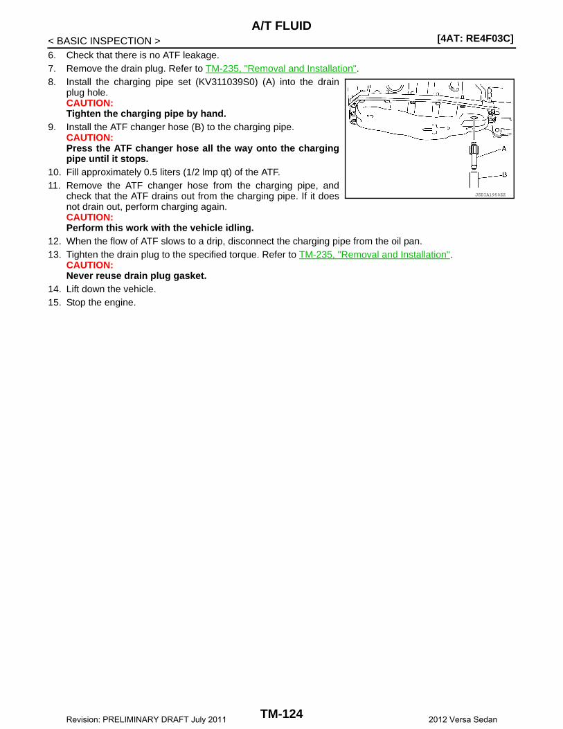
[4AT: RE4F03C]A/T FLUID
< BASIC INSPECTION >6. Check that there is no ATF leakage.7. Remove the drain plug. Refer to TM-235, "Removal and Installation".8. Install the charging pipe set (KV311039S0) (A) into the drain
plug hole.CAUTION:Tighten the charging pipe by hand.
9. Install the ATF changer hose (B) to the charging pipe.CAUTION:Press the ATF changer hose all the way onto the chargingpipe until it stops.
10. Fill approximately 0.5 liters (1/2 lmp qt) of the ATF.11. Remove the ATF changer hose from the charging pipe, and
check that the ATF drains out from the charging pipe. If it doesnot drain out, perform charging again.CAUTION:Perform this work with the vehicle idling.
12. When the flow of ATF slows to a drip, disconnect the charging pipe from the oil pan.13. Tighten the drain plug to the specified torque. Refer to TM-235, "Removal and Installation".
CAUTION:Never reuse drain plug gasket.
14. Lift down the vehicle.15. Stop the engine.
JSDIA1950ZZ
TM-124Revision: PRELIMINARY DRAFT July 2011 2012 Versa Sedan
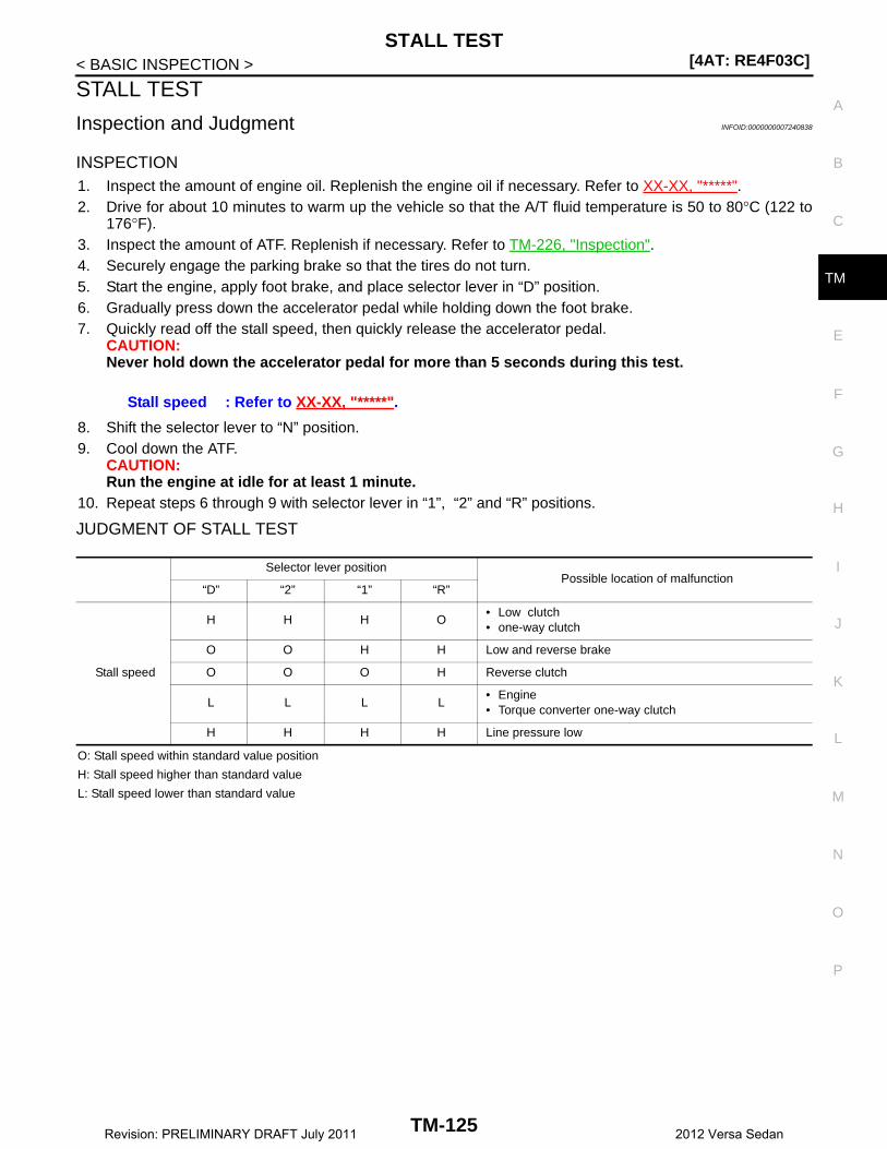
STALL TEST[4AT: RE4F03C]
C
E
F
G
H
I
J
K
L
M
A
B
M
N
O
P
< BASIC INSPECTION >
T
STALL TEST
Inspection and Judgment INFOID:0000000007240838
INSPECTION1. Inspect the amount of engine oil. Replenish the engine oil if necessary. Refer to XX-XX, "*****".2. Drive for about 10 minutes to warm up the vehicle so that the A/T fluid temperature is 50 to 80°C (122 to
176°F).3. Inspect the amount of ATF. Replenish if necessary. Refer to TM-226, "Inspection".4. Securely engage the parking brake so that the tires do not turn.5. Start the engine, apply foot brake, and place selector lever in “D” position.6. Gradually press down the accelerator pedal while holding down the foot brake.7. Quickly read off the stall speed, then quickly release the accelerator pedal.
CAUTION:Never hold down the accelerator pedal for more than 5 seconds during this test.
8. Shift the selector lever to “N” position.9. Cool down the ATF.
CAUTION:Run the engine at idle for at least 1 minute.
10. Repeat steps 6 through 9 with selector lever in “1”, “2” and “R” positions.
JUDGMENT OF STALL TEST
O: Stall speed within standard value position
H: Stall speed higher than standard value
L: Stall speed lower than standard value
Stall speed : Refer to XX-XX, "*****".
Selector lever positionPossible location of malfunction
“D” “2” “1” “R”
Stall speed
H H H O• Low clutch• one-way clutch
O O H H Low and reverse brake
O O O H Reverse clutch
L L L L• Engine• Torque converter one-way clutch
H H H H Line pressure low
TM-125Revision: PRELIMINARY DRAFT July 2011 2012 Versa Sedan

[4AT: RE4F03C]LINE PRESSURE TEST
< BASIC INSPECTION >
LINE PRESSURE TEST
Inspection and Judgment INFOID:0000000007240839
INSPECTION1. Inspect the amount of engine oil. Replenish the engine oil if necessary. Refer to LU-7, "Inspection".2. Drive for about 10 minutes to warm up the vehicle so that the A/T fluid temperature is to 50 to 80°C (122
to 176°F).3. Inspect the amount of ATF. Replenish if necessary. Refer to TM-226, "Inspection".4. Remove fluid pressure detection plug.
5. Install the joint pipe adapter (SST: KV31103600), adapter (SST:25054000), oil pressure gauge set (commercial service tool).NOTE:When using oil pressure gauge, be sure to use O-ring attachedto fluid pressure detection plug.
6. Securely engage parking brake so that the tires do not turn.7. Start the engine.8. Measure the line pressure at both idle and the stall speed.
CAUTION:Keep brake pedal pressed all the way down during measurement.
9. Install O-rig to fluid pressure detection plug.CAUTION:• Never reuse O-ring.• Apply ATF to O-ring.
10. Install fluid pressure detection plug.
JUDGMENT
1 : “D” position fluid pressure detection plug
2 : “R” position fluid pressure detection plug
Line pressure : XX-XX, "*****"
: 7.4 N·m (1.70 lb-m, 66 in-lb)
JSDIA2020ZZ
Judgment Possible cause
Idle speed
Low for all positions (“P”, “R”, “N”, “D”, “2”, “1”)
Possible causes include malfunctions in the pressure supply system and low oil pump output.For example• Oil pump wear• Pressure regulator valve or plug sticking or spring fatigue• Oil strainer ⇒ oil pump ⇒ pressure regulator valve passage oil leak• Engine idle speed too low
Only low for a specific position
Possible causes include an oil pressure leak in a passage or device related to the position after the pressure is distributed by the manual valve.
High
Possible causes include a sensor malfunction or malfunction in the line pressure adjustment function.For example• Accelerator pedal position signal malfunction• Line pressure solenoid malfunction (sticking in OFF state, filter clog, cut line)• Pressure regulator valve or plug sticking• Engine idle speed too high
TM-126Revision: PRELIMINARY DRAFT July 2011 2012 Versa Sedan

LINE PRESSURE TEST[4AT: RE4F03C]
C
E
F
G
H
I
J
K
L
M
A
B
M
N
O
P
< BASIC INSPECTION >
T
Stall speed
Line pressure does not rise higher than the line pressure for idle.
Possible causes include a sensor malfunction or malfunction in the pressure adjustment func-tion.For example• TCM malfunction• Line pressure solenoid malfunction (shorting, sticking in ON state)• Pressure regulator valve or plug sticking
The pressure rises, but does not enter the standard position.
Possible causes include malfunctions in the pressure supply system and malfunction in the pres-sure adjustment function.For example• Oil pump wear• Line pressure solenoid malfunction (sticking, filter clog)• Pressure regulator valve or plug sticking
Only low for a specific position
Possible causes include an oil pressure leak in a passage or device related to the position after the pressure is distributed by the manual valve.
Judgment Possible cause
TM-127Revision: PRELIMINARY DRAFT July 2011 2012 Versa Sedan

[4AT: RE4F03C]U0073 COMMUNICATION BUS A OFF
< DTC/CIRCUIT DIAGNOSIS >
DTC/CIRCUIT DIAGNOSISU0073 COMMUNICATION BUS A OFF
DTC Logic INFOID:0000000007240842
DTC DETECTION LOGIC
DTC CONFIRMATION PROCEDURE
1.PREPARATION BEFORE WORK
If another "DTC CONFIRMATION PROCEDURE" occurs just before, turn the ignition switch OFF and wait forat least 10 seconds, then perform the next test.
>> GO TO 2.
2.PERFORM DTC CONFIRMATION PROCEDURE
1. Start engine and wait for at least 5 seconds.2. Check the DTC.Is “U0073” detected?YES >> Go to TM-128, "Diagnosis Procedure".NO >> INSPECTION END
Diagnosis Procedure INFOID:0000000007240843
For the diagnosis procedure, refer to XX-XX, "*****".
DTC Trouble diagnosis name DTC detecting condition Possible causes
U0073Control Module Communication Bus “A” Off
When the ignition switch is ON, TCM detects a bus-off error continuously for 2 seconds or more.
Harness or connector(CAN communication line is open or shorted)
TM-128Revision: PRELIMINARY DRAFT July 2011 2012 Versa Sedan
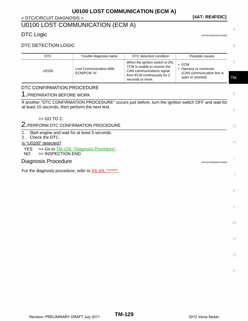
U0100 LOST COMMUNICATION (ECM A)[4AT: RE4F03C]
C
E
F
G
H
I
J
K
L
M
A
B
M
N
O
P
< DTC/CIRCUIT DIAGNOSIS >
T
U0100 LOST COMMUNICATION (ECM A)
DTC Logic INFOID:0000000007240845
DTC DETECTION LOGIC
DTC CONFIRMATION PROCEDURE
1.PREPARATION BEFORE WORK
If another "DTC CONFIRMATION PROCEDURE" occurs just before, turn the ignition switch OFF and wait forat least 10 seconds, then perform the next test.
>> GO TO 2.
2.PERFORM DTC CONFIRMATION PROCEDURE
1. Start engine and wait for at least 5 seconds.2. Check the DTC.Is “U0100” detected?YES >> Go to TM-129, "Diagnosis Procedure".NO >> INSPECTION END
Diagnosis Procedure INFOID:0000000007240846
For the diagnosis procedure, refer to XX-XX, "*****".
DTC Trouble diagnosis name DTC detection condition Possible causes
U0100Lost Communication With ECM/PCM “A”
When the ignition switch is ON, TCM is unable to receive the CAN communications signal from ECM continuously for 2 seconds or more.
• ECM• Harness or connector
(CAN communication line is open or shorted)
TM-129Revision: PRELIMINARY DRAFT July 2011 2012 Versa Sedan

[4AT: RE4F03C]U0140 LOST COMMUNICATION (BCM)
< DTC/CIRCUIT DIAGNOSIS >
U0140 LOST COMMUNICATION (BCM)
DTC Logic INFOID:0000000007240848
DTC DETECTION LOGIC
DTC CONFIRMATION PROCEDURE
1.PREPARATION BEFORE WORK
If another "DTC CONFIRMATION PROCEDURE" occurs just before, turn ignition switch OFF and wait for atleast 10 seconds, then perform the next test.
>> GO TO 2.
2.PERFORM DTC CONFIRMATION PROCEDURE
1. Start engine and wait for at least 5 seconds.2. Check the DTC.Is “U0140” detected?YES >> Go to TM-130, "Diagnosis Procedure".NO >> INSPECTION END
Diagnosis Procedure INFOID:0000000007240849
For the diagnosis procedure, refer to XX-XX, "*****".
DTC Trouble diagnosis name DTC detection condition Possible causes
U0140Lost Communication With Body Control Module
When the ignition switch is ON, TCM is unable to receive the CAN communications signal from BCM continuously for 2 seconds or more.
• BCM• Harness or connector
(CAN communication line is open or shorted)
TM-130Revision: PRELIMINARY DRAFT July 2011 2012 Versa Sedan

U0155 LOST COMMUNICATION (IPC)[4AT: RE4F03C]
C
E
F
G
H
I
J
K
L
M
A
B
M
N
O
P
< DTC/CIRCUIT DIAGNOSIS >
T
U0155 LOST COMMUNICATION (IPC)
DTC Logic INFOID:0000000007240851
DTC DETECTION LOGIC
DTC REPRODUCTION PROCEDURE
1.PREPARATION BEFORE WORK
If another "DTC CONFIRMATION PROCEDURE" occurs just before, turn ignition switch OFF and wait for atleast 10 seconds, then perform the next test.
>> GO TO 2.
2.PERFORM DTC CONFIRMATION PROCEDURE
1. Start engine and wait for at least 5 seconds.2. Check the DTC.Is “U0155” detected?YES >> Go to TM-131, "Diagnosis Procedure".NO >> INSPECTION END
Diagnosis Procedure INFOID:0000000007240852
For the diagnosis procedure, refer to XX-XX, "*****".
DTC Trouble diagnosis name DTC detecting condition Possible causes
U0155Lost Communication With In-strument Panel Cluster (IPC) Control Module
When the ignition switch is ON, TCM is unable to receive the CAN communications signal from the combination meter continuously for 2 seconds or more.
• Combination meter• Harness or connector
(CAN communication line is open or shorted)
TM-131Revision: PRELIMINARY DRAFT July 2011 2012 Versa Sedan
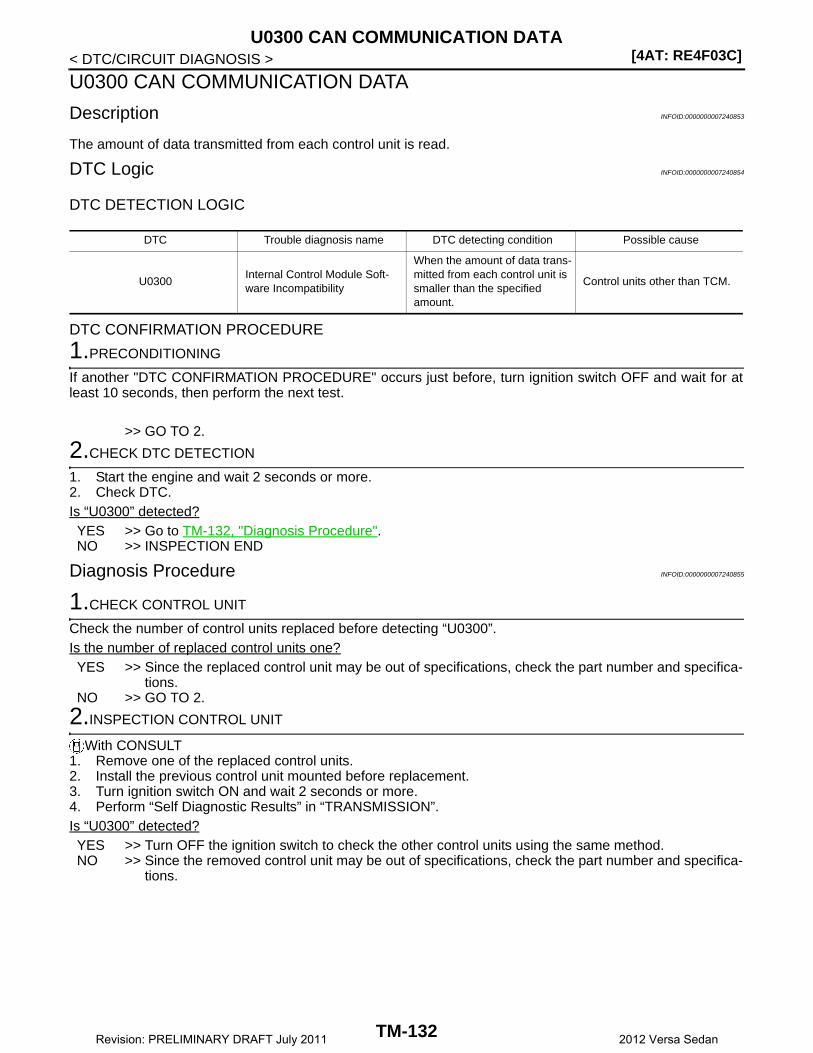
[4AT: RE4F03C]U0300 CAN COMMUNICATION DATA
< DTC/CIRCUIT DIAGNOSIS >
U0300 CAN COMMUNICATION DATA
Description INFOID:0000000007240853
The amount of data transmitted from each control unit is read.
DTC Logic INFOID:0000000007240854
DTC DETECTION LOGIC
DTC CONFIRMATION PROCEDURE
1.PRECONDITIONING
If another "DTC CONFIRMATION PROCEDURE" occurs just before, turn ignition switch OFF and wait for atleast 10 seconds, then perform the next test.
>> GO TO 2.
2.CHECK DTC DETECTION
1. Start the engine and wait 2 seconds or more.2. Check DTC.Is “U0300” detected?YES >> Go to TM-132, "Diagnosis Procedure".NO >> INSPECTION END
Diagnosis Procedure INFOID:0000000007240855
1.CHECK CONTROL UNIT
Check the number of control units replaced before detecting “U0300”.Is the number of replaced control units one?YES >> Since the replaced control unit may be out of specifications, check the part number and specifica-
tions.NO >> GO TO 2.
2.INSPECTION CONTROL UNIT
With CONSULT1. Remove one of the replaced control units.2. Install the previous control unit mounted before replacement.3. Turn ignition switch ON and wait 2 seconds or more.4. Perform “Self Diagnostic Results” in “TRANSMISSION”.Is “U0300” detected?YES >> Turn OFF the ignition switch to check the other control units using the same method.NO >> Since the removed control unit may be out of specifications, check the part number and specifica-
tions.
DTC Trouble diagnosis name DTC detecting condition Possible cause
U0300Internal Control Module Soft-ware Incompatibility
When the amount of data trans-mitted from each control unit is smaller than the specified amount.
Control units other than TCM.
TM-132Revision: PRELIMINARY DRAFT July 2011 2012 Versa Sedan
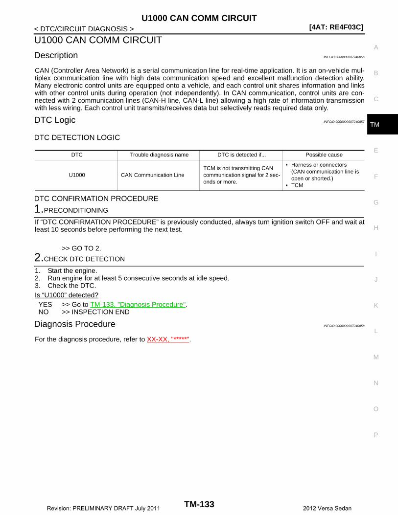
U1000 CAN COMM CIRCUIT[4AT: RE4F03C]
C
E
F
G
H
I
J
K
L
M
A
B
M
N
O
P
< DTC/CIRCUIT DIAGNOSIS >
T
U1000 CAN COMM CIRCUIT
Description INFOID:0000000007240856
CAN (Controller Area Network) is a serial communication line for real-time application. It is an on-vehicle mul-tiplex communication line with high data communication speed and excellent malfunction detection ability.Many electronic control units are equipped onto a vehicle, and each control unit shares information and linkswith other control units during operation (not independently). In CAN communication, control units are con-nected with 2 communication lines (CAN-H line, CAN-L line) allowing a high rate of information transmissionwith less wiring. Each control unit transmits/receives data but selectively reads required data only.
DTC Logic INFOID:0000000007240857
DTC DETECTION LOGIC
DTC CONFIRMATION PROCEDURE
1.PRECONDITIONING
If “DTC CONFIRMATION PROCEDURE” is previously conducted, always turn ignition switch OFF and wait atleast 10 seconds before performing the next test.
>> GO TO 2.
2.CHECK DTC DETECTION
1. Start the engine.2. Run engine for at least 5 consecutive seconds at idle speed.3. Check the DTC.Is “U1000” detected?YES >> Go to TM-133, "Diagnosis Procedure".NO >> INSPECTION END
Diagnosis Procedure INFOID:0000000007240858
For the diagnosis procedure, refer to XX-XX, "*****".
DTC Trouble diagnosis name DTC is detected if... Possible cause
U1000 CAN Communication LineTCM is not transmitting CAN communication signal for 2 sec-onds or more.
• Harness or connectors(CAN communication line is open or shorted.)
• TCM
TM-133Revision: PRELIMINARY DRAFT July 2011 2012 Versa Sedan

[4AT: RE4F03C]U1117 LOST COMMUNICATION (ABS)
< DTC/CIRCUIT DIAGNOSIS >
U1117 LOST COMMUNICATION (ABS)
DTC Logic INFOID:0000000007240860
DTC DETECTION LOGIC
DTC CONFIRMATION PROCEDURE
1.PREPARATION BEFORE WORK
If another "DTC CONFIRMATION PROCEDURE" occurs just before, turn the ignition switch OFF and wait forat least 10 seconds, then perform the next test.
>> GO TO 2.
2.PERFORM DTC CONFIRMATION PROCEDURE
1. Turn ignition switch ON, and wait for 5 seconds or more.2. Check the DTC.Is “U1117” detected?YES >> Go to TM-134, "Diagnosis Procedure".NO >> INSPECTION END
Diagnosis Procedure INFOID:0000000007240861
For the diagnosis procedure, refer to XX-XX, "*****".
DTC Trouble diagnosis name DTC detecting condition Possible causes
U1117 Lost Communication With ABS
When the ignition switch is ON, TCM is unable to receive the CAN communications signal from ABS actuator control unit continuously for 2 seconds or more.
• ABS actuator & control mod-ule
• Harness or connector(CAN communication line is open or shorted)
TM-134Revision: PRELIMINARY DRAFT July 2011 2012 Versa Sedan
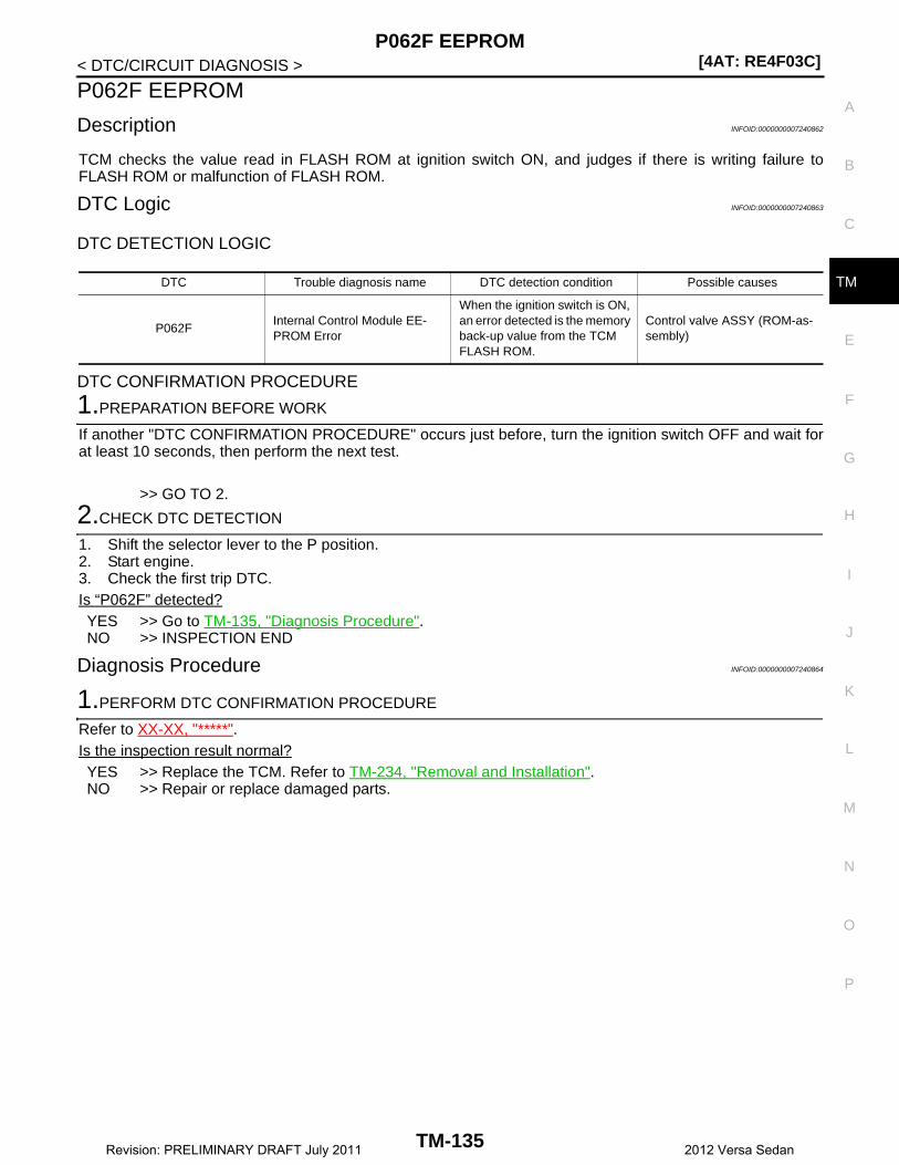
P062F EEPROM[4AT: RE4F03C]
C
E
F
G
H
I
J
K
L
M
A
B
M
N
O
P
< DTC/CIRCUIT DIAGNOSIS >
T
P062F EEPROM
Description INFOID:0000000007240862
TCM checks the value read in FLASH ROM at ignition switch ON, and judges if there is writing failure toFLASH ROM or malfunction of FLASH ROM.
DTC Logic INFOID:0000000007240863
DTC DETECTION LOGIC
DTC CONFIRMATION PROCEDURE
1.PREPARATION BEFORE WORK
If another "DTC CONFIRMATION PROCEDURE" occurs just before, turn the ignition switch OFF and wait forat least 10 seconds, then perform the next test.
>> GO TO 2.
2.CHECK DTC DETECTION
1. Shift the selector lever to the P position.2. Start engine.3. Check the first trip DTC.Is “P062F” detected?YES >> Go to TM-135, "Diagnosis Procedure".NO >> INSPECTION END
Diagnosis Procedure INFOID:0000000007240864
1.PERFORM DTC CONFIRMATION PROCEDURE
Refer to XX-XX, "*****".Is the inspection result normal?YES >> Replace the TCM. Refer to TM-234, "Removal and Installation".NO >> Repair or replace damaged parts.
DTC Trouble diagnosis name DTC detection condition Possible causes
P062FInternal Control Module EE-PROM Error
When the ignition switch is ON, an error detected is the memory back-up value from the TCM FLASH ROM.
Control valve ASSY (ROM-as-sembly)
TM-135Revision: PRELIMINARY DRAFT July 2011 2012 Versa Sedan

[4AT: RE4F03C]P0705 TRANSMISSION RANGE SWITCH A
< DTC/CIRCUIT DIAGNOSIS >
P0705 TRANSMISSION RANGE SWITCH A
DTC Logic INFOID:0000000007240865
DTC DETECTION LOGIC
DTC CONFIRMATION PROCEDURE
1.PREPARATION BEFORE WORK
If another "DTC CONFIRMATION PROCEDURE" occurs just before, turn the ignition switch OFF and wait forat least 10 seconds, then perform the next test.
>> GO TO 2.
2.CHECK DTC DETECTION
1. Turn ignition switch ON.2. Shift the selector lever to the entire position from P to 1. (Hold the selector lever at each position for 10
seconds or more.)3. Check the first trip DTC.Is “P0705” detected?YES >> Go to TM-136, "Diagnosis Procedure".NO >> INSPECTION END
Diagnosis Procedure INFOID:0000000007240866
1.CHECK TCM INPUT SIGNALS
With CONSULT1. Turn ignition switch ON.2. Select “TRANSMISSION” “DATA MONITOR”.3. Select the “D position switch”, “N position switch”, “R position switch”, “P position switch”, “2 position
switch”, and “1 position switch”.4. Shift the selector lever to the entire position from P to 1, and check the ON/OFF operation of each monitor
item.
DTC Trouble diagnosis name DTC detection condition Possible causes
P0705Transmission Range Sensor “A” Circuit Malfunction (PRNDL input)
The following diagnosis condi-tions are met and 2 or more po-sition signals are ON at the same time for 5 seconds or more.• Diagnosis condition- TCM power supply voltage:
10 V <TCM power supply voltage <16 V
• Harness or connector(Short circuit between trans-mission position SW and TCM)
• Transmission range switch
Monitor item Condition Status
RANGE SW 1Selector lever in “1” position On
Other than the above Off
RANGE SW 2Selector lever in “2” position On
Other than the above Off
RANGE SW DSelector lever in “D” position On
Other than the above Off
RANGE SW NSelector lever in “N” position On
Other than the above Off
RANGE SW RSelector lever in “R” position On
Other than the above Off
TM-136Revision: PRELIMINARY DRAFT July 2011 2012 Versa Sedan

P0705 TRANSMISSION RANGE SWITCH A[4AT: RE4F03C]
C
E
F
G
H
I
J
K
L
M
A
B
M
N
O
P
< DTC/CIRCUIT DIAGNOSIS >
T
Without CONSULT.1. Turn ignition switch OFF.2. Disconnect the TCM connector.3. Turn ignition switch ON.4. Shift the selector lever to the entire position from P to 1, and check the voltage between the TCM harness
connector terminal and ground.
Is the check result normal?YES >> Check intermittent incident. Refer to XX-XX, "*****".NO-1 [D position SW is “On” when selector is not in D position. (Or, connector terminal 4 is at 10 - 16 V.)]>>
GO TO 2.NO-2 [N position SW is “On” when selector is not in N position. (Or, connector terminal 5 is at 10 - 16 V.)]>>
GO TO 4.NO-3 [R position SW is “On” when selector is not in R position. (Or, connector terminal 6 is at 10 - 16 V.)]>>
GO TO 6.NO-4 [P position SW is “On” when selector is not in P position. (Or, connector terminal 7 is at 10 - 16 V.)]>>
GO TO 8.NO-5 [2 position SW is “On” when selector is not in 2 position. (Or, connector terminal 3 is at 10 - 16 V.)]>>
GO TO 10.NO-6 [1 position SW is “On” when selector is not in 1 position. (Or, connector terminal 2 is at 10 - 16 V.)]>>
GO TO 12.
2.CHECK D POSITION SW CIRCUIT (CHECK 1)
1. Turn ignition switch OFF.2. Disconnect the TCM connector.3. Check the continuity between the TCM harness connector terminals.
RANGE SW PSelector lever in “P” position On
Other than the above Off
Monitor item Condition Status
TCM harness connectorGround Condition Voltage
Connector Terminal
F44
2
Ground
Selector lever in “1” posi-tion
10 - 16 V
Other than the above Approx. 0 V
3
Selector lever in “2” posi-tion
10 - 16 V
Other than the above Approx. 0 V
4
Selector lever in “D” po-sition
10 - 16 V
Other than the above Approx. 0 V
5
Selector lever in “N” po-sition
10 - 16 V
Other than the above Approx. 0 V
6
Selector lever in “R” po-sition
10 - 16 V
Other than the above Approx. 0 V
7
Selector lever in “P” posi-tion
10 - 16 V
Other than the above Approx. 0 V
TM-137Revision: PRELIMINARY DRAFT July 2011 2012 Versa Sedan
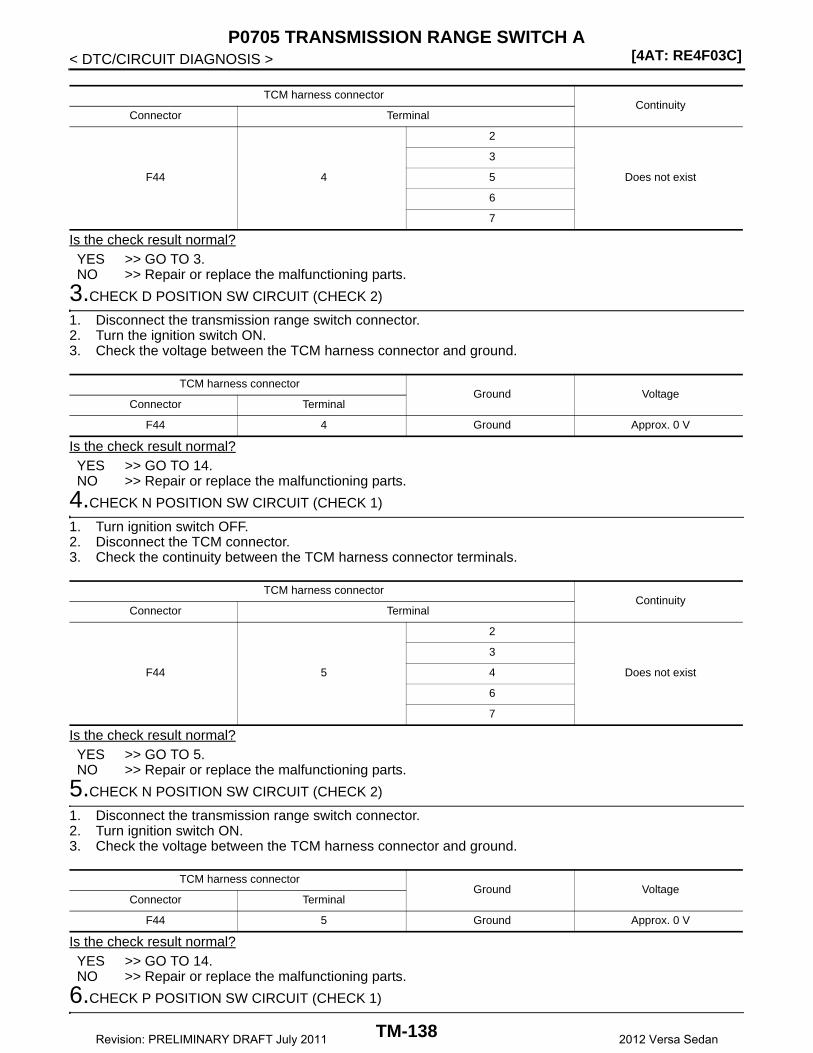
[4AT: RE4F03C]P0705 TRANSMISSION RANGE SWITCH A
< DTC/CIRCUIT DIAGNOSIS >
Is the check result normal?YES >> GO TO 3.NO >> Repair or replace the malfunctioning parts.
3.CHECK D POSITION SW CIRCUIT (CHECK 2)
1. Disconnect the transmission range switch connector.2. Turn the ignition switch ON.3. Check the voltage between the TCM harness connector and ground.
Is the check result normal?YES >> GO TO 14.NO >> Repair or replace the malfunctioning parts.
4.CHECK N POSITION SW CIRCUIT (CHECK 1)
1. Turn ignition switch OFF.2. Disconnect the TCM connector.3. Check the continuity between the TCM harness connector terminals.
Is the check result normal?YES >> GO TO 5.NO >> Repair or replace the malfunctioning parts.
5.CHECK N POSITION SW CIRCUIT (CHECK 2)
1. Disconnect the transmission range switch connector.2. Turn ignition switch ON.3. Check the voltage between the TCM harness connector and ground.
Is the check result normal?YES >> GO TO 14.NO >> Repair or replace the malfunctioning parts.
6.CHECK P POSITION SW CIRCUIT (CHECK 1)
TCM harness connectorContinuity
Connector Terminal
F44 4
2
Does not exist
3
5
6
7
TCM harness connectorGround Voltage
Connector Terminal
F44 4 Ground Approx. 0 V
TCM harness connectorContinuity
Connector Terminal
F44 5
2
Does not exist
3
4
6
7
TCM harness connectorGround Voltage
Connector Terminal
F44 5 Ground Approx. 0 V
TM-138Revision: PRELIMINARY DRAFT July 2011 2012 Versa Sedan

P0705 TRANSMISSION RANGE SWITCH A[4AT: RE4F03C]
C
E
F
G
H
I
J
K
L
M
A
B
M
N
O
P
< DTC/CIRCUIT DIAGNOSIS >
T
1. Turn ignition switch OFF.2. Disconnect the TCM connector.3. Check the continuity between the TCM harness connector terminals.
Is the check result normal?YES >> GO TO 7.NO >> Repair or replace the malfunctioning parts.
7.CHECK P POSITION SW CIRCUIT (CHECK 2)
1. Disconnect the transmission range switch connector.2. Turn ignition switch ON.3. Check the voltage between the TCM harness connector and ground.
Is the check result normal?YES >> GO TO 14.NO >> Repair or replace the malfunctioning parts.
8.CHECK R POSITION SW CIRCUIT (CHECK 1)
1. Turn ignition switch OFF.2. Disconnect the TCM connector.3. Check the continuity between the TCM harness connector terminals.
Is the check result normal?YES >> GO TO 9.NO >> Repair or replace the malfunctioning parts.
9.CHECK R POSITION SW CIRCUIT (CHECK 2)
1. Disconnect the transmission range switch connector.2. Turn ignition switch ON.3. Check the voltage between the TCM harness connector and ground.
Is the check result normal?
TCM harness connectorContinuity
Connector Terminal
F44 7
2
Does not exist
3
4
5
6
TCM harness connectorGround Voltage
Connector Terminal
F44 7 Ground Approx. 0 V
TCM harness connectorContinuity
Connector Terminal
F44 6
2
Does not exist
3
4
5
7
TCM harness connectorGround Voltage
Connector Terminal
F44 6 Ground Approx. 0 V
TM-139Revision: PRELIMINARY DRAFT July 2011 2012 Versa Sedan
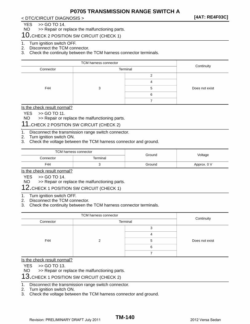
[4AT: RE4F03C]P0705 TRANSMISSION RANGE SWITCH A
< DTC/CIRCUIT DIAGNOSIS >YES >> GO TO 14.NO >> Repair or replace the malfunctioning parts.
10.CHECK 2 POSITION SW CIRCUIT (CHECK 1)
1. Turn ignition switch OFF.2. Disconnect the TCM connector.3. Check the continuity between the TCM harness connector terminals.
Is the check result normal?YES >> GO TO 11.NO >> Repair or replace the malfunctioning parts.
11.CHECK 2 POSITION SW CIRCUIT (CHECK 2)
1. Disconnect the transmission range switch connector.2. Turn ignition switch ON.3. Check the voltage between the TCM harness connector and ground.
Is the check result normal?YES >> GO TO 14.NO >> Repair or replace the malfunctioning parts.
12.CHECK 1 POSITION SW CIRCUIT (CHECK 1)
1. Turn ignition switch OFF.2. Disconnect the TCM connector.3. Check the continuity between the TCM harness connector terminals.
Is the check result normal?YES >> GO TO 13.NO >> Repair or replace the malfunctioning parts.
13.CHECK 1 POSITION SW CIRCUIT (CHECK 2)
1. Disconnect the transmission range switch connector.2. Turn ignition switch ON.3. Check the voltage between the TCM harness connector and ground.
TCM harness connectorContinuity
Connector Terminal
F44 3
2
Does not exist
4
5
6
7
TCM harness connectorGround Voltage
Connector Terminal
F44 3 Ground Approx. 0 V
TCM harness connectorContinuity
Connector Terminal
F44 2
3
Does not exist
4
5
6
7
TM-140Revision: PRELIMINARY DRAFT July 2011 2012 Versa Sedan

P0705 TRANSMISSION RANGE SWITCH A[4AT: RE4F03C]
C
E
F
G
H
I
J
K
L
M
A
B
M
N
O
P
< DTC/CIRCUIT DIAGNOSIS >
T
Is the check result normal?YES >> GO TO 14.NO >> Repair or replace the malfunctioning parts.
14.CHECK TRANSMISSION RANGE SWITCH
Check the transmission range switch. Refer to TM-141, "Component Inspection (Transmission RangeSwitch)".Is the check result normal?YES >> Check intermittent incident. Refer to XX-XX, "*****".NO >> Repair or replace the malfunctioning parts.
Component Inspection (Transmission Range Switch) INFOID:0000000007240867
1.CHECK TRANSMISSION RANGE SWITCH
Check the continuity between the transmission range switch connector terminals.
Is the check result normal?YES >> INSPECTION ENDNO >> There is a malfunction of the transmission range switch. Replace the transaxle assembly. Refer to
TM-242, "Removal and Installation".
TCM harness connectorGround Voltage
Connector Terminal
F44 2 Ground Approx. 0 V
Transmission range switchCondition Continuity
Terminal
7 10
Selector lever in “P”, “N” posi-tion
Exists
Other than the above Does not exist
6
9Selector lever in “1” position Exists
Other than the above Does not exist
5Selector lever in “2” position Exists
Other than the above Does not exist
8Selector lever in “D” position Exists
Other than the above Does not exist
4Selector lever in “N” position Exists
Other than the above Does not exist
2Selector lever in “R” position Exists
Other than the above Does not exist
3Selector lever in “P” position Exists
Other than the above Does not exist
TM-141Revision: PRELIMINARY DRAFT July 2011 2012 Versa Sedan
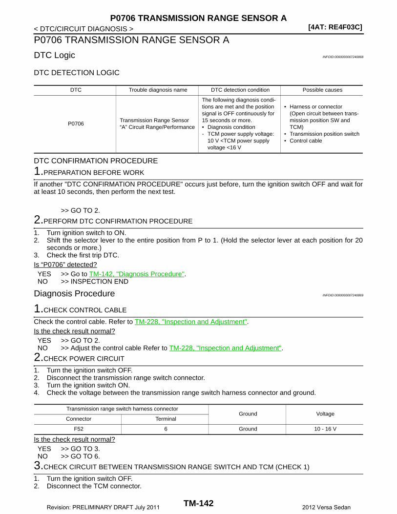
[4AT: RE4F03C]P0706 TRANSMISSION RANGE SENSOR A
< DTC/CIRCUIT DIAGNOSIS >
P0706 TRANSMISSION RANGE SENSOR A
DTC Logic INFOID:0000000007240868
DTC DETECTION LOGIC
DTC CONFIRMATION PROCEDURE
1.PREPARATION BEFORE WORK
If another "DTC CONFIRMATION PROCEDURE" occurs just before, turn the ignition switch OFF and wait forat least 10 seconds, then perform the next test.
>> GO TO 2.
2.PERFORM DTC CONFIRMATION PROCEDURE
1. Turn ignition switch to ON.2. Shift the selector lever to the entire position from P to 1. (Hold the selector lever at each position for 20
seconds or more.)3. Check the first trip DTC.Is “P0706” detected?YES >> Go to TM-142, "Diagnosis Procedure".NO >> INSPECTION END
Diagnosis Procedure INFOID:0000000007240869
1.CHECK CONTROL CABLE
Check the control cable. Refer to TM-228, "Inspection and Adjustment".Is the check result normal?YES >> GO TO 2.NO >> Adjust the control cable Refer to TM-228, "Inspection and Adjustment".
2.CHECK POWER CIRCUIT
1. Turn the ignition switch OFF.2. Disconnect the transmission range switch connector.3. Turn the ignition switch ON.4. Check the voltage between the transmission range switch harness connector and ground.
Is the check result normal?YES >> GO TO 3.NO >> GO TO 6.
3.CHECK CIRCUIT BETWEEN TRANSMISSION RANGE SWITCH AND TCM (CHECK 1)
1. Turn the ignition switch OFF.2. Disconnect the TCM connector.
DTC Trouble diagnosis name DTC detection condition Possible causes
P0706Transmission Range Sensor “A” Circuit Range/Performance
The following diagnosis condi-tions are met and the position signal is OFF continuously for 15 seconds or more.• Diagnosis condition- TCM power supply voltage:
10 V <TCM power supply voltage <16 V
• Harness or connector(Open circuit between trans-mission position SW and TCM)
• Transmission position switch• Control cable
Transmission range switch harness connectorGround Voltage
Connector Terminal
F52 6 Ground 10 - 16 V
TM-142Revision: PRELIMINARY DRAFT July 2011 2012 Versa Sedan
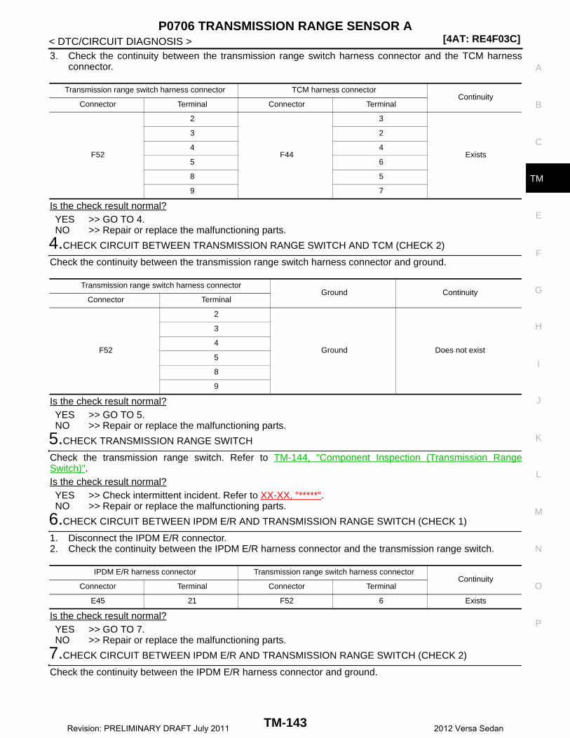
P0706 TRANSMISSION RANGE SENSOR A[4AT: RE4F03C]
C
E
F
G
H
I
J
K
L
M
A
B
M
N
O
P
< DTC/CIRCUIT DIAGNOSIS >
T
3. Check the continuity between the transmission range switch harness connector and the TCM harnessconnector.
Is the check result normal?YES >> GO TO 4.NO >> Repair or replace the malfunctioning parts.
4.CHECK CIRCUIT BETWEEN TRANSMISSION RANGE SWITCH AND TCM (CHECK 2)
Check the continuity between the transmission range switch harness connector and ground.
Is the check result normal?YES >> GO TO 5.NO >> Repair or replace the malfunctioning parts.
5.CHECK TRANSMISSION RANGE SWITCH
Check the transmission range switch. Refer to TM-144, "Component Inspection (Transmission RangeSwitch)".Is the check result normal?YES >> Check intermittent incident. Refer to XX-XX, "*****".NO >> Repair or replace the malfunctioning parts.
6.CHECK CIRCUIT BETWEEN IPDM E/R AND TRANSMISSION RANGE SWITCH (CHECK 1)
1. Disconnect the IPDM E/R connector.2. Check the continuity between the IPDM E/R harness connector and the transmission range switch.
Is the check result normal?YES >> GO TO 7.NO >> Repair or replace the malfunctioning parts.
7.CHECK CIRCUIT BETWEEN IPDM E/R AND TRANSMISSION RANGE SWITCH (CHECK 2)
Check the continuity between the IPDM E/R harness connector and ground.
Transmission range switch harness connector TCM harness connectorContinuity
Connector Terminal Connector Terminal
F52
2
F44
3
Exists
3 2
4 4
5 6
8 5
9 7
Transmission range switch harness connectorGround Continuity
Connector Terminal
F52
2
Ground Does not exist
3
4
5
8
9
IPDM E/R harness connector Transmission range switch harness connectorContinuity
Connector Terminal Connector Terminal
E45 21 F52 6 Exists
TM-143Revision: PRELIMINARY DRAFT July 2011 2012 Versa Sedan

[4AT: RE4F03C]P0706 TRANSMISSION RANGE SENSOR A
< DTC/CIRCUIT DIAGNOSIS >
Is the check result normal?YES >> GO TO 8.NO >> Repair or replace the malfunctioning parts.
8.DETECTION OF MALFUNCTION ITEMS
Check the following items:• Harness open circuit or short circuit between the ignition switch and IPDM E/R. Refer to XX-XX, "*****".• 10 A fuse (#49, IPDM E/R). Refer to XX-XX, "*****".• IPDM E/RIs the check result normal?YES >> Check intermittent incident. Refer to XX-XX, "*****".NO >> Repair or replace the malfunctioning parts.
Component Inspection (Transmission Range Switch) INFOID:0000000007240870
1.CHECK TRANSMISSION RANGE SWITCH
Check the continuity between the transmission range switch connector terminals.
Is the check result normal?YES >> INSPECTION ENDNO >> There is a malfunction of the transmission range switch. Replace the transaxle assembly. Refer to
TM-242, "Removal and Installation".
IPDM E/R harness connectorGround Continuity
Connector Terminal
E45 21 Ground Does not exist
Transmission range switchCondition Continuity
Terminal
7 10
Selector lever in “P”, “N” posi-tion
Exists
Other than the above Does not exist
6
9Selector lever in “1” position Exists
Other than the above Does not exist
5Selector lever in “2” position Exists
Other than the above Does not exist
8Selector lever in “D” position Exists
Other than the above Does not exist
4Selector lever in “N” position Exists
Other than the above Does not exist
2Selector lever in “R” position Exists
Other than the above Does not exist
3Selector lever in “P” position Exists
Other than the above Does not exist
TM-144Revision: PRELIMINARY DRAFT July 2011 2012 Versa Sedan
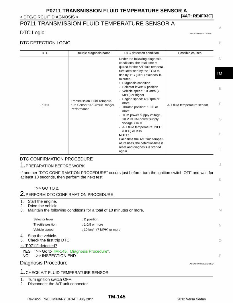
P0711 TRANSMISSION FLUID TEMPERATURE SENSOR A[4AT: RE4F03C]
C
E
F
G
H
I
J
K
L
M
A
B
M
N
O
P
< DTC/CIRCUIT DIAGNOSIS >
T
P0711 TRANSMISSION FLUID TEMPERATURE SENSOR A
DTC Logic INFOID:0000000007240871
DTC DETECTION LOGIC
DTC CONFIRMATION PROCEDURE
1.PREPARATION BEFORE WORK
If another "DTC CONFIRMATION PROCEDURE" occurs just before, turn the ignition switch OFF and wait forat least 10 seconds, then perform the next test.
>> GO TO 2.
2.PERFORM DTC CONFIRMATION PROCEDURE
1. Start the engine.2. Drive the vehicle.3. Maintain the following conditions for a total of 10 minutes or more.
4. Stop the vehicle.5. Check the first trip DTC.Is “P0711” detected?YES >> Go to TM-145, "Diagnosis Procedure".NO >> INSPECTION END
Diagnosis Procedure INFOID:0000000007240872
1.CHECK A/T FLUID TEMPERATURE SENSOR
1. Turn ignition switch OFF.2. Disconnect the A/T unit connector.
DTC Trouble diagnosis name DTC detection condition Possible causes
P0711Transmission Fluid Tempera-ture Sensor “A” Circuit Range/Performance
Under the following diagnosis conditions, the total time re-quired for the A/T fluid tempera-ture identified by the TCM to rise by 1°C (34°F) exceeds 10 minutes.• Diagnosis condition- Selector lever: D position- Vehicle speed: 10 km/h (7
MPH) or higher- Engine speed: 450 rpm or
more- Throttle position: 1.0/8 or
more- TCM power supply voltage:
10 V <TCM power supply voltage <16 V
- A/T fluid temperature: 20°C (68°F) or less
NOTE:Each time the A/T fluid temper-ature rises, the detection time is reset and diagnosis is started again.
A/T fluid temperature sensor
Selector lever : D position
Throttle position : 1.0/8 or more
Vehicle speed : 10 km/h (7 MPH) or more
TM-145Revision: PRELIMINARY DRAFT July 2011 2012 Versa Sedan
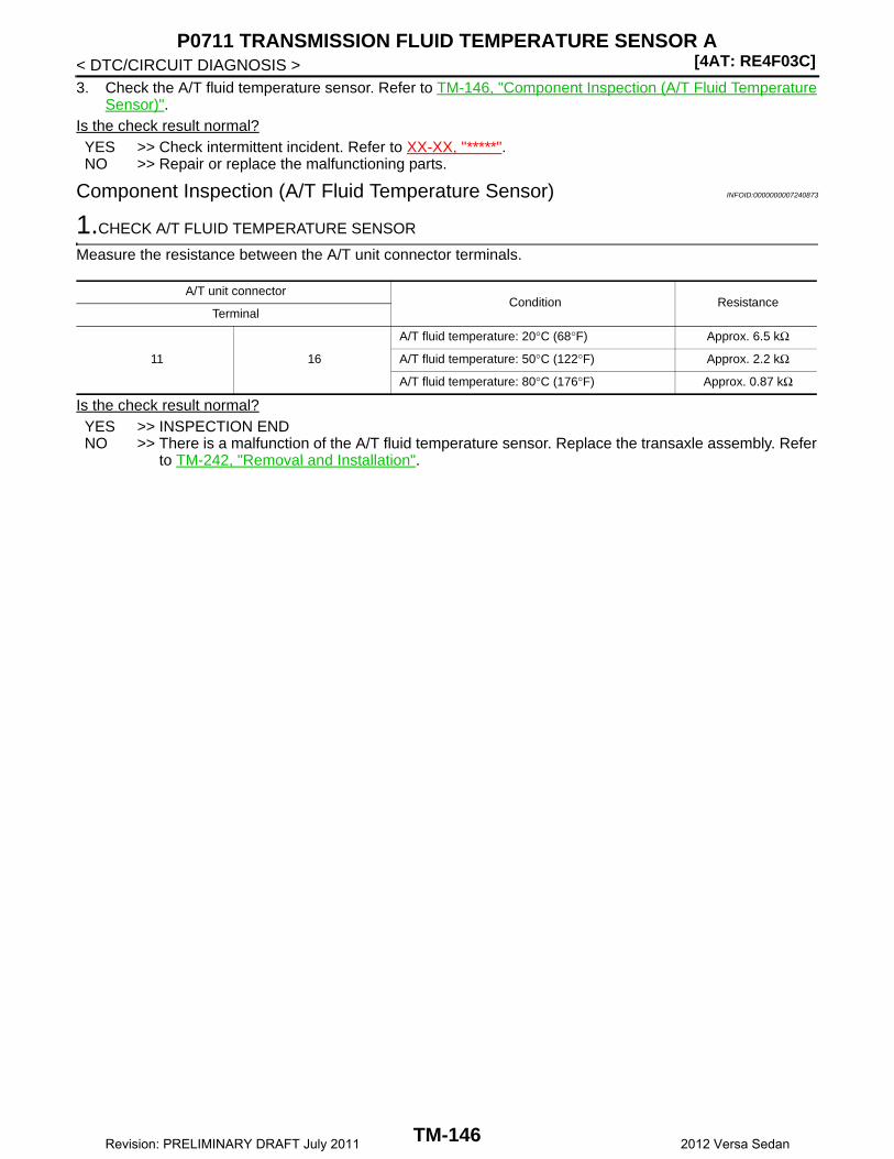
[4AT: RE4F03C]P0711 TRANSMISSION FLUID TEMPERATURE SENSOR A
< DTC/CIRCUIT DIAGNOSIS >3. Check the A/T fluid temperature sensor. Refer to TM-146, "Component Inspection (A/T Fluid Temperature
Sensor)".Is the check result normal?YES >> Check intermittent incident. Refer to XX-XX, "*****".NO >> Repair or replace the malfunctioning parts.
Component Inspection (A/T Fluid Temperature Sensor) INFOID:0000000007240873
1.CHECK A/T FLUID TEMPERATURE SENSOR
Measure the resistance between the A/T unit connector terminals.
Is the check result normal?YES >> INSPECTION ENDNO >> There is a malfunction of the A/T fluid temperature sensor. Replace the transaxle assembly. Refer
to TM-242, "Removal and Installation".
A/T unit connectorCondition Resistance
Terminal
11 16
A/T fluid temperature: 20°C (68°F) Approx. 6.5 kΩ
A/T fluid temperature: 50°C (122°F) Approx. 2.2 kΩ
A/T fluid temperature: 80°C (176°F) Approx. 0.87 kΩ
TM-146Revision: PRELIMINARY DRAFT July 2011 2012 Versa Sedan
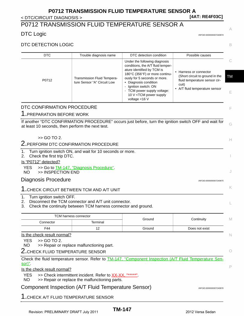
P0712 TRANSMISSION FLUID TEMPERATURE SENSOR A[4AT: RE4F03C]
C
E
F
G
H
I
J
K
L
M
A
B
M
N
O
P
< DTC/CIRCUIT DIAGNOSIS >
T
P0712 TRANSMISSION FLUID TEMPERATURE SENSOR A
DTC Logic INFOID:0000000007240874
DTC DETECTION LOGIC
DTC CONFIRMATION PROCEDURE
1.PREPARATION BEFORE WORK
If another “DTC CONFIRMATION PROCEDURE” occurs just before, turn the ignition switch OFF and wait forat least 10 seconds, then perform the next test.
>> GO TO 2.
2.PERFORM DTC CONFIRMATION PROCEDURE
1. Turn ignition switch ON, and wait for 10 seconds or more.2. Check the first trip DTC.Is “P0712” detected?YES >> Go to TM-147, "Diagnosis Procedure".NO >> INSPECTION END
Diagnosis Procedure INFOID:0000000007240875
1.CHECK CIRCUIT BETWEEN TCM AND A/T UNIT
1. Turn ignition switch OFF.2. Disconnect the TCM connector and A/T unit connector. 3. Check the continuity between TCM harness connector and ground.
Is the check result normal?YES >> GO TO 2.NO >> Repair or replace malfunctioning part.
2.CHECK FLUID TEMPERATURE SENSOR
Check the fluid temperature sensor. Refer to TM-147, "Component Inspection (A/T Fluid Temperature Sen-sor)".Is the check result normal?YES >> Check intermittent incident. Refer to XX-XX, "*****".NO >> Repair or replace the malfunctioning parts.
Component Inspection (A/T Fluid Temperature Sensor) INFOID:0000000007240876
1.CHECK A/T FLUID TEMPERATURE SENSOR
DTC Trouble diagnosis name DTC detection condition Possible causes
P0712Transmission Fluid Tempera-ture Sensor “A” Circuit Low
Under the following diagnosis conditions, the A/T fluid temper-ature identified by TCM is 180°C (356°F) or more continu-ously for 5 seconds or more.• Diagnosis condition- Ignition switch: ON- TCM power supply voltage:
10 V <TCM power supply voltage <16 V
• Harness or connector(Short circuit to ground in the fluid temperature sensor cir-cuit)
• A/T fluid temperature sensor
TCM harness connectorGround Continuity
Connector Terminal
F44 12 Ground Does not exist
TM-147Revision: PRELIMINARY DRAFT July 2011 2012 Versa Sedan

[4AT: RE4F03C]P0712 TRANSMISSION FLUID TEMPERATURE SENSOR A
< DTC/CIRCUIT DIAGNOSIS >Measure the resistance between the A/T unit connector terminals.
Is the check result normal?YES >> INSPECTION ENDNO >> There is a malfunction of the A/T fluid temperature sensor. Replace the transaxle assembly. Refer
to TM-242, "Removal and Installation".
A/T unit connectorCondition Resistance
Terminal
11 16
A/T fluid temperature: 20°C (68°F) Approx. 6.5 kΩ
A/T fluid temperature: 50°C (122°F) Approx. 2.2 kΩ
A/T fluid temperature: 80°C (176°F) Approx. 0.87 kΩ
TM-148Revision: PRELIMINARY DRAFT July 2011 2012 Versa Sedan
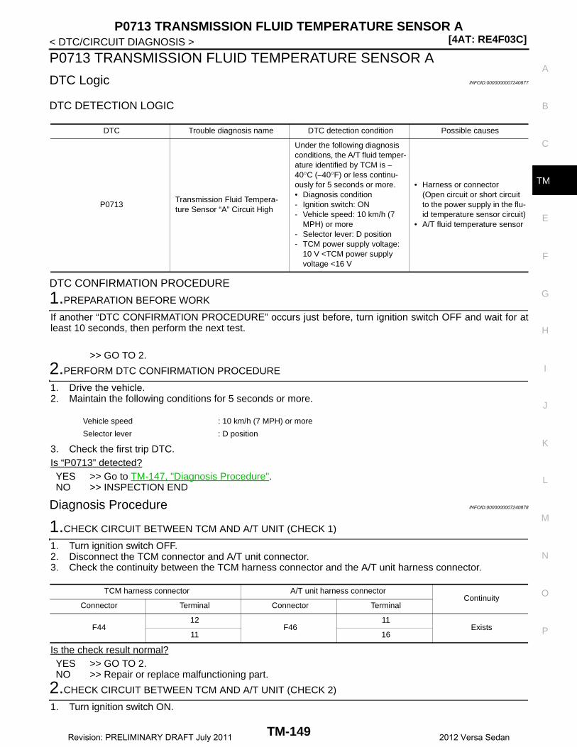
P0713 TRANSMISSION FLUID TEMPERATURE SENSOR A[4AT: RE4F03C]
C
E
F
G
H
I
J
K
L
M
A
B
M
N
O
P
< DTC/CIRCUIT DIAGNOSIS >
T
P0713 TRANSMISSION FLUID TEMPERATURE SENSOR A
DTC Logic INFOID:0000000007240877
DTC DETECTION LOGIC
DTC CONFIRMATION PROCEDURE
1.PREPARATION BEFORE WORK
If another “DTC CONFIRMATION PROCEDURE” occurs just before, turn ignition switch OFF and wait for atleast 10 seconds, then perform the next test.
>> GO TO 2.
2.PERFORM DTC CONFIRMATION PROCEDURE
1. Drive the vehicle.2. Maintain the following conditions for 5 seconds or more.
3. Check the first trip DTC.Is “P0713” detected?YES >> Go to TM-147, "Diagnosis Procedure".NO >> INSPECTION END
Diagnosis Procedure INFOID:0000000007240878
1.CHECK CIRCUIT BETWEEN TCM AND A/T UNIT (CHECK 1)
1. Turn ignition switch OFF.2. Disconnect the TCM connector and A/T unit connector. 3. Check the continuity between the TCM harness connector and the A/T unit harness connector.
Is the check result normal?YES >> GO TO 2.NO >> Repair or replace malfunctioning part.
2.CHECK CIRCUIT BETWEEN TCM AND A/T UNIT (CHECK 2)
1. Turn ignition switch ON.
DTC Trouble diagnosis name DTC detection condition Possible causes
P0713Transmission Fluid Tempera-ture Sensor “A” Circuit High
Under the following diagnosis conditions, the A/T fluid temper-ature identified by TCM is −40°C (−40°F) or less continu-ously for 5 seconds or more.• Diagnosis condition- Ignition switch: ON- Vehicle speed: 10 km/h (7
MPH) or more- Selector lever: D position- TCM power supply voltage:
10 V <TCM power supply voltage <16 V
• Harness or connector(Open circuit or short circuit to the power supply in the flu-id temperature sensor circuit)
• A/T fluid temperature sensor
Vehicle speed : 10 km/h (7 MPH) or more
Selector lever : D position
TCM harness connector A/T unit harness connectorContinuity
Connector Terminal Connector Terminal
F4412
F4611
Exists11 16
TM-149Revision: PRELIMINARY DRAFT July 2011 2012 Versa Sedan

[4AT: RE4F03C]P0713 TRANSMISSION FLUID TEMPERATURE SENSOR A
< DTC/CIRCUIT DIAGNOSIS >2. Check the voltage between the TCM harness connector and ground.
Is the check result normal?YES >> GO TO 3.NO >> Repair or replace malfunctioning part.
3.CHECK FLUID TEMPERATURE SENSOR
Check the fluid temperature sensor. Refer to TM-150, "Component Inspection (A/T Fluid Temperature Sen-sor)".Is the check result normal?YES >> Check intermittent incident. Refer to XX-XX, "*****".NO >> Repair or replace the malfunctioning parts.
Component Inspection (A/T Fluid Temperature Sensor) INFOID:0000000007240879
1.CHECK A/T FLUID TEMPERATURE SENSOR
Measure the resistance between the A/T unit connector terminals.
Is the check result normal?YES >> INSPECTION ENDNO >> There is a malfunction of the A/T fluid temperature sensor. Replace the transaxle assembly. Refer
to TM-242, "Removal and Installation".
TCM harness connectorGround Voltage
Connector Terminal
F44 12 Ground Approx. 0 V
A/T unit connectorCondition Resistance
Terminal
11 16
A/T fluid temperature: 20°C (68°F) Approx. 6.5 kΩ
A/T fluid temperature: 50°C (122°F) Approx. 2.2 kΩ
A/T fluid temperature: 80°C (176°F) Approx. 0.87 kΩ
TM-150Revision: PRELIMINARY DRAFT July 2011 2012 Versa Sedan
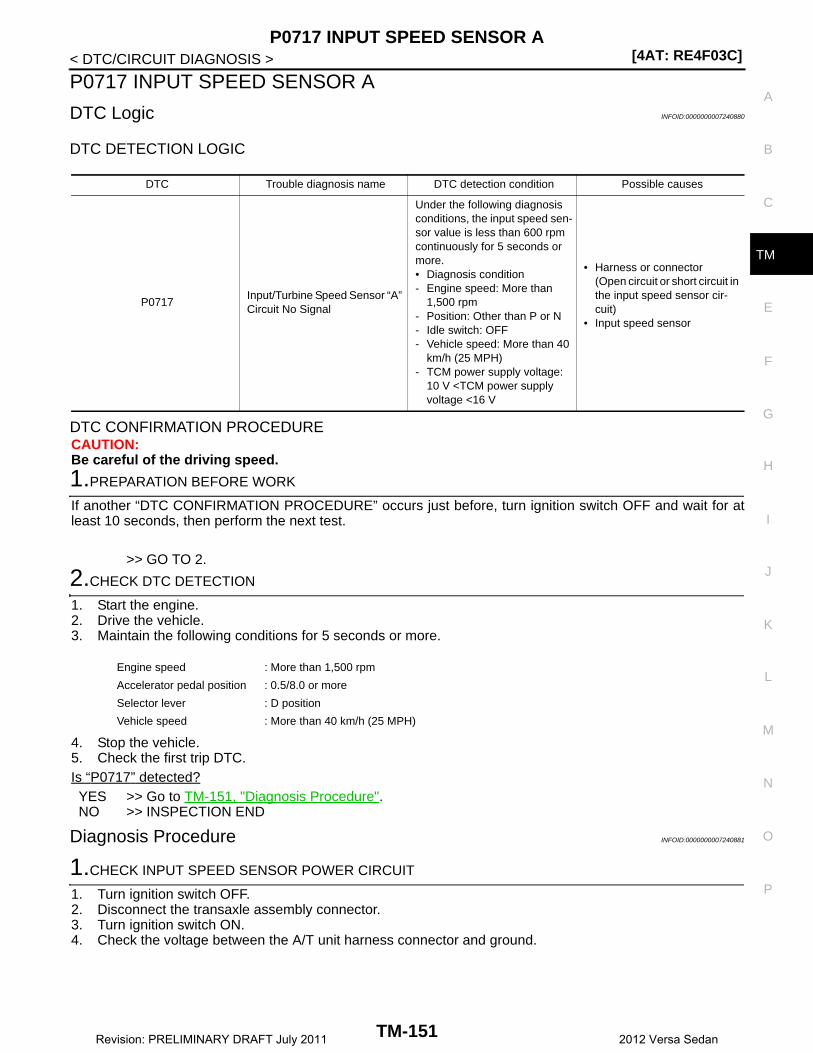
P0717 INPUT SPEED SENSOR A[4AT: RE4F03C]
C
E
F
G
H
I
J
K
L
M
A
B
M
N
O
P
< DTC/CIRCUIT DIAGNOSIS >
T
P0717 INPUT SPEED SENSOR A
DTC Logic INFOID:0000000007240880
DTC DETECTION LOGIC
DTC CONFIRMATION PROCEDURECAUTION:Be careful of the driving speed.
1.PREPARATION BEFORE WORK
If another “DTC CONFIRMATION PROCEDURE” occurs just before, turn ignition switch OFF and wait for atleast 10 seconds, then perform the next test.
>> GO TO 2.
2.CHECK DTC DETECTION
1. Start the engine.2. Drive the vehicle.3. Maintain the following conditions for 5 seconds or more.
4. Stop the vehicle.5. Check the first trip DTC.Is “P0717” detected?YES >> Go to TM-151, "Diagnosis Procedure".NO >> INSPECTION END
Diagnosis Procedure INFOID:0000000007240881
1.CHECK INPUT SPEED SENSOR POWER CIRCUIT
1. Turn ignition switch OFF.2. Disconnect the transaxle assembly connector.3. Turn ignition switch ON.4. Check the voltage between the A/T unit harness connector and ground.
DTC Trouble diagnosis name DTC detection condition Possible causes
P0717Input/Turbine Speed Sensor “A” Circuit No Signal
Under the following diagnosis conditions, the input speed sen-sor value is less than 600 rpm continuously for 5 seconds or more.• Diagnosis condition- Engine speed: More than
1,500 rpm- Position: Other than P or N- Idle switch: OFF- Vehicle speed: More than 40
km/h (25 MPH)- TCM power supply voltage:
10 V <TCM power supply voltage <16 V
• Harness or connector(Open circuit or short circuit in the input speed sensor cir-cuit)
• Input speed sensor
Engine speed : More than 1,500 rpm
Accelerator pedal position : 0.5/8.0 or more
Selector lever : D position
Vehicle speed : More than 40 km/h (25 MPH)
TM-151Revision: PRELIMINARY DRAFT July 2011 2012 Versa Sedan

[4AT: RE4F03C]P0717 INPUT SPEED SENSOR A
< DTC/CIRCUIT DIAGNOSIS >
Is the check result normal?YES >> GO TO 2.NO >> Check the TCM power supply. Refer to TM-211, "Diagnosis Procedure".
2.CHECK INPUT SPEED SENSOR GROUND CIRCUIT
1. Turn ignition switch OFF.2. Check the continuity between the A/T unit harness connector and ground.
Is the check result normal?YES >> GO TO 3.NO >> Check or repair the malfunction items.
3.CHECK INPUT SPEED SENSOR SIGNAL CIRCUIT
1. Disconnect the TCM connector.2. Check the continuity between the TCM harness connector and the A/T unit harness connector.
Is the check result normal?YES >> GO TO 4.NO >> Check or repair the malfunction items.
4.CHECK INPUT SPEED SENSOR TCM CIRCUIT (CHECK 3)
Check the continuity between TCM harness connector and ground.
Is the check result normal?YES >> GO TO 5.NO >> Check or repair the malfunction items.
5.CHECK TCM INPUT SIGNALS
1. Connect all of the disconnected connectors.2. Lift the vehicle.3. Start the engine.4. Check the frequency of the input speed sensor.
A/T unit harness connectorGround Voltage
Connector Terminal
F46 14 Ground Approx. 5 V
A/T unit harness connectorGround Continuity
Connector Terminal
F46 16 Ground Exists
TCM harness connector A/T unit harness connectorContinuity
Connector Terminal Connector Terminal
F44 35 F46 10 Exists
TCM harness connectorGround Continuity
Connector Terminal
F44 35 Ground Does not exist
TM-152Revision: PRELIMINARY DRAFT July 2011 2012 Versa Sedan

P0717 INPUT SPEED SENSOR A[4AT: RE4F03C]
C
E
F
G
H
I
J
K
L
M
A
B
M
N
O
P
< DTC/CIRCUIT DIAGNOSIS >
TIs the check result normal?YES >> Perform a simulation test to judge the cause of the malfunction. Refer to XX-XX, "*****". NO >> Replace the transaxle assembly. Refer to TM-242, "Removal and Installation".
TCM connectorGround Condition Standard
Connector Terminal
F44 35 Ground
• Selector lever: 1 position
• While driving at 20km/h (12 MPH)
Approx. 880 Hz
JSDIA1906GB
TM-153Revision: PRELIMINARY DRAFT July 2011 2012 Versa Sedan

[4AT: RE4F03C]P0720 OUTPUT SPEED SENSOR
< DTC/CIRCUIT DIAGNOSIS >
P0720 OUTPUT SPEED SENSOR
DTC Logic INFOID:0000000007240882
DTC DETECTION LOGIC
DTC CONFIRMATION PROCEDURECAUTION:Be careful of the driving speed.
1.PREPARATION BEFORE WORK
If another “DTC CONFIRMATION PROCEDURE” occurs just before, turn ignition switch OFF and wait for atleast 10 seconds, then perform the next test.
>> GO TO 2.
2.CHECK DTC DETECTION
1. Start the engine.2. Maintain the following conditions for 10 seconds or more.
3. Stop the vehicle.4. Check the first trip DTC.Is “P0720” detected?YES >> Go to TM-154, "Diagnosis Procedure".NO >> INSPECTION END
Diagnosis Procedure INFOID:0000000007240883
1.CHECK OUTPUT SPEED SENSOR POWER CIRCUIT (CHECK 1)
1. Turn ignition switch OFF.2. Disconnect the output speed sensor connector. 3. Turn the ignition switch ON.4. Check the voltage between the output speed sensor harness connector and ground.
Is the check result normal?YES >> GO TO 2.NO >> GO TO 6.
DTC Trouble diagnosis name DTC detection condition Possible causes
P0720 Output Speed Sensor Circuit
Under the following diagnosis conditions, the output speed sensor value is less than 100 rpm continuously for 5 seconds or more.• Diagnosis condition- Selector lever: Shift to a posi-
tion other than P or N.- Throttle position: More than
0.0/8.0- Input speed: More than 1,000
rpm
• Harness or connector(Open circuit or short circuit in the output speed sensor cir-cuit)
• Output speed sensor
Selector lever : N position ⇒ D position
Throttle position : 0.5/8.0 or more
Engine speed : More than 1,500 rpm
Output speed sensor harness connectorGround Voltage
Connector Terminal
F41 3 Ground 10 – 16V
TM-154Revision: PRELIMINARY DRAFT July 2011 2012 Versa Sedan

P0720 OUTPUT SPEED SENSOR[4AT: RE4F03C]
C
E
F
G
H
I
J
K
L
M
A
B
M
N
O
P
< DTC/CIRCUIT DIAGNOSIS >
T
2.CHECK OUTPUT SPEED SENSOR GROUND CIRCUIT
1. Turn ignition switch OFF.2. Check the continuity between the output speed sensor harness connector and ground.
Is the check result normal?YES >> GO TO 3.NO >> Check or repair the malfunction items.
3.CHECK OUTPUT SPEED SENSOR SIGNAL CIRCUIT (CHECK 1)
1. Disconnect the TCM connector.2. Check the continuity between the output speed sensor harness connector and the TCM harness connec-
tor.
Is the check result normal?YES >> GO TO 4.NO >> Check or repair the malfunction items.
4.CHECK OUTPUT SPEED SENSOR SIGNAL CIRCUIT (CHECK 2)
Check the continuity between the output speed sensor harness connector and ground.
Is the check result normal?YES >> GO TO 5.NO >> Check or repair the malfunction items.
5.CHECK OUTPUT SPEED SENSOR SIGNAL
1. Connect all of the disconnected connectors.2. Lift the vehicle.3. Start the engine.4. Check the frequency of the output speed sensor.
Is the check result normal?YES >> Perform a simulation test to judge the cause of the malfunction. Refer to XX-XX, "*****". NO >> Replace the output speed sensor. Refer to TM-237, "Removal and Installation".
Output speed sensor harness connectorGround Continuity
Connector Terminal
F41 1 Ground Exists
Output speed sensor harness connector TCM harness connectorContinuity
Connector Terminal Connector Terminal
F41 2 F18 24 Exists
Output speed sensor harness connectorGround Continuity
Connector Terminal
F41 2 Ground Does not exist
TCM connectorGround Condition Standard
Connector Terminal
F44 24 Ground
• Selector lever: 1 position
• While driving at 20 km/h (12 MPH)
Approx. 640 Hz
JSDIA1904GB
TM-155Revision: PRELIMINARY DRAFT July 2011 2012 Versa Sedan
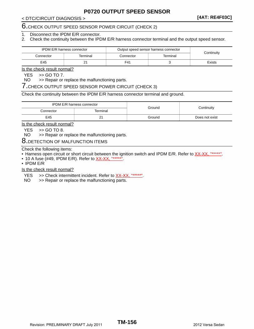
[4AT: RE4F03C]P0720 OUTPUT SPEED SENSOR
< DTC/CIRCUIT DIAGNOSIS >
6.CHECK OUTPUT SPEED SENSOR POWER CIRCUIT (CHECK 2)
1. Disconnect the IPDM E/R connector.2. Check the continuity between the IPDM E/R harness connector terminal and the output speed sensor.
Is the check result normal?YES >> GO TO 7.NO >> Repair or replace the malfunctioning parts.
7.CHECK OUTPUT SPEED SENSOR POWER CIRCUIT (CHECK 3)
Check the continuity between the IPDM E/R harness connector terminal and ground.
Is the check result normal?YES >> GO TO 8.NO >> Repair or replace the malfunctioning parts.
8.DETECTION OF MALFUNCTION ITEMS
Check the following items:• Harness open circuit or short circuit between the ignition switch and IPDM E/R. Refer to XX-XX, "*****".• 10 A fuse (#49, IPDM E/R). Refer to XX-XX, "*****".• IPDM E/RIs the check result normal?YES >> Check intermittent incident. Refer to XX-XX, "*****".NO >> Repair or replace the malfunctioning parts.
IPDM E/R harness connector Output speed sensor harness connectorContinuity
Connector Terminal Connector Terminal
E45 21 F41 3 Exists
IPDM E/R harness connectorGround Continuity
Connector Terminal
E45 21 Ground Does not exist
TM-156Revision: PRELIMINARY DRAFT July 2011 2012 Versa Sedan

P0731 1GR INCORRECT RATIO[4AT: RE4F03C]
C
E
F
G
H
I
J
K
L
M
A
B
M
N
O
P
< DTC/CIRCUIT DIAGNOSIS >
T
P0731 1GR INCORRECT RATIO
Description INFOID:0000000007240884
This malfunction is detected when the A/T does not shift into 1GR position as instructed by TCM. This is notonly caused by electrical malfunction (circuits open or shorted) but by mechanical malfunction such as controlvalve sticking, improper solenoid valve operation, etc.
DTC Logic INFOID:0000000007240885
DTC DETECTION LOGIC
DTC CONFIRMATION PROCEDURECAUTION:• “TM-159, "Diagnosis Procedure"” must be performed before starting “DTC CONFIRMATION PROCE-
DURE”.• Never perform “DTC CONFIRMATION PROCEDURE” before completing the repair, which may cause
secondary malfunction.• Always drive vehicle at a safe speed.
1.PREPARATION BEFORE WORK
If another “DTC CONFIRMATION PROCEDURE” occurs just before, turn ignition switch OFF and wait for atleast 10 seconds, then perform the next test.
>> GO TO 2.
2.CHECK DTC DETECTION (CHECK 1)
With CONSULT
DTC Trouble diagnosis name DTC detection condition Possible causes
P0731 Gear 1 Incorrect Ratio
Under the following diagnosis conditions, the gear ratio is 1.531 –1.593 (2GR ratio), 0.980 –1.020 (3GR ratio), or 0.683 – 0.711 (4GR ratio) continuously for 2 seconds or more.• Diagnosis condition- Shifting is not in progress.- Input speed: 300 rpm or more- Output speed: 300 rpm or
more- Engine speed: (Input speed –
50 rpm) or more- Selector lever: D position- Gear: 1GR- Throttle position: 3/8 or more
• Clutches and brakes• Hydraulic circuit• Control valve assembly
Under the following diagnosis conditions, the gear ratio is 1.531 –1.593 (2GR ratio), 0.980 –1.020 (3GR ratio), or 0.683 – 0.711 (4GR ratio) continuously for 2 seconds or more.• Diagnosis condition- Shifting is not in progress.- Input speed: 300 rpm or more- Output speed: 300 rpm or
more- Engine speed: (Input speed –
50 rpm) or more- Selector lever: 1 position- Throttle position: 0.7/8 or
more
• Clutches and brakes• Hydraulic circuit• Control valve assembly
TM-157Revision: PRELIMINARY DRAFT July 2011 2012 Versa Sedan
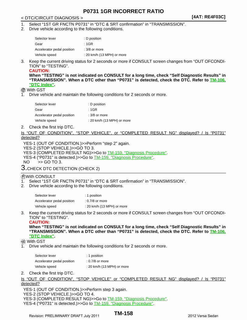
[4AT: RE4F03C]P0731 1GR INCORRECT RATIO
< DTC/CIRCUIT DIAGNOSIS >1. Select “1ST GR FNCTN P0731” in “DTC & SRT confirmation” in “TRANSMISSION”.2. Drive vehicle according to the following conditions.
3. Keep the current driving status for 2 seconds or more if CONSULT screen changes from “OUT OFCONDI-TION” to “TESTING”.CAUTION:When “TESTING” is not indicated on CONSULT for a long time, check “Self Diagnostic Results” in“TRANSMISSION”. When a DTC other than “P0731” is detected, check the DTC. Refer to TM-106,"DTC Index".
With GST1. Drive vehicle and maintain the following conditions for 2 seconds or more.
2. Check the first trip DTC.Is “OUT OF CONDITION”, “STOP VEHICLE”, or “COMPLETED RESULT NG” displayed? / Is “P0731”detected?YES-1 (OUT OF CONDITION.)>>Perform “step 2” again.YES-2 (STOP VEHICLE.)>>GO TO 3.YES-3 (COMPLETED RESULT NG)>>Go to TM-159, "Diagnosis Procedure".YES-4 (“P0731” is detected.)>>Go to TM-159, "Diagnosis Procedure".NO >> GO TO 3.
3.CHECK DTC DETECTION (CHECK 2)
With CONSULT1. Select “1ST GR FNCTN P0731” in “DTC & SRT confirmation” in “TRANSMISSION”.2. Drive vehicle according to the following conditions.
3. Keep the current driving status for 2 seconds or more if CONSULT screen changes from “OUT OFCONDI-TION” to “TESTING”.CAUTION:When “TESTING” is not indicated on CONSULT for a long time, check “Self Diagnostic Results” in“TRANSMISSION”. When a DTC other than “P0731” is detected, check the DTC. Refer to TM-106,"DTC Index".
With GST1. Drive vehicle and maintain the following conditions for 2 seconds or more.
2. Check the first trip DTC.Is “OUT OF CONDITION”, “STOP VEHICLE” or “COMPLETED RESULT NG” displayed? / Is “P0731”detected?YES-1 (OUT OF CONDITION.)>>Perform step 3 again.YES-2 (STOP VEHICLE.)>>GO TO 4.YES-3 (COMPLETED RESULT NG)>>Go to TM-159, "Diagnosis Procedure".YES-4 (“P0731” is detected.)>>Go to TM-159, "Diagnosis Procedure".
Selector lever : D position
Gear : 1GR
Accelerator pedal position : 3/8 or more
Vehicle speed : 20 km/h (13 MPH) or more
Selector lever : D position
Gear : 1GR
Accelerator pedal position : 3/8 or more
Vehicle speed : 20 km/h (13 MPH) or more
Selector lever : 1 position
Accelerator pedal position : 0.7/8 or more
Vehicle speed : 20 km/h (13 MPH) or more
Selector lever : 1 position
Accelerator pedal position : 0.7/8 or more
Vehicle speed : 20 km/h (13 MPH) or more
TM-158Revision: PRELIMINARY DRAFT July 2011 2012 Versa Sedan
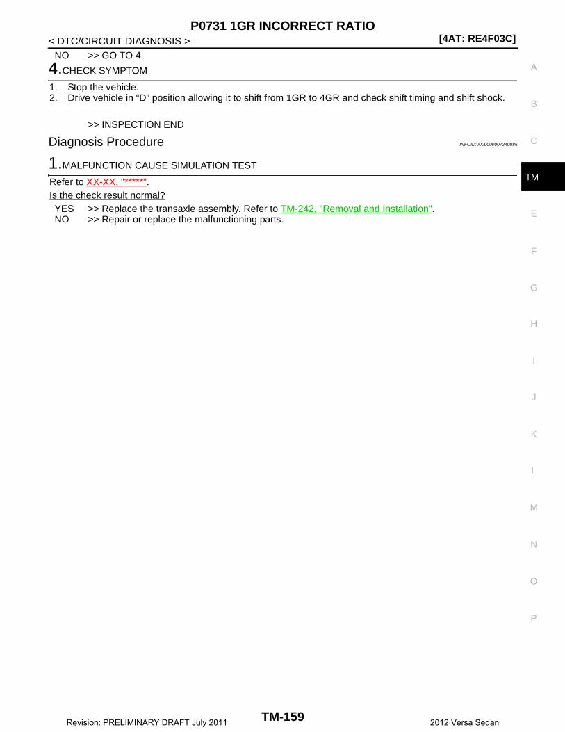
P0731 1GR INCORRECT RATIO[4AT: RE4F03C]
C
E
F
G
H
I
J
K
L
M
A
B
M
N
O
P
< DTC/CIRCUIT DIAGNOSIS >
T
NO >> GO TO 4.
4.CHECK SYMPTOM
1. Stop the vehicle.2. Drive vehicle in “D” position allowing it to shift from 1GR to 4GR and check shift timing and shift shock.
>> INSPECTION END
Diagnosis Procedure INFOID:0000000007240886
1.MALFUNCTION CAUSE SIMULATION TEST
Refer to XX-XX, "*****". Is the check result normal?YES >> Replace the transaxle assembly. Refer to TM-242, "Removal and Installation".NO >> Repair or replace the malfunctioning parts.
TM-159Revision: PRELIMINARY DRAFT July 2011 2012 Versa Sedan

[4AT: RE4F03C]P0732 2GR INCORRECT RATIO
< DTC/CIRCUIT DIAGNOSIS >
P0732 2GR INCORRECT RATIO
Description INFOID:0000000007240887
This malfunction is detected when the A/T does not shift into 2GR position as instructed by TCM. This is notonly caused by electrical malfunction (circuits open or shorted) but by mechanical malfunction such as controlvalve sticking, improper solenoid valve operation, etc.
DTC Logic INFOID:0000000007240888
DTC DETECTION LOGIC
DTC CONFIRMATION PROCEDURECAUTION:• “TM-161, "Diagnosis Procedure"” must be performed before starting “DTC CONFIRMATION PROCE-
DURE”.• Never perform “DTC CONFIRMATION PROCEDURE” before completing the repair, which may cause
secondary malfunction.• Always drive vehicle at a safe speed.
1.PREPARATION BEFORE WORK
If another “DTC CONFIRMATION PROCEDURE” occurs just before, turn ignition switch OFF and wait for atleast 10 seconds, then perform the next test.
>> GO TO 2.
2.CHECK DTC DETECTION
With CONSULT1. Select “2ND GR FNCTN P0732” in “DTC & SRT confirmation” in “TRANSMISSION”.2. Drive vehicle according to the following conditions.
3. Keep the current driving status for 2 seconds or more if CONSULT screen changes from “OUT OFCONDI-TION” to “TESTING”.CAUTION:When “TESTING” is not indicated on CONSULT for a long time, check “Self Diagnostic Results” in“TRANSMISSION”. When a DTC other than “P0732” is detected, check the DTC. Refer to TM-106,"DTC Index".
DTC Trouble diagnosis name DTC detection condition Possible causes
P0732 Gear 2 Incorrect Ratio
Under the following diagnosis conditions, the gear ratio is 2.804 – 2.918 (1GR ratio), 0.980 – 1.020 (3GR ratio), or 0.683 – 0.711 (4GR ratio) con-tinuously for 2 seconds or more.• Diagnosis condition- Shifting is not in progress.- Input speed: 300 rpm or more- Output speed: 300 rpm or
more- Engine speed: (Input speed –
50 rpm) or more- Selector lever: 2 position- Gear: 2GR- Throttle position: 0.7/8.0 or
more
• Clutches and brakes• Hydraulic circuit• Control valve assembly
Selector lever : 2 position
Gear : 2GR
Accelerator pedal position : 0.7/8 or more
Vehicle speed : 20 km/h (13 MPH) or more
TM-160Revision: PRELIMINARY DRAFT July 2011 2012 Versa Sedan

P0732 2GR INCORRECT RATIO[4AT: RE4F03C]
C
E
F
G
H
I
J
K
L
M
A
B
M
N
O
P
< DTC/CIRCUIT DIAGNOSIS >
T
With GST1. Drive vehicle and maintain the following conditions for 2 seconds or more.
2. Check the first trip DTC.Is “OUT OF CONDITION”, “STOP VEHICLE”, or “COMPLETED RESULT NG” displayed? / Is “P0732”detected?YES-1 (OUT OF CONDITION.)>>Perform “step 2” again.YES-2 (STOP VEHICLE.)>>GO TO 3.YES-3 (COMPLETED RESULT NG)>>Go to TM-161, "Diagnosis Procedure".YES-4 (“P0732” is detected.)>>Go to TM-161, "Diagnosis Procedure".NO >> GO TO 3.
3.CHECK SYMPTOM
1. Stop the vehicle.2. Drive vehicle in “D” position allowing it to shift from 1GR to 4GR and check shift timing and shift shock.
>> INSPECTION END
Diagnosis Procedure INFOID:0000000007240889
1.MALFUNCTION CAUSE SIMULATION TEST
Refer to XX-XX, "*****". Is the check result normal?YES >> Replace the transaxle assembly. Refer to TM-242, "Removal and Installation".NO >> Repair or replace the malfunctioning parts.
Selector lever : 2 position
Gear : 2GR
Accelerator pedal position : 0.7/8 or more
Vehicle speed : 20 km/h (13 MPH) or more
TM-161Revision: PRELIMINARY DRAFT July 2011 2012 Versa Sedan
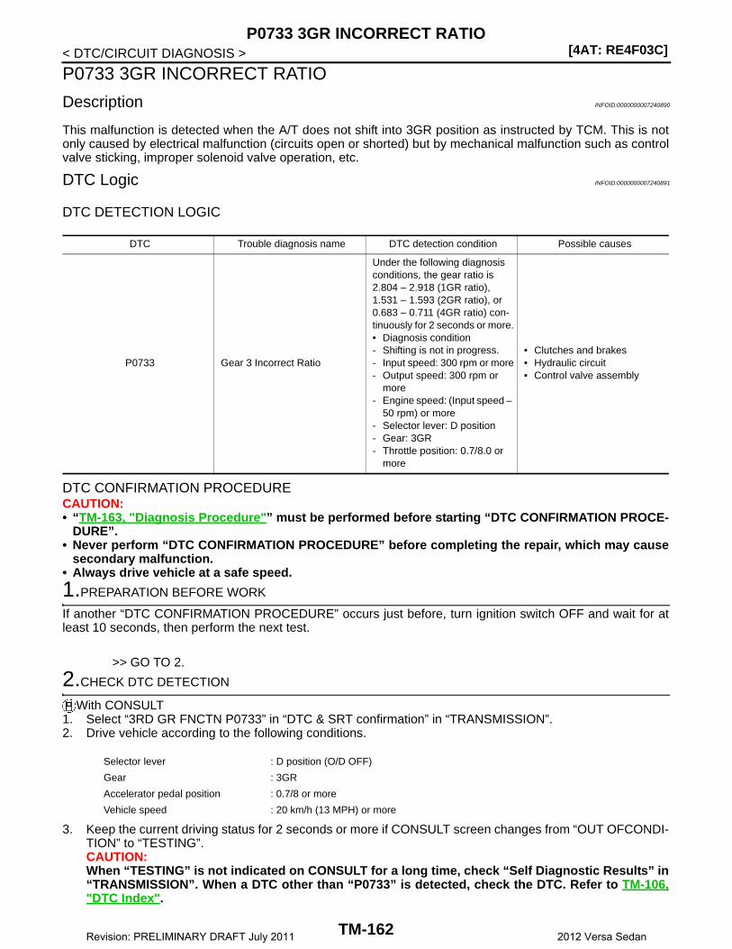
[4AT: RE4F03C]P0733 3GR INCORRECT RATIO
< DTC/CIRCUIT DIAGNOSIS >
P0733 3GR INCORRECT RATIO
Description INFOID:0000000007240890
This malfunction is detected when the A/T does not shift into 3GR position as instructed by TCM. This is notonly caused by electrical malfunction (circuits open or shorted) but by mechanical malfunction such as controlvalve sticking, improper solenoid valve operation, etc.
DTC Logic INFOID:0000000007240891
DTC DETECTION LOGIC
DTC CONFIRMATION PROCEDURECAUTION:• “TM-163, "Diagnosis Procedure"” must be performed before starting “DTC CONFIRMATION PROCE-
DURE”.• Never perform “DTC CONFIRMATION PROCEDURE” before completing the repair, which may cause
secondary malfunction.• Always drive vehicle at a safe speed.
1.PREPARATION BEFORE WORK
If another “DTC CONFIRMATION PROCEDURE” occurs just before, turn ignition switch OFF and wait for atleast 10 seconds, then perform the next test.
>> GO TO 2.
2.CHECK DTC DETECTION
With CONSULT1. Select “3RD GR FNCTN P0733” in “DTC & SRT confirmation” in “TRANSMISSION”.2. Drive vehicle according to the following conditions.
3. Keep the current driving status for 2 seconds or more if CONSULT screen changes from “OUT OFCONDI-TION” to “TESTING”.CAUTION:When “TESTING” is not indicated on CONSULT for a long time, check “Self Diagnostic Results” in“TRANSMISSION”. When a DTC other than “P0733” is detected, check the DTC. Refer to TM-106,"DTC Index".
DTC Trouble diagnosis name DTC detection condition Possible causes
P0733 Gear 3 Incorrect Ratio
Under the following diagnosis conditions, the gear ratio is 2.804 – 2.918 (1GR ratio), 1.531 – 1.593 (2GR ratio), or 0.683 – 0.711 (4GR ratio) con-tinuously for 2 seconds or more.• Diagnosis condition- Shifting is not in progress.- Input speed: 300 rpm or more- Output speed: 300 rpm or
more- Engine speed: (Input speed –
50 rpm) or more- Selector lever: D position- Gear: 3GR- Throttle position: 0.7/8.0 or
more
• Clutches and brakes• Hydraulic circuit• Control valve assembly
Selector lever : D position (O/D OFF)
Gear : 3GR
Accelerator pedal position : 0.7/8 or more
Vehicle speed : 20 km/h (13 MPH) or more
TM-162Revision: PRELIMINARY DRAFT July 2011 2012 Versa Sedan
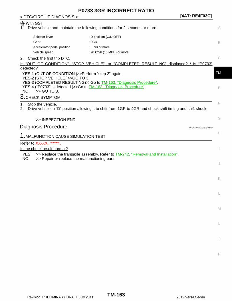
P0733 3GR INCORRECT RATIO[4AT: RE4F03C]
C
E
F
G
H
I
J
K
L
M
A
B
M
N
O
P
< DTC/CIRCUIT DIAGNOSIS >
T
With GST1. Drive vehicle and maintain the following conditions for 2 seconds or more.
2. Check the first trip DTC.Is “OUT OF CONDITION”, “STOP VEHICLE”, or “COMPLETED RESULT NG” displayed? / Is “P0733”detected?YES-1 (OUT OF CONDITION.)>>Perform “step 2” again.YES-2 (STOP VEHICLE.)>>GO TO 3.YES-3 (COMPLETED RESULT NG)>>Go to TM-163, "Diagnosis Procedure".YES-4 (“P0733” is detected.)>>Go to TM-163, "Diagnosis Procedure".NO >> GO TO 3.
3.CHECK SYMPTOM
1. Stop the vehicle.2. Drive vehicle in “D” position allowing it to shift from 1GR to 4GR and check shift timing and shift shock.
>> INSPECTION END
Diagnosis Procedure INFOID:0000000007240892
1.MALFUNCTION CAUSE SIMULATION TEST
Refer to XX-XX, "*****". Is the check result normal?YES >> Replace the transaxle assembly. Refer to TM-242, "Removal and Installation".NO >> Repair or replace the malfunctioning parts.
Selector lever : D position (O/D OFF)
Gear : 3GR
Accelerator pedal position : 0.7/8 or more
Vehicle speed : 20 km/h (13 MPH) or more
TM-163Revision: PRELIMINARY DRAFT July 2011 2012 Versa Sedan

[4AT: RE4F03C]P0734 4GR INCORRECT RATIO
< DTC/CIRCUIT DIAGNOSIS >
P0734 4GR INCORRECT RATIO
Description INFOID:0000000007240893
This malfunction is detected when the A/T does not shift into 4GR position as instructed by TCM. This is notonly caused by electrical malfunction (circuits open or shorted) but by mechanical malfunction such as controlvalve sticking, improper solenoid valve operation, etc.
DTC Logic INFOID:0000000007240894
DTC DETECTION LOGIC
DTC CONFIRMATION PROCEDURECAUTION:• “TM-165, "Diagnosis Procedure"” must be performed before starting “DTC CONFIRMATION PROCE-
DURE”.• Never perform “DTC CONFIRMATION PROCEDURE” before completing the repair, which may cause
secondary malfunction.• Always drive vehicle at a safe speed.
1.PREPARATION BEFORE WORK
If another “DTC CONFIRMATION PROCEDURE” occurs just before, turn ignition switch OFF and wait for atleast 10 seconds, then perform the next test.
>> GO TO 2.
2.CHECK DTC DETECTION
With CONSULT1. Select “4TH GR FNCTN P0734” in “DTC & SRT confirmation” in “TRANSMISSION”.2. Drive vehicle according to the following conditions.
3. Keep the current driving status for 2 seconds or more if CONSULT screen changes from “OUT OFCONDI-TION” to “TESTING”.CAUTION:When “TESTING” is not indicated on CONSULT for a long time, check “Self Diagnostic Results” in“TRANSMISSION”. When a DTC other than “P0734” is detected, check the DTC. Refer to TM-106,"DTC Index".
DTC Trouble diagnosis name DTC detection condition Possible causes
P0734 Gear 4 Incorrect Ratio
Under the following diagnosis conditions, the gear ratio is 2.804 − 2.918 (1GR ratio), 1.531 − 1.593 (2GR ratio), or 0.980 − 1.020 (3GR ratio) con-tinuously for 2 seconds or more.• Diagnosis condition- Shifting is not in progress.- Input speed: 300 rpm or more- Output speed: 300 rpm or
more- Engine speed: (Input speed –
50 rpm) or more- Selector lever: D position- Gear: 4GR- Throttle position: 0.7/8.0 or
more
• Clutches and brakes• Hydraulic circuit• Control valve assembly
Selector lever : D position
Gear : 4GR
Accelerator pedal position : 0.7/8 or more
Vehicle speed : 20 km/h (13 MPH) or more
TM-164Revision: PRELIMINARY DRAFT July 2011 2012 Versa Sedan
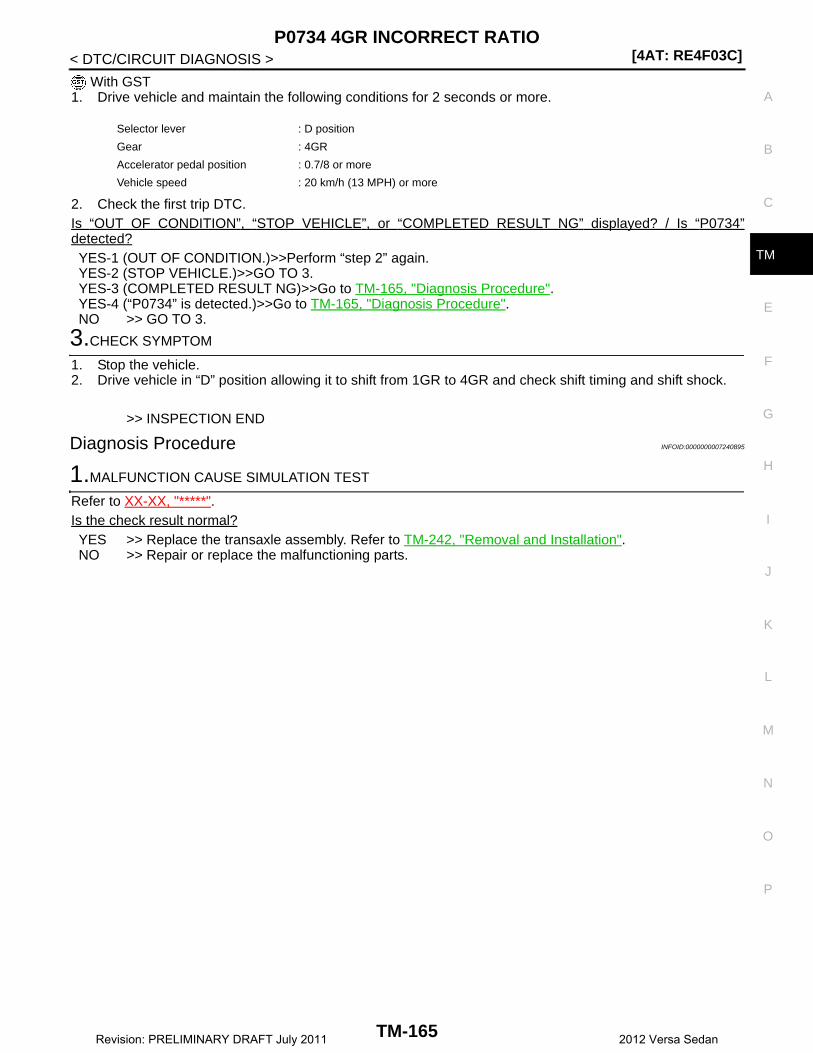
P0734 4GR INCORRECT RATIO[4AT: RE4F03C]
C
E
F
G
H
I
J
K
L
M
A
B
M
N
O
P
< DTC/CIRCUIT DIAGNOSIS >
T
With GST1. Drive vehicle and maintain the following conditions for 2 seconds or more.
2. Check the first trip DTC.Is “OUT OF CONDITION”, “STOP VEHICLE”, or “COMPLETED RESULT NG” displayed? / Is “P0734”detected?YES-1 (OUT OF CONDITION.)>>Perform “step 2” again.YES-2 (STOP VEHICLE.)>>GO TO 3.YES-3 (COMPLETED RESULT NG)>>Go to TM-165, "Diagnosis Procedure".YES-4 (“P0734” is detected.)>>Go to TM-165, "Diagnosis Procedure".NO >> GO TO 3.
3.CHECK SYMPTOM
1. Stop the vehicle.2. Drive vehicle in “D” position allowing it to shift from 1GR to 4GR and check shift timing and shift shock.
>> INSPECTION END
Diagnosis Procedure INFOID:0000000007240895
1.MALFUNCTION CAUSE SIMULATION TEST
Refer to XX-XX, "*****". Is the check result normal?YES >> Replace the transaxle assembly. Refer to TM-242, "Removal and Installation".NO >> Repair or replace the malfunctioning parts.
Selector lever : D position
Gear : 4GR
Accelerator pedal position : 0.7/8 or more
Vehicle speed : 20 km/h (13 MPH) or more
TM-165Revision: PRELIMINARY DRAFT July 2011 2012 Versa Sedan
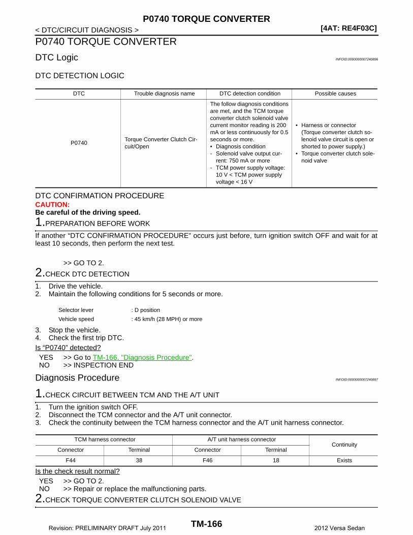
[4AT: RE4F03C]P0740 TORQUE CONVERTER
< DTC/CIRCUIT DIAGNOSIS >
P0740 TORQUE CONVERTER
DTC Logic INFOID:0000000007240896
DTC DETECTION LOGIC
DTC CONFIRMATION PROCEDURECAUTION:Be careful of the driving speed.
1.PREPARATION BEFORE WORK
If another “DTC CONFIRMATION PROCEDURE” occurs just before, turn ignition switch OFF and wait for atleast 10 seconds, then perform the next test.
>> GO TO 2.
2.CHECK DTC DETECTION
1. Drive the vehicle.2. Maintain the following conditions for 5 seconds or more.
3. Stop the vehicle.4. Check the first trip DTC.Is “P0740” detected?YES >> Go to TM-166, "Diagnosis Procedure".NO >> INSPECTION END
Diagnosis Procedure INFOID:0000000007240897
1.CHECK CIRCUIT BETWEEN TCM AND THE A/T UNIT
1. Turn the ignition switch OFF.2. Disconnect the TCM connector and the A/T unit connector.3. Check the continuity between the TCM harness connector and the A/T unit harness connector.
Is the check result normal?YES >> GO TO 2.NO >> Repair or replace the malfunctioning parts.
2.CHECK TORQUE CONVERTER CLUTCH SOLENOID VALVE
DTC Trouble diagnosis name DTC detection condition Possible causes
P0740Torque Converter Clutch Cir-cuit/Open
The follow diagnosis conditions are met, and the TCM torque converter clutch solenoid valve current monitor reading is 200 mA or less continuously for 0.5 seconds or more.• Diagnosis condition- Solenoid valve output cur-
rent: 750 mA or more- TCM power supply voltage:
10 V < TCM power supply voltage < 16 V
• Harness or connector(Torque converter clutch so-lenoid valve circuit is open or shorted to power supply.)
• Torque converter clutch sole-noid valve
Selector lever : D position
Vehicle speed : 45 km/h (28 MPH) or more
TCM harness connector A/T unit harness connectorContinuity
Connector Terminal Connector Terminal
F44 38 F46 18 Exists
TM-166Revision: PRELIMINARY DRAFT July 2011 2012 Versa Sedan

P0740 TORQUE CONVERTER[4AT: RE4F03C]
C
E
F
G
H
I
J
K
L
M
A
B
M
N
O
P
< DTC/CIRCUIT DIAGNOSIS >
T
Check the torque converter clutch solenoid valve. Refer to TM-167, "Component Inspection (Torque ConverterClutch Solenoid Valve)".Is the check result normal?YES >> Check intermittent incident. Refer to XX-XX, "*****".NO >> Repair or replace the malfunctioning parts.
Component Inspection (Torque Converter Clutch Solenoid Valve) INFOID:0000000007240898
1.CHECK TORQUE CONVERTER CLUTCH SOLENOID VALVE
Check the resistance between the A/T unit connector terminal and ground.
Is the check result normal?YES >> INSPECTION ENDNO >> There is a malfunction of the torque converter clutch solenoid valve. Replace the transaxle
assembly. Refer to TM-242, "Removal and Installation".
A/T unit connectorGround Condition Resistance
Terminal
18 Ground
A/T fluid temperature: 20°C (68°F)
Approx. 6.1 Ω
A/T fluid temperature: 50°C (122°F)
Approx. 6.9 Ω
A/T fluid temperature: 80°C (176°F)
Approx. 7.7 Ω
TM-167Revision: PRELIMINARY DRAFT July 2011 2012 Versa Sedan
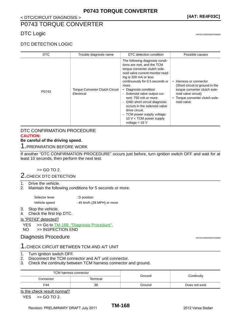
[4AT: RE4F03C]P0743 TORQUE CONVERTER
< DTC/CIRCUIT DIAGNOSIS >
P0743 TORQUE CONVERTER
DTC Logic INFOID:0000000007240899
DTC DETECTION LOGIC
DTC CONFIRMATION PROCEDURECAUTION:Be careful of the driving speed.
1.PREPARATION BEFORE WORK
If another “DTC CONFIRMATION PROCEDURE” occurs just before, turn ignition switch OFF and wait for atleast 10 seconds, then perform the next test.
>> GO TO 2.
2.CHECK DTC DETECTION
1. Drive the vehicle.2. Maintain the following conditions for 5 seconds or more.
3. Stop the vehicle.4. Check the first trip DTC.Is “P0743” detected?YES >> Go to TM-168, "Diagnosis Procedure".NO >> INSPECTION END
Diagnosis Procedure INFOID:0000000007240900
1.CHECK CIRCUIT BETWEEN TCM AND A/T UNIT
1. Turn ignition switch OFF.2. Disconnect the TCM connector and A/T unit connector.3. Check the continuity between TCM harness connector and ground.
Is the check result normal?YES >> GO TO 2.
DTC Trouble diagnosis name DTC detection condition Possible causes
P0743Torque Converter Clutch Circuit Electrical
The following diagnosis condi-tions are met, and the TCM torque converter clutch sole-noid valve current monitor read-ing is 200 mA or less continuously for 0.5 seconds or more.• Diagnosis condition- Solenoid valve output cur-
rent: 750 mA or more- GND short circuit diagnosis
occurs in the solenoid valve drive circuit.
- TCM power supply voltage: 10 V < TCM power supply voltage < 16 V
• Harness or connector(Short circuit to ground in the torque converter clutch sole-noid valve circuit)
• Torque converter clutch sole-noid valve
Selector lever : D position
Vehicle speed : 45 km/h (28 MPH) or more
TCM harness connectorGround Continuity
Connector Terminal
F44 38 Ground Does not exist
TM-168Revision: PRELIMINARY DRAFT July 2011 2012 Versa Sedan
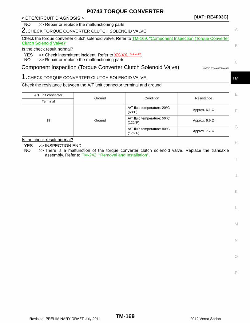
P0743 TORQUE CONVERTER[4AT: RE4F03C]
C
E
F
G
H
I
J
K
L
M
A
B
M
N
O
P
< DTC/CIRCUIT DIAGNOSIS >
T
NO >> Repair or replace the malfunctioning parts.
2.CHECK TORQUE CONVERTER CLUTCH SOLENOID VALVE
Check the torque converter clutch solenoid valve. Refer to TM-169, "Component Inspection (Torque ConverterClutch Solenoid Valve)".Is the check result normal?YES >> Check intermittent incident. Refer to XX-XX, "*****".NO >> Repair or replace the malfunctioning parts.
Component Inspection (Torque Converter Clutch Solenoid Valve) INFOID:0000000007240901
1.CHECK TORQUE CONVERTER CLUTCH SOLENOID VALVE
Check the resistance between the A/T unit connector terminal and ground.
Is the check result normal?YES >> INSPECTION ENDNO >> There is a malfunction of the torque converter clutch solenoid valve. Replace the transaxle
assembly. Refer to TM-242, "Removal and Installation".
A/T unit connectorGround Condition Resistance
Terminal
18 Ground
A/T fluid temperature: 20°C (68°F)
Approx. 6.1 Ω
A/T fluid temperature: 50°C (122°F)
Approx. 6.9 Ω
A/T fluid temperature: 80°C (176°F)
Approx. 7.7 Ω
TM-169Revision: PRELIMINARY DRAFT July 2011 2012 Versa Sedan

[4AT: RE4F03C]P0744 TORQUE CONVERTER
< DTC/CIRCUIT DIAGNOSIS >
P0744 TORQUE CONVERTER
Description INFOID:0000000007240902
This DTC is detected when the torque converter clutch solenoid valve is electrically normal but the torque con-verter clutch does not engage. This is not due to an electrical malfunction (circuit open or shorted), but isinstead due to a mechanical malfunction (sticking of the control valve, malfunction of the solenoid, etc.).
DTC Logic INFOID:0000000007240903
DTC DETECTION LOGIC
DTC REPRODUCTION PROCEDURECAUTION:Be careful of the driving speed.
1.PREPARATION BEFORE WORK
If another “DTC CONFIRMATION PROCEDURE” occurs just before, turn ignition switch OFF and wait for atleast 10 seconds, then perform the next test.
>> GO TO 2.
2.CHECK DTC DETECTION
1. Drive the vehicle.2. Maintain the following conditions for 35 seconds or more.
3. Stop the vehicle.4. Check the first trip DTC.Is “P0744” detected?YES >> Go to TM-170, "Diagnosis Procedure".NO >> Check intermittent incident. Refer to XX-XX, "*****".
Diagnosis Procedure INFOID:0000000007240904
1.CHECK LINE PRESSURE
Perform line pressure test. Refer to TM-126, "Inspection and Judgment".Is the check result normal?YES >> GO TO 2.NO >> Repair or replace the malfunction items.
2.CHECK TORQUE CONVERTER CLUTCH SOLENOID VALVE
1. Turn ignition switch OFF.2. Disconnect the A/T unit connector.3. Check the torque converter clutch solenoid valve. Refer to TM-171, "Component Inspection (Torque Con-
verter Clutch Solenoid Valve)".
DTC Trouble diagnosis name DTC detection condition Possible causes
P0744Torque Converter Clutch Circuit Intermittent
The following diagnosis condi-tions are met, and the torque converter slip speed is at or above a set value (40 rpm + Ve-hicle speed / 2) continuously for 30 seconds or more.• Diagnosis condition- Lock-up pressure difference:
More than Max. lock-up pres-sure difference × 0.95
• Torque converter clutch sole-noid valve
• Control valve assembly• Torque converter
Selector lever : D position
Vehicle speed : 45 km/h (28 MPH) or more
TM-170Revision: PRELIMINARY DRAFT July 2011 2012 Versa Sedan
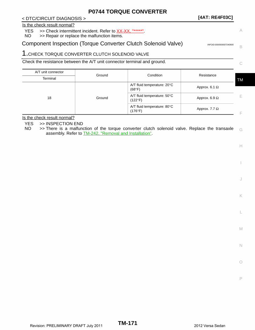
P0744 TORQUE CONVERTER[4AT: RE4F03C]
C
E
F
G
H
I
J
K
L
M
A
B
M
N
O
P
< DTC/CIRCUIT DIAGNOSIS >
T
Is the check result normal?YES >> Check intermittent incident. Refer to XX-XX, "*****".NO >> Repair or replace the malfunction items.
Component Inspection (Torque Converter Clutch Solenoid Valve) INFOID:0000000007240905
1.CHECK TORQUE CONVERTER CLUTCH SOLENOID VALVE
Check the resistance between the A/T unit connector terminal and ground.
Is the check result normal?YES >> INSPECTION ENDNO >> There is a malfunction of the torque converter clutch solenoid valve. Replace the transaxle
assembly. Refer to TM-242, "Removal and Installation".
A/T unit connectorGround Condition Resistance
Terminal
18 Ground
A/T fluid temperature: 20°C (68°F)
Approx. 6.1 Ω
A/T fluid temperature: 50°C (122°F)
Approx. 6.9 Ω
A/T fluid temperature: 80°C (176°F)
Approx. 7.7 Ω
TM-171Revision: PRELIMINARY DRAFT July 2011 2012 Versa Sedan

[4AT: RE4F03C]P0863 TCM COMMUNICATION
< DTC/CIRCUIT DIAGNOSIS >
P0863 TCM COMMUNICATION
Description INFOID:0000000007240906
CAN (Controller Area Network) is a serial communication line for real time application. It is an on-vehicle mul-tiplex communication line with high data communication speed and excellent malfunction detection ability.Many electronic control units are equipped onto a vehicle, and each control unit shares information and linkswith other control units during operation (not independent). In CAN communication, control units are con-nected with 2 communication lines (CAN-H and CAN-L) allowing a high rate of information transmission withless wiring. Each control unit transmits/receives data but selectively reads required data only.
DTC Logic INFOID:0000000007240907
DTC DETECTION LOGIC
DTC CONFIRMATION PROCEDURE
1.PREPARATION BEFORE WORK
If another “DTC CONFIRMATION PROCEDURE” occurs just before, turn the ignition switch OFF and wait forat least 10 seconds, then perform the next test.
>> GO TO 2.
2.CHECK DTC DETECTION
With CONSULT1. Start engine and wait for at least 10 seconds.2. Check DTC.Is “P0863” detected?YES >> Go to TM-172, "Diagnosis Procedure".NO >> Check intermittent incident. Refer to XX-XX, "*****".
Diagnosis Procedure INFOID:0000000007240908
1.CHECK CAN COMMUNICATION CIRCUIT
With CONSULT1. Start the engine.2. Check DTC.Is “P0863” indicated?YES >> Replace the TCM. Refer to TM-234, "Removal and Installation".NO >> Check intermittent incident. Refer to XX-XX, "*****".
DTC Trouble diagnosis name DTC detection condition Possible causes
P0863 TCM Communication CircuitWhen detecting error during the initial diagnosis of CAN control-ler to TCM.
Harness or connectors(CAN communication line is open or shorted.)
TM-172Revision: PRELIMINARY DRAFT July 2011 2012 Versa Sedan

P0962 PRESSURE CONTROL SOLENOID A[4AT: RE4F03C]
C
E
F
G
H
I
J
K
L
M
A
B
M
N
O
P
< DTC/CIRCUIT DIAGNOSIS >
T
P0962 PRESSURE CONTROL SOLENOID A
DTC Logic INFOID:0000000007240909
DTC DETECTION LOGIC
DTC CONFIRMATION PROCEDURE
1.PREPARATION BEFORE WORK
If another “DTC CONFIRMATION PROCEDURE” occurs just before, turn ignition switch OFF and wait for atleast 10 seconds, then perform the next test.
>> GO TO 2.
2.CHECK DTC DETECTION
1. Start the engine.2. Maintain the following conditions for 5 seconds or more.
3. Check the first trip DTC.Is “P0962” detected?YES >> Go to TM-173, "Diagnosis Procedure".NO >> INSPECTION END
Diagnosis Procedure INFOID:0000000007240910
1.CHECK CIRCUIT BETWEEN TCM AND A/T UNIT
1. Turn ignition switch OFF.2. Disconnect the TCM connector and A/T unit connector.3. Check the continuity between TCM harness connector and ground.
Is the check result normal?YES >> GO TO 2.NO >> Repair or replace the malfunctioning parts.
2.CHECK LINE PRESSURE SOLENOID VALVE
DTC Trouble diagnosis name DTC detection condition Possible causes
P0962Pressure Control Solenoid “A” Control Circuit Low
The following diagnosis condi-tions are met, and the current monitor reading of the TCM line pressure solenoid valve is 200 mA or less continuously for 0.5 seconds or more.• Diagnosis condition- Solenoid valve output cur-
rent: 750 mA or more- GND short circuit diagnosis
occurs in the solenoid valve drive circuit.
- TCM power supply voltage: 10 V < TCM power supply voltage < 16 V
• Harness or connector(Short circuit to ground in the line pressure solenoid valve circuit)
• Line pressure solenoid valve
Selector lever : N position
Engine speed : Idle speed
TCM harness connectorGround Continuity
Connector Terminal
F44 37 Ground Does not exist
TM-173Revision: PRELIMINARY DRAFT July 2011 2012 Versa Sedan
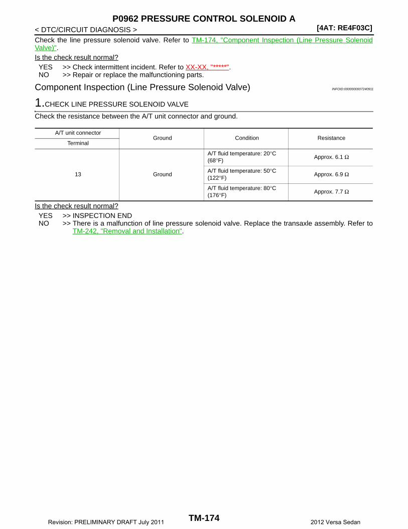
[4AT: RE4F03C]P0962 PRESSURE CONTROL SOLENOID A
< DTC/CIRCUIT DIAGNOSIS >Check the line pressure solenoid valve. Refer to TM-174, "Component Inspection (Line Pressure SolenoidValve)".Is the check result normal?YES >> Check intermittent incident. Refer to XX-XX, "*****".NO >> Repair or replace the malfunctioning parts.
Component Inspection (Line Pressure Solenoid Valve) INFOID:0000000007240911
1.CHECK LINE PRESSURE SOLENOID VALVE
Check the resistance between the A/T unit connector and ground.
Is the check result normal?YES >> INSPECTION ENDNO >> There is a malfunction of line pressure solenoid valve. Replace the transaxle assembly. Refer to
TM-242, "Removal and Installation".
A/T unit connectorGround Condition Resistance
Terminal
13 Ground
A/T fluid temperature: 20°C (68°F)
Approx. 6.1 Ω
A/T fluid temperature: 50°C (122°F)
Approx. 6.9 Ω
A/T fluid temperature: 80°C (176°F)
Approx. 7.7 Ω
TM-174Revision: PRELIMINARY DRAFT July 2011 2012 Versa Sedan
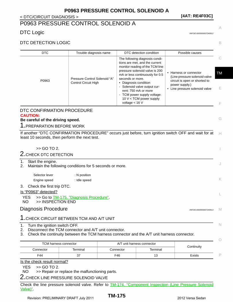
P0963 PRESSURE CONTROL SOLENOID A[4AT: RE4F03C]
C
E
F
G
H
I
J
K
L
M
A
B
M
N
O
P
< DTC/CIRCUIT DIAGNOSIS >
T
P0963 PRESSURE CONTROL SOLENOID A
DTC Logic INFOID:0000000007240912
DTC DETECTION LOGIC
DTC CONFIRMATION PROCEDURECAUTION:Be careful of the driving speed.
1.PREPARATION BEFORE WORK
If another “DTC CONFIRMATION PROCEDURE” occurs just before, turn ignition switch OFF and wait for atleast 10 seconds, then perform the next test.
>> GO TO 2.
2.CHECK DTC DETECTION
1. Start the engine.2. Maintain the following conditions for 5 seconds or more.
3. Check the first trip DTC.Is “P0963” detected?YES >> Go to TM-175, "Diagnosis Procedure".NO >> INSPECTION END
Diagnosis Procedure INFOID:0000000007240913
1.CHECK CIRCUIT BETWEEN TCM AND A/T UNIT
1. Turn the ignition switch OFF.2. Disconnect the TCM connector and A/T unit connector.3. Check the continuity between the TCM harness connector and the A/T unit harness connector.
Is the check result normal?YES >> GO TO 2.NO >> Repair or replace the malfunctioning parts.
2.CHECK LINE PRESSURE SOLENOID VALVE
Check the line pressure solenoid valve. Refer to TM-174, "Component Inspection (Line Pressure SolenoidValve)".
DTC Trouble diagnosis name DTC detection condition Possible causes
P0963Pressure Control Solenoid “A” Control Circuit High
The following diagnosis condi-tions are met, and the current monitor reading of the TCM line pressure solenoid valve is 200 mA or less continuously for 0.5 seconds or more.• Diagnosis condition- Solenoid valve output cur-
rent: 750 mA or more- TCM power supply voltage:
10 V < TCM power supply voltage < 16 V
• Harness or connector(Line pressure solenoid valve circuit is open or shorted to power supply.)
• Line pressure solenoid valve
Selector lever : N position
Engine speed : Idle speed
TCM harness connector A/T unit harness connectorContinuity
Connector Terminal Connector Terminal
F44 37 F46 13 Exists
TM-175Revision: PRELIMINARY DRAFT July 2011 2012 Versa Sedan

[4AT: RE4F03C]P0963 PRESSURE CONTROL SOLENOID A
< DTC/CIRCUIT DIAGNOSIS >Is the check result normal?YES >> Check intermittent incident. Refer to XX-XX, "*****".NO >> Repair or replace the malfunctioning parts.
Component Inspection (Line Pressure Solenoid Valve) INFOID:0000000007240914
1.CHECK LINE PRESSURE SOLENOID VALVE
Check the resistance between the A/T unit connector and ground.
Is the check result normal?YES >> INSPECTION ENDNO >> There is a malfunction of line pressure solenoid valve. Replace the transaxle assembly. Refer to
TM-242, "Removal and Installation".
A/T unit connectorGround Condition Resistance
Terminal
13 Ground
A/T fluid temperature: 20°C (68°F)
Approx. 6.1 Ω
A/T fluid temperature: 50°C (122°F)
Approx. 6.9 Ω
A/T fluid temperature: 80°C (176°F)
Approx. 7.7 Ω
TM-176Revision: PRELIMINARY DRAFT July 2011 2012 Versa Sedan

P0973 SHIFT SOLENOID A[4AT: RE4F03C]
C
E
F
G
H
I
J
K
L
M
A
B
M
N
O
P
< DTC/CIRCUIT DIAGNOSIS >
T
P0973 SHIFT SOLENOID A
DTC Logic INFOID:0000000007240915
DTC DETECTION LOGIC
DTC CONFIRMATION PROCEDURECAUTION:Be careful of the driving speed.
1.PREPARATION BEFORE WORK
If another “DTC CONFIRMATION PROCEDURE” occurs just before, turn ignition switch OFF and wait for atleast 10 seconds, then perform the next test.
>> GO TO 2.
2.CHECK DTC DETECTION
1. Start the engine.2. Maintain the following conditions for 5 seconds or more.
3. Check the first trip DTC.Is “P0973” detected?YES >> Go to TM-177, "Diagnosis Procedure".NO >> INSPECTION END
Diagnosis Procedure INFOID:0000000007240916
1.CHECK CIRCUIT BETWEEN TCM AND A/T UNIT
1. Turn the ignition switch OFF.2. Disconnect the TCM connector and A/T unit connector.3. Check the continuity between TCM harness connector and ground.
Is the check result normal?YES >> GO TO 2.NO >> Repair or replace the malfunctioning parts.
2.CHECK SELECT SWITCH ON-OFF SOLENOID VALVE
Check the select switch ON-OFF solenoid valve. Refer to TM-178, "Component Inspection (Select Switch ON-OFF Solenoid Valve)".
DTC Trouble diagnosis name DTC detection condition Possible causes
P0973Shift Solenoid “A” Control Cir-cuit Low
The following diagnosis condi-tions are met, and the TCM se-lect switch ON-OFF solenoid valve monitor value is ON con-tinuously for 0.5 seconds or more.• Diagnosis condition- select switch ON-OFF sole-
noid valve: OFF- TCM power supply voltage:
10 V < TCM power supply voltage < 16 V
• Harness or connector(Short circuit to ground in the select switch ON-OFF sole-noid valve circuit)
• Select switch ON-OFF sole-noid valve
Selector lever : N position ⇒ R position
TCM harness connectorGround Continuity
Connector Terminal
F44 1 Ground Does not exist
TM-177Revision: PRELIMINARY DRAFT July 2011 2012 Versa Sedan
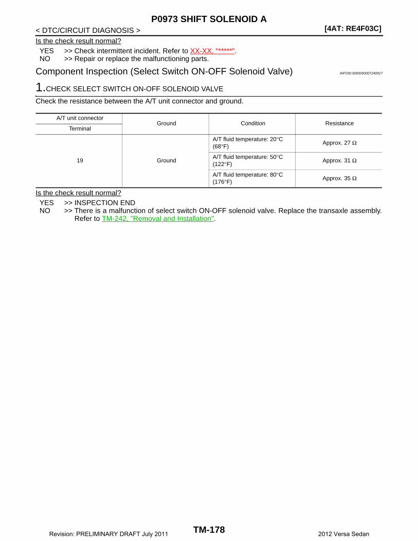
[4AT: RE4F03C]P0973 SHIFT SOLENOID A
< DTC/CIRCUIT DIAGNOSIS >Is the check result normal?YES >> Check intermittent incident. Refer to XX-XX, "*****".NO >> Repair or replace the malfunctioning parts.
Component Inspection (Select Switch ON-OFF Solenoid Valve) INFOID:0000000007240917
1.CHECK SELECT SWITCH ON-OFF SOLENOID VALVE
Check the resistance between the A/T unit connector and ground.
Is the check result normal?YES >> INSPECTION ENDNO >> There is a malfunction of select switch ON-OFF solenoid valve. Replace the transaxle assembly.
Refer to TM-242, "Removal and Installation".
A/T unit connectorGround Condition Resistance
Terminal
19 Ground
A/T fluid temperature: 20°C (68°F)
Approx. 27 Ω
A/T fluid temperature: 50°C (122°F)
Approx. 31 Ω
A/T fluid temperature: 80°C (176°F)
Approx. 35 Ω
TM-178Revision: PRELIMINARY DRAFT July 2011 2012 Versa Sedan
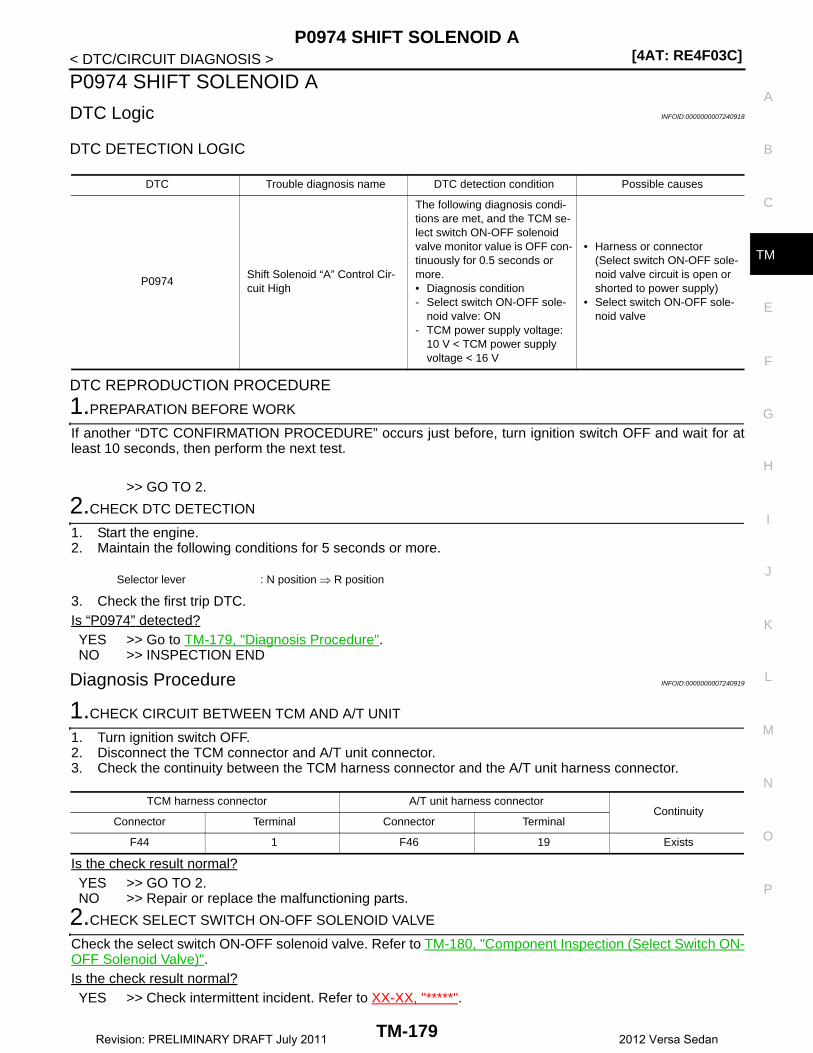
P0974 SHIFT SOLENOID A[4AT: RE4F03C]
C
E
F
G
H
I
J
K
L
M
A
B
M
N
O
P
< DTC/CIRCUIT DIAGNOSIS >
T
P0974 SHIFT SOLENOID A
DTC Logic INFOID:0000000007240918
DTC DETECTION LOGIC
DTC REPRODUCTION PROCEDURE
1.PREPARATION BEFORE WORK
If another “DTC CONFIRMATION PROCEDURE” occurs just before, turn ignition switch OFF and wait for atleast 10 seconds, then perform the next test.
>> GO TO 2.
2.CHECK DTC DETECTION
1. Start the engine.2. Maintain the following conditions for 5 seconds or more.
3. Check the first trip DTC.Is “P0974” detected?YES >> Go to TM-179, "Diagnosis Procedure".NO >> INSPECTION END
Diagnosis Procedure INFOID:0000000007240919
1.CHECK CIRCUIT BETWEEN TCM AND A/T UNIT
1. Turn ignition switch OFF.2. Disconnect the TCM connector and A/T unit connector.3. Check the continuity between the TCM harness connector and the A/T unit harness connector.
Is the check result normal?YES >> GO TO 2.NO >> Repair or replace the malfunctioning parts.
2.CHECK SELECT SWITCH ON-OFF SOLENOID VALVE
Check the select switch ON-OFF solenoid valve. Refer to TM-180, "Component Inspection (Select Switch ON-OFF Solenoid Valve)".Is the check result normal?YES >> Check intermittent incident. Refer to XX-XX, "*****".
DTC Trouble diagnosis name DTC detection condition Possible causes
P0974Shift Solenoid “A” Control Cir-cuit High
The following diagnosis condi-tions are met, and the TCM se-lect switch ON-OFF solenoid valve monitor value is OFF con-tinuously for 0.5 seconds or more.• Diagnosis condition- Select switch ON-OFF sole-
noid valve: ON- TCM power supply voltage:
10 V < TCM power supply voltage < 16 V
• Harness or connector(Select switch ON-OFF sole-noid valve circuit is open or shorted to power supply)
• Select switch ON-OFF sole-noid valve
Selector lever : N position ⇒ R position
TCM harness connector A/T unit harness connectorContinuity
Connector Terminal Connector Terminal
F44 1 F46 19 Exists
TM-179Revision: PRELIMINARY DRAFT July 2011 2012 Versa Sedan
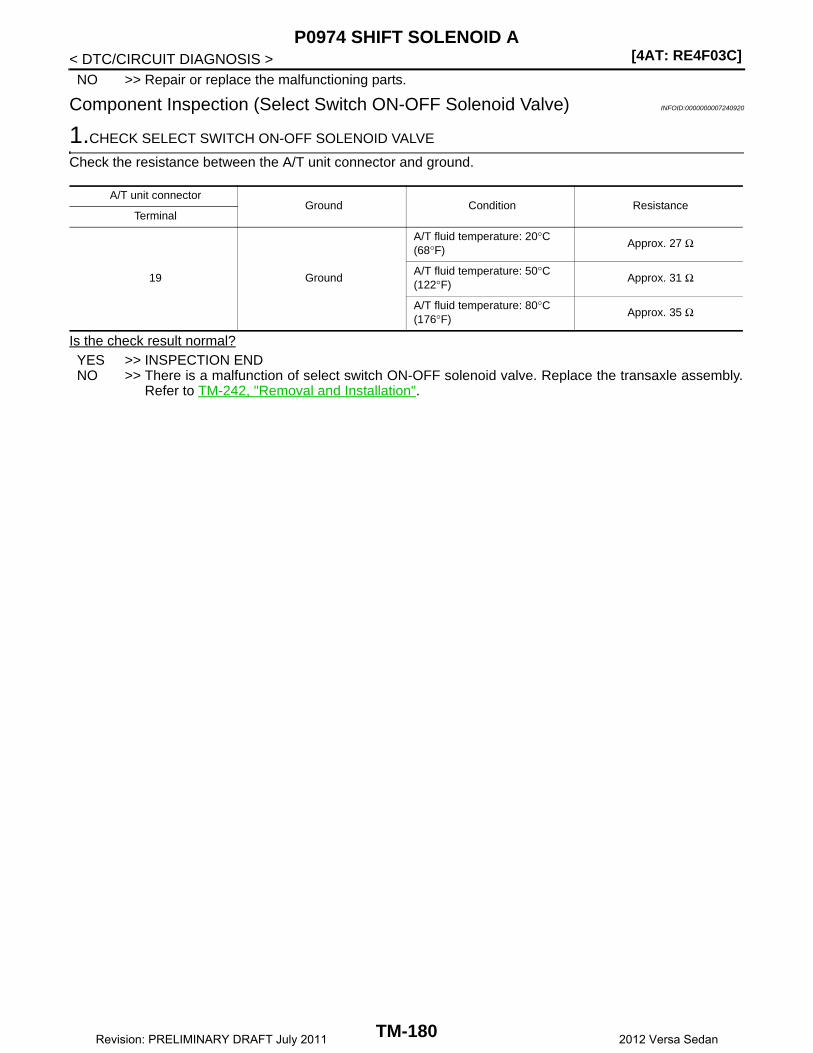
[4AT: RE4F03C]P0974 SHIFT SOLENOID A
< DTC/CIRCUIT DIAGNOSIS >NO >> Repair or replace the malfunctioning parts.
Component Inspection (Select Switch ON-OFF Solenoid Valve) INFOID:0000000007240920
1.CHECK SELECT SWITCH ON-OFF SOLENOID VALVE
Check the resistance between the A/T unit connector and ground.
Is the check result normal?YES >> INSPECTION ENDNO >> There is a malfunction of select switch ON-OFF solenoid valve. Replace the transaxle assembly.
Refer to TM-242, "Removal and Installation".
A/T unit connectorGround Condition Resistance
Terminal
19 Ground
A/T fluid temperature: 20°C (68°F)
Approx. 27 Ω
A/T fluid temperature: 50°C (122°F)
Approx. 31 Ω
A/T fluid temperature: 80°C (176°F)
Approx. 35 Ω
TM-180Revision: PRELIMINARY DRAFT July 2011 2012 Versa Sedan
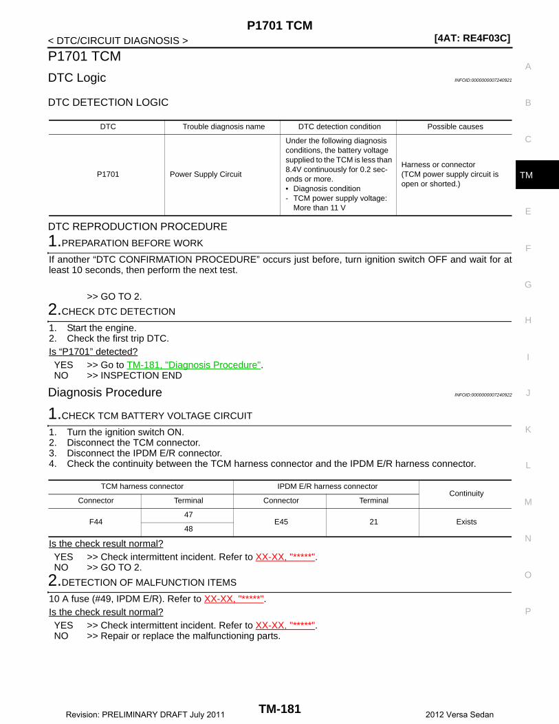
P1701 TCM[4AT: RE4F03C]
C
E
F
G
H
I
J
K
L
M
A
B
M
N
O
P
< DTC/CIRCUIT DIAGNOSIS >
T
P1701 TCM
DTC Logic INFOID:0000000007240921
DTC DETECTION LOGIC
DTC REPRODUCTION PROCEDURE
1.PREPARATION BEFORE WORK
If another “DTC CONFIRMATION PROCEDURE” occurs just before, turn ignition switch OFF and wait for atleast 10 seconds, then perform the next test.
>> GO TO 2.
2.CHECK DTC DETECTION
1. Start the engine.2. Check the first trip DTC.Is “P1701” detected?YES >> Go to TM-181, "Diagnosis Procedure".NO >> INSPECTION END
Diagnosis Procedure INFOID:0000000007240922
1.CHECK TCM BATTERY VOLTAGE CIRCUIT
1. Turn the ignition switch ON.2. Disconnect the TCM connector.3. Disconnect the IPDM E/R connector.4. Check the continuity between the TCM harness connector and the IPDM E/R harness connector.
Is the check result normal?YES >> Check intermittent incident. Refer to XX-XX, "*****".NO >> GO TO 2.
2.DETECTION OF MALFUNCTION ITEMS
10 A fuse (#49, IPDM E/R). Refer to XX-XX, "*****".Is the check result normal?YES >> Check intermittent incident. Refer to XX-XX, "*****".NO >> Repair or replace the malfunctioning parts.
DTC Trouble diagnosis name DTC detection condition Possible causes
P1701 Power Supply Circuit
Under the following diagnosis conditions, the battery voltage supplied to the TCM is less than 8.4V continuously for 0.2 sec-onds or more.• Diagnosis condition- TCM power supply voltage:
More than 11 V
Harness or connector(TCM power supply circuit is open or shorted.)
TCM harness connector IPDM E/R harness connectorContinuity
Connector Terminal Connector Terminal
F4447
E45 21 Exists48
TM-181Revision: PRELIMINARY DRAFT July 2011 2012 Versa Sedan
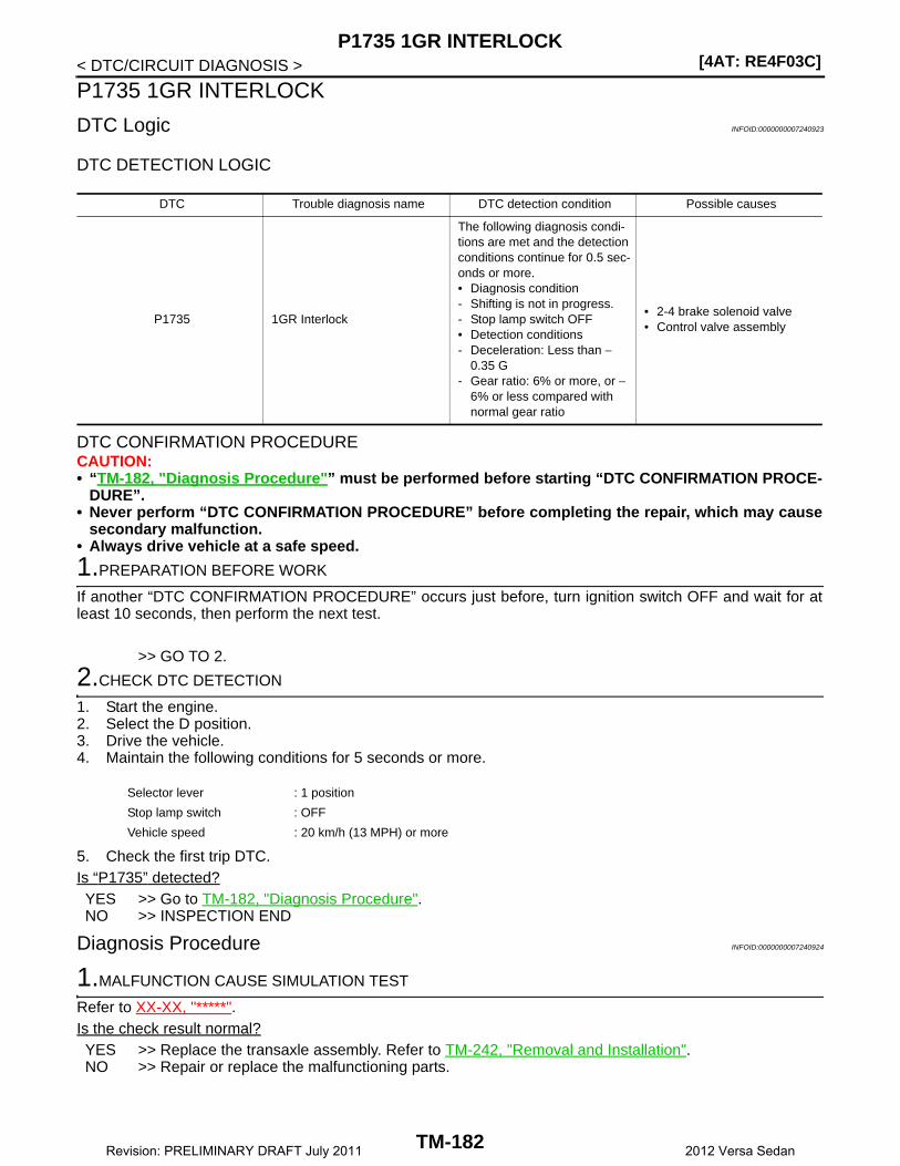
[4AT: RE4F03C]P1735 1GR INTERLOCK
< DTC/CIRCUIT DIAGNOSIS >
P1735 1GR INTERLOCK
DTC Logic INFOID:0000000007240923
DTC DETECTION LOGIC
DTC CONFIRMATION PROCEDURECAUTION:• “TM-182, "Diagnosis Procedure"” must be performed before starting “DTC CONFIRMATION PROCE-
DURE”.• Never perform “DTC CONFIRMATION PROCEDURE” before completing the repair, which may cause
secondary malfunction.• Always drive vehicle at a safe speed.
1.PREPARATION BEFORE WORK
If another “DTC CONFIRMATION PROCEDURE” occurs just before, turn ignition switch OFF and wait for atleast 10 seconds, then perform the next test.
>> GO TO 2.
2.CHECK DTC DETECTION
1. Start the engine.2. Select the D position.3. Drive the vehicle.4. Maintain the following conditions for 5 seconds or more.
5. Check the first trip DTC.Is “P1735” detected?YES >> Go to TM-182, "Diagnosis Procedure".NO >> INSPECTION END
Diagnosis Procedure INFOID:0000000007240924
1.MALFUNCTION CAUSE SIMULATION TEST
Refer to XX-XX, "*****". Is the check result normal?YES >> Replace the transaxle assembly. Refer to TM-242, "Removal and Installation".NO >> Repair or replace the malfunctioning parts.
DTC Trouble diagnosis name DTC detection condition Possible causes
P1735 1GR Interlock
The following diagnosis condi-tions are met and the detection conditions continue for 0.5 sec-onds or more.• Diagnosis condition- Shifting is not in progress.- Stop lamp switch OFF• Detection conditions- Deceleration: Less than −
0.35 G- Gear ratio: 6% or more, or −
6% or less compared with normal gear ratio
• 2-4 brake solenoid valve• Control valve assembly
Selector lever : 1 position
Stop lamp switch : OFF
Vehicle speed : 20 km/h (13 MPH) or more
TM-182Revision: PRELIMINARY DRAFT July 2011 2012 Versa Sedan

P1736 2GR INTERLOCK[4AT: RE4F03C]
C
E
F
G
H
I
J
K
L
M
A
B
M
N
O
P
< DTC/CIRCUIT DIAGNOSIS >
T
P1736 2GR INTERLOCK
DTC Logic INFOID:0000000007240925
DTC DETECTION LOGIC
DTC REPRODUCTION PROCEDURECAUTION:• “TM-183, "Diagnosis Procedure"” must be performed before starting “DTC CONFIRMATION PROCE-
DURE”.• Never perform “DTC CONFIRMATION PROCEDURE” before completing the repair, which may cause
secondary malfunction.• Always drive vehicle at a safe speed.
1.PREPARATION BEFORE WORK
If another “DTC CONFIRMATION PROCEDURE” occurs just before, turn ignition switch OFF and wait for atleast 10 seconds, then perform the next test.
>> GO TO 2.
2.CHECK DTC DETECTION
1. Start the engine.2. Drive the vehicle.3. Maintain the following conditions for 5 seconds or more.
4. Check the first trip DTC.Is “P1736” detected?YES >> Go to TM-183, "Diagnosis Procedure".NO >> INSPECTION END
Diagnosis Procedure INFOID:0000000007240926
1.MALFUNCTION CAUSE SIMULATION TEST
Refer to XX-XX, "*****". Is the check result normal?YES >> Replace the transaxle assembly. Refer to TM-242, "Removal and Installation".NO >> Repair or replace the malfunctioning parts.
DTC Trouble diagnosis name DTC detection condition Possible causes
P1736 2GR Interlock
The following diagnosis condi-tions are met and the detection conditions continue for 0.5 sec-onds or more.• Diagnosis condition- Shifting is not in progress.- Stop lamp switch OFF• Detection conditions- Deceleration: Less than –
0.35 G- Gear ratio: 6% or more, or −
6% or less compared with normal gear ratio
• High clutch/low & reverse brake solenoid valve
• Control valve assembly
Selector lever : 2 position
Gear : 2GR
Stop lamp switch : OFF
Vehicle speed : 20 km/h (13 MPH) or more
TM-183Revision: PRELIMINARY DRAFT July 2011 2012 Versa Sedan
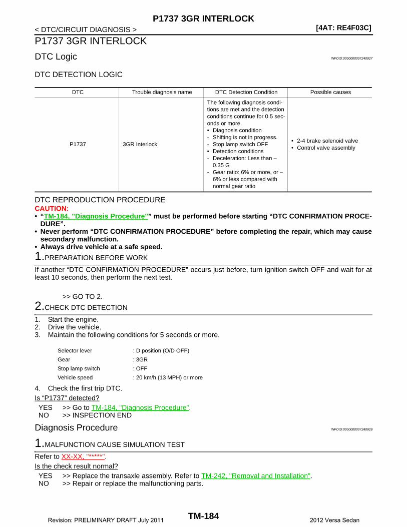
[4AT: RE4F03C]P1737 3GR INTERLOCK
< DTC/CIRCUIT DIAGNOSIS >
P1737 3GR INTERLOCK
DTC Logic INFOID:0000000007240927
DTC DETECTION LOGIC
DTC REPRODUCTION PROCEDURECAUTION:• “TM-184, "Diagnosis Procedure"” must be performed before starting “DTC CONFIRMATION PROCE-
DURE”.• Never perform “DTC CONFIRMATION PROCEDURE” before completing the repair, which may cause
secondary malfunction.• Always drive vehicle at a safe speed.
1.PREPARATION BEFORE WORK
If another “DTC CONFIRMATION PROCEDURE” occurs just before, turn ignition switch OFF and wait for atleast 10 seconds, then perform the next test.
>> GO TO 2.
2.CHECK DTC DETECTION
1. Start the engine.2. Drive the vehicle.3. Maintain the following conditions for 5 seconds or more.
4. Check the first trip DTC.Is “P1737” detected?YES >> Go to TM-184, "Diagnosis Procedure".NO >> INSPECTION END
Diagnosis Procedure INFOID:0000000007240928
1.MALFUNCTION CAUSE SIMULATION TEST
Refer to XX-XX, "*****". Is the check result normal?YES >> Replace the transaxle assembly. Refer to TM-242, "Removal and Installation".NO >> Repair or replace the malfunctioning parts.
DTC Trouble diagnosis name DTC Detection Condition Possible causes
P1737 3GR Interlock
The following diagnosis condi-tions are met and the detection conditions continue for 0.5 sec-onds or more.• Diagnosis condition- Shifting is not in progress.- Stop lamp switch OFF• Detection conditions- Deceleration: Less than –
0.35 G- Gear ratio: 6% or more, or −
6% or less compared with normal gear ratio
• 2-4 brake solenoid valve• Control valve assembly
Selector lever : D position (O/D OFF)
Gear : 3GR
Stop lamp switch : OFF
Vehicle speed : 20 km/h (13 MPH) or more
TM-184Revision: PRELIMINARY DRAFT July 2011 2012 Versa Sedan
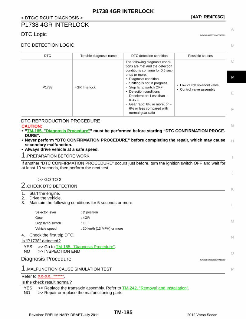
P1738 4GR INTERLOCK[4AT: RE4F03C]
C
E
F
G
H
I
J
K
L
M
A
B
M
N
O
P
< DTC/CIRCUIT DIAGNOSIS >
T
P1738 4GR INTERLOCK
DTC Logic INFOID:0000000007240929
DTC DETECTION LOGIC
DTC REPRODUCTION PROCEDURECAUTION:• “TM-185, "Diagnosis Procedure"” must be performed before starting “DTC CONFIRMATION PROCE-
DURE”.• Never perform “DTC CONFIRMATION PROCEDURE” before completing the repair, which may cause
secondary malfunction.• Always drive vehicle at a safe speed.
1.PREPARATION BEFORE WORK
If another “DTC CONFIRMATION PROCEDURE” occurs just before, turn the ignition switch OFF and wait forat least 10 seconds, then perform the next test.
>> GO TO 2.
2.CHECK DTC DETECTION
1. Start the engine.2. Drive the vehicle.3. Maintain the following conditions for 5 seconds or more.
4. Check the first trip DTC.Is “P1738” detected?YES >> Go to TM-185, "Diagnosis Procedure".NO >> INSPECTION END
Diagnosis Procedure INFOID:0000000007240930
1.MALFUNCTION CAUSE SIMULATION TEST
Refer to XX-XX, "*****". Is the check result normal?YES >> Replace the transaxle assembly. Refer to TM-242, "Removal and Installation".NO >> Repair or replace the malfunctioning parts.
DTC Trouble diagnosis name DTC detection condition Possible causes
P1738 4GR Interlock
The following diagnosis condi-tions are met and the detection conditions continue for 0.5 sec-onds or more.• Diagnosis condition- Shifting is not in progress.- Stop lamp switch OFF• Detection conditions- Deceleration: Less than −
0.35 G- Gear ratio: 6% or more, or −
6% or less compared with normal gear ratio
• Low clutch solenoid valve• Control valve assembly
Selector lever : D position
Gear : 4GR
Stop lamp switch : OFF
Vehicle speed : 20 km/h (13 MPH) or more
TM-185Revision: PRELIMINARY DRAFT July 2011 2012 Versa Sedan
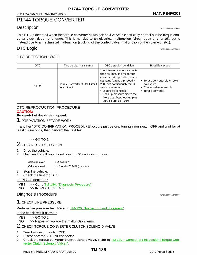
[4AT: RE4F03C]P1744 TORQUE CONVERTER
< DTC/CIRCUIT DIAGNOSIS >
P1744 TORQUE CONVERTER
Description INFOID:0000000007240931
This DTC is detected when the torque converter clutch solenoid valve is electrically normal but the torque con-verter clutch does not engage. This is not due to an electrical malfunction (circuit open or shorted), but isinstead due to a mechanical malfunction (sticking of the control valve, malfunction of the solenoid, etc.).
DTC Logic INFOID:0000000007240932
DTC DETECTION LOGIC
DTC REPRODUCTION PROCEDURECAUTION:Be careful of the driving speed.
1.PREPARATION BEFORE WORK
If another “DTC CONFIRMATION PROCEDURE” occurs just before, turn ignition switch OFF and wait for atleast 10 seconds, then perform the next test.
>> GO TO 2.
2.CHECK DTC DETECTION
1. Drive the vehicle.2. Maintain the following conditions for 40 seconds or more.
3. Stop the vehicle.4. Check the first trip DTC.Is “P1744” detected?YES >> Go to TM-186, "Diagnosis Procedure".NO >> INSPECTION END
Diagnosis Procedure INFOID:0000000007240933
1.CHECK LINE PRESSURE
Perform line pressure test. Refer to TM-126, "Inspection and Judgment".Is the check result normal?YES >> GO TO 2.NO >> Repair or replace the malfunction items.
2.CHECK TORQUE CONVERTER CLUTCH SOLENOID VALVE
1. Turn the ignition switch OFF.2. Disconnect the A/T unit connector.3. Check the torque converter clutch solenoid valve. Refer to TM-187, "Component Inspection (Torque Con-
verter Clutch Solenoid Valve)".
DTC Trouble diagnosis name DTC detection condition Possible causes
P1744Torque Converter Clutch Circuit Intermittent
The following diagnosis condi-tions are met, and the torque converter slip speed is above a set value (target slip speed + 200 rpm) continuously for 30 seconds or more.• Diagnosis condition- Lock-up pressure difference:
More than Max. lock-up pres-sure difference × 0.95
• Torque converter clutch sole-noid valve
• Control valve assembly• Torque converter
Selector lever : D position
Vehicle speed : 45 km/h (28 MPH) or more
TM-186Revision: PRELIMINARY DRAFT July 2011 2012 Versa Sedan

P1744 TORQUE CONVERTER[4AT: RE4F03C]
C
E
F
G
H
I
J
K
L
M
A
B
M
N
O
P
< DTC/CIRCUIT DIAGNOSIS >
T
Is the check result normal?YES >> Check intermittent incident. Refer to XX-XX, "*****".NO >> Repair or replace the malfunction items.
Component Inspection (Torque Converter Clutch Solenoid Valve) INFOID:0000000007240934
1.CHECK TORQUE CONVERTER CLUTCH SOLENOID VALVE
Check the resistance between the A/T unit connector terminal and ground.
Is the check result normal?YES >> INSPECTION ENDNO >> There is a malfunction of the torque converter clutch solenoid valve. Replace the transaxle
assembly. Refer to TM-242, "Removal and Installation".
A/T unit connectorGround Condition Resistance
Terminal
18 Ground
A/T fluid temperature: 20°C (68°F)
Approx. 6.1 Ω
A/T fluid temperature: 50°C (122°F)
Approx. 6.9 Ω
A/T fluid temperature: 80°C (176°F)
Approx. 7.7 Ω
TM-187Revision: PRELIMINARY DRAFT July 2011 2012 Versa Sedan

[4AT: RE4F03C]P17A0 R GR INCORRECT RATIO
< DTC/CIRCUIT DIAGNOSIS >
P17A0 R GR INCORRECT RATIO
Description INFOID:0000000007240935
This malfunction is detected when the A/T does not shift into reverse position as instructed by TCM. This is notonly caused by electrical malfunction (circuits open or shorted) but by mechanical malfunction such as controlvalve sticking, improper solenoid valve operation, etc.
DTC Logic INFOID:0000000007240936
DTC DETECTION LOGIC
DTC CONFIRMATION PROCEDURECAUTION:• “TM-189, "Diagnosis Procedure"” must be performed before starting “DTC CONFIRMATION PROCE-
DURE”.• Never perform “DTC CONFIRMATION PROCEDURE” before completing the repair, which may cause
secondary malfunction.• Always drive vehicle at a safe speed.
1.PREPARATION BEFORE WORK
If another “DTC CONFIRMATION PROCEDURE” occurs just before, turn ignition switch OFF and wait for atleast 10 seconds, then perform the next test.
>> GO TO 2.
2.CHECK DTC DETECTION
With CONSULT1. Select “R POSITION FNCTN” in “DTC & SRT confirmation” in “TRANSMISSION”.2. Drive vehicle according to the following conditions.
3. Keep the current driving status for 2 seconds or more if CONSULT screen changes from “OUT OFCONDI-TION” to “TESTING”.CAUTION:When “TESTING” is not indicated on CONSULT for a long time, check “Self Diagnostic Results” in“TRANSMISSION”. When a DTC other than “P17A0” is detected, check the DTC. Refer to TM-106,"DTC Index".
With GST1. Start the engine.2. Drive vehicle and maintain the following conditions for 2 seconds or more.
DTC Trouble diagnosis name DTC detection condition Possible causes
P17A0 R Gear Incorrect Ratio
Under the following diagnosis conditions, the gear ratio is 2.449 or more continuously for 2 seconds or more.• Diagnosis condition- Shifting is not in progress.- Input speed: 300 rpm or more- Output speed: 300 rpm or
more- Engine speed: (Input speed –
50 rpm) or more- Selector lever: R position- Throttle position: 0.7/8.0 or
more
• High clutch/low & reverse brake solenoid valve
• Control valve assembly
Selector lever : R position
Throttle position : 0.7/8 or more
Vehicle speed : 5 km/h (8 MPH) or more
TM-188Revision: PRELIMINARY DRAFT July 2011 2012 Versa Sedan

P17A0 R GR INCORRECT RATIO[4AT: RE4F03C]
C
E
F
G
H
I
J
K
L
M
A
B
M
N
O
P
< DTC/CIRCUIT DIAGNOSIS >
T
3. Check the first trip DTC.Is “OUT OF CONDITION”, “STOP VEHICLE” or “COMPLETED RESULT NG” displayed? / Is “P17A0”detected?YES-1 (OUT OF CONDITION.)>>Perform “step 2” again.YES-2 (STOP VEHICLE.)>>INSPECTION ENDYES-3 (COMPLETED RESULT NG)>>Go to TM-189, "Diagnosis Procedure".YES-4 (“P17A0” is detected.)>>Go to TM-189, "Diagnosis Procedure".NO >> INSPECTION END
Diagnosis Procedure INFOID:0000000007240937
1.MALFUNCTION CAUSE SIMULATION TEST
Refer to XX-XX, "*****". Is the check result normal?YES >> Replace the transaxle assembly. Refer to TM-242, "Removal and Installation".NO >> Repair or replace the malfunctioning parts.
Selector lever : R position
Throttle position : 0.7/8 or more
Vehicle speed : 5 km/h (8 MPH) or more
TM-189Revision: PRELIMINARY DRAFT July 2011 2012 Versa Sedan

[4AT: RE4F03C]P17A1 1GR INCORRECT RATIO
< DTC/CIRCUIT DIAGNOSIS >
P17A1 1GR INCORRECT RATIO
Description INFOID:0000000007240938
This malfunction is detected when the A/T does not shift into 1GR position as instructed by TCM. This is notonly caused by electrical malfunction (circuits open or shorted) but by mechanical malfunction such as controlvalve sticking, improper solenoid valve operation, etc.
DTC Logic INFOID:0000000007240939
DTC DETECTION LOGIC
DTC CONFIRMATION PROCEDURECAUTION:• “TM-192, "Diagnosis Procedure"” must be performed before starting “DTC CONFIRMATION PROCE-
DURE”.• Never perform “DTC CONFIRMATION PROCEDURE” before completing the repair, which may cause
secondary malfunction.• Always drive vehicle at a safe speed.
1.PREPARATION BEFORE WORK
If another “DTC CONFIRMATION PROCEDURE” occurs just before, turn ignition switch OFF and wait for atleast 10 seconds, then perform the next test.
>> GO TO 2.
2.CHECK DTC DETECTION (CHECK 1)
With CONSULT1. Select “1ST GR FNCTN P0731” in “DTC & SRT confirmation” in “TRANSMISSION”.
NOTE:“1ST GR FNCTN P0731” can be used in this diagnosis.
2. Drive vehicle according to the following conditions.
DTC Trouble diagnosis name DTC detection condition Possible causes
P17A1 1GR Incorrect Ratio
Under the following diagnosis conditions, the gear ratio is 3.033 or more continuously for 2 seconds or more.• Diagnosis condition- Shifting is not in progress.- Input speed: 300 rpm or more- Output speed: 300 rpm or
more- Engine speed: (Input speed –
50 rpm) or more−- Selector lever: D position- Gear: 1st- Throttle position: 3/8 or more
• Low clutch solenoid valve• Control valve assembly
Under the following diagnosis conditions, the gear ratio is 3.033 or more continuously for 2 seconds or more.• Diagnosis condition- Shifting is not in progress.- Input speed: 300 rpm or more- Output speed: 300 rpm or
more- Engine speed: (Input speed –
50 rpm) or more- Selector lever: 1 position- Throttle position: 0.7/8 or
more
• Low clutch solenoid valve• Control valve assembly
TM-190Revision: PRELIMINARY DRAFT July 2011 2012 Versa Sedan

P17A1 1GR INCORRECT RATIO[4AT: RE4F03C]
C
E
F
G
H
I
J
K
L
M
A
B
M
N
O
P
< DTC/CIRCUIT DIAGNOSIS >
T
3. Keep the current driving status for 2 seconds or more if CONSULT screen changes from “OUT OFCONDI-TION” to “TESTING”.CAUTION:When “TESTING” is not indicated on CONSULT for a long time, check “Self Diagnostic Results” in“TRANSMISSION”. When a DTC other than “P17A1” is detected, check the DTC. Refer to TM-106,"DTC Index".
With GST1. Drive vehicle and maintain the following conditions for 2 seconds or more.
2. Check the first trip DTC.Is “OUT OF CONDITION”, “STOP VEHICLE”, or “COMPLETED RESULT NG” displayed? / Is “P17A1”detected?YES-1 (OUT OF CONDITION.)>>Perform “step 2” again.YES-2 (STOP VEHICLE.)>>GO TO 3.YES-3 (COMPLETED RESULT NG)>>Go to TM-192, "Diagnosis Procedure".YES-4 (“P17A1” is detected.)>>Go to TM-192, "Diagnosis Procedure".NO >> GO TO 3.
3.CHECK DTC DETECTION (CHECK 2)
With CONSULT1. Select “1ST GR FNCTN P0731” in “DTC & SRT confirmation” in “TRANSMISSION”.
NOTE:“1ST GR FNCTN P0731” can be used in this diagnosis.
2. Drive vehicle according to the following conditions.
3. Keep the current driving status for 2 seconds or more if CONSULT screen changes from “OUT OFCONDI-TION” to “TESTING”.CAUTION:When “TESTING” is not indicated on CONSULT for a long time, check “Self Diagnostic Results” in“TRANSMISSION”. When a DTC other than “P17A1” is detected, check the DTC. Refer to TM-106,"DTC Index".
With GST1. Drive vehicle and maintain the following conditions for 2 seconds or more.
2. Check the first trip DTC.Is “OUT OF CONDITION”, “STOP VEHICLE”, or “COMPLETED RESULT NG” displayed? / Is “P17A1”detected?YES-1 (OUT OF CONDITION.)>>Perform step 3 again.YES-2 (STOP VEHICLE.)>>GO TO 4.YES-3 (COMPLETED RESULT NG)>>Go to TM-192, "Diagnosis Procedure".YES-4 (“P17A1” is detected.)>>Go to TM-192, "Diagnosis Procedure".
Selector lever : D position
Gear : 1GR
Accelerator pedal position : 3/8 or more
Vehicle speed : 5 km/h (4 MPH) or more
Selector lever : D position
Gear : 1GR
Accelerator pedal position : 3/8 or more
Vehicle speed : 5 km/h (4 MPH) or more
Selector lever : 1 position
Accelerator pedal position : 0.7/8 or more
Vehicle speed : 5 km/h (4 MPH) or more
Selector lever : 1 position
Throttle position : 0.7/8 or more
Vehicle speed : 5 km/h (4 MPH) or more
TM-191Revision: PRELIMINARY DRAFT July 2011 2012 Versa Sedan

[4AT: RE4F03C]P17A1 1GR INCORRECT RATIO
< DTC/CIRCUIT DIAGNOSIS >NO >> GO TO 4.
4.CHECK SYMPTOM
1. Stop the vehicle.2. Drive vehicle in “D” position allowing it to shift from 1GR to 4GR and check shift timing and shift shock.
>> INSPECTION END
Diagnosis Procedure INFOID:0000000007240940
1.MALFUNCTION CAUSE SIMULATION TEST
Refer to XX-XX, "*****". Is the check result normal?YES >> Replace the transaxle assembly. Refer to TM-242, "Removal and Installation".NO >> Repair or replace the malfunctioning parts.
TM-192Revision: PRELIMINARY DRAFT July 2011 2012 Versa Sedan

P17A2 2GR INCORRECT RATIO[4AT: RE4F03C]
C
E
F
G
H
I
J
K
L
M
A
B
M
N
O
P
< DTC/CIRCUIT DIAGNOSIS >
T
P17A2 2GR INCORRECT RATIO
Description INFOID:0000000007240941
This malfunction is detected when the A/T does not shift into 2GR position as instructed by TCM. This is notonly caused by electrical malfunction (circuits open or shorted) but by mechanical malfunction such as controlvalve sticking, improper solenoid valve operation, etc.
DTC Logic INFOID:0000000007240942
DTC DETECTION LOGIC
DTC CONFIRMATION PROCEDURECAUTION:• “TM-194, "Diagnosis Procedure"” must be performed before starting “DTC CONFIRMATION PROCE-
DURE”.• Never perform “DTC CONFIRMATION PROCEDURE” before completing the repair, which may cause
secondary malfunction.• Always drive vehicle at a safe speed.
1.PREPARATION BEFORE WORK
If another “DTC CONFIRMATION PROCEDURE” occurs just before, turn ignition switch OFF and wait for atleast 10 seconds, then perform the next test.
>> GO TO 2.
2.CHECK DTC DETECTION
With CONSULT1. Select “2ND GR FNCTN P0732” in “DTC & SRT confirmation” in “TRANSMISSION”.
NOTE:“2ND GR FNCTN P0731” can be used in this diagnosis.
2. Drive vehicle according to the following conditions.
3. Keep the current driving status for 2 seconds or more if CONSULT screen changes from “OUT OFCONDI-TION” to “TESTING”.CAUTION:When “TESTING” is not indicated on CONSULT for a long time, check “Self Diagnostic Results” in“TRANSMISSION”. When a DTC other than “P17A2” is detected, check the DTC. Refer to TM-106,"DTC Index".
DTC Trouble diagnosis name DTC detection condition Possible causes
P17A2 2GR Incorrect Ratio
Under the following diagnosis conditions, the gear ratio is 3.033 or more continuously for 2 seconds or more.• Diagnosis condition- Shifting is not in progress.- Input speed: 300 rpm or more- Output speed: 300 rpm or
more- Engine speed: (Input speed –
50 rpm) or more- Selector lever: 2 position- Gear: 2GR- Throttle position: 0.7/8.0 or
more
• Low clutch solenoid valve• Control valve assembly
Selector lever : 2 position
Gear : 2GR
Accelerator pedal position : 0.7/8 or more
Vehicle speed : 5 km/h (4 MPH) or more
TM-193Revision: PRELIMINARY DRAFT July 2011 2012 Versa Sedan

[4AT: RE4F03C]P17A2 2GR INCORRECT RATIO
< DTC/CIRCUIT DIAGNOSIS >
With GST1. Drive vehicle and maintain the following conditions for 2 seconds or more.
2. Check the first trip DTC.Is “OUT OF CONDITION”, “STOP VEHICLE”, or “COMPLETED RESULT NG” displayed? / Is “P17A2”detected?YES-1 (OUT OF CONDITION.)>>Perform “step 2” again.YES-2 (STOP VEHICLE.)>>GO TO 3.YES-3 (COMPLETED RESULT NG)>>Go to TM-194, "Diagnosis Procedure".YES-4 (“P17A2” is detected.)>>Go to TM-194, "Diagnosis Procedure".NO >> GO TO 3.
3.CHECK SYMPTOM
1. Stop the vehicle.2. Drive vehicle in “D” position allowing it to shift from 1GR to 4GR and check shift timing and shift shock.
>> INSPECTION END
Diagnosis Procedure INFOID:0000000007240943
1.MALFUNCTION CAUSE SIMULATION TEST
Refer to XX-XX, "*****". Is the check result normal?YES >> Replace the transaxle assembly. Refer to TM-242, "Removal and Installation".NO >> Repair or replace the malfunctioning parts.
Selector lever : 2 position
Gear : 2GR
Accelerator pedal position : 0.7/8 or more
Vehicle speed : 5 km/h (4 MPH) or more
TM-194Revision: PRELIMINARY DRAFT July 2011 2012 Versa Sedan
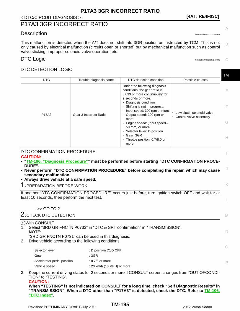
P17A3 3GR INCORRECT RATIO[4AT: RE4F03C]
C
E
F
G
H
I
J
K
L
M
A
B
M
N
O
P
< DTC/CIRCUIT DIAGNOSIS >
T
P17A3 3GR INCORRECT RATIO
Description INFOID:0000000007240944
This malfunction is detected when the A/T does not shift into 3GR position as instructed by TCM. This is notonly caused by electrical malfunction (circuits open or shorted) but by mechanical malfunction such as controlvalve sticking, improper solenoid valve operation, etc.
DTC Logic INFOID:0000000007240945
DTC DETECTION LOGIC
DTC CONFIRMATION PROCEDURECAUTION:• “TM-196, "Diagnosis Procedure"” must be performed before starting “DTC CONFIRMATION PROCE-
DURE”.• Never perform “DTC CONFIRMATION PROCEDURE” before completing the repair, which may cause
secondary malfunction.• Always drive vehicle at a safe speed.
1.PREPARATION BEFORE WORK
If another “DTC CONFIRMATION PROCEDURE” occurs just before, turn ignition switch OFF and wait for atleast 10 seconds, then perform the next test.
>> GO TO 2.
2.CHECK DTC DETECTION
With CONSULT1. Select “3RD GR FNCTN P0733” in “DTC & SRT confirmation” in “TRANSMISSION”.
NOTE:“3RD GR FNCTN P0731” can be used in this diagnosis.
2. Drive vehicle according to the following conditions.
3. Keep the current driving status for 2 seconds or more if CONSULT screen changes from “OUT OFCONDI-TION” to “TESTING”.CAUTION:When “TESTING” is not indicated on CONSULT for a long time, check “Self Diagnostic Results” in“TRANSMISSION”. When a DTC other than “P17A3” is detected, check the DTC. Refer to TM-106,"DTC Index".
DTC Trouble diagnosis name DTC detection condition Possible causes
P17A3 Gear 3 Incorrect Ratio
Under the following diagnosis conditions, the gear ratio is 3.033 or more continuously for 2 seconds or more.• Diagnosis condition- Shifting is not in progress.- Input speed: 300 rpm or more- Output speed: 300 rpm or
more- Engine speed: (Input speed –
50 rpm) or more- Selector lever: D position- Gear: 3GR- Throttle position: 0.7/8.0 or
more
• Low clutch solenoid valve• Control valve assembly
Selector lever : D position (O/D OFF)
Gear : 3GR
Accelerator pedal position : 0.7/8 or more
Vehicle speed : 20 km/h (13 MPH) or more
TM-195Revision: PRELIMINARY DRAFT July 2011 2012 Versa Sedan

[4AT: RE4F03C]P17A3 3GR INCORRECT RATIO
< DTC/CIRCUIT DIAGNOSIS >
With GST1. Drive vehicle and maintain the following conditions for 2 seconds or more.
2. Check the first trip DTC.Is “OUT OF CONDITION”, “STOP VEHICLE”, or “COMPLETED RESULT NG” displayed? / Is “P17A3”detected?YES-1 (OUT OF CONDITION.)>>Perform “step 2” again.YES-2 (STOP VEHICLE.)>>GO TO 3.YES-3 (COMPLETED RESULT NG)>>Go to TM-196, "Diagnosis Procedure".YES-4 (“P17A3” is detected.)>>Go to TM-196, "Diagnosis Procedure".NO >> GO TO 3.
3.CHECK SYMPTOM
1. Stop the vehicle.2. Drive vehicle in “D” position allowing it to shift from 1GR to 4GR and check shift timing and shift shock.
>> INSPECTION END
Diagnosis Procedure INFOID:0000000007240946
1.MALFUNCTION CAUSE SIMULATION TEST
Refer to XX-XX, "*****". Is the check result normal?YES >> Replace the transaxle assembly. Refer to TM-242, "Removal and Installation".NO >> Repair or replace the malfunctioning parts.
Selector lever : D position (O/D OFF)
Gear : 3GR
Accelerator pedal position : 0.7/8 or more
Vehicle speed : 20 km/h (13 MPH) or more
TM-196Revision: PRELIMINARY DRAFT July 2011 2012 Versa Sedan

P17A4 4GR INCORRECT RATIO[4AT: RE4F03C]
C
E
F
G
H
I
J
K
L
M
A
B
M
N
O
P
< DTC/CIRCUIT DIAGNOSIS >
T
P17A4 4GR INCORRECT RATIO
Description INFOID:0000000007240947
This malfunction is detected when the A/T does not shift into 4GR position as instructed by TCM. This is notonly caused by electrical malfunction (circuits open or shorted) but by mechanical malfunction such as controlvalve sticking, improper solenoid valve operation, etc.
DTC Logic INFOID:0000000007240948
DTC DETECTION LOGIC
DTC CONFIRMATION PROCEDURECAUTION:• “TM-198, "Diagnosis Procedure"” must be performed before starting “DTC CONFIRMATION PROCE-
DURE”.• Never perform “DTC CONFIRMATION PROCEDURE” before completing the repair, which may cause
secondary malfunction.• Always drive vehicle at a safe speed.
1.PREPARATION BEFORE WORK
If another “DTC CONFIRMATION PROCEDURE” occurs just before, turn ignition switch OFF and wait for atleast 10 seconds, then perform the next test.
>> GO TO 2.
2.CHECK DTC DETECTION
With CONSULT1. Select “4TH GR FNCTN P0734” in “DTC & SRT confirmation” in “TRANSMISSION”.
NOTE:"4TH GR FNCTN P0731" can be used in this diagnosis.
2. Drive vehicle according to the following conditions.
3. Keep the current driving status for 2 seconds or more if CONSULT screen changes from “OUT OFCONDI-TION” to “TESTING”.CAUTION:When “TESTING” is not indicated on CONSULT for a long time, check “Self Diagnostic Results” in“TRANSMISSION”. When a DTC other than “P17A4” is detected, check the DTC. Refer to TM-106,"DTC Index".
DTC Trouble diagnosis name DTC detection condition Possible causes
P17A4 Gear 4 Incorrect Ratio
Under the following diagnosis conditions, the gear ratio is 1.060 or more continuously for 2 seconds or more.• Diagnosis condition- Shifting is not in progress.- Input speed: 300 rpm or more- Output speed: 300 rpm or
more- Engine speed: (Input speed –
50 rpm) or more- Selector lever: D position- Gear: 4GR- Throttle position: 0.7/8.0 or
more
• High clutch/low & reverse brake solenoid valve
• 2-4 brake solenoid valve• Control valve assembly
Selector lever : D position
Gear : 4GR
Accelerator pedal position : 0.7/8 or more
Vehicle speed : 20 km/h (13MPH) or more
TM-197Revision: PRELIMINARY DRAFT July 2011 2012 Versa Sedan
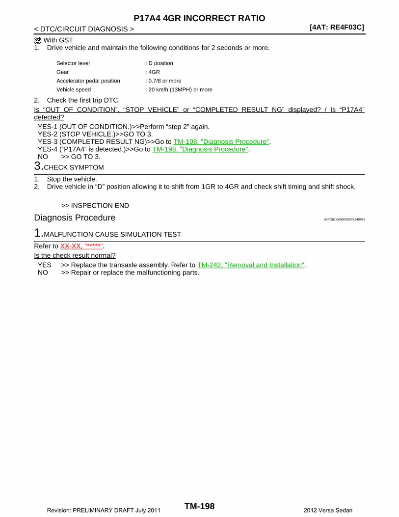
[4AT: RE4F03C]P17A4 4GR INCORRECT RATIO
< DTC/CIRCUIT DIAGNOSIS >
With GST1. Drive vehicle and maintain the following conditions for 2 seconds or more.
2. Check the first trip DTC.Is “OUT OF CONDITION”, “STOP VEHICLE” or “COMPLETED RESULT NG” displayed? / Is “P17A4”detected?YES-1 (OUT OF CONDITION.)>>Perform “step 2” again.YES-2 (STOP VEHICLE.)>>GO TO 3.YES-3 (COMPLETED RESULT NG)>>Go to TM-198, "Diagnosis Procedure".YES-4 (“P17A4” is detected.)>>Go to TM-198, "Diagnosis Procedure".NO >> GO TO 3.
3.CHECK SYMPTOM
1. Stop the vehicle.2. Drive vehicle in “D” position allowing it to shift from 1GR to 4GR and check shift timing and shift shock.
>> INSPECTION END
Diagnosis Procedure INFOID:0000000007240949
1.MALFUNCTION CAUSE SIMULATION TEST
Refer to XX-XX, "*****". Is the check result normal?YES >> Replace the transaxle assembly. Refer to TM-242, "Removal and Installation".NO >> Repair or replace the malfunctioning parts.
Selector lever : D position
Gear : 4GR
Accelerator pedal position : 0.7/8 or more
Vehicle speed : 20 km/h (13MPH) or more
TM-198Revision: PRELIMINARY DRAFT July 2011 2012 Versa Sedan

P17AA LOW CLUTCH SOLENOID[4AT: RE4F03C]
C
E
F
G
H
I
J
K
L
M
A
B
M
N
O
P
< DTC/CIRCUIT DIAGNOSIS >
T
P17AA LOW CLUTCH SOLENOID
DTC Logic INFOID:0000000007240950
DTC DETECTION LOGIC
DTC REPRODUCTION PROCEDURECAUTION:Be careful of the driving speed.
1.PREPARATION BEFORE WORK
If another “DTC CONFIRMATION PROCEDURE” occurs just before, turn ignition switch OFF and wait for atleast 10 seconds, then perform the next test.
>> GO TO 2.
2.CHECK DTC DETECTION
1. Drive the vehicle.2. Maintain the following conditions for 5 seconds or more.
3. Stop the vehicle.4. Check the first trip DTC.Is “P17AA” detected?YES >> Go to TM-207, "Diagnosis Procedure".NO >> INSPECTION END
Diagnosis Procedure INFOID:0000000007240951
1.CHECK CIRCUIT BETWEEN TCM AND A/T UNIT
1. Turn the ignition switch OFF.2. Disconnect the TCM connector and A/T unit connector.3. Check the continuity between TCM harness connector and ground.
Is the check result normal?YES >> GO TO 2.
DTC Trouble diagnosis name DTC detection condition Possible causes
P17AA Low Clutch Solenoid Circuit
The following diagnosis condi-tions are met, and the TCM low clutch solenoid valve current monitor reading is 200 mA or less continuously for 0.5 sec-onds or more.• Diagnosis condition- Solenoid valve output cur-
rent: 750 mA or more- GND short circuit diagnosis
occurs in the solenoid valve drive circuit.
- TCM power supply voltage: 10 V < TCM power supply voltage < 16 V
• Harness or connector(Short circuit to ground in the low clutch solenoid valve cir-cuit)
• Low clutch solenoid valve
Selector lever : D position
Gear : 1GR, 2GR, 3GR
Vehicle speed : 5 km/h (4 MPH) or more
TCM harness connectorGround Continuity
Connector Terminal
F44 30 Ground Does not exist
TM-199Revision: PRELIMINARY DRAFT July 2011 2012 Versa Sedan

[4AT: RE4F03C]P17AA LOW CLUTCH SOLENOID
< DTC/CIRCUIT DIAGNOSIS >NO >> Repair or replace the malfunctioning parts.
2.CHECK LOW CLUTCH SOLENOID VALVE
Check the low clutch solenoid valve. Refer to TM-200, "Component Inspection (Low Clutch Solenoid Valve)".Is the check result normal?YES >> Check intermittent incident. Refer to XX-XX, "*****".NO >> Repair or replace the malfunctioning parts.
Component Inspection (Low Clutch Solenoid Valve) INFOID:0000000007240952
1.CHECK LOW CLUTCH SOLENOID VALVE
Check the resistance between the A/T unit connector and ground.
Is the check result normal?YES >> INSPECTION ENDNO >> There is a malfunction of the low clutch solenoid valve. Replace the transaxle assembly. Refer to
TM-242, "Removal and Installation".
A/T unit connectorGround Condition Resistance
Terminal
6 Ground
A/T fluid temperature: 20°C (68°F)
Approx. 6.2 Ω
A/T fluid temperature: 50°C (122°F)
Approx. 7.0 Ω
A/T fluid temperature: 80°C (176°F)
Approx. 7.8 Ω
TM-200Revision: PRELIMINARY DRAFT July 2011 2012 Versa Sedan

P17AB LOW CLUTCH SOLENOID[4AT: RE4F03C]
C
E
F
G
H
I
J
K
L
M
A
B
M
N
O
P
< DTC/CIRCUIT DIAGNOSIS >
T
P17AB LOW CLUTCH SOLENOID
DTC Logic INFOID:0000000007240953
DTC DETECTION LOGIC
DTC REPRODUCTION PROCEDURECAUTION:Be careful of the driving speed.
1.PREPARATION BEFORE WORK
If another “DTC CONFIRMATION PROCEDURE” occurs just before, turn ignition switch OFF and wait for atleast 10 seconds, then perform the next test.
>> GO TO 2.
2.CHECK DTC DETECTION
1. Drive the vehicle.2. Maintain the following conditions for 5 seconds or more.
3. Stop the vehicle.4. Check the first trip DTC.Is “P17AB” detected?YES >> Go to TM-209, "Diagnosis Procedure".NO >> INSPECTION END
Diagnosis Procedure INFOID:0000000007240954
1.CHECK CIRCUIT BETWEEN TCM AND A/T UNIT
1. Turn ignition switch OFF.2. Disconnect the TCM connector and A/T unit connector.3. Check the continuity between the TCM harness connector and the A/T unit harness connector.
Is the check result normal?YES >> GO TO 2.NO >> Repair or replace the malfunctioning parts.
DTC Trouble diagnosis name DTC detection condition Possible causes
P17AB Low Clutch Solenoid Circuit
The following diagnosis condi-tions are met, and the TCM low clutch solenoid valve current monitor reading is 200 mA or less continuously for 0.5 sec-onds or more.• Diagnosis condition- Solenoid valve output cur-
rent: 750 mA or more- TCM power supply voltage:
10 V < TCM power supply voltage < 16 V
• Harness or connector(Low clutch solenoid valve circuit is open or shorted to power supply.)
• Low clutch solenoid valve
Selector lever : D position
Gear : 1GR, 2GR, 3GR
Vehicle speed : 5 km/h (4 MPH) or more
TCM harness connector A/T unit harness connectorContinuity
Connector Terminal Connector Terminal
F44 30 F46 6 Exists
TM-201Revision: PRELIMINARY DRAFT July 2011 2012 Versa Sedan

[4AT: RE4F03C]P17AB LOW CLUTCH SOLENOID
< DTC/CIRCUIT DIAGNOSIS >
2.CHECK LOW CLUTCH SOLENOID VALVE
Check the low clutch solenoid valve. Refer to TM-202, "Component Inspection (Low Clutch Solenoid Valve)".Is the check result normal?YES >> Check intermittent incident. Refer to XX-XX, "*****".NO >> Repair or replace the malfunctioning parts.
Component Inspection (Low Clutch Solenoid Valve) INFOID:0000000007240955
1.CHECK LOW CLUTCH SOLENOID VALVE
Check the resistance between the A/T unit connector and ground.
Is the check result normal?YES >> INSPECTION ENDNO >> There is a malfunction of the low clutch solenoid valve. Replace the transaxle assembly. Refer to
TM-242, "Removal and Installation".
A/T unit connectorGround Condition Resistance
Terminal
6 Ground
A/T fluid temperature: 20°C (68°F)
Approx. 6.2 Ω
A/T fluid temperature: 50°C (122°F)
Approx. 7.0 Ω
A/T fluid temperature: 80°C (176°F)
Approx. 7.8 Ω
TM-202Revision: PRELIMINARY DRAFT July 2011 2012 Versa Sedan

P17AD 2-4 BRAKE SOLENOID[4AT: RE4F03C]
C
E
F
G
H
I
J
K
L
M
A
B
M
N
O
P
< DTC/CIRCUIT DIAGNOSIS >
T
P17AD 2-4 BRAKE SOLENOID
DTC Logic INFOID:0000000007240956
DTC DETECTION LOGIC
DTC REPRODUCTION PROCEDURECAUTION:Be careful of the driving speed.
1.PREPARATION BEFORE WORK
If another “DTC CONFIRMATION PROCEDURE” occurs just before, turn ignition switch OFF and wait for atleast 10 seconds, then perform the next test.
>> GO TO 2.
2.CHECK DTC DETECTION
1. Drive the vehicle.2. Maintain the following conditions for 5 seconds or more.
3. Stop the vehicle.4. Check the first trip DTC.Is “P17AD” detected?YES >> Go to TM-203, "Diagnosis Procedure".NO >> INSPECTION END
Diagnosis Procedure INFOID:0000000007240957
1.CHECK CIRCUIT BETWEEN TCM AND A/T UNIT
1. Turn ignition switch OFF.2. Disconnect the TCM connector and A/T unit connector.3. Check the continuity between TCM harness connector and ground.
Is the check result normal?YES >> GO TO 2.
DTC Trouble diagnosis name DTC detection condition Possible causes
P17AD 2-4 Brake Solenoid Circuit
The following diagnosis condi-tions are met, and the current monitor reading of the TCM 2-4 brake solenoid valve is 200 mA or less continuously for 0.5 sec-onds or more.• Diagnosis condition- Solenoid valve output cur-
rent: 750 mA or more- GND short circuit diagnosis
occurs in the solenoid valve drive circuit.
- TCM power supply voltage: 10 V < TCM power supply voltage < 16 V
• Harness or connector(Short circuit to ground in the 2-4 brake solenoid valve cir-cuit)
• 2-4 brake solenoid valve
Selector lever : 2 position
Gear : 2GR
Vehicle speed : 20 km/h (13 MPH) or more
TCM harness connectorGround Continuity
Connector Terminal
F44 39 Ground Does not exist
TM-203Revision: PRELIMINARY DRAFT July 2011 2012 Versa Sedan
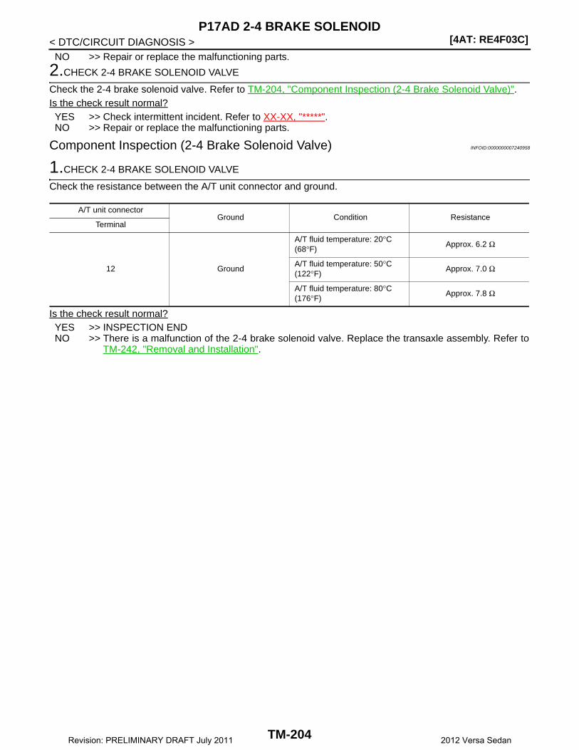
[4AT: RE4F03C]P17AD 2-4 BRAKE SOLENOID
< DTC/CIRCUIT DIAGNOSIS >NO >> Repair or replace the malfunctioning parts.
2.CHECK 2-4 BRAKE SOLENOID VALVE
Check the 2-4 brake solenoid valve. Refer to TM-204, "Component Inspection (2-4 Brake Solenoid Valve)".Is the check result normal?YES >> Check intermittent incident. Refer to XX-XX, "*****".NO >> Repair or replace the malfunctioning parts.
Component Inspection (2-4 Brake Solenoid Valve) INFOID:0000000007240958
1.CHECK 2-4 BRAKE SOLENOID VALVE
Check the resistance between the A/T unit connector and ground.
Is the check result normal?YES >> INSPECTION ENDNO >> There is a malfunction of the 2-4 brake solenoid valve. Replace the transaxle assembly. Refer to
TM-242, "Removal and Installation".
A/T unit connectorGround Condition Resistance
Terminal
12 Ground
A/T fluid temperature: 20°C (68°F)
Approx. 6.2 Ω
A/T fluid temperature: 50°C (122°F)
Approx. 7.0 Ω
A/T fluid temperature: 80°C (176°F)
Approx. 7.8 Ω
TM-204Revision: PRELIMINARY DRAFT July 2011 2012 Versa Sedan
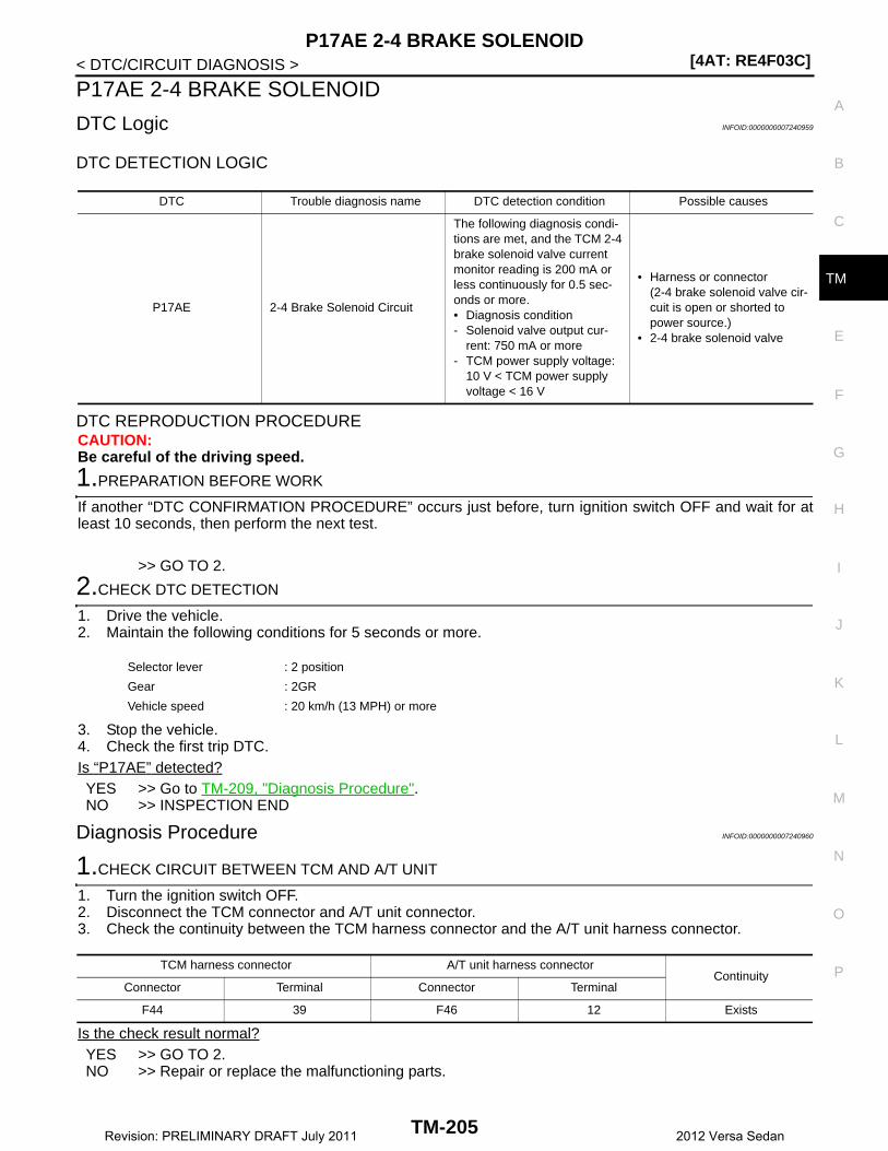
P17AE 2-4 BRAKE SOLENOID[4AT: RE4F03C]
C
E
F
G
H
I
J
K
L
M
A
B
M
N
O
P
< DTC/CIRCUIT DIAGNOSIS >
T
P17AE 2-4 BRAKE SOLENOID
DTC Logic INFOID:0000000007240959
DTC DETECTION LOGIC
DTC REPRODUCTION PROCEDURECAUTION:Be careful of the driving speed.
1.PREPARATION BEFORE WORK
If another “DTC CONFIRMATION PROCEDURE” occurs just before, turn ignition switch OFF and wait for atleast 10 seconds, then perform the next test.
>> GO TO 2.
2.CHECK DTC DETECTION
1. Drive the vehicle.2. Maintain the following conditions for 5 seconds or more.
3. Stop the vehicle.4. Check the first trip DTC.Is “P17AE” detected?YES >> Go to TM-209, "Diagnosis Procedure".NO >> INSPECTION END
Diagnosis Procedure INFOID:0000000007240960
1.CHECK CIRCUIT BETWEEN TCM AND A/T UNIT
1. Turn the ignition switch OFF.2. Disconnect the TCM connector and A/T unit connector.3. Check the continuity between the TCM harness connector and the A/T unit harness connector.
Is the check result normal?YES >> GO TO 2.NO >> Repair or replace the malfunctioning parts.
DTC Trouble diagnosis name DTC detection condition Possible causes
P17AE 2-4 Brake Solenoid Circuit
The following diagnosis condi-tions are met, and the TCM 2-4 brake solenoid valve current monitor reading is 200 mA or less continuously for 0.5 sec-onds or more.• Diagnosis condition- Solenoid valve output cur-
rent: 750 mA or more- TCM power supply voltage:
10 V < TCM power supply voltage < 16 V
• Harness or connector(2-4 brake solenoid valve cir-cuit is open or shorted to power source.)
• 2-4 brake solenoid valve
Selector lever : 2 position
Gear : 2GR
Vehicle speed : 20 km/h (13 MPH) or more
TCM harness connector A/T unit harness connectorContinuity
Connector Terminal Connector Terminal
F44 39 F46 12 Exists
TM-205Revision: PRELIMINARY DRAFT July 2011 2012 Versa Sedan
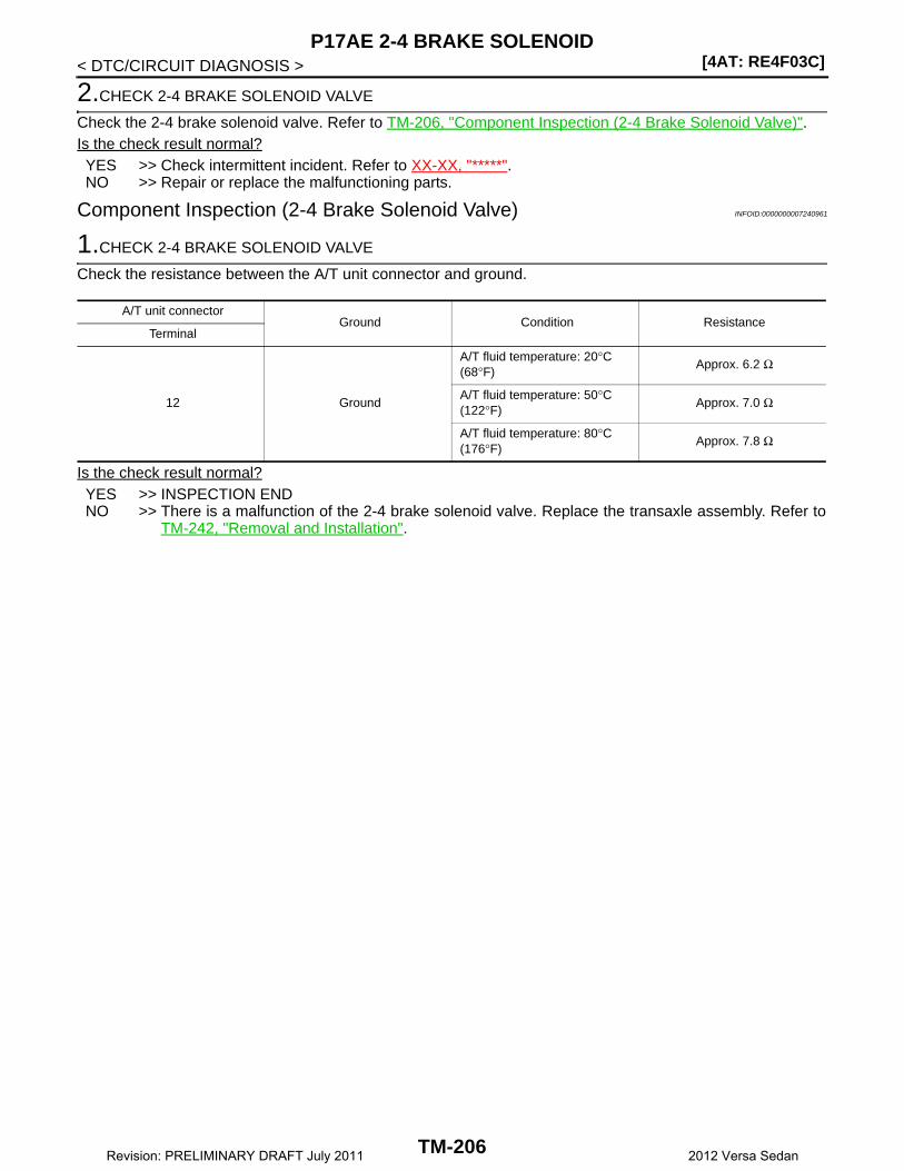
[4AT: RE4F03C]P17AE 2-4 BRAKE SOLENOID
< DTC/CIRCUIT DIAGNOSIS >
2.CHECK 2-4 BRAKE SOLENOID VALVE
Check the 2-4 brake solenoid valve. Refer to TM-206, "Component Inspection (2-4 Brake Solenoid Valve)".Is the check result normal?YES >> Check intermittent incident. Refer to XX-XX, "*****".NO >> Repair or replace the malfunctioning parts.
Component Inspection (2-4 Brake Solenoid Valve) INFOID:0000000007240961
1.CHECK 2-4 BRAKE SOLENOID VALVE
Check the resistance between the A/T unit connector and ground.
Is the check result normal?YES >> INSPECTION ENDNO >> There is a malfunction of the 2-4 brake solenoid valve. Replace the transaxle assembly. Refer to
TM-242, "Removal and Installation".
A/T unit connectorGround Condition Resistance
Terminal
12 Ground
A/T fluid temperature: 20°C (68°F)
Approx. 6.2 Ω
A/T fluid temperature: 50°C (122°F)
Approx. 7.0 Ω
A/T fluid temperature: 80°C (176°F)
Approx. 7.8 Ω
TM-206Revision: PRELIMINARY DRAFT July 2011 2012 Versa Sedan
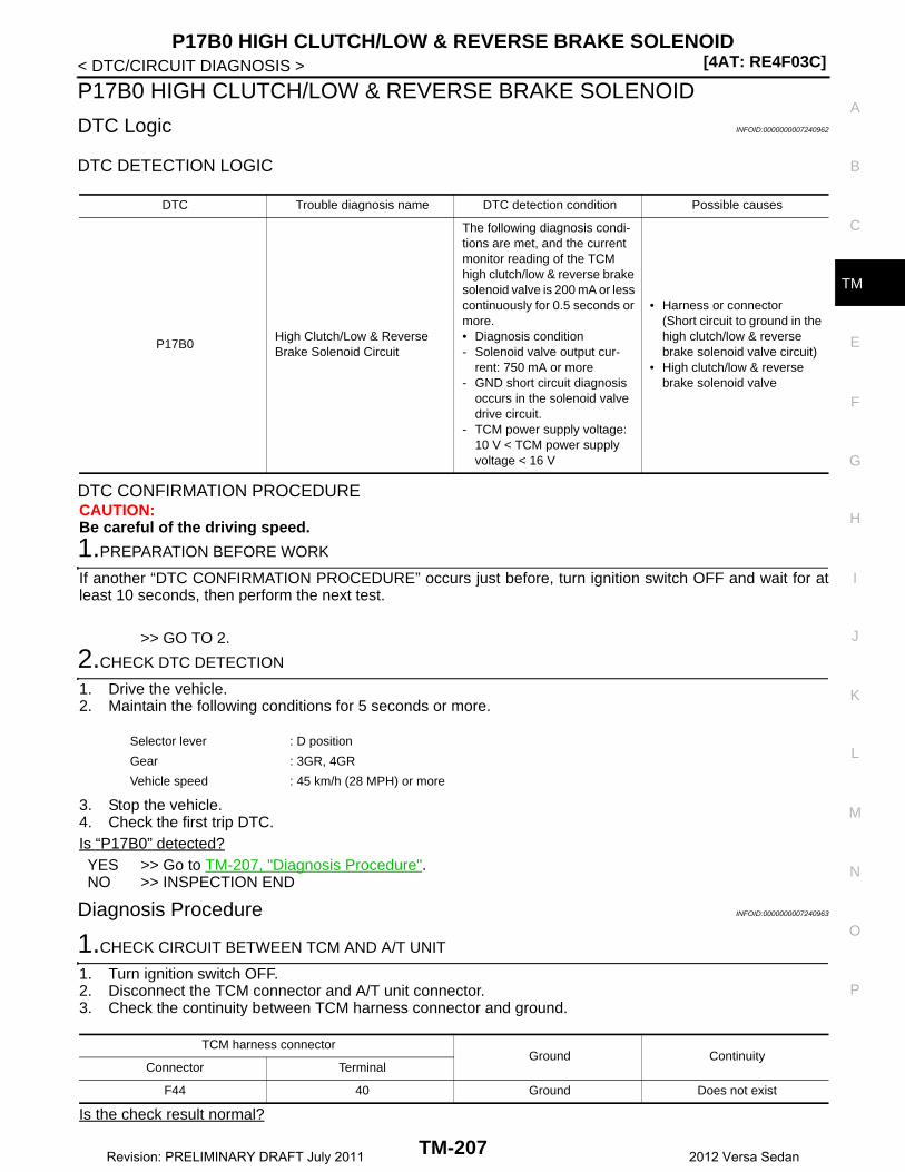
P17B0 HIGH CLUTCH/LOW & REVERSE BRAKE SOLENOID[4AT: RE4F03C]
C
E
F
G
H
I
J
K
L
M
A
B
M
N
O
P
< DTC/CIRCUIT DIAGNOSIS >
T
P17B0 HIGH CLUTCH/LOW & REVERSE BRAKE SOLENOID
DTC Logic INFOID:0000000007240962
DTC DETECTION LOGIC
DTC CONFIRMATION PROCEDURECAUTION:Be careful of the driving speed.
1.PREPARATION BEFORE WORK
If another “DTC CONFIRMATION PROCEDURE” occurs just before, turn ignition switch OFF and wait for atleast 10 seconds, then perform the next test.
>> GO TO 2.
2.CHECK DTC DETECTION
1. Drive the vehicle.2. Maintain the following conditions for 5 seconds or more.
3. Stop the vehicle.4. Check the first trip DTC.Is “P17B0” detected?YES >> Go to TM-207, "Diagnosis Procedure".NO >> INSPECTION END
Diagnosis Procedure INFOID:0000000007240963
1.CHECK CIRCUIT BETWEEN TCM AND A/T UNIT
1. Turn ignition switch OFF.2. Disconnect the TCM connector and A/T unit connector.3. Check the continuity between TCM harness connector and ground.
Is the check result normal?
DTC Trouble diagnosis name DTC detection condition Possible causes
P17B0High Clutch/Low & Reverse Brake Solenoid Circuit
The following diagnosis condi-tions are met, and the current monitor reading of the TCM high clutch/low & reverse brake solenoid valve is 200 mA or less continuously for 0.5 seconds or more.• Diagnosis condition- Solenoid valve output cur-
rent: 750 mA or more- GND short circuit diagnosis
occurs in the solenoid valve drive circuit.
- TCM power supply voltage: 10 V < TCM power supply voltage < 16 V
• Harness or connector(Short circuit to ground in the high clutch/low & reverse brake solenoid valve circuit)
• High clutch/low & reverse brake solenoid valve
Selector lever : D position
Gear : 3GR, 4GR
Vehicle speed : 45 km/h (28 MPH) or more
TCM harness connectorGround Continuity
Connector Terminal
F44 40 Ground Does not exist
TM-207Revision: PRELIMINARY DRAFT July 2011 2012 Versa Sedan
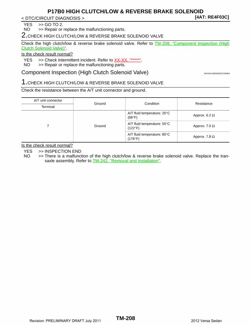
[4AT: RE4F03C]P17B0 HIGH CLUTCH/LOW & REVERSE BRAKE SOLENOID
< DTC/CIRCUIT DIAGNOSIS >YES >> GO TO 2.NO >> Repair or replace the malfunctioning parts.
2.CHECK HIGH CLUTCH/LOW & REVERSE BRAKE SOLENOID VALVE
Check the high clutch/low & reverse brake solenoid valve. Refer to TM-208, "Component Inspection (HighClutch Solenoid Valve)".Is the check result normal?YES >> Check intermittent incident. Refer to XX-XX, "*****".NO >> Repair or replace the malfunctioning parts.
Component Inspection (High Clutch Solenoid Valve) INFOID:0000000007240964
1.CHECK HIGH CLUTCH/LOW & REVERSE BRAKE SOLENOID VALVE
Check the resistance between the A/T unit connector and ground.
Is the check result normal?YES >> INSPECTION ENDNO >> There is a malfunction of the high clutch/low & reverse brake solenoid valve. Replace the tran-
saxle assembly. Refer to TM-242, "Removal and Installation".
A/T unit connectorGround Condition Resistance
Terminal
7 Ground
A/T fluid temperature: 20°C (68°F)
Approx. 6.2 Ω
A/T fluid temperature: 50°C (122°F)
Approx. 7.0 Ω
A/T fluid temperature: 80°C (176°F)
Approx. 7.8 Ω
TM-208Revision: PRELIMINARY DRAFT July 2011 2012 Versa Sedan
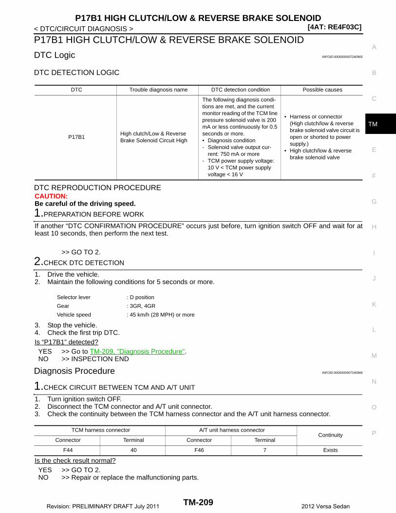
P17B1 HIGH CLUTCH/LOW & REVERSE BRAKE SOLENOID[4AT: RE4F03C]
C
E
F
G
H
I
J
K
L
M
A
B
M
N
O
P
< DTC/CIRCUIT DIAGNOSIS >
T
P17B1 HIGH CLUTCH/LOW & REVERSE BRAKE SOLENOID
DTC Logic INFOID:0000000007240965
DTC DETECTION LOGIC
DTC REPRODUCTION PROCEDURECAUTION:Be careful of the driving speed.
1.PREPARATION BEFORE WORK
If another “DTC CONFIRMATION PROCEDURE” occurs just before, turn ignition switch OFF and wait for atleast 10 seconds, then perform the next test.
>> GO TO 2.
2.CHECK DTC DETECTION
1. Drive the vehicle.2. Maintain the following conditions for 5 seconds or more.
3. Stop the vehicle.4. Check the first trip DTC.Is “P17B1” detected?YES >> Go to TM-209, "Diagnosis Procedure".NO >> INSPECTION END
Diagnosis Procedure INFOID:0000000007240966
1.CHECK CIRCUIT BETWEEN TCM AND A/T UNIT
1. Turn ignition switch OFF.2. Disconnect the TCM connector and A/T unit connector.3. Check the continuity between the TCM harness connector and the A/T unit harness connector.
Is the check result normal?YES >> GO TO 2.NO >> Repair or replace the malfunctioning parts.
DTC Trouble diagnosis name DTC detection condition Possible causes
P17B1High clutch/Low & Reverse Brake Solenoid Circuit High
The following diagnosis condi-tions are met, and the current monitor reading of the TCM line pressure solenoid valve is 200 mA or less continuously for 0.5 seconds or more.• Diagnosis condition- Solenoid valve output cur-
rent: 750 mA or more- TCM power supply voltage:
10 V < TCM power supply voltage < 16 V
• Harness or connector(High clutch/low & reverse brake solenoid valve circuit is open or shorted to power supply.)
• High clutch/low & reverse brake solenoid valve
Selector lever : D position
Gear : 3GR, 4GR
Vehicle speed : 45 km/h (28 MPH) or more
TCM harness connector A/T unit harness connectorContinuity
Connector Terminal Connector Terminal
F44 40 F46 7 Exists
TM-209Revision: PRELIMINARY DRAFT July 2011 2012 Versa Sedan

[4AT: RE4F03C]P17B1 HIGH CLUTCH/LOW & REVERSE BRAKE SOLENOID
< DTC/CIRCUIT DIAGNOSIS >
2.CHECK HIGH CLUTCH/LOW & REVERSE BRAKE SOLENOID VALVE
Check the high clutch/low & reverse brake solenoid valve. Refer to TM-210, "Component Inspection (HighClutch Solenoid Valve)".Is the check result normal?YES >> Check intermittent incident. Refer to XX-XX, "*****".NO >> Repair or replace the malfunctioning parts.
Component Inspection (High Clutch Solenoid Valve) INFOID:0000000007240967
1.CHECK HIGH CLUTCH/LOW & REVERSE BRAKE SOLENOID VALVE
Check the resistance between the A/T unit connector and ground.
Is the check result normal?YES >> INSPECTION ENDNO >> There is a malfunction of the high clutch/low & reverse brake solenoid valve. Replace the tran-
saxle assembly. Refer to TM-242, "Removal and Installation".
A/T unit connectorGround Condition Resistance
Terminal
7 Ground
A/T fluid temperature: 20°C (68°F)
Approx. 6.2 Ω
A/T fluid temperature: 50°C (122°F)
Approx. 7.0 Ω
A/T fluid temperature: 80°C (176°F)
Approx. 7.8 Ω
TM-210Revision: PRELIMINARY DRAFT July 2011 2012 Versa Sedan

MAIN POWER SUPPLY AND GROUND CIRCUIT[4AT: RE4F03C]
C
E
F
G
H
I
J
K
L
M
A
B
M
N
O
P
< DTC/CIRCUIT DIAGNOSIS >
T
MAIN POWER SUPPLY AND GROUND CIRCUIT
Diagnosis Procedure INFOID:0000000007240968
1.CHECK TCM POWER CIRCUIT 1
1. Turn the ignition switch OFF.2. Disconnect the TCM connector.3. Check the voltage between the TCM harness connector terminals and ground.
Is the inspection result normal?YES >> GO TO 2.NO >> GO TO 4.
2.CHECK TCM POWER CIRCUIT 2
Check the voltage between the TCM harness connector terminals and ground.
Is the inspection result normal?YES >> GO TO 3.NO >> GO TO 5.
3.CHECK TCM GROUND CIRCUIT
Check the continuity between TCM harness connector terminals and ground.
Is the inspection result normal?YES >> Check intermittent incident. Refer to XX-XX, "*****".NO >> Repair or replace the malfunctioning parts.
4.DETECT MALFUNCTION ITEMS (PART 1)
Check the following items:• Open or short circuit of the harness between battery positive terminal and TCM connectors terminal 45.• 10A fuse [No.25, fuse block (J/B)]. Refer to XX-XX, "*****".Is the inspection result normal?YES >> Check intermittent incident. Refer to XX-XX, "*****".NO >> Repair or replace the malfunctioning parts.
5.DETECT MALFUNCTION ITEMS (PART 2)
Check the following items:• Open or short circuit of the harness between IPDM E/R harness connector terminal 21 and TCM connector
terminals 47, 48.• Harness open circuit or short circuit between the ignition switch and IPDM E/R. Refer to XX-XX, "*****".• 10A fuse [No.49, IPDM E/R]. Refer to XX-XX, "*****".
TCM harness connectorGround Voltage
Connector Terminal
F44 45 Ground 10 − 16
TCM harness connectorGround Condition Voltage
Connector Terminal
F44
47
Ground
Ignition switch ON 10 − 16
Ignition switch OFF Approx. 0 V
48Ignition switch ON 10 − 16
Ignition switch OFF Approx. 0 V
TCM harness connectorGround Continuity
Connector Terminal
F4441
Ground Existed42
TM-211Revision: PRELIMINARY DRAFT July 2011 2012 Versa Sedan
[4AT: RE4F03C]MAIN POWER SUPPLY AND GROUND CIRCUIT
< DTC/CIRCUIT DIAGNOSIS >• IPDM E/RIs the inspection result normal?YES >> Check intermittent incident. Refer to XX-XX, "*****".NO >> Repair or replace the malfunctioning parts.
TM-212Revision: PRELIMINARY DRAFT July 2011 2012 Versa Sedan

OVERDRIVE CONTROL SWITCH[4AT: RE4F03C]
C
E
F
G
H
I
J
K
L
M
A
B
M
N
O
P
< DTC/CIRCUIT DIAGNOSIS >
T
OVERDRIVE CONTROL SWITCH
Component Function Check INFOID:0000000007240969
1.CHECK O/D INDICATOR LAMP FUNCTION
Check O/D OFF indicator lamp turns ON for approx. 2 seconds when ignition switch turns ON.Is the inspection results normal?YES >> GO TO 2.NO >> Go to TM-215, "Diagnosis Procedure".
2.CHECK O/D SWITCH FUNCTION
1. Shift the selector lever to “D” position.2. Check that O/D OFF indicator lamp turns ON/OFF when sport mode switch is operated.Is the inspection results normal?YES >> INSPECTION ENDNO >> Go to TM-213, "Diagnosis Procedure".
Diagnosis Procedure INFOID:0000000007240970
1.CHECK OVERDRIVE CONTROL SWITCH CIRCUIT
1. Turn ignition switch OFF.2. Disconnect A/T shift selector connector.3. Turn ignition switch ON.4. Check the voltage between A/T shift selector harness connector terminals.
Is the inspection result normal?YES >> GO TO 2.NO >> GO TO 3.
2.CHECK OVERDRIVE CONTROL SWITCH
Check overdrive control switch. Refer to TM-214, "Component Inspection (Overdrive Control Switch)".Is the inspection result normal?YES >> Check intermittent incident. Refer to XX-XX, "*****".NO >> Repair or replace the malfunctioning parts.
3.CHECK GROUND CIRCUIT
Check the continuity between A/T shift selector harness connector terminal and ground.
Is the inspection result normal?YES >> GO TO 4.NO >> Repair or replace the malfunctioning parts.
4.CHECK CIRCUIT BETWEEN COMBINATION METER AND A/T SHIFT SELECTOR (PART 1)
1. Turn ignition switch OFF.2. Disconnect combination meter connector.3. Check the continuity between combination meter harness connector terminal and A/T shift selector har-
ness connector terminal.
A/T shift selector harness connectorVoltage
Connector Terminal
M38 1 2 Approx. 5 V
A/T shift selector harness connectorGround Continuity
Connector Terminal
M38 2 Ground Existed
TM-213Revision: PRELIMINARY DRAFT July 2011 2012 Versa Sedan

[4AT: RE4F03C]OVERDRIVE CONTROL SWITCH
< DTC/CIRCUIT DIAGNOSIS >
Is the inspection result normal?YES >> GO TO 5.NO >> Repair or replace the malfunctioning parts.
5.CHECK CIRCUIT BETWEEN COMBINATION METER AND A/T SHIFT SELECTOR (PART 2)
Check the continuity between combination meter harness connector terminal and ground.
Is the inspection result normal?YES >> GO TO 6.NO >> Repair or replace the malfunctioning parts.
6.CHECK COMBINATION METER INPUT SIGNAL
1. Connect all of the disconnected connectors.2. Turn ignition switch ON.3. Select “Data Monitor” in “METER/M&A”.4. Select “O/D OFF SW”.5. Check that “O/D OFF SW” turns ON/OFF when overdrive control switch is operated. Refer to XX-XX,
"*****".Is the inspection result normal?YES >> Check intermittent incident. Refer to XX-XX, "*****".NO >> Replace combination meter. Refer to XX-XX, "*****".
Component Inspection (Overdrive Control Switch) INFOID:0000000007240971
1.CHECK OVERDRIVE CONTROL SWITCH
Check the continuity between wires of selector lever knob (1)
Is the inspection result normal?YES >> INSPECTION ENDNO >> Replace the selector lever knob. Refer to TM-227,
"Removal and Installation".
Combination meter harness connector A/T shift selector harness connectorContinuity
Type Connector Terminal Connector Terminal
A M82 8M38 1 Existed
B M24 28
Combination meter harness connectorGround Continuity
Type Connector Terminal
A M82 8Ground Not existed
B M24 28
Condition Continuity
Overdrive control switch is depressed Existed
Overdrive control switch is released Not existed
JSDIA1969ZZ
TM-214Revision: PRELIMINARY DRAFT July 2011 2012 Versa Sedan
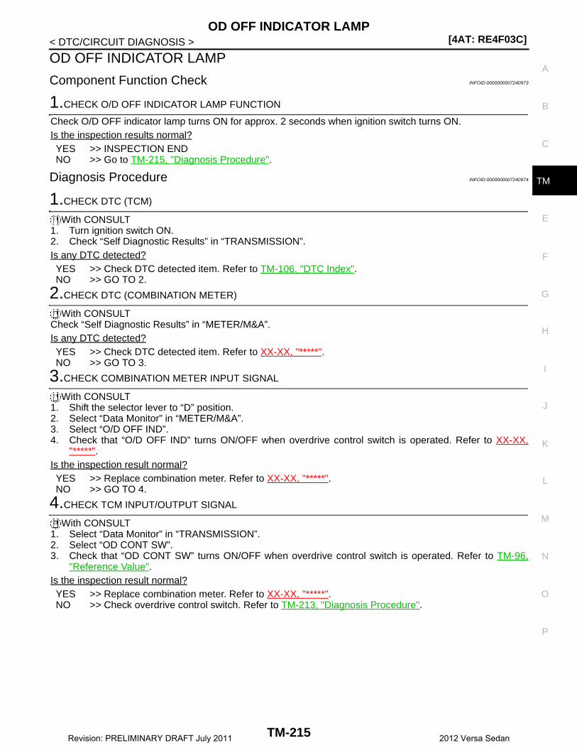
OD OFF INDICATOR LAMP[4AT: RE4F03C]
C
E
F
G
H
I
J
K
L
M
A
B
M
N
O
P
< DTC/CIRCUIT DIAGNOSIS >
T
OD OFF INDICATOR LAMP
Component Function Check INFOID:0000000007240973
1.CHECK O/D OFF INDICATOR LAMP FUNCTION
Check O/D OFF indicator lamp turns ON for approx. 2 seconds when ignition switch turns ON.Is the inspection results normal?YES >> INSPECTION ENDNO >> Go to TM-215, "Diagnosis Procedure".
Diagnosis Procedure INFOID:0000000007240974
1.CHECK DTC (TCM)
With CONSULT1. Turn ignition switch ON.2. Check “Self Diagnostic Results” in “TRANSMISSION”.Is any DTC detected?YES >> Check DTC detected item. Refer to TM-106, "DTC Index".NO >> GO TO 2.
2.CHECK DTC (COMBINATION METER)
With CONSULTCheck “Self Diagnostic Results” in “METER/M&A”.Is any DTC detected?YES >> Check DTC detected item. Refer to XX-XX, "*****".NO >> GO TO 3.
3.CHECK COMBINATION METER INPUT SIGNAL
With CONSULT1. Shift the selector lever to “D” position.2. Select “Data Monitor” in “METER/M&A”.3. Select “O/D OFF IND”.4. Check that “O/D OFF IND” turns ON/OFF when overdrive control switch is operated. Refer to XX-XX,
"*****".Is the inspection result normal?YES >> Replace combination meter. Refer to XX-XX, "*****".NO >> GO TO 4.
4.CHECK TCM INPUT/OUTPUT SIGNAL
With CONSULT1. Select “Data Monitor” in “TRANSMISSION”.2. Select “OD CONT SW”.3. Check that “OD CONT SW” turns ON/OFF when overdrive control switch is operated. Refer to TM-96,
"Reference Value".Is the inspection result normal?YES >> Replace combination meter. Refer to XX-XX, "*****".NO >> Check overdrive control switch. Refer to TM-213, "Diagnosis Procedure".
TM-215Revision: PRELIMINARY DRAFT July 2011 2012 Versa Sedan

[4AT: RE4F03C]SHIFT POSITION INDICATOR CIRCUIT
< DTC/CIRCUIT DIAGNOSIS >
SHIFT POSITION INDICATOR CIRCUIT
Component Parts Function Inspection INFOID:0000000007240975
1.CHECK SHIFT POSITION INDICATOR
1. Start the engine.2. Shift the selector lever.3. Check that the selector lever position and the shift position indicator on the combination meter are identi-
cal.Is the inspection result normal?YES >> INSPECTION ENDNO >> Go to TM-216, "Diagnosis Procedure".
Diagnosis Procedure INFOID:0000000007240976
1.CHECK TCM INPUT/OUTPUT SIGNAL
With CONSULT1. Start the engine.2. Select “Data Monitor” in “TRANSMISSION”.3. Select “RANGE”. 4. Shift the selector lever.5. Check that selector lever position, “RANGE” on the CONSULT screen, and shift position indicator display
on the combination meter are identical. Is the check result normal?YES >> INSPECTION ENDNO-1 (“RANGE” is changed but is not displayed on the shift position indicator.>>Check “Self Diagnostic
Result” in “TRANSMISSION”.NO-2 (“RANGE” and shift position indicator are different.)>>Check “Self Diagnostic Result” in “TRANSMIS-
SION”.NO-3 (Specific“RANGE” is not displayed on the shift position indicator.)>>Check “Self Diagnostic Result” in
“METER/M&A”.
TM-216Revision: PRELIMINARY DRAFT July 2011 2012 Versa Sedan
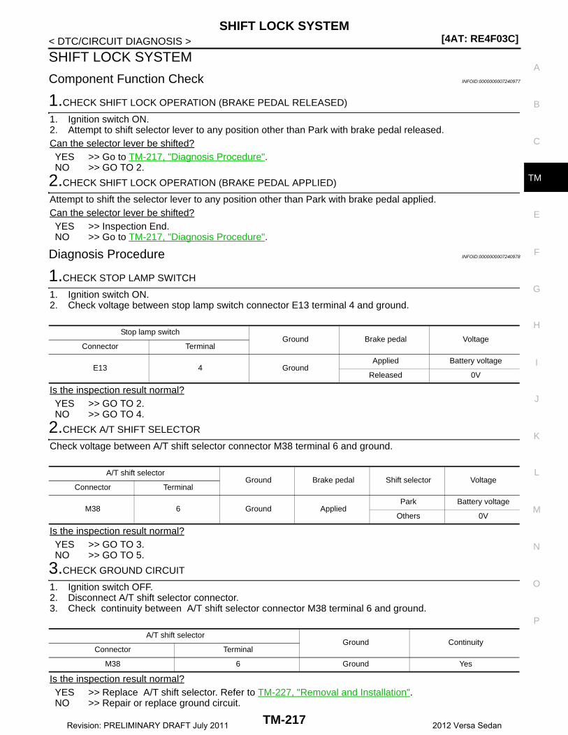
SHIFT LOCK SYSTEM[4AT: RE4F03C]
C
E
F
G
H
I
J
K
L
M
A
B
M
N
O
P
< DTC/CIRCUIT DIAGNOSIS >
T
SHIFT LOCK SYSTEM
Component Function Check INFOID:0000000007240977
1.CHECK SHIFT LOCK OPERATION (BRAKE PEDAL RELEASED)
1. Ignition switch ON.2. Attempt to shift selector lever to any position other than Park with brake pedal released.Can the selector lever be shifted?YES >> Go to TM-217, "Diagnosis Procedure".NO >> GO TO 2.
2.CHECK SHIFT LOCK OPERATION (BRAKE PEDAL APPLIED)
Attempt to shift the selector lever to any position other than Park with brake pedal applied.Can the selector lever be shifted?YES >> Inspection End.NO >> Go to TM-217, "Diagnosis Procedure".
Diagnosis Procedure INFOID:0000000007240978
1.CHECK STOP LAMP SWITCH
1. Ignition switch ON.2. Check voltage between stop lamp switch connector E13 terminal 4 and ground.
Is the inspection result normal?YES >> GO TO 2.NO >> GO TO 4.
2.CHECK A/T SHIFT SELECTOR
Check voltage between A/T shift selector connector M38 terminal 6 and ground.
Is the inspection result normal?YES >> GO TO 3.NO >> GO TO 5.
3.CHECK GROUND CIRCUIT
1. Ignition switch OFF.2. Disconnect A/T shift selector connector.3. Check continuity between A/T shift selector connector M38 terminal 6 and ground.
Is the inspection result normal?YES >> Replace A/T shift selector. Refer to TM-227, "Removal and Installation".NO >> Repair or replace ground circuit.
Stop lamp switchGround Brake pedal Voltage
Connector Terminal
E13 4 GroundApplied Battery voltage
Released 0V
A/T shift selectorGround Brake pedal Shift selector Voltage
Connector Terminal
M38 6 Ground AppliedPark Battery voltage
Others 0V
A/T shift selectorGround Continuity
Connector Terminal
M38 6 Ground Yes
TM-217Revision: PRELIMINARY DRAFT July 2011 2012 Versa Sedan

[4AT: RE4F03C]SHIFT LOCK SYSTEM
< DTC/CIRCUIT DIAGNOSIS >
4.CHECK STOP LAMP SWITCH POWER CIRCUIT
Check voltage between stop lamp switch connector E13 terminal 3 and ground.
Is the inspection result normal?YES >> Replace stop lamp switch.NO >> Repair or replace power circuit.
5.CHECK A/T SHIFT SELECTOR POWER CIRCUIT
Check voltage between A/T shift selector connector M38 terminal 5 and ground.
Is the inspection result normal?YES >> Replace A/T shift selector. Refer to TM-227, "Removal and Installation".NO >> Repair or replace power circuit.
Stop lamp switchGround Voltage
Connector Terminal
E13 3 Ground Battery voltage
A/T shift selectorGround Brake pedal Voltage
Connector Terminal
M38 5 Ground Applied Battery voltage
TM-218Revision: PRELIMINARY DRAFT July 2011 2012 Versa Sedan
SYSTEM SYMPTOM[4AT: RE4F03C]
C
E
F
G
H
I
J
K
L
M
A
B
M
N
O
P
< SYMPTOM DIAGNOSIS >
T
SYMPTOM DIAGNOSISSYSTEM SYMPTOM
Symptom Table INFOID:0000000007240983
The diagnosis item numbers show the sequence for inspection. Inspect in order from item 1.CAUTION:If any malfunction occurs in the RE4F03C transmission, replace the transaxle assembly.
TM-219Revision: PRELIMINARY DRAFT July 2011 2012 Versa Sedan
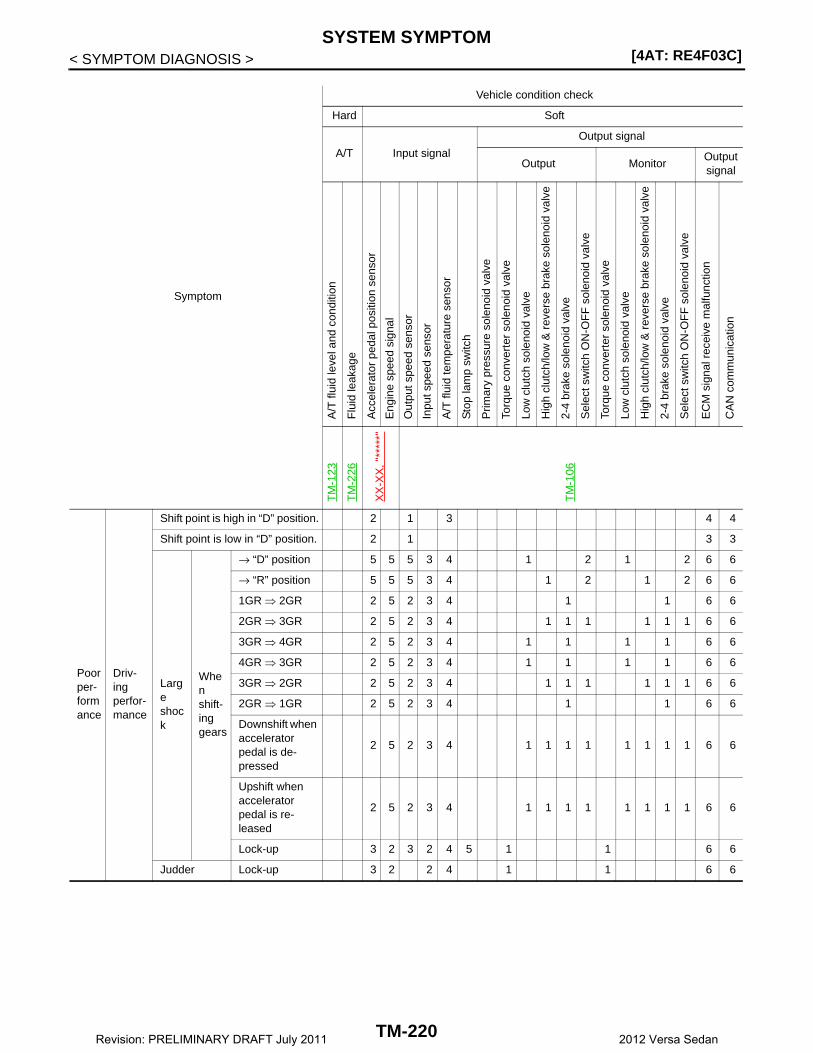
[4AT: RE4F03C]SYSTEM SYMPTOM
< SYMPTOM DIAGNOSIS >
Symptom
Vehicle condition check
Hard Soft
A/T Input signal
Output signal
Output MonitorOutput signal
A/T
flui
d le
vel a
nd c
ondi
tion
Flu
id le
akag
e
Acc
eler
ator
ped
al p
ositi
on s
enso
r
Eng
ine
spee
d si
gnal
Out
put s
peed
sen
sor
Inpu
t spe
ed s
enso
r
A/T
flui
d te
mpe
ratu
re s
enso
r
Sto
p la
mp
switc
h
Prim
ary
pres
sure
sol
enoi
d va
lve
Torq
ue c
onve
rter
sol
enoi
d va
lve
Low
clu
tch
sole
noid
val
ve
Hig
h cl
utch
/low
& r
ever
se b
rake
sol
enoi
d va
lve
2-4
brak
e so
leno
id v
alve
Sel
ect s
witc
h O
N-O
FF
sol
enoi
d va
lve
Torq
ue c
onve
rter
sol
enoi
d va
lve
Low
clu
tch
sole
noid
val
ve
Hig
h cl
utch
/low
& r
ever
se b
rake
sol
enoi
d va
lve
2-4
brak
e so
leno
id v
alve
Sel
ect s
witc
h O
N-O
FF
sol
enoi
d va
lve
EC
M s
igna
l rec
eive
mal
func
tion
CA
N c
omm
unic
atio
n
TM
-123
TM
-226
XX
-XX
, "**
***"
TM
-106
Poor per-formance
Driv-ing perfor-mance
Shift point is high in “D” position. 2 1 3 4 4
Shift point is low in “D” position. 2 1 3 3
Large shock
When shift-ing gears
→ “D” position 5 5 5 3 4 1 2 1 2 6 6
→ “R” position 5 5 5 3 4 1 2 1 2 6 6
1GR ⇒ 2GR 2 5 2 3 4 1 1 6 6
2GR ⇒ 3GR 2 5 2 3 4 1 1 1 1 1 1 6 6
3GR ⇒ 4GR 2 5 2 3 4 1 1 1 1 6 6
4GR ⇒ 3GR 2 5 2 3 4 1 1 1 1 6 6
3GR ⇒ 2GR 2 5 2 3 4 1 1 1 1 1 1 6 6
2GR ⇒ 1GR 2 5 2 3 4 1 1 6 6
Downshift when accelerator pedal is de-pressed
2 5 2 3 4 1 1 1 1 1 1 1 1 6 6
Upshift when accelerator pedal is re-leased
2 5 2 3 4 1 1 1 1 1 1 1 1 6 6
Lock-up 3 2 3 2 4 5 1 1 6 6
Judder Lock-up 3 2 2 4 1 1 6 6
TM-220Revision: PRELIMINARY DRAFT July 2011 2012 Versa Sedan

SYSTEM SYMPTOM[4AT: RE4F03C]
C
E
F
G
H
I
J
K
L
M
A
B
M
N
O
P
< SYMPTOM DIAGNOSIS >
T
Poor per-formance
Strange noise
In “R” position 1 2 3 3 3 3 3
In “N” position 1 2 3 3 3 3 3
In “D” position 1 2 3 3 3 3 3
Noise
Engine at idle 1 2 3 3 3 3 3
In “D”, “R” posi-tions
1 2 3 3 3 3 3
Fluid leakage 1
Symptom
Vehicle condition check
Hard Soft
A/T Input signal
Output signal
Output MonitorOutput signal
A/T
flui
d le
vel a
nd c
ondi
tion
Flu
id le
akag
e
Acc
eler
ator
ped
al p
ositi
on s
enso
r
Eng
ine
spee
d si
gnal
Out
put s
peed
sen
sor
Inpu
t spe
ed s
enso
r
A/T
flui
d te
mpe
ratu
re s
enso
r
Sto
p la
mp
switc
h
Prim
ary
pres
sure
sol
enoi
d va
lve
Torq
ue c
onve
rter
sol
enoi
d va
lve
Low
clu
tch
sole
noid
val
ve
Hig
h cl
utch
/low
& r
ever
se b
rake
sol
enoi
d va
lve
2-4
brak
e so
leno
id v
alve
Sel
ect s
witc
h O
N-O
FF
sol
enoi
d va
lve
Torq
ue c
onve
rter
sol
enoi
d va
lve
Low
clu
tch
sole
noid
val
ve
Hig
h cl
utch
/low
& r
ever
se b
rake
sol
enoi
d va
lve
2-4
brak
e so
leno
id v
alve
Sel
ect s
witc
h O
N-O
FF
sol
enoi
d va
lve
EC
M s
igna
l rec
eive
mal
func
tion
CA
N c
omm
unic
atio
n
TM
-123
TM
-226
XX
-XX
, "**
***"
TM
-106
TM-221Revision: PRELIMINARY DRAFT July 2011 2012 Versa Sedan

[4AT: RE4F03C]SYSTEM SYMPTOM
< SYMPTOM DIAGNOSIS >
Symptom
Vehicle condition check
Hard Soft
A/T Input signal
Output signal
Output/monitorOutput signal
A/T
flui
d le
vel a
nd c
ondi
tion
Line
pre
ssur
e
Acc
eler
ator
ped
al p
ositi
on s
enso
r
Eng
ine
spee
d si
gnal
Out
put s
peed
sen
sor
Inpu
t spe
ed s
enso
r
A/T
flui
d te
mpe
ratu
re s
enso
r
Sto
p la
mp
switc
h
Prim
ary
pres
sure
sol
enoi
d va
lve
Torq
ue c
onve
rter
sol
enoi
d va
lve
Low
clu
tch
sole
noid
val
ve
Hig
h cl
utch
/low
& r
ever
se b
rake
sol
enoi
d va
lve
2-4
brak
e so
leno
id v
alve
Sel
ect s
witc
h O
N-O
FF
sol
enoi
d va
lve
EC
M s
igna
l rec
eive
mal
func
tion
CA
N c
omm
unic
atio
n
TM
-123
TM
-126
XX
-XX
, "**
***"
TM
-106
Func-tion trouble
Gear does not change
“D” po-sition
Locks in 1GR
Locks in 2GR 1 1 1
Locks in 3GR 1 1 1 1 1 1 1
Locks in 4GR
1GR → 2GR 2 1
2GR → 3GR 1 1 1
3GR → 4GR 1 1
4GR → 3GR 2 1 1
3GR → 2GR 1 1 1
2GR → 1GR 1
Does not lock-up 4 3 4 3 5 2 1 6 6
Poor shifting
SlipWhen shifting gears
1GR ⇔ 2GR 2 4 4 4 5 1 1 3 3
2GR ⇔ 3GR 2 4 4 4 5 1 1 1 3 3
3GR ⇔ 4GR 2 4 4 4 5 1 1 1 3 3
TM-222Revision: PRELIMINARY DRAFT July 2011 2012 Versa Sedan
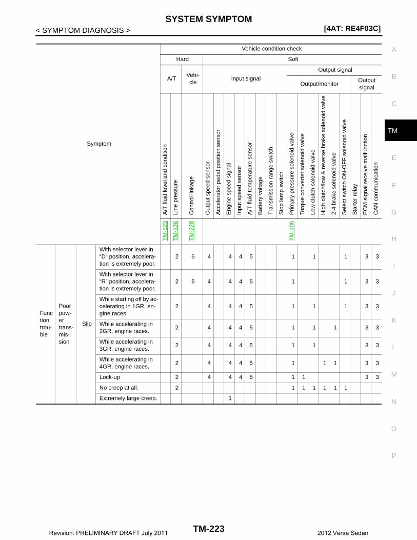
SYSTEM SYMPTOM[4AT: RE4F03C]
C
E
F
G
H
I
J
K
L
M
A
B
M
N
O
P
< SYMPTOM DIAGNOSIS >
T
Symptom
Vehicle condition check
Hard Soft
A/TVehi-cle
Input signal
Output signal
Output/monitorOutput signal
A/T
flui
d le
vel a
nd c
ondi
tion
Line
pre
ssur
e
Con
trol
link
age
Out
put s
peed
sen
sor
Acc
eler
ator
ped
al p
ositi
on s
enso
r
Eng
ine
spee
d si
gnal
Inpu
t spe
ed s
enso
r
A/T
flui
d te
mpe
ratu
re s
enso
r
Bat
tery
vol
tage
Tran
smis
sion
ran
ge s
witc
h
Sto
p la
mp
switc
h
Prim
ary
pres
sure
sol
enoi
d va
lve
Torq
ue c
onve
rter
sol
enoi
d va
lve
Low
clu
tch
sole
noid
val
ve
Hig
h cl
utch
/low
& r
ever
se b
rake
sol
enoi
d va
lve
2-4
brak
e so
leno
id v
alve
Sel
ect s
witc
h O
N-O
FF
sol
enoi
d va
lve
Sta
rter
rel
ay
EC
M s
igna
l rec
eive
mal
func
tion
CA
N c
omm
unic
atio
n
TM
-123
TM
-126
TM
-228
TM
-106
Function trou-ble
Poor pow-er trans-mis-sion
Slip
With selector lever in “D” position, accelera-tion is extremely poor.
2 6 4 4 4 5 1 1 1 3 3
With selector lever in “R” position, accelera-tion is extremely poor.
2 6 4 4 4 5 1 1 3 3
While starting off by ac-celerating in 1GR, en-gine races.
2 4 4 4 5 1 1 1 3 3
While accelerating in 2GR, engine races.
2 4 4 4 5 1 1 1 3 3
While accelerating in 3GR, engine races.
2 4 4 4 5 1 1 3 3
While accelerating in 4GR, engine races.
2 4 4 4 5 1 1 1 3 3
Lock-up 2 4 4 4 5 1 1 3 3
No creep at all. 2 1 1 1 1 1 1
Extremely large creep. 1
TM-223Revision: PRELIMINARY DRAFT July 2011 2012 Versa Sedan

[4AT: RE4F03C]SYSTEM SYMPTOM
< SYMPTOM DIAGNOSIS >
Function trou-ble
Power trans-mission can-not be performed
Vehicle cannot run in all position.
3 4 2 1 1 1 1 1
Driving is not possible in “D” position.
3 4 2 1 1 1 1 1
Driving is not possible in “R” position.
3 4 2 1 1
Engine does not start in “N” or “P” position.
2 1 3 4 5
Engine starts in posi-tion other than “N” or “P”.
1 2 3 4
Engine stall 3 4 4 5 2 1 1 1 1 1
Engine stalls when se-lector lever shifted “N” → “D” or “R”.
3 4 4 1 1
Symptom
Vehicle condition check
Hard Soft
A/TVehi-cle
Input signal
Output signal
Output/monitorOutput signal
A/T
flui
d le
vel a
nd c
ondi
tion
Line
pre
ssur
e
Con
trol
link
age
Out
put s
peed
sen
sor
Acc
eler
ator
ped
al p
ositi
on s
enso
r
Eng
ine
spee
d si
gnal
Inpu
t spe
ed s
enso
r
A/T
flui
d te
mpe
ratu
re s
enso
r
Bat
tery
vol
tage
Tran
smis
sion
ran
ge s
witc
h
Sto
p la
mp
switc
h
Prim
ary
pres
sure
sol
enoi
d va
lve
Torq
ue c
onve
rter
sol
enoi
d va
lve
Low
clu
tch
sole
noid
val
ve
Hig
h cl
utch
/low
& r
ever
se b
rake
sol
enoi
d va
lve
2-4
brak
e so
leno
id v
alve
Sel
ect s
witc
h O
N-O
FF
sol
enoi
d va
lve
Sta
rter
rel
ay
EC
M s
igna
l rec
eive
mal
func
tion
CA
N c
omm
unic
atio
n
TM
-123
TM
-126
TM
-228
TM
-106
TM-224Revision: PRELIMINARY DRAFT July 2011 2012 Versa Sedan
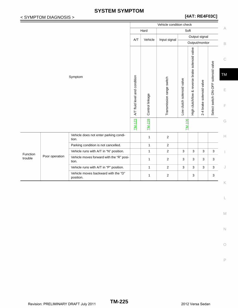
SYSTEM SYMPTOM[4AT: RE4F03C]
C
E
F
G
H
I
J
K
L
M
A
B
M
N
O
P
< SYMPTOM DIAGNOSIS >
TSymptom
Vehicle condition check
Hard Soft
A/T Vehicle Input signalOutput signal
Output/monitor
A/T
flui
d le
vel a
nd c
ondi
tion
Con
trol
link
age
Tran
smis
sion
ran
ge s
witc
h
Low
clu
tch
sole
noid
val
ve
Hig
h cl
utch
/low
& r
ever
se b
rake
sol
enoi
d va
lve
2-4
brak
e so
leno
id v
alve
Sel
ect s
witc
h O
N-O
FF
sol
enoi
d va
lve
TM
-123
TM
-228
TM
-106
Function trouble
Poor operation
Vehicle does not enter parking condi-tion.
1 2
Parking condition is not cancelled. 1 2
Vehicle runs with A/T in “N” position. 1 2 3 3 3 3
Vehicle moves forward with the “R” posi-tion.
1 2 3 3 3 3
Vehicle runs with A/T in “P” position. 1 2 3 3 3 3
Vehicle moves backward with the “D” position.
1 2 3 3
TM-225Revision: PRELIMINARY DRAFT July 2011 2012 Versa Sedan
[4AT: RE4F03C]A/T FLUID
< PERIODIC MAINTENANCE >
PERIODIC MAINTENANCEA/T FLUID
Inspection INFOID:0000000007240984
FLUID LEAKAGE• Check transaxle surrounding area (oil seal and plug etc.)for fluid
leakage.• If anything is found, repair or replace damaged parts and adjust A/
T fluid level. Refer to TM-123, "Adjustment".
SMA146B
TM-226Revision: PRELIMINARY DRAFT July 2011 2012 Versa Sedan
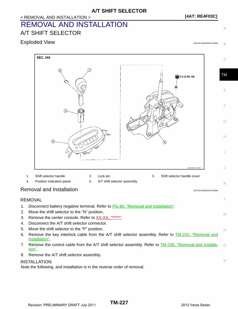
A/T SHIFT SELECTOR[4AT: RE4F03C]
C
E
F
G
H
I
J
K
L
M
A
B
M
N
O
P
< REMOVAL AND INSTALLATION >
T
REMOVAL AND INSTALLATIONA/T SHIFT SELECTOR
Exploded View INFOID:0000000007240985
Removal and Installation INFOID:0000000007240986
REMOVAL1. Disconnect battery negative terminal. Refer to PG-84, "Removal and Installation".2. Move the shift selector to the “N” position.3. Remove the center console. Refer to XX-XX, "*****".4. Disconnect the A/T shift selector connector.5. Move the shift selector to the “P” position. 6. Remove the key interlock cable from the A/T shift selector assembly. Refer to TM-232, "Removal and
Installation".7. Remove the control cable from the A/T shift selector assembly. Refer to TM-230, "Removal and Installa-
tion".8. Remove the A/T shift selector assembly.
INSTALLATIONNote the following, and installation is in the reverse order of removal.
1. Shift selector handle 2. Lock pin 3. Shift selector handle cover
4. Position indication panel 5. A/T shift selector assembly
ALDIA0263GB
TM-227Revision: PRELIMINARY DRAFT July 2011 2012 Versa Sedan

[4AT: RE4F03C]A/T SHIFT SELECTOR
< REMOVAL AND INSTALLATION >• When connecting the control cable (1) to the A/T shift selector
assembly (2), face the grooved surface of the rib (A) up and insertthe control cable until it stops.
Disassembly and Assembly INFOID:0000000007240987
DISASSEMBLY1. Slide the shift selector handle cover (1) down.
CAUTION:Do not damage the shift selector handle cover.
2. Pull out the lock pin (2).3. Pull the shift selector handle (3) and shift selector handle cover
upwards to remove them.4. Remove the position lamp.
5. Disengage the hooks (A) (4 locations), and lift up the positionindication panel (1) to separate it from the A/T shift selectorassembly (2).CAUTION:Do not damage the A/T shift selector assembly.
ASSEMBLYNote the following, and assembly is in the reverse order of disassembly.• Follow the procedure below and place the shift selector handle onto the A/T shift selector.1. Install the lock pin (2) onto the shift selector handle (3).2. Install the shift selector handle cover (1) onto the shift selector
handle.3. Press the shift selector handle onto the shift selector until it
clicks.CAUTION:• When pressing the shift selector handle onto the shift
selector, never press the shift selector handle button.• Never strike the shift selector handle to press it into place.
4. After installing shift selector handle, pull the handle to check thatit does not become disconnected.
Inspection and Adjustment INFOID:0000000007240840
INSPECTION
JSDIA1624ZZ
JSDIA1796ZZ
ALDIA0264ZZ
JSDIA1796ZZ
TM-228Revision: PRELIMINARY DRAFT July 2011 2012 Versa Sedan
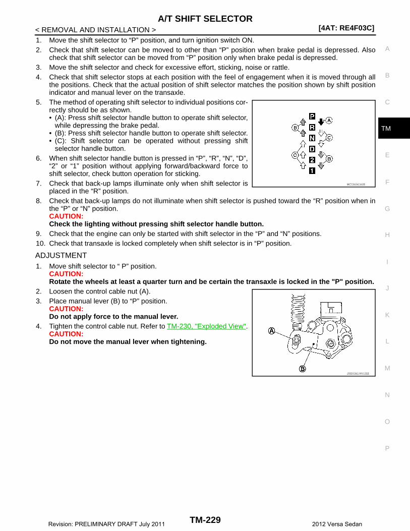
A/T SHIFT SELECTOR[4AT: RE4F03C]
C
E
F
G
H
I
J
K
L
M
A
B
M
N
O
P
< REMOVAL AND INSTALLATION >
T
1. Move the shift selector to “P” position, and turn ignition switch ON.2. Check that shift selector can be moved to other than “P” position when brake pedal is depressed. Also
check that shift selector can be moved from “P” position only when brake pedal is depressed.3. Move the shift selector and check for excessive effort, sticking, noise or rattle.4. Check that shift selector stops at each position with the feel of engagement when it is moved through all
the positions. Check that the actual position of shift selector matches the position shown by shift positionindicator and manual lever on the transaxle.
5. The method of operating shift selector to individual positions cor-rectly should be as shown.• (A): Press shift selector handle button to operate shift selector,
while depressing the brake pedal.• (B): Press shift selector handle button to operate shift selector.• (C): Shift selector can be operated without pressing shift
selector handle button.6. When shift selector handle button is pressed in “P”, “R”, “N”, “D”,
“2” or “1” position without applying forward/backward force toshift selector, check button operation for sticking.
7. Check that back-up lamps illuminate only when shift selector isplaced in the “R” position.
8. Check that back-up lamps do not illuminate when shift selector is pushed toward the “R” position when inthe “P” or “N” position.CAUTION:Check the lighting without pressing shift selector handle button.
9. Check that the engine can only be started with shift selector in the “P” and “N” positions.10. Check that transaxle is locked completely when shift selector is in “P” position.
ADJUSTMENT1. Move shift selector to “ P” position.
CAUTION:Rotate the wheels at least a quarter turn and be certain the transaxle is locked in the "P" position.
2. Loosen the control cable nut (A).3. Place manual lever (B) to “P” position.
CAUTION:Do not apply force to the manual lever.
4. Tighten the control cable nut. Refer to TM-230, "Exploded View".CAUTION:Do not move the manual lever when tightening.
WCIA0636E
JSDIA1951ZZ
TM-229Revision: PRELIMINARY DRAFT July 2011 2012 Versa Sedan

[4AT: RE4F03C]CONTROL CABLE
< REMOVAL AND INSTALLATION >
CONTROL CABLE
Exploded View INFOID:0000000007240989
Removal and Installation INFOID:0000000007240990
REMOVALCAUTION:Always apply the parking brake before performing removal and installation.1. Remove the air cleaner case. Refer to EM-24, "Removal and Installation".2. Remove the control cable from the A/T shift selector assembly.3. Disengage the pawls (B) of the grommet (A), and pull down-
wards to remove.4. Remove the control cable nut from the manual lever.
5. Remove the lock plate (1).
1. Bracket B 2. Lock plate 3. Transaxle assembly
4. Bracket A 5. Control cable 6. A/T shift selector assembly
A: Manual lever B: Grommet
JSDIA1921GB
JSDIA1809ZZ
JSDIA1812ZZ
TM-230Revision: PRELIMINARY DRAFT July 2011 2012 Versa Sedan
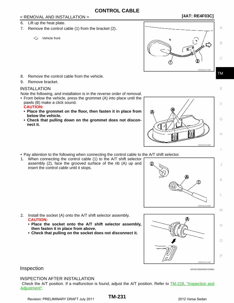
CONTROL CABLE[4AT: RE4F03C]
C
E
F
G
H
I
J
K
L
M
A
B
M
N
O
P
< REMOVAL AND INSTALLATION >
T
6. Lift up the heat plate.7. Remove the control cable (1) from the bracket (2).
8. Remove the control cable from the vehicle.9. Remove bracket.
INSTALLATIONNote the following, and installation is in the reverse order of removal.• From below the vehicle, press the grommet (A) into place until the
pawls (B) make a click sound.CAUTION:• Place the grommet on the floor, then fasten it in place from
below the vehicle.• Check that pulling down on the grommet does not discon-
nect it.
• Pay attention to the following when connecting the control cable to the A/T shift selector.1. When connecting the control cable (1) to the A/T shift selector
assembly (2), face the grooved surface of the rib (A) up andinsert the control cable until it stops.
2. Install the socket (A) onto the A/T shift selector assembly.CAUTION:• Place the socket onto the A/T shift selector assembly,
then fasten it in place from above.• Check that pulling on the socket does not disconnect it.
Inspection INFOID:0000000007240991
INSPECTION AFTER INSTALLATION Check the A/T position. If a malfunction is found, adjust the A/T position. Refer to TM-228, "Inspection andAdjustment".
:Vehicle front
JPDIA0107ZZ
JSDIA1809ZZ
JSDIA1624ZZ
JSDIA1810ZZ
TM-231Revision: PRELIMINARY DRAFT July 2011 2012 Versa Sedan
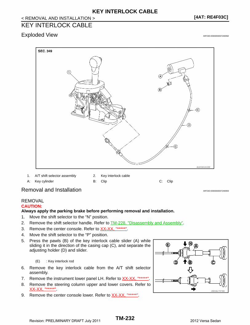
[4AT: RE4F03C]KEY INTERLOCK CABLE
< REMOVAL AND INSTALLATION >
KEY INTERLOCK CABLE
Exploded View INFOID:0000000007240992
Removal and Installation INFOID:0000000007240993
REMOVALCAUTION:Always apply the parking brake before performing removal and installation.1. Move the shift selector to the “N” position.2. Remove the shift selector handle. Refer to TM-228, "Disassembly and Assembly".3. Remove the center console. Refer to XX-XX, "*****".4. Move the shift selector to the “P” position.5. Press the pawls (B) of the key interlock cable slider (A) while
sliding it in the direction of the casing cap (C), and separate theadjusting holder (D) and slider.
6. Remove the key interlock cable from the A/T shift selectorassembly.
7. Remove the instrument lower panel LH. Refer to XX-XX, "*****".8. Remove the steering column upper and lower covers. Refer to
XX-XX, "*****".9. Remove the center console lower. Refer to XX-XX, "*****".
1. A/T shift selector assembly 2. Key interlock cable
A: Key cylinder B: Clip C: Clip
ALDIA0262ZZ
(E) : Key interlock rod
JSDIA1797ZZ
TM-232Revision: PRELIMINARY DRAFT July 2011 2012 Versa Sedan

KEY INTERLOCK CABLE[4AT: RE4F03C]
C
E
F
G
H
I
J
K
L
M
A
B
M
N
O
P
< REMOVAL AND INSTALLATION >
T
10. Lift clip (A) in the direction of the arrow ( C) and remove in thedirection of the arrow ( D).
11. Remove the key interlock cable from the key cylinder.12. Disengage the clip and remove the key interlock cable from the
vehicle.
INSTALLATIONNote the following, and installation is in the reverse order of removal.• Install the adjusting holder (A) onto the key interlock rod (B), then
install the casing cap (C) onto the A/T shift selector assembly (D).CAUTION:• When installing the key interlock cable, never bend or twist
the cable forcefully.• After connecting the key interlock cable to the A/T shift
selector assembly, be sure to check that the casing cap iscompletely fastened to the A/T shift selector assembly. If thecasing cap is easily displaced, replace the key interlockcable.
• While pressing the detent rod (B) down, slide the key interlockcable slider (A) toward the key interlock rod (D) side, and install theadjusting holder (C) and key interlock rod.CAUTION:• Do not squeeze the pawls on the key interlock cable slider
when holding the slider.• Make sure key interlock rod is aligned with the slider during
installation.
Inspection INFOID:0000000007240994
INSPECTION AFTER INSTALLATION• Check the A/T position. If a malfunction is found, adjust the A/T position. Refer to TM-228, "Inspection and
Adjustment".• The key can be removed only when the shift selector is in the “P” position.• It must not be possible to turn the ignition switch to LOCK when the shift selector is not in the “P” position.
(1) : Key interlock cable
(B) : Key cylinder
JSDIA1798ZZ
JSDIA1799ZZ
JSDIA1800ZZ
TM-233Revision: PRELIMINARY DRAFT July 2011 2012 Versa Sedan
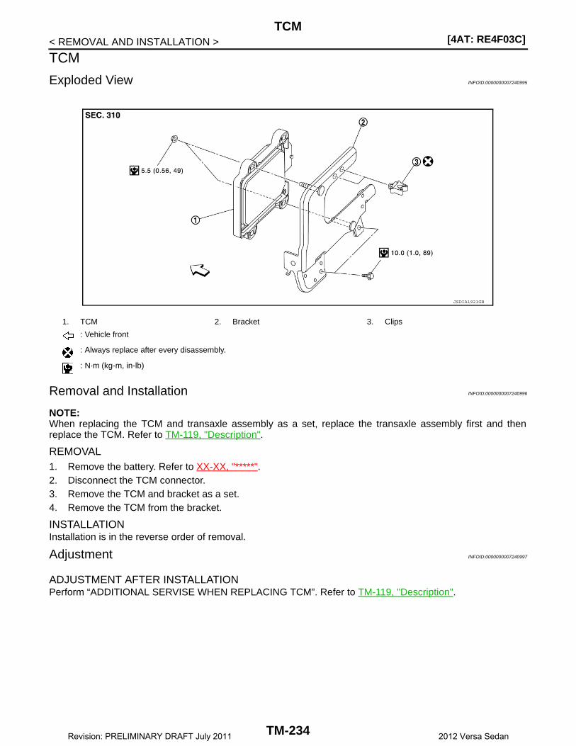
[4AT: RE4F03C]TCM
< REMOVAL AND INSTALLATION >
TCM
Exploded View INFOID:0000000007240995
Removal and Installation INFOID:0000000007240996
NOTE:When replacing the TCM and transaxle assembly as a set, replace the transaxle assembly first and thenreplace the TCM. Refer to TM-119, "Description".
REMOVAL1. Remove the battery. Refer to XX-XX, "*****".2. Disconnect the TCM connector.3. Remove the TCM and bracket as a set.4. Remove the TCM from the bracket.
INSTALLATIONInstallation is in the reverse order of removal.
Adjustment INFOID:0000000007240997
ADJUSTMENT AFTER INSTALLATIONPerform “ADDITIONAL SERVISE WHEN REPLACING TCM”. Refer to TM-119, "Description".
1. TCM 2. Bracket 3. Clips
: Vehicle front
: Always replace after every disassembly.
: N·m (kg-m, in-lb)
JSDIA1923GB
TM-234Revision: PRELIMINARY DRAFT July 2011 2012 Versa Sedan

OIL PAN[4AT: RE4F03C]
C
E
F
G
H
I
J
K
L
M
A
B
M
N
O
P
< REMOVAL AND INSTALLATION >
T
OIL PAN
Exploded View INFOID:0000000007240998
Removal and Installation INFOID:0000000007240999
REMOVAL1. Remove the drain plug and overflow tube, and then drain the ATF.
CAUTION:A/T fluid can splash when draining, use safety glasses to protect eyes.
2. Remove the drain plug gasket from the drain plug.
3. Remove the oil pan bolts ( ), and then remove the oil pan andoil pan gasket.
4. Remove the magnets from the oil pan.
1. Transaxle assembly 2. Oil pan gasket 3. Magnet
4. Oil pan 5. Overflow tube 6. Drain plug gasket
7. Drain plug 8. Oil pan fitting bolt
: Always replace after every disassembly.
: N·m (kg-m, ft-lb)
: N·m (kg-m, in-lb)
JSDIA1932GB
:Vehicle front
JSDIA1933ZZ
TM-235Revision: PRELIMINARY DRAFT July 2011 2012 Versa Sedan

[4AT: RE4F03C]OIL PAN
< REMOVAL AND INSTALLATION >
INSTALLATIONNote the following, and installation is in the reverse order of removal.CAUTION:• Do not reuse oil pan gasket and drain plug gasket.• Do not reuse oil pan bolts.• Completely remove any moisture, oil, old gasket, or other substances from the oil pan gasket mount-
ing surface.• When installing the overflow tube, be sure to tighten to the specified torque. If it is not tightened to
the specified torque, the tube may be damaged.• When the oil pan is installed, temporarily tighten oil pan bolts, then
tighten the oil pan bolts to specification in the order shown.
Inspection and Adjustment INFOID:0000000007241000
INSPECTION AFTER REMOVALCheck oil pan for foreign material.• If a large amount of worn material is found, clutch plate may be worn. • If iron powder is found, bearings, gears, or clutch plates may be worn.• If aluminum powder is found, bushing may be worn, or chips or burrs of aluminum casting parts may enter.Check points where wear is found in all cases.
INSPECTION AFTER INSTALLATIONCheck for A/T fluid leakage. Refer to TM-226, "Inspection".
ADJUSTMENT AFTER INSTALLATIONCheck the A/T fluid level. Refer to TM-123, "Adjustment".
:Vehicle front
JSDIA1934ZZ
TM-236Revision: PRELIMINARY DRAFT July 2011 2012 Versa Sedan

OUTPUT SPEED SENSOR[4AT: RE4F03C]
C
E
F
G
H
I
J
K
L
M
A
B
M
N
O
P
< REMOVAL AND INSTALLATION >
T
OUTPUT SPEED SENSOR
Exploded View INFOID:0000000007241001
Removal and Installation INFOID:0000000007241002
REMOVAL1. Remove the front LH wheel and tire. Refer to WT-6, "Removal and Installation".2. Disconnect the output speed sensor connector. 3. Remove the output speed sensor. 4. Remove the O-ring from the output speed sensor.
INSTALLATIONInstallation is in the reverse order of removal.CAUTION:• Do not reuse O-ring.• Apply Genuine NISSAN Matic S ATF to the O-ring.
Inspection and Adjustment INFOID:0000000007241003
INSPECTION AFTER INSTALLATIONCheck for A/T fluid leakage. Refer to TM-226, "Inspection".
ADJUSTMENT AFTER INSTALLATIONCheck the A/T fluid level. Refer to TM-123, "Adjustment".
1. Output speed sensor 2. O-ring 3. Transaxle assembly
: Vehicle front
: Always replace after every disassembly.
: N·m (kg-m, in-lb)
: Genuine NISSAN Matic S ATF
JSDIA1935GB
TM-237Revision: PRELIMINARY DRAFT July 2011 2012 Versa Sedan
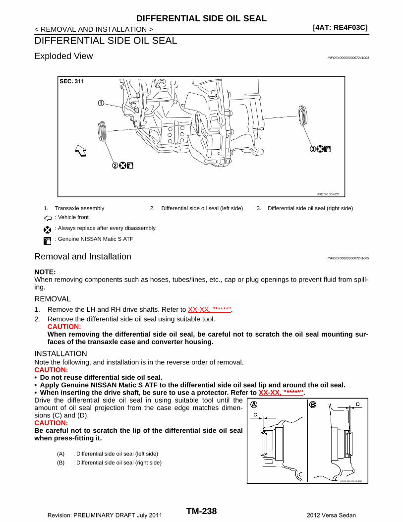
[4AT: RE4F03C]DIFFERENTIAL SIDE OIL SEAL
< REMOVAL AND INSTALLATION >
DIFFERENTIAL SIDE OIL SEAL
Exploded View INFOID:0000000007241004
Removal and Installation INFOID:0000000007241005
NOTE:When removing components such as hoses, tubes/lines, etc., cap or plug openings to prevent fluid from spill-ing.
REMOVAL1. Remove the LH and RH drive shafts. Refer to XX-XX, "*****".2. Remove the differential side oil seal using suitable tool.
CAUTION:When removing the differential side oil seal, be careful not to scratch the oil seal mounting sur-faces of the transaxle case and converter housing.
INSTALLATIONNote the following, and installation is in the reverse order of removal.CAUTION:• Do not reuse differential side oil seal.• Apply Genuine NISSAN Matic S ATF to the differential side oil seal lip and around the oil seal.• When inserting the drive shaft, be sure to use a protector. Refer to XX-XX, "*****".Drive the differential side oil seal in using suitable tool until theamount of oil seal projection from the case edge matches dimen-sions (C) and (D).CAUTION:Be careful not to scratch the lip of the differential side oil sealwhen press-fitting it.
1. Transaxle assembly 2. Differential side oil seal (left side) 3. Differential side oil seal (right side)
: Vehicle front
: Always replace after every disassembly.
: Genuine NISSAN Matic S ATF
JSDIA1936ZZ
(A) : Differential side oil seal (left side)
(B) : Differential side oil seal (right side)
JSDIA1836ZZ
TM-238Revision: PRELIMINARY DRAFT July 2011 2012 Versa Sedan
DIFFERENTIAL SIDE OIL SEAL[4AT: RE4F03C]
C
E
F
G
H
I
J
K
L
M
A
B
M
N
O
P
< REMOVAL AND INSTALLATION >
T
NOTE:
The reference is the pull-in direction of the differential side oil seal.
Drift to be used:
Inspection and Adjustment INFOID:0000000007241006
INSPECTION AFTER INSTALLATIONCheck for A/T fluid leakage. Refer to TM-226, "Inspection".
ADJUSTMENT AFTER INSTALLATIONCheck the A/T fluid level. Refer to TM-123, "Adjustment".
Dimension (C) : Height difference from case end surface is within 1.8 ± 0.5 mm (0.071 ± 0.020 in).
Dimension (D) : Height difference from case end surface is within 1.8 ± 0.5 mm (0.071 ± 0.020 in).
Location Commercial Service Tools
Transaxle case side Commercial service tool with outer dia. 56 mm (2.20 in) and in-ner dia. 50 mm (1.97 in)Converter housing side
TM-239Revision: PRELIMINARY DRAFT July 2011 2012 Versa Sedan
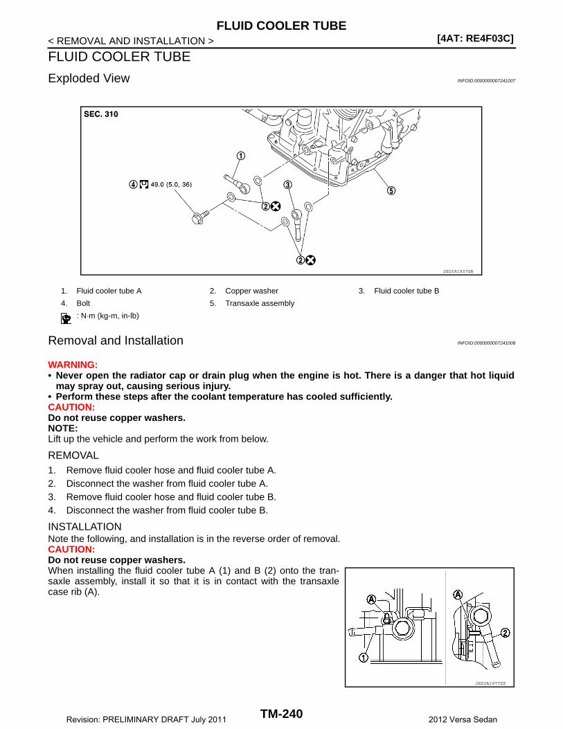
[4AT: RE4F03C]FLUID COOLER TUBE
< REMOVAL AND INSTALLATION >
FLUID COOLER TUBE
Exploded View INFOID:0000000007241007
Removal and Installation INFOID:0000000007241008
WARNING:• Never open the radiator cap or drain plug when the engine is hot. There is a danger that hot liquid
may spray out, causing serious injury.• Perform these steps after the coolant temperature has cooled sufficiently.CAUTION:Do not reuse copper washers.NOTE:Lift up the vehicle and perform the work from below.
REMOVAL1. Remove fluid cooler hose and fluid cooler tube A.2. Disconnect the washer from fluid cooler tube A. 3. Remove fluid cooler hose and fluid cooler tube B.4. Disconnect the washer from fluid cooler tube B.
INSTALLATIONNote the following, and installation is in the reverse order of removal.CAUTION:Do not reuse copper washers. When installing the fluid cooler tube A (1) and B (2) onto the tran-saxle assembly, install it so that it is in contact with the transaxlecase rib (A).
1. Fluid cooler tube A 2. Copper washer 3. Fluid cooler tube B
4. Bolt 5. Transaxle assembly
: N·m (kg-m, in-lb)
JSDIA1937GB
JSDIA1977ZZ
TM-240Revision: PRELIMINARY DRAFT July 2011 2012 Versa Sedan

FLUID COOLER TUBE[4AT: RE4F03C]
C
E
F
G
H
I
J
K
L
M
A
B
M
N
O
P
< REMOVAL AND INSTALLATION >
T
Inspection and Adjustment INFOID:0000000007241009
INSPECTION AFTER INSTALLATIONCheck for A/T fluid leakage. Refer to TM-226, "Inspection".
ADJUSTMENT AFTER INSTALLATIONCheck the A/T fluid level. Refer to TM-123, "Adjustment".
TM-241Revision: PRELIMINARY DRAFT July 2011 2012 Versa Sedan
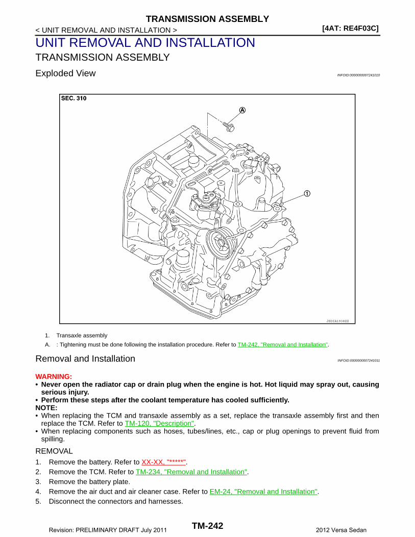
[4AT: RE4F03C]TRANSMISSION ASSEMBLY
< UNIT REMOVAL AND INSTALLATION >
UNIT REMOVAL AND INSTALLATIONTRANSMISSION ASSEMBLY
Exploded View INFOID:0000000007241010
Removal and Installation INFOID:0000000007241011
WARNING:• Never open the radiator cap or drain plug when the engine is hot. Hot liquid may spray out, causing
serious injury.• Perform these steps after the coolant temperature has cooled sufficiently.NOTE:• When replacing the TCM and transaxle assembly as a set, replace the transaxle assembly first and then
replace the TCM. Refer to TM-120, "Description".• When replacing components such as hoses, tubes/lines, etc., cap or plug openings to prevent fluid from
spilling.
REMOVAL1. Remove the battery. Refer to XX-XX, "*****".2. Remove the TCM. Refer to TM-234, "Removal and Installation".3. Remove the battery plate.4. Remove the air duct and air cleaner case. Refer to EM-24, "Removal and Installation".5. Disconnect the connectors and harnesses.
1. Transaxle assembly
A. : Tightening must be done following the installation procedure. Refer to TM-242, "Removal and Installation".
JSDIA1938ZZ
TM-242Revision: PRELIMINARY DRAFT July 2011 2012 Versa Sedan
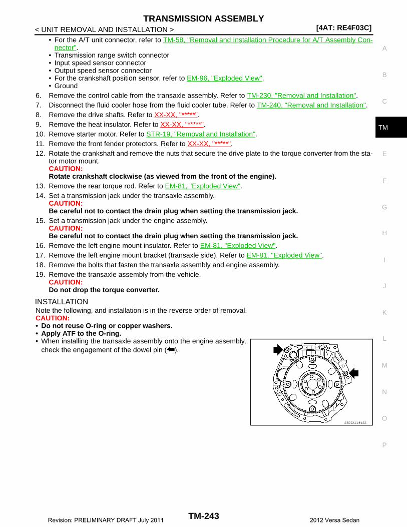
TRANSMISSION ASSEMBLY[4AT: RE4F03C]
C
E
F
G
H
I
J
K
L
M
A
B
M
N
O
P
< UNIT REMOVAL AND INSTALLATION >
T
• For the A/T unit connector, refer to TM-58, "Removal and Installation Procedure for A/T Assembly Con-nector".
• Transmission range switch connector• Input speed sensor connector• Output speed sensor connector• For the crankshaft position sensor, refer to EM-96, "Exploded View".• Ground
6. Remove the control cable from the transaxle assembly. Refer to TM-230, "Removal and Installation".7. Disconnect the fluid cooler hose from the fluid cooler tube. Refer to TM-240, "Removal and Installation".8. Remove the drive shafts. Refer to XX-XX, "*****".9. Remove the heat insulator. Refer to XX-XX, "*****".10. Remove starter motor. Refer to STR-19, "Removal and Installation".11. Remove the front fender protectors. Refer to XX-XX, "*****".12. Rotate the crankshaft and remove the nuts that secure the drive plate to the torque converter from the sta-
tor motor mount.CAUTION:Rotate crankshaft clockwise (as viewed from the front of the engine).
13. Remove the rear torque rod. Refer to EM-81, "Exploded View".14. Set a transmission jack under the transaxle assembly.
CAUTION:Be careful not to contact the drain plug when setting the transmission jack.
15. Set a transmission jack under the engine assembly.CAUTION:Be careful not to contact the drain plug when setting the transmission jack.
16. Remove the left engine mount insulator. Refer to EM-81, "Exploded View".17. Remove the left engine mount bracket (transaxle side). Refer to EM-81, "Exploded View".18. Remove the bolts that fasten the transaxle assembly and engine assembly.19. Remove the transaxle assembly from the vehicle.
CAUTION:Do not drop the torque converter.
INSTALLATIONNote the following, and installation is in the reverse order of removal.CAUTION:• Do not reuse O-ring or copper washers. • Apply ATF to the O-ring.• When installing the transaxle assembly onto the engine assembly,
check the engagement of the dowel pin ( ).
JSDIA1184ZZ
TM-243Revision: PRELIMINARY DRAFT July 2011 2012 Versa Sedan

[4AT: RE4F03C]TRANSMISSION ASSEMBLY
< UNIT REMOVAL AND INSTALLATION >• When using drive plate location guide, install suitable tool (A) to
drive plate location guide mounting location of torque converter.
• Rotate the crankshaft so that the drive plate location guide inserthole (A) of the drive plate is aligned with the drive plate locationguide that is installed on the torque converter.CAUTION:• Rotate the crankshaft clockwise (as viewed from the front of
the engine).• Be careful that torque converter stud bolt is aligned to drive
plate hole position. Otherwise stud bolt contacts drive plate.• Temporally tighten drive plate and torque converter connecting
nuts and tighten to the specified torque.
CAUTION:• Rotate crankshaft clockwise (as viewed from the front of the engine).• Check the tightening torque for the crankshaft pulley bolts after the bolts fastening the drive plate
and torque converter have been tightened and the crankshaft pulley bolts have been secured.Refer to EM-96, "Exploded View".
• Install the transaxle assembly and engine assembly bolts accord-ing to the following standards.
Inspection and Adjustment INFOID:0000000007241012
INSPECTION BEFORE INSTALLATION
JPDIA0683ZZ
Tightening torque : 51.5 N·m (5.3 kg-m, 38 ft-lb)JPDIA0684ZZ
JSDIA1839ZZ
Bolt No. A B C D
Direction of insertionTransaxle assembly →
Engine assemblyEngine assembly → Transaxle assembly
Number of bolts 2 2 1 3
Bolt length mm (in) 40 (1.57) 44 (1.73) 69 (2.72) 49 (1.93)
Tightening torqueN·m (kg-m, ft-lb)
48.0 (4.9, 35)
TM-244Revision: PRELIMINARY DRAFT July 2011 2012 Versa Sedan

TRANSMISSION ASSEMBLY[4AT: RE4F03C]
C
E
F
G
H
I
J
K
L
M
A
B
M
N
O
P
< UNIT REMOVAL AND INSTALLATION >
T
Check the distance “A” between the converter housing and torqueconverter.
INSPECTION AFTER INSTALLATIONCheck the following items:• A/T fluid leakage, refer to TM-226, "Inspection".• For the A/T positions, refer to TM-228, "Inspection and Adjustment"• Start the engine and check for coolant leakage from the parts which are removed and reinstalled.
ADJUSTMENT AFTER INSTALLATION• Check the A/T fluid level. Refer to TM-123, "Adjustment".• Perform “TRANSAXLE ASSEMBLY REPLACEMEN”. Refer to TM-120, "Description".
B : Scale
C : Straightedge
Dimension “A” : XX-XX, "*****"
JSDIA1840ZZ
TM-245Revision: PRELIMINARY DRAFT July 2011 2012 Versa Sedan
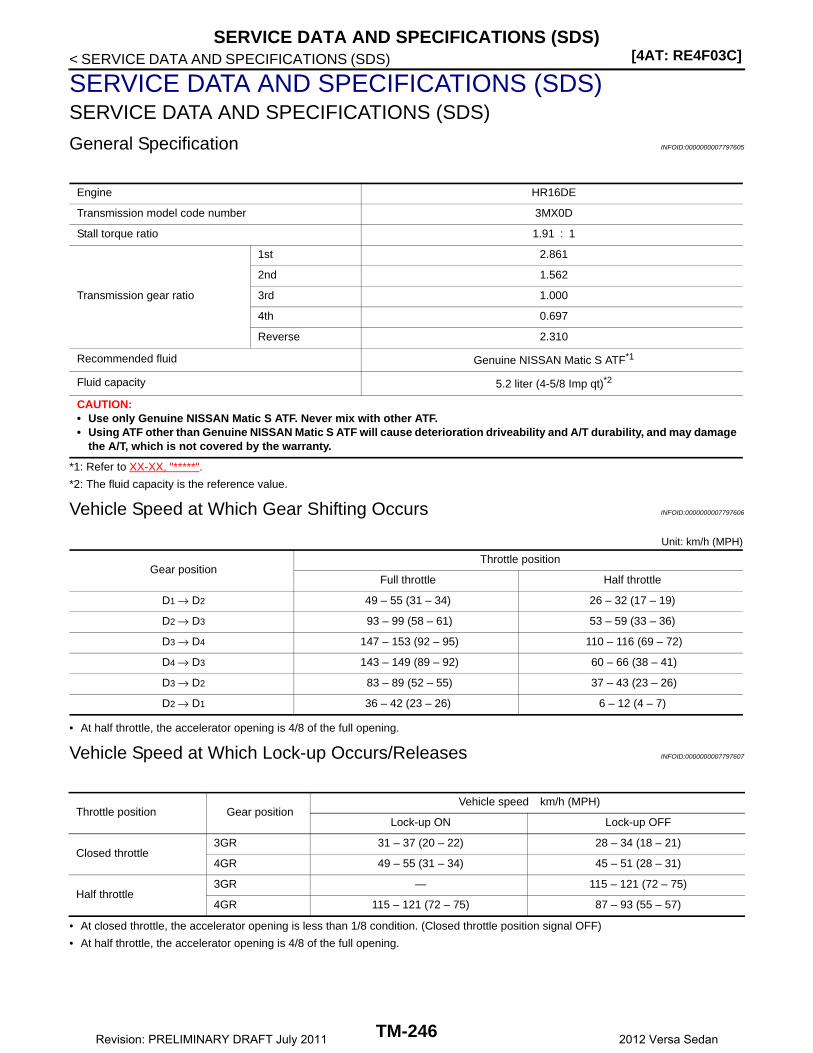
[4AT: RE4F03C]SERVICE DATA AND SPECIFICATIONS (SDS)
< SERVICE DATA AND SPECIFICATIONS (SDS)
SERVICE DATA AND SPECIFICATIONS (SDS)SERVICE DATA AND SPECIFICATIONS (SDS)
General Specification INFOID:0000000007797605
*1: Refer to XX-XX, "*****".
*2: The fluid capacity is the reference value.
Vehicle Speed at Which Gear Shifting Occurs INFOID:0000000007797606
Unit: km/h (MPH)
• At half throttle, the accelerator opening is 4/8 of the full opening.
Vehicle Speed at Which Lock-up Occurs/Releases INFOID:0000000007797607
• At closed throttle, the accelerator opening is less than 1/8 condition. (Closed throttle position signal OFF)
• At half throttle, the accelerator opening is 4/8 of the full opening.
Engine HR16DE
Transmission model code number 3MX0D
Stall torque ratio 1.91 : 1
Transmission gear ratio
1st 2.861
2nd 1.562
3rd 1.000
4th 0.697
Reverse 2.310
Recommended fluid Genuine NISSAN Matic S ATF*1
Fluid capacity 5.2 liter (4-5/8 Imp qt)*2
CAUTION:• Use only Genuine NISSAN Matic S ATF. Never mix with other ATF.• Using ATF other than Genuine NISSAN Matic S ATF will cause deterioration driveability and A/T durability, and may damage
the A/T, which is not covered by the warranty.
Gear positionThrottle position
Full throttle Half throttle
D1 → D2 49 – 55 (31 – 34) 26 – 32 (17 – 19)
D2 → D3 93 – 99 (58 – 61) 53 – 59 (33 – 36)
D3 → D4 147 – 153 (92 – 95) 110 – 116 (69 – 72)
D4 → D3 143 – 149 (89 – 92) 60 – 66 (38 – 41)
D3 → D2 83 – 89 (52 – 55) 37 – 43 (23 – 26)
D2 → D1 36 – 42 (23 – 26) 6 – 12 (4 – 7)
Throttle position Gear positionVehicle speed km/h (MPH)
Lock-up ON Lock-up OFF
Closed throttle3GR 31 – 37 (20 – 22) 28 – 34 (18 – 21)
4GR 49 – 55 (31 – 34) 45 – 51 (28 – 31)
Half throttle3GR — 115 – 121 (72 – 75)
4GR 115 – 121 (72 – 75) 87 – 93 (55 – 57)
TM-246Revision: PRELIMINARY DRAFT July 2011 2012 Versa Sedan

SERVICE DATA AND SPECIFICATIONS (SDS)[4AT: RE4F03C]
C
E
F
G
H
I
J
K
L
M
A
B
M
N
O
P
< SERVICE DATA AND SPECIFICATIONS (SDS)
T
Stall Speed INFOID:0000000007797608
Line Pressure INFOID:0000000007797609
Unit: kPa (bar, kg/cm2, psi)
Torque Converter INFOID:0000000007797610
Stall speed 2,410 – 2,850 rpm
Select position Engine speed Line pressure
“R” positionIdle speed 570 (5.7, 5.81, 82.7)
Stall speed 2,140 (21.4, 21.83, 310.3)
“D” positionIdle speed 410 (4.1, 4.18, 59.5)
Stall speed 1,400 (14.0, 14.28, 203.0)
Dimension between end of converter housing and torque converter 16.2 mm (0.638 in)
TM-247Revision: PRELIMINARY DRAFT July 2011 2012 Versa Sedan