translation of the original document of dibt by fischer
TRANSCRIPT

Approval number:
Date: Reference:
19.01.2021 I 25-1.21.8-74/20
Validity
Z-21.8-2057 from: 4 December 2020
to: 4 December 2025
Applicant:
fischerwerke GmbH & Co. KG
Klaus-Fischer-Straße 1
72178 Waldachtal
Subject of approval:
fischer insulation support 'DHM' in concrete
The subject of approval named above is herewith granted a national technical approval (allgemeine
bauaufsichtliche Zulassung).
This national technical document contains seven pages and three annexes.
The subject of approval was first granted a national technical approval on 3 December 2015.
The original document in German is always the Valid Document. This translation is only for
better communication
Translation of the original document of DIBt by fischer Engineers Teams

Translation by fischer Engineers team
National technical approval
(allgemeine bauaufsichtliche Zulassung)
No. Z-21.8-2057
Page 2 of 7 | 19. January 2021
I GENERAL PROVISIONS
1 With the national technical approval (allgemeine bauaufsichtliche Zulassung) the fitness for use and applicability of the subject of approval in accordance with the Building Codes of the federal states (Landesbauordnungen) have been verified.
2 If in the national technical approval requirements are made concerning the special expertise
and experience of persons entrusted with the manufacture of construction products and types of construction in accordance with the provisions of the relevant federal state following Section 17 Sub-section 5 of the Model Building Code (Musterbauordnung), it shall be noted that this expertise and experience can also be proven by equivalent verifications from other Member States of the European Union. If necessary, this also applies to equivalent verifications presented within the framework of the Agreement on the European Economic Area (EEA) or other bilateral agreements.
3 The national technical approval does not replace the permits, approvals and certificates
prescribed by law for carrying out building projects.
4 The national technical approval is granted without prejudice to the rights of third parties, in
particular private property rights.
5 Notwithstanding further provisions in the 'Special Provisions', manufacturers and distributors
of the subject of approval shall make copies of the national technical approval available to the user and point out that the national technical approval must be available at the place of use. Upon request, copies of the national technical approval shall be placed at the disposal of the authorities involved.
6 The national technical approval may be reproduced in full only. Partial publication requires the
consent of Deutsches Institut für Bautechnik. Texts and drawings in promotional materials shall not contradict the national technical approval. In the event of a discrepancy between the German original of the national technical approval and this authorized translation, the German version shall prevail.
7 The national technical approval may be revoked. 8 The provisions of the national technical approval can subsequently be supplemented and
amended, in particular if this is required by new technical findings.

Translation by fischer Engineers team
National technical approval
(allgemeine bauaufsichtliche Zulassung)
No. Z-21.8-2057
II SPECIAL PROVISIONS
1 Subject of approval and field of application
Page 3 of 7 | 19. January 2021
1.1 Subject of approval
The subject of approval is the fischer insulation support 'DHM' (hereinafter referred to as the 'anchor') with a size of 8 mm. The 'DHM' anchor is made of hot-dip galvanized or stainless steel. The anchor DHM will be use for redundant fixing of insulation plates. The anchor is hammered into a cylindrical drilled hole in concrete.
1.2 Field of application
The subject of the approval is the planning, design and execution of the anchorage in concrete components by means of insulation anchor DHM.
The assembly of ‘DHM' anchor is shown in Annex 1.
The 'DHM' anchor may be anchored in reinforced and unreinforced normal weight concrete with a minimum strength class of C20/25 and a maximum strength class of C50/60 in accordance with DIN EN 206-1:2001-07 Concrete – Part 1: Definition, properties, production and conformity.
The anchor may be used for anchors to which fire resistance requirements apply.
The anchor shall only be used as multiple fixings for insulation panels.
The anchor may be anchored in cracked and uncracked concrete.
Fastening with fischer anchor 'DHM S' hot dip galvanized:
The hot-dip galvanised steel anchor marked with an 'S' shall only be used under dry internal conditions (relative humidity < 70%) and in environments which can be classified as corrosivity category C1 (negligible) or C2 (low) in accordance with DIN EN ISO 12944-2:1998-07.
Fastening with fischer insulation support 'DHM R stainless steel:
The anchoring may only be carried out under the conditions of dry interiors (relative humidity <70%) and in environments that can be assigned to the corrosivity category C1 (insignificant) or C2 (low) according to DIN EN ISO 12944-2: 1998-07
Fastening with fischer insulation anchor DHM A2 and DHM A4 made of stainless steel: The anchoring may belong to corrosion resistance class CRC (see Appendix 2, Table 1) referring to DIN EN 1993-1-4: 2015-10 in conjunction with DIN EN 1993-1-4 / NA: 2017-01.

Translation by fischer Engineers team
National technical approval
(allgemeine bauaufsichtliche Zulassung)
No. Z-21.8-2057
Page 4 of 7 | 19. January 2021
2 Provisions for the construction product
2.1 Properties and composition
The 'DHM' anchor shall correspond to the drawings and specifications given in the annexes. The material characteristics, dimensions and tolerances of the anchor which are not specified in this national technical approval shall comply with the specifications deposited with Deutsches Institut für Bautechnik, the certification body and the external surveillance body.
2.2 Marking
The packaging, accompanying leaflet or delivery note of the anchor shall be marked by the manufacturer with the national conformity mark (Ü-Zeichen) in accordance with the Conformity Marking Ordinances (Übereinstimmungszeichen-Verordnungen) of the federal states. The identifying mark, the approval number and the complete designation of the anchor shall also be specified.
Application of the mark shall only be permitted if the requirements in Section 2.3 'Attestation of conformity' are met.
The anchor shall be marked as 'DHM S (hot-dip galvanized)', 'DHM A2 (stainless steel) or 'DHM À4´ (stainless steel for CRC III).
Each anchor shall be stamped in accordance with Annex 2.
2.3 Attestation of conformity
2.3.1 General
The attestation of conformity of the anchor with the provisions of this national technical approval shall be issued for every manufacturing plant in the form of a certificate of conformity based on factory production control and regular external surveillance, including initial type-testing of the anchor, in accordance with the following provisions.
To issue the certificate of conformity and for external surveillance, including the associated product testing to be carried out in the process, the manufacturer of the anchor shall use an appropriately recognised certification body and an appropriately recognised inspection body.
The declaration that a certificate of conformity has been granted shall be given by the manufacturer through marking of the construction products with the national conformity mark (Ü-Zeichen) including statement of the intended use.
A copy of the certificate of conformity issued by the certification body shall be sent to Deutsches Institut für Bautechnik.
A copy of the initial type-testing report shall also be sent to Deutsches Institut für Bautechnik.
2.3.2 Factory production control
A factory production control system shall be set up and implemented in each manufacturing plant. Factory production control shall be understood to be continuous surveillance of production by the manufacturer to ensure that the manufactured construction products satisfy the provisions of this national technical approval.
The test plan deposited with Deutsches Institut für Bautechnik and the external surveillance body shall be decisive for the scope, type and frequency of the factory production control.
1 CRC = corrosion resistance class in accordance with national technical approval Z-30.3-6 'Products, fasteners and
members made from stainless steels'

Translation by fischer Engineers team
National technical approval
(allgemeine bauaufsichtliche Zulassung)
No. Z-21.8-2057
Page 5 of 7 | 19. January 2021
The results of factory production control shall be recorded and evaluated. The records shall at least include the following information:
− designation of the construction product or the starting material and the components
− type of check or test
− date of manufacture and testing of the construction product or the starting material or the components
− results of check and tests and, where applicable, comparison with the requirements
− signature of the person responsible for factory production control.
The records shall be kept for at least five years and submitted to the inspection body used for external surveillance. They shall be submitted to Deutsches Institut für Bautechnik and the competent supreme building authority upon request.
If the test result is unsatisfactory, the manufacturer shall immediately take the necessary measures to resolve the defect. Construction products which do not meet the requirements shall be handled in such a way that they cannot be confused with compliant products. After the defect has been remedied, the relevant test shall be repeated immediately, where technically feasible and necessary to show that the defect has been eliminated.
2.3.3 External surveillance
The factory production control system for the anchor shall be inspected regularly, i.e. at least twice a year, by means of external surveillance at each manufacturing plant.
Initial type-testing of the anchor shall be carried out within the scope of external surveillance. Samples for random testing shall also be taken. Sampling and testing shall be the responsibility of the recognised inspection body. The test plan deposited with Deutsches Institut für Bautechnik and the external surveillance body shall be decisive for the scope, type and frequency of external surveillance. The results of certification and external surveillance shall be kept for at least five years. They shall be
presented by the certification or inspection body to Deutsches Institut für Bautechnik and the competent supreme building authority upon request.
3 Provisions for planning and design
3.1 Planning and design 3.1.1 General propose
The anchorages are to be planned and dimensioned by an engineer. In consideration of the loads to be anchored, verifiable calculations and To make construction drawings. The construction drawings must contain the exact Location of anchoring included. The anchoring may only be used for the multiple fastening of insulation panels. The insulation boards are to be attached with at least 4 fischer insulation holders DHM per square meter. Only insulation holders with additional washers may be used in insulation panels without a hard top layer and in panel joints. The length of the insulation holder must be selected depending on the insulation thickness so that the minimum setting depth according to Annex 3, Table 2 is observed. The following dimensioning is the proof of the immediate local introduced force into the concrete. The forwarding of the loads to be anchored in component has to be verified. The load-bearing capacity of the insulation holder in the insulation board is not part of this approval. Additional loads in the insulation holder, in the component to be connected or in the Component in which the insulation holder is anchored from an obstructed change in shape (e.g. with Temperature changes) must be taken into account. The minimum spacing of the insulation holder (center and edge spacing) and the component thickness according to Annex 3 must not be undercut.It must be proven that the design value of the action FEd is the design value of the resistance does not exceed FRd: FEd ≤ FRd The rated values of the resistance apply to all load directions regardless of the type of failure. The resistances are given in Annex 3.

Translation by fischer Engineers team
National technical approval
(allgemeine bauaufsichtliche Zulassung)
No. Z-21.8-2057
Page 6 of 7 | 19. January 2021
.
3.1.2 Design for fire exposure It must be demonstrated that the design value of the action FEd,fi is the design value of the resistance FRd, fi does not exceed FEd, fi ≤ FRd,fi The relevant characteristic values under fire exposure are given in Annex 3, Table 3. The proof applies to one-sided fire exposure of the component. In the case of multiple fire exposure, the proof may only be provided if the edge distance of the insulation holder is c ≥ 300 mm.
3.2 Provisions for execution 3.2.1 General
The anchor shall be installed in accordance with the design drawings as per Section 3.1.
The installation instructions shown in Annex 1 shall be observed.
3.2.2 Drilling and cleaning of drilled hole
The position of the drilled hole shall be coordinated with the position of the reinforcement in such a way that damage to the reinforcement is avoided.
The hole shall be drilled at a right angle to the concrete surface using hard metal masonry drill bits. The hard metal masonry drill bit shall meet the specifications given in the January 2002 version of DIBt leaflet 'Characteristic values, requirements and tests for masonry drill bits with carbide cutting bodies which are used for the manufacture of drilled holes for anchoring'. Compliance of the drill bit characteristic values shall be verified in accordance with Section 5 of the leaflet.
The nominal diameter of the drill bit, cutting diameter and hole depth shall correspond to the values given in Annex 3. The drilling dust shall be removed from the drilled hole.
If a hole is drilled incorrectly, a new hole shall be drilled at a distance of at least twice the depth of the incorrect hole from the incorrect hole.
3.2.3 Installation of anchor
The 'DHM' insulation support may only be driven through the insulation panels and anchored in the concrete member with an appropriate impact tool (e.g. hammer) in accordance with Annex 1. The insulation panels shall be firmly pressed against the concrete surface with the help of plates (head plates) and if necessary additional plates in accordance with Annex 2.

Translation by fischer Engineers team
National technical approval
(allgemeine bauaufsichtliche Zulassung)
No. Z-21.8-2057
Page 7 of 7 | 19. January 2021
3.2.4 Inspection of execution
During the installation of the anchor the contractor commissioned with the anchoring or the site manager assigned by him or her or a competent representative of the site manager shall be present at the construction site. He or she shall ensure that the work is carried out properly and shall keep records of the installation of the anchor.
The records shall be available at the construction site during the construction period and shall be submitted to the inspection supervisor upon request. Like the delivery notes, they shall be kept by the company for a minimum of five years after completion of the project.
Dipl.-Ing. Beatrix Wittstock Drawn up by
Head of Section

National technical approval
(allgemeine bauaufsichtliche Zulassung)
No. Z-21.8-2057 of 19. January 2021
Translation by fischer Engineeri
fischer insulation support DHM
Number of anchors: at least four per square metre of insulation panel
Annex 1
Installation instructions
1) Drill a hole through the insulation panel. 2) Clean the drilled hole from the bottom up. 3) Hammer the insulation support in through the insulation panel. 4) The anchor plate must fully support the
insulation panel.
Product and installed condition, installation schematic, installation instructions

National technical approval
(allgemeine bauaufsichtliche Zulassung)
No. Z-21.8-2057 of 19. January 2021
Translation by fischer Engineeri
Anchor designation
Anchor length
Sleeve diameter
Plate diameter
Table 1: Anchor dimensions and materials
Anchor designation DHM
S A2 A4
Anchor length L ≥
≤
mm 50
300
Sleeve diameter dh mm 9
Plate diameter dt mm 35
DTM additional plate diameter dz 80
Material
Hot-dip
galvanised steel
DIN EN
10346:2015-10
Stainless steel in
accordance with
corrosion resistance
class II 1)
Stainless steel in
accordance with
corrosion resistance
class III 1)
1) In accordance with DIN EN 1993-1-4:2015-10
fischer insulation support DHM
Marking: DHM (hot-dip galvanised): DHM A2 (stainless steel): DHM A4 (stainless steel):
Annex 2
None Additional plate marking:
DTM (hot-dip galvanised): DTM A2 (stainless steel): DTM A4 (stainless steel):
Anchor dimensions and materials
National technical approval
(allgemeine bauaufsichtliche Zulassung)
No. Z-21.8-2057 of 19. January 2021
Translation by fischer Engineeri
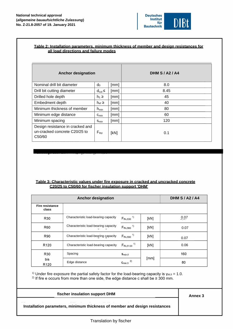
Anchor designation
DHM S / A2 / A4
Nominal drill bit diameter d0 [mm] 8.0
Drill bit cutting diameter dcut ≤ [mm] 8.45
Drilled hole depth h1 ≥ [mm] 45
Embedment depth hef ≥ [mm] 40
Minimum thickness of member hmin [mm] 80
Minimum edge distance cmin [mm] 60
Minimum spacing smin [mm] 120
Design resistance in cracked and
un-cracked concrete C20/25 to
C50/60
FRd
[kN]
0.1
Permissible load perm. F = FRd / γF where γF = 1.35
Anchor designation DHM S / A2 / A4
0.07
Characteristic load-bearing capacity
0.06
Table 2: Installation parameters, minimum thickness of member and design resistances for
all load directions and failure modes
Characteristic load-bearing capacity
0.07
Characteristic load-bearing capacity
Table 3: Characteristic values under fire exposure in cracked and uncracked concrete
C20/25 to C50/60 for fischer insulation support 'DHM'
Fire resistance class
Characteristic load-bearing capacity 0.07
Spacing
Edge distance
1) Under fire exposure the partial safety factor for the load-bearing capacity is γM,fi = 1.0. 2) If fire e occurs from more than one side, the edge distance c shall be ≥ 300 mm.
fischer insulation support DHM Annex 3
Installation parameters, minimum thickness of member and design resistances