transient modelling and catalyst deactivation in reaction...
TRANSCRIPT
1
Transient modelling and catalyst deactivation in reaction engineering
Tapio Salmi, Dmitry Murzin, Johan Wärnå, Esa Toukoniitty, Fredrik Sandelin
Åbo Akademi
Outline
Modelling of transient experimentsWhy transient experimentTransient techniquesModelling of transient experimentsResults (examples)
Catalyst deactivationAbout catalyst deactivationModelling of catalyst deactivationCase studies
2
Why transient experiments
Obtain more information on mechanism
Multiple reactions (sequence of steps, forward and backward rates, etc)Adsorption, reaction, desorption
Information on dynamic behavior (essential if reactor works in transient regime)Information on start-up and shut down behavior
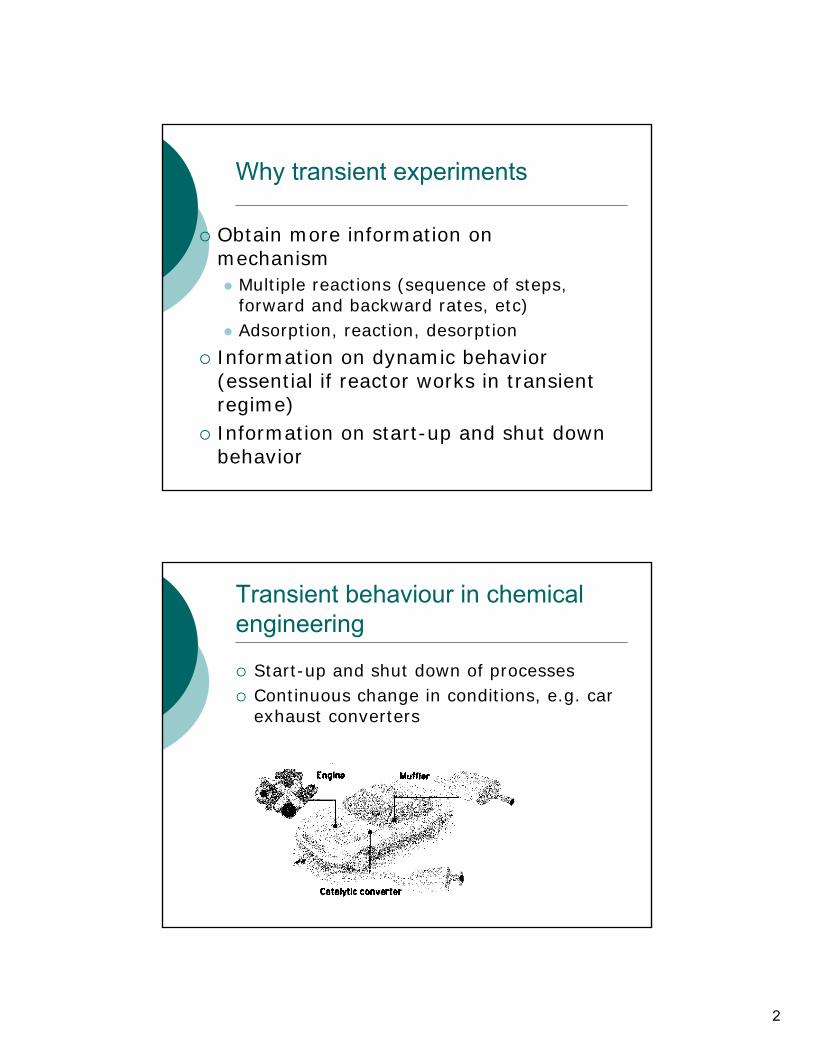
Transient behaviour in chemical engineering
Start-up and shut down of processesContinuous change in conditions, e.g. car exhaust converters
3
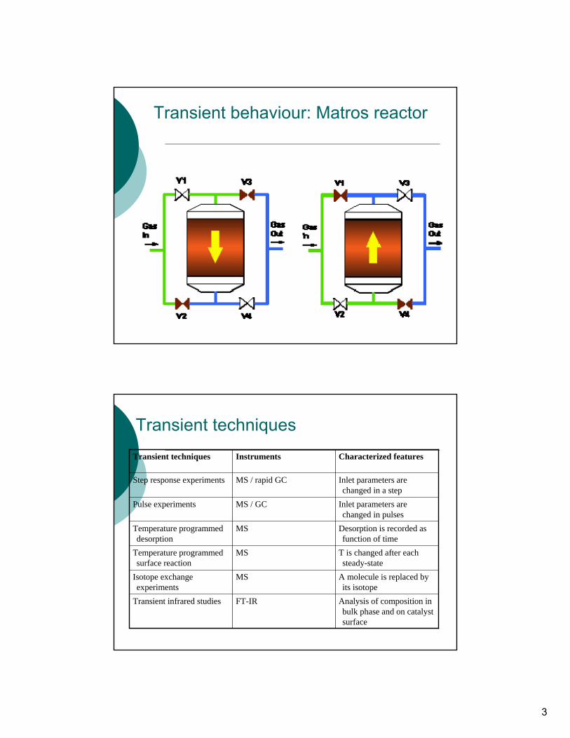
Transient behaviour: Matros reactor
Transient techniques
Analysis of composition in bulk phase and on catalyst surface
FT-IRTransient infrared studies
A molecule is replaced by its isotope
MSIsotope exchange experiments
T is changed after each steady-state
MSTemperature programmed surface reaction
Desorption is recorded as function of time
MSTemperature programmed desorption
Inlet parameters are changed in pulses
MS / GCPulse experiments
Inlet parameters are changed in a step
MS / rapid GCStep response experiments
Characterized featuresInstrumentsTransient techniques
4
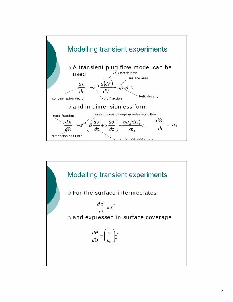
Modelling transient experiments
A transient plug flow model can be used
and in dimensionless form
( ) rdV
Vcddtcd
B11 −− +−= εσρε
&
jj r
dtd
α=Θ
rpRT
dzdx
dzxd
dxd B
0
01
ετσρδδε +⎟
⎠⎞
⎜⎝⎛ +−=
Θ−
void fraction
surface area
bulk density
volumetric flow
concentration vector
mole fraction
dimentionless time
dimentionless change in volumetric flow
dimentionless coordinate
Modelling transient experiments
For the surface intermediates
and expressed in surface coverage
**
rdtcd
=
*
0
rcd
d⎟⎟⎠
⎞⎜⎜⎝
⎛=
Θτθ
5
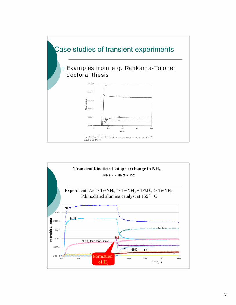
Case studies of transient experiments
Examples from e.g. Rahkama-Tolonendoctoral thesis
Transient kinetics: Isotope exchange in NH3
NH3 -> NH3 + D2
0.00E+00
5.00E-12
1.00E-11
1.50E-11
2.00E-11
2.50E-11
1400 1600 1800 2000 2200 2400 2600 2800
time, s
Inte
nsiti
es, a
mu
NH3
NH2
ND3, fragmentation
NH2D
H
H2
NHD2 HD
Experiment: Ar -> 1%NH3 -> 1%NH3 + 1%D2 -> 1%NH3, Pd/modified alumina catalyst at 155 °C
Formation of H2
6
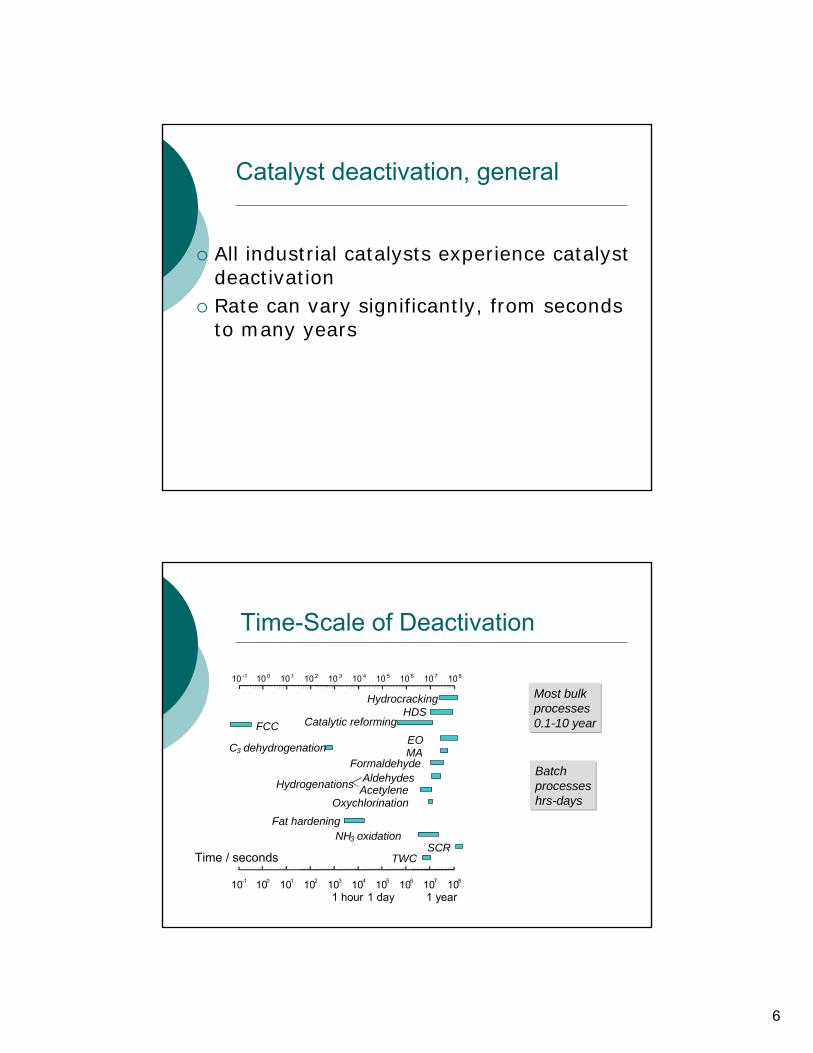
Catalyst deactivation, general
All industrial catalysts experience catalyst deactivationRate can vary significantly, from seconds to many years
Time-Scale of Deactivation
10 -1 10 0 10 1 10 2 10 3 10 4 10 5 10 6 10 7 108
HydrocrackingHDS
Catalytic reformingEO
Hydrogenations AldehydesAcetylene
Oxychlorination
MAFormaldehyde
NH3 oxidationSCR
Fat hardening
Time / seconds TWC
10-1 100 101 102 103 104 105 106 107 108
1 year1 day1 hour
C3 dehydrogenation
FCC
Most bulk processes0.1-10 year
Batch processeshrs-days
7
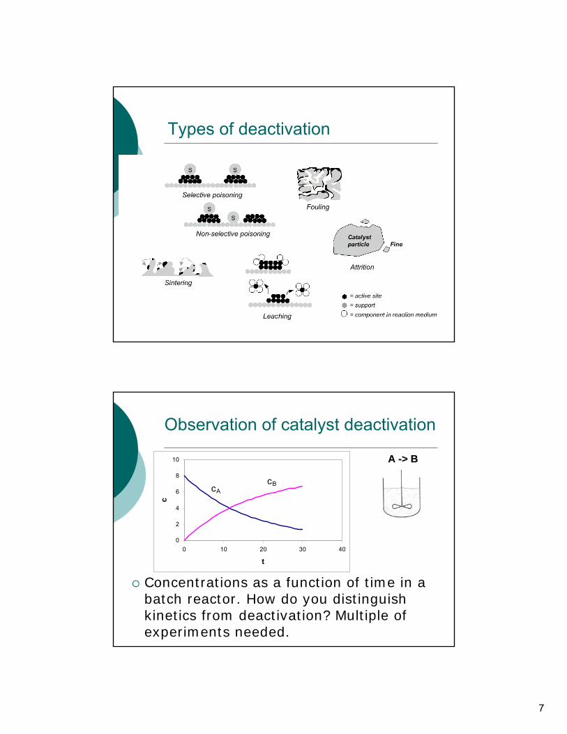
Types of deactivation
Observation of catalyst deactivation
0
2
4
6
8
10
0 10 20 30 40
t
c
cBcA
A A --> B > B
Concentrations as a function of time in a batch reactor. How do you distinguish kinetics from deactivation? Multiple of experiments needed.
8
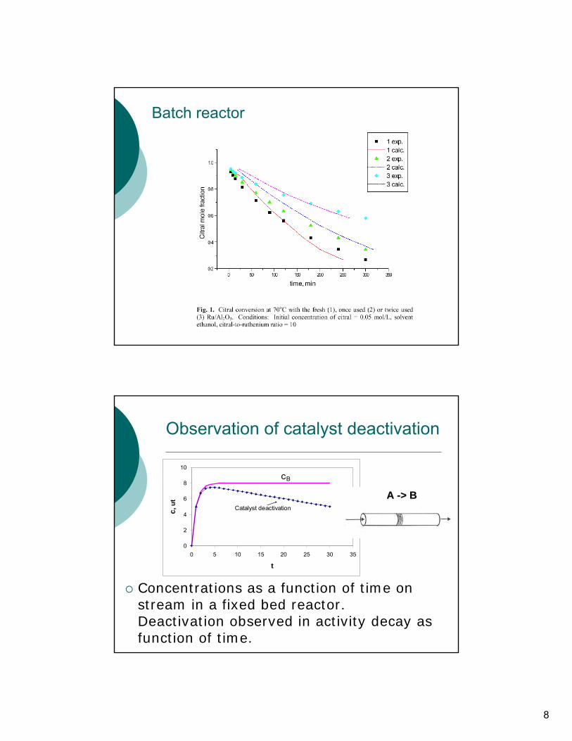
Batch reactor
Observation of catalyst deactivation
Concentrations as a function of time on stream in a fixed bed reactor. Deactivation observed in activity decay as function of time.
0
2
4
6
8
10
0 5 10 15 20 25 30 35
t
c, u
t
cB
Catalyst deactivation
A A --> B > B
9
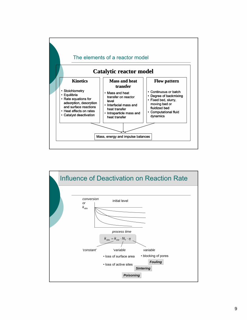
The elements of a reactor model
Catalytic reactor modelKinetics Mass and heat
transferFlow pattern
• Stoichiometry• Equilibria• Rate equations for
adsorption, desorption and surface reactions
• Heat effects on rates• Catalyst deactivation
• Mass and heat transfer on reactor level
• Interfacial mass and heat transfer
• Intraparticle mass and heat transfer
• Continuous or batch• Degree of backmixing• Fixed bed, slurry,
moving bed or fluidized bed
• Computational fluid dynamics
Mass, energy and impulse balances
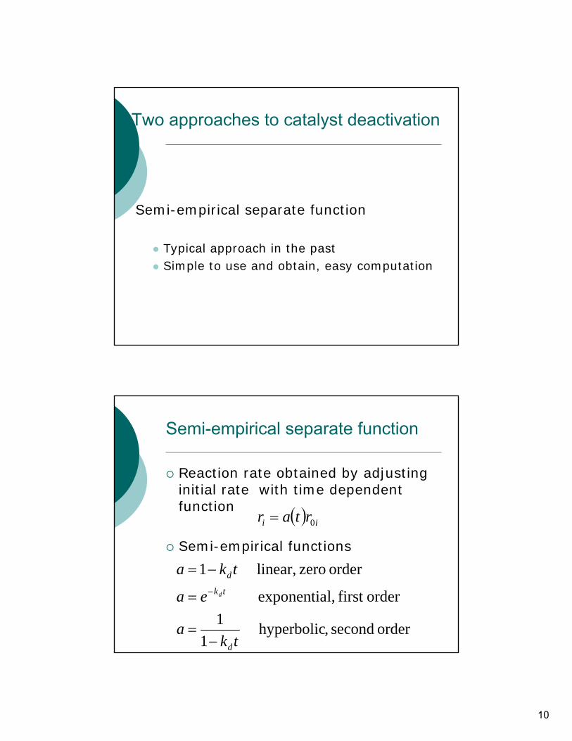
Influence of Deactivation on Reaction Rate
conversionorkobs
process time
η⋅⋅= Tintrobs Nkk
‘constant’ ‘variable variable
• blocking of pores• loss of surface area
• loss of active sitesFouling
Sintering
Poisoning
initial level
10
Two approaches to catalyst deactivation
Semi-empirical separate function
Typical approach in the pastSimple to use and obtain, easy computation
Semi-empirical separate function
Reaction rate obtained by adjusting initial rate with time dependent function
Semi-empirical functions
orderfirst l,exponentia tkdea −=
order second ,hyperbolic 1
1tk
ad−
=
( ) ii rtar 0=
order zero linear, 1 tka d−=
11
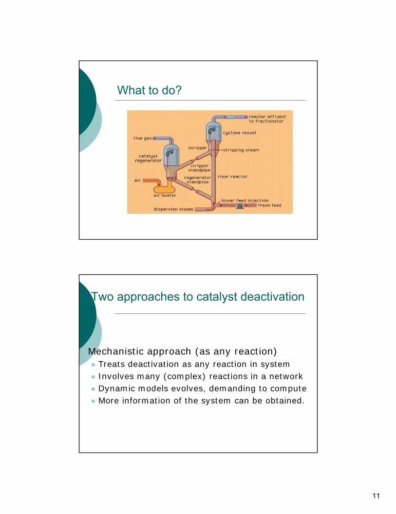
What to do?
Two approaches to catalyst deactivation
Mechanistic approach (as any reaction)Treats deactivation as any reaction in systemInvolves many (complex) reactions in a networkDynamic models evolves, demanding to computeMore information of the system can be obtained.
12
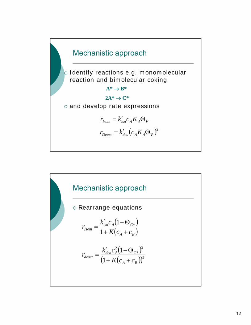
Mechanistic approach
Identify reactions e.g. monomolecular reaction and bimolecular coking
and develop rate expressions
A* → B*
2A* → C*
VAAisoIsom Kckr Θ′=
( )2VAAdeaDeact Kckr Θ′=
Mechanistic approach
Rearrange equations
( )( )BA
CAisoIsom ccK
ckr++Θ−′
=1
1 *
( )( )( )2
2*
2
11
BA
CAdeadeact ccK
ckr++Θ−′
=
13
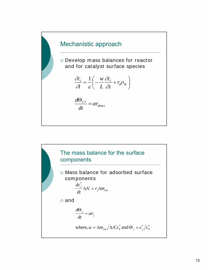
Mechanistic approach
Develop mass balances for reactor and for catalyst surface species
⎟⎠⎞
⎜⎝⎛ +−= Bi
ii rzc
Lw
tc ρ
∂∂
ε∂∂ 1
deactC r
dtd α=Θ *
The mass balance for the surfacecomponents
Mass balance for adsorbed surface components
and
catjj mr
dtdc
Δ=Α′Δ*
jj r
dtd
α=Θ
*0
**0 and where, cccm jjcat =ΘΑ′ΔΔ=α
14
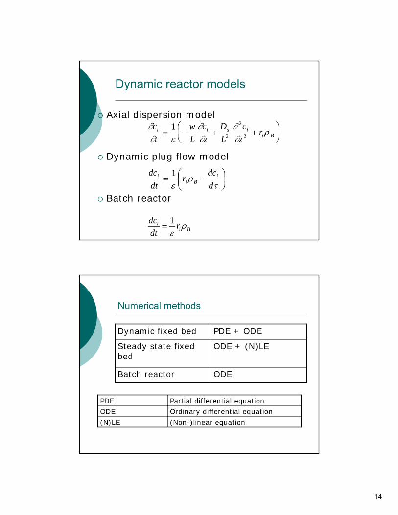
Dynamic reactor models
Axial dispersion model
Dynamic plug flow model
Batch reactor
Bii r
dtdc ρ
ε1
=
∂∂ ε
∂∂
∂∂
ρct
wL
cz
DL
cz
ri i a ii B= − + +
⎛⎝⎜
⎞⎠⎟
12
2
2
⎟⎠⎞
⎜⎝⎛ −=
τρ
ε ddc
rdtdc i
Bii 1
Numerical methods
ODEBatch reactor
ODE + (N)LESteady state fixedbed
PDE + ODEDynamic fixed bed
(Non-)linear equation(N)LE
Ordinary differential equationODE
Partial differential equationPDE
15
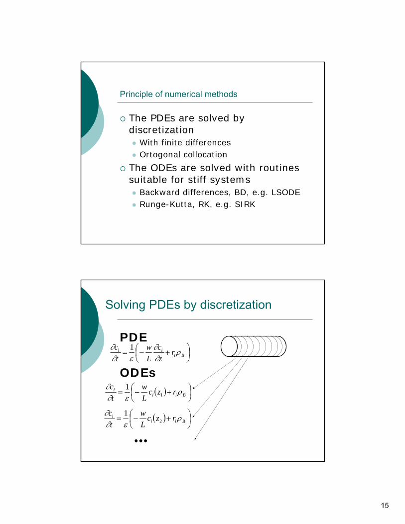
Principle of numerical methods
The PDEs are solved by discretization
With finite differencesOrtogonal collocation
The ODEs are solved with routinessuitable for stiff systems
Backward differences, BD, e.g. LSODERunge-Kutta, RK, e.g. SIRK
Solving PDEs by discretization
PDE
ODEs
⎟⎠⎞
⎜⎝⎛ +−= Bi
ii rzc
Lw
tc ρ
∂∂
ε∂∂ 1
( ) ⎟⎠⎞
⎜⎝⎛ +−= Bii
i rzcLw
tc ρ
ε∂∂
11
•••
( ) ⎟⎠⎞
⎜⎝⎛ +−= Bii
i rzcLw
tc ρ
ε∂∂
21
16
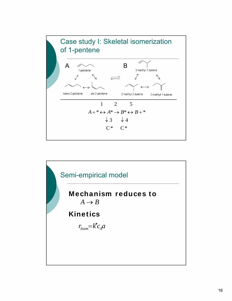
Case study I: Skeletal isomerizationof 1-pentene
A B
*C *C4 3
****5 2 1
↓↓+↔→↔+ BBAA
Semi-empirical model
Mechanism reduces to
Kinetics
ackr AIsom ′′=
BA→
17
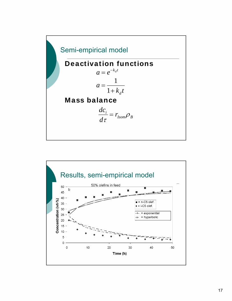
Semi-empirical model
Deactivation functions
Mass balance
tkdea −=
tka
d+=
11
BIsomi r
ddc ρτ=
Results, semi-empirical model
18
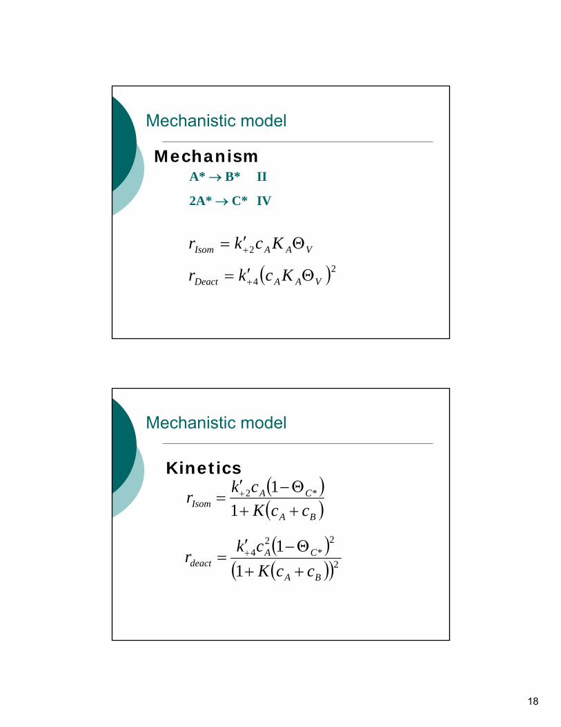
Mechanistic model
MechanismA* → B* II
2A* → C* IV
VAAIsom Kckr Θ′= +2
( )24 VAADeact Kckr Θ′= +
Mechanistic model
Kinetics( )( )BA
CAIsom ccK
ckr++Θ−′
= +
11 *2
( )( )( )2
2*
24
11
BA
CAdeact ccK
ckr++Θ−′
= +
19
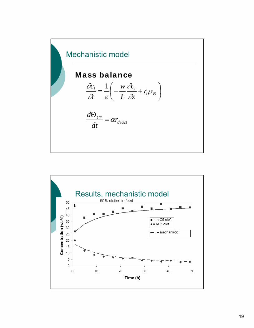
Mechanistic model
Mass balance
⎟⎠⎞
⎜⎝⎛ +−= Bi
ii rzc
Lw
tc ρ
∂∂
ε∂∂ 1
deactC r
dtd α=Θ *
Results, mechanistic model

20
Results, mechanistic model
Investigate deactivation mechanisms
Isomerization
Deactivation mechanisms
A* →B* II
2A* → C* IVa
A* → C* IVb
B* → C* IVc
A* ↔ C* IVd
21
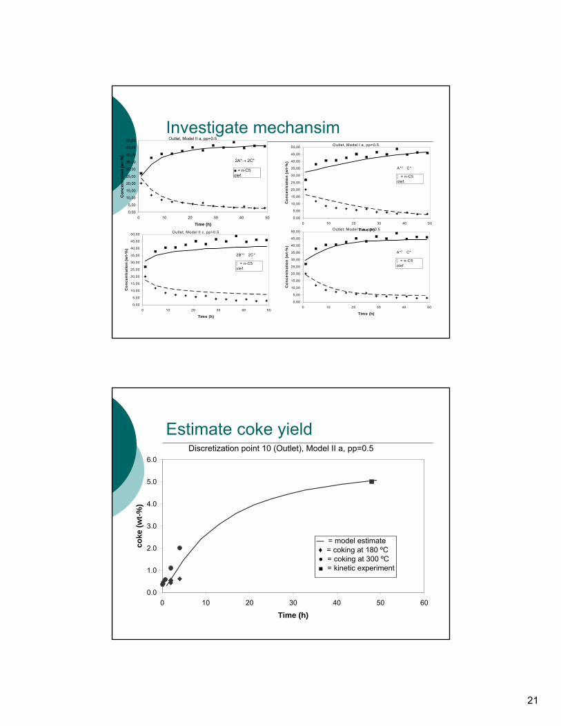
Investigate mechansim
0,00
5,00
10,00
15,00
20,00
25,00
30,00
35,00
40,00
45,00
50,00
0 10 20 30 40 50
Time (h)
Co
ncen
trat
ion
(wt-
%)
¦ = n-C5 olef.
Outlet, Model I a, pp=0.5
A*? C*
0,00
5,00
10,00
15,00
20,00
25,00
30,00
35,00
40,00
45,00
50,00
0 10 20 30 40 50
Time (h)
Co
ncen
trat
ion
(wt-
%)
¦ = n-C5 olef.
Outlet, Model II c, pp=0.5
2B*? 2C*
0,00
5,00
10,00
15,00
20,00
25,00
30,00
35,00
40,00
45,00
50,00
0 10 20 30 40 50
Time (h)
Co
ncen
trat
ion
(wt-
%)
¦ = n-C5 olef.
Outlet, Model V a, pp=0.5
A*? C*
0,00
5,00
10,00
15,00
20,00
25,00
30,00
35,00
40,00
45,00
50,00
0 10 20 30 40 50
Time (h)
Con
cent
ratio
n (w
t-%)
■ = n-C5 olef.
Outlet, Model II a, pp=0.5
2A*→ 2C*
Estimate coke yield
0.0
1.0
2.0
3.0
4.0
5.0
6.0
0 10 20 30 40 50 60
Time (h)
coke
(wt-%
)
Discretization point 10 (Outlet), Model II a, pp=0.5
— = model estimate ♦ = coking at 180 ºC ● = coking at 300 ºC ■ = kinetic experiment
22
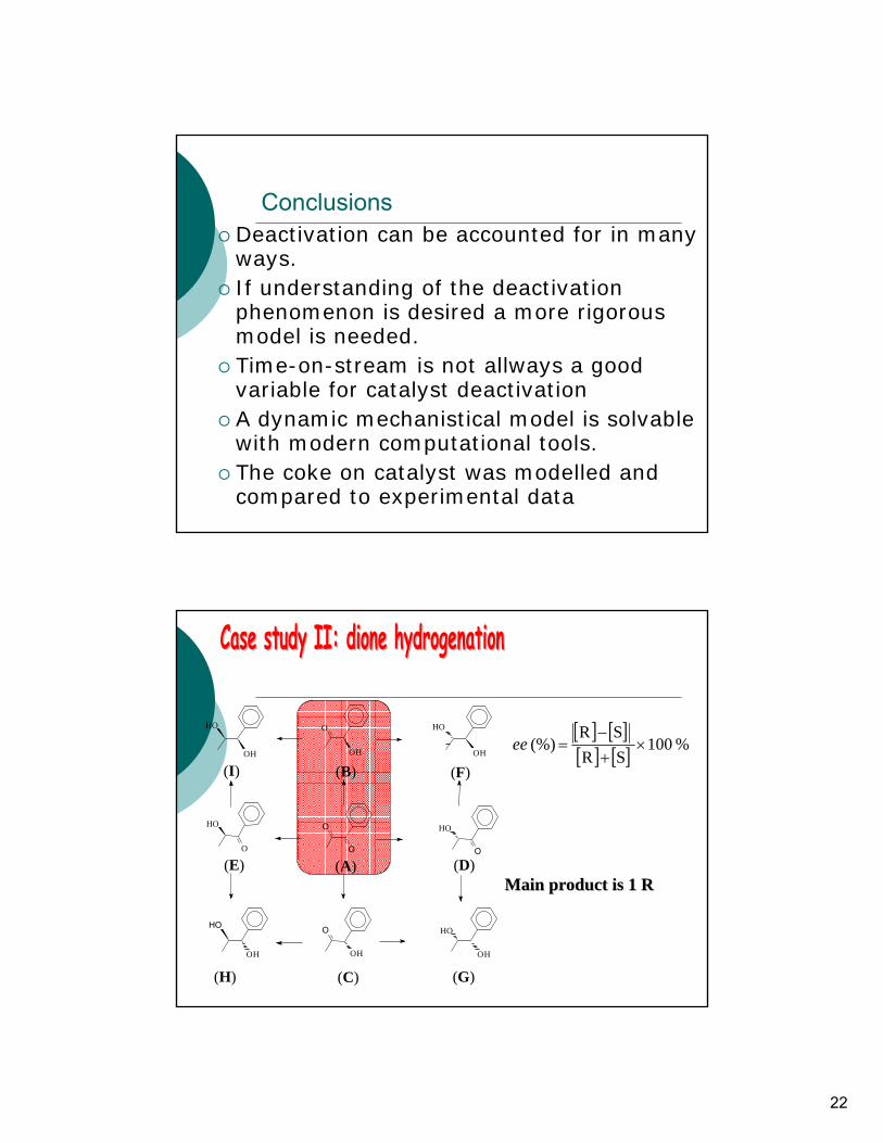
ConclusionsDeactivation can be accounted for in manyways.If understanding of the deactivationphenomenon is desired a more rigorousmodel is needed.Time-on-stream is not allways a goodvariable for catalyst deactivationA dynamic mechanistical model is solvablewith modern computational tools.The coke on catalyst was modelled and compared to experimental data
O
O
O
OH
O
OH
O
HO
O
HO
OH
HO
(B)
(C)
(D)(E)
OH
HO
HO
OH
(I) (F)
(G)(H)
(A)
OH
HO
Main product is Main product is 1 R1 R
[ ] [ ][ ] [ ] % 100
SRSR
(%) ×+−
=ee
23
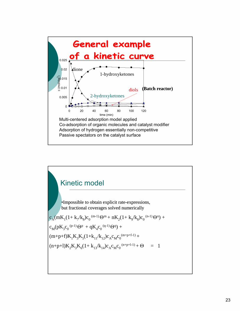
0
0.005
0.01
0.015
0.02
0.025
0 20 40 60 80 100 120time (min)
c (m
ol/d
m3 )
(Batch reactor)(Batch reactor)
dione1-hydroxyketones
2-hydroxyketonesdiols
Multi-centered adsorption model appliedCo-adsorption of organic molecules and catalyst modifierAdsorption of hydrogen essentially non-competitivePassive spectators on the catalyst surface
Kinetic model
cA(mK1(1+ k7/k8)c0 (m-1)Θm + nK2(1+ k9/k8)c0
(n-1)Θn) +
cM(pK3c0 (p-1)Θp + qK4c0
(q-1)Θq) +
(m+p+f)K1K3K5(1+k11/k12)cAcMc0(m+p+f-1) +
(n+p+l)K2K3K6(1+ k13/k14)cAcMc0 (n+p+l-1) + Θ = 1
••Impossible to obtain explicit rateImpossible to obtain explicit rate--expressions, expressions, but fractional but fractional coveragescoverages solved numericallysolved numerically
24
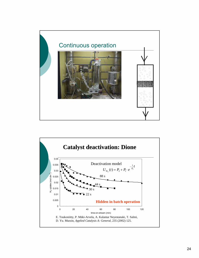
Continuous operation
0
0.005
0.01
0.015
0.02
0.025
0.03
0.035
0.04
0 20 40 60 80 100 120time-on-stream (min)
H2 u
ptak
e (m
ol d
m-3
)
Catalyst deactivationCatalyst deactivation: : DioneDione
22 s30 s
44 s
88 s
tePPtU P2
2
1
13H )(−
⋅+=
Deactivation model
E. Toukoniitty, P. Mäki-Arvela, A. Kalantar Neyestanaki, T. Salmi, D. Yu. Murzin, Applied Catalysis A: General, 235 (2002) 125.
Hidden in batch operation
25
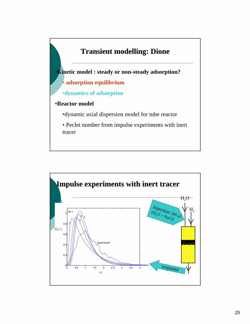
Transient modellingTransient modelling: : DioneDione
•Kinetic model : steady or non-steady adsorption?
• adsorption equilibrium
•dynamics of adsorption
•Reactor model
•dynamic axial dispersion model for tube reactor
• Peclet number from impulse experiments with inert tracer
Impulse experiments with inert tracerImpulse experiments with inert tracer
0 0.5 1 1.5 2 2.5 3 3.5 40
0.2
0.4
0.6
0.8
1 Pe =
1 3 5 7
Experiment
t/τ
E(t ) τ
H2
H2O
response
Injection 200 μl (H
2O + NaCl)
26
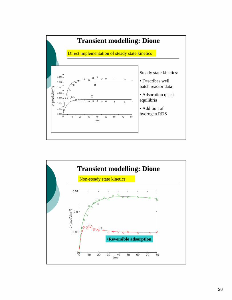
Transient modellingTransient modelling: : DioneDione
0.000
0.002
0.004
0.006
0.008
0.010
0.012
0.014
0 10 20 30 40 50 60 70 80
time
B
C
Direct implementation of steady state kineticsc
(mol
/ dm
-3)
Steady state kinetics:
• Describes well batch reactor data
• Adsorption quasi-equilibria
• Addition of hydrogen RDS
Transient modellingTransient modelling: : DioneDione
5 μm
0 10 20 30 40 50 60 70 800
0.00
0.0
0.01
time
B
C
Non-steady state kinetics
c (m
ol/ d
m-3
)
•Reversible adsorption
27
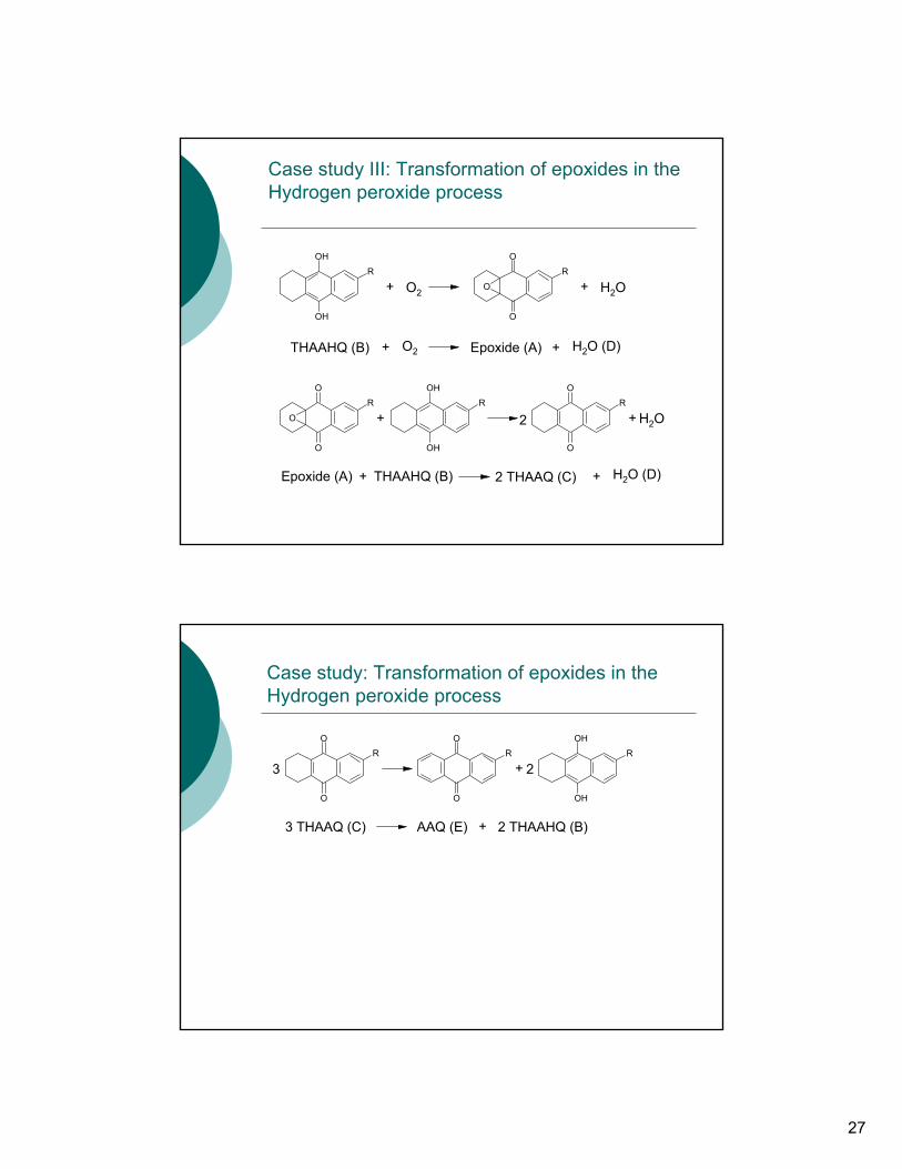
Case study III: Transformation of epoxides in the Hydrogen peroxide process
O
OR
O
OH
OHR
+
+ O2
O2
THAAHQ (B) Epoxide (A) + H2O (D)
+ H2O
O
OR
O
OH
OHR
O
OR
+
+ THAAHQ (B)Epoxide (A) + H2O (D)
+ H2O
2 THAAQ (C)
2
Case study: Transformation of epoxides in the Hydrogen peroxide process
O
OR
OH
OHR
O
OR
+
+AAQ (E)3 THAAQ (C) 2 THAAHQ (B)
23
28
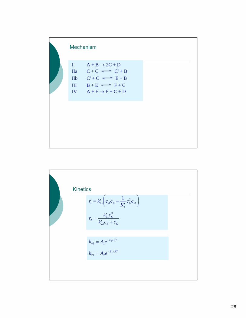
Mechanism
I A + B → 2C + D IIa C + C C' + B IIb C' + C E + B III B + E F + C IV A + F → E + C + D
Kinetics
r k c cK
c cA B C D1 11
21= ′ −
′⎛⎝⎜
⎞⎠⎟+
rk c
k c cC
B C2
213
22
=′
′ +
′ =+−k A e E RT
1 11 /
′ = −k A e E RT21 2
2 /
29
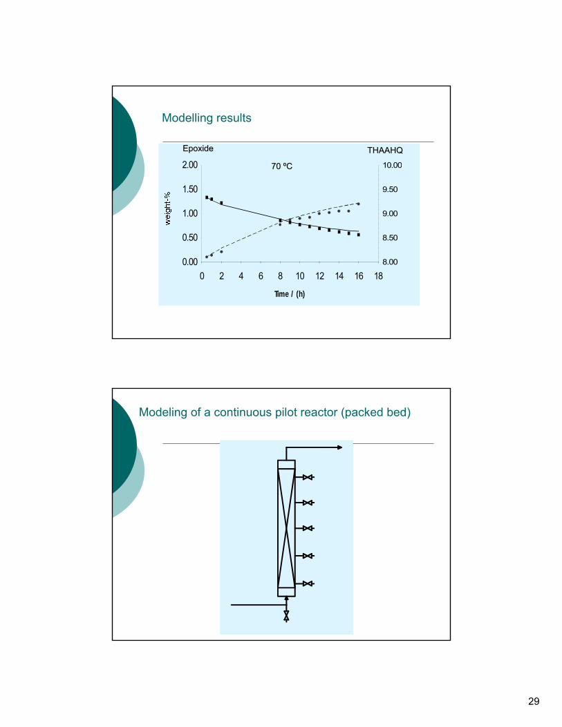
Modelling results
Time / (h)
0.00
0.50
1.00
1.50
2.00
0 2 4 6 8 10 12 14 16 188.00
8.50
9.00
9.50
10.00
EpoxideEpoxide THAAHQTHAAHQ
70 70 ººCC
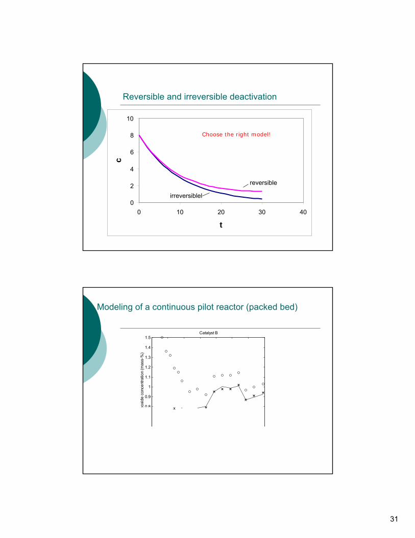
Modeling of a continuous pilot reactor (packed bed)
30
Dispersion model
Reaction kinetics and deactivation function
Stoichiometry
Modeling of a continuous pilot reactor (packed bed)
∂∂ ε
∂∂
∂∂
ρct
wL
cz
DL
cz
ri i a ii B= − + +
⎛⎝⎜
⎞⎠⎟
12
2
2
( ) jj rtar 0=
jiji rr 0∑= ν
Semi-empirical description of catalyst deactivation
P + * P*
( )dadt
k a a n= − ′ − ∗
( ) 1, )( 0 =∗−+∗= ′− neaaata tk
( ) ( )[ ]a t a a a k n t nn n( ) ,= ∗ + − ∗ + ′ − ≠− − 01
111 1
r k c c k cP P v P= −+ − ∗
31
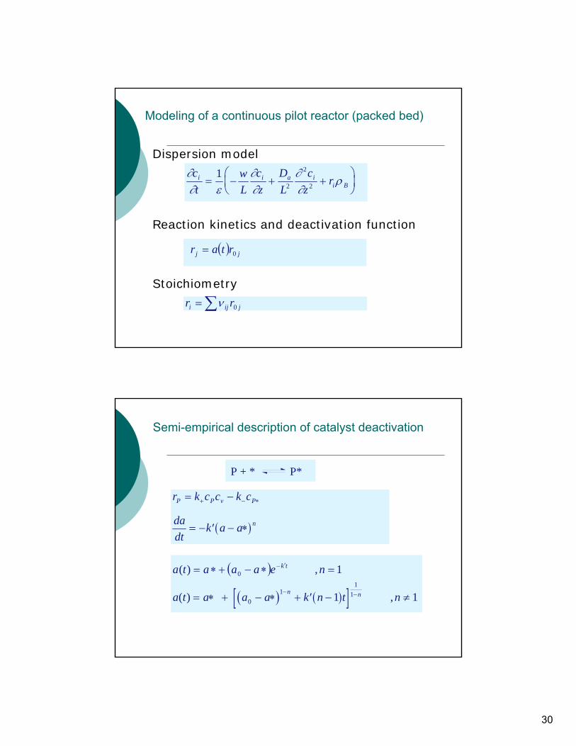
Reversible and irreversible deactivation
ChooseChoose the the rightright modelmodelfor for deactivationdeactivation !!
0
2
4
6
8
10
0 10 20 30 40
t
c
reversible
irreversiblel
Choose the right model!
Modeling of a continuous pilot reactor (packed bed)
0 8
0.9
1
1.1
1.2
1.3
1.4
1.5 Catalyst B
poxi
de c
once
ntra
tion
(mas
s-%
)