transformers - wbuthelp.com · number of turns in wire coil ... minimized if it is designed for and...
TRANSCRIPT

TRANSFORMERS
mywbut.com
1

9.1 Mutual inductance and basic operation
Suppose we were to wrap a coil of insulated wire around a loop of ferromagnetic material andenergize this coil with an AC voltage source: (Figure 9.1 (a))
wirecoil
iron core
resistor
(a) (b)
Figure 9.1: Insulated winding on ferromagnetic loop has inductive reactance, limiting AC cur-rent.
As an inductor, we would expect this iron-core coil to oppose the applied voltage with itsinductive reactance, limiting current through the coil as predicted by the equations XL = 2πfLand I=E/X (or I=E/Z). For the purposes of this example, though, we need to take a more detailedlook at the interactions of voltage, current, and magnetic flux in the device.Kirchhoff ’s voltage law describes how the algebraic sum of all voltages in a loop must equal
zero. In this example, we could apply this fundamental law of electricity to describe the respec-tive voltages of the source and of the inductor coil. Here, as in any one-source, one-load circuit,the voltage dropped across the load must equal the voltage supplied by the source, assumingzero voltage dropped along the resistance of any connecting wires. In other words, the load(inductor coil) must produce an opposing voltage equal in magnitude to the source, in orderthat it may balance against the source voltage and produce an algebraic loop voltage sum ofzero. From where does this opposing voltage arise? If the load were a resistor (Figure 9.1(b)), the voltage drop originates from electrical energy loss, the “friction” of electrons flowingthrough the resistance. With a perfect inductor (no resistance in the coil wire), the opposingvoltage comes from another mechanism: the reaction to a changing magnetic flux in the ironcore. When AC current changes, flux Φ changes. Changing flux induces a counter EMF.Michael Faraday discovered the mathematical relationship between magnetic flux (Φ) and
induced voltage with this equation:
dΦdt
Where,
N
N =
Φ =t =
Number of turns in wire coil (straight wire = 1)Magnetic flux in WebersTime in seconds
e =
e = (Instantaneous) induced voltage in volts
mywbut.com
2

The instantaneous voltage (voltage dropped at any instant in time) across a wire coil isequal to the number of turns of that coil around the core (N) multiplied by the instantaneousrate-of-change in magnetic flux (dΦ/dt) linking with the coil. Graphed, (Figure 9.2) this showsitself as a set of sine waves (assuming a sinusoidal voltage source), the flux wave 90o laggingbehind the voltage wave:
e = voltage Φ = magnetic flux
e Φ
Figure 9.2: Magnetic flux lags applied voltage by 90o because flux is proportional to a rate ofchange, dΦ/dt.
Magnetic flux through a ferromagnetic material is analogous to current through a conduc-tor: it must be motivated by some force in order to occur. In electric circuits, this motivatingforce is voltage (a.k.a. electromotive force, or EMF). In magnetic “circuits,” this motivatingforce is magnetomotive force, or mmf. Magnetomotive force (mmf) and magnetic flux (Φ) arerelated to each other by a property of magnetic materials known as reluctance (the latter quan-tity symbolized by a strange-looking letter “R”):
Electrical Magnetic
E = IR mmf = Φℜ
A comparison of "Ohm’s Law" forelectric and magnetic circuits:
In our example, the mmf required to produce this changing magnetic flux (Φ) must be sup-plied by a changing current through the coil. Magnetomotive force generated by an electro-magnet coil is equal to the amount of current through that coil (in amps) multiplied by thenumber of turns of that coil around the core (the SI unit for mmf is the amp-turn). Becausethe mathematical relationship between magnetic flux and mmf is directly proportional, andbecause the mathematical relationship between mmf and current is also directly proportional(no rates-of-change present in either equation), the current through the coil will be in-phasewith the flux wave as in (Figure 9.3)This is why alternating current through an inductor lags the applied voltage waveform
by 90o: because that is what is required to produce a changing magnetic flux whose rate-of-change produces an opposing voltage in-phase with the applied voltage. Due to its function inproviding magnetizing force (mmf) for the core, this current is sometimes referred to as themagnetizing current.It should be mentioned that the current through an iron-core inductor is not perfectly sinu-
soidal (sine-wave shaped), due to the nonlinear B/H magnetization curve of iron. In fact, if the
mywbut.com
3

e = voltage Φ = magnetic flux i = coil current
e Φi
Figure 9.3: Magnetic flux, like current, lags applied voltage by 90o.
inductor is cheaply built, using as little iron as possible, the magnetic flux density might reachhigh levels (approaching saturation), resulting in a magnetizing current waveform that lookssomething like Figure 9.4
e = voltageΦ = magnetic flux
i = coil current
e Φi
Figure 9.4: As flux density approaches saturation, the magnetizing current waveform becomesdistorted.
When a ferromagnetic material approaches magnetic flux saturation, disproportionatelygreater levels of magnetic field force (mmf) are required to deliver equal increases in magneticfield flux (Φ). Because mmf is proportional to current through the magnetizing coil (mmf = NI,where “N” is the number of turns of wire in the coil and “I” is the current through it), the largeincreases of mmf required to supply the needed increases in flux results in large increasesin coil current. Thus, coil current increases dramatically at the peaks in order to maintaina flux waveform that isn’t distorted, accounting for the bell-shaped half-cycles of the currentwaveform in the above plot.The situation is further complicated by energy losses within the iron core. The effects of
hysteresis and eddy currents conspire to further distort and complicate the current waveform,making it even less sinusoidal and altering its phase to be lagging slightly less than 90o behindthe applied voltage waveform. This coil current resulting from the sum total of all magneticeffects in the core (dΦ/dt magnetization plus hysteresis losses, eddy current losses, etc.) iscalled the exciting current. The distortion of an iron-core inductor’s exciting current may beminimized if it is designed for and operated at very low flux densities. Generally speaking, this
mywbut.com
4

requires a core with large cross-sectional area, which tends to make the inductor bulky andexpensive. For the sake of simplicity, though, we’ll assume that our example core is far fromsaturation and free from all losses, resulting in a perfectly sinusoidal exciting current.
As we’ve seen already in the inductors chapter, having a current waveform 90o out of phasewith the voltage waveform creates a condition where power is alternately absorbed and re-turned to the circuit by the inductor. If the inductor is perfect (no wire resistance, no magneticcore losses, etc.), it will dissipate zero power.
Let us now consider the same inductor device, except this time with a second coil (Fig-ure 9.5) wrapped around the same iron core. The first coil will be labeled the primary coil,while the second will be labeled the secondary:
wirecoil
iron core
wirecoil
Figure 9.5: Ferromagnetic core with primary coil (AC driven) and secondary coil.
If this secondary coil experiences the same magnetic flux change as the primary (whichit should, assuming perfect containment of the magnetic flux through the common core), andhas the same number of turns around the core, a voltage of equal magnitude and phase tothe applied voltage will be induced along its length. In the following graph, (Figure 9.6) theinduced voltage waveform is drawn slightly smaller than the source voltage waveform simplyto distinguish one from the other:
This effect is called mutual inductance: the induction of a voltage in one coil in response toa change in current in the other coil. Like normal (self-) inductance, it is measured in the unitof Henrys, but unlike normal inductance it is symbolized by the capital letter “M” rather thanthe letter “L”:
mywbut.com
5

Φ = magnetic flux
Φ
ep = primary coil voltagees = secondary coil voltage
ep
es
ip = primary coil current
ip
Figure 9.6: Open circuited secondary sees the same flux Φ as the primary. Therefore inducedsecondary voltage es is the same magnitude and phase as the primary voltage ep.
e = Ldi
dt
Inductance Mutual inductance
e2 = Mdi1
dt
Where,
e2 = voltage induced insecondary coil
i1 = current in primarycoil
No current will exist in the secondary coil, since it is open-circuited. However, if we connecta load resistor to it, an alternating current will go through the coil, in-phase with the inducedvoltage (because the voltage across a resistor and the current through it are always in-phasewith each other). (Figure 9.7)
At first, one might expect this secondary coil current to cause additional magnetic flux in thecore. In fact, it does not. If more flux were induced in the core, it would cause more voltage tobe induced voltage in the primary coil (remember that e = dΦ/dt). This cannot happen, becausethe primary coil’s induced voltage must remain at the same magnitude and phase in order tobalance with the applied voltage, in accordance with Kirchhoff ’s voltage law. Consequently,the magnetic flux in the core cannot be affected by secondary coil current. However, what doeschange is the amount of mmf in the magnetic circuit.
Magnetomotive force is produced any time electrons move through a wire. Usually, thismmf is accompanied by magnetic flux, in accordance with the mmf=ΦR “magnetic Ohm’s Law”equation. In this case, though, additional flux is not permitted, so the only way the secondarycoil’s mmf may exist is if a counteracting mmf is generated by the primary coil, of equal mag-nitude and opposite phase. Indeed, this is what happens, an alternating current forming inthe primary coil – 180o out of phase with the secondary coil’s current – to generate this coun-teracting mmf and prevent additional core flux. Polarity marks and current direction arrowshave been added to the illustration to clarify phase relations: (Figure 9.8)
If you find this process a bit confusing, do not worry. Transformer dynamics is a complex
mywbut.com
6

wirecoil
iron core
wirecoil
Figure 9.7: Resistive load on secondary has voltage and current in-phase.
wirecoil
iron core
wirecoil
+
-
+
-
+
-
+
-
mmfprimary
mmfsecondary
Figure 9.8: Flux remains constant with application of a load. However, a counteracting mmf isproduced by the loaded secondary.
mywbut.com
7

subject. What is important to understand is this: when an AC voltage is applied to the primarycoil, it creates a magnetic flux in the core, which induces AC voltage in the secondary coil in-phase with the source voltage. Any current drawn through the secondary coil to power a loadinduces a corresponding current in the primary coil, drawing current from the source.Notice how the primary coil is behaving as a load with respect to the AC voltage source,
and how the secondary coil is behaving as a source with respect to the resistor. Rather thanenergy merely being alternately absorbed and returned the primary coil circuit, energy is nowbeing coupled to the secondary coil where it is delivered to a dissipative (energy-consuming)load. As far as the source “knows,” its directly powering the resistor. Of course, there is also anadditional primary coil current lagging the applied voltage by 90o, just enough to magnetizethe core to create the necessary voltage for balancing against the source (the exciting current).We call this type of device a transformer, because it transforms electrical energy into mag-
netic energy, then back into electrical energy again. Because its operation depends on electro-magnetic induction between two stationary coils and a magnetic flux of changing magnitudeand “polarity,” transformers are necessarily AC devices. Its schematic symbol looks like twoinductors (coils) sharing the same magnetic core: (Figure 9.9)
Transformer
Figure 9.9: Schematic symbol for transformer consists of two inductor symbols, separated bylines indicating a ferromagnetic core.
The two inductor coils are easily distinguished in the above symbol. The pair of verti-cal lines represent an iron core common to both inductors. While many transformers haveferromagnetic core materials, there are some that do not, their constituent inductors beingmagnetically linked together through the air.The following photograph shows a power transformer of the type used in gas-discharge
lighting. Here, the two inductor coils can be clearly seen, wound around an iron core. Whilemost transformer designs enclose the coils and core in a metal frame for protection, this partic-ular transformer is open for viewing and so serves its illustrative purpose well: (Figure 9.10)Both coils of wire can be seen here with copper-colored varnish insulation. The top coil is
larger than the bottom coil, having a greater number of “turns” around the core. In trans-formers, the inductor coils are often referred to as windings, in reference to the manufacturingprocess where wire is wound around the core material. As modeled in our initial example, thepowered inductor of a transformer is called the primary winding, while the unpowered coil iscalled the secondary winding.In the next photograph, Figure 9.11, a transformer is shown cut in half, exposing the cross-
section of the iron core as well as both windings. Like the transformer shown previously, thisunit also utilizes primary and secondary windings of differing turn counts. The wire gauge canalso be seen to differ between primary and secondary windings. The reason for this disparityin wire gauge will be made clear in the next section of this chapter. Additionally, the iron corecan be seen in this photograph to be made of many thin sheets (laminations) rather than a
mywbut.com
8

Figure 9.10: Example of a gas-discharge lighting transformer.
solid piece. The reason for this will also be explained in a later section of this chapter.
Figure 9.11: Transformer cross-section cut shows core and windings.
It is easy to demonstrate simple transformer action using SPICE, setting up the primaryand secondary windings of the simulated transformer as a pair of “mutual” inductors. (Fig-
mywbut.com
9

ure 9.12) The coefficient of magnetic field coupling is given at the end of the “k” line in theSPICE circuit description, this example being set very nearly at perfection (1.000). This co-efficient describes how closely “linked” the two inductors are, magnetically. The better thesetwo inductors are magnetically coupled, the more efficient the energy transfer between themshould be.
(for SPICE to measure current)
1
0
2
0
3 4
5 5
L1 L2
Vi1
0 V
Rload 1 kΩV1 10 V100 H 100 H
Rbogus1
Rbogus2
(very small)
(very large)
Figure 9.12: Spice circuit for coupled inductors.
transformerv1 1 0 ac 10 sinrbogus1 1 2 1e-12rbogus2 5 0 9e12l1 2 0 100l2 3 5 100
** This line tells SPICE that the two inductors
** l1 and l2 are magnetically ‘‘linked’’ togetherk l1 l2 0.999vi1 3 4 ac 0rload 4 5 1k.ac lin 1 60 60.print ac v(2,0) i(v1).print ac v(3,5) i(vi1).end
Note: the Rbogus resistors are required to satisfy certain quirks of SPICE. The first breaksthe otherwise continuous loop between the voltage source and L1 which would not be permittedby SPICE. The second provides a path to ground (node 0) from the secondary circuit, necessarybecause SPICE cannot function with any ungrounded circuits.Note that with equal inductances for both windings (100 Henrys each), the AC voltages and
currents are nearly equal for the two. The difference between primary and secondary currentsis the magnetizing current spoken of earlier: the 90o lagging current necessary to magnetizethe core. As is seen here, it is usually very small compared to primary current induced by theload, and so the primary and secondary currents are almost equal. What you are seeing here
mywbut.com
10

freq v(2) i(v1)6.000E+01 1.000E+01 9.975E-03 Primary winding
freq v(3,5) i(vi1)6.000E+01 9.962E+00 9.962E-03 Secondary winding
is quite typical of transformer efficiency. Anything less than 95% efficiency is considered poorfor modern power transformer designs, and this transfer of power occurs with no moving partsor other components subject to wear.If we decrease the load resistance so as to draw more current with the same amount of volt-
age, we see that the current through the primary winding increases in response. Even thoughthe AC power source is not directly connected to the load resistance (rather, it is electromag-netically “coupled”), the amount of current drawn from the source will be almost the same asthe amount of current that would be drawn if the load were directly connected to the source.Take a close look at the next two SPICE simulations, showing what happens with differentvalues of load resistors:
transformerv1 1 0 ac 10 sinrbogus1 1 2 1e-12rbogus2 5 0 9e12l1 2 0 100l2 3 5 100k l1 l2 0.999vi1 3 4 ac 0
** Note load resistance value of 200 ohmsrload 4 5 200.ac lin 1 60 60.print ac v(2,0) i(v1).print ac v(3,5) i(vi1).end
freq v(2) i(v1)6.000E+01 1.000E+01 4.679E-02
freq v(3,5) i(vi1)6.000E+01 9.348E+00 4.674E-02
Notice how the primary current closely follows the secondary current. In our first simula-tion, both currents were approximately 10 mA, but now they are both around 47 mA. In thissecond simulation, the two currents are closer to equality, because the magnetizing currentremains the same as before while the load current has increased. Note also how the secondaryvoltage has decreased some with the heavier (greater current) load. Let’s try another simula-tion with an even lower value of load resistance (15 Ω):Our load current is now 0.13 amps, or 130 mA, which is substantially higher than the
last time. The primary current is very close to being the same, but notice how the secondary
mywbut.com
11

transformerv1 1 0 ac 10 sinrbogus1 1 2 1e-12rbogus2 5 0 9e12l1 2 0 100l2 3 5 100k l1 l2 0.999vi1 3 4 ac 0rload 4 5 15.ac lin 1 60 60.print ac v(2,0) i(v1).print ac v(3,5) i(vi1).end
freq v(2) i(v1)6.000E+01 1.000E+01 1.301E-01
freq v(3,5) i(vi1)6.000E+01 1.950E+00 1.300E-01
voltage has fallen well below the primary voltage (1.95 volts versus 10 volts at the primary).The reason for this is an imperfection in our transformer design: because the primary andsecondary inductances aren’t perfectly linked (a k factor of 0.999 instead of 1.000) there is“stray” or “leakage” inductance. In other words, some of the magnetic field isn’t linking withthe secondary coil, and thus cannot couple energy to it: (Figure 9.13)
wirecoil
wirecoil
leakageflux
leakageflux
core flux
Figure 9.13: Leakage inductance is due to magnetic flux not cutting both windings.
Consequently, this “leakage” flux merely stores and returns energy to the source circuitvia self-inductance, effectively acting as a series impedance in both primary and secondarycircuits. Voltage gets dropped across this series impedance, resulting in a reduced load voltage:
mywbut.com
12

voltage across the load “sags” as load current increases. (Figure 9.14)
idealtransformer
leakageinductance
leakageinductance
Source Load
Figure 9.14: Equivalent circuit models leakage inductance as series inductors independent ofthe “ideal transformer”.
If we change the transformer design to have better magnetic coupling between the primaryand secondary coils, the figures for voltage between primary and secondary windings will bemuch closer to equality again:
transformerv1 1 0 ac 10 sinrbogus1 1 2 1e-12rbogus2 5 0 9e12l1 2 0 100l2 3 5 100
** Coupling factor = 0.99999 instead of 0.999k l1 l2 0.99999vi1 3 4 ac 0rload 4 5 15.ac lin 1 60 60.print ac v(2,0) i(v1).print ac v(3,5) i(vi1).end
freq v(2) i(v1)6.000E+01 1.000E+01 6.658E-01freq v(3,5) i(vi1)6.000E+01 9.987E+00 6.658E-01
Here we see that our secondary voltage is back to being equal with the primary, and thesecondary current is equal to the primary current as well. Unfortunately, building a realtransformer with coupling this complete is very difficult. A compromise solution is to designboth primary and secondary coils with less inductance, the strategy being that less inductanceoverall leads to less “leakage” inductance to cause trouble, for any given degree of magneticcoupling inefficiency. This results in a load voltage that is closer to ideal with the same (highcurrent heavy) load and the same coupling factor:Simply by using primary and secondary coils of less inductance, the load voltage for this
heavy load (high current) has been brought back up to nearly ideal levels (9.977 volts). At this
mywbut.com
13

transformerv1 1 0 ac 10 sinrbogus1 1 2 1e-12rbogus2 5 0 9e12
** inductance = 1 henry instead of 100 henrysl1 2 0 1l2 3 5 1k l1 l2 0.999vi1 3 4 ac 0rload 4 5 15.ac lin 1 60 60.print ac v(2,0) i(v1).print ac v(3,5) i(vi1).end
freq v(2) i(v1)6.000E+01 1.000E+01 6.664E-01freq v(3,5) i(vi1)6.000E+01 9.977E+00 6.652E-01
point, one might ask, “If less inductance is all that’s needed to achieve near-ideal performanceunder heavy load, then why worry about coupling efficiency at all? If its impossible to build atransformer with perfect coupling, but easy to design coils with low inductance, then why notjust build all transformers with low-inductance coils and have excellent efficiency even withpoor magnetic coupling?”The answer to this question is found in another simulation: the same low-inductance trans-
former, but this time with a lighter load (less current) of 1 kΩ instead of 15 Ω:
transformerv1 1 0 ac 10 sinrbogus1 1 2 1e-12rbogus2 5 0 9e12l1 2 0 1l2 3 5 1k l1 l2 0.999vi1 3 4 ac 0rload 4 5 1k.ac lin 1 60 60.print ac v(2,0) i(v1).print ac v(3,5) i(vi1).end
With lower winding inductances, the primary and secondary voltages are closer to beingequal, but the primary and secondary currents are not. In this particular case, the primarycurrent is 28.35 mA while the secondary current is only 9.990 mA: almost three times as muchcurrent in the primary as the secondary. Why is this? With less inductance in the primarywinding, there is less inductive reactance, and consequently a much larger magnetizing cur-
mywbut.com
14

freq v(2) i(v1)6.000E+01 1.000E+01 2.835E-02freq v(3,5) i(vi1)6.000E+01 9.990E+00 9.990E-03
rent. A substantial amount of the current through the primary winding merely works to mag-netize the core rather than transfer useful energy to the secondary winding and load.An ideal transformer with identical primary and secondary windings would manifest equal
voltage and current in both sets of windings for any load condition. In a perfect world, trans-formers would transfer electrical power from primary to secondary as smoothly as though theload were directly connected to the primary power source, with no transformer there at all.However, you can see this ideal goal can only be met if there is perfect coupling of magneticflux between primary and secondary windings. Being that this is impossible to achieve, trans-formers must be designed to operate within certain expected ranges of voltages and loads inorder to perform as close to ideal as possible. For now, the most important thing to keep inmind is a transformer’s basic operating principle: the transfer of power from the primary tothe secondary circuit via electromagnetic coupling.
• REVIEW:
• Mutual inductance is where the magnetic flux of two or more inductors are “linked” sothat voltage is induced in one coil proportional to the rate-of-change of current in another.
• A transformer is a device made of two or more inductors, one of which is powered by AC,inducing an AC voltage across the second inductor. If the second inductor is connected toa load, power will be electromagnetically coupled from the first inductor’s power sourceto that load.
• The powered inductor in a transformer is called the primary winding. The unpoweredinductor in a transformer is called the secondary winding.
• Magnetic flux in the core (Φ) lags 90o behind the source voltage waveform. The currentdrawn by the primary coil from the source to produce this flux is called the magnetizingcurrent, and it also lags the supply voltage by 90o.
• Total primary current in an unloaded transformer is called the exciting current, and iscomprised of magnetizing current plus any additional current necessary to overcome corelosses. It is never perfectly sinusoidal in a real transformer, but may be made more soif the transformer is designed and operated so that magnetic flux density is kept to aminimum.
• Core flux induces a voltage in any coil wrapped around the core. The induces voltage(s)are ideally in- phase with the primary winding source voltage and share the same wave-shape.
• Any current drawn through the secondary winding by a load will be “reflected” to the pri-mary winding and drawn from the voltage source, as if the source were directly poweringa similar load.
mywbut.com
15

9.2 Step-up and step-down transformers
So far, we’ve observed simulations of transformers where the primary and secondary windingswere of identical inductance, giving approximately equal voltage and current levels in bothcircuits. Equality of voltage and current between the primary and secondary sides of a trans-former, however, is not the norm for all transformers. If the inductances of the two windingsare not equal, something interesting happens:
transformerv1 1 0 ac 10 sinrbogus1 1 2 1e-12rbogus2 5 0 9e12l1 2 0 10000l2 3 5 100k l1 l2 0.999vi1 3 4 ac 0rload 4 5 1k.ac lin 1 60 60.print ac v(2,0) i(v1).print ac v(3,5) i(vi1).end
freq v(2) i(v1)6.000E+01 1.000E+01 9.975E-05 Primary windingfreq v(3,5) i(vi1)6.000E+01 9.962E-01 9.962E-04 Secondary winding
Notice how the secondary voltage is approximately ten times less than the primary voltage(0.9962 volts compared to 10 volts), while the secondary current is approximately ten timesgreater (0.9962 mA compared to 0.09975 mA). What we have here is a device that steps voltagedown by a factor of ten and current up by a factor of ten: (Figure 9.15)
Primarywinding
Secondarywinding
Figure 9.15: Turns ratio of 10:1 yields 10:1 primary:secondary voltage ratio and 1:10 pri-mary:secondary current ratio.
This is a very useful device, indeed. With it, we can easily multiply or divide voltage andcurrent in AC circuits. Indeed, the transformer has made long-distance transmission of elec-tric power a practical reality, as AC voltage can be “stepped up” and current “stepped down”for reduced wire resistance power losses along power lines connecting generating stations with
mywbut.com
16

loads. At either end (both the generator and at the loads), voltage levels are reduced by trans-formers for safer operation and less expensive equipment. A transformer that increases volt-age from primary to secondary (more secondary winding turns than primary winding turns)is called a step-up transformer. Conversely, a transformer designed to do just the opposite iscalled a step-down transformer.
Let’s re-examine a photograph shown in the previous section: (Figure 9.16)
Figure 9.16: Transformer cross-section showing primary and secondary windings is a fewinches tall (approximately 10 cm).
This is a step-down transformer, as evidenced by the high turn count of the primary windingand the low turn count of the secondary. As a step-down unit, this transformer converts high-voltage, low-current power into low-voltage, high-current power. The larger-gauge wire usedin the secondary winding is necessary due to the increase in current. The primary winding,which doesn’t have to conduct as much current, may be made of smaller-gauge wire.
In case you were wondering, it is possible to operate either of these transformer types back-wards (powering the secondary winding with an AC source and letting the primary windingpower a load) to perform the opposite function: a step-up can function as a step-down andvisa-versa. However, as we saw in the first section of this chapter, efficient operation of atransformer requires that the individual winding inductances be engineered for specific op-erating ranges of voltage and current, so if a transformer is to be used “backwards” like thisit must be employed within the original design parameters of voltage and current for eachwinding, lest it prove to be inefficient (or lest it be damaged by excessive voltage or current!).
Transformers are often constructed in such a way that it is not obvious which wires leadto the primary winding and which lead to the secondary. One convention used in the electricpower industry to help alleviate confusion is the use of “H” designations for the higher-voltagewinding (the primary winding in a step-down unit; the secondary winding in a step-up) and “X”designations for the lower-voltage winding. Therefore, a simple power transformer will have
mywbut.com
17

wires labeled “H1”, “H2”, “X1”, and “X2”. There is usually significance to the numbering of thewires (H1 versus H2, etc.), which we’ll explore a little later in this chapter.The fact that voltage and current get “stepped” in opposite directions (one up, the other
down) makes perfect sense when you recall that power is equal to voltage times current, andrealize that transformers cannot produce power, only convert it. Any device that could outputmore power than it took in would violate the Law of Energy Conservation in physics, namelythat energy cannot be created or destroyed, only converted. As with the first transformerexample we looked at, power transfer efficiency is very good from the primary to the secondarysides of the device.The practical significance of this is made more apparent when an alternative is consid-
ered: before the advent of efficient transformers, voltage/current level conversion could only beachieved through the use of motor/generator sets. A drawing of a motor/generator set revealsthe basic principle involved: (Figure 9.17)
Motor Generator
Shaftcoupling
Powerin
Powerout
A motor/generator set
Figure 9.17: Motor generator illustrates the basic principle of the transformer.
In such amachine, a motor is mechanically coupled to a generator, the generator designed toproduce the desired levels of voltage and current at the rotating speed of the motor. While bothmotors and generators are fairly efficient devices, the use of both in this fashion compoundstheir inefficiencies so that the overall efficiency is in the range of 90% or less. Furthermore,because motor/generator sets obviously require moving parts, mechanical wear and balanceare factors influencing both service life and performance. Transformers, on the other hand, areable to convert levels of AC voltage and current at very high efficiencies with no moving parts,making possible the widespread distribution and use of electric power we take for granted.In all fairness it should be noted that motor/generator sets have not necessarily been ob-
soleted by transformers for all applications. While transformers are clearly superior overmotor/generator sets for AC voltage and current level conversion, they cannot convert onefrequency of AC power to another, or (by themselves) convert DC to AC or visa-versa. Mo-tor/generator sets can do all these things with relative simplicity, albeit with the limitations ofefficiency and mechanical factors already described. Motor/generator sets also have the uniqueproperty of kinetic energy storage: that is, if the motor’s power supply is momentarily inter-rupted for any reason, its angular momentum (the inertia of that rotating mass) will maintainrotation of the generator for a short duration, thus isolating any loads powered by the genera-
mywbut.com
18

tor from “glitches” in the main power system.Looking closely at the numbers in the SPICE analysis, we should see a correspondence
between the transformer’s ratio and the two inductances. Notice how the primary inductor (l1)has 100 times more inductance than the secondary inductor (10000 H versus 100 H), and thatthe measured voltage step-down ratio was 10 to 1. The winding with more inductance will havehigher voltage and less current than the other. Since the two inductors are wound around thesame core material in the transformer (for the most efficient magnetic coupling between thetwo), the parameters affecting inductance for the two coils are equal except for the number ofturns in each coil. If we take another look at our inductance formula, we see that inductanceis proportional to the square of the number of coil turns:
Where,
N = Number of turns in wire coil (straight wire = 1)
L =N2µA
l
L =
µ =
A =
l =
Inductance of coil in Henrys
Permeability of core material (absolute, not relative)Area of coil in square metersAverage length of coil in meters
So, it should be apparent that our two inductors in the last SPICE transformer example cir-cuit – with inductance ratios of 100:1 – should have coil turn ratios of 10:1, because 10 squaredequals 100. This works out to be the same ratio we found between primary and secondary volt-ages and currents (10:1), so we can say as a rule that the voltage and current transformationratio is equal to the ratio of winding turns between primary and secondary.
loadmany turns few turns
high voltagelow current
low voltagehigh current
Step-down transformer
Figure 9.18: Step-down transformer: (many turns :few turns).
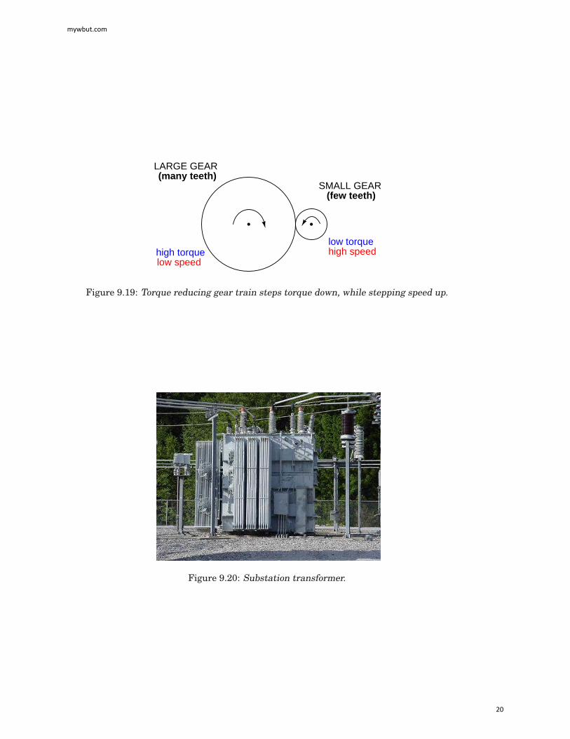
The step-up/step-down effect of coil turn ratios in a transformer (Figure 9.18) is analogousto gear tooth ratios in mechanical gear systems, transforming values of speed and torque inmuch the same way: (Figure 9.19)Step-up and step-down transformers for power distribution purposes can be gigantic in pro-
portion to the power transformers previously shown, some units standing as tall as a home.The following photograph shows a substation transformer standing about twelve feet tall: (Fig-ure 9.20)
mywbut.com
19
LARGE GEAR
SMALL GEAR(many teeth)
(few teeth)
high torquelow speed
low torquehigh speed
Figure 9.19: Torque reducing gear train steps torque down, while stepping speed up.
Figure 9.20: Substation transformer.
mywbut.com
20

• REVIEW:
• Transformers “step up” or “step down” voltage according to the ratios of primary to sec-ondary wire turns.
•
Voltage transformation ratio =Nsecondary
Nprimary
Current transformation ratio =Nprimary
Nsecondary
N = number of turns in winding
Where,
• A transformer designed to increase voltage from primary to secondary is called a step-up transformer. A transformer designed to reduce voltage from primary to secondary iscalled a step-down transformer.
• The transformation ratio of a transformer will be equal to the square root of its primaryto secondary inductance (L) ratio.
•Voltage transformation ratio =
Lsecondary
Lprimary
9.3 Electrical isolation
Aside from the ability to easily convert between different levels of voltage and current in ACand DC circuits, transformers also provide an extremely useful feature called isolation, whichis the ability to couple one circuit to another without the use of direct wire connections. We candemonstrate an application of this effect with another SPICE simulation: this time showing“ground” connections for the two circuits, imposing a high DC voltage between one circuit andground through the use of an additional voltage source:(Figure 9.21)
v1 1 0 ac 10 sinrbogus1 1 2 1e-12v2 5 0 dc 250l1 2 0 10000l2 3 5 100k l1 l2 0.999vi1 3 4 ac 0rload 4 5 1k.ac lin 1 60 60.print ac v(2,0) i(v1).print ac v(3,5) i(vi1).end
mywbut.com
21

(for SPICE to measure current)
0 V
1
0
2
0
3 4
5 5
0
Rbogus
V1 10 V L1 L2
10 kH 100 H
Vi1
Rload 1 kΩ
V2 250 V
Figure 9.21: Transformer isolates 10 Vac at V1 from 250 VDC at V2.
DC voltages referenced to ground (node 0):(1) 0.0000 (2) 0.0000 (3) 250.0000(4) 250.0000 (5) 250.0000AC voltages:freq v(2) i(v1)6.000E+01 1.000E+01 9.975E-05 Primary windingfreq v(3,5) i(vi1)6.000E+01 9.962E-01 9.962E-04 Secondary winding
mywbut.com
22

SPICE shows the 250 volts DC being impressed upon the secondary circuit elements withrespect to ground, (Figure 9.21) but as you can see there is no effect on the primary circuit (zeroDC voltage) at nodes 1 and 2, and the transformation of AC power from primary to secondarycircuits remains the same as before. The impressed voltage in this example is often called acommon-mode voltage because it is seen at more than one point in the circuit with referenceto the common point of ground. The transformer isolates the common-mode voltage so that itis not impressed upon the primary circuit at all, but rather isolated to the secondary side. Forthe record, it does not matter that the common-mode voltage is DC, either. It could be AC, evenat a different frequency, and the transformer would isolate it from the primary circuit all thesame.There are applications where electrical isolation is needed between two AC circuit without
any transformation of voltage or current levels. In these instances, transformers called isola-tion transformers having 1:1 transformation ratios are used. A benchtop isolation transformeris shown in Figure 9.22.
Figure 9.22: Isolation transformer isolates power out from the power line.
• REVIEW:
• By being able to transfer power from one circuit to another without the use of intercon-necting conductors between the two circuits, transformers provide the useful feature ofelectrical isolation.
• Transformers designed to provide electrical isolation without stepping voltage and cur-rent either up or down are called isolation transformers.
9.4 Phasing
Since transformers are essentially AC devices, we need to be aware of the phase relationshipsbetween the primary and secondary circuits. Using our SPICE example from before, we can
mywbut.com
23

plot the waveshapes (Figure 9.23) for the primary and secondary circuits and see the phaserelations for ourselves:
spice transient analysis file for use with nutmeg:transformerv1 1 0 sin(0 15 60 0 0)rbogus1 1 2 1e-12v2 5 0 dc 250l1 2 0 10000l2 3 5 100k l1 l2 0.999vi1 3 4 ac 0rload 4 5 1k.tran 0.5m 17m.endnutmeg commands:setplot tran1plot v(2) v(3,5)
Figure 9.23: Secondary voltage V(3,5) is in-phase with primary voltage V(2), and stepped downby factor of ten.
In going from primary, V(2), to secondary, V(3,5), the voltage was stepped down by a factorof ten, (Figure 9.23) , and the current was stepped up by a factor of 10. (Figure 9.24) Both
mywbut.com
24

current (Figure 9.24) and voltage (Figure 9.23) waveforms are in-phase in going from primaryto secondary.
nutmeg commands:setplot tran1plot I(L1#branch) I(L2#branch)
Figure 9.24: Primary and secondary currents are in-phase. Secondary current is stepped upby a factor of ten.
It would appear that both voltage and current for the two transformer windings are in-phase with each other, at least for our resistive load. This is simple enough, but it would benice to know which way we should connect a transformer in order to ensure the proper phaserelationships be kept. After all, a transformer is nothing more than a set of magnetically-linked inductors, and inductors don’t usually come with polarity markings of any kind. If wewere to look at an unmarked transformer, we would have no way of knowing which way to hookit up to a circuit to get in-phase (or 180o out-of-phase) voltage and current: (Figure 9.25)
+
-
+
- +
-
or ???
Figure 9.25: As a practical matter, the polarity of a transformer can be ambiguous.
mywbut.com
25

Since this is a practical concern, transformer manufacturers have come up with a sort ofpolarity marking standard to denote phase relationships. It is called the dot convention, andis nothing more than a dot placed next to each corresponding leg of a transformer winding:(Figure 9.26)
Figure 9.26: A pair of dots indicates like polarity.
Typically, the transformer will come with some kind of schematic diagram labeling the wireleads for primary and secondary windings. On the diagram will be a pair of dots similar towhat is seen above. Sometimes dots will be omitted, but when “H” and “X” labels are usedto label transformer winding wires, the subscript numbers are supposed to represent windingpolarity. The “1” wires (H1 and X1) represent where the polarity-marking dots would normallybe placed.The similar placement of these dots next to the top ends of the primary and secondary
windings tells us that whatever instantaneous voltage polarity seen across the primary wind-ing will be the same as that across the secondary winding. In other words, the phase shift fromprimary to secondary will be zero degrees.On the other hand, if the dots on each winding of the transformer do not match up, the
phase shift will be 180o between primary and secondary, like this: (Figure 9.27)
Figure 9.27: Out of phase: primary red to dot, secondary black to dot.
Of course, the dot convention only tells you which end of each winding is which, relative tothe other winding(s). If you want to reverse the phase relationship yourself, all you have to dois swap the winding connections like this: (Figure 9.28)
• REVIEW:
mywbut.com
26

Figure 9.28: In phase: primary red to dot, secondary red to dot.
• The phase relationships for voltage and current between primary and secondary circuitsof a transformer are direct: ideally, zero phase shift.
• The dot convention is a type of polarity marking for transformer windings showing whichend of the winding is which, relative to the other windings.
9.5 Winding configurations
Transformers are very versatile devices. The basic concept of energy transfer between mutualinductors is useful enough between a single primary and single secondary coil, but transform-ers don’t have to be made with just two sets of windings. Consider this transformer circuit:(Figure 9.29)
load #1
load #2
Figure 9.29: Transformer with multiple secondaries, provides multiple output voltages.
Here, three inductor coils share a common magnetic core, magnetically “coupling” or “link-ing” them together. The relationship of winding turn ratios and voltage ratios seen with asingle pair of mutual inductors still holds true here for multiple pairs of coils. It is entirelypossible to assemble a transformer such as the one above (one primary winding, two secondarywindings) in which one secondary winding is a step-down and the other is a step-up. In fact,this design of transformer was quite common in vacuum tube power supply circuits, whichwere required to supply low voltage for the tubes’ filaments (typically 6 or 12 volts) and highvoltage for the tubes’ plates (several hundred volts) from a nominal primary voltage of 110volts AC. Not only are voltages and currents of completely different magnitudes possible withsuch a transformer, but all circuits are electrically isolated from one another.
mywbut.com
27

Figure 9.30: Photograph of multiple-winding transformer with six windings, a primary andfive secondaries.
The transformer in Figure 9.30 is intended to provide both high and low voltages necessaryin an electronic system using vacuum tubes. Low voltage is required to power the filamentsof vacuum tubes, while high voltage is required to create the potential difference between theplate and cathode elements of each tube. One transformer with multiple windings sufficeselegantly to provide all the necessary voltage levels from a single 115 V source. The wires forthis transformer (15 of them!) are not shown in the photograph, being hidden from view.
If electrical isolation between secondary circuits is not of great importance, a similar effectcan be obtained by “tapping” a single secondary winding at multiple points along its length,like Figure 9.31.
load #1
load #2
Figure 9.31: A single tapped secondary provides multiple voltages.
A tap is nothing more than a wire connection made at some point on a winding betweenthe very ends. Not surprisingly, the winding turn/voltage magnitude relationship of a normaltransformer holds true for all tapped segments of windings. This fact can be exploited toproduce a transformer capable of multiple ratios: (Figure 9.32)
Carrying the concept of winding taps further, we end up with a “variable transformer,”
mywbut.com
28

load
multi-poleswitch
Figure 9.32: A tapped secondary using a switch to select one of many possible voltages.
where a sliding contact is moved along the length of an exposed secondary winding, able toconnect with it at any point along its length. The effect is equivalent to having a winding tapat every turn of the winding, and a switch with poles at every tap position: (Figure 9.33)
load
Variable transformer
Figure 9.33: A sliding contact on the secondary continuously varies the secondary voltage.
One consumer application of the variable transformer is in speed controls for model trainsets, especially the train sets of the 1950’s and 1960’s. These transformers were essentiallystep-down units, the highest voltage obtainable from the secondary winding being substan-tially less than the primary voltage of 110 to 120 volts AC. The variable-sweep contact provideda simple means of voltage control with little wasted power, much more efficient than controlusing a variable resistor!Moving-slide contacts are too impractical to be used in large industrial power transformer
designs, but multi-pole switches and winding taps are common for voltage adjustment. Adjust-ments need to be made periodically in power systems to accommodate changes in loads overmonths or years in time, and these switching circuits provide a convenient means. Typically,
mywbut.com
29

such “tap switches” are not engineered to handle full-load current, but must be actuated onlywhen the transformer has been de-energized (no power).Seeing as how we can tap any transformer winding to obtain the equivalent of several
windings (albeit with loss of electrical isolation between them), it makes sense that it should bepossible to forego electrical isolation altogether and build a transformer from a single winding.Indeed this is possible, and the resulting device is called an autotransformer: (Figure 9.34)
load
Autotransformer
Figure 9.34: This autotransformer steps voltage up with a single tapped winding, saving cop-per, sacrificing isolation.
The autotransformer depicted above performs a voltage step-up function. A step-down au-totransformer would look something like Figure 9.35.
load
Autotransformer
Figure 9.35: This auto transformer steps voltage down with a single copper-saving tappedwinding.
mywbut.com
30

Autotransformers find popular use in applications requiring a slight boost or reduction involtage to a load. The alternative with a normal (isolated) transformer would be to either havejust the right primary/secondary winding ratio made for the job or use a step-down configu-ration with the secondary winding connected in series-aiding (“boosting”) or series-opposing(“bucking”) fashion. Primary, secondary, and load voltages are given to illustrate how thiswould work.First, the “boosting” configuration. In Figure 9.36 the secondary coil’s polarity is oriented
so that its voltage directly adds to the primary voltage.
"boosting"
120 V 30 V 150 V
Figure 9.36: Ordinary transformer wired as an autotransformer to boost the line voltage.
Next, the “bucking” configuration. In Figure 9.37 the secondary coil’s polarity is oriented sothat its voltage directly subtracts from the primary voltage:
"bucking"
120 V 30 V 90 V
Figure 9.37: Ordinary transformer wired as an autotransformer to buck the line voltage down.
The prime advantage of an autotransformer is that the same boosting or bucking functionis obtained with only a single winding, making it cheaper and lighter to manufacture than aregular (isolating) transformer having both primary and secondary windings.Like regular transformers, autotransformer windings can be tapped to provide variations
in ratio. Additionally, they can be made continuously variable with a sliding contact to tapthe winding at any point along its length. The latter configuration is popular enough to haveearned itself its own name: the Variac. (Figure 9.38)Small variacs for benchtop use are popular pieces of equipment for the electronics experi-
menter, being able to step household AC voltage down (or sometimes up as well) with a wide,fine range of control by a simple twist of a knob.
mywbut.com
31

load
The "Variac"variable autotransformer
Figure 9.38: A variac is an autotransformer with a sliding tap.
• REVIEW:
• Transformers can be equipped with more than just a single primary and single secondarywinding pair. This allows for multiple step-up and/or step-down ratios in the same device.
• Transformer windings can also be “tapped:” that is, intersected at many points to seg-ment a single winding into sections.
• Variable transformers can be made by providing a movable arm that sweeps across thelength of a winding, making contact with the winding at any point along its length. Thewinding, of course, has to be bare (no insulation) in the area where the arm sweeps.
• An autotransformer is a single, tapped inductor coil used to step up or step down voltagelike a transformer, except without providing electrical isolation.
• A Variac is a variable autotransformer.
9.6 Voltage regulation
As we saw in a few SPICE analyses earlier in this chapter, the output voltage of a transformervaries some with varying load resistances, even with a constant voltage input. The degreeof variance is affected by the primary and secondary winding inductances, among other fac-tors, not the least of which includes winding resistance and the degree of mutual inductance(magnetic coupling) between the primary and secondary windings. For power transformer ap-plications, where the transformer is seen by the load (ideally) as a constant source of voltage,it is good to have the secondary voltage vary as little as possible for wide variances in loadcurrent.The measure of how well a power transformer maintains constant secondary voltage over a
range of load currents is called the transformer’s voltage regulation. It can be calculated fromthe following formula:
Regulation percentage =Eno-load - Efull-load
(100%)Efull-load
mywbut.com
32

“Full-load” means the point at which the transformer is operating at maximum permissiblesecondary current. This operating point will be determined primarily by the winding wiresize (ampacity) and the method of transformer cooling. Taking our first SPICE transformersimulation as an example, let’s compare the output voltage with a 1 kΩ load versus a 200 Ω
load (assuming that the 200 Ω load will be our “full load” condition). Recall if you will that ourconstant primary voltage was 10.00 volts AC:
freq v(3,5) i(vi1)6.000E+01 9.962E+00 9.962E-03 Output with 1k ohm loadfreq v(3,5) i(vi1)6.000E+01 9.348E+00 4.674E-02 Output with 200 ohm load
Notice how the output voltage decreases as the load gets heavier (more current). Now let’stake that same transformer circuit and place a load resistance of extremely high magnitudeacross the secondary winding to simulate a “no-load” condition: (See ”transformer” spice list”)
transformerv1 1 0 ac 10 sinrbogus1 1 2 1e-12rbogus2 5 0 9e12l1 2 0 100l2 3 5 100k l1 l2 0.999vi1 3 4 ac 0rload 4 5 9e12.ac lin 1 60 60.print ac v(2,0) i(v1).print ac v(3,5) i(vi1).end
freq v(2) i(v1)6.000E+01 1.000E+01 2.653E-04freq v(3,5) i(vi1)6.000E+01 9.990E+00 1.110E-12 Output with (almost) no load
So, we see that our output (secondary) voltage spans a range of 9.990 volts at (virtually) noload and 9.348 volts at the point we decided to call “full load.” Calculating voltage regulationwith these figures, we get:
Regulation percentage = (100%)9.990 V - 9.348 V
Regulation percentage = 6.8678 %
9.348 V
Incidentally, this would be considered rather poor (or “loose”) regulation for a power trans-former. Powering a simple resistive load like this, a good power transformer should exhibit
mywbut.com
33

a regulation percentage of less than 3%. Inductive loads tend to create a condition of worsevoltage regulation, so this analysis with purely resistive loads was a “best-case” condition.There are some applications, however, where poor regulation is actually desired. One such
case is in discharge lighting, where a step-up transformer is required to initially generate ahigh voltage (necessary to “ignite” the lamps), then the voltage is expected to drop off once thelamp begins to draw current. This is because discharge lamps’ voltage requirements tend to bemuch lower after a current has been established through the arc path. In this case, a step-uptransformer with poor voltage regulation suffices nicely for the task of conditioning power tothe lamp.Another application is in current control for AC arc welders, which are nothing more than
step-down transformers supplying low-voltage, high-current power for the welding process. Ahigh voltage is desired to assist in “striking” the arc (getting it started), but like the dischargelamp, an arc doesn’t require as much voltage to sustain itself once the air has been heated tothe point of ionization. Thus, a decrease of secondary voltage under high load current wouldbe a good thing. Some arc welder designs provide arc current adjustment by means of a mov-able iron core in the transformer, cranked in or out of the winding assembly by the operator.Moving the iron slug away from the windings reduces the strength of magnetic coupling be-tween the windings, which diminishes no-load secondary voltage andmakes for poorer voltageregulation.No exposition on transformer regulation could be called complete without mention of an un-
usual device called a ferroresonant transformer. “Ferroresonance” is a phenomenon associatedwith the behavior of iron cores while operating near a point of magnetic saturation (where thecore is so strongly magnetized that further increases in winding current results in little or noincrease in magnetic flux).While being somewhat difficult to describe without going deep into electromagnetic the-
ory, the ferroresonant transformer is a power transformer engineered to operate in a conditionof persistent core saturation. That is, its iron core is “stuffed full” of magnetic lines of fluxfor a large portion of the AC cycle so that variations in supply voltage (primary winding cur-rent) have little effect on the core’s magnetic flux density, which means the secondary windingoutputs a nearly constant voltage despite significant variations in supply (primary winding)voltage. Normally, core saturation in a transformer results in distortion of the sinewave shape,and the ferroresonant transformer is no exception. To combat this side effect, ferroresonanttransformers have an auxiliary secondary winding paralleled with one or more capacitors,forming a resonant circuit tuned to the power supply frequency. This “tank circuit” serves asa filter to reject harmonics created by the core saturation, and provides the added benefit ofstoring energy in the form of AC oscillations, which is available for sustaining output windingvoltage for brief periods of input voltage loss (milliseconds’ worth of time, but certainly betterthan nothing). (Figure 9.39)In addition to blocking harmonics created by the saturated core, this resonant circuit also
“filters out” harmonic frequencies generated by nonlinear (switching) loads in the secondarywinding circuit and any harmonics present in the source voltage, providing “clean” power tothe load.Ferroresonant transformers offer several features useful in AC power conditioning: con-
stant output voltage given substantial variations in input voltage, harmonic filtering betweenthe power source and the load, and the ability to “ride through” brief losses in power by keepinga reserve of energy in its resonant tank circuit. These transformers are also highly tolerant
mywbut.com
34

AC powerinput
AC poweroutput
Resonant LC circuit
Figure 9.39: Ferroresonant transformer provides voltage regulation of the output.
of excessive loading and transient (momentary) voltage surges. They are so tolerant, in fact,that some may be briefly paralleled with unsynchronized AC power sources, allowing a loadto be switched from one source of power to another in a “make-before-break” fashion with nointerruption of power on the secondary side!Unfortunately, these devices have equally noteworthy disadvantages: they waste a lot of
energy (due to hysteresis losses in the saturated core), generating significant heat in the pro-cess, and are intolerant of frequency variations, which means they don’t work very well whenpowered by small engine-driven generators having poor speed regulation. Voltages produced inthe resonant winding/capacitor circuit tend to be very high, necessitating expensive capacitorsand presenting the service technician with very dangerous working voltages. Some applica-tions, though, may prioritize the ferroresonant transformer’s advantages over its disadvan-tages. Semiconductor circuits exist to “condition” AC power as an alternative to ferroresonantdevices, but none can compete with this transformer in terms of sheer simplicity.
• REVIEW:
• Voltage regulation is the measure of how well a power transformer can maintain constantsecondary voltage given a constant primary voltage and wide variance in load current.The lower the percentage (closer to zero), the more stable the secondary voltage and thebetter the regulation it will provide.
• A ferroresonant transformer is a special transformer designed to regulate voltage at astable level despite wide variation in input voltage.
mywbut.com
35