transformer protector
TRANSCRIPT
TRANSFORMER PROTECTORThe only solution against transformer explosions
During a transformer short circuit, the TRANSFORMER PROTECTOR (TP) is activated within milliseconds by the first dynamic pressure peak of the shock
wave, avoiding transformer explosions before static pressure increases.
couv1et 4 8/08/08 10:56 Page 1
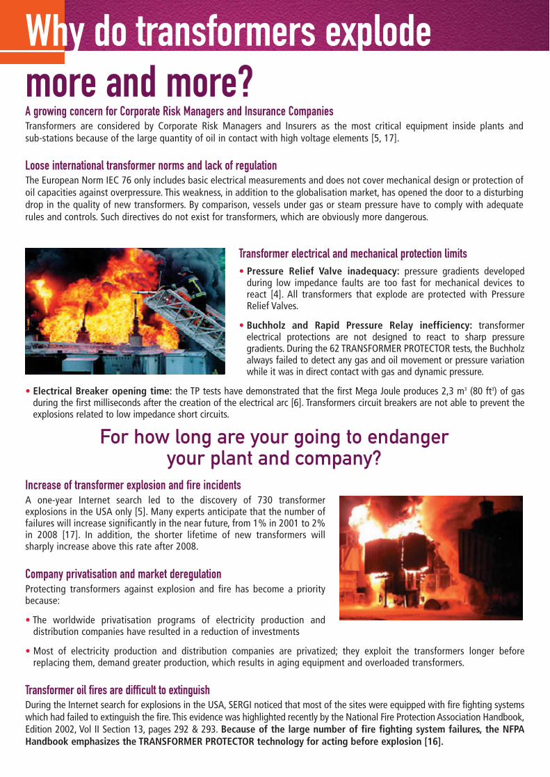
Why do transformers explode more and more?A growing concern for Corporate Risk Managers and Insurance CompaniesTransformers are considered by Corporate Risk Managers and Insurers as the most critical equipment inside plants and sub-stations because of the large quantity of oil in contact with high voltage elements [5, 17].
Loose international transformer norms and lack of regulationThe European Norm IEC 76 only includes basic electrical measurements and does not cover mechanical design or protection ofoil capacities against overpressure. This weakness, in addition to the globalisation market, has opened the door to a disturbingdrop in the quality of new transformers. By comparison, vessels under gas or steam pressure have to comply with adequaterules and controls. Such directives do not exist for transformers, which are obviously more dangerous.
Transformer electrical and mechanical protection limits• Pressure Relief Valve inadequacy: pressure gradients developed
during low impedance faults are too fast for mechanical devices toreact [4]. All transformers that explode are protected with PressureRelief Valves.
• Buchholz and Rapid Pressure Relay inefficiency: transformerelectrical protections are not designed to react to sharp pressuregradients. During the 62 TRANSFORMER PROTECTOR tests, the Buchholzalways failed to detect any gas and oil movement or pressure variationwhile it was in direct contact with gas and dynamic pressure.
• Electrical Breaker opening time: the TP tests have demonstrated that the first Mega Joule produces 2,3 m3 (80 ft3) of gasduring the first milliseconds after the creation of the electrical arc [6]. Transformers circuit breakers are not able to prevent theexplosions related to low impedance short circuits.
Increase of transformer explosion and fire incidentsA one-year Internet search led to the discovery of 730 transformerexplosions in the USA only [5]. Many experts anticipate that the number offailures will increase significantly in the near future, from 1% in 2001 to 2%in 2008 [17]. In addition, the shorter lifetime of new transformers willsharply increase above this rate after 2008.
Company privatisation and market deregulationProtecting transformers against explosion and fire has become a prioritybecause:
• The worldwide privatisation programs of electricity production anddistribution companies have resulted in a reduction of investments
• Most of electricity production and distribution companies are privatized; they exploit the transformers longer beforereplacing them, demand greater production, which results in aging equipment and overloaded transformers.
Transformer oil fires are difficult to extinguishDuring the Internet search for explosions in the USA, SERGI noticed that most of the sites were equipped with fire fighting systemswhich had failed to extinguish the fire. This evidence was highlighted recently by the National Fire Protection Association Handbook,Edition 2002, Vol II Section 13, pages 292 & 293. Because of the large number of fire fighting system failures, the NFPAHandbook emphasizes the TRANSFORMER PROTECTOR technology for acting before explosion [16].
For how long are your going to endanger your plant and company?
intérieur NOUVELLE VERSION - JUIN 2008 8/08/08 10:44 Page 1
Damage cost due to transformer explosions and fireSERGI has published a synthesis on the damage cost of transformer explosions [5]. The financial consequences often reachhundreds of USD Millions. Transformer explosions and fire provoke important lack of income, require replacement oftransformers and surrounding equipment, pollute the environment and convey bad publicity for the affected company. Thedamage caused depends on the transformer location:• Power plant incidents result in very high loss of revenue and can lead to company bankruptcies if not insured. For insurers,
the cost reference for transformer explosion and fire in a power plant is 0.5 USD Million per Mega Watt.• Transmission substation incidents can result in the complete blackout of a region or a country. Several well-known cases
have been recorded recently (USA, UK, Italy, Spain, France, etc.).• Distribution transformer explosions in urban areas can have
disastrous financial consequences, up to USD billion, because ofpollution and litigation costs.
The TRANSFORMER PROTECTOR acts before any damage is done Purchasing the TRANSFORMER PROTECTOR:
• Saves all equipment and buildings, since the explosive gases arechannelled far away
• Enables the quick internal repair of the transformer and reducessharply plant outages
• Leaves the environment unharmed.
The TRANSFORMER PROTECTOR is the sole existingtechnique able to sharply reduce transformer low
impedance faults consequences.
Why choose the Transformer Protector?
3
The TRANSFORMER PROTECTOR Financial Benefit is outstanding [5]Details of the TRANSFORMER PROTECTOR Financial Benefit are presented in Document [5]. To assess a technology for equipmentprotection, Corporate Risk Managers and Insurers use the following parameters:• MLEB (Maximum Loss Expectancy Before) is the cost of the worst recorded incident before
installing a protection• LEA (Loss Expectancy After) represents the evaluation of the damage cost of the worst
recorded incident with the chosen protection after installation• CTC (Cost to Complete) is the complete price of the protection, including erection, tests and
commissioning.
The Protection Financial Benefit (PFB) is a ratio between the protection price (CTC) and the damage cost reduction (MLEB - LEA):PFB = CTC / (MLEB-LEA)
For Corporate Risk Managers and Insurers, if:• PFB < 1%, the protective technology is strongly recommended• 1% ≤ PFB ≤ 4%, insurance companies adjust their rates and premiums.For the four incidents analysed in the publication [5], calculations have shown that the TRANSFORMER PROTECTOR Financial Benefitwas far below the 1% criterion with ratios ranging from 0.015% to 0.06%.
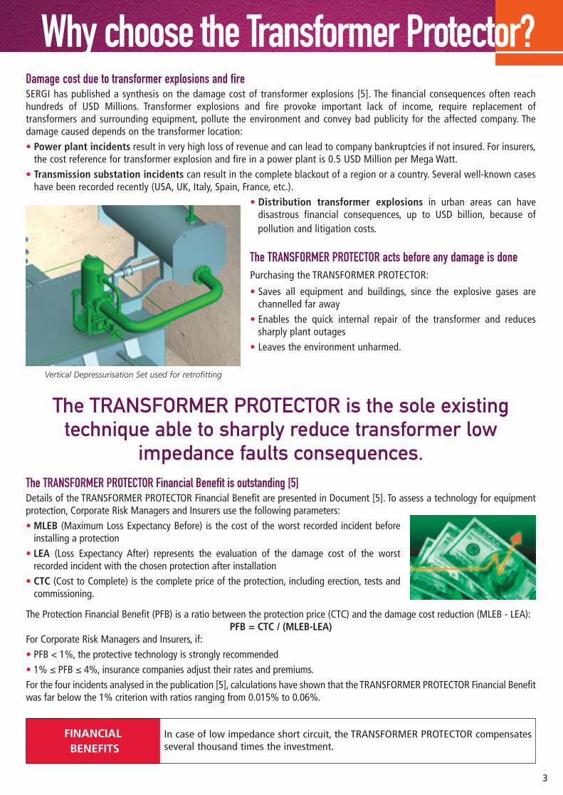
Vertical Depressurisation Set used for retrofitting
In case of low impedance short circuit, the TRANSFORMER PROTECTOR compensatesseveral thousand times the investment.
FINANCIALBENEFITS
intérieur NOUVELLE VERSION - JUIN 2008 8/08/08 10:44 Page 2
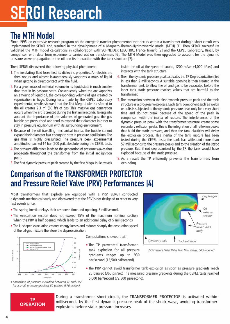
Comparison of the TRANSFORMER PROTECTOR and Pressure Relief Valve (PRV) Performances [4]Most transformers that explode are equipped with a PRV. SERGI conducteda dynamic mechanical study and discovered that the PRV is not designed to react to veryfast events since:
• The spring inertia delays their response time and opening, 5 milliseconds
• The evacuation section does not exceed 15% of the maximum nominal section when the PRV is half opened, which leads to an additional delay of 5 milliseconds
• The U-shaped evacuation creates energy losses and reduces sharply the evacuation speedof the oil-gas mixture therefore the depressurisation.
Computations showed that:
• The TP prevented transformertank explosion for all pressuregradients ranges up to 930bar/second (13,500 psi/second)
• The PRV cannot avoid transformer tank explosion as soon as pressure gradients reach 25 bar/sec (360 psi/sec) The measured pressure gradients during the CEPEL tests reached5,000 bar/second (72,500 psi/second).
The MTH ModelSince 1995, an extensive research program on the energetic transfer phenomenon that occurs within a transformer during a short-circuit wasimplemented by SERGI and resulted in the development of a Magneto-Thermo-Hydrodynamic model (MTH) [1]. Then SERGI successfullyvalidated the MTH model calculations in collaboration with SCHNEIDER ELECTRIC, France Transfo [2] and the CEPEL Laboratory, Brazil, bycomparison with data from experiments carried out on transformers [6]. The MTH Model was then upgraded to account for the dynamicpressure wave propagation in the oil and its interaction with the tank structure [7].
Then, SERGI discovered the following physical phenomena:
1. The insulating fluid loses first its dielectric properties. An electric arcthen occurs and almost instantaneously vaporizes a mass of liquidwhen getting in direct contact with the fluid.
2. For a given mass of material, volume in its liquid state is much smallerthan that in its gaseous state. Consequently, when the arc vaporizesan amount of liquid oil, the corresponding volume of gas created byvaporization is huge. During tests made by the CEPEL Laboratoryexperimental, results showed that the first Mega Joule transferred tothe oil creates 2.3 m3 (80 ft3) of gas. This massive gas generationoccurs when the arc is created during the first milliseconds.Taking intoaccount the importance of the volumes of generated gas, the gasbubble are pressurised and tend to expand their diameter in order tostay in pressure equilibrium with its surrounding environment.
3. Because of the oil travelling mechanical inertia, the bubble cannotexpand their diameter fast enough to stay in pressure equilibrium.Thegas thus is highly pressurized. The pressure peak experimentalamplitudes reached 14 bar (200 psi), absolute during the CEPEL tests.
4. The pressure difference leads to the generation of pressure waves thatpropagate throughout the transformer from the initial arc ignitionpoint.
5. The first dynamic pressure peak created by the first Mega Joule travels
inside the oil at the speed of sound, 1200 m/sec (4,000 ft/sec) andinteracts with the tank structure.
6. Then, the dynamic pressure peak activates the TP Depressurization Setin less than 2 milliseconds. A suitable opening is then created in thetransformer tank to allow the oil and gas to be evacuated before theinner tank static pressure reaches values that are harmful to thetransformer.
7. The interaction between the first dynamic pressure peak and the tankstructure is a progressive process. Each tank component such as weldsor bolts is subjected to the dynamic pressure peak only for a very shorttime and do not break because of the speed of the peak incomparison with the inertia of rupture. The interferences of thedynamic pressure peak with the transformer structure create somesecondary reflexion peaks.This is the integration of all reflexion peaksthat build the static pressure, and then the tank elasticity will delaythe explosion process. This inertia of the tank rupture has been tested during the CEPEL tests; the tank has withstood more than 57 milliseconds to the pressure peaks and to the creation of the staticpressure. But, if not depressurized by the TP, the tank would haveexploded because of the static pressure.
8. As a result the TP efficiently prevents the transformers fromexploding.
Diaphragm
Oil exhaust section
Pressure Relief ValveBody
Symmetry axis Fluid entrance
SERGI Research
200 210 220 230 240 250 260 270 2800
1
2
3
4
5
0
10
20
30
40
50
60
70
Pre
ssur
e in
bar
Time in ms
Pre
ssur
e in
psi
With a 6" TP With a 6" Pressure Relief Valve Without protection Pressure limit
Comparison of pressure evolution between TP and PRVfor a small pressure gradient 60 bar/sec (870 psi/sec)
2-D Pressure Relief Valve fluid flow image, 60% opened
During a transformer short circuit, the TRANSFORMER PROTECTOR is activated within milliseconds by the first dynamic pressure peak of the shock wave, avoiding transformer explosions before static pressure increases.
TP OPERATION
4
intérieur NOUVELLE VERSION - JUIN 2008 8/08/08 10:44 Page 3
The CEPEL Test Certificate stated that no permanent deformation have been noticed on the 3 tanks, despite 10 tests performed per tank, pressure gradients up to 4,000 bar/sec (58,000 psi/sec) and accelerations up to 400g.
Power Plant Transformers [3]Due to the generator inertia, power plant transformers suffer harsher fault conditions than transmission and distribution transformers.Therefore, SERGI decided to investigate the explosion of a power plant step-up transformer to design a TP capable of preventing any kind ofincident on any kind of transformer.In 2001, during this investigation, SERGI discovered for the first time that electrical arcs inside transformer oil could produce pressure gradientsfrom 300 to 930 bar/sec (4,300 up to 13,500 psi/sec).
Pressure Wave Propagation Modelling [7]To accurately compute the pressure wave propagation inside a transformer tank, the MTH model is based on:• A theoretical description of the gas and the liquid oil as compressible media• A robust and accurate numerical tool to solve the complex physical model equations on complex transformer geometries.Various configurations can thus be defined and numerically tested. Various physical effects can be accounted for.This numerical tool also enables the accurate computation of the pressure wave (dynamic pressure) interaction with the tank structure.
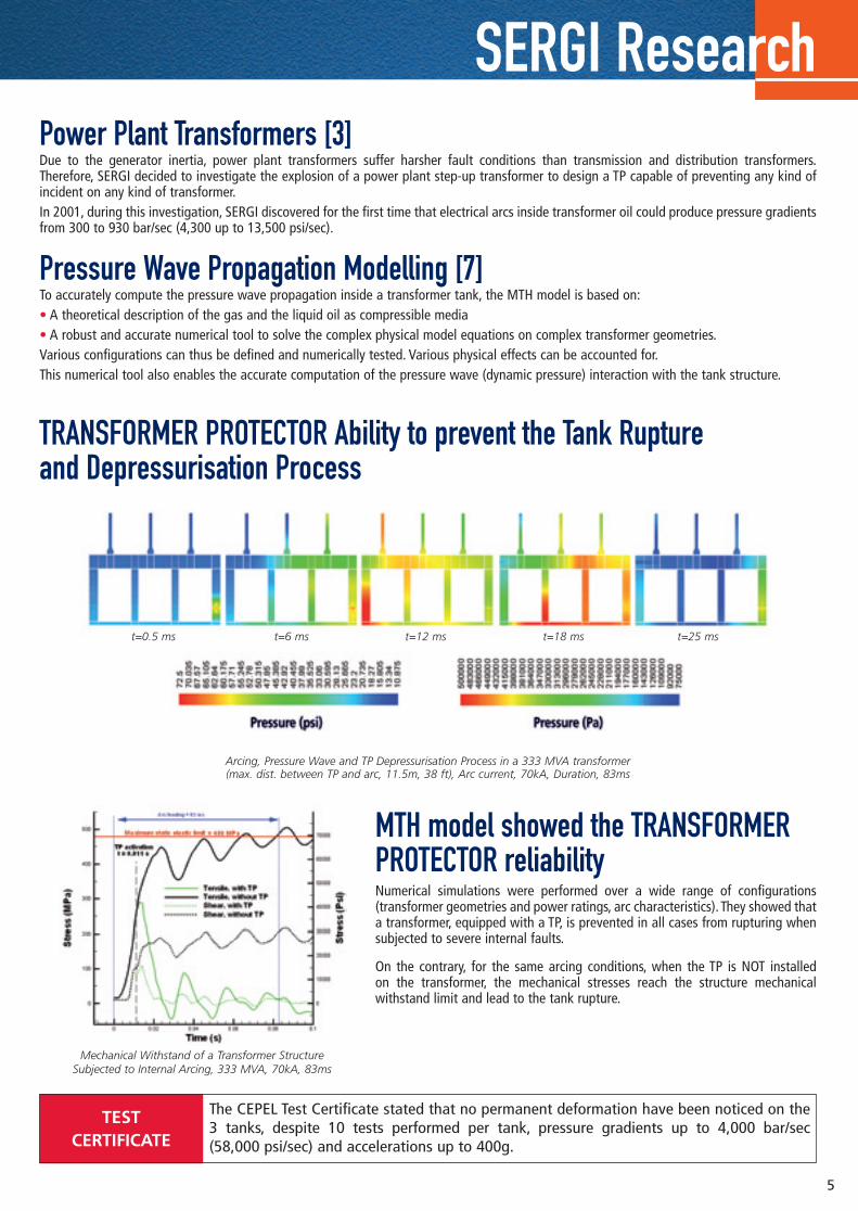
TRANSFORMER PROTECTOR Ability to prevent the Tank Rupture and Depressurisation Process
MTH model showed the TRANSFORMERPROTECTOR reliabilityNumerical simulations were performed over a wide range of configurations(transformer geometries and power ratings, arc characteristics). They showed thata transformer, equipped with a TP, is prevented in all cases from rupturing whensubjected to severe internal faults.
On the contrary, for the same arcing conditions, when the TP is NOT installed on the transformer, the mechanical stresses reach the structure mechanicalwithstand limit and lead to the tank rupture.
SERGI Research
TEST CERTIFICATE
5
t=0.5 ms t=6 ms t=12 ms t=18 ms t=25 ms
Arcing, Pressure Wave and TP Depressurisation Process in a 333 MVA transformer (max. dist. between TP and arc, 11.5m, 38 ft), Arc current, 70kA, Duration, 83ms
Mechanical Withstand of a Transformer Structure Subjected to Internal Arcing, 333 MVA, 70kA, 83ms
intérieur NOUVELLE VERSION - JUIN 2008 8/08/08 10:44 Page 4
RESULTS [6]A. Arc energy and transformer powerare not key parameters for transformertank explosion prevention
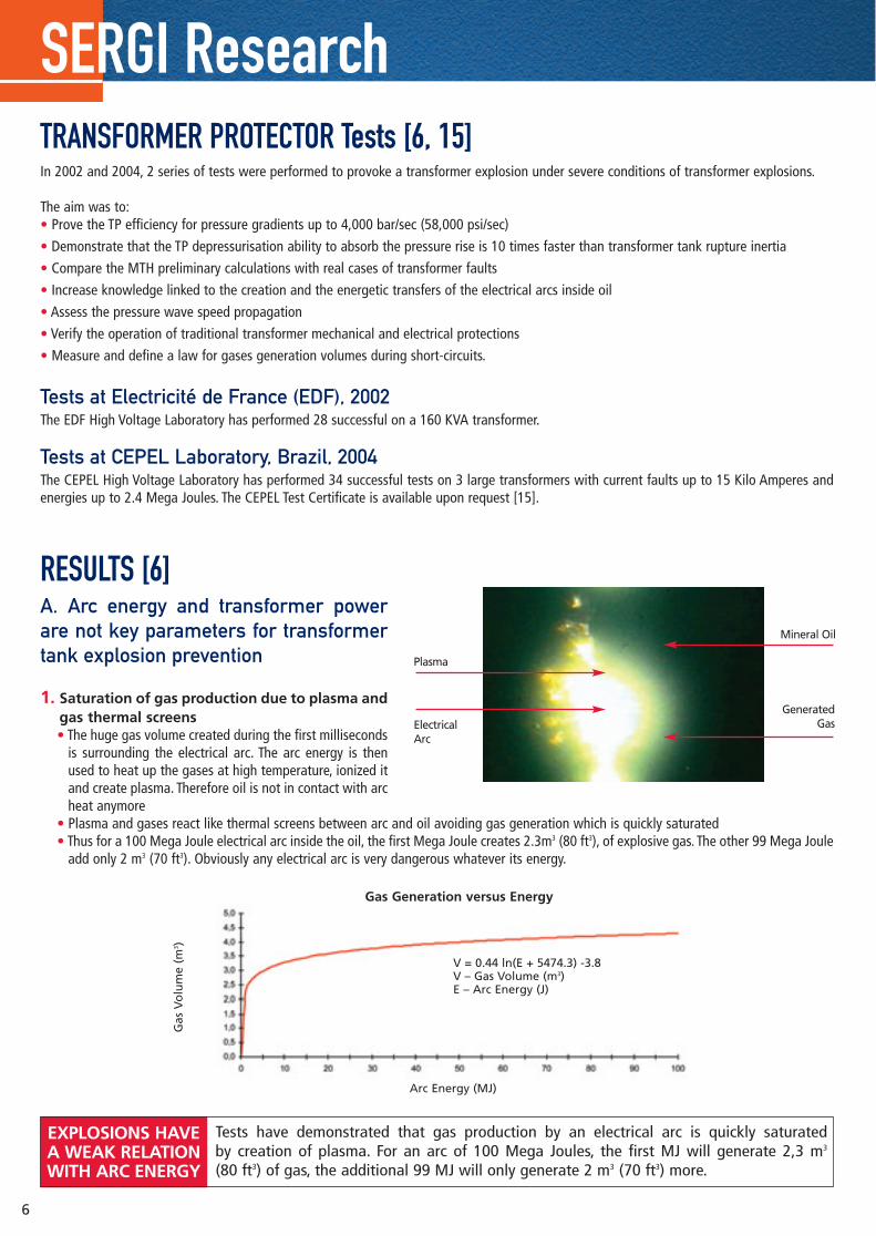
1. Saturation of gas production due to plasma andgas thermal screens• The huge gas volume created during the first milliseconds
is surrounding the electrical arc. The arc energy is thenused to heat up the gases at high temperature, ionized itand create plasma. Therefore oil is not in contact with archeat anymore
• Plasma and gases react like thermal screens between arc and oil avoiding gas generation which is quickly saturated• Thus for a 100 Mega Joule electrical arc inside the oil, the first Mega Joule creates 2.3m3 (80 ft3), of explosive gas. The other 99 Mega Joule
add only 2 m3 (70 ft3). Obviously any electrical arc is very dangerous whatever its energy.
TRANSFORMER PROTECTOR Tests [6, 15]In 2002 and 2004, 2 series of tests were performed to provoke a transformer explosion under severe conditions of transformer explosions.
The aim was to:• Prove the TP efficiency for pressure gradients up to 4,000 bar/sec (58,000 psi/sec)
• Demonstrate that the TP depressurisation ability to absorb the pressure rise is 10 times faster than transformer tank rupture inertia
• Compare the MTH preliminary calculations with real cases of transformer faults
• Increase knowledge linked to the creation and the energetic transfers of the electrical arcs inside oil
• Assess the pressure wave speed propagation
• Verify the operation of traditional transformer mechanical and electrical protections
• Measure and define a law for gases generation volumes during short-circuits.
Tests at Electricité de France (EDF), 2002The EDF High Voltage Laboratory has performed 28 successful on a 160 KVA transformer.
Tests at CEPEL Laboratory, Brazil, 2004The CEPEL High Voltage Laboratory has performed 34 successful tests on 3 large transformers with current faults up to 15 Kilo Amperes andenergies up to 2.4 Mega Joules. The CEPEL Test Certificate is available upon request [15].
SERGI Research
Tests have demonstrated that gas production by an electrical arc is quickly saturated by creation of plasma. For an arc of 100 Mega Joules, the first MJ will generate 2,3 m3
(80 ft3) of gas, the additional 99 MJ will only generate 2 m3 (70 ft3) more.
EXPLOSIONS HAVE A WEAK RELATION WITH ARC ENERGY
Mineral Oil
GeneratedGas
Plasma
ElectricalArc
6
Gas Generation versus Energy
Arc Energy (MJ)
Gas
Vo
lum
e (m
3 )
V = 0.44 ln(E + 5474.3) -3.8V – Gas Volume (m3)E – Arc Energy (J)
intérieur NOUVELLE VERSION - JUIN 2008 8/08/08 10:44 Page 5
2. Relation between electrical arc energy and dynamic pressure peak• One Mega Joule creates 2.3m3 (80 ft3) of explosive gas
• 100 Mega Joule create only a total of 4.3m3 (150 ft3) of explosive gas
• The tests have not shown a clear relation between electrical arc energy and maximum dynamic pressure peak
100 Kilo Joules can generate a peak of 10 bar (145 psi)
1 000 Kilo Joules can generate a peak of 3 bar (43 psi).
3. Conclusion: Transformer explosions have a weak connection with arc energy and transformer power
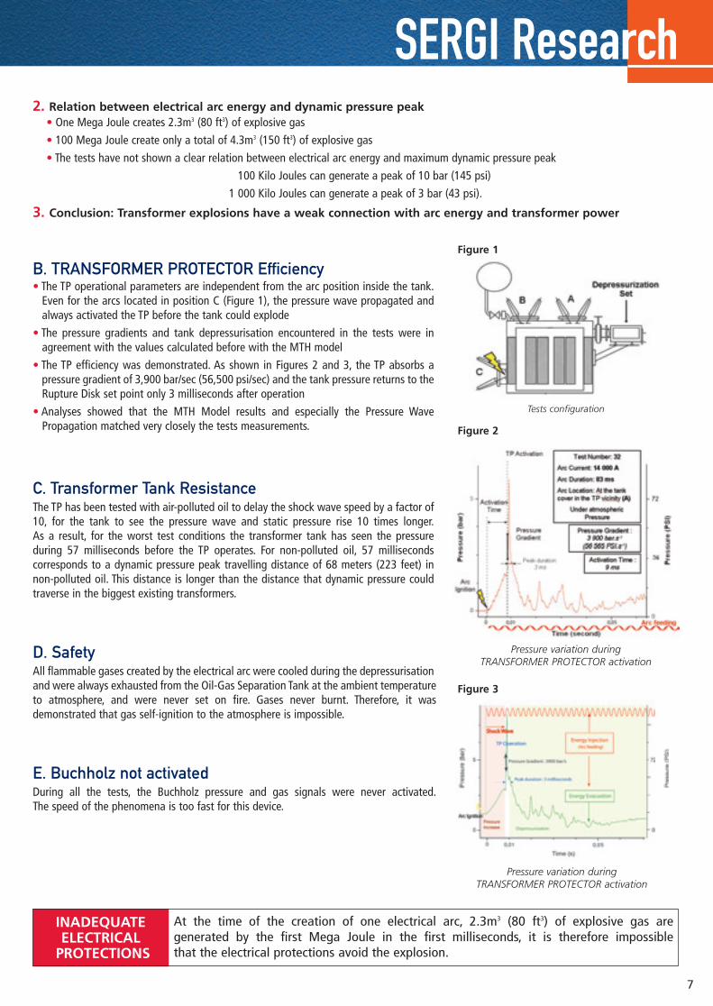
B. TRANSFORMER PROTECTOR Efficiency• The TP operational parameters are independent from the arc position inside the tank.
Even for the arcs located in position C (Figure 1), the pressure wave propagated andalways activated the TP before the tank could explode
• The pressure gradients and tank depressurisation encountered in the tests were inagreement with the values calculated before with the MTH model
• The TP efficiency was demonstrated. As shown in Figures 2 and 3, the TP absorbs apressure gradient of 3,900 bar/sec (56,500 psi/sec) and the tank pressure returns to theRupture Disk set point only 3 milliseconds after operation
• Analyses showed that the MTH Model results and especially the Pressure WavePropagation matched very closely the tests measurements.
C. Transformer Tank ResistanceThe TP has been tested with air-polluted oil to delay the shock wave speed by a factor of10, for the tank to see the pressure wave and static pressure rise 10 times longer.As a result, for the worst test conditions the transformer tank has seen the pressureduring 57 milliseconds before the TP operates. For non-polluted oil, 57 millisecondscorresponds to a dynamic pressure peak travelling distance of 68 meters (223 feet) innon-polluted oil. This distance is longer than the distance that dynamic pressure couldtraverse in the biggest existing transformers.
D. SafetyAll flammable gases created by the electrical arc were cooled during the depressurisationand were always exhausted from the Oil-Gas Separation Tank at the ambient temperatureto atmosphere, and were never set on fire. Gases never burnt. Therefore, it wasdemonstrated that gas self-ignition to the atmosphere is impossible.
E. Buchholz not activatedDuring all the tests, the Buchholz pressure and gas signals were never activated.The speed of the phenomena is too fast for this device.
SERGI Research
Pressure variation during TRANSFORMER PROTECTOR activation
Tests configuration
Figure 1
Figure 2
Figure 3
At the time of the creation of one electrical arc, 2.3m3 (80 ft3) of explosive gas are generated by the first Mega Joule in the first milliseconds, it is therefore impossible that the electrical protections avoid the explosion.
INADEQUATE ELECTRICAL
PROTECTIONS
7
Pressure variation during TRANSFORMER PROTECTOR activation
intérieur NOUVELLE VERSION - JUIN 2008 8/08/08 10:44 Page 6
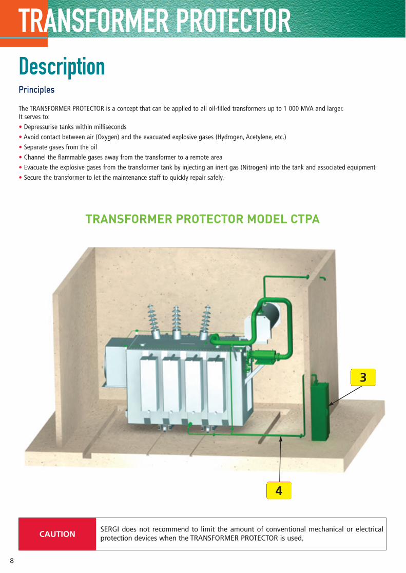
TRANSFORMER PROTECTORDescriptionPrinciples
The TRANSFORMER PROTECTOR is a concept that can be applied to all oil-filled transformers up to 1 000 MVA and larger.It serves to:
• Depressurise tanks within milliseconds
• Avoid contact between air (Oxygen) and the evacuated explosive gases (Hydrogen, Acetylene, etc.)
• Separate gases from the oil
• Channel the flammable gases away from the transformer to a remote area
• Evacuate the explosive gases from the transformer tank by injecting an inert gas (Nitrogen) into the tank and associated equipment
• Secure the transformer to let the maintenance staff to quickly repair safely.
3
SERGI does not recommend to limit the amount of conventional mechanical or electricalprotection devices when the TRANSFORMER PROTECTOR is used.CAUTION
8
TRANSFORMER PROTECTOR MODEL CTPA
4
intérieur NOUVELLE VERSION - JUIN 2008 8/08/08 10:44 Page 7
The SERGI Insurance Company covers the TP in case of malfunction during its whole operational life. The current coverage, Euro 3 Millions, increases yearly because the TP neverfailed. The TP coverage is often better than transformer manufacturer’s.
9
TRANSFORMER PROTECTOR
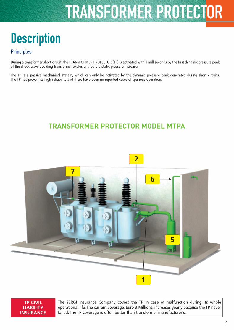
TRANSFORMER PROTECTOR MODEL MTPA
DescriptionPrinciples
During a transformer short circuit, the TRANSFORMER PROTECTOR (TP) is activated within milliseconds by the first dynamic pressure peakof the shock wave avoiding transformer explosions, before static pressure increases.
The TP is a passive mechanical system, which can only be activated by the dynamic pressure peak generated during short circuits.The TP has proven its high reliability and there have been no reported cases of spurious operation.
TP CIVILLIABILITY
INSURANCE
6
1
2
7
5
intérieur NOUVELLE VERSION - JUIN 2008 8/08/08 10:44 Page 8
TRANSFORMER PROTECTOR
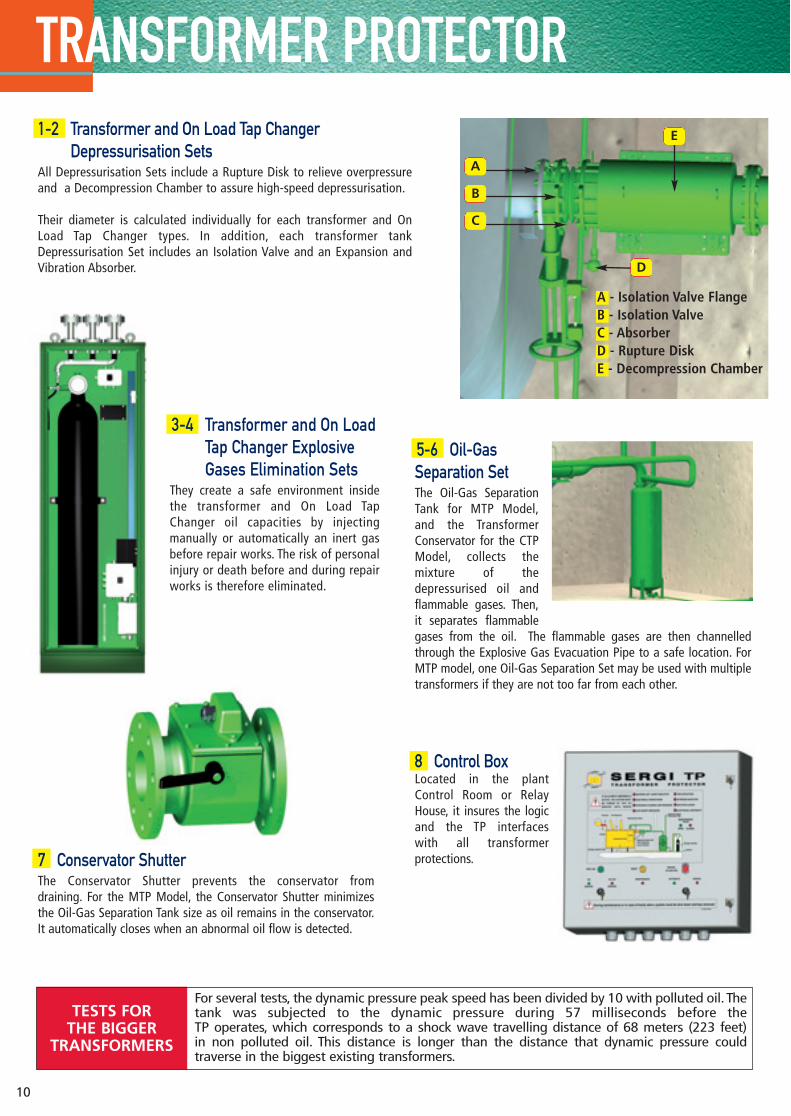
10
5-6 Oil-GasSeparation SetThe Oil-Gas SeparationTank for MTP Model,and the TransformerConservator for the CTPModel, collects themixture of thedepressurised oil andflammable gases. Then,it separates flammablegases from the oil. The flammable gases are then channelledthrough the Explosive Gas Evacuation Pipe to a safe location. ForMTP model, one Oil-Gas Separation Set may be used with multipletransformers if they are not too far from each other.
1-2 Transformer and On Load Tap ChangerDepressurisation Sets
All Depressurisation Sets include a Rupture Disk to relieve overpressureand a Decompression Chamber to assure high-speed depressurisation.
Their diameter is calculated individually for each transformer and OnLoad Tap Changer types. In addition, each transformer tankDepressurisation Set includes an Isolation Valve and an Expansion andVibration Absorber.
7 Conservator ShutterThe Conservator Shutter prevents the conservator from draining. For the MTP Model, the Conservator Shutter minimizesthe Oil-Gas Separation Tank size as oil remains in the conservator.It automatically closes when an abnormal oil flow is detected.
A - Isolation Valve FlangeB - Isolation ValveC - AbsorberD - Rupture DiskE - Decompression Chamber
A
B
C
D
E
For several tests, the dynamic pressure peak speed has been divided by 10 with polluted oil. Thetank was subjected to the dynamic pressure during 57 milliseconds before the TP operates, which corresponds to a shock wave travelling distance of 68 meters (223 feet) in non polluted oil. This distance is longer than the distance that dynamic pressure could traverse in the biggest existing transformers.
TESTS FOR THE BIGGER
TRANSFORMERS
8 Control BoxLocated in the plantControl Room or RelayHouse, it insures the logicand the TP interfaces with all transformerprotections.
3-4 Transformer and On Load Tap Changer Explosive Gases Elimination Sets
They create a safe environment insidethe transformer and On Load TapChanger oil capacities by injectingmanually or automatically an inert gasbefore repair works. The risk of personalinjury or death before and during repairworks is therefore eliminated.
intérieur NOUVELLE VERSION - JUIN 2008 8/08/08 10:44 Page 9
Different applications
11
Cost Benefit• Avoids oil fire to transformer and surrounding equipment
• Allows transformer repair after internal fault
• Render impossible environmental pollution by containing the oil in the OGST
• Eliminates risk to human life
• Reduces the downtime associated with transformerreplacement
• Decreases the high costs associated with purchasingreplacement power
• Eliminates disastrous public relations issues.
Applications For all transformers up to 1 000 MVA or above, located in:
• Power plants and any industrial site whose production couldbe affected by the loss of a transformer
• All the transmission and distribution substations
• Industrial plants with high explosion risks (oil refineries,offshore plants, mines)
• Environmental sensitive areas
• Sites not equipped with firewalls and/or Oil Storage Pits as the TP is the sole technology able to secure existinginstallations at low price.
CTP and MTP Models
STP Model
Differences with the CTP and MTP ModelsThe STP Model only protects small transformers. In this configuration, the Oil-Gas Separation Tank is used as aDecompression Chamber called Depressurisation and Oil and GasSeparation Tank. The STP Model Decompression Chamber will alsoperform the Oil and Gas Separation function, as shown on the picture beside. In most of the STP Model arrangements,there is no Isolation Valve, no Absorber and no ConservatorShutter.
Applications For all small indoor transformers from 0.5 to 5 MVA such as:
• Residential and office buildings
• Schools, universities, hotels, airports, hospitals
• Underground substations
• Industrial plants with high explosion risks (oil refineries, offshoreplants, mines)
• Railway network power supply stations
• Environmental sensitive areas.
During a transformer short circuit, the TRANSFORMER PROTECTOR (TP) is activated withinmilliseconds by the first dynamic pressure peak of the shock wave, avoiding transformerexplosions before static pressure increases.
PRINCIPLE
intérieur NOUVELLE VERSION - JUIN 2008 8/08/08 10:44 Page 10
Logic Diagram
12
Customers can choose between manual or automatic Nitrogen injection to eliminate explosive gases from the tank after the incident. This avoids fire or the bazooka effectcaused when the remaining explosive gas comes in contact with air during transformerrepair.
PEOPLE SAFETY
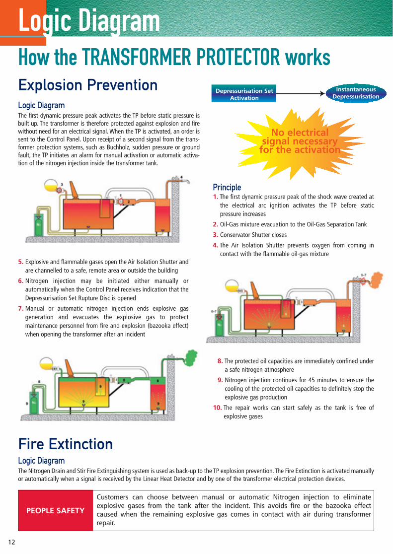
Explosion PreventionLogic DiagramThe first dynamic pressure peak activates the TP before static pressure isbuilt up. The transformer is therefore protected against explosion and firewithout need for an electrical signal. When the TP is activated, an order issent to the Control Panel. Upon receipt of a second signal from the trans-former protection systems, such as Buchholz, sudden pressure or groundfault, the TP initiates an alarm for manual activation or automatic activa-tion of the nitrogen injection inside the transformer tank.
Fire ExtinctionLogic DiagramThe Nitrogen Drain and Stir Fire Extinguishing system is used as back-up to the TP explosion prevention.The Fire Extinction is activated manuallyor automatically when a signal is received by the Linear Heat Detector and by one of the transformer electrical protection devices.
Principle1. The first dynamic pressure peak of the shock wave created at
the electrical arc ignition activates the TP before staticpressure increases
2. Oil-Gas mixture evacuation to the Oil-Gas Separation Tank
3. Conservator Shutter closes
4. The Air Isolation Shutter prevents oxygen from coming incontact with the flammable oil-gas mixture
5. Explosive and flammable gases open the Air Isolation Shutter andare channelled to a safe, remote area or outside the building
6. Nitrogen injection may be initiated either manually orautomatically when the Control Panel receives indication that theDepressurisation Set Rupture Disc is opened
7. Manual or automatic nitrogen injection ends explosive gasgeneration and evacuates the explosive gas to protectmaintenance personnel from fire and explosion (bazooka effect)when opening the transformer after an incident
8. The protected oil capacities are immediately confined undera safe nitrogen atmosphere
9. Nitrogen injection continues for 45 minutes to ensure thecooling of the protected oil capacities to definitely stop theexplosive gas production
10. The repair works can start safely as the tank is free ofexplosive gases
How the TRANSFORMER PROTECTOR worksDepressurisation Set
Activation
No electrical signal necessary
for the activation
InstantaneousDepressurisation
intérieur NOUVELLE VERSION - JUIN 2008 8/08/08 10:44 Page 11
Adaptation to transformers
13
When the TRANSFORMER PROTECTOR is retrofitted on service transformers, existing interfaces are always used, tank drilling and machining are never necessary.TP RETROFITTING
For existing transformers [11]Document [11] details every possible configuration for adaptation on transformers already in service.
SERGI always uses existing transformer interfaces in order to avoid tank drilling and machining.Oil sampling or filtering valves at the bottom of the tank perfectly fit to inject nitrogen inside the transformer. In that case, T-pieces are used.
Installation [12]The ControlPanel ismounted inthe controlroom or relayhouse.TheNitrogenCabinetshould bemountedclose to thetransformer.
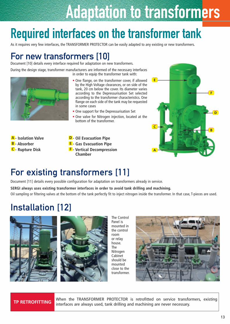
Required interfaces on the transformer tankAs it requires very few interfaces, the TRANSFORMER PROTECTOR can be easily adapted to any existing or new transformers.
For new transformers [10]Document [10] details every interface required for adaptation on new transformers.
During the design stage, transformer manufacturers are informed of the necessary interfacesin order to equip the transformer tank with:
• One flange, on the transformer cover, if allowedby the High Voltage clearances, or on side of thetank, 20 cm below the cover. Its diameter variesaccording to the Depressurisation Set selectedaccording to the transformer characteristics. Oneflange on each side of the tank may be requestedin some cases
• One support for the Depressurisation Set• One valve for Nitrogen injection, located at the
bottom of the transformer.
- Isolation Valve- Absorber- Rupture Disk
- Oil Evacuation Pipe- Gas Evacuation Pipe- Vertical Decompression
ChamberFED
CBA
BC
A
D
E
F
intérieur NOUVELLE VERSION - JUIN 2008 8/08/08 10:45 Page 12
Optional items • Adaptation for OLTC oil filtration unit• Autonomous dry battery with associated low charge alarm• Depressurization chamber heater for very cold climates• Manual Valve for nitrogen injection from the cylinder• Insulating flanges for transformers protected with earth fault• Cabinet local alarm after TP activation• Cabinet hydrostat for humid countries• Explosive Gas Collector for Analysis after short circuit• Ethernet connection with SCADA• Engineering and on site drawings (Solidworks)• Control Box Rack• Cabinet internal lighting• Numerous other options are available on request TRANSFORMER PROTECTOR MTPA3B Model protecting tank, 1 OLTC and 3 OCBs
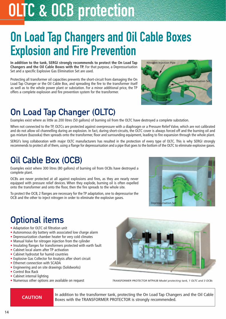
In addition to the tank, SERGI strongly recommends to protect the On Load TapChangers and the Oil Cable Boxes with the TP. For that purpose, a DepressurisationSet and a specific Explosive Gas Elimination Set are used.
Protecting all transformer oil capacities prevents the short-circuit from damaging the OnLoad Tap Changer or the Oil Cable Box, and spreading the fire to the transformer itselfas well as to the whole power plant or substation. For a minor additional price, the TPoffers a complete explosion and fire prevention system for the transformer.
On Load Tap Changer (OLTC)Examples exist where as little as 200 litres (50 gallons) of burning oil from the OLTC have destroyed a complete substation.
When not connected to the TP, OLTCs are protected against overpressure with a diaphragm or a Pressure Relief Valve, which are not calibratedand do not allow oil channelling during an explosion. In fact, during short-circuits, the OLTC cover is always forced off and the burning oil andgas mixture (bazooka) then spreads onto the transformer, floor and surrounding equipment, leading to fire expansion through the whole plant.
SERGI’s long collaboration with major OLTC manufacturers has resulted in the protection of every type of OLTC. This is why SERGI stronglyrecommends to protect all of them, using a flange for depressurisation and a pipe that goes to the bottom of the OLTC to eliminate explosive gases.
On Load Tap Changers and Oil Cable BoxesExplosion and Fire Prevention
Nitrogen Injection Pipe
OLTC & OCB protection
14
In addition to the transformer tank, protecting the On Load Tap Changers and the Oil CableBoxes with the TRANSFORMER PROTECTOR is strongly recommended.CAUTION
Depressurisation Set
Oil Cable Box (OCB) Examples exist where 300 litres (80 gallons) of burning oil from OCBs have destroyed acomplete plant.
OCBs are never protected at all against explosions and fires, as they are nearly neverequipped with pressure relief devices. When they explode, burning oil is often expelledonto the transformer and onto the floor, then the fire spreads to the whole site.
To protect the OCB, 2 flanges are necessary for the TP adaptation, one to depressurise theOCB and the other to inject nitrogen in order to eliminate the explosive gases.
Depressurisation Set
intérieur NOUVELLE VERSION - JUIN 2008 8/08/08 10:45 Page 13
15
TRANSFORMER PROTECTOR documentationPublications[1] Development of a Magneto-Thermo-
Hydrodynamic Model and Design of aTransformer, On load Tap Changer andBushing Oil Cable Box, Explosion andFire Prevention, IEEE Publication,ref. FfTPoa
[2] Comparison of the SERGI developedMagneto-Thermo-Hydrodynamic Modelresults with measurements made on a160KVA Transformer, IEEE Publication,ref. FfTPob
[3] Study and Design of Power PlantTransformers Explosion and FirePrevention, Australia, TechCon 2001,ref. FfTPoc
[4] Pressure Relief Valve efficiencycalculations by comparison to the SERGITRANSFORMER PROTECTOR duringtransformer short-circuit, ref. FfTPod
[5] Transformer Explosion and Fire Incidents,Guideline for Damage Cost Evaluation,TRANSFORMER PROTECTOR FinancialBenefit, ref. FfTPoe
[6] TRANSFORMER EXPLOSION AND FIREPREVENTION Live Tests on LargeTransformers: Analysis and Simulations,ref. Arpivp
[7] Study of the pressure wave propagationand the depressurization Process for an electrical Transformer Subjected to Internal Arcing, ref. Arpiyp
[8] TRANSFORMER PROTECTOR: The Answerto Prevent Transformer Explosion:Experiments on Large Transformers,Analysis and Simulations, ref. Arpilp
CD-Roms
[9] TRANSFORMER PROTECTOR ProductPresentation, ref. FfTPhcA
Technical Documents[10] Adaptation on New Transformers,
ref. FfTPb
[11] Adaptation on Existing Transformers,ref. FfTPc
[12] On Site Erection, Commissioning and Testing, ref. FfTPi
[13] TP description to be used for CustomerTechnical Specifications, ref. FfTPd
[14] Conservator Shutter, ref. FfTLa
Certificates[15] CEPEL Test Certificate, Brazil,
ref. FfTPrBRA0Cepel04o
[16] NFPA Fire Protection Handbook,Edition 2002, Volume II, Section 13,pages 292-293, USA,ref. FfTPrUSA0NFPA02o
Other References[17] William H. Bartley, HSB, Analysis
of Transformer Failures,ref. Arpe82p
intérieur NOUVELLE VERSION - JUIN 2008 8/08/08 10:45 Page 14

www.sergi-france.com
186, avenue du Général de Gaulle – P.O. Box 90 – 78260 Achères – FrancePhone: 33 1 39 22 48 40 - Fax: 33 1 39 22 11 11 - E-mail: [email protected]
TRANSFORMER PROTECTOR
Cop
yrig
ht ©
SER
GI –
Non
Con
trac
tual
Doc
umen
t re
fere
nced
FfT
Pq17
e
couv1et 4 8/08/08 10:56 Page 4