transformation rules for designing cnot-based quantum circuits · transformation rules for...
TRANSCRIPT
Transf ormation Rules for Designing CNOT-basedQuantum Circuits
Kazuo IwamaSch. of Inform., Kyoto Univ.
QCI, ERATO, JST
Yahiko KambayashiSch. of Inform., Kyoto Univ.
Shigeru YamashitaNTT Communication Science Labs.
QCI, ERATO, JST
ABSTRACTThis papergivesa simplebut nontrivial setof local transformationrules for Control-NOT(CNOT)-basedcombinatorialcircuits. It isshown thatthis rulesetis complete,namely, for any two equivalentcircuits,S1 andS2, thereis a sequenceof transformations,eachofthemin therule set,which changesS1 to S2. Our motivation is tousethis rulesetfor developingadesigntheoryfor quantumcircuitswhoseBooleanlogic partsshouldbeimplementedby CNOT-basedcircuits. As a preliminary example,we give a designprocedurebasedonourtransformationruleswhichreducesthecostof CNOT-basedcircuits.
Categoriesand SubjectDescriptorsB.6.m[LOGIC DESIGN]: Miscellaneous
GeneralTermsDesign,Theory
KeywordsQuantumCircuit, CNOT Gate,LocalTransformationRules
1. INTRODUCTIONIt is widely consideredthat logic synthesisis a maturefield in
our community. However, this is only truefor conventionalAND-OR-NOT-basedcircuitsor LSI’s; new ideasmustbeneededif wefacetechnologyinnovations.Themainpurposeof this paperis tointroducelogic synthesisfor quantumBooleancircuits[12] (QBCsfor short). The key differencebetweenconventionalcircuits andquantumonesis their base-family of logic gates,for the latter ofwhichmany peopleagreethatControl-Not(CNOT) typelogic gateswill bea singlepossibility. Another(evenmoreimportant)featureof QBCsis its severerestrictionagainstwire-linkingbetweengates:As we canseein a moment,only straight-line,parallelwiring isallowed. Thus,it looksobviously hardto applyconventionallogicsynthesistechniquesfor ourpresentpurpose.
In spiteof sucha new target,our basicstrategy approachingtoit is quite conservative. Namely, our logic synthesisproposedinthis paperis basedon local transformations, which hasbeencon-stantlypopularandsuccessfulfor conventionalcircuits[2, 3]. (Onecan think of, for example,the DeMorgan’s law, which hasbeenusedmostoftento makealocalsimplificationof Booleancircuits.)More concretely, we give a setof local transformationrules. The
Permissionto make digital or hardcopiesof all or part of this work forpersonalor classroomuseis grantedwithout fee provided that copiesarenot madeor distributedfor profit or commercialadvantageandthatcopiesbearthisnoticeandthefull citationon thefirst page.To copy otherwise,torepublish,to postonserversor to redistributeto lists,requiresprior specificpermissionand/ora fee.DAC 2002,June10-14,2002,New Orleans,Louisiana,USA.Copyright 2002ACM 1-58113-461-4/02/0006...$5.00.
rule setis complete,which meanswe cantransformany QBC intoany of its equivalentonesby applyingtheserules. We alsomakesomeconcretesuggestionsonhow to usethesetransformationrulesto simplify QBCs.
It shouldbe notedthatquantumalgorithmsareoften describedby using QBCs [12]. Designinga “good” QBC is thus plays akey role to thesuccessfulimplementationof a quantumalgorithm.A little surprisingly, however, relatively small attentionhasbeenpaid for the designmethodologyof QBCs [1, 9]. [1] shows thatany unitarytransformationcanbebrokendown into a sequenceofbasicquantumgates.Themethodis general,but it doesnot neces-sarily generateefficient circuits. [9] giveshow to constructQBCsfor Booleanfunctionsby usingCNOT gatesbut their resultingcir-cuits are essentiallythe sameas the elementarytwo-level AND-OR-NOT circuits.
To discusshow to designsmallQBCs,weshouldnotethatQBCsfor quantumalgorithmscan be divided into two parts: One is aquantumspecific part, for example, the Walsh-Hadamardtrans-formation for makinga quantumsuperpositionand the QuantumFourier transformation[6]. The other part, which is sometimescalled quantumBooleanoracles [5], is for calculating(conven-tional) Booleanfunctions.To establishanefficient designmethod-ology for QBCs,it is muchmoreimportantto targetthe latterpart(quantumBooleanoracles)sincethe structuresof the latter partvary dependingon eachproblem,whereasthe structureof formerpart is usuallyfixed. Our ultimategoal is to developa designthe-ory for quantumBooleanoracles,andit is a nicestart-upto haveasetof local transformationrulesfor CNOT-basedQBCs. It shouldbenotedthata similar setof transformationrulesfor conventionalcircuitsis givenin [8].
We alsointroducethe canonicalform, which is anotherfunda-mentalconceptin logic synthesis,for CNOT-basedQBCs. Thenwe canprove thecompletenessof therulesetonly by showing thatthereis asequenceof transformationsfrom any circuit to its canon-ical form, sinceeachtransformationis bidirectional.Accordingly,we canassurethatby usingour transformationrules,we canmod-ify a given circuit into anotherwith a desirableproperty(e.g.,ofsmall cost)by executinga NP-typesearch,althoughthe lengthofthesearchpathmightnotbealwaysshort.Thecompletenessof therule setis quitenon-trivial andtheoreticallyinterestingon its own.As mentionedbefore,however, ourfinal goalis to useour rulesformorepracticalpurposes.Actually, we give a preliminaryexampleof a designprocedurewhichsimplifiesCNOT-basedcircuits.
2. QUANTUM BOOLEAN CIRCUITSAlthough we needvirtually no knowledgeof quantumcompu-
tation to understandthemain resultof this paper, let usstartwitha minimumintroductionof thenew technology:In quantumcom-puting, a quantumbit, or qubit for short,playsan importantrole.Therehavebeenproposedvariousphysicalimplementationobjectsfor qubits [10], and they canbe describedas:
�x��� α
�0��� β
�1� ,
where�x� meansthequantumstateof thequbit x, andα andβ are
|xn+1⟩|xn⟩
|x2⟩|x1⟩
auxiliary bits
|xn+1 ⊕ f (x1… xn)⟩|xn⟩
|x2⟩|x1⟩
a
|xn+2⟩=|0⟩|xn+3⟩=|0⟩
|xN⟩=|0⟩
|xn+2⟩=|0⟩|xn+3⟩=|0⟩
|xN⟩=|0⟩
CNOT gates
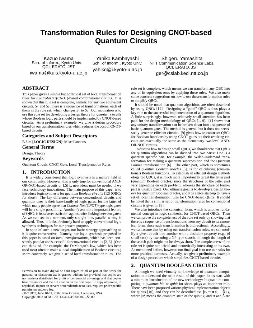
Figure1: A Quantum BooleanCir cuit
complex numberswhich satisfythat (1)�α� 2 � � β � 2 � 1 and(2) if
wemeasure thequantumstate,wegetthestates�0� and
�1� with the
probability�α� 2 and
�β� 2, respectively. This meansthata qubit can
storea superpositionof thestates�0� and
�1� unlikea conventional
bit. In the generalframework of quantumcomputing,we apply aspecificsequenceof unitary operationsto qubits,andgeta desiredsolutionby measuringthefinal quantumstatesof thequbits.Sucha sequenceof unitary operationsis often describedasa quantumBooleancircuit (QBC).
A QBCisaquantumsystemwith N qubits,denotedby�x1 � � x2 ��������
xN � , asillustratedin Fig. 1 wherewe applya specificunitaryop-erationcorrespondingto eachgateoneby one to the qubits
�x1 �
to�xN � from left to right. As an interactionof their qubits, we
canonly useCNOT gateswhosefunctionality will be given later.The left-side
�x1 � � x2 ����� � xn � areusedfor the input, andtheir val-
uesshouldbe restoredfinally. (This restoringis importantwhenthe circuit is usedfor quantumBooleanoraclesas we mentionlater.) The � n � 1� -st qubit
�xn 1 � , calleda work bit, is changed
into�xn 1 � f � x1 � ���� � xn ��� , which is usedto obtain the value of
the Booleanfunction f . Furthermore,a circuit canuseany finitenumberof auxiliary qubitswhich areresetto
�0� initially andalso
restoredto be�0� finally. More formally:
Definition 1. A Control-NOT (CNOT) gateis denotedby � t � C� ,wheret is anintegerandC is a finite setof integers(t �� C).
�xt � is
calleda target bit and�xk � is calleda control bit if k � C.
This kind of gatesis alsocalledn-bit Toffoli gates[11] in re-versiblecomputing. Also theliteraturerefersto � t � C� with only onecontrolbit asa Control-NOT gate,andto � t � C� with two controlbitasControl-Control-NOT gate, andso on, but we simply call bothof themCNOT gatesin this paper. In the figure, we use � for atargetbit and � for a controlbit. For example,the leftmostCNOTgatein Fig. 1 is givenby � n � 1 ��� 1 � 2 � n��� . As its symbolsuggest,� n � 1 ��� 1 � 2 � n��� changesthestateof
�xn 1 � into
�xn 1 � x1 � x2 � xn � ,
where � is theconventionalXOR. (SeeDefinition 3 for details.)Wedenotethesetof N-bit basisvectorsby � 0 � 1� N. Thequantum
stateof N qubits�x1 ������� � xN � is a superposition(a linearcombina-
tion) of those2N basisvectors.However, we oftenassumein thispaperthatthestateis a singlebasisvectorwhendescribingthebe-havior of the system. Generalizationto superposedstatescanbedonesimply by takinga linearcombinationof theresultsfor eachbasisvector.
Definition 2. A quantumBooleancircuit of sizeM over qubits�x1 � � ���� � � xN � is a sequenceof CNOT gates� t1 � C1 ��������� ti � Ci ��������� tM � CM � , where1 � ti � N � Ci � � 1 � ���� � N � . Note
thatunlike the conventionalBooleancircuits we areonly allowedto haveasequenceof CNOT gates.(Wecannotuseso-calledjump-wireswhichpropagatetheresultof onegateto anothergateplacedfaraway. This is animportantdifferencebetweenourcircuit modelandtheconventionalcircuit model.)
Definition 3. The stateof the circuit after the i-th CNOT gate� ti � Ci � is denotedby Si � � xi1 ������������ � xi
N � anddefinedasfollows:(1) S0 � �a1 � �a2 ������� � aN � , where
�a1 � �a2 ������� � aN � � � 0 � 1 � N is an
input state.(2) For 1 � k � N and1 � i � M,
�xi
k ��� � xi � 1k � if k �� ti , and�
xiti ��� � xi � 1
ti � XkCi� whereXk
Ci� 1 � xi1 � �����!� xi j if Ci � � i1 � ���� � i j � .
Here � is the conventionalAND and � is the conventionalXOR
x1x2x3x4x5x6x7
(Circuit A)x1x2x3x4x5x6x7
x1x2x3x4x5x6x7
(Circuit B) (Circuit C)
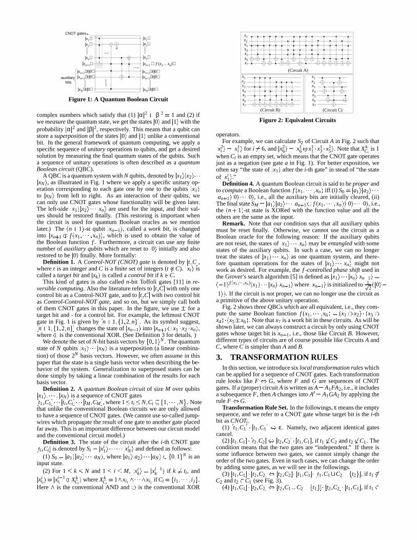
Figure2: Equivalent Cir cuits
operators.For example,we cancalculateS2 of Circuit A in Fig. 2 suchthat�
x2i �"� � x1
i � for i �� 6, and�x2
6 �"� � x16 � x1
1 � x13 � x1
5 � . NotethatXkCi
is 1whenCi is anemptyset,whichmeansthattheCNOT gateoperatesjust asa negation(seegatea in Fig. 1). For betterexposition,weoftensay“the stateof
�x1 � afterthe i-th gate”in steadof “the state
of�xi
1 � .”Definition 4. A quantumBooleancircuit is saidto beproperand
to computeaBooleanfunction f � x1 � ����� � xn � if f (i) S0 � � a1 � � a2 ��������an 1 � � 0������� � 0� , i.e., all theauxiliary bits areinitially cleared,(ii)
Thefinal stateSM � � a1 � � a2 ������� � an 1 � f � x1 � ���� � xn ��� � 0������� � 0� , i.e.,the � n � 1� -st stateis XORedwith the function valueandall theothersarethesameastheinput.
Remark. Note that our conditionsaysthat all auxiliary qubitsmust be resetfinally. Otherwise,we cannotusethe circuit as aBooleanoracle for the following reason: If the auxiliary qubitsarenot reset,thestatesof
�x1 ������� � xn � maybeentangledwith some
statesof the auxiliary qubits. In sucha case,we can no longertreat the statesof
�x1 ������� � xn � asonequantumsystem,and there-
fore quantumoperationsfor the statesof�x1 ����� � xn � might not
work asdesired.For example,the f -controlled phaseshift usedintheGrover’ssearchalgorithm[5] is definedas
�x1 ����� � xn � � xn 1 �#��$ 1� f % x1 & ' ' '(& xn ) � x1 ����� � xn � � xn 1 � where
�xn 1 � is initializedto 1*
2� �0�+$�
1��� . If thecircuit is notproper, we canno longerusethecircuit asa primitive of theaboveunitaryoperation.
Fig.2 showsthreeQBCswhichareall equivalent,i.e.,they com-pute the sameBooleanfunction f � x1 � ���� � x6 �,�-� x1 � x2 �"�.� x3 �x4 ���� x5 � x6 � . Notethatx7 is awork bit in thesecircuits.As will beshown later, wecanalwaysconstructacircuit by only usingCNOTgateswhosetargetbit is xn 1, i.e., thoselike Circuit B. However,differenttypesof circuitsareof coursepossiblelike CircuitsA andC, whereC is simplerthanA andB.
3. TRANSFORMATION RULESIn thissection,weintroducesix local transformationruleswhich
canbeappliedfor asequenceof CNOT gates.Eachtransformationrule looks like F / G, whereF and G are sequencesof CNOTgates.If a(proper)circuitA iswrittenasA � A1FA2, i.e.,it includesa subsequenceF , thenA changesinto A01� A1GA2 by applyingtherule F / G.
Transformation Rule Set. In thefollowings,ε meanstheemptysequence,andwe referto a CNOT gatewhosetargetbit is the i-thbit asCNOTi .
(1) � t1 � C1 �2�3� t1 � C1 �4/ ε. Namely, two adjacentidenticalgatescancel.
(2) � t1 � C1 �3�5� t2 � C2 �2/6� t2 � C2 �3�5� t1 � C1 � , if t1 �� C2 andt2 �� C1. Theconditionmeansthat the two gatesare“independent.” If thereissomeinfluencebetweentwo gates,we cannotsimply changetheorderof thetwo gates.Evenin suchcases,wecanchangetheorderby addingsomegates,aswe will seein thefollowings.
(3) � t1 � C1 �+��� t2 � C2 �7/8� t2 � C2 �!�7� t1 � C1 �!�7� t1 � C1 9 C2 $ � t2 ��� , if t1 ��C2 andt2
�C1 (seeFig. 3).
(4) � t1 � C1 �+��� t2 � C2 �7/8� t2 � C1 9 C2 $ � t1 ���!�:� t2 � C2 �!�:� t1 � C1 � , if t1�
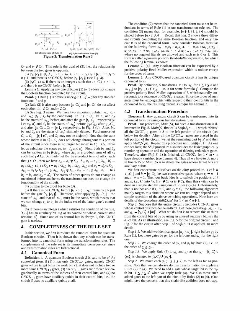
(a) lefthand-side of Rule (3) (b) righthand-side of Rule (3)
⇔|x ⟩t1
|x ⟩t2
[t1, C1]
a1
b1
C’ 1
C2
a2
b1
a2
b2
|x ⟩t1
|x ⟩t2
[t2, C2]
a1
b1
a’ 3
b’ 2
a’ 2
[t1, C1]
b’ 2
C2
C’ 1C’ 1
added
[t1, C1 ∪C2 –{ t2} ][t2, C2]
C2
Figure3: Transformation Rule 3
C2 and t2 �� C1. This rule is the dual of (3), i.e., the relationshipbetweenthetwo gatesis opposite.
(5) � t1 ��� c1 ���+��� t2 � C2 9;� c1 ���</=� t1 ��� c1 ���1��� t2 � C2 9>� t1 ��� , if � t1 ?n � 1� andthereis noCNOTt1 before � t1 ��� c1 ��� (seeFig. 4).
(6) � t � C�"/ ε, if thereis an integer i suchthat i � C � i ? n � 1,andthereis noCNOTi before � t � C� .
Lemma 1. Applying any oneof Rules(1) to (6) doesnotchangetheBooleanfunctioncomputedby thecircuit.
Proof. (1) Rule(1) isobvioussinceg � f � f � g for any Booleanfunctions f andg.
(2) Rule(2) is alsoeasybecause� t1 � C1 � and � t2 � C2 � donotaffecteachotherif t1 �� C2 andt2 �� C1.
(3) SeeFig. 3 again. We have two importantqubits, i.e.,�xt1 �
and�xt2 � (t1 �� t2 by the condition). In Fig. 3 (a), let a1 and a2
bethestatesof�xt1 � beforeandafter thegate � t1 � C1 � , respectively.
Let a1, a02 anda03 bethestatesof�xt1 � before � t2 � C2 � , after � t1 � C1 �
andafter � t1 � C1 9 C2 $ � t2 ��� , respectively, in Fig. 3 (b). Also, b1,b2 andb02 arethestatesof
�xt2 � similarly defined.Furthermorelet
C01 � C1 $ � t2 � (C01 andC2 maynotbedisjoint). Notethatthestatewhoseindex is in C 01 9 C2 doesnot changethroughoutthis portionof the circuit sincethereis no target bit index in C01 9 C2. Nowlet us calculatethe statesa2, b2, a03 andb02. First, both b2 andb02canbe written asb1 � XC2, whereXC2 is a productterm of all x jsuchthat j � C2. Similarly, let XC @1 bea producttermof all x j suchthat j � C01, thenwe have a2 � a1 � XC @1 � b1, a02 � a1 � XC@1 � b02 �a1 � XC @1 �A� b1 � XC2 �"� a1 � XC @1 � b1 � XC2 � XC @1 anda03 � a02 � XC2 �XC@1 � a1 � XC@1 � b1 � XC2 � XC @1 � XC2 � XC@1 � a1 � XC@1 � b1. Thusb2 � b02 anda2 � a03. Thestatesof otherqubitsdo not changeasmentionedbeforeandhencethetransformationdoesnotchangethefunctionalityof thecircuit.
(4) Similar to theproof for Rule(3).(5) If thereis noCNOTt1 before � t1 ��� c1 ��� , � xt1 � remains
�0� just
beforethe gate � t1 ��� c1 ��� . Therefore,after applying � t1 ��� c1 ��� , thestateof
�xt1 � andthatof
�xc1 � mustbe thesame,which meansthat
we canchanget1 to c1 in the index setof the latter gate’s controlbits.
(6) If thereis anintegeri whichsatisfiestheconditionof therule,� t � C� hasanauxiliary bit�xi � asits controlbit whosecurrentstate
remains�0� . Sinceoneof its control bits is always0, this CNOT
gateis useless. B4. COMPLETENESS OF THE RULE SET
In thissection,wefirst introducethecanonicalform for quantumBooleancircuits. Then it is shown that any circuit can be trans-formedinto its canonicalform usingthetransformationrules.Thecompletenessof the rule set is its immediateconsequence,sinceour transformationrulesarebidirectional.
4.1 Canonical FormDefinition 4. A quantumBooleancircuit S is saidto be of the
canonicalform, if (1) it hasonly CNOTn 1 gates,namelyCNOTgateswhosetargetbit is thework bit, (2) it doesnot includetwo ormoresameCNOTn 1 gates,(3)CNOTn 1 gatesareorderedlexico-graphicallyin termsof the indicesof their controlbits, and(4) noCNOTn 1 gateshave auxiliary qubitsin their controlbits, i.e., thecircuit Susesnoauxiliary qubitsat all.
Thecondition(2) meansthatthecanonicalform mustnot bere-dundantin termsof Rule (1) in our transformationrule set. Thecondition(3) meansthat, for example, � n � 1 ��� 1 � 2 � 3��� shouldbeplacedbefore � n �C� 2 � 3 � 4 ��� . Recall that Fig. 2 shows threediffer-ent circuits computingthe sameBooleanfunction, andonly Cir-cuit B is of the canonicalform. Now considerBooleanformulasof the following form: a0 � a1x1 � a2x2 � ����� � anxn � a1 & 2x1x2 �a1 & 3x1x3 � ���� � an � 1 & nxn � 1xn � ���������� � a1 & 2 & ' ' ' n � 1 & nx1x2 ���� xn � 1xn �whereno negatedliterals areallowed andeachai is 0 or 1. Thisform is calledapositivepolarity Reed-Mullerexpression, for whichthefollowing lemmais known:
Lemma 2. [4]. Any Booleanfunction canbe expressedby apositive polarity Reed-Mullerexpressionwhich is uniqueexceptfor theorderof terms.
Lemma 3. Any CNOT-basedquantumcircuit S hasits uniquecanonicalform.
Proof. By definition,S transforms�xi � to
�xi � for 1 � i � n and�
xn 1 � to�xn 1 � f � x1 � ����� � xn ��� for someformula f . Computethe
positivepolarityReed-Mullerexpressionof f , whichnaturallycor-respondsto a sequenceof CNOTn 1 gates.Sincetheorderof suchgatesmustbelexicographicwith respectto their controlbits in thecanonicalform, theresultingcircuit is uniqueby Lemma2. B4.2 Transformation Procedure
Theorem 1. Any quantumcircuit Scanbetransformedinto itscanonicalform by usingour transformationrules.
Proof. Our procedure,Main � S� , for sucha transformationis il-lustratedin Fig. 8. Main � S� first callsShift� S� n � 1� which“shifts”all theCNOTn 1 gatesin S to the left portion of the circuit (seebelow for details). After all theCNOTn 1 gatesareplacedin theleft portionof thecircuit, we let theremainingpartbeS0 andthenapplyShift� S0 � n� . Repeatthis procedureuntil Shift� S0 � 1� . As onecanseelater, theShiftprocedurealsoincludesthelexicographicallyreorderingoperationandtheoperationof deletingredundantgates.Therefore,after Shift� S0 � 1� is finished,all CNOTm for 1 � m � nhavealreadyvanished(seeLemma4). Thusall wehaveto domorein line 9-15of Main � S� is to deletethegateswhosetargetbits areauxiliaryqubits.
We first concentrateourselveson the Shift procedure.Let k �� t1 � C1 � andh �D� t2 � C2 � betwo consecutive gates,wheret2 � n � 1andt1 �� n � 1. Thenour basicideais to switch thepositionsof kandh, i.e.,kh into hk. If t1 �� C2 or t2 �� C1, thenthis switchcanbedonein a singlestepby usingoneof Rules(2)-(4). Unfortunately,that is not possibleif t1
� C2 andt2� C1; the following algorithm
mainly targetsthis situationwherewe canno longerdependon asimplerepetitionof theabove switchingoperations.Now herearedetailsof theprocedureShift� S� m� for 1 � m � n � 1:
Step1. Supposethat theentirecircuit S includesk CNOT gateswhosecontrolbitsincludethem-thbit. Let thesegatesbeg1 � g2 � ����� gk,andg j �E� t j � C0j 9>� m��� . Whatwe do first is to remove this m-th bitfrom thecontrolbitsof g j by usinganunusedauxiliarybit, saythea j -th bit. As anillustration,seeFig. 5 for theoriginal circuit SandFig. 7 for thecircuit afterStep1 of Shift� S� 3� is applied. In moredetail:
Step1.1.Weaddtwo identicalgates� a j ��� m��� , right beforeg j byRule(1). Let thesegatesbegl j
for theleft oneandgr j for therightone.
Step1.2. We changetheorderof gr j andg j by Rule (2), i.e., totheorderof gl j
g jgr j .Step1.3. We applyRule (5) to gl j
andg j so thatg j �F� t j � C0j 9� m��� is changedto � t j � C 0j 9G� a j ��� .Step2. We move eachgl j � 1 � j � k� to the left asfar aspos-
sible. Notethatwe canalwaysdo this transformationby applyingRules(2) to (4). We needto adda gatewhosetargetbit is thea j -th bit � 1 � j � k � whenwe apply Rule (4). We alsomove suchaddedgatesto the left partof thecircuit by Rules(2) to (4). (Onemight have theconcernthat this chain-like additiondoesnot stop.
⇔
auxiliary bits
|0⟩
Figure4: Transformation Rule 5
H I J KH I L K M N M O M PH I Q K
Figure5: Initial Cir cuit
R S T UR S V UR S W U
Figure6: The Final Result
X Y X Z X [X X\ ] X X X X^ _ [ `^ _ Z `^ _ a `b^ _ a `c^ _ a `de ^ f `e ^ f `e ^ f `
^ _ Y `
g ] \ h g h \ i g iFigure7: The Cir cuit after Step1
1 Main j Sk2 l3 S’ = S4 for (i = n m 1 to 1) l5 Shiftj Sn o i k6 Ci p SL /* theleft partof theresultof Shiftj Sn o i k which consist7 of onlyCNOTi gates*/8 Sn p SR /* theremainingpartof theresultof Shiftj Snqo i k */9 r10 while (gatesg thathave auxiliaryqubitsin its controlbitsexist) l11 Let g betheleft mostoneof suchgates.12 Move g to thenext right positionof CNOTns 1 by applyingone13 of Rules(2) and(4) asmany timesaspossible.14 Deleteg by applyingRule(6).15 r16 Reorderthegateswhosetargetbits areauxiliaryqubitslexicographically17 by applyingRule(2) asmany timesaspossible.18 Deleteredundantpairof gatesby applyingRule(1) asmany timesaspossible.19 r
Figure8: Main t Suv w w x w v y z y x { |
} ~ � �} ~ � � � � � � � �
} ~ � �} ~ � ��} ~ � ��} ~ � ��� } � �� } � �� } � � � � � � � �� � � � � �� � � � � �
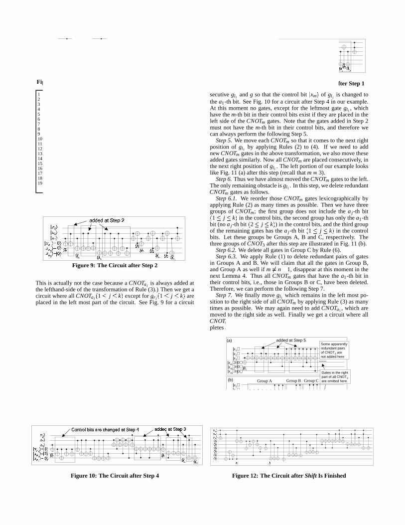
Figure9: The Cir cuit after Step2
This is actuallynot thecasebecauseaCNOTaj is alwaysaddedatthelefthand-sideof thetransformationof Rule(3).) Thenwe getacircuit whereall CNOTaj t 1 � j � ku exceptfor gr j t 1 � j � ku areplacedin the left mostpart of the circuit. SeeFig. 9 for a circuitafterStep2 in our example.
Step3. We thenmove eachgr j t 1 � j � k u to theoppositedirec-tion, i.e., to the right asfar aspossible.Again we canalwaysdothis by applyingRules(2) to (4) andexactly thesameasbeforeasfor the addedgateswhosetargetbits area j -th t 1 � j � ku . Thuswe get the circuit whereall CNOTaj t 1 � j � ku areplacedin theleft mostpartor in theright mostpartof thecircuit.
Step4. Without loss of generalitywe can assumethat gl1 isplacedat the left-endpositionof the circuit after Step2. As onecan seelater, we can overcomeseveral difficulties we encounterwhenmoving CNOTm gatesto the left, by giving a specialrole tothis gategl1 . Now, for eachgateg which hasthe m-th bit in itscontrolbitsandplacedin thelefthand-sideof theCNOTm gates,weapplythefollowing transformations:First we move g to theleft sothat it comesto thenext right positionof gl1 by usingRule (2) or(3) asmany timesaspossible.ThenweapplyRule(5) to now con-
� � � �� � � �� � � � � � � � � � � � � � � �� � � � � ¡ ¢ £ � ¤ � � ¥ ¦ � � § � � � � � � � � ¨
� � © �ª� � © �«� � © �¬ � ® � � ® � � ® � ¯ ° ± ¯ ² ± ¯ ² ³ ¯ ² ´
Figure10: The Cir cuit after Step4
secutive gl1 andg so that the control bit�xm � of gl j
is changedtothea1-th bit. SeeFig. 10 for a circuit afterStep4 in our example.At this momentno gates,except for the leftmostgategl1, whichhave them-th bit in their controlbits exist if they areplacedin theleft sideof theCNOTm gates.Note that thegatesaddedin Step2mustnot have the m-th bit in their control bits, andthereforewecanalwaysperformthefollowing Step5.
Step5. We move eachCNOTm sothat it comesto thenext rightposition of gl1 by applying Rules(2) to (4). If we needto addnew CNOTm gatesin theabovetransformation,wealsomovetheseaddedgatessimilarly. Now all CNOTm areplacedconsecutively, inthenext right positionof gl1 . Theleft portionof ourexamplelookslike Fig. 11 (a)afterthisstep(recall thatm � 3).
Step6. ThuswehavealmostmovedtheCNOTm gatesto theleft.Theonly remainingobstacleis gl1 . In thisstep,wedeleteredundantCNOTm gatesasfollows.
Step6.1. We reorderthoseCNOTm gateslexicographicallybyapplyingRule (2) asmany timesaspossible.Thenwe have threegroupsof CNOTm; the first group doesnot include the a j -th bit� 1 � j � k� in thecontrolbits, thesecondgrouphasonly thea1-thbit (noa j -th bit � 2 � j � k � ) in thecontrolbits,andthethird groupof theremaininggateshasthea j -th bit � 1 � j � k� in thecontrolbits. Let thesegroupsbe GroupsA, B andC, respectively. Thethreegroupsof CNOT3 afterthisstepareillustratedin Fig. 11 (b).
Step6.2.We deleteall gatesin GroupC by Rule(6).Step6.3. We apply Rule (1) to deleteredundantpairsof gates
in GroupsA andB. We will claim that all the gatesin GroupB,andGroupA aswell if m �� n � 1, disappearat this momentin thenext Lemma4. Thusall CNOTm gatesthat have the a1-th bit intheir control bits, i.e., thosein GroupsB or C, have beendeleted.Therefore,we canperformthefollowing Step7.
Step7. We finally move gl1 which remainsin the left mostpo-sition to theright sideof all CNOTm by applyingRule(3) asmanytimesaspossible.We may againneedto addCNOTa1 , which aremovedto theright sideaswell. Finally we geta circuit whereallCNOTm areplacedin the left mostpart of the circuit. That com-pletesShift� S� m� .
added at Step 5
|x3⟩
|xa ⟩2
|xa ⟩1
|xa ⟩3
=|0⟩=|0⟩=|0⟩
(a)
|x2⟩
Group A(b)
Gates in the right part of all CNOT3are omitted here.
|x1⟩Some apparently redundant pairs of CNOT3 are not added here
|x3⟩|x2⟩
|xa ⟩2
|xa ⟩1
|xa ⟩3
=|0⟩=|0⟩=|0⟩
|x1⟩Group B Group C
µl1
µl1
Figure11: The Cir cuit in Step6
¶ ·
¸ ¹ º »¸ ¹ ¼ »¸ ½ »¸ ½ »¸ ½ »¸ ½ »¸ ½ »
¸ ¹ ¾ »
¸ ½ »Figure12: The Cir cuit after Shift Is Finished
Lemma 4. All the gatesin GroupB mustdisappearafter Step6.3of¿ Shift� S� m� if thecircuit S is proper. All thegatesin GroupAmustalsodisappearwhenm �� n � 1.
Proof. Below we considerthestateof�xm � . Recallthatwe have
only gl1 in theleft partof GroupA. Therefore,beforeGroupA thestatesof
�x1 � to
�xn 1 � remainunchanged,i.e.,beingequalto their
initial states,andonly�xa1 � haschangedto beequalto
�xm � .
Supposethat somegatesin GroupsA or B have remainedafterStep6.3,andlet the i-th suchgatein GroupA be �m� CAi � , andthei-th gatein GroupB be �m� CBi � . Furthermore,let XCAi
be a prod-uct term of all x j suchthat j � CAi , and XCBi
be a producttermfor CBi . Then the value of the stateof
�xm � after Group A can
bewritten asxm � XCA1 � XCA2 � �����1� xm � � XCA1 � XCA2 � ������À�xm � fA becauseof associative laws for the XOR operator. Animportantpoint here is that XCA1 � XCA2 � ����� are all different sinceStep6.3 includesthe simplificationprocedure(by Rule (1)) afterreorderingthe gatesinto the lexicographicalorder. This meansthat fA is a positive polarity Reed-Mullerform. Also notethat fAdoesnot have theliteral xm sinceeachCAi doesnot includem. Wethencancalculatethe valueof the stateof
�xm � after GroupB as
xm � fA � XCB1 � XCB2 � ����� . Recall that all the gatesin GroupBhave the a1-th bit as their control bits, therefore,all XCBi
in theformula contain the literal xa1 which is equal to xm becauseofthe leftmostgategl1. Accordingly, we canrewrite the formula as� xm � fA � xm f 0B � , where f 0B doesnot have the literal xm and is apositive polarity Reed-Mullerform again.(TheXOR hasdistribu-tive laws, for example,xyz� x � x � yz � 1� .)
SincetherearenoCNOTm afterGroupB (recall thatGroupC’sgateshavealreadydisappeared)andthecircuit is proper, we have
�xm � fA � xm f 0B �#�
Á �xm � if 1 � m � n,�xm � f � if m � n � 1,
where f hasonly literalsx1 throughxn. Now we canconcludethatfA � f 0B � 0 if 1 � m � n, and f 0B � 0 if m � n � 1 for thefollowingreason:The above formulascanbe expandedwith respectto xm,i.e., xm � fA � xm f 0B �� fA f 0B � fA f 0B � xm � fAxm, and xm � f �f xm � f xm. Onecanseethatthesetwo functionsareequivalentifff � fA f 0B � fA f 0B and f � fA, which implies f 0B � 0. Onecanalso
seethat � fA f 0B � fA f 0B � xm � fAxm � xm implies fA � f 0B � 0. Alsonote that if g � X1 � X2 � ���� is a positive polarity Reed-Mullerform, theng � 0 iff X1 � X2 �D���� 0. Therefore,no producttermsareincludedin fA or f 0B, i.e., thereshouldbeno gatesin GroupB,andneitherin GroupA whenm �� n � 1. B
After wesuccessfullygetacircuit whereall CNOTn 1 areplacedin theleft mostpartof thecircuit by Shift� S� n � 1� , Main thencallsShift� S0 � n� , by which all CNOTn gatesareshiftedto theleft. Theyareplacednext to CNOTn 1 gatesalreadyshifted. Thenwe candeleteall CNOTn by Lemma4. Thiscontinuesuntil Shift� S0 � 1� . Inour example,aftercallingShift� S0 � 1� , we geta circuit in Fig. 12.
After the8th line in Fig. 8, we have CNOTn 1 gateswhich arealreadyof thecanonicalform at theleft partof thecircuit andthenCNOTi gates � i à n � 2� after them. Now we executethe secondhalf of Main, wherewe deleteall theCNOTi � i à n � 2� gates,i.e.,thosewhosetargetbits areauxiliary ones,andfinally thereremainonly CNOTn 1 gatesin thecircuit.
TheCNOTi � i à n � 2� gatesaredivided into two groups. Thefirst group,denotedby A, hascontrolbits in auxiliary bits andthesecondgroup, B, doesnot. We first move group A gatesto theleft until the next positionsto CNOTn 1 gates.This canbe doneby switchinggroupA gateswith groupB gates,which is alwayspossibleby usingRules(2)-(4). (Switchingtwo gatesbothin groupA, like gatesa andb in Fig. 12, is not soeasy.) ThenthegroupAgatescanbedeletedoneby onefrom theleftmostoneby Rule(6).Thenwe haveonly groupB gates.Recallthatwhenwe introduceda CNOTi � i à n � 2� gates,we always introducedanotherCNOTi
which cancelsthe valueof�xi � . Thereforethe final valuesof the
auxiliary qubits are all 0. Thereforewe can deletethe group Bgatesby reorderingand applying Rule (1). (Otherwise,we canimply a contradictionjust aswe did in theproof of Lemma4.) Inour example,we successfullygetto a circuit in Fig. 6 which is thecanonicalform for theinitial circuit. B4.3 Completenessof the Rule Set
Now ourmainresultis almostimmediate:Theorem 2. Let S1 andS2 beany equivalentquantumBoolean
circuits.Thenthereexistsasequenceof transformationrules,eachin therule setgivenin Section3, which transformsS1 to S2.
Proof. SinceS1 andS2 areequivalent,their canonicalformsarethesameby Lemma3. Let thiscanonicalform beS. Wecantrans-form S1 into Sby Theorem1. Let this sequenceof transformationrulesber1. We canalsotransformS2 into Sby sequencer2. Sinceall of our transformationrulesarebidirectional,we canget a se-quencer 02 of rulesthat transformsS to S2 simply by reversingr2.Now thesequencer1 followedby r 02 transformsS1 into S2. B5. CONSTRUCTION OF EFFICIENT CIR-
CUITSIn this section,we proposeanexampleof circuit designproce-
durebasedon our transformationrules. The designflow consistsof thefollowing threesteps:
Step1. We make an arbitrary initial CNOT-basedcircuit froma givenformula(dependingon theproblemfor thequantumalgo-rithm).
Step2. We transformthe initial circuit to its canonicalform byourprocedureMain � S� in Section4.
Step3. A new transformationrule is givenin Section5.2,whichcanberealizedby composingour transformationrulesandguaran-teesa reductionif thecostof thecircuit. We just applythis rule asmany timesaspossible.
For Step1, it shouldbenotedthatif wecanuseauxiliaryqubits,we can simulateany type of formula by a CNOT-basedcircuitwhosesizeis almostthesameasthegivenformula.Here,weshowhow to simulateCNF formulasby CNOT-basedcircuits in thefol-lowing section.
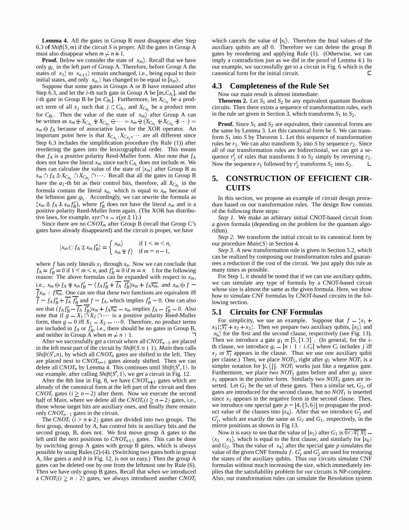
5.1 Cir cuits for CNF FormulasFor simplicity, we use an example. Supposethat f �� x1 �
x3 �5� x1 � x2 � x3 � . Thenwe preparetwo auxiliary qubits,�x5 � and�
x6 � for the first andthesecondclause,respectively (seeFig. 13).Thenwe introducea gateg1 �� 5 �C� 1 � 3��� . (In general,for the i-th clause,we introducegi �F� n � 1 � i � Ci � whereCi includes j if fx j or x j appearsin the clause. Thus we useone auxiliary qubitperclause.)Then,we placeNOT5, right afterg1 whereNOTi is asimplernotationfor � i ��� ��� . NOTi works just like a negationgate.Furthermore,we placetwo NOT1 gatesbeforeandafter g1 sincex1 appearsin thepositive form. Similarly two NOT3 gatesarein-serted.Let G1 bethesetof thesegates.Thena similar set,G2, ofgatesareintroducedfor thesecondclause,but no NOT1 is insertedsincex1 appearsin the negative form in thesecondclause.Then,we introduceonespecialgatep �� 4 �C� 5 � 6 ��� to propagatetheprod-uct valueof theclausesinto
�x4 � . After thatwe introduceG02 and
G01, which areexactly thesameasG2 andG1, respectively, in themirror positionsasshown in Fig 13.
Now it is easyto seethatthevalueof�x5 � afterG1 is 0 � x1 x3 �� x1 � x3 � , which is equalto thefirst clause,andsimilarly for
�x6 �
andG2. Thusthevalueof�x4 � afterthespecialgatep simulatesthe
valueof thegivenCNFformula f . G01 andG02 areusedfor restoringthe statesof theauxiliary qubits. Thusour circuits simulateCNFformulaswithoutmuchincreasingthesize,which immediatelyim-pliesthatthesatisfiabilityproblemfor ourcircuitsis NP-complete.Also, our transformationrulescansimulatetheResolutionsystem
Ç È É Ç Ê É Ç Ë É Ç Ì É Ç Í É
Î ÏÎ ÐÎ ÑÎ ÒÎ ÓÎ ÔÎ Õ È Ê Ë Ì Í Ö ×
Î ÏÎ ÐÎ ÑÎ ÒÎ ÓÎ ÔÎ Õ ×
Ø È Ù Ì Ú Ø Ê Ù Í Ú Ø Ë Ù Ö Ú
Û Ü Ý Þ ßÈ Ê Ë
Î ÏÎ ÐÎ ÑÎ ÒÎ ÓÎ ÔÎ Õ ×È Ê Ë à á ß
Î ÏÎ ÐÎ ÑÎ ÒÎ ÓÎ ÔÎ Õ È Ê Ëâ ã ä ß
Î ÏÎ ÐÎ ÑÎ ÒÎ ÓÎ ÔÎ Õ
Ø â Ù ã Ú
È Êã
Ø Ê Ù Ë Ú Ø ä Ù ß Ú
äFigure15: A Minimization Procedure
å æ ç è é è å ê ëì è í î ï ð ñ ò ó ï ô òï ð õ ò ó ï ô òï ð ö òï ð ÷ òï ð ø òï ð ù ò
ï ð ö òï ð ÷ òï ð ù òï ð ñ ò ó ï ô òï ð õ ò ó ï ô òú ÷ ûú ö ú ü ö ú ü ÷ï ð ø ý þ ð ÷ ÿ ð ù � þ ð ÷ ÿ ð ö ÿ ð ù � ò
þ ð ÷ ÿ ð ù �
� ÷
þ ð ÷ ÿ ð ö ÿ ð ù �
� öFigure13: A Cir cuit for � x1 � x3 � � x1 � x2 � x3 �
��� �
�
� �
��� �
� �
� �
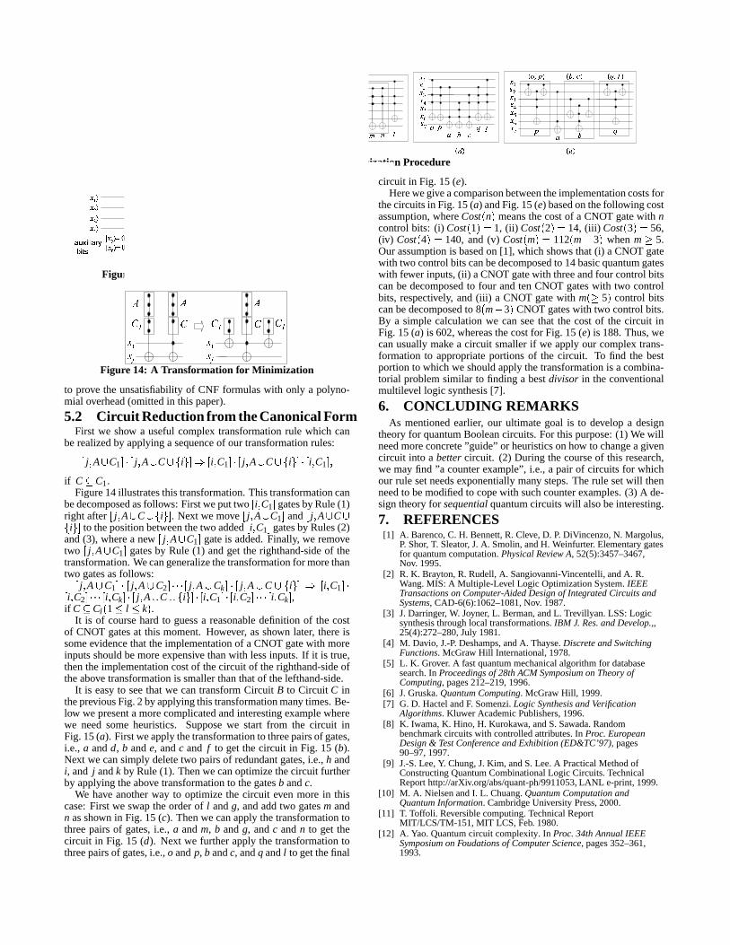
Figure14: A Transformation for Minimization
to prove the unsatisfiabilityof CNF formulaswith only a polyno-mial overhead(omittedin thispaper).
5.2 Cir cuit Reductionfr omtheCanonicalFormFirst we show a usefulcomplex transformationrule which can
berealizedby applyinga sequenceof our transformationrules:�j � A C1 ��� � j � A C �� i � ��� �
i � C1 ��� � j � A C �� i � ��� � i � C1 � �if C � C1.
Figure14illustratesthistransformation.Thistransformationcanbedecomposedasfollows: Firstweputtwo
�i � C1 � gatesbyRule(1)
right after�j � A C �� i � � . Next we move
�j � A C1 � and
�j � A C � i � � to thepositionbetweenthetwo added
�i � C1 � gatesby Rules(2)
and(3), wherea new�j � A C1 � gateis added.Finally, we remove
two�j � A C1 � gatesby Rule (1) andget therighthand-sideof the
transformation.Wecangeneralizethetransformationfor morethantwo gatesasfollows:�
j � A C1 ��� � j � A C2 ������� � j � A Ck ��� � j � A C �� i � ��� �i � C1 ����
i � C2 ������� � i � Ck ��� � j � A C �� i � ��� � i � C1 ��� � i � C2 ������� � i � Ck � ,if C � Cl � 1 � l � k� .
It is of coursehardto guessa reasonabledefinition of the costof CNOT gatesat this moment.However, asshown later, thereissomeevidencethattheimplementationof a CNOT gatewith moreinputsshouldbemoreexpensive thanwith lessinputs.If it is true,thentheimplementationcostof thecircuit of therighthand-sideoftheabove transformationis smallerthanthatof thelefthand-side.
It is easyto seethatwe cantransformCircuit B to Circuit C inthepreviousFig.2 byapplyingthistransformationmany times.Be-low we presenta morecomplicatedandinterestingexamplewherewe needsomeheuristics. Supposewe start from the circuit inFig.15(a). Firstweapplythetransformationto threepairsof gates,i.e., a andd, b ande, andc and f to get thecircuit in Fig. 15 (b).Next we cansimply deletetwo pairsof redundantgates,i.e.,h andi, and j andk by Rule(1). Thenwecanoptimizethecircuit furtherby applyingtheabove transformationto thegatesb andc.
We have anotherway to optimizethe circuit even more in thiscase:First we swaptheorderof l andg, andaddtwo gatesm andn asshown in Fig. 15 (c). Thenwe canapplythetransformationtothreepairsof gates,i.e., a andm, b andg, andc andn to get thecircuit in Fig. 15 (d). Next we furtherapply the transformationtothreepairsof gates,i.e.,o andp, b andc, andq andl to getthefinal
circuit in Fig. 15 (e).Herewegiveacomparisonbetweentheimplementationcostsfor
thecircuitsin Fig.15(a) andFig.15(e) basedonthefollowing costassumption,whereCost � n� meansthecostof a CNOT gatewith ncontrolbits: (i) Cost � 1� � 1, (ii) Cost � 2�!� 14, (iii) Cost � 3�!� 56,(iv) Cost � 4�"� 140, and(v) Cost � m�#� 112� m $ 3� whenm % 5.Our assumptionis basedon [1], which shows that(i) a CNOT gatewith two controlbitscanbedecomposedto 14basicquantumgateswith fewer inputs,(ii) aCNOT gatewith threeandfour controlbitscanbedecomposedto four andtenCNOT gateswith two controlbits, respectively, and(iii) a CNOT gatewith m�&% 5� control bitscanbedecomposedto 8 � m $ 3� CNOT gateswith two controlbits.By a simplecalculationwe canseethat the costof the circuit inFig. 15(a) is 602,whereasthecostfor Fig. 15 (e) is 188.Thus,wecanusuallymake a circuit smallerif we applyour complex trans-formation to appropriateportionsof the circuit. To find the bestportionto which we shouldapplythetransformationis acombina-torial problemsimilar to finding a bestdivisor in theconventionalmultilevel logic synthesis[7].
6. CONCLUDING REMARKSAs mentionedearlier, our ultimategoal is to develop a design
theoryfor quantumBooleancircuits.For this purpose:(1) Wewillneedmoreconcrete”guide” or heuristicsonhow to changeagivencircuit into a bettercircuit. (2) During thecourseof this research,we mayfind ”a counterexample”, i.e., a pair of circuits for whichour rule setneedsexponentiallymany steps.Therule setwill thenneedto bemodifiedto copewith suchcounterexamples.(3) A de-signtheoryfor sequentialquantumcircuitswill alsobeinteresting.
7. REFERENCES[1] A. Barenco,C. H. Bennett,R. Cleve,D. P. DiVincenzo,N. Margolus,
P. Shor, T. Sleator, J.A. Smolin,andH. Weinfurter. Elementarygatesfor quantumcomputation.PhysicalReview A, 52(5):3457–3467,Nov. 1995.
[2] R. K. Brayton,R. Rudell,A. Sangiovanni-Vincentelli , andA. R.Wang.MIS: A Multiple-Level Logic OptimizationSystem.IEEETransactionsonComputer-AidedDesignof IntegratedCircuitsandSystems, CAD-6(6):1062–1081,Nov. 1987.
[3] J.Darringer, W. Joyner, L. Berman,andL. Trevillyan. LSS:Logicsynthesisthroughlocal transformations.IBM J. Res.andDevelop.,,25(4):272–280,July1981.
[4] M. Davio, J.-P. Deshamps,andA. Thayse.DiscreteandSwitchingFunctions. McGraw Hill International,1978.
[5] L. K. Grover. A fastquantummechanicalalgorithmfor databasesearch.In Proceedingsof 28thACM SymposiumonTheoryofComputing, pages212–219,1996.
[6] J.Gruska.QuantumComputing. McGraw Hill, 1999.[7] G. D. HactelandF. Somenzi.Logic SynthesisandVerification
Algorithms. Kluwer AcademicPublishers,1996.[8] K. Iwama,K. Hino, H. Kurokawa,andS.Sawada.Random
benchmarkcircuitswith controlledattributes.In Proc.EuropeanDesign& TestConferenceandExhibition(ED&TC’97), pages90–97,1997.
[9] J.-S.Lee,Y. Chung,J.Kim, andS.Lee.A PracticalMethodofConstructingQuantumCombinationalLogic Circuits.TechnicalReporthttp://arXiv.org/abs/quant-ph/9911053,LANL e-print,1999.
[10] M. A. NielsenandI. L. Chuang.QuantumComputationandQuantumInformation. CambridgeUniversityPress,2000.
[11] T. Toffoli. Reversiblecomputing.TechnicalReportMIT/LCS/TM-151,MIT LCS,Feb. 1980.
[12] A. Yao.Quantumcircuit complexity. In Proc.34thAnnualIEEESymposiumonFoudationsof ComputerScience, pages352–361,1993.