transducer of network parameters p43 type · parameters are accessible ... messa es after sw tch n...
TRANSCRIPT
�
TRANSDUCER OF NETWORK PARAMETERSP43 TYPE
USER’S MANUAL

�

�
Contents
1. Application...................................................................... 5
2. TransducerSet................................................................. 6
3. BasicRequirementsandOperationalSafety.............................. 6
4. Installation...................................................................... 7
5. Service.......................................................................... 12
6. Archive-PowerProfile....................................................... 30
7. ErrorCodes..................................................................... 30
8. SerialInterfaces............................................................... 31
9. ExamplesofP43TransducerProgramming............................... 40
10. TechnicalData................................................................. 43
11. ExecutionCodes............................................................... 46
12. MaintenanceandGuarantee................................................ 47

�

�
1. �����C����������C�����
TheP43transducerisaprogrammabledigitalinstrumentdestinedforthemeasurementandparameterconversionof3or4-wirethree-phasepowernetworks,inbalancedandunbalancedsystems.Itensures themeasurementandconversionofmeasuredvalues intostandardanalogcurrentsignals.Tworelayoutputssignaltheoverflowofselectedquantities,andthepulseoutputcanbeusedforthecon-sumptionmonitoringofthe3-phaseactiveenergy.Quantitiesmeasuredandcalculatedbythetransducer:l phase voltagesphasevoltages......................................................U1,U2,U3
l phase.to-phase voltagesphase.to-phasevoltages.....................................U12,U23,U31
l 3-phase mean voltage3-phasemeanvoltage..........................................Ul phase-to-phase mean voltagephase-to-phasemeanvoltage.............................UPPl three-phase mean currentthree-phasemeancurrent.....................................Il phase currentsphasecurrents.....................................................I1,I2,I3
l phase active powersphaseactivepowers.............................................P1,P2,P3
l phase reactive powersphasereactivepowers..........................................Q1,Q2,Q3
l phase apparent powersphaseapparentpowers........................................S1,S2,S3
l phaseactivepowerfactors...................................Pf1,Pf2,Pf3
l reactive/activeratioofpowerfactors....................tgj1,tgj2,tgj3
l three-phasemeanpowerfactors..........................Pf,tgjl three-phaseactive,reactiveandapparentpowers...P,Q,Sl activemeanpower(e.g.15min.)...........................Pav
l three-phaseactiveandreactiveenergy...............Ept,Eqt,l frequencyfrequency.............................................................f
Thetransducerpossessesanarchive,inwhich1000lastmeanpowervaluessuitablysynchronizedwiththeclock(15,30or60minutes)arestored.Maximalandminimalvaluesaremeasuredforallquantities.Additional-ly, there is thepossibility toaccommodate the transducer toexternalmeasuringtransducers.Thetransducerhasadetectionandsignalingof incorrectphasesequence.Theactualizationtimeofallaccessible
�
2. �r��sduCer se�
ThesetoftheP43transduceriscomposedof:-P43 transducer 1 pcP43transducer 1 pc 1pc-user�s manual 1 pcuser�smanual 1 pc 1pc-guarantee card 1 pcguaranteecard 1 pc 1pc-��� disc 1 pc���disc 1 pc 1pc
When unpacking the transducer, please check whether the type and execution code on the data plate correspond to the order.
quantitiesdoesnotexceed1second.AllquantitiesandconfigurationparametersareaccessiblethroughtheRS-485interfaceandtheUSBinterface.Transducer output signals are galvanically isolated from the inputsignaland thesupply.Outside the transducer, therearesocket-plug
3. B�s�C requ�reme��s ��d ��er������� s�fe�y
Inthesafetyservicescope,thetransducermeetstorequirementsoftheEN61010-1standard.Observations Concerning the Operational Safety��l Alloperationsconcerningtransport,installation,and commissioningaswellasmaintenance,mustbecarriedoutby qualified,skilledpersonnel,andnationalregulationsforthe preventionofaccidentsmustbeobserved.l Beforeswitchingthetransduceron,onemustcheckthe correctnessofconnectionstothenetwork.l Beforeremovingthetransducerhousing,onemustswitchthe supplyoffanddisconnectmeasuringcircuits.

�
4. ��s�����������s���������
4.1. f�tt�n�f�tt�n�TheP43transducerisadaptedtobemountedona35mmrailacc.toEN60715.Theoveralldrawingandthefittingwayarepresentedonthefig.1.
Fig.� Overall Dimensions and Transducer Fitting Way.
l Theremovalofthetransducerhousingduringtheguarantee contractperiodmaycauseitscancellation.l TheP43transducerisdestinedtobeinstalledandusedin industrialelectromagneticenvironmentconditions.l Onemustrememberthatinthebuildinginstallation,aswitchora circuit-breakershouldbeinstalled.Thisswitchshouldbelocated nearthedevice,easyaccessiblebytheoperator,andsuitably marked.
�
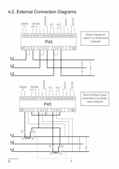
4.2. external Connect�on d�a�rams
Semi-indirect mea-surement in a three-
wire network
Direct measure-ment in a three-wire
network

�
Ind
irect
mea
sure
men
t with
the
use
of
� cu
rren
t tra
nsfo
rmer
s an
d �
or
� vo
ltag
e tr
ansf
orm
ers
in a
thre
e-w
ire n
etw
ork.
Fig
. �.
Con
nect
ion
Dia
gra
ms
of th
e Tr
ansd
ucer
in a
Thr
ee-w
ire N
etw
ork
Cau
tio
n:
In in
du
stri
al e
nvi
ron
men
t w
ith
hig
h e
lect
rom
agn
etic
n
ois
es, i
t is
rec
om
men
ded
to
ear
th t
he
term
inal
11.

�0
Semi-indirect measurementin a four-wire
network
Direct measurementin a four-wire network
��
Ind
irect
mea
sure
men
t with
the
use
of �
cur
rent
tr
ansf
orm
ers
and
� o
r �
volta
ge
tran
sfor
mer
s in
a
four
-wire
net
wor
k
Fig.
3.
Con
nect
ion
Dia
gram
s of
the
Tran
sduc
er in
a F
our-w
ire N
etw
ork

��
5. serV�Ce
frontal �late descr�pt�on
Fig. � Frontal view of the P�� transducer
messa�es after sw�tch�n� the supply onAfterswitchingthesupplyon,thestatediodeshouldlightupforamomentinred,andnextshouldlightupingreen.Therecordingconfirmationinregistersissignaledbyashortextinctionofthestatediode.Theincorrectworkissignaledbythestatediodeinthewaydescribedinthechapter7.Thedatareception throughtheRS-485interfaceissignaledbyapulsingoftheRxdiode.Thedatatransmissionthrough
USB link for configuration
Transducer state diode
Diode of data recep-tion through RS-���
Diode of data transmission through RS-���
Diodes of AL� and AL� alarms

��
theRS-485interfaceissignaledbyapulsingoftheTxdiode.Theswitchingof therelay1oncausesthe lightingof theAL1diode,howevertheswitchingoftheoutput2oncausesthelightingoftheAL2diode(fig.4).
�nstallat�on of C�m �ort Controllers �n the ComputerTheP43 transducermakesuseof thesoftware,whichcreates in thesystem,adeviceofUniversalSerialBus.P43 transducer of network parameters, and connected to it, the virtual �OM port named P43 transducer of network parameters.ThecontrollerinstallationintheWindowssystemcausestheadditionofasuccessiveserial�OMporttothelistofportsservicedbytheoperat-ingsystem.AfterconnectingthetransducertotheUSBport,theoperatingsysteminformsabouttheappearanceofanewdevicebymeansofthemessagepresentedonthefig.5.ThecreatortofindanewhardwareoftheUniversalSerialBuswillbestartedautomatically.Onemustactincompliancewiththecreatorsug-gestions,choosingtheinstallationfromtheindicatedlocationandgivingthepathtocontrollersbeingintheadded���.�ontrollersarecompatiblewithfollowingsystems:Windows2000,XP,Server2003,Vista,server2008,(x86andX64).Wheninstallingcontrollers,informationaboutthelackofthecontrollerdigitalsignaturecanoccur.Onemustignorethisinformationandcarryontheinstallation.
Fig. �. Message signaling the detection of a new device “Transducer of P�� type”.

��
After the successful ending of the installation, the system will informabout the installationofanewdevice (fig.7.).Twonewdevicesap-pearinthedevicemanager.Transducer P43andPort�OMnamed:Transducer P43,acc.tothefig.8.
Fig. �. Systemic message ending the installation of P�� controllers
Afterclosing thecreator, thesystemdetect immediately thesucces-
sivedevice.USBSerialPort(fig.6.).Thecreatorfordetectionanew
hardwarewillstartagain.
Fig. �. Systemic message concerning the detection of a new device

��
Fig. �. View of the device manager window together with the installed P�� transducer, which the port COM� is assigned to.
�ransducer Conf��urat�on by means of the ��Con softwareTheLP�onsoftwareisdestinedfortheconfigurationoftheP43trans-ducer.OnemustconnectthetransducertotheP�computerthroughtheP��10converterordirectlythroughtheUSBlinkandafterchoosingtheOption-> Connection configuration,configuretheconnection(fig.9.).Fordirectconnection,throughUSB:address1,baudrate9600kb/s,modeRTU8N2,timeout1000msandthesuitable�OMportunderwhichthecontrolleroftheP43transducerhasbeeninstalledorthroughtheRS-485interfaceandtheP��10programmer:address,baudrate,andthemodeacc.totheinstalledinthetransducer.

��
Fig. �. Configuration of the connection with the P�� transducerConfiguration of the connection with the P�� transducer
Aftertheconnectionconfiguration,onemustchoosefromtheDevice -> Transducers -> P43menu,andnextclicktheReadouticoninordertoreadoutallparameters.Onecanalsoreadoutparametersindividuallyineachgroup,clickingtheRefreshbutton.Inordertochangeparame-ters,onemustwritethenewvalueintheparameterwindowandclicktheApplybutton.

��
Setting of Transmission ParametersAfterchoosingthegroup.transmission parameters,itispossibletoconfigurefollowingelements:
a) address.addressforthecommunicationwiththeP43 transducerthroughtheRS-485 interface from the rangeRS-485interfacefromtherange 1...247.The value 1 is normally set up by the manufacturer.Thevalue1isnormallysetupbythemanufacturer.b) baudrate.thecommunicationratethroughtheRS-485 interfacefromtherange(4800,9600,19200,38400bit/sec.) Thevalue9600issetupbythemanufacturer.c) transmissionmode.Thetransmissionmodethroughthe RS485interfacefromtherange(RTU8N2,RTU8E1, RTU8O1,RTU8N1).Thetransmissionmodeisnormally setuponRTU8N2bythemanufacturer.
Fig. �0. View of the configuration window of transmission parameters

��
Fig.��. View of the configuration window of measurement parameters
Setting of Measurement ParametersAfterchoosingthegroup:ratios, power synchronization, time,follo-wingelementscanbeconfigured(fig.11.):
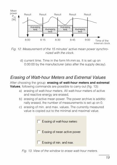
a) currenttransformerratio.The multiplier is used toThemultiplierisusedto recalculatethecurrentinthetransformerprimary side.Itissetupon1bythemanufacturer.b) voltagetransformerratio.The multiplier is used toThemultiplierisusedto recalculatethevoltageinthetransformerprimary side.Itissetupon1bythemanufacturer.c) waytosynchronizethemeanpower: - 15 minutes� walking window . mean power PAV-15minutes�walkingwindow.meanpowerPAV willberecalculatedforthelast15minutes,actualized every15seconds,i.e.walkingwindow,-measurementsynchronizedwiththeclockevery15,30 or60minutes-meanpowerPAVwillbeactualizedevery 15,30or60minutessynchronizedwiththeexternalreal clock(fig.12).Itissetuponthewalkingwindowbythemanufacturer.
��
Erasing of Watt-hour Meters and Extremal ValuesAfterchoosingthegroup:erasing of watt-hour meters and extremal Values,followingcommandsarepossibletocarryout(fig.13):
a) erasingofwatt-hourmeters.Allwatt-hourmetersofactive andreactiveenergyareerased,b) erasingofactivemeanpower.Thepowerarchiveisadditio nallyerased,thenumberofmeasurementsissetupon0.c) erasingofmin.andmax.values.Thecurrentlymeasured valueiscopiedouttotheminimalandmaximalvalue.
Fig. ��. View of the window to erase watt-hour meters.
Fig. ��. Measurement of the �� minutes’ active mean power synchro-nized with the clock.
d)currenttime.Timeintheformhh:mm:ss.Itissetupon 0:00:00bythemanufacturer(alsoafterthesupplydecay).

�0
Table1
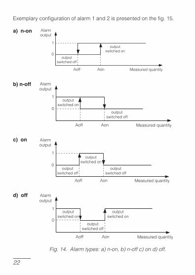
Setting of alarm parametersAfterchoosingthegroup:alarm 1 configurationoralarm 2 configura-tion,itispossibletoconfigurefollowingalarmparameters(fig.15):
a)assignmentofthealarmoutputparameter.kindofsignal,on whichthealarmacc.tothetable1hastoreact,
Thesetoftheinputquantityforalarmsandanalogoutputsisincludedinthetable1.Thecalculationwayisshowninexamplesinthechapter9.
Valueinreg-isters4010,4015,4020,
4026
KindofquantityValueforpercentagecalcula-
tionofalarmsandoutputvalues
00Lackofquantity/alarmoranalogoutputswitchedoff/
Lack
01 Voltageofphase1 Un[V]*
02 �urrentinthewireofphaseL1 In[A]*
03 ActivepowerofphaseL1 UnxInxcos(0°)[W]*
04 ReactivepowerofphaseL1 UnxInxsin(90°)[var]*
05 ApparentpowerofphaseL1 UnxIn[VA]*
06�oefficientofactivepowerofphaseL1
1
07 �oefficienttgjofphaseL1 1
08 Voltageofphase2 Un[V]*
09 �urrentinthewireofphaseL2 In[A]*
10 ActivepowerofphaseL2 UnxInxcos(0°)[W]*
11 ReactivepowerofphaseL2 UnxInxsin(90°)[var]*
12 ApparentpowerofphaseL2 UnxIn[VA]*
13�oefficientofactivepowerofphaseL2
1
14 �oefficienttgjofphaseL2 1
15 Voltageofphase3 Un[V]*
16 �urrentinthewireofphaseL3 In[A]*
17 ActivepowerofphaseL3 UnxInxcos(0°)[W]*
18 ReactivepowerofphaseL3 UnxInxsin(90°)[var]*

��
*Un,In.Ratedvaluesoftransducervoltageandcurrent
b) kindofthealarmoutputoperation.chooseonefrom6modes n-on,n-off,on,off,h-onandh-off.Workingmodeshavebeen presentedonthefig.14,c) lowervalueofalarmswitching.percentagevalueofthestate changeofthechosensignal,d) uppervalueofalarmswitching.percentagevalueofthestate changeofthechosen signal,chosensignal,e) switching delay of the alarm. ��elay time in seconds whenswitchingdelayofthealarm.��elay time in seconds when��elaytimeinsecondswhen switchingthealarmstatestate
Bothalarmsaresetupinthemoden-on.Caution! The setup of the value AoffThe setup of the value Aoff ³ Aon causes the alarm switching off.
19 ApparentpowerofphaseL3 UnxIn[VA]*
20�oefficientofactivepowerofphaseL3
1
21 �oefficienttgjofphaseL3 1
22 3-phasemeanvoltage Un[V]*
23 3-phasemeancurrent In[A]*
24 3-phaseactivepower(P1+P2+P3) 3xUnxInxcos(0°)[W]*
25 3-phasereactivepower(Q1+Q2+Q3) 3xUnxInxsin(90°)[var]*
26 3-phasereactivepower(S1+S2+S3) 3xUnxIn[VA]*
27Powerfactorof3-phaseactivepower
1
28 3-phasecoefficienttgj 1
29 Frequency 100[Hz]
30 Phase-to-phasevoltageL1-L2 3 Un[V]*
31 Phase-to-phasevoltageL2-L3 3 Un[V]*
32 Phase-to-phasevoltageL3-L1 3 Un[V]*
33Phase-to-phasevoltagemeanvoltage 3 Un[V]*
3415,30,60minutes�3-phaseactivepower 3xUnxInxcos(0°)[W]*
��
Exemplaryconfigurationofalarm1and2ispresentedonthefig.15.
a) n-on
b) n-off
c) on
d) off
Fig. ��. Alarm types: a) n-on, b) n-off c) on d) off.

��
Otheralarmtypes:h-on.alwaysswitchedon;h-off.alwaysswitchedoff.
Fig. ��. View of the configuration window of analog outputView of the configuration window of analog output
Setup of analog output parametersAfterchoosingthegroup:output 1oroutput 2,itispossibletoconfigurefollowingoutput parameters:outputparameters:
a) assignment of the parameter to the analog output. �ind ofassignmentoftheparametertotheanalogoutput.�ind of�indofsignal,onwhichtheoutputhastoreactacc.tothetable1,
b) lowervalueoftheinputrange.Percentagevalueofthechosensignal,
c) uppervalueoftheinputrange.Percentagevalueofthechosensignal,
d) lowervalueoftheoutputrange.OutputsignalvalueinmA,e) uppervalueoftheoutputrange.OutputsignalvalueinmA,

��
f) workingmodeoftheanalogoutput.Followingmodesareaccessible:normalworklowervalue,uppervalue.Bothalarmsaresetupinthenormalmodebythemanufacturer.
Anexemplaryconfigurationof theanalogoutput ispresentedon thefig.16.e)..
Fig. ��. View of the analog output configuration windowView of the analog output configuration window
Admissibleoverflowontheanalogoutput:20%ofthelowerandupperrangevalue.Minimalvalueontheanalogoutput:-20´1.2=-24mA.Maximalvalueontheanalogoutput:20´1.2=24mA.
Restoration of Manufacturer ParametersAfterchoosingthegroup:restoration of manufacturer parametersitispossibletorestorefollowingmanufacturersparameterssetinthetable2:

��
Table2
Parameter description Range/valueManufac-
turer value
Ratioofthecurrenttransformer
1...10000 1
Ratioofthevoltagetransformer
1...4000 1.0
Synchronizationoftheactivemeanpower:
-15minutes�walkingwindow(recordinginthearchiveevery15minutes)
-measurementsynchronizedwiththeclockevery15minutes,
-measurementsynchronizedwiththeclockevery30minutes,
-measurementsynchronizedwiththeclockevery60minutes,
walkingwindow
Hourx100+Minutes 0:00...23:59 0:00
QuantityontherelayoutputNo1
0...34(acc. to the table 1)acc.tothetable1)) 24
Outputtypeofthealarm1
n-on;n-off;on;off;h-on;h-off; n-on
Lowervalueofthealarm1switching
-120.0...120.0% 99.0%
Uppervalueofthealarm1switching
-120.0...120.0% 101.0%
Switchingdelayofthealarm1
0...300sekund 0
QuantityontherelayoutputNo2
0...34(acc. to the table 1)acc.tothetable1)) 23
Outputtypeofthealarm2
n-on;n-off;on;off;h-on;h-off; n-on
Lowervalueofthealarm2switching
-120.0...120.0% 99.0%
Uppervalueofthealarm2switching
-120.0...120.0% 101.0%

��
Switchingdelayofthealarm2
0...300 0
Quantityonthecon-tinuousNo1
0...34(acc. to the table 1)acc.tothetable1)) 24
Lowervalueoftheinputrangein%oftheratedrangeoftheinput
No1
-120.0...120.0% 0.0%
Uppervalueoftheinputrangein%oftheratedrangeoftheinput
No1
-120.0...120.0% 100.0%
Lowervalueoftheoutputrangeofthe
outputNo1-20.00...20.00mA 4.00mA
Lowervalueoftheoutputrangeofthe
outputNo10.01...20.00mA 20.00mA
Manualswitchingoftheanalogoutput1on::
normalwork,thelowervalueoftheoutput
rangeNo1issetuptheuppervalueoftheoutput
rangeNo1issetup..
normalwork
Quantityonthecon-tinuousNo2
0...34(acc. to the table 1)acc.tothetable1)) 23
Lowervalueoftheinputrangein%oftheratedrangeoftheinput
No2
-120.0...120.0% 0.0%
Uppervalueoftheinputrangein%oftheratedrangeoftheinput
No2
-120.0...120.0% 120.0%
Lowervalueoftheoutputrangeofthe
outputNo2-20.00...20.00mA 0mA

��
Measured ValuesAfterchoosingthegroup:-measured values,allparametersmeasuredbythetransduceraredisplayedintheformofalist(fig.17.).
Fig. ��. View of the window of the measured value group
Uppervalueoftheoutputrangeofthe
outputNo20.01...20.00mA 20mA
Manualswitchingoftheanalogoutput2::
normalwork,thelowervalueoftheoutput
rangeNo2issetup,theuppervalueoftheoutput
rangeNo2issetup..
normalwork
AddressintheMO��-BUSnetwork
1...247 1
Transmissionmode 8n2,8e1,8o1,8n1 8n2
Baudrate 4800,9600,19200,38400 9600

��
Minimal and Maximal ValuesAfterchoosingthegroup:-minimal and maximal values,minimalandmaximalvaluesofindividualparametersmeasuredbythetransducerintheformofalistaredisplayed(fig.18.).
Fig. ��. View of the window of the min. and max. value group
Archive of power profileAfterchoosingthegroup:-archive of power profile,followinginforma-tionisdisplayed:archiving frequency. frequency time tostore thevalueofaveragedpower(sample),numberofsamples,fromwhichsampletodisplayfromtherange1...961(fig.19).

��
Fig. ��. View of the window of the power profile archive group
Thedetaileddescriptionofarchiveoperationisdescribedinchapter6..
Information a�out thenformation a�out the DeviceAfterchoosingthegroup.infor-mation about the device,follow-ing information is displayed: Thedevice picture, serial number,programversion,andashortde-vicedescription
Fig. �0. View of the window of the information about the device group
FactoryNo:0809002Firmwarewersion:0.80

�0
6. �rch��e �� �ower �rof�le�rch��e �� �ower �rof�leTheP43transducerisequippedwithanarchiveallowingtostoreupto1000measurementsofaveragedactivepower.TheaveragedactivepowerPAVcanbearchivedwithtimeintervals15,30,60minutessyn-chronizedwiththerealtimeclock(0,15,30,45minutes.anexamplefor15minutesisshownonthefig.11).Incaseofworkinthemode:15minutes�walkingwindow,thearchivingisthesameasforthe15minutes�timeinterval(fig.12).Thearchiveisavai-lableintheformof1001registersintherangeofaddresses8000-9000.Thenumberofarchivedvaluesisintheregister8000,howevervalues(samples)arearchivedinregisterswithaddresses8001-9000.Values1e20areinregisters,inwhichsamplesarenotwrittenyet.Thearchiveisorganizedintheshapeofacircularbuffer.Afterwritingthethousandthvalue,thenextvalueoverwritestheoldestvaluewiththenumber1,andsuccessivelythenextwiththenumber2,etc.As longas thenumberofsamplesdoesnotexceed1000, thevaluein the register8000 indicates thenumberofarchivedsamples.Afterexceeding1000samples, thenumberofarchivedvalueschanges intherangefrom1000to2000.E.g.thevalue1006intheregister8000means,thattherewasmorethanathousandofsamplesandtheoldestsamplesarefromtheregister8007to9000,nextfrom8001totheyoun-gestsamplelocatedintheregister8006.Thechangeofthecurrentorvoltagetransformerratio,realtimeorthekindofmeanpowercausesthearchiveerasing.
7. error Codes
Afterconnectingthetransducertothenetwork,messagesabouterrorscanappear.�ausesoferrorsarepresentedbelow:-thestatediodepulsatesinred.lackofcalibrationorthenon-volatilememo-
ryisdamaged.One must return the transducer to the manufacturer,Onemustreturnthetransducertothemanufacturer,-thestatediodelightsinred.inappropriateworkparameters;onemust
configurethetransduceragain.-thestatediodepulsatealternatelyinredandgreen-errorofphaseconnectionseque-
nce;onemustinterchangetheconnectionofphaseL2withthephaseL3.

��
8. ser�al �nterfacesser�al �nterfaces
8.1. rs-485 �nterface �� set of �arametersl identifier 0xB4 (180)identifier 0xB4(180)l transducer address 1...247transduceraddress 1...247l baud rate 4.8, 9.6, 19.2, 38.4 kbit/sbaudrate 4.8,9.6,19.2,38.4kbit/sl working mode Modbus RTUworkingmode ModbusRTUl information unit 8N2, 8E1, 8O1, 8N1informationunit 8N2,8E1,8O1,8N1l maximal response time 1000 msmaximalresponsetime 1000mslmaximalnumberofbytes duringthereadout/write: 200bytesl implemented functions 03, 16, 17implementedfunctions 03,16,17 -03readoutofregisters, -16writeofregisters, -17deviceidentifying.Manufacturer�ssettings:address1,baudrate9600,modeRTU8N2.
8.2. usB �nterface �� set of �arametersl identifier 0xB4identifier 0xB4 0xB4l transducer address 1transduceraddress 1 1l baud rate 9.6 kbit/sbaudrate 9.6 kbit/s 9.6kbit/sl working mode Modbus RTUworkingmode Modbus RTU ModbusRTUl informationunit 8N2 8N2l maximal response time 1000 msmaximalresponsetime 1000 ms 1000mslmaximalnumberofbytes duringthereadout/write: 200bytesl implemented functions 03, 16, 17implementedfunctions 03, 16, 17 03,16,17 -03readoutofregisters, -16writeofregisters, -17deviceidentifying.
8.3. re��ster map of the �43 �ransducerIntheP43transducer,dataarelocatedin16-bitand32-bitregisters.Processvariablesandtransducerparametersarelocatedinthereg-isteraddressspaceinthewaydependingonthetypeofthevariable

��
valuetype.Bitsin16-bitregisterarenumberedinthewaydependingonthevariablevaluetype.Bitsin16-bitregistersarenumberedfromtheyoungertotheolder(b0-b15).32-bit registers contain numbers of32-bitregisterscontainnumbersoffloattypeintheIEEE-745standard.Registerrangesaresetinthetable3.16-bitregistersarepresentedinthetable4.32-bitregistersaresetin tables 5 and 6. Register addresses in tables 3,4,5,6 are physicaladdresses.
Table3Range of
addressesType of value
Description
1000.3001Float
(2x16bits)
Value located in two successive 16-bitregisters.Registerscontain thesamedataas32-bitregistersfromthearea8000.Registersonlyforreadout.
4000.4044Integer(16bits)
Value located in one 16-bit register. Thetable 3 contains the register description.Registersforwriteandreadout.
7000.7121Float
(2x16bits)
Value located in two successive 16-bitregisters.Registerscontain thesamedataas 32-bit registers from the area 7500.Registersforreadout.
7500.7560Float
(32bits)
Value located in one 32-bit register. Thetable4containsthedescriptionofregisters.Registersforreadout.
8000.9000Float
(32bits)
Valuelocatedinone32-bitregister.Theta-ble6contains thedescriptionof registers.Registersforreadout.
Table4Regi-ster ad-
dress
Ope-ra-
tionsRange Description
By De-fault
4000 RW 0 Reserved 0
4001 RW 0 Reserved 04002 RW 0 Reserved 04003 RW 1...10000 �urrenttransformerratio 14004 RW 1...40000 Voltagetransformerratiox0.1 10

��
4005 RW 0...3
Synchronizationofmeanactivepower:0.15minutes�walkingwindow
(recordingsynchronizedevery15minwiththeclock.)
1.measurementsynchronizedevery15minwiththeclock.
2.measurementsynchronizedevery30minwiththeclock.
3.measurementsynchronizedevery60minwiththeclock.
0
4006 RW 0.1 Erasingofenergywatt-hourmeters 0
4007 RW 0.1 ErasingofmeanactivepowerPAV 04008 RW 0.1 Erasingminandmax 04009 RW 0...2359 Hourx100+Minutes 0
4010 RW 0.1..34QuantityontherelayoutputNo1
/codeacc.tothetable1/0
4011 RW 0..5Outputtype:0.n-on,1.n-off,
2.on,3-oFF,4.h-on,5.h-oFF0
4012 RW-1200..0..1200
[o/oo]Lowerswitchingvalueofthe
alarmNo1(relay)990
4013 RW-1200..0..1200
[o/oo]Upperswitchingvalueofthe
alarmNo1(relay)1010
4014 RW 0..300s Switchingdelayofthealarm1 0
4015 RW 0.1..34QuantityontherelayoutputNo2
(codeacc.tothetable1)0
4016 RW 0..5Outputtype:0.n-on,1.n-off,
2.on,3-oFF,4.h-on,5.h-oFF0
4017 RW-1200...0...1200
[o/oo]Lowerswitchingvalueofthe
alarmNo2(relay)990
4018 RW-1200...0...1200
[o/oo]Upperswitchingvalueofthe
alarmNo2(relay)1010
4019 RW 0...300s Switchingdelayofthealarm2 0
4020 RW 0.1...34QuantityonthecontinuousoutputNo
1(codeacc.tothetable1)0
4021 RW-1200...0...1200
[o/oo]Lowervalueoftheinputrangein[o/oo]oftheratedinputrangeNo1
0

��
4022 RW-1200...0...1200
[o/oo]Uppervalueoftheinputrangein[o/oo]oftheratedinputrangeNo1
1200
4023 RW-2000...0...2000
[10mA]Lowervalueoftheoutputrange
oftheoutputNo1[10µA]400
4024 RW 1...2000[10mA]Uppervalueoftheoutputrange
oftheoutputNo12000
4025 RW 0...2
Manualswitchingonoftheanalogoutput1:0.normalwork,1.valuesetfromtheregister4023,2-valuemadefromtheregister4024
0
4026 RW 0.1...34Quantityonthecontinuousoutput
No2(codeacc.tothetable1)0
4027 RW-1200...0...1200
[o/oo]
Lowervalueoftheinputrangein[o/oo]oftheratedrangeofthe
inputNo20
4028 RW-1200...0...1200
[o/oo]
Uppervalueoftheinputrangein[o/oo]oftheratedrangeofthe
inputNo21200
4029 RW-2000...0...2000
[10mA]Lowervalueoftheoutputrange
oftheoutputNo2[10µA]400
4030 RW 1...2000[10mA]Uppervalueoftheoutputrange
oftheoutputNo2[10µA]2000
4031 RW 0..2
Manualswitchingonoftheanalogoutput2:0.normalwork,
1.valuesetfromtheregister4029,2-valuesetfromtheregister4030
0
4032 RW 1...247 AddressintheMO��BUSnetwork 1
4033 RW 0...3Transmissionmode:0->8n2,
1->8e1,2->8o1,3->8n10
4034 RW 0...3Baudrate:0->4800,1->9600
2->19200,3->384001
4035 RW 0,1Updatethechangeoftransmis-
sionparameters0
4036 RW 0,1 Record of standard parametersecordofstandardparameters 0
4037 R 0...15258Activeinputenergy,twoolder
bytes*0

��
Inparenthesis[]:resolutionorunitissuitablyplaced.
EnergiesarerenderaccessibleinhundredsofWatt-hours(Var-hours)intwo16-bitregistersandforthisreasonwhenrecalculatingvaluesofeachenergyfromregisters,onemustdividethemby 10, i.e:by10,i.e:
Activeinputenergy=(valueofregister.4034*65536+valueofregister4038)/10[kWh]
Activeoutputenergy=(valueofregister.4045*65536+valueofregister4046)/10[kWh]
Reactiveinductiveenergy=(valueofregister4039*65536+valueofregister4040)/10[kVarh]
Reactivecapactiveenergy=(valueofregister4047*65536+valueofregister4048)/10[kVarh]
4038 R 0...65535 Activeinputenergy,twoyoungerbytes* 0
4039 R 0...15258Reactiveinductiveenergy,two
olderbytes*0
4040 R 0...65535Reactiveinductiveenergy,two
youngerbytes*0
4041 R 0...65535Statusregister.description
below0
4042 R 0...65535 Serialnumber,twoolderbytes* 0
4043 R 0...65535Serialnumber,twoyounger
bytes*0
4044 R 0...65535 Programversion(x100) 100
4045 R 0...15258Activeenergyoutput,twoolder
bytes*0
4046 R 0...65535Activeenergyoutput,two
youngerbytes*0
4047 R 0...15258Reactivecapacitiveenergy,two
olderbytes*0
*availablefromtheprogramversion1.02.Inpriorversions,registers4037-4040includeenergiesfromaddedmodulesofparticularener-gies.

��
Bit9 Bit8 Voltage rangeVoltagerange 0 0 57,8 V�57,8V� 0 1 230 V�230V�
Bit7.„1”.the interval of power averaging is not elapsedtheintervalofpoweraveragingisnotelapsedBit6.„1”.reservedreservedBit5.„1”.too low voltage to measure the frequencytoolowvoltagetomeasurethefrequencyBit4.„1”.too little voltage of phase �toolittlevoltageofphase ��Bit3.„1”.too little voltage of phase Btoolittlevoltageofphase BBBit2.„1”.too little voltage of phase Atoolittlevoltageofphase AABit1.relay output state „2” . On, „0” - offrelayoutputstate „2” . On, „0” - off„2”.On,„0”-offBit0.relay output state „1” . On, „0” - offrelayoutputstate „1” . On, „0” - off„1”.On,„0”-off
Statusregister:Bit15.„1”.damage of non-volatile memorydamageofnon-volatilememoryBit14.„1”.lack of calibration or erroneous calibrationlackofcalibrationorerroneouscalibrationBit13.„1”.error of parameter valueserrorofparametervaluesBit12.„1”.error of energy valueserrorofenergyvaluesBit11.„1”.reservedreservedBit10.current range „0” . 1 A�; 1” . 5 A�currentrange „0” . 1 A�; 1” . 5 A�„0”.1A�;1”.5A�
Table5
Ad-dress of 16
bit regi-sters
Ad-dress of 16
bit regi-sters
Ope-ra-
tionsDescription Unit
7000 7500 R Voltageofphase L1L1 V
7002 7501 R �urrentofphase L1L1 A
7004 7502 R Activepowerofphase L1L1 W
7006 7503 R Reactivepowerofphase L1L1 Var
7008 7504 R Apparentpowerofphase L1L1 VA
7010 7505 R Activepowerfactorofphase L1L1 -
7012 7506 RReactivepowertoactivepowerratioofphase L1L1
-
7014 7507 R Voltageofphase L2L2 V

��
7016 7508 R �urrentofphase L2L2 A
7018 7509 R Activepowerofphasefazy L2L2 W
7020 7510 R Reactivepowerofphase L2L2 Var
7022 7511 R Apparentpowerofphase L2L2 VA
7024 7512 R Activepowerfactorofphase L2L2 -
7026 7513 RReactivepowertoactivepowerratioofphase L2L2
-
7028 7514 R Voltageofphase L3L3 V
7030 7515 R �urrentofphase L3L3 A
7032 7516 R Activepowerofphasefazy L3L3 W
7034 7517 R Reactivepowerofphase L3L3 Var
7036 7518 R Apparentpowerofphase L3L3 VA
7038 7519 R Activepowerfactorofphase L3L3 -
7040 7520 RReactivepowertoactivepowerratioofphase L3L3
-
7042 7521 R Mean3-phasevoltage V
7044 7522 R Mean3-phasecurrent A
7046 7523 R 3-phaseactivepower(P1+P2+P3) W
7048 7524 R 3-phasereactivepower(Q1+Q2+Q3) Var
7050 7525 R 3-phaseapparentpower(S1+S2+S3) VA
7052 7526 R Meanactivepowerfactor -
7054 7527 RMeanratioofreactivepowertoactivepower
-
7056 7528 R Frequency Hz
7058 7529 R Phase-to-phasevoltage L1-L2L1-L2 V
7060 7530 R Phase-to-phasevoltage L2-L3L2-L3 V
7062 7531 R Phase-to-phasevoltage L3-L1L3-L1 V
7064 7532 R Meanphase-to-phasevoltage V
7066 7533 R15,30,60minutes�3-phaseact.power(P1+P2+P3)
W
7068 7534 R Reserved
7070 7535 R Reserved
7072 7536 R Min.mean3-phasevoltage V
7074 7537 R Max.mean3-phasevoltage V
��
7076 7538 R Min.mean3-phasecurrent A
7078 7539 R Max.mean3-phasecurrent A
7080 7540 R Min.3-phaseactivepower W
7082 7541 R Max.3-phaseactivepower W
7084 7542 R Min.3-phasereactivepower Var
7086 7543 R Max.3-phasereactivepower Var
7088 7544 R Min.3-phaseapparentpower VA
7090 7545 R Max.3-phaseapparentpower VA
7092 7546 R Min.activepowerfactor -
7094 7547 R Max.activepowerfactor -
7096 7548 RMin.meanratioofreactivepowertoactivepower
-
7098 7549 RMax.meanratioofreactivepowertoactivepower
-
7100 7550 R Min.frequence Hz
7102 7551 R Max.frequence Hz
7104 7552 R Min.meanphase-to-phasevoltage V
7106 7553 R Max.meanphase-to-phasevoltage V
7108 7554 R Min.meanactivepower W
7110 7555 R Max.meanactivepower W
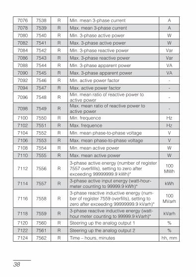
7112 7556 R3-phaseactiveenergy(numberofregister7557overfillls),settingtozeroafterexceeding99999999.9kWh)*
100MWh
7114 7557 R3-phaseactiveinputenergy(watt-hour-metercountingto99999.9kWh)*
kWh
7116 7558 R3-phasereactiveinductiveenergy(num-berofregister7559overfills),settingtozeroafterexceeding99999999.9kVarh)*
100MVarh
7118 7559 R3-phasereactiveinductiveenergy(watt-hourmetercountingto99999.9kVarh)*
kVarh
7120 7560 R Steeringuptheanalogoutput1 %
7122 7561 R Steeringuptheanalogoutput2 %
7124 7562 R Time.hours,minutes hh,mm
��
Incaseofaloweroverflow,thevalue.1e20iswrittenin,howeverincaseofanupperoverfloworifanerroroccurs,thevalue1e20iswrittenin.
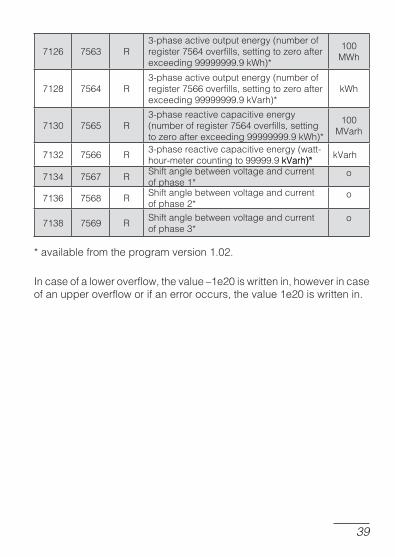
7126 7563 R3-phaseactiveoutputenergy(numberofregister7564overfills,settingtozeroafterexceeding99999999.9kWh)*
100MWh
7128 7564 R3-phaseactiveoutputenergy(numberofregister7566overfills,settingtozeroafterexceeding99999999.9kVarh)*
kWh
7130 7565 R3-phasereactivecapacitiveenergy(numberofregister7564overfills,settingtozeroafterexceeding99999999.9kWh)*
100MVarh
7132 7566 R3-phasereactivecapacitiveenergy(watt-hour-metercountingto99999.9kVarh)*kVarh)*)*
kVarh
7134 7567 RShiftanglebetweenvoltageandcurrentofphase1*
o
7136 7568 RShiftanglebetweenvoltageandcurrentofphase2*
o
7138 7569 RShiftanglebetweenvoltageandcurrentofphase3*
o
*availablefromtheprogramversion1.02.

�0
Address of 16 bit registers
Address of 32 bit registers
Ope-ra-
tionsDescription
1000 8000 R Numberofarchivedvalues
1002 8001 R Archivedvaluewithnumber1
1004 8002 R Archivedvaluewithnumber2
... ... ... ...
3000 9000 R Archivedvaluewithnumber1000
Table6
9. examples of �43 �ransducer �ro�ramm�n�
Example 1 – Programming an Alarm with Hysteresis
Programtheoperationofthealarm1insuchaway,thatatthevalue250Vofthephase1voltage,thealarmwillbeswitchedon,howeverswitchedoffatthevalue210V.Fortherated230Vexecution,onemustsetupvaluesfromthetable7.
Regi-ster Value Meaning
4010 1 1.voltageofphase14011 0 0.n-onmode
4012 913
913.91.3%(percentagevaluewithoneplaceafterthedecimalpointmultipliedby10)oftheratedvoltageofphase1.alarmswitchedoff,(210V/230V)x1000=913
4013 1087
1087.108.7%(percentagevaluewithoneplaceafterthedecimalpointmultipliedby10)oftheratedvoltageofphase1.alarmswitchedon,(250V/230V)x1000=1087
4014 0 0.0seconddelayinthealarmswitching
Table7

��
Example 2 – Programming a Unidirectional Continuous OutputProgramthecontinuousoutput1operationinsuchawaythat,atthevalue4Aofthemeanthree-phasecurrent,thevalue20mAwasontheoutput,howeveratthevalue0Aofthemeanthree-phasecurrent,thevalue4mAwasontheoutput.For the rated execution 5 A, one must set values from the table 8.:
Regi-ster
Value Meaning
4020 23 23.mean3-phasecurrent(I)
4021 0
0.0.0%(percentagevaluewithoneplaceafterthedecimalpointmultipliedby10)thelowervalueoftheratedmean3-phasecurrent,(0A/5A)x1000=0
4022 800
800.80.0%(percentagevaluewithoneplaceafterthedecimalpointmultipliedby10)theuppervalueoftheratedmean3-phasecurrent,(4A/5A)x1000=800
4023 400400.4.00mA(valueinmAwithtwoplacesafterthedecimalpointmultipliedby100)lowervalueoftheoutputcurrent
4024 2000
2000.20.00mA(valueinmAwithtwoplacesafterthedecimalpointmultipliedby100)uppervalueoftheoutputcurrent.(20.00mAx100)=2000
4025 0 0.normalmodeofthecontinuousoutput1
Table8
Example 3 – Programming a Bidirectional Continuous OutputProgramthecontinuousoutput1operationinsuchawaythat,atthethree-phasepowervalue3x4Ax230Vxcos(180°)=-2760W,thevalue.20mAwasontheoutput,however for thethree-phasepowervalue3x4Ax230Vxcos(0°)=2760W,thevalue.20mAwasontheoutput.

��
Regi-ster
Value Meaning
4020 24 24.3-phasepower(P)
4021 -800
-100.-100.0%(percentagevaluewithoneplaceafterthedecimalpointmultipliedby10)thelowervalueoftherated3-phasepower,(3x4Ax230Vxcos(180°)/3x5Ax230V)x1000=-800
4022 800
1000.100.0%(percentagevaluewithoneplaceafterthedecimalpointmultipliedby10)theuppervalueoftherated3-phasepower,(3x4Ax230Vxcos(0°)/3x5Ax230V)x1000=800
4023 -2000
-2000.-20.00mA(valueinmAwithtwoplacesafterthedecimalpointmultipliedby100)lowervalueoftheoutputcurrent.(20.00mAx100)=-2000
4024 2000
2000.20.00mA(valueinmAwithtwoplacesafterthedecimalpointmultipliedby100)uppervalueoftheoutputcurrent.(20.00mAx100)=2000
4025 0 0.normalmodeofthecontinuousoutput1
Table9
Fortheratedexecution3x5/230V,onemustsetvaluesfromthetable9

��
10. �eC���C�� d����eC���C�� d���
Measuring Ranges and Admissible Basic ErrorsTable10
Measured quantity
Measuring range L1 L2 L3 S Basic error
�urrent1/5AL1...L3 0.02...6A� l l l ±0.2%
VoltageL-N 2.9...276V� l l l ±0.2%VoltageL-L 10...480V� l l l ±0.5%
Frequency 45.0...100.0Hz l l l ±0.2%
Activepower -1.65kW...1.4W...1.65kW l l l l ±0.5%
Reactivepower -1.65kvar...1.4var...1.65kvar l l l l ±0.5%
Apparentpower 1.4VA...1.65kVA l l l l ±0.5%Tangensj -1.2...0...1.2 l l l l ±1%PFfactor -1...0...1 l l l l ±0.5%
AnglebetweenUandI
-180o...180o l l l ±0.5%
Inputactiveenergy
0...99999999.9kWh l ±0.5%
��evelopedactiveenergy
0...99999999.9kWh l ±0.5%
Reactiveinductiveenergy
0...99999999.9kvarh l ±0.5%
Reactivecapaciti-veenergy
0...99999999.9kvarh l ±0.5%
Power Consumption��-in supply circuitinsupplycircuit 6VA-in voltage circuitinvoltagecircuit 0,05VA-in current circuitincurrentcircuit 0,05VA
Analog Outputs� 2programmableoutputs: -20...0...+20mA,Robc:0..500W accuracy0.2%
Relay Outputs� 2relays,voltagelessNOcontacts loadcapacity250V/0,5A
��
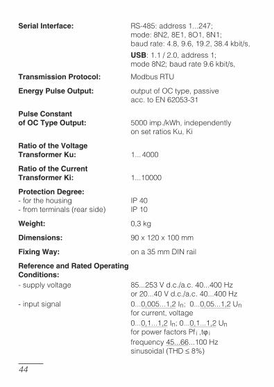
Serial Interface� RS-485:address1...247; mode:8N2,8E1,8O1,8N1; baudrate:4.8,9.6,19.2,38.4kbit/s,
USB:1.1/2.0,address1; mode8N2;baudrate9.6kbit/s,
Transmission Protocol� ModbusRTU
Energy Pulse Output� outputofO�type,passive acc.toEN62053-31
Pulse Constant of OC Type Output� 5000imp./kWh,independently onsetratios�u,�i
Ratio of the Voltage Transformer Ku� 1... 4000
Ratio of the Current Transformer Ki� 1...10000
Protection Degree�-forthehousing IP40-fromterminals(rearside) IP10
Weight� 0,3kg
Dimensions� 90x120x100mm
Fixing Way� ona35mm��INrail
Reference and Rated Operating Conditions�-supplyvoltage 85...253Vd.c./a.c.40...400Hz or20...40Vd.c./a.c.40...400Hz-inputsignal 0...0,005...1,2In;0...0,05...1,2Un forcurrent,voltage 0...0,1...1,2In;0...0,1...1,2Un forpowerfactorsPfi,tj i frequency45...66...100Hz sinusoidal(TH��8%)

��
-powerfactor -1...0...1-analogoutputs -24...-20...0...+20...24mA-ambient temperature -10...ambienttemperature -10... -10...23...+55°�-storage temperature -30...+70storagetemperature -30...+70 -30...+70°�-relative humidity 25...95% (inadmissible condensation)relativehumidity 25...95% (inadmissible condensation) 25...95%(inadmissible condensation)inadmissiblecondensation))-admissiblepeakfactor:
-current 2-voltage 2
-externalmagneticfield 0...40...400A/m-shortdurationoverload5sec.
-voltage inputs 2Un (max.1000 V)voltageinputs 2Un (max.1000 V) 2Un(max.1000V)-current inputs 10 Incurrentinputs 10 In 10In
-work position anyworkposition any any-preheating time 5 min.preheatingtime 5 min. 5min.
Additional errors�inpercentageofthebasicerror:-fromfrequencyofinputsignals <50%-fromambienttemperaturechanges <50%/10°�-forTH��>8% < 100% <100%
Standards Fulfilled by the Meter
Electromagnetic Compatibility::lnoise immunity acc. to EN 61000-6-2noiseimmunity acc.toEN61000-6-2lnoise emission acc. to EN 61000-6-4noiseemission acc.toEN61000-6-4
Safety Requirements::AccordingtoEN61010-1standardlisolationbetweencircuits basic basicbasiclinstallationcategory III, III,lpollutionlevel 2, 2,lmaximalphase-to-hearth
voltage 300 V 300Vlaltitudeabovesealevel < 2000 m, <2000m,
��
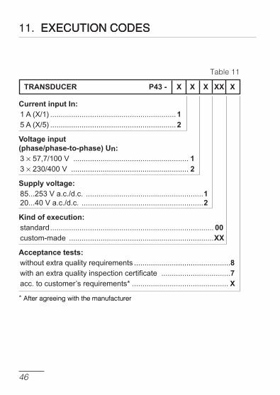
11. e�eCu���� C�dese�eCu���� C�des
Table11
TRANSDUCER P43- X X X XX X
CurrentinputIn:1 A (X/1) ............................................................15 A (X/5) ............................................................2
Voltageinput(phase/phase-to-phase)Un:3 ´ 57,7/100 V ....................................................... 13 ´ 230/400 V ........................................................ 2
Supplyvoltage:85...253 V a.c./d.c. ........................................................120...40 V a.c./d.c. ..........................................................2
Kindofexecution:standard .............................................................................. 00custom-made .....................................................................XX
Acceptancetests:without extra quality requirements ..............................................8with an extra quality inspection certificate .................................7acc. to customer’s requirements* .............................................. X
*After agreeing with the manufacturerAfteragreeingwiththemanufacturer
��
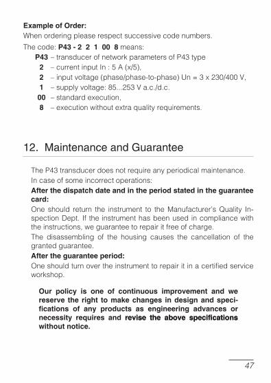
Example of Order�Whenorderingpleaserespectsuccessivecodenumbers.
Thecode:P43 - 2 2 1 00 8means: P43.transducerofnetworkparametersofP43type 2 .currentinputIn:5A(x/5), 2 .inputvoltage(phase/phase-to-phase)Un=3x230/400V, 1 .supplyvoltage:85...253Va.c./d.c. 00 .standardexecution, 8 .executionwithoutextraqualityrequirements.
12. ma�ntenance and Guarantee
TheP43transducerdoesnotrequireanyperiodicalmaintenance.Incaseofsomeincorrectoperations:After the dispatch date and in the period stated in the guarantee card�Oneshould return the instrument to theManufacturer�sQuality In-spection��ept. If theinstrumenthasbeenusedincompliancewiththeinstructions,weguaranteetorepairitfreeofcharge.The disassembling of the housing causes the cancellation of thegrantedguarantee.After the guarantee period�Oneshouldturnovertheinstrumenttorepairitinacertifiedserviceworkshop.
Our policy is one of continuous improvement and we reserve the right to make changes in design and speci-fications of any products as engineering advances or necessity requires and revise the above specificationsrevise the above specifications without notice.

��

��

�0
P43
-09B
30.
06.2
011
SALES PROGRAM��IGITALandBARGRAPHPANELMETERSMEASURINGTRANS��U�ERSANALOGPANELMETERS(��ININSTRUMENTS)��IGITAL�LAMP-ONMETERS IN��USTRIALPRO�ESSandPOWER�ONTROLLERS�HARTandPAPERLESSRE�OR��ERS1-PHASEand3-PHASEWATT-HOURMETERSLARGESIZE��ISPLAYPANELSELEMENTSOFINTEGRATIONSYSTEMSA��ESSORIESforMEASURINGINSTRUMENTS(SHUNTS)�USTOM-MA��EPRO��U�TSA��OR��ING�USTOMER�SREQUIREMENTS
WE ALSO OFFER OUR SERVICES IN THE PRODUCTION OF:ALUMINIUMALLOYPRESSURE�ASTINGSPRE�ISIONENGINEERINGandTHERMOPLASTI�SPARTSSUB�ONTRA�TINGofELE�TRONI���EVI�ES(SMT)PRESSURE�ASTINGSandOTHERTOOLS
LubuskieZak³adyAparatówElektrycznychLUMELS.A.ul. Sulechowska 1, 65-022 Zielona Góra, Poland
Tel.: (48-68) 329 51 00 (exchange)Fax: (48-68) 329 51 01e-mail:[email protected]://www.lumel.com.pl
ExportDepartment:Tel.: (48-68) 329 53 02Fax: (48-68) 325 40 91e-mail: [email protected]
MEASUREMENTCONTROLRECORDING
QUALITY PROCEDURES:According to ISO 9001 and ISO 14001 international requirements.�ll our �nstruments ha�e Ce mark.for more �nformat�on, please wr�te to or phone our export department