transcend wireless real estate consultant
TRANSCRIPT

Transcend Wireless
48 Spruce Street
Oakland, NJ 07436
Phone: (845) 401-0965
Gina Rappa
Real Estate Consultant
March 4, 2014
Hand Delivered
Ms. Linda Roberts
Executive Director
Connecticut Siting Council
10 Franklin Square
New Britain, CT 06051
RE: T-Mobile Northeast LLC notice of intent to modify an existing telecommunications
facility located at119 Tanner Marsh Road, Guilford CT, 06437. Known to T-Mobile
Northeast LLC as site CT11028A.
Dear Ms. Roberts:
In order to accommodate technological changes, implement Global System for Mobile
Communications Access (“GSM”) and/or Long Term Evolution (“LTE”) capabilities,
and enhance system performance in the state of Connecticut, T-Mobile Northeast LLC
plans to modify the equipment configurations at many of its existing cell sites. Please
accept this letter and attachments as notification, pursuant to R.C.S.A. Section 16-50j-73,
of construction which constitutes an exempt modification pursuant to R.C.S.A. Section
16-50j-72(b)(2). In compliance with R.C.S.A. Section 16-50j-73, a copy of this letter and
its attachments is being sent to the chief elected official of the municipality in which
affected cell site is located.
GSM employs Spread-Spectrum technology and special coding scheme to allow multiple
users to be multiplexed over the same physical channel. LTE is a new high-performance
air interface for cellular mobile communications. It is designed to increase the capacity
and speed of mobile telephone networks.
As part of the project the new multi-mode 800/1900 antenna will replace existing
antennas. These antennas will provide more flexibility for optimization by allowing fast
and easy electrical tilt adjustment from remote location and will enable the transmission
of multiple technologies from a single antenna. As T-Mobile Northeast LLC network
evolves to meet the demands of its customers, it is essential for T-Mobile Northeast LLC
to install modern equipment and antennas in order to provide reliable wireless voice and
data services. The proposed equipment will include multi-mode radios that will allow T-
Mobile Northeast LLC to transmit at different frequencies using different technologies,
including LTE technology. Likewise, the proposed antennas are quad-pole multi-band

high gain antennas that will allow T-Mobile Northeast LLC to operate using its multiple
frequency bands and technologies, including LTE technology. The proposed equipment
and antennas will improve the reliability, coverage and capacity of T-Mobile Northeast
LLC voice and data networks across T-Mobile Northeast LLC various FCC licensed
frequency bands and significantly increase the data speeds of T-Mobile Northeast LLC ’s
network by utilizing the latest LTE technology. Without the proposed modifications T-
Mobile Northeast LLC will be unable to provide reliable wireless voice and data service
using the latest technologies.
T-Mobile Northeast LLC will have an interim (testing) period during the
modification/installation prior to the final configuration. This antenna configuration is
shown on the attached drawings of the planned modifications. Also included is the
power density calculation reflecting the change in T-Mobile Northeast LLC operations at
the site and documentation of the structural sufficiency of the tower to accommodate the
revised antenna configuration.
The changes to the facility do not constitute modification as defined Connecticut General
Statues (“C.G.S.”) Section 16-50i(d) because the general physical characteristics of the
facility will not be significantly changed or altered. Rather, the planned changes to the
facility fall squarely within those activities explicitly provided for the R.C.S.A. Section
16-50j-72(b)(2).
1. The height of the overall structure will not be affected.
2. The proposed changes will not extend the site boundaries. There will be no
effect on the site compound.
3. The proposed changes will not increase the noise level at the existing facility
by 6 decibels or more.
4. Radio Frequency power density may increase due to the use of one or more
GSM transmissions. Moreover, LTE will utilize additional radio frequencies
newly licensed by the FCC for cellular mobile communications. However, the
changes will not increase the calculated “worst case” power density for the
combined operations at the site to a level at or above the applicable standard
for uncontrolled environments as calculated for a mixed frequency site.
For the foregoing reasons T-Mobile Northeast LLC respectfully submits that the
proposed changes at the referenced site constitute exempt modifications under
R.C.S.A. Section 16-50j-72(b)(2).
Please feel free to call me at (845) 401-0965 or email
[email protected] with questions concerning this matter.
Thank you for your consideration.
Sincerely,
Gina Rappa
(845) 401-0965

EBI Consulting environmental | engineering | due diligence
21 B Street .
Burlington, MA 01803 .
Tel: (781) 273.2500 .
Fax: (781) 273.3311
RADIO FREQUENCY EMISSIONS ANALYSIS REPORT EVALUATION OF HUMAN EXPOSURE POTENTIAL
TO NON-IONIZING EMISSIONS
T-Mobile Existing Facility
Site ID: CT11028A
Guilford SNET (ATC) 119 Tanner Marsh Road
Guilford, CT 06437
February 23, 2014

EBI Consulting environmental | engineering | due diligence
21 B Street .
Burlington, MA 01803 .
Tel: (781) 273.2500 .
Fax: (781) 273.3311
February 23, 2014
T-Mobile USA
Attn: Jason Overbey, RF Manager
35 Griffin Road South
Bloomfield, CT 06002
Re: Emissions Values for Site: CT11028A - Guilford SNET (ATC)
EBI Consulting was directed to analyze the proposed T-Mobile facility located at 119 Tanner Marsh
Road, Guilford, CT, for the purpose of determining whether the emissions from the Proposed T-Mobile
Antenna Installation located on this property are within specified federal limits.
All information used in this report was analyzed as a percentage of current Maximum Permissible
Exposure (% MPE) as listed in the FCC OET Bulletin 65 Edition 97-01and ANSI/IEEE Std C95.1. The
FCC regulates Maximum Permissible Exposure in units of microwatts per square centimeter (µW/cm2).
The number of µW/cm2 calculated at each sample point is called the power density. The exposure limit
for power density varies depending upon the frequencies being utilized. Wireless Carriers and Paging
Services use different frequency bands each with different exposure limits, therefore it is necessary to
report results and limits in terms of percent MPE rather than power density.
All results were compared to the FCC (Federal Communications Commission) radio frequency exposure
rules, 47 CFR 1.1307(b)(1) – (b)(3), to determine compliance with the Maximum Permissible Exposure
(MPE) limits for General Population/Uncontrolled environments as defined below.
General population/uncontrolled exposure limits apply to situations in which the general public may be
exposed or in which persons who are exposed as a consequence of their employment may not be made
fully aware of the potential for exposure or cannot exercise control over their exposure. Therefore,
members of the general public would always be considered under this category when exposure is not
employment related, for example, in the case of a telecommunications tower that exposes persons in a
nearby residential area.
Public exposure to radio frequencies is regulated and enforced in units of microwatts per square
centimeter (µW/cm2). The general population exposure limit for the cellular band is 567 µW/cm2, and the
general population exposure limit for the PCS band is 1000 µW/cm2. Because each carrier will be using
different frequency bands, and each frequency band has different exposure limits, it is necessary to report
percent of MPE rather than power density.
EBI Consulting environmental | engineering | due diligence
21 B Street .
Burlington, MA 01803 .
Tel: (781) 273.2500 .
Fax: (781) 273.3311
Occupational/controlled exposure limits apply to situations in which persons are exposed as a
consequence of their employment and in which those persons who are exposed have been made fully
aware of the potential for exposure and can exercise control over their exposure. Occupational/controlled
exposure limits also apply where exposure is of a transient nature as a result of incidental passage through
a location where exposure levels may be above general population/uncontrolled limits (see below), as
long as the exposed person has been made fully aware of the potential for exposure and can exercise
control over his or her exposure by leaving the area or by some other appropriate means.
Additional details can be found in FCC OET 65.
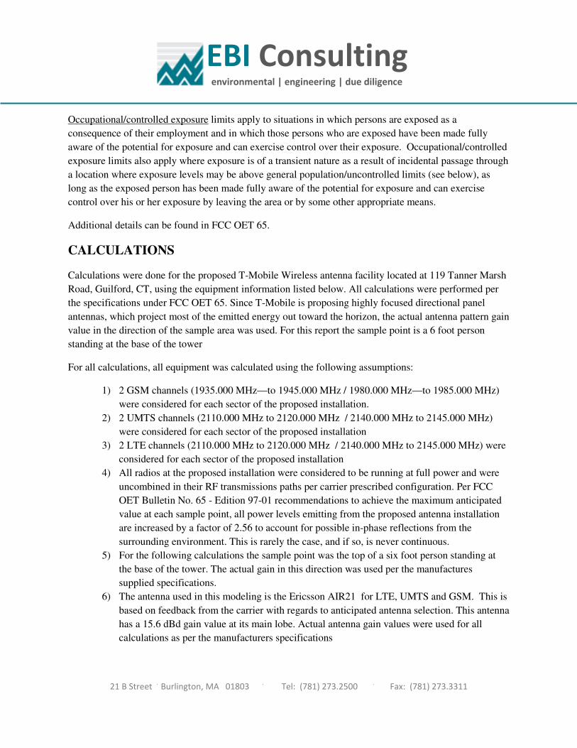
CALCULATIONS
Calculations were done for the proposed T-Mobile Wireless antenna facility located at 119 Tanner Marsh
Road, Guilford, CT, using the equipment information listed below. All calculations were performed per
the specifications under FCC OET 65. Since T-Mobile is proposing highly focused directional panel
antennas, which project most of the emitted energy out toward the horizon, the actual antenna pattern gain
value in the direction of the sample area was used. For this report the sample point is a 6 foot person
standing at the base of the tower
For all calculations, all equipment was calculated using the following assumptions:
1) 2 GSM channels (1935.000 MHz—to 1945.000 MHz / 1980.000 MHz—to 1985.000 MHz)
were considered for each sector of the proposed installation.
2) 2 UMTS channels (2110.000 MHz to 2120.000 MHz / 2140.000 MHz to 2145.000 MHz)
were considered for each sector of the proposed installation
3) 2 LTE channels (2110.000 MHz to 2120.000 MHz / 2140.000 MHz to 2145.000 MHz) were
considered for each sector of the proposed installation
4) All radios at the proposed installation were considered to be running at full power and were
uncombined in their RF transmissions paths per carrier prescribed configuration. Per FCC
OET Bulletin No. 65 - Edition 97-01 recommendations to achieve the maximum anticipated
value at each sample point, all power levels emitting from the proposed antenna installation
are increased by a factor of 2.56 to account for possible in-phase reflections from the
surrounding environment. This is rarely the case, and if so, is never continuous.
5) For the following calculations the sample point was the top of a six foot person standing at
the base of the tower. The actual gain in this direction was used per the manufactures
supplied specifications.
6) The antenna used in this modeling is the Ericsson AIR21 for LTE, UMTS and GSM. This is
based on feedback from the carrier with regards to anticipated antenna selection. This antenna
has a 15.6 dBd gain value at its main lobe. Actual antenna gain values were used for all
calculations as per the manufacturers specifications

EBI Consulting environmental | engineering | due diligence
21 B Street .
Burlington, MA 01803 .
Tel: (781) 273.2500 .
Fax: (781) 273.3311
7) The antenna mounting height centerline of the proposed antennas is 175 feet above ground
level (AGL)
8) Emissions values for additional carriers were taken from the Connecticut Siting Council
active database. Values in this database are provided by the individual carriers themselves.
All calculation were done with respect to uncontrolled / general public threshold limits
Site ID
Site Addresss
Site Type
Antenna
Number Antenna Make Antenna Model Status Frequency Band Technology
Power
Out Per
Channel
(Watts)
Number of
Channels
Composite
Power
Antenna Gain
in direction
of sample
point (dBd)
Antenna
Height (ft)
analysis
height Cable Size
Cable Loss
(dB)
Additional
Loss ERP
Power
Density
Value
Power
Density
Percentage
1a Ericsson AIR21 B4A/B2P Active AWS - 2100 MHz LTE 60 2 120 -3.95 175 169 None 0 0 48.326044 0.608294 0.06083%
1b Ericsson AIR21 B4A/B2P Not Used - - 0 -3.95 175 169 None 0 0 0 0 0.00000%
2a Ericsson AIR21 B2A / B4P Active PCS - 1950 MHz GSM / UMTS 30 2 60 -3.95 175 169 1-5/8" 0 0 24.163022 0.304147 0.03041%
2B Ericsson AIR21 B2A / B4P Passive AWS - 2100 MHz UMTS 30 2 60 -3.95 175 169 1-5/8" 0 0 24.163022 0.304147 0.03041%
0.122%
Antenna
Number Antenna Make Antenna Model Status Frequency Band Technology
Power
Out Per
Channel
(Watts)
Number of
Channels
Composite
Power
Antenna Gain
in direction
of sample
point (dBd)
Antenna
Height (ft)
analysis
height Cable Size
Cable Loss
(dB)
Additional
Loss ERP
Power
Density
Value
Power
Density
Percentage
1a Ericsson AIR21 B4A/B2P Active AWS - 2100 MHz LTE 60 2 120 -3.95 175 169 None 0 0 48.326044 0.608294 0.06083%
1b Ericsson AIR21 B4A/B2P Not Used - - 0 -3.95 175 169 None 0 0 0 0 0.00000%
2a Ericsson AIR21 B2A / B4P Active PCS - 1950 MHz GSM / UMTS 30 2 60 -3.95 175 169 1-5/8" 0 0 24.163022 0.304147 0.03041%
28 Ericsson AIR21 B2A / B4P Passive AWS - 2100 MHz UMTS 30 2 60 -3.95 175 169 1-5/8" 0 0 24.163022 0.304147 0.03041%
0.122%
0.280%
WGRS - Town of Monroe 7.180%
Sector total Power Density Value:
Site Composite MPE %
Total Site MPE % 92.325%
TCI (10 Tanner Marsh) 0.010%
MPE %
0.365%
Sector 1
Sector 2
Sector 3
119 Tanner Marsh Road, Guilford, CT 06437
CT11028A - Guilford SNET (ATC)
Self Support Tower
Sector total Power Density Value:
Sector total Power Density Value:
Carrier
T-Mobile
AT&T 16.130%
MetroPCS 2.420%
Town of Guilford
WMNR 44.950%
Sprint (10 Tanner Marsh) 12.280%
8.710%
USA Mobility

EBI Consulting environmental | engineering | due diligence
21 B Street .
Burlington, MA 01803 .
Tel: (781) 273.2500 .
Fax: (781) 273.3311
Summary
All calculations performed for this analysis yielded results that were well within the allowable limits for
general public exposure to RF Emissions.
The anticipated Maximum Composite contributions from the T-Mobile facility are 0.365% (0.122%
from each sector) of the allowable FCC established general public limit considering all three sectors
simultaneously sampled at the ground level.
The anticipated composite MPE value for this site assuming all carriers present is 92.325% of the
allowable FCC established general public limit sampled at the ground level. This is based upon values
listed in the Connecticut Siting Council database for existing carrier emissions.
FCC guidelines state that if a site is found to be out of compliance (over allowable thresholds), that
carriers over a 5% contribution to the composite value will require measures to bring the site into
compliance. For this facility, the composite values calculated were within the allowable 100% threshold
standard per the federal government.
Scott Heffernan
RF Engineering Director
EBI Consulting
21 B Street
Burlington, MA 01803


ATC Tower Services, Inc. - 8505 Freeport Parkway, Suite 135 - Irving, TX 75063 - 972-999-8900 Office - 972-999-8940 Fax - www.americantower.com
Structural Analysis ReportStructure : 190.6 ft Self Supported Tower
ATC Site Name : GLFD-Guilford Rebuild CT, CT
ATC Site Number : 311305
Engineering Number : 55591521
Proposed Carrier : T-Mobile
Carrier Site Name : N/A
Carrier Site Number : CT11028A
Site Location : 10 Tanner Marsh RoadGuilford, CT 06437-294241.288608, -72.658281
County : New Haven
Date : January 10, 2014
Max Usage : 100%
Result : Pass
Adam PonderStructural Engineer III

Eng. Number 55591521January 10, 2014
ATC Tower Services, Inc. - 8505 Freeport Parkway, Suite 135 - Irving, TX 75063 - 972-999-8900 Office - 972-999-8940 Fax - www.americantower.com
Table of Contents
Introduction .................................................................................................................................... 1
Supporting Documents .................................................................................................................... 1
Analysis ........................................................................................................................................... 1
Conclusion....................................................................................................................................... 1
Existing and Reserved Equipment..................................................................................................... 2
Proposed Equipment ....................................................................................................................... 2
Structure Usages .............................................................................................................................. 3
Foundations ..................................................................................................................................... 3
Deflection, Twist, and Sway............................................................................................................... 3
Standard Conditions ............................................................................................................. Attached
Calculations ......................................................................................................................... Attached

Eng. Number 55591521January 10, 2014
Page 1
ATC Tower Services, Inc. - 8505 Freeport Parkway, Suite 135 - Irving, TX 75063 - 972-999-8900 Office - 972-999-8940 Fax - www.americantower.com
Introduction
The purpose of this report is to summarize results of a structural analysis performed on the 190.6 ft self supported tower to reflect the change in loading by T-Mobile.
Supporting Documents
Tower Drawings Nello Corporation, Job #RFQ34841 dated April 8, 2011Foundation Drawing ATC Engineering #47517572 dated June 14, 2011Geotechnical Report GEOServices, LLC, Project #21-07254 dated March 11, 2008
Analysis
The tower was analyzed using American Tower Corporation’s tower analysis software. This program considers an elastic three-dimensional model and second-order effects per ANSI/EIA-222.
Basic Wind Speed: 90 mph (Fastest Mile)Basic Wind Speed w/ Ice: 78 mph (Fastest Mile)w/ 1/2" radial ice concurrentCode: ANSI/TIA/EIA-222-F / 2003 IBC , Sec. 1609.1.1, Exception (5) & Sec. 3108.4 w/ 2005 CT
Supplement & 2009 CT Amendment
Conclusion
Based on the analysis results, the structure meets the requirements per the applicable codes listed above. The tower and foundation can support the equipment as described in this report.
If you have any questions or require additional information, please contact American Tower via email at [email protected]. Please include the American Tower site name, site number, and engineering number in the subject line for any questions.

Eng. Number 55591521January 10, 2014
Page 2
ATC Tower Services, Inc. - 8505 Freeport Parkway, Suite 135 - Irving, TX 75063 - 972-999-8900 Office - 972-999-8940 Fax - www.americantower.com
Existing and Reserved Equipment
Mount Elev.¹ (ft) Qty. Antenna Mount Type Lines Carrier
2 Diamond X50A (2) 1/2" Coax Enertrac, Inc.190.0
3 Andrew DB408Side Arms
(3) 1 1/4" Coax Town of Guilford3 RCU
183.03 RFS HBX-6516DS-A1M
Side Arms (6) 1 5/8" Coax(1) 3/8" Coax Metro PCS, Inc.
175.0 - - - (12) 1 5/8" Coax T-Mobile6 Ericsson RRUS 11 1900 MHz3 KMW AM-X-CD-14-65-00T-RET6 CCI DTMABP7819VG12A163.0
6 KMW AM-X-CD-16-65-00T-RET
Sector Frames
(2) 0.74" 8 AWG 7(12) 1 1/4" Coax(1) 3" Conduit(1) 1/2" Coax(1) 0.28" RG6
AT&T Mobility
3 Antel BXA-70063-6CF-EDIN-X6 RFS FD9R6004/2C-3L3 Antel BXA-171063-8BF-EDIN-X
158.0
6 RFS APL866513-42T0
Sector Frames (12) 1 5/8" Coax Verizon Wireless
3 4' Dish w/ Radome140.0
3 Andrew DB408Side Arms (6) 1 1/4" Coax Town of Guilford
127.3 2 Shively 6014-HW-2 Leg Mounts (1) 3.5" Coax125.2 1 Shively 6600-H (w/ Radome) Leg (1) 1 5/8" Coax122.0 1 Scala PR-950 Pipe (1) 7/8" Coax
Monroe Board of Education
1 Sinclair SD110-SFXPASNM2 Sinclair SD222100.03 Andrew 1142-2cn
T-Arms (6) 7/8" Coax Town of Guilford
87.0 1 Antel BCD-87010_4 Side Arm (1) 1 5/8" Coax USA Mobility80.0 5 4' Dish w/ Radome Pipe (5) 1 1/4" Coax60.0 2 Sinclair SD222 Side Arms (2) 7/8" Coax
1 Sinclair SY-20320.0
8 Sinclair SY-307Leg (9) 1/2" Coax
Town of Guilford
16.0 1 Channel Master Type 120 Pipe (1) 0.28" RG6 USA Mobility
Proposed Equipment
Elevation¹ (ft)Mount RAD
Qty. Antenna Mount Type Lines Carrier
3 Air 21, 1.3 M, B2A B4P3 Ericsson KRY 112 144/1175.0 175.03 Ericsson AIR 21 B4A B2P
Sector Frames (1) 1 1/4" Hybriflex Cable T-Mobile
1Mount elevation is defined as height above bottom of steel structure to the bottom of mount. RAD elevation is defined as center of antenna above ground level (AGL).
Install the proposed (1) 1-1/4” Hybriflex cable alongside the existing (12) 1-5/8” T-Mobile coax.

Eng. Number 55591521January 10, 2014
Page 3
ATC Tower Services, Inc. - 8505 Freeport Parkway, Suite 135 - Irving, TX 75063 - 972-999-8900 Office - 972-999-8940 Fax - www.americantower.com
Structure Usages
Structural Component Controlling Usage Pass/Fail
Legs 85% PassDiagonals 100% Pass
Horizontals 10% Pass
Foundations
Reaction Component Original Design Reactions Analysis Reactions % of Design
Uplift (Kips) 434.0 351.9 82%Axial (Kips) 488.3 424.2 87%Shear (Kips) 49.5 44.5 90%
The structure base reactions resulting from this analysis are acceptable when compared to those shown on the original structure drawings. No modification or reinforcement of the foundation will be required.
Deflection, Twist and Sway*
Antenna Elevation (ft) Deflection (ft) Twist (°) Sway (Rotation) (°)175.0 0.468 0.040 0.290
*Deflection, Twist and Sway was evaluated considering a design wind speed of 50 mph (Fastest Mile) per ANSI/TIA/EIA-222-F.

ATC Tower Services, Inc. - 8505 Freeport Parkway, Suite 135 - Irving, TX 75063 - 972-999-8900 Office - 972-999-8940 Fax - www.americantower.com
Standard Conditions
All engineering services are performed on the basis that the information used is current and correct. This information may consist of, but is not necessary limited, to:
-- Information supplied by the client regarding the structure itself, antenna, mounts and feed line loading on the structure and its components, or other relevant information.
-- Information from drawings in the possession of American Tower Corporation, or generated by field inspections or measurements of the structure.
It is the responsibility of the client to ensure that the information provided to ATC Tower Services, Inc. and used in the performance of our engineering services is correct and complete. In the absence of information to the contrary, we assume that all structures were constructed in accordance with the drawings and specifications and that their capacity has not significantly changed from the "as new" condition.
Unless explicitly agreed by both the client and American Tower Corporation, all services will be performed in accordance with the current revision of ANSI/TIA -222. The design basic wind speed will be determined based on the minimum basic wind speed as prescribed in ANSI/TIA-222. Although every effort is taken to ensure that the loading considered is adequate to meet the requirements of all applicable regulatory entities, we can provide no assurance to meet any other local and state codes or requirements. If wind and ice loads or other relevant parameters are to be different from the minimum values recommended by the codes, the client shall specify the exact requirement.
All services are performed, results obtained, and recommendations made in accordance with generally accepted engineering principles and practices. ATC Tower Services, Inc. is not responsible for the conclusions, opinions and recommendations made by others based on the information we supply.

Job InformationTow er :
Code:Client :
Location : GLFD-Guilford Rebuild CT, CT
T- MobileTIA/EIA-222 Rev F311305
© 2007 - 2014 by ATC IP LLC. All rights reserv ed.
Shape : Triangle Base Width : 20.00 ft 6.50 ft Top Width :
Sections PropertiesSection Leg Mem bers Diagonal Mem bers Horizontal Mem bers
Loads: 90 mph no ice78 mph w / 1/2" radial ice50 mph no ice
1 SAE 50 ksi 4X4X0.25PST 50 ksi 12" DIA PIPE2 SAE 50 ksi 3.5X3.5X0.25PST 50 ksi 10" DIA PIPE
3 - 4 SAE 50 ksi 3X3X0.25PST 50 ksi 10" DIA PIPE5 - 6 SAE 50 ksi 3X3X0.1875PST 50 ksi 8" DIA PIPE
7 SAE 50 ksi 3X3X0.1875PST 50 ksi 6" DIA PIPE8 SAE 50 ksi 2.5X2.5X0.1875PST 50 ksi 5" DIA PIPE9 SAE 50 ksi 2.5X2.5X0.1875PST 50 ksi 3" DIA PIPE10 SAE 36 ksi 2X2X0.1875SAE 50 ksi 2X2X0.1875PST 50 ksi 2" DIA PIPE
Discrete Appurtenance
(ft) Type DescriptionQtyElev
190.00 Diamond X50A2Whip190.00 Andrew DB4083Whip190.00 Side Arm3Straight Arm183.00 RCU3183.00 Side Arm3Straight Arm183.00 RFS HBX-6516DS-A1M3Panel175.00 Air 21, 1.3 M, B2A B4P3Panel175.00 Ericsson KRY 112 144/13Panel175.00 Ericsson AIR 21 B4A B2P3Panel175.00 Round Sector Frame3Mounting Frame163.00 Ericsson RRUS 11 1900 MHz6163.00 KMW AM-X-CD-14-65-00T-RET3Panel163.00 Sector Frame3Mounting Frame163.00 CCI DTMABP7819VG12A6163.00 KMW AM-X-CD-16-65-00T-RET6Panel158.00 Antel BXA-70063-6CF-EDIN-X3Panel158.00 RFS FD9R6004/2C-3L6158.00 Antel BXA-171063-8BF-EDIN-X3Panel158.00 RFS APL866513-42T06158.00 Flat Light Sector Frame3Mounting Frame140.00 4' Dish w/ Radome1Dish140.00 4' Dish w/ Radome2Dish140.00 Andrew DB4083Whip140.00 Side Arm3Straight Arm127.31 Shively 6014-HW-22Whip127.31 Leg Mount2Straight Arm125.20 Leg Mount1Straight Arm125.20 Shively 6600-H (w/ radome)1Panel122.00 Scala PR-9501Dish100.00 Sinclair SD110-SFXPASNM1Whip100.00 Sinclair SD2222Whip100.00 Andrew 1142-2cn3Whip100.00 T-Arm3Straight Arm87.00 Side Arm1Straight Arm87.00 Antel BCD-87010_41Whip80.00 Flush Mount1Other80.00 4' Dish w/ Radome5Dish60.00 Sinclair SD2222Whip60.00 Side Arm2Straight Arm20.00 Sinclair SY-2031Yagi20.00 Sinclair SY-3078Yagi20.00 Flush Mount1Other16.00 Channel Master Type 1201Dish
Linear AppurtenanceElev (ft)
From DescriptionTo Qty
0.000 190.00 1/2" Coax20.000 190.00 1 1/4" Coax3

Job InformationTow er :
Code:Client :
Location : GLFD-Guilford Rebuild CT, CT
T- MobileTIA/EIA-222 Rev F311305
© 2007 - 2014 by ATC IP LLC. All rights reserv ed.
Shape : Triangle Base Width : 20.00 ft 6.50 ft Top Width :
0.000 189.99 TX Line Ladder10.000 183.00 TX Line Ladder10.000 183.00 3/8" Coax10.000 183.00 1 5/8" Coax60.000 175.00 TX Line Ladder10.000 175.00 1 5/8" Coax120.000 175.00 1 1/4" Hybriflex10.000 166.00 TX Line Ladder10.000 166.00 3" Conduit10.000 166.00 1/2" Coax10.000 166.00 1 1/4" Coax120.000 166.00 0.74" 8 AWG 720.000 166.00 0.28" RG610.000 158.00 TX Line Ladder10.000 158.00 1 5/8" Coax120.000 140.00 1 1/4" Coax60.000 139.99 TX Line Ladder10.000 127.31 3.5" Coax10.000 125.20 1 5/8" Coax10.000 122.00 7/8" Coax10.000 100.00 7/8" Coax60.000 87.000 1 5/8" Coax10.000 80.000 1 1/4" Coax50.000 60.000 7/8" Coax20.000 20.000 1/2" Coax90.000 16.000 0.28" RG61

1/10/2014 6:38:37 PM
© 2007 - 2014 by ATC IP LLC. All rights reserv ed.
Site Num ber: 311305
Location: GLFD-Guilford Rebuild CT, CT
Code: TIA/EIA-222 Rev F
Section Forces1.12Gh :
SectSeq (ft)
HeightWind
qz(sqft)Area
Flat RoundArea(sqft) (sqft)
AreaRoundIce
SolRatio Cf Df Dr Rr (sqft)
AreaEff Linear
Area(sqft) (sqft)
AreaLinear
Ice
TotalWeight
(lb) Ice (lb)Weight
StructForce
(lb) (lb)ForceLinear Total
Force(lb) Face
Eff
LoadCase Normal No Ice 90.00 mph Wind Normal To Face with No Ice
Allow Stress Inc: 1.3331.000Dead LF:
Wind LF: 1.000
TotalTotal
(psf)
10 185.3 33.95 0.00 1,217.4612.920.601.001.002.480.230.008.078.10 0.0520.60.000.00 1,217.46 29 170.0 33.12 0.00 2,664.0932.330.621.001.002.230.330.0027.0115.46 0.01,734.50.000.00 2,664.09 28 150.0 31.96 0.00 3,697.9053.830.691.001.001.920.480.0051.6218.29 0.02,868.90.000.00 3,697.90 27 130.0 30.68 0.00 4,029.9959.230.671.001.001.990.440.0055.3922.12 0.03,560.80.000.00 4,029.99 36 110.0 29.25 0.00 4,551.4970.960.681.001.001.960.460.0069.8423.73 0.04,259.80.000.00 4,551.49 35 90.00 27.62 0.00 4,607.4373.640.661.001.002.030.420.0072.7325.67 0.04,391.60.000.00 4,607.43 24 70.00 25.71 0.00 4,738.8080.740.661.001.002.040.410.0081.3227.41 0.05,586.10.000.00 4,738.80 13 50.00 23.35 0.00 4,592.9783.450.641.001.002.110.380.0083.4829.80 0.05,741.70.000.00 4,592.97 22 30.00 20.74 0.00 4,498.4489.820.631.001.002.160.350.0083.4836.90 0.06,199.70.000.00 4,498.44 21 10.00 20.74 0.00 5,148.38103.560.641.001.002.150.360.0092.5544.65 0.07,258.30.000.00 5,148.38 3
42,122.1 0.0 39,746.97
SectSeq (ft)
HeightWind
qz(sqft)Area
Flat RoundArea(sqft) (sqft)
AreaRoundIce
SolRatio Cf Df Dr Rr (sqft)
AreaEff Linear
Area(sqft) (sqft)
AreaLinear
Ice
TotalWeight
(lb) Ice (lb)Weight
StructForce
(lb) (lb)ForceLinear Total
Force(lb) Face
Eff
LoadCase 60 deg No Ice 90.00 mph Wind at 60 deg From Face with No Ice
Allow Stress Inc: 1.3331.000Dead LF:
Wind LF: 1.000
TotalTotal
(psf)
10 185.3 33.95 0.00 1,064.9111.300.601.000.802.480.230.008.078.10 0.0520.60.000.00 1,064.91 29 170.0 33.12 0.00 2,409.2529.230.621.000.802.230.330.0027.0115.46 0.01,734.50.000.00 2,409.25 28 150.0 31.96 0.00 3,446.6550.170.691.000.801.920.480.0051.6218.29 0.02,868.90.000.00 3,446.65 27 130.0 30.68 0.00 3,729.0354.810.671.000.801.990.440.0055.3922.12 0.03,560.80.000.00 3,729.03 36 110.0 29.25 0.00 4,247.0766.220.681.000.801.960.460.0069.8423.73 0.04,259.80.000.00 4,247.07 35 90.00 27.62 0.00 4,286.1668.500.661.000.802.030.420.0072.7325.67 0.04,391.60.000.00 4,286.16 24 70.00 25.71 0.00 4,417.0775.260.661.000.802.040.410.0081.3227.41 0.05,586.10.000.00 4,417.07 13 50.00 23.35 0.00 4,264.9877.500.641.000.802.110.380.0083.4829.80 0.05,741.70.000.00 4,264.98 22 30.00 20.74 0.00 4,128.8482.440.631.000.802.160.350.0083.4836.90 0.06,199.70.000.00 4,128.84 21 10.00 20.74 0.00 4,704.4194.630.641.000.802.150.360.0092.5544.65 0.07,258.30.000.00 4,704.41 3
42,122.1 0.0 36,698.37
SectSeq (ft)
HeightWind
qz(sqft)Area
Flat RoundArea(sqft) (sqft)
AreaRoundIce
SolRatio Cf Df Dr Rr (sqft)
AreaEff Linear
Area(sqft) (sqft)
AreaLinear
Ice
TotalWeight
(lb) Ice (lb)Weight
StructForce
(lb) (lb)ForceLinear Total
Force(lb) Face
Eff
LoadCase 90 deg No Ice 90.00 mph Wind at 90 deg From Face with No Ice
Allow Stress Inc: 1.3331.000Dead LF:
Wind LF: 1.000
TotalTotal
(psf)
Page 1

1/10/2014 6:38:37 PM
© 2007 - 2014 by ATC IP LLC. All rights reserv ed.
Site Num ber: 311305
Location: GLFD-Guilford Rebuild CT, CT
Code: TIA/EIA-222 Rev F
Section Forces1.12Gh :
10 185.3 33.95 0.00 1,103.0511.710.601.000.852.480.230.008.078.10 0.0520.60.000.00 1,103.05 29 170.0 33.12 0.00 2,472.9630.010.621.000.852.230.330.0027.0115.46 0.01,734.50.000.00 2,472.96 28 150.0 31.96 0.00 3,509.4651.080.691.000.851.920.480.0051.6218.29 0.02,868.90.000.00 3,509.46 27 130.0 30.68 0.00 3,804.2755.920.671.000.851.990.440.0055.3922.12 0.03,560.80.000.00 3,804.27 36 110.0 29.25 0.00 4,323.1767.400.681.000.851.960.460.0069.8423.73 0.04,259.80.000.00 4,323.17 35 90.00 27.62 0.00 4,366.4869.790.661.000.852.030.420.0072.7325.67 0.04,391.60.000.00 4,366.48 24 70.00 25.71 0.00 4,497.5076.630.661.000.852.040.410.0081.3227.41 0.05,586.10.000.00 4,497.50 13 50.00 23.35 0.00 4,346.9878.980.641.000.852.110.380.0083.4829.80 0.05,741.70.000.00 4,346.98 22 30.00 20.74 0.00 4,221.2484.290.631.000.852.160.350.0083.4836.90 0.06,199.70.000.00 4,221.24 21 10.00 20.74 0.00 4,815.4096.860.641.000.852.150.360.0092.5544.65 0.07,258.30.000.00 4,815.40 3
42,122.1 0.0 37,460.52
SectSeq (ft)
HeightWind
qz(sqft)Area
Flat RoundArea(sqft) (sqft)
AreaRoundIce
SolRatio Cf Df Dr Rr (sqft)
AreaEff Linear
Area(sqft) (sqft)
AreaLinear
Ice
TotalWeight
(lb) Ice (lb)Weight
StructForce
(lb) (lb)ForceLinear Total
Force(lb) Face
Eff
LoadCase Normal Ice 77.94 mph Wind Normal To Face with Ice
Allow Stress Inc: 1.3331.000Dead LF:
Wind LF: 1.000
TotalTotal
(psf)
10 185.3 25.46 0.00 1,137.6618.550.631.001.002.160.368.4016.478.10 391.4912.00.000.00 1,137.66 29 170.0 24.84 0.00 2,574.3348.320.691.001.001.920.4920.6147.6215.46 1,432.83,167.30.000.00 2,574.33 28 150.0 23.97 0.00 4,317.0090.630.841.001.001.780.7234.8886.5018.29 2,370.95,239.80.000.00 4,317.00 27 130.0 23.01 0.00 4,258.7792.920.781.001.001.780.6435.4390.5922.12 2,822.66,383.40.000.00 4,258.77 26 110.0 21.94 0.00 4,557.50103.850.771.001.001.790.6234.38104.2323.73 3,023.47,283.20.000.00 4,557.50 35 90.00 20.71 0.00 4,855.99116.970.761.001.001.790.6246.70119.4325.67 3,209.47,601.00.000.00 4,855.99 24 70.00 19.28 0.00 4,768.34121.980.741.001.001.820.5847.36127.1927.41 3,493.09,079.10.000.00 4,768.34 23 50.00 17.51 0.00 4,599.66127.510.721.001.001.840.5551.50134.9829.80 3,604.79,346.30.000.00 4,599.66 22 30.00 15.55 0.00 4,341.57132.270.701.001.001.890.5152.43135.9136.90 3,816.310,016.00.000.00 4,341.57 21 10.00 15.55 0.00 4,782.23144.420.701.001.001.910.5053.37143.5344.65 4,260.811,519.10.000.00 4,782.23 2
70,547.2 28,425.2 40,193.06
SectSeq (ft)
HeightWind
qz(sqft)Area
Flat RoundArea(sqft) (sqft)
AreaRoundIce
SolRatio Cf Df Dr Rr (sqft)
AreaEff Linear
Area(sqft) (sqft)
AreaLinear
Ice
TotalWeight
(lb) Ice (lb)Weight
StructForce
(lb) (lb)ForceLinear Total
Force(lb) Face
Eff
LoadCase 60 deg Ice 77.94 mph Wind at 60 deg From Face with Ice
Allow Stress Inc: 1.3331.000Dead LF:
Wind LF: 1.000
TotalTotal
(psf)
10 185.3 25.46 0.00 1,038.3616.930.631.000.802.160.368.4016.478.10 391.4912.00.000.00 1,038.36 29 170.0 24.84 0.00 2,409.6045.230.691.000.801.920.4920.6147.6215.46 1,432.83,167.30.000.00 2,409.60 28 150.0 23.97 0.00 4,142.7986.970.841.000.801.780.7234.8886.5018.29 2,370.95,239.80.000.00 4,142.79 27 130.0 23.01 0.00 4,056.0288.500.781.000.801.780.6435.4390.5922.12 2,822.66,383.40.000.00 4,056.02 26 110.0 21.94 0.00 4,349.2199.110.771.000.801.790.6234.38104.2323.73 3,023.47,283.20.000.00 4,349.21 35 90.00 20.71 0.00 4,642.82111.840.761.000.801.790.6246.70119.4325.67 3,209.47,601.00.000.00 4,642.82 24 70.00 19.28 0.00 4,554.06116.500.741.000.801.820.5847.36127.1927.41 3,493.09,079.10.000.00 4,554.06 23 50.00 17.51 0.00 4,384.67121.550.721.000.801.840.5551.50134.9829.80 3,604.79,346.30.000.00 4,384.67 22 30.00 15.55 0.00 4,099.34124.890.701.000.801.890.5152.43135.9136.90 3,816.310,016.00.000.00 4,099.34 21 10.00 15.55 0.00 4,486.50135.480.701.000.801.910.5053.37143.5344.65 4,260.811,519.10.000.00 4,486.50 2
Page 2

1/10/2014 6:38:37 PM
© 2007 - 2014 by ATC IP LLC. All rights reserv ed.
Site Num ber: 311305
Location: GLFD-Guilford Rebuild CT, CT
Code: TIA/EIA-222 Rev F
Section Forces1.12Gh :
70,547.2 28,425.2 38,163.36
SectSeq (ft)
HeightWind
qz(sqft)Area
Flat RoundArea(sqft) (sqft)
AreaRoundIce
SolRatio Cf Df Dr Rr (sqft)
AreaEff Linear
Area(sqft) (sqft)
AreaLinear
Ice
TotalWeight
(lb) Ice (lb)Weight
StructForce
(lb) (lb)ForceLinear Total
Force(lb) Face
Eff
LoadCase 90 deg Ice 77.94 mph Wind at 90 deg From Face with Ice
Allow Stress Inc: 1.3331.000Dead LF:
Wind LF: 1.000
TotalTotal
(psf)
10 185.3 25.46 0.00 1,063.1817.340.631.000.852.160.368.4016.478.10 391.4912.00.000.00 1,063.18 29 170.0 24.84 0.00 2,450.7846.000.691.000.851.920.4920.6147.6215.46 1,432.83,167.30.000.00 2,450.78 28 150.0 23.97 0.00 4,186.3487.890.841.000.851.780.7234.8886.5018.29 2,370.95,239.80.000.00 4,186.34 27 130.0 23.01 0.00 4,106.7189.600.781.000.851.780.6435.4390.5922.12 2,822.66,383.40.000.00 4,106.71 26 110.0 21.94 0.00 4,401.28100.290.771.000.851.790.6234.38104.2323.73 3,023.47,283.20.000.00 4,401.28 35 90.00 20.71 0.00 4,696.12113.120.761.000.851.790.6246.70119.4325.67 3,209.47,601.00.000.00 4,696.12 24 70.00 19.28 0.00 4,607.63117.870.741.000.851.820.5847.36127.1927.41 3,493.09,079.10.000.00 4,607.63 23 50.00 17.51 0.00 4,438.42123.040.721.000.851.840.5551.50134.9829.80 3,604.79,346.30.000.00 4,438.42 22 30.00 15.55 0.00 4,159.90126.740.701.000.851.890.5152.43135.9136.90 3,816.310,016.00.000.00 4,159.90 21 10.00 15.55 0.00 4,560.43137.720.701.000.851.910.5053.37143.5344.65 4,260.811,519.10.000.00 4,560.43 2
70,547.2 28,425.2 38,670.78
SectSeq (ft)
HeightWind
qz(sqft)Area
Flat RoundArea(sqft) (sqft)
AreaRoundIce
SolRatio Cf Df Dr Rr (sqft)
AreaEff Linear
Area(sqft) (sqft)
AreaLinear
Ice
TotalWeight
(lb) Ice (lb)Weight
StructForce
(lb) (lb)ForceLinear Total
Force(lb) Face
Eff
LoadCase Normal 50.00 mph Wind Normal To Face with No Ice
Allow Stress Inc: 1.3331.000Dead LF:
Wind LF: 1.000
TotalTotal
(psf)
10 185.3 10.48 0.00 375.7612.920.601.001.002.480.230.008.078.10 0.0520.60.000.00 375.76 29 170.0 10.22 0.00 822.2532.330.621.001.002.230.330.0027.0115.46 0.01,734.50.000.00 822.25 28 150.0 9.86 0.00 1,141.3353.830.691.001.001.920.480.0051.6218.29 0.02,868.90.000.00 1,141.33 27 130.0 9.47 0.00 1,243.8259.230.671.001.001.990.440.0055.3922.12 0.03,560.80.000.00 1,243.82 36 110.0 9.03 0.00 1,404.7870.960.681.001.001.960.460.0069.8423.73 0.04,259.80.000.00 1,404.78 35 90.00 8.52 0.00 1,422.0573.640.661.001.002.030.420.0072.7325.67 0.04,391.60.000.00 1,422.05 24 70.00 7.93 0.00 1,462.5980.740.661.001.002.040.410.0081.3227.41 0.05,586.10.000.00 1,462.59 13 50.00 7.21 0.00 1,417.5883.450.641.001.002.110.380.0083.4829.80 0.05,741.70.000.00 1,417.58 22 30.00 6.40 0.00 1,388.4189.820.631.001.002.160.350.0083.4836.90 0.06,199.70.000.00 1,388.41 21 10.00 6.40 0.00 1,589.01103.560.641.001.002.150.360.0092.5544.65 0.07,258.30.000.00 1,589.01 3
42,122.1 0.0 12,267.58
Page 3

1/10/2014 6:38:37 PM
© 2007 - 2014 by ATC IP LLC. All rights reserv ed.
Site Num ber: 311305
Location: GLFD-Guilford Rebuild CT, CT
Code: TIA/EIA-222 Rev F
Section Forces1.12Gh :
SectSeq (ft)
HeightWind
qz(sqft)Area
Flat RoundArea(sqft) (sqft)
AreaRoundIce
SolRatio Cf Df Dr Rr (sqft)
AreaEff Linear
Area(sqft) (sqft)
AreaLinear
Ice
TotalWeight
(lb) Ice (lb)Weight
StructForce
(lb) (lb)ForceLinear Total
Force(lb) Face
Eff
LoadCase 60 deg 50.00 mph Wind at 60 deg From Face with No Ice
Allow Stress Inc: 1.3331.000Dead LF:
Wind LF: 1.000
TotalTotal
(psf)
10 185.3 10.48 0.00 328.6811.300.601.000.802.480.230.008.078.10 0.0520.60.000.00 328.68 29 170.0 10.22 0.00 743.6029.230.621.000.802.230.330.0027.0115.46 0.01,734.50.000.00 743.60 28 150.0 9.86 0.00 1,063.7850.170.691.000.801.920.480.0051.6218.29 0.02,868.90.000.00 1,063.78 27 130.0 9.47 0.00 1,150.9354.810.671.000.801.990.440.0055.3922.12 0.03,560.80.000.00 1,150.93 36 110.0 9.03 0.00 1,310.8266.220.681.000.801.960.460.0069.8423.73 0.04,259.80.000.00 1,310.82 35 90.00 8.52 0.00 1,322.8968.500.661.000.802.030.420.0072.7325.67 0.04,391.60.000.00 1,322.89 24 70.00 7.93 0.00 1,363.2975.260.661.000.802.040.410.0081.3227.41 0.05,586.10.000.00 1,363.29 13 50.00 7.21 0.00 1,316.3577.500.641.000.802.110.380.0083.4829.80 0.05,741.70.000.00 1,316.35 22 30.00 6.40 0.00 1,274.3382.440.631.000.802.160.350.0083.4836.90 0.06,199.70.000.00 1,274.33 21 10.00 6.40 0.00 1,451.9894.630.641.000.802.150.360.0092.5544.65 0.07,258.30.000.00 1,451.98 3
42,122.1 0.0 11,326.66
SectSeq (ft)
HeightWind
qz(sqft)Area
Flat RoundArea(sqft) (sqft)
AreaRoundIce
SolRatio Cf Df Dr Rr (sqft)
AreaEff Linear
Area(sqft) (sqft)
AreaLinear
Ice
TotalWeight
(lb) Ice (lb)Weight
StructForce
(lb) (lb)ForceLinear Total
Force(lb) Face
Eff
LoadCase 90 deg 50.00 mph Wind at 90 deg From Face with No Ice
Allow Stress Inc: 1.3331.000Dead LF:
Wind LF: 1.000
TotalTotal
(psf)
10 185.3 10.48 0.00 340.4511.710.601.000.852.480.230.008.078.10 0.0520.60.000.00 340.45 29 170.0 10.22 0.00 763.2630.010.621.000.852.230.330.0027.0115.46 0.01,734.50.000.00 763.26 28 150.0 9.86 0.00 1,083.1751.080.691.000.851.920.480.0051.6218.29 0.02,868.90.000.00 1,083.17 27 130.0 9.47 0.00 1,174.1655.920.671.000.851.990.440.0055.3922.12 0.03,560.80.000.00 1,174.16 36 110.0 9.03 0.00 1,334.3167.400.681.000.851.960.460.0069.8423.73 0.04,259.80.000.00 1,334.31 35 90.00 8.52 0.00 1,347.6869.790.661.000.852.030.420.0072.7325.67 0.04,391.60.000.00 1,347.68 24 70.00 7.93 0.00 1,388.1276.630.661.000.852.040.410.0081.3227.41 0.05,586.10.000.00 1,388.12 13 50.00 7.21 0.00 1,341.6678.980.641.000.852.110.380.0083.4829.80 0.05,741.70.000.00 1,341.66 22 30.00 6.40 0.00 1,302.8584.290.631.000.852.160.350.0083.4836.90 0.06,199.70.000.00 1,302.85 21 10.00 6.40 0.00 1,486.2496.860.641.000.852.150.360.0092.5544.65 0.07,258.30.000.00 1,486.24 3
42,122.1 0.0 11,561.89
Page 4

1/10/2014 6:38:37 PM
© 2007 - 2014 by ATC IP LLC. All rights reserv ed.
Site Num ber: 311305
Location: GLFD-Guilford Rebuild CT, CT
Code: TIA/EIA-222 Rev F
Tower Loading
(ft)CaAaCaAaWeight
No Ice Ice
(lb) (sf) FactorElev(ft) Description
Weight(lb) (sf)
CaAa CaAaFactor
DistanceFrom Face
(ft)X Angle(deg)
VertEcc
Qty
Attach
Discrete Appurtenance Properties
190.0 Diamond X50A 2 2.30 1.120 1.00 57.20 1.630 1.00 0.000 0.00 2.800190.0 Andrew DB408 3 17.00 2.900 1.00 38.08 3.900 1.00 0.000 0.00 4.835190.0 Side Arm 3 150.00 5.200 0.75 175.00 5.900 0.75 0.000 0.00 0.000183.0 RCU 3 1.00 0.160 1.00 2.50 0.260 1.00 0.000 0.00 0.000183.0 Side Arm 3 150.00 5.200 0.75 175.00 5.900 0.75 0.000 0.00 0.000183.0 RFS HBX-6516DS-A1M 3 9.90 3.320 0.76 28.90 3.820 0.76 0.000 0.00 0.000175.0 Air 21, 1.3 M, B2A B4P 3 90.00 6.300 0.84 130.50 6.950 0.84 0.000 0.00 0.000175.0 Ericsson KRY 112 144/1 3 11.00 0.410 0.73 14.10 0.550 0.73 0.000 0.00 0.000175.0 Ericsson AIR 21 B4A B2P 3 90.00 6.300 0.84 130.50 6.950 0.84 0.000 0.00 0.000175.0 Round Sector Frame 3 300.00 14.400 0.75 415.00 19.200 0.75 0.000 0.00 0.000163.0 Ericsson RRUS 11 1900 MHz 6 44.00 2.940 0.71 63.60 3.340 0.71 0.000 0.00 3.000163.0 KMW AM-X-CD-14-65-00T- 3 36.40 5.500 0.76 68.30 6.100 0.76 0.000 0.00 3.000163.0 Sector Frame 3 400.00 17.900 0.75 510.00 22.200 0.75 0.000 0.00 0.000163.0 CCI DTMABP7819VG12A 6 19.20 1.140 0.68 26.50 1.360 0.68 0.000 0.00 3.000163.0 KMW AM-X-CD-16-65-00T- 6 48.50 8.260 0.75 95.00 9.080 0.75 0.000 0.00 3.000158.0 Antel BXA-70063-6CF-EDIN-X 3 17.00 7.730 0.74 58.00 8.540 0.74 0.000 0.00 -2.000158.0 RFS FD9R6004/2C-3L 6 2.60 0.370 0.62 4.90 0.500 0.62 0.000 0.00 0.000158.0 Antel BXA-171063-8BF-EDIN-X 3 10.50 2.940 0.84 29.30 3.410 0.84 0.000 0.00 0.000158.0 RFS APL866513-42T0 6 15.70 4.290 0.94 46.99 4.860 0.94 0.000 0.00 0.000158.0 Flat Light Sector Frame 3 400.00 17.900 0.75 510.00 22.200 0.75 0.000 0.00 0.000140.0 4' Dish w/ Radome 1 120.00 10.850 1.00 211.70 11.310 1.00 0.000 0.00 2.000140.0 4' Dish w/ Radome 2 120.00 10.850 1.00 211.70 11.310 1.00 0.000 0.00 2.000140.0 Andrew DB408 3 17.00 2.900 1.00 38.08 3.900 1.00 0.000 0.00 4.835140.0 Side Arm 3 150.00 5.200 0.75 175.00 5.900 0.75 0.000 0.00 0.000127.3 Shively 6014-HW-2 2 1086.00 65.000 1.00 2388.00 135.00 1.00 0.000 0.00 0.000127.3 Leg Mount 2 100.00 4.000 1.00 150.00 5.000 1.00 0.000 0.00 0.000125.2 Leg Mount 1 100.00 4.000 1.00 150.00 5.000 1.00 0.000 0.00 0.000125.2 Shively 6600-H (w/ radome) 1 93.00 4.200 1.00 177.00 5.100 1.00 0.000 0.00 0.000122.0 Scala PR-950 1 38.00 10.090 1.00 129.00 29.500 1.00 0.000 0.00 0.000100.0 Sinclair SD110-SFXPASNM 1 25.00 8.100 1.00 86.20 11.430 1.00 0.000 0.00 7.917100.0 Sinclair SD222 2 16.00 4.900 1.00 54.20 7.140 1.00 0.000 0.00 5.000100.0 Andrew 1142-2cn 3 24.00 0.150 1.00 36.00 0.240 1.00 0.000 0.00 0.500100.0 T-Arm 3 250.00 9.700 0.75 314.00 12.100 0.75 0.000 0.00 0.00087.00 Side Arm 1 150.00 5.200 1.00 175.00 5.900 1.00 0.000 0.00 0.00087.00 Antel BCD-87010_4 1 26.50 2.900 1.00 47.98 4.050 1.00 0.000 0.00 5.58380.00 Flush Mount 1 200.00 5.000 1.00 300.00 7.000 1.00 0.000 0.00 0.00080.00 4' Dish w/ Radome 5 120.00 10.850 1.00 211.70 11.310 1.00 0.000 0.00 0.00060.00 Sinclair SD222 2 16.00 4.900 1.00 54.20 7.140 1.00 0.000 0.00 5.00060.00 Side Arm 2 150.00 5.200 1.00 175.00 5.900 1.00 0.000 0.00 0.00020.00 Sinclair SY-203 1 15.00 4.900 1.00 56.50 8.620 1.00 0.000 0.00 0.00020.00 Sinclair SY-307 8 5.00 1.310 1.00 16.90 2.030 1.00 0.000 0.00 0.00020.00 Flush Mount 1 200.00 5.000 1.00 300.00 7.000 1.00 0.000 0.00 0.00016.00 Channel Master Type 120 1 126.00 20.190 1.00 185.00 21.050 1.00 0.000 0.00 0.000
Totals 122 11865.50 19159.40 Number of Appurtenances : 43
Page 5

1/10/2014 6:38:37 PM
© 2007 - 2014 by ATC IP LLC. All rights reserv ed.
Site Num ber: 311305
Location: GLFD-Guilford Rebuild CT, CT
Code: TIA/EIA-222 Rev F
Tower Loading
Qty(ft)(ft) In WindFrom(ft) Description (lb/ft)
WeightElev Elev
To Pct
Linear Appurtenance Properties
Width(in)
Spread OnFaces
BundlingArrangement
0.00 190.0 1 1/4" Coax 3 1.55 0.63 2 Separate100.000.00 190.0 1/2" Coax 2 0.63 0.15 1 Separate100.000.00 189.9 TX Line Ladder 1 2.00 6.00 2 Separate100.000.00 183.0 1 5/8" Coax 6 1.98 0.82 1 Separate50.000.00 183.0 3/8" Coax 1 0.44 0.08 1 Separate50.000.00 183.0 TX Line Ladder 1 2.00 6.00 1 Separate100.000.00 175.0 1 1/4" Hybriflex 1 1.54 1.00 3 Separate100.000.00 175.0 1 5/8" Coax 12 1.98 0.82 3 Separate50.000.00 175.0 TX Line Ladder 1 2.00 6.00 3 Separate100.000.00 166.0 0.28" RG6 1 0.28 0.03 2 Separate100.000.00 166.0 0.74" 8 AWG 7 2 0.74 0.49 2 Separate100.000.00 166.0 1 1/4" Coax 12 1.55 0.63 2 Separate50.000.00 166.0 1/2" Coax 1 0.63 0.15 2 Separate100.000.00 166.0 3" Conduit 1 3.50 7.58 2 Separate100.000.00 166.0 TX Line Ladder 1 2.00 6.00 2 Separate100.000.00 158.0 1 5/8" Coax 12 1.98 0.82 1 Separate50.000.00 158.0 TX Line Ladder 1 2.00 6.00 1 Separate100.000.00 140.0 1 1/4" Coax 6 1.55 0.63 3 Separate50.000.00 139.9 TX Line Ladder 1 2.00 6.00 3 Separate100.000.00 127.3 3.5" Coax 1 3.50 1.78 3 Separate100.000.00 125.2 1 5/8" Coax 1 1.98 0.82 3 Separate100.000.00 122.0 7/8" Coax 1 1.09 0.33 3 Separate100.000.00 100.0 7/8" Coax 6 1.09 0.33 2 Separate100.000.00 87.00 1 5/8" Coax 1 1.98 0.82 3 Separate100.000.00 80.00 1 1/4" Coax 5 1.55 0.63 1 Separate100.000.00 60.00 7/8" Coax 2 1.09 0.33 2 Separate100.000.00 20.00 1/2" Coax 9 0.63 0.15 3 Separate50.000.00 16.00 0.28" RG6 1 0.28 0.03 3 Separate100.00
Page 6

1/10/2014 6:38:37 PM
© 2007 - 2014 by ATC IP LLC. All rights reserv ed.
Site Num ber: 311305
Location: GLFD-Guilford Rebuild CT, CT
Code: TIA/EIA-222 Rev F
Force/Stress Summary
Mem ber
UseBearShearNumNumCapFy%(kip)Cap(kip)CapHolesBolts(kip)
Section: 20.000Height (ft):0.00Bot Elev (ft):1
LEGHORIZ
DIAG
-420.86 Norm al Ice
-11.52 90 deg Ice
0.00
60 deg Ice354.420.00
12.19 90 deg IceSAE - 4X4X0.25
50
50
0
6.430.000
20.05
750
62
555.640.00
18.29
38.10.0
9.4
1000
48
1000
48
1000
73
583.940.00
77.59
PST - 12" DIA PIPE0
15
LEGHORIZ
DIAG
Max Tension Mem ber Load Case(kip)Force
(ksi)
PST - 12" DIA PIPE
SAE - 4X4X0.25
Force
Load Case(kip)Max Com pression Mem ber
Len
(ft)
Bracing %
X ZY KL/R
Fa Cap
%(kip)(ksi)
UseShear
(kip)
Num
Bolts
CapBearCap
(kip)
0.00 0.000
1
0 0.00 0.00
0 0.00 0.00
Num
Holes
00
0
Controls
Member X
Member Z
0 0 0.00 0.00 60 Member
Controls
0 0 0.00 0.00
0 0 0.00 0.00 Member
17.60.0
145.3
Mem ber
UseBearShearNumNumCapFy%(kip)Cap(kip)CapHolesBolts(kip)
Section: 20.000Height (ft):20.00Bot Elev (ft):2
LEGHORIZ
DIAG
-380.77 Norm al Ice
-10.47 90 deg Ice
0.00
60 deg Ice325.130.00
10.92 90 deg IceSAE - 3.5X3.5X0.25
50
50
0
6.430.000
18.77
850
75
447.260.00
13.86
37.60.0
8.2
1000
48
1000
48
1000
73
475.950.00
67.59
PST - 10" DIA PIPE0
16
LEGHORIZ
DIAG
Max Tension Mem ber Load Case(kip)Force
(ksi)
PST - 10" DIA PIPE
SAE - 3.5X3.5X0.25
Force
Load Case(kip)Max Com pression Mem ber
Len
(ft)
Bracing %
X ZY KL/R
Fa Cap
%(kip)(ksi)
UseShear
(kip)
Num
Bolts
CapBearCap
(kip)
0.00 0.000
2
0 0.00 0.00
0 0.00 0.00
Num
Holes
00
0
Controls
Member X
Member Z
0 0 0.00 0.00 68 Member
Controls
0 0 0.00 0.00
0 0 0.00 0.00 Member
21.00.0
155.8
Mem ber
UseBearShearNumNumCapFy%(kip)Cap(kip)CapHolesBolts(kip)
Section: 20.000Height (ft):40.00Bot Elev (ft):3
LEGHORIZ
DIAG
-339.66 Norm al Ice
-10.66 90 deg Ice
0.00
60 deg Ice292.270.00
10.44 90 deg IceSAE - 3X3X0.25
50
50
0
6.430.000
16.90
750
100
447.260.00
10.59
37.60.0
7.4
1000
48
1000
48
1000
73
475.950.00
57.59
PST - 10" DIA PIPE0
18
LEGHORIZ
DIAG
Max Tension Mem ber Load Case(kip)Force
(ksi)
PST - 10" DIA PIPE
SAE - 3X3X0.25
Force
Load Case(kip)Max Com pression Mem ber
Len
(ft)
Bracing %
X ZY KL/R
Fa Cap
%(kip)(ksi)
UseShear
(kip)
Num
Bolts
CapBearCap
(kip)
0.00 0.000
3
0 0.00 0.00
0 0.00 0.00
Num
Holes
00
0
Controls
Member X
Member Z
0 0 0.00 0.00 61 Member
Controls
0 0 0.00 0.00
0 0 0.00 0.00 Member
21.00.0
164.5
Page 7

1/10/2014 6:38:37 PM
© 2007 - 2014 by ATC IP LLC. All rights reserv ed.
Site Num ber: 311305
Location: GLFD-Guilford Rebuild CT, CT
Code: TIA/EIA-222 Rev F
Force/Stress Summary
Mem ber
UseBearShearNumNumCapFy%(kip)Cap(kip)CapHolesBolts(kip)
Section: 20.000Height (ft):60.00Bot Elev (ft):4
LEGHORIZ
DIAG
-292.77 Norm al Ice
-12.71 90 deg Ice
0.00
60 deg No Ice252.630.00
13.11 90 deg IceSAE - 3X3X0.25
50
50
0
6.420.000
15.15
650
96
447.290.00
13.18
37.60.0
9.2
1000
48
1000
48
1000
73
475.950.00
57.59
PST - 10" DIA PIPE0
22
LEGHORIZ
DIAG
Max Tension Mem ber Load Case(kip)Force
(ksi)
PST - 10" DIA PIPE
SAE - 3X3X0.25
Force
Load Case(kip)Max Com pression Mem ber
Len
(ft)
Bracing %
X ZY KL/R
Fa Cap
%(kip)(ksi)
UseShear
(kip)
Num
Bolts
CapBearCap
(kip)
0.00 0.000
4
0 0.00 0.00
0 0.00 0.00
Num
Holes
00
0
Controls
Member X
Member Z
0 0 0.00 0.00 53 Member
Controls
0 0 0.00 0.00
0 0 0.00 0.00 Member
21.00.0
147.5
Mem ber
UseBearShearNumNumCapFy%(kip)Cap(kip)CapHolesBolts(kip)
Section: 20.000Height (ft):80.00Bot Elev (ft):5
LEGHORIZ
DIAG
-235.43 Norm al Ice
-11.78 90 deg Ice
0.00
60 deg No Ice205.440.00
12.08 90 deg IceSAE - 3X3X0.1875
50
50
0
6.420.000
13.81
760
96
309.180.00
12.18
36.80.0
11.2
1000
48
1000
48
1000
73
335.970.00
43.60
PST - 8" DIA PIPE0
27
LEGHORIZ
DIAG
Max Tension Mem ber Load Case(kip)Force
(ksi)
PST - 8" DIA PIPE
SAE - 3X3X0.1875
Force
Load Case(kip)Max Com pression Mem ber
Len
(ft)
Bracing %
X ZY KL/R
Fa Cap
%(kip)(ksi)
UseShear
(kip)
Num
Bolts
CapBearCap
(kip)
0.00 0.000
5
0 0.00 0.00
0 0.00 0.00
Num
Holes
00
0
Controls
Member X
Member Z
0 0 0.00 0.00 61 Member
Controls
0 0 0.00 0.00
0 0 0.00 0.00 Member
26.20.0
133.5
Mem ber
UseBearShearNumNumCapFy%(kip)Cap(kip)CapHolesBolts(kip)
Section: 20.000Height (ft):100.0Bot Elev (ft):6
LEGHORIZ
DIAG
-176.90 Norm al Ice
-11.54 Norm al Ice
0.00
60 deg No Ice158.390.00
13.13 Norm al IceSAE - 3X3X0.1875
50
50
0
6.420.000
12.50
570
77
309.180.00
14.86
36.80.0
13.6
1000
48
1000
48
1000
73
335.970.00
43.60
PST - 8" DIA PIPE0
30
LEGHORIZ
DIAG
Max Tension Mem ber Load Case(kip)Force
(ksi)
PST - 8" DIA PIPE
SAE - 3X3X0.1875
Force
Load Case(kip)Max Com pression Mem ber
Len
(ft)
Bracing %
X ZY KL/R
Fa Cap
%(kip)(ksi)
UseShear
(kip)
Num
Bolts
CapBearCap
(kip)
0.00 0.000
6
0 0.00 0.00
0 0.00 0.00
Num
Holes
00
0
Controls
Member X
Member Z
0 0 0.00 0.00 47 Member
Controls
0 0 0.00 0.00
0 0 0.00 0.00 Member
26.20.0
120.8
Page 8

1/10/2014 6:38:37 PM
© 2007 - 2014 by ATC IP LLC. All rights reserv ed.
Site Num ber: 311305
Location: GLFD-Guilford Rebuild CT, CT
Code: TIA/EIA-222 Rev F
Force/Stress Summary
Mem ber
UseBearShearNumNumCapFy%(kip)Cap(kip)CapHolesBolts(kip)
Section: 20.000Height (ft):120.0Bot Elev (ft):7
LEGHORIZ
DIAG
-116.13 Norm al No Ice
-13.33 90 deg Ice
0.00
60 deg No Ice108.250.00
9.68 90 deg IceSAE - 3X3X0.1875
50
50
0
6.420.000
11.24
580
76
197.970.00
17.42
35.50.0
16.0
1000
48
1000
48
1000
73
223.180.00
43.60
PST - 6" DIA PIPE0
22
LEGHORIZ
DIAG
Max Tension Mem ber Load Case(kip)Force
(ksi)
PST - 6" DIA PIPE
SAE - 3X3X0.1875
Force
Load Case(kip)Max Com pression Mem ber
Len
(ft)
Bracing %
X ZY KL/R
Fa Cap
%(kip)(ksi)
UseShear
(kip)
Num
Bolts
CapBearCap
(kip)
0.00 0.000
7
0 0.00 0.00
0 0.00 0.00
Num
Holes
00
0
Controls
Member X
Member Z
0 0 0.00 0.00 48 Member
Controls
0 0 0.00 0.00
0 0 0.00 0.00 Member
34.30.0
111.5
Mem ber
UseBearShearNumNumCapFy%(kip)Cap(kip)CapHolesBolts(kip)
Section: 20.000Height (ft):140.0Bot Elev (ft):8
LEGHORIZ
DIAG
-67.45 Norm al No Ice
-6.37 90 deg No Ice
0.00
60 deg No Ice64.160.00
6.32 90 deg No IceSAE - 2.5X2.5X0.1875
50
50
0
6.550.000
10.12
460
49
146.630.00
12.82
34.10.0
14.2
1000
48
1000
48
1000
73
171.980.00
36.08
PST - 5" DIA PIPE0
17
LEGHORIZ
DIAG
Max Tension Mem ber Load Case(kip)Force
(ksi)
PST - 5" DIA PIPE
SAE - 2.5X2.5X0.1875
Force
Load Case(kip)Max Com pression Mem ber
Len
(ft)
Bracing %
X ZY KL/R
Fa Cap
%(kip)(ksi)
UseShear
(kip)
Num
Bolts
CapBearCap
(kip)
0.00 0.000
8
0 0.00 0.00
0 0.00 0.00
Num
Holes
00
0
Controls
Member X
Member Z
0 0 0.00 0.00 37 Member
Controls
0 0 0.00 0.00
0 0 0.00 0.00 Member
41.80.0
118.4
Mem ber
UseBearShearNumNumCapFy%(kip)Cap(kip)CapHolesBolts(kip)
Section: 20.000Height (ft):160.0Bot Elev (ft):9
LEGHORIZ
DIAG
-23.00 Norm al No Ice
-4.00 Norm al No Ice
0.00
60 deg No Ice18.480.00
3.36 60 deg No IceSAE - 2.5X2.5X0.1875
50
50
0
6.540.000
9.222
360
27
63.520.00
14.71
28.50.0
16.3
1000
48
1000
48
1000
73
89.190.00
36.08
PST - 3" DIA PIPE0
9
LEGHORIZ
DIAG
Max Tension Mem ber Load Case(kip)Force
(ksi)
PST - 3" DIA PIPE
SAE - 2.5X2.5X0.1875
Force
Load Case(kip)Max Com pression Mem ber
Len
(ft)
Bracing %
X ZY KL/R
Fa Cap
%(kip)(ksi)
UseShear
(kip)
Num
Bolts
CapBearCap
(kip)
0.00 0.000
9
0 0.00 0.00
0 0.00 0.00
Num
Holes
00
0
Controls
Member X
Member Z
0 0 0.00 0.00 20 Member
Controls
0 0 0.00 0.00
0 0 0.00 0.00 Member
67.70.0
110.5
Page 9

1/10/2014 6:38:37 PM
© 2007 - 2014 by ATC IP LLC. All rights reserv ed.
Site Num ber: 311305
Location: GLFD-Guilford Rebuild CT, CT
Code: TIA/EIA-222 Rev F
Force/Stress Summary
Mem ber
UseBearShearNumNumCapFy%(kip)Cap(kip)CapHolesBolts(kip)
Section: 10.599Height (ft):180.0Bot Elev (ft):10
LEGHORIZ
DIAG
-3.34 Norm al No Ice
-1.14 60 deg No Ice
-0.38 90 deg No Ice
60 deg No Ice2.700.36
1.07 Norm al No Ice
60 deg No IceSAE - 2X2X0.1875
SAE - 2X2X0.1875
50
50
36
5.116.500
8.269
1210
11
27.703.63
9.74
25.95.1
13.6
100100
48
100100
48
100100
73
42.8020.59
28.60
PST - 2" DIA PIPE1
3
LEGHORIZ
DIAG
Max Tension Mem ber Load Case(kip)Force
(ksi)
PST - 2" DIA PIPESAE - 2X2X0.1875
SAE - 2X2X0.1875
Force
Load Case(kip)Max Com pression Mem ber
Len
(ft)
Bracing %
X ZY KL/R
Fa Cap
%(kip)(ksi)
UseShear
(kip)
Num
Bolts
CapBearCap
(kip)
0.00 0.000
10
0 0.00 0.00
0 0.00 0.00
Num
Holes
00
0
Controls
Member X
Member Z
Member Z
0 0 0.00 0.00 6 Member
Controls
0 0 0.00 0.00
0 0 0.00 0.00 Member
Member
77.9198.0
120.9
Page 10

1/10/2014 6:38:37 PM
© 2007 - 2014 by ATC IP LLC. All rights reserv ed.
Site Num ber: 311305
Location: GLFD-Guilford Rebuild CT, CT
Code: TIA/EIA-222 Rev F
Support Forces Summary
Load Case Node (kip)FX FY
(kip) (kip)FZ
(-) = Uplift (+) = Dow n
90 deg 1b -7.69 -80.08 -3.57 1a -9.72 116.37 4.76 1 -1.32 17.70 -1.19
60 deg 1b -8.47 -94.30 -4.94 1a -6.34 73.89 2.37 1 -1.21 74.41 -6.67
Norm al 1b -3.24 -40.45 -3.52 1a 3.43 -41.44 -3.23 1 -0.19 135.87 -12.68
90 deg Ice 1b -35.70 -302.31 -17.53 1a -22.95 362.77 10.40 1 -4.14 29.25 7.13
60 deg Ice 1b -38.42 -351.81 -22.37 1a -11.61 220.00 2.59 1 -3.90 221.52 -11.36
Norm al Ice 1b -20.30 -166.14 -17.49 1a 21.22 -168.31 -15.93 1 -0.92 424.16 -30.89
90 deg No Ice 1b -27.38 -301.21 -12.94 1a -29.05 337.49 14.12 1 -4.26 17.70 -1.18
60 deg No Ice 1b -29.92 -347.32 -17.43 1a -18.16 199.87 6.39 1 -3.82 201.44 -18.92
Norm al No Ice 1b -12.85 -172.85 -12.85 1a 13.43 -173.84 -11.85 1 -0.58 400.68 -38.27
Max Uplift:
Max Dow n:
Max Shear:
351.81 (kip)
424.16 (kip)
44.46 (kip)
Mom ent:
Total Dow n:
Total Shear:
(ft-kip)
(kip)
(kip)
6,628.28
62.98
53.99
Norm al No Ice
Page 11

1/10/2014 6:38:37 PM
© 2007 - 2014 by ATC IP LLC. All rights reserv ed.
Site Num ber: 311305
Location: GLFD-Guilford Rebuild CT, CT
Code: TIA/EIA-222 Rev F
Deflections and Rotations
Load Case (ft)Elevation
(ft)Deflection Sw ay
(deg)(deg)Tw ist
0.026950.00 m ph Wind at 60 deg From Face w ith No Ice 13.21 0.0040 -0.0022
0.0391 20.00 0.0078 0.0019
0.1060 60.00 0.0555 0.0073
0.1391 80.00 0.0963 0.0098
0.1448 86.79 0.1130 0.0117
0.1806 100.00 0.1497 0.0152
0.2084 120.38 0.2163 -0.0250
0.2105 126.79 0.2399 0.0225
0.2555 140.00 0.2914 0.0288
0.2580 160.00 0.3795 0.0387
0.2712 173.08 0.4411 0.0399
0.2908 185.49 0.5014 0.0426
0.2518 190.60 0.5260 0.0440
0.027350.00 m ph Wind at 90 deg From Face w ith No Ice 13.21 0.0038 -0.0026
0.0393 20.00 0.0080 0.0019
0.1066 60.00 0.0564 0.0066
0.1398 80.00 0.0978 0.0087
0.1465 86.79 0.1147 0.0100
0.1805 100.00 0.1519 0.0127
0.2054 120.38 0.2161 -0.0314
0.2122 126.79 0.2431 0.0176
0.2508 140.00 0.2950 0.0218
0.2489 160.00 0.3834 0.0284
0.2752 173.08 0.4454 0.0284
0.3102 185.49 0.5061 0.0284
0.1790 190.60 0.5310 0.0283
0.025850.00 m ph Wind Norm al To Face w ith No Ice 13.21 0.0044 -0.0001
0.0407 20.00 0.0084 0.0003
0.1114 60.00 0.0593 0.0015
0.1458 80.00 0.1026 0.0024
0.1547 86.79 0.1202 0.0035
0.1926 100.00 0.1593 0.0051
0.2275 120.38 0.2275 0.0000
0.2240 126.79 0.2553 0.0094
0.2771 140.00 0.3094 0.0129
0.3055 160.00 0.4025 0.0185
0.2898 173.08 0.4678 0.0183
0.2615 185.49 0.5319 0.0182
0.4318 190.60 0.5581 0.0181
0.094877.94 m ph Wind at 60 deg From Face w ith Ice 13.21 0.0123 -0.0064
0.1333 20.00 0.0284 0.0075
0.3612 60.00 0.1905 0.0271
0.4746 80.00 0.3295 0.0366
0.4941 86.79 0.3864 0.0436
0.6151 100.00 0.5112 0.0566
0.7085 120.38 0.7362 -0.0634
0.7067 126.79 0.8169 0.0826
Page 12

1/10/2014 6:38:37 PM
© 2007 - 2014 by ATC IP LLC. All rights reserv ed.
Site Num ber: 311305
Location: GLFD-Guilford Rebuild CT, CT
Code: TIA/EIA-222 Rev F
0.8487 140.00 0.9886 0.1052
0.8538 160.00 1.2786 0.1422
0.8932 173.08 1.4813 0.1555
0.9560 185.49 1.6794 0.1865
0.8286 190.60 1.7609 0.2019
0.091377.94 m ph Wind at 90 deg From Face w ith Ice 13.21 0.0126 -0.0085
0.1342 20.00 0.0286 0.0062
0.3622 60.00 0.1930 0.0210
0.4760 80.00 0.3334 0.0277
0.4981 86.79 0.3907 0.0315
0.6142 100.00 0.5169 0.0398
0.6915 120.38 0.7297 -0.0968
0.7095 126.79 0.8256 0.0532
0.8316 140.00 0.9974 0.0654
0.8279 160.00 1.2877 0.0836
0.9020 173.08 1.4910 0.0834
1.0166 185.49 1.6895 0.0839
0.5845 190.60 1.7709 0.0834
0.093177.94 m ph Wind Norm al To Face w ith Ice 13.21 0.0124 -0.0004
0.1387 20.00 0.0294 0.0012
0.3763 60.00 0.2016 0.0033
0.4902 80.00 0.3475 0.0055
0.5223 86.79 0.4069 0.0088
0.6476 100.00 0.5388 0.0132
0.7611 120.38 0.7605 -0.0003
0.7398 126.79 0.8608 0.0249
0.8990 140.00 1.0372 0.0347
0.9780 160.00 1.3382 0.0497
0.9352 173.08 1.5492 0.0496
0.8441 185.49 1.7562 0.0495
1.4046 190.60 1.8410 0.0497
0.087590.00 m ph Wind at 60 deg From Face w ith No Ice 13.21 0.0128 -0.0063
0.1265 20.00 0.0255 0.0074
0.3446 60.00 0.1806 0.0288
0.4531 80.00 0.3137 0.0391
0.4724 86.79 0.3682 0.0467
0.5889 100.00 0.4880 0.0608
0.6821 120.38 0.7052 -0.0659
0.6901 126.79 0.7832 0.0910
0.8365 140.00 0.9523 0.1172
0.8447 160.00 1.2402 0.1604
0.8884 173.08 1.4418 0.1736
0.9502 185.49 1.6390 0.2043
0.8269 190.60 1.7200 0.2196
0.088490.00 m ph Wind at 90 deg From Face w ith No Ice 13.21 0.0122 -0.0085
0.1274 20.00 0.0259 0.0062
0.3463 60.00 0.1834 0.0215
0.4551 80.00 0.3181 0.0284
0.4774 86.79 0.3730 0.0325
0.5887 100.00 0.4943 0.0412
0.6709 120.38 0.7038 -0.1019
0.6941 126.79 0.7926 0.0570
0.8198 140.00 0.9623 0.0711
0.8135 160.00 1.2510 0.0926
Page 13

1/10/2014 6:38:37 PM
© 2007 - 2014 by ATC IP LLC. All rights reserv ed.
Site Num ber: 311305
Location: GLFD-Guilford Rebuild CT, CT
Code: TIA/EIA-222 Rev F
0.8989 173.08 1.4537 0.0925
1.0122 185.49 1.6520 0.0931
0.5867 190.60 1.7332 0.0926
0.084290.00 m ph Wind Norm al To Face w ith No Ice 13.21 0.0141 -0.0002
0.1323 20.00 0.0272 0.0009
0.3622 60.00 0.1926 0.0050
0.4740 80.00 0.3332 0.0078
0.5031 86.79 0.3904 0.0115
0.6270 100.00 0.5178 0.0167
0.7404 120.38 0.7394 -0.0002
0.7304 126.79 0.8303 0.0306
0.9029 140.00 1.0069 0.0423
0.9934 160.00 1.3101 0.0601
0.9429 173.08 1.5226 0.0602
0.8518 185.49 1.7313 0.0601
1.4050 190.60 1.8169 0.0605
0.0000 0.0000 0.0000
Page 14