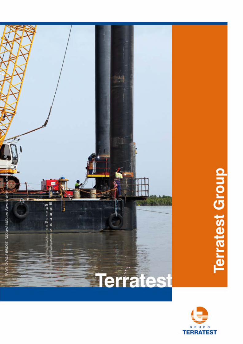
trans gambia bridge. 1200 and 1500 mm diameter … · keys (abb seal) designed by ... pre-cast...
TRANSCRIPT
TRAN
S G
AMB
IA B
RID
GE.
120
0 an
d 15
00 m
m d
iam
eter
driv
en s
teel
pile
, 60
m d
epth
2
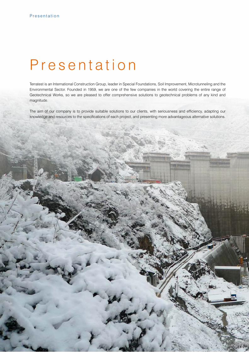
P r e s e n t a t i o n
Terratest is an International Construction Group, leader in Special Foundations, Soil Improvement, Microtunneling and the Environmental Sector. Founded in 1959, we are one of the few companies in the world covering the entire range of Geotechnical Works, so we are pleased to offer comprehensive solutions to geotechnical problems of any kind and magnitude.
The aim of our company is to provide suitable solutions to our clients, with seriousness and efficiency, adapting our knowledge and resources to the specifications of each project, and presenting more advantageous alternative solutions.
P r e s e n t a t i o n
3
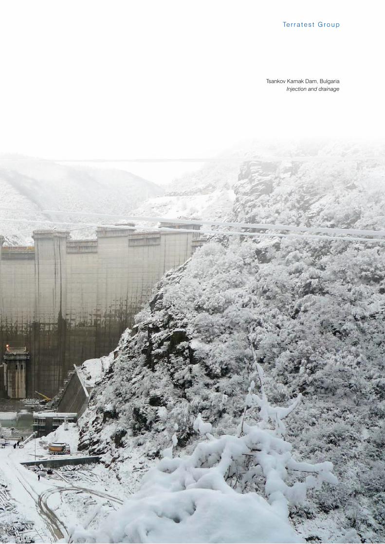
Te r r a t e s t G r o u p
Tsankov Kamak Dam, BulgariaInjection and drainage
4
Te r r a t e s t N e t w o r k
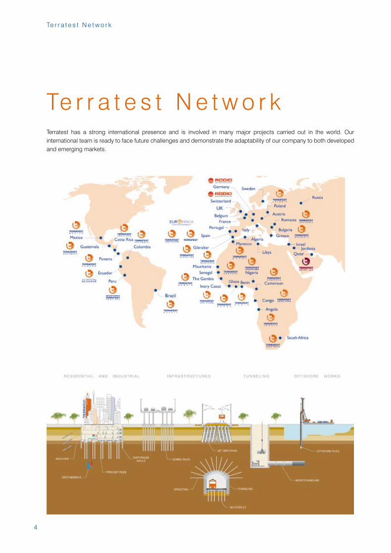
Te r r a t e s t N e t w o r kTerratest has a strong international presence and is involved in many major projects carried out in the world. Our international team is ready to face future challenges and demonstrate the adaptability of our company to both developed and emerging markets.
5
Te r r a t e s t G r o u p
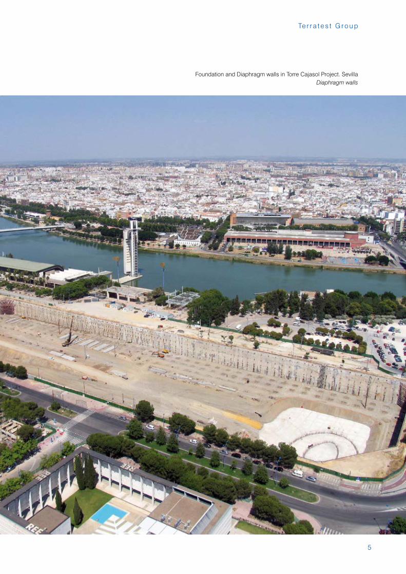
Foundation and Diaphragm walls in Torre Cajasol Project. SevillaDiaphragm walls

6
A c t i v i t i e s
A c t i v i t i e s
Bored piles
Piles Excavation Support
Offshore Piles
Micropiles
Precast Piles
CFA
Diaphragm walls
Sheetpiles / Metallic Bracing
Ground Anchors
Soil Nailing
Trench Cutter
Stone Columns
Ground Improvement
Underpinning
Compaction Grouting
Compensation Grouting
Jet Grouting
7
Te r r a t e s t G r o u p
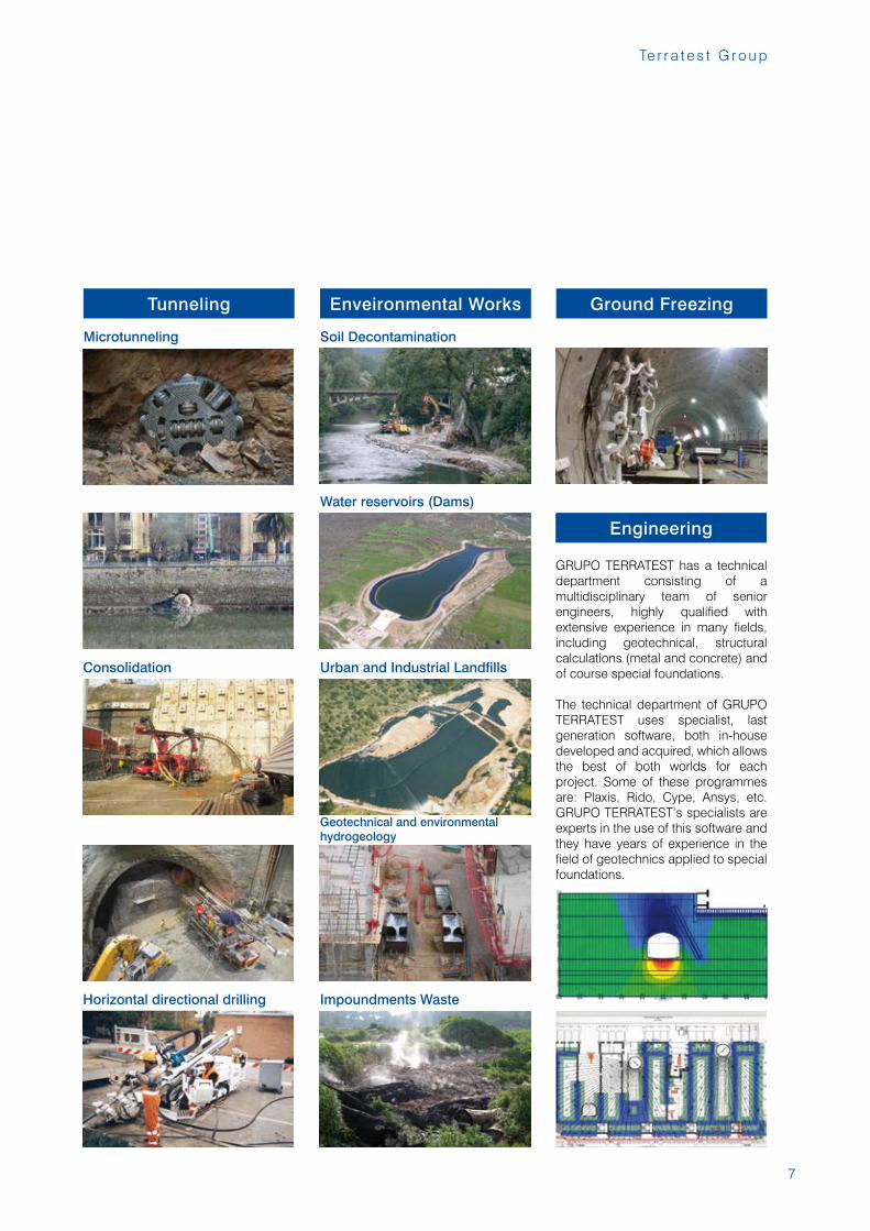
Soil Decontamination
Enveironmental Works
Urban and Industrial Landfills
Microtunneling
Tunneling
Horizontal directional drilling
Consolidation
Water reservoirs (Dams)
Geotechnical and environmental hydrogeology
GRUPO TERRATEST has a technical department consisting of a multidisciplinary team of senior engineers, highly qualified with extensive experience in many fields, including geotechnical, structural calculations (metal and concrete) and of course special foundations.
The technical department of GRUPO TERRATEST uses specialist, last generation software, both in-house developed and acquired, which allows the best of both worlds for each project. Some of these programmes are: Plaxis, Rido, Cype, Ansys, etc. GRUPO TERRATEST’s specialists are experts in the use of this software and they have years of experience in the field of geotechnics applied to special foundations.
Engineering
Impoundments Waste
Ground Freezing
8
A c t i v i t i e s
PILES
BORED PILES
Concept and characteristicsExtraction piles, bore-cast and concreted «in situ», constitute one of the classic foundation systems for problems arising from the land’s support capacity or from the need to carry heavy loads transmitted by the structure to which the foundations are destined.
The pile diameters that can be achieved have no limitation, but generally vary progressively between 400 and 2500 mm. The depths that can be reached exceed 60 m.
ProcedureThere are basically three phases in the procedure for a pile bored and concreted «in situ»:a) The boreb) Installation of reinforcementc) ConcretingThe characteristics of the land (stratigraphy, water level, etc.) condition the bore type and system: dry rotation, rotation with recoverable casing,rotation with muds or polymersic mixtures and, finally, with and recoverable casing chissel&grab.
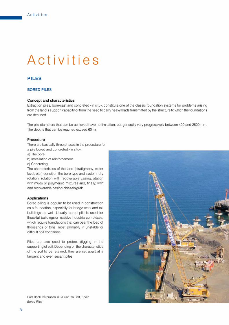
ApplicationsBored piling is popular to be used in construction as a foundation, especially for bridge work and tall buildings as well. Usually bored pile is used for those tall buildings or massive industrial complexes, which require foundations that can bear the load of thousands of tons, most probably in unstable or difficult soil conditions.
Piles are also used to protect digging in the supporting of soil. Depending on the characteristics of the soil to be retained, they are set apart at a tangent and even secant piles.
A c t i v i t i e s
East dock restoration in La Coruña Port, Spain
Bored Piles
9
Te r r a t e s t G r o u p
CFA
Concept and characteristicsThe continuous auger bored piles belong to the category of bored piles with partial soil removal. Drilling is performed by means of a hollow, continuous auger.
This technique allows the production of piles with diameters varying from 300 to 1000 mm, for a maximum depth of 30 meters.
ProcedureA hollow auger is inserted into the ground once the necessary depth has been worked out, and then concrete is pumped down the hollow stem. At the same time, the hollow auger is withdrawn and, in order to reinforce the piling, a reinforced cage is used.
It is possible to monitor the entire installation process of the piles. A flow meter provides accurate data that is then recorded and can be analyzed. Information that is collected includes penetration/uplift per revolution, auger depth and injection of pressure at the head of the auger.
ApplicationsOne of the benefits of CFA piles is that there is no casing involved and so there is minimal disruption associated with using them. They also help to keep vibrations to a minimum and can be used on large projects, making them a good piling solution for a range of situations.
CFA piles are a type of piling that is especially good for use on building sites where there is a need to keep noise to a minimum.
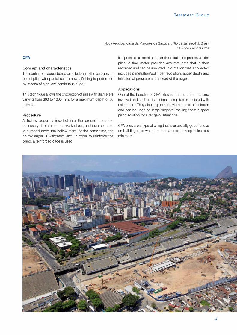
Nova Arquibancada da Marquês de Sapucaí . Rio de Janeiro/RJ. BrasilCFA and Precast Piles
10
A c t i v i t i e s
PRECAST PILES
ProcedureThe piles are driven with modern, free-fall equipment, using a hammer of between 5 and 9 tons raised either by a simple cable system, or the most advanced hydraulic drive methods with high performance and controls. This equipment is completely autonomous (requiring no auxiliary components) and mounted on crawler-cranes for easy movement.
Precast square elements are joint together with special keys (ABB seal) designed by Terratest technical department. The ABB seal is the element allowing the union of different pile sections, to reach the necessary depth. These seals are made with high-quality materials, and calculated to bear greater stresses even that the pile’s standard section, as demonstrated in bending, compression and traction trials.
Applications
Precast piles ApplicattionsPrecast piles are especially utilised for their low cost advantages, for sites in remote areas and for foundations with contained vertical loads applied.
Precast prestressed piles ApplicattionsBecause of the initial prestress force, TERRA’s precast prestressed piles are particularly indicated for the absorption of traction and bending strains, and horizontal thrust, giving foundations which are more economical than other designs.
The following may be highlighted, among other applications:- Structures (bridges and viaducts).- Tall buildings or those situated in earthquake zones.- Structures and buildings where the ground floor or basement levels are below the water table.- Contention of walls, basements, etc.- Industrial buildings with significant horizontal or bending stresses.
Structure LAV Levante, Section Villena Sax, Alicante, SpainPrecast Piles
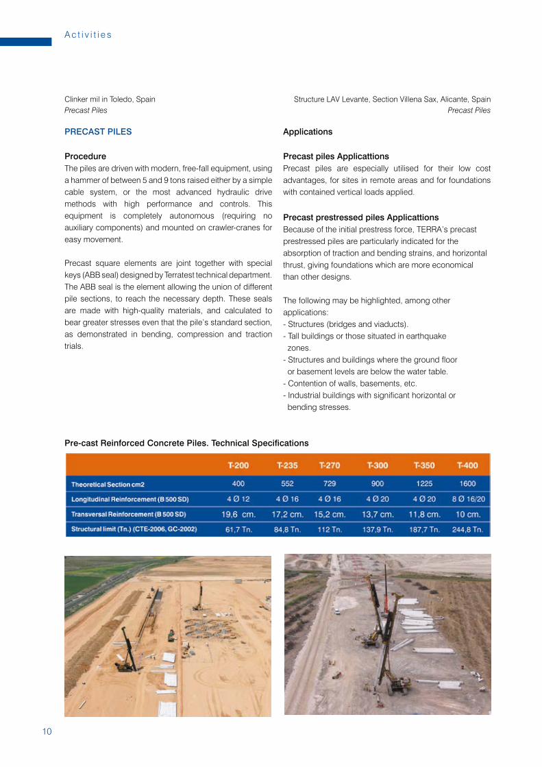
Pre-cast Reinforced Concrete Piles. Technical Specifications
Clinker mil in Toledo, SpainPrecast Piles
11
Te r r a t e s t G r o u p
MICROPILES
Concept and characteristicsMicropiles are small diameter cylindrical holes (between 114 and 400mm), into which a tubular metal frame is introduced, normally with a high elasticity limit (also bar reinforcement is used). It is joined to the ground by the means of a pressure injection of cement grout or mortar.
Procedure1. BORINGThe technique used to bore for a micropile depends basically on the type of land involved. While there are several boring procedures, the following are the most used:- OD.- ODEX.- Rotation.- Hammer rotopercussion at the head.Although it is not necessary in some cases to protect the bore against internal land collapse, it is usual to use recoverable casing, and sweeps with water and compressed air. If the land is not stable for boring, it may be necessary to use waste tubing, which can substitute for or complement the reinforcing required. The bore is washed with water and/or pressurised air. If the reinforcement is tubular, which is the most-used, it goes into the bore once the washing is finished. Bar reinforcing is introduced once the bore is grouted.
2. GROUTINGGrouting is done using the reverse circulation pumping technique for the cement or mortar.
For tubular reinforcement, pumping is done through the tube, to the bottom of the bore, then up through the annular space formed between it and the land, shifting the bore detritus with it. If the tubing is itself the reinforcement, grouting is done following bore cleaning. If a bar, it is grouted following washing, and the bar is introduced immediately afterward.
ApplicationsThe applications are many, most particularly in all types of work involving reduced space or where large machines are not possible because of their excessive weight:- Rehabilitation of all types of buildings.- Underpinning.- Foundation reinforcement in building extensions.- Deep foundations on small plots.- Support for existing foundations for basement excavation.- Slurry walls in reduced spaces.- Slope stabilisation on roads.- Fore-poling for tunnel openings.- Deep foundations on land not suitable for conventional piling.
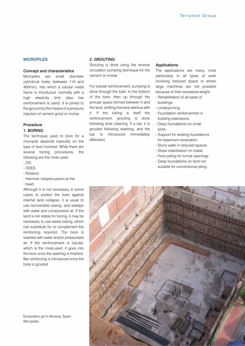
Excavation pit in Almeria, SpainMicropiles
12
A c t i v i t i e s
EXCAVATION SUPPORT
DIAPHRAGM WALLS
Concept and characteristicsContinuous reinforced concrete core walls are vertical walls made in spans of up to 7 metres in length and thicknesses between 0.40 and 1.50 metres, and depths of up to 70 m, and offer a solution to excavation difficulties in urban areas or around the water table level.
ProcedureTo install diaphragm walls in the ground, mechanically-driven grab buckets are used with weight ratings of between 5 and 23 Tons and grab openings of between 2.60 and 4.20 metres. The grab will start the excavation to the projected depth, normally with the help of bentonite slurries. These liquids, of variable density (and whose principle component is bentonite) allow the excavation to be completed cleanly and do not trigger landslides from the surrounding walls. The bentonite can be introduced into the excavation cavity by pumps from storage tanks.
Once the foundation trench is excavated (the name given to the hole from the depth and maximum aperture of the hydraulic grab, cable or rotary to the hole to be filled with thixotropic cement) the steel support indicated in the framework and cutting plans is introduced, then the concrete is poured through an elephant trunk system, consisting of a bell type tongue and grove system (tremie pipe). With the help of excavation or other auxiliary equipment the framework is introduced and concreted whilst the excavation begins on the next trench. These steps are repeated successively until
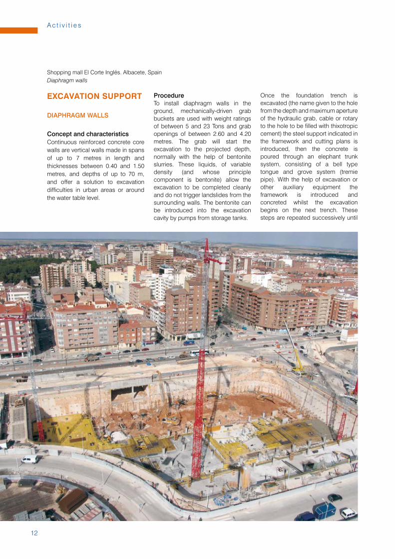
Shopping mall El Corte Inglés. Albacete, SpainDiaphragm walls
13
Te r r a t e s t G r o u p
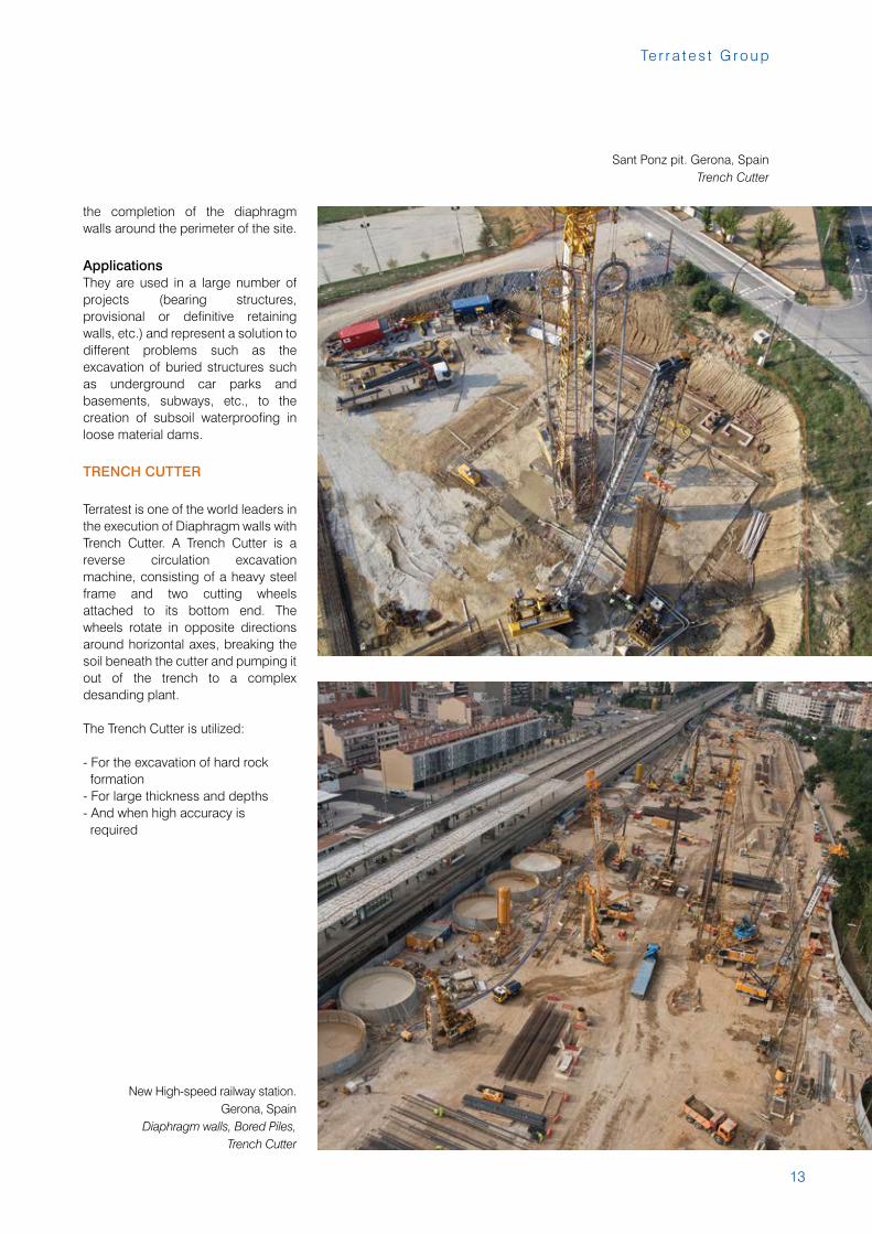
Sant Ponz pit. Gerona, SpainTrench Cutter
the completion of the diaphragm walls around the perimeter of the site.
ApplicationsThey are used in a large number of projects (bearing structures, provisional or definitive retaining walls, etc.) and represent a solution to different problems such as the excavation of buried structures such as underground car parks and basements, subways, etc., to the creation of subsoil waterproofing in loose material dams.
TRENCH CUTTER
Terratest is one of the world leaders in the execution of Diaphragm walls with Trench Cutter. A Trench Cutter is a reverse circulation excavation machine, consisting of a heavy steel frame and two cutting wheels attached to its bottom end. The wheels rotate in opposite directions around horizontal axes, breaking the soil beneath the cutter and pumping it out of the trench to a complex desanding plant.
The Trench Cutter is utilized:
- For the excavation of hard rock formation- For large thickness and depths- And when high accuracy is required
New High-speed railway station. Gerona, Spain
Diaphragm walls, Bored Piles, Trench Cutter
14
A c t i v i t i e s
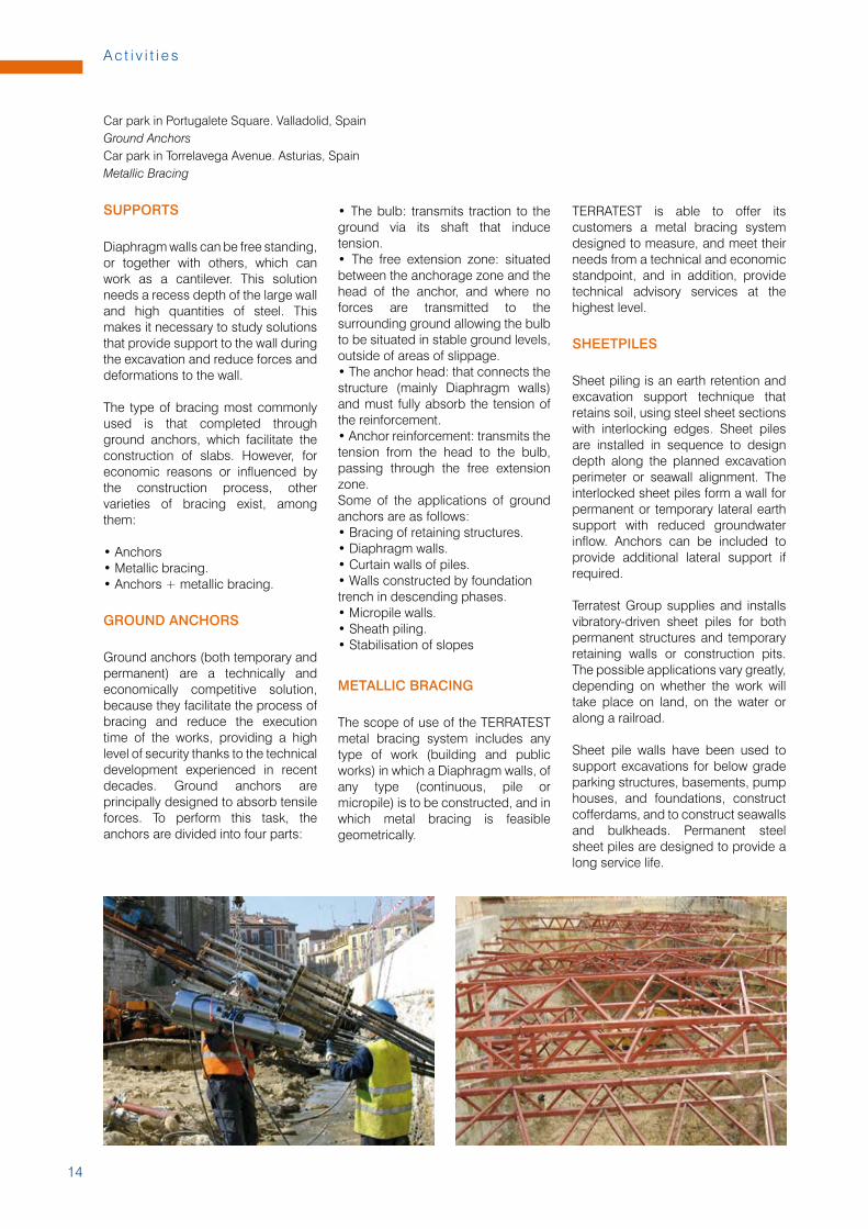
Car park in Portugalete Square. Valladolid, SpainGround AnchorsCar park in Torrelavega Avenue. Asturias, SpainMetallic Bracing
SUPPORTS
Diaphragm walls can be free standing, or together with others, which can work as a cantilever. This solution needs a recess depth of the large wall and high quantities of steel. This makes it necessary to study solutions that provide support to the wall during the excavation and reduce forces and deformations to the wall.
The type of bracing most commonly used is that completed through ground anchors, which facilitate the construction of slabs. However, for economic reasons or influenced by the construction process, other varieties of bracing exist, among them:
• Anchors• Metallic bracing.• Anchors + metallic bracing.
GROUND ANCHORS
Ground anchors (both temporary and permanent) are a technically and economically competitive solution, because they facilitate the process of bracing and reduce the execution time of the works, providing a high level of security thanks to the technical development experienced in recent decades. Ground anchors are principally designed to absorb tensile forces. To perform this task, the anchors are divided into four parts:
• The bulb: transmits traction to the ground via its shaft that induce tension.• The free extension zone: situated between the anchorage zone and the head of the anchor, and where no forces are transmitted to the surrounding ground allowing the bulb to be situated in stable ground levels, outside of areas of slippage.• The anchor head: that connects the structure (mainly Diaphragm walls) and must fully absorb the tension of the reinforcement.• Anchor reinforcement: transmits the tension from the head to the bulb, passing through the free extension zone.Some of the applications of ground anchors are as follows: • Bracing of retaining structures.• Diaphragm walls.• Curtain walls of piles.• Walls constructed by foundationtrench in descending phases.• Micropile walls.• Sheath piling.• Stabilisation of slopes
METALLIC BRACING
The scope of use of the TERRATEST metal bracing system includes any type of work (building and public works) in which a Diaphragm walls, of any type (continuous, pile or micropile) is to be constructed, and in which metal bracing is feasible geometrically.
TERRATEST is able to offer its customers a metal bracing system designed to measure, and meet their needs from a technical and economic standpoint, and in addition, provide technical advisory services at the highest level.
SHEETPILES
Sheet piling is an earth retention and excavation support technique that retains soil, using steel sheet sections with interlocking edges. Sheet piles are installed in sequence to design depth along the planned excavation perimeter or seawall alignment. The interlocked sheet piles form a wall for permanent or temporary lateral earth support with reduced groundwater inflow. Anchors can be included to provide additional lateral support if required.
Terratest Group supplies and installs vibratory-driven sheet piles for both permanent structures and temporary retaining walls or construction pits. The possible applications vary greatly, depending on whether the work will take place on land, on the water or along a railroad.
Sheet pile walls have been used to support excavations for below grade parking structures, basements, pump houses, and foundations, construct cofferdams, and to construct seawalls and bulkheads. Permanent steel sheet piles are designed to provide a long service life.
15
Te r r a t e s t G r o u p
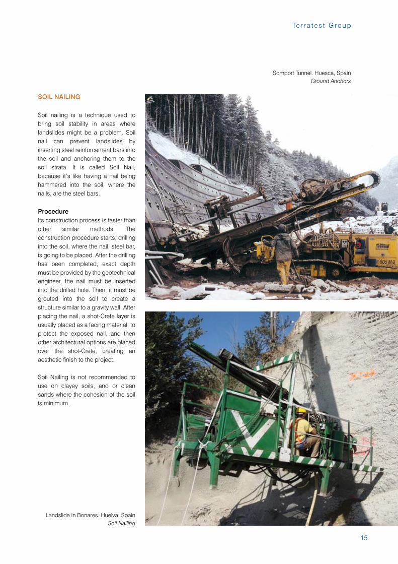
Somport Tunnel. Huesca, SpainGround Anchors
Landslide in Bonares. Huelva, SpainSoil Nailing
SOIL NAILING
Soil nailing is a technique used to bring soil stability in areas where landslides might be a problem. Soil nail can prevent landslides by inserting steel reinforcement bars into the soil and anchoring them to the soil strata. It is called Soil Nail, because it’s like having a nail being hammered into the soil, where the nails, are the steel bars.
ProcedureIts construction process is faster than other similar methods. The construction procedure starts, drilling into the soil, where the nail, steel bar, is going to be placed. After the drilling has been completed, exact depth must be provided by the geotechnical engineer, the nail must be inserted into the drilled hole. Then, it must be grouted into the soil to create a structure similar to a gravity wall. After placing the nail, a shot-Crete layer is usually placed as a facing material, to protect the exposed nail, and then other architectural options are placed over the shot-Crete, creating an aesthetic finish to the project.
Soil Nailing is not recommended to use on clayey soils, and or clean sands where the cohesion of the soil is minimum.
16
A c t i v i t i e s
GROUND IMPROVEMENT
STONE COLUMNS
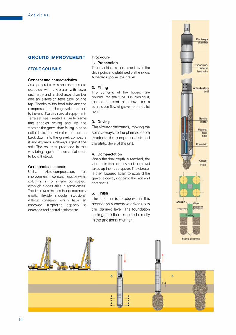
Concept and characteristicsAs a general rule, stone columns are executed with a vibrator with lower discharge and a discharge chamber and an extension feed tube on the top. Thanks to the feed tube and the compressed air, the gravel is pushed to the end. For this special equipment, Terratest has created a guide frame that enables driving and lifts the vibrator, the gravel then falling into the outlet hole. The vibrator then drops back down into the gravel, compacts it and expands sideways against the soil. The columns produced in this way bring together the essential loads to be withstood.
Geotechnical aspectsUnlike vibro-compactation, an improvement in compactness between columns is not initially considered, although it does arise in some cases. The improvement lies in the extremely elastic flexible module inclusions, without cohesion, which have an improved supporting capacity to decrease and control settlements.
Procedure1. PreparationThe machine is positioned over the drive point and stabilised on the skids. A loader supplies the gravel.
2. FillingThe contents of the hopper are poured into the tube. On closing it, the compressed air allows for a continuous flow of gravel to the outlet hole.
3. DrivingThe vibrator descends, moving the soil sideways, to the planned depth thanks to the compressed air and the static drive of the unit.
4. CompactationWhen the final depth is reached, the vibrator is lifted slightly and the gravel takes up the freed space. The vibrator is then lowered again to expand the gravel sideways against the soil and compact it.
5. FinishThe column is produced in this manner on successive drives up to the planned level. The foundation footings are then executed directly in the traditional manner.
17
Te r r a t e s t G r o u p
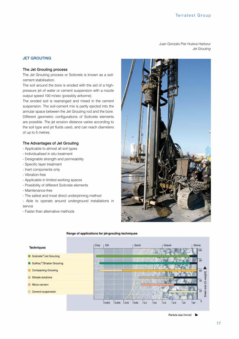
JET GROUTING
The Jet Grouting processThe Jet Grouting process or Soilcrete is known as a soil-cement stabilisation.The soil around the bore is eroded with the aid of a high-pressure jet of water or cement suspension with a nozzle output speed 100 m/sec (possibly airborne).The eroded soil is rearranged and mixed in the cement suspension. The soil-cement mix is partly ejected into the annular space between the Jet Grouting rod and the bore.Different geometric configurations of Soilcrete elements are possible. The jet erosion distance varies according to the soil type and jet fluids used, and can reach diameters of up to 5 metres.
The Advantages of Jet Grouting- Applicable to almost all soil types- Individualised in situ treatment- Designable strength and permeability- Specific layer treatment- Inert components only- Vibration-free- Applicable in limited working spaces- Possibility of different Soilcrete elements- Maintenance-free- The safest and most direct underpinning method- Able to operate around underground installations in servce- Faster than alternative methods
Juan Gonzalo Pier Huelva HarbourJet Grouting
18
A c t i v i t i e s
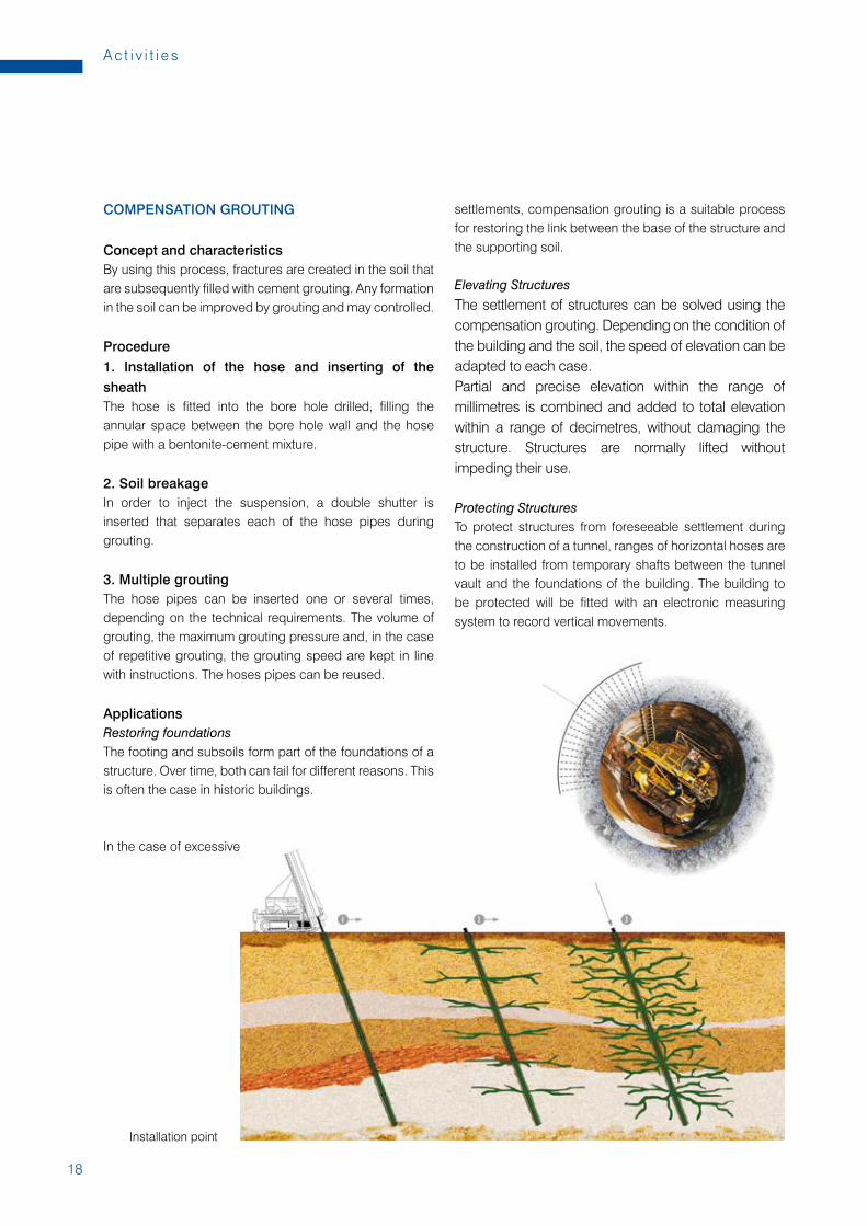
COMPENSATION GROUTING
Concept and characteristicsBy using this process, fractures are created in the soil that are subsequently filled with cement grouting. Any formation in the soil can be improved by grouting and may controlled.
Procedure1. Installation of the hose and inserting of the sheathThe hose is fitted into the bore hole drilled, filling the annular space between the bore hole wall and the hose pipe with a bentonite-cement mixture.
2. Soil breakageIn order to inject the suspension, a double shutter is inserted that separates each of the hose pipes during grouting.
3. Multiple groutingThe hose pipes can be inserted one or several times, depending on the technical requirements. The volume of grouting, the maximum grouting pressure and, in the case of repetitive grouting, the grouting speed are kept in line with instructions. The hoses pipes can be reused.
ApplicationsRestoring foundationsThe footing and subsoils form part of the foundations of a structure. Over time, both can fail for different reasons. This is often the case in historic buildings.
In the case of excessive
settlements, compensation grouting is a suitable process for restoring the link between the base of the structure and the supporting soil.
Elevating StructuresThe settlement of structures can be solved using the compensation grouting. Depending on the condition of the building and the soil, the speed of elevation can be adapted to each case.Partial and precise elevation within the range of millimetres is combined and added to total elevation within a range of decimetres, without damaging the structure. Structures are normally lifted without impeding their use.
Protecting StructuresTo protect structures from foreseeable settlement during the construction of a tunnel, ranges of horizontal hoses are to be installed from temporary shafts between the tunnel vault and the foundations of the building. The building to be protected will be fitted with an electronic measuring system to record vertical movements.
Installation point
19
Te r r a t e s t G r o u p
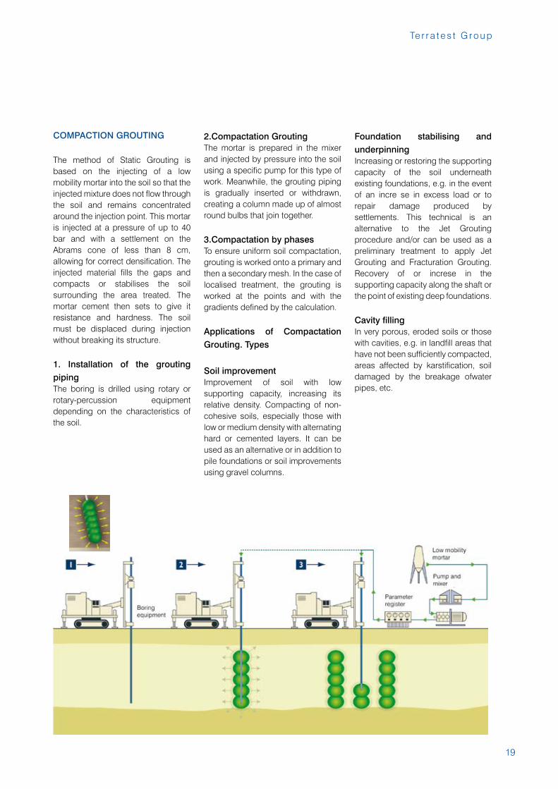
COMPACTION GROUTING
The method of Static Grouting is based on the injecting of a low mobility mortar into the soil so that the injected mixture does not flow through the soil and remains concentrated around the injection point. This mortar is injected at a pressure of up to 40 bar and with a settlement on the Abrams cone of less than 8 cm, allowing for correct densification. The injected material fills the gaps and compacts or stabilises the soil surrounding the area treated. The mortar cement then sets to give it resistance and hardness. The soil must be displaced during injection without breaking its structure.
1. Installation of the grouting pipingThe boring is drilled using rotary or rotary-percussion equipment depending on the characteristics of the soil.
2.Compactation GroutingThe mortar is prepared in the mixer and injected by pressure into the soil using a specific pump for this type of work. Meanwhile, the grouting piping is gradually inserted or withdrawn, creating a column made up of almost round bulbs that join together.
3.Compactation by phasesTo ensure uniform soil compactation, grouting is worked onto a primary and then a secondary mesh. In the case of localised treatment, the grouting is worked at the points and with the gradients defined by the calculation.
Applications of Compactation Grouting. Types
Soil improvement Improvement of soil with low supporting capacity, increasing its relative density. Compacting of non-cohesive soils, especially those with low or medium density with alternating hard or cemented layers. It can be used as an alternative or in addition to pile foundations or soil improvements using gravel columns.
Foundation stabilising and underpinningIncreasing or restoring the supporting capacity of the soil underneath existing foundations, e.g. in the event of an incre se in excess load or to repair damage produced by settlements. This technical is an alternative to the Jet Grouting procedure and/or can be used as a preliminary treatment to apply Jet Grouting and Fracturation Grouting. Recovery of or increse in the supporting capacity along the shaft or the point of existing deep foundations.
Cavity fillingIn very porous, eroded soils or those with cavities, e.g. in landfill areas that have not been sufficiently compacted, areas affected by karstification, soil damaged by the breakage ofwater pipes, etc.
20
A c t i v i t i e s
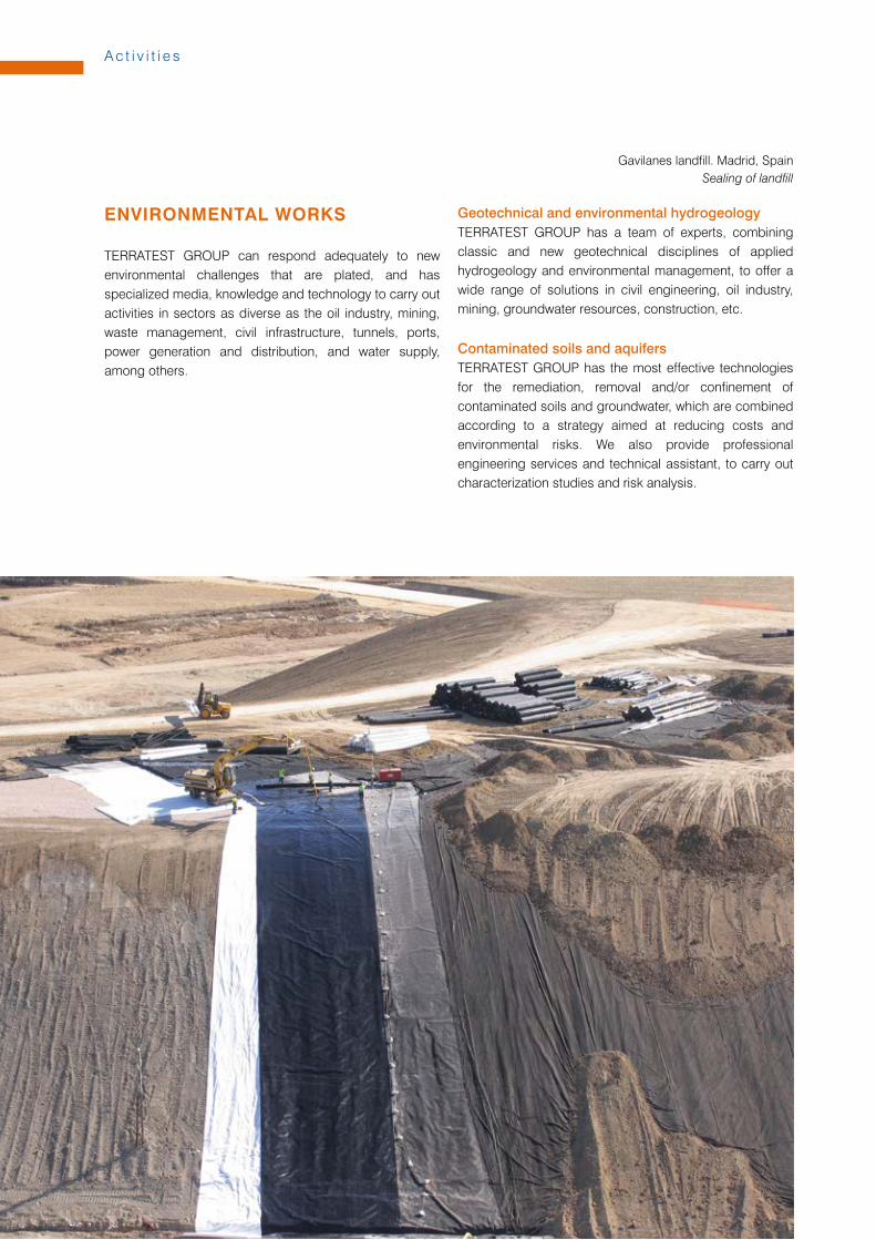
ENVIRONMENTAL WORKS
TERRATEST GROUP can respond adequately to new environmental challenges that are plated, and has specialized media, knowledge and technology to carry out activities in sectors as diverse as the oil industry, mining, waste management, civil infrastructure, tunnels, ports, power generation and distribution, and water supply, among others.
Geotechnical and environmental hydrogeologyTERRATEST GROUP has a team of experts, combining classic and new geotechnical disciplines of applied hydrogeology and environmental management, to offer a wide range of solutions in civil engineering, oil industry, mining, groundwater resources, construction, etc.
Contaminated soils and aquifersTERRATEST GROUP has the most effective technologies for the remediation, removal and/or confinement of contaminated soils and groundwater, which are combined according to a strategy aimed at reducing costs and environmental risks. We also provide professional engineering services and technical assistant, to carry out characterization studies and risk analysis.
Gavilanes landfill. Madrid, SpainSealing of landfill
21
Te r r a t e s t G r o u p
Urban and industrial landfillsTERRATEST GROUP offers the best available techniques for performing the work of waterproofing of landfills for municipal and industrial waste. Also we provide research services as location, environmental impact, design and drafting of projects, and control and environmental monitoring.
Sealing and degassing of landfillsThe closing and sealing of landfills is aimed at reducing the environmental impact of final disposal of waste on the environment, ensuing isolation conditions in time to prevent contamination of soil and ground water, and the emission of gases and odors to the atmosphere.In the case of municipal waste landfills, are particular relevant, the actions of degassing and energetic use of biogas generated.
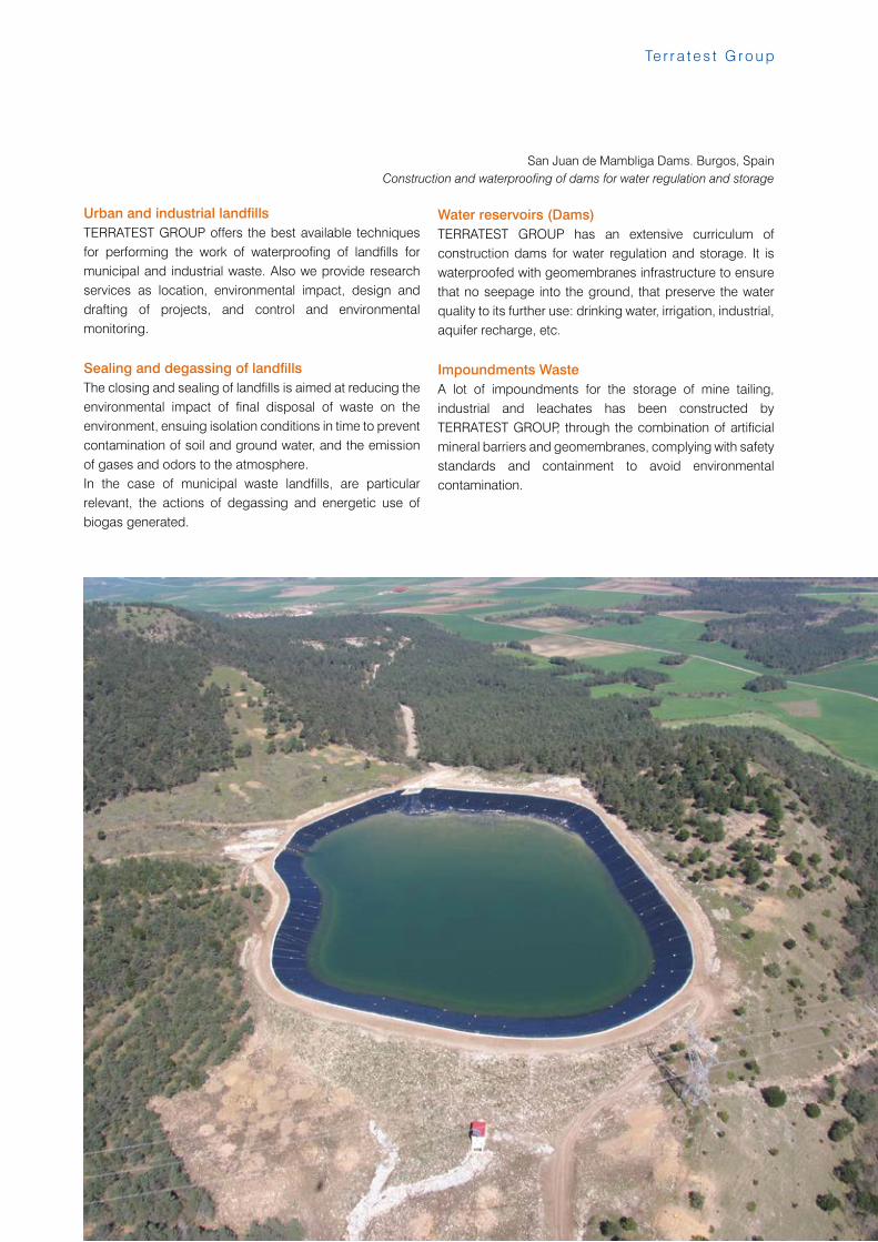
Water reservoirs (Dams)TERRATEST GROUP has an extensive curriculum of construction dams for water regulation and storage. It is waterproofed with geomembranes infrastructure to ensure that no seepage into the ground, that preserve the water quality to its further use: drinking water, irrigation, industrial, aquifer recharge, etc.
Impoundments WasteA lot of impoundments for the storage of mine tailing, industrial and leachates has been constructed by TERRATEST GROUP, through the combination of artificial mineral barriers and geomembranes, complying with safety standards and containment to avoid environmental contamination.
San Juan de Mambliga Dams. Burgos, SpainConstruction and waterproofing of dams for water regulation and storage
22
A c t i v i t i e s
TUNNELING
MICROTUNNELING
INTRODUCTION
In the field of microtunneling Terratest is one of the European leaders, throughout our owned company Eurohinca, providing its own Tunnel Boring Machines and a wide experience in all kind of soil conditions and applications.T.B.M. is the abbrevation of Tunnel Boring Machine and his definition is equipment capable of digging tunnels to complete section. To restrict a bit this definition we can be divided TBM in several classifications: - Full face support TBM: TBM able to control the pressure in the front during the excavation. This type of machines can work under cities and cross road, railways, etc.- Open shields: For stabilize grounds and without any civil construction in the surface.
Depending on the tunnel support- Segment lining: Can be use in all type of ground and with all type of TBM.- Metal roof truss: Used only in rock ground and with gripper TBM.- Pipe jacking: For tunnels with diameter smaller than 3 m.
Depending on the extraction method- EPB Shield: Extraction with endless screw conveyor. - Hidroshield: Extraction with pumps. - Rock TBM, double shield and open shields: Extraction with conveyor belt.
ADVANTAGES OF TRENCHLES TECHNOLOGY
Tunnels<>Trench- Less effect on existeng services.- Lower environmental impact.- Minimizes spoil and waste generated.- Compact instalation.
TMB<>Mining- Increased security for workers.(Works inside a shield)- Less risk of surface settlements.(Excavation Front is supported)- Higher outputs. Minor delays.- Reduced impact on ground water level.
TYPICAL APPLICATIONS
- Server and water supply networks. Collectors.- Crossings under existing services.(road, streets, railways, rivers, airport runways, golf courses, etc.)- Sea outfalls. Water release or intake.- Tunnels with tunnel boring machines.- Underground corridors.- Gas and oil pipelines. Drainage and evacuation systems.- Pipe arching for road or railway crossings.- Steel pressure pipes.- Water intake and release for fish farm or desalination plants.- Water waste pipe and intakes in reservoir dam.
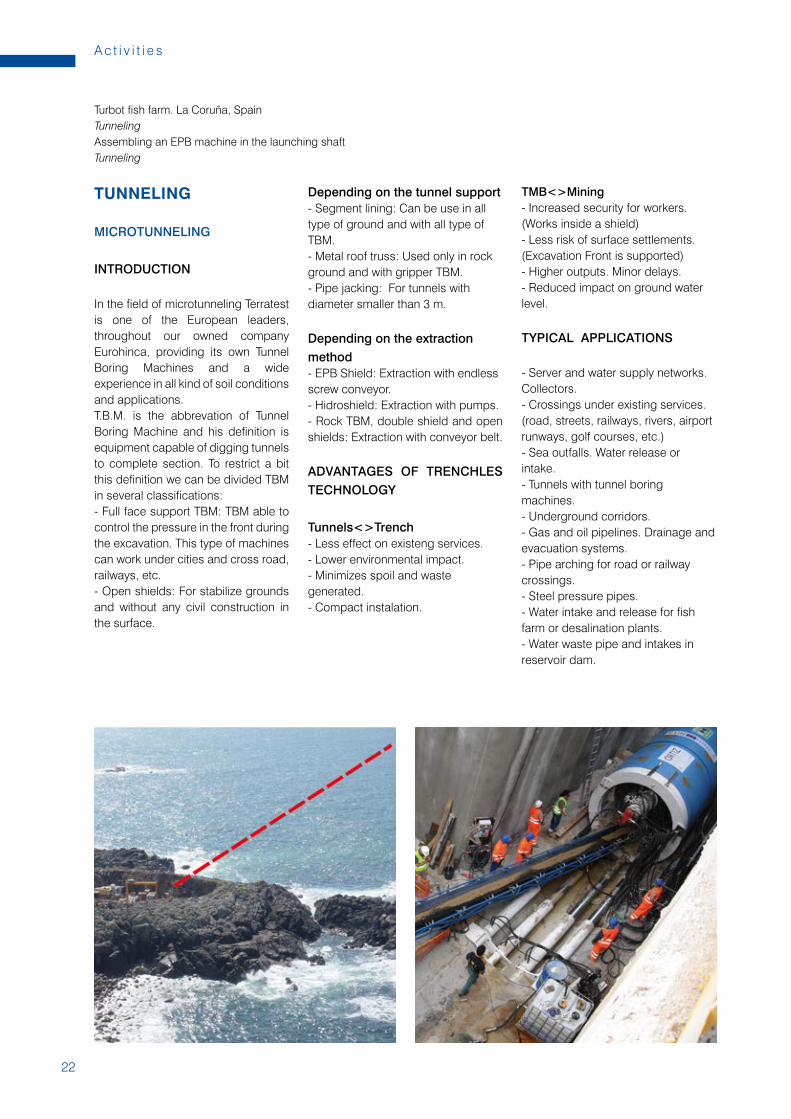
Turbot fish farm. La Coruña, SpainTunnelingAssembling an EPB machine in the launching shaftTunneling
23
Te r r a t e s t G r o u p
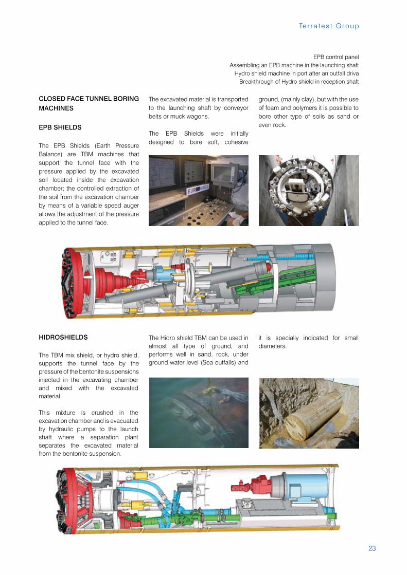
EPB control panelAssembling an EPB machine in the launching shaft
Hydro shield machine in port after an outfall drivaBreakthrough of Hydro shield in reception shaft
CLOSED FACE TUNNEL BORING MACHINES
EPB SHIELDS
The EPB Shields (Earth Pressure Balance) are TBM machines that support the tunnel face with the pressure applied by the excavated soil located inside the excavation chamber; the controlled extraction of the soil from the excavation chamber by means of a variable speed auger allows the adjustment of the pressure applied to the tunnel face.
The excavated material is transported to the launching shaft by conveyor belts or muck wagons.
The EPB Shields were initially designed to bore soft, cohesive
ground, (mainly clay), but with the use of foam and polymers it is possible to bore other type of soils as sand or even rock.
HIDROSHIELDS
The TBM mix shield, or hydro shield, supports the tunnel face by the pressure of the bentonite suspensions injected in the excavating chamber and mixed with the excavated material.
This mixture is crushed in the excavation chamber and is evacuated by hydraulic pumps to the launch shaft where a separation plant separates the excavated material from the bentonite suspension.
The Hidro shield TBM can be used in almost all type of ground, and performs well in sand, rock, under ground water level (Sea outfalls) and
it is specially indicated for small diameters.
24
A c t i v i t i e s
OPEN FACE TUNNEL BORING MACHINES
OPEN SHIELDS - ROADHEADERS OR EXCAVATION
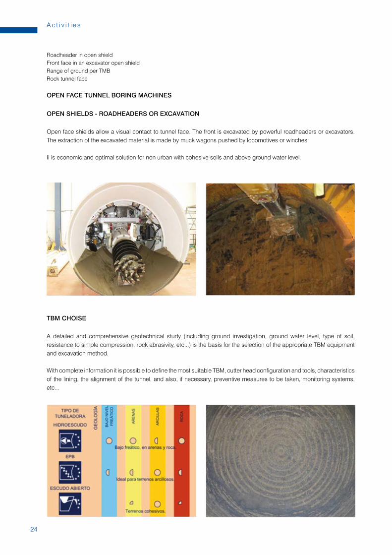
Open face shields allow a visual contact to tunnel face. The front is excavated by powerful roadheaders or excavators. The extraction of the excavated material is made by muck wagons pushed by locomotives or winches.
Ii is economic and optimal solution for non urban with cohesive soils and above ground water level.
TBM CHOISE
A detailed and comprehensive geotechnical study (including ground investigation, ground water level, type of soil, resistance to simple compression, rock abrasivity, etc...) is the basis for the selection of the appropriate TBM equipment and excavation method.
With complete information it is possible to define the most suitable TBM, cutter head configuration and tools, characteristics of the lining, the alignment of the tunnel, and also, if necessary, preventive measures to be taken, monitoring systems, etc...
Roadheader in open shieldFront face in an excavator open shieldRange of ground per TMBRock tunnel face
25
Te r r a t e s t G r o u p
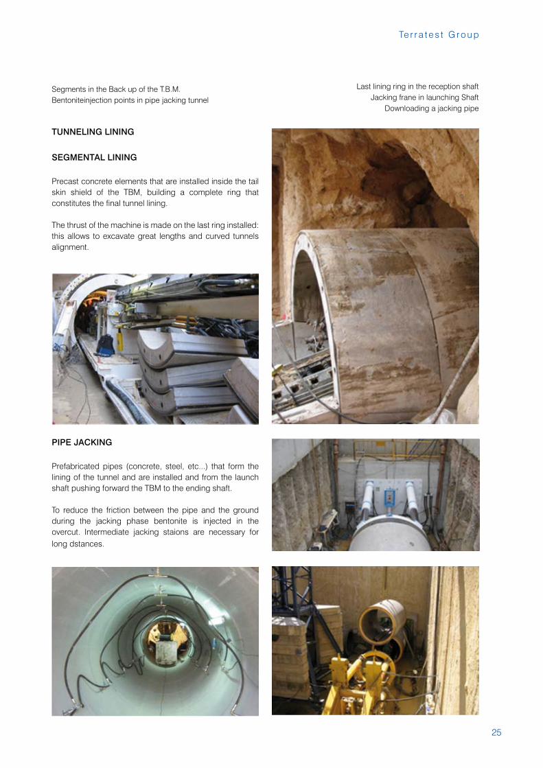
TUNNELING LINING
SEGMENTAL LINING
Precast concrete elements that are installed inside the tail skin shield of the TBM, building a complete ring that constitutes the final tunnel lining.
The thrust of the machine is made on the last ring installed: this allows to excavate great lengths and curved tunnels alignment.
PIPE JACKING
Prefabricated pipes (concrete, steel, etc...) that form the lining of the tunnel and are installed and from the launch shaft pushing forward the TBM to the ending shaft.
To reduce the friction between the pipe and the ground during the jacking phase bentonite is injected in the overcut. Intermediate jacking staions are necessary for long dstances.
Last lining ring in the reception shaftJacking frane in launching Shaft
Downloading a jacking pipe
Segments in the Back up of the T.B.M.Bentoniteinjection points in pipe jacking tunnel
26
A c t i v i t i e s
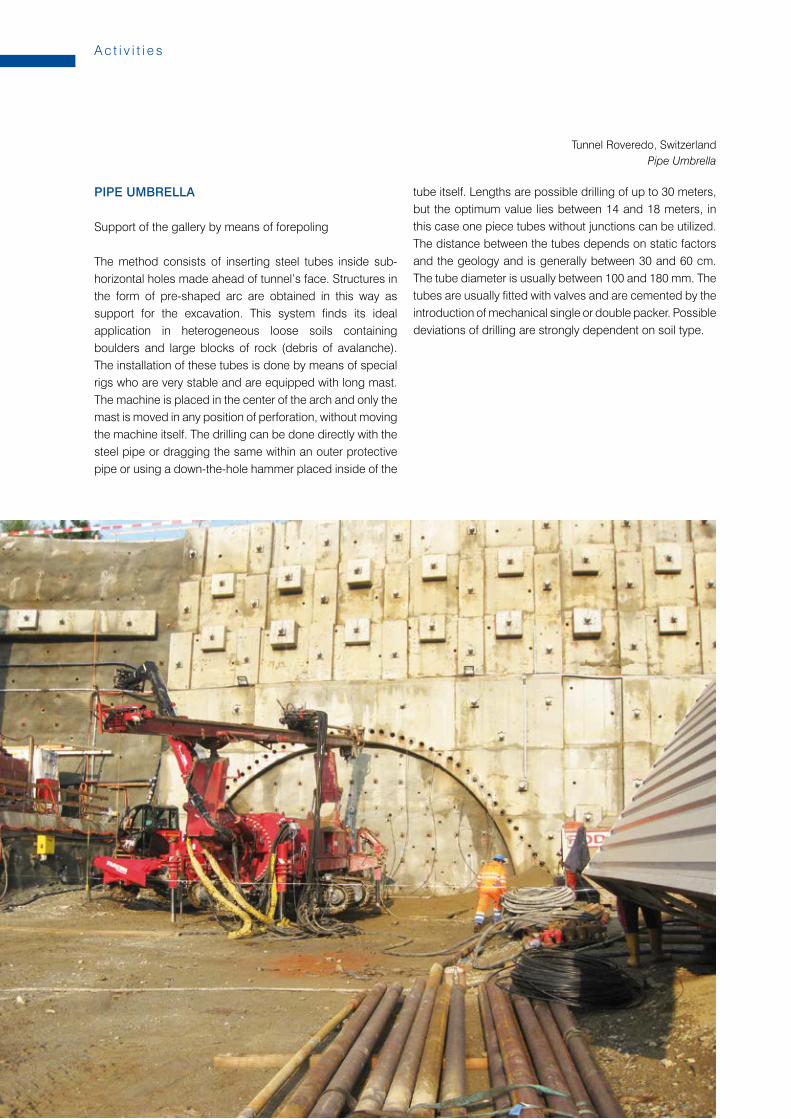
PIPE UMBRELLA
Support of the gallery by means of forepoling
The method consists of inserting steel tubes inside sub-horizontal holes made ahead of tunnel’s face. Structures in the form of pre-shaped arc are obtained in this way as support for the excavation. This system finds its ideal application in heterogeneous loose soils containing boulders and large blocks of rock (debris of avalanche). The installation of these tubes is done by means of special rigs who are very stable and are equipped with long mast. The machine is placed in the center of the arch and only the mast is moved in any position of perforation, without moving the machine itself. The drilling can be done directly with the steel pipe or dragging the same within an outer protective pipe or using a down-the-hole hammer placed inside of the
tube itself. Lengths are possible drilling of up to 30 meters, but the optimum value lies between 14 and 18 meters, in this case one piece tubes without junctions can be utilized. The distance between the tubes depends on static factors and the geology and is generally between 30 and 60 cm. The tube diameter is usually between 100 and 180 mm. The tubes are usually fitted with valves and are cemented by the introduction of mechanical single or double packer. Possible deviations of drilling are strongly dependent on soil type.
Tunnel Roveredo, SwitzerlandPipe Umbrella
27
Te r r a t e s t G r o u p
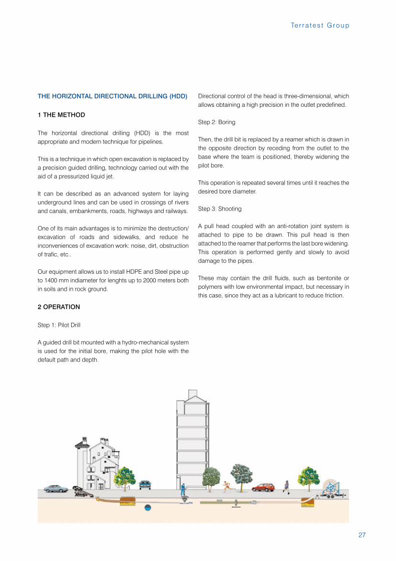
THE HORIZONTAL DIRECTIONAL DRILLING (HDD)
1 THE METHOD
The horizontal directional drilling (HDD) is the most appropriate and modern technique for pipelines.
This is a technique in which open excavation is replaced by a precision guided drilling, technology carried out with the aid of a pressurized liquid jet.
It can be described as an advanced system for laying underground lines and can be used in crossings of rivers and canals, embankments, roads, highways and railways.
One of its main advantages is to minimize the destruction/excavation of roads and sidewalks, and reduce he inconveniences of excavation work: noise, dirt, obstruction of trafic, etc..
Our equipment allows us to install HDPE and Steel pipe up to 1400 mm indiameter for lenghts up to 2000 meters both in soils and in rock ground.
2 OPERATION
Step 1: Pilot Drill
A guided drill bit mounted with a hydro-mechanical system is used for the initial bore, making the pilot hole with the default path and depth.
Directional control of the head is three-dimensional, which allows obtaining a high precision in the outlet predefined.
Step 2: Boring
Then, the drill bit is replaced by a reamer which is drawn in the opposite direction by receding from the outlet to the base where the team is positioned, thereby widening the pilot bore.
This operation is repeated several times until it reaches the desired bore diameter.
Step 3: Shooting
A pull head coupled with an anti-rotation joint system is attached to pipe to be drawn. This pull head is then attached to the reamer that performs the last bore widening. This operation is performed gently and slowly to avoid damage to the pipes.
These may contain the drill fluids, such as bentonite or polymers with low environmental impact, but necessary in this case, since they act as a lubricant to reduce friction.
28
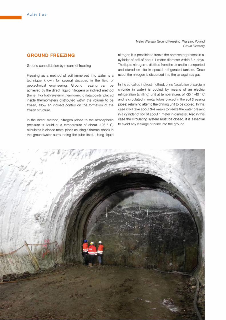
Metro Warsaw Ground Freezing, Warsaw, PolandGroun Freezing
GROUND FREEZING
Ground consolidation by means of freezing
Freezing as a method of soil immersed into water is a technique known for several decades in the field of geotechnical engineering. Ground freezing can be achieved by the direct (liquid nitrogen) or indirect method (brine). For both systems thermometric data points, placed inside thermometers distributed within the volume to be frozen, allow an indirect control on the formation of the frozen structure.
In the direct method, nitrogen (close to the atmospheric pressure is liquid at a temperature of about -196 ° C) circulates in closed metal pipes causing a thermal shock in the groundwater surrounding the tube itself. Using liquid
nitrogen it is possible to freeze the pore water present in a cylinder of soil of about 1 meter diameter within 3-4 days. The liquid nitrogen is distilled from the air and is transported and stored on site in special refrigerated tankers. Once used, the nitrogen is dispersed into the air again as gas.
In the so-called indirect method, brine (a solution of calcium chloride in water) is cooled by means of an electric refrigeration (chilling) unit at temperatures of -35 ° -40 ° C and is circulated in metal tubes placed in the soil (freezing pipes) returning after to the chilling unit to be cooled. In this case it will take about 3-4 weeks to freeze the water present in a cylinder of soil of about 1 meter in diameter. Also in this case the circulating system must be closed, it is essential to avoid any leakage of brine into the ground.
A c t i v i t i e s
29
Te r r a t e s t G r o u p
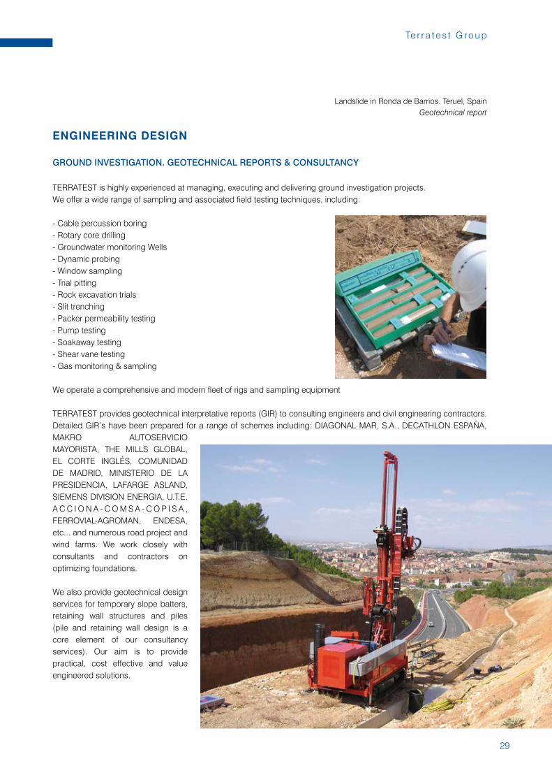
ENGINEERING DESIGN
GROUND INVESTIGATION. GEOTECHNICAL REPORTS & CONSULTANCY
TERRATEST is highly experienced at managing, executing and delivering ground investigation projects. We offer a wide range of sampling and associated field testing techniques, including:
- Cable percussion boring- Rotary core drilling- Groundwater monitoring Wells- Dynamic probing- Window sampling- Trial pitting- Rock excavation trials- Slit trenching- Packer permeability testing- Pump testing- Soakaway testing- Shear vane testing- Gas monitoring & sampling
We operate a comprehensive and modern fleet of rigs and sampling equipment
TERRATEST provides geotechnical interpretative reports (GIR) to consulting engineers and civil engineering contractors. Detailed GIR’s have been prepared for a range of schemes including: DIAGONAL MAR, S.A., DECATHLON ESPAÑA, MAKRO AUTOSERVICIO MAYORISTA, THE MILLS GLOBAL, EL CORTE INGLÉS, COMUNIDAD DE MADRID, MINISTERIO DE LA PRESIDENCIA, LAFARGE ASLAND, SIEMENS DIVISION ENERGIA, U.T.E. A C C I O N A - C O M S A - C O P I S A , FERROVIAL-AGROMAN, ENDESA, etc... and numerous road project and wind farms. We work closely with consultants and contractors on optimizing foundations.
We also provide geotechnical design services for temporary slope batters, retaining wall structures and piles (pile and retaining wall design is a core element of our consultancy services). Our aim is to provide practical, cost effective and value engineered solutions.
Landslide in Ronda de Barrios. Teruel, SpainGeotechnical report
30
A c t i v i t i e s
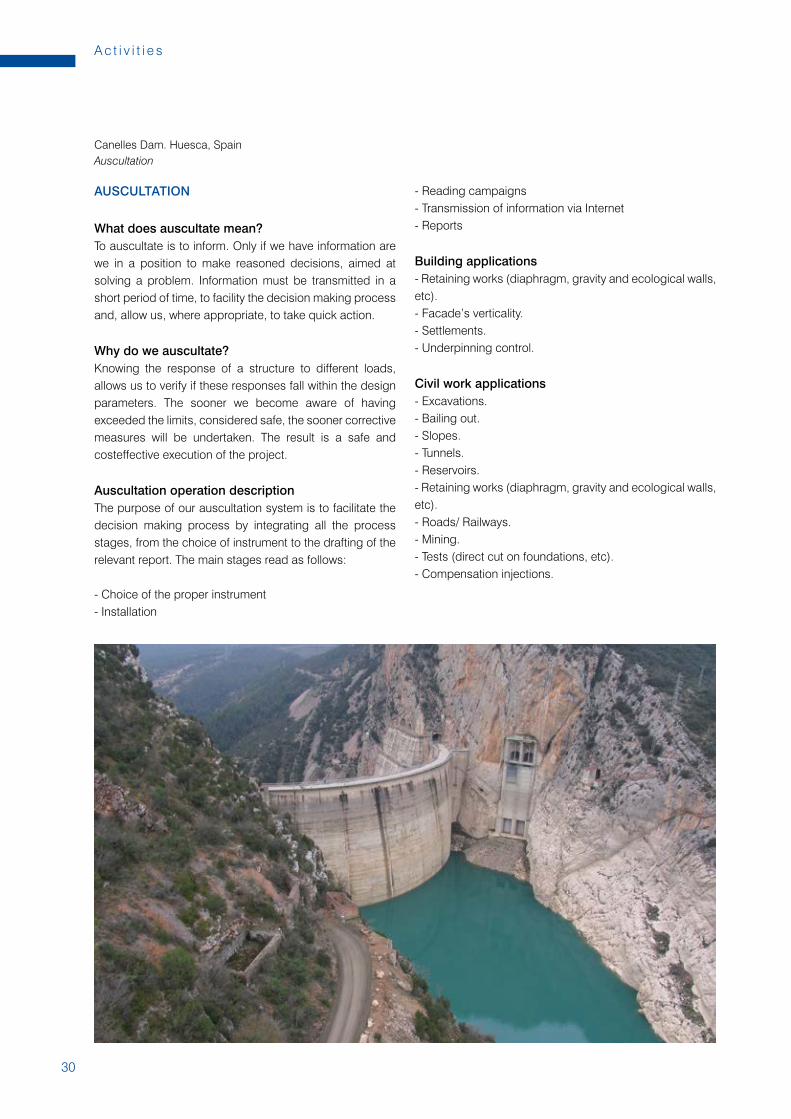
AUSCULTATION
What does auscultate mean?To auscultate is to inform. Only if we have information are we in a position to make reasoned decisions, aimed at solving a problem. Information must be transmitted in a short period of time, to facility the decision making process and, allow us, where appropriate, to take quick action.
Why do we auscultate?Knowing the response of a structure to different loads, allows us to verify if these responses fall within the design parameters. The sooner we become aware of having exceeded the limits, considered safe, the sooner corrective measures will be undertaken. The result is a safe and costeffective execution of the project.
Auscultation operation descriptionThe purpose of our auscultation system is to facilitate the decision making process by integrating all the process stages, from the choice of instrument to the drafting of the relevant report. The main stages read as follows:
- Choice of the proper instrument- Installation
- Reading campaigns- Transmission of information via Internet- Reports
Building applications- Retaining works (diaphragm, gravity and ecological walls, etc).- Facade’s verticality.- Settlements.- Underpinning control.
Civil work applications- Excavations.- Bailing out.- Slopes.- Tunnels.- Reservoirs.- Retaining works (diaphragm, gravity and ecological walls, etc).- Roads/ Railways.- Mining.- Tests (direct cut on foundations, etc).- Compensation injections.
Canelles Dam. Huesca, SpainAuscultation
31
Te r r a t e s t G r o u p
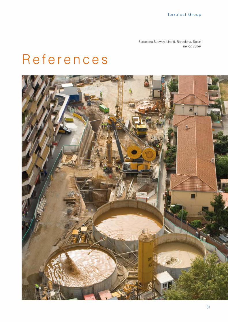
Barcelona Subway, Line 9. Barcelona, SpainTrench cutter
R e f e r e n c e s
32
R e f e r e n c e s
33
Te r r a t e s t G r o u p
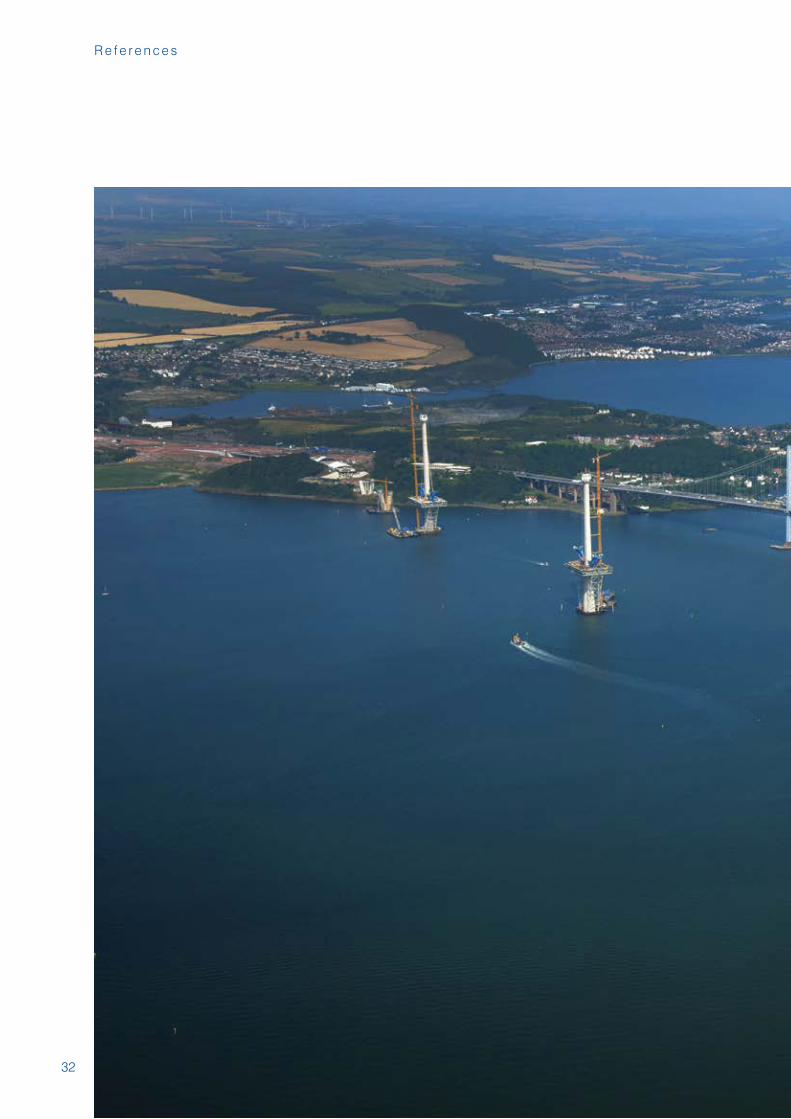
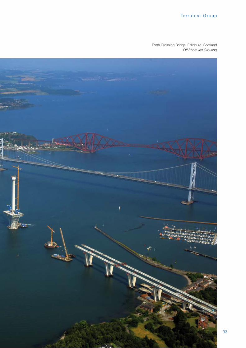
Forth Crossing Bridge. Edinburg, ScotlandOff Shore Jet Grouting
34
R e f e r e n c e s
35
Te r r a t e s t G r o u p
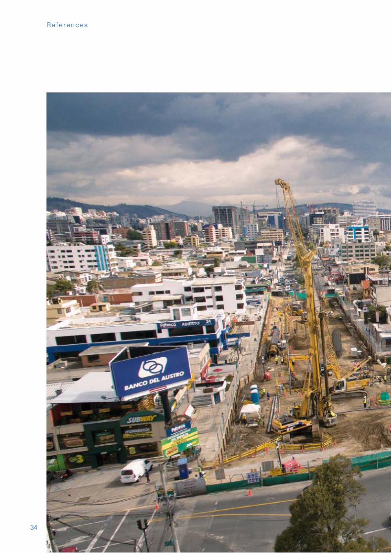
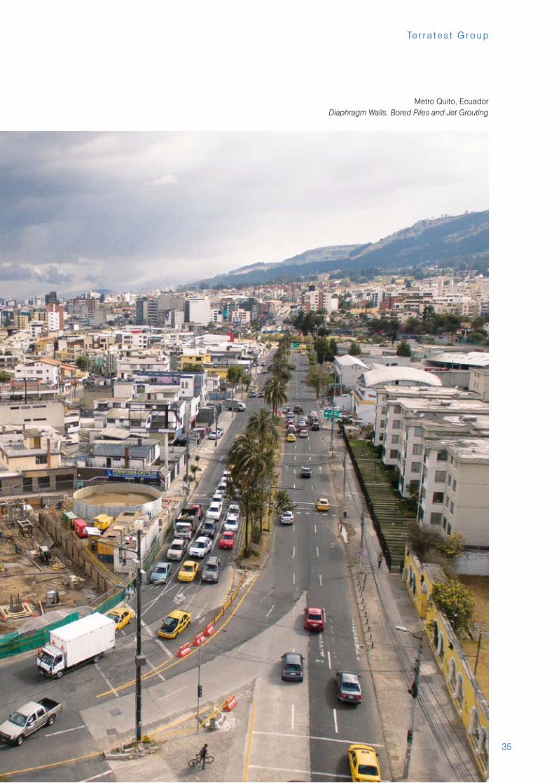
Metro Quito, EcuadorDiaphragm Walls, Bored Piles and Jet Grouting
36
R e f e r e n c e s
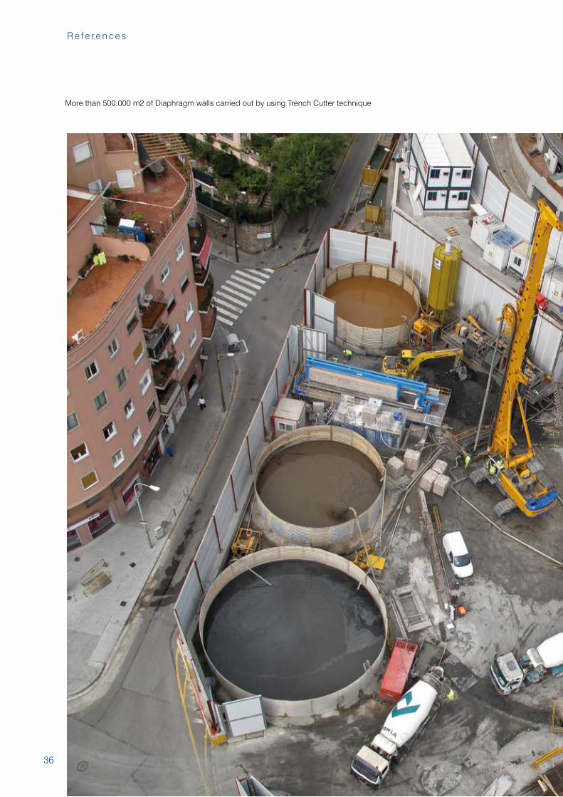
More than 500.000 m2 of Diaphragm walls carried out by using Trench Cutter technique
37
Te r r a t e s t G r o u p
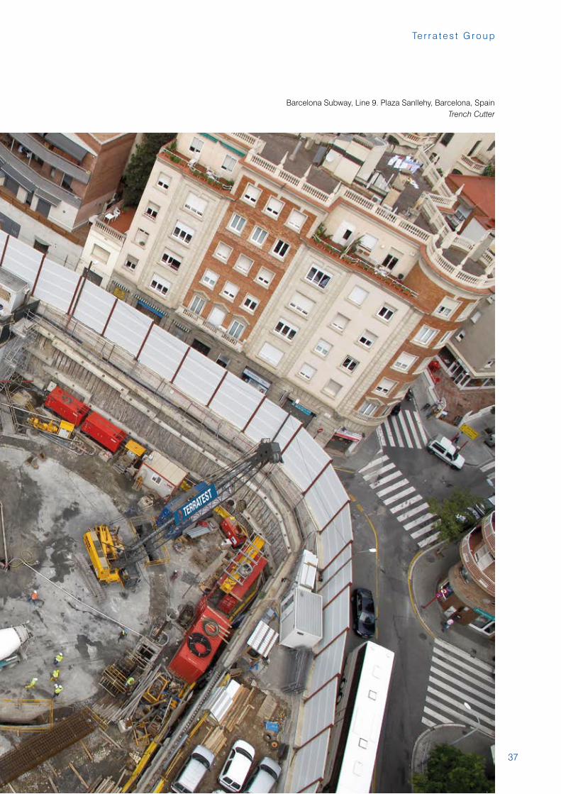
Barcelona Subway, Line 9. Plaza Sanllehy, Barcelona, Spain Trench Cutter
38
R e f e r e n c e s
39
Te r r a t e s t G r o u p
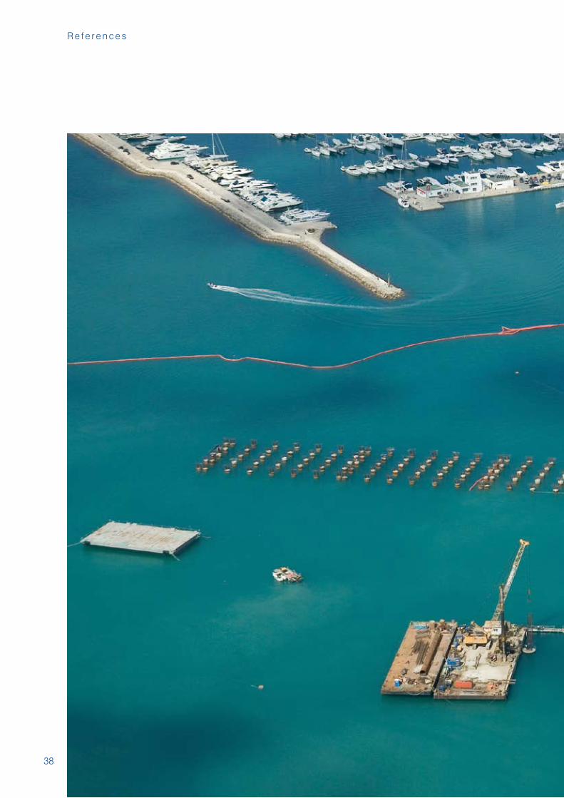
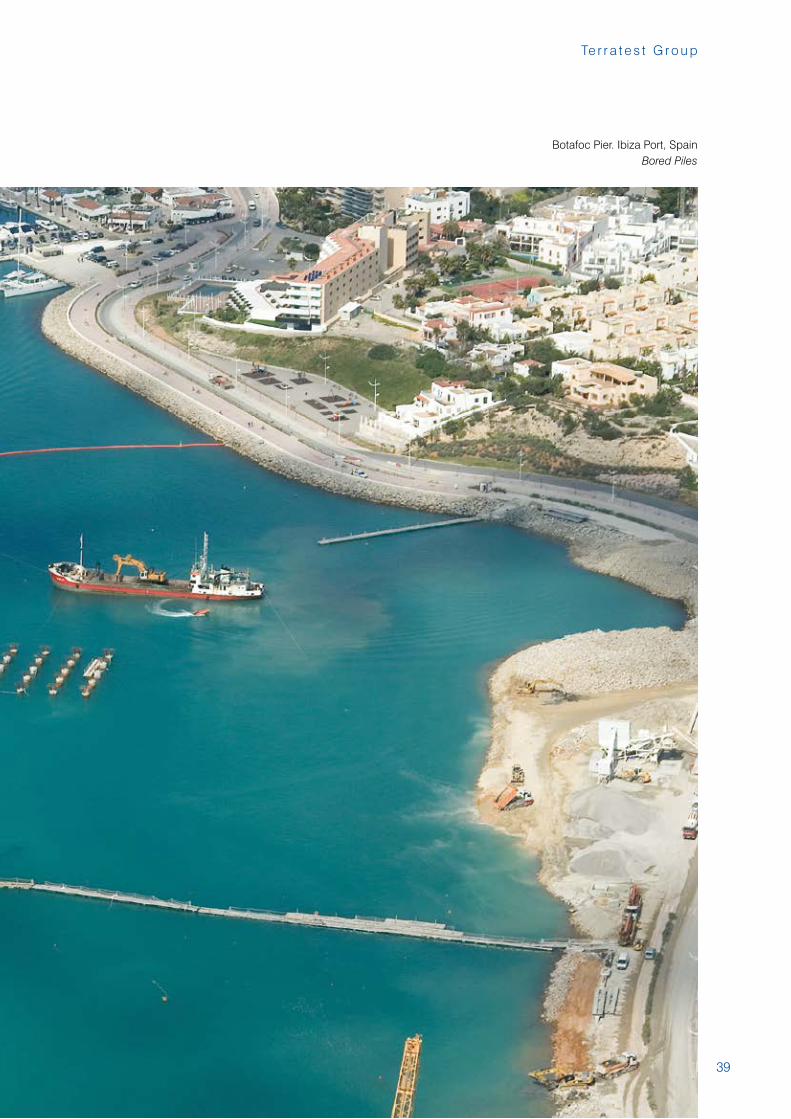
Botafoc Pier. Ibiza Port, SpainBored Piles
40
R e f e r e n c e s
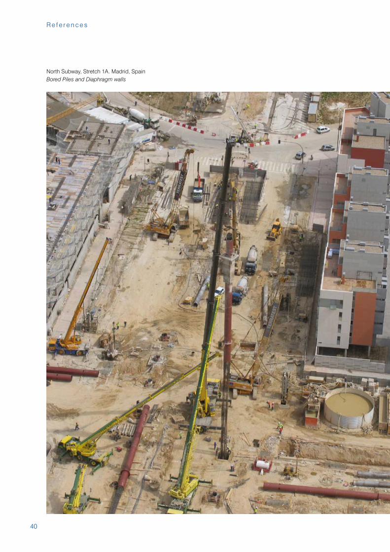
North Subway, Stretch 1A. Madrid, SpainBored Piles and Diaphragm walls
41
Te r r a t e s t G r o u p
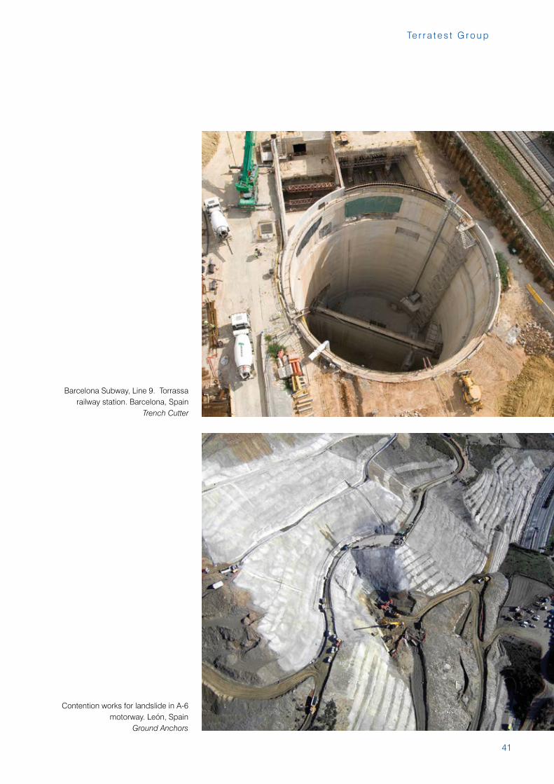
Contention works for landslide in A-6 motorway. León, Spain
Ground Anchors
Barcelona Subway, Line 9. Torrassa railway station. Barcelona, Spain
Trench Cutter
42
R e f e r e n c e s
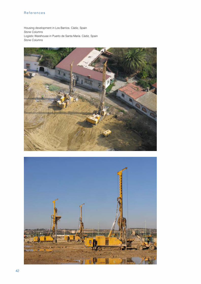
Housing development in Los Barrios. Cádiz, SpainStone ColumnsLogistic Warehouse in Puerto de Santa María. Cádiz, SpainStone Columns
43
Te r r a t e s t G r o u p
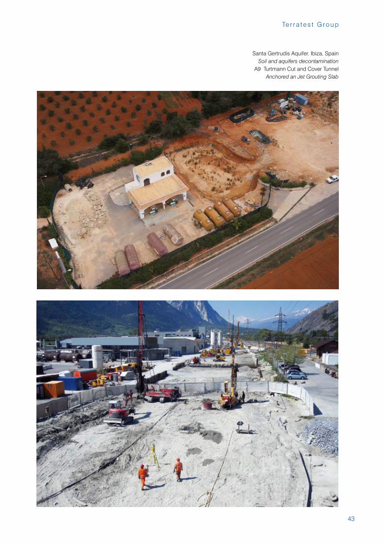
Santa Gertrudis Aquifer. Ibiza, SpainSoil and aquifers decontamination
A9 Turtmann Cut and Cover Tunnel Anchored an Jet Grouting Slab
44
R e f e r e n c e s
45
Te r r a t e s t G r o u p
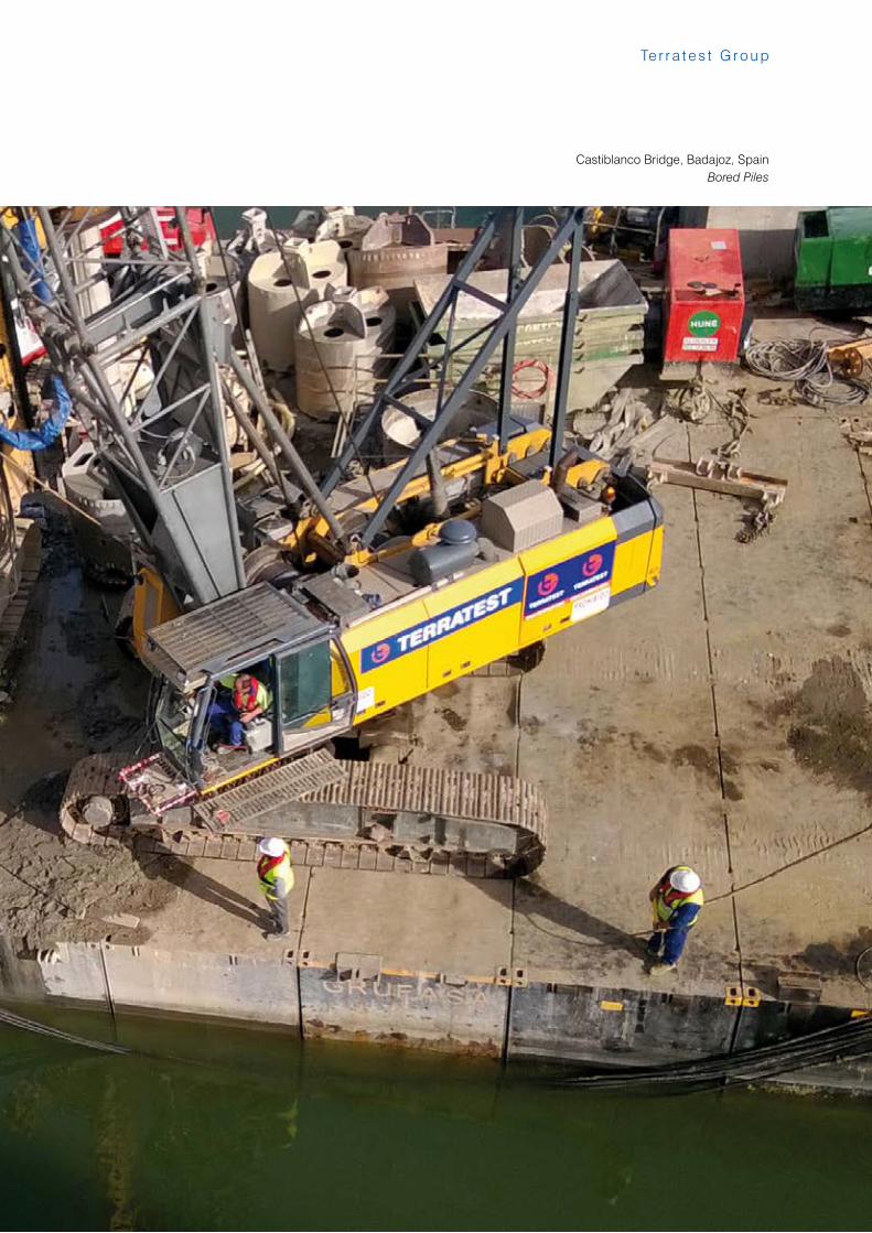
Castiblanco Bridge, Badajoz, SpainBored Piles
46
R e f e r e n c e s
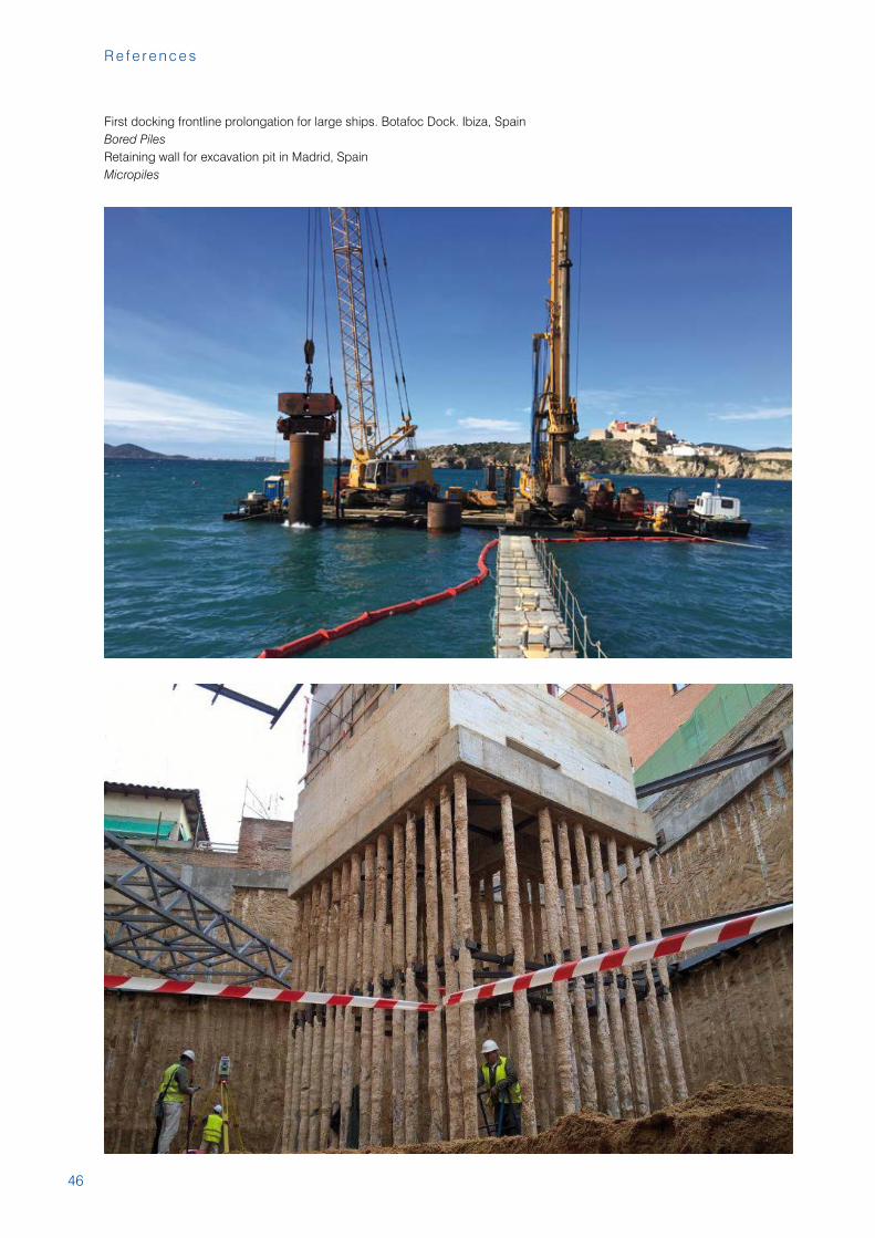
First docking frontline prolongation for large ships. Botafoc Dock. Ibiza, SpainBored PilesRetaining wall for excavation pit in Madrid, SpainMicropiles
47
Te r r a t e s t G r o u p
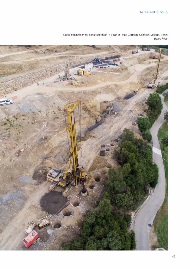
Slope stabilization for construction of 15 Villas in Finca Cortesín. Casares. Malaga, SpainBored Piles
48
R e f e r e n c e s
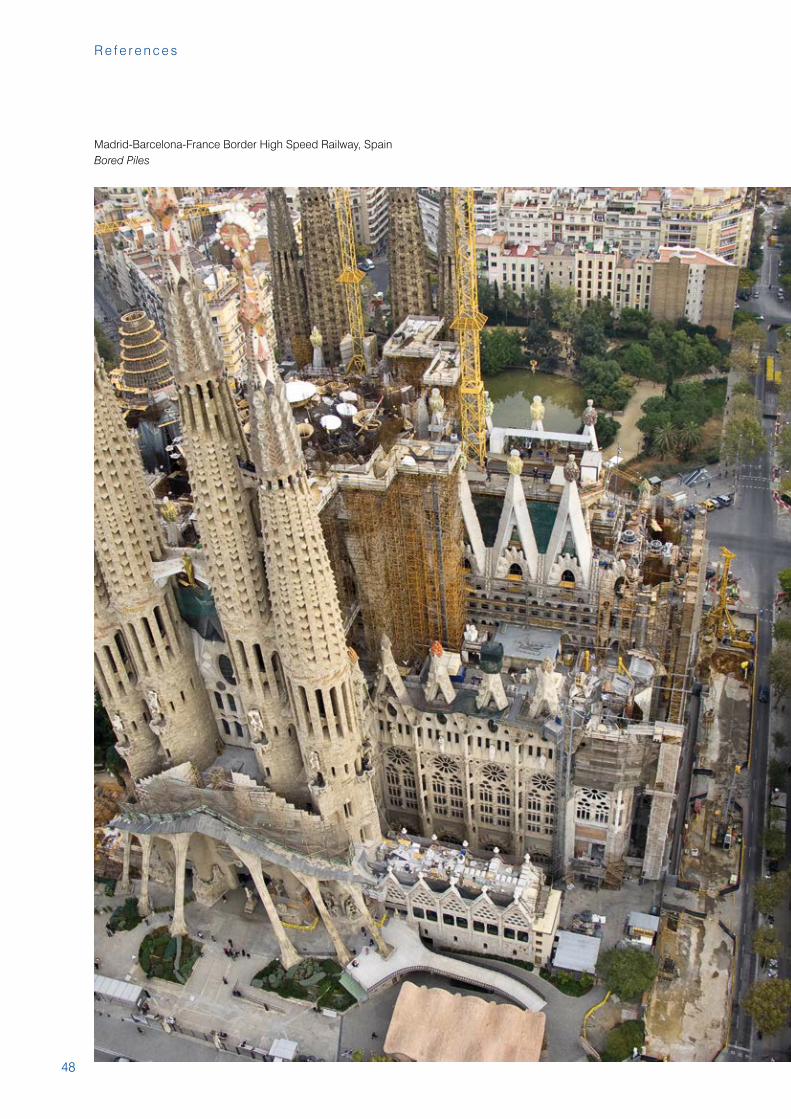
Madrid-Barcelona-France Border High Speed Railway, SpainBored Piles
49
Te r r a t e s t G r o u p
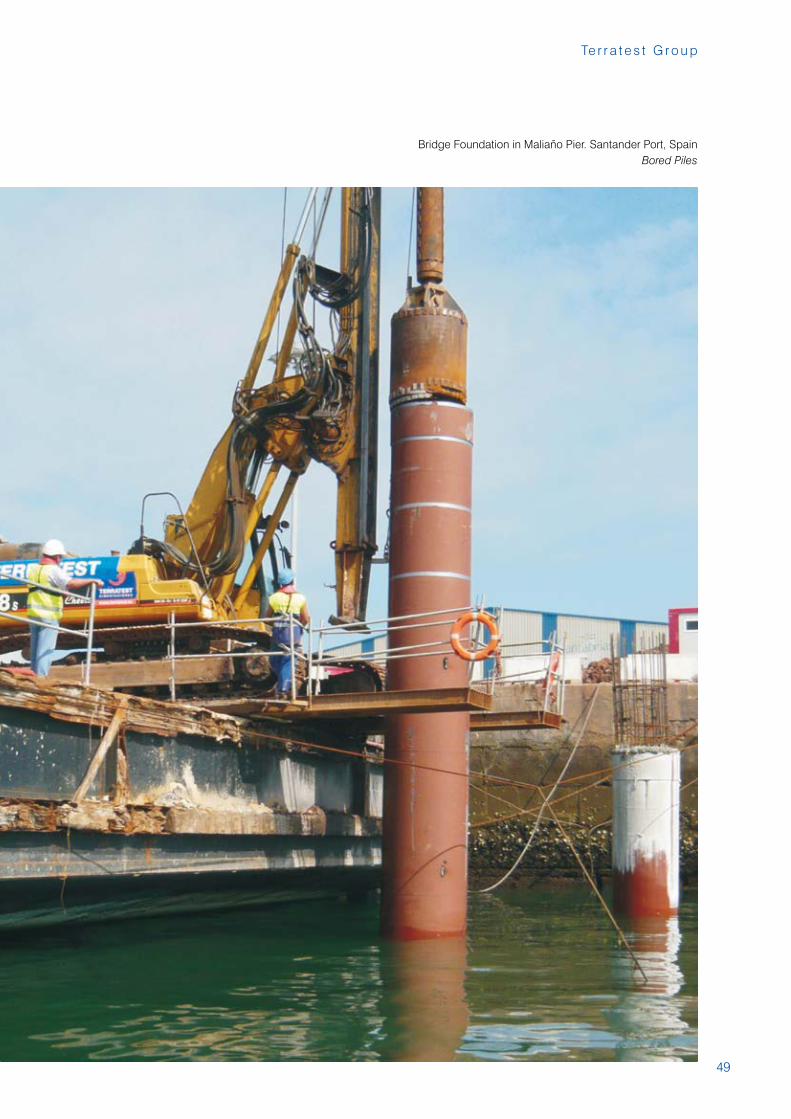
Bridge Foundation in Maliaño Pier. Santander Port, SpainBored Piles

50
R e f e r e n c e s
Manzanal Bridge over Ricobayo Dam, SpainBored Piles
51
Te r r a t e s t G r o u p
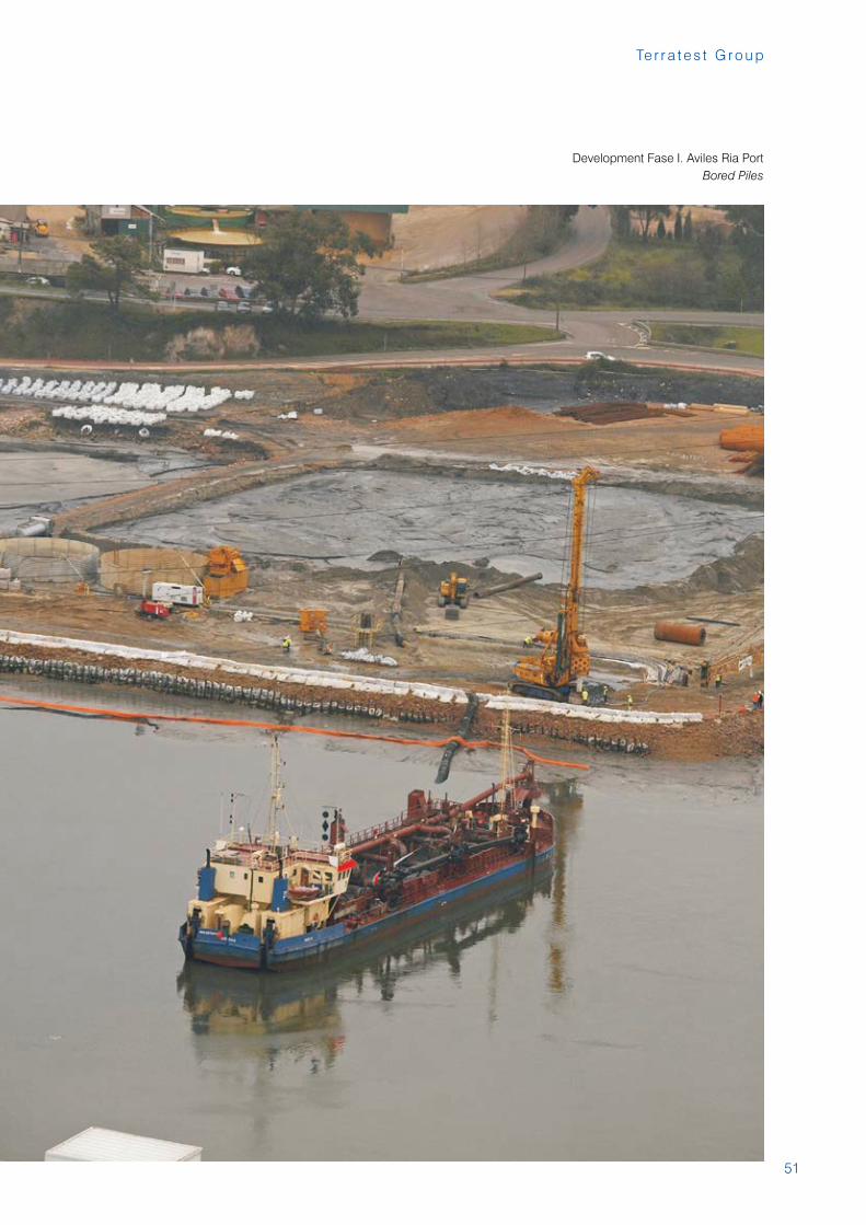
Development Fase I. Aviles Ria PortBored Piles
52
R e f e r e n c e s
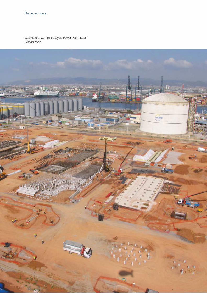
Gas Natural Combined Cycle Power Plant, SpainPrecast Piles
53
Te r r a t e s t G r o u p
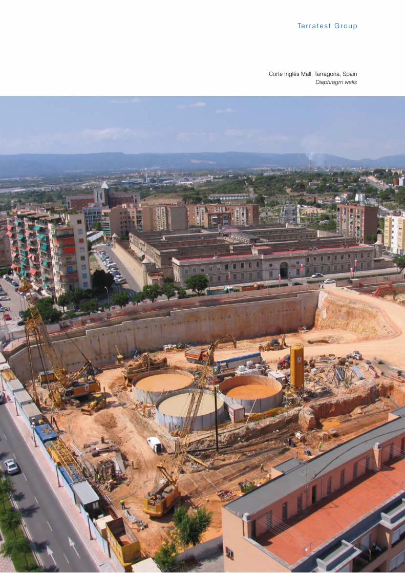
Corte Inglés Mall, Tarragona, SpainDiaphragm walls
54
R e f e r e n c e s
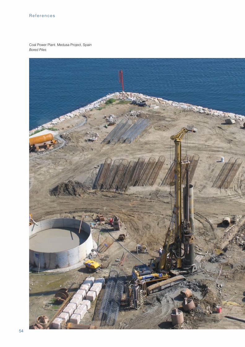
Coal Power Plant. Medusa Project, SpainBored Piles
55
Te r r a t e s t G r o u p
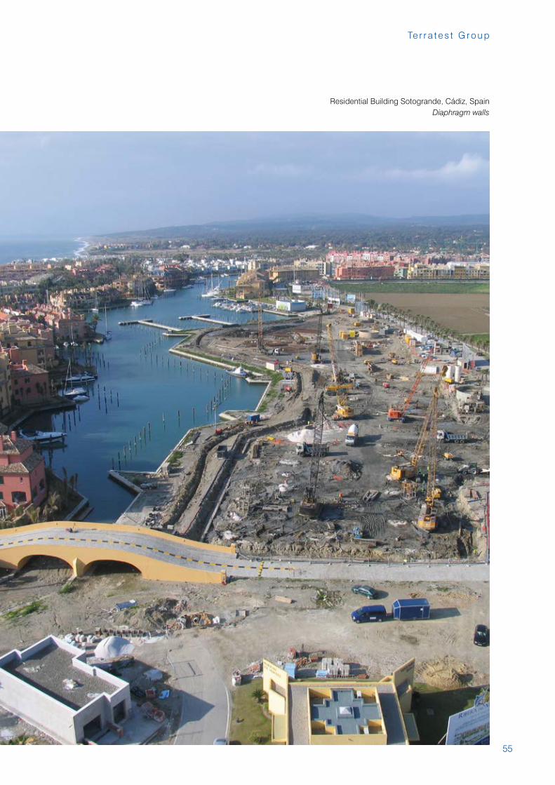
Residential Building Sotogrande, Cádiz, SpainDiaphragm walls
56
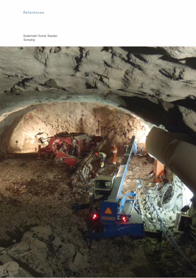
Sodermalm Tunnel. SwedenTunneling
R e f e r e n c e s
57
Te r r a t e s t G r o u p
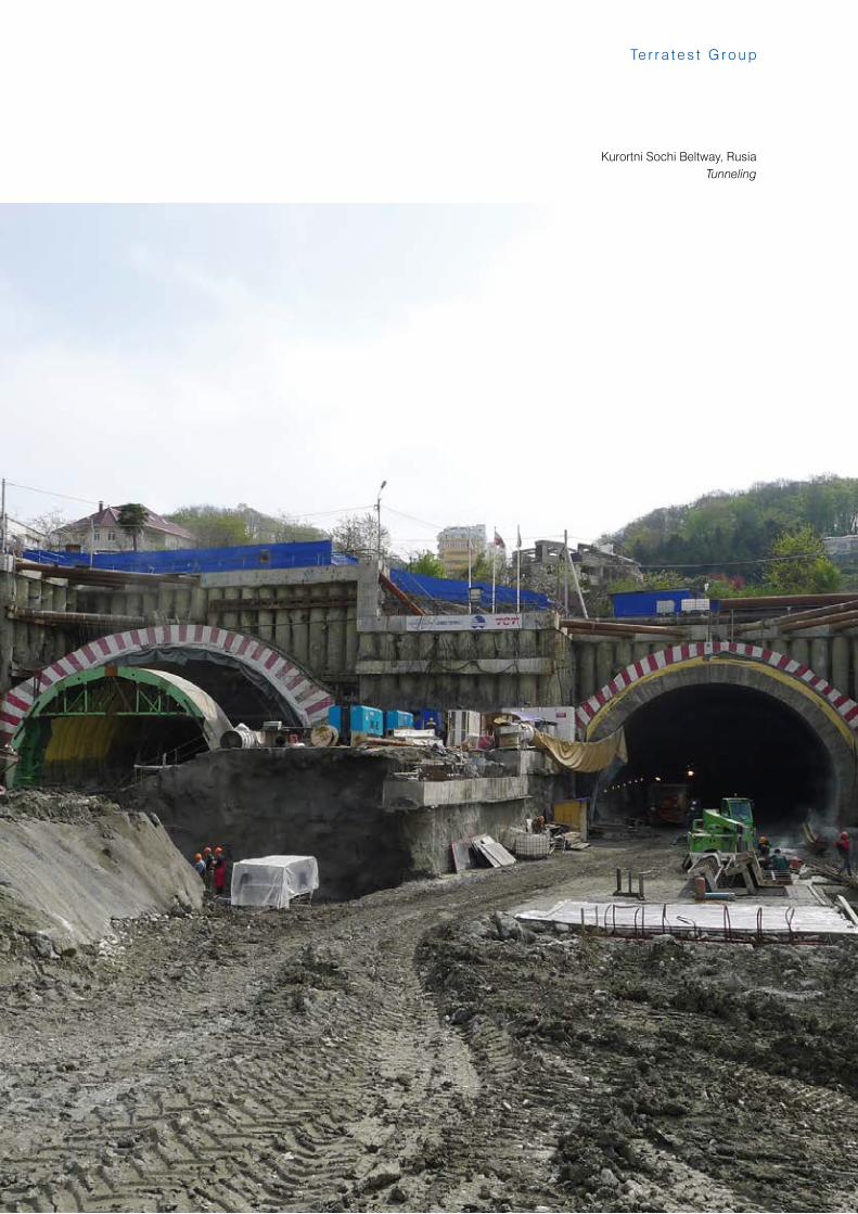
Kurortni Sochi Beltway, Rusia Tunneling
58
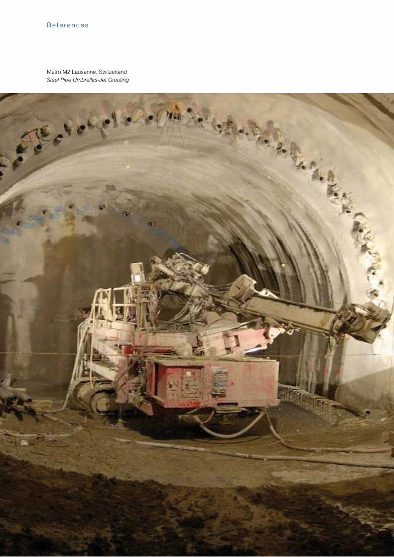
Metro M2 Lausanne, SwitzerlandSteel Pipe Umbrellas-Jet Grouting
R e f e r e n c e s
59
Te r r a t e s t G r o u p
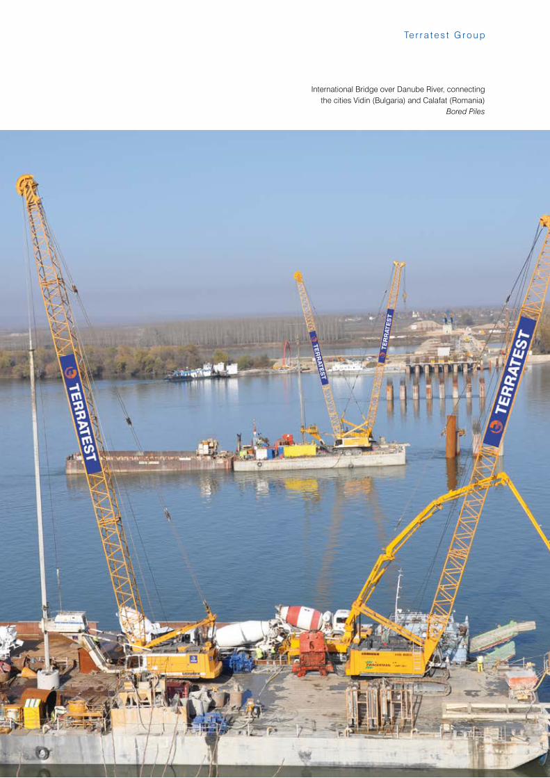
International Bridge over Danube River, connectingthe cities Vidin (Bulgaria) and Calafat (Romania)
Bored Piles
60
R e f e r e n c e s
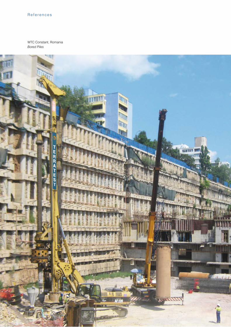
WTC Constant, RomaniaBored Piles
61
Te r r a t e s t G r o u p
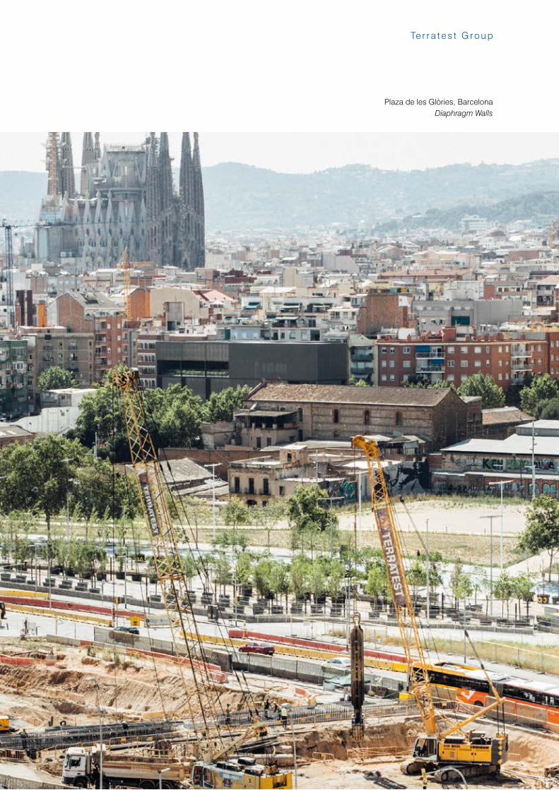
Plaza de les Glòries, BarcelonaDiaphragm Walls
62
R e f e r e n c e s
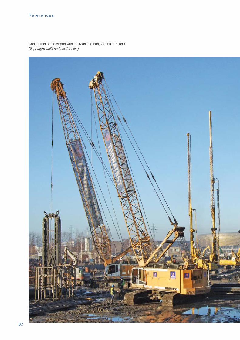
Connection of the Airport with the Maritime Port, Gdansk, PolandDiaphragm walls and Jet Grouting
63
Te r r a t e s t G r o u p
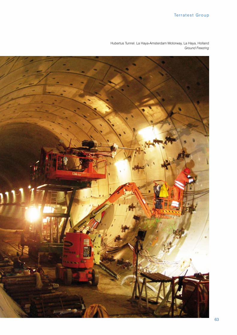
Hubertus Tunnel. La Haya-Amsterdam Motorway, La Haya, HollandGround Freezing
64
R e f e r e n c e s
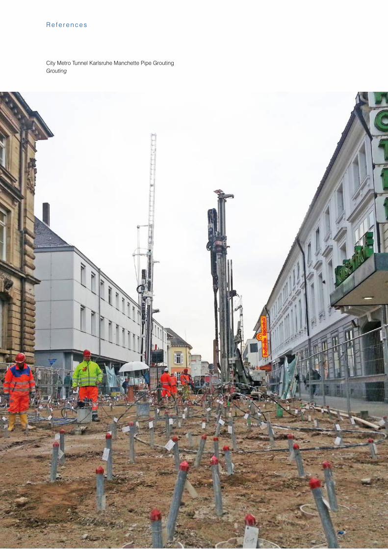
City Metro Tunnel Karlsruhe Manchette Pipe GroutingGrouting
65
Te r r a t e s t G r o u p
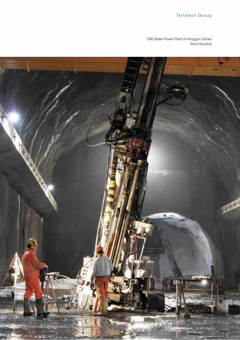
2ND Water Power Plant of Honggrin LémanRock Grouting
66
R e f e r e n c e s
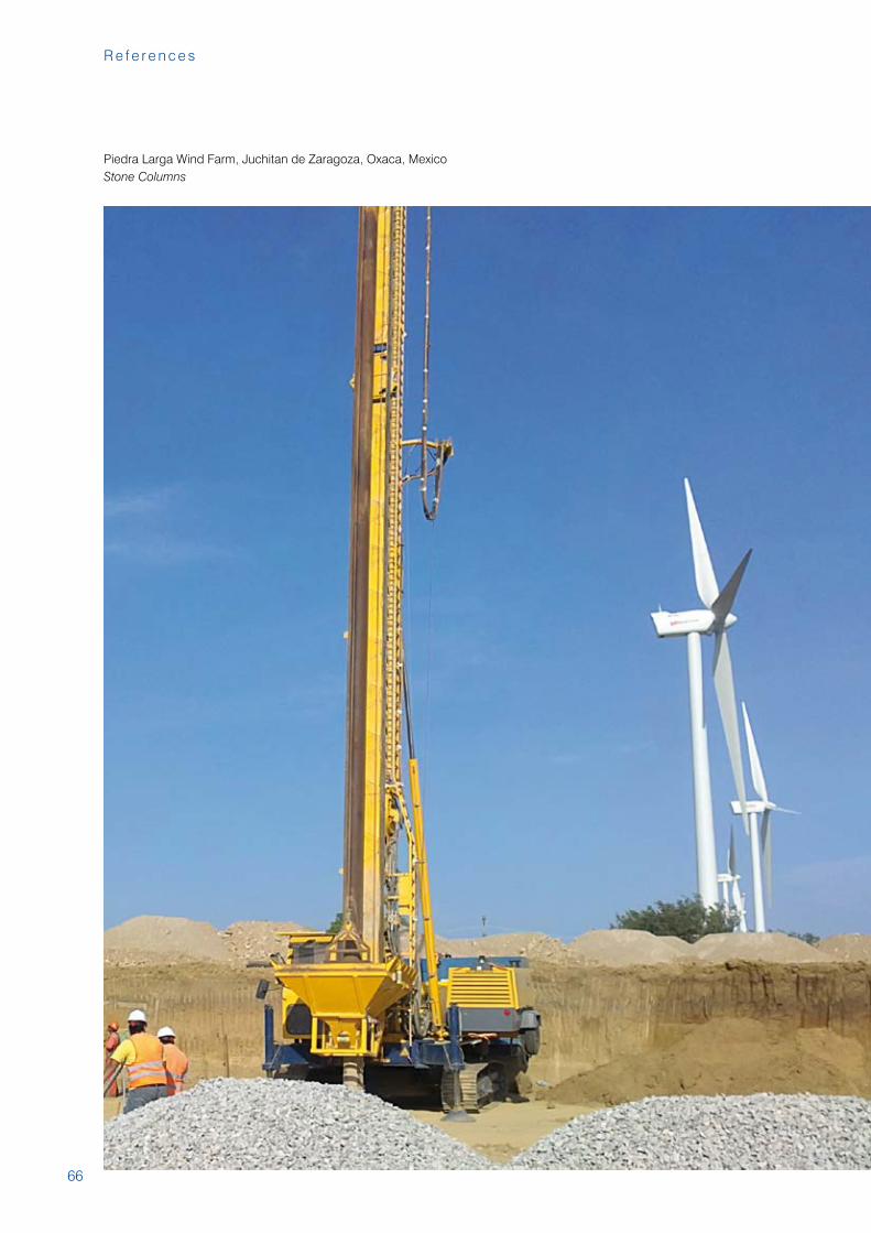
Piedra Larga Wind Farm, Juchitan de Zaragoza, Oxaca, MexicoStone Columns
67
Te r r a t e s t G r o u p
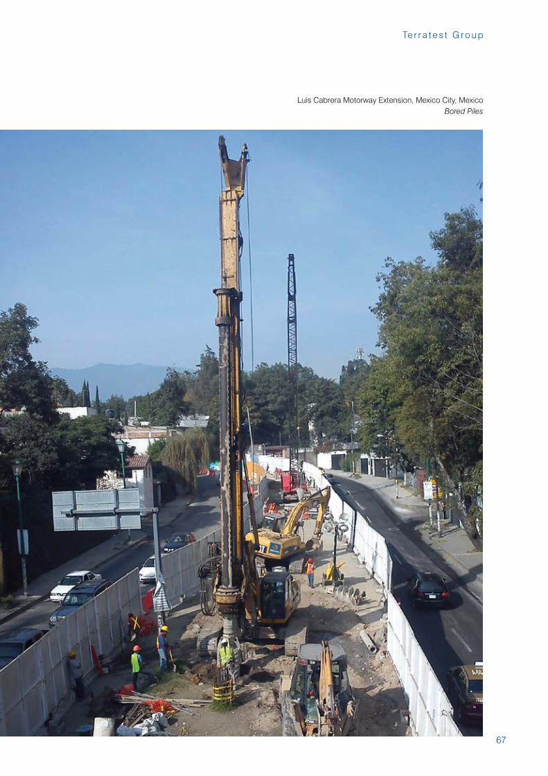
Luis Cabrera Motorway Extension, Mexico City, MexicoBored Piles
68
R e f e r e n c e s
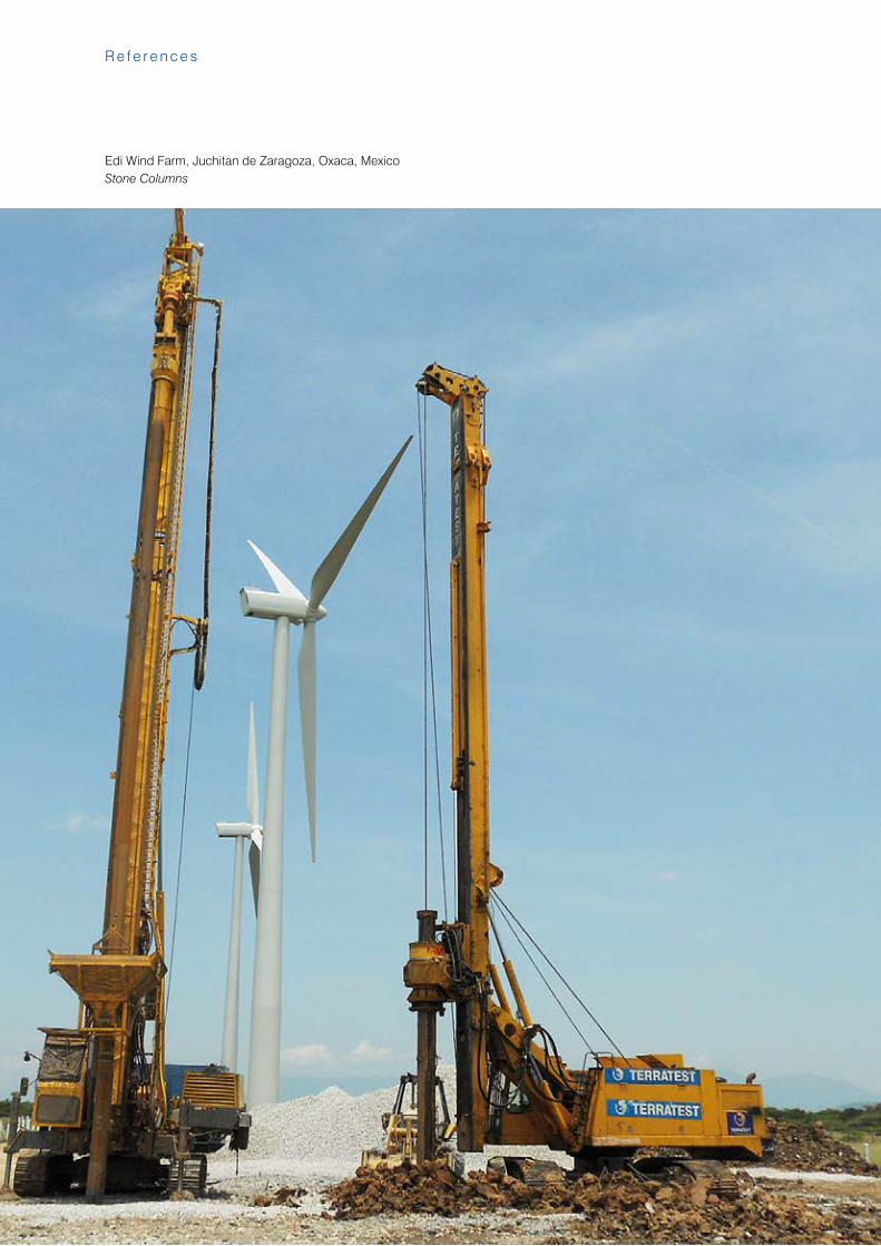
Edi Wind Farm, Juchitan de Zaragoza, Oxaca, MexicoStone Columns
69
Te r r a t e s t G r o u p
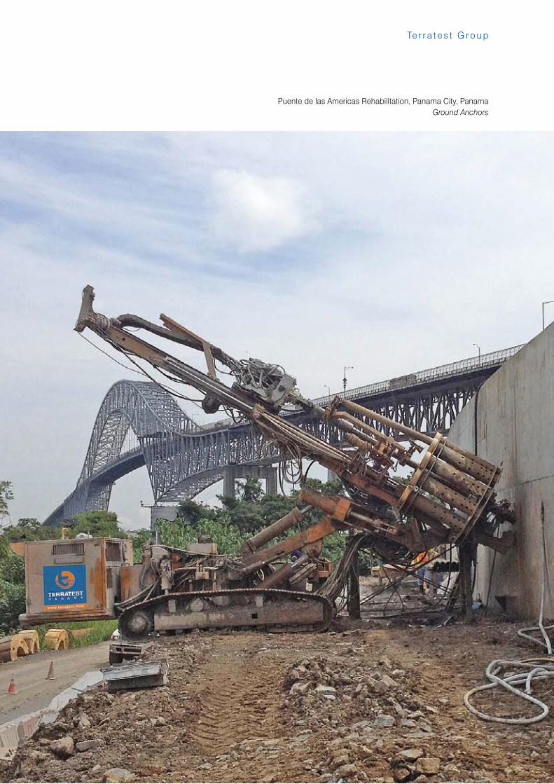
Puente de las Americas Rehabilitation, Panama City, PanamaGround Anchors
70
R e f e r e n c e s
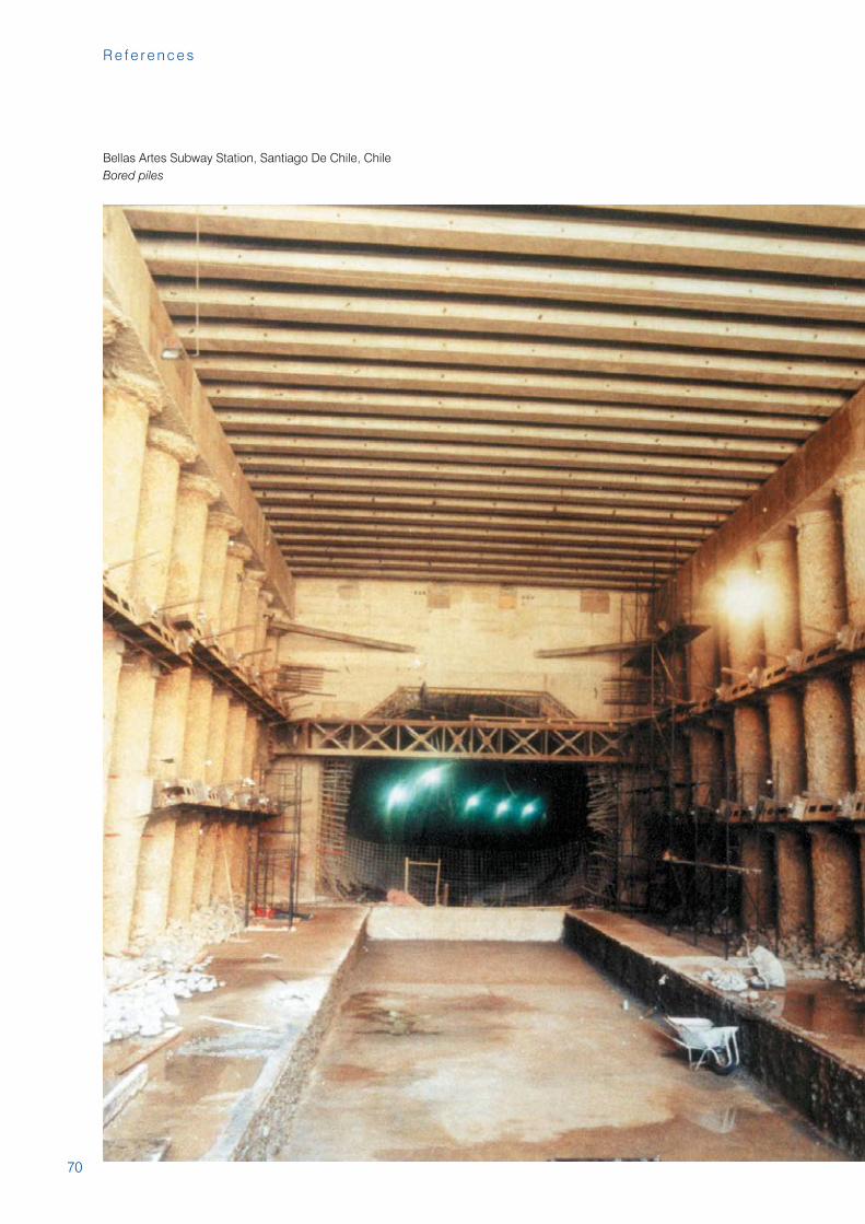
Bellas Artes Subway Station, Santiago De Chile, ChileBored piles
71
Te r r a t e s t G r o u p
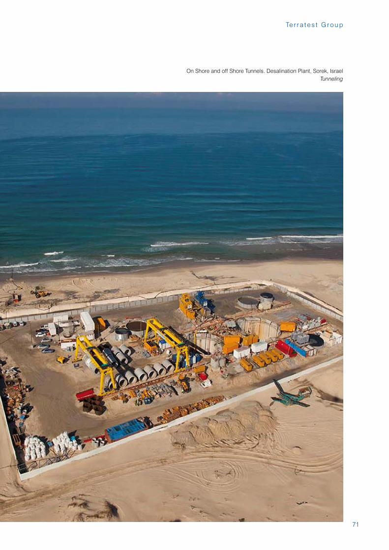
On Shore and off Shore Tunnels. Desalination Plant, Sorek, IsraelTunneling
72
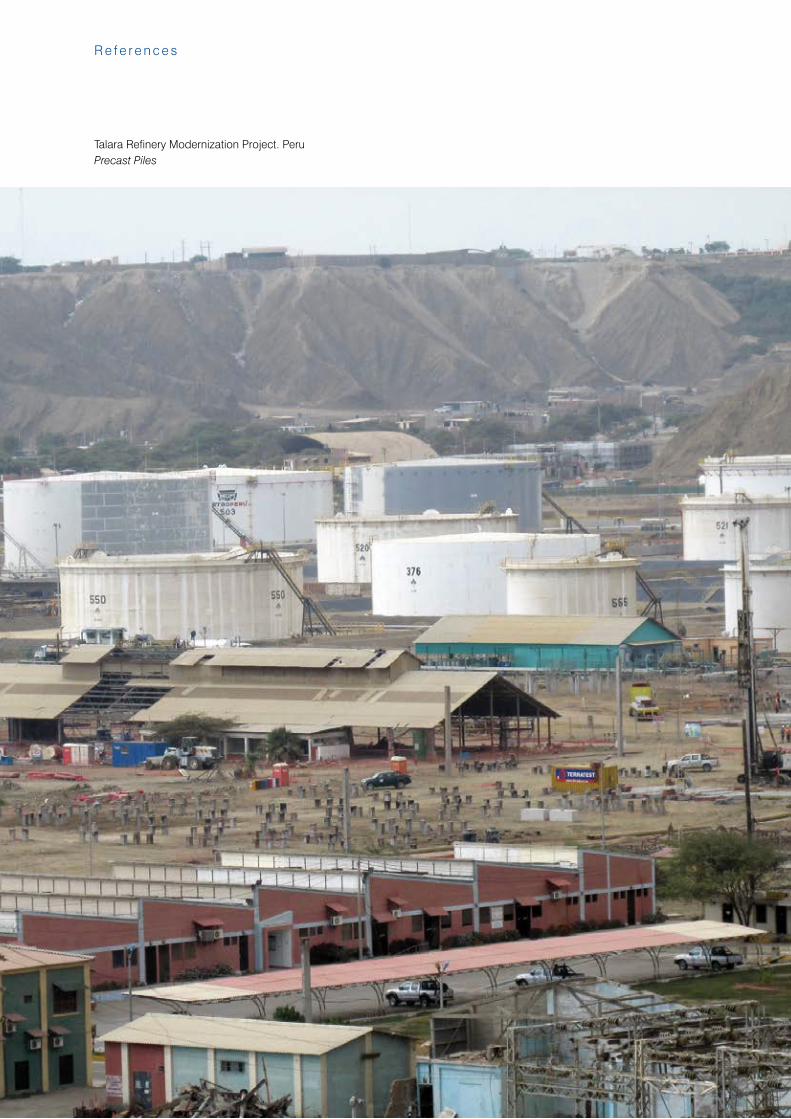
Talara Refinery Modernization Project. Peru Precast Piles
R e f e r e n c e s
73
Te r r a t e s t G r o u p
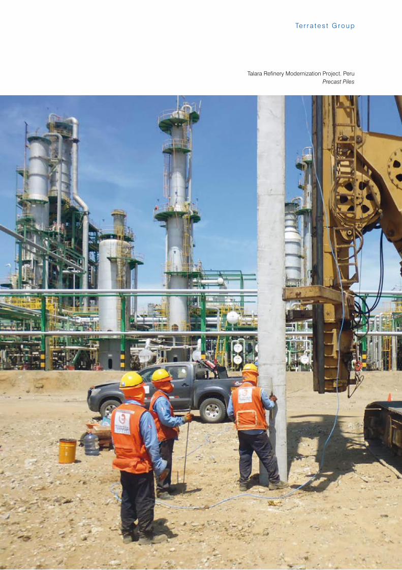
Talara Refinery Modernization Project. Peru Precast Piles
74
R e f e r e n c e s
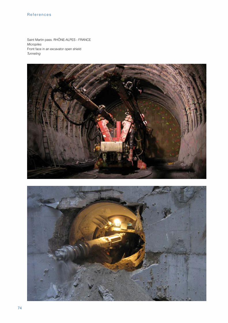
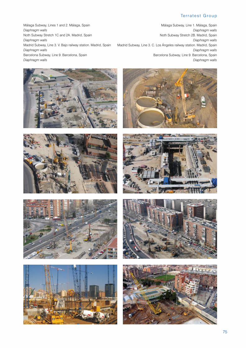
Saint Martin pass. RHÔNE-ALPES - FRANCEMicropilesFront face in an excavator open shieldTunneling
75
Te r r a t e s t G r o u p
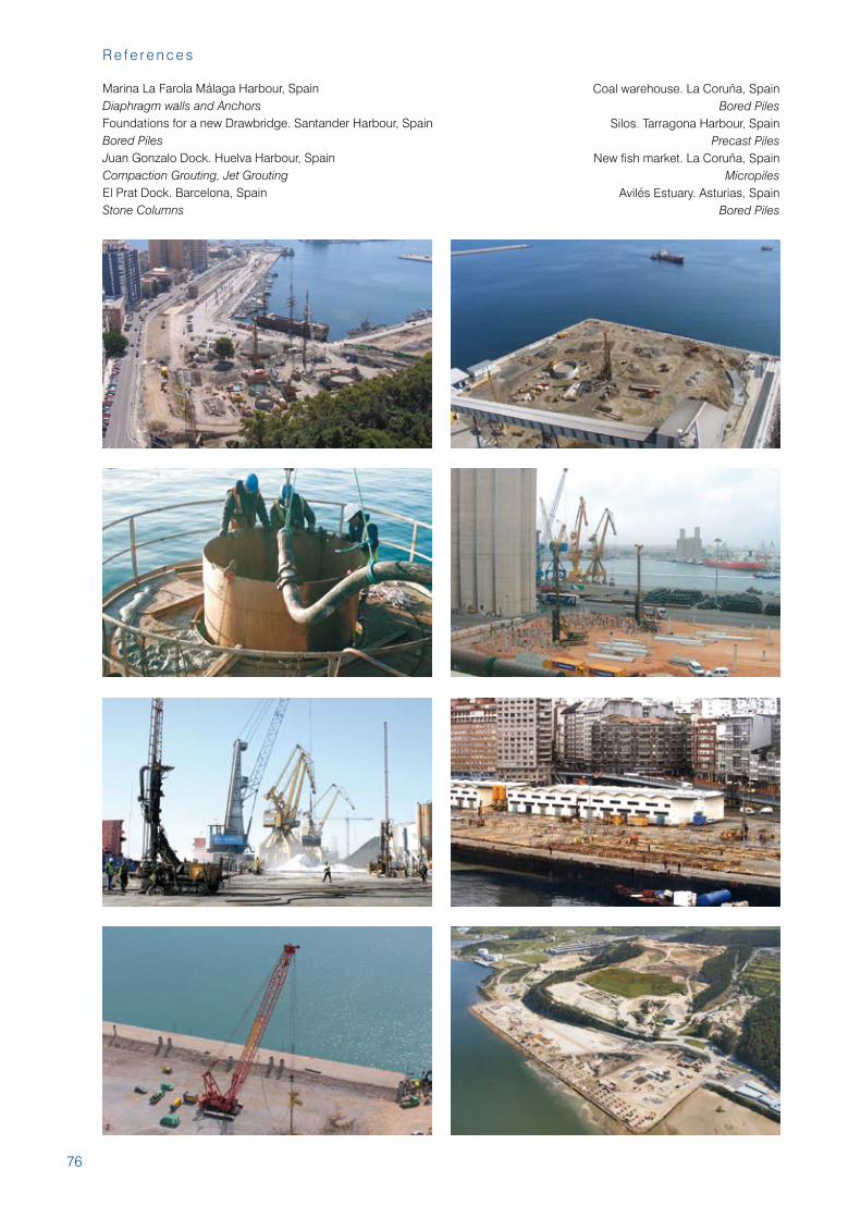
Málaga Subway, Lines 1 and 2. Málaga, Spain
Diaphragm walls
Noth Subway Stretch 1C and 2A. Madrid, Spain
Diaphragm walls
Madrid Subway, Line 3. V. Bajo railway station. Madrid, Spain
Diaphragm walls
Barcelona Subway, Line 9. Barcelona, Spain
Diaphragm walls
Málaga Subway, Line 1. Málaga, Spain
Diaphragm walls
Noth Subway Stretch 2B. Madrid, Spain
Diaphragm walls
Madrid Subway, Line 3. C. Los Ángeles railway station. Madrid, Spain
Diaphragm walls
Barcelona Subway, Line 9. Barcelona, Spain
Diaphragm walls
76
R e f e r e n c e s
Marina La Farola Málaga Harbour, SpainDiaphragm walls and AnchorsFoundations for a new Drawbridge. Santander Harbour, Spain Bored PilesJuan Gonzalo Dock. Huelva Harbour, SpainCompaction Grouting, Jet GroutingEl Prat Dock. Barcelona, SpainStone Columns
Coal warehouse. La Coruña, SpainBored Piles
Silos. Tarragona Harbour, SpainPrecast Piles
New fish market. La Coruña, SpainMicropiles
Avilés Estuary. Asturias, SpainBored Piles
77
Te r r a t e s t G r o u p
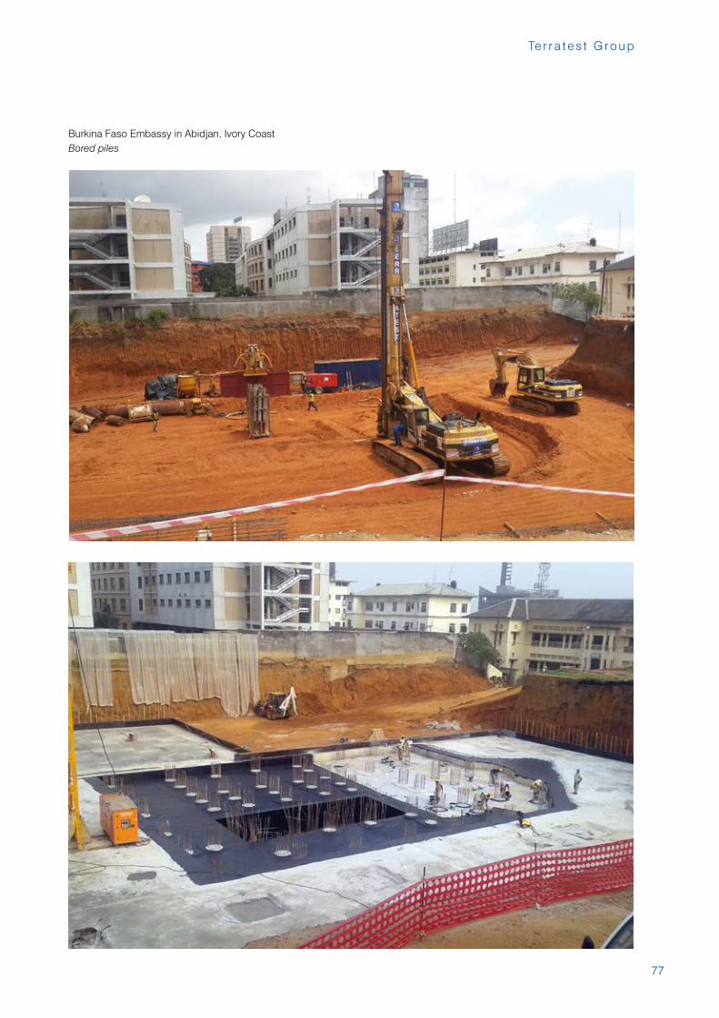
Burkina Faso Embassy in Abidjan, Ivory CoastBored piles
78
R e f e r e n c e s
79
Te r r a t e s t G r o u p
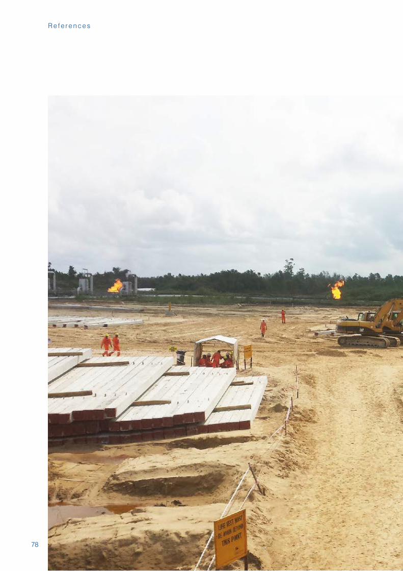
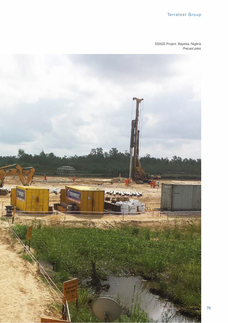
SSAGS Project. Bayelsa. NigériaPrecast piles
80
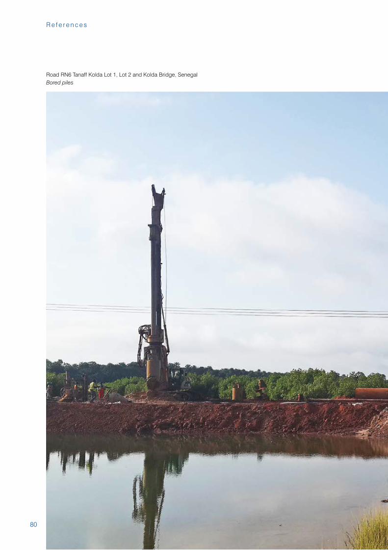
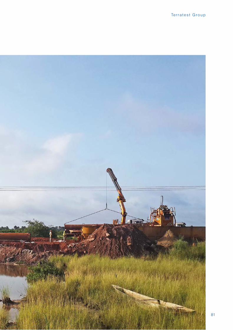
Road RN6 Tanaff Kolda Lot 1, Lot 2 and Kolda Bridge, Senegal Bored piles
R e f e r e n c e s
81
Te r r a t e s t G r o u p
82
R e f e r e n c e s
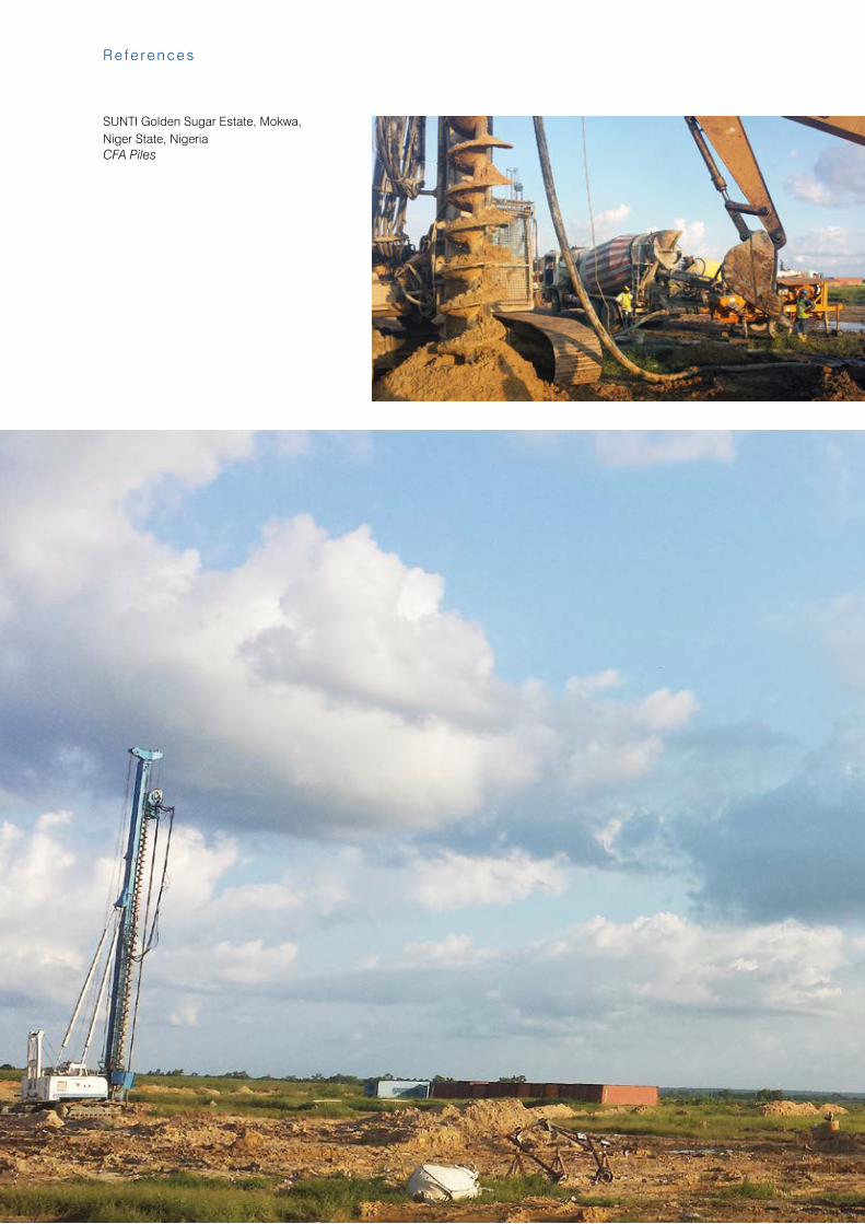
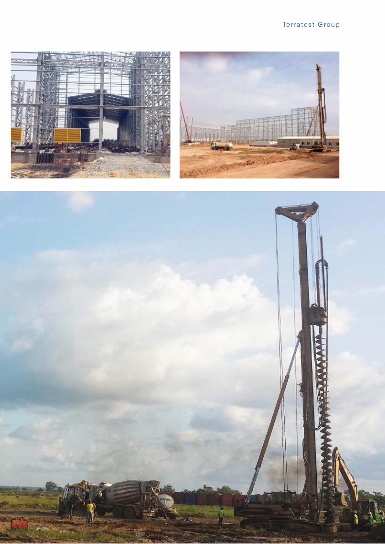
SUNTI Golden Sugar Estate, Mokwa, Niger State, NigeriaCFA Piles
83
Te r r a t e s t G r o u p
84
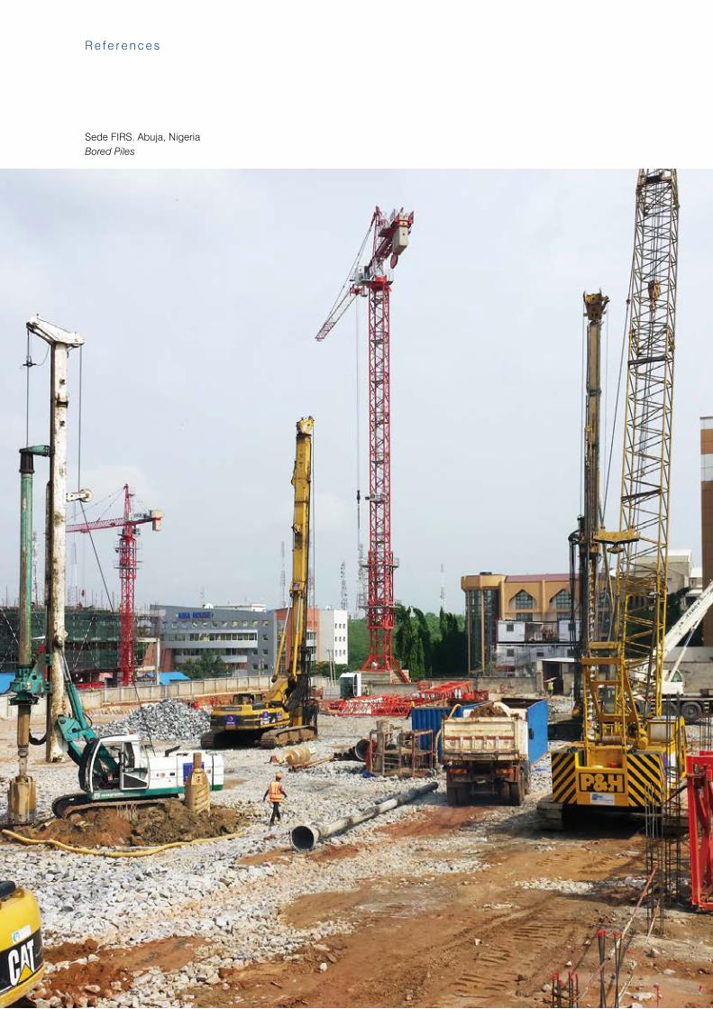
Sede FIRS. Abuja, NigeriaBored Piles
R e f e r e n c e s
85
Te r r a t e s t G r o u p
85
R e f e r e n c e s
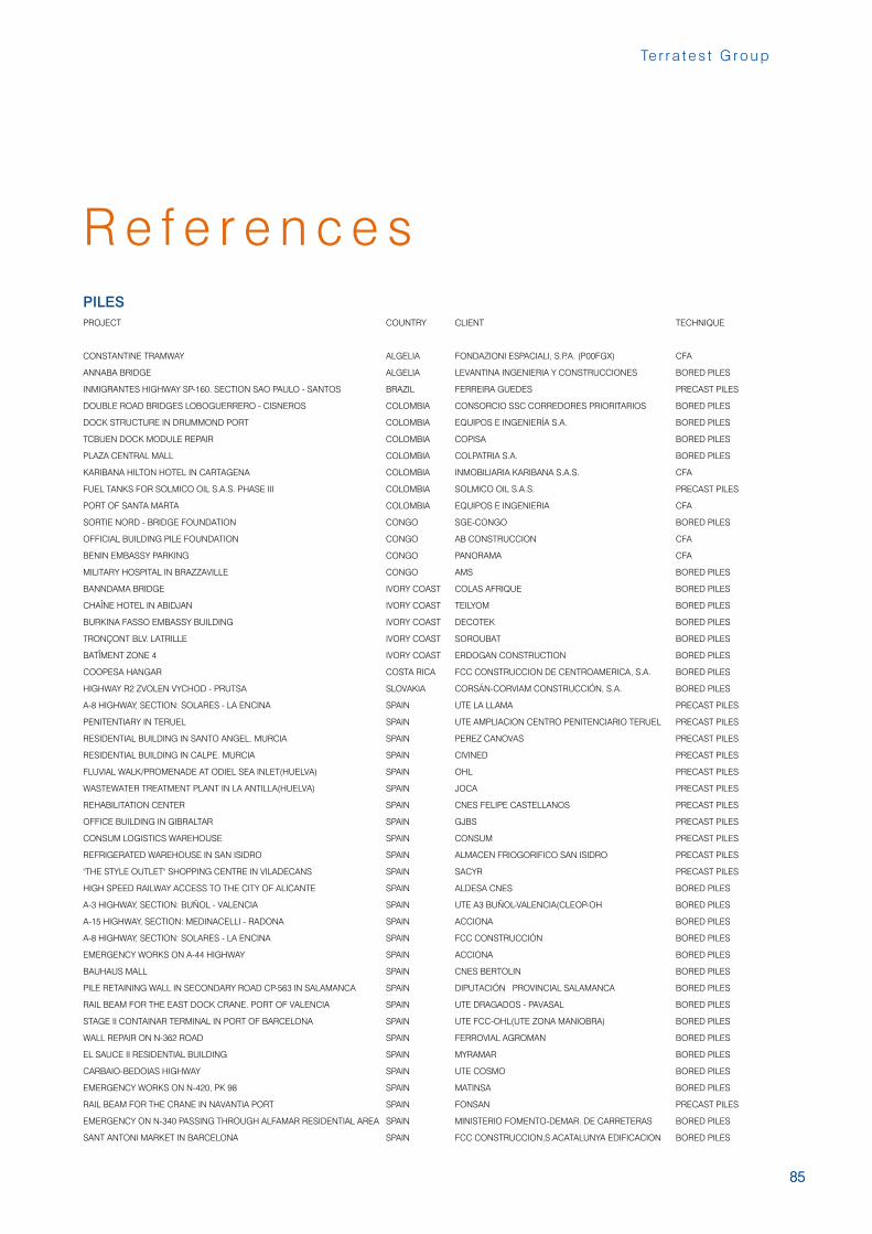
PROJECT COUNTRY CLIENT TECHNIQUE
CONSTANTINE TRAMWAY ALGELIA FONDAZIONI ESPACIALI, S.P.A. (P00FGX) CFA
ANNABA BRIDGE ALGELIA LEVANTINA INGENIERIA Y CONSTRUCCIONES BORED PILES
INMIGRANTES HIGHWAY SP-160. SECTION SAO PAULO - SANTOS BRAZIL FERREIRA GUEDES PRECAST PILES
DOUBLE ROAD BRIDGES LOBOGUERRERO - CISNEROS COLOMBIA CONSORCIO SSC CORREDORES PRIORITARIOS BORED PILES
DOCK STRUCTURE IN DRUMMOND PORT COLOMBIA EQUIPOS E INGENIERÍA S.A. BORED PILES
TCBUEN DOCK MODULE REPAIR COLOMBIA COPISA BORED PILES
PLAZA CENTRAL MALL COLOMBIA COLPATRIA S.A. BORED PILES
KARIBANA HILTON HOTEL IN CARTAGENA COLOMBIA INMOBILIARIA KARIBANA S.A.S. CFA
FUEL TANKS FOR SOLMICO OIL S.A.S. PHASE III COLOMBIA SOLMICO OIL S.A.S. PRECAST PILES
PORT OF SANTA MARTA COLOMBIA EQUIPOS E INGENIERIA CFA
SORTIE NORD - BRIDGE FOUNDATION CONGO SGE-CONGO BORED PILES
OFFICIAL BUILDING PILE FOUNDATION CONGO AB CONSTRUCCION CFA
BENIN EMBASSY PARKING CONGO PANORAMA CFA
MILITARY HOSPITAL IN BRAZZAVILLE CONGO AMS BORED PILES
BANNDAMA BRIDGE IVORY COAST COLAS AFRIQUE BORED PILES
CHAÎNE HOTEL IN ABIDJAN IVORY COAST TEILYOM BORED PILES
BURKINA FASSO EMBASSY BUILDING IVORY COAST DECOTEK BORED PILES
TRONÇONT BLV. LATRILLE IVORY COAST SOROUBAT BORED PILES
BATÎMENT ZONE 4 IVORY COAST ERDOGAN CONSTRUCTION BORED PILES
COOPESA HANGAR COSTA RICA FCC CONSTRUCCION DE CENTROAMERICA, S.A. BORED PILES
HIGHWAY R2 ZVOLEN VYCHOD - PRUTSA SLOVAKIA CORSÁN-CORVIAM CONSTRUCCIÓN, S.A. BORED PILES
A-8 HIGHWAY, SECTION: SOLARES - LA ENCINA SPAIN UTE LA LLAMA PRECAST PILES
PENITENTIARY IN TERUEL SPAIN UTE AMPLIACION CENTRO PENITENCIARIO TERUEL PRECAST PILES
RESIDENTIAL BUILDING IN SANTO ANGEL. MURCIA SPAIN PEREZ CANOVAS PRECAST PILES
RESIDENTIAL BUILDING IN CALPE. MURCIA SPAIN CIVINED PRECAST PILES
FLUVIAL WALK/PROMENADE AT ODIEL SEA INLET(HUELVA) SPAIN OHL PRECAST PILES
WASTEWATER TREATMENT PLANT IN LA ANTILLA(HUELVA) SPAIN JOCA PRECAST PILES
REHABILITATION CENTER SPAIN CNES FELIPE CASTELLANOS PRECAST PILES
OFFICE BUILDING IN GIBRALTAR SPAIN GJBS PRECAST PILES
CONSUM LOGISTICS WAREHOUSE SPAIN CONSUM PRECAST PILES
REFRIGERATED WAREHOUSE IN SAN ISIDRO SPAIN ALMACEN FRIOGORIFICO SAN ISIDRO PRECAST PILES
"THE STYLE OUTLET" SHOPPING CENTRE IN VILADECANS SPAIN SACYR PRECAST PILES
HIGH SPEED RAILWAY ACCESS TO THE CITY OF ALICANTE SPAIN ALDESA CNES BORED PILES
A-3 HIGHWAY, SECTION: BUÑOL - VALENCIA SPAIN UTE A3 BUÑOL-VALENCIA(CLEOP-OH BORED PILES
A-15 HIGHWAY, SECTION: MEDINACELLI - RADONA SPAIN ACCIONA BORED PILES
A-8 HIGHWAY, SECTION: SOLARES - LA ENCINA SPAIN FCC CONSTRUCCIÓN BORED PILES
EMERGENCY WORKS ON A-44 HIGHWAY SPAIN ACCIONA BORED PILES
BAUHAUS MALL SPAIN CNES BERTOLIN BORED PILES
PILE RETAINING WALL IN SECONDARY ROAD CP-563 IN SALAMANCA SPAIN DIPUTACIÓN PROVINCIAL SALAMANCA BORED PILES
RAIL BEAM FOR THE EAST DOCK CRANE. PORT OF VALENCIA SPAIN UTE DRAGADOS - PAVASAL BORED PILES
STAGE II CONTAINAR TERMINAL IN PORT OF BARCELONA SPAIN UTE FCC-OHL(UTE ZONA MANIOBRA) BORED PILES
WALL REPAIR ON N-362 ROAD SPAIN FERROVIAL AGROMAN BORED PILES
EL SAUCE II RESIDENTIAL BUILDING SPAIN MYRAMAR BORED PILES
CARBAIO-BEDOIAS HIGHWAY SPAIN UTE COSMO BORED PILES
EMERGENCY WORKS ON N-420, PK 98 SPAIN MATINSA BORED PILES
RAIL BEAM FOR THE CRANE IN NAVANTIA PORT SPAIN FONSAN PRECAST PILES
EMERGENCY ON N-340 PASSING THROUGH ALFAMAR RESIDENTIAL AREA SPAIN MINISTERIO FOMENTO-DEMAR. DE CARRETERAS BORED PILES
SANT ANTONI MARKET IN BARCELONA SPAIN FCC CONSTRUCCION,S.ACATALUNYA EDIFICACION BORED PILES
PILES
86
R e f e r e n c e s
PROJECT COUNTRY CLIENT TECHNIQUE
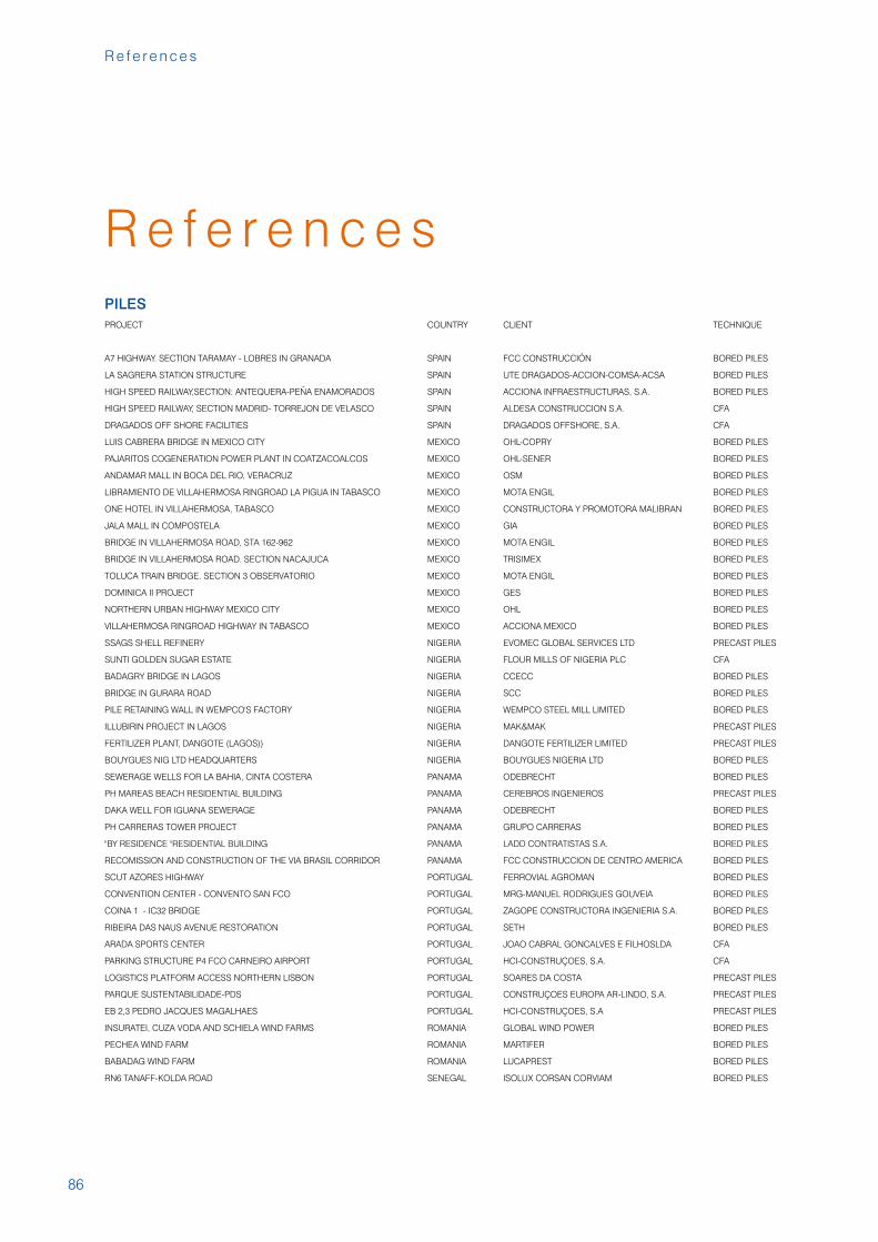
A7 HIGHWAY. SECTION TARAMAY - LOBRES IN GRANADA SPAIN FCC CONSTRUCCIÓN BORED PILES
LA SAGRERA STATION STRUCTURE SPAIN UTE DRAGADOS-ACCION-COMSA-ACSA BORED PILES
HIGH SPEED RAILWAY,SECTION: ANTEQUERA-PEÑA ENAMORADOS SPAIN ACCIONA INFRAESTRUCTURAS, S.A. BORED PILES
HIGH SPEED RAILWAY, SECTION MADRID- TORREJON DE VELASCO SPAIN ALDESA CONSTRUCCION S.A. CFA
DRAGADOS OFF SHORE FACILITIES SPAIN DRAGADOS OFFSHORE, S.A. CFA
LUIS CABRERA BRIDGE IN MEXICO CITY MEXICO OHL-COPRY BORED PILES
PAJARITOS COGENERATION POWER PLANT IN COATZACOALCOS MEXICO OHL-SENER BORED PILES
ANDAMAR MALL IN BOCA DEL RIO, VERACRUZ MEXICO OSM BORED PILES
LIBRAMIENTO DE VILLAHERMOSA RINGROAD LA PIGUA IN TABASCO MEXICO MOTA ENGIL BORED PILES
ONE HOTEL IN VILLAHERMOSA, TABASCO MEXICO CONSTRUCTORA Y PROMOTORA MALIBRAN BORED PILES
JALA MALL IN COMPOSTELA MEXICO GIA BORED PILES
BRIDGE IN VILLAHERMOSA ROAD, STA 162-962 MEXICO MOTA ENGIL BORED PILES
BRIDGE IN VILLAHERMOSA ROAD. SECTION NACAJUCA MEXICO TRISIMEX BORED PILES
TOLUCA TRAIN BRIDGE. SECTION 3 OBSERVATORIO MEXICO MOTA ENGIL BORED PILES
DOMINICA II PROJECT MEXICO GES BORED PILES
NORTHERN URBAN HIGHWAY MEXICO CITY MEXICO OHL BORED PILES
VILLAHERMOSA RINGROAD HIGHWAY IN TABASCO MEXICO ACCIONA MEXICO BORED PILES
SSAGS SHELL REFINERY NIGERIA EVOMEC GLOBAL SERVICES LTD PRECAST PILES
SUNTI GOLDEN SUGAR ESTATE NIGERIA FLOUR MILLS OF NIGERIA PLC CFA
BADAGRY BRIDGE IN LAGOS NIGERIA CCECC BORED PILES
BRIDGE IN GURARA ROAD NIGERIA SCC BORED PILES
PILE RETAINING WALL IN WEMPCO'S FACTORY NIGERIA WEMPCO STEEL MILL LIMITED BORED PILES
ILLUBIRIN PROJECT IN LAGOS NIGERIA MAK&MAK PRECAST PILES
FERTILIZER PLANT, DANGOTE (LAGOS)) NIGERIA DANGOTE FERTILIZER LIMITED PRECAST PILES
BOUYGUES NIG LTD HEADQUARTERS NIGERIA BOUYGUES NIGERIA LTD BORED PILES
SEWERAGE WELLS FOR LA BAHIA, CINTA COSTERA PANAMA ODEBRECHT BORED PILES
PH MAREAS BEACH RESIDENTIAL BUILDING PANAMA CEREBROS INGENIEROS PRECAST PILES
DAKA WELL FOR IGUANA SEWERAGE PANAMA ODEBRECHT BORED PILES
PH CARRERAS TOWER PROJECT PANAMA GRUPO CARRERAS BORED PILES
"BY RESIDENCE "RESIDENTIAL BUILDING PANAMA LADD CONTRATISTAS S.A. BORED PILES
RECOMISSION AND CONSTRUCTION OF THE VIA BRASIL CORRIDOR PANAMA FCC CONSTRUCCION DE CENTRO AMERICA BORED PILES
SCUT AZORES HIGHWAY PORTUGAL FERROVIAL AGROMAN BORED PILES
CONVENTION CENTER - CONVENTO SAN FCO PORTUGAL MRG-MANUEL RODRIGUES GOUVEIA BORED PILES
COINA 1 - IC32 BRIDGE PORTUGAL ZAGOPE CONSTRUCTORA INGENIERIA S.A. BORED PILES
RIBEIRA DAS NAUS AVENUE RESTORATION PORTUGAL SETH BORED PILES
ARADA SPORTS CENTER PORTUGAL JOAO CABRAL GONCALVES E FILHOSLDA CFA
PARKING STRUCTURE P4 FCO CARNEIRO AIRPORT PORTUGAL HCI-CONSTRUÇOES, S.A. CFA
LOGISTICS PLATFORM ACCESS NORTHERN LISBON PORTUGAL SOARES DA COSTA PRECAST PILES
PARQUE SUSTENTABILIDADE-PDS PORTUGAL CONSTRUÇOES EUROPA AR-LINDO, S.A. PRECAST PILES
EB 2,3 PEDRO JACQUES MAGALHAES PORTUGAL HCI-CONSTRUÇOES, S.A PRECAST PILES
INSURATEI, CUZA VODA AND SCHIELA WIND FARMS ROMANIA GLOBAL WIND POWER BORED PILES
PECHEA WIND FARM ROMANIA MARTIFER BORED PILES
BABADAG WIND FARM ROMANIA LUCAPREST BORED PILES
RN6 TANAFF-KOLDA ROAD SENEGAL ISOLUX CORSAN CORVIAM BORED PILES
PILES
R e f e r e n c e s
87
Te r r a t e s t G r o u p
R e f e r e n c e s
PROJECT COUNTRY CLIENT TECHNIQUE
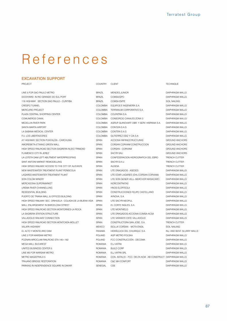
LINE 5 FOR SAO PAULO METRO BRAZIL MENDES JUNIOR DIAPHRAGM WALLS
DOCKYARD IN RIO GRANDE DO SUL PORT BRAZIL COMSA/GPO DIAPHRAGM WALLS
116 HIGHWAY . SECTION SAO PAULO - CURITIBA BRAZIL COMSA EMTE SOIL NAILING
CRESPO TUNNEL COLOMBIA EQUIPOS E INGENIERÍA S.A. DIAPHRAGM WALLS
MERCURIO PROJECT COLOMBIA TERRANUM CORPORATIVO S.A. DIAPHRAGM WALLS
PLAZA CENTRAL SHOPPING CENTER COLOMBIA COLPATRIA S.A. DIAPHRAGM WALLS
COMUNEROS CANAL COLOMBIA CONSORCIO CANALES ZONA 3 DIAPHRAGM WALLS
MEDELLIN RIVER PARK COLOMBIA AGRUP. GUINOVART OBR. Y SERV. HISPANIA S.A. DIAPHRAGM WALLS
SANTA MARTA AIRPORT COLOMBIA CONTEIN S.A.S. DIAPHRAGM WALLS
LA SABANA MEDICAL CENTER COLOMBIA CONTEIN S.A.S. DIAPHRAGM WALLS
F.U. LOS LIBERTADORES COLOMBIA GUTIERREZ DÍAZ Y CIA S.A DIAPHRAGM WALLS
A7 HIGHWAY. SECTION PUNTALON - CARCHUNA SPAIN ACCIONA INFRAESTRUCTURAS GROUND ANCHORS
AMOREBIETA-ETXANO GREEN WALL SPAIN CORSAN CORVIAM CONSTRUCCION GROUND ANCHORS
HIGH SPEED RAILROAD SECTION SAGRERA-NUDO TRINIDAD SPAIN CORSAN - CORVIAM GROUND ANCHORS
FLAMENCO CITY IN JEREZ SPAIN SACYR SAU GROUND ANCHORS
LA LOTETA DAM LEFT ABUTMENT WATERPROOFING SPAIN CONFEDERACION HIDROGRAFICA DEL EBRO TRENCH CUTTER
SANT ANTONI MARKET REMODELLING SPAIN SACYR S.A.U. TRENCH CUTTER
HIGH SPEED RAILWAY ACCESS TO THE CITY OF ALICANTE SPAIN ALDESA TRENCH CUTTER
NEW WASTEWATER TREATMENT PLANT PEÑISCOLA SPAIN UTE DRAGADOS - ASEDES DIAPHRAGM WALLS
LAGARES WASTEWATER TREATMENT PLANT SPAIN UTE EDAR LAGARES (OHL-CORSAN CORVIAM) DIAPHRAGM WALLS
SON COLOM WINERY SPAIN UTE SON GENER VELL- MERCHOR MASACARO DIAPHRAGM WALLS
MERCADONA SUPERMARKET SPAIN NORCONTRATAS DIAPHRAGM WALLS
UREMA RIVER CHANNELLING SPAIN HNOS ELORTEGUI DIAPHRAGM WALLS
RESIDENTIAL BUILDING SPAIN CONSTRUCCIONES FELIPE CASTELLANO DIAPHRAGM WALLS
PUERTO DE TRIANA MALL & OFFICES BUILDING SPAIN AYNOVA, S.A. DIAPHRAGM WALLS
HIGH SPEED RAILWAY. SEC. ORIHUELA - COLADA DE LA BUENA VIDA SPAIN UTE SACYR-NEOPUL DIAPHRAGM WALLS
MALL ENLARGEMENT IN BARCELONA STREET SPAIN EL CORTE INGLES, S.A. DIAPHRAGM WALLS
HIGH SPEED RAILROAD SECTION MONTORNES-LA ROCA SPAIN UTE MONTMELO DIAPHRAGM WALLS
LA SAGRERA STATION STRUCTURE SPAIN UTE DRAGADOS-ACCIONA-COMSA-ACSA DIAPHRAGM WALLS
VALLADOLID RAILWAY CONNECTION SPAIN UTE VARIANTE ESTE VALLADOLID DIAPHRAGM WALLS
HIGH SPEED RAILROAD SECTION MONTCADA-MOLLET SPAIN CONSTRUCTORA SAN JOSE, S.A. TRENCH CUTTER
XALAPA HIGHWAY MEXICO ISOLUX CORSAN – MOTA ENGIL SOIL NAILING
EL ALTO Y MONTELIRIO DAM PANAMA HIDRÁULICA DEL CHUIRIQUÍ, S.A. INJ. AND BENT. SLURRY WALLS
LINE 2 FOR WARSAW METRO POLAND AGP METRO POLSKA DIAPHRAGM WALLS
POZNAN-WROCLAW RAILROAD STA 145+162 POLAND FCC CONSTRUCCIÓN - DECOMA DIAPHRAGM WALLS
MEGA MALL BUCAREST ROMANIA ELJ VATRA DIAPHRAGM WALLS
UNITED BUSINESS CENTER 5 ROMANIA BUILD CORP DIAPHRAGM WALLS
LINE M5 FOR WARSAW METRO ROMANIA ELJ VATRA SRL DIAPHRAGM WALLS
METRO MAGISTRALA 5 ROMANIA CON. ASTALDI – FCC- DELTA ACM . AB CONSTRUCT DIAPHRAGM WALLS
TRAJANO BRIDGE RESTORATION ROMANIA C&C MH CONFORT DIAPHRAGM WALLS
PARKING IN INDEPENDENCE SQUARE IN DAKAR SENEGAL CDE DIAPHRAGM WALLS
EXCAVATION SUPPORT
88
R e f e r e n c e s
PROJECT COUNTRY CLIENT TECHNIQUE
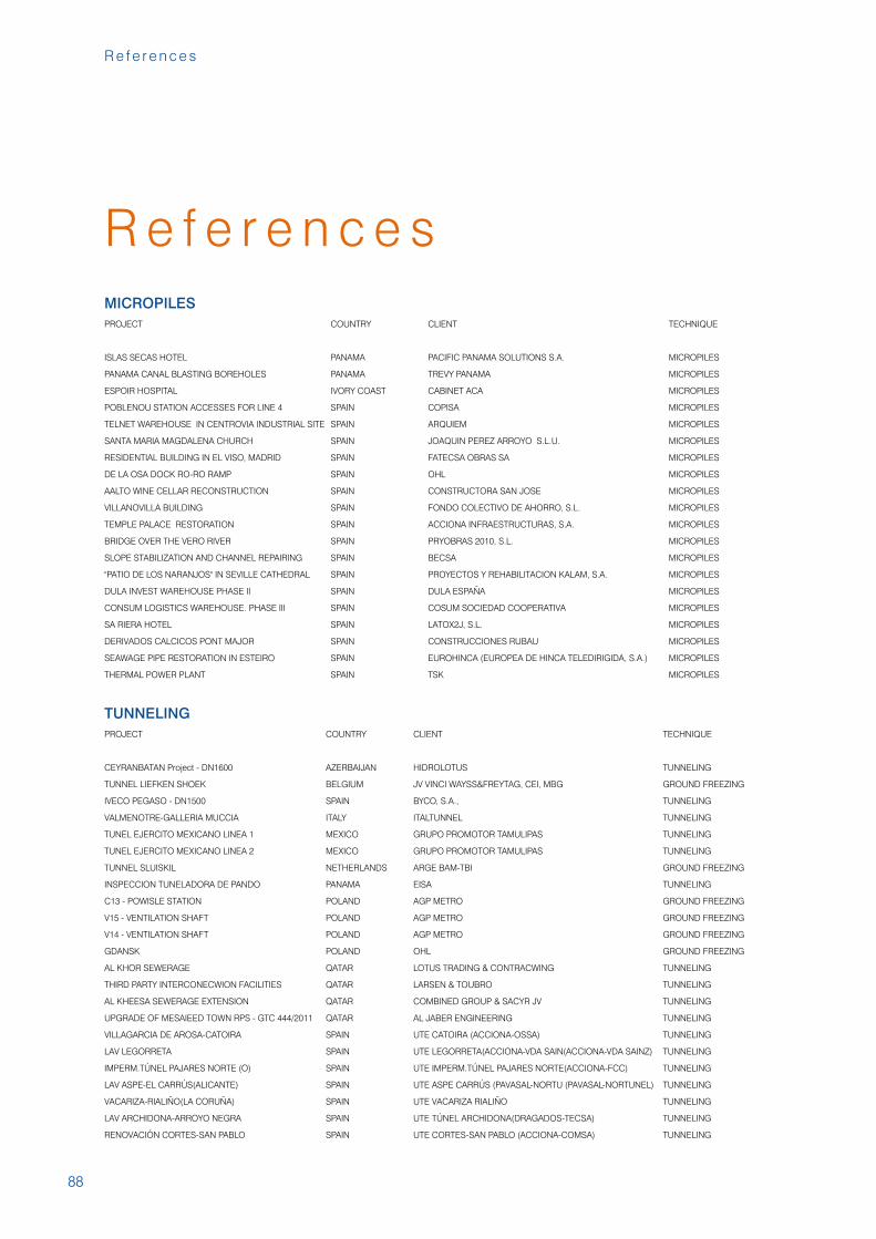
ISLAS SECAS HOTEL PANAMA PACIFIC PANAMA SOLUTIONS S.A. MICROPILES
PANAMA CANAL BLASTING BOREHOLES PANAMA TREVY PANAMA MICROPILES
ESPOIR HOSPITAL IVORY COAST CABINET ACA MICROPILES
POBLENOU STATION ACCESSES FOR LINE 4 SPAIN COPISA MICROPILES
TELNET WAREHOUSE IN CENTROVIA INDUSTRIAL SITE SPAIN ARQUIEM MICROPILES
SANTA MARIA MAGDALENA CHURCH SPAIN JOAQUIN PEREZ ARROYO S.L.U. MICROPILES
RESIDENTIAL BUILDING IN EL VISO, MADRID SPAIN FATECSA OBRAS SA MICROPILES
DE LA OSA DOCK RO-RO RAMP SPAIN OHL MICROPILES
AALTO WINE CELLAR RECONSTRUCTION SPAIN CONSTRUCTORA SAN JOSE MICROPILES
VILLANOVILLA BUILDING SPAIN FONDO COLECTIVO DE AHORRO, S.L. MICROPILES
TEMPLE PALACE RESTORATION SPAIN ACCIONA INFRAESTRUCTURAS, S.A. MICROPILES
BRIDGE OVER THE VERO RIVER SPAIN PRYOBRAS 2010, S.L. MICROPILES
SLOPE STABILIZATION AND CHANNEL REPAIRING SPAIN BECSA MICROPILES
"PATIO DE LOS NARANJOS" IN SEVILLE CATHEDRAL SPAIN PROYECTOS Y REHABILITACION KALAM, S.A. MICROPILES
DULA INVEST WAREHOUSE PHASE II SPAIN DULA ESPAÑA MICROPILES
CONSUM LOGISTICS WAREHOUSE. PHASE III SPAIN COSUM SOCIEDAD COOPERATIVA MICROPILES
SA RIERA HOTEL SPAIN LATOX2J, S.L. MICROPILES
DERIVADOS CALCICOS PONT MAJOR SPAIN CONSTRUCCIONES RUBAU MICROPILES
SEAWAGE PIPE RESTORATION IN ESTEIRO SPAIN EUROHINCA (EUROPEA DE HINCA TELEDIRIGIDA, S.A.) MICROPILES
THERMAL POWER PLANT SPAIN TSK MICROPILES
MICROPILES
PROJECT COUNTRY CLIENT TECHNIQUE
CEYRANBATAN Project - DN1600 AZERBAIJAN HIDROLOTUS TUNNELING
TUNNEL LIEFKEN SHOEK BELGIUM JV VINCI WAYSS&FREYTAG, CEI, MBG GROUND FREEZING
IVECO PEGASO - DN1500 SPAIN BYCO, S.A., TUNNELING
VALMENOTRE-GALLERIA MUCCIA ITALY ITALTUNNEL TUNNELING
TUNEL EJERCITO MEXICANO LINEA 1 MEXICO GRUPO PROMOTOR TAMULIPAS TUNNELING
TUNEL EJERCITO MEXICANO LINEA 2 MEXICO GRUPO PROMOTOR TAMULIPAS TUNNELING
TUNNEL SLUISKIL NETHERLANDS ARGE BAM-TBI GROUND FREEZING
INSPECCION TUNELADORA DE PANDO PANAMA EISA TUNNELING
C13 - POWISLE STATION POLAND AGP METRO GROUND FREEZING
V15 - VENTILATION SHAFT POLAND AGP METRO GROUND FREEZING
V14 - VENTILATION SHAFT POLAND AGP METRO GROUND FREEZING
GDANSK POLAND OHL GROUND FREEZING
AL KHOR SEWERAGE QATAR LOTUS TRADING & CONTRACWING TUNNELING
THIRD PARTY INTERCONECWION FACILITIES QATAR LARSEN & TOUBRO TUNNELING
AL KHEESA SEWERAGE EXTENSION QATAR COMBINED GROUP & SACYR JV TUNNELING
UPGRADE OF MESAIEED TOWN RPS - GTC 444/2011 QATAR AL JABER ENGINEERING TUNNELING
VILLAGARCIA DE AROSA-CATOIRA SPAIN UTE CATOIRA (ACCIONA-OSSA) TUNNELING
LAV LEGORRETA SPAIN UTE LEGORRETA(ACCIONA-VDA SAIN(ACCIONA-VDA SAINZ) TUNNELING
IMPERM.TÚNEL PAJARES NORTE (O) SPAIN UTE IMPERM.TÚNEL PAJARES NORTE(ACCIONA-FCC) TUNNELING
LAV ASPE-EL CARRÚS(ALICANTE) SPAIN UTE ASPE CARRÚS (PAVASAL-NORTU (PAVASAL-NORTUNEL) TUNNELING
VACARIZA-RIALIÑO(LA CORUÑA) SPAIN UTE VACARIZA RIALIÑO TUNNELING
LAV ARCHIDONA-ARROYO NEGRA SPAIN UTE TÚNEL ARCHIDONA(DRAGADOS-TECSA) TUNNELING
RENOVACIÓN CORTES-SAN PABLO SPAIN UTE CORTES-SAN PABLO (ACCIONA-COMSA) TUNNELING
TUNNELING
R e f e r e n c e s
89
Te r r a t e s t G r o u p
R e f e r e n c e s
PROJECT COUNTRY CLIENT TECHNIQUE
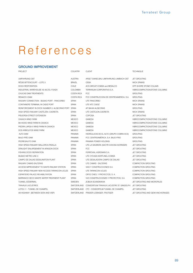
UMFAHRUNG OST AUSTRIA ARGE TUNNELBAU UMFAHRUNG LAMBACH OST JET GROUTING
RÉGIS BITTENCOURT – LOTE 3 BRAZIL OSSA WICK DRAINS
DOCK RESTORATION CHILE ACS GROUP, COMSA and BESALCO OFF-SHORE STONE COLUMS
INDUSTRIAL WAREHOUSE 45-48 ZOL FUNZA COLOMBIA TERRANUM CORPORATIVO S.A. VIBROCOMPACTION/STONE COLUMNS
CHUCAS DAM TREATMENTS COSTA RICA FCC GROUTING
RENACE II DAM COSTA RICA FCC CONSTRUCCION DE CENTROAMERICA, S.A. GROUTING
RAILWAY CONNECTION. BILBAO PORT - PANCORBO SPAIN UTE PANCORBO WICK DRAINS
CONTAINERS TERMINAL IN CADIZ PORT SPAIN UTE NTC CADIZ WICK DRAINS
REINFORCEMENT IN DOCK NUMBER 3. ALGECIRAS PORT SPAIN AP BAHIA ALGECIRAS GROUTING
HIGH SPEED RAILWAY CASTEJÓN- CADREITA. SPAIN UTE CASTEJON-CADREITA WICK DRAINS
PISUERGA STREET EXTENSION SPAIN COPCISA JET GROUTING
OAXACA WIND FARM MEXICO GAMESA VIBROCOMPACTION/STONE COLUMNS
BII-HIOXO WIND FARM IN OAXACA MEXICO GAMESA VIBROCOMPACTION/STONE COLUMNS
PIEDRA LARGA II WIND FARM IN OAXACA MEXICO GAMESA VIBROCOMPACTION/STONE COLUMNS
DOS ARBOLITOS WIND FARM MEXICO GAMESA VIBROCOMPACTION/STONE COLUMNS
ALTO DAM PANAMA HIDRÁULICAS DE EL ALTO (GRUPO COBRA-ACS) GROUTING
BAJO FRÍO DAM PANAMA FCC CENTROAMÉRICA, S.A. BAJO-FRIO GROUTING
PEDREGALITO DAM PANAMA PANAMA POWER HOLDING GROUTING
HIGH SPEED RAILWAY MALLORCA-PADILLA SPAIN UTE LA SAGRERA (SACYR-CAVOSA-SCRINSER) JET GROUTING
DRAUGHT ENLARGEMENT IN ARAGON DOCK SPAIN FCC JET GROUTING
FISHING DOCK REPARATION SPAIN FERROVIAL AGROMAN S.A. JET GROUTING
BILBAO METRO LINE 3 SPAIN UTE CYCASA-NORTUNEL-COMSA JET GROUTING
CAMPO DE DALIAS DESALINATION PLANT SPAIN UTE DESALADORA CAMPO DE DALIAS JET GROUTING
RAILWAY CAMAS-SALTERAS SPAIN UTE CAMAS - SALTERAS COMPACTION GROUTING
ACCESS IMPROVEMENT TO SANTS RAILWAY STATION SPAIN VIAS Y CONSTRUCCIONES S.A. COMPACTION GROUTING
HIGH SPEED RAILWAY NEW ACCESS TARANCON-UCLES SPAIN UTE TARANCON UCLES COMPACTION GROUTING
ESPARTERO PALACE REHABILITATION SPAIN ORTIZ CNES. Y PROYECTOS, S. A. COMPACTION GROUTING
BARRANCO SECO WASTE WATER TREATMENT PLANT SPAIN VVO CONSTRUCCIONES Y PROYECTOS, S.A. COMPACTION GROUTING
TUNNEL SÖDERMAL SWEDEN ZÜBLIN SCANDINAVIA JET GROUTING AND MICROPILES
TRAVAUX LACUSTRES SWITZERLAND CONSORTIUM TRAVAUX LACUSTRE ST. GINGOLPH JET GROUTING
LOT25.11 - TUNNEL DE CHAMPEL SWITZERLAND CTC - CONSORTIUM TUNNEL DE CHAMPEL JET GROUTING
A9 HIGHWAY (BETWEEN SION AND VISP) SWITZERLAND PRADER LOSINGER, FRUTIGER JET GROUTING AND GEWI ANCHORAGES
GROUND IMPROVEMENT

90
R e f e r e n c e s
PROJECT COUNTRY CLIENT TECHNIQUE
DEPÓSITO HIDROEÓLICO EL HIERRO SPAIN DEPÓSITO CENTRAL HIDROEÓLICAUTE WATER RESERVOIRS
BALSA TERMOSOLAR OLIVENZA SPAIN UTE TERMOSOLAR OLIVENZA WATER RESERVOIRS
BALSA CENTRAL TERMICA TERUEL SPAIN ENDESA GENERACIÓN WATER RESERVOIRS
BALSA LA CALDERETA SPAIN UTE BALSA LA CALDERETA WATER RESERVOIRS
IMP. BALSA PUENTENUEVO SPAIN EXCAVACIONES LEAL WATERPROOFING
BALSA BOADILLA DEL MONTE SPAIN SACYR WATER RESERVOIRS
IMP. BALSA ALLOZAR SPAIN MALLORCA CASTILLO DE VIÑUELAS WATERPROOFING
DIQUE DEL VASO DE SALINAS SPAIN POTASAS DE SUBIZA , S.A. (POSUSA) WATER RESERVOIRS
BALSA CERROJA SPAIN DIPUTACIÓN FORAL DE BIZKAIA WATER RESERVOIRS
NISSAN FACTORY SPAIN NISSAN FORKLIFT ESPAÑA , S.A SOIL DECONTAMINATION
TRANSFORM ENDESA SPAIN GRUPO SOLER SEALING AND DEGASSING OF LANDFILLS
PROY. OBRA SON REUS SPAIN EMAYA SEALING AND DEGASSING OF LANDFILLS
DEPOSITO SEGURIDAD III Y IV SPAIN TIRME SEALING AND DEGASSING OF LANDFILLS
SELLADO VERT CAL GITANET SPAIN UTE CAL GITANET SEALING AND DEGASSING OF LANDFILLS
VERTEDERO PUNTAL DEL BUHO ELCH SPAIN CLEOP, S.A. SEALING AND DEGASSING OF LANDFILLS
ENVIRONMENTAL WORKS
R e f e r e n c e s
Te r r a t e s t G r o u p
Juan de Arespacochaga y Felipe, 1228037 Madrid
Telf: +34 91 423 75 00Fax: +34 91 423 75 01
www.terratest.com
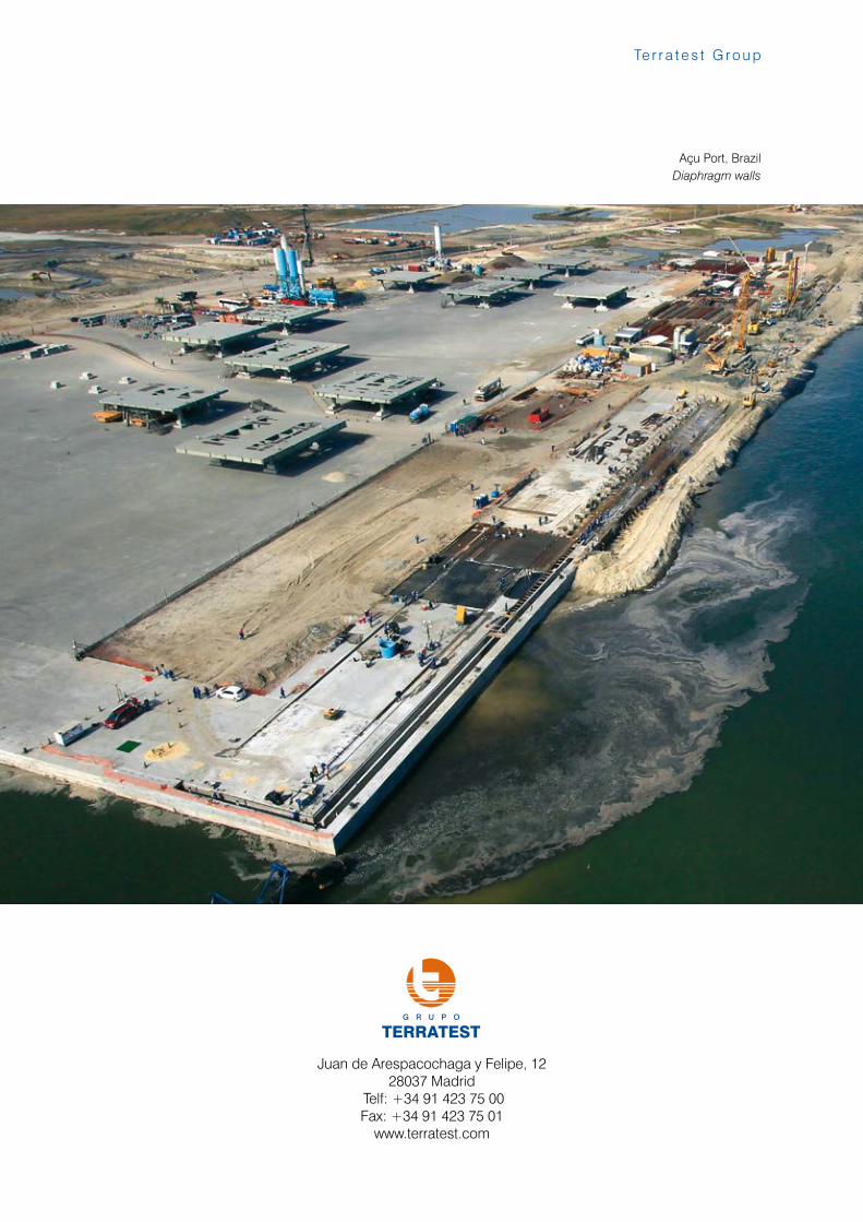
Açu Port, BrazilDiaphragm walls