trakcing systems with silicon with special reference to atlas-sct
DESCRIPTION
Some generalities about tracking Special requirements in LHC environments About silicon About the ATLAS-SCT. Trakcing systems with Silicon with special reference to ATLAS-SCT. Some general considerations. Tracking measures particle 3-momenta. Particle track. Sagitta, s. Lever arm, L. r. - PowerPoint PPT PresentationTRANSCRIPT

Trakcing systems with Siliconwith special reference to ATLAS-SCT
• Some generalities about tracking• Special requirements in LHC environments• About silicon • About the ATLAS-SCT
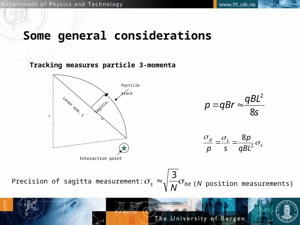
Some general considerations
s
qBLqBrp
8
2
ssp
qBL
p
sp
2
8
Tracking measures particle 3-momenta
Lever arm, L Sa
gitta
, s
r
Particle
track
Precision of sagitta measurement: hits N 3
Interaction point
(N position measurements)
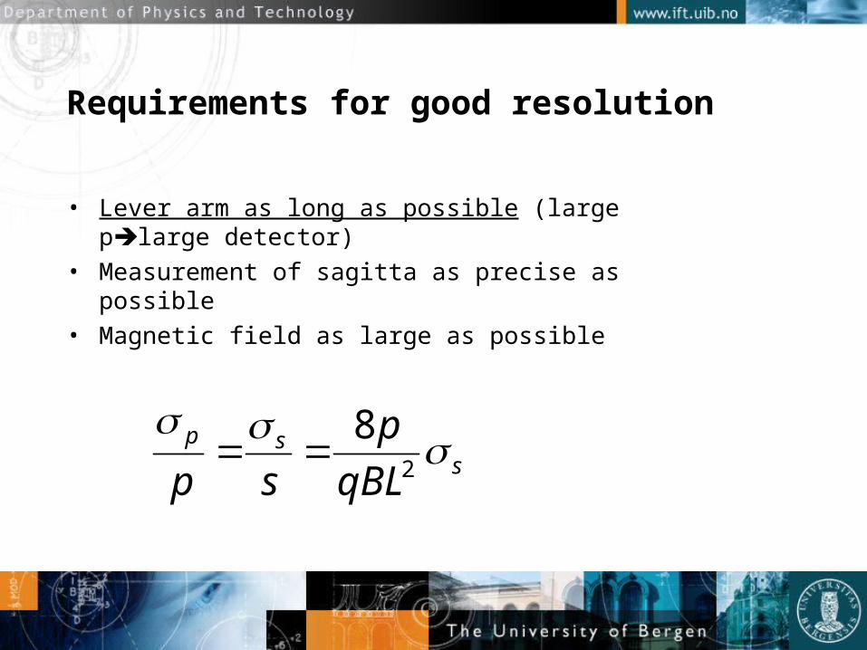
Requirements for good resolution
• Lever arm as long as possible (large plarge detector)
• Measurement of sagitta as precise as possible• Magnetic field as large as possible
ssp
qBL
p
sp
2
8

A ‘typical’ event Granularity is essential

Requirements to LHC tracker
• FAST (40MHz)• Excludes ‘standard’ Drift Chambers due to large drift times
• Spacial resolution a few tens of microns• High granularity• Radiation hard• Must minimize material
• Drift Chambers would be optimal from this point of view
• Silicon is a good choice

Does very precise tracking give very precise momentum estimates?
• Not necessarily due to Multiple (coulomb) scattering
• Direction change due to a concentrated scatterer:
msc
msc
Ls
XxXxcp
MeV
))/ln(038.0.1(/6.13
00
x/X0 is the amount of material traversedin units of radiation lengths

Example: Atlas SCT, 3% X0 /layer, and pixel measurements inside (probably also about 3% X0
per layer).
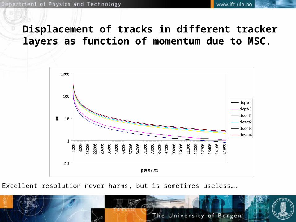
Displacement of tracks in different tracker layers as function of momentum due to MSC.
0.1
1
10
100
100010
00
8000
1500
0
2200
0
2900
0
3600
0
4300
0
5000
0
5700
0
6400
0
7100
0
7800
0
8500
0
9200
0
9900
0
1060
0
1130
0
1200
0
1270
0
1340
0
1410
0
1480
0
p(MeV/c)
um
dxpix2
dxpix3
dxsct1
dxsct2
dxsct3
dxsct4
Excellent resolution never harms, but is sometimes useless….

The silicon strips of the ATLAS-SCT has a pitch of 80 µm
• …. So position resolution is 23 µm per hit….
• Standard deviation of a flat distribution =width/(√12)
0
0.002
0.004
0.006
0.008
0.01
0.012
0.014
0.016
0.018
0.02-8
0
-74
-68
-62
-56
-50
-44
-38
-32
-26
-20
-14 -8 -2 4
10
16
22
28
34
40
46
52
58
64
70
76
P(x)
x
Uniform
Gauss

Basics of Silicon detectors
• ‘Simple’ p-n junctions• Reverse biased• Junctions can be segmented into strips
From L.G. Johansen, Thesis (Bergen)
~300um
thickness

Charge density
-12
-10
-8
-6
-4
-2
0
2
4
x
rho
Potential
0
2000
4000
6000
8000
10000
12000
x
'Vo
lts'
Electric field
-250
-200
-150
-100
-50
0
-23
-16 -9 -2 5 12 19 26 33 40 47 54 61 68 75 82 89 96
x
Fie
ld
A model for the diode: Constant charge density in the depletion region of the n-bulk, and heavily doped p-side
deN
xxEdx
dE
)(
2
2)( x
eNVx
eNxE
dx
dV dd
Nd is the donor concentration
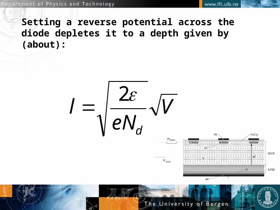
Setting a reverse potential across the diode depletes it to a depth given by (about):
VeN
ld
2

How to measure the depletion depth?
• Charge stored in bulk: (charge density x volume (Al))
• Capacitance:
VeNAVeN
AeNAleNQ dd
dd
22
VC
l
A
V
eNA
dV
dQlC d
2
1
1
2)(

The formula works!
20 detectors from Hamamatsu (L.G. Johansen, thesis)

Charge collection
• Typical detector thickness is 300 µm.• Bethe-Bloch equation + Landau fluctuations
gives a most probable energy loss of about 80keV
• To create a free electron-hole pair you need 3.6eV
Signal is about 22000 electrons ( 3.5 fC)
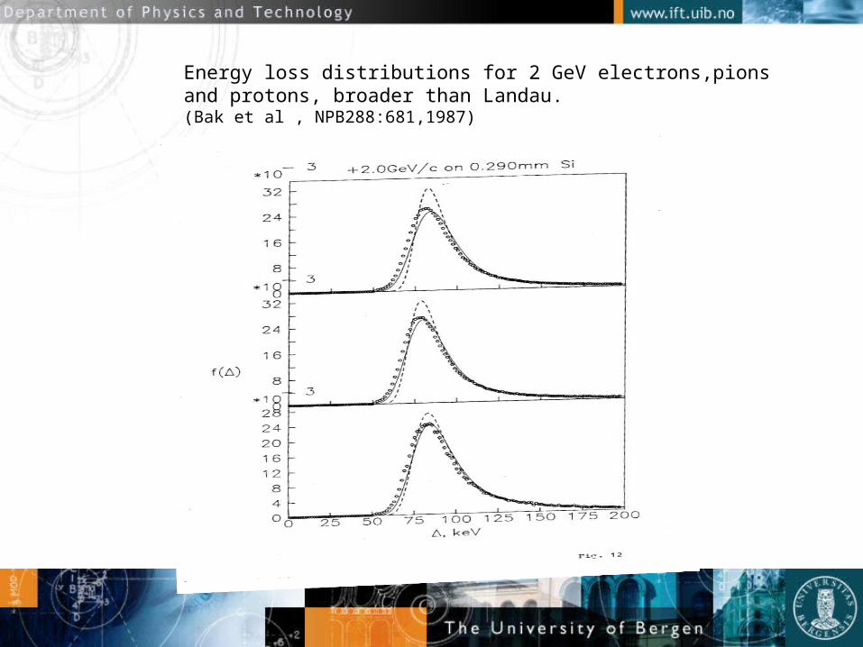
Energy loss distributions for 2 GeV electrons,pionsand protons, broader than Landau. (Bak et al , NPB288:681,1987)

The ATLAS SCT barrel detector
• Pitch 80 µm (resolution 23 µm)• 768 strips per detector• Thickness 285 µm• Size 6.36x6.40 cm2
• Should biassed to 350V• p strips on n material
Read-out electronics
• Must have low noise• Noise scales with capacitance Size limitations• microstrip detectors: inter-strip capacitances dominate.
• Must be compact ASICs• For ATLAS: Must operate at 25 Mhz• For ATLAS: Must be radiation tolerant
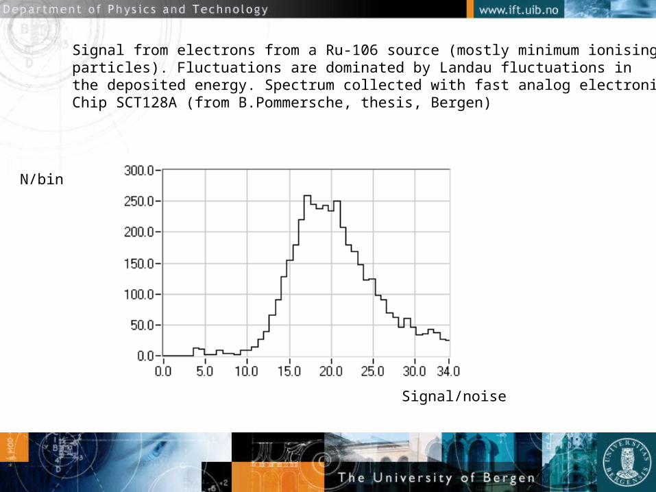
Signal from electrons from a Ru-106 source (mostly minimum ionisingparticles). Fluctuations are dominated by Landau fluctuations in the deposited energy. Spectrum collected with fast analog electronicsChip SCT128A (from B.Pommersche, thesis, Bergen)
N/bin
Signal/noise
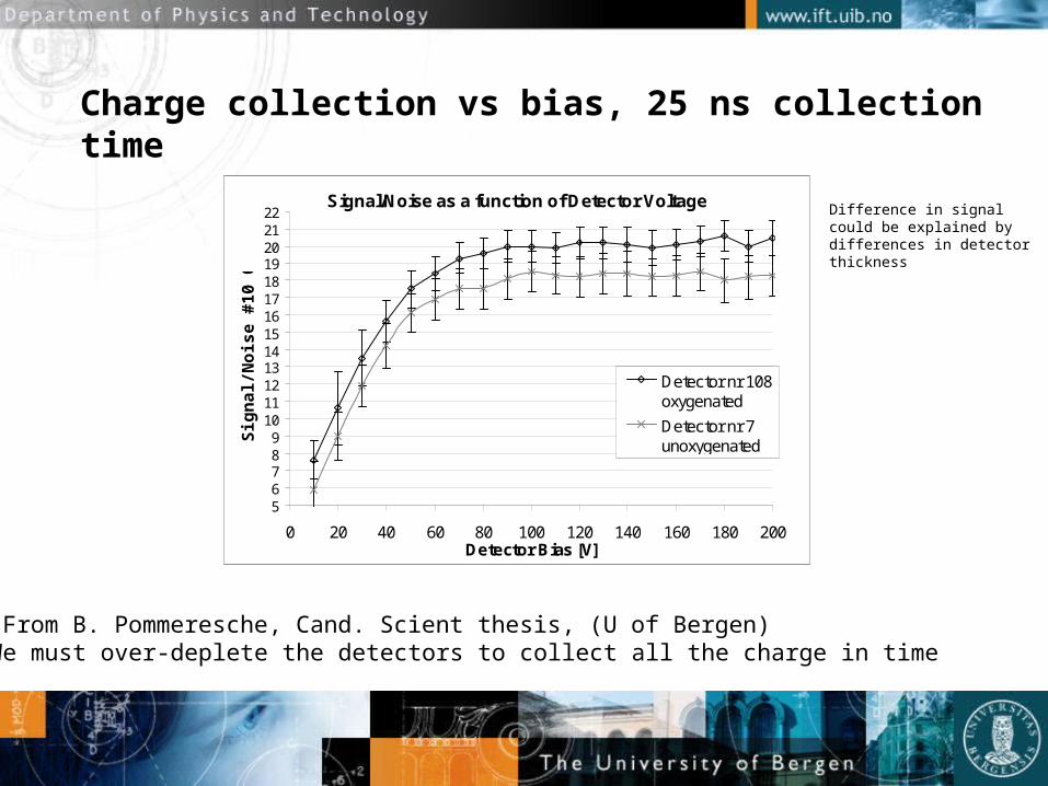
Charge collection vs bias, 25 ns collection time
Signal/Noise as a function of Detector Voltage
56789
10111213141516171819202122
0 20 40 60 80 100 120 140 160 180 200Detector Bias [V]
Sig
nal
/No
ise
#10
000
Detector nr 108oxygenated
Detector nr 7unoxygenated
From B. Pommeresche, Cand. Scient thesis, (U of Bergen)We must over-deplete the detectors to collect all the charge in time
Difference in signalcould be explained bydifferences in detectorthickness
What do we look for to assess the quality of a detector?
• Depletion voltage• Inter-strip capacitances
• Radiation hardnesswill require biassing to high volts
• Leakage currents must under control at high volts

The leakage current nightmare
• Current through the bulk: No problem• The Problem: Currents on detector surface, around
corners and who knows from where..….• High currents into the readout destroys the
electronics, to avoid it we take the following measures:• Capacitively (AC) coupled aluminium readout strips • Guard ring structures around active detector area (connect
to ground to suck out current)

The nightmare (part II)
• Large currents result in high power dissipation and heating of the detector system.
• Must be able to control the current, if not fully understood, it should at least be stable with time!
• Must test all detectors and detector modules for leakage current.
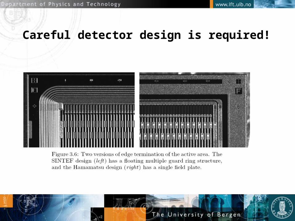
Careful detector design is required!

A detail of the detector for ATLAS-SCT
(picture from L.G. Johansen, thesis)

Leakage currents for some SCT detectors
(From L.G.Johansen, thesis (Bergen))

The detector modules must be radiation hard
• All components tested in a proton beam to a fluence of 3 x 10¹⁴ protons/cm2
• This is 50% more than expected for ten years of LHC operation
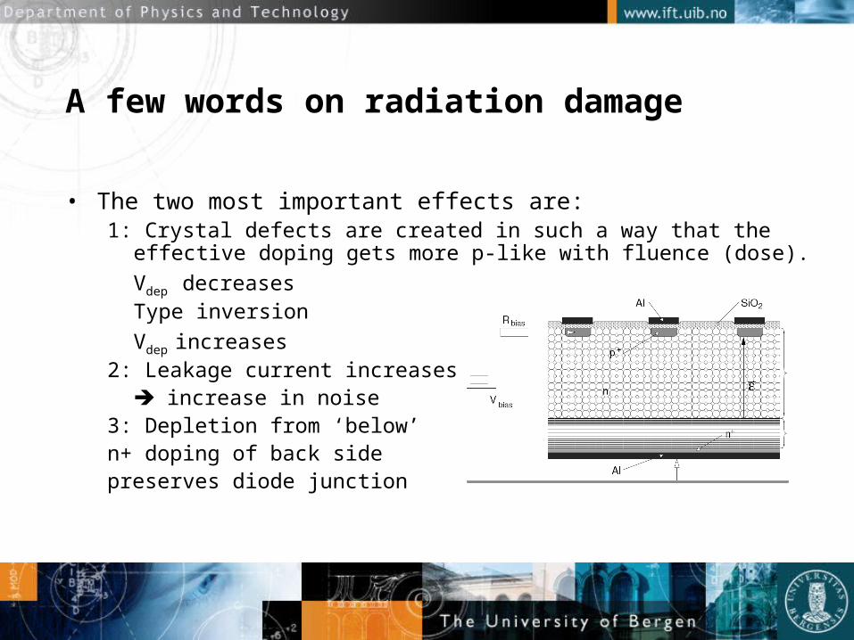
A few words on radiation damage
• The two most important effects are:1: Crystal defects are created in such a way that the effective
doping gets more p-like with fluence (dose). Vdep decreasesType inversionVdep increases
2: Leakage current increases increase in noise
3: Depletion from ‘below’n+ doping of back sidepreserves diode junction

Development of leakage current with time
L.G. Johansen, thesis

Signal/noise of an irradiated detector
Plot from L.G. Johansen (of course….)
Leakage current doubles for a temperature increase of 7 degrees
• ATLAS-SCT will be operated at about -10 degrees C
• Detector modules to be in thermal contact with cooling agent.

ATLAS-SCT readout electronics
• Digital readout (hit/no hit)• Pros and cons.of digital electronics
• Rad. Hard.• 128 readout channels per chip.
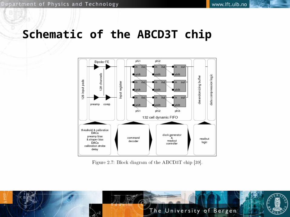
Schematic of the ABCD3T chip

The ALTAS SCT module

ATLAS-SCT barrel module
• 4 detectors• 1 baseboard (Patented TPG solution)
• Must be thermally conductive
• Hybrid with 12 chips, wraps around the sensor-baseboard.
• Strips are bonded together in pairs, to form 12 cm long strips.
• About 3000 wire bonds per module

A drawing of the module

Production of about 2000 modules at 4 university ‘clusters’ around the world
• Necessary for efficient use of small resources at each university.
• Production clusters:• Japan• US• UK• Scandinavia
Equipment needed or developed
• Cleanrooms• Tools for precision mounting (motorized jigs etc)• Microscopes• Metrology equipment (‘smart microscope’)• Bonding machines• Setups for electric tests

Module production
• Detector testing• Glueing of detectors to baseboard (5 um
precision)• Testing (IV), metrology• Hybrid testing and glueing • Bonding• Testing

To mount to 5 micron precision is not trivial!
midxf
0
5
10
15
20
25
30
35
40
-10.
50
-8.5
0
-6.5
0
-4.5
0
-2.5
0
-0.5
0
1.50
3.50
5.50
7.50
9.50
um
num
ber o
f mod
ules
midyf
0
5
10
15
20
25
30
35
40
45
-10.
5
-8.5
-6.5
-4.5
-2.5
-0.5 1.5
3.5
5.5
7.5
9.5
um
num
ber o
f mod
ules
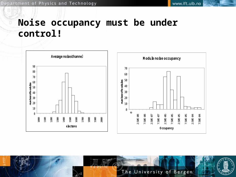
Noise occupancy must be under control!
Average noise/channel
0
10
20
30
40
50
60
70
80
90
1000
1100
1200
1300
1400
1500
1600
1700
1800
1900
2000
electrons
num
ber o
f mod
ules
Module noise occupancy
0
10
20
30
40
50
60
70
0
2.50
E-08
7.50
E-08
2.50
E-07
7.50
E-07
2.50
E-06
7.50
E-06
2.50
E-05
7.50
E-05
2.50
E-04
7.50
E-04
Occupancy
num
ber o
f mod
ules
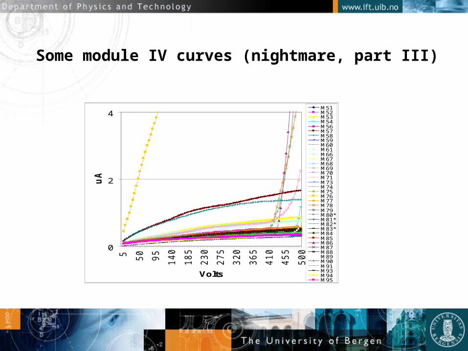
Some module IV curves (nightmare, part III)
0
2
45
50
95
14
0
18
5
23
0
27
5
32
0
36
5
41
0
45
5
50
0
Volts
uA
M51M52M53M54M56M57M58M59M60M61M66M67M68M69M70M71M73M74M75M76M77M78M79M80*M81*M82*M83*M84M85M86M87M88M89M90M91M93M94M95

But, in the end, the project seems to have been successful
• Yield factor OK (above 85 %)• Module mounting on barrels in Oxford• Transfer to CERN OK• Cosmic tests OK• Now, the barrel is in the ATLAS pit to be cabled
and tested further……


Conclusions
• Silicon tracking is very attractive in HEP• But not at all trivial to make….
• Very cost and manpower intensive…