training school vantage bowling training school. distributors 101 agenda:agenda: –8:00am coffee...
TRANSCRIPT

Vantage Bowling
Training SchoolTraining School

Distributors 101Distributors 101
• Agenda:Agenda:
– 8:00AM Coffee and Donuts
– 8:30AM Introductions
– 8:45AM Vantage Vision
– 9:30AM Tools & Safety
– 9:45AM Distributor Theory
– 10:15AM Break

Distributors 101Distributors 101
• Agenda:Agenda:
– 10:30AM Distributor Dis-Assembly and Inspection
– 12:00PM Lunch
– 12:30PM Distributor Repair and Assembly
– 1:45PM Break
– 2:00PM Distributor Adjustments
– 3:30PM Overview

Vantage BowlingVisions for the Future
Distributors 101Distributors 101
• Introduction:Introduction:
– Replacement of Parts• Inventory• Recommendations• Servicing• Billing
– Tools and Supplies• Inventory• Responsibility

Distributors 101Distributors 101
• Safety:Safety:
– When performing any kind of maintenance on a Pinspotter it is essential that you . . .
• 1) Disconnect the main power to the Machine
• 2) Wear safety glasses• 3) Lock out/Tag Out
– Vantage recommends following the safety procedures that are published in the Service Manuals which came with the Pin-Spotter

Distributors 101Distributors 101
• Tools Required:Tools Required:
– Combination Wrench Set (3/8 to 3/4)
– Deep Socket Set (3/8 to 3/4)
– Allen Wrench Set– Drive Punch Set– Crescent Wrench– Ball Peen Hammer– Snap Ring Pliers– Channel Locks– Spring Puller– Tape Measure
• Parts Required:Parts Required:

Distributors 101Distributors 101
• Theory:Theory:
– The Distributor is one of the subassemblies on the Pinspotter that can cause the most stops per frame when it is . . .
• Poorly Maintained• Maladjusted• Misunderstood
– A Distributor like its name “Distributes” Pins to the Bin Assembly. And, if not properly maintained can cause serious damage to the machine. Such as: (Broken Spotting Cups and Yoke Assemblies) which can be very costly.

Distributors 101Distributors 101
• Theory:Theory:
– Properly Maintaining a Distributor Assembly can eliminate machine stops which will increase the Frames per Stop.
– It is the Frames per Stop that is the Industry standard on how well the machines are being maintained and running while the Pin-Spotter is in operation.
– This class will cover the aspects of how to inspect, service, and build a Distributor Assembly.
– There are over 100 different part #’s that make up a Distributor Assembly and Vantage has every part needed to build a Distributor Assembly complete.

Removal
Distributors 101Distributors 101
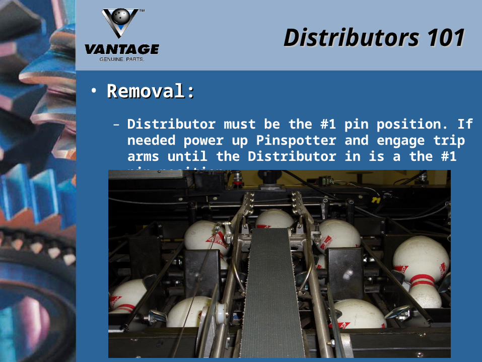
• Removal:Removal:
– Distributor must be the #1 pin position. If needed power up Pinspotter and engage trip arms until the Distributor in is a the #1 pin position.

Distributors 101Distributors 101
• Safety is # 1:Safety is # 1:
– Disconnect Power from Pinspotter
– Always remove main R-S Plug
– Lock Out / Tag Out
– Follow local OSHA requirements
– Tag Pinspotter “Out Of Service” at Front Counter

Distributors 101Distributors 101
• Removal:Removal:
– Distributor Height Adjustment
• Distributor Carriage Support Casting must be level with the Bin Assembly
EVEN

Distributors 101Distributors 101
• Removal:Removal:
– To achieve this add or subtract spacers to the Post Assembly
SPACERS
Distributors 101Distributors 101
• Removal:Removal:
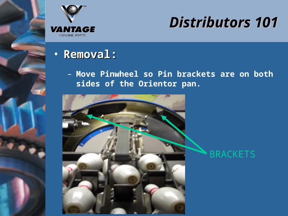
– Move Pinwheel so Pin brackets are on both sides of the Orientor pan.
BRACKETS

Distributors 101Distributors 101
• Removal:Removal:
– Distributor Drive Shaft Removal• Rotate Drive Pulley Shaft by pulling on the
Distributor Belt so that the roll pin can disconnect from U-Joint
ROLL PIN
DRIVE SHAFT

Distributors 101Distributors 101
• Removal:Removal:
– Distributor Drive Shaft Inspection• Shaft Straightness• Ball Bearing and Retainer Wear• Housing Grooved• U-Joint Wear and Leakage

Distributors 101Distributors 101
• Removal:Removal:
– Remove Rear Springs:

Distributors 101Distributors 101
• Removal:Removal:
– Slide Distributor Carriage all the way back and lift Distributor Assembly up and off Distributor Post

Distributors 101Distributors 101
• Test Bench:Test Bench:
– Vantage Recommends
– Each center have a rebuild station for the Distributor Assembly with a Motor and Gearbox set-up for bench testing the Distributor Assembly prior to installing the Distributor on the Pinspotter.
– This will allow each mechanic to make most adjustments prior to installation and then can fine tune the distributor on the Pinspotter.

Disassembly and Inspection

Distributors 101Distributors 101
• Disassembly and Inspection:Disassembly and Inspection:
– Belt Removal• Remove Tension Spring• Remove Lacing Pin• Pull Belt Through Assembly
– Belt Inspection• Cracks, Tears, Broken Lacings and Pins

Distributors 101Distributors 101
• Disassembly and Inspection:Disassembly and Inspection:
– Clutch Assembly
• Thrust Washer• Pinion Sleeve• Pinion Bushing• Pinion• Clutch Plate• Friction Disc• Washer• Worm Gear• Spring• Nut

Distributors 101Distributors 101
• Disassembly and Inspection:Disassembly and Inspection:
– Cam
• Warped• Broken Teeth• Flat Spots• Cracks

Distributors 101Distributors 101
• Disassembly and Inspection:Disassembly and Inspection:
– Connecting Link and Trip Rocker Arm
• Remove FlatHead Cap Screwand special nutfrom Top of the Link

Distributors 101Distributors 101
• Disassembly and Inspection:Disassembly and Inspection:
– Connecting Link and Trip Rocker Arm
• Remove Retaining Ring, Spring and Collar

Distributors 101Distributors 101
• Disassembly and Inspection:Disassembly and Inspection:
– Connecting Link and Trip Rocker Arm
• Slide Assembly from Casting

Distributors 101Distributors 101
• Disassembly and Inspection:Disassembly and Inspection:
– Connecting Link and Trip Rocker Arm
• Nylon Bushings• Retaining Ring• Tension Spring• Linkage

Distributors 101Distributors 101
• Disassembly and Inspection:Disassembly and Inspection:
– Arm Assembly
• Slide Arm away from Casting and inspect all Bearings

Distributors 101Distributors 101
• Disassembly and Inspection:Disassembly and Inspection:
– Drive Arm Assembly
• Special Bolt• Female Rod End• Spring Support• Safety Link• Cam Follower & Bearing• Drive Arm• Clamp Race

Distributors 101Distributors 101
• Disassembly and Inspection:Disassembly and Inspection:
– Trip Stop Rod Assembly Removal

Distributors 101Distributors 101
• Disassembly and Inspection:Disassembly and Inspection:
– Trip Stop Rod Assembly
• Rod Bent• Bearing Worn• Stop Blades

Distributors 101Distributors 101
• Disassembly and Inspection:Disassembly and Inspection:
– Trip Stop Support Bracket

Distributors 101Distributors 101
• Disassembly and Inspection:Disassembly and Inspection:
– Orientor Pan
• Cracked• Bent• Stops Dimension• 13 ¼”

Distributors 101Distributors 101
• Disassembly and Inspection:Disassembly and Inspection:
– Top Eccentric Bearings

Distributors 101Distributors 101
• Disassembly and Inspection:Disassembly and Inspection:
– Carriage Assembly
• Speed of the Carriage
• Final Distance of the Carriage
• Runs Free without Binding

Distributors 101Distributors 101
• Disassembly and Inspection:Disassembly and Inspection:
– Nylon Guide Pulley Assembly
• Replace all Bearing

Distributors 101Distributors 101
• Disassembly and Inspection:Disassembly and Inspection:
– Trip Arm Assemblies
• Roller Bearings
• Width and level of the Arms

Distributors 101Distributors 101
• Disassembly and Inspection:Disassembly and Inspection:
– Tubes, Belt Runners, and Guides
• Grooves

Distributors 101Distributors 101
• Disassembly and Inspection:Disassembly and Inspection:
– Right and Left Support Guides
Distributors 101Distributors 101
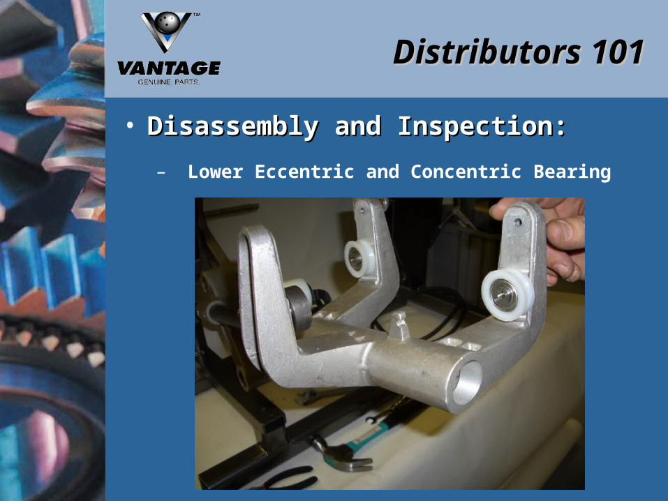
• Disassembly and Inspection:Disassembly and Inspection:
– Lower Eccentric and Concentric Bearing
Distributors 101Distributors 101
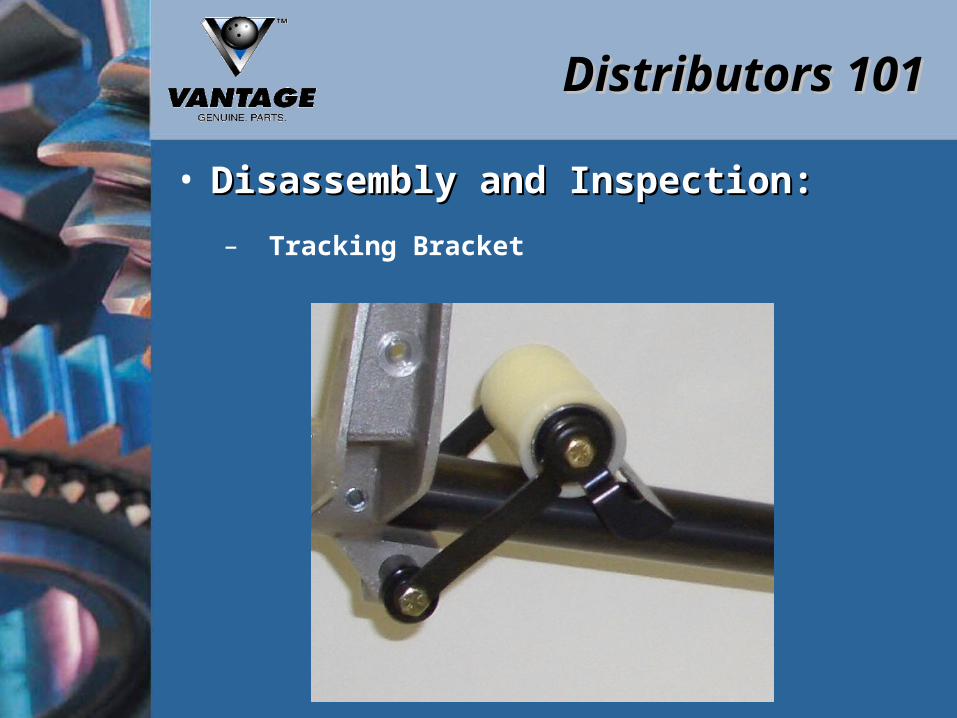
• Disassembly and Inspection:Disassembly and Inspection:
– Tracking Bracket

Distributors 101Distributors 101
• Disassembly and Inspection:Disassembly and Inspection:
– Drive Pulley

Distributors 101Distributors 101
• Disassembly and Inspection:Disassembly and Inspection:
– Main Casting and Bearing

Distributors 101Distributors 101
• Disassembly and Inspection:Disassembly and Inspection:
– Main Casting and Bearing
• If bearing removalis required turn castingover and remove capby tapping lightly
• Remove Snap Ringsand spacers and removebearings

Repair and Assembly

Distributors 101Distributors 101
• Repair and Assemble:Repair and Assemble:
– Main Casting and Bearing
• Replace needle bearingsall spacers and washersin main casting
• Secure with Snap Ring

Distributors 101Distributors 101
• Repair and Assemble:Repair and Assemble:
– Drive Pulley
– If there aren’t (2) ¼- 20 x 1 ¼ bolts in the middle of your orientor mounting holes, you need to put them in at this time.
– Hold pulley in place while sliding new shaft through to the left side.
– Replace Bracket if applicable, and Socket Head Cap Screw.

Distributors 101Distributors 101
• Repair and Assemble:Repair and Assemble:
– Drive Pulley

Distributors 101Distributors 101
• Repair and Assemble:Repair and Assemble:
– Tracking Bracket

Distributors 101Distributors 101
• Repair and Assemble:Repair and Assemble:
– Tracking Bracket
• Press Bearings
• Replace Bushings

Distributors 101Distributors 101
• Repair and Assemble:Repair and Assemble:
– Lower Eccentric and Concentric Bearing

Distributors 101Distributors 101
• Repair and Assemble:Repair and Assemble:
– Carriage Assembly
Distributors 101Distributors 101
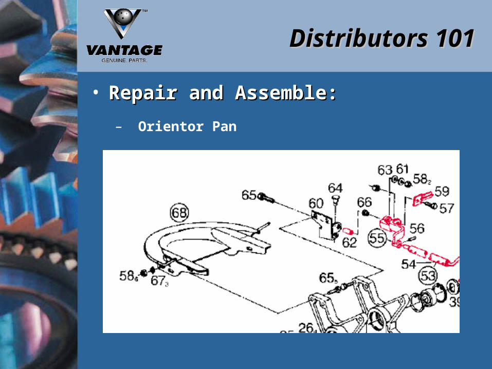
• Repair and Assemble:Repair and Assemble:
– Orientor Pan

Distributors 101Distributors 101
• Repair and Assemble:Repair and Assemble:
– Trip Stop Rod Assembly

Distributors 101Distributors 101
• Repair and Assemble:Repair and Assemble:
– Drive Arm Assembly

Distributors 101Distributors 101
• Repair and Assemble:Repair and Assemble:
– Arm Assembly

Distributors 101Distributors 101
• Repair and Assemble:Repair and Assemble:
– Connecting Link and Trip Rocker Arm

Distributors 101Distributors 101
• Repair and Assemble:Repair and Assemble:
– Cam

Distributors 101Distributors 101
• Repair and Assemble:Repair and Assemble:
– Clutch Assembly

Distributors 101Distributors 101
• Cam, Pinion, and Clutch Assembly:Cam, Pinion, and Clutch Assembly:
– Distributor must be aligned with the 1 pin bin and fully extended.
– Aligning the Pinion and Cam at 0 Degrees
– Three types of clutch’s
• Original Style• Super Clutch• Positive Indexing Distributor Brake

Distributors 101Distributors 101
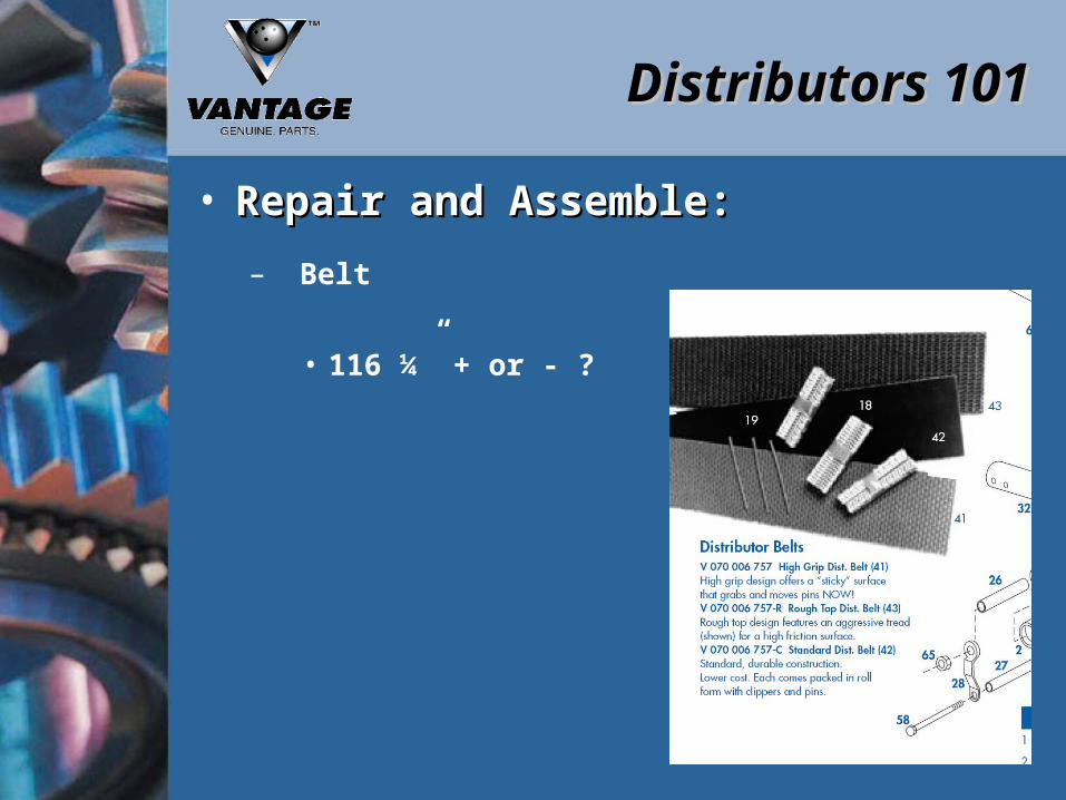
• Distributor Belts:Distributor Belts:
– Currently we know of at least 10 different styles of Distributor belts on the market today.
– We feel that it is a mechanics preference on which belt works best for them.
– Vantage offers 3 different styles of belt.• High Grip• Rough Top• Standard
– The main key to all the belts is the proper length of the belt. The thicker the belt the longer the belt needs to be to run correctly.
Distributors 101Distributors 101
• Repair and Assemble:Repair and Assemble:
– Belt
• 116 ¼” + or - ?
Maintenance and Adjustments

Distributors 101Distributors 101
• Maintenance and Adjustments:Maintenance and Adjustments:

Distributors 101Distributors 101
• Maintenance and Adjustments:Maintenance and Adjustments:
– Distributor Overview
– The distributor transfers pins from the elevator wheel to the bin assembly. The distributor is driven by an adjustable clutch through its various positions. The large nylon gear serves a dual purpose.
1. The outside of the gear contains a cam which moves the distributor to the various cup locations.
2. The other side of the cam controls the telescoping action of the front portion of the distributor. Springs keep the cam followers against the cams.

Distributors 101Distributors 101
• Maintenance and Adjustments:Maintenance and Adjustments:
– Timing Marks
– Clutch Spring
– Cam Follower
– Tension Spring

Distributors 101Distributors 101
• Maintenance and Adjustments:Maintenance and Adjustments:
– Distributor Replacement
1. Check level of the distributor mounting post. This should be level in both directions. If adjustment is needed, loosen the distributor bracket mounting bolts and position accordingly. Spacers are used between the distributor bracket and machine weldment to ensure will clear the bin assembly by at least 3/8”.
2. To replace the distributor drive assembly, do the removal procedure in reverse order.
3. Distributor Post Spacer V 070 006 143

Distributors 101Distributors 101
• Maintenance and Adjustments:Maintenance and Adjustments:
– Distributor Replacement
4. The clutch spring is to be set at one complete turn of the spring. The most difficult drive position is between the 6 and 10 pin feed positions.
a) If the spring tension is not strong enough, the distributor will stall between the 6 and 10 pin feed positions.
b) If too much tension is applied, it will cause stalling of the distributor or failure to index.
5. When the distributor is at the #1 bin position, the distance between the distributor orientor pan and the elevator wheel should be ¼” or less. If adjustment is necessary, loosen orientor pan attaching bolts and position accordingly.

Distributors 101Distributors 101
• Maintenance and Adjustments:Maintenance and Adjustments:
– Distributor Cam Operation
– The cam has a bump on each side of its outer edge at the base of the valley between the teeth. This locating mark and marked tooth of the pinion gear are to be matched for proper timing. The outer face of the large cam is marked for the feed position for each pin. The timing marks are in line only when the distributor is at the #1 bin position.
Note: If these conditions are not met, improper pin feed will result. The inside of the cam controls the telescoping of the distributor. The outside of the cam controls the movement to the various bin locations. The pin feed sequence is 1, 3, 2, 4, 7, 8, 5, 6, 10, 9.

Distributors 101Distributors 101
• Maintenance and Adjustments:Maintenance and Adjustments:
Distributors 101Distributors 101
• Maintenance and Adjustments:Maintenance and Adjustments:
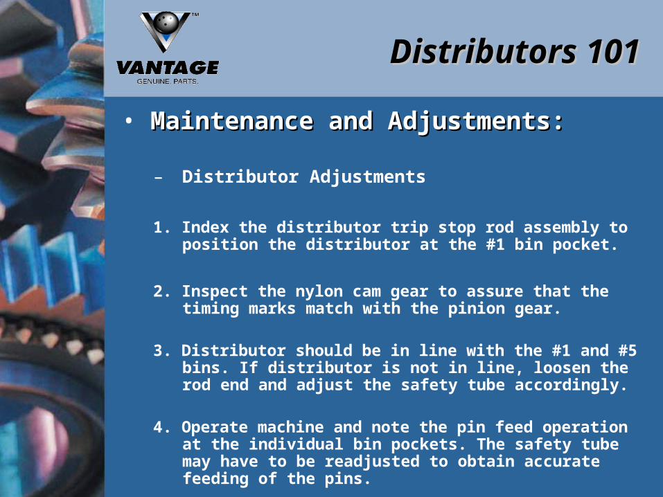
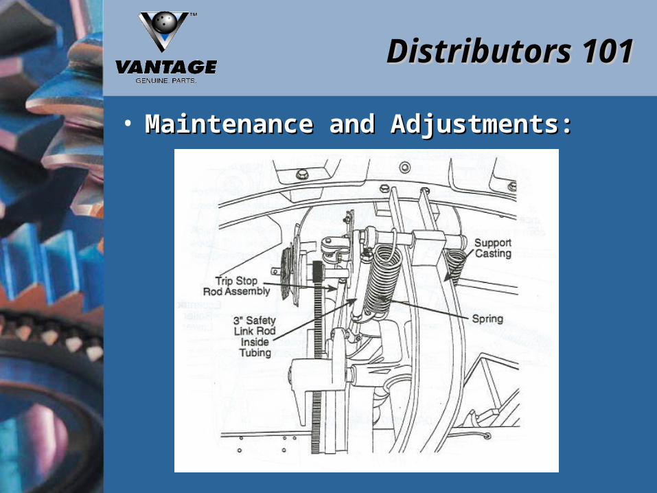
– Distributor Adjustments
1. Index the distributor trip stop rod assembly to position the distributor at the #1 bin pocket.
2. Inspect the nylon cam gear to assure that the timing marks match with the pinion gear.
3. Distributor should be in line with the #1 and #5 bins. If distributor is not in line, loosen the rod end and adjust the safety tube accordingly.
4. Operate machine and note the pin feed operation at the individual bin pockets. The safety tube may have to be readjusted to obtain accurate feeding of the pins.
Distributors 101Distributors 101
• Maintenance and Adjustments:Maintenance and Adjustments:

Distributors 101Distributors 101
• Maintenance and Adjustments:Maintenance and Adjustments:

Distributors 101Distributors 101
• Maintenance and Adjustments:Maintenance and Adjustments:
– Distributor Roller Adjustments
1. Starting with distributor at the #1 bin position, telescope so that it is at its’ minimum length.
2. Position the front lower eccentric roller in its’ lowest position, so the distance between the roller and the carriage tube is at its maximum.
3. Bring the top rear eccentric roller down until there is a noticeable drag against the carriage tube when you turn the roller.
4. Adjust the upper front eccentric roller until the trip rod tube and carriage tube are parallel to each other.

Distributors 101Distributors 101
• Maintenance and Adjustments:Maintenance and Adjustments:
– Distributor Roller Adjustments
5. Position the front lower eccentric roller up until it just makes contact with the carriage tube and are parallel to each other.
6. Adjust the cable so that the clearance between the nylon rollers and the trip rod tube is equal. This clearance is about 1/16” in all position of the distributor.

Distributors 101Distributors 101
• Maintenance and Adjustments:Maintenance and Adjustments:
Distributors 101Distributors 101
• Maintenance and Adjustments:Maintenance and Adjustments:
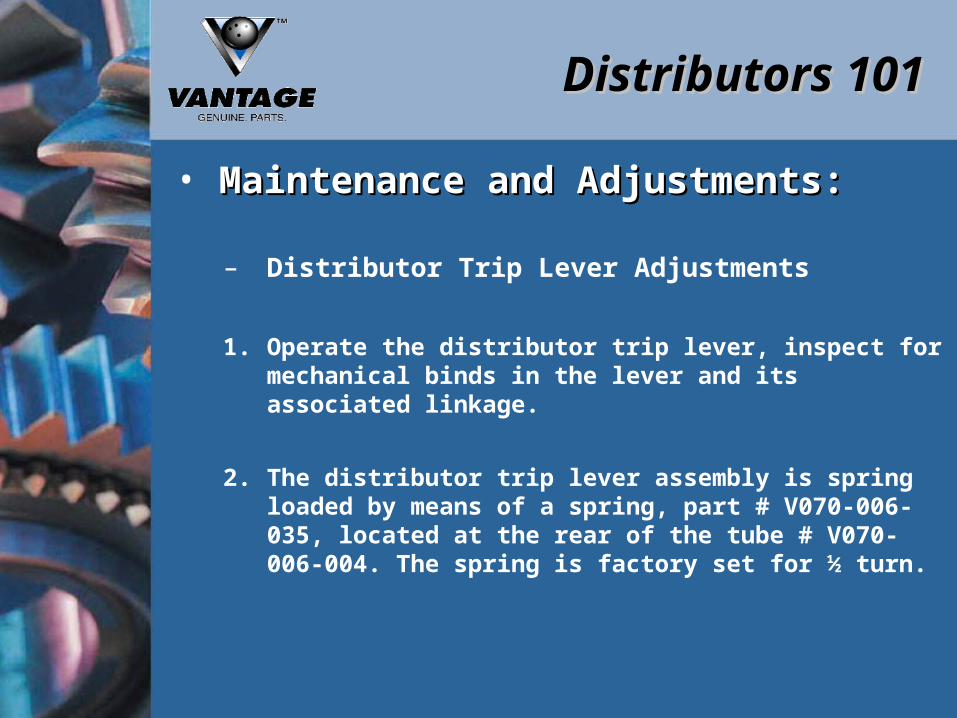
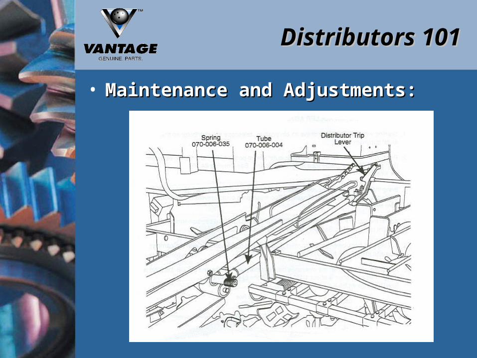
– Distributor Trip Lever Adjustments
1. Operate the distributor trip lever, inspect for mechanical binds in the lever and its associated linkage.
2. The distributor trip lever assembly is spring loaded by means of a spring, part # V070-006-035, located at the rear of the tube # V070-006-004. The spring is factory set for ½ turn.
Distributors 101Distributors 101
• Maintenance and Adjustments:Maintenance and Adjustments:

Questions?

Thank You