training outline hmls auto calcimeter
TRANSCRIPT

Training Outline Proper Use of the HMLS Auto Calcimeter
1

Table of Contents
Training Objectives 3
Introduction to Calcimetry 4-7
Overview of the HMLS Auto Calcimeter Kit 8-9
Instrument Checklist 10-12
Auto Calcimeter Setup 13-19
Software Setup 20-24
Sample Preparation and Test Setup 25-26
Testing Procedure 27-37
Saving and Loading Test Results 38-40
End of Test Procedure and Maintenance 41-42
Troubleshooting 43
2
Training Objectives
At the completion of the training course covered in this manual, the users should be knowledgeable regarding the following:
1. A basic introduction to calcimetry
2. How to properly setup the HMLS Auto Calcimeter for testing
3. How to properly prepare and load samples
4. How to use the software included in the HMLS Auto Calcimeter
5. How to properly run a sample test with the HMLS Auto Calcimeter
6. How to save and load test data
7. How to clean and maintain the HMLS Auto Calcimeter Kit and included instruments
3
Introduction to Calcimetry
What is Calcimetry?
Calcimetry is a method used to determine the amount of Calcium Carbonate (CACO3) and Magnesium Carbonate (Dolomite) in a sample of alkaline earth carbonates such as oil well cores or drilled cuttings.
4

Introduction to Calcimetry
Why is Calcimetry important?
Calcite build-up in drilling fluids and in water treatment processes causes scaling problems.
Data collected from calcimeters can help determine the proper chemical treatment.
5
Introduction to Calcimetry
ASTM Standard Testing Method for Calcimetry
1. Calcium carbonate and magnesium carbonate are reacted with 10% HCl in a sealed reaction cell to form CO2.
2. As the CO2 is released, the pressure build up is measured using either a pressure gauge or a pressure recorder.
3. During the calibration process, a calibration curve is created by reacting HCl with pure, reagent-grade CaCO3.
4. By using a known weight of CaCO3 reagent, you can determine the relationship between the amount of pressure released and the weight of CaCO3 in the sample.
5. Since all reaction cells are slightly different, this relationship will be different for each cell. Therefore, a calibration curve is required to obtain accurate results.
6. The calcium carbonate content of soil (ASTM Procedure D 4373) is determined by treating a 1g dried soil specimen with HCl in the reactor cell.
7. The resulting pressure increase is then measured and compared to the calibration curve to determine the total weight of CaCO3 in the test sample.
6
Introduction to Calcimetry
What does the HMLS Auto Calcimeter do?
1. The HMLS Auto Calcimeter provides fast, reliable data and is simple to use.
2. The HMLS Auto Calcimeter creates the calibration curve and automates the calculations necessary in calcimetry.
7

Overview of the HMLS Auto Calcimeter Kit
The HMLS Auto Calcimeter Kit comes with a variety of instruments used to perform the calcimeter tests.
Always go through a pre-test inventory check to make sure no instruments have been misplaced.
8
Overview HMLS Auto Calcimeter Kit
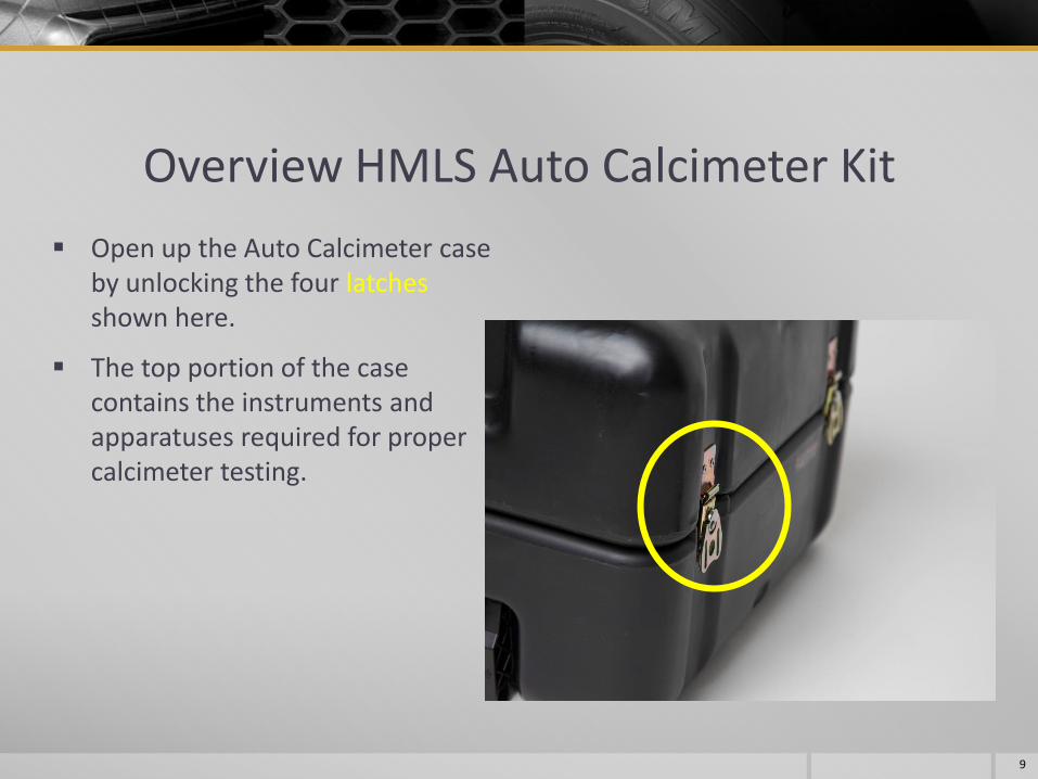
Open up the Auto Calcimeter case by unlocking the four latches shown here.
The top portion of the case contains the instruments and apparatuses required for proper calcimeter testing.
9

Instrument Checklist A. 110V Power cord
B. USB wireless PC keyboard-mouse
C. Reaction chamber
D. Reaction chamber stand (sits above the magnetic stirrer)
E. Reaction chamber screw-on top (ball valve assembly)
F. Mortar
G. 60 mL plastic syringes
H. Magnetic stirrer
I. Weighing scale (0.01g readability)
J. Pestle
K. Magnetic stir bar
L. ¼” Poly-tubing (with pre-fitted ½” NPT connector)
10

11
K

H D
G
J
C
E
12
K

Auto Calcimeter Setup Located in the battery compartment of the mouse is the USB wireless adapter.
Remove and connect the adapter to any of the available USB ports located to the right side of the screen. Turn the mouse on using the button located underneath.
13

Auto Calcimeter Setup Connect the 110V power cord (instrument A) and set the switch to the “ON” or ‘I”
position.
The display screen flips up from the unit and is unlocked by turning the locking pin counter-clockwise.
14

Auto Calcimeter Setup The HMLS Auto Calcimeter can be started by pressing the button located under
the screen on the plate.
15
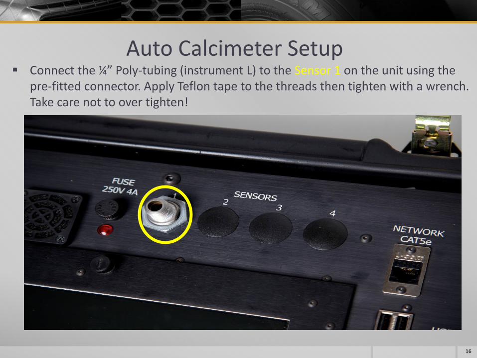
Auto Calcimeter Setup Connect the ¼” Poly-tubing (instrument L) to the Sensor 1 on the unit using the
pre-fitted connector. Apply Teflon tape to the threads then tighten with a wrench. Take care not to over tighten!
16

Auto Calcimeter Setup The other end of the poly-tubing connects directly onto the Reaction chamber screw-
on top (instrument E). The top comes with a pre-fitted black push-pull quick release type connector. Take the poly-tubing and push into the fitting. The poly-tubing can be released by pulling back on the front part of the fitting and pulling gently on the poly-tubing.
17
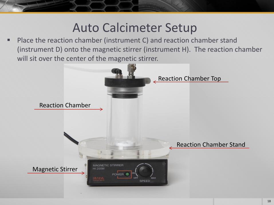
Auto Calcimeter Setup Place the reaction chamber (instrument C) and reaction chamber stand
(instrument D) onto the magnetic stirrer (instrument H). The reaction chamber will sit over the center of the magnetic stirrer.
Reaction Chamber
Magnetic Stirrer
Reaction Chamber Top
Reaction Chamber Stand
18

A Properly Configured Auto Calcimeter
19

Software Setup Turn on the HMLS Auto Calcimeter by pressing the button underneath the screen
plate (as seen on slide 15).
Once the PC has started, double click the HMLS Auto Calcimeter icon on the desktop.
20

Software Setup The first screen you see is called the Main Menu. The Menu Options (File, View,
Alarm…) can be toggled on and off by toggling the ESC key on your keyboard. Go ahead and toggle off the Menu Options.
21

Software Setup You may wish to change some of the default test parameters (although this is
optional). To do so, click the Utility Screen button while on the Main Menu.
22

Software Setup
23

Software Setup
24
Towards the bottom of the Utility Screen the user has three options as described below:
Pressure Loss Alarm Limit: Allows the user to set the threshold for the pressure loss alarm. For example, if the value is set to 0.5 (psi) and there is a loss of pressure in the system of 0.5 psi, the user is warned. We recommend this be set to 0.5 (psi).
Auto End 60 sec Pressure Diff. Limit: Allows the user to set a 60 second pressure differential to stop the test. For example, for a value of 0.5 (psi), if the HMLS Auto Calcimeter reads a pressure increase of less than 0.5 psi in a 60 second period, it will auto end the test. The check box to the right of the input field allows the user to enable/disable this feature.
Auto Timed End Time Limit: Allows the user to set the total test time, in minutes. The ASTM Standard requires a full 45 minute test, however in field tests you may require a significantly shorter test time. The check box to the right of the input field allows the user to enable/disable this feature.
Once the Utility Setup/Testing Parameters are set, click the
Main Menu button to return to the main menu.
Sample Preparation and Test Setup
25
1. Obtain a sample of core, drill cuttings, or other solids that are to be analyzed. The sample should be dry and free of contaminants. If you do not know whether the sample has been dried, heat it in an oven at 220°F (105°C) for 12 to 24 hours.
2. Using the mortar and pestle (instruments F and J), grind the sample fine enough to pass through the #100 mesh sieve supplied.
3. Plug in the main power cord for the weighing scale provided (instrument I). The scale comes with a measuring/dispensing tray. Place the measuring tray on the scale. Turn on and zero the scale.
4. Measure out 1.00 g ± 0.05 g of testing sample.
5. Carefully place the measured sample into the reaction chamber. You may find it easier to use a piece of paper to funnel the contents directly into the bottom of the chamber and not along the side walls.

Sample Preparation and Test Setup
6. Place the magnetic stir bar (instrument K) into the reaction chamber.
7. Take the reaction chamber top (instrument E) and hand tighten onto the reaction chamber by turning clockwise. Hand tighten only!
8. Connect the ¼’’ Poly-tubing (instrument L) to the black push-and-pull connector.
9. Locate the pressure release valve on the reaction chamber top, un-tighten (counterclockwise) and then retighten (clockwise). This will release any pressure build up for zeroing the sensors.
26
Magnetic stir bar
Reaction chamber
Pressure release valve
Push-and-pull connector with poly-tubing

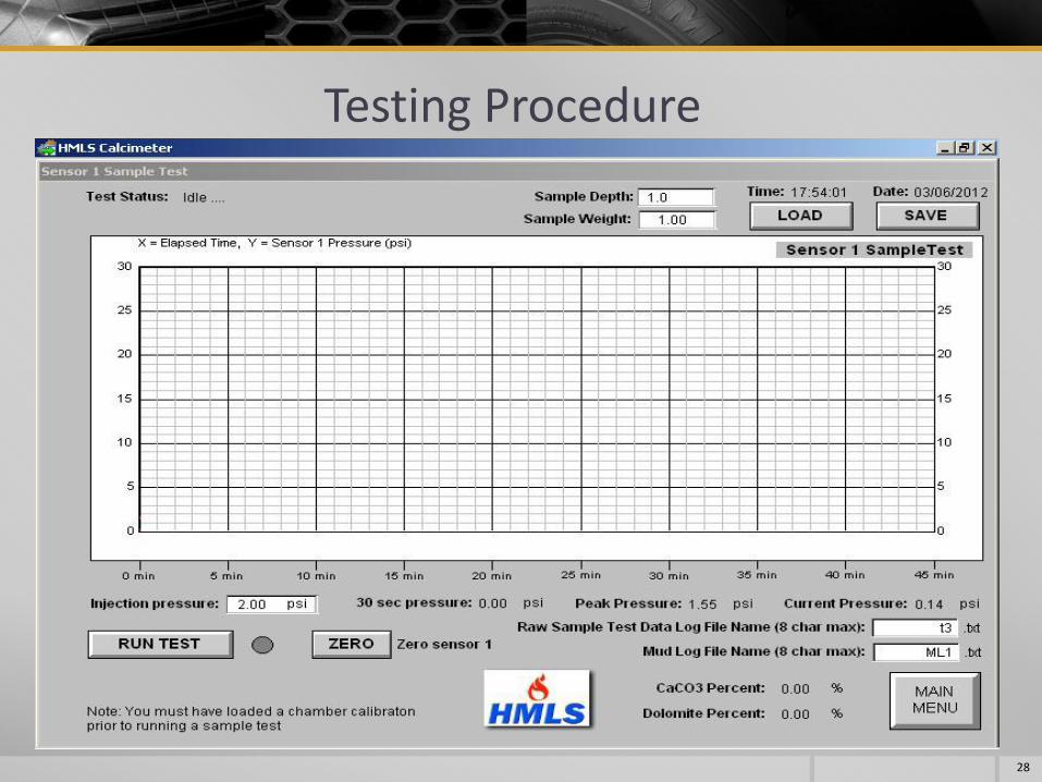
Testing Procedure 1. From the Main Menu, click the Sensor 1 Sample Test button.
27
Testing Procedure
28
Testing Procedure
2. The testing screen has fiver user input fields:
Sample Depth: Allows the user to input the depth from which the testing sample was taken. Input a number from 0 - 1,000,000 feet.
Sample Weight: Allows the user to input the weight of the sample. This should be 1.00 g ± 0.05 g.
Raw Sample Test Data Log File Name: Allows the user to enter the name of test file for the Raw Sample Test Data. (maximum of 8 characters).
Mud Log File Name: Allows the user to enter the name of Mud Log File. (maximum of 8 characters).
Injection Pressure: When using the injection method, the injection of 20 ml of Hydrochloric acid into the closed system causes an increase in pressure. To compensate for this, the user can input the value. We recommend this be set to 2.0 psi.
29

Testing Procedure
3. Once the user input fields have been filled, attach the male locking leur lock to the syringe (instrument G). The metal leur lock tightens onto the end of the syringe.
30
4. Fill the syringe with 20 ml of Hydrochloric Acid (10% v/v solution). Ensure that there are no air bubbles in the syringe.
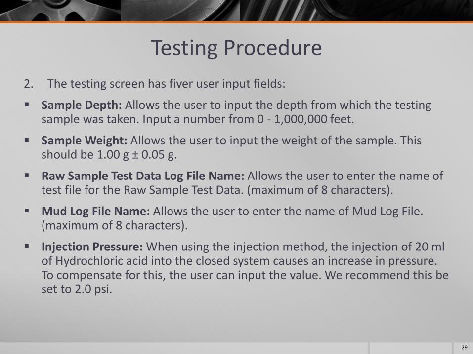
Testing Procedure 5. Carefully screw the syringe (with attached leur lock) onto the leur lock valve
found on the reaction chamber top (instrument E).
31
Leur lock valve

Testing Procedure 6. Ensure the leur lock valve is in the OPEN position.
32
Leur lock valve Open Leur lock valve Closed

Testing Procedure 7. Locate the pressure release valve (on the reaction chamber top – slide # 27), un-
tighten (counterclockwise) and then retighten (clockwise). This will release any pressure build up. The valve does not need to be completely unscrewed.
8. Click the ZERO button on the testing screen.
33
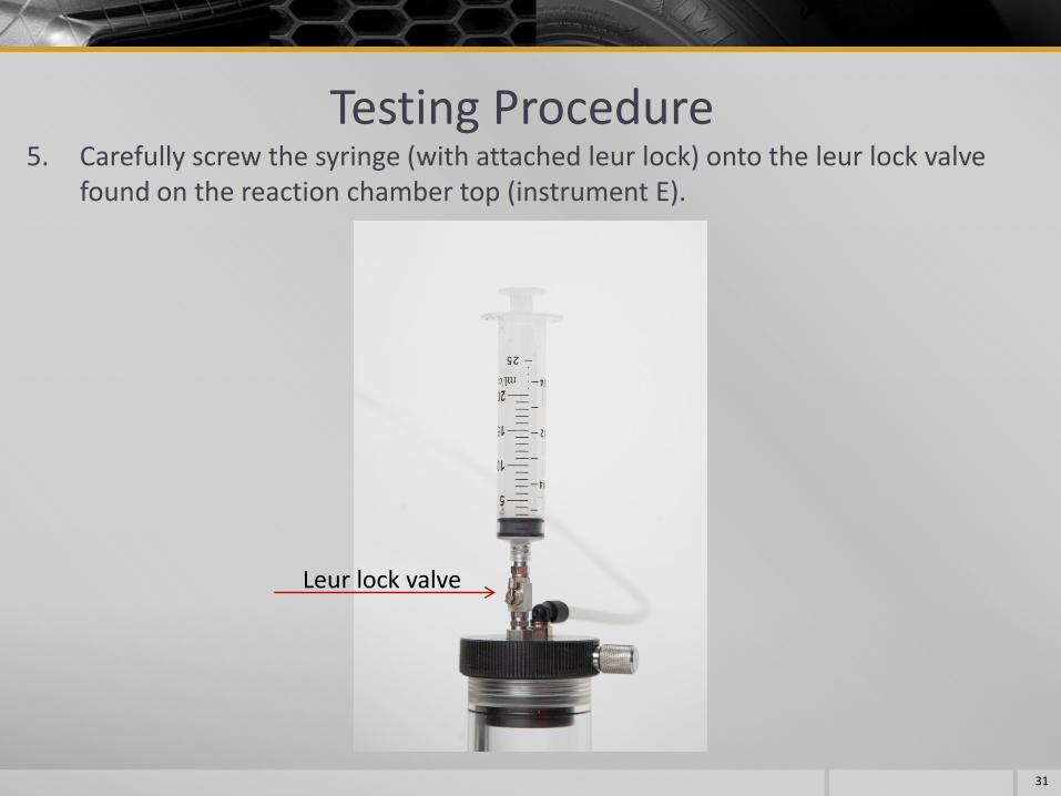
Testing Procedure 9. Turn on the magnetic stirrer (instrument H). Leave it on a slow speed.
Reaction Chamber
Magnetic Stirrer
Reaction Chamber Top
Reaction Chamber Stand
34

Testing Procedure 10. Click the RUN TEST button. Testing will not begin until there is a pressure
increase of 1.00 psi. This button will change to ABORT, and a green circle will appear next to the ABORT button (indicating a test in progress).
35

Testing Procedure 11. Push firmly down on the syringe. Once completely pressed, hold down firmly and close the
ball valve by turning it counter clockwise. This process requires the use of both hands-one to hold down the syringe and the other to close the ball valve.
12. Increase the speed of the magnetic stirrer. We recommend it be set to the fastest speed to ensure thorough mixing. The first 30 seconds of the test are the most important.
36
The HMLS Auto Calcimeter will run the test, as set up in the Utility Screen. The test can be aborted by clicking the ABORT button if required.
As the test proceeds, the graph will begin plotting the pressure against time (red line). Once the test has run the full 45 minutes or to either of the user enabled testing parameters, the software will calculate the percentage composition of calcium carbonate and dolomite.
The results can then be saved for viewing later. If the results are not saved, they will remain on the testing screen until another test is run.

Warnings Pressure Loss Warning: The Auto Calcimeter will warn the user if there is a pressure loss in the system. The pressure loss alarm limit is set in the Utility Screen (slide 23).
37
If you see the Pressure Loss Warning, check the following connections for leaks or loose connections:
i. Reaction chamber top and reaction chamber
ii. The pressure release valve on the reaction chamber top
iii. Black push-and-pull connector located on the top of the reaction chamber top
iv. Poly-tubing connection to Sensor

Saving and Loading Test Results
38
Once the test is completed, the test results can be saved by clicking the SAVE button. When clicked, a Windows dialog box will open to allow the user to enter a file name and hard drive location to save the results.
Previous test results can be viewed by clicking the LOAD button. When clicked, a Windows dialog box will open to allow the user to select a file to view. The file saved is a .rcp file which can be stored on the hard drive for later viewing.

Saving and Loading Test Results
39
The Raw Sample Data Log File and Mud Log file (named before beginning the test – shown here as t3 and ML1 respectively) are saved as text files on the hard drive. To view these files go to the following directories on the hard drive:
C:\HMLS\Calcimeter\Bore_Sample_Tests\Raw_Data
C:\HMLS\Calcimeter\Bore_Sample_Tests\Mud_Log

Saving and Loading Test Results
40
The Raw Data file is saved as a TAB delimited text file. It contains the following information:
Date
Time
Pressure
Chamber Label
Depth (sample depth)
The Mud Log file is also saved as a TAB delimited text file. It contains the following information:
Date
Time
Depth
CaCO3 %
Dolomite %

End of Test Procedure and Maintenance
The end of test procedure is very important!
The reaction between the testing sample and hydrochloric acid produces carbon dioxide gas. The pressure this gas creates as it is formed, along with the chamber containing hydrochloric acid, can pose a safety hazard. It is also very important to note that the acid is corrosive to metallic components. The stainless steel components will corrode and cause pressure leakage unless the following steps are undertaken.
We recommend using Dow Corning high vacuum grease on all seals to extend product life and ensure air tight seals for accurate testing. It is also recommended that all seals be inspected regularly and replaced when required to ensure safe and accurate testing.
The chamber top is made of Delrin plastic. It is very important you do not over tighten the fittings which connect to the chamber top. The top has been manufactured so that the fittings hand tighten (with at most a one-eighth turn with a wrench if required). Over tightening will shear the threads and the top will not hold pressure.
There is no need to remove the ball valve assembly or the black push-pull connector from the reaction chamber top unless replacing the Delrin top itself.
41

End of Test Procedure and Maintenance The end of test procedure is very important!
1. Once the test is complete, slowly release the pressure in the reaction chamber by turning the pressure release valve located on the reaction chamber top counterclockwise.
2. Disconnect the Poly-tubing from the reaction chamber top.
3. Flush the syringe and male locking leur lock with fresh water. It is used in the following steps to clean the ball valve-chamber top assembly
4. Unscrew the reaction chamber top with the ball valve assembly. There is no need to remove the ball valve assembly.
5. Wash the reaction chamber top assembly with fresh water. It is very important you flush the ball valve through with plenty of fresh water using the syringe.
6. Carefully remove the reaction chamber from the reaction chamber stand and dispose of the contents as per Weatherford standard operating and safety procedures.
7. Thoroughly wash and dry the reaction chamber and all components.
8. Carefully check all seals for wear and corrosion prior to testing or storage.
42
Troubleshooting
43
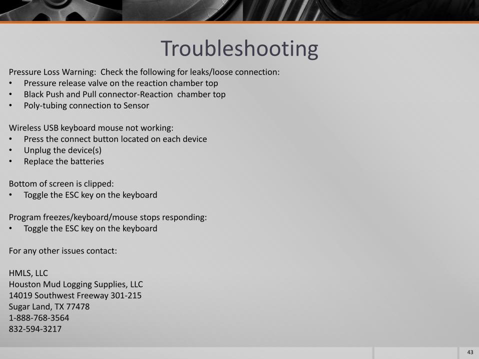
Pressure Loss Warning: Check the following for leaks/loose connection: • Pressure release valve on the reaction chamber top • Black Push and Pull connector-Reaction chamber top • Poly-tubing connection to Sensor Wireless USB keyboard mouse not working: • Press the connect button located on each device • Unplug the device(s) • Replace the batteries
Bottom of screen is clipped: • Toggle the ESC key on the keyboard
Program freezes/keyboard/mouse stops responding: • Toggle the ESC key on the keyboard For any other issues contact: HMLS, LLC Houston Mud Logging Supplies, LLC 14019 Southwest Freeway 301-215 Sugar Land, TX 77478 1-888-768-3564 832-594-3217