training module management in reduced impact logging ... · annex 2 fuel and lubricants issue sheet...
TRANSCRIPT

Training Module
Management in Reduced Impact Logging
Integral Module

© FORM International BV
2
PREFACE
The application of Reduced Impact Logging (RIL) techniques is one of the important requirements for the certification of sustainable forest management. However, considerable effort still has to be taken before the RIL practises will be operational on a large scale in the region. Previous experiences have already demonstrated the necessity and feasibility of the training in Reduced Impact Logging (RIL) techniques in the Congo Basin. Notwithstanding the considerable differences between the different countries of the Congo Basin we are of the opinion that by introducing the RIL practices in Gabon we can investigate at first hand the impacts of the conventional logging and demonstrate the advantages of RIL techniques for the enterprise and for the environment of all of central Africa. This because Gabon still accomodates a rich and very much varied patrimony of fauna and flora, which is not only like elsewhere, seriously threatened by the logging and mining industries and by the progressing demography, but also still very much susceptible to methods that might avert these threats. As the logging techniques in tropical countries can differ from country to country, and even from region to region and all the more as there are not yet sufficient data on RIL in Africa, it is still difficult to convince foresters of the advantages of the application of RIL. The RIL training courses aim at teaching logging staff and workers these specific techniques and to optimize their skills. The following modules have been composed to form a package of instruction covering most of the aspects of logging techniques under RIL methodology:
• Forest inventory and mapping • Road planning • Road construction • Controlled felling • Planning of skid tracks and tracing • Planned extraction • Log landing operations • Post-harvest operations • First aid in the forest • Management training in RIL
Hattem, the Netherlands, August 2010 Tieme Wanders Mans Vroom

© FORM International BV 3
1.1.1.1. CONTENTS PREFACE .......................................................................................................................................2 A. INTRODUCTION...............................................................................................................6 B. OBJECTIVES ....................................................................................................................7 C. TARGET GROUPS AND COMPETENCES TO BE TAUGHT ..........................................8
3.1 Target group 1 Specialists ....................................................................................................8 3.2 Target group 2 : Persons concerned ....................................................................................8
D. TRAINING PROGRAMME ................................................................................................9 4.1 General introduction and interpretation of the impact on the forest of the various logging operations and the RIL techniques to be applied .......................................................................9 4.2 Inventory ...............................................................................................................................9 4.3 Cartography..........................................................................................................................9 4.4 Road planning and construction ........................................................................................10 4.5 Controlled felling.................................................................................................................10 4.6 Extraction planning and techniques....................................................................................10 4.7 Log yard operations............................................................................................................11 4.8 Post-harvest operations......................................................................................................11 4.9 Schedule.............................................................................................................................11
GENERAL INTRODUCTION AND INTERPRETATION OF THE IMPACT ON THE FOREST OF THE VARIOUS LOGGING OPERATIONS AND THE RIL TECHNIQUES TO BE APPLIED........12 1. INVENTORY .............................................................................................................................13
1.1 Areas to exclude from harvesting .......................................................................................13 1.1.1 Opening lines and boundaries ....................................................................................13 1.1.2 Method ........................................................................................................................14 1.1.3 Techniques .................................................................................................................14 1.1.4 Counting (identification, position and measuring of trees) ..........................................15 1.1.5 Topographical characteristics .....................................................................................18 1.1.6 Health and Safety .......................................................................................................19
1.2 Mapping..............................................................................................................................20 1.2.1 Introduction and description........................................................................................20 1.2.2 The different types of maps used in RIL .....................................................................20 1.2.3 Basic Cartography for sustainability management......................................................26 1.2.4 Cartography of the Logging Inventory.........................................................................26 1.2.5 Cartography of road planning and construction ........................................................26 1.2.6 Cartography of the selection .......................................................................................26 1.2.7 Cartography of the felling............................................................................................26 1.2.8 Extraction cartography ................................................................................................27 1.2.9 Cartography of the post-harvest operations................................................................27 1.2.10 Summary of the maps...............................................................................................27
2. ROAD PLANNING AND CONSTRUCTION ..............................................................................28 2.1 Introduction, description......................................................................................................28 2.2 Classification and characteristics of the forest roads..........................................................28 2.3 Impacts to reduce and RIL techniques to anticipate during the planning ...........................33 2.4 Knowledge of the terrain.....................................................................................................33
2.4.1 Introduction .................................................................................................................33 2.4.2 Judgement of the conditions .......................................................................................34 2.4.3 Planning and tracing of the route ................................................................................35 2.4.4 Intensity of the road net ..............................................................................................35 2.4.5 Road net in relation to the skidding distance ..............................................................36 2.4.6 Knowledge of the road construction techniques .........................................................37
2.5 Drainage, bridges, culverts .................................................................................................39 2.5.1 Drainage .....................................................................................................................39

© FORM International BV 4
2.5.2 Pipes, culverts and enforced fords..............................................................................41 2.5.3 Bridges........................................................................................................................44 2.5.4 RIL ..............................................................................................................................49
3. CONTROLLED FELLING..........................................................................................................51 3.1 Introduction and interpretation of the impact of tree felling and the RIL techniques...........51
3.1.1 Introduction .................................................................................................................51 3.1.2 Safety prescriptions ....................................................................................................52 3.1.3 ”Kick-back” ..................................................................................................................53
3.2 Techniques of controlled felling ..........................................................................................53 3.2.1 Determination of the falling direction and opening of escape routes ..........................54
3.3 Bucking and crosscutting techniques .................................................................................55 3.3.1 Description and methods ............................................................................................55 3.3.2 Choice of places to crosscut .......................................................................................56 3.3.3 Crosscutting techniques..............................................................................................57 3.3.4 Safety measures .........................................................................................................58
3.4 Sharpening of the saw chain ..............................................................................................59 3.4.1 General conditions ......................................................................................................59 3.4.2 Hand sharpening tools ................................................................................................59 3.4.3 Maintenance of the chainsaw......................................................................................60
4. EXTRACTION PLANNING AND TECHNIQUES.......................................................................61 4.1Introduction and interpretation of the impact of the extraction.............................................61 4.2 Opening of skid trails ..........................................................................................................61 4.3 Engines used for extraction ................................................................................................62
4.3.2 Introduction, description..............................................................................................62 4.3.3 Track-type tractors CAT D6R and D7R.......................................................................63 4.3.4 Wheel skidders ...........................................................................................................63 4.3.4 Track-type skidder.......................................................................................................64 4.3.5 Engine log book ..........................................................................................................65
4.4 Planning, tracing and marking of the trails..........................................................................65 4.4.1 Introduction, description..............................................................................................65 4.4.2 Primary and secondary skidding.................................................................................66 4.4.3 Planning of the main trail.............................................................................................66 4.4.4 Tracing and opening of the main trail..........................................................................66
4.5 Tracking-and-clearing.........................................................................................................67 4.5.1 Introduction, description..............................................................................................67 4.5.2 RIL ..............................................................................................................................68 4.5.3 Techniques .................................................................................................................68 4.5.4 Hitching, choice between hook and choker.................................................................69
4.6 Skidding..............................................................................................................................71 4.6.1 Introduction and description........................................................................................71
4.7 RIL techniques....................................................................................................................72 4.7.1 At establishment of log yard........................................................................................72 4.7.2 At opening of skid trails ...............................................................................................72 4.7.3 At clearing ...................................................................................................................73 4.7.4 At skidding ..................................................................................................................73
4.8 Safety .................................................................................................................................74 5. LOG YARD OPERATIONS .......................................................................................................76
5.1 Introduction and interpretation of log yard operations and relevant RIL techniques...........76 5.2 The log yard........................................................................................................................77
5.2.1 Site and surface ..........................................................................................................77 5.2.2 Opening and drainage of the log yard.........................................................................78 5.2.3 Crosscutting ................................................................................................................78 5.2.4 Log treatment .............................................................................................................79 5.2.5 Handling of the logs ....................................................................................................80 5.2.6 Loading of logging trucks ............................................................................................81

© FORM International BV 5
5.2.7 Administration on the log yard.....................................................................................84 5.2.8 RIL and safety measures. ...........................................................................................86
6. POST-HARVEST OPERATIONS..............................................................................................88 6.1 Introduction and description................................................................................................88 6.2 Inspection of the inventory..................................................................................................88
6.2.1 Inspection of the road construction and waterworks ...................................................89 6.2.2 Inspection of tracking-and-clearing .............................................................................90 6.2.3 Felling check ...............................................................................................................91 6.2.4 Extraction inspection...................................................................................................92 6.2.5 Inspection of the log yard operations ..........................................................................93
7. OBSERVATIONS DURING THE TRAINING ............................................................................95 8. ABBREVIATIONS .....................................................................................................................99 9. SELECTED REFERENCES....................................................................................................100 ANNEX 1 CHECK-LIST ASSISTANCE TO MANAGEMENT IN RIL...........................................101 ANNEX 2 FUEL AND LUBRICANTS ISSUE SHEET..................................................................102 ANNEX 3 LOGGING REGISTER....................................................................................................1

© FORM International BV 6
A. INTRODUCTION
As all aspects of Reduced Impact Logging mentioned in the Preface are being treated separately and generally the Forest Manager is advised to take part in at least some of these trainings, he may lack the time to assist to all 10 of them. Therefore it is useful for him to assist at this training before choosing which specific training appeals most to his interests. Persons concerned, i.e. senior management staff, government officials (MINFOR, etcetera), researchers (universities), teachers (forestry schools), environmental NGO’s, are given the opportunity to get insight in the matters of sustainability of the forest production and environment. They can then also decide whether or not to pursue specific trainings, to let students follow these or to introduce them into environmental projects.

© FORM International BV 7
B. OBJECTIVES
This training also serves to broaden the perception of RIL of persons concerned, whether in connection with sustainable forest management and its certification or not. It treats all departments relatively superficially, but accentuates the environmental and cost-efficiency aspects. For other persons concerned, i.e. senior management staff, government officials, researchers, teachers, environmental NGO’s the objective is that they will be able to judge the importance of RIL as whether or not to introduce the trainings into their system, such as logging companies, forestry departments, universities, forestry schools and environmental projects.

© FORM International BV 8
C. TARGET GROUPS AND COMPETENCES TO BE TAUGHT
3.1 Target group 1 Specialists
Positions: Director of the Forest Department, Forest manager, certification manager.
Requested knowledge and competences : • Basic knowledge of cartography • Basic knowledge of the types and construction of the various forest
bridges, drains and culverts • Knowledge of the requirements for sustainable forest management and its
certification. • Competences to be taught : • In-depth knowledge of the principles and goals of RIL • Good understanding of the ecological effects on the forest by
conventional logging techniques • In-depth knowledge of the planning according to their importance to the
budgeted production in species and quantities • Knowledge of the capacities of each single operator and equipment • Fundamental knowledge of the techniques used in each department of
the logging operation. •
3.2 Target group 2 : Persons concerned
Positions : Management staff, government officials (MINFOR, etcetera), researchers (universities), teachers (forestry schools), environmental NGO’s Competences to be taught : • In-depth knowledge of the principles and goals of RIL • Good understanding of the ecological effects on the forest by
conventional logging techniques • In-depth knowledge of the planning according to their importance to the
budgeted production in species and quantities • Knowledge of the capacities of each single operator and equipment • Fundamental knowledge of the techniques used in each department of
the logging operation

© FORM International BV 9
D. TRAINING PROGRAMME
• The training module has been developed on the basis of the above mentioned requirements and consist of the following subjects that will be elaborated in Chapter 5 here below.
4.1 General introduction and interpretation of the impact on the forest of the various logging operations and the RIL techniques to be applied
• Elements : - Introduction, description - Impacts to be restricted and RIL techniques to anticipate during the
planning • Materials needed:
- Black board or flip-over with markers - Illustrations on posters or on Power Point
• Location: Meeting hall • Duration : Theory 3 hours • Personnel: 1 instructor
4.2 Inventory
• Elements : - Introduction, description - Impacts to be restricted and RIL techniques to anticipate during the planning • Materials needed: - Black board or flip-over with markers - All maps for Inventory as described in the module Cartography • Location: Meeting hall • Duration : Theory 6 hours, including Cartography. Feld: together with
Extraction • Personnel: 1 instructor
4.3 Cartography
• Elements : - Introduction - Description of the various types of maps - Methods, establishment, treatment and adaptation of the maps (by GIS or
by hand) • Materials needed: - Black board or flip-over with markers - Maps according to the cartography list of road planning - Computer with GIS software - Forestry maps, inventory maps • Location: Meeting hall • Duration : Theory: 1 hour during Inventory training • Personnel: 1 instructor
© FORM International BV 10
4.4 Road planning and construction
• Elements : - Introduction - Various types of engines and vehicles - Description of the various techniques (forest clearing, levelling, compacting) - Description of the various hydraulic constructions • Materials needed : - presence of the road construction engines - completed constructions • Location : - Planning : Meeting hall ; - Construction : Forest, at the road construction site (starting with the
uprooting) and along the completed trajectories. • Duration : Theory 4 hours. Field 2 hours • Personnel : 1 instructor
4.5 Controlled felling
• Elements : - Introduction - Description, maintenance of the chainsaw - Safety measures - Sharpening - Description of the controlled felling techniques - Bucking, crosscutting • Location : - Description, maintenance :workshop ; - Techniques : Forest, in a virgin compartment, distant from the production • Duration : 4 hours theory. Field: separate 6 days training Controlled Felling • Personnel : 1 instructor.
4.6 Extraction planning and techniques
• Elements : - Introduction - Various types of engines and vehicles - Description of the various techniques (forest clearing, levelling, compacting) - Description of the various hydraulic constructions • Materials needed : - presence of the road construction engines - completed constructions • Location : - Planning : Meeting hall ; - Techniques : Forest, starting at the log yard in operation and following the
engines during skidding. • Duration : Theory 4 hours. Field 12 hours (1 ½ day), including inventory • Personnel : 1 instructor.

© FORM International BV 11
4.7 Log yard operations
• Elements : - Introduction - Description of the various RIL and safety measures • Location : Forest, at the log yard • Duration : Theory 4 hours • Personnel : 1 instructor
4.8 Post-harvest operations
• Elements : - Introduction - Description of the various inspections and operations • Location : in the forest and at the log yard • Duration : Field 4 hours • Personnel : 1 instructor
4.9 Schedule
Subject Day 1 Day 2 Day 3 Day 4 Day 5
Introduction 3 hrs Inventory 5 hrs Cartography 1 hr Road planning and construction
4 hrs
Controlled felling 3 hrs Extraction planning and techniques
8 hrs 8 hrs
Log yard operations 4 hrs Post-harvest operations 2 hrs Evaluation of the training 2 hrs Total 8 hrs 8 hrs 8 hrs 8 hrs 8 hrs

© FORM International BV 12
GENERAL INTRODUCTION AND INTERPRETATION OF THE IMPACT ON THE FOREST OF THE VARIOUS LOGGING
OPERATIONS AND THE RIL TECHNIQUES TO BE APPLIED

© FORM International BV 13
1. INVENTORY
1.1 Areas to exclude from harvesting
There are various reasons to exclude areas from harvesting (often called buffer zones) such as: • Access (swamps, water ways, steep slopes, big rocks) to be determined
by the inventory team • Environmental protection (banks of water ways, mires, streams, habitat of
threatened species, high biodiversity area, High Conservation Value Forests, fragile habitats, etc.) to be determined by biologists working on the sustainable management plan
• Cultural value (cemeteries, sacred trees or forest) to be identified by sociologists working on the management plan
• Economic value (agricultural zones or areas reserved for use by villagers) to be determined by sociologists working on the sustainable management plan.
The areas have to be marked by staking out clear well marked lines in the forest and be positioned on the inventory map to be used during harvesting.
Figure 1 : Map showing the different levels mentioned in the text (compartment, block and inventory strips)
1.1.1 Opening lines and boundaries Introduction and description
Opening lines or line cutting means the staking out of terrain and it’s subdivision in plots by means of lines cut in the forest under growth. A new concession will first have to be marked in the field with a boundary line. The width and markings to be used are defined by the national forestry authorities. Where a boundary crosses a road this boundary also has to be marked with signs and clear colour markings.

© FORM International BV 14
Before the harvest inventory, the management inventory takes place (in the ideal situation). The inventory lines used for the management inventory do not correspond with those needed for the management inventory as it is only done at a fraction of the area (0,5 to 2%) Concessions are usually divided in annual harvesting areas, which are sometimes regrouped in five to six 5-year blocks thus covering a rotation of 25 to 30 years. The division of the concession is done based on information obtained through the management inventory, which indicates grossly where what species and volumes are to be found According to the criteria for sustainable harvesting the surface of an annual cutting area is obtained by dividing the surface of the concession by the number of years of the rotation. In Central Africa this rotation is normally 25 to 30 years.
1.1.2 Method The division of the concession in annual cutting areas is most often done in square or rectangular shapes of the same area. In hilly areas interspersed with outcrops and deep vales it is preferred to subdivide the terrain in harvesting pockets following natural features and trying to keep similar surfaces. It is however preferable to keep a system of square or rectangular shapes. The accuracy of inventory work done in irregular shapes has proven to be questionable. Lots of trees are not spotted. Also working with irregular shapes makes the mapping more difficult, especially if not GIS system is available. The most practical working method involved the cutting up of the annual harvesting compartment in rectangular blocks of the same size, except there where the boundary of the concession or the compartment interferes. This is often the case if the annual compartments have been determined using natural features such are rivers and streams. Examples are : • Squares of 1000 x 1000 metres = 100 ha • Squares of 2000 x 2000 metres = 400 ha • Rectangles of 500 x 2000 metres = 100 ha • Rectangles of 500 x 3000 metres = 150 ha • Rectangles of 1000 x 2000 metres = 200 ha, etcetera. Le choice is dictated by the size of the annual compartment, terrain characteristics and the number of workers to be implicated in the inventory. The following types of line can be distinguished: • Principal or base line, outlining the compartments • Counting lines directing the inventory workers during the inventory
1.1.3 Techniques • The line cutting team consists generally of 1 team leader, one compass
man, two chainers and 2 to 3 clearer (with cutlasses) • The base lines are usually oriented North-South and East-West
(magnetically for ease of working)

© FORM International BV 15
• Every 100 metres the compass man takes a bearing in the opposite direction (+ or - 180° degrees to the direction taken before) to verify the precise direction taken.
• The lines are opened to a width of 1 to two metres using cutlasses to remove the dense undergrowth. Poles are placed at regular intervals.
• Base lines should remain visible for at least two years • The line cutting team also marks the characteristics of the terrain (slope,
water courses, swamps) on the map. • The poles are placed every 50 or 100 metres and the distance from the
base point is written on them in industrial crayon or with a marker on ribbon.
• The clinometer is used to verify the slope and correct the distance between poles with
• The distance between poles is always measured at soil level and not in the middle or at the top of the pole as these are hardly ever planted exactly straight
• The GPS position is taken in the south-west corner of each inventory block
• Along paths through the blocks the number of the compartment and the block are written on trees in side the compartment bordering the path
• The production per team, depending on the terrain conditions, is about 2 kilometres per day.
Counting lines divide the block in inventory strips with a width of 100 to 200 metres. • It is advised not to distance the lines more than 100 metres apart to
assure a good positioning and communication between the prospectors and to assure the whole area is covered.
• The width of the lines should not be more than 1 metre • Along these lines poles should also be placed with the distances marked
on them. • The prospectors position themselves a equal distances on the base line
and advance in battle array while identifying and measuring the trees • They shout the species and size to the clerk who positions and notes the
trees on the map • Every so often the team has to align to assure working parallel to the
baseline • The production per team is , depending on the terrain circumstances,
about 3 to 4 kilometre per day (a strip of 100 metres thus means 30 to 40 hectares).
1.1.4 Counting (identification, position and measuring of trees) Introduction and description The criteria for the selection of trees for the inventory are : 1. Species 2. Classification (commercial, seed tree, protected species) 3. Minimum diameter (DBH) 4. Quality – shape of the trunk (straight, bent, twisted or hollow) 5. Position / accessibility in the terrain (slope, swamp etc.) The measurement of exploitable trees during the inventory allows the selection of trees with a diameter superior to the minimum authorised by law or determined in the management plan. It also allows identifying the future crop

© FORM International BV 16
trees. Finally, the inventory allows to estimate the volume of the trees (and thus per compartment) bases on volume tables which link volume to diameter (these tables are specific to certain forest areas). . Counting technique Counting technique : the counting team generally consist of 1 team leader and six (9) prospectors who cover a strip of 125 (200) metres wide. The ones on the left and the right walk on the line separating the counting blocks and hence need to cover only 12,5 metres. These are also responsible for the noting of distances on the poles and the alignment of the prospectors. The other members of the team each work a strip of 25 metre wide.
Numbering of the inventoried trees Only trees that are inventoried for harvesting in the current rotation are to be numbered. This inventory number has to be put n a clearly visible place preferable at eye height in paint, aluminium tags or in the bark with the scribing knife. Putting the number on a piece of ribbon to tie to the tree is not efficient as some animals (primates, elephants) will take the tape off and play with it. The numbered trees are listed in a book or in a table with Number – species –diameter.

© FORM International BV 17
Numbering the tree with paint and the scribing knife
Measuring technique The general rule in West and Central Africa is to measure the circumference of the tree at breast height (DBH), which is 1,30 metres of the ground or, in case of very pronounced buttresses, at 30 cm. above the buttresses.
Correct measuring at DBH and above buttresses Different notions : • The minimum harvesting diameter (MHD) per species is measured at
breast height and in case of buttresses at 30 cm above the buttresses. This diameter is determined by the national government and compulsory.
• The management diameter is determined based on the analysis of inventory data and species growth species and mortality rates. This diameter is determined by the management plan.
The tools normally used are • Aluminium callipers going to a diameter of maximally 1,50m. • The pi tape with two scales on in centimetres to measure the
circumference of a tree and one which converts the circumference in diameter.
• To measure above the buttresses a special board with a decimetre scale mounted on a pole exists. This allows a rough estimate of the diameter above the buttresses.
The height is measured preferably by sample, so more than one tree per DBH and not per single tree nor for all trees found.

© FORM International BV 18
Future crop trees having a DBH of over 50 cm. All trees of commercial species having a diameter at breast height of more than 50 cm are considered FCT and can be inventoried. Those positioned in the falling direction of harvestable trees are to be marked as such on the inventory sheet. These trees are later sought out before felling by the selection team and marked with a ribbon or with paint to enhance their visibility so fellers can avoid them during felling. Future crop trees which are found at less than 5 metres from planned skid trails also have to be marked by the selection team so they can be avoided during skidding Seed trees Seed trees are to be selected from the harvestable trees by the inventory team leader. These trees have to be of good health and form. They can be of a diameter slightly below the minimum harvesting diameter (MHD, MD) Trees of protected species Protected species are mentioned in the CITES list or in national legislation. In Africa the only tree on the CITES list is Kokrodua (Pericopsis Elata). This tree can not be harvested and exported from Ghana. In other countries it can be harvested and exported but only with the appropriate CITES documentation. Species that produce non-timber-forest-products (NTFP) will have to be spared during harvesting, though some species produce both NTFP’s and timber. When these species are found and villages are nearby, it has to be examined first whether harvesting these trees will negatively affect the communities. The analysis should be described in the management plan and an eventual compensation plan drawn up. Species protected nationally can be of any species which is judged rare or threatened. In most countries of Central Africa the Ebonies (Diospyros spp.) have been awarded a special status. These trees need to be marked on the inventory map, and before harvesting starts these have to be marked with tape or paint so they can be spotted and avoided.
1.1.5 Topographical characteristics Hydrology The line cutters, prospectors and clerks have to mark the following features accurately on their map : • Water courses crossing their line or strip, mentioning the width and the
direction of the flow • The state of the banks • In case of swamps the entire outline and the soil type (sandy, peaty) Soil The soil characteristics need to be identified and noted : sand, peat, clay, laterite, gravel stones, rocks. The presence of gravel and laterite is important for the construction and maintenance of roads. Peaty areas (mires) and rocky areas should be avoided during road construction. Slopes While opening the lines and during counting the slopes have to be measured with the clinometer and the distances corrected so the poles are placed at the correct distance from the baseline.

© FORM International BV 19
On the inventory sheet the slope are mentioned with an arrow indicating up-slope: • > = slight incline, no need to level off slopes or to cut out flank roads • >> = steep slope, necessary to level off or to cut roads into the slope • >>> = impassable slope, to be avoided Vegetation Changes in the type of vegetation are to be noted on the inventory sheets. Distinctions can be made between: • Dense forest with little undergrowth • Dense forest with dense undergrowth • Light forest • Forest with big gaps or openings • Tree savannah • Savannah • Plantations • Agricultural land / fallow • Bare earth. rock
1.1.6 Health and Safety Safety
The inventory team is subject to diverse risks and dangers while staying in the forest day and night. Several safety rule are to be respected to increase safety : • When choosing for the placement of the camp observations of the terrain
have to be made of especially the canopy to spot any overhanging dead branches that may fall
• The camp has to be site sufficiently far from streams to avoid the risk of flooding which could cut people off from food and equipment
• Water from streams is not to be drunk unless clean and clear. It is however always best to filter and boil water from streams
• The soil of the camp, especially below and surround the beds, tarpaulins and tents has to be cleaned of all rubbish or vegetation which could attract and hide vermin or other harmful animals (ants, rodents or snakes)
• When there is an indication of the presence of big game (such as elephants, buffalos or gorillas the team has to turn back and wait until the animals move away
Health
• Every team needs to have a first aid kit which contains material for the treatment of pains, cuts, stings, bites and the stabilisation of broken bones. It should also contain medicines for the treatment of malaria, diarrhoea and fever.
• Every team has to have members trained in the application of first aid. This training and a procedure for emergencies assure people know how to react in an emergency, and how the immediate evacuation is to be done in case of need.
• Teams should have a satellite phone or radio to be used in emergencies. • Toilets should be dug sufficiently far from streams to avoid pollution and
be deep enough to avoid flooding in case of heavy rain. • The toilets have to be filled with earth when camp is abandoned. • If toilets are not dug, any excrement has to be immediately buried
sufficiently deeply.

© FORM International BV 20
• Bodily hygiene is just is very important when living in the forest. A good spot has to be chosen so there is access to clean water for washing near the camp.
1.2 Mapping
1.2.1 Introduction and description As the cartography is the only means of which the forest manager disposes to combine the data of the terrain and the inventory and to trace the roads before going on the ground, it can never be complete enough. Apart from the planning of roads and skid trails, he needs access to all inventory data. The maps are numbered I to XV and described in sequence. Next the various operations are quoted with the specific and elaborated required maps. Finally all the maps are summarized in a table.
1.2.2 The different types of maps used in RIL Map I. National map of Forest Concessions under Sustainable Management
Handed out by the Ministry of Forestry, featuring: • Topography • Hydrography • Road network • Waterways network The national map of forest concessions allows the forester to identify the boundaries of his concessions with his neighbours, the infrastructure of the country (roads, railways, waterways) and the position of their mutual work areas and in relation to the destination of his products (factory, harbour). It also allows him to plan the procurement of other concessions and to plan at long term the production programme of his enterprise.
Map II. Management map of the Concession under Sustainable Management (CSM) Scale 1/200.000, format A2, NIC or LANDSAT, featuring: • Boundaries of the concession, the FMU’s and their quenquennial plans • Other management series (protection and conservation, agro-forestry) • Human settlements • Topography • Hydrography • Contour lines (or isohypse lines) or • Images of the relief The map of the Concession under Sustainable Management (CSM) displays the exact boundaries, according to the readings indicated in the official allocation by the Forestry Ministry. This very map serves for the location of the Forest Management Units (FMU) and the Quenquennial Units (QU). Featuring the boundaries of the FMU, this map serves as base for the establishment of the planning of the Sustainable Management Inventory (sample survey planning, etcetera), next the subdivision in Quenquennial unit and finally the subdivision of these QU in Annual Coupes (AAC) consisting each of 1/25 or 1/30 of the surface of the FMU. The provisory planning of the access roads and main roads can also already be made in this stage with the help of this map.

© FORM International BV 21
Map III. Map of the FMU and its QU
Scale 1/50.000, format A2, NIC or LANDSAT maps, featuring: • Boundaries of the FMU and its QU • Existing and planned roads and constructions • Human settlements • Topography • Hydrography • Contour lines The map of the FMU and its QU show on a scale of 1/50.000 the boundaries of the QU, of the AAC and the contour lines, which allows for a provisional planning, but more precisely the tracking of the access and main roads according to the topographic and hydrographic data.
Map IV. Map of the QU and its AAC
Scale 1/125.000, format A3, NIC or GIS map, featuring: • Boundaries of the QU and its AAC • All existing access roads, main roads, secondary and side roads, as well
as the hydraulic constructions such as bridges and important culverts • Planned road network (access roads, main- and secondary roads and
bridges) • Human settlements • Topography • Hydrography • Contour lines The map of the QU and its AAC serves for the planning of the road network, (access roads, main- , secondary and side roads, bridges and log landings. It serves also to plan the inventory by projecting the first base lines across the AAC (see Cartography of the Logging Inventory here below). Once this inventory has been completed for half of the surface of the AAC, the side roads and log landings can also be tracked.
Map V. Map for the inventory line cutting plan of the AAC Scale 1/50.000 or 1/30.000, format A4 or A3, reduction of map IV, drawn by GIS or by hand, featuring: • Boundaries of the AAC • Principal numbered lines • Subdivision in compartments or pockets • Numbering (identification) of the lines • Topography • Hydrography On this map will be projected the lines of the compartments or pockets and their designation (in figures and letters for the latitudinal and longitudinal lines) for the inventory. This map will be used by the line cutting team to open the boundary lines of the compartments or pockets.
Map VI. Inventory map of the AAC
Scale 1/10.000, format A0, drawn by GIS or by hand, featuring: • Boundaries of the AAC • Subdivision in inventory parcels

© FORM International BV 22
• Topographic, hydrographic and relief data (according to GIS and enumeration sheets)
• Identification (numbering) of the parcels or compartments • Location of the harvestable trees, future crop trees and trees to be
protected per species and per DBH group (according to GIS and enumeration sheet)
• Existing main and secondary skidding tracks • Buffer zones • Topography • Hydrography The completed inventory map of the AAC is fixed at the office of the forest manager and serves as an outline of the situation in the AAC under operation with its constructed and planned roads and tracks, the enumerated and still to be enumerated parcels or compartments. Enumeration sheet One for each enumeration strip of the parcel or compartment. Scale 1/1.000 – ½.000, format A4, folded by hand, featuring: • Number of the parcel/enumeration
line in the compartment • Grid on which the sketch of the
strip on scale 1/500 for each 50 meters
• Identification and location of all trees (harvestable, future or to protect), per species and DBH group
• Summary of the enumerated trees (on the side of the grid or on the back of the sheet)
• Data on topography, hydrography and relief and soil characteristics
• The enumeration and data on topography, hydrography and relief and soil characteristics are integrated by hand or by GIS into the inventory maps of the compartment or parcel and of the AAC Enumeration method by CEB
• A multitude of systems to divide the AAC is used : − Square compartments of 50 –
100 hectares, divided into strips of de 100, 125 or 200 x 500 -1000 m
− Parcels in strips of 200 x 500 – 2000 m The efficiency of each technique depends on the number of tree enumerators engaged.
Map VII. Inventory map of the compartment or pocket Scale 1/3.000 – 4.000, format A4, drawn by GIS or by hand, featuring: • Inventory of the trees, eventually in sequence per AAC and location per
species and per DBH group of each encountered harvestable, future crop tree or tree to be protected
© FORM International BV 23
• Summary of the enumerated trees (besides the grid or at the back of the sheet)
• Topographic, hydrographic and relief data according to the enumeration sheet
• Buffer zones The enumeration sheets are collected at the inventory office and all their data are transmitted into the GIS software or by hand on the inventory map of the compartment or pocket. A summary of the enumerated trees per species and per DBH group is drawn besides the map or at its back.
Map VIII. General map of the AAC Scale 1/30.000, format A3, drawn by GIS or by hand, featuring: • Hydrography • Existing roads and skidding tracks • Subdivision, boundaries and designation of the compartments (of 25, 50
or 100 ha) of the AAC or : • Subdivision, limitation by natural boundaries and designation of the
pockets (between 10 and 100 ha) of the AAC • Inventory of the trees, each tree eventually numbered in sequence per
AAC and location per species and DBH group • Codified summary of the number of trees per species to be felled in each
compartment or parcel. This map serves for the forest manager, his deputy and the foremen of the road tracking and tree sorting as means of orientation and memorizing with their daily work in the field. It can also be used as sketch for road planning, etcetera.
Map IX. Map of the Quenquennial Unit (QU) Scale 1/125.000, format A3, drawn by GIS or by hand, reduction of map III, featuring: • Boundaries of the CSM, the FMU’s and QU’s • Existing and planned road network and constructions • Boundaries of the concession and its FMU and QU • Human settlements • Topography • Hydrography The road tracking team can inspect and, where necessary, rectify this track on the ground, after which the road opening can start. Such a map can eventually feature several QU, which has the advantage of a clear overview on the middle te4rm planning. Updated with the data of map XI, this map can also serve as road map of the QU.
Map X. Extract of map IX. Map of the QU Scale 1/125.000, format A3, drawn by GIS or by hand, reduction of map III, featuring: • Boundaries of the CSM, the FMU’s and QU’s • Existing and planned road network and constructions • Boundaries of the concession and its FMU and QU • Human settlements • Topography • Hydrography

© FORM International BV 24
• Width of the roads and water ways with their buffer zones on a correct scale
After final location on the ground with the GPS the tracing on the map will have to be rectified! Updated with the data of maps V and VII this map can also serve as road map of the QU.
Map XI. Inventory map of the AAC Scale 1/7.500, format A4, reduction of map VI, drawn by GIS or by hand, featuring: • Topography • Hydrology • Boundaries of the AAC • Subdivision in inventory parcels • Topographic, hydrographic and relief data according to GIS and
enumeration sheets • Designation of the parcels • Location of the harvestable trees, future crop trees and trees to be
protected per species and DBH group, according to GIS and enumeration sheets
• Net work of existing and newly constructed roads and skid tracks • Buffer zones After final tracking of the roads on the ground: rectification of the tracks on the map! Updated with data of the GPS, this map serves as road map of the AAC.
Map XII. Extract of Map XI. Inventory map of the AAC Scale 1/7.500, format A4, reduction of map VI, drawn by GIS or by hand, featuring: • Topography • Hydrology • Boundaries of the AAC • Subdivision in inventory parcels • Topographic, hydrographic and relief data according to GIS and
enumeration sheets • Designation of the parcels • Location of the harvestable trees, future crop trees and trees to be
protected per species and DBH group, according to GIS and enumeration sheets
• Net work of existing and newly constructed roads and skid tracks • Buffer zones • Width of the roads and water ways with their buffer zones on a correct
scale NB: After final location by GPS of the roads: rectification of the tracks on the map! This map is used by the road tracers and clerks for the sketches and planning of the roads, side roads, log landings, main skid tracks and side tracks.
Map XIII. Tree selection map of the compartment or pocket
Scale 1/3.000 – 4.000, format A4, drawn by GIS or by hand, featuring:

© FORM International BV 25
• Location of the selected trees for felling with their selection number (= permanent ID number), species and DBH group
• Summary of the selected trees (besides the grid or at the back of the map)
• Topographic, hydrographic and relief data (according to the enumeration sheet)
• Buffer zones • All data and sketches of the map The selection map on A4 format will be distributed to the felling operators and clerks and also used for the drawing of map XIV. Selection map of the AAC. Copy of this map will be used for the Post-harvest inspection (abandoned trees, quality of the selection, respect of the trees to be saved, etcetera).
Map XIV. Selection map of the AAC Scale 1/7.500, format A0, drawn by GIS or by hand, adaptation of map VI, featuring: • Boundaries of the AAC • Subdivision in inventory parcels • Topographic, hydrographic and GIS data (according to GIS and
enumeration sheet) • Designation of the parcels or compartments • Location of the trees to be harvested, future crop trees and trees to be
protected, by species and by DBH group (according to GIS and enumeration sheet)
• Summary of all trees located and codified in DBH groups • Existing and planned roads and main skid trails • Buffer zones • Topography • Hydrology The inventory map of the AAC is fixed at the forest manager’s office and updated; it serves as overview of the situation in the AAC under operation with its planned and constructed roads and tracks, the harvested parcels and compartments and for the adapted and more precise planning of the side roads, log landings and skid tracks.
Map XV. Felling map of the compartment (or pocket)
Scale 1/3.000 – 4.000, format A4, drawn by GIS or by hand, featuring: • Location of felled and bucked trees with their permanent ID number,
species and DBH group • Summary of the selected trees (besides the grid or at the backside) • Topographic, hydrographic and relief data (according to the enumeration
sheet) • Buffer zones • Marking of the felled trees with an arrow indicating the falling direction • Marking of the crosscut and bucked trees with a line on the arrow. Copy of this map will serve for the post-harvest inspection (abandoned logs, respect of trees to be saved, etcetera).
Map XVI. Extraction map of the compartment (or pocket) Scale 1/3.000 – 4.000, format A4, copy of map XV, Drawn by GIS or by hand, featuring:

© FORM International BV 26
• Location of the trees selected for felling with their permanent number, species and DBH group
• Buffer zones • Marking of the felled trees by an arrow indicating the direction of the fall • Final tracing of the tracks towards the felled trees. A copy of the extraction map will be handed over to the extraction clerk or to the skidder operators, who will use it to find the position and the number of logs. They will cross the extracted logs on the map. After completion of the skidding, a photocopy of the map will be handed over to the sustainable management office for digitalization and introduction in the GIS. Copy of this map will serve for the post-harvest inspection (abandoned logs, respect of trees to be saved, etcetera).
1.2.3 Basic Cartography for sustainability management 1. Map I. National map of Forest Concessions under Sustainable
Management 2. Map II. Management map of the Concession under Sustainable
Management (CSM) 3. Map III. Map of the FMU and its QU 4. Map IV. Map of the QU and its AAC
1.2.4 Cartography of the Logging Inventory 1. Map III. Map of the FMU and its QU 2. Map V. Map for the inventory line cutting plan of the AAC 3. Map VI. Inventory map of the AAC 4. Enumeration sheet 5. Map VII. Inventory map of the compartment or pocket 6. Map VIII. General map of the AAC
1.2.5 Cartography of road planning and construction 1. Map II. Management map of the CSM 2. Map III. Map of the FMU and its QU 3. Map VII. Inventory map of the compartment or pocket 4. Map IX. Map of the QU 5. Map X. Extract of map IX. Map of the QU 6. Map XI. Inventory map of the AAC 7. Map XII. Extract of Map XI. Inventory map of the AAC
1.2.6 Cartography of the selection 1. Map VII. Inventory map of the compartment or pocket 2. Map XIII. Tree selection map of the compartment or pocket 3. Map XIV. Selection map of the AAC
1.2.7 Cartography of the felling 1. Map XIII. Tree selection map of the compartment or pocket 2. Map XV. Felling map of the compartment (or pocket)

© FORM International BV 27
1.2.8 Extraction cartography 1. Map XV. Felling map of the compartment (or pocket) 2. Map XVI. Extraction map of the compartment (or pocket)
1.2.9 Cartography of the post-harvest operations 1. Map XI. Inventory map of the AAC 2. Map VII. Inventory map of the compartment or pocket 3. Map XV. Felling map of the compartment (or pocket) 4. Map XVI. Extraction map of the compartment (or pocket)
1.2.10 Summary of the maps
Title Scale Form Indications
I National map of Forest Concessions under Sustainable Management
? ? Issued by Forestry-All concessions in the country
II Management map of the Concession under Sustainable Management (CSM)
1/200.000 A2 Boundaries of the concession, FMU and QU, topo, hydro, etcetera
III Map of the FMU and its QU 1/50.000 A2 Boundaries of FMU, QU, AAC, roads, topo, hydro, etcetera
IV Map of the QU and its AAC 1/25.000 A3 Road net and planning, topo, hydro, etcetera
V Map for the inventory line cutting plan of the AAC
1/30.000- 50.000
A3 or A4
Reduction of map VI, division of AAC into compartments or pockets
VI Inventory map of the AAC 1/10.000 A0 Identification and location of all enumerated trees in the AAC
VII Inventory map of the compartment or pocket
1/3.000- 4.000 A4
Identification and location of all enumerated trees in the compartment
VIII General map of the AAC 1/30.000 A3 Topo, hydro, roads, compartments , enumerations
IX Map of the QU 1/125.000 A3 Topo, hydro, roads, boundaries
X Extract of map IX. Map of the QU 1/25.000 A3 or
A4 Existing and planned road net
XI Inventory map of the AAC 1/7.500 A4 Reduction of map V : line cutting
XII Extract of Map XI. Inventory map of the AAC 1/3.500 A4 To be used for road planning,
sketches, etcetera
XIII Tree selection map of the compartment or pocket
1/3.000- 4.000 A4 Tracing of the main tracks, tracing
towards the stumps
XIV Selection map of the AAC 1/7.500 A0
Overview of the situation in the AAC being harvested, updating
XV Felling map of the compartment (or pocket)
1/3.000- 4.000 A4 Adaptation of map XIII
XVI Extraction map of the compartment (or pocket)
1/3.000- 4.000 A4 Copy of map XV with tracing of
tracks −

© FORM International BV 28
2. ROAD PLANNING AND CONSTRUCTION
2.1 Introduction, description
The opening of forest roads is the most drastic from the environmental viewpoint and the most determinative from the harvesting costs point of view. It entails radical changes of the soil, of the vegetation, of the fauna and of the bio system. The increased costs are caused by the intensive use of heavy equipment, such as one or several bulldozers, a road grader, a front-end loader and a tipper truck. The entity of of all these important consequences justifies a well-considered preparation and a meticulous execution. As the road construction is an very labour-intensive undertaking for engines that are expensive in use and in fuel consumption, it is of utmost importance to reduce to a minimum the distance and the surface of the road and all earth movements. Moreover, these heavy machines entail, together with the extraction engines, more negative impact on the forest environment than any other operation of the log harvesting. These very negative impacts consist of : • Destruction of the bio system over the entire opened surface • Destruction of the original structure of the soil • Compacting of the soil • Soil erosion • Negative impacts on the hydraulic network (silting, pollution,
embankment) • Negative impacts on the biodiversity by the embankment of water courses
(drying up downstream, damming up upstream) • Blockage or fragmentation of the genetical exchange within the
ecosystem • Facilitation of access for poachers and gatherers of NTFP’s, causing a
dangerous overexploitation • Vanishing of wildlife because of the noisy presence of man and machine If tenaciously applied, a combination of RIL techniques can considerably reduce the above mentioned impacts.
2.2 Classification and characteristics of the forest roads
In Central and West Africa we distinguish 4 or 5 categories of forest roads differing consistent with their duration and intensity of utilisation.

© FORM International BV 29
The access road (connecting road), securing the connection between the boundaries of the concession and the public road network, railways or waterway.
Access road
The access roads in Ghana, that connect public roads with a Timber Utilisation Contract (TUC) concession are generally existing public roads or feeder roads (opened for the conveyance of agricultural products (cocoa, food crop, etc.) to the public roads, both constructed by government agencies. It is not permitted to modify their direction or dimensions, but are mostly badly or not at all maintained. In case of feeder roads leading to a TUC the maintenance is left to the timber contractor, who, however, needs permission from the district authority concerned or from the regional Department of Feeder Roads beforehand. • Bridges and culverts on these feeder roads are generally made of concrete
and need no maintenance, but on some lower spots in swampy areas, where sometimes water flows across the road deck, one or more culverts are needed. With permission of the authority concerned the logging contractor can construct such a culvert of concrete drain pipes in sufficiently large diameters with concrete buffers on either side to prevent erosion
• The width of the deck and the original gutters cannot be changed. Maintenance consists of gradering the existing gutters and of creating drains in the roadside.
• Shade trees: No shade trees can be felled, but shrubs and undergrowth can be cleared and grasses weeded
• The road surface can be stabilised with gravel and the gutters must be saved from erosion (silt catchers, increased number of outlets, etcetera)
• Because of the intensive use of this type of road, all traffic obstacles (bridges, curves, intersections) can be indicated with sign boards
• The need for regular maintenance (gradering, re-opening of gutters and outlets, gravelling) goes without saying
The main road, leading from the boundary of the TUC into the FMU or CSM, connecting one QU with the next. • The duration of its use is defined by the duration of the rotation, of the
duration of the harvest within the CSM or FMU and of the situation of the QU’s in relation to each other.
• Hydraulic works must be constructed with de-sapped timber of good durability (Kussia, Dahoma, Limbali, etcetera)

© FORM International BV 30
• The width of the road must be such that heavy trucks (logging trucks) can freely pass each other at reduced speed all along the trajectory and the curves must be made wider : 8 - 10 metres.
Main road
Maximum slope 10 % for loaded trucks and 12 % for empty trucks
• Shade trees : Sunshine must be made possible on the road for at least 6 hours per day (from 10. to 16 o’clock)
• The road surface must be stabilised with gravel at unstable spots and the gutters must be saved from erosion (silt catchers, increased number of outlets, etcetera)
• Regular maintenance (gradering, re-opening of gutters and outlets, gravelling) goes without saying
• The access road must be constructed at least 1 year before coming into service to allow sufficient natural compacting and washing out of the gravel
• Length : the distance between boundary of the concession or the FMU to the other end of the concession or the FMU.
3. The secondary road branching off the main road across a QU into an AAC reaching the compartments or pockets up to the boundaries of that QU.
Secondary road
• Its duration of use is five years at most

© FORM International BV 31
• Its width must allow the passing of a stationary heavy truck (timber truck) on specific widened spots all along the trajectory and narrow curves must be widened up to 6 – 7 metres.
• Maintenance (gradering, re-opening of culverts, gravelling) once every 6 months.
• Hydraulic works can be constructed with timber of an average durability • Maximum slope 10 % for loaded trucks and 12 % for empty trucks • Shade trees : Sunshine must be made possible on the road for at least 6
hours per day (from 10. to 16 o’clock) • The road surface must be stabilised with gravel at unstable spots and the
gutters must be saved from erosion (silt catchers, increased number of outlets, etcetera)
• The secondary road must be constructed at least 6 months before the introduction to allow sufficient drying and natural compacting of the surface.
• Length : the distance from the entrance to the end of the AAC.
4. The side road leads from the secondary road to a (group of) compartment (s) or pockets and eventually, in case of isolated compartments, with a branch towards this compartment.
Side road
• Its duration of use lasts at most some weeks (the time needed to fell,
extract and load the logs from this compartment) • Shade trees: Sunshine must be made possible on the road for at least 6
hours per day (from 10. to 16 o’clock) • Maximum slope 12 % for loaded trucks and 15 % for empty trucks • Hydraulic works can be constructed with timber of an average durability • Its width must allow the passing of a stationary heavy truck (timber truck)
on specific widened spots all along the trajectory and narrow curves must be widened up to 6 – 7 metres.
• The road surface must be stabilised by compacting with a truck (tipper truck or truck for the transport of personnel)
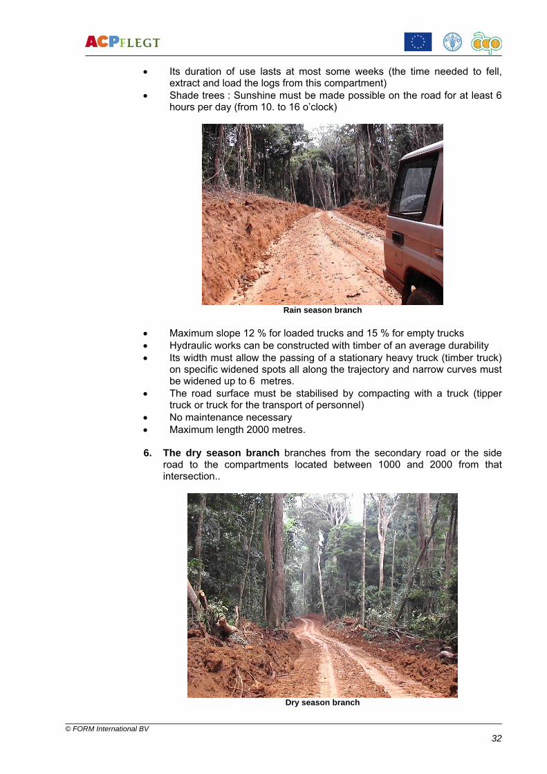
• No maintenance necessary. 5. The rain season branch branches from the secondary road or the side road to the compartments located between 1000 and 2000 from that intersection.
© FORM International BV 32
• Its duration of use lasts at most some weeks (the time needed to fell, extract and load the logs from this compartment)
• Shade trees : Sunshine must be made possible on the road for at least 6 hours per day (from 10. to 16 o’clock)
Rain season branch
• Maximum slope 12 % for loaded trucks and 15 % for empty trucks • Hydraulic works can be constructed with timber of an average durability • Its width must allow the passing of a stationary heavy truck (timber truck)
on specific widened spots all along the trajectory and narrow curves must be widened up to 6 metres.
• The road surface must be stabilised by compacting with a truck (tipper truck or truck for the transport of personnel)
• No maintenance necessary • Maximum length 2000 metres. 6. The dry season branch branches from the secondary road or the side
road to the compartments located between 1000 and 2000 from that intersection..
Dry season branch

© FORM International BV 33
• Its duration of use lasts at most some weeks (the time needed to fell,
extract and load the logs from this compartment) • Shade trees : No or little shade tree felling needed • Maximum slope 12 % for loaded trucks and 15 % for empty trucks • Hydraulic works can be constructed with timber of an average durability • Its width must allow the passing of a stationary heavy truck (timber truck)
on specific widened spots all along the trajectory and narrow curves must be widened up to 6 metres.
• No or little stabilisation of the surface needed • No maintenance necessary • Maximum length 2000 metres.
2.3 Impacts to reduce and RIL techniques to anticipate during the planning
Impacts to reduce • Destruction of the vegetation or bio-system by total removal of the
vegetation and total denudation of the soil over the entire length and width of the road
• Destruction of the original soil structure by mixing it up and compacting it • Interruption of the genetic exchange of tree-dwelling and aquatic species
by creating unbridgeable barriers for some species (roads, dykes, wide spaces between treetops, rows of uprooted trees along the roadsides)
• Erosion by lack of controlled drainage of rain water and by leaving as many as possible trees standing up-hill of the road.
RIL techniques to anticipate during the planning • Planning on the maps and tracing on the ground of the road network as
far as possible ahead of the road construction and the harvest (if possible, following the quenquennial plan)
• Planning of the roads as much as possible on the ridges of the hills and mountains
• Reduction of the length of the road network in relation to the planned log landings and skid trails
• Reduction of the width of the roads in relation to the foreseen intensity of the traffic, quarters of the compass and duration of use
• Planned culverts and fords across the deck for the drainage of water from the uphill gutters
• Planning of bridges and culverts with sufficient capacity in swampy areas • Planning of canopy bridges and corridors close to swamps and on hilltops
to facilitate the genetical exchange across the roads
2.4 Knowledge of the terrain
2.4.1 Introduction A profound knowledge of the conditions of the terrain is indispensable for the person in charge of the planning or, at least, for his subaltern that executes the tracing on the ground. It is possible to roughly judge the slopes, the ridges and the valleys by the contours, the width by the thickness of the blue lines and the locations where to construct bridges and/or dykes. However, only a real

© FORM International BV 34
exploration on the ground allows to judge more precisely the conditions for the construction of a road and for bridges and culverts and therefore one has to go there by foot. A visit to the construction sites will reveal the problems that can occur.
Road construction on the flank of a slope
2.4.2 Judgement of the conditions The conditions to distinguish and to judge that are indispensible for the planning are : • The slopes to conquer and the consecutively necessary groundwork. The
slopes can either be attacked frontally or by their flank. - On slightly or average slopey ground the road is preferably planned
along the crest of the ridge to facilitate the drainage and to reduce the ground works
- In terrain without continuous ridges the road will follow the flanks of the ridges to pass from one pass to the other
- In strongly slopey terrain the road is planned preferably along the flasks, but near the bottom of the valley.
• To consider the fact that drainage along the flank of a ridge is more complicated ( pipes to construct across the road deck) than with a frontal attack of the slope
• The drainage volumes of the water courses such as to decide on the location and size and type of the bridge to be constructed.
• The nature and exact limits of swamps ( to determine at the peak of the rainy season) such as to decide on a dyke to be eventually constructed with the given number of bridges and culverts.

© FORM International BV 35
2.4.3 Planning and tracing of the route Introduction and description
To be distinguished: • Main road (connections between the QU’s between the access road and
the main production area) • Secondary roads connection inside the QU between the main road and
the compartments or pockets) • Side roads (connection between the secondary road and the grouped
compartments or pockets (or, in case of isolated compartments or pockets passing by a branch to this compartment
• Branches (rainy or dry season quality, connection between the log yard and the closest side road)
• Log yards (also called log landings, sidings or markets) • Main skid trails These main types of forest roads already have to be distinguished during the planning, because they differ strongly in costs of road construction, bridges and culverts and maintenance, but above all in the intensity of environmental impact. It often proves to be practical to also have the tracing and tracking of the main skid trails executed by the road tracer, as he is already present on the ground and has taken knowledge of the conditions and the obstacles. For this reason we treat the tracing of the main skid trails in the module of road planning. Another reason is the fact that in dry season, if the conditions of the terrain allow so and after a light scraping by a grader, the main skid trail may serve as a branch for the logging trucks. In that case a log yard will be opened at the end of that trail. Planning and tracing
Criteria : • Distance (the shortest possible). The maximum skidding distance
stipulates the distance and tracing of the roads. • Bridges (to avoid as much as possible the crossing of water courses, to
restrict as much as possible the number and size of the bridges (cost, time, environmental impact)
• Ridges (to follow where possible the ridges such as to reduce the earth movement, to reduce the number of bridges to build, to facilitate the drainage of rain water and to allow as much as possible the skidding in uphill direction (RIL !) and to restrict the steepness of the slopes for the logging trucks)
• Ground and soil conditions (rocks, swamps, sandy/loamy/laterite soil) • Quarter of the compass of the road (to allow as much as possible
sunshine on the road : E – W is preferable to N – S) These five conditions have to be constantly considered and balanced against each other during the planning and tracing of the forest roads.
2.4.4 Intensity of the road net The intensity of the road net corresponds with the total of kilometres of roads constructed on a given surface of forest. The surface we take as reference is 1000 hectares.

© FORM International BV 36
As comparison we take the circumstances in two different countries : • Table 1:
In Ivory Coast, where the volumes are calculated in cubic metres (m3) of various timber species and in road net intensity with simple skidding, i.e. with a single engine (track- or tyre type) from the stump to the log yard on the road side. The density of exploitable trees in number and in volume is here far inferior to that of Gabon. On the other hand, the conditions of the terrain are here far easier.
Topography Harvested volume in m3/ha
Intensity of the road net in km/1000 ha
Easy terrain 4 6
7 - 10
6,8 8,5
10,8 Average terrain 6,1 10
• Table 2 :
In Gabon, where the volumes are calculated in m3 of a mix of Okoumé and various species and the road net intensity both withoù l’on a calculé
Simple skidding As with skidding in 2 phases primary and secondary skidding :
- From the stump to the main skid trail with a track type tractor - Along the main skid trail to the log yard with a tyre type tractor
(« skidder »)
Topography Simple skidding
Primary and secondary skidding
Volume harvested in m3/ha
Intensity of the road and main skid trail net in km/1000 ha
Easy terrain 10,5 4,8 + 4,5 11 10 13 6 + 5,6 Average terrain 10,5 4,1 + 8,2 8 7 – 8 Difficult terrain 10 10,8
The road nets are drafted consequently. From these data results that the skidding in 2 phases allows to lengthen the skidding distance and consequently shorten the road net considerably.
2.4.5 Road net in relation to the skidding distance For a flat terrain the criteria are simple. One calculates on the basis of compartments of 100 hectares (1,000 x 1,000 m) with a maximum skidding distance (primary + secondary skidding) of 1,000 – 1,200 metres. From this ensues that roads are to be opened each 2,000 metres. In hilly terrain, where the road must follow the ridges, this calculation does not apply, because: the skidding distance becomes dependent of the nature of the terrain. The main skid trails also follow the ridges. To avoid baseless discussions, because no rules can be fixed as there are so many different circumstances in the region, for really hilly terrain we stick to empirical rules as for maximum distance of primary skidding of 200 – 300 metres and for skidding by skidder 1,000 metres on main skid trails.

© FORM International BV 37
Methodology
When the QU is being subdivided into AAC the access (and connecting) road and the main roads are being planned on the original QU map (map IV) at a scale of 1 / 125,000, but enlarged up to 1 / 50,000, whilst seriously taking into account the criteria described under 5.4.2. The lines shall be a straight as possible, considering the obstacles indicated on the map. Once the main road net of the QU has provisorily been marked, these sketches are transported to the QU map scale 1 / 50,000, format A3, for the planning of the secondary roads, the side roads and, eventually, the log yards, whilst again seriously taking into account the criteria described under 5.4.2. The road net thus having been planned, the tracking team goes to the field with the map VIII of the AAC at hand. The team consists of 1 tracker (or the foreman himself) with 2 cutlass men holding a GPS or a topofil and a compass, marking tapes, marking paint and their cutlasses. First they open a more or less straight line, following exactly the trace indicated on the map. The obstacles are meticulously marked and described, but not by-passed. Arrived at a certain point, most logically by mid-day, the team does an about-turn and whilst searching for the shortest and most efficient by-passes of the obstacles, it enlarges the line to 1 metre width and fixes coloured marking tape on twigs and shrubs along the track. Too steep slopes are to be avoided. The following slopes are to be considered as maximal : For loaded timber trucks (leaving the forest) 12 %, for empty timber trucks (entering the forest) 16 %. Steeper slopes can be considered, but only on short stretches and with lesser loads. Instead of coloured marking tape paint can also be used, but alsoin bright colours. It can turn out to be necessary to pass a third time for the final determination of the direction and the width to ensure that the deviations prove efficient over a longer distance. At the same time the team marks with tape or paint on twigs or shrubs the width of the track to be opened by the bulldozer. All vegetation has to be removed and trees are to be uprooted. This width depends on the qualification of the road (main, secondary or side road)and varies amongst them in metres. Back at the starting point, the foreman traces on the map the exact trace covered and opened. Having saved the GPS waypoints he delivers these to the forest manager’s office for downloading into the GIS.
2.4.6 Knowledge of the road construction techniques Introduction The techniques of the construction of forest roads to be considered during the planning relate to the following operations : • Clearing of the undergrowth • Clearing of the larger trees (uprooting, bucking and removal) • Felling and removal of the shade trees • Levelling, profiling

© FORM International BV 38
• Cutting of the slopes • Crossing of water courses • Construction of drains (gutters, drain pipes, fords) • Construction of bridges All these operations have their specific techniques in the interest of the quality and efficiency of the road and in the interest of the environment and are treated under paragraph 5.7.2 here below. Description of the engines and vehicles for the road construction The most sophisticated road construction engines have been introduced into the world of the logging industry without having brought the improvements to the techniques and the results that would be consistent. For this reason we confine ourselves to the engines and vehicles that are most often brought into action in small and average logging operations. The engines treated in this module are only : • A bulldozer • A grader • A frontend loader (payloader) • A tipper truck Scrapers, traxcavators, compactors, etcetera, will not be treated. They are certainly very useful machines, increasing the efficiency and quality of the road construction, but weigh too heavily on the budget of small and average scale logging enterprises. CATERPILLAR being the most known and widespread brand and most represented in this project, has been taken as example, although quite some other brands produce engines with equivalent capacities. The used engines are described in the diagram here below.
Type Model Capacity Weight Utilisation Observations
Bulldozer D7R 240 HP 25 t Forest clearing. Levelling. Bridges, skidding
Blade with push bar and tilt ; winch with high arch ; high engine with raised shaft ; most recent model
Bulldozer D6R 165 HP 18 t Forest clearing. Levelling. Bridges, skidding
Blade with push bar and tilt ; winch with high arch ; high engine with raised shaft ; most recent model
Grader 140H 185 HP 14,6 t Gradering ;profiling, drainage
Powerful machine for difficult terrain and hard soil
Grader 120H 140 HP 12,6 t Gradering ;profiling, drainage
Less powerful for less difficult terrain
Payloader 966G 14 T 22 t Loading of earth, gravel and logs
To be delivered with both shovel and fork
Payloader 924G 5,5 T 10 t Loading of earth and gravel Only with shovel
Tipper truck ? ? 5 – 15 T Transport earth and
gravel
Can also be used for transport of workforce and materials

© FORM International BV 39
For reasons of multifunctionality the bulldozer should always be equipped with winch and high arch. These accessories have proven to be very efficient in road construction for the skidding and positioning of the girders of bridges and culverts. Tracing of the main skid trails For the tracing of the main skid trails on flat land it will be sufficient to follow the enumeration lines and to mark the junctions of secondary trails with paint or colored tape. On slopey terrain the tracer follows the track indicated on the map with help of his GPS or his compass and a clinometer. The following inclinations are to be considered as maximum : Inclination for loaded trucks: 10 %, Inclination for loaded trucks: 15 %. Steeper slopes are to be surrounded or to be attacked on their flanks. For the opening of main skid trails in pockets or secondary trails in compartments it is generally practical to make one of the cutlass men advance in the requested direction, either with the compass or GPS or simply by making him search for the tree or an aiming point on the map and once he has arrived there to make him return on his tracks keeping a vocal or whistling contact with the clerk and with the other cutlass man. The cutlass men approach one another in a straight line opening the track. Whilst advancing on the track paint marks are applied on bordering trees.
Opening of a main skid trail on a slope
2.5 Drainage, bridges, culverts
2.5.1 Drainage The biggest impacts on the road are often caused by problems with the drainage of rainwater. These impacts are mostly erosion of the surface and the borders, sedimentation of the valleys and in the waterways and decline of the quality of the water. Furthermore insufficient drainage causes shifting of the top layer (gravel) of the road deck and furrows across the road and softening of the deck, whereby heavy timber trucks cannot pass anymore.. Therefore the perfect drainage of water is of utmost importance with road construction and maintenance.

© FORM International BV 40
Construction of a forest bridge
RIL measures • To make sure that the drains and gutters do not lead directly into
waterways, but in the undergrowth further uphill, to prevent silting of the water
• To construct sufficient drains, pipes, fords and culverts to reduce the force and quantity of the water masses flowing down and thus reduce the erosion.
• To make sure that the drains are not any wider and longer than necessary • To place mud traps upstream of the culverts, pipes and fords to slow
down the mud stream and to avoid as much as possible the silting of the streams.
Gutters The gutters must ensure the evacuation of rainwater by drains from the road deck along the road side towards the undergrowth. They are prepared by a bulldozer and perfected by a grader.
• Many small drains are more efficient that a few large ones to reduce as
much as possible the quantities of water and reduce erosion and silting. The number of drains on a slope is stipulated by the degree of steepness.
Drains Drains evacuate rain water fom the gutters into the undergrowth, thereby reducing the quantity of water so large that it causes heavy erosion and silting of the valleys.

© FORM International BV 41
• The drain must lead into the undergrowth and not stop at the naked soil to ensure a good spreading and absorption of the water and does not become a stream itself.
• The drain should not lead too far into the undergrowth either to avoid that it creates a stream itself.
• The end of the drain must be free so that there will be no standing water at the end
• The profile of the drain must be in V shape. The CAT operator therefore has to use the tilt of his blade. This reduces the earth movement, is faster to open and reduces the damage to the forest.
Drain in V shape
• Minimal distance between the drains in relation to the angle of the slope:
Angle of the slope Minimal distance between drains
0 – 5 % 60 metres 6 – 10 % 40 metres 11 – 20 % 30 metres > 20 % 15 metres
2.5.2 Pipes, culverts and enforced fords The pipes, culverts and enforced fords have to evacuate the water from the gutters across the road deck on the uphill side of the road and from places where drains into the undergrowth are impossible (rocks). 1. Culverts and pipes are the cheapest and easiest to construct by hollow
tree trunks. However these pipes get clogged too easily and should therefore not be used.

© FORM International BV 42
Pipe made with hollow trunk- not preferred
2. The best known culverts are those made by three logs, whereby two logs
of the same diameter are placed parallel on the bottom with a space in between on top of which a third log of a larger diameter is placed and the whole covered with soil. The width between the down logs determine the flow capacity of the culvert, but it is quite difficult to keep the culvert open. These three-logs culverts shall therefore be used only on roads with a very limited use (branch roads only).
3. Culverts constructed with a slab or slabs of wood with a thickness of 20 – 30 cm (in relation with the length of the span) covering the entire width of the road deck and resting with their ends on crossbeams made of squared logs are long lasting. These do not have to be covered with soil.
Culvert made of slabs on notched logs - SBL
4. Prefabricated concrete pipes or made of wooden boxes demand a far
more precise opening of their bed and a thick layer of soil on top, but are very durable and stable.
5. The entrance of the water into culverts and pipes must be guided by a structure in the shape of a funnel made of boards, poles or plaited twigs.
6. The entry of the water into culverts and pipes must be guided by a funnel-shaped structure made ut of boards, poles or woven twigs. This funnel restricts erosion on both sides of the culvert and silting at the entrance.

© FORM International BV 43
Protection against erosion and silting of a culvert
7. It must always be possible to unclog a culvert over its entire length 8. The trees of the desired species, quality and length for the construction of
the culvert have to be sought in the vicinity of the construction site (to check inventory map!). Logs brought from far away is time consuming and costs money.
9. An alternative for culverts in a relatively flat terrain is the enforced ford, created by a depression in the road deck and enforced with rocks and stones, over which the water can flow and across which the vehicles can pass with a reduced speed.
10. The site, size and type of bridge or culvert are to be selected meticulously to ensure a free and correct flow of the water
Culvert made of slabs on notched logs - SBL
11. Do not clear any more than necessary the undergrowth from the banks on the surroundings of the site of the bridge to avoid erosion and silting
12. The water course is to be cleared of all branches and other debris after completing the bridge or culvert to avoid clogging.

© FORM International BV 44
2.5.3 Bridges
Canadian Bridge – CEB Thanry
The site and type of bridge are chosen on the below-mentioned criteria and the planning of that section of the road is subject to these. a) The type of bridge is determined by: • The necessary length of the bridge to span to the riverbed at its maximum
water level (full rain season) • The weight to support (for logging trucks with a maximum weight of
approx. 50 tons) • The traffic frequency • The composition of the soil and the banks (the bridge deck must be at a
minimum of 1 metre above the maximum level of the water and this on firm soil)
• The requested lifespan, that must extend the duration of the harvest of the entire FMU.
b) The site must satisfy the following conditions: • The crossing (distance between the banks) must be as short as possible
(max. 15 metres) at right angles with the water course, to avoid as much as possible the construction of piers
• The structure of the banks must be as strong as possible (rocks or at least sand or hard loam)
• The terrain must permit an approach at right angles with the water course over at least 50 metres, so exceeding the length of the logging truck combination
• The crossbeams must be placed as high up as possible on the banks on firm soil to ensure a stable base and reduce the risk of caving in.

© FORM International BV 45
Construction of banks for a Canadian bridge – CEB Thanry
c) To satisfy the above mentioned conditions there is a choice between the
following types of bridges, all made out of hardwood: Log bridge on land abutments (crossbeams)
Log bridge on land abutments (crossbeams)
The easiest and simplest bridge is used on watercourses with stable banks without risk of caving in, even at the highest water level. • The abutments are each made of three piled-up logs of diameters
between 60 and 100 cm, placed along the banks on a stable soil. • Notches are cut with a chainsaw in the upper log for a solid positioning of
the sleepers. The deck is made of cross-boards and boards for the wheel tracks. Bridge with crosswise stacked abutment or ”Canadian bridge” Banks of an insufficiently stable soil or on a feeble slope can require reinforced abutments by crosswise stacking logs both perpendicularly and parallel to the stream • These logs are fixed on their place by notches in the underlying logs. The
layers of logs perpendicular on the watercourse create an anchorage of the abutment in the banking up.

© FORM International BV 46
Bridge with crosswise stacked abutment or ”Canadian bridge” – CEB Thanry
Bridge with concrete or brick abutment Bridges with a planned long lifespan, on a very unstable soil and/or on very strong and turbulent currents can be built with concrete or brick abutments. • These abutments can, of course only be built only at the lowest water
level and on a dry soil. • The wall, serving often at the same time as barrier for the banked-up
earth, must be thicl enough to resist to the pressure of the earth.
Bridge on piers (piles)
When the riverbed is too wide for a single span, intermediate piles are to be constructed on which the ends of the sleepers are resting.
Bridge with two spans of 15 m. each . The sleepers are made of
squared Kussia logs. - Cote d'Ivoire. Photo C. Lepitre The piles (piers) are constructed either with concrete or bricks or with piles of crosswise layers of notched logs.

© FORM International BV 47
• In order to restrict the pressure of the water against the base of the pile, it is advised to construct this in a lozenge-shape with the sharp points in the set of the current
• The piles of crosswise layers of notched logs can be left with an open interior open, to be filled up with rocks or large stones
Bridge with an earthen deck
Simple bridges with a relatively short live span can be covered with a thick cover of laterite • For this the sleepers have to be placed tightly one against the other over
the entire width of the bridge and the eventual gaps have to be filled with small diameter billets or sticks, also in hardwood.
• The bulldozer applies dry laterite layer by layer with its blade after having created a ramp with this same laterite, preventing it to push against the face of the logs. Applying thin layers allows an appropriate compacting by the tracks
• The complete layer of the laterite must be of approx. 40 cm thickness • Logically the weight of this layer of 35 – 40 m3 of laterite reduces
considerably the carrying capacity of the bridge • The laterite retains the humidity and thereby quickens the rotting process
of the sleepers • The distinction between mainland and bridge deck is definitely leas clear
and represents a serious danger for the approaching traffic, especially at night. Clear road signs and speed bumps are necessary here.
Bridge with wooden deck (Beams)
• A deck of wooden beams does not need more than 4 or 5 sleepers. These
sleepers must be flattened on top or squared for a more stable positioning of the beams.
• It is advised to place the beams that serve as strips for the logging truck’s tires right on top of sleepers, so sleepers have to be positioned beforehand on the correct distances
• The wooden deck consists in general of a base of beams of 7 – 10 cm thickness nailed or screwed perpendicularly with a mutual distance of 10 – 20 cm over the entire width of the sleepers
• On this platform a deck of beams of approx. 5 cm thickness and a width of 10 – 15 cm is fixed at a mutual distance of 5 cm. It is best to position these beanms at an angle of 45° on the base below to obtain a better absorption of vibrations caused by passing vehicles
• Boards of approx. 3 – 4 cm thickness as strips for the logging truck’s tires are fixed lengthwise at the width and mutual distances of the sets of tires
• The best way to fix beams and boards on the underlying decks is to use large woodscrews in pre-drilled holes. These loosen less easily than nails and can be re-tightened.
• The trees of the desired species, quality and length for the construction of the culvert have to be sought in the vicinity of the construction site (to check inventory map!). Logs brought from far away is time-consuming and costs money.

© FORM International BV 48
Canadian bridge with wooden deck – CEB Thanry
• If time permits, sleepers are to be squared by chainsaw to create a
smoother base for the beams • Slabs of 20 – 30 cm thickness can be cut by chainsaw for decks on large
culverts or narrow bridges and as crossties on larger bridges
Scale model of a wooden deck
• Sleepers with a diameter of 60 – 85 cm and as straight as possible
support the wooden deck. 4 or 5 will be sufficient if 2 or 4 are placed right under the strips for the truck’s tires.
• The regional RIL Code by the FAO gives the following relation between span of the bridge and diameter of the sleepers with different species:
Span between abutments
10 m 12 m 14 m 16 m 17 m
Congotali 58 cm 66 cm 74 cm 81 cm 85 cmBilinga 63 cm 71 cm 79 cm 86 cm 90 cm
For a span longer than 17 metres an increase of 4 cm per metre supplementary span must be counted.
For bridges with a shorter lifespan than 3 years hardwood sleepers do not have to be de-sapped. For a longer lifespan it is strongly advised to at least de-sap the surface that carries the deck.

© FORM International BV 49
2.5.4 RIL The specific RIL measures to be considered during the planning of the forest roads are the following : In general: • To keep the road net as short and straight as possible by meticulous
planning and tracing on the map and on the ground. • To respect the buffer zones With the clearing : • To restrict the track for the clearing of the road deck with its planned
banks and gutters on the prescribed maximum width by two lines marked by coloured tape or paint advancing perfectly parallel.
• To mark with paint or tape the trees to be salvaged (protected species, future crop trees, monumental trees)
• To restrict to the absolute minimum the clearing width during the tracing, i.e. not to exceed the clearing width of the road deck with its planned banks and gutters
• To facilitate the genetic exchange and migration of species (canopy bridges, corridors for crossing by animals).
With the felling of shadow trees: • Only shadow trees that hinder the drying up of the road deck during
sunshine are to be selected (marked by tape or paint) for felling by chainsaw
• The quarters of the compass are indicative for the necessary width of the felling of the shadow trees. A road leading East – West (quarters NE - SW to NW – SE through East – West ) catch far more sunshine and need far less shadow tree felling than roads leading North – South (quarters NE to SW to NW – SE through North - South
• To conserve trees and shrubs that can serve as canopy bridges (at the summits of ridges) and as crossing corridors (on well compacted and gravelled areas) for animals.
With the levelling: • To restrict by tape or pickets on the ground before clearing the levelling to
the width prescribed in the plan • To mark and stake out the areas where earth movements have to take
place • To restrict the earth movements to a strict minimum • To avoid to push the earth into streams along the track. With the cutting of slopes: • See 5.3.2 Judgement of the conditions. • Before starting the cutting of a slope the forest manager or the foreman
has to judge whether the slope has to be attacked frontally or by the flank (impact by digging off and filling up or impact by opening over a larger distance) and he will instruct the engine operator accordingly.
With the construction of bridges and culverts: • To choose the site, the size and the type of bridge or culvert in order to
ensure a free drainage of the water • Not to clear more than necessary the banks of the water course at the
construction site • Clear the water course of branches and other debris after completion of
the bridge or culvert to avoid a blockage

© FORM International BV 50
With the profiling: • To apply a sufficiently distinct profile of the road deck to ensure the
drainage of the water directly from the road deck into the gutters and not along the axis of the deck
With the traffic safety: • To plan the right places to park or pass • To plan the curbs (width, visibility, signboards) • To plan the approach of bridges (curbs, speed ramps, signboards)

© FORM International BV 51
3. CONTROLLED FELLING
3.1 Introduction and interpretation of the impact of tree felling and the RIL techniques
3.1.1 Introduction The impacts of the felling of a tree on the remaining stands can be the following: • Destruction or damaging of trees to be protected (FCT’s, seed trees,
protected species) • Destruction or damage of the habitat of organisms in the trunk and crown of
that tree • Destruction or damage of the vegetation by the trunk and crown • Destruction or damage to the remaining stands by vines dragging along
branches of neighbouring trees • Trees to be protected (FCT’s, seed trees, protected species) have to be
marked by the selection team for the chainsaw operator can try to spare them when felling.
Monumental trees of exceptional dimensions (over 2 metres diameter above the buttresses) shall also be spared as the harvesting of such trees demands often so much efforts with felling, crosscutting and extraction that the loss of time and
Monumental trees to be spared. . . wear-and tear of the equipment is not justified by the volume harvested and the possible yield of the tree. The value of such trees for the natural regeneration, of their species because of their genetic properties and as provider of huge amounts of seeds should not be underestimated.

© FORM International BV 52
Apart from the damages to the remaining stand the damages to the timber itself of the felled tree, like pull-outs, splits, cracks, ring-shakes can also be restricted by the application controlled felling techniques. Maintenance of the chainsaw and chain-sharpening are imperative subjects for the proper functioning of the machine and the safety of the operator and his mate.
3.1.2 Safety prescriptions General rules The use of a chainsaw can be very dangerous. The chain with its sharp teeth at full throttle can reach a speed of 70 kmh! Safety for the operator • The operator must be in a good physical condition, not tired and not under
influence of alcohol or drugs • Long-time use of the chainsaw can cause the “white fingers syndrome” or
“Raynaud phenomenon”, a disorder of the Carpian tunnel, which caused a loss of feeling in fingers or a burning sensation. The use of a saw with an anti-vibration system (AV), AV – gloves and a well sharpened chain can prevent this.
Clothing • The operator must be dressed correctly, i.e. no loose or torn sleeves or
trouser legs, but leaving a complete freedom of movement. • He must wear protective leggings • Anti-slip gloves • Strong rubber boots or safety boots with anti-slip soles • Safety helmet: Wear an approved helmet with ear protectors and visor • Wear a safety vest in bright reflecting colours to be more visible in the
forest.
Security clothing The modern chainsaw is equipped with the following safety provisions: • Anti-kick-back protection with chain brake • Throttle lock, preventing any accidental acceleration

© FORM International BV 53
• Safety chain • Anti-vibration provisions • Chain catcher (in case of breaking or jumping off of the chain) • Protection for the right hand (in case of breaking or jumping off of the
chain) • Never execute any modification on the chainsaw.
3.1.3 ”Kick-back” A kick-back occurs when the upper part of the tip of the blade touches a hard object or is trapped.
This happens often with the cutting off of branches under tension.
Modern chainsaws have a chain brake serving at the same time as hand protection that is engaged by the left wrist when the machine jumps up. Also some types of chain have kick-back reducing properties.
3.2 Techniques of controlled felling
The whole of the principles and actions of controlled felling can be demonstrated on a small tree of approx. 20 cm diameter as shown on the picture below.

© FORM International BV 54
Demonstration of controled felling on a reduced scale
3.2.1 Determination of the falling direction and opening of escape routes • Before felling a tree the operator must consider all conditions that can
influence the falling direction • On a steep slope escape routes have to run parallel to the slope • Put down the tools and other objects at a sufficient distance, but not on
the escape routes. Safety measures before and during the felling Verification of the elements that can create dangers: • Dead branches in the canopy • Vines attached to the canopy • The canopy is entwined with other canopies • The tree is hanging • Another tree is leaning against the tree to be felled • Strong winds Safety conditions: • Only trained and experienced operators are allowed to operate the
chainsaw • Only workers of the felling team are allowed near the tree to be felled • Always check the condition of the tree: rotten heart, hanging or under
tension that can cause the trunk to burst or split, risking to cause serious accidents
• Check the tree to be felled and surrounding trees for dead or broken off branches that can drop by the effect of the vibrations
• The operator has to ensure that nobody, apart from his mate, is in the danger zone
• When felling on a slope the operator must make sure that he is first at the down-hill side to apply the directional cut

© FORM International BV 55
• Before starting felling close to a road a helper must position himself on that road to stop any traffic and clear road signs must be placed just outside the danger zone
• Before applying the felling (final) cut, the engine has to be stopped and with a whistle or loud voice any persons possibly within the danger zone must be warned for the imminent falling of the tree
• At the moment of falling always stay at the side of the trunk and get away laterally towards the escape route
• Stop the saw when the tree starts falling and warn everybody by voice or whistle
• Beware of falling branches when moving away from the tree • After the falling wait some minutes before returning to the tree to check for
falling branches or dead wood • When the tree has fallen, advise the surroundings so that they can
approach (foreman, clerk, marker)
3.3 Bucking and crosscutting techniques
3.3.1 Description and methods Separating the crown from the felled tree can best be done some time (+/- 1 week) after felling to allow the tension in the wood to subside. This is especially important for species that have a strong tendency to split. It also increases the safety as during this time the eventual loose pieces of wood in the canopy can fall down safely. Thirdly when a bees or wasp nest is disturbed in the canopy these animals generally have moved away a few days after the felling and will not attack the workers anymore. Bucking of the down part is not treated here, but under Log yard operations, as on the log yard the quality of the tree can better be judged. Therefore the removal of the buttresses on the standing tree during felling is important. Correct removal of buttresses • Reduced the damage to the soil • Reduces the resistance during skidding • Allows for a better yield of the log Recommended is to have approach and the length of the trunk cleared by the crosscut operator or his helper with his cutlass. This will reduce the loss of time for the bulldozer and at the same time prevents damage by the dozer by clearing the log for the crosscutter, which is not considered RIL.

© FORM International BV 56
Bucking of the crown
3.3.2 Choice of places to crosscut The best place to cut off the crown is in the fork of the first branch. As the structure of the wood is very knotty and dense at those places, this restricts considerably the starting of cracks during the bucking. At the same time the crosscutter cannot waste useful wood by bucking too far down the trunk. Appropriate bucking of the crown is proven by a double heart on the face and should be required by the forest manager. As the double heart is considered a defect by the processor of the log, i twill be eliminated at the log yard anyhow.
Correct bucking of the crown, showing a double heart
Crosscutting of the trunk is only justified when the trunk is too long or too heavy to be extracted entirely. In that case the place for crosscutting must be marked by the forest manager, the foreman or the log yard clerk, who are experienced in judging qualities and requirements concerning lengths. In all other cases crosscutting must take place at the log yard, where the quality of the trunk can much better be judged.

© FORM International BV 57
3.3.3 Crosscutting techniques • The trunk must be placed as flat as possible with its mayor part resting on
the ground • Support the trunk at both sides of the planned cut with chunks of wood • After measuring the entire tree length the log yard clerk chooses the log
lengths in relation to defects to be eliminated, the quality of the individual portions and the lengths to be considered for the yield of the processing
• The crosscutter cleans the cutting area properly with his cutlass and digs a free space, if necessary, to avoid cutting into the ground
• After starting the chainsaw he places it well perpendicularly on the length of the trunk and accelerates to start cutting
• He should not exercise too much pressure on the chainsaw, as a well sharpened chain “eats” its way through the wood easily and should not be “suffocated”
• As soon as the blade has entered approx. 20 cm (more that 2x the width of the blade) into the trunk, a plastic, aluminium or wooden coin (wedge) is hammered into the cut to prevent it from closing and jam the blade (see picture)
Wedge in the cut and supporting blocks under the trunk • Trunks with a diameter superior to the length of the blade shall be cut first
on one side way down, next on the opposite side. • Another practice is for the operator to stand on the trunk and start cutting
on one side with the blade pointing down. After that he gets down and cuts the other half standing on the ground. With this practice it is very important that the operator has a firm footing!
• Trunks with a diameter superior to the standard length of the blade (90 cm = 36 “) will have to be crosscut with a blade of 106 cm = 42 “ or even 120 cm = 47 “with, of course, corresponding chains.
Crosscutting of trunks under tension: • If the area of the crosscut is situated on a part of the trunk that is off the
ground, both sides of the planned cut must be supported steadily by chunks of wood (off-cuts) to prevent cracking or splitting of both logs when the cut is almost completed.

© FORM International BV 58
• If it is not possible to support both sides of the planned cut, the following technique has to be applied (see A below): 1. Always apply a first cut on the side of the compressive tension (1)
down to 1/3 of the diameter of the trunk. 2. Always hammer a coin into the cut, as soon as the blade has
sufficiently entered 3. Next start sawing on the side of the contractive tension (2) until the
two cuts join and the remaining wood breaks • If only one side of the planned cut on the trunk is suspended and cannot
be supported, the following technique has to be applied (see (B), now starting to cut from downside upwards: 1. Always apply a first cut on the side of the compressive tension (1)
down to 1/3 of the diameter of the trunk. 2. Always hammer a coin into the cut, as soon as the blade has
sufficiently entered 3. Next start sawing on the side of the contractive tension (2) until the
two cuts join and the remaining wood breaks
3.3.4 Safety measures • If the part of the trunk to crosscut is under lateral tension (standing or
suspended tree) open first an escape route perpendicularly on the falling direction
• If there is a risk of one of the logs starts rolling, block the log with a chunk of wood and start cutting on the downhill side of the trunk and make the final cut on the uphill side
• Always use a coin (wedge) to prevent the blade to jam.

© FORM International BV 59
3.4 Sharpening of the saw chain
Instruction in chain sharpening
3.4.1 General conditions A well sharpened chain cuts the wood without efforts, even under only slight pressure. Never saw with a blunt or damaged chain. This renders the job unnecessarily tiresome and too much strain is put on the equipment. A wrongly sharpened chain, especially with the depth restrictor filed off too far increases the risk of a kick-back with serious injuries as possible results. Every evening the operator must: • Clean the chain with gasoil of all sawdust and resin • Check if the chain links are not cracked and the rivets not damaged • The mechanic must every evening: • Replace the damaged or used elements of the chain and rectify the new
elements according to the shape and degree of wear of the remaining elements.
3.4.2 Hand sharpening tools • Round files: the diameter of the round files must fit the size of the chain: a
.404 chain needs a 3/16” file and a 3/8” chain needs a 5/32”file. • A file holder with alignment signs for the correct angle of the cutting edge
of the teeth • A sharpening gauge to check the cutting edge, the front angle, the height
of the depth restrictor, the length of the teeth and the depth of the groove of the blade. A small protuberance at the end of the gauge serves to clean the groove of the blade and the holes for the chain oil
• A small flat file to reduce the depth restrictor

© FORM International BV 60
3.4.3 Maintenance of the chainsaw
Maintenance instruction
The chainsaws with their blades and chains must be brought back to the workshop at the end of each day for check, cleaning with compressed air and eventual repairs in the evening, so that the chainsaws are in good order the next morning.

© FORM International BV
61
4. EXTRACTION PLANNING AND TECHNIQUES
4.1Introduction and interpretation of the impact of the extraction
Introduction, description The negative impacts on the forest environment by the extraction (both on log yards and on skid trails) are caused by : • Destruction of the environment on the log yard and on the skid trails • Destruction of the original soil structure • Compacting of the soil in the trails of the engines • Soil erosion • Negative impacts on the water courses
- Damming - Changes of watercourses - Silting up - Damage to the banks with their typical environments
• Vanishing of wildlife because of the presence of noisy equipment and people.
• A well-trained skidding foreman is indispensible to apply the RIL measures.
4.2 Opening of skid trails
Planned and cleared main trail
Three different types of skid trails are distinguished : 1. Main skid trail, leading from the log yard in a line as straight as possible
to the end of the compartment, to be used by the skidder 2. Side skid trail, a branch of the main trail, necessary to restrict the
secondary skidding distance by the bull to a maximum of 500 metres on flat land by the skidder to 100 metres or even less on strong slopes, to be used by the bulldozer
3. Clearing trail , the trail leading from the stump to the first junction with the secondary skid trail or main skid trail, to be used by the bulldozer or CAT 527.

© FORM International BV
62
Main trail on a flank • To avoid curves that are too tight, curves ≥ 135° are preferred • To avoid bifurcations with angles < 135° • To spare (by skirting) trees that are marked as protected, seed trees and
future crop trees, whilst respecting the curves to be ≥ 135° • A buffer zone must be marked along water courses with widths according
to the below table :
Width between banks Width of buffer zone
< 5 metres 2 x 5 metres 6 – 10 metres 2 x 10 metres 11 – 20 metres 2 x 20 metres 21 – 30 metres 2 x 30 metres > 30 metres 2 x 30 metres Streams, marshland 2 x 5 metres Swamps, lakes 10 metres from edge of the water
• To respect buffer zones along water courses, swamps and protected
areas by a unique crossing per compartment • To carefully cut steep banks to avoid damming.
4.3 Engines used for extraction
4.3.2 Introduction, description The typical engines used for extraction are track-type tractors, generally known as « bulldozers » equipped with a dozer blade and a winch and articulated wheel tractors, equipped with a small blade, a high arch and a winch, called « wheel skidders ». A third type is the track-type skidder with a small blade, a high arch and a winch, very populr in the hilly forests of central Africa. The most widespread brand is CATERPILLAR, of which the below mentioned types are commonly encountered in the logging operations.

© FORM International BV
63
Model Net power Weight Track type KW HP KG
Chassis Blade Observations
D6R XL 138 185 18.700 Rigid Lift & tilt Winch and arch in option D7R XR 179 240 25.300 Rigid Lift & tilt Winch and arch in option 527 112 150 17.000 Rigid Lift Winch and arch in option Wheel type 525 134 182 15.400 Articulated Lift Winch and arch standard 535 149 202 15.800 Articulated Lift Winch and arch standard 545 168 225 18.200 Articulated Lift Winch and arch standard
The drum of the winches can contain between 25 and 45 metres of steel wire, depending on the thickness of the wire The high arches on the winch (optional with the track-type tractors) are indispensible for skidding as they allow to lift the end of the log off the ground and thus strongly reduce the friction and the creation of furrows that cause a resistance to the traction, destroy the structure of the soil and favourise erosion.
4.3.3 Track-type tractors CAT D6R and D7R The track-type tractors CAT D6R and D7R are almost always equipped with a heavy and tilting dozer blade fixed at the front. Advantages : • A tractor thus equipped is polyvalent, i.e. it can be used for road
construction, clearing and skidding • The tracks, in combination with its own great weight, give it a great
traction, resulting in little spinning, allowing to haul very heavy logs that sometimes even exceed their own weight
• The track-type tractor can attack far steeper slopes (up to 40%) than a wheel skidder
• The weight of the vehicle is spread over a greater surface, which results in less compacting
Disavantages: • Very heavy machine • Fuel consumption higher that a wheel skidder • Slower than wheel skidder • Tracks causing more damage to the vegetation on the ground than a
wheel skidder • More expensive than wheel skidders
4.3.4 Wheel skidders The wheels kidders CATERPILLAR 525, 535 and 545 are built with an articulated chassis and large tyres (1.45 m or more). Advantages: • Great manoeuvrability • High speed, with or without load (27 kmh) • Very high arch on the winch, allowing to lift up large logs • Tyres cause less damage to the soil, if they do not spin

© FORM International BV
64
• Fuel consumption lower than that of the track-type tractor • Lower purchase price than the track-type tractor Disavantages: • Less efficient in very accidented terrain (max slope with load 25%) • Risk of spinning with a load, especially on muddy soil • Lower load capacity in relation to its power compared with track-type
tractor • Blade only to be used to clear scrub and to range logs, too weak for earth
movements Combined skidding with both types is much more efficient that skidding with one type only. .
4.3.4 Track-type skidder The track-type skidder Caterpillar 527 has been introduced some 15 years ago and is specially developed for skidding. It is equipped with a winch with a high arch on top and has an hydraulically commandeered angling (horizontally) and tilting blade, that is however not strong enough for serious earth movement, but serves to range logs and scrape off vegetation. Avantages : • The hydraulically commandeered angling (horizontally) and tilting blade
allows light earth moving and gradering, very useful for opening main skid trails, road and drainage repairs (instead of a grader)
• Can be used for both clearing, primary and secondary skidding • High arch, mounted on top of the winch, allowing to lift the end of large
logs off the ground
CAT 527 with arch and choker lifting up a log • Speed with and without load considerably higher than a D6 or D7 • Capable of negotiating steep slopes (up to 40%) • In general, the 527 couples the advantages of a D6R with those of a
wheelskidder 535/545 Disavantage :

© FORM International BV
65
• The blade is not strong enough to perform real road construction (clearing larger trees, serious earth movement)
4.3.5 Engine log book Apart from the reports by the workshop mechanic, each operator, or alternatively the bush mechanic, has to keep a maintenance diary or an engine log book on board of each machine in which are noted : • Clock hours on the engine clock • Daily fuel and lubricants consumption • Oil and filter changes with engine hours • All break downs • All repairs
4.4 Planning, tracing and marking of the trails
Inventory map of a pocket with main and side trails traced - SBL
4.4.1 Introduction, description The main goal of planning the skid trails is to guide the engines over the shortest distance from the log yard to the logs to be extracted and back. The planning of the main trail is logically based on the principle of a straight line from the log yard on the roadside (ideally the baseline of a compartment) across the compartment or pocket towards the opposite boundary, but guided by the 100%

© FORM International BV
66
inventory map on which are indicated the significant characteristics of the terrain. The tracing of the clearing trails can also be undertaken after the felling and bucking. However, in that case the CAT operator risks to find his way blocked by the crowns of the felled trees.
4.4.2 Primary and secondary skidding The system of primary and secondary skidding consists of a clearing of the log from the stump and its skidding to the junction with the side trail or the main trail. This is done by the bulldozer (D6 or D7) or by the track-type skidder 527. This engine lays down the log with its end on the edge of the side or main trail. After that, another engine (generally a 527, 535 or 545 skidder) pulls the log to the log yard. This is a very practical system in both flat and slopey terrain and under conditions where the bulldozer skids the log through difficult terrain and the skidder « shuttles » along the main trail. The advantage of the system lies in the speed of the skidder (double or triple that of the bulldozer) and consequently the fuel consumption and daily production volumes. It is important to prevent as much as possible that the engines leave their trails, for example when two engines meet. Small widening along the trail allow the engine without load to let the charged engine (that always has priority) pass. This is to maximally restrict the damage to the undergrowth.
4.4.3 Planning of the main trail Conditions to be considered: • Site and surface of the log yard (hilltop (drainage), number of logs to
handle) • Shortest distance towards the opposite end of the compartment, by-
passing obstacles and passing through the most dense populations of trees to be harvested
• Characteristics of the terrain (water course, swamps, rocks, slopes).
4.4.4 Tracing and opening of the main trail Ideally the tracing of the main trails is executed just after the road tracing and by the road tracer. The opening of the main trail is executed by D6, D7 or 527.
Planned main trail opened by bulldozer

© FORM International BV
67
4.5 Tracking-and-clearing
THE TRACKING-AND-CLEARING OPERATION IS THE MOST IMPORTANT PART OF EXTRACTION UNDER RIL CONDITIONS
Notched picket with notches indicating the number of logs to extract
4.5.1 Introduction, description The tracking-and-clearing operation is executed mainly in terrain that is difficult to work with wheel skidders, i.e. very slopey, whereby the area is divided into pockets with natural boundaries instead of rectangular or square compartments. As here the skidder cannot follow the layons, the main trails follow often the ridges and the side trails and clearing trails climb from the stump over the shortest possible distance to the already cleared (or, at least, traced and clearly marked) main trail So, the tracking-and-clearing consists of the tracing, clearing and demarcation of a path from the tree to be felled towards the main or side skid trail. The marking of trees to be saved is a very important RIL measure during this task. The tracking-and-clearing can be executed by the tree selectors at the same time as the selection of the trees to be felled. The clearing is meant to facilitate the skidder to approach the log to extract and to position it in such a way that it will be easily attached to the wire of the winch. The D6, D7 and 527 are mostly used for this task. Their dozer blade allows to remove obstacles that are too big for the blade of a wheel skidder and to lift up the log end to create space for the wire and hook to pass. The engine moves through the undergrowth over the demarcated path towards the felled tree, pushes aside the eventually crosscut buttress and create a space to fix the wire with the hook or the choker.
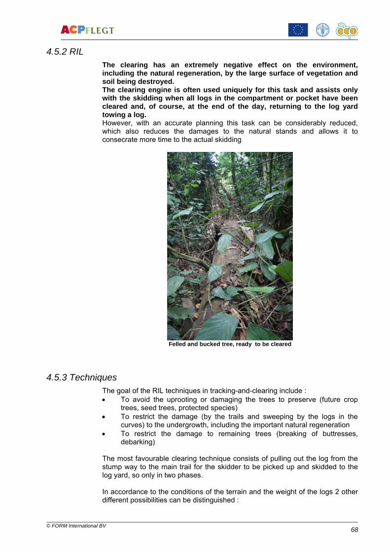
© FORM International BV
68
4.5.2 RIL The clearing has an extremely negative effect on the environment, including the natural regeneration, by the large surface of vegetation and soil being destroyed. The clearing engine is often used uniquely for this task and assists only with the skidding when all logs in the compartment or pocket have been cleared and, of course, at the end of the day, returning to the log yard towing a log. However, with an accurate planning this task can be considerably reduced, which also reduces the damages to the natural stands and allows it to consecrate more time to the actual skidding
Felled and bucked tree, ready to be cleared
4.5.3 Techniques The goal of the RIL techniques in tracking-and-clearing include : • To avoid the uprooting or damaging the trees to preserve (future crop
trees, seed trees, protected species) • To restrict the damage (by the trails and sweeping by the logs in the
curves) to the undergrowth, including the important natural regeneration • To restrict the damage to remaining trees (breaking of buttresses,
debarking) The most favourable clearing technique consists of pulling out the log from the stump way to the main trail for the skidder to be picked up and skidded to the log yard, so only in two phases. In accordance to the conditions of the terrain and the weight of the logs 2 other different possibilities can be distinguished :
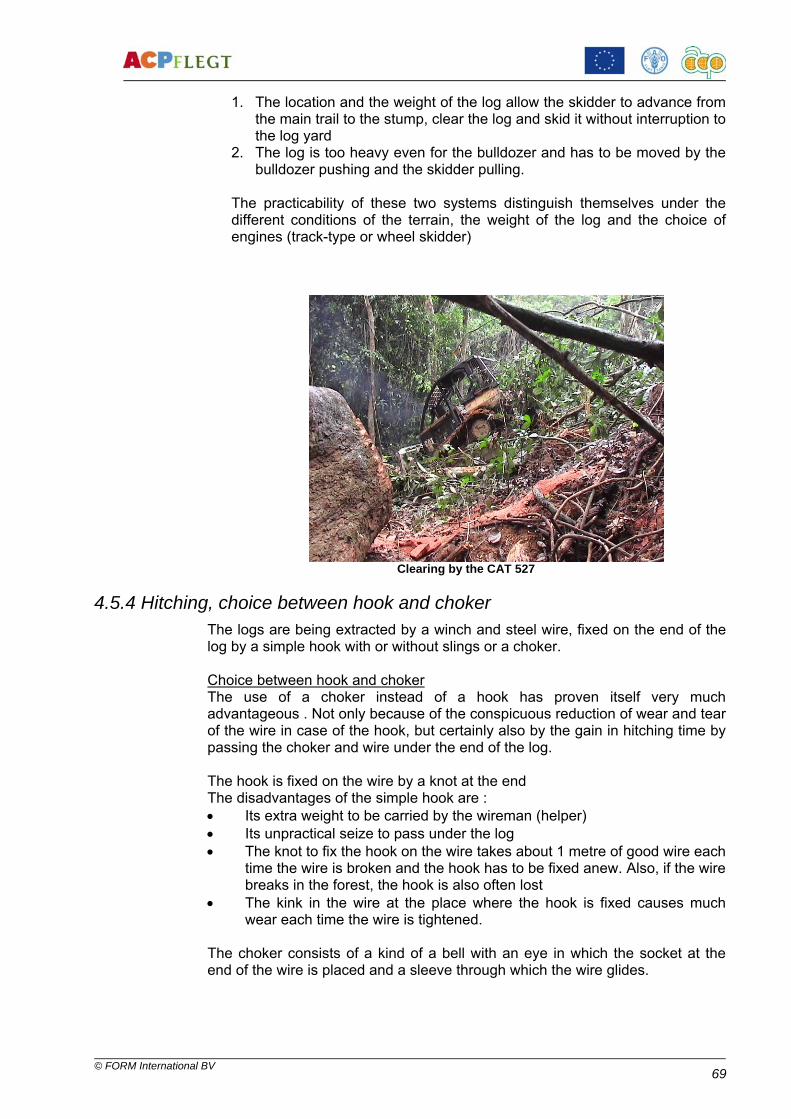
© FORM International BV
69
1. The location and the weight of the log allow the skidder to advance from the main trail to the stump, clear the log and skid it without interruption to the log yard
2. The log is too heavy even for the bulldozer and has to be moved by the bulldozer pushing and the skidder pulling.
The practicability of these two systems distinguish themselves under the different conditions of the terrain, the weight of the log and the choice of engines (track-type or wheel skidder)
Clearing by the CAT 527
4.5.4 Hitching, choice between hook and choker The logs are being extracted by a winch and steel wire, fixed on the end of the log by a simple hook with or without slings or a choker. Choice between hook and choker The use of a choker instead of a hook has proven itself very much advantageous . Not only because of the conspicuous reduction of wear and tear of the wire in case of the hook, but certainly also by the gain in hitching time by passing the choker and wire under the end of the log. The hook is fixed on the wire by a knot at the end The disadvantages of the simple hook are : • Its extra weight to be carried by the wireman (helper) • Its unpractical seize to pass under the log • The knot to fix the hook on the wire takes about 1 metre of good wire each
time the wire is broken and the hook has to be fixed anew. Also, if the wire breaks in the forest, the hook is also often lost
• The kink in the wire at the place where the hook is fixed causes much wear each time the wire is tightened.
The choker consists of a kind of a bell with an eye in which the socket at the end of the wire is placed and a sleeve through which the wire glides.

© FORM International BV
70
Use of the choker
Advantages : Gain in hitching time • The choker makes the hitching much easier as the socket of abt. 5
centimetres diameter easily passes under the log • The hitching with a choker is much faster and easier than with a hook,
which tends to slide off during the tightening • Saving wires and easy recovery of the choker • Fixing the socket (with soft solder (tin or lead recuperated from old
batteries) does not waste any length of wire. The soft solder and the socket can easily be removed from the wire by heating
• The socket of the choke ris fixed on the end of the wire the same way as the socket on the other end to fix the wire on the drum of the winch
• Considerably far less wear and tear of the wire as the sleeve through which the wire passes makes a very weak angle with the wire, creates no kink and causes far less crease.
Safety • More safety for the wireman , because once the socket is placed in the
eye of the choker, it remains there without the need to be held in place by hand.

© FORM International BV
71
Hitching with choker – CAT 527
4.6 Skidding
4.6.1 Introduction and description Skidding means the hitching of a log with a wire to the winch and extracting the log from its original position towards the log yard.. The winch of the skidding machine (D6, D7, 527 and wheel skidders) have a winch with a drum capacity of between 25 metres (for 1 inch or 25 mm wire) up to 40 metres (for 5/8 inch or 16 mm). The various engine models have been described under the paragraph « Engines used for extraction » here above. Le débardage consiste en l’accrochage de la bille au câble et en sortir celle-ci de sa position initiale vers le parc. La plupart des engins de débardage sont pourvus d’un treuil avec une bobine pouvant contenir entre 25 mètres (câbles de 25 mm) à 40 mètres (câbles de 16 mm). Les divers modèles d’engins ont été décrits sous le paragraphe 5.1.1. The goal of the RIL techniques is to reach a maximum restriction of damage to the soil and vegetation, such as : • Soil compacting • Erosion • Destruction of the original structure (by spinning, creation of gullies • Knocking down or uprooting of trees to be preserved (FCT’s, seed trees,
protected species) • Damage to the undergrowth and natural regeneration (by opening trails
and sweeping of logs through curves) • Damage to residual stands (debarking, damage to buttresses). The methods to arrive at these restrictions have been discussed here above. The ideal skidding distances are generally 500 – 600 metres for track-type tractors (D6, D7 or equivalent) and 1000 – 1200 metres for skidders (527, 535, 545 or equivalent). These distances have to be considered in relation to the road construction costs : basically, the longer the (cheaper) skid trails, the shorter the (more

© FORM International BV
72
expensive) roads to be constructed. Road construction in slopey areas, difficult and therefore costly will justify longer skidding distances than road construction in flat and dry areas. In dry season the branches opened often are not of a better quality than improved main skid trails, without any drainage, levelling or shade tree felling, because of the lack of rainfall, the deck being easily compacted by the passing timber trucks.
Skidding with CAT 535
4.7 RIL techniques
4.7.1 At establishment of log yard Severe limitation of the surface Choice of a flat terrain, but with a slight slope for drainage Careful removal of the humus topsoil and storage on a safe place (farthest
corner of the yard) to be spread after the operation Establishment of a drainage of rain water into the bushes to avoid puddles
that can turn the yard into mud.
4.7.2 At opening of skid trails • Sound planning of the main trails : - To follow, where possible, the summits of ridges - To descend or climb strong slopes as much as possible slantwise
to restrict erosion - To plan the length of the main skid trail in relation to the
concentrations of trees to be felled, to the secondary trails and to the distance to the yard
• Practical rules of the thumb :
- Clearing distance as short as possible at the expense of the side trail

© FORM International BV
73
- Maximum skidding distance for the skidder (wheel- or track) in very hilly terrain : 500 – 600 metres, on relatively flat land 1000 metres
- Maximum skidding distance with the bulldozer in very hilly terrain 200 – 400 metres, on relatively flat land 500 – 600 metres
• To restrict to a minimum the total length of the skid trail net • To restrict to a minimum the width of the trails • Vine cutting over the width of the dozer blade • Crosscutting of dead trees fallen across the traced trail • Opening with the blade : removal of the vegetation by holding the blade
just above the soil and by uprooting all trees and shrubs < 30 cm diameter
• Holes created by the uprooting to be levelled • To avoid earth movement on the trails where possible • The direction of the clearing trails must, where possible, lead uphill. • On slopes ≥ 30% trails shall be opened on the flank of the slope • To restrict the crossings of water courses to a strict minimum • The bed of water courses to be crossed must be covered with billets,
that shall be removed again when the compartment is abandoned
4.7.3 At clearing • To avoid to deviate from the traced trail • Where possible to approach the stump to max. 15 metres and to pull the
wire by hand up to the log • Use slings, where possible • To clear only at the butt or top end of the log, the one closest by and at a
feeble angle on the trail • To clear only the log end at the side of approach • Once the first log has been removed, the helper can easily reach the
end of the second log • The use of a choker instead of a hook makes in most cases the lifting of
the log end to pass the cable (and hook) under the log end redundant .
4.7.4 At skidding • To avoid to deviate from the traced trail • When climbing the hill without load, to give priority to the descending
skidder with load • Before starting to winch or to skid, lift up the log end up to the point
where the choker or hook touches the guide roll of the arch • To avoid as much as possible spinning of the tyres or tracks by using
the proper speed, the differential lock and to start winching at the right moment
• To respect the trees marked for protection • To carefully cross water courses to avoid the log end digging into the
bed or in the opposite bank (if necessary to winch the log across) • To stop skidding during heavy rain shower to avoid the creation of tracks
on the trail that can cause heavy erosion and hinder the negotiability of the trail.

© FORM International BV
74
4.8 Safety
The dangers for the workers assisting with the extraction are many : • The engine can push down with its blade vegetation and small trees and
pull vines that rip off branches from the canopy that can fall on the head of workers nearby
• The engine can reverse with out the operator noticing a person behind it • The engine can advance in the undergrowth without the operator noticing
a person in front • When skidding a log this one can sweep with its entire length through a
curve hitting people in the undergrowth on the side of the trail • It is imperative that the operator at all times is informed of the presence of
a person in the surroundings of his engine by that person himself. This person is in the first place responsible for his own safety
• For that reason, each person that has one way or the other to do with the extraction must know and apply the safety regulations related to this operation
• The operator of the engine himself is responsible for the safety of his wireman, who must place himself sometimes into a dangerous position and that out of sight of the operator
• The operator shall never start his engine nor its winch, nor its blade without having assured himself of the safe position of his helper
• As a matter of fact, with the new RIL skidding techniques the wireman plays an important role in directing the engine and must therefore stay in uninterrupted contact with the operator.
Safety provisions, materials and measures Provisions on the skidding engine : • ROPS (Rolling Over Protection) and FOPS (Falling Objects Protection)
with heavy wire mesh • Hooter • Rearviewer • Reverse beeper • Simple first aid box • Fire extinguisher Personal safety outfit: • Operator
Safety helmet compulsory Whistle
• Wireman / helper, compulsory : Safety helmet Whistle Industrial gloves Safety boots Reflecting safety jacket
• Clerk Safety helmet Whistle Safety boots Reflecting safety jacket

© FORM International BV
75
• Tracers, tree selectors Safety helmet Whistle Safety boots Reflecting safety jacket Simple first aid box

© FORM International BV
76
5. LOG YARD OPERATIONS
5.1 Introduction and interpretation of log yard operations and relevant RIL techniques
The negative effects of the log yard operations can be listed as follows : • Total removal of the vegetation and the topsoil • Intense compacting by the multiple passing of engines and heavy logs • Pollution of the soil by spilled fuel and lubricants and by industrial and
human waste
Waste of old engine oil on the log yard
At the same time the log yard operations can have a positive effect on the yield of logs and engines and by that reduce the negative impacts on the forest. We mention : • Increase of the yield of the wood by correct measuring and crosscutting • Preservation of the quality of the wood by the application of S-hooks and
(prudent) use of biodegradable insecticides and fungicides • Increase of the efficiency of the operations, thereby restricting the
operational costs and costs of wear-and-tear and consumption Each operation on the log yard has its own specific techniques in the interest of quality, efficiency and environment. These techniques are treated in the below paragraphs : • Construction of the log yard • Crosscutting of the trees into logs • Log treatment • Log measurement and marking • Handling of logs, fuel and lubricants • Loading techniques • Log administration • RIL and safety measures
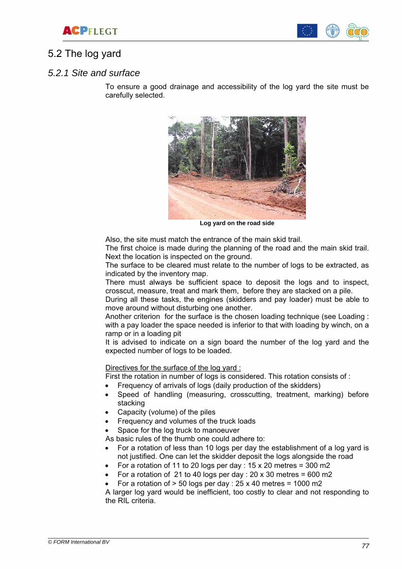
© FORM International BV
77
5.2 The log yard
5.2.1 Site and surface To ensure a good drainage and accessibility of the log yard the site must be carefully selected.
Log yard on the road side
Also, the site must match the entrance of the main skid trail. The first choice is made during the planning of the road and the main skid trail. Next the location is inspected on the ground. The surface to be cleared must relate to the number of logs to be extracted, as indicated by the inventory map. There must always be sufficient space to deposit the logs and to inspect, crosscut, measure, treat and mark them, before they are stacked on a pile. During all these tasks, the engines (skidders and pay loader) must be able to move around without disturbing one another. Another criterion for the surface is the chosen loading technique (see Loading : with a pay loader the space needed is inferior to that with loading by winch, on a ramp or in a loading pit It is advised to indicate on a sign board the number of the log yard and the expected number of logs to be loaded. Directives for the surface of the log yard : First the rotation in number of logs is considered. This rotation consists of : • Frequency of arrivals of logs (daily production of the skidders) • Speed of handling (measuring, crosscutting, treatment, marking) before
stacking • Capacity (volume) of the piles • Frequency and volumes of the truck loads • Space for the log truck to manoeuver As basic rules of the thumb one could adhere to: • For a rotation of less than 10 logs per day the establishment of a log yard is
not justified. One can let the skidder deposit the logs alongside the road • For a rotation of 11 to 20 logs per day : 15 x 20 metres = 300 m2 • For a rotation of 21 to 40 logs per day : 20 x 30 metres = 600 m2 • For a rotation of > 50 logs per day : 25 x 40 metres = 1000 m2 A larger log yard would be inefficient, too costly to clear and not responding to the RIL criteria.

© FORM International BV
78
5.2.2 Opening and drainage of the log yard Because of the natural regeneration, erosion prevention, drainage and shelter of wildlife it is advised to open the log yard, where possible, not exactly on the roadside, but with a strip of undamaged forest of approx. 15 – 20 metres wide in between the road and the log yard, that can be entered by a short branch road. For appropriate drainage in slopey areas, it is advised to locate the yard on the crest of a ridge, but with a slight slope or near a depression, ever keeping into account good drainage possibilities. Division of the log yard The following spaces have to be created on each log yard :
• The entry to the main skid trail • The entry and exit for the logging trucks • The storage of the logs for crosscutting, measuring, grading, marking
and treatment • The piles of logs ready for transport • Space for the loading of the logging trucks • Space for the loading engine to manœuvre • Environmentally safe storage of fuel, lubricants, wires, S- hooks,
etcetera (container ?) • Space with table and bench for the clerk and for the log yard workers to
shelter (tarpaulin or container)
5.2.3 Crosscutting It has been proven that a well-considered division of the tree in logs, a correctly executed crosscutting and a careful treatment of the logs bring along an important gain in quality and volume. The increase of the yield of the felled trees brings along a higher production of the forest and consequently a reduction of the surface to be harvested in relation with the volumes needed. The division of the trees into logs must be executed by a well trained log yard clerk and it is therefore important that the forest manager dedicates daily a part of his time to the log yard operations to train and monitor his workers in these disciplines.
Lost wood because of careless crosscutting

© FORM International BV
79
5.2.4 Log treatment Restriction and prevention of cracks Some tree species have a far stronger tendency to crack or split than others. Especially species with a straight grain and those with much tension in the wood are sensitive to this. Although appropriate crosscutting techniques for wood with contraction or compression tension can up to a certain level restrict the creation of cracks or splits, it can never be entirely prevented. There are however methods to prevent the cracks and splits to extend or to widen. Certain species have such a strong tendency to crack or split, that the only way to restrict this is by strapping the log with strapping or bundling wire on both sides of the marked cut before crosscutting. This is specifically the case with Aningeria spp (Aniégré, Asanfina), Tieghemella Heckelii (Makoré, Baku) and Terminalia Excelsa (Limba, Ofram, Fraké). Other species, like most of the tropical redwoods have far less tendency to split and one can restrict the cracks and splits by applying s-hooks. These s-hooks can be made locally (at the site) with strip iron of a slightly conical section, so with a sharp edge. These s-hooks are hammered diagonally on the cracks on the face of the log and stop the crack from widening and extending.
Crack caused by a wrongly placed s-hook
Protection against insects, funi, moulds and drying in Insecticides : The pinhole beetles (Ambrosia spp.), with a length between 2 and 10 mm drill holes with a diameter between 1 and 3 mm in fresh wood. These pinholes cause an important depreciation of the quality of the log. A contagion by pinhole beetles is detected by sawdust coming out o the pinholes drilled by them.

© FORM International BV
80
Contagion by pinhole beetles
An attack by pinhole beetles that is not controlled spread very fast and can become a plague on the log yard. Once the pinhole beetles have entered the wood, it is impossible to kill them, because the liquid insecticide is stopped by the sawdust and cannot enter the hole. It is therefore imperative to prevent the contagion by atomizing the insecticide on the logs as soon as they arrive on the log yard and again after handling, when fresh pieces of bark have been ripped off. Best is to mix the insecticide with a fungicide to suppress the moulds and fungi at the same time.
5.2.5 Handling of the logs A sound organisation on the log yard increases the speed of treatment and loading, simplifies all operations and can considerably reduce the surface of the log yard to be cleared. The treated logs, measured and marked, so ready for transport, will be stacked in piles along the edge of the yard, leaving the entries and exits of both skidders and trucks free.
Log piles without crossbeams

© FORM International BV
81
This allows to keep the centre of the log yard free for the log handling, for the movements of skidders, log stacker and trucks. It is also advised to stack the logs in piles according to :
• Species, quality or destination • Group of lengths • Loading unit (quantity and lengths : on a pole trailer, the longer logs are
down, supporting shorter logs on top). Stacking logs on crossbeams facilitates the treatment with insecticides (accessible from under), slows down the contagion by insects (also termites) and fungi by a better aeration and restricts the damage to the log by the fork of the log stacker.
5.2.6 Loading of logging trucks
Articulated truck and boom trailer with standards on one side only The combined truck and trailer The loads are lashed down with wires or chains with fasteners.
• The most frequently used logging trucks are articulated combinations with an adjustable boom trailer and 4 to 5 axles, of which the truck or has 2 or 3 axles and the boom trailer 2. This combination permits the « piggy back system », whereby, after offloading, the boom trailer is loaded on the platform of the truck to return to the log yard. This system saves considerably on wear of tires and shock absorbers of the trailer
• Trailers with a flat bed are polyvalent in the sense that they can
transport logs as well as other products, such as sawn timber, seagoing containers, consumables, light equipment, etcetera. In the case of logs, 2 or more removable steel crossbeams with adjustable wedges are placed on the flat bed
• Standards on the crossbeams have the advantage of
- Faster loading - Higher possible loading height - Large quantity of smaller logs Disadvantage : Limited width of the load

© FORM International BV
82
• Adjustable wedges on the crossbeams have the advantage of - Adjustable width, even a bit outside the crossbeams - More efficient in case of large logs Disadvantages : - Limited height and number of logs (pyramid) - More difficult and slower stowage of the logs.
Crossbeams with wedges With single standard With double standards
Loading methods Self-loader An articulated truck and boom trailer with two winches with ½’’ (13 mm) or 5/8 ‘’ (16 mm) passing by pulleys over the standards of the trailer
Advantages : − Total independence of the other engines of the harvesting − Saving of a loading engine (log stacker or skidder) − Recovery of isolated logs (last logs on a log yard or logs lost along the road) − Loading alongside the road (no log yard needed) − Faster loading than with a skidder − Fast and easy lashing by the winch wires. Disadvantages : − Weight of the logs to be loaded is limited by the power of the winches and
the strength of the wires − Logs have to be aligned alongside the road by the skidder or else the truck
has to reposition itself after each log loaded − Slower loading than with a log stacker

© FORM International BV
83
Log stacker (front end loader or pay loader) The log stacker on tires or tracks is used in logging operations harvesting over 2.500 – 3.000 m3 of logs monthly. The most used models are CAT 966, 980 and 988, depending on the average weight of the logs. Advantages :
- Agility : with a maximum speed of approx. 35 km/h the log stacker can move quickly between the log yards and recover isolated logs or logs lost on the roadside. It can also assist to pull logging trucks out of a quagmire even at a longer distance from the log yard. The log stacker also moves easily around on the log yard to stack, load or balance out logs on the logging truck or remove buttresses from the yard
- Polyvalence :Equipped with a shovel, the log stacker (now : pay loader) can load tipper trucks with gravel for road maintenance or spread heaps of gravel deposited by the tipper trucks. With the loading for kit can load the boom trailer on the truck (piggy back) and assist in the forest with mayor repairs (lifting or placing a winch or an engine)
- Efficiency : A log stacker with an expert operator can load a logging truck in 15 – 20 minutes.
Disadvantages : − Purchasing and maintenance costs − Operational costs : in operations producing less than 4.000 m3/month there
is much downtime between log handling and loading of trucks.
Loading with the winch of skidder or bulldozer
Advantages : − Economizing on a log stacker − Efficient for monthly production below 4.000 m3Efficace pour des
productions mensuelles inférieures à 4.000 m3 Disadvantages : − Slow loading procedure (ranging the logs before loading, winching,
balancing the logs on the trailer with the wire) − Necessary to range the logs by load − Lost time for the skidding − Only feasible for loading on trailers without standards or standards on one
side only − Loading in pyramid, so limited number of logs Loading by a ramp
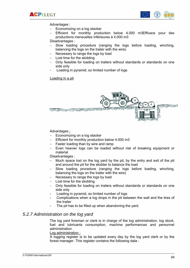
© FORM International BV
84
Advantages : − Economizing on a log stacker − Efficient for monthly production below 4.000 m3Efficace pour des
productions mensuelles inférieures à 4.000 m3 Disadvantages : − Slow loading procedure (ranging the logs before loading, winching,
balancing the logs on the trailer with the wire) − Necessary to range the logs by load − Lost time for the skidding − Only feasible for loading on trailers without standards or standards on one
side only - Loading in pyramid, so limited number of logs Loading in a pit
Advantages : − Economizing on a log stacker − Efficient for monthly production below 4.000 m3 − Faster loading than by wire and ramp − Even heavier logs can be loaded without risk of breaking equipment or
material Disadvantages : − Much space lost on the log yard by the pit, by the entry and exit of the pit
and around the pit for the skidder to balance the load − Slow loading procedure (ranging the logs before loading, winching,
balancing the logs on the trailer with the wire) − Necessary to range the logs by load − Lost time for the skidding − Only feasible for loading on trailers without standards or standards on one
side only - Loading in pyramid, so limited number of logs - Complications when a log drops in the pit between the wall and the tires of
the trailer - The pit has to be filled up when abandoning the yard.
5.2.7 Administration on the log yard The log yard foreman or clerk is in charge of the log administration, log stock, fuel and lubricants consumption, machine performances and personnel administration. Log administration : A logging register is to be updated every day by the log yard clerk or by the forest manager. This register contains the following data :

© FORM International BV
85
• Concession name • FMU • AAC • Log yard # • Page # Columns :
1. Inventory # 2. Production # 3. Felling : date, name operator 4. Bucking : date, name operator, log # 5. Extraction : date, engine # 6. X-cutting : date, measurements : log #, length, D1, D2, D3, D4, av.D,
volume, quality 7. Transport : date, waybill #
Every day the individual production sheets are collected and their data introduced into the register, so that the management can at any time monitor the production movements and stocks. If there is a digitalized stock keeping, the register is maintained at the log yard, but the same data are transferred daily to the office. An example of the logging register is attached as Annexe. Machine performances and consumption administration All operators have to keep a logbook in which the following details are noted daily : • Date • Name operator • Engine clock hours • Quantity of gasoil and lubricants consumed • Performed tasks with number of logs extracted/loaded, length road
constructed/maintained, etcetera • Breakdowns, maintenance, repairs with hours of delay. This logbook serves the technical department with monitoring the regular maintenance and the administration for the production figures. Fuel, lubricants and consumables administration For the consumption of fuel, lubricants and consumables (filters, wires, etcetera) form as in 7. ANNEXES have to be filled in by the log yard clerk responsible for the distribution. Filling up of fiel takes place at the end of each day (full tank = no condensation) topping up oil at the starting up of the engines in the morning. For a precise monitoring of the consumptions the tanks and drums have to be equipped with flow meters or, at least with calibrated dipsticks. An example of a stock book for fuel, lubricants and consumables as found under 7. ANNEXES is to updated each day.. . Personnel administration The forest personnel administration consists of keeping a roll-call book. A physical roll-call is done each morning at the arrival of the workers on the log yard and not before leaving the base. Each worker, when called by name, must identify himself visibly and answer himself to the foreman or forest manager. At the end of each day the foreman or forest manager marks the number of hours worked behind each name. All absences (justified and unjustified) as well as the overtime are marked.

© FORM International BV
86
The roll-call book is remitted timely to the head office for the preparation of the pay-roll.
5.2.8 RIL and safety measures.
Correct storage of engine oil and waste oil on the log yard
RIL measures • Surface of the log yard to be restricted to a minimum • The outline of the log yard to be demarcated with ribbon before clearing to
prevent the bulldozer to trespass. • Execute an efficient drainage • Loss of timber to be restricted by correct qualification, measuring,
crosscutting and treatment • Efficiency of the loads (volumes) to be increased • Waste oil, filters, battery acid, wires, human and industrial waste to be
collected and taken away to the base to be disposed of. • Storage of polluting products (insecticides, fungicides, acid, oils, paint,
etcetera) in a leak-proof and lockable place (sea container or lockable hut with leak-proof floor)
Correct storage of polluting products on a leak-proof floor
• Loading ramps are to be levelled (quality logs to be skidded to the next log
yard !) and pits to be filled up before abandoning the log yard.

© FORM International BV
87
Safety measures • Complete first aid box always present on the log yard • Log yard foreman or clerk qualified in first aid • Safety equipment for the crosscut operator :
- Safety helmet with visor and ear protectors - Leg protection - Safety boots - Anti-vibration gloves
• Use of wedge when crosscutting • Props and wedges under the log to be crosscut • When the log to be crosscut operator to stand uphill from the log • Spraying operator must wear the following protective gear
− Safety helmet − Gas mask − Plastic raincoat − Rubber glover − Rubber boots
• The spraying operator must not spray logs or a pile in presence of other workers
• The chemicals used must be biodegradable • All workers must stay clear of the engines manoeuvering on the log yard
(log stacker, skidders, trucks), except the engine mates (wiremen) • All engines must have a reverse claxon • All people must stay clear of a loading truck.

© FORM International BV
88
6. POST-HARVEST OPERATIONS
6.1 Introduction and description
The packet of post-harvest operations is divided in three groups of activities: 1. The administrative check, always executed by the forest manager at the
closure of each compartment, consisting of a check of the log administration and a comparison with the data collected from the different departments.
2. Physical inspection on the ground by the post-harvest inspection team, composed of an inventory clerk, also trained in monitoring the quality of sorting, clearing, felling and skidding with one or two helpers. This inspection can be done either of each compartment after closure or by sampling, for example over ¼ (each fourth compartment or pocket of the AAC). In the latter case, the representative compartments or pockets are selected by the forest manager, but should not be too far away from the actual harvesting, in case abandoned logs are to be retrieved or other tasks to be executed.
3. The post-harvest operations must be executed according to a check-list to be completed.
The post-harvest inventory team executed inspections over all departments in a single mission with the complete check-list at hand. In any case, the different points are all treated by departments in the order of passing on the ground as mentioned on the checklist under 7. Annexes. All post-harvest operations are listed per department : Inventory • Road construction (= state of maintenance, drainage, etcetera) • Tracking-and-clearing • Felling • Extraction • Log yard
6.2 Inspection of the inventory
Administrative check The list of trees numbered per compartment is compared with the felled trees in the logging register. Eventually forgotten or abandoned trees (quality, market) and felled trees, missing on the inventory are thus discovered. These trees are noted and verified by the post-harvest inventory team. Trees overlooked by the enumeration team can denote a lack of professional conscience or knowledge. Inspection on the ground • The post-harvest inspection team checks in all compartments with all the
abandoned trees that are noted by the forest manager for the reason of their abandoning (quality or other)
• In the sample compartment the team checks: − The coordinates and reference points (compass, GPS) of the
compartment and the enumeration lines (deflection ?) − The linecutting (distance, marking)

© FORM International BV
89
− Indication and respect of buffer zones − Position, species and marking on the map of the stumps − Numbering of the stumps − Marking of FCT’s − Trees rejected by the tracking-and-clearing team − Trees overlooked by the tracking-and-clearing team or by the felling
team • Report of the inspection with the check-list (7. Annexes) Operations Boundaries A line-cutting team follows the boundary lines of the AAC to re-open them and eventually renew the signs (on crossings and other limits, by paint and pickets)
6.2.1 Inspection of the road construction and waterworks In the post-harvest operations a clear distinction has to be made between permanent through-ways and roads that serve uniquely for the harvest in the AAC actually under inspection and that will be abandoned for the rest of the 30 year- cycle.
Permanent acces road with dented slope
Administrative check • To verify if the road net in the AAC has entirely and correctly been mapped • The distances found by GIS and/or on the ground by GPS or by odometer of
a vehicle have been correctly transferred onto the maps • The clock hours on the engines at the road construction as well as their
consumption and the distances completed have been correctly reported in the monthly reports
• Thus a calculation can be made of the number of clock hours and total consumption and consequently of the road construction costs per km.
• A vérifier si le réseau routier dans l’AAC a été entièrement et correctement cartographié
Check on the ground Passing on all the roads in the AAC during his last inspection ,the forest manager pays attention to the condition of the main roads, side roads, branches, bridges, culverts and drainages and the repairs affected and closes off these roads behind him by having a deep gutter dug, a large log or a heavy wire with padlock across the entrance. He writes a report of his inspection and adds this to the file of the AAC.

© FORM International BV
90
Eroded banks of a forest bridge Operations The permanent roads passing through the AAC or connecting villages or other roads are part of a regular road maintenance program : • Verification, unplugging or eventual repair of permanent drainage works (re-
opening gutters, drains, culverts) and bridges • Maintenance of the road deck(gravelling, gradering) Temporary roads are subject to the following works : • Verification, unplugging or eventual repair of drainage works (re-opening
gutters, drains, culverts) and bridges • Removal of temporary bridges and culverts • Assure the permanent free flowing of the waterways • Piercing of temporary dams • Efficiency of canopy bridges and corridors • Blocking of the entry of the temporary roads close to the junction • Signalling of the entry and interdiction to enter the site, to hunt, to farm and
to settle.
6.2.2 Inspection of tracking-and-clearing Administrative check • Comparison of the maps with the inventory and the logging register to trace
abandoned or added trees/logs Check on the ground With the inventoory map, the tracking-and-clearing map and the felling ma pat hand, the checking team verifies : • The direction of the main trail in an as straight as possible line towards the
concentration of trees the farthest away. • Verification of the connections between stumps and skid trails ((« fish bone
pattern) • The most direct connection between the main trail and the stumps • The marking by paint or ribbon of the trees to be spared and protected • The presence of enumerated trees that are not marked on the tracking-and-
clearing map • Trees marked as rejected on the tracking-and-clearing map and the reason
of rejection • Trees of commercial value forgotten on the felling map • Report of the inspection according to the check-list

© FORM International BV
91
Operations • Trees of commercial value forgotten on the felling map are marked and,
where necessary, a demarcated line is opened to the nearest trail. •
6.2.3 Felling check Contrôle administratif • At the completion of each compartment the forest manager checks in the
logging register if the lengths of the felled trees justify the number of the crosscut logs : − The total length of these logs cannot exceed the length of the felled
tree, which may indicate a wrong identification or measuring − The length of the felled tree cannot too much exceed the total length
of the logs, which may indicate that a log was abandoned. • He verifies if any numbers of trees were not filled in as felled, which may
indicate that they were abandoned or forgotten by the fellers • He verifies if any numbers of logs were not filled in as extracted, which may
indicate that they were abandoned or forgotten by the skidders • Comparison between the inventory map and the felling map • Listing the forgotten or abandoned trees and logs and markingg on a map
for the inspection by the checking team • Sending out the inspection team with list and map for verification on the
ground Check on the ground • Verification of the numbering on the stump, buttress and crown (correct
number, visible ?) • Inspection of the applied felling technique and eventual visible damage on
the stump or buttress
Bonne technique d’abattage contrôlé
• Inspection of the crosscutting at the buttress and the crown for eventual
waste. If any recovery possible, the remaining log has to be marked for extraction
• Inspection of the felling direction in relation to trees to be protected • Inspection of eventual damage to trees marked for protection • Forgotten trees of commercial value are indicated on the map • Report of the inspection according to the check-list.

© FORM International BV
92
Bad felling Operations • Trees with sufficient commercial value are yet to be felled and crosscut • Retrievable lengths on buttresses or crowns are crosscut
6.2.4 Extraction inspection Administrative check At the completion of each compartment the forest manager checks in the logging register if all logs crosscut at the stump site have actually been extractedThe logs that have not been marked as such (open space) are noted as such for the inspection team to find. The daily and monthly production and consumption reports are studied to discover eventual anomalies in the relation between production, consumption and time.
Side skid trail

© FORM International BV
93
Check on the ground The inspection team enters the compartment equipped with the tracking-and-clearing map, the felling map and the extraction map to verify the following points : • The direction of the main trail and secondary trails (also the corrected
errors) • The width of the trails shall not exceed 1 ½ x the width of the bulldozer’s
blade (no double trails, but stations for overtaking are allowed) • Correct vine cutting (no torn off branches, no entanglement of vines) • Sparing of the soil structure (no superfluous gradering or earth movement) • No unnecessary damage to the surrounding vegetation • Check of the logs marked by the forest manager as abandoned • No damage by extraction to trees marked as to be protected on the side of
the trail (too narrow curves) • Report of the inspection according to the check-list Operations • Recovery of abandoned (forgotten) logs • Levelling of the trails (filling up of the ruts) with the blade of the skidder to
reduce erosion • Digging of gutters with the blade of the skidder across the trails to reduce
erosion
6.2.5 Inspection of the log yard operations Administrative check • Check in the logging register if all logs prepared for transport have indeed
been loaded
Waste oil spilled on the ground Check on the ground • Verification of the marking of all buttresses and off-cuts and rejected
logs on the log yard • Verification of the removal of :
− Waste oil

© FORM International BV
94
− Human and industrial waste (packaging, tins, cans, plastic) − Waste steel wires − Waste oil filters − Old oil drums − Old tires − Old batteries − Steel scrap.
Well cleared and cleaned log yard Operations • Removal of
- Waste oil - Human and industrial waste (packaging, tins, cans, plastic) - Waste steel wires - Waste oil filters - Old oil drums - Old tires - Old batteries - Steel scrap.
• Filling up of the loading pit and removal of the ramp • Filling up ruts and levelling of the log yard • Eventual harrowing of the log yard • Restoring of the drainage • Spreading of the topsoil • Eventual replanting of the surface.

© FORM International BV
95
7. OBSERVATIONS DURING THE TRAINING
No. Element Observations / Problems Suggestions 1 Management 1.1 Organisation
(See list of staff)
1.2 Production
(Hierarchy, functions)
1.3 Communication
(Satellite radio, phone, fax, cell phone, internet?)
1.4 Planning
(staff in charge)
2 Office 2.1 Production
Administration (Software, system)
2.2 Personnel Administration
(system?)
2.3 Consumables Administration
( Daily reports forest to office?). (Consumption fuel, lubs?)
2.4 Stock Survey Administration
(Forest administration? software, GIS)
2.5 Cartography
3 Workshop 3.1 Organisation,
discipline
3.2 Consumables Administration
(Computerized?)
3.3 Stores 3.3.1 Fuel
(Clean floor? Spillage?)
3.3.2 Lubrificants
(Spillage?)
3.3.3 Chemicals
(Lockable? Instructions? Safety?)
3.4 Distribution consumables
(Spillage?Registration?)
3.5 Waste treatment
(Oil traps?)
3.6 Health & Safety
(safety boots, goggles , gloves, leather apron?)
3.7 Environmental measures
(Oil traps at wash bay and fuel station? Scrap?)
4 Stock survey 4.1 Opening and
marking lines (Quality?)
4.2 Alignment lines
(Compass bearings correct?)
4.3 Performances : 4.3.1 Line cutting
(Distance per man-day?)

© FORM International BV
96
4.3.2 Counting
(Surface per man-day?)
4.4 Identification and marking trees
(Maps, GIS? Paint or scribing knife?)
4.5 Judgment quality trees
4.6 Cartography
(Quality?)
4.7 Documentation
(GIS / software?)
5 Roads 5.1 Planning
(maps, GIS, stock maps?)
5.2 Opening
(Equipment? Quality?)
5.3 Leveling / gradering
(Equipment? Quality? Camber?)
5.4 Shade trees
5.5 Drainage
(Gutters? Drains?)
5.6 Bridges / culverts
(Quality, debit, safety?)
5.7 Canopy bridges – corridors fauna
5.8 Maintenance
5.9 Safety (road signs for bridges, curves, speed bumps bridges, villages, visibility in curves?)
6 Felling 6.1 Tracing trees
( yield map, yield summary, notched pickets?)
6.2 Quality judgment
6.3 Safety
6.4 Competences / techniques
6.5 RIL
6.6 Performances / bonuses
7 Extraction 7.1 Planning trails
(Maps?)
7.2 Pushing 7.2.1 Engines and
condition
7.2.2 Tracing felled trees

© FORM International BV
97
7.2.3 Opening trails
(protection FCTs and protected spp?)
7.2.4 Direction / distance
7.2.5 Hitching
( Hook or choker/slings?, cable?) (logs per trip?)
7.2.6 RIL
(tagging of FCT? Damage to vegetation and FCT(logs too long/curves too tight? leveling? anti erosion traps? vine cutting?)
7.3 Skidding 7.3.1 Engines and
condition
7.3.2 Technique (traction/winch)
7.3.3 Direction / distance
7.3.4 Efficiency
(# Logs per trip?)
7.3.5 Competence
7.3.6 Safety
(Yellow vest, hats, Safety boots?)
7.3.7 RIL
(dozering on trails?)
8 Landing 8.1 Maintenance
engines
(oil, filters, other waste on landings?)
8.2 Log treatment
(No forbidden chemicals?)
8.3 Quality judgment – X-cutting
8.4 Measuring
8.5 Qualification
8.6 Marking
(Clear? Complete?)
8.8 Log (Daily production sheets,

© FORM International BV
98
Administration
register on site, software in office?)
8.9 RIL ( waste, etc)
(Landings clean, soil loosened
9 Traceability 9.1 Marking
(Clear on stumps and logs?)
9.2 Administration
Register up to date? Software?)
10 Monitoring 10.1 Supervision : 10.1.1 Senior staff
(regular visit manager and/or co-ordinator to all concessions in operation?).
10.1.2 Junior staff on site
10.2 Bonus systems
11 Anti-poaching 11.1 Awareness
building
11.2 Announcement / notice
11.3 Regulations 11.4 Instructions
Sub-contractors
11.5 Engagement Forestry / police
11.6 Control lorries and passengers
Remarks:

© FORM International BV
99
8. ABBREVIATIONS
AAC Annual Allowable Cut, 1/5 of a Quenquennial Unit (QU) ARCView A brand of geographic information system CSM Concession under Sustainable management CITES Convention on International Trade in Endangered Species DBH Diameter at Breast Height FC Forestry Commission, the Ghana authority for forestry within the Ministry of Food and
Agriculture FCT Future crop tree FMU Forest management Unit : forestry unit for which a SFMP has been established for
one rotation of 25 or 30 years or longer, divided into 5 or 6 or more QU GIS Geographic Information System, such as ARCView or MAPINFO GPS Global Positioning System MAPINFO A brand of geographic information system MINFO Ministry of Forestry of any given country NGO Non-governmental Organization QU Quenquennial Unit, 1/5th of a FMU, divided into 5 AAC RIL Reduced Impact Logging SFM Sustainable Forest Management SFMP Sustainable Forest Management Plan TUC Timber Utilisation Contract: concession rights given to a timber contractor under
condition of the rules for sustainability as established by the FC

© FORM International BV
100
9. SELECTED REFERENCES
Centre technique forestier tropical : Recueil technique de l’exploitation forestière, 2ième partie (1960 –1970)
Food and Agriculture Organization : Code régional de l’exploitation à faible impact dans les forêts tropicales humides d’Afrique centrale et de l’Ouest (2003)
Hout, P. van der : Forestry Training Centre, Guyana : Course in Peduced Impact Logging Pasquier, J.-M. - et Jeanmart, - Philippe: Normes et Méthodes de Travail CEB (2002) Keller, G. & J. Sherar : Low-volume roads engineering (2003) Vroom, M. : The application of Reduced Impact Logging in forest operations in West Africa (2000)
Vroom, M. : Extraction of roundlogs – Planning and techniques with RIL measures (2000)

© FORM International BV
ANNEX 1 CHECK-LIST ASSISTANCE TO MANAGEMENT IN RIL
Company name: Site : Dates :
Management: Type of training:
Initial training Refresher course
Persons taking part in the training:
Name Function
Agenda : Day Elements Site

© FORM International BV
ANNEX 2 FUEL AND LUBRICANTS ISSUE SHEET
Fuel clerk :
Date Engine Location Clock Gasoil Engin
Oil TransmOil
Hydr. Oil
Remarks
Totals
Verified: Date:

© FORM International B.V.
ANNEX 3 LOGGING REGISTER
LOGGING REGISTER Concession: Compartment Inventory Felling Extraction Measurement Transport Stock # Specie Tree # Date Operator Log
# Date Operator Engin
e Length D1 D2 D3 D4 Av Volume Qual Date W/Bill Truck
nr Total logs: Total volume:

© FORM International B.V.