training document for biogas mason - ttp … document for biog… · biogas plant”. project’s...
TRANSCRIPT

1
MINISTRY OF AGRICULTURE AND RURAL DEVELOPMENT - MARD
THE NETHERLANDS DEVELOPMENT ORGANIZATION - SNV
SUPPORT PROJECT TO THE BIOGAS PROGRAMME FOR ANIMAL
HUSBANDRY SECTOR IN VIETNAM
TRAINING DOCUMENT
FOR BIOGAS MASON
HA NOI - 2007

2
FOREWORD
Biogas technology has been introduced in Vietnam since early 1960s. Up to
now, the technology has been further improved and applied with different scales.
Biogas technology has brought about remarkable economic and social benefits to
households. Domestic biogas plants have contributed to reduce environment
pollution due to animal waste and at the same time to provide alternative energy
for fuel, lighting, warming animal, ect.
With the benefits of the technology, project “Biogas program for the
Animal Husbandry Sector in Vietnam” was designed with objectives of
developing a commercial viable biogas industry and reducing the use of fossil
fuel. The project is implemented by Ministry of Agriculture and Rural
Development in cooperation with the Netherlands Development Organization –
SNV.
In order to provide useful information on biogas technology to project
participants, especially to mason, Biogas Project Division has prepared and
published first edition of “Biogas Technology – Mason training document” in
2003. After receiving feedback and comment of provincial management boards
and readers, the second edition is published with supplement contents and new
title of “Training Document for Biogas Mason”. This document is for internal
circulation only. We would like to introduce the book and hope to receive more
constructive comment from readers for perfect edition.
Nguyen Thanh Son
Vice Head of LPD
Project Director

3
ABBREVIATION
AWG Daily weight gain
BPD Biogas Project Division
GHG Greenhouse Gases
HAU Hanoi Agricultural University
LPG Liquefied Petroleum Gas
MARD Ministry of Agriculture and Rural Development
NIAH National Institution of Animal Husbandry
PBPD Provincial Biogas Project Division
PVC Polyvinyl Chloride
QC Quality Control
SNV Netherlands Development Organisation

4
Part I
INTRODUCTION ON “SUPPORT PROJECT TO THE
BIOGAS PROGRAMME FOR ANIMAL HUSBANDRY
SECTOR IN VIETNAM
AND
MASON TRAINING COURSE

5
I. Project introduction
1. Project overview
Support Project to Biogas Program for the Animal Husbandry Sector in
Vietnam is implemented by Livestock Production Department (under MARD), in
cooperation with Netherlands Development Organisation – SNV. Program has
been started since 2003 with overall goals of further developing the commercial
and sustainable deployment of domestic biogas; and avoiding the use of fossil
fuels and biomass resource depletion.
The project is implemented in three phases:
- The phase I, (1/2003 - 1/2006): the project was implemented in 12 provinces with a 2.5 million Euro grant from Netherlands government, and
covered 12 provinces nationwide;
- The bridging phase, 2006: the preparatory period for phase II; and
- Phase II (2007 – 2010), the project will be deployed in 50 provinces
nationwide.
In the period of 2003-2006, the project has supported construction of 27.000
biogas plants, providing trainings for 300 provincial and district technicians, 600
mason teams and 27,000 households, and creating 1,400,000 working days for
rural labour.
The second phase of project will be carried out in 4 years (2007 – 2010). By
the end of 2010, the project will complete 140,000 biogas plants and make
contribution to reduce 420,000 tons of CO2 per year, to provide clean energy
equivalent to 545,000 tons of firewood, 33,600 tons of charcoal, 6,020 tons of
petrol and 6,450 kg LPG. In this phase, the project will benefit 700,000 farmers,
provide training for 600 biogas construction enterprises and create 1,400,000
working day for rural labour.
The project also makes contribution to livestock waste treatment, reduction
of firewood use, improvement of community health and reduction of workload
for women and children.
The project was awarded with Energy Globe Award 2006. This is the most
acknowledged award in the world for projects making contribution to reduce the
global warming.
2. Project objectives

6
The main objective of project is “Improve income and living standard of rural
households in Vietnam via exploiting maket and non-market benefits of domestic
biogas plant”. Project’s objective is also in line with policy and priorities of
government and sectors that are stated in Decrees on rural and agriculture
development. It is also in the right track with policies on economic structure
transition and agricultural product comsumption.
Basing on the above objective, the overall objective is “to develop a viably
commercial viable biogas sector”
Project is implemented in the coming 4 years in over 50/64 cities/provinces
nationwide with more than 800,000 beneficiaries. The specific objectives of the
project include:
- Continue the programme operations in 24 provinces in 2007 and start in
another 31 to build a total of 140,000 plants.
- Provide training for at least 1 provincial biogas technician, 1 district biogas
technician and 2 biogas mason teams per district, and support to establish 1-2
biogas enterprises and a biogas programme office per province;
- Provide three training courses for all biogas users (pre and post construction
training and extension trainings are integrated);
- Contribute to reduce environment pollution due animal husbandry
development and improve sanitation on the farms;
- Reduce the time spent on firewood collection, cooking and cleaning.
- Reduce GHG emission with about 700.000 CO2eq tons/year (in 10 credit
years that equivalent to 7 million tons of CO2) and produce good fertilizer for
cropping and food for animals;
- Substitute yearly about 293.000 tons of agricultural waste/377.000 tons of
firewood/ 3.100 tons of charcoal/43.000 tons of antracide/7.800 tons of petrol or
5.600 tons of LPG with clean energy source in order to improve livelihood
environment and health in rural areas;
- Create at least 1.400.000 labor days for “biogas plant construction and
services” in rural areas.
II. Objective, target group and program of mason training

7
1. Objective and target group of mason training
a) Objective
Overall objective: Mason training course aims at providing mason with basic
information on biogas technology such as structure and operation of biogas plant,
construction steps, biogas plant operation and maintenance and quality control.
Specific objective:
General introduction of project and biogas technology as well as benefits
and responsibilities of biogas mason;
Construction steps of fixed dome biogas plant;
Instruction on biogas appliances installation;
Instruction on operation and maintenance of fixed dome biogas plant;
Popular breakdowns in biogas plant operation and maintenance.
Safety related issues during construction, installation, quality control,
operation and maintenance of biogas plant.
b) Target group
Target groups of the training are skillful local masons who are selected by
provincial biogas project divisions. These selected masons should have at least 2
year-experience in civil construction. Those experienced with biogas plant
construction are preferable.
2. Document structure and content
The training document consists of 3 parts. The first part gives introduction on
Project “Biogas Program for the Animal Husbandry Sector in Vietnam”; training’s
objectives, target group and program as well as role and responsibilities of project
mason. The second part includes 9 training modules on biogas technology, plant
selection, construction, quality control, operation and maintenance. The third part
instructs practice at site.
3. Benefit, role and responsibilities of biogas mason
a) Role
- Directly construct the biogas plant and;
- Ensure the construction progress and quality of biogas plant.

8
b) Responsibilities
- Participate in all sections of mason training;
- Follow technical requirements during the construction of biogas plant;
- Provide warranty for biogas plant in 1 year from the acceptance date;
- Provide deposit of 1 million dong for provincial biogas project division.
c) Benefit
- Be trained free of charge and provided with practice licence;
- Participate in project activities such as experience exchange workshop,
refresh training, ect.
- Be provided with technical support and project related technical training.
3. Program
- Duration: 7 – 9 days including:
+ Theory: 2 days
+ Practice: 5-7 days (depending on location of expected plant and professional
of mason team)
Mason training program
Method Time Content
Theory Day
1
07.30-08.00 Opening ceremony
08.00-08.20 Part 1: Introduction on Biogas project and mason training
08.20-08.50 Part II: Training Modules
Module 1: Introduction on Biogas technology
08.50-09.10 Module 2: General introduction on Fixed-dome biogas plant
09.10-09.25 Tea-break
09.25-10.30 Module 3: Selection of fixed dome biogas plant
10.30-11.45 Module 4: Construction fixed-dome biogas plant
11.45-13.30 Lunch
13.30-14.30 Module 5: Installation pipe line, operation and maintenance
of biogas appliances
14.30-14.45 Module 6: Operation and maintenance of biogas plant
15.45-17.30 Practice on the location
Build foundation of the digester
Practice Day 2 Practice on 04 biogas plants

9
Method Time Content
Requirements of construction materials
Define plant area; define levels
Define centre, radius of biogas digester
Make truncated-cone-shaped cover of digester
Construct wall of digester
Day 3
Practice on 04 biogas plants
Construct wall of digester (con’t)
Define inlet and outlet of digester
Construct dome of biogas digester
Day 4
Practice on 04 biogas plants
Construct dome of biogas digester (con’t)
Construct collar of digester
Day 5
Practice on 04 biogas plants
Define bottom height level and overflow pipe
Construct compensation tank and mixing tank
Mortaring, painting and anti-impregnating
Day 6
Morning
Back - filling
Practice testing water-tight and air-tight
Install gas-pipe system, pressure-gauge
Install gas appliances
11.30-13.30 Lunch
13.30-17.00 Site visit
Theory and
Practice
Day 7
07.30-07.45 Module 7: Project standards
07.45-08.45 Module 8: Quality management
08.45-09.45 Module 9: Bio-slurry utilization
09.45-10.00 Tea-break
10.00-10.45 Q&A
10.45-11.45 Test
11.45-13.30 Lunch
13.30-14.00 Answers for test
14.00-15.00 Evaluation on organization, trainers and participants
Certificate issuance

10
Part II
TRAINING MODULES

11
Module 1
OVERVIEW ON BIOGAS TECHNOLOGY
I. General concept
Organization thing (animal, plant…) is mainly formed by organic matters.
These organic matters are decayed under the action of microorganisms. This
process is called digestion process. There are two distinguisable processes.
- Aerobic digestion process (with presence of oxygen) occurs in an oxygenic
environment,
- Anaerobic digestion process (without presence of oxygen) occurs in an
oxygen-absent environment.
The latter generates a mixture of gases called biogas that contains two main
components of carbon dioxide (CO2) and methane (CH4). Methane is
combustible gas; therefore biogas is also cumbustible gas.
II. How biogas is generated?
In nature, biogas is generated at deep water, where oxygen is absent like
stagnant swamps (swamp or marsh gas), at the bottom of ponds, lakes, deep
wells, flooded paddy fields, rubbish dumps (dump gas) or even in the digestion
system of human and animal (intestine gas).
Biogas is also generated in coal mines (mine gas), oil wells (gas) and through
many changes in the geological time of million years.
Under artificial condition, biogas is generated in biogas plant in the anaerobic
fermentation proces.
III. Composition and characteristics of biogas
1. Composition of biogas
Biogas is a gaseous mixture. The composition of biogas varies with raw
materials and conditions for digestion process like temperature, pH value, water
quality etc. It also depends on fermentation stages. Table 1.1 shows the
composition of biogas.
Table 1..1. Composition of biogas
Composition Proportion (%) Composition Proportion (%)
Methane - CH4 50 - 70 Hydrogen - H2 0 – 3
Carbon dioxide - CO2 30 - 45 Oxygen - O2 0 – 3
Nitrogen - N2 0 - 3 Hydrogen sulphide - H2S 0 – 3

12
a) Methane
The main component in biogas is methane, which occupies the highest ratio
of the volume. Methane is also the main component of natural gas (normally
more than 90 percent). Methane is a gas without colour and odour, lighter than
air and less dissolved in water. Methane is liquefied at temperature of minus
161.5 Celsius degree under atmospheric pressure. Therefore both methane and
natural gas should not be liquefied due to its liquedification process consumes a
lot of energy.
b) Carbon dioxide
The second main component of biogas is carbon dioxide (CO2). It is a
colorless gas without odour, 1.5 times heavier than air and non-combustible gas.
The high content of carbon dioxide in biogas will reduce quality of biogas.
c) Hydrogen sulphide
Hydrogen sulphide (H2S) accounts for very small portion in biogas. It is a gas
without colour and has typical foul smell that led to smell biogas. The content of
hydrogen sulphide, that causes inconvenience, in biogas will be higher when
human faces and chicken dung is used as fermentation material than that
produced from others. However, hydrogen sulphide is combustible gas, too.
Therefore, odour will disappear when burning. Hydrogen sulphide is poisonous
gas. Exposing much to hydrogen sulphide causes dizziness, headache, vomiting
and unable to smell others.
2. Characteristics of biogas
Biogas is usually fully saturated with water vapor. This vapor will be
condensed into water in pipeline thus should be let out.
Biogas with 60 percent of methane and 40 percent of carbon dioxide has
density of 1.2196 kg per cubic meter and specific gravity of 0.94. Thus, biogas is
lighter than air.
Biogas has the heat value of 4.800 Kcal/m3
IV. Terminology defined in the sectoral standard 10TCN 97 - 2006
1. Biogas plant: is the whole system consisting of biogas digester, gas
conveyance and gas using appliances.

13
2. Digester: is the main component of biogas plant for retaining the
feedstock and ensuring the appropriate conditions for the anaerobic digestion
process to take place smoothly.
3. Compensation tank: is a component of biogas plant to do the task of
creating gas pressure by retaining effluent coming out from digester when gas is
produced.
4. Fermentative fluid: is fluid environment in digester where digestion
process happens.
5. Bio-slurry: A by-product of solid and liquid form which is produced from
decomposition process of substance. Bioslurry comprises three elements called
biogas digested effluent, solid residue and scum.
Biogas digested effluent: liquid flows from digester to compensation tank.
Solid residue: solid lies on the bottom of digester.
Scum: solid floats on the surface of fermented fluid in digester.
V. Benefits of biogas technology
1. Benefit in terms of clean energy
Biogas with high energy can be used for variety of purposes:
* Cooking: like the use of liquefied petroleum gas (LPG)
* Lighting: as biogas can be burnt to produce dazzling light like that of
kerosene mantle lamp.
* Running internal combustion engines: replace petroleum and diesel;
running milling device, pump or power generator.
* Running refrigerator, hatching machine…
* Warming chicken, breeding silkworm and warming greenhouse…
In addition, biogas can be used to preserve vegetable, fruit and cereal
products.
2. Benefit in terms of mitigating environment pollution
* Improve sanitation:
- Cooking with biogas reduces smoke and heat, therefore reduces diseases
relating lung and eye.
14
- In digester, there is no favourable environment and condition for the
development of pathogens and eggs of parasitic worms. They are almost killed
after long digestion process.
- Bio-slurry can be used as fertilizer and pesticide.
* Protect soil from infertility or erosion,
* Reduce deforestation
* Protect atmosphere and reduce greenhouse gas emission.
3. Provide organic fertilizer and animal feedstock
Bio-slurry is very rich with nutrient content, especially amonia N (NH4+)
and vitamins... thus it has good effects on soil improvement, erosion resistance,
humid content increase etc, hence especially good for crops and being additional
feedstock for pig and fish.
- Bio-slurry can inhibit the development of some plant diseases and pests like
spot leaf on rice and wheat, rotten disease on sweet potato.
- When bio-slurry applied for paddy rice, it can control significantly trunk
pest, green leaf hopper, grey leaf hopper, leaf roller, spot leaf.
As the result, the use of bio-slurry for the prevention and control of crop
diseases and pests can reduce the amount of pesticide used and alleviate the
pollution of the environment. Therefore, bioslurry can be considered as clean
fertilizer which helps control diseases and pests for crops.
4. Other benefits
* Mordernize rural areas
* Liberate women and children from housework and hard firewood collection
* With the deployment of biogas technology, a new profession is created so
as to generate more jobs for people.
* The use of biogas as substitution for kerosene, chemical fertilizers and
pesticides will help the nation save a lot of foreign currencies spent on importing
kerosene and chemical products.
* The use of bioslurry as fertilizer improve soil quality, increase fertility and
reduce erosion, hence soil resource is preserved.
VI. Fermentation material for biogas production
The materials can be classified into two kinds: material with animal root and
material with plant root.

15
1. Animal material
Animal material includes animal waste (dung and urine) of cattle, poultry and
human excrement.
The amount of waste matters per head depends on body weight and
nutritional regimen. Table 1.2 shows the average amounts of excrements
discharged by human beings and animals per day.
Table 1.2. Amounts of human and animal wastes discharged per day
Kinds Body
weight (kg)
Amount of waste by percent of body weight Amount of fresh
dung (kg/day) Dung Urine
Cow 135 - 800 5 4 – 5 8
Buffalo 300 - 500 5 4 – 5 12
Pig 30 - 75 2 3 2
Goat/sheep 30 - 100 3 1 – 1.5 3
Chicken 1.5 - 2 4.5 0.08
Human 50 - 60 1 2 0.5
Owing to the work of the human or animal digestive system, the excremental
materials decompose easily and produce biogas rapidly. However, their
fermentation periods last for a rather short time (about two to three months) and
the yield of biogas by a kilogram of waste is not much.
Cattle dung, pig excrement decompose more rapidly than that of poultry and
human beings’, yet the yield of biogas produced from poultry and human
excrement is much more.
2. Plant material
The plant materials refer to the leaf and stalk of graminaceous plants like
agricultural residue (chaff, straw, leaf and stalk of maize, potato, bean etc.),
organic waste (vegetable, fruit and foodstuff refused etc.) and wild hydrophytes
(water hyacynths, alligater weed, water lettuces…). Wood and old plants
decompose hardly thus they are not as fermentation materials.
The decomposition period of plant-root materials is longer than that of
animal type materials. Hence, materials from plants should be fed by batch
feeding and each batch may be kept by the period of from three to six months.
3. Practical yield of biogas by materials
16
Table 1.3. Characteristics and yield of biogas by some common fermentation materials
Fermentation material
Amount of waste per day (kg/animal head)
Dry matter content (%)
Carbon/nitrogen (C/N) ratio
Gas yield of the feedstock
(liter/kg/day)
Manure
Cow 15 - 20 18 - 20 24 - 25 15 – 32
Buffalo 18 - 25 16 - 18 24 - 25 15 – 32
Pig 1.2 – 4.0 24 - 33 12 - 13 40 – 60
Poultry 0.02 – 0.05 25 - 50 5 - 15 50 - 60
Human 0.18 – 0.34 20 - 34 2.9 - 10 60 - 70
Plant
Fresh water hyacinth
4 - 6 12 - 25 0.3 – 0.5
Dry paddy straw 80 - 85 48 - 117 1.5 – 2.0
The yield of biogas is calculated by the amount of feeding materials per day
(liter/kg/day). Animal excremental materials are fed in the digester in regular
quantity each day. Plant materials are fed in the digester by bactch-fed feeding.
Table 1.3 shows us the reference data for some common fermentation materials.
4. Feeding process
There are two feeding processes: continuous feeding and batch feeding.
a) Continuous feeding
Fermentation material is charged full before putting biogas plant into
operation. After that, material is fed into digester daily meanwhile the same
amount of digested material is discharged or taken out from the digester to create
place for new material. This feeding is suitable for decent ration material in time
such as animal and human excreta.
b) Batch feeding
In this feeding, a whole batch of material is put into the digester at a time.
During the fermetation process, a new material is not fed into digester. After
fermentation is completed and gas is used up, all the residue is taken out and
then the digester is fed with another batch of materials.
This feeding is adopted for the plant fermentation materials as they have
long digestion period, each batch can last for a period of three to six months.
VII. Factors affecting biogas production
The generation of biogas is affected by a great number of factors. We will
look at the most factors affecting the construction and operation of biogas
plant so as to ensure the best operation and biogas production as expected.

17
1. Anaerobic environment
Biogas fermentation requires the involvement of strict anaerobes. Among
them, the methanogenic bacteria are the most important ones. These bacteria
merely live in the extremely non-oxygen environment. Hence, it is the first
important factor to ensure an extremely oxygen-absent environment.
2. Temperature
Action of methane producing bacteria is strongly affected by temperature. Ideal
temperature in operation of simple digester is about 35-Celsius degrees. The yield of
biogas reduces significantly when the temperature drops and the fermentation process
will stop if temperature drops under 10-Celsius degrees.
Therefore, it is important to keep digester warm in winter; even in the places
where the ambient temperature is rather low biogas digester should be insulated. Thus,
have the biogas plant built underground is the good way to keep the ambient
temperature of fermentation environment.
3. pH value
The optimal pH for the action of bacteria is in the range of 6.8 to 7.5, i.e. the
light alkaline environment. However, methane producing bacteria is still growing
in pH value in the range of 6.5 to 8.5.
4. Property of fermentation materials
- Total solid content
The optimum total solid content of biogas decomposition is in the range of 7 –
9 percent. If the feedstock is water hyacinth, the optimum total solid content is 4-5
percent. In case of paddy straw, it is 5-8 percent. The total solid content of raw
materials is usually higher optimum value for fermentation process; therefore,
water should be added into digester. The appropriate dilution ratio is 1 – 3 liters of
water to 1 kg of fresh material.
- Carbon – nitrogen ratios of fermentation materials
Carbon – nitrogen ratios is an important index to evaluate the capacity of
decomposition of fermentation materials. Generally speaking, biogas microbes
consume carbon thirty more than nitrogen. Thus the optimum carbon – nitrogen
ratio of feedstock is 30/1. Materials with low carbon – ratios start fermentation
more quickly than those with high carbon – nitrogen ratios, and moreover the
latter are likely to acidify and bring about the failure of fermentation as the high
concentration of NH3+ in the fermentative fluid is an inhibitor to bacteria.
In general, the carbon – nitrogen ratios of cattle and pig are suitable while
that of human beings and poultry is low. The carbon – nitrogen ratio of plant is

18
high and this ratio is getting very high with old plants. Therefore, the materials
with different carbon-nitrogen ratios should be used in proper proportions to
ensure suitable ratio for biogas fermentation.
5. Retention time
Retention time is the time for keeping fermentation material the digester.
This is also the period for biogas produced.
Under conditions of Vietnam, retention time of animal waste is defined in the
Sectoral Standard 10 TCN 97 – 2006 as shown in table 1.4.
Table 1.4. Retention time according to sectorial standard
Region Mean temperature in winter (OC) Retention time (day)
I 10 - 15 55
II 15 - 20 40
III 20 30
Retention time for plant materials is 100 days.
6. Inhibitors and toxicity
The action of biogas bacteria is affected by some inhibitors and toxicants. When
the concentration of these matters exceeds a certain limitation, bacteria will die.
Therefore, these matters are not allowed to present in fermentative fluid.
In practice, there must be no fill of the toxicants such as pesticide, herbicides,
antibiotic, soapy water, dye, oil into digester.
Table 1.5. Optimum conditions for biogas fermentation process
No. Factor Optimum value
1 Temperature (OC) 35 - 40
2 pH value 6.8 – 7.5
3 Retention time - Manure
- Plant
30 - 60
100
4 Solid content - Manure
- Plant
7 - 9
4 - 8
5 Carbon – nitrogen ratio 30/1

19
Module 2
BASIC INTRODUCTION ON
FIXED DOME BIOGAS PLANT
I. Structure and clarification
1. Structure
Domestic biogas plant is digester with simple structure and continuous
feeding mechanism. The plant is constituted from 6 main parts: 1) Mixing
tank; 2) inlet pipe; 3) digester; 4) outlet pipe; 5) compensation tank and 6) gas
pipe.
a) Mixing tank: is place to discharge feedstock
b) Inlet pipe: has function to lead input materials to digester. The pipe is
of cylindarial shape, made of concrete or hard plastic with inside diameter of
150mm
c) Digester: is the main part of biogas plant. Slurry is contained and
fermented in the digester for biogas production.
d) Outlet pipe: also has similar structure and made of the same material as
inlet. However inside diameter of outlet can be smaller than or as big as inlet
since effluence is liquid substance.
e) Compensation tank: is of dome shape and has function to regulate gas
presure in digester. Besides, this tank also contains bio-slurry and act as a
valve to protect digester.
f) Gaspipe is made of steel or hard plastic. One end of gasholder is
connected to gas pipe and the other end links with digester to collect and
transport gas out of digester.
2. Classification
According to the shape of digester, there are 3 types of biogas plants. They
are: parallelepiped pattern, cylindar pattern and sphere pattern.
a) Cylinder pattern
- Advantage: Construction technique is familiar
- Disadvantage:
+ More materials are needed since the digester is bigger and wall is thicker,
the cover must be made of concrete.

20
+ The corners can crack easily since they have to bear very high pressure.
+ The corners are non-operation places, therefore real operation volume is
smaller than constructed volume.
There are two types of this pattern: Nguyen Do type as figure 2.1 and RDAC
type as figure 2.2
Figure 2.1. Nguyen Do type Figure 2.2. RDAC type
b) Cylinder pattern
- Advantage:
+ Construction technique is familiar.
+ Saving construction materials.
+ Limiting the corners.
- Disadvantage:
+ It needs more materials for construction than parallelepiped pattern.
+ The dome of digester must be of sphere shape.
There are two types of this pattern: Dong Nai type and former RDAC type
Figure 2.3. Dong Nai type Figure 2.4. Former RDAC type

21
c) Sphere pattern
- Advantage:
+ Lower cost due to:
Saving construction materials due to surface area is smallest and bricks
are laid slantingly which result in best strength.
Using common materials and minimize the utilization of steel.
+ Area of sphere gas storage is smallest and without corners which helps to
reduce gas loss and avoid cracks.
+ Digesters with small surface is underground and thus it can save space,
limit the influence of low temperature outside and keep temperature stability.
+ The digestion slurry surface is always up and down, its surface area is
narrowed or expanded and therefore reduce the scum formulation.
- Disadvantage:
+ Construction technique is unfamiliar and therefore masons need to be
trained to construct it.
+ It is easy to cause gas leakage if plastering is not done well.
+ Calculation for design is complicated and requires a particular computer
program.
This pattern consists of the following types: Type of Can Tho University and
Type of Energy Institute
* Type of Can Tho university
Figure 2.5. Type of Can Tho University

22
* Type of Energy Institute (NL)
Figure 2.6. Type NL.6 of Energy Institute
d) Type KT1 and KT2
KT.1 was developed from NL-6 of Energy Institute and KT.2 was improved
from type of Can Tho University. Both these types were chosen for sample
design of Sector standards for small biogas plant issued by Ministry of
Agriculture and Rural Development.
Apart from common advantages of sphere pattern, these types also have
outstanding advantages as follows.
Advantage
- Appropriate design
- Maximum materials saving
- Use common construction materials which are available in province and
local mason can do the construction work.
- Do not rely on fabricated components; hence digester dimension can change
upon requirement
- Digester dimension is suitable with climate, quantity and feedstock as well
as demand of each household.
23
Disadvantage:
+ Complicated construction technique;
+ Some construction materials are not always available like clay which is
filled in collar to ensure the gas tight.
Figure 2.7. KT1 type Figure 2.8. KT2 type
II. Operation of fixed dome biogas plant
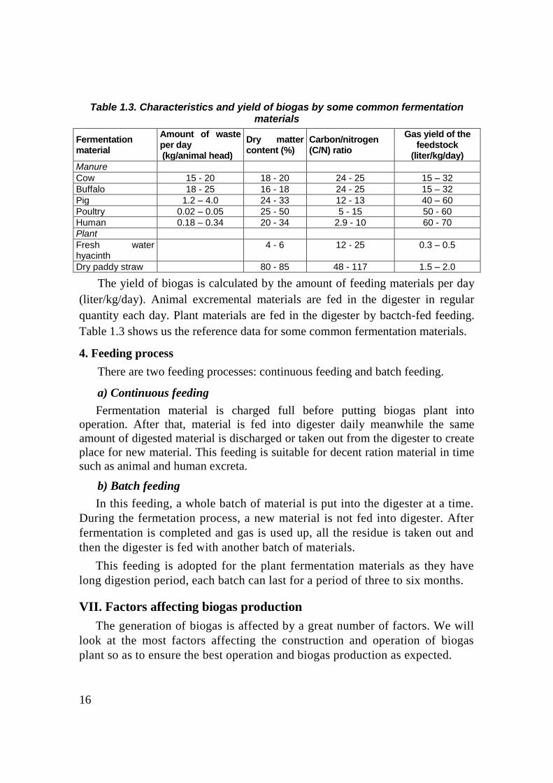
1. Operating cycle of fixed dome plant
The operating cycle of biogas plant consists of 2 stages:
- Stage1: Gas accumulation.
- Stage 2: Gas consumption.
Figure 2.9. Two limit stages of fixed dome plant
a) Stage 1: Gas accumulation
In the initial state of the cycle, the surface of the slurry in the digester and the
surface of the slurry contacting with the atmosphere at the inlet and outlet are equal

24
and are at the "zero level". At this time the biogas pressure in the digester is equal to
0 (p = 0).
Gas generated and accumulated in upper part of digester will create pressure on
the surface of slurry and push slurry up to compensation tank and inlet pipe. Since
the inlet pipe is small, slurry that is pushed out of digester will mainly be stored in
compensation tank. Therefore, we shall not refer to the volume of slurry rising in
inlet pipe.
The more gas is generated, the lower the surface of slurry and the higher the
surface of slurry in compensation tank. The difference between these two surfaces
represents gas pressure. The more gas is generated, the higher the pressure is.
Finally slurry in compensation tank rises to highest level called “overflow level”
and slurry in digester lowers to the lowest level. At this time, the gas pressure
reaches the maximum value (P = Pmax).
b) Stage 2: Gas consumption
When the valve is opened to release the gas for consumption, the slurry from the
compensating tank flows back into the digester tank. The surface of the slurry in the
compensating tank lowers meanwhile the surface of the slurry in the digester rises
up. The difference between these two surfaces and the gas pressure decrease
gradually.
Finally when the difference between the two surfaces of the slurry is equal to
zero, the biogas plant returns to the initial state of the operation cycle, P = 0 and the
gas outflow stops. The volume of gas (Vg), which can be extracted for consumption,
is equal to the volume of the slurry contained in the compensation tank.
It should be noted that there is still a certain gas volume stucked in the upper part
of digester from zero level upwards. This gas volume can not be used since there is
no pressure to push it out. This volume is called dead gas. The space that contain the
dead gas is called non-operation part of the digester
2. Conclusion
Based on above analysis, we could give some remarks as following:
a) The volume of slurry (from the lowest level down) is stable volume, which
is called digestion volume (Vd) of biogas plant. Only the volume of gas contained
in the part from the lowest level up to zero level can be used for consumption.
Therefore, this volume is called gas storage volume (Vg). The gas storage volume
above the zero level is the “dead volume” (Vo). The size of one biogas plant or
total volume of biogas digester is the total of Vd, Vg and Vo (V=Vd+Vg+ Vo).

25
b) Only one part of compensating tank from zero level up to overflow level
can regulate the gas pressure of digester, so it is the most appropriate if the
bottom of the compensating tank is at the "zero level", and Hg + Hc = Pmax. Hg
is distance from lowest level to zero level in digester and Hxa is distance from
overflow level to bottom of compensation tank (figure 2.10).
Figure 2.10. Appropriate structure of fixed dome biogas plant
III. Incorrect construction and operation
1. Incorrect operation
Figure 2.11. Two cases of incorrect operation of fixed dome plant
a) Feedstock is overfed
If too many materials are fed into digester, retention time is short and
digestion process of the feedstock is not completed. Therefore, animal dung will
overflow to compensation tank and cause pollution.
b) Feedstock is not fed enough
(a) Initial level of digestion slurry above the zero level
(b) Initial level of digestion slurry below the zero level

26
If the feedstock is not fed enough, total gas production is lower than
designed.
2. Incorrect construction
Figure 2.12. Bottom of compensation tank is defined incorrectly
For incorrect operation cases, it can be corrected by adjust the slurry volume.
However if bottom elevation of compensation tank was not located as designed,
the plan will not operate properly. The only solution is to destroy the plant and
reconstruct. Let’s consider the two cases of incorrect construction as below:
a) Bottom of compensation tank is above zero level
If overflow level is too high, it can cause problems as following:
- The difference between overflow level and the lowest level will exceed the
permissible Pmax
- If overflow level is higher the bottom of mixing tank and the lower end of
gas pipe, fresh slurry will rise up to mixing tank and scum will block the gas
pipe.
b) Bottom of compensation tank is below zero level
The real active volume of compensation tank (Vc’) is the part which is
above zero level. Thus the volume is smaller than gas volume generated and
contained in the digester: Vc’ < Vg. By the end of gas accumulation stage,
when gas volume in the digester is more than Vc’, slurry will overflow out of
compensation tank. When gas is released for consumption, only gas volume
that replaced by slurry volume Vc’ is pushed out of digester. Hence even
though the generated gas volume is Vg, only a part of the volume can be used.
From above analysis, we can see that for good operation of plant,
construction and operation must be done as design.
(a) Bottom of compensation tank is above zero level (b) Bottom of compensation tank is under zero level
27
IV. Prevention of gas leakage for fixed dome plant
To ensure the gas tight for fixed dome plant built of bricks, gas impermeable
materials like epoxy, paraffin, bitumen, ect. can be used.
Brick layer with porosity of 30% is neither water tight nor gas tight. It is just a
support for the mortar layer. It is the mortar layer that can prevent gas leakage. It is
necessary to do plastering the inner face of digester wall since it contacts directly
with the gas. The outer layer does not take this role and therefore it is not
necessary to do plastering the outer face.
To reach better penetration resistance, multiple thin mortar layers are
plastered instead of one thick layer. This can ensure water tight and gas tight
since it can prevent formation of capillary tubes.
For fixed dome biogas plant, seven steps of plastering inner side with gas
proof additives are also applied.
V. Scum breaks for fixed dome plant
1. Scum formulation
In the input materials there are always components which are lighter than
water like dung, straw, rice husk, sawdust or animal hair, ect. Since these
components float on slurry surface, they are not submerged under water and so
can not be digested. They become drier and adhere to each other forming a scum
layer. This layer become thicker and harder. The scum layer impedes the release
of gas. This scum also occupies a part of the operation volume of digester. The
thicker the scum layer is, the less the operation volume of digester is and the
efficiency of digester is less. For these two reasons, the gas production is much
less than it is at the beginning.
2. Scum eliminating measures
a) Removing scum
Measure to eliminate scum is to remove it periodically from digester. This is
a maintenance requirement for user. It is also an important requirement for
designer: an entrance must be designed for removing the scum. The entrance is
best located on digester or at the outlet.
b) Restricting scum formulation
Good operation can help to limit the formulation of scum:

28
- Reasonable dilution: This measure can be applied in designing (selecting
dilution ratio) and operation.
When applying reasonable dilution, slurry has high viscosity and therefore
light components could hardly rise to surface and form scum. On the contrary, if
the slurry is too dilute, light components can easily float and form scum.
- - Digestion slurry stirs:
Stirring slurry helps to move and break the scum and thus the scum
formulation slows down. Besides, it also increases gas production considerably
since it promotes the contact between undigested
slurry and bacteria. As the result reactions
happen more intensively.
Stirring is a measure in operation. However
in designing, it should be arranged so that
stirring can be done easily. Install a mixer to the
digester.
For fixed dome plant, mixer can be arranged
as shown in figure 2.13.
Mixer handle can be supported by a bearing
placed at the bottom. It is inserted in a pipe
which can both support the handle and keep gas
tight. The pipe must be placed deeply into the
slurry below minimum level to prevent the gas
from escaping.
In reality, this measure is not applied widely
because of complication.
Figure 2.13. Mixer used for
fixed dome biogas plants

29
Module 3
DESIGN SELECTION OF FIXED DOME BIOGAS PLANT
I. Sample design in sector standard of “10 TCN 102 – 2006”
1. Type of biogas plant
In this module, we go deep into the details of sample design in 10 TCN
102-2006 issued by Ministry of Agriculture and Rural Development. This is
deep fixed dome spherical biogas plant, type KT1 and Shallow fixed dome
spherical biogas plant, type KT2.
KT1 model was applied on the basis that good base structure, low underground water, deeped digging and narrow construction area.
KT2 model was applied on the basis that bad base structure, abundant
underground water, difficult deeped digging and wide construction space.
2. Range of design
Size design of biogas plant corresponds to domestic animal waste daily
charging are 50, 75, 100, 125, 150, 200, 250 and 300 kg/day, that is
corresponding to various parameters as sector, type of charging feedstock and
dilution ratio. These parameters are described in table 3.1
Table 3.1. Information and parametter for sample design
Information/parameter Unit Value
Type of charging material is domestic animal waste Pigs
Buffalo, Cattle
Gas yield : - Waste of pigs
- Waste of buffalo, cattle
liter/kg/day
60
30
Retention time:
- Cold winter area (Average temperature from 15 to 200C)
- Warm winter area (Average temperature above 200C)
day
40
30
Dilution ratio between water and domestic animal waste:
- Choice 1
- Choice 2
liter/kg
1
2
Gas storage coefficient 0,4

30
3. Some improvements of version 2 in comparison with version 1
Table 3.2. Comparison version 1 and version 2
Main change Version 1 Version 2
Size choice base Vd and Vd/Vg Amount of feedstock
Thickness of wall and bottom Approximately Structure = SAP 2000
Gas storage coefficient (liter/kg/day) 30; 50 36; 60
Dilution ratio (waste/water) 1/1 1/1 and 1/2
Retention time (day) 40, 50 30, 40
Heigh of digester neck ≈ 700 mm ≈ 400 mm
Overflow level Equal reference level Below reference level
( - 150 mm)
4. Design drawing
Each type is introduced in a drawing with the plan view (no filling ground
layer) and two basic sections.
The drawings consist of the following:
- Drawing 1 - Fixed dome biogas plant, type KT1
- Drawing 2 - Fixed dome biogas plant, type KT2
- Drawing 3 - Digester neck detail
- Drawing 4 - Digester cover detail
General dimension for all sizes of biogas plant is defined in design drawing.
Individual dimension of each size is represented by symbol and value
corresponding to regulations in table 3a, 3b, 3c, 3d, 4a, 4b, 4c, 4d. Each table
has 2 dilution ratios. First part is dilution ration 1:1 and the second is dilution
ratio 2:1(same amount of feedstock but the dimension of digester is bigger)
The main parameters, dimensions and materials corresponding to each
size are shown in an accompanying table.
a. For the biogas plant KT1
Table Scope of application Object of application
3a Cold winter area (Mean temperature from 15
to 200C) and pig waste.
Provinces in the North
(including Thua Thien
Hue province) 3b Cold winter area (Mean temperature from 15
to 200C) and buffalo or cattle waste.
3c No cold winter area (Mean temperature
above 200C) and pig waste.
Provinces in the South
3d No cold winter area (Mean temperature
above 200C) and buffalo or cattle waste.
31
b. For the biogas plant KT2
Table Scope of application Object of application
4a Cold winter area (Mean temperature from 15
to 200C) and pig waste.
Provinces in the North
(including Thua Thien
Hue province) 4b Cold winter area (Mean temperature from 15
to 200C) and buffalo or cattle waste.
4c No cold winter area (Mean temperature
above 200C) and pig waste.
Provinces in the South
4d No cold winter area (Mean temperature
above 200C) and buffalo or cattle waste.
5. Drawing reading
Fixed dome biogas plant includes 3 tanks. According to sequence, from left
to right is mixing tank, digester tank and compensation tank. The connection
among tanks is inlet and outlet pipes.
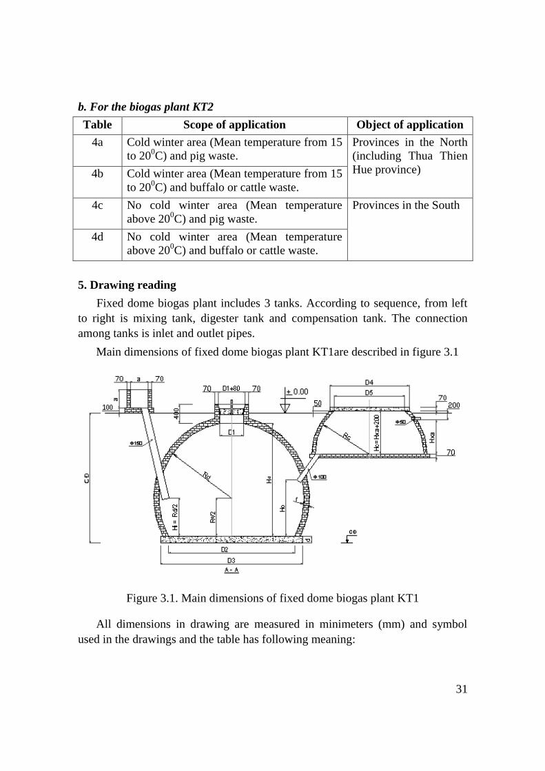
Main dimensions of fixed dome biogas plant KT1are described in figure 3.1
Figure 3.1. Main dimensions of fixed dome biogas plant KT1
All dimensions in drawing are measured in minimeters (mm) and symbol
used in the drawings and the table has following meaning:

32
Values represented by the symbols Symbol Values represented by the symbols Symbol
Radius of digester tank Rd Diameter of digester wall foot D2
Radius of compensating tank Rc Diameter of digester tank bottom D3
Height of digester tank special zone
Hd Diameter of compensation tank cover D4
Height from bottom to inlet pipe Hi Diameter of compensation tank orifice D5
Height from bottom to outlet pipe Ho Depth of digester tank CĐ
Height of overflow level Hxa Dimension of mixing tank a
Height of compensation tank special zone
Hc Thickness of digester bottom d
Diameter of digester tank orifice D1 Thickness of digester tank wall t
Main dimensions of fixed dome biogas plant KT2 are described in figure 3.2
Figure 3.2. Main dimensions of fixed dome biogas plant KT2
All dimensions in drawing are measured in mimimeters (mm), the main
parameters, dimensions and materials corresponding with each size are shown in
following table:
Values represented by the symbols Symbol Values represented by the symbols Symbol
Radius of digester tank Rd Diameter of digester wall foot D2
Radius of compensating tank Rc Diameter of digester tank bottom D3
Height of digester tank special zone
Hd Diameter of compensation tank cover D4
Height from bottom to inlet pipe Hi Diameter of compensation tank orifice D5
Height from bottom to outlet pipe Ho Depth of digester tank CĐ
Height of overflow level Hxa Dimension of mixing tank a
Height of compensation tank special zone
Hc Thickness of digester bottom d
Diameter of digester tank orifice D1 Thickness of digester tank wall t

33
II. Calculation method
In this module, we only considered the simple fixed dome biogas plants.
Family scale biogas plants are simple ones, operating by continuous feeding
regime with feedstock being animal waste and dilution ratio.
1. Selection of initial parameters
a) Daily supply of feedstock, Md (kg/day)
Depending on the target of designer.
b) Dilution ratio, N (l/kg)
For pig and cattle waste, when designing usually a dilution ratio of 1or 2 liter
of water per 1 kg of waste (1l/kg) is selected
c) Gas yield of the feedstock, Y (l/kg/day)
Selected according to table 1.3 in Module 1, part II.
d) Retention time, RT (day)
Selected according to table 1.4 in Module 1, part II.
e) Gas storage coefficient, K
Selected according to longest the gas consumption demand
For example:
For daily cooking and lighting: It is needed only to store gas during the night
time (12 hours), so K is assumed to be = 12/24 = 0.5.
If gas is used only for operating the generator or lighting during the night
time, the longest gas storing duration is 20 hours/day, K = 20/24 = 0.8.
2. Calculation on specific parameters of biogas plant
a) Daily feedstock filling, Sd (l/day)
The daily supply of slurry is equal to the daily amount of feedstock plus the
amount of diluting water. As the density of the waste approximately equal to 1,
its volume can be considered as equal to its mass.
Therefore: Sd = (1+N) x Md
With the dilution ration 1:1, so N=1
With the dilution ration 2:1, so N=2
b) Digestion volume, Vd (m3)
Vd = Sd × RT / 1000

34
In the above equation is a division by 1,000 as Sd is in liters while Vd is in
m3.
c) Capacity of biogas plant, (m3/day)
G = Md x Y / 1000
d) Gas storage volume, Vg (m3)
The gas storage volume is calculated based on the capacity of biogas plant
and the gas storage coefficient (K).
The gas storage volume (m3):
Vg = K x G
e) Compensating tank volume, Vc (m3)
The effective volume of the gasholder component or compensating must be
equal to the volume of gas to be stored.
Vc = Vg
III. Selection type, size of biogas plant and design the dimensions of
auxiliary components
Specific parameters and detail dimensions of biogas plant are chosen based
on sample design. Firstly, we must choose type and size of biogas plant.
1. Selection type of biogas plant
The selection of biogas plant type must be based on the following factors:
- Type and quantity of feedstock to be used.
- Geographic, hydrographic, climate, etc.
2. Selection of biogas plant size
The selection of biogas plant size must be based on the following factors:
- Type and quantity of feedstock to be fed;
- Climatic conditions in the locality;
- The dilution ratio
- The gas consumption demand.
Implementation steps are described as follow:
- Identify main feed waste and amount of daily feeding waste;
35
- Refer to table (or technical drawing issued by Biogas Project Division)
related to parameters as biogas plant type, animal waste type, applied region and
dilution ratio for determining the suitable biogas plant size
The sample design has only two feedstock types. That is buffalo waste and
pig waste. If in case, the buffalo waste is equal pig waste, we chose biogas plant
size applied for pig waste. And in case, the buffalo waste is bigger than pig
waste, we chose the biogas plant size applied for buffalo and vice versa
The dilution ration (1kg animal waste for 1-2 litters of water) is chosen
according to the dilution water using of each household.
Daily animal waste is estimated based on table 2.2 in module 2, part II.
However, daily collected feedstock to fill the digester is calculated depending on
breeding method. If the animal is kept in stable and stable foundation is laid by
brick or poured concrete so filling feedstock is equal domestic animal waste
amount. If daytime grazing, put animal into custody at night only so collected
animal waste is only equal from 40 to 50% of domestic animal waste amount.
For waste treatment need, when calculating daily animal waste, we should
consider to maximum animal waste and breeding development trend for the
biogas plant. Hence, when fact waste amount is not equal waste amount in design
then we should choose the size of biogas plant corresponding with larger supply
of waste.
+ Example 1: A household in Bac Ninh has 12 porkers. The weight of each
porker is 70kg. Stable foundation is laid by brick. Dilution ratio is 1 kg animal
waste for 2 litters of water. The household wants to construct a biogas plant of
KT2 model. Pig waste on percent of pig weight is 5%. We calculate the
following parameters:
Daily feedstock filling in the digester is:
70 × 5% × 12 = 42 kg/day
The daily supply of waste is 42kg/day. But in the table 3a has not any biogas
size corresponding to this daily supply of waste. So we chose size of biogas plant
corresponding to larger supply of waste. Refer to table 3a with the dilution ratio
2:1, we chose biogas plant with capacity of 7.6 m3
+ Example 2: A household in Binh Dinh often has 2 sows with 200kg/sow
weight and 10 poekers (piggy is retained for breeding). The sow delivers average
10 piggies for each time. The weight of each porker is 70kg. Brick laid pigsty

36
have urine and dung collected drain for filling in the digester. The household
wants to construct a biogas plant of KT2 model, using the dilution ratio is 1:1
and waste amount based on pig’s quantity percent is 5%. We calculate the
following parameters
Daily feedstock filling in the digester is:
From 2 sows: 200 × 5% × 2 = 20 kg/day
From 10 piggies: 20 × 5% × 10 = 10 kg/day
From 10 porkers: 70 × 5% × 15 = 35 kg/day
Total: 65 kg/day
The daily supply of waste is 65kg/day. But in the table 4c has not any biogas
size corresponding to this daily supply of waste. So we chose size of biogas plant
corresponding to larger supply of waste. Refer to table 4c with the dilution ratio
1:1, we chose biogas plant with capacity of 7.6 m3
3. Calculating the dimensions of auxiliary components
a) Mixing tank
The feedstock is mixed with water to form
uniform slurry in the mixing tank. The indigestible
materials such as sand, stone, gravel, wood, etc. are
removed here.
The opening of the inlet pipe should be a few cm
higher than the bottom of the mixing tank so that the
settled sediment does not enter the digest:er and stay
on the bottom of the mixing tank, from where it can
be easily removed.
The bottom of the mixing tank must be higher
than the overflow level to prevent the newly fed
slurry (fresh dung) from spilling onto the mixing
tank causing unhygienic conditions.
If the dung is flowed by gravity from the sty to the mixing tank, the bottom
of the mixing tank must be higher than the floor of the stable.
It is recommended to make a cover for the opening of the inlet pipe and to
use a steel hook to move it. When mixing the dung with water the cover closes
Figure 3.3.: Mixing tank

37
the inlet pipe. Then the cover is removed to let the slurry to flow into the
digester.
b) Inlet pipe and outlet pipe
The inlet and outlet pipes connected to the digester must be straight, with no
angular places to avoid the risk of clogging. The inlet pipe should be of the size
from 150 to 200 mm. The outlet pipe may be smaller, with the size from 90 to
100 mm. At present, PVC pipes are recommended for easy installation.
Lower of outlet pipe is installed lower than lowest level by at least 10 cm for
pressure limitation and digester breaking prevention.
Figure 3.4. The inlet and outlet pipes must be straight
c) Outlet gas pipe
In order to prevent the gas pipe from blockage due to scum, the lower outlet
of gas pipe must be located higher than overflow level.

38
Table 3a. Parameters, dimension and material of fixed dome biogas plant, KT1 type For cold winter area (mean temperature from 15 to 200C) and pig waste (dung and urine)
Parameters Unit Dilution ratio 1: 1 Dilution ratio 2: 1
Size m3 6,0 9,0 12,0 15,0 18,1 24,1 30,2 35,0 8,1 12,1 16,3 20,3 24,4 32,5 40,6 48,6
Daily supply of waste kg/day 50 75 100 125 150 200 250 300 50 75 100 125 150 200 250 300
Dilution water amount litter/day 50 75 100 125 150 200 250 300 100 150 200 250 300 400 500 600
Digestion volume (Vd) m3 4,0 6,0 8,0 10,0 12,0 16,0 20,0 24,0 6,0 9,0 12,0 15,0 18,0 24,0 30,0 36,0
Gas storage volume (Vg) m3 1,2 1,8 2,4 3,0 3,6 4,8 6,0 7,2 1,2 1,8 2,4 3,0 3,6 4,8 6,0 7,2
Total construction volume (Vtg) m3 7,5 11,2 14,9 18,6 22,4 29,8 37,1 43,6 9,6 14,4 19,2 23,9 28,7 38,1 47,6 56,9
Maximum pressure (Pmax) cmH2O 88 100 111 119 125 138 149 150 84 96 105 113 120 132 142 150
Radius of digester (Rd) mm 1195 1367 1505 1621 1724 1898 2044 2148 1319 1509 1663 1792 1904 2096 2257 2396
Radius of compensation tank (Rc) mm 893 1024 1128 1217 1296 1425 1537 1712 894 1027 1130 1218 1296 1426 1539 1644
Height of digester tank special zone (Hd) mm 1763 2026 2235 2410 2557 2821 3043 3199 1952 2241 2466 2661 2830 3120 3364 3574
Height from bottom to inlet pipe (Hi) mm 597 684 753 810 862 949 1022 1074 659 755 832 896 952 1048 1128 1198
Height from bottom to outlet pipe (Ho) mm 852 991 1100 1194 1273 1410 1526 1670 1080 1252 1383 1498 1599 1769 1914 2046
Height of overflow level (Hxa) mm 547 623 685 733 775 854 918 852 545 619 681 732 774 852 914 956
Height of compensation tank (Hc) mm 747 823 885 933 975 1054 1118 1052 745 819 881 932 974 1052 1114 1156
Diameter of digester tank orifice (D1) mm 520 520 520 520 620 620 620 620 520 520 620 620 620 620 620 620
Diameter of digester wall foot (D2) mm 2069 2368 2607 2807 2985 3287 3541 3720 2284 2614 2881 3103 3297 3630 3909 4150
Diameter of compensation tank bottom (D3) mm 2329 2741 2981 3181 3360 3661 3915 4095 2545 2875 3255 3478 3671 4004 4284 4525
Diameter of compensation tank orifice (D4) mm 1255 1483 1653 1813 1953 2161 2347 2916 1264 1499 1668 1818 1955 2168 2361 2569
Diameter of compensation tank (D5) mm 977 1221 1397 1563 1707 1919 2108 2700 989 1239 1414 1568 1709 1926 2123 2336
Depth of digester tank (CĐ) mm 2083 2366 2575 2780 2927 3191 3413 3619 2292 2581 2836 3031 3200 3490 3784 3994
Dimension of mixing tank (a) mm 400 400 400 400 500 500 500 500 400 400 500 500 500 500 500 500
Thickness of digester bottom (d) mm 100 120 120 150 150 150 150 200 120 120 150 150 150 150 200 200
Thickness of digester wall (t) mm 70 120 120 120 120 120 120 120 70 70 120 120 120 120 120 120
Tablet brick tablet 890 1590 1900 2180 2450 2940 3390 3760 980 1250 2180 2510 2820 3390 3910 4390
Cement PCB 30 kg 560 760 910 1120 1260 1510 1730 2170 660 850 1120 1290 1440 1720 2220 2490
Sand m3 1,2 1,6 1,9 2,3 2,6 3,1 3,6 4,3 1,4 1,8 2,3 2,7 3,0 3,5 4,4 4,9
Crushed stone/gravel m3 0,5 0,8 0,9 1,3 1,4 1,7 1,9 2,8 0,7 0,9 1,3 1,5 1,6 1,9 2,8 3,2
Steel with diameter of 6mm kg 7 11 14 15 19 21 26 41 7 11 14 15 19 21 27 33

39
Table 3b. Parameters, dimension and material of fixed dome biogas plant, KT1 type For cold winter area (mean temperature from 15 to 200C) and buffalo and cow waste (dung and urine)
Parameters Unit Dilution ratio 1: 1 Dilution ratio 2: 1
Size m3 5,3 7,9 10,5 13,2 15,9 21,2 26,5 31,8 7,3 11,0 14,7 18,4 22,1 29,4 36,8 44,2
Daily supply of waste kg/day 50 75 100 125 150 200 250 300 50 75 100 125 150 200 250 300
Dilution water amount litter/day 50 75 100 125 150 200 250 300 100 150 200 250 300 400 500 600
Digestion volume (Vd) m3 4,0 6,0 8,0 10,0 12,0 16,0 20,0 24,0 6,0 9,0 12,0 15,0 18,0 24,0 30,0 36,0
Gas storage volume (Vg) m3 0,7 1,1 1,4 1,8 2,2 2,9 3,6 4,3 0,7 1,1 1,4 1,8 2,2 2,9 3,6 4,3
Total construction volume (Vtg) m3 6,2 9,3 12,4 15,4 18,5 24,7 30,8 36,9 8,3 12,4 16,6 20,6 24,8 32,9 41,1 49,3
Maximum pressure (Pmax) cmH2O 71 81 88 95 100 110 119 126 68 77 84 91 96 106 114 121
Radius of digester (Rd) mm 1144 1309 1440 1552 1650 1816 1956 2079 1276 1460 1609 1733 1842 2027 2184 2320
Radius of compensation tank (Rc) mm 752 863 953 1025 1093 1202 1296 1377 754 865 953 1029 1092 1204 1297 1380
Height of digester tank special zone (Hd) mm 1685 1937 2136 2306 2445 2698 2910 3096 1887 2167 2384 2571 2737 3016 3253 3460
Height from bottom to inlet pipe (Hi) mm 572 654 720 776 825 908 978 1040 638 730 805 866 921 1013 1092 1160
Height from bottom to outlet pipe (Ho) mm 949 1101 1224 1324 1412 1563 1692 1803 1180 1367 1509 1636 1742 1929 2085 2222
Height of overflow level (Hxa) mm 464 528 574 622 653 722 774 824 461 523 575 614 656 717 772 819
Height of compensation tank (Hc) mm 664 728 774 822 853 922 974 1024 661 723 775 814 856 917 972 1019
Diameter of digester tank orifice (D1) mm 520 520 520 520 620 620 620 620 520 520 620 620 620 620 620 620
Diameter of digester wall foot (D2) mm 1981 2267 2494 2688 2857 3146 3388 3601 2210 2529 2787 3001 3190 3511 3782 4019
Diameter of compensation tank bottom (D3) mm 2241 2527 2754 2948 3231 3520 3763 3976 2471 2790 3048 3262 3451 3885 4157 4394
Diameter of compensation tank orifice (D4) mm 1011 1207 1378 1487 1622 1792 1954 2084 1022 1228 1376 1518 1611 1811 1962 2103
Diameter of compensation tank (D5) mm 709 927 1112 1225 1368 1542 1709 1841 723 952 1109 1260 1355 1562 1717 1861
Depth of digester tank (CĐ) mm 2005 2277 2476 2646 2815 3068 3280 3466 2207 2507 2754 2941 3107 3386 3673 3880
Dimension of mixing tank (a) mm 400 400 400 400 500 500 500 500 400 400 500 500 500 500 500 500
Thickness of digester bottom (d) mm 100 120 120 120 150 150 150 150 100 120 150 150 150 150 200 200
Thickness of digester wall (t) mm 70 70 70 70 120 120 120 120 70 70 70 70 70 120 120 120
Tablet brick tablet 750 950 1130 1290 2120 2540 2930 3300 850 1090 1290 1480 1660 3000 3460 3900
Cement PCB 30 kg 480 650 770 880 1090 1300 1490 1670 550 750 970 1120 1250 1520 1970 2210
Sand m3 1,1 1,4 1,7 1,9 2,3 2,7 3,1 3,4 1,2 1,6 2,0 2,3 2,6 3,1 3,9 4,4
Crushed stone/gravel m3 0,5 0,7 0,8 0,9 1,3 1,5 1,7 1,9 0,5 0,8 1,1 1,3 1,4 1,8 2,6 2,9
Steel with diameter of 6mm kg 4 7 10 11 12 15 19 21 4 7 10 11 11 15 19 21

40
Table 3c. Parameters, dimension and material of fixed dome biogas plant, KT1 type
For no cold winter area (mean temperature above 200C) and pig waste (dung and unire)
Parameters Unit Dilution ratio 1: 1 Dilution ratio 2: 1
Size m3 5,0 7,5 9,9 12,4 14,9 19,9 24,4 28,0 6,5 9,8 13,1 16,4 19,7 26,2 32,8 38,5
Daily supply of waste kg/day 50 75 100 125 150 200 250 300 50 75 100 125 150 200 250 300
Dilution water amount litter/day 50 75 100 125 150 200 250 300 100 150 200 250 300 400 500 600
Digestion volume (Vd) m3 3,0 4,5 6,0 7,5 9,0 12,0 15,0 18,0 4,5 6,8 9,0 11,3 13,5 18,0 22,5 27,0
Gas storage volume (Vg) m3 1,2 1,8 2,4 3,0 3,6 4,8 6,0 7,2 1,2 1,8 2,4 3,0 3,6 4,8 6,0 7,2
Total construction volume (Vtg) m3 6,5 9,7 12,8 16,0 19,2 25,5 31,5 36,9 8,1 12,0 16,0 20,0 24,0 31,9 39,8 47,0
Maximum pressure (Pmax) cmH2O 91 104 114 123 130 143 150 150 87 99 109 117 124 136 147 150
Radius of digester (Rd) mm 1121 1283 1412 1521 1616 1780 1905 1994 1228 1406 1547 1668 1773 1951 2102 2216
Radius of compensation tank (Rc) mm 893 1023 1127 1215 1292 1426 1568 1791 894 1025 1130 1219 1295 1427 1537 1688
Height of digester tank special zone (Hd) mm 1650 1897 2093 2259 2403 2642 2833 2967 1814 2084 2298 2473 2632 2901 3129 3302
Height from bottom to inlet pipe (Hi) mm 560 641 706 760 808 890 953 997 614 703 773 834 886 975 1051 1108
Height from bottom to outlet pipe (Ho) mm 711 829 922 1001 1071 1187 1303 1437 915 1062 1180 1276 1362 1509 1633 1773
Height of overflow level (Hxa) mm 548 626 686 737 781 854 865 761 546 622 680 730 776 852 917 885
Height of compensation tank (Hc) mm 748 826 886 937 981 1054 1065 961 746 822 880 930 976 1052 1117 1085
Diameter of digester tank orifice (D1) mm 520 520 520 520 520 620 620 620 520 520 520 620 620 620 620 620
Diameter of digester wall foot (D2) mm 1941 2222 2445 2634 2799 3082 3300 3454 2127 2435 2679 2889 3070 3379 3640 3838
Diameter of compensation tank bottom (D3) mm 2201 2595 2819 3008 3173 3457 3675 3828 2387 2695 3053 3263 3444 3753 4015 4213
Diameter of compensation tank orifice (D4) mm 1253 1472 1649 1798 1931 2162 2528 3227 1262 1487 1672 1823 1948 2169 2353 2807
Diameter of compensation tank (D5) mm 976 1208 1393 1546 1683 1920 2300 3022 987 1225 1418 1574 1701 1928 2114 2587
Depth of digester tank (CĐ) mm 1970 2217 2433 2599 2773 3012 3203 3337 2134 2424 2638 2843 3002 3271 3549 3722
Dimension of mixing tank (a) mm 400 400 400 400 400 500 500 500 400 400 400 500 500 500 500 500
Thickness of digester bottom (d) mm 100 100 120 120 150 150 150 150 100 120 120 150 150 150 200 200
Thickness of digester wall (t) mm 70 120 120 120 120 120 120 120 70 70 120 120 120 120 120 120
Tablet brick tablet 830 1460 1740 2000 2250 2690 3080 3420 910 1160 1970 2270 2540 3060 3520 3920
Cement PCB 30 kg 520 670 840 970 1160 1390 1600 1830 580 780 940 1170 1310 1560 2000 2250
Sand m3 1,1 1,5 1,8 2,1 2,4 2,9 3,3 3,8 1,3 1,7 2,0 2,4 2,7 3,2 4,0 4,5
Crushed stone/gravel m3 0,5 0,6 0,8 1,0 1,3 1,5 1,8 2,1 0,5 0,8 1,0 1,3 1,5 1,7 2,5 2,9
Steel with diameter of 6mm kg 7 10 14 15 19 21 32 50 7 11 14 16 19 21 27 40

41
Table 3d. Parameters, dimension and material of fixed dome biogas plant, KT1 type For no cold winter area (mean temperature above 200C) and buffalo and cow waste (dung and unire)
Parameters Unit Dilution ratio 1: 1 Dilution ratio 2: 1
Size m3 4,2 6,4 8,5 10,6 12,7 17,0 21,3 25,5 5,8 8,7 11,6 14,5 17,4 23,2 29,1 34,9
Daily supply of waste kg/day 50 75 100 125 150 200 250 300 50 75 100 125 150 200 250 300
Dilution water amount litter/day 50 75 100 125 150 200 250 300 100 150 200 250 300 400 500 600
Digestion volume (Vd) m3 3,0 4,5 6,0 7,5 9,0 12,0 15,0 18,0 4,5 6,8 9,0 11,3 13,5 18,0 22,5 27,0
Gas storage volume (Vg) m3 0,7 1,1 1,4 1,8 2,2 2,9 3,6 4,3 0,7 1,1 1,4 1,8 2,2 2,9 3,6 4,3
Total construction volume (Vtg) m3 5,2 7,7 10,3 12,8 15,3 20,5 25,5 30,6 6,8 10,1 13,4 16,8 20,1 26,7 33,4 40,0
Maximum pressure (Pmax) cmH2O 73 83 91 98 104 114 123 130 70 79 87 93 99 109 117 124
Radius of digester (Rd) mm 1063 1217 1339 1442 1532 1688 1819 1933 1179 1350 1486 1602 1702 1873 2019 2145
Radius of compensation tank (Rc) mm 753 862 951 1026 1091 1202 1295 1376 754 864 951 1027 1093 1204 1295 1379
Height of digester tank special zone (Hd) mm 1562 1797 1983 2139 2276 2503 2701 2874 1740 1999 2206 2373 2524 2784 3004 3194
Height from bottom to inlet pipe (Hi) mm 531 608 669 721 766 844 909 966 590 675 743 801 851 937 1009 1072
Height from bottom to outlet pipe (Ho) mm 806 936 1041 1130 1206 1335 1445 1542 1014 1175 1303 1408 1504 1665 1799 1920
Height of overflow level (Hxa) mm 462 529 579 620 658 720 777 824 460 525 578 617 652 717 776 821
Height of compensation tank (Hc) mm 662 729 779 820 858 920 977 1024 660 725 778 817 852 917 976 1021
Diameter of digester tank orifice (D1) mm 520 520 520 520 520 620 620 620 520 520 520 620 620 620 620 620
Diameter of digester wall foot (D2) mm 1840 2107 2319 2497 2654 2924 3150 3347 2042 2338 2574 2775 2947 3244 3496 3715
Diameter of compensation tank bottom (D3) mm 2100 2368 2579 2758 3028 3298 3524 3722 2302 2598 2834 3035 3208 3619 3871 4089
Diameter of compensation tank orifice (D4) mm 1020 1202 1359 1494 1603 1796 1947 2082 1027 1218 1364 1504 1624 1810 1950 2096
Diameter of compensation tank (D5) mm 721 921 1090 1233 1346 1547 1700 1839 730 940 1096 1244 1370 1562 1703 1853
Depth of digester tank (CĐ) mm 1882 2117 2323 2479 2616 2873 3071 3244 2060 2339 2546 2743 2894 3154 3374 3614
Dimension of mixing tank (a) mm 400 400 400 400 400 500 500 500 400 400 400 500 500 500 500 500
Thickness of digester bottom (d) mm 100 100 120 120 120 150 150 150 100 120 120 150 150 150 150 200
Thickness of digester wall (t) mm 70 70 70 70 120 120 120 120 70 70 70 70 70 120 120 120
Tablet brick tablet 700 880 1040 1190 1910 2290 2640 2960 780 990 1170 1340 1500 2660 3070 3450
Cement PCB 30 kg 440 560 700 800 910 1180 1350 1520 500 670 800 1000 1120 1360 1560 1960
Sand m3 1,0 1,2 1,5 1,7 1,9 2,4 2,8 3,1 1,1 1,5 1,7 2,1 2,3 2,8 3,2 3,9
Crushed stone/gravel m3 0,4 0,5 0,7 0,8 0,9 1,3 1,5 1,7 0,5 0,7 0,8 1,1 1,3 1,6 1,8 2,6
Steel with diameter of 6mm kg 4 7 10 11 11 15 19 21 4 7 10 11 12 15 19 21

42
Table 4a. Parameters, dimension and material of fixed dome biogas plant, KT2 type For cold winter area (mean temperature from 15 to 200C) and pig waste (dung and urine)
Parameters Unit Dilution ratio 1: 1 Dilution ratio 2: 1
Size m3 6,2 9,2 12,2 15,2 18,4 24,5 30,6 36,6 8,2 12,4 16,5 20,5 24,7 33,0 41,0 49,2
Daily supply of waste kg/day 50 75 100 125 150 200 250 300 50 75 100 125 150 200 250 300
Dilution water amount litter/day 50 75 100 125 150 200 250 300 100 150 200 250 300 400 500 600
Digestion volume (Vd) m3 4,0 6,0 8,0 10,0 12,0 16,0 20,0 24,0 6,0 9,0 12,0 15,0 18,0 24,0 30,0 36,0
Gas storage volume (Vg) m3 1,2 1,8 2,4 3,0 3,6 4,8 6,0 7,2 1,2 1,8 2,4 3,0 3,6 4,8 6,0 7,2
Total construction volume (Vtg) m3 7,7 11,5 15,2 18,9 22,7 30,2 37,7 45,0 9,8 14,6 19,5 24,2 29,1 38,7 48,1 57,6
Maximum pressure (Pmax) cmH2O 81 92 100 108 114 125 135 142 78 89 97 103 110 121 129 137
Radius of digester (Rd) mm 1434 1640 1800 1938 2063 2270 2446 2595 1579 1808 1992 2140 2277 2506 2695 2864
Radius of compensation tank (Rc) mm 896 1030 1147 1238 1314 1450 1562 1668 900 1033 1139 1240 1312 1446 1569 1669
Height of digester tank special zone (Hd) mm 1411 1619 1781 1921 2040 2248 2426 2577 1558 1789 1967 2118 2256 2487 2677 2847
Height from bottom to inlet pipe (Hi) mm 333 383 425 458 484 534 574 613 423 485 532 577 611 673 728 774
Height from bottom to outlet pipe (Ho) mm 567 665 749 815 869 967 1049 1125 747 870 964 1055 1123 1246 1356 1448
Height of overflow level (Hxa) mm 542 611 651 697 743 812 875 915 534 607 664 694 746 817 863 914
Height of compensation tank (Hc) mm 742 811 851 897 943 1012 1075 1115 734 807 864 894 946 1017 1063 1114
Diameter of digester tank orifice (D1) mm 520 520 520 520 620 620 620 620 520 520 620 620 620 620 620 620
Diameter of digester wall foot (D2) mm 2869 3280 3599 3877 4126 4539 4891 5190 3159 3616 3983 4280 4554 5012 5390 5728
Diameter of compensation tank bottom (D3) mm 3009 3420 3839 4117 4366 4779 5131 5430 3299 3756 4123 4520 4794 5252 5630 5968
Diameter of compensation tank orifice (D4) mm 1277 1527 1779 1942 2065 2308 2496 2707 1307 1544 1730 1954 2056 2289 2536 2713
Diameter of compensation tank (D5) mm 1004 1271 1538 1704 1829 2077 2266 2482 1040 1290 1483 1717 1820 2056 2309 2488
Depth of digester tank (CĐ) mm 1751 1989 2151 2291 2410 2668 2846 2997 1898 2159 2337 2538 2676 2907 3097 3267
Dimension of mixing tank (a) mm 400 400 400 400 500 500 500 500 400 400 500 500 500 500 500 500
Thickness of digester bottom (d) mm 120 150 150 150 150 200 200 200 120 150 150 200 200 200 200 200
Thickness of digester wall (t) mm 70 70 120 120 120 120 120 120 70 70 70 120 120 120 120 120
Tablet brick tablet 1080 1380 2440 2820 3200 3840 4430 4970 1220 1560 1900 3310 3720 4480 5150 5800
Cement PCB 30 kg 700 1000 1220 1410 1590 2200 2530 2840 810 1150 1390 1900 2130 2550 2940 3300
Sand m3 1,4 2,0 2,4 2,7 3,1 4,1 4,7 5,3 1,6 2,2 2,7 3,5 4,0 4,7 5,4 6,1
Crushed stone/gravel m3 0,9 1,4 1,8 2,0 2,3 3,5 4,0 4,5 1,1 1,7 2,0 3,1 3,5 4,2 4,8 5,3
Steel with diameter of 6mm kg 7 10 14 16 19 22 27 33 7 10 12 16 19 22 27 33

43
Table 4b. Parameters, dimension and material of fixed dome biogas plant, KT2 type For cold winter area (mean temperature from 15 to 200C) and buffalo and cow waste (dung and urine)
Parameters Unit Dilution ratio 1: 1 Dilution ratio 2: 1
Size m3 5,4 8,0 10,7 13,3 16,0 21,4 26,7 32,0 7,4 11,2 14,9 18,6 22,3 29,7 37,1 44,5
Daily supply of waste kg/day 50 75 100 125 150 200 250 300 50 75 100 125 150 200 250 300
Dilution water amount litter/day 50 75 100 125 150 200 250 300 100 150 200 250 300 400 500 600
Digestion volume (Vd) m3 4,0 6,0 8,0 10,0 12,0 16,0 20,0 24,0 6,0 9,0 12,0 15,0 18,0 24,0 30,0 36,0
Gas storage volume (Vg) m3 0,7 1,1 1,4 1,8 2,2 2,9 3,6 4,3 0,7 1,1 1,4 1,8 2,2 2,9 3,6 4,3
Total construction volume (Vtg) m3 6,4 9,4 12,5 15,6 18,8 25,0 31,1 37,2 8,4 12,6 16,7 20,9 25,0 33,3 41,4 49,7
Maximum pressure (Pmax) cmH2O 66 74 81 87 92 102 108 115 63 73 78 85 89 98 105 111
Radius of digester (Rd) mm 1371 1564 1722 1854 1971 2171 2336 2482 1525 1748 1921 2072 2199 2421 2606 2770
Radius of compensation tank (Rc) mm 752 873 962 1040 1108 1218 1319 1403 759 865 965 1036 1109 1219 1320 1402
Height of digester tank special zone (Hd) mm 1346 1543 1702 1836 1947 2149 2316 2463 1503 1729 1896 2049 2177 2401 2588 2753
Height from bottom to inlet pipe (Hi) mm 376 435 479 516 548 602 650 691 470 536 592 636 679 746 806 855
Height from bottom to outlet pipe (Ho) mm 653 770 857 933 996 1103 1201 1283 840 971 1085 1172 1258 1392 1511 1611
Height of overflow level (Hxa) mm 465 509 557 594 627 693 734 778 451 523 552 602 626 692 733 780
Height of compensation tank (Hc) mm 665 709 757 794 827 893 934 978 651 723 752 802 826 892 933 980
Diameter of digester tank orifice (D1) mm 520 520 520 520 620 620 620 620 520 520 620 620 620 620 620 620
Diameter of digester wall foot (D2) mm 2743 3129 3444 3708 3943 4343 4673 4965 3050 3497 3843 4144 4397 4843 5212 5540
Diameter of compensation tank bottom (D3) mm 2883 3269 3584 3848 4083 4583 4913 5205 3190 3637 3983 4284 4537 4983 5452 5780
Diameter of compensation tank orifice (D4) mm 1006 1284 1443 1591 1719 1895 2096 2245 1068 1226 1462 1562 1723 1901 2100 2237
Diameter of compensation tank (D5) mm 702 1019 1188 1343 1476 1655 1862 2014 782 950 1209 1310 1480 1661 1867 2005
Depth of digester tank (CĐ) mm 1686 1883 2072 2206 2317 2569 2736 2883 1843 2099 2266 2419 2597 2821 3008 3173
Dimension of mixing tank (a) mm 400 400 400 400 500 500 500 500 400 400 500 500 500 500 500 500
Thickness of digester bottom (d) mm 120 120 150 150 150 200 200 200 120 150 150 150 200 200 200 200
Thickness of digester wall (t) mm 70 70 70 70 70 120 120 120 70 70 70 70 70 70 120 120
Tablet brick tablet 930 1180 1410 1610 1840 3370 3870 4360 1070 1380 1660 1910 2130 2560 4630 5210
Cement PCB 30 kg 610 780 1040 1190 1350 1930 2220 2490 720 1030 1240 1430 1870 2240 2640 2960
Sand m3 1,3 1,6 2,0 2,3 2,6 3,6 4,1 4,6 1,5 2,0 2,4 2,8 3,5 4,2 4,9 5,4
Crushed stone/gravel m3 0,8 1,0 1,5 1,7 2,0 3,2 3,6 4,1 1,0 1,5 1,8 2,1 3,1 3,7 4,4 4,9
Steel with diameter of 6mm kg 4 7 8 11 12 15 20 21 4 6 10 10 12 15 20 21

44
Table 4c. Parameters, dimension and material of fixed dome biogas plant, KT2 type
For no cold winter area (mean temperature above 200C) and pig waste (dung and unire)
Parameters Unit Dilution ratio 1: 1 Dilution ratio 2: 1
Size m3 5,1 7,6 10,1 12,7 15,1 20,3 25,4 30,3 6,6 9,9 13,3 16,6 19,9 26,5 33,1 39,8
Daily supply of waste kg/day 50 75 100 125 150 200 250 300 50 75 100 125 150 200 250 300
Dilution water amount litter/day 50 75 100 125 150 200 250 300 100 150 200 250 300 400 500 600
Digestion volume (Vd) m3 3,0 4,5 6,0 7,5 9,0 12,0 15,0 18,0 4,5 6,8 9,0 11,3 13,5 18,0 22,5 27,0
Gas storage volume (Vg) m3 1,2 1,8 2,4 3,0 3,6 4,8 6,0 7,2 1,2 1,8 2,4 3,0 3,6 4,8 6,0 7,2
Total construction volume (Vtg) m3 6,6 9,8 13,0 16,3 19,4 26,0 32,4 38,7 8,2 12,2 16,2 20,3 24,3 32,3 40,2 48,2
Maximum pressure (Pmax) cmH2O 82 94 103 111 117 129 138 146 79 90 99 106 112 123 133 141
Radius of digester (Rd) mm 1342 1535 1689 1822 1933 2132 2296 2436 1469 1681 1850 1995 2118 2331 2511 2668
Radius of compensation tank (Rc) mm 904 1039 1146 1232 1317 1446 1559 1667 905 1040 1147 1237 1318 1454 1568 1668
Height of digester tank special zone (Hd) mm 1317 1513 1669 1803 1915 2109 2275 2416 1446 1661 1832 1971 2096 2310 2492 2650
Height from bottom to inlet pipe (Hi) mm 282 323 356 382 408 446 481 513 361 413 455 489 521 573 618 657
Height from bottom to outlet pipe (Ho) mm 463 546 612 664 715 793 862 927 621 727 811 878 941 1047 1136 1214
Height of overflow level (Hxa) mm 527 596 651 706 739 818 878 917 526 595 650 699 736 805 864 915
Height of compensation tank (Hc) mm 727 796 851 906 939 1018 1078 1117 726 795 850 899 936 1005 1064 1115
Diameter of digester tank orifice (D1) mm 520 520 520 520 520 620 620 620 520 520 520 620 620 620 620 620
Diameter of digester wall foot (D2) mm 2684 3070 3378 3643 3865 4264 4593 4871 2939 3362 3700 3990 4237 4662 5022 5336
Diameter of compensation tank bottom (D3) mm 2824 3210 3618 3883 4105 4504 4833 5111 3079 3502 3840 4230 4477 4902 5262 5576
Diameter of compensation tank orifice (D4) mm 1338 1583 1777 1911 2081 2288 2483 2702 1341 1588 1781 1937 2092 2330 2532 2708
Diameter of compensation tank (D5) mm 1077 1334 1535 1670 1846 2056 2253 2477 1080 1339 1540 1699 1858 2100 2305 2482
Depth of digester tank (CĐ) mm 1657 1853 2039 2173 2285 2529 2695 2836 1786 2031 2202 2341 2516 2730 2912 3070
Dimension of mixing tank (a) mm 400 400 400 400 400 500 500 500 400 400 400 500 500 500 500 500
Thickness of digester bottom (d) mm 120 120 150 150 150 200 200 200 120 150 150 150 200 200 200 200
Thickness of digester wall (t) mm 70 70 120 120 120 120 120 120 70 70 70 120 120 120 120 120
Tablet brick tablet 1000 1280 2230 2570 2880 3500 4030 4520 1110 1420 1700 2970 3320 3990 4610 5190
Cement PCB 30 kg 650 830 1120 1290 1440 2010 2310 2590 730 1040 1240 1480 1910 2290 2640 2960
Sand m3 1,3 1,7 2,2 2,5 2,8 3,8 4,3 4,8 1,5 2,0 2,4 2,9 3,6 4,3 4,9 5,5
Crushed stone/gravel m3 0,8 1,0 1,6 1,8 2,0 3,1 3,6 4,0 0,9 1,5 1,8 2,1 3,1 3,7 4,2 4,7
Steel with diameter of 6mm kg 7 11 14 15 20 22 27 33 7 11 14 16 20 25 27 33
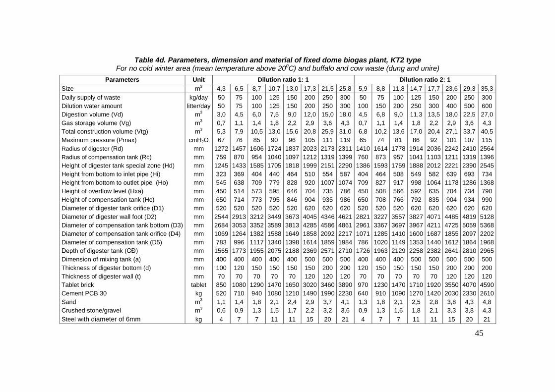
45
Table 4d. Parameters, dimension and material of fixed dome biogas plant, KT2 type For no cold winter area (mean temperature above 200C) and buffalo and cow waste (dung and unire)
Parameters Unit Dilution ratio 1: 1 Dilution ratio 2: 1
Size m3 4,3 6,5 8,7 10,7 13,0 17,3 21,5 25,8 5,9 8,8 11,8 14,7 17,7 23,6 29,3 35,3
Daily supply of waste kg/day 50 75 100 125 150 200 250 300 50 75 100 125 150 200 250 300
Dilution water amount litter/day 50 75 100 125 150 200 250 300 100 150 200 250 300 400 500 600
Digestion volume (Vd) m3 3,0 4,5 6,0 7,5 9,0 12,0 15,0 18,0 4,5 6,8 9,0 11,3 13,5 18,0 22,5 27,0
Gas storage volume (Vg) m3 0,7 1,1 1,4 1,8 2,2 2,9 3,6 4,3 0,7 1,1 1,4 1,8 2,2 2,9 3,6 4,3
Total construction volume (Vtg) m3 5,3 7,9 10,5 13,0 15,6 20,8 25,9 31,0 6,8 10,2 13,6 17,0 20,4 27,1 33,7 40,5
Maximum pressure (Pmax) cmH2O 67 76 85 90 96 105 111 119 65 74 81 86 92 101 107 115
Radius of digester (Rd) mm 1272 1457 1606 1724 1837 2023 2173 2311 1410 1614 1778 1914 2036 2242 2410 2564
Radius of compensation tank (Rc) mm 759 870 954 1040 1097 1212 1319 1399 760 873 957 1041 1103 1211 1319 1396
Height of digester tank special zone (Hd) mm 1245 1433 1585 1705 1818 1999 2151 2290 1386 1593 1759 1888 2012 2221 2390 2545
Height from bottom to inlet pipe (Hi) mm 323 369 404 440 464 510 554 587 404 464 508 549 582 639 693 734
Height from bottom to outlet pipe (Ho) mm 545 638 709 779 828 920 1007 1074 709 827 917 998 1064 1178 1286 1368
Height of overflow level (Hxa) mm 450 514 573 595 646 704 735 786 450 508 566 592 635 704 734 790
Height of compensation tank (Hc) mm 650 714 773 795 846 904 935 986 650 708 766 792 835 904 934 990
Diameter of digester tank orifice (D1) mm 520 520 520 520 520 620 620 620 520 520 520 620 620 620 620 620
Diameter of digester wall foot (D2) mm 2544 2913 3212 3449 3673 4045 4346 4621 2821 3227 3557 3827 4071 4485 4819 5128
Diameter of compensation tank bottom (D3) mm 2684 3053 3352 3589 3813 4285 4586 4861 2961 3367 3697 3967 4211 4725 5059 5368
Diameter of compensation tank orifice (D4) mm 1069 1264 1382 1588 1649 1858 2092 2217 1071 1285 1410 1600 1687 1855 2097 2202
Diameter of compensation tank (D5) mm 783 996 1117 1340 1398 1614 1859 1984 786 1020 1149 1353 1440 1612 1864 1968
Depth of digester tank (CĐ) mm 1565 1773 1955 2075 2188 2369 2571 2710 1726 1963 2129 2258 2382 2641 2810 2965
Dimension of mixing tank (a) mm 400 400 400 400 400 500 500 500 400 400 400 500 500 500 500 500
Thickness of digester bottom (d) mm 100 120 150 150 150 150 200 200 120 150 150 150 150 200 200 200
Thickness of digester wall (t) mm 70 70 70 70 70 120 120 120 70 70 70 70 70 120 120 120
Tablet brick tablet 850 1080 1290 1470 1650 3020 3460 3890 970 1230 1470 1710 1920 3550 4070 4590
Cement PCB 30 kg 520 710 940 1080 1210 1490 1990 2230 640 910 1090 1270 1420 2030 2330 2610
Sand m3 1,1 1,4 1,8 2,1 2,4 2,9 3,7 4,1 1,3 1,8 2,1 2,5 2,8 3,8 4,3 4,8
Crushed stone/gravel m3 0,6 0,9 1,3 1,5 1,7 2,2 3,2 3,6 0,9 1,3 1,6 1,8 2,1 3,3 3,8 4,3
Steel with diameter of 6mm kg 4 7 7 11 11 15 20 21 4 7 7 11 11 15 20 21
46
Module 4
CONSTRUCTION OF FIXED DOME BIOGAS PLANT
I. Selection of the site for construction
Selecting a suitable site is the first thing to do. For the plant to operate
conveniently and have long lifetime, for the construction to be easily carried out,
the selection of the site is based on the following requirements:
- Ensure adequate area for construction of the plant according to the design
dimensions. Economize area space and not affect the surrounding structures.
- Be far from low lands, lake and ponds to avoid flood, avoid places of
shallow groundwater to be convenient for construction and to keep the stability
and durability of the structure.
- Avoid the places with weak soils requiring complicated and costly
foundation treatment
- Avoid construction near big trees with intensive development of root
systems which might penetrate through the structure and damage it in the future.
- Be near to the source of feedstock to reduce transportation labor and cost. If
the biogas plant is combined with the treatment of toilet waste and wastewater
from the toilet and sewers, they must be connected directly with the digester so
that the dung and wastewater can flow by gravity to the digester, meeting the
sanitary requirements.
- Be near to the gas consumers to economize the gas conducting pipeline,
avoiding the pressure loss along the pipeline and limiting the risk of gas loss due
to the leakage.
- Be near to the effluent-storing place so that the liquid effluent can flow
directly to the reservoir, making it easy to transport away for use.
- The plant should be located in the sunny and wind-closed place for keeping
the high temperature, creating favorable condition for the fermentation and gas
generation.
- Be far at a distance at least 10 m away from the groundwater wells and
underground water tanks used for domestic water supply to prevent the
possibility of leakage causing pollution to them

47
II. Preparation of materials
The fixed dome biogas plant KT1 and KT2 are mostly constructed by
common material. To ensure the quality of the structure, the materials must meet
the following technical requirements:
1. Brick: The bricks used for the construction must be good, with
compressive strength of 75 kG/cm2. In term of shape, all sides and edges of brick
must be equilateral and well-burned, without swells or distortion, with the
surface being clean without attached sands or mosses. In case, we do not have
solid brick, we can use hole brick but the dimension of brick hole is not over 2
cm. To check the intensity of bricks, we can use simple method like this. We take
2 bricks, one brick is put horizontally at 1 meter height, and the other is
perpendicular to the first one. Then drop the brick. If it is not broken, it is the
good brick; otherwise the brick does not meet the standard.
2. Sand: The mortar for brick laying shall be made of coarse sands with grain
size not more than 3 mm. The mortar for plastering shall be made of fine sands.
It is generally required that the sands must be clean, without mixing with earth,
rubbish and other organic pollutants. In the case the sands does not meet the
requirements, it must be washed before use.
To check if dust and land mixed in sand, we use a glass bottle with even
section. Fill 1/3 of the bottle with sand and then pour water into the bottle, shake
the bottle for about 10-15 minutes to separate sand and impurities. Put the bottle
on a flat place and let the sand deposit in 1 hour. After that, we can observe that
in the bottle, upper layer is land and dust and the below layer is sand. Measure
the level of sand in the bottle; we can compare the sand level in the bottle after
the check and before shaking. If the difference of sand level before and after
shaking is under 5%, it can be concluded that the sand meet standard. Vice
versa, if over 5%, we must screen sand.
3. Cement: Portland cements of PC30 grade or higher shall be used. The
cement must be new, not being in clods or degraded.
4. Gravel, crushed stone: These are important aggregates for casting
concrete. The general requirements for these aggregates are: They must be clean,
without attached earth and organic matter. The size of these aggregates for cover
concrete is 1 x 2 cm, with compressive strength less than 300.
5. Mortar: For brick laying and plastering, sand cement mortar can be used.

48
Table 4.1. Mortar and PC 30 grade cement ratio*
Type of mortar
Ratio between cement and sand
(for 1m3)
Ratio for volume
Cement Sand Cement Sand
Brick laying mortar 296 kg 1,09 m3
1 5.5
Plastering mortar 410 kg 1,02 m3 1 4
* The ratio between mortar and cement is applied following the decision No.
24/2005/QDD-BXD dated 29th July 2007 for basic norm construction of Ministry of
Construction.
The ratio between water and cement of pure cement mortar is not exceed 0.4
6. Steel: Using normal construction steel with diameter of 6mm for casting
the concrete cover.
7. Pipes: The inlet pipe of the biogas plant usually have an internal diameter
of 150 mm or more and the outlet pipe often have an internal diameter of 100
mm or more. At present, in the market ready have PVC plastic pipe, so the
household should use this pipe for convenient. The general requirements are that
they must be water tight, not cracked, broken or holed, with clean surface for
good connecting with the masonry components.
III. Work construction
1. Marking the parts and identifying levels for the digester
The first thing is marking the parts and identifying levels for the digester.
a) Marking the parts
Firstly, we identify the digester. Digester location should be defined by
selecting the center of digester, firstly. We drive a stake at the point and tie a
string on the stake, mark the other end with a distance of the digester diameter
plus 25cm, then we tie the marked point with a stick. Use the stick to make a
ccircle. The location of compensation tank and mixing tank is determined
through relatively location of digester tank and space condition.
b) Identyfying the levels
we choose stable foundation level (in case, the household ready have stable
foundation and this level must ensure that slury is not upside down overflow
into stable) or overflow level (this level must ensure waste water can
automatically discharge from equipment) for level standards. After these levels

49
are identified, these levels should be marked on fixed thing like on the wall or
pillar. The height of biogas plant parts if defined based on these standard levels.
Figure 4.1. Marking the site of digester
2. Excavation
Depend on circle of excavation, geological condition so the digging depth is different. The digging depth is determined by slope of pit wall.
a) General requirements
- It is not allowed to disturb the original soil around and under bottom of the
pit.
- The canals for installing inlet pipe and outlet pipe will be split when
digester wall constructing up to the inlet and outlet site. No are split in advance
in order to prevent the collapse.
- Dug soil should be put into suitable place to avoid its impact on
construction.
- If the digester wall oozes water, it is stopped by a clay soil
- If there is groundwater: 1) it is compulsory to excavate a ditch around the
bottom to collect the water to the water collecting pit and 2) the water must be
pumped regularly from the pit during the construction.
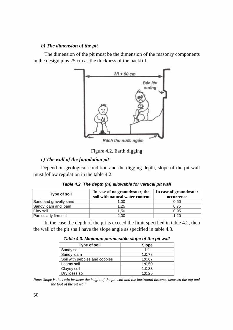
50
b) The dimension of the pit
The dimension of the pit must be the dimension of the masonry components
in the design plus 25 cm as the thickness of the backfill.
Figure 4.2. Earth digging
c) The wall of the foundation pit
Depend on geological condition and the digging depth, slope of the pit wall
must follow regulation in the table 4.2.
Table 4.2. The depth (m) allowable for vertical pit wall
Type of soil In case of no groundwater, the
soil with natural water content
In case of groundwater
occurrence
Sand and gravelly sand 1,00 0,60
Sandy loam and loam 1,25 0,75
Clay soil 1,50 0,95
Particularly firm soil 2,00 1,20
In the case the depth of the pit is exceed the limit specified in table 4.2, then
the wall of the pit shall have the slope angle as specified in table 4.3.
Table 4.3. Minimum permissible slope of the pit wall
Type of soil Slope
Sandy soil 1:1
Sandy loam 1:0,78
Soil with pebbles and cobbles 1:0,67
Loamy soil 1:0,50
Clayey soil 1:0,33
Dry loess soil 1:0,25
Note: Slope is the ratio between the height of the pit wall and the horizontal distance between the top and
the foot of the pit wall.

51
In case, the place of building does not permit slope digging, the wall of
foundation pit should be propped by wood barrier wall or steel.
d) The bottom of foundation pit
Bottom land under digging pit need security intensity and required stable
for sustains the digester loading capacity. In case, defined bottom land is not
enough condition for ensuring the biogas plant stable (as glutinous soil, sandy
soil underground water level), we must to have base consolidation method.
Simple methods for bottom base consolidation are described in the table 4.4
Table 4.4. The summarization of the methods for consolidation
of biogas plant
Degree and
group of soil
Terms of application Methods for
base
consolidation
Methods for
foundation
consolidation
I-1-degree
soil, I-2-
degree soil
- Soil with large hollow.
- Soil with little underground water.
- The depth of the weak soil layer was below 0.5 meter.
Use the method
of tightly
ramming.
Use the concrete
foundation.
- Glutinous soil, peat, mud, extended alluvial soil.
- Weak soil layer which was always submerged into water.
Driving in bamboo stakes or cajuput stakes.
Use the concrete foundation.
- The project area was rather large.
- The underground water level was not high.
Replacing the project base with a new one.
Use the concrete foundation.
- There was a sandy layer above or under the weak soil layer.
- Large project area, and there is no need to be hurry.
Use the previously load-added method.
Use the concrete foundation.
I-3-degree
soil, II-degree
soil
No need to
consolidate the
project base.
Use the concrete
foundation.
III-degree
soil, IV-
degree soil
There is no need
to consolidate the
project base.
There is no need
to consolidate the
project
foundation.
Note: See regulation on soil classification of Ministry of Construction

52
3. Building the foundation of the digester
The foundation of digester is
made by concrete with grade of
200. Depending on dimension of
digester so the thick of digester is
specific fixed on design. Concrete
must be poured following right
ratio. Firstly, we mixed cement,
sand and stone and at the same time
they are mingled until we obtain a
specific proportion. And next, the
water is poured in while the water
also is mingled with stones, sand
and cement until we achieve a
homogeneous concrete mixture which satisfies our required softness. After that,
we used bucket to move concrete into the digging pit. We poured from outermost
into inner. After completely pouring, we carefully rammed by hands or by
rammers. After being rammed, a square is utilized to make it flat and the sandy
ground surface is rubbed by plasterer's hawks so that the concrete surface will
become smooth and flat.
The foundation of the digester may be built of brick as design if the soil has
homogeneous structure of grade III and IV (use mandrel and crowbar to dig). The
bricks used for the building the foundation of digester must be solid of grade I,
with compressive strength of 75 kG/cm2. The thickness of brick layer must be at
least equal the thickness of concrete layer in design drawing. When construction,
the pieces of brick shall be placed in sequence following concentric circles, with
the seams not coinciding with each other and completely filled with mortar. First,
lay the outermost circle, and then lay in sequence the inner circles. Outermost
circle is foot of digester wall, so the pieces of brick shall be placed in length and
concentric seam. For inner circles, the brick shall be placed in cross and
perpendicular to the radius.
After the foundation has been built the water accumulated must be regularly
bailed out at least for 24 hours after the construction in order to keep the bottom
dry.
During the concrete casting operation and at least one day afterwards the
bottom of the foundation pit must be always dry, so that the concrete can
Figure 4.3. Building the foundation of the
digester

53
solidify. The construction of the digester walls shall be started only when the
concrete has been completely solidified.
4. Casting the concrete cover
The cover of the digester should be cast early when starting the construction.
The cover is truncated cone form. Steel plates can be used for making the form to
cast concrete of cover and used as maintaining tool for plastering digester collar.
The cover is thick, so it is not necessary to use reinforcing steel. The cover
is just cast by using cement and coarse sands with the ratio of 1 cement/3 sands/5
aggregated. The lower surface and lateral side must be plastered with a layer of
mortar and well polished. Then three gas- leakage protection layers shall be
applied like for the inner side of the digester.
If gas pipe can be arranged directly to the collar so we will place gas pipe at
cap. If gas pipe is sticked to the cap, we will place gas pipe to the cap’s heart. If
steel gas pipe is used, some small iron bar should be made to fix the pipe in
concrete block. If plastic gas pipe is used, a bigger pipe should be used to cover
the pipe and use glue to ensure that the pipe is attached steadily with mortar or
concrete. After pouring concrete, 2 handles will be put in the concrete block.
After being cast, the concrete cover must be kept in the shade and sprinkled
with water to ensure good solidification of the concrete and avoid cracking.
The dimensions indicated in the design must be strictly followed, so that
when placing the cover into the collar it is well fit with the inside wall of the
collar. Therefore, if the cover is cast earlier, during the construction of the collar
it can be adjusted to fit with the size of the cover.
Figure 4.4. Shape and cover
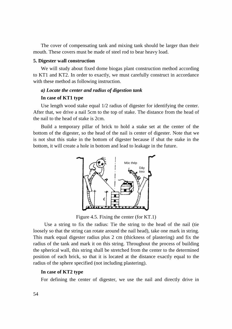
54
The cover of compensating tank and mixing tank should be larger than their
mouth. These covers must be made of steel rod to bear heavy load.
5. Digester wall construction
We will study about fixed dome biogas plant construction method according
to KT1 and KT2. In order to exactly, we must carefully construct in accordance
with these method as following instruction.
a) Locate the center and radius of digestion tank
In case of KT1 type
Use length wood stake equal 1/2 radius of digester for identifying the center.
After that, we drive a nail 5cm to the top of stake. The distance from the head of
the nail to the head of stake is 2cm.
Build a temporary pillar of brick to hold a stake set at the center of the
bottom of the digester, so the head of the nail is center of digester. Note that we
is not shut this stake in the bottom of digester because if shut the stake in the
bottom, it will create a hole in bottom and lead to leakage in the future.
Figure 4.5. Fixing the center (for KT.1)
Use a string to fix the radius: Tie the string to the head of the nail (tie
loosely so that the string can rotate around the nail head), take one mark in string.
This mark equal digester radius plus 2 cm (thickness of plastering) and fix the
radius of the tank and mark it on this string. Throughout the process of building
the spherical wall, this string shall be stretched from the center to the determined
position of each brick, so that it is located at the distance exactly equal to the
radius of the sphere specified (not including plastering).
In case of KT2 type
For defining the center of digester, we use the nail and directly drive in
Móc thép
Dây treo

55
bottom center of digester and leave 2cm for locating the center.
Figure 4.6. Fixing the center (for KT.2)
During construction dome wall string or stake must be used to check the
distance and the inclination of the brick to fix it exactly as digester radius in
design drawing.
b) Digester vault construction
Before being laid, the bricks must be immersed into water so that the brick is
dry outside but still moist inside.
Vault construction is built each line, in turn from underneath to top. Brick
shall lay horizontal; the bricks are arranged to make closed cycle. Each time
when laying a brick, the measuring string must be used to check the distance and
the inclination of the brick to fix it exactly, ensuring that the spherical wall is
evenly shaped, without any distortions.
Before laying the first layer of brick, it is recommended to use the measuring
string as a compass to draw a circle on the bottom surface. This circle determines
the line to fit the lower edge of the brick, ensuring that the distance of the each
brick to fix it exactly as the digester radius. When the first layers of brick near
the bottom have been laid, the wall should be plastered carefully on both inner
and outer side, as the digester usually leaks here. The plaster layer must be thick
and tightly pressed. The plaster must form round surface without angles. Glass
bottles may be used to press the plaster to make it even and smooth.
When the next layers of brick have been constructing then it is necessary only
to use the string to check the upper edge of the brick, and the same will continue
for the next layers above. Note: The vertical joints between bricks are not
allowed one above the other but alternate.

56
The construction and the plastering work of the dome wall should be carried
out at the same time and ensuring the plaster layers must be thick.
The first few brick layers may collapse when the mortar is still not solidified,
therefore when after laying the first layer it is recommended to use broken brick
or sticks to support outside to prevent the collapse.
When construction up to rows over center, slant bricks may collapse,
therefore when laying, the slant bricks must be kept by special method to prevent
the collapse. There are many measures to keep bricks as following:
- Use strings to tie one end to a brick or to a steel hook to temporarily hook
the brick, the other end is tied to a small stake which is fixed to the wall of the
foundation pit, or tied to a piece of brick acting as a counterweight and leave the
string to be stretched in the direction tangent to the outer surface of the sphere.
- In order to prevent bricks falling down when a circle is not completed, the
first brick of each row must be kept during construction. When some newly-
bricks on the row are laid the middle brick will be temporarily fixed by both
previous brick and latter brick. Therefore in this case, the anchor strings may be
removed and used for the new bricks.
Figure 4.7. The method keeps brick
during construction
Figure 4.8. Keeping brick during vault
construction
6. Installing the inlet and outlet pipes
When building the wall of the digester to the level where the pipe must be
installed, the pipes must be put on their places as design. Usually these places are
often leaking, therefore during the construction; special attention must be paid to
avoid complicated treatment in the future.

57
Both pipes must be straight, without angular places to prevent clogging.
Above the upper openings of the pipes shall not be any obstacle, so that a long
pole can be inserted into the pipe to unclog the pipe or stir the fermentation slurry
in the digester. The lower ends of the pipes must be symmetrically arranged on
opposite sides of the digester.
The pipes must be firmly fixed before using mortar to seal the pipe with the
wall of the digester, avoiding movement of the pipe before the mortar is
solidified.
Attention must be paid whether to use brick or soil to hold the mortar
beneath and behind the pipe to prevent it from flowing away.
The mortar used for plastering around the place of connection must not be
too wet.
It must be re-plastered when the mortar has been dry, especially below the
pipe and on the other side of the wall, as the mortar may flow out from the
connection.
The connection pipes in compensation tank as mixing tank and latrine
should careful connect as above.
Figure 4.9. Poured the mortar during installation of inlet and outlet pipes
7. Construction of the digester collar
The collar of the digester should be built in two steps: In the first step the
lower part of the collar up to the cover support is built after completing the
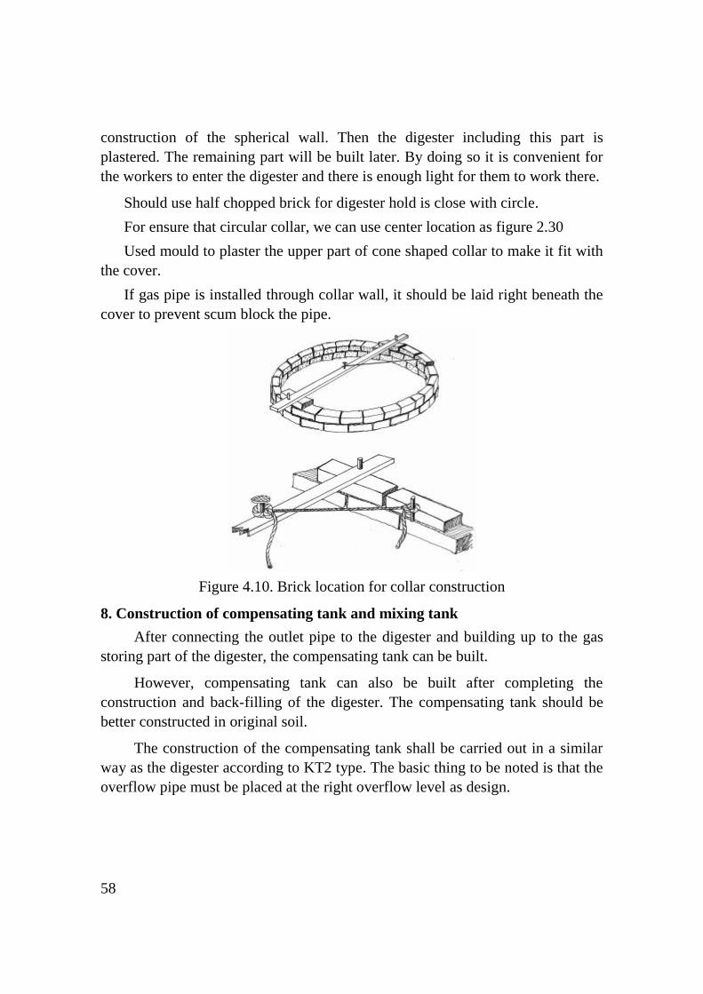
58
construction of the spherical wall. Then the digester including this part is
plastered. The remaining part will be built later. By doing so it is convenient for
the workers to enter the digester and there is enough light for them to work there.
Should use half chopped brick for digester hold is close with circle.
For ensure that circular collar, we can use center location as figure 2.30
Used mould to plaster the upper part of cone shaped collar to make it fit with
the cover.
If gas pipe is installed through collar wall, it should be laid right beneath the
cover to prevent scum block the pipe.
Figure 4.10. Brick location for collar construction
8. Construction of compensating tank and mixing tank
After connecting the outlet pipe to the digester and building up to the gas
storing part of the digester, the compensating tank can be built.
However, compensating tank can also be built after completing the
construction and back-filling of the digester. The compensating tank should be
better constructed in original soil.
The construction of the compensating tank shall be carried out in a similar
way as the digester according to KT2 type. The basic thing to be noted is that the
overflow pipe must be placed at the right overflow level as design.
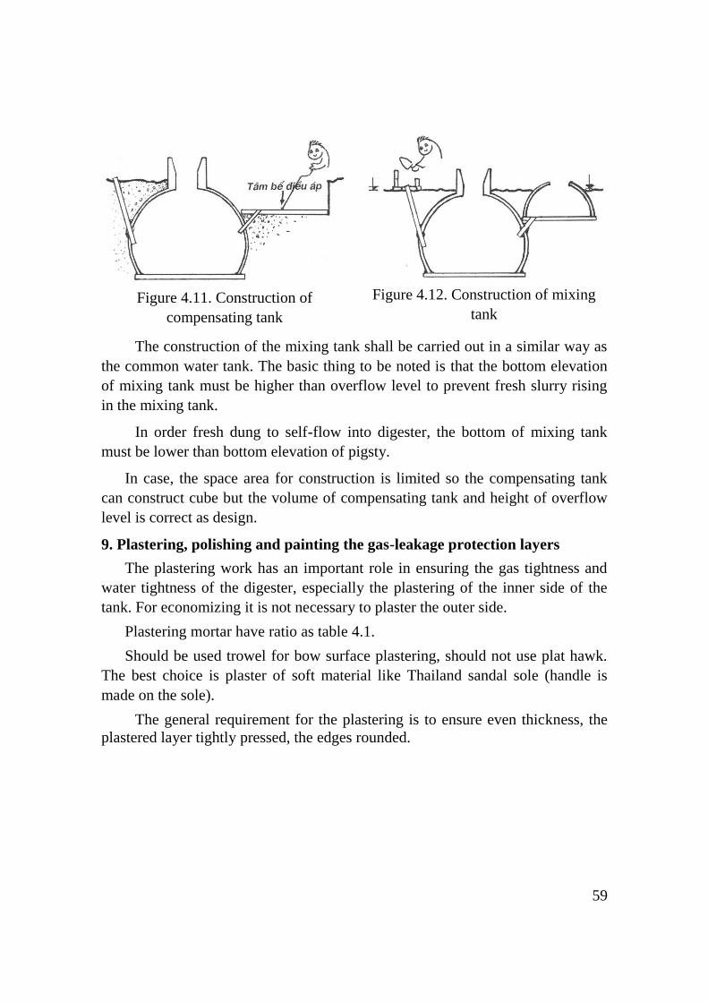
59
Figure 4.11. Construction of
compensating tank
Figure 4.12. Construction of mixing
tank
The construction of the mixing tank shall be carried out in a similar way as
the common water tank. The basic thing to be noted is that the bottom elevation
of mixing tank must be higher than overflow level to prevent fresh slurry rising
in the mixing tank.
In order fresh dung to self-flow into digester, the bottom of mixing tank
must be lower than bottom elevation of pigsty.
In case, the space area for construction is limited so the compensating tank
can construct cube but the volume of compensating tank and height of overflow
level is correct as design.
9. Plastering, polishing and painting the gas-leakage protection layers
The plastering work has an important role in ensuring the gas tightness and
water tightness of the digester, especially the plastering of the inner side of the
tank. For economizing it is not necessary to plaster the outer side.
Plastering mortar have ratio as table 4.1.
Should be used trowel for bow surface plastering, should not use plat hawk.
The best choice is plaster of soft material like Thailand sandal sole (handle is
made on the sole).
The general requirement for the plastering is to ensure even thickness, the
plastered layer tightly pressed, the edges rounded.
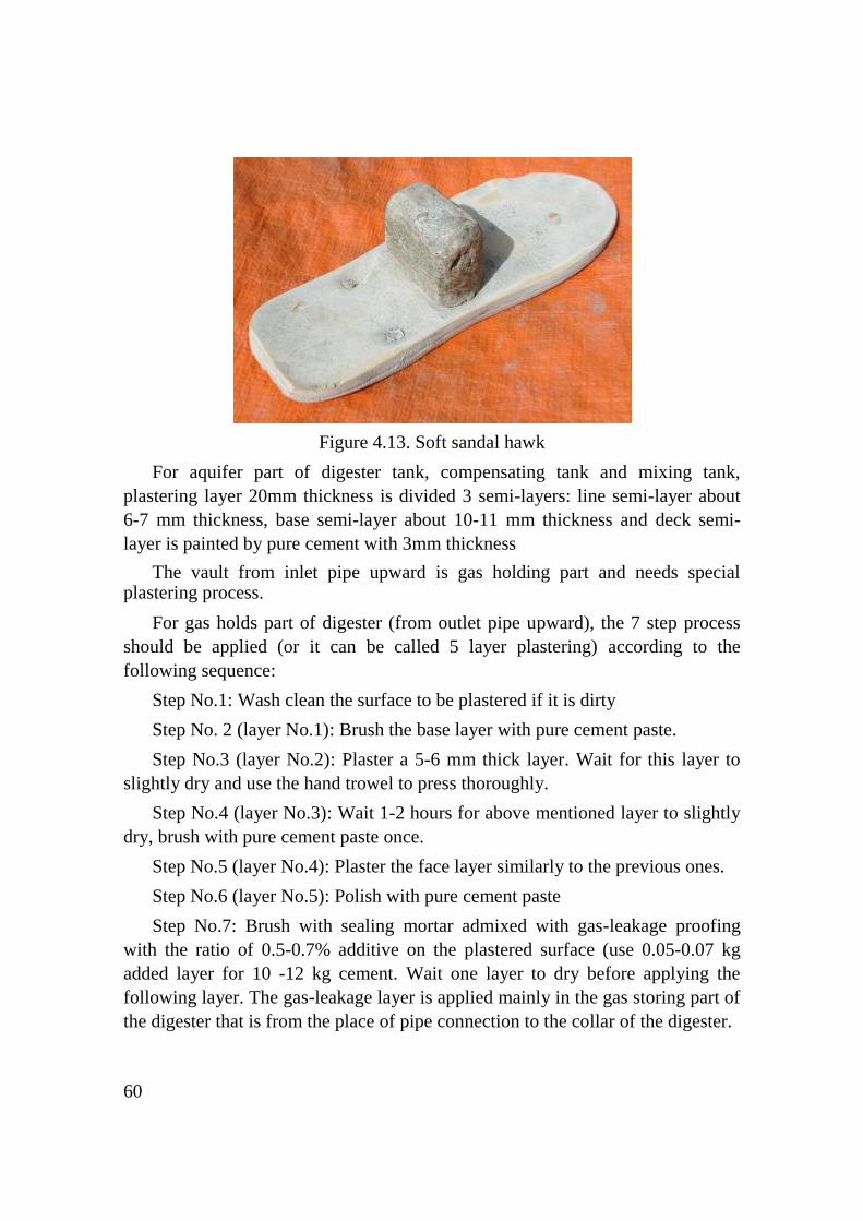
60
Figure 4.13. Soft sandal hawk
For aquifer part of digester tank, compensating tank and mixing tank,
plastering layer 20mm thickness is divided 3 semi-layers: line semi-layer about
6-7 mm thickness, base semi-layer about 10-11 mm thickness and deck semi-
layer is painted by pure cement with 3mm thickness
The vault from inlet pipe upward is gas holding part and needs special plastering process.
For gas holds part of digester (from outlet pipe upward), the 7 step process
should be applied (or it can be called 5 layer plastering) according to the
following sequence:
Step No.1: Wash clean the surface to be plastered if it is dirty
Step No. 2 (layer No.1): Brush the base layer with pure cement paste.
Step No.3 (layer No.2): Plaster a 5-6 mm thick layer. Wait for this layer to
slightly dry and use the hand trowel to press thoroughly.
Step No.4 (layer No.3): Wait 1-2 hours for above mentioned layer to slightly
dry, brush with pure cement paste once.
Step No.5 (layer No.4): Plaster the face layer similarly to the previous ones.
Step No.6 (layer No.5): Polish with pure cement paste
Step No.7: Brush with sealing mortar admixed with gas-leakage proofing
with the ratio of 0.5-0.7% additive on the plastered surface (use 0.05-0.07 kg
added layer for 10 -12 kg cement. Wait one layer to dry before applying the
following layer. The gas-leakage layer is applied mainly in the gas storing part of
the digester that is from the place of pipe connection to the collar of the digester.

61
10. Back-filling
This work could be carried out step by step in the case the masonry block
has been sufficiently solidified and underground water is low.
It is best to use sands or coal ash for back filling, especially the space
around the digester foot.
For KT.1 model, attention must be paid to the lower part of the digester
below its center, and the material must be well compacted, otherwise the bottom
of the digester may crack when slurry is fed into the digester.
During the construction, the foundation and lower end of wall of digester
are plastered carefully to prevent water proofing.
The back filling must be carried out carefully, in order to avoid collapse and
break of the digester and other structures in the surroundings.
Figure 4.14 Back filling
The back-filling should be carried out by about 15 cm thick layers; each
layer should be sprinkled with water and tightly compacted before back-filling
the next layer. Attention should be paid to put the material evenly all around the
digester to avoid breakage and cracking of the wall.
Special attention should be paid the connections of the inlet and outlet
pipes, at the bottom of the compensating tank, otherwise the bottom of the
compensating tank may be subsided and the pipes are broken.
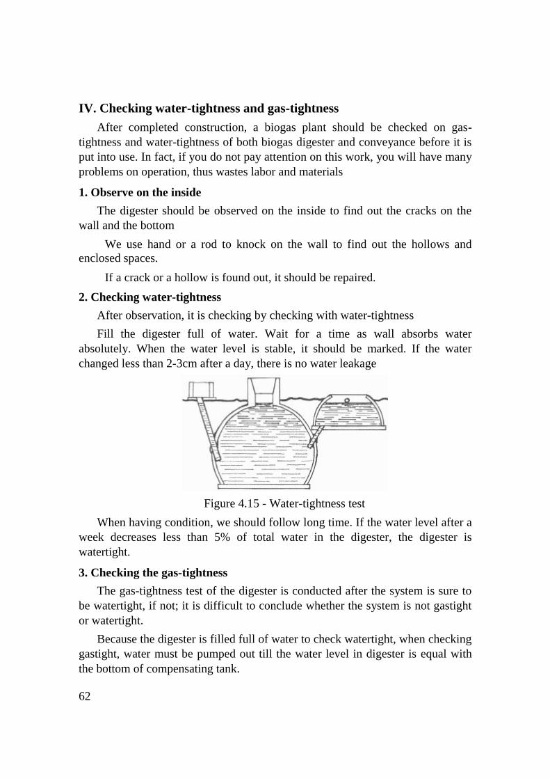
62
IV. Checking water-tightness and gas-tightness
After completed construction, a biogas plant should be checked on gas-
tightness and water-tightness of both biogas digester and conveyance before it is
put into use. In fact, if you do not pay attention on this work, you will have many
problems on operation, thus wastes labor and materials
1. Observe on the inside
The digester should be observed on the inside to find out the cracks on the
wall and the bottom
We use hand or a rod to knock on the wall to find out the hollows and
enclosed spaces.
If a crack or a hollow is found out, it should be repaired.
2. Checking water-tightness
After observation, it is checking by checking with water-tightness
Fill the digester full of water. Wait for a time as wall absorbs water
absolutely. When the water level is stable, it should be marked. If the water
changed less than 2-3cm after a day, there is no water leakage
Figure 4.15 - Water-tightness test
When having condition, we should follow long time. If the water level after a
week decreases less than 5% of total water in the digester, the digester is
watertight.
3. Checking the gas-tightness
The gas-tightness test of the digester is conducted after the system is sure to
be watertight, if not; it is difficult to conclude whether the system is not gastight
or watertight.
Because the digester is filled full of water to check watertight, when checking
gastight, water must be pumped out till the water level in digester is equal with
the bottom of compensating tank.

63
Covered closely digester and sealed joint by clay.
Connected the digester with manometer.
Added more water in digester to increase the gas pressure inside.
Watched if pressure reaches up to 50 cm water column.
The digester should then be left for 24 hours. If the water column in
manometer will change very small, i.e. 1 – 2 cm, the digester is shown to be
gastight.
Figure 4.16. Checking gas-tightness
After checked and found a gas leak, the method check up on gas leak carries
out the similar inner tube of bicycle testing. Soapy water may be put on gas taps,
gas cocks, joints, pipe line and fitting to check for leaks. Bubbles will form if there
is a leak.
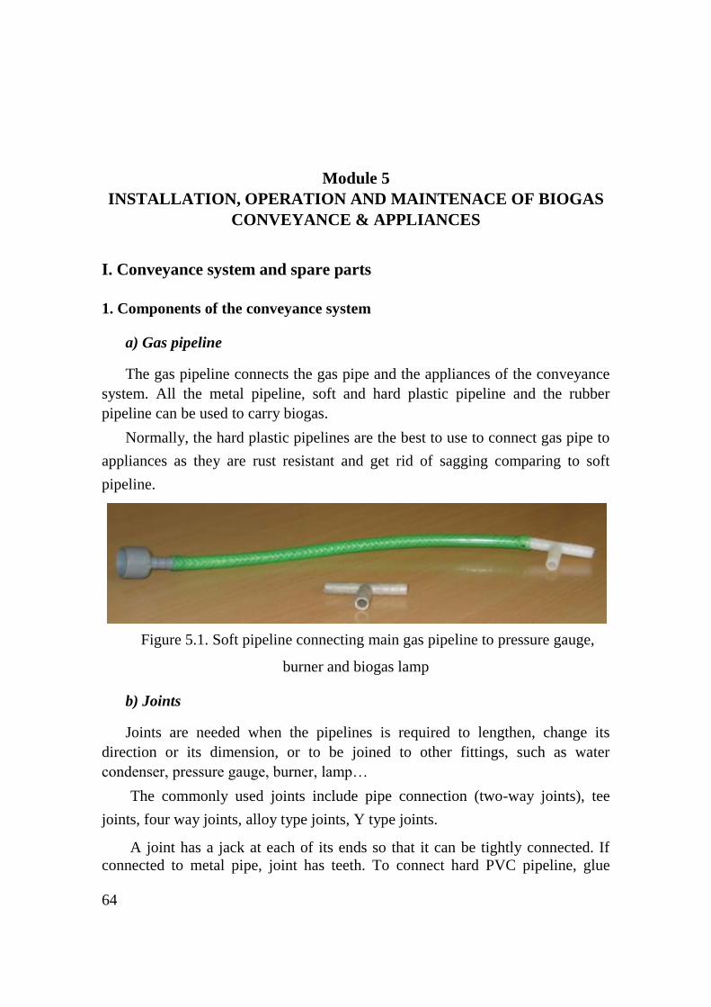
64
Module 5
INSTALLATION, OPERATION AND MAINTENACE OF BIOGAS
CONVEYANCE & APPLIANCES
I. Conveyance system and spare parts
1. Components of the conveyance system
a) Gas pipeline
The gas pipeline connects the gas pipe and the appliances of the conveyance
system. All the metal pipeline, soft and hard plastic pipeline and the rubber
pipeline can be used to carry biogas.
Normally, the hard plastic pipelines are the best to use to connect gas pipe to
appliances as they are rust resistant and get rid of sagging comparing to soft
pipeline.
Figure 5.1. Soft pipeline connecting main gas pipeline to pressure gauge,
burner and biogas lamp
b) Joints
Joints are needed when the pipelines is required to lengthen, change its
direction or its dimension, or to be joined to other fittings, such as water
condenser, pressure gauge, burner, lamp…
The commonly used joints include pipe connection (two-way joints), tee
joints, four way joints, alloy type joints, Y type joints.
A joint has a jack at each of its ends so that it can be tightly connected. If
connected to metal pipe, joint has teeth. To connect hard PVC pipeline, glue

65
should be used.
Figure 5.2. Joints: pipe connection, tee-type joint, glue
c) Gas valve
Gas valves are used to open or close pipelines.
The commonly used valves include ball valve, plug cocks and latex pipe
metal and plastic valves which are available in the market.
The ball valves are easy to use, abrasion resistant and gas-tight.
Before installation, valves should be tested for gas-tightness by soaking into
water and blow at both status of opening and closing. If bubbles occur in the
places of not gas-transporting line, valves are leaking. Sometimes, using oil for
valve to operate easily and keep valve tight.
Figure 5.3 Ball valve

66
d) Water condenser
Biogas always contains saturated water. Vapors may enter the pipeline, and
condense into water. Pipeline is stuck if condensate is not discharged. Thus,
water condenser should be installed to solve this problem. There are various
ways to fix condensers. The commonly used methods are expressed as follows:
* Bottle condenser
A bottle condenser can be fixed to either a vertical or a horizontal pipeline.
When the condensate has accumulated to a certain amount in the bottle, pour it
out and fix the bottle to the pipeline again.
Figure 5.4. Bottle condenser
* Water tap
A tee joint is fixed to the lower end of the vertical pipeline outside of the
house; a transparent pipe with a tap is fixed to the lower end of the tee joint.
When condensate has accumulated to a certain amount in the transparent pipe,
turn on the tap to remove the water.
0,005
Biogas

67
Figure 5.5. Water tap
* Automatic water drain
A U-shaped pipe is fixed to the lowest point of the pipeline. The height X of
pipe open to air must be longer than maximum pressure.
The condensate in the U-shaped pipe will rise in the open column so keep the
gas not going out of the pipe. When there is too much water accumulated, it will
overflow
Figure 5.6. Automatic water drain
e) Pressure gauge
Pressure gauge shows us both the current pressure and the reserves of biogas
in the digester. The high pressure is the more reserves of biogas in the digester
and vice versa.
* U-shaped pressure gauge
U-shaped pressure gauge is transparent a pipe
(made of glass or plastic) fixed on a scaled board.
The shorter branch connects to the pipeline while
the longer branch is exposed to the atmosphere.
Water column in the pipe is equal to each other
and to the zero position when pressure gauge is not
connected to pipeline.
When gas pressure is higher than atmosphere
pressure, water level in the open branch will rise up.
The difference of water levels of the two water
columns presents gas pressure by centimeter water
column.
Figure 5.7. U-shaped
pressure gauge

68
U-shaped pressure gauge is also a safe valve provided that the total height of
water column in pipe is equal to designed maximum pressure.
When the gas pressure surpasses the maximum pressure, all the water in it
will overflow into the bottle and biogas will escape from the bottle to the air.
If gas pressure is too high and push water out of the tube, a bottle with a hole
at the bottom should be fixed to the longer branch of the pipe to keep the water
from overflowing.
When gas is used or discharged, gas pressure drops below the maximum
pressure; water flows back into the pipe and keep the gas from escaping. Thus,
the bottle has two functions of both preserving water in the pipe and closing
automatically when gas pressure is under maximum pressure.
In order to make it easy to read the water gauge, color floating object, e.g tiny
pieces of colored foamed plastics can be placed on the surface of the water in the
pipe.
* Clock pressure meter
Clock pressure meter is available in the market.
The installation and utilization of clock pressure meter is simple. However, it
does not have function of safe valve like U-shaped pressure gauge.
One scale in clock pressure meter indicates a value equal to 10 centimeters of
water column in U-shaped pressure gauge
Figure 5.8. Clock pressure meter
2. Determination of the internal dimension of the pipeline

69
When gas is transported in the pipeline, gas pressure drops due to friction
with pipe. The reduction depends on property and dimension of the pipe. The
longer the pipe is, the less the gas pressure is and; the bigger the diameter of the
pipe is, the less the reduction of pressure.
To make calculation simple, the selection of internal dimension of pipe is
carried out basing on the diagram 5.9. In the diagram, the vertical axis presents
the length of pipe and the horizontal axis presents the biogas flow rate.
Respective internal diameter of pipe is presented with diagram portions.
Figure 5.9 Diagram for determining internal diameter of pipeline
Example: A household owns a biogas plant and needs to convey gas to places
of stove and lamp where 25 meters from the plant. The household uses two
stoves and 3 lamps. Supposed that the gas consumption of stove and lamp is 480
litters per hour and 140 litter per hour respectively. Demanding amount of gas
consumption is as below:
For cooking: 2 stoves x 480 litters/hour = 960 litters/hour (maximum)
For lighting: 3 lamps x 140 litters/hour = 420 litters/hours (maximum)
Total: 1,380 litters/hour = 1.38 cubic meters/hour
Using the diagram, X1 has ordinate of 25 and abscissa of 1.38; thus, the
internal diameter of pipe should be at least 12 mm (1/2 inch).

70
3. Installation of biogas pipeline
a) Installation of the outdoor pipeline
The outdoor pipeline can be installed in the air or underground. For the
former, it is easy to observe. If plastic pipe is used, pipeline should be sheathed
so as to resist aging. For soft plastic pipe, pipeline should be propped up so as not
to be stagnating water.
The pipeline should slop 1 percent toward the digester or toward the water
condenser.
Figure 5.10. Installation of outdoor pipeline
b) Installation of indoor pipeline
In the house, the pipeline should not be buried in the ground or laid casually
on the ground.
The indoor pipeline should be installed in the place where the pipeline is not
exposed to sunshine or prone to be hit by external force.
The horizontal indoor pipeline should be fixed along the wall of the roof at
the height of over 1.7 meter from the ground.
The indoor pipeline slope should be no less than 0.5%. It slopes from the
pressure gauge to the main pipe and the appliances.

71
For the sake of safety, the pipeline should be over at least 30 meters from
biogas lamps and the heating transmission line.
Figure 5.11. Installation of indoor pipeline
The best way to lay out the pipeline in the house is to keep the pipeline as
near as possible to the appliance.
Gas tightness should be tested by soaking joints in the water or covering the
pipeline with soap fluid then blow into the pipe. Bubbles will appear where there
is gas leakage.
4. Maintenance of biogas pipeline and appliances
Frequently drain the condensate water, check pipeline for crushing or aging
to replace or repair the damaged parts.
Maintain valves; sometimes test gas tightness then lubricate the valves in
order to open and close easily.
Add water to keep enough water in U shaped pressure gauge.
5. Trouble shootings and remedies
Troubles Causes Remedies
1. Gas does not reach the appliances
1. Leakage - Check potential leaking places like joints, valves with soap fluid
2. Pipe is too small - Replace with bigger pipes
3. Pipe is blocked - Discover blocked places by segment and solve the blockage at site
2. Gas flow is unstable Water is stagnate in the pipe - Drain condensate water

72
II. Biogas appliances
1. Biogas stove
a) Structure
Figure 5.12. Diagram of biogas burner
1. Gas tube; 2. Gas valve; 3. Flame port;
4. Mixing chamber; 5. Air regulating shutter; 6. Burner head; 7. Nozzle
Nozzle
Nozzle should have a narrow orifice of small diameter to increase the gas
pressure at the orifice. The diameter of orifice depends on capacity of the burner,
properties of gas as well as gas pressure.
Air regulating shutter
Air regulating shutter has function of adjusting the opening of air regulating
gate, hence adjust the amount of gas provided for the burner.
Mixing chamber
This part plays a role of mixing biogas with oxygen of surrounding air to
have a combustible mixture of gas. The mixing ratio decides the combustion of
gas mixture. Then the gas mixture is injected to the orifice.
Head
Head is composed of chamber and flame ports. Mixture of biogas is
distributed to every port homogeneously in order to fulfill complete combustion.
b) Operation and maintenance
* Operation
- Burner cock should be close at “off” position when no burning to get rid of
gas leakage or unsafely for user.
- Completely close the air regulating shutter at the end of mixing tube.
73
- Ignite and give flame toward the flame ports.
- Open gas valve of burner; this valve can be maximum opened.
- Put the pot on the head of burner as the flame is weak and long thus cover
the surrounding of pot.
- Adjust the air shutter until the noise of flame is heard.
- Regulate gas valve and air shutter so as the flame is blue and has the height
of 25 to 30 mm, the flame reaches the bottom of pot. This is the perfect
combustion as efficiency can reach 60 percent.
* Maintenance
Keep flame ports clean regularly so as to ensure the fine injection of gas and
high efficiency of burner. Head of burner should be free of chocking with
corrosion matters. Gas valve should be smoothly operated to get rid of breaking.
c) Trouble shooting and remedy
Troubles Causes Remedies
1. Pressure indicated on pressure
gauge is high but no flame
1. Burner is not suitable for
biogas
Adopt the burner which is
fine in technical performance
2. Quality of gas is
unqualified with too much
hazardous gas
Check the operation of
biogas plant (maybe too
much feedstock, too much
urine or toxic matters in
digester)
2. Pressure indicated on pressure
gauge is high, but the fire is weak.
1. Flame ports are too small,
and the biogas supplied to
the burner is not enough
Clean the bore of the valve
or change the valve
2. The nozzle is choked Clean the nozzle
3. Sometimes the fire is strong
and sometimes is weak and even
goes out. Water column of
pressure meter goes up and
down.
There is accumulated water
in conduit which affects the
normal transportation of
biogas
Remove the accumulated
water in the pipe line
4. Flames keep away from the
ports. When the pot is taken
away, flames lift off or goes out,
flames from the ports in the last
two outer circles lift off
1. The flame ports are less in
quantity and the total area of
ports is small.
Adopt the burner which is
fine in technical performance
2. Biogas pressure is too high Regulate the inlet pressure
of biogas to rated pressure
3. The ports are choked. Clean the ports. If failed,
change the fire cover.
5. There are flames at periphery,
but no flame in the middle.
1. The injection of primary air
is not enough.
2. The ports are too near to
pot bottom, so the second air
1. Lift the pot bottom so that
to set a proper distance
between the ports and pot
bottom.

74
Troubles Causes Remedies
is less. When thermal is
large, it causes fire
suppressed.
3. Use unsuitable burner
2. Adopt the burner which is
fine in technical performance
6. The flames are weak. Flames
occur at nozzle.
The ports are larger. After a
certain time of combustion,
the ports are too hot. It
causes backfire when biogas
pressure is low.
1. Adopt the burner which is
fine in technical performance
2. Properly increase the
height of pot supports.
3. Properly increase inlet
pressure of biogas.
7. The flames are long and
waving
The primary air is not enough Regulate the air shutter. If
failed, widen the air shutter.
8. The peripheral flames lift off
after a certain time of use of the
burner
1. Flame ports are choked
2. The primary air is not
enough
Enlarge the ports with a
wire. If failed, change a new
fire cover.
9. The flames are red or yellow Too much or too less air Adjust air regulating shutter.
2. Biogas lamp
a) Structure
Figure 5.13. The structure of biogas lamp
1. Nozzle and injector 2. hanger 3. Connecting piece 4. Inlet for the primary air 5. injector 6. nut 7.
washer 8. upper cover 9. clay head 10. air vent 11. clip pin 12. lift reflector 13. glass cover
75
Nozzle
Nozzle is connected to the injector. The nozzle hole is very small hole, which
is normally about 1 mm.
Injector
Injector is a straight tube made of copper. Its functions are the same as that of
burner and also of holding other parts of the lamp.
Inlet for the primary air
In the injector there are two symmetric holes of 5 mm diameter near to the nozzle,
which are used as the inlets for primary air. The inhalation of primary air can be
controlled by turning injector backward or forward to regulate the distance between the
nozzle and the inlets for primary air.
The clay head
The clay head is made of refractory material and connected to injector.
Mantle
Mantle is tied to the clay head. When burning, it provides bright light.
Light reflector
Light reflector is used to focus rays of light as well as to protect mantle.
There are many air vent holes in the light reflector.
Glass corer
Glass cover has function of protecting mantle and preventing the wind from
extinguishing the light and insects getting into the lamp. There is also air vent
hold in the glass cover.
b) Operation and maintenance
* Operation
- Using the mantle for the first time
Mantle should be opened to form a hollow ball then tied to the clay head.
Ignite a fire
Open the gas cock and gas regulator little by little and then, give the fire
close to the mantle. Attention should be paid by giving fire at side of mantle
so that prevent of darkening the mantle. The mantle should be lit and allowed
to burn.
Wait for the full bright of the lamp. Normally, the mantle reaches its
bright after a couple of minutes and it makes little noises. Adjust regulator so

76
that the mantle is at its brightest. It is usually unnecessary to adjust the gas
for the following burn.
To turn off the lamp by closing gas cock.
- Using the mantle after the first time
Give the fire close to the mantle
Open the gas cock
Adjust regulator if necessary
Close the gas cock to turn off the lamp.
* Maintenance
- After burning the first time, attention should be paid to mantle as it shrunk
and easy to break.
- When change new mantle, clay nozzle, injector and reflector should be
cleaned.
- Not touch the used mantle with naked hand or be hit by some falling object
from the used mantle because it has radioactive matters.
c) Trouble shooting and remedy
Troubles Causes Remedies
1. The mantle is blown away and damaged
1. The clay head made refractory material is broken and hence an opening is formed
Replace the damaged one with a new one.
2. The gas pressure is too high Adjust gas cock to reduce gas pressure
3. The mantle is not fixed well or it is shocked while igniting
Change the mantle then tie carefully
4. The mantle is pierced by insect bite or crashed with hard objects
Change the mantle and try to avoid mentioned causes.
2. Though biogas is enough, the lamp does not burn bright or the light is red
1. The eject of the nozzle is too small or blocked, and accordingly there is not enough biogas coming into the lamp
Clean the clay nozzle or widen injector. If failed, change the injector.
2. The aperture of the nozzle is so large that it is unable to draw enough air into it.
Adjust the gas flow and quantity of primary air.
3. The wind-regulator is not well adjusted so that it is unable to draw enough air into the lamp.
Readjust
4. The mantle is of poor quality and become damp.
Change the mantle
3. The light keeps flickering
1. The lamp is of bad quality and can not burn steadily.
Use a new lamp
2. There is condensate in the pipeline, Clear the pipeline of

77
which block the passage of gas intermittently.
condensate.
4. The brightness of the light decreases gradually
The quantity of gas in the digester is reduced, and this results in a drop of gas pressure
Regulate the valve to increase biogas inflow into the lamp.
5. The flame appears on the mantle
1. There is not enough air coming into the lamp
Open wider the wind-regulator
2. The nozzle is not in the right position or it does not stand up-right
Adjust the nozzle or replace it with a new one.
3. Too much biogas come into the lamp
Regulate the gas valve to reduce the quantity of biogas.
3. Biogas water boiler
a) General introduction
Biogas water boilers follow the same principle of other fuel used water
boilers such as natural gas water boiler and LPG water boiler.
There are two kinds of water boilers available:
* Water boiler without storage tank
The water boiler without storage tank has the following charateristics:
- No store hot water
- Boil water right away to meet the demand close to place of using boiling
water.
- Convenient if there is limitation of area and space
- Unable to provide hot water if the amount of water needed is much
* Water boiler with storage tank
The water boiler with storage tank has the following characteristics:
- Cheaper cost in comparision with the former.
- Having bigger and more cumbersome structure than the former.
The latter is currently more popular than the former in Vietnam. There are
available water boilers in the market but not yet without testing for the quality.
Normally, these boilers are modified from LPG ones so that the quality and
safety is not guaranted by the suppliers.
b) Structure and operation
The water boiler is composed by an atmospheric nozzle and injector and a
water tank.
For device with storage tank, water is storaged in the tank and the injector
will provide heat for boiling water.

78
For device withouth storage tank, cold waer goes through a place of pipes
(heat exchanger) that laid in the burning chamber. The injector supplies the
burining chamber biogas for heating. After that, water burns up to temperature
needed.
The device is usually equipped with controling units. There are an automatic
igniter that gives fire when open water, valves for reducing temperature and
pressure and a heat adjuster.
Figure 5.14. Device without storage tank
Figure 5.15. Device with storage tank
4. Biogas engine
a) General introduction
Generally speaking, biogas engines belong to the type of internal combustion
engines.
Nowadays, people have created specialized engines used biogas as fuel.
However, we also can modify the available engines in the market to the engines
can use biogas.
The following engines below are able to use biogas as fuel:
- Four-stroke petrol engine
- Four-stroke diesel engine
Two-stroke petrol engine is not suitable for the modification because it uses
the mixture of petrol and oil for lubricating the engine.
Biogas engines are usually used to power the water pump, automobiles like
light trucks or generator etc.
The consumption of biogas as follows:
0.45 to 0.54 cubic meter per hour for one horsepower.
0.62 to 0.70 cubic meter per hour for one KW.
Smoke
Heat exchanger
Nozzle and
injector
Inlet and outlet for
water
Outlet for hot water
TPR valve
Anot
Deep pipe
Heat adjuster
Discharge vavle
Inlet for cold water

79
b) Modification of petrol engine
The modification of four-stroke petrol engine to use biogas is the simplest.
To modify the engine, it must be added a biogas-air mixer to the carburetor to
supply the engine with biogas. Owing to the igniter, the mixture of biogas and
air can burn easily.
Figure 5.16. Biogas-air mixer
After modification, the engine is wholly fueled by biogas. To start easily, it
can use petrol for starting. The engine after modification still can use petrol when
short of biogas.
c) Modification of diesel engine
For diesel engine, the temperature at the end of compression stage is
normally not over 700oC. At this temperature, the biogas-air mixture can burn.
While the ignition temperature of biogas-diesel mixture is 814oC hence it is
unable to burn at the end of compression stage.
There are two methods of modification:
- Turning engine to the engine with igniter: add a magnetic generator and a
spark plug to the original diesel engine so as to change the compression ignition
engine into an Otto electric ignition cycle engine. After modification, the engine
is wholly fueled by biogas. However, the refitting is complicated and costly thus
not commonly applied.
- Refitting engine into a biogas-diesel-fueled engine. In this method, add a
biogas-air-mixer to the air filter of the diesel engine like in the four-stroke petrol
engine. A little amount of diesel is ejecting into the cylinder right before the
compression stage so that to ignite the biogas-air mixture to burn. Normally, it
needs 15 to 25 percent of previous diesel consumption amount is enough.
With these methods, there are two advantages:
+ Less cost for modification while saving 80% of diesel.
+ Able to use diesel when short of biogas.

80
Module 6
OPERATION AND MAINTENANCE OF BIOGAS PLANT
I. Operation of a biogas plant
1. Starting operation
After checking and the plant was found watertight and gastight, it can be put
into operation.
a) Preparing initial input materials
The initial should be filled to the bottom of compensating tank (zero
level). If there are not enough materials, the dilution ratio is higher than normal.
* Feedstock is animal dung
The first filling feedstock is determined by the digester volume. Normally,
for this material, dilution ratio is 1 to 2 liter of water per 1 kg of waste.
Therefore, the first filling feedstock in the family scale plant is 330 to 500 kg per
1 m3 of the digester.
For example, with a biogas plant having a 1m3 requires amount of input
material for the first time filling is:
Input material Dilution ratio 1:1 Dilution ratio 2:1
Animal waste 500 kg 330 kg
Water 500 litter 670 litter
For the first filling, pig waste and cow waste should be used to produce
biogas quickly because the animal waste contain methane – producing bacteria,
thus help to quicken the fermentation and production of biogas.
Waste should be collected for some days prior to the start of the first filling.
Feedstock should be in the fresh state of strong animals. It must not be allowed to
use the waste of sick animals, which were injected with penicillin. An antibiotic
is maintained in the waste a long time, even a month, when this waste fed into
digester, it will be kill anaerobic bacteria.
Avoiding the dry of manure, it is necessary to pour the water every day. It is
impossible to soak manure in water. So it will be produced biogas quickly

81
* Feedstock is plants
The residues of agricultural plants can be used as initial feedstock in case not
enough waste. They can replace partly or totally waste.
The input material for 1m3 digester as follows:
With water hyacinth, water weed: 400 - 500 kg.
With dry corn stalks or rice stalks: 120 - 150 kg.
This kind of materials should be pre-treated before being put into the
digester. The method is as follows:
The plant wastes are crushed and chopped into small pieces about 1÷3 cm
long, piled up in the layers, each layer about 50 cm thick. A little animal waste
should be added over each layer. Then water is added daily to keep wet.
The period of pilling depends on the ambient temperature. The summer, this
pilling should last 10 – 15 days, whereas in winter, it should keep for a month.
Digester can be used for pretreatment of input materials. Composting
feedstock in digester for some days, then digester is covered to change to
methane producing stage.
Note: we should also not feed too much straw in digester because it is very
difficult to disintegrated and easy to formulate scum. This scum layer will hinder
the gas to be released from the digestion slurry.
b) Dilution and mixing feedstock
The feedstock should be mixed with water to create a suitable environment
for chemical reactions. Mixture between water and waste is called feedstock.
For animal waste (dung and urine), it usually takes about 1 to 2 litters of
water per 1kg of animal waste or from 3 to 4 litters of water per 1kg of fresh
dung, depending on the moisture content of feedstock.
For wastes of fresh plants as water-fern and vegetations, the dilution ratio is
about 0.4 to 0.6 litters of water per 1 kg of fresh plant:
Dilution water should be fresh water, neither acidic nor alkaline. The water in
natural pond and lake are better than tap-water.
If there is water in the digester, need to adjust dilution water amount and then
when this is filled into the digester that will become correct content.
82
c) Filling feedstock in the digester
The feedstock can be charged through manhole, the outlet or the inlet. The
filling is done as quickly as possible.
We also can use the digestion slurry in mixing tank of constructed biogas
plant to fill the newly built plant to increase methane – producing bacteria and for
quickly gas production.
If the manhole of fixed dome plant or gasholder of floating gasholder plant
was covered, all gas valves should be opened to blow air out of the digester and
pipeline, thus preventing digester from cracking because of high pressure.
First, plant feedstock is filled in the digester and then animal waste is added.
2. Monitoring quality and using gas
Digester after being charged with feedstock is covered and all the gas valves
are closed to create anaerobic environmental (no oxygen) for chemical reactions.
The first, low metal content so the biogas may not burn and hard smell.
Therefore it should all be allowed to escape of gas sometimes. When the gas
burns well by burner that means it is ready for use
Biogas fire is slight blue color and invisible by eyes, therefore, for easy
observation, it requires shade of sunlight. Moreover, because there are many
impurities in the first produced biogas, the flame will leave the ports of burner.
So for checking quality of gas it must be put a pot in the burner to limit lifting of
flame and the burner easy burning.
The period of gas – producing depends on the kind of feedstock and the
climate. If materials are cows or pigs waste, in sunlight and hot climate, gas is
produced after a few hours, even some hours. If feedstock is other feedstock or
plant residue, in cold climate, gas is produced more slowly (may be week or
more).
Caution: To prevent explosion: There must be no smoking or flame in the
outlet of pipeline!
3. Daily biogas plant operation
a) Daily filling the digester
* General requirement
After initial feedstock filling about 10 – 20 days, feedstock can be fed and
digested residue are taken out. The amount of digested residue taken out is equal
to the amount of feeding. The feedstock is fed into the inlet and the residue is

83
removed from the outlet. The slurry surface in the case of gas pressure is zero
must be equal to compensating tank bottom (at zero level).
It needs to monitor the operation of digester after a time in order to calculate
the correct amount of additional feedstock and obtain the yield of biogas as
designed.
If too much or too little feedstock is filled, the yield of biogas will decrease
because of unstable operation of the plant.
* Daily filling feedstock amount
The amount of the daily feedstock per digestion m3 is described in table 6.1
Table 6.1 Daily feeding feedstock per digestion m3
Region Local Daily filling amount (kg/day/m3)
I The north mountainous region 6 - 9
II Almost the country 8 - 12
III The South Vietnam 11 - 16
* Waste dilution
Reasonable dilution will to create a suitable environment for chemical
reactions. However, if filling excessive water, the feedstock’s will too many be
dilution, the waste is not treated and pushed out digester. It leads to bad gas
production and environmental unhygienic
For the feedstock are plants as water-fern and straw, the dilution water filling
until covering the pretreated - plants
* Filling the digester
After mixing properly, feedstock may be filled through manhole, the slurry
has been mixed the cover over the inlet pipe is removed and the slurry is allowed
to flow into the digester. This work is very useful to stir the digestion slurry.
* Impurities and toxic must be avoided
The compounds which badly affect the fermentation and plant devices should
be eliminated. They consist of:
- Soil, sand or stone ….These will be accumulated in the bottom of digester
- Wood, stick or branch of tree…These are difficult to digest.
- Chemicals: Soap, oil, detergent, dye, pesticide, and insecticide, antibiotic
injected animal …These will kill the bacteria and stop gas production

84
b) Stirring the fermentation slurry
Stirring the fermentation slurry is very useful because this work helps to
increase the gas production. This also helps new feedstock closely contract with
bacteria as well as help chemical reactions happen quicker. However, it should
also break up the scum layer.
The methods of stirring the fermentation slurry:
- Moving a long stick up and down the inlet several times.
- Recycle: Sucking water from the outlet, pouring back to the inlet. This
method can add more anaerobic bacteria living in outlet to contact with the fresh
slurry, where is very low density of anaerobic bacteria. Thank to this method the
number of methane – producing bacteria is increased. This method is called bio
return-flow method.
Stirring should be done daily for 5 – 10 minutes in several times.
c) Breaking – up the scum layer
The scum layer blocks gas – production. So breaking – up the scum layer is
essential.
A correct dilution also limits the forming of scum. If the slurry content is too
low, scum will be formed easily.
In the fixed dome biogas plant, the slurry surface is always down and up,
hence its surface area is narrowed or expanded and it is leading to reduction of
scum.
Stirring can also limit the scum layer.
If the scum layer is too thick, it should be removed from manhole.
If the plant is operated well (remove cellulose from materials, optimum slurry
content, stirring daily), scum will be formed slowly, thus is not harmful and
needs not be removed.
d) Monitor of gas pressure
A low gas pressure always is under level of using and can be caused by some
following possible causes:
- Leak in gasholder or gas pipeline. It should be located and repaired.
- Reduce of gas production. The reasons must be found out and overcome.

85
- Gas – pressure rises up and down, unstable flame means that there is water
stacked in pipe. It should be removed.
e) Measurement of gas production
If the plant is operated correctly, gas – production will be stable.
Gas production can easily be measured when a gasholder floating is used. In the
fixed – dome plant, it is measured by a manometer or the yield of gas – used daily.
An unusual reduction in gas production means that the biogas plant is operated
incorrectly or there is a leakage. It should find reasons quickly to repair.
II. Maintenance of biogas plant
Maintenance of biogas plant is mainly removing sediment and scum removal.
A thick scum layer which reduces gas production should be removed every
year at careless operation of the plant or after few years if the plant is well-
operated.
The sediment in the bottom of digester pit is made of solid compounds
namely soil, sand, stone, and piece of broken brick. It has been thickened for
times and sticks the inlet and outlet. It should be removed from the digester. For
the biogas plant fills the plants, the sediment is usually removed in the time
changing new batch materials.
The removing sediment is better done before the winter, so the plant will be
operated well during the winter.
III. Using safety
1. Preventing Explosion
Biogas can explode when there is 6 to 25 percent biogas mixed with air.
When biogas plant installation, we must to pay attention as following:
+ The installation of the pipeline must avoid the places with the risk of fire or
explosion to prevent fire.
+ The lamp and stove must be installed in the suitable place for good
illumination, easy operation, not affected by wind, not subjected to vibration
which might cause the fall of the mantle, far from inflammable object. So that all
the air in the gasholder, gas dome and pipeline need to be removed before use.
When opening the manhole cover, re-feeding materials or in the rooms
there is gas leakage, there should be no smoking, no fire and no oil lamp using in
this area. The gas leakage is discovered by the smell of gas.
86
+ When lighting on stoves and lamps, it should follow the requirement as
mentioned in biogas lamp and stove using.
2. Preventing asphyxiation
Biogas is not toxic, but it does not remain alive. However if the hydrogen
sulfur content in biogas is high, biogas will be noxious gas. If content of
hydro sulfur is high, the biogas also is harmful. It is required to prevent
asphyxiation and poisoning, therefore:
- The site for placing stove and lamp must be clear and air blown in order
exhausted smoke or gas leakage gets out easily avoiding user from suffocation
- When replacing the mantle must to implement as requirements in
biogas lamp using part
When the gas pipeline is installed in the closed room, it will be very
dangerous if the gas leaks out. Therefore when smelling gas, please open all the
doors and clear of air in the room, then the leakage should be located and
repaired.
When any worker needs to enter the plant, the following procedures should
be followed:
- The cover of the digester is opened and removed;
- Wait until all gas in the plant escapes, or blow air into the plant to ventilate
it. Before any one enters the digester it is best to make a check with an animal.
An animal should be lowered into the digester and brought up again about from 5
to 10 minutes, if the animal is still alive so the person can to go down digester.
- A worker going into the digester should use a safety wire. It should have
another person out side to monitor and help him.
IV. Common troubles and remedies
Table 6.2. Common troubles and remedies
Troubles Causes Remedies
1. No gas or little
1. Poisoning of fermentative
slurry
Re-check quality of feedstock and
replace with another feedstock
2. Bad quality dilution water Re-check the quality of water as pH,
water source
3. Lack of methane producing
bacteria
Wait a time or add more bacterium.
4. Coal weather - Keep warm for digester
- Wait re-warm climate

87
Troubles Causes Remedies
5. Gas leakage Check the place easy for gas leakage
as gas holding part
6. Thick scum on top of slurry
and no place for escapement gas - Removing scum.
- Install a stirring device.
- Ensuring appropriate dilution ratio of
fermentative slurry.
- Do not using feedstock with high
content in lignin and wax
7. Scum and too much sediment Removing scum and sediment
8. Fermentation slurry is too
acidic (pH<7)
Added appropriate amount of lime or
ash
9. Fermentation slurry is too
alkaline (pH>8) Wait a time
10. Too little feedstock daily. Increase daily amount of feedstock into
digester
2. Not enough gas
for consumption
Too little gas Look up the first item above
Gas consumption rate is higher
than gas generating capacity - Used burner in appropriate
combustion
- Modified burner or appliance.
- Reduce the consumption.
3. Too much gas
production
Too much input feedstock - Less feedstock should be put in daily.
- Replace another suitable burner.
- More using gas.
4. Materials are not
fed into the
digester.
Too solid feedstock Add more water.
Inlet pipe blocked - Un-choke inlet pipe
- Take out all inorganic matter in
feedstock.
Inlet blocked due to solid in the
digester too thick
Removing solid.
5. Gas smelts bad. Too much H2S in the biogas - Reduce the amount of human and
chicken dung in the feedstock
- Install a filter of H2S
6. Metal devices
turn to black.
Too much H2S in the biogas As item 5
7. The running
plant stops
producing gas.
The fermentation process is
poisonous.
Remove all contents of the digester,
and then restart feeding.

88
Module 7
PROJECT TECHNICAL STANDARDS
Objective of project is construct biogas plant to ensure quality, effective operation and long lasting, so biogas plant construction process as quality control of project must be close comply with sector standard on small biogas plant issued by Ministry of Agriculture and Rural Development. Project makes also standard more detail and defines project standard on acceptance. These regulations will help Provincial Biogas Project Division as user to manage and implement more easily.
I. Standard on location for biogas plant constructed
- 5m far away from water well or water tank serving for living purpose;
- Not closed to perennial plant;
- The distance from the digester to gas-used place at least 2m;
- The digester is free from load weighed down by a heavy construction like foundation of kitchen, bathroom…
II. The standards on construction material and biogas appliances
- Sand: clean sand, which not mixed with impurity and had good adhesive property;
- Brick: the first/A grade of quality, without inflated surface, internal-spongy, and having no big through hole (if has the hole’s diameter is not bigger than 2cm)
- Cement: Portland cement with grade of PC30 or higher, still in good quality and not to be curdled;
- Gravel crushed stone, broken brick: Clean surface, not attached with earth or organic matter ;
- Dome-gas pipe: made of steel coated with zinc or Tien phong plastic with grade I of quality, the internal diameter of pipe is 15mm up. Dome gas pipe is installed in the cover of digester or at the highest point of digester’s neck, which is below digester’s cover;
- Main valve: made of bronze/steel coated with chrome/plastic, main valve connects dome-gas pipe with main gas conveying-pipe;
- Main gas conveying-pipe: must have internal diameter at least 12mm when installed for the length below 30m and 15mm for the length up or equal 30m respectively;
- Pressure meter: if using U-tube as pressure meter it must have scale indicator and the water level in two-tube must be in line with the “zero mark” on the scale when the gas’s pressure in digester is null, the pressure meter is installed in a place which is easy to observe;

89
- Biogas stove and biogas lamp: stove and lamp are atmospheric type, they must have pre-air-intake part, safety and efficiency in use.
III. The standards for acceptance
1. The standard for biogas plant
- The structure and dimension must be in accordance with the design drawing;
- The model of biogas plant must be suitable for geological condition at construction place;
- The cover of digester can be sealed with a thin of cement layer but it must be easy opened when required:
- The cover of compensating tank must have check-hole that will be used for taking bio-slurry, agitating digested liquid and destroying stuck at outlet-pipe;
- Encourage farmer build the track for surplus animal bath-water to limit too much amount water input into digester;
- Encourage farmer attaches toilet to digester;
- Encourage farmer build the third tank to keep bio-slurry as fertilizer;
- Construction work must follow strictly the construction procedure of the project; the gas storage part of digester must be treated with air-tight proof.
2. The standard for gas pipe and biogas appliances
- - Dome-gas pipe: made of steel coated with zinc or Tien Phong plastic with
grade I of quality, the internal diameter is ≥15mm:
- Installing main gas-valve is compulsory
- The main gas conveying-pipe line must have suitable diameter with the
distance from digester to gas use-place, and is installed in a way to avoid water
stays
- The pressure meter is installed at a place which is easy to observe. If U-tube
is use as a pressure meter the height of whole water column in two-tube is not
exceeded the maximum pressure designed;
- Stove is in atmospheric type and has pre air-intake part;
- Stove and lamp must be at least 50cm away from inflammable substance;
- The site for placing stove and lamp must be clear and air blown in order
exhausted smoke or gas leakage gets out easily avoiding user from suffocation.
Note: Only normal operating biogas plant in the project is accepted.
The acceptance documents sent to BPD to receive subsidy includes: the
origin copy of form 3, form 7, and form 9. Povincial Biogas Plant Division will
keep the duplicated copy.

90
IV. The standard on operation and using biogas plant
1. Maintenance work
- The digester’s cover is sealed with a layer of clay that must be always kept in
water, do not place too heavy thing on the top of cover;
- For the case, in the area where clay is not available or the digester’s cover is
blown up due to strong gas pressure the user can seal digester’s cover with a thin
layer of cement, if using an additional cover on the upper of the first one the
additional cover must be observed and opened when required;
- The ratio of water/dung must be suitable, building a track for surplus animal
bath water is encouraged to easily adjust dilution ratio and isolate detergent or
dung form ill animal;
2. Efficiency of biogas plant
- Biogas plant doesn’t have gas leakage at the digester neck;
- The gas production is sufficient as designed.

91
Module 8
QUALITY CONTROL
I. What is quality control?
Quality control (QC) includes activities that are carried out and implemented in order to ensure the products meet the set up quality requirements.
QC activity of the project is implemented during the duration of project implementation following the below contents:
+ To build and perfect the procedures and standards on quality management
+ To study, complete and perfect and manage the quality of the model design.
♦ Manage the activities of related bodies at every levels who are in charge of quality of biogas plants
♦ Do the quality control for the biogas plants at the stages:
- Under construction,
- Completed construction and plants in operation
II. The importance of quality control
Quality is the highest priority of any project. Hence, as an indispensable consequence, quality control is considered as a core activity to ensure the success of the Project. In boundary of the project “Biogas program for animal husbandry sector in Vietnam” quality control is implemented to bodyguard the quality of the construction and the operation by the users to comply with the quality standards of Project. The satisfied users are the main and effective extension media for the promotion of the technology and vice-versa.
To manage the quality of biogas digester, it is important to establish the quality management mechanism of high effectiveness and feasibility. After being issuance, this mechanism is considered as regulations and instructions for all activities related to quality control of every levels in the Project as well as for control other factors which may affect the quality of the Project.
One of the major activity in quality control component is manage the quality of the biogas digesters. The quality control focus on the following issues:
The validity of the biogas plant;
Quality of masons and trained users;
Quality of the construction;
Quality of the operation and maintenance by the users;

92
Quality of after-sale service by mason/masonary group.
III. Role and responsibility of biogas mason in QC quality
The task of quality control will carried out by all bodies from the National Biogas Project Division (BPD), the Provincial the provincial Biogas Project Divisions (PBPD), by provincial/district techniciansa and biogas masons. The roles and responsibilities of biogas mason is summarized as follows:
- Perform the construction according to the model design; if modification, it should be permitted by district technicians and PBPD;
- Curve plant code on the surface of plant or where never close to the biogas plant and easy to watch. The code should be carved according to “Guideline for the implementation activities in province”:
Biogas project Vietnam – The Netherlands
Code of biogas mason – number of biogas plant of district
Type: ………….. Size: ………………
Date of starting work: ……………….;
- Assist district technician to provide guidance on operation and maintenance for users;
- Perform repairment and maintenance when requested by users;

93
Module 9
BIOSLURRY UTILIZATION
Bio-slurry - a byproduct of decomposition process of substances - has two
forms of solid and liquid.
Bio-slurry comprises three elements namely biogas digested effluent, solid
residue and scum.
- Biogas digested effluent: Liquid flows from digester to compensation tank
then slurry pit through overflow outlet.
- Solid residue: Solid lies on the bottom of digester.
- Scum: Solid floats on the surface of fermented fluid in digester.
I. Chemical and nutrient composition of bio-slurry
Bio-slurry contains 93% of water, 7% of dry matters and 4.5% of organic
matters, of which 2.5% is inorganic matters.
- The bio-slurry discharged from a digester contains:
- Solid-form organic matters (humus),
- Soluble nutrients (having fertilizer and conditioner properties),
- Trace elements (Cu, Zn, Fe, Mn...),
- New cells formed during digestion.
The composition of bioslurry depends much on input raw materials. NPK content in bioslurry differs for different input raw materials and dilution ratio. In Vietnam, input materials are commonly pig dung, cattle dung, human excreta and poultry dung. Table 9.1 below presents the results of analysis carried out by Hanoi Agricultural University (HAU) in 2005. the content of NPK in bioslurry
can be variable in the range as follows:
Table 9.1. The content of NPK in bio-slurry
N (g/l) P2O5 (g/l) K2O (g/l)
Biogas digested effluent 0.37 – 0.80 0.099 – 0.31 0.32 – 0.56
Solid residue 0.562 0.376 0.96

94
If converted to available chemical fertilizers in the market, one ton of digested effluent equal to: 0,8 – 1,73 kg of urea fertilizer, 0,5 – 1,55 kg of phosphate fertilizer; 0,5 – 0,9 kg of potassium fertilizer. One ton of solid residue equal to: 1,2 kg of urea fertilizer; 1,88 kg of phosphate fertilizer; 1,6 kg of potassium fertilizer.
Table 9.2 below shows analysis results on heavy metals in digested effluent
carried out by NIAH in 2004.
Table 9.2 Content of heavy metals in digested effluent
Heavy metal Pb (ppm) As (ppm) Hg (ppm)
Analysis of NIAH 0.00331 0.0041 0.00093
National Standard for water 0.01 0.01 0.001
From table 9.2, it is able to conclude that the amount of heavy metals in digested
effluent is much lower than that of National standards for running water. Hence, it is
secure to use the product as fertilizer for crops and fishpond.
II. Use of bio-slurry as fertilizer for crops
1. Scientific basis and benefits of using bio-slurry as fertilizer for crops
Bioslurry is organic fertilizer which has two important properties of rich in
nutrients and clean. This organic fertilizer holds slow-and-quick ating manurial
effect concurrently as it has the following elements:
+ Digested effluent. The digested effluent is a quick-acting fertilizer
containing many kinds of water-soluble nutrient content, and crops are easy to
assimilate its nutrient content after it is applied to soil (the effect of nutrient is
very high).
+ Solid residue. Solid residue contains many kinds of nutrient, organic
matters and nutrient absorbers with high efficiency.
Up to now, bioslurry has been widely applied in agricultural farming as
fertilizer for crops, mushroom cultivation and seed treament…
2. Benefits
a) Soil improvement
Bio-slurry holds plenty of organic matter so when long-term application of
biogas fertilizer is beneficial to:
- Serve the function in amelioration of soil
95
- Increase the action of soil microbes (especially aerobic bacteria) and
promote decomposition of organic matters, enhance and increase the fertility of
soil.
- Improve the structure and physicochemical properties of soil. Improve the
air regime of soil to make it spongy, lower compressive strength and improve the
capability of holding water, absorbing water and easy to break and beneficial to
cultivation.
- Reduce soil erosion by wind and water.
b) Effect of increasing crops’ yields
According to a joint research between Biogas Project and the National
Institute of Fertilizer and Soil in 2004, the use of 60 cubic meters of digested
effluent diluting with water at the ratio of 1/1 to fertile 1 hectare of cabbage helps
the yield of cabbage increase 24 percent as compared to the control that only use
NPK (with dosage of 200 kg of nitrogen, 100 kg of phosphate and 100 kg of
potassium). After one harvest, farmers can save: 60.76 kg of urea fertilizer, 65.40
kg of super phosphate and 47.5 kg of potassium fertilizer. In addition, using
digested effluent as fertilizer help decrease of 50 percent pesticide consumed to
control leafhopper per crop.
c) Effect on control of crop diseases and pests
- Using bioslurry (of high quality) may restrict the development of green
mites on vegetable, cotton and wheat; spot leaf disease on some crops; in general,
it decreases the development of pests up to 30 to 100 percent.
- Digested effluent, 48 hours after it is admixed with 10% of pesticide, will
bring an insect population decrement of more than 60%. Hence, the application
helps reduce the amount of pesticide used, reduce toxicity and alleviate the
pollution of environment as well as cut down the agricultural cost.
- The demonstration plots in Hanoi, Binh Dinh, Tien Giang, Hai Duong and
Thai Nguyen … have shown that the use of digested effluent as fertilizer for
crops increase the pest resistant ability of crops.
3. Application methods of bio-slurry as fertilizer for crops
Bio-slurry can be used to replace fully or partly chemical fertilizers. Digested
effluent can apply directly on foot, as foliage top-dressing or add some organic
fertilizers for fertilizing crops.
To preserve the amount of nitrogen in digested effluent, super phosphorate
can be added of 2 to 5 percent by weight. Experiment of the Institute of Energy

96
in 1990 showed that with this method, digested effluent can be reserved up to 50
days with the loss of nitrogen is 15 to 25%. If no super phosphate is added, the
loss of nitrogen may be up to 70%.
To increase the efficiency of bioslurry, composting method should be used.
Composting process
Step 1: Dry rice straw and grass until they get withered. Put them in layers on
the hard ground (or in pits) with roofing next to the compensation tank. Add 0.5
to 0.7% by weight of lime.
Step 2: Apply digested effluent onto organic layers and mix well these layers
so that the effluent imbues well the organic material. The amount of digested
effluent should be 3 times more than organic material.
Attention must be paid on the keeping humidity of the heap by watering
digested effluent; the amount of digested effluent is 15 kg per 100 kg of material
should be applied for the heap. When the temperature of the heap reach 40-50o,
more digested effluent needed. Then, compress well to avoid nutrient loss.
Step 3: After 2 to 3 week, mix the heap up down and add super phosphate of
2% by volume, then compress it well as before.
After 1-2 months of composting, the compost fertilizer has the characteristics
similar to manure and they are ready for use.
The rationally combined application of bio-slurry with chemical fertilizer can
make up each other’s deficiencies and alleviate the contradiction between the
needs of crops for nutrient elements and the fertilizer supply of soil. The mixed
application can accelerate the solution and adsorption of chemical fertilizer in
soil and stimulate the crop to assimilate nutrients, thus lessening the loss of
nitrogen and enhancing the utilization ratio of chemical fertilizers. This also can
reduce the consumption of chemical fertilizers, increase the efficiency use of
fertilizer as well as cut down the investment for chemical fertilizers.
Table 9.3 Formulas using bio-slurry as fertilizer for crops
Crop Region Harvest
Amount of fertilizer per ha
Basing fertilizer
Additional fertilizer

97
Crop Region Harvest
Amount of fertilizer per ha
Basing fertilizer
Additional fertilizer
Paddy
rice
Red
river
delta
Spring
harvest
8 - 10 tons of
compost
30 - 32 kg N
80 - 90 kg
P2O5
Hasten branch: 20 kg N; 2,5 - 5 tons of digested
effluent
Hasten rice in ear: 30 - 32 kg N; 15 - 30 kg K2O;
3,7 - 7,5 tons of digested effluent
5 days after blossom: 2 - 3 tons of digested
effluent
Main
harvest
6 - 8 tons of
compost
20 - 25 kg N
50 - 60 kg
P2O5
Hasten branch: 15 - 17kg N; 2 - 4 tons of digested
effluent
Hasten rice in ear: 20 - 25 kg N; 3 - 6 tons of
digested effluent
5 days after blossom: 1,5 - 2 tons of digested
effluent
Cuu
long
river
delta
Winter-
spring
harvest
25 - 30 kg N
20 - 30 kg
P2O5 (before
harrowing)
Hasten branch: 17 - 20 kg N; 3 - 5 tons of digested
effluent
Hasten rice in ear: 25 - 30 kg N; 25 kg K2O; 4,5 -
7,5 tons of digested effluent
5 days after earing: 3 - 5 tons of digested effluent
Summer-
autumn
harvest
22 - 30 kg N
30 - 40 kg
P2O5 (before
harrowing)
Hasten branch: 15 - 20 kg N; 3 - 5 tons of digested
effluent
Hasten rice in ear: 22 - 30 kg N; 4 - 6 tons of
digested effluent
Peanut Infertile
soil
Spring
harvest
9 tons of
compost
10 - 15kg N
40 - 80kg
P2O5
15 - 30kg
K2O
2 - 3 compound leaves: 2 - 3 tons of digested
effluent
Nearly flowering: 2 - 3 tons of digested effluent
Maize 8 - 10 tons of compost; 15 - 30
kg N; 60 - 80 P2O5 ; 80 kg K2O
Tree has height of 10 - 15cm: 15 - 30kg N; 25 kg
K2O; 2 - 4 tons of digested effluent
Tree has height of 60 - 70cm: 10 - 15kg N; 1 - 2
tons of digested effluent
Cabbage 25 tons of compost
100 kg P2O5
30 kg N
25 kg K2O
Ratio of digested effluent and water is 1:1
Recover green: 20 kg N; 2 tons of digested effluent
Small leaf stretch out: 30 kg N ; 25 kg K2O; 1,5
tons of digested effluent
Big leaf stretch out: 30 kg N; 1,5 tons of digested
effluent
Ready to roll: 20 kg N; 1 tons of digested effluent
Roll: 20 kg N; 10 K2O; 1 tons of digested effluent

98
Crop Region Harvest
Amount of fertilizer per ha
Basing fertilizer
Additional fertilizer
Kohrabi 8 tons of compost
33 - 40 kg N
90 - 100 kg P2O5; 50 - 60 kg K2O
Recover green: 8 - 10 kg N; 5 - 6 kg K2O; 1 - 1,2 tons of digested effluent
20 - 25 days after last harvesting: 12 - 15 kg N; 10 - 12 kg K2O; 1,5 tons of digested effluent
35 - 40 days after growing: 15 - 20 kg N; 10 - 12 kg K2O; 2 - 2,5 tons of digested effluent
Green cabbage
20 tons of compost; 20 kg N; 50 - 70 kg P2O5; 17 kg K2O
7 - 10 days after last harvesting: 14 kg N; 10 kg K2O; 1 tons of digested effluent
15 - 20 days after growing: 10 kg N; 10 kg K2O; 1 tons of digested effluent
Centella 7 days after last harvesting: 7 kg N; 0,8 tons of digested effluent
14 days after last harvesting: 7 kg N; 0,8 tons of digested effluent
21 days after last harvesting: 7 kg N; 0,8 tons of digested effluent
Potato 25 - 30 tons of compost
40 kg N; 150 kg P2O5; 60 kg K2O
15 – 20 days after growing: 20 kg N; 30 kg K2O; 2 tons of digested effluent
15 – 20days after first application: 15 kg N; 35 kg K2O; 2 - 3 tons of digested effluent
Tomato 10 - 15 tons of compost
50 - 80 kg P2O5
50 - 60 kg K2O
12 - 15 days after growing: 15 - 20 kg N; 25 kg K2O; 3 tons of digested effluent
After vigorous blossom: 15 - 20 kg N; 25 kg K2O; 3 tons of digested effluent
After first harvesting : 15 - 20 kg N; 2 tons of digested effluent
III. Use of bio-slurry as additional pig feed
1. Scientific basis and benefits of bioslurry as addtional pig feed
When organic mateials are digested anaerobically, a significant fraction is
reduced to ammonia, some of which is taken up by growing bacterial biomass
and converted to new amino acids (AA). With cattle waste, increases of 230% of
total amino acids have been measured after digestion. In addition, considerable
quantities of vitamin B12 are synthesized during digestion. Preliminary results
from work indicate concentrations of over 3,000 mg B12 per kg dry sludge. In
comparison, the main sources of B12 in animal feeds, fish and bone meal,
contain 200 and 100 mg/kg respectively.
99
Many researches show that: total ash and total nitrogen (N) in the influent and bioslurry do not change significantly during fermentation.
Table 9.4. Number of parasite eggs in input materials and bio-slurry
Varieties Parasite eggs in input
materials (eggs/ml solution)
Parasite eggs in bio-slurry (eggs/ml
solution)
Decreased rates (%)
Total 218.4 3.21 98.0
Ascarid 182.5 2.35 97.0
Plagiorchis arcuatus (fluke worm)
23.2 0.75 99.4
Hookworm 5.4 0 100.0
Bug 0.61 0 100.0
Filaria 6.61 0 100.0
Yellow intestinal worm Not found Not found
The extermination of parasite eggs in the anaerobic digestion has two forms:
the deposition of eggs and eggs die because of unfavourable environment in the
digester. The biogas fermentation has special changing function. Some biological
inactive matters like acetic acis, cell active element and grown hormones… are
found in bioslurry. The quantity of crude protein and crucial AA and B vitamins
increases. There are available active elements as well as variable hydronaza
(especially string hydrolysis enzyme).
Scientific documents lead to conclusions, as follows:
- Bio-slurry contains a great number of nutrients crucial to animal growth like
macronutrients of Ca, P, N; mineral micronutrients of Cu, Zn, Mn, Fe; many
kinds of protein and many AA (including 9 indispensable AA for animals). Bio-
slurry also has many enzymes that help increase feeling hungry, food
transformation of home animals. If composted materials are cattle manure, the
composted products contain many vitamin group B (B1, B2, B12...).
- Most worm eggs and intestinal flatworm eggs are killed (96-98%) or their
parasitization capability is lost. The remainders produce parasitic disease (on
swine) reduces to 1-1.5%.
- Some bacteria, especially disease bacteria on swine which badly affect meat
quality like Salmonella, T. pasterianus, Baccilus engsipilatosu and Baccilus
perfringers are not found in bio-slurry except small amount of E.Coli (about 12
bacteria in 1 ml).

100
2. Benefits
a. Increase gaining in weight
- In experiments on piggy swine, supplementing conventional feed with 15-
18% digested effluent increase weight 11.2% as compared with checked swines.
- Check after slaughtering, experimental swine tissues and internal organs are
normal about color, hardness, elasticity as well as meat quality. When cook, meet
has good taste, smell and less watering.
- The content of heavy metals (Pb, Cd) in lever, kidney are under acceptable
level.
- Mixed fodder with digested effluent has feed effieciency on weight gaining
varies in different growth stages of swine.
+ For not fully grown swines: experimental swines increase weight 35.91
percent as compared to checked swine (at P<0.01).
+ For growth swine in fattening period: Experimental swines increase weight
only 3.05% as compared to checked swine (P > 0.05).
- The average weight increase of experimental swines is similar to checked
swines with 23.5kg/head/month and 23.25kg/head/month respectively.
b. Cut down feedstock need and increase income from raising pigs
Practice in Vietnam:
- Daily feed intake and nutrient intakes in the diets mixed with the digested
effluent were significantly higher than the basal diet (P<0.05), especially with the
pigs of 20 kg to 50 kg.
- Daily weight gain (AWG) of the experimental pigs is 765 grams per head
per day while is 710 gram per head per day for control pigs. Thus the
experimental pigs have AWG of 55 grams per head per day higher (8-10%) than
that of control pigs.
- All the pigs were healthy during the experimental period and did not show
any symptoms of the respiratory diseases and digestive diseases.
- The quality of lean meat is good, not containing heavy metal residue or the
residue is under Vietnam national stardard for pig meat.
Many households in provinces of Dac Lac, Binh Dinh, Thua Thien Hue were
instructed how to use digested effluent for feeding pigs with recommended dose

101
of 1-2 liter per 1 kg of basal feedstock. On tens of pig fed with digested effluent,
the effect of weight increase and feed intake increase were recorded as compared
to control pigs at the level of 10 to 15 percent. The effects are much higher with
pigs of 20 kg to 60 kg or pigs fed with poor feedstock or with unbalanced-
nutrient feedstock.
3. The application of digested effluent as additional pig feed
Using biogas digested effluent for feeding pigs means using it as additional
pig feed. The effluent can be mixed with normal feedstock or to give as drinking
warter. Generally, piglet swine of 20 kg can be started to feed with effluent
portion feed. The amount of effluent increases when swine grows.
If swine get diarrohea after being fed with digested effluent, the fed amount
should decrease.
- Used digested effluent must be taken out of normal operation digester.For
new constructed digester, the effluent can only be taken out after at least one
month of normal operation of the digester.
- Dead animals, pesticides, herbicides and toxic matters must not be put into
the digester.
- Swine of under 20 kg and sows are not appropriate to be fed with digested
effluent.
- Swine should have vermifuge before being fed with digested effluent.
IV. Use of bio-slurry for fish production
1. Scientific basis and benefits of fish breeding with bio-slurry
It has a long story in Vietnam, China and other countries using organic
manure (cattle manure, poultry manure, human excreta and green manure) to fish
ponds and culture natural fish feed. At present, fresh manure is still used to feed
into fish pond, especially commonly in rural areas where there are fish ponds at
small scale and intensive culture.
From scientific point of view, feeding fish ponds with fresh manure provides
nutrients for fish. However, this practice has limitations which reduce benefits
of aquatic breeding as follow:
- Fresh manure contains pathogenic bacteria and parasite eggs which can
cause fish diseases.

102
- Fresh manure containing complex nutrients takes much dissolved oxygen
which is short in the water during the course when the organic manure is
directly turned into the fish feed. Hence, it usually causes shortage of dissolved
oxygen and the fish goes up to the surface of the water, even results in fish
floating or fish dead if too much manure is used.
- Using fresh manure for fish pond can cause bad odour and polution for
water of fish ponds.
2. Benefits
- The use of bio-slurry for fish farming is favourable to the growth of
planktolic animals (algaes, water plants and mosses, water insects…), thus
making the fish pond more active so as to provide plenty of feedstuff for fishes.
As bio-slurry contains abundant soluble nutrients, it is beneficial to the
breeding and growht of plankton, resulting in the living things grow rapidly
with 7 to 20 faster than control.
- The use of bio-slurry for raising fish is advantageous to the conservation
of dissolved oxygen in water. When the fresh manure which did not undergo
biogas fermentation is put into fish pond, its nutritional matter should be
decomposed and released before the can be assimilated by plankton. This needs
to consume some oxygen in water. Bio-slurry after anaerobic fermentation will
not consume the dissolved oxygen in water because its organic matter has been
decomposed, thus helps reduce “fish floating” when fresh manure is used.
According to 23 days and nights of measurements, in the fish pond with bio-
slurry, fishes floated their heads 16 times and oxygen was added for 4 hours;
but in the fish pond with pig dung, fishes floated their heads more than 20 times
and oxygen was added for 6.5 hours and water was filled twice. The fish pond
with bio-slurry was averagely 43.5% higher in dissolved oxygen content than
the fish pond with fresh pig dung.
- The use of bio-slurry, a safe fertilizer, for fish farming can decrease fish
diseases as after organic matter undergoes the biogas fermentation, its parasite
eggs and aerobic pathogenesis fungi have been settled or killed. Therefore, the
use of bio-slurry can reduce the occurrence of fish diseases, especially diseases
at skin and gill of fish.

103
- The use of bio-slurry change the color of water into a drab tea-color,
contributing to absorption of heat from the sun and maintain the neutral pH of
water (pH = 7), improving fish growth.
- There is a remarkable benefit of increasing yield and economic effect on
the same area of fish ponds comparing to that of using fresh animal manure.
The Biogas project in 2005 and 2006 created opportunities for some
households in provinces of Tien Giang, Binh Dinh and Hai Duong to build
demonstration plot to use bio-slurry for raising adult fishes. The initial results
show that:
* When apply bio-slurry to fish ponds, it decreases 25 to 30 percent of mixed
feedstock need for the fingerling fish ponds and decrease 40 to 50 percent of
mixed feedstock for adult fish ponds.
* Digested effluent can be used to replace chemical fertilizers (DAP, urea)
for pond treatment before farming and to create suitable water color for fish pond
(color of young banana leaf). Therefore, it results in investment reduction.
* Yield of fish is recorded increase comparing to controls at all demo-plots.
E.g. demo-plots of farmers Dzung, Manh and Nam in Hai Duong province show
that each 1 hecta of raising unsexed tilapia fish using digested effluent as
fertilizer, 11 to 13.2 quintal of fish increased comparing to control pond. In other
demo-plots of farmers Hong, Nguyen, Tung and Mai in Tien Giang province and
farmer Cuong in Binh Dinh, the result is fish ponds with digested effluent reduce
25 to 30 percent of investment cost for feedstock while fish grow faster and
reduce environment pollution.
3. Application methods of bio-slurry for fish pond
In line with experience in practical use of bio-slurry for fish farming in
various regions, attention should be paid to the following points:
* Bio-slurry – both solid residue and digested effluent can be used for fish
farming. However, the latter has more nutrient value and more sufficient than the
former.
+ In general, it is good to use solid residue as basic manure while it is
suitable to use digested effluent as additional fertilizer.
+ The fresh bio-slurry (especially solid residue) coming out of the digester
should be laid in air for some time, and then applied after its strong reducibility
has weakened.
+ Digested effluent should adopt spray application of 0.5 – 0.6 kg/square
meter, i.e. 180 – 200 kg/sao (equal to 5,000 – 6,000 kg/ha) every 3 days, while

104
solid residue should adopt broadcast application of 0.3 – 0.4 kg/square meters
(equal to 3,000 – 4,000 kg/ha).
* The manurial application period can be determined according to the
transparency of water:
- In May, June, December and October, the transparency of water should not
be less than 20cm.
- In July and August when it is high temperature, the transparency of water
had better be 10 cm.
- In September and October, fishes grow quickly and consume a large
amount of food; in addition, plankton also breeds rapidly, and hence nutrient
matter in water is consumed in quantities, the additional application of digested
effluent will produce a marked effect.
* Fish ponds with bio-slurry should have water depth of 1.5 to 2.5 meters;
hence fish ponds have to be digged out at the depth of 2 to 3 meters. The area of
fish pond should be suitable to number of animals having dung volume fed into
digester. Averagely, for a digester fed with dung of 30 – 35 pigs of 60kg/head,
fish pond should be of 1,000 square meters.
* Besides the adjustment of the amount of bio-slurry applied, oxygen
increasing work should be done well. If fish floating phenomenon is regularly
recorded, oxygen has to be added and water should be filled.
Density of fish pond is 5 fish/square meter. 7 fish/square meters can be
applied if area is more than 1,000 square meters and depth is of 2 -3 meters and
food is sufficient.
In line with experience in use of bio-slurry for fingerling and adult fish
farming, attention should be paid to the following points:
+ Fingerling fish pond:
- Before raising fish, pond should be dredged for taking out mud and
prepared with lime (100kg of lime/1,000 square meters).
- Dry pond for at least one week.
- Dig out the depth of 1.5 – 2 meters. If new pond, dig out 2 – 3 meter depth.
- Improve water with digested effluent until transparent then fingerling fishes
are released (digested effluent is daily sprayed on the surface of pond or directly
discharged from slurry pit by pipe line).
- Density: 3 – 5 fish/square meter.
+ Adult fish pond:

105
- Before raising fish, pond should be dredged, dried and added with lime. For
more effective production, pond area should be at least 400 square meters and
over.
- Improve water with digested effluent until transparent then fingerling fishes
are released (digested effluent is daily sprayed on the surface of pond or directly
discharged from slurry pit by pipe line).
- Broken rice, mash and maize powder should be fed to fish pond.
- In July and August, a suitable amount of garlic (about 100g/sao/week) can
be pounded to pieces and then added to the feedstuff so as to prevent the gill rot
disease.

106
Part III
INTRODUCTION ON PRACTICE AT LOCATION

107
1. Consolidation the base and building the foundation of biogas plant
- Based on the degree and group of soil on the table 4.4 of module 2, part II
to identify the method for consolidation of biogas plant
- There are two methods to build the foundation of the digester. These are bricklaying and fouring concrete
The foundation of digester is made by concrete with grade of 200.
Depending on dimension of digester so the thick of digester is specific fixed on
design.
If use brick for the building the foundation of digester so brick must be
solid of grade I, with compressive strength of 75 kG/cm2. The thickness of brick
layer must be at least equal the thickness of concrete layer in design drawing.
2. Checking the quality of material
Check the quality of material according to the requirements of material in
part II of module 4, part II.
3. Identifying the location
- This task is implemented by biogas technician before organizing the mason
training course. But in the mason training course, when mason go to location and
practice at scene, the technician must specific re-introduce for mason to
understand
- Firstly, we must mark the parts and identify all level. We can choose stable
foundation level (in case, the household ready have stable foundation) or
overflow level for level standards. These levels must comply with ffollowing
requirements:
Stable foundation level must ensure that slury is not upside down
overflow into stable.
The overflow level must ensure waste water can automatically discharge
from equipment.
- These levels should be marked on fixed thing like on the wall or pillar.
The height of biogas plant parts if defined based on these standard levels.
4. Casting the concrete cover
- The design drawing of compensating tank and digester tank cover is
described in page 1 and page 2 of sample drawing book.

108
- After being cast, the concrete cover must be kept in the shade and sprinkled with
water to ensure good solidification of the concrete and avoid cracking.
5. Locate the center and radius of digestion tank
- Depending on type of biogas plant which we can define the centre of
digester. (the method to identify centre of digester is outlined in section III of
module 4, part II)
- The method to determine radius of digester is also outlined in section III
of module 4, part II.
6. Digester wall construction
See section III of module 4, part II.
7. Installing the inlet and outlet pipes
When building the wall of the digester to the level where the pipe must be
installed, the pipes must be put on their places as design for avoiding afterwards
leakage.
The method to install inlet and outlet pipes is specified in section III of
module 4, part II.
8. Digester vault construction
See section III of module 4, part II.
When construction up to rows over center, slant bricks may collapse,
therefore when laying, the slant bricks must be kept by special method to prevent
the collapse such as strings and suspension hook….
9. Construction of the digester collar
See section III of module 4, part II.
10. Construction of compensating tank and mixing tank
- Firstly, we define the bottom level of compensating tank. The construction
of the compensating tank shall be carried out in a similar way as the digester
according to KT2 type.
- Construction of mixing tank and compensating tank is specified in section
III of module 4, part II.
11. Plastering, polishing and painting the gas-leakage protection layers
See section III of module 4, part II.
12. Back-filling

109
See section III of module 4, part II.
13. Installation of gas pipe line and pressure gauge
Mason will consult for household to bye conveyance system and spare parts.
The size of gas pipeline is depending on the location of biogas plant and the
distance from places of stove and lamp to biogas plant.
The method to install gas pipe and pressure gause is outlined in module 5,
part II.
14. Checking water-tightness and gas-tightness
See section IV of module 4, part II.
15. Installation of biogas stove and lamp
See section II of module 5, part II.
110
CONTENT
FOREWORD 2
ABBREVIATION 3
Part I INTRODUCTION ON “SUPPORT PROJECT TO THE BIOGAS
PROGRAMME FOR ANIMAL HUSBANDRY SECTOR IN
VIETNAM AND MASON TRAINING COURSE 4
I. Project introduction 5
1. Project overview 5
2. Project objectives 5
II. Objective, target group and program of mason training 6
1. Objective and target group of mason training 7
2. Document structure and content 7
3. Benefit, role and responsibilities of biogas mason 7
3. Program 8
Part II TRAINING MODULES 10
Module 1 OVERVIEW ON BIOGAS TECHNOLOGY 11
I. General concept 11
II. How biogas is generated? 11
III. Composition and characteristics of biogas 11
1. Composition of biogas 11
2. Characteristics of biogas 12
IV. Terminology defined in the sectoral standard 10TCN 97 - 2006 12
V. Benefits of biogas technology 13
1. Benefit in terms of clean energy 13
2. Benefit in terms of mitigating environment pollution 13
3. Provide organic fertilizer and animal feedstock 14
4. Other benefits 14
VI. Fermentation material for biogas production 14
1. Animal material 15
2. Plant material 15
3. Practical yield of biogas by materials 15

111
4. Feeding process 16
VII. Factors affecting biogas production 16
1. Anaerobic environment 17
2. Temperature 17
3. pH value 17
4. Property of fermentation materials 17
5. Retention time 18
6. Inhibitors and toxicity 18
Module 2 BASIC INTRODUCTION ON FIXED DOME BIOGAS
PLANT 19
I. Structure and clarification 19
1. Structure 19
2. Classification 19
II. Operation of fixed dome biogas plant 23
1. Operating cycle of fixed dome plant 23
2. Conclusion 24
III. Incorrect construction and operation 25
1. Incorrect operation 25
2. Incorrect construction 26
IV. Prevention of gas leakage for fixed dome plant 27
V. Scum breaks for fixed dome plant 27
1. Scum formulation 27
2. Scum eliminating measures 27
Module 3 DESIGN SELECTION OF FIXED DOME BIOGAS PLANT 29
I. Sample design in sector standard of “10 TCN 102 – 2006” 29
1. Type of biogas plant 29
2. Range of design 29
3. Some improvements of version 2 in comparison with version 1 30
4. Design drawing 30
5. Drawing reading 31
II. Calculation method 33
1. Selection of initial parameters 33
2. Calculation on specific parameters of biogas plant 33
III. Selection type, size of biogas plant and design the dimensions of
auxiliary components 34

112
1. Selection type of biogas plant 34
2. Selection of biogas plant size 34
3. Calculating the dimensions of auxiliary components 36
Module 4 CONSTRUCTION OF FIXED DOME BIOGAS PLANT 46
I. Selection of the site for construction 46
II. Preparation of materials 47
III. Work construction 48
1. Marking the parts and identifying levels for the digester 48
2. Excavation 49
3. Building the foundation of the digester 52
4. Casting the concrete cover 53
5. Digester wall construction 54
6. Installing the inlet and outlet pipes 56
7. Construction of the digester collar 57
8. Construction of compensating tank and mixing tank 58
9. Plastering, polishing and painting the gas-leakage protection
layers 59
10. Back-filling 61
IV. Checking water-tightness and gas-tightness 62
1. Observe on the inside 62
2. Checking water-tightness 62
3. Checking the gas-tightness 62
Module 5 INSTALLATION, OPERATION AND MAINTENACE OF
BIOGAS CONVEYANCE & APPLIANCES 64
I. Conveyance system and spare parts 64
1. Components of the conveyance system 64
2. Determination of the internal dimension of the pipeline 68
3. Installation of biogas pipeline 70
4. Maintenance of biogas pipeline and appliances 71
5. Trouble shootings and remedies 71
II. Biogas appliances 72
1. Biogas stove 72
2. Biogas lamp 74
3. Biogas water boiler 77
4. Biogas engine 78

113
Module 6 OPERATION AND MAINTENANCE OF BIOGAS PLANT 80
I. Operation of a biogas plant 80
1. Starting operation 80
2. Monitoring quality and using gas 82
3. Daily biogas plant operation 82
II. Maintenance of biogas plant 85
III. Using safety 85
1. Preventing Explosion 85
2. Preventing asphyxiation 86
IV. Common troubles and remedies 86
Module 7 PROJECT TECHNICAL STANDARDS 88
I. Standard on location for biogas plant constructed 88
II. The standards on construction material and biogas appliances 88
III. The standards for acceptance 89
1. The standard for biogas plant 89
2. The standard for gas pipe and biogas appliances 89
IV. The standard on operation and using biogas plant 90
1. Maintenance work 90
2. Efficiency of biogas plant 90
Module 8 QUALITY CONTROL 91
I. What is quality control? 91
II. The importance of quality control 91
III. Role and responsibility of biogas mason in QC quality 92
Module 9 BIOSLURRY UTILIZATION 93
I. Chemical and nutrient composition of bio-slurry 93
II. Use of bio-slurry as fertilizer for crops 94
1. Scientific basis and benefits of using bio-slurry as fertilizer for
crops 94
2. Benefits 94
3. Application methods of bio-slurry as fertilizer for crops 95
III. Use of bio-slurry as additional pig feed 98
1. Scientific basis and benefits of bioslurry as addtional pig feed 98
2. Benefits 100
3. The application of digested effluent as additional pig feed 101

114
IV. Use of bio-slurry for fish production 101
1. Scientific basis and benefits of fish breeding with bio-slurry 101
2. Benefits 102
3. Application methods of bio-slurry for fish pond 103
Part III INTRODUCTION ON PRACTICE AT LOCATION 106
CONTENT 110