training curriculum - technopak jute_ training curriculum_ 01mar11.pdf · specification and quality...
TRANSCRIPT

prepared for
Supported by Implemented by Monitored by
Ministry of Rural Development, Govt. of India
t e c h n o p a k
NABCONS
TRAINING CURRICULUM

MoRD Page 2 of 125 t e c h n o p a k
Table of Contents
1. SEJS: An Introduction ........................................................................................................................... 10
2. Jute: Introduction ................................................................................................................................. 11
2.1. Jute Manufacturing Process.......................................................................................................... 11
2.2. Jute Products ................................................................................................................................ 13
3. Course Matrix ....................................................................................................................................... 15
3.1. List of Modules, Professions and their Job Descriptions .............................................................. 15
4. MODULE 1: SELECTION OF JUTE FIBRE ................................................................................................ 16
4.1. Introduction .................................................................................................................................. 16
4.2. Jute Fibre: Different Types ............................................................................................................ 16
4.2.1. Different Grades and their Properties ...................................................................................... 16
4.2.2. Basis of Grading ........................................................................................................................ 17
4.2.3. Grading by Kutcha Balers .......................................................................................................... 17
4.2.4. Quality Parameters ................................................................................................................... 17
4.3. Objective ....................................................................................................................................... 18
4.4. Methodology ................................................................................................................................. 18
4.5. Quality Assessment by Hand and Eye Method (Visual Inspection) .............................................. 18
4.5.1. Strength .................................................................................................................................... 19
4.5.2. Root Content ............................................................................................................................. 19
4.5.3. Defects ...................................................................................................................................... 19
4.5.4. Colour ........................................................................................................................................ 20
4.5.5. Fineness .................................................................................................................................... 20
4.5.6. Bulk Density .............................................................................................................................. 20
4.6. Method Study ............................................................................................................................... 21
4.6.1. Selector ..................................................................................................................................... 21
4.6.2. Root Cutter ................................................................................................................................ 22
4.7. Do’s and Don’ts ............................................................................................................................. 22
4.8. Types of Mazdoor ......................................................................................................................... 23
4.9. Training Gantt Chart ..................................................................................................................... 24
5. MODULE 2: BATCHING OF JUTE FIBRE ................................................................................................. 25
5.1. Introduction .................................................................................................................................. 25
5.2. Objective ....................................................................................................................................... 25
5.3. Methodology ................................................................................................................................. 25
5.3.1. Emulsion Application ................................................................................................................ 25
5.3.2. Softening and Lubrication of Jute Fibre .................................................................................... 26

MoRD Page 3 of 125 t e c h n o p a k
5.4. Softener Frame Operator.............................................................................................................. 26
5.4.1. Machine Details ........................................................................................................................ 26
5.4.2. Method Study ........................................................................................................................... 27
5.4.2.1. Softener Feeder .................................................................................................................... 27
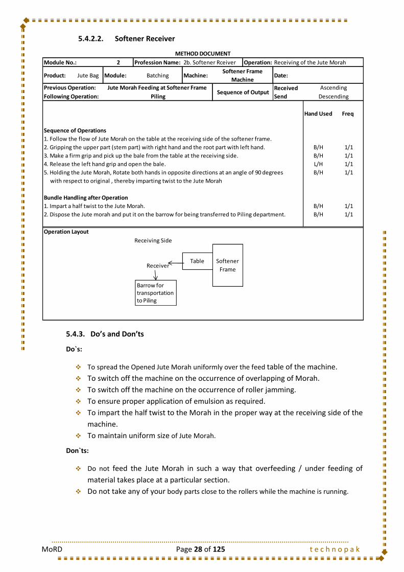
5.4.2.2. Softener Receiver .................................................................................................................. 28
5.4.3. Do’s and Don’ts ......................................................................................................................... 28
5.5. Spreader Frame Operator ............................................................................................................. 29
5.5.1. Machine Details ........................................................................................................................ 29
5.5.2. Method Study ........................................................................................................................... 30
5.5.2.1. Spreader Feeder .................................................................................................................... 30
5.5.2.2. Spreader Receiver ................................................................................................................. 31
5.5.3. Do’s and Don’ts ......................................................................................................................... 31
5.6. Piling Operator .............................................................................................................................. 31
5.6.1. Method Study ........................................................................................................................... 32
5.6.1.1. Piler ....................................................................................................................................... 32
5.6.2. Do’s and Don’ts ......................................................................................................................... 32
5.7. Types of Mazdoor ......................................................................................................................... 33
5.8. Training Gantt Chart ..................................................................................................................... 34
6. MODULE 3: CARDING OF JUTE SLIVER ................................................................................................. 35
6.1. Introduction .................................................................................................................................. 35
6.2. Objective ....................................................................................................................................... 35
6.3. Methodology ................................................................................................................................. 35
6.3.1. Root Cutting (for hard roots) .................................................................................................... 35
6.3.2. Dollop ........................................................................................................................................ 35
6.3.3. Parallelization of Jute Fibre ....................................................................................................... 36
6.4. Breaker Card Frame Operator ...................................................................................................... 36
6.4.1. Machine Details ........................................................................................................................ 36
6.4.2. Method Study ........................................................................................................................... 37
6.4.2.1. Feeder- Hand Feed ................................................................................................................ 37
6.4.2.2. Feeder- Roll Feed .................................................................................................................. 37
6.4.2.3. Receiver................................................................................................................................. 38
6.4.3. Do’s and Don’ts ......................................................................................................................... 38
6.5. Finisher Card Frame Operator ...................................................................................................... 38
6.5.1. Machine Details ........................................................................................................................ 38
6.5.2. Method Study ........................................................................................................................... 39
6.5.2.1. Feeder- Roll Feed .................................................................................................................. 39

MoRD Page 4 of 125 t e c h n o p a k
6.5.2.2. Receiver................................................................................................................................. 40
6.5.3. Do’s and Don’ts ......................................................................................................................... 40
6.6. Types of Mazdoor ......................................................................................................................... 41
6.7. Training Gantt Chart ..................................................................................................................... 41
7. MODULE 4: DRAWING OF JUTE SLIVER ............................................................................................... 42
7.1. Introduction .................................................................................................................................. 42
7.2. Objective ....................................................................................................................................... 42
7.3. Methodology ................................................................................................................................. 42
7.3.1. Attenuation of Jute Sliver ......................................................................................................... 42
7.3.2. Doubling of the Slivers .............................................................................................................. 42
7.4. Drawing Frame Operator .............................................................................................................. 43
7.4.1. Machine Details ........................................................................................................................ 43
7.4.1.1. Mackhigh Push Bar Drawing machine .................................................................................. 43
7.4.1.2. Screw Gill / Spiral Drawing machine ..................................................................................... 43
7.4.2. Method Study ........................................................................................................................... 44
7.4.2.1. Feeder- First Draw Frame ..................................................................................................... 44
7.4.2.2. Receiver & Feeder- Second & Finisher Draw Frame ............................................................. 45
7.4.3. Do’s and Don’ts ......................................................................................................................... 45
7.5. Types of Mazdoor ......................................................................................................................... 46
7.6. Training Gantt Chart ..................................................................................................................... 47
8. MODULE 5: SPINNING OF JUTE SLIVER ................................................................................................ 48
8.1. Introduction .................................................................................................................................. 48
8.2. Objective ....................................................................................................................................... 48
8.3. Methodology ................................................................................................................................. 48
8.3.1. Attenuation of Jute Sliver ......................................................................................................... 48
8.3.2. Twisting of the Sliver ................................................................................................................. 48
8.3.3. Winding of the Yarn .................................................................................................................. 49
8.3.4. Doffing of the Yarn Bobbins ...................................................................................................... 49
8.4. Spinning Frame ............................................................................................................................. 50
8.4.1. Machine Details ........................................................................................................................ 50
8.4.1.1. Machine Types ...................................................................................................................... 50
8.4.1.2. Slip Draft Spinning Frame ..................................................................................................... 50
8.4.1.3. Apron Draft Spinning Frame ................................................................................................. 50
8.4.1.4. Machine Specifications ......................................................................................................... 51
8.4.1.5. Pitch ...................................................................................................................................... 51
8.4.1.6. Lift ......................................................................................................................................... 51

MoRD Page 5 of 125 t e c h n o p a k
8.4.1.7. Spindle R.P.M. ....................................................................................................................... 51
8.4.1.8. Twist Constant ...................................................................................................................... 51
8.4.1.9. Draft Constant ....................................................................................................................... 51
8.4.2. Method Study ........................................................................................................................... 52
8.4.2.1. Spinner .................................................................................................................................. 52
8.4.3. Do’s and Don’ts ......................................................................................................................... 52
8.4.4. Do’s and Don’ts ......................................................................................................................... 54
8.5. Types of Mazdoor ......................................................................................................................... 54
8.6. Training Gantt Chart ..................................................................................................................... 55
9. MODULE 6: WARP WINDING AND TWISTING OF JUTE YARN ............................................................. 56
9.1. Introduction .................................................................................................................................. 56
9.2. Objective of Spool Winding .......................................................................................................... 56
9.3. Methodology ................................................................................................................................. 56
9.4. Spool Winding Frame .................................................................................................................... 57
9.4.1. Machine Details ........................................................................................................................ 57
9.4.2. Method Study ........................................................................................................................... 59
9.4.2.1. Warp Winding Operator ....................................................................................................... 59
9.4.3. Do’s and Don’ts ......................................................................................................................... 59
9.5. Twisting Frame .............................................................................................................................. 61
9.5.1. Machine Details ........................................................................................................................ 61
9.5.2. Method Study ........................................................................................................................... 62
9.5.2.1. Twister .................................................................................................................................. 62
9.5.1. Do’s and Don’ts ......................................................................................................................... 62
9.6. Precision Winding Frame .............................................................................................................. 63
9.6.1. Machine Details ........................................................................................................................ 63
9.6.2. Method Study ........................................................................................................................... 64
9.6.2.1. Precision Winding Operator .................................................................................................. 64
9.6.3. Do’s and Don’ts ......................................................................................................................... 64
9.7. Faults in Winding .......................................................................................................................... 65
9.8. Hard Wastes and its Control ......................................................................................................... 66
9.9. Types of Mazdoor ......................................................................................................................... 67
9.10. Training Gantt Chart ................................................................................................................. 67
10. MODULE 7: COP WINDING OF JUTE YARN ...................................................................................... 68
10.1. Introduction .............................................................................................................................. 68
10.2. Objective ................................................................................................................................... 68
10.3. Dimensions and Yarn Content of Cop ....................................................................................... 68

MoRD Page 6 of 125 t e c h n o p a k
10.4. Methodology ............................................................................................................................. 68
10.5. Cop Winding Frame .................................................................................................................. 69
10.5.1. Machine Details ........................................................................................................................ 69
10.5.2. Method Study ........................................................................................................................... 71
10.5.2.1. Cop Winding Operator .......................................................................................................... 71
10.5.3. Do’s and Don’ts ......................................................................................................................... 71
10.6. Faults in Cop Winding ............................................................................................................... 72
10.7. Hard Wastes and its Control ..................................................................................................... 73
10.8. Productivity: Control Measures ................................................................................................ 73
10.9. Types of Mazdoor ..................................................................................................................... 73
10.10. Training Gantt Chart ................................................................................................................. 74
11. MODULE 8: SIZING AND BEAMING OF JUTE YARN ......................................................................... 75
11.1. Introduction .............................................................................................................................. 75
11.2. Objective ................................................................................................................................... 75
11.3. Methodology ............................................................................................................................. 75
11.3.1. Creeling of yarn bobbins ........................................................................................................... 75
11.3.2. Denting ...................................................................................................................................... 76
11.3.3. Winding the yarn on the beam ................................................................................................. 76
11.3.4. Minimization of yarn fault ........................................................................................................ 76
11.4. Sizing and Beaming Machine .................................................................................................... 76
11.4.1. Machine Details ........................................................................................................................ 76
11.4.2. Method Study ........................................................................................................................... 78
11.4.2.1. Feeder ................................................................................................................................... 78
11.4.2.2. Receiver................................................................................................................................. 79
11.4.3. Do’s and Don’ts ......................................................................................................................... 79
11.5. Waste Control in Sizing and Beaming Machine ........................................................................ 80
11.6. Types of Mazdoor ..................................................................................................................... 80
11.7. Training Gantt Chart ................................................................................................................. 81
12. MODULE 9: WEAVING OF JUTE YARN .............................................................................................. 82
12.1. Introduction .............................................................................................................................. 82
12.2. Objective ................................................................................................................................... 82
12.3. Specification and Quality of Jute fabrics ................................................................................... 83
12.4. Methodology ............................................................................................................................. 84
12.4.1. Primary Motions ....................................................................................................................... 84
12.4.1.1. Shedding ............................................................................................................................... 84
12.4.1.2. Picking ................................................................................................................................... 84

MoRD Page 7 of 125 t e c h n o p a k
12.4.1.3. Beating .................................................................................................................................. 84
12.4.2. Secondary Motions ................................................................................................................... 85
12.4.2.1. Let-Off ................................................................................................................................... 85
12.4.2.2. Take-Up ................................................................................................................................. 85
12.4.3. Auxiliary Motions ...................................................................................................................... 85
12.4.3.1. Warp Protector Motion (fast reed type) ............................................................................... 85
12.4.3.2. Weft Fork .............................................................................................................................. 85
12.4.3.3. Oscillating or Vibrating Backrest ........................................................................................... 85
12.4.3.4. Automatic cop change arrangement or Automatic Cop Loader Motion (Ecco-Loader) ....... 85
12.5. Shuttle Looms ........................................................................................................................... 85
12.5.1. Machine Details ........................................................................................................................ 85
12.5.2. Method Study ........................................................................................................................... 88
12.5.2.1. Weaver .................................................................................................................................. 88
12.5.2.2. Weaving Helper ..................................................................................................................... 89
12.5.3. Do’s and Don’ts ......................................................................................................................... 89
12.6. Production, Efficiency and Quality ............................................................................................ 90
12.6.1. Improvement in production efficiency ..................................................................................... 90
12.6.2. Improvement in quality ............................................................................................................ 91
12.6.3. Reduction of wastage ............................................................................................................... 91
12.6.4. Fabric Faults: Cause and Remedial Measures ........................................................................... 92
12.7. Types of Mazdoor ..................................................................................................................... 94
12.8. Training Gantt Chart ................................................................................................................. 95
13. MODULE 10: FINISHING OF JUTE CLOTH ......................................................................................... 96
13.1. Introduction .............................................................................................................................. 96
13.2. Objective ................................................................................................................................... 97
13.3. Damping Machine ..................................................................................................................... 97
13.3.1. Objective ................................................................................................................................... 97
13.3.2. Machine Details ........................................................................................................................ 97
13.3.2.1. Nozzle Type Damping Machine ............................................................................................. 97
13.3.3. Method Study ........................................................................................................................... 98
13.3.3.1. Feeder- Damping................................................................................................................... 98
13.3.3.2. Receiver- Damping ................................................................................................................ 98
13.3.4. Do’s and Don’ts ......................................................................................................................... 99
13.4. Calendaring Machine ................................................................................................................ 99
13.4.1. Objective ................................................................................................................................... 99
13.4.2. Machine Details ........................................................................................................................ 99

MoRD Page 8 of 125 t e c h n o p a k
13.4.3. Method Study ......................................................................................................................... 100
13.4.3.1. Feeder- Calendaring ............................................................................................................ 100
13.4.3.2. Receiver- Calendaring ......................................................................................................... 101
13.4.4. Do’s and Don’ts ....................................................................................................................... 101
13.5. Lapping Machine ..................................................................................................................... 102
13.5.1. Objective ................................................................................................................................. 102
13.5.2. Machine Details ...................................................................................................................... 102
13.5.3. Method Study ......................................................................................................................... 103
13.5.3.1. Feeder- Lapping .................................................................................................................. 103
13.5.3.2. Receiver- Lapping ................................................................................................................ 104
13.5.4. Do’s and Don’ts ....................................................................................................................... 104
13.6. Cutting Machine ...................................................................................................................... 105
13.6.1. Objective ................................................................................................................................. 105
13.6.2. Machine Details ...................................................................................................................... 105
13.6.3. Method Study ......................................................................................................................... 106
13.6.3.1. Cutting Machine Operator .................................................................................................. 106
13.6.4. Do’s and Don’ts ....................................................................................................................... 106
13.7. Types of Mazdoor ................................................................................................................... 107
13.8. Training Gantt Chart ............................................................................................................... 108
14. MODULE 11: SACK SEWING OF JUTE CLOTH ................................................................................. 109
14.1. Introduction ............................................................................................................................ 109
14.2. Objective ................................................................................................................................. 109
14.3. Sack Sewing Machine .............................................................................................................. 109
14.3.1. Types of Machines .................................................................................................................. 109
14.3.2. Types of Stitch ......................................................................................................................... 110
14.3.3. Types of Seam ......................................................................................................................... 111
14.3.4. Sewing Defects of Jute Bags: Causes and Remedial Measures ............................................... 113
14.3.5. Method Study ......................................................................................................................... 114
14.3.5.1. Hemming Operator ............................................................................................................. 114
14.3.5.2. Herackle Operator............................................................................................................... 115
14.3.5.3. Branding Operator .............................................................................................................. 116
14.3.5.4. Bundler ................................................................................................................................ 117
14.3.6. Do’s and Don’ts ....................................................................................................................... 117
14.4. Types of Mazdoor ................................................................................................................... 118
14.5. Training Gantt Chart ............................................................................................................... 118
15. MODULE 12: PACKING OF JUTE BAG ............................................................................................. 119

MoRD Page 9 of 125 t e c h n o p a k
15.1. Introduction ............................................................................................................................ 119
15.2. Objective ................................................................................................................................. 119
15.3. Methodology ........................................................................................................................... 120
15.4. Baling Press Machine .............................................................................................................. 120
15.4.1. Machine Details ...................................................................................................................... 120
15.4.2. Method Study ......................................................................................................................... 121
15.4.2.1. Press Operator- Bag & Cloth ............................................................................................... 121
15.4.3. Do’s and Don’ts ....................................................................................................................... 121
15.5. Types of Mazdoor ................................................................................................................... 122
15.6. Training Gantt Chart ............................................................................................................... 123
16. MODULE 13: MAZDOOR ................................................................................................................. 124
16.1. Objective ................................................................................................................................. 124
16.2. Types of Mazdoor ................................................................................................................... 124
16.3. Training Gantt Chart ............................................................................................................... 125

MoRD Page 10 of 125 t e c h n o p a k
1. SEJS: An Introduction
The ‘Skills for Employment in Jute Sector’ (SEJS) is a special project under Swaranjayanti Gram
Swarojgar Yojana (SGSY) scheme funded by Ministry of Rural Development (MoRD), Government
of India with the aim of creation of gainful employment in Jute Sector.
Ministry of Rural Development, Government of India has in terms of its letter no J-
17046/93/2009-SGSY-II (SP) dated 16th December 2010 has appointed Technopak for
implementation of this project.
As a part of the SEJS initiative, we plan to train and place ‘Below Poverty Line (BPL)’ youth
belonging to rural areas as workers in Jute Mills. Once training is imparted, these BPL youth will
be provided employment in Jute Mills.
MoRD has appointed NABARD Consulting Services as a Coordinating and Monitoring agency and
Technopak Advisors as an Implementing Partner for this initiative.
MoRD Page 11 of 125 t e c h n o p a k
2. Jute: Introduction
The Jute Textiles Industry occupies an important place in the
Indian economy. It is one of the major industries in the
eastern region, particularly in West Bengal. It supports
nearly 4 million farm families, besides providing direct
employment to about 2.6 Lakh industrial workers and
livelihood to another 1.4 Lakh persons in the tertiary sector
and allied activities. The Jute Industry contributes to the
export earnings to the tune of nearly Rs. 1200 Crores
annually. The production process in the Jute Industry goes
through a variety of activities, which include cultivation of
raw Jute, processing of Jute fibers, spinning, weaving,
bleaching, dyeing, finishing and marketing of both the raw
Jute and its finished products. The Jute Industry is labor
intensive and as such, its labor-output ratio is high in spite of
various difficulties being faced by the industry.
For centuries jute has been an integral part of eastern
regions of the Indian subcontinent. Even today this region is
the single largest producer of raw jute. In the nineteenth and early twentieth century much of
the raw jute produced was exported to the United Kingdom where it was processed. Post 1970s
this stopped due to the popularity of synthetic fibers.
The invention of new end-uses along with the preference for eco-friendly and bio-degradable
products the world over has been an important factor for the increasing demand for Jute
products. Jute has entered many diverse sectors of industry, where natural fibres are gradually
becoming better substitutes. Among these industries are paper, celluloid products (films), non-
woven textiles, composites (pseudo-wood), and Geotextiles.
Cumulative exports of jute goods during 2008-09 stood at Rs. 1066 Crores which is lower by 10%
as compared to 2007-08. This declining trend in cumulative exports in value terms has been
mainly attributable to decline in exports of Hessian by 58%. However, exports of Sacking
increased by 54% and yarn increased by 2% during the same period.
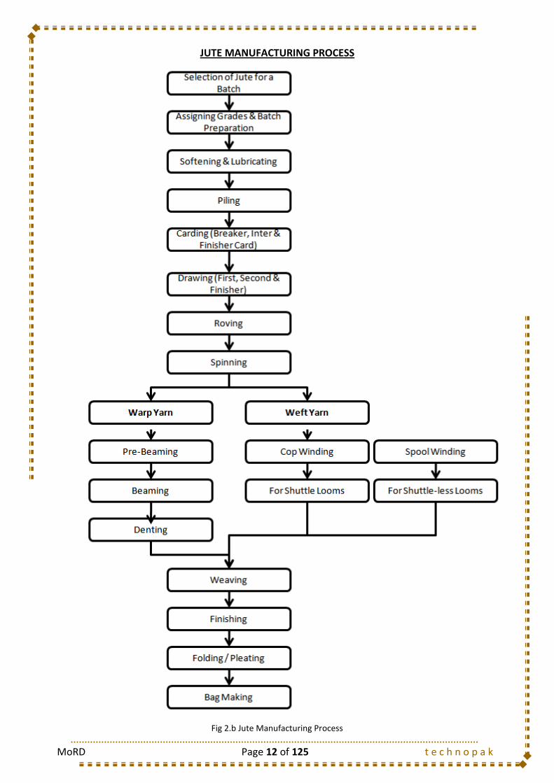
2.1. Jute Manufacturing Process
The steps involved in the Jute manufacturing is indicated through a flowchart shown
below:
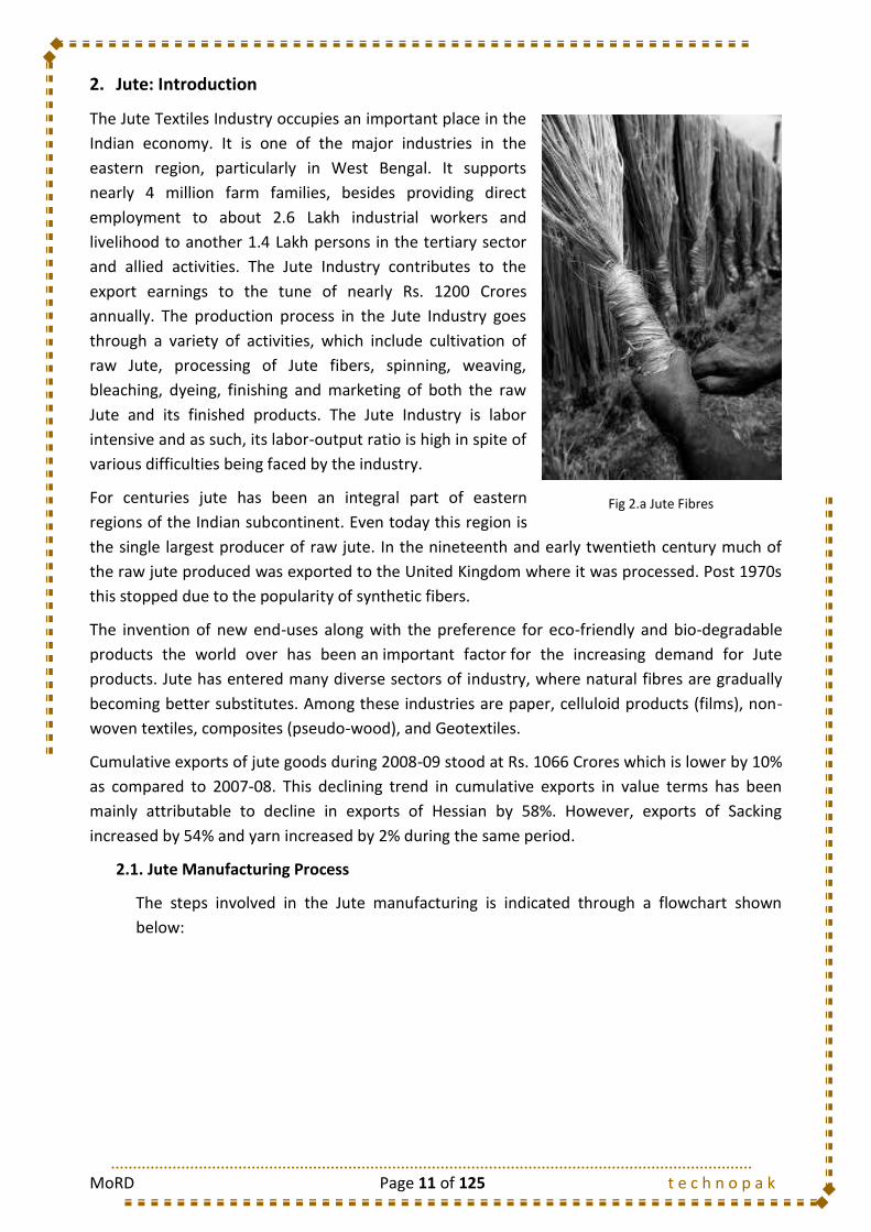
Fig 2.a Jute Fibres
MoRD Page 12 of 125 t e c h n o p a k
JUTE MANUFACTURING PROCESS
Fig 2.b Jute Manufacturing Process
MoRD Page 13 of 125 t e c h n o p a k
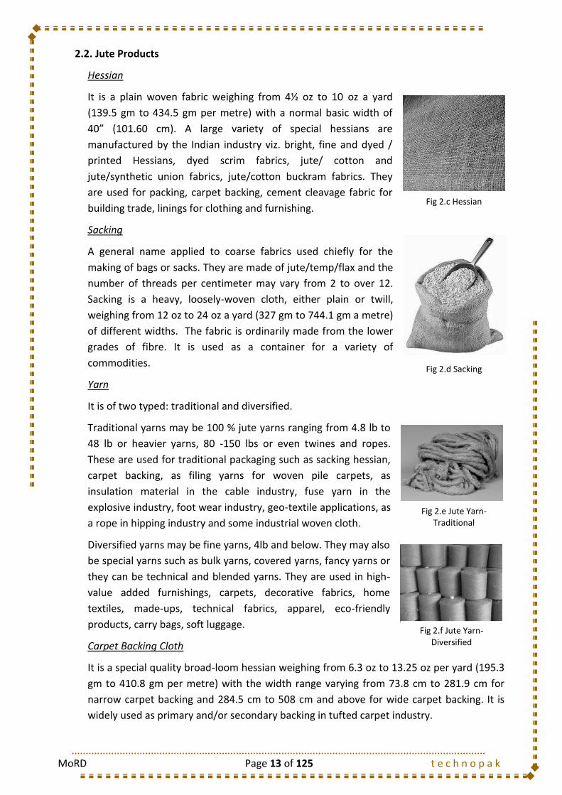
2.2. Jute Products
Hessian
It is a plain woven fabric weighing from 4½ oz to 10 oz a yard
(139.5 gm to 434.5 gm per metre) with a normal basic width of
40” (101.60 cm). A large variety of special hessians are
manufactured by the Indian industry viz. bright, fine and dyed /
printed Hessians, dyed scrim fabrics, jute/ cotton and
jute/synthetic union fabrics, jute/cotton buckram fabrics. They
are used for packing, carpet backing, cement cleavage fabric for
building trade, linings for clothing and furnishing.
Sacking
A general name applied to coarse fabrics used chiefly for the
making of bags or sacks. They are made of jute/temp/flax and the
number of threads per centimeter may vary from 2 to over 12.
Sacking is a heavy, loosely-woven cloth, either plain or twill,
weighing from 12 oz to 24 oz a yard (327 gm to 744.1 gm a metre)
of different widths. The fabric is ordinarily made from the lower
grades of fibre. It is used as a container for a variety of
commodities.
Yarn
It is of two typed: traditional and diversified.
Traditional yarns may be 100 % jute yarns ranging from 4.8 lb to
48 lb or heavier yarns, 80 -150 lbs or even twines and ropes.
These are used for traditional packaging such as sacking hessian,
carpet backing, as filing yarns for woven pile carpets, as
insulation material in the cable industry, fuse yarn in the
explosive industry, foot wear industry, geo-textile applications, as
a rope in hipping industry and some industrial woven cloth.
Diversified yarns may be fine yarns, 4lb and below. They may also
be special yarns such as bulk yarns, covered yarns, fancy yarns or
they can be technical and blended yarns. They are used in high-
value added furnishings, carpets, decorative fabrics, home
textiles, made-ups, technical fabrics, apparel, eco-friendly
products, carry bags, soft luggage.
Carpet Backing Cloth
It is a special quality broad-loom hessian weighing from 6.3 oz to 13.25 oz per yard (195.3
gm to 410.8 gm per metre) with the width range varying from 73.8 cm to 281.9 cm for
narrow carpet backing and 284.5 cm to 508 cm and above for wide carpet backing. It is
widely used as primary and/or secondary backing in tufted carpet industry.
Fig 2.c Hessian
Fig 2.d Sacking
Fig 2.e Jute Yarn- Traditional
Fig 2.f Jute Yarn- Diversified

MoRD Page 14 of 125 t e c h n o p a k
Food Grade Jute Products
It is a hydrocarbon free packaging material. These are odor free and have to abide by
strict international standards. The use of food grade packaging is mandatory for certain
industries like coffee.
Geotextiles
Jute Geo-textiles (JGT) is a kind of natural technical textiles laid in
or on soil to improve its engineering properties. Jute is rick in
cellulose and lignin and is eco friendly.
Lifestyle Products
Jute is also used in lifestyle products such as:
Home and office dressing, door and window curtains and
sofa and cushion covers
Table covers, tea cosy, place mat, napkins for table setting
and tea coasters
Mats, matting, carpets and floor covering
Wall decoration and handicraft items
Shopping and travel bags
Fig 2.g Jute in Geotextiles
Fig 2.h Jute- Lifestyle Products

MoRD Page 15 of 125 t e c h n o p a k
3. Course Matrix
3.1. List of Modules, Professions and their Job Descriptions
Module Department Job Description
1.a Selector Opening the bales. Selection of jute materials as per required quality. Making morah of
desired weight and putting it in barrow/pallette.
1.b Root Cutter Opening the bales. Selection of jute materials as per required quality. Cutting of root,
making morah of desired weight and putting it in barrow/pallette.
2.a Softener Feeder Taking the morahs from the pallete/barrow, spreading the same over the feed table of
the softener machine.
2.b Softener Receiver Receiving of the morahs coming out from the machine at the other end, Making of the
morah and putting it on the pallette/barrow.
2.c Softener Piler To collect the material from the receiving end of the softener machine, Making a pile.
2.d Spreader Feeder Taking the morahs from the pallete/barrow, spreading the same over the feed table of
the spreader machine.
2.e Spreader Receiver-cum-Piller Receiving of the rolls coming out from the machine at the other end and putting it in the
piles.
1.c Root Cutter (Only for Hand Feed Card) Taking the morah from the pallette, cutting the roots and again putting the morahs at the
feed end of the card.
3.a Feeder - Hand Feed Feeding of morahs over the feed table by spreading them uniformly and at regular
interval.
3.b Feeder - Roll Feed To carry the roll from the pile position and feeding them into the card.
3.c Receiver Putting the sliver from the drawing roller to the pressing roller. Collecting the rolls from
the roll former and feeding them into the next card.
4.a Feeder (Types- Rotary/Screw Driving Gill-bars) Collection of rolls from the finisher card/sliver cans from drawing stage, and feeding
them into the next drawing.
4.b Receiver (Types- Rotary/Screw Driving Gill-bars) Receiving the cans from the earlier drawing.
5.a Spinner
(Types- Slip Draft, Apron Draft )
Passing the sliver from retaining roller and taking the yarn till bobbin. Piece-up the yarn
in case of any breakages. Doff the bobbin.
5.b Bobbin Carrier Replace the filled bobbin with the empty bobbin and carry the bobbins to the winding
area.
6.a Warp Winding Operator Put the bobbin on the spindle, piecing the yarn, taking the yarn upto empty
cone/cheese, starting the cone, doffing of the cones after finishing.
6.c Precision Winding Operator (Export Yarns) Put the bobbin/first winding spool on the spindle, pieceing the yarn, taking the yarn
upto the spool, doff the spool.
6.c Twister Take the spools from the side of the machine and put it on the creel. Passing the yarn
from drawing roller to the bobbin/pirn. Piece-up the yarn in case of any breakages. Doff
the bobbin. Carry the finished bobbin upto the precision winding place.
7 Cop Winding 7.a Cop Winding Operator
(Types- Manual & Semi-automatic)
Put the bobbin on the spindle, piecing the yarn, taking the yarn upto cop, starting the
spindle, doffing of the cops and making bundles after finishing.
8.a Feeder (both) Take the spools/beam from the side of the machine and put it on the creel. Pass it to the
warp beam.
8.b Receiver (both) Piece-up the yarn. Start & stop the machine and doff the warp beam.
9.a Weaver
(Types: Manual, Semi-automatic & Shuttleless)
Piece-up the yarn in case of breakages. Loading the shuttle. Start & stop the machine.
Doffing of finishined cloth roll.
9.b Helper Bring the cop bundles and put near the loom. Loading the beam on the loom. Denting,
reeding and wrap it till the cloth beam. Relieving the weaver.
10.a Feeder - Damping Feeding the cloth, controlling the water flow to maintain required moisture level
10.b Receiver - Damping Receiving the cloth, controlling the water flow to maintain required moisture level and
handing over the material for the next process. Segregate defective cloth by visual
inspection.
10.c Feeder - Calendar Feeding the cloth continuously
10.d Receiver - Calendar Receiving the cloth continously and handing over the material for next process.
Segregate defective cloth by visual inspection.
10.e Feeder - Lapping Feeding the cloth
10.f Receiver - Lapping Receiving the cloth
10.g Cutting Machine Operator Feeding & receiving the cloth. Segregate defective cloth by visual inspection.
11.a Hemming Operator Folding as per specifications and Stitching
11.b Herakel Operator Folding as per specifications and Stitching bags
11.c Branding Operator Screen printing
11.d Bundler Counting the number as per specifications, making bundles by stitching and knotting
12 Packing 12.a Press Operator - Bag & Cloth Placing the baling hoops & pack sheet on the ram of the press, then putting the required
number of bundles/cloth over the pack sheet. Performing the pressing operation,
stitching the pack sheet from all sides, locking the baling hoops, releasing the pressure
and removing the pack bales from the press.
13 Mazdoor 13.a All categories of Mazdoors Mostly carrying of materials from one place to another i.e. from one machine to another.
This includes :Jute Bale carrying Mazdoor : bringing of Jute bales from the mokam to the
mill.Spinning Bobbin Carrying Mazdoor : Carrying of bobbins from winding department
to spinning department and vice versa.
Profession
1 Selection
2 Batching
3 Carding
(Breaker, Inter & Finisher)
4 Drawing
(First, Second & Finisher
Passage)
5 Spinning
6 Warp Winding & Twisting
11 Sack-Sewing
8 Sizing & Beaming
9 Weaving
10 Finishing

MoRD Page 16 of 125 t e c h n o p a k
4. MODULE 1: SELECTION OF JUTE FIBRE
4.1. Introduction
Jute is a lingo-cellulosic, multi cellular bast fiber obtained from the plant body or stalk of
Jute plant. There are two important commercial varieties of jute, namely white jute and
Tossa jute. Another type of fiber, similar to jute but of different botanical origin, is widely
used in the jute industry which is known as Mesta. Mesta fiber is coarser in nature than
jute, but is processed similarly to jute and in mixing with jute. So, Mesta is not dealt here
separately, as everything discussed for coarser jute is equally applicable for mesta fiber.
4.2. Jute Fibre: Different Types
Jute that is grown in India is classified in four varieties or categories:
Tossa
White
Mesta
Bimli
Based on the grading, each one is further classified on a scale of 1 to 8 (where 1 is the best
grade and 8 is the worst). The classification is done for Tossa as TD1, TD2 . . . TD8 or for
White as WD1 . . . WD8. The highest production is that of Tossa fibre which accounts for
nearly 78%, followed by White which is 10%.
4.2.1. Different Grades and their Properties
In India with object of enabling the cultivators to get proper price for their fiber, Bureau of
Indian Standards (BIS) introduced a standard for grading of raw jute on the basis of its
quality. Both White and Tossa jute fibers are classified into eight grades, W1-W8, and TD1-
TD8. Each grade is assessed by scoring six characters - strength, fineness, defects, root
contents, colour and density.
The various properties of different grades of White and Tossa types of Jute Fibers are
shown as below:
Grade Properties
W1/TD1 Very good strength and colour, very fine heavy bodied fibre, free from major and minor defects. Maximum root content: W1-10%, TD1-5%.
W2/TD2 Good strength and colour, fine heavy bodied fibre, free from major and minor defects. Maximum root content: W2-15%, TD2-10%.
W3/TD3 Fairly good colour and strength well separated medium bodied fibre, free from major and minor defects except a few specks. Maximum root content: W3-20%, TD3-15%.
W4/TD4 Fair, average strength and colour, well separated medium bodied fibre, free from major defects and substantially free from specks and loose sticks. Maximum root content: W4-26 % , TD4-20 % .
W5/TD5 Average strength and colour, fine from major defects. Maximum root content: W5-36%, TD5-26%.
W6/TD6 Average strength, free from centre root and dazed/over-retted fibre and reasonably free from entangled sticks. Maximum root content: W6-46%, TD6 - 35%.
MoRD Page 17 of 125 t e c h n o p a k
Grade Properties
W7/TD7 Weak mixed fibre with maximum root content: W7-57%. TD7-35%.
W8/TD8 Entangled or any other jute not suitable for any of the above grade but of commercial value.
4.2.2. Basis of Grading
The main factors which differs one grade of Jute fibre fiber from the other are:
Quality varies from place to place and season to season
Topography
Nature of Soil and Water
Rainfall
Humidity
Practices followed in Growing
Methods used in retting extraction of fiber
Washing
Drying
Storage
The various parameters based on which the Grading is normally done are:
Length
Strength
Colour
Lustre
Weight
General qualities like softness, smoothness, distinctness and uniformity of the
fibre
Proportion of cuttings, hard-centered fiber and harsh crop ends
Proportion of faults such as roots, bark, sticks, specks, knots, runners and
watermarks
4.2.3. Grading by Kutcha Balers
Jute fibre after extraction is graded by Kutcha Balers as:
Top Very Strong Fibers
Middle Strong Fiber and Average color and luster
Bottom Sound Fiber, medium strength, not suitable for higher grades
C-Bottom Medium strength fibre, any colour
X-Bottom (Cross Bottom) Weak hard jute
4.2.4. Quality Parameters
The Quality Parameters on which grading is normally practiced in Jute Industry are:
Strength
Root Content
Defects
MoRD Page 18 of 125 t e c h n o p a k
Colour
Fineness
Bulk-Density
4.3. Objective
The main objectives of Selection of Jute are:
To select the different grades of jute for different product`s quality
To separate the root portion from the reed
To make the Jute ready for the softening department
To prepare the Jute Morah of required weight
4.4. Methodology
4.5. Quality Assessment by Hand and Eye Method (Visual Inspection)
The quality of jute fibre is judged by its suitability for the production of various types of
yarn and its behaviour in the manufacturing process. The fibre which spins into the finest
yarn is considered to be of very good quality.
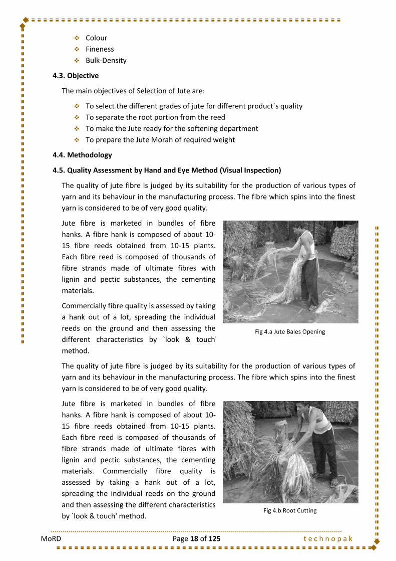
Jute fibre is marketed in bundles of fibre
hanks. A fibre hank is composed of about 10-
15 fibre reeds obtained from 10-15 plants.
Each fibre reed is composed of thousands of
fibre strands made of ultimate fibres with
lignin and pectic substances, the cementing
materials.
Commercially fibre quality is assessed by taking
a hank out of a lot, spreading the individual
reeds on the ground and then assessing the
different characteristics by `look & touch'
method.
The quality of jute fibre is judged by its suitability for the production of various types of
yarn and its behaviour in the manufacturing process. The fibre which spins into the finest
yarn is considered to be of very good quality.
Jute fibre is marketed in bundles of fibre
hanks. A fibre hank is composed of about 10-
15 fibre reeds obtained from 10-15 plants.
Each fibre reed is composed of thousands of
fibre strands made of ultimate fibres with
lignin and pectic substances, the cementing
materials. Commercially fibre quality is
assessed by taking a hank out of a lot,
spreading the individual reeds on the ground
and then assessing the different characteristics
by `look & touch' method.
Fig 4.a Jute Bales Opening
Fig 4.b Root Cutting

MoRD Page 19 of 125 t e c h n o p a k
Fibre Selection and Characteristics
During bulk selection of Jute reed from bales by selector in mill floor, the hand and eye
assessment and the subsequent grading of jute on that basis as well as upgradation and
down gradation, morah weight distribution etc. are to be done promptly and quickly.
Hand may feel fineness, bulk density and strength while eye will judge colour, root
content and defects of the fibre which are described as below:
4.5.1. Strength
To assess the strength of jute fibre by hand,
a bundle of 15-20 clean individual jute fibre
from the middle region of the fibre bulk is
gripped about 5 cm (2 inch) apart between
thumb and forefingers using both the hands
and is attempted to break the fibre bundle
slowly without any jerk. The way it breaks
and the type of sound heard gives an idea
about the fibre strength on feeling by hand
and ear.
4.5.2. Root Content
An estimate of percentage of root content by weight should be done. However, this may
be done by a visual assessment of root content observing approximately the length
percentage of root in jute reed and multiplying the value by two to get an idea of weight
percentage of root content.
4.5.3. Defects
There are 12 types of defects in jute fibre which are grouped as major and minor defects
as mentioned below:
Major Defects Minor Defects
1. Knot (stiff barky spot) 1. Gummy fibre (Gummy pectinous matters)
2. Runner (Long hard barky fibres) 2. Specks (Soft barky and week spots)
3. Dazed fibre (Very weak, dull and easily powdered)
3. Loose leaf (Dark grey leaf remnants)
4. Over-retted fibre (lost strength and colour) 4. Loose sticks (Broken loose sticks adhered)
5. Centre Root (Bukchhal or hard barky root in the middle)
5. Croppy end (Rough and hard top end)
6. Mossy Fibre (Mossy matters gets attached) 6. Natural Dust (Adhered dirt and dust)
7. Entangled sticks (Broken entangled stick still adhered)
8. Hunka (Remnant woody parts)
Fig 4.c Checking Fibre Strength

MoRD Page 20 of 125 t e c h n o p a k
4.5.4. Colour
Jute fibres are obtained in varying colours from creamy white/creamy yellow to brownish
grey/reddish yellow or white. Different colour groups have also been defined in B.I.S
Specifications as follows:
Term White Jute Tossa Jute Daisee Jute
Very Good
Light Creamy to White Golden to Reddish white Reddish
Good Creamy pink to Brownish
white Reddish to brownish
white Reddish to brownish with
some light grey
Fairly Good
Brownish to Reddish white with some light grey
Reddish or Brownish with some light grey
Brownish or light grey with some grey
Fairly Average
Brownish to Light grey Light grey to copper
colour Light grey
Average Grey to Dark grey Grey to dark grey Grey to dark grey
4.5.5. Fineness
Fibre Fineness is inversely proportional to the diameter of the filament. It can be
estimated simply by opening the mesh-like structure and examining the filament by a
close look at it. White Jute is finer than Tossa Jute. During visual assessment of fineness,
the extent of separation of jute fibers is also looked into.
4.5.6. Bulk Density
The bulk density of jute fibre is judged by the feel of heaviness or lightness of a few jute
reeds from the middle region of fibre bulk, by holding tightly within a grip between two
hands. The lightness/heaviness of gripped Jute fibres in hands is felt by moving hands up
and down.
Croppy Dazed Hanka Loose Leaf Runner Specks
Fig 4.d Jute Fibre Defects
MoRD Page 21 of 125 t e c h n o p a k
4.6. Method Study
4.6.1. Selector
1 Profession Name: Operation:
Product: Jute Bag Module: Selection Machine: Date:
Received
Send
Bale Handling before Operation Hand Used Freq
1. Unload the Jute Bale from the truck with both the hands B/H 1/1
Sequence of Operations
1. Gripping the upper part (stem part) with right hand and the root part with left hand B/H 1/1
2. Make a firm grip and pick up the bale. B/H 1/1
3. Release the left hand grip and open the bale. L/H 1/1
4. Spread the Jute bale on the floor holding the stem part of the bale with right hand. B/H 1/1
5. Look at the overall Spreaded Jute Bale carefully.
Bundle Handling after Operation
1. Impart a half twist to the Jute Morah. B/H 1/1
2. Dispose the Jute morah and put it on the barrow for being transferred to Batching department. B/H 1/1
Operation Layout
Following Operation:Sequence of Output
None
Jute Morah Feeding at Softener Frame Descending
Ascending
METHOD DOCUMENT
NA
1a. SelectorModule No.: Selection of the Jute Bale
Previous Operation:
Area for Spreading
Jute Morah Barrow
Jute Bale Barrow
Selector
MoRD Page 22 of 125 t e c h n o p a k
4.6.2. Root Cutter
4.7. Do’s and Don’ts
The checking of grades of jute i.e selection of jute by mill workers/selectors to check or to
investigate the fibre quality parameters of baled jute fibre strand by selector`s hand and
eye estimation to judge its real quality and then to declare it as right or downgraded or
upgraded. The following points a jute selector must follow as Do`s and Don`ts:
Bring the bales from godown to the selection spot or any other place using the
specified material handling equipments, keeping its mark (for mokam declared
grade) in right position.
Transport the specified number of bales of selected qualities from one place to
another as per the instructor of the sardar/supervisor.
Weigh the bales if necessary as per supervisor`s instructions.
Remove the bale ropes/hoop irons using the specified tool, cut them(in case of
ropes)/loose the hoop irons without cutting the hoop irons from the bales and
dispose them at the specified place as per Sardar`s/Supervisor`s instructions.
Collect the Bale mark (marka) and keep them at the specified place.
1 Profession Name: Operation:
Product: Jute Bag Module: Selection Machine: Date:
Received
Send
Bale Handling before Operation Hand Used Freq
1. Unload the Jute Bale from the truck with both the hands B/H 1/1
Sequence of Operations
1. Gripping the upper part (stem part) with right hand and the root part with left hand B/H 1/1
2. Make a firm grip and pick up the bale. B/H 1/1
3. Release the left hand grip and open the bale. L/H
4. Spread the Jute bale on the floor holding the stem part of the bale with right hand. B/H 1/1
5. Look at the overall Spreaded Jute Bale carefully.
6. Gripping the Jute Bale just above the root portion with right hand. R/H 1/1
7. Changing the grip to left hand. B/H 1/1
8. Cut the root portion of the Jute Bale, gripping the bale with left hand, and cutting the bale B/H 1/1
with right hand by means of a Cutter.
Bundle Handling after Operation
1. Impart a half twist to the Jute Morah. B/H 1/1
2. Dispose the Jute morah and put it on the barrow for being transferred to Batching department. B/H 1/1
Operation Layout
METHOD DOCUMENT
Module No.: 1b. Root Cutter Root Cutting of the Jute Bale
NA
Previous Operation: NoneSequence of Output
Ascending
Following Operation: Jute Morah Feeding at Spreader Frame Descending
Area for Spreading
JuteMorah
Jute Bale Barrow
Selector
Cutter

MoRD Page 23 of 125 t e c h n o p a k
Selection of jute fibre should judiciously be done following the importance of
quality parameters discussed in the section “Grading of Jute”. Accordingly,
upgrade and downgrade jute fibre properly. During upgrading or downgrading of
jute fibre of jute fibre follow each instruction given by sardar/supervisor and the
section “Grading of Jute”
After proper selection of jute fibre strands (handful of reed taken each time by a
selector), the strand should be half twisted and folded at the middle to prepare a
morah of jute fibres of desired weight uniformly. Morah should be prepared in
correct way.
Morah weight should be around 2-2.5 lbs. (1-1.2 kg) and morah weight should be
uniform as far as possible.
Pre-determined batch mixing of Jute fibre for preparing a particular yarn should be
strictly followed. Hence, do not mix up one quality of jute with other.
Bales of particular batch if not found suitable or good, it should immediately be
brought to the knowledge of supervisor/In-charge.
Selected morahs should be conveniently arranged to the Softener/Spreader feed
end.
Barrows with selected morah should be marked with proper identification mark, to
avoid mixing up of one quality of jute fibre with other.
Ropes and habijabi should be collected at one place for further processing and to
be kept at predetermined fixed place.
4.8. Types of Mazdoor
S. No. Mazdoor Type Job Description
1 Jute Bale Unloading Mazdoor
Unloading of the Jute Bales from the truck
2 Jute Bale Handling Mazdoor
Stacks the Jute Bales in the Barrow sequentially

MoRD Page 24 of 125 t e c h n o p a k
4.9. Training Gantt Chart
Training Days Required
Class Room Training Shop Floor Training
3 Days 3 Days
1 2 3
4.1
4.1.1
4.1.2
4.1.2.1 Different Grades and their Properties
4.1.2.2 Basis of Grading
4.1.2.3 Grading by Kutcha Balers
4.1.2.4 Quality Parameters
4.2
4.3
4.3.1
4.4
4.4.1 Selector
4.4.2 Root Cutter
4.5
4.6
1 2 3
4.1
4.1.1
4.1.2
4.1.2.1 Different Grades and their Properties
4.1.2.2 Basis of Grading
4.1.2.3 Grading by Kutcha Balers
4.1.2.4 Quality Parameters
4.2
4.3
4.3.1
4.4
4.4.1 Selector
4.4.2 Root Cutter
4.5
4.6
Introduction
Jute Fibre : Different Types
I. CLASSROOM TRAINING
Quality Assessment by Hand and Eye Method
Jute Fibre : Different Types
MODULE 1 : SELECTION
Jute Fibre : Grading
Objective
Method Study
Do`s and Don`ts
Types of Mazdoor
Introduction
Mazdoor Activities
Quality Assessment by Hand and Eye Method
Method Study
Do`s and Don`ts
II. SHOP-FLOOR TRAINING
Jute Fibre : Grading
Objective
Methodology
Methodology

MoRD Page 25 of 125 t e c h n o p a k
5. MODULE 2: BATCHING OF JUTE FIBRE
5.1. Introduction
Jute is basically stiff and harsh fibre and in consequence it does not possess good spinning
properties. Raw jute fibres if carded and spun in its natural state, without any oil in water
emulsion, there will be heavy short fibre generation during spinning preparatory
processing, and the resultant yarn will be hairy as well as of poor quality. To process jute
fibre successfully with minimum waste, it requires to be softened (i.e. it must be made
pliable) with nearly 15-25% additional water (where water content of jute goes upto 35-
40% including its inherent moisture) as well as to be oiled in a limited extent (1.5-3%). Oil
reduces the fibre-metal friction; reduces the evaporation of water and increases fibre to
fibre friction for control attenuation.
The machinery used for the purpose is either Jute Spreader or Jute Softener machine. Jute
softener is mostly used but in case of finer or better quality yarns, Jute spreader machine
is used. For spreader machine, roots must be cut during selection stage. In both the
machines, Oil and water emulsion is to be applied in correct proportion on jute fibre while
passing through these machines.
5.2. Objective
The main Objectives of the process of Batching are:
To crush the hard materials attached to the jute fiber.
To remove the loose undesirable materials, dust and dirt present in the Jute
Morah.
To lubricate the Jute fiber and soften the fiber.
5.3. Methodology
5.3.1. Emulsion Application
Emulsion is an intimate mixture of oil and water with the aid of an emulsifier. It usually
contains suitable batching oil, water and an emulsifying agent. Its purpose is to make the
fiber pliable and flexible and thereby improve its spinning ability.
The water (approximately 35%) actually softens and makes the fiber pliable and the oil
(approximately 1.5-3%) prevents the evaporation of the absorbed water from fiber. The
oil also acts as a lubricating agent for reducing friction between fiber and machine parts.
Oil also increases inter friction, putting some extent of resistance during drafting.
The vital aspects of emulsion application of jute are :
Uniformity of Application
Method of Application
Amount of Application
Quality of Emulsion Application
Emulsion amount critically depends on the atmospheric conditions (like humidity,
temperature etc.).
MoRD Page 26 of 125 t e c h n o p a k
5.3.2. Softening and Lubrication of Jute Fibre
The impregnation of the emulsion into the Jute fiber happens after a considerable amount
of time. After the application of emulsion, the Jute fiber is kept for some time so that the
emulsion gets time to penetrate into the Jute fiber and thus pliability of the fiber take
improves. The process of Batching mainly involves the removal of impurities from the Jute
fiber. When the Jute Fiber passes through the rollers, any hard materials or impurities
attached to it gets crushed, thereby softening the fiber. Moreover, the application of Oil-
in-water emulsion lubricates the jute fiber and makes it eligible for processing in the later
stages.
5.4. Softener Frame Operator
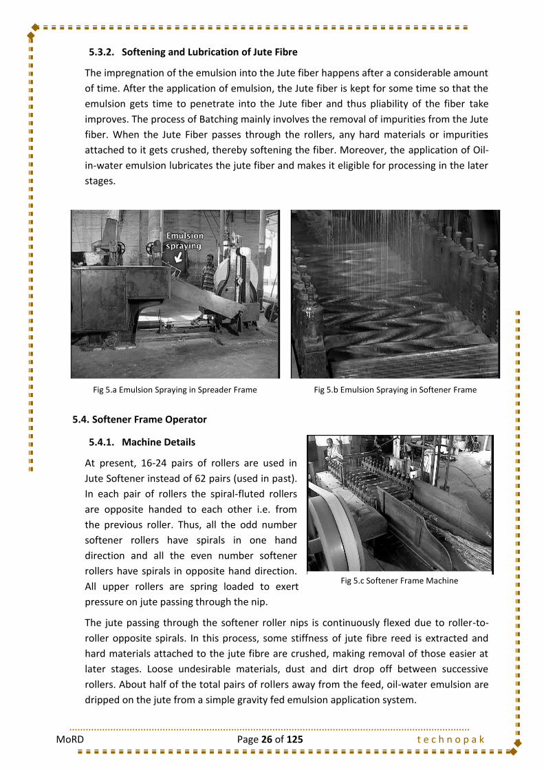
5.4.1. Machine Details
At present, 16-24 pairs of rollers are used in
Jute Softener instead of 62 pairs (used in past).
In each pair of rollers the spiral-fluted rollers
are opposite handed to each other i.e. from
the previous roller. Thus, all the odd number
softener rollers have spirals in one hand
direction and all the even number softener
rollers have spirals in opposite hand direction.
All upper rollers are spring loaded to exert
pressure on jute passing through the nip.
The jute passing through the softener roller nips is continuously flexed due to roller-to-
roller opposite spirals. In this process, some stiffness of jute fibre reed is extracted and
hard materials attached to the jute fibre are crushed, making removal of those easier at
later stages. Loose undesirable materials, dust and dirt drop off between successive
rollers. About half of the total pairs of rollers away from the feed, oil-water emulsion are
dripped on the jute from a simple gravity fed emulsion application system.
Fig 5.a Emulsion Spraying in Spreader Frame Fig 5.b Emulsion Spraying in Softener Frame
Fig 5.c Softener Frame Machine

MoRD Page 27 of 125 t e c h n o p a k
Feeding operator must feed the crop end of the morahs first, and spread the root all over
the width of the feed sheet.
Thus, the root ends get the maximum amount of emulsion, which is mostly needed for
softening. The operator at the receiving end collects the processed morahs and gives it a
half twist at the mid-length for easy handling at subsequent stages and to prevent
undesirable tangling. The morahs are placed on a table or in a barrow, in a neat and
orderly manner with identification mark of quality of jute.
5.4.2. Method Study
5.4.2.1. Softener Feeder
2 Profession Name: Operation:
Product: Jute Bag Module: Batching Machine: Date:
Received
Send
Hand Used Freq
Sequence of Operations
1. Gripping the upper part (stem part) with right hand and the root part with left hand B/H 1/1
2. Make a firm grip and pick up the bale from the barrow. B/H 1/1
3. Release the left hand grip and open the bale. L/H 1/1
4. Spread the Jute bale over the feed table of the softener frame evenly holding the stem part B/H 1/1
of the bale with left hand.
5. Spread the Jute fibers evenly over the feed table of the softener frame. B/H 1/1
Operation Layout
METHOD DOCUMENT
Module No.: 2a. Softener Feeder Feeding of the Jute Morah
Softener Frame
Machine
FeederJute
Morah Feed Table
Previous Operation: Selection Ascending
Following Operation: Jute Morah Receiving
Jute Card
Frame
DescendingSequence of Output
MoRD Page 28 of 125 t e c h n o p a k
5.4.2.2. Softener Receiver
5.4.3. Do’s and Don’ts
Do`s:
To spread the Opened Jute Morah uniformly over the feed table of the machine.
To switch off the machine on the occurrence of overlapping of Morah.
To switch off the machine on the occurrence of roller jamming.
To ensure proper application of emulsion as required.
To impart the half twist to the Morah in the proper way at the receiving side of the
machine.
To maintain uniform size of Jute Morah.
Don`ts:
Do not feed the Jute Morah in such a way that overfeeding / under feeding of
material takes place at a particular section.
Do not take any of your body parts close to the rollers while the machine is running.
2 Profession Name: Operation:
Product: Jute Bag Module: Batching Machine: Date:
Received
Send
Hand Used Freq
Sequence of Operations
1. Follow the flow of Jute Morah on the table at the receiving side of the softener frame.
2. Gripping the upper part (stem part) with right hand and the root part with left hand. B/H 1/1
3. Make a firm grip and pick up the bale from the table at the receiving side. B/H 1/1
4. Release the left hand grip and open the bale. L/H 1/1
5. Holding the Jute Morah, Rotate both hands in opposite directions at an angle of 90 degrees B/H 1/1
Bundle Handling after Operation
1. Impart a half twist to the Jute Morah. B/H 1/1
2. Dispose the Jute morah and put it on the barrow for being transferred to Piling department. B/H 1/1
Operation Layout
Receiving Side
Receiver
with respect to original , thereby imparting twist to the Jute Morah
Softener
Frame
Table
Previous Operation: Jute Morah Feeding at Softener Frame Sequence of Output
Ascending
Following Operation: Piling Descending
METHOD DOCUMENT
Module No.: 2b. Softener Rceiver Receiving of the Jute Morah
Softener Frame
Machine
Barrow for transportation to Piling

MoRD Page 29 of 125 t e c h n o p a k
5.5. Spreader Frame Operator
5.5.1. Machine Details
The Spreader machine basically consists of
two endless chains carrying heavy coarser
pins. One chain is running faster than the
other. The root cut morahs of jute reed
prepared during selection are laid one by one
by hand on the feed sheet of the spreader, in
such a way so that the root end of one morah
must be overlapping with the crop end of
previous morah. This is the point where the
separate and individual reeds of jute are
assembled into a continuous sliver form. The
morahs of jute pass between a pair of fluted rollers and then on to the pins of slow
moving chain (pinned) lattice known as “slow chain”. Above the “slow chain” there are
three lantern rollers to press the jute firmly down the pins. Half-way along the machine
the material is transferred from the pins of slow chains to those of a similar chain having a
higher surface speed which is known as “fast chains”. Due to this difference in the chain
speeds, the jute fibres are teased and combed at the transfer point of spreader machine.
The jute reed comes of the fast chain, passes between a pair of fluted delivery rollers and
is guided down to an open-top channel where controlled amount of oil in water emulsion
is added by a pressure spray. Finally, the sliver is collected in roll form by a pneumatic roll
former at the delivery end of the spreader.
Fig 5.d Spreader Frame Machine

MoRD Page 30 of 125 t e c h n o p a k
5.5.2. Method Study
5.5.2.1. Spreader Feeder
2 Profession Name: Operation:
Product: Jute Bag Module: Batching Machine: Date:
Received
Send
Hand Used Freq
Sequence of Operations
1. Gripping the upper part (stem part) with right hand and the root part with left hand B/H 1/1
2. Make a firm grip and pick up the bale from the barrow. B/H 1/1
3. Release the left hand grip and open the bale. L/H 1/1
4. Spread the Jute bale over the feed table of the spreader frame evenly holding the B/H 1/1
stem part of the bale with left hand.
5. Spread the Jute fibers evenly over the feed table of the spreader frame. B/H 1/1
Operation Layout
Jute
Spreader
Frame
Feed Table
Previous Operation: SelectionSequence of Output
Ascending
Following Operation: Jute Sliver Rolls Receiving Descending
METHOD DOCUMENT
Module No.: 2d. Spreader Feeder Feeding of the Jute Morah
Spreader Frame
Machine
FeederJute Morah Barrow
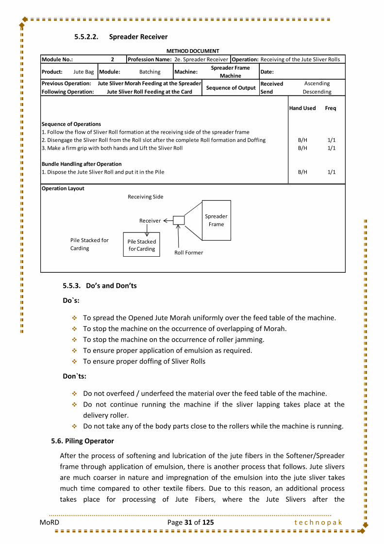
MoRD Page 31 of 125 t e c h n o p a k
5.5.2.2. Spreader Receiver
5.5.3. Do’s and Don’ts
Do`s:
To spread the Opened Jute Morah uniformly over the feed table of the machine.
To stop the machine on the occurrence of overlapping of Morah.
To stop the machine on the occurrence of roller jamming.
To ensure proper application of emulsion as required.
To ensure proper doffing of Sliver Rolls
Don`ts:
Do not overfeed / underfeed the material over the feed table of the machine.
Do not continue running the machine if the sliver lapping takes place at the
delivery roller.
Do not take any of the body parts close to the rollers while the machine is running.
5.6. Piling Operator
After the process of softening and lubrication of the jute fibers in the Softener/Spreader
frame through application of emulsion, there is another process that follows. Jute slivers
are much coarser in nature and impregnation of the emulsion into the jute sliver takes
much time compared to other textile fibers. Due to this reason, an additional process
takes place for processing of Jute Fibers, where the Jute Slivers after the
2 Profession Name: Operation:
Product: Jute Bag Module: Batching Machine: Date:
Received
Send
Hand Used Freq
Sequence of Operations
1. Follow the flow of Sliver Roll formation at the receiving side of the spreader frame
2. Disengage the Sliver Roll from the Roll slot after the complete Roll formation and Doffing B/H 1/1
3. Make a firm grip with both hands and Lift the Sliver Roll B/H 1/1
Bundle Handling after Operation
1. Dispose the Jute Sliver Roll and put it in the Pile B/H 1/1
Operation Layout
Receiving Side
Receiver
Roll Former
Spreader
Frame
Pile Stacked for
Carding
Previous Operation: Jute Sliver Morah Feeding at the Spreader Sequence of Output
Ascending
Following Operation: Jute Sliver Roll Feeding at the Card Descending
METHOD DOCUMENT
Module No.: 2e. Spreader Receiver Receiving of the Jute Sliver Rolls
Spreader Frame
Machine
Pile Stacked for Carding
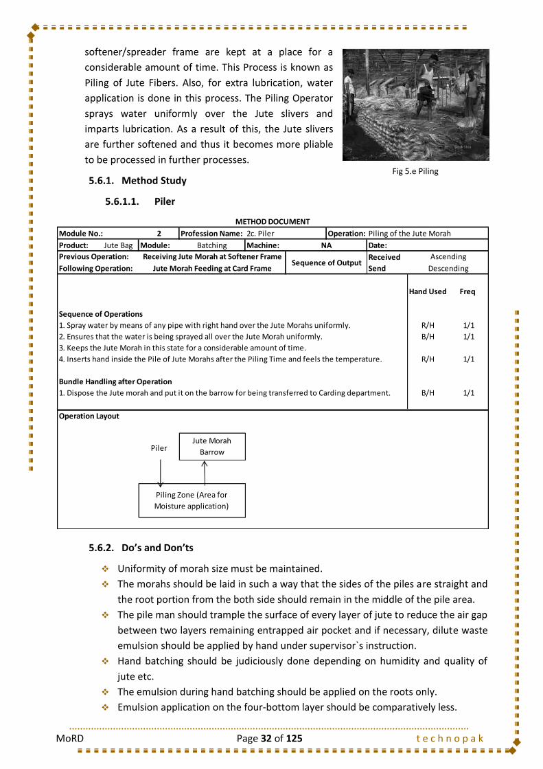
MoRD Page 32 of 125 t e c h n o p a k
softener/spreader frame are kept at a place for a
considerable amount of time. This Process is known as
Piling of Jute Fibers. Also, for extra lubrication, water
application is done in this process. The Piling Operator
sprays water uniformly over the Jute slivers and
imparts lubrication. As a result of this, the Jute slivers
are further softened and thus it becomes more pliable
to be processed in further processes.
5.6.1. Method Study
5.6.1.1. Piler
5.6.2. Do’s and Don’ts
Uniformity of morah size must be maintained.
The morahs should be laid in such a way that the sides of the piles are straight and
the root portion from the both side should remain in the middle of the pile area.
The pile man should trample the surface of every layer of jute to reduce the air gap
between two layers remaining entrapped air pocket and if necessary, dilute waste
emulsion should be applied by hand under supervisor`s instruction.
Hand batching should be judiciously done depending on humidity and quality of
jute etc.
The emulsion during hand batching should be applied on the roots only.
Emulsion application on the four-bottom layer should be comparatively less.
2 Profession Name: Operation:
Product: Jute Bag Module: Batching Machine: Date:
Received
Send
Hand Used Freq
Sequence of Operations
1. Spray water by means of any pipe with right hand over the Jute Morahs uniformly. R/H 1/1
2. Ensures that the water is being sprayed all over the Jute Morah uniformly. B/H 1/1
3. Keeps the Jute Morah in this state for a considerable amount of time.
4. Inserts hand inside the Pile of Jute Morahs after the Piling Time and feels the temperature. R/H 1/1
Bundle Handling after Operation
1. Dispose the Jute morah and put it on the barrow for being transferred to Carding department. B/H 1/1
Operation Layout
PilerJute Morah
Barrow
Piling Zone (Area for
Moisture application)
Previous Operation: Receiving Jute Morah at Softener FrameSequence of Output
Ascending
Following Operation: Jute Morah Feeding at Card Frame Descending
METHOD DOCUMENT
Module No.: 2c. Piler Piling of the Jute Morah
NA
Fig 5.e Piling

MoRD Page 33 of 125 t e c h n o p a k
The height of pile should be about 6-8 ft.
A piling notification board should be maintained with each pile indicating the
quality, quantity and date of pile, number and date of maturity or pile opening.
Maturity of the pile can be checked by observing/feeling piling temperature raised,
inserting hand inside the pile.
After completion, the pile should be fully covered by a tarpaulin or jute fabric.
5.7. Types of Mazdoor
S. No. Mazdoor Type Job Description
1 Jute Morah Carrying Mazdoor
Carries the Jute Morahs after Selection to the Batching Department
2 Jute Piling Mazdoor Carries the Jute Morahs after Selection to the Piling Zone
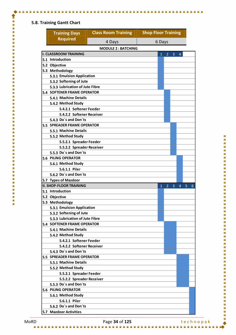
MoRD Page 34 of 125 t e c h n o p a k
5.8. Training Gantt Chart
Training Days Required
Class Room Training Shop Floor Training
4 Days 6 Days
1 2 3 4
5.1
5.2 Objective
5.3 Methodology
5.3.1
5.3.2
5.3.3
5.4
5.4.1
5.4.2
5.4.2.1 Softener Feeder
5.4.2.2 Softener Receiver
5.4.3
5.5
5.5.1
5.5.2
5.5.2.1 Spreader Feeder
5.5.2.2 Spreader Receiver
5.5.3
5.6
5.6.1
5.6.1.1 Piler
5.6.2
5.7
1 2 3 4 5 6
5.1
5.2 Objective
5.3 Methodology
5.3.1
5.3.2
5.3.3
5.4
5.4.1
5.4.2
5.4.2.1 Softener Feeder
5.4.2.2 Softener Receiver
5.4.3
5.5
5.5.1
5.5.2
5.5.2.1 Spreader Feeder
5.5.2.2 Spreader Receiver
5.5.3
5.6
5.6.1
5.6.1.1 Piler
5.6.2
5.7
PILING OPERATOR
Method Study
Do`s and Don`ts
Mazdoor Activities
Do`s and Don`ts
Emulsion Application
Softening of Jute
PILING OPERATOR
Method Study
Do`s and Don`ts
Emulsion Application
Softening of Jute
Lubrication of Jute Fibre
SOFTENER FRAME OPERATOR
Machine Details
Method Study
Method Study
SPREADER FRAME OPERATOR
II. SHOP-FLOOR TRAINING
Machine Details
Method Study
Do`s and Don`ts
Method Study
Do`s and Don`ts
Types of Mazdoor
MODULE 2 : BATCHING
I. CLASSROOM TRAINING
Introduction
Do`s and Don`ts
SPREADER FRAME OPERATOR
Machine Details
Lubrication of Jute Fibre
Introduction
SOFTENER FRAME OPERATOR
Machine Details
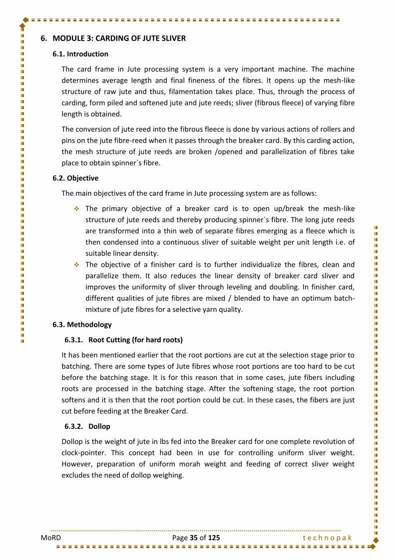
MoRD Page 35 of 125 t e c h n o p a k
6. MODULE 3: CARDING OF JUTE SLIVER
6.1. Introduction
The card frame in Jute processing system is a very important machine. The machine
determines average length and final fineness of the fibres. It opens up the mesh-like
structure of raw jute and thus, filamentation takes place. Thus, through the process of
carding, form piled and softened jute and jute reeds; sliver (fibrous fleece) of varying fibre
length is obtained.
The conversion of jute reed into the fibrous fleece is done by various actions of rollers and
pins on the jute fibre-reed when it passes through the breaker card. By this carding action,
the mesh structure of jute reeds are broken /opened and parallelization of fibres take
place to obtain spinner`s fibre.
6.2. Objective
The main objectives of the card frame in Jute processing system are as follows:
The primary objective of a breaker card is to open up/break the mesh-like
structure of jute reeds and thereby producing spinner`s fibre. The long jute reeds
are transformed into a thin web of separate fibres emerging as a fleece which is
then condensed into a continuous sliver of suitable weight per unit length i.e. of
suitable linear density.
The objective of a finisher card is to further individualize the fibres, clean and
parallelize them. It also reduces the linear density of breaker card sliver and
improves the uniformity of sliver through leveling and doubling. In finisher card,
different qualities of jute fibres are mixed / blended to have an optimum batch-
mixture of jute fibres for a selective yarn quality.
6.3. Methodology
6.3.1. Root Cutting (for hard roots)
It has been mentioned earlier that the root portions are cut at the selection stage prior to
batching. There are some types of Jute fibres whose root portions are too hard to be cut
before the batching stage. It is for this reason that in some cases, jute fibers including
roots are processed in the batching stage. After the softening stage, the root portion
softens and it is then that the root portion could be cut. In these cases, the fibers are just
cut before feeding at the Breaker Card.
6.3.2. Dollop
Dollop is the weight of jute in lbs fed into the Breaker card for one complete revolution of
clock-pointer. This concept had been in use for controlling uniform sliver weight.
However, preparation of uniform morah weight and feeding of correct sliver weight
excludes the need of dollop weighing.

MoRD Page 36 of 125 t e c h n o p a k
6.3.3. Parallelization of Jute Fibre
The process of carding involves application of draft to the fibers, thus attenuating the
fibers to an extent. The application of draft breaks the fibers further after batching stage
and improves the filamentation process. Also, the process of carding further removes any
impurities if present after the process of batching.
The Jute fibers pass through rollers with pins. As a result, combing operation takes place
and fiber parallelization takes place. This makes the jute fibers further pliable and makes
the fiber more effective to be processed in later stages.
In case of yarns, the strength highly depends on the fiber orientation. So, it can be said
that more is the degree of orientation; more would be the strength of the resultant yarn.
The process of carding thus improves the jute fiber orientation thereby, resulting in higher
strength of the resultant yarn.
6.4. Breaker Card Frame Operator
6.4.1. Machine Details
The jute reed enters into a breaker card
through its feed roller and the shell and faces
the action of high speed cylinder pins. The
mesh structure of jute reed is broken /
opened at the junction of shell-nose and
cylinder pins. The jute reed is broken into
individual filaments. The fibrous material on
the cylinder pins is leveled out by the action of
two pairs of worker-stripper rollers. The jute
fleece is finally doffed by the doffer and
emerges from the drawing roller nip and passes down through a metal conductor. Then
the fleece is condensed and passed through a slit/opening to the nip of delivery and
delivery pressing roller from where it comes out in the form of a continuous sliver. This
sliver is then wound onto a compressed roll-former placed underneath the delivery roller.
Breaker card are usually half-circular and down striking and have two pairs of worker-
stripper rollers.
The clearance/gauge between the shell and the feed roller and the feed roller and the
cylinder can be altered to give a selection of operating condition depending upon the
varieties of jute fibres to be processed.
The greater is the draft, the more will be the fibre breakage at the shell-nose. As the
quality of the yarn depends critically upon the fibre length, it is preferred to keep the draft
at an optimum level.
Fig 6.a Breaker Card Frame Machine
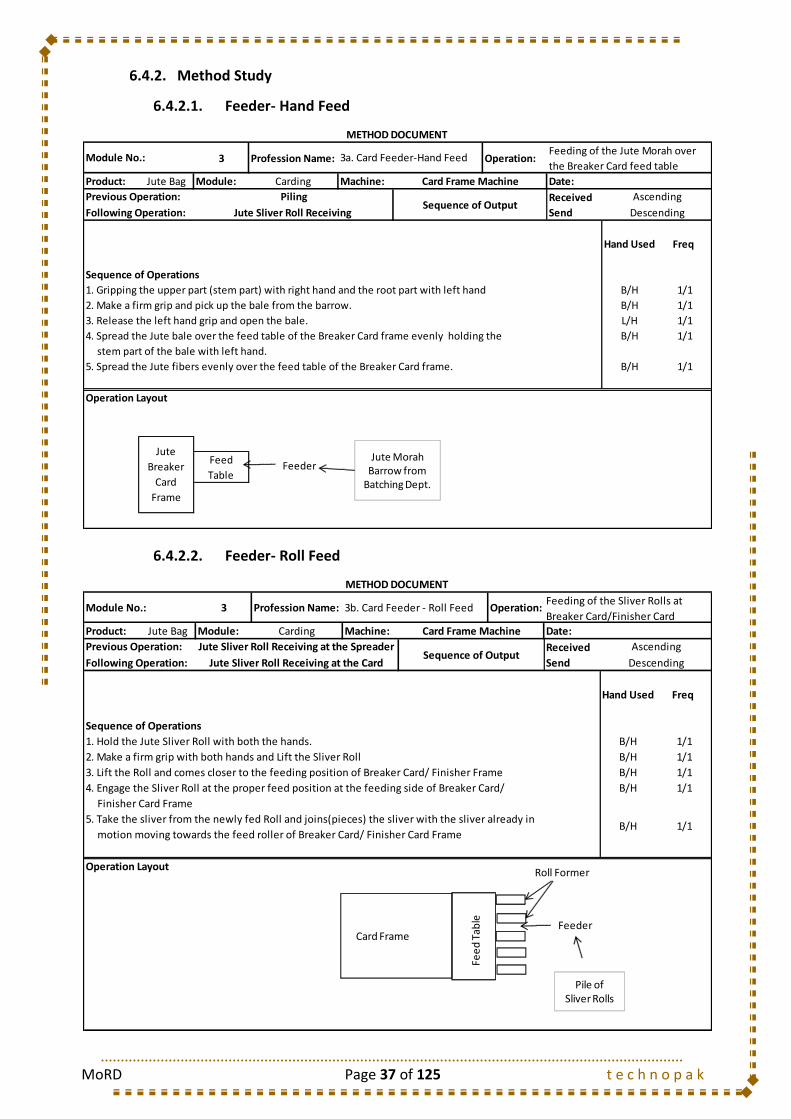
MoRD Page 37 of 125 t e c h n o p a k
6.4.2. Method Study
6.4.2.1. Feeder- Hand Feed
6.4.2.2. Feeder- Roll Feed
3 Profession Name: Operation:
Product: Jute Bag Module: Carding Machine: Date:
Received
Send
Hand Used Freq
Sequence of Operations
1. Gripping the upper part (stem part) with right hand and the root part with left hand B/H 1/1
2. Make a firm grip and pick up the bale from the barrow. B/H 1/1
3. Release the left hand grip and open the bale. L/H 1/1
4. Spread the Jute bale over the feed table of the Breaker Card frame evenly holding the B/H 1/1
stem part of the bale with left hand.
5. Spread the Jute fibers evenly over the feed table of the Breaker Card frame. B/H 1/1
Operation Layout
Jute
Breaker
Card
Frame
Feed
Table
Previous Operation: PilingSequence of Output
Ascending
Following Operation: Jute Sliver Roll Receiving Descending
METHOD DOCUMENT
Module No.: 3a. Card Feeder-Hand FeedFeeding of the Jute Morah over
the Breaker Card feed table
Card Frame Machine
FeederJute Morah
Barrow from Batching Dept.
3 Profession Name: Operation:
Product: Jute Bag Module: Carding Machine: Date:
Received
Send
Hand Used Freq
Sequence of Operations
1. Hold the Jute Sliver Roll with both the hands. B/H 1/1
2. Make a firm grip with both hands and Lift the Sliver Roll B/H 1/1
3. Lift the Roll and comes closer to the feeding position of Breaker Card/ Finisher Frame B/H 1/1
4. Engage the Sliver Roll at the proper feed position at the feeding side of Breaker Card/ B/H 1/1
Finisher Card Frame
5. Take the sliver from the newly fed Roll and joins(pieces) the sliver with the sliver already in
motion moving towards the feed roller of Breaker Card/ Finisher Card Frame
Operation Layout
Previous Operation: Jute Sliver Roll Receiving at the Spreader Sequence of Output
Ascending
Following Operation:
B/H 1/1
Jute Sliver Roll Receiving at the Card Descending
METHOD DOCUMENT
Module No.: 3b. Card Feeder - Roll FeedFeeding of the Sliver Rolls at
Breaker Card/Finisher Card
Card Frame Machine
Feeder
Pile of Sliver Rolls
Card Frame
Fee
dTa
ble
Roll Former
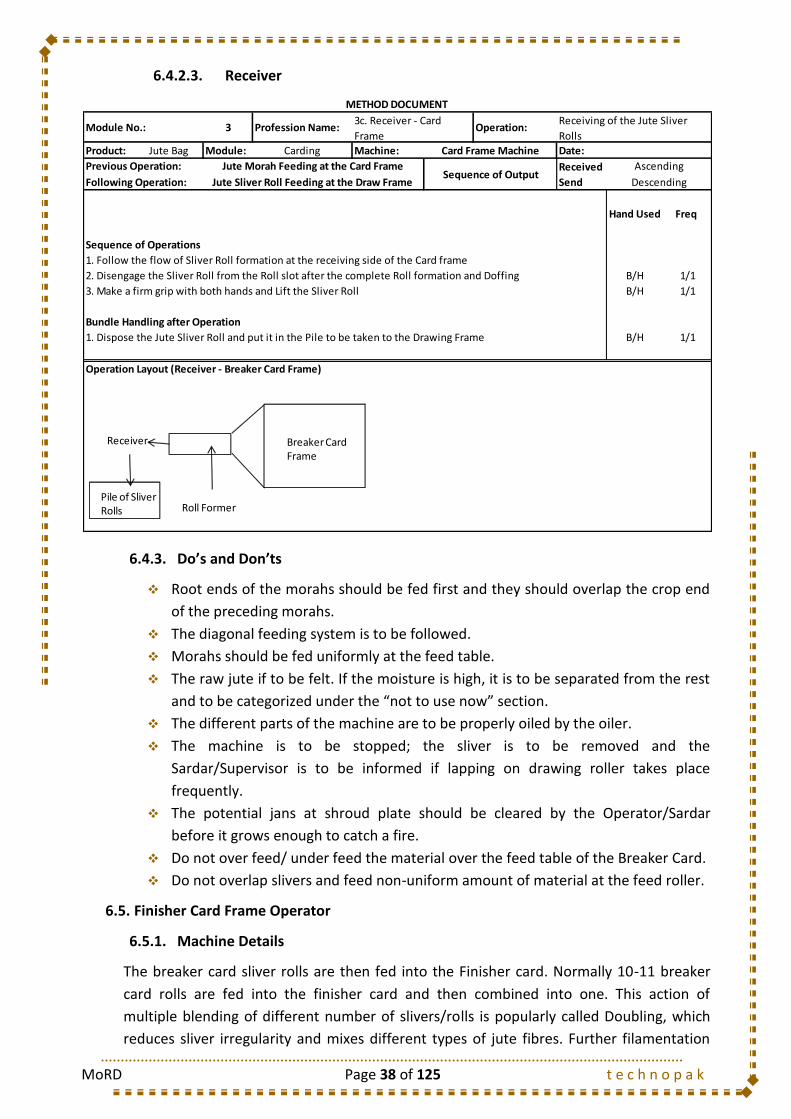
MoRD Page 38 of 125 t e c h n o p a k
6.4.2.3. Receiver
6.4.3. Do’s and Don’ts
Root ends of the morahs should be fed first and they should overlap the crop end
of the preceding morahs.
The diagonal feeding system is to be followed.
Morahs should be fed uniformly at the feed table.
The raw jute if to be felt. If the moisture is high, it is to be separated from the rest
and to be categorized under the “not to use now” section.
The different parts of the machine are to be properly oiled by the oiler.
The machine is to be stopped; the sliver is to be removed and the
Sardar/Supervisor is to be informed if lapping on drawing roller takes place
frequently.
The potential jans at shroud plate should be cleared by the Operator/Sardar
before it grows enough to catch a fire.
Do not over feed/ under feed the material over the feed table of the Breaker Card.
Do not overlap slivers and feed non-uniform amount of material at the feed roller.
6.5. Finisher Card Frame Operator
6.5.1. Machine Details
The breaker card sliver rolls are then fed into the Finisher card. Normally 10-11 breaker
card rolls are fed into the finisher card and then combined into one. This action of
multiple blending of different number of slivers/rolls is popularly called Doubling, which
reduces sliver irregularity and mixes different types of jute fibres. Further filamentation
3 Profession Name: Operation:
Product: Jute Bag Module: Carding Machine: Date:
Received
Send
Hand Used Freq
Sequence of Operations
1. Follow the flow of Sliver Roll formation at the receiving side of the Card frame
2. Disengage the Sliver Roll from the Roll slot after the complete Roll formation and Doffing B/H 1/1
3. Make a firm grip with both hands and Lift the Sliver Roll B/H 1/1
Bundle Handling after Operation
1. Dispose the Jute Sliver Roll and put it in the Pile to be taken to the Drawing Frame B/H 1/1
Operation Layout (Receiver - Breaker Card Frame)
Previous Operation: Jute Morah Feeding at the Card Frame Sequence of Output
Ascending
Following Operation: Jute Sliver Roll Feeding at the Draw Frame Descending
METHOD DOCUMENT
Module No.:3c. Receiver - Card
Frame
Receiving of the Jute Sliver
Rolls
Card Frame Machine
RRReceiver Breaker Card Frame
Roll FormerPile of Sliver Rolls
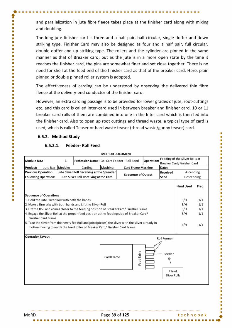
MoRD Page 39 of 125 t e c h n o p a k
and parallelization in jute fibre fleece takes place at the finisher card along with mixing
and doubling.
The long jute finisher card is three and a half pair, half circular, single doffer and down
striking type. Finisher Card may also be designed as four and a half pair, full circular,
double doffer and up striking type. The rollers and the cylinder are pinned in the same
manner as that of Breaker card; but as the jute is in a more open state by the time it
reaches the finisher card, the pins are somewhat finer and set close together. There is no
need for shell at the feed end of the finisher card as that of the breaker card. Here, plain
pinned or double pinned roller system is adopted.
The effectiveness of carding can be understood by observing the delivered thin fibre
fleece at the delivery-end conductor of the finisher card.
However, an extra carding passage is to be provided for lower grades of jute, root-cuttings
etc. and this card is called inter-card used in between breaker and finisher card. 10 or 11
breaker card rolls of them are combined into one in the Inter card which is then fed into
the finisher card. Also to open up root cuttings and thread waste, a typical type of card is
used, which is called Teaser or hard waste teaser (thread waste/gunny teaser) card.
6.5.2. Method Study
6.5.2.1. Feeder- Roll Feed
3 Profession Name: Operation:
Product: Jute Bag Module: Carding Machine: Date:
Received
Send
Hand Used Freq
Sequence of Operations
1. Hold the Jute Sliver Roll with both the hands. B/H 1/1
2. Make a firm grip with both hands and Lift the Sliver Roll B/H 1/1
3. Lift the Roll and comes closer to the feeding position of Breaker Card/ Finisher Frame B/H 1/1
4. Engage the Sliver Roll at the proper feed position at the feeding side of Breaker Card/ B/H 1/1
Finisher Card Frame
5. Take the sliver from the newly fed Roll and joins(pieces) the sliver with the sliver already in
motion moving towards the feed roller of Breaker Card/ Finisher Card Frame
Operation Layout
Previous Operation: Jute Sliver Roll Receiving at the Spreader Sequence of Output
Ascending
Following Operation:
B/H 1/1
Jute Sliver Roll Receiving at the Card Descending
METHOD DOCUMENT
Module No.: 3b. Card Feeder - Roll FeedFeeding of the Sliver Rolls at
Breaker Card/Finisher Card
Card Frame Machine
Feeder
Pile of Sliver Rolls
Card Frame
Fee
dTa
ble
Roll Former
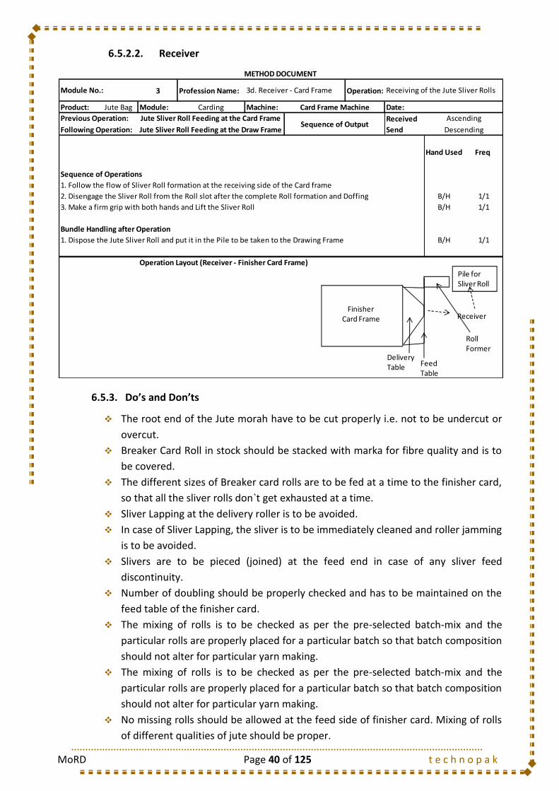
MoRD Page 40 of 125 t e c h n o p a k
6.5.2.2. Receiver
6.5.3. Do’s and Don’ts
The root end of the Jute morah have to be cut properly i.e. not to be undercut or
overcut.
Breaker Card Roll in stock should be stacked with marka for fibre quality and is to
be covered.
The different sizes of Breaker card rolls are to be fed at a time to the finisher card,
so that all the sliver rolls don`t get exhausted at a time.
Sliver Lapping at the delivery roller is to be avoided.
In case of Sliver Lapping, the sliver is to be immediately cleaned and roller jamming
is to be avoided.
Slivers are to be pieced (joined) at the feed end in case of any sliver feed
discontinuity.
Number of doubling should be properly checked and has to be maintained on the
feed table of the finisher card.
The mixing of rolls is to be checked as per the pre-selected batch-mix and the
particular rolls are properly placed for a particular batch so that batch composition
should not alter for particular yarn making.
The mixing of rolls is to be checked as per the pre-selected batch-mix and the
particular rolls are properly placed for a particular batch so that batch composition
should not alter for particular yarn making.
No missing rolls should be allowed at the feed side of finisher card. Mixing of rolls
of different qualities of jute should be proper.
3 Profession Name: Operation:
Product: Jute Bag Module: Carding Machine: Date:
Received
Send
Hand Used Freq
Sequence of Operations
1. Follow the flow of Sliver Roll formation at the receiving side of the Card frame
2. Disengage the Sliver Roll from the Roll slot after the complete Roll formation and Doffing B/H 1/1
3. Make a firm grip with both hands and Lift the Sliver Roll B/H 1/1
Bundle Handling after Operation
1. Dispose the Jute Sliver Roll and put it in the Pile to be taken to the Drawing Frame B/H 1/1
Operation Layout (Receiver - Finisher Card Frame)
Previous Operation: Jute Sliver Roll Feeding at the Card Frame Sequence of Output
Ascending
Following Operation: Jute Sliver Roll Feeding at the Draw Frame Descending
METHOD DOCUMENT
Module No.: 3d. Receiver - Card Frame Receiving of the Jute Sliver Rolls
Card Frame Machine
Pile for Sliver Roll
FinisherCard Frame
DeliveryTable Feed
Table
RollFormer
Receiver

MoRD Page 41 of 125 t e c h n o p a k
6.6. Types of Mazdoor
S. No. Mazdoor Type Job Description
1 Carrier Carries the Jute Morahs after Piling to the Carding Department
6.7. Training Gantt Chart
Training Days Required
Class Room Training Shop Floor Training
5 Days 10 Days
1 2 3 4 5
6.1
6.2
6.3
6.3.1
6.3.2
6.3.3
6.4
6.4.1
6.4.2
6.4.2.1 Feeder- Hand Feed
6.4.2.2 Feeder- Roll Feed
6.4.2.3 Receiver
6.4.3
6.5
6.5.1
6.5.2
6.5.2.1 Feeder- Hand Feed
6.5.2.2 Feeder- Roll Feed
6.5.2.3 Receiver
6.5.3
6.6
1 2 3 4 5 6 7 8 9 10
6.1
6.2
6.3
6.3.1
6.3.2
6.3.3
6.4
6.4.1
6.4.2
6.4.2.1 Feeder- Hand Feed
6.4.2.2 Feeder- Roll Feed
6.4.2.3 Receiver
6.4.3
6.5
6.5.1
6.5.2
6.5.2.1 Feeder- Hand Feed
6.5.2.2 Feeder- Roll Feed
6.5.2.3 Receiver
6.5.3
6.6
Do`s and Don`ts
Machine Details
Method Study
Machine Details
Do`s and Don`ts
Method Study
Types of Mazdoor
MODULE 3 : CARDING
II. SHOP-FLOOR TRAINING
Introduction
Root Cutting (for hard roots)
Dollop
Parallelization of Jute Fibres
Objective
Methodology
Objective
Methodology
Method Study
Mazdoor Activities
BREAKER CARD FRAME OPERATOR
Machine Details
Method Study
FINISHER CARD FRAME OPERATOR
BREAKER CARD FRAME OPERATOR
Do`s and Don`ts
FINISHER CARD FRAME OPERATOR
Machine Details
I. CLASSROOM TRAINING
Introduction
Root Cutting (for hard roots)
Dollop
Parallelization of Jute Fibres
Do`s and Don`ts
MoRD Page 42 of 125 t e c h n o p a k
7. MODULE 4: DRAWING OF JUTE SLIVER
7.1. Introduction
Summarizing so far, the process of jute processing involved the breaking of Jute fibers,
attenuation of the fibers by application of draft, opening and individualization of Jute
fibers. Attenuation of the slivers i.e. drafting of the slivers increases the sliver irregularity.
Thus, drafting and doubling (mixing) of slivers is done simultaneously in this process.
Generally, three drawing operation stages are involved for processing of finer yarns for
Hessian quality and two drawing operation stages are involved for processing of coarser
yarns for Sacking weft quality.
In each of the three drawing passages, the jute slivers are drafted and then doubled. As a
result of this, the two main operations take place:
Further Opening and individualization of jute fibre, and
Reduction of Jute sliver irregularity by doubling of jute fibers.
7.2. Objective
Parallelization / Straightening of fibers along the length of the sliver.
Reduction of sliver weight irregularity by doubling.
Attenuation or reduction of sliver weight by drafting.
Mixing of different types of fibers, if required.
7.3. Methodology
7.3.1. Attenuation of Jute Sliver
There are mainly two types of drawing frames available for drawing operation of jute
sliver. These are, namely, push bar and screw gill drawing frames. The sliver enters the
drawing machine between the retaining rollers & a self weighted jockey-rollers and then
meet the gill pins. The gill pins are carried on a series of faller bars. As the sliver leaves the
nip of the back roller, a faller bar with its sharp pins strike upwards into the slivers and
fibres are impaled on the gill pins. The faller bars move towards as a sheet and carry the
sliver to the front of the machine. When the faller-bars are close to the drawing rollers,
they drop out of the sliver and travel back under the sliver in preparation for another
stroke upwards. The relative surface speed of the drawing and retaining rollers normally
defines the draft of the frame. If the lead between the faller and the retaining roller is low,
the sliver will ride on the top of the pins and as a result of drafting, the fibres will suddenly
be accumulated at the nip of the drawing roller and emerged from the machine resulting
in the formation of thick and thin places in the sliver. So, the pin in the faller bar should
not be blunt, bent, broken or missing.
7.3.2. Doubling of the Slivers
After passing the Drafting the slivers undergo a doubling operation where the two or
more sliver flows are combined into one thus resulting in the delivery of a single sliver. As
a result of this, the sliver irregularity gets minimized. Also, the count CV% of the resultant
yarn gets reduced due to the doubling. Drawing of the jute fibres is a very important

MoRD Page 43 of 125 t e c h n o p a k
process where the sliver irregularity and also the resultant yarn irregularity can be
controlled to a much larger extent.
7.4. Drawing Frame Operator
7.4.1. Machine Details
7.4.1.1. Mackhigh Push Bar Drawing machine
This machine has single crank bar and only one track for controlling the bars but keeping
the faller speed as high as ordinary push bar drawing frame. The crank is bent at 450 and
end of the crank gets in the pin control track. The outer track is formed by five small
pieces which are fixed to the side gable and the inner one is placed inside the five pieces
and also fixed on the side gable. Out of above five pieces, two top ones acts as bridge
pieces. The narrow bead having fallers are placed by the side of the inner side so that they
are not getting any end long motion or side way motion. The tilting of the bars are
prevented by the top pieces of the outer track. The pitch of the carrier wheel is double the
pitch of the bar and thereby two pieces drops for each revolution of the wheel. Thus, the
faller drops are very high.
7.4.1.2. Screw Gill / Spiral Drawing machine
This machine has one pair of screw in both side of the faller bar which are directly fitted
with one another. Faller bars are driven by these screws. Two sides of each faller bar has a
cutting in such a way that sides are fitted with a gap of screws and faller bars move
forward by rotation of screws. When each faller bar comes at the end of top screw, it falls
on the adjacent bottom screw by means of a cam. When the faller bars fall one by one
from the gap of top screw to bottom screw, those bars are tightly held by means of spring.
The gap between the bottom screws is comparatively wider than that of top screw, so
that faller bars can reach the back side very quickly. The gap between bottom screws is
wider, so that less number of faller bars is required to complete the cycle. Thus the
bottom screws are coarser in pitch than the top screws. Also the cams are fitted at the
end of the screws to the ascent of bars. There are check-levers fitted in front and back on
brackets along with the springs. The back check levers are hooked at the top to prevent
throwing of the bars.
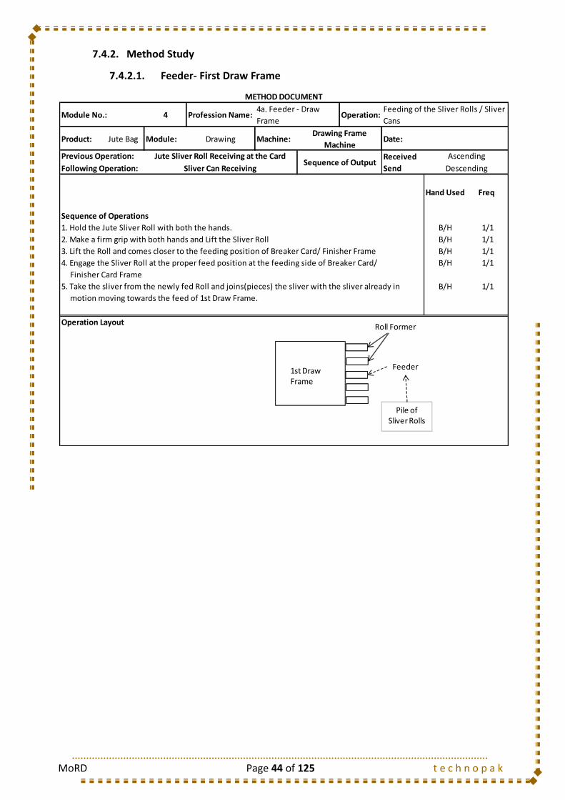
MoRD Page 44 of 125 t e c h n o p a k
7.4.2. Method Study
7.4.2.1. Feeder- First Draw Frame
4 Profession Name: Operation:
Product: Jute Bag Module: Drawing Machine: Date:
Received
Send
Hand Used Freq
Sequence of Operations
1. Hold the Jute Sliver Roll with both the hands. B/H 1/1
2. Make a firm grip with both hands and Lift the Sliver Roll B/H 1/1
3. Lift the Roll and comes closer to the feeding position of Breaker Card/ Finisher Frame B/H 1/1
4. Engage the Sliver Roll at the proper feed position at the feeding side of Breaker Card/ B/H 1/1
Finisher Card Frame
5. Take the sliver from the newly fed Roll and joins(pieces) the sliver with the sliver already in B/H 1/1
motion moving towards the feed of 1st Draw Frame.
Operation Layout
Descending
METHOD DOCUMENT
Module No.:4a. Feeder - Draw
Frame
Feeding of the Sliver Rolls / Sliver
Cans
Drawing Frame
Machine
Previous Operation: Jute Sliver Roll Receiving at the Card Sequence of Output
Ascending
Following Operation: Sliver Can Receiving
Feeder
Pile of Sliver Rolls
1st DrawFrame
Roll Former
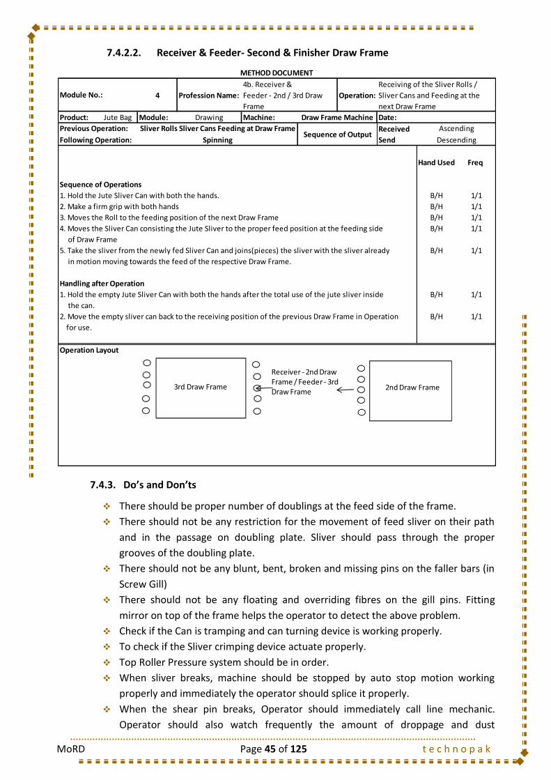
MoRD Page 45 of 125 t e c h n o p a k
7.4.2.2. Receiver & Feeder- Second & Finisher Draw Frame
7.4.3. Do’s and Don’ts
There should be proper number of doublings at the feed side of the frame.
There should not be any restriction for the movement of feed sliver on their path
and in the passage on doubling plate. Sliver should pass through the proper
grooves of the doubling plate.
There should not be any blunt, bent, broken and missing pins on the faller bars (in
Screw Gill)
There should not be any floating and overriding fibres on the gill pins. Fitting
mirror on top of the frame helps the operator to detect the above problem.
Check if the Can is tramping and can turning device is working properly.
To check if the Sliver crimping device actuate properly.
Top Roller Pressure system should be in order.
When sliver breaks, machine should be stopped by auto stop motion working
properly and immediately the operator should splice it properly.
When the shear pin breaks, Operator should immediately call line mechanic.
Operator should also watch frequently the amount of droppage and dust
4 Profession Name: Operation:
Product: Jute Bag Module: Drawing Machine: Date:
Received
Send
Hand Used Freq
Sequence of Operations
1. Hold the Jute Sliver Can with both the hands. B/H 1/1
2. Make a firm grip with both hands B/H 1/1
3. Moves the Roll to the feeding position of the next Draw Frame B/H 1/1
4. Moves the Sliver Can consisting the Jute Sliver to the proper feed position at the feeding side B/H 1/1
of Draw Frame
5. Take the sliver from the newly fed Sliver Can and joins(pieces) the sliver with the sliver already B/H 1/1
in motion moving towards the feed of the respective Draw Frame.
Handling after Operation
1. Hold the empty Jute Sliver Can with both the hands after the total use of the jute sliver inside B/H 1/1
the can.
2. Move the empty sliver can back to the receiving position of the previous Draw Frame in Operation B/H 1/1
for use.
Operation Layout
Previous Operation: Sliver Rolls Sliver Cans Feeding at Draw FrameSequence of Output
Ascending
Following Operation: Spinning Descending
METHOD DOCUMENT
Module No.:
4b. Receiver &
Feeder - 2nd / 3rd Draw
Frame
Receiving of the Sliver Rolls /
Sliver Cans and Feeding at the
next Draw Frame
Draw Frame Machine
2nd Draw Frame3rd Draw Frame
Receiver - 2nd Draw Frame / Feeder - 3rd Draw Frame

MoRD Page 46 of 125 t e c h n o p a k
deposited underneath the drawing machine and if droppage collection is too
much, the dust mazdoor should be called to remove it. In case of higher
droppages, the supervisor should be informed.
There should be no objectionable/unusual sound in the machine. Hence, operator
occasionally should hear the machine sound attentively.
Operator should understand about the quality of sliver particularly about the thick-
thin places and accordingly operator should watch quality of produces sliver
carefully.
After doffing the sliver can in running condition, the operator should clean the
machine and surrounding area. Can-marka or colour of can as an indication mark
of sliver quality should be properly maintained.
Crimp box weight should be at proper place in finisher drawing machine.
Occasionally, the drawing roller surface is to be checked and the sardar should be
informed on the occurrence of such scratch mark.
Operator should attentively check the condition the condition of pins on the faller
bar. The sardar/supervisor or the line mechanic should be informed if any of the
pins are blunt/broken/missing and to be rectified.
Operator should keep the feed materials and delivered materials with proper
coverings, so that, there is no undue loss of moisture from the slivers.
Operator should clean machine and lubricate the machine after each shift.
Doffing of sliver can after stopping the machine should be avoided. All the sliver
cans should not be exhausted at a time.
Can identification mark as per quality should be properly maintained.
If there is lapping or jam on any drawing machine, operator should immediately
attend it to remove the lapping/jam, without use of knife. Knife can cause scratch
mark on the rollers, which is undesirable.
Before placing empty sliver can, operator should check that there should be no
remnant of old sliver at the inside bottom of the can. Only empty can should be
placed.
Operator should be watchful about the routine cleaning, lubrication and picking
job at each shift.
7.5. Types of Mazdoor
S. No. Mazdoor Type Job Description
1 Can Mazdoor Shifts the Jute Sliver Cans to different zone as per requirement

MoRD Page 47 of 125 t e c h n o p a k
7.6. Training Gantt Chart
Training Days Required
Class Room Training Shop Floor Training
4 Days 5 Days
1 2 3 4
7.1
7.2
7.3
7.3.1
7.3.2
7.3.3
7.4
7.4.1
7.4.2
7.4.2.1 Feeder- First Draw Frame
7.4.2.2 Receiver & Feeder- Second & Finisher Draw
Frame
7.4.3
7.5
1 2 3 4 5
7.1
7.2
7.3
7.3.1
7.3.2
7.3.3
7.4
7.4.1
7.4.2
7.4.2.1 Feeder- First Draw Frame
7.4.2.2 Receiver & Feeder- Second & Finisher Draw
Frame
7.4.3
7.5
Attenuation of Jute Sliver
Methodology
Do`s and Don`ts
Mazdoor Activities
DRAWING FRAME OPERATOR
Machine Details
Method Study
Doubling of the Slivers
Fibre Orientation and Parallelization
Fibre Orientation and Parallelization
DRAWING FRAME OPERATOR
Machine Details
Method Study
Types of Mazdoor
Objective
Introduction
MODULE 4 : DRAWING
I. CLASSROOM TRAINING
Introduction
Objective
Methodology
Attenuation of Jute Sliver
Do`s and Don`ts
II. SHOP-FLOOR TRAINING
Doubling of the Slivers

MoRD Page 48 of 125 t e c h n o p a k
8. MODULE 5: SPINNING OF JUTE SLIVER
8.1. Introduction
Normally a finisher drawing sliver (third passage in case of fine yarns and second passage
in case of coarse yarns) is used as a feed material of spinning frame.
The majority of jute yarns are spun from finisher drawing crimped sliver, which is
contained in can for 25-30 hours capacity individually. The essential features of the
spinning frame are drafting, twisting and winding. The mechanism of twisting and winding
functions is common and integral, although there is some difference adopted in
controlling fiber motion during drafting in drafting zone of different types of jute spinning
machines.
All types of Jute Spinning frame have three common zones – Creel Zone, Drafting Zone
and Twisting Zone & Winding Zone.
Creel Zone, where finisher drawing cans (sliver of 25 to 30 hours feeding capacity)
are placed in a manner to feed individual spindle of the spinning frames.
Drafting Zone, where jute fibers are subjected to drafting thereby reducing the
number of fibers in the cross-section as well as straightening and parallelization of
the fibers.
Twisting & Winding Zone, where drafted fiber strand is twisted and then wound
on a bobbin with the help of flyer and bobbin.
8.2. Objective
To reduce the number if fibres in the cross-section according to the count of the
yarn.
To impart twist to form the final yarn structure.
To wind the yarn on a bobbin maintaining proper yarn tension.
8.3. Methodology
8.3.1. Attenuation of Jute Sliver
Jute Slivers are further drafted in the process of spinning before being spun into a yarn. As
already discussed, the orientation and parallelization of the fibers has a great influence
over the strength and quality of the resultant yarn.
In this process, the jute fiber individualization takes place further and makes the jute sliver
ready to be spun. In case the fibers does not get oriented in the jute sliver, after spinning,
only one component of the fiber strength will be contributed to the yarn strength. The
straighter the fiber is, the larger the strength component would be and greater would be
the strength of the yarn.
8.3.2. Twisting of the Sliver
Twisting is the process of conversion of Jute sliver into the yarn. Jute Spinning Frame
inserts twist by means of overhung flyers suspended above the bobbins which are rotated
by the yarn pulling them round.

MoRD Page 49 of 125 t e c h n o p a k
A sliver is twisted to increase the coherence between the fibers.
The more would be the fiber-to-fiber coherence in the fibers,
the more would be its contribution to yarn strength. The
majority of End Breakages in the Jute Processing takes place due
to the slippage of fibers. On application of tension, the fibers
tend to slip and eventually yarn breakage takes place. This
happens due to less fiber-to-fiber coherence. Thus the process
of twisting greatly influences fiber cohesion in the sliver which
again influences the End Breakage Rate during the Jute
processing in later stages.
8.3.3. Winding of the Yarn
The spinning bobbin is mounted in between the two flyer legs. The yarn actually passes
through the flyer eye to the bobbin. Every rotation of the flyer imparts twist to the
resultant yarn. The rotation of the flyer also winds yarn on the spinning bobbin. Both the
spinning bobbin and the flyer rotate, there being a speed differential system between
flyer and bobbin.
The Flyer gets its motion from the motor via pulleys and having constant speed through
full doff. The rotational movement of bobbins depends on yarn tension, which on the
other hand depends on flyer rotation.
8.3.4. Doffing of the Yarn Bobbins
Semi-Automatic Doffing System is present in all spinning frames. When the Bobbins are
full, the frame is stopped with the Builder-Rail as near the bottom of the traverse as
possible. By pushing in a clutch lever, the builder is brought into gear with the Auto
Doffing Arrangement, which is operated by a hand wheel and a traverse gear, then is
disconnected by pulling out the spring-loaded clutch-pin. The hand wheel is then released
and the Builder-Rail lowered out of traverse on to the Bracket where it presses down the
counter balance weight of the catch. The Rail is then slid forward by operating a foot-
wheel, thus bringing the Builder-Rail with the empty bobbins into position. When the
Builder-Rail with the empty bobbins is lifted by operating the hand wheel, the clutch-pin
snaps home as soon as the builder reaches the position from which it was disconnected,
thus brings the traverse gearing into operation. The clutch-lever is then pulled out thereby
disconnecting the auto-doffing arrangement (otherwise the machine would not start). A
few turns of yarn are wound on the bobbins and the ends cut; thereafter, the frame is
started up to speed and is individual automatic stop motion is brought into operation by
depressing another lever situated just above the starting lever. The full bobbins are
replaced by empty bobbins is then slid to the backward position by operating the foot-
wheel. When the rail reaches this position, the bracket is slid forward again by operating
the foot wheel in the reverse direction. As soon as the bracket reaches the proper
position, the counter –balance weight is released from under the rail and the catch snaps
up and holds the rail in position, and the mechanism is ready for the next doffing.
Fig 8.a Twisting of the Sliver
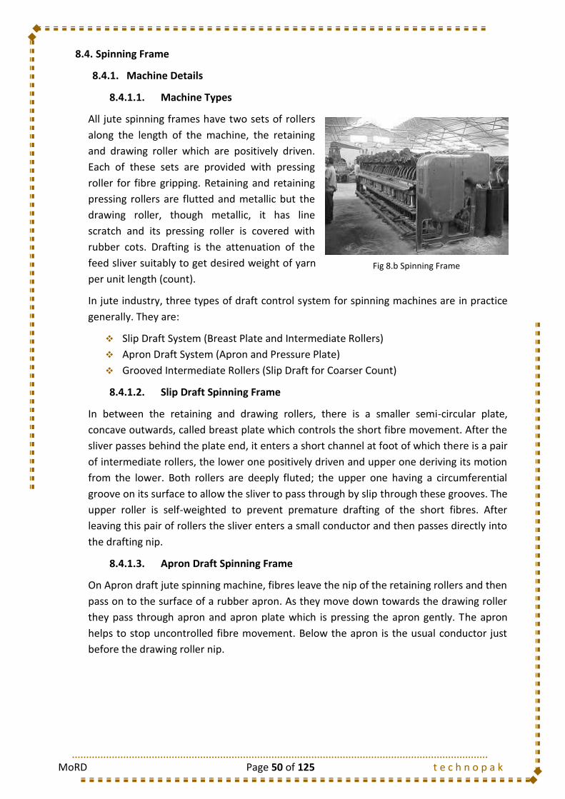
MoRD Page 50 of 125 t e c h n o p a k
8.4. Spinning Frame
8.4.1. Machine Details
8.4.1.1. Machine Types
All jute spinning frames have two sets of rollers
along the length of the machine, the retaining
and drawing roller which are positively driven.
Each of these sets are provided with pressing
roller for fibre gripping. Retaining and retaining
pressing rollers are flutted and metallic but the
drawing roller, though metallic, it has line
scratch and its pressing roller is covered with
rubber cots. Drafting is the attenuation of the
feed sliver suitably to get desired weight of yarn
per unit length (count).
In jute industry, three types of draft control system for spinning machines are in practice
generally. They are:
Slip Draft System (Breast Plate and Intermediate Rollers)
Apron Draft System (Apron and Pressure Plate)
Grooved Intermediate Rollers (Slip Draft for Coarser Count)
8.4.1.2. Slip Draft Spinning Frame
In between the retaining and drawing rollers, there is a smaller semi-circular plate,
concave outwards, called breast plate which controls the short fibre movement. After the
sliver passes behind the plate end, it enters a short channel at foot of which there is a pair
of intermediate rollers, the lower one positively driven and upper one deriving its motion
from the lower. Both rollers are deeply fluted; the upper one having a circumferential
groove on its surface to allow the sliver to pass through by slip through these grooves. The
upper roller is self-weighted to prevent premature drafting of the short fibres. After
leaving this pair of rollers the sliver enters a small conductor and then passes directly into
the drafting nip.
8.4.1.3. Apron Draft Spinning Frame
On Apron draft jute spinning machine, fibres leave the nip of the retaining rollers and then
pass on to the surface of a rubber apron. As they move down towards the drawing roller
they pass through apron and apron plate which is pressing the apron gently. The apron
helps to stop uncontrolled fibre movement. Below the apron is the usual conductor just
before the drawing roller nip.
Fig 8.b Spinning Frame

MoRD Page 51 of 125 t e c h n o p a k
8.4.1.4. Machine Specifications
No. of Spindle Generally 100 spindles for
inches and
inches pitch machine and 80
spindles for
inches and 6 inches pitch machine. Some of the mills have
110 spindles
inches pitch apron draft machine.
Pitch of the Spindle
:
,
,
, 6 inches
Lift : 6, 7.50, 4.5 inches etc.
Bobbin Size 1.6 in.× 7.5 in., 6.5 in. × 3 in., 5.75 in. × 2.625 in. etc.
Count Range 4-16 lbs/spindle in
and
inches pitch machine.
20-35 lbs./spindle in 5.5 and 6 inches pitch machine
Drive Left or Right hand lenix drive machine is available
Silver Stop Motion
Mechanical sliver stop motion is available (optionally Pneumafil sliver suction device in lieu of stop motion particularly in apron draft spinning machine)
Flyer Speed 3200 to 4200 rpm for finer count and 1800 to 2700 rpm for coarser count of yarns
8.4.1.5. Pitch
This is commonly known as spindle pitch of spinning machine. It is the distance between
the two consecutive spindle centres. For coarser side the pitch should be higher, usually
inch and for finer side the pitch is lower, usually
inch.
8.4.1.6. Lift
It is the amount of total upward and downward linear movement of the carriage of
spinning bobbins for perfect winding of the yarn and building of the bobbins.
8.4.1.7. Spindle R.P.M.
It is the number of circular rotation of spinning spindle per minute, indicating the speed of
twisting and winding of the yarn.
8.4.1.8. Twist Constant
Twist is the turns about their axes of fibres in yarns. It is obtained by the revolution of the
spinning flyer relative to the delivery roller speed.
8.4.1.9. Draft Constant
Draft is the amount of attenuation given as expressed by the ratio of the surface speed of
the Fast moving rollers to that of the slow moving rollers, to obtain proportionate
reduction of the number/weight of fibres per unit length than that of initial fibre
aggregate/sliver. Thus, it is the method of reducing the size of a fibre aggregate by
advancing it through pairs of rollers moving with progressively higher surface speed. Draft
constant is a machine constant obtained by the surface speed ratio of drawing roller to
retaining roller considering the change pinion as unity.

MoRD Page 52 of 125 t e c h n o p a k
8.4.2. Method Study
8.4.2.1. Spinner
8.4.3. Do’s and Don’ts
Follow the proper identification marks/colour of sliver cans for different qualities
of yarn making. Use finisher drawing can with same identification mark.
Follow the identification marks/colour of yarns, frame number, Draft change
pinion (DCP) and Twist Change Pinion (TCP) on spinning machines.
Mark the bobbins for different quality of yarns.
Maintain uniform bobbin weight.
Use felt bobs with same life span.
5 Profession Name: Operation:
Product: Jute Bag Module: Spinning Machine: Date:
Received
Send
Handling before Operation Hand Used Freq
1. Hold the Jute Sliver Can with both the hands. B/H 1/1
2. Moves the Roll to the feeding position of the Spinning Frame B/H 1/1
Sequence of Operations
1. Take out the Jute Sliver from the Jute Sliver Can with right hand. R/H 1/1
2. Pass the sliver through the machine parts and join the newly fed sliver with the sliver already B/H 1/1
running in the machine.
3. Mount the empty spinning bobbins for winding by engaging them at the respective slots
4. Follow the winding of yarn on the spinning bobbin. B/H 1/1
5. Piece the yarn (in case of End Breakage) B/H 1/1
L/H 1/1
B/H 1/1
B/H 1/1
B/H 1/1
B/H 1/1
B/H 1/1
R/H 1/1
B/H 1/1
R/H 1/1
B/H 1/1
R/H 1/1
Handling after Operation
1. Despatch the full spinning packages to the barrow to be taken to winding and replace them B/H 1/1
with empty ones.
Operation Layout
Ascending
Following Operation: Winding Descending
METHOD DOCUMENT
Module No.: 5.a Spinner Attending Spinning machine
Spinning Machine
(g) Pull the grooved wire and take it out of the wharve along with the wire.
(h) Release the left hand grip on the wharve cap and let it rotate again.
(i) Take the yarn out of the wire groove with right hand holding the wire with left hand.
Previous Operation: Sliver Can Receiving at the Draw FrameSequence of Output
(a) Make a firm grip at the rotating wharve cap (stopping it) with the left hand
(b) Pass a thin grooved wire through the small hole on the wharve cap with right hand.
(c) Find the yarn end on the wound spinning bobbin.
(d) Unwind the spinning bobbin slightly to take out the yarn.
(e) Engage the yarn at the respective flyer-eye with right hand
(f) Engage the yarn at the groove of the wire passid inside through the wharve cap hole.
(j) Put the wire in the shirt pocket.
(k) Take the yarn with the right hand, and guide it to the retaining roller nip simultaneously
Spinning Frame
Spinner
Spinning Bobbin Barrow
MoRD Page 53 of 125 t e c h n o p a k
Follow all the instructions of supervisor in case of quality change and use proper
identification marks, as instructed.
Use coloured yarn for making in lieu of hooks when necessary for export yarn.
Tie waste bag at proper place at the start of the shift as instructed.
Clean the machine parts and surroundings properly at the start of the shift.
Set bobbin on carrier wheels properly.
Take immediate remedial measures to run the idle spindle.
At the start, understand previous shift`s working from earlier shift`s operator.
Follow the scheduled duties and responsibilities of a spinning operator. However,
in case of sliver shortage or excessive end breakages, take measure as per
instruction of line sardar/supervisor.
Work in a safe and attentive way to avoid accidents.
Check and arrange to replace worn-out pressing roller, broken yarn detector,
broken porcelain flyer-eye, worn-out leather wiper, defective bobbin carrier,
broken or defective bobbin heads, damaged felt bobs etc. if found.
Before sending back the empty sliver cans to drawing department, make it sure
that the can is thoroughly empty.
Occasionally clean the spinning machine by air blow, but in idle condition only.
Use graphite powder lubricant (no grease or oil) in builder rail for correct bobbin
building.
Check the position of the felt bob and report the concerned supervisor for
replacement, if necessary.
Remove badly fit and damaged bobbin.
Avoid rough handling of the bobbins.
Keep each type of sliver/thread thread waste in the waste bag separately.
Occasionally check the condition of apron or depth or the groove in grooved idler
roller and report the concerned supervisors if necessary.
Avoid “Morah Mara” system during doffing time. This is a bad practice and to be
avoided.
Attend end breakages systematically by proper piecing taking optimum time.
Ensure sliver feeding from can, avoid rubbing of slivers against riveted can wall.
Keep watch on the stock of full sliver can and dispose of empty can at the back of
the spinning frame.
Feed sliver from can without wasting good sliver.
Piece-up the yarn with minimum length without causing generation of thick place.
Clean the idler roller, pneumatic pipes etc. when necessary.
Keep the reserve bobbins and created bobbins free from fluff, dust and yarn
accumulation.
Don`t use any knife during bobbin cleaning.
Inform the concerned Supervisor/Sardar if any spindle is observed with less
lubricated of running without lube oil.
Inform your supervisors, if ball-container and spring is not available.
Inform the superior immediately regarding damaging and repairing of cotton tape.

MoRD Page 54 of 125 t e c h n o p a k
Leave the work spot only after giving the charge to reliever for going out from
work place for personal needs and for nature`s call.
8.4.4. Do’s and Don’ts
There are various reasons for end breaks in jute sliver spinning machine. In general, it can
be explained that whenever the yarn is not able to withstand the spinning tension, there
will be end breaks causing loss in efficiency thereby lowering production.
Causes of End Breakages / Yarn Breaks in Spinning:
Due to feed material
Irregular Sliver
High variation in sliver weight
Improper moisture
Presence of roots and specs in sliver
Due to Spinning Frame
Wrong selection of machine parameters like spindle speed, twist and their high
variations, high draft etc.
Improper setting of machine components like breast plate, front conductor etc.
Improper position of the felt bobs under the bobbin carriers.
Improper wrapping of yarn on the flyer.
Broken machine components specially gears.
Improper movement of rollers.
Poor maintenance of the machine.
8.5. Types of Mazdoor
S. No. Mazdoor Type Job Description
1 Spinning Bobbin Carrying Mazdoor (Bobbin Carrier)
Carries the Spinning bobbin from Spinning Department to Winding Department and Bring back the empty bobbins from Winding Department to Spinning Department
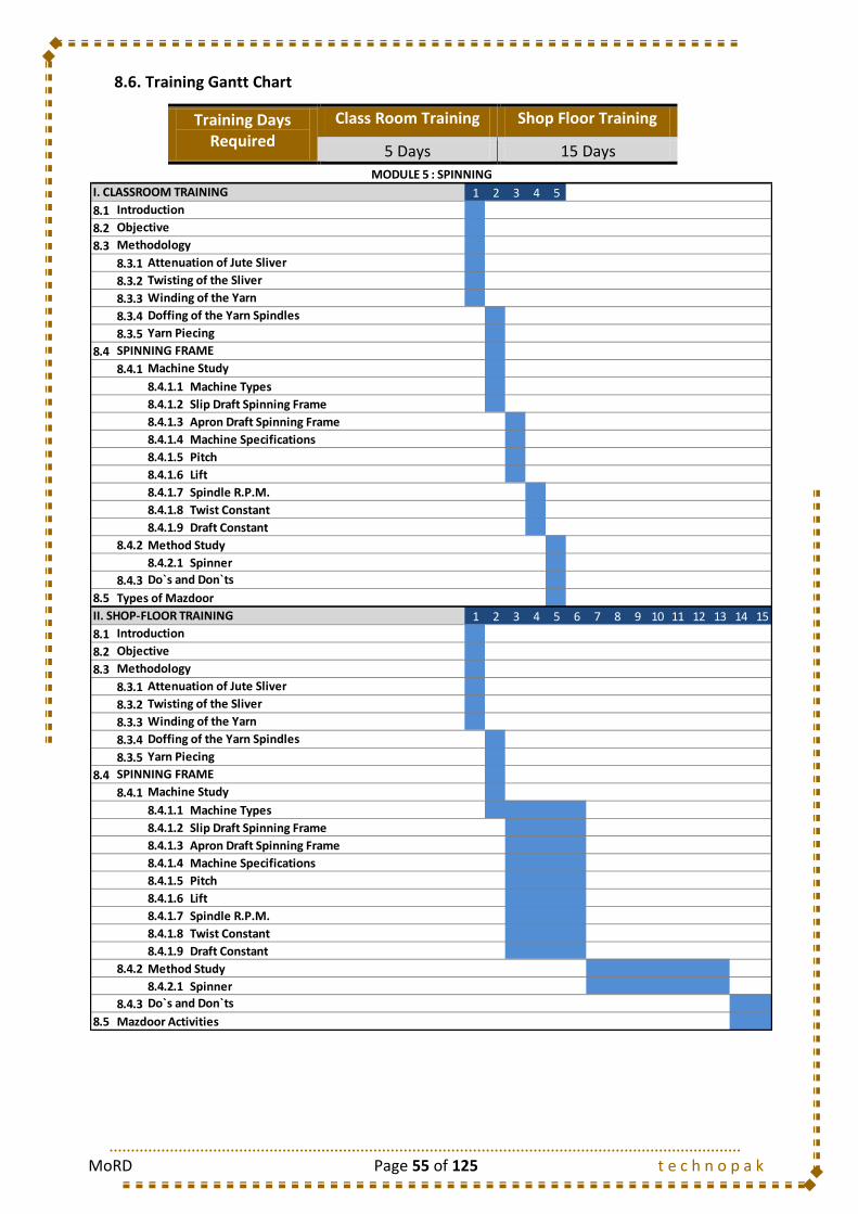
MoRD Page 55 of 125 t e c h n o p a k
8.6. Training Gantt Chart
Training Days Required
Class Room Training Shop Floor Training
5 Days 15 Days
1 2 3 4 5
8.1
8.2
8.3
8.3.1
8.3.2
8.3.3
8.3.4
8.3.5
8.4
8.4.1
8.4.1.1 Machine Types
8.4.1.2 Slip Draft Spinning Frame
8.4.1.3 Apron Draft Spinning Frame
8.4.1.4 Machine Specifications
8.4.1.5 Pitch
8.4.1.6 Lift
8.4.1.7 Spindle R.P.M.
8.4.1.8 Twist Constant
8.4.1.9 Draft Constant
8.4.2 Method Study
8.4.2.1 Spinner
8.4.3
8.5
1 2 3 4 5 6 7 8 9 10 11 12 13 14 15
8.1
8.2
8.3
8.3.1
8.3.2
8.3.3
8.3.4
8.3.5
8.4
8.4.1
8.4.1.1 Machine Types
8.4.1.2 Slip Draft Spinning Frame
8.4.1.3 Apron Draft Spinning Frame
8.4.1.4 Machine Specifications
8.4.1.5 Pitch
8.4.1.6 Lift
8.4.1.7 Spindle R.P.M.
8.4.1.8 Twist Constant
8.4.1.9 Draft Constant
8.4.2 Method Study
8.4.2.1 Spinner
8.4.3
8.5
Do`s and Don`ts
Mazdoor Activities
MODULE 5 : SPINNING
Doffing of the Yarn Spindles
SPINNING FRAME
Machine Study
Do`s and Don`ts
Types of Mazdoor
Doffing of the Yarn Spindles
Yarn Piecing
SPINNING FRAME
Machine Study
Introduction
Objective
Methodology
Attenuation of Jute Sliver
Twisting of the Sliver
Winding of the Yarn
II. SHOP-FLOOR TRAINING
Twisting of the Sliver
Winding of the Yarn
Yarn Piecing
I. CLASSROOM TRAINING
Introduction
Objective
Methodology
Attenuation of Jute Sliver
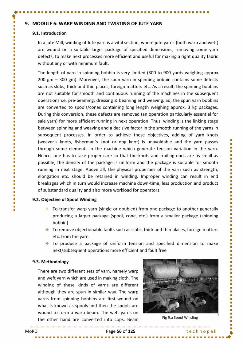
MoRD Page 56 of 125 t e c h n o p a k
9. MODULE 6: WARP WINDING AND TWISTING OF JUTE YARN
9.1. Introduction
In a jute Mill, winding of Jute yarn is a vital section, where jute yarns (both warp and weft)
are wound on a suitable larger package of specified dimensions, removing some yarn
defects, to make next processes more efficient and useful for making a right quality fabric
without any or with minimum fault.
The length of yarn in spinning bobbin is very limited (300 to 900 yards weighing approx
200 gm – 300 gm). Moreover, the spun yarn in spinning bobbin contains some defects
such as slubs, thick and thin places, foreign matters etc. As a result, the spinning bobbins
are not suitable for smooth and continuous running of the machines in the subsequent
operations i.e. pre-beaming, dressing & beaming and weaving. So, the spun yarn bobbins
are converted to spools/cones containing long length weighing approx. 3 kg packages.
During this conversion, these defects are removed (an operation particularly essential for
sale yarn) for more efficient running in next operation. Thus, winding is the linking stage
between spinning and weaving and a decisive factor in the smooth running of the yarns in
subsequent processes. In order to achieve these objectives, adding of yarn knots
(weaver`s knots, fisherman`s knot or dog knot) is unavoidable and the yarn passes
through some elements in the machine which generate tension variation in the yarn.
Hence, one has to take proper care so that the knots and trailing ends are as small as
possible, the density of the package is uniform and the package is suitable for smooth
running in next stage. Above all, the physical properties of the yarn such as strength,
elongation etc. should be retained in winding. Improper winding can result in end
breakages which in turn would increase machine down-time, less production and product
of substandard quality and also more workload for operators.
9.2. Objective of Spool Winding
To transfer warp yarn (single or doubled) from one package to another generally
producing a larger package (spool, cone, etc.) from a smaller package (spinning
bobbin)
To remove objectionable faults such as slubs, thick and thin places, foreign matters
etc. from the yarn
To produce a package of uniform tension and specified dimension to make
next/subsequent operations more efficient and fault free
9.3. Methodology
There are two different sets of yarn, namely warp
and weft yarn which are used in making cloth. The
winding of these kinds of yarns are different
although they are spun in similar way. The warp
yarns from spinning bobbins are first wound on
what is known as spools and then the spools are
wound to form a warp beam. The weft yarns on
the other hand are converted into cops. Beam Fig 9.a Spool Winding
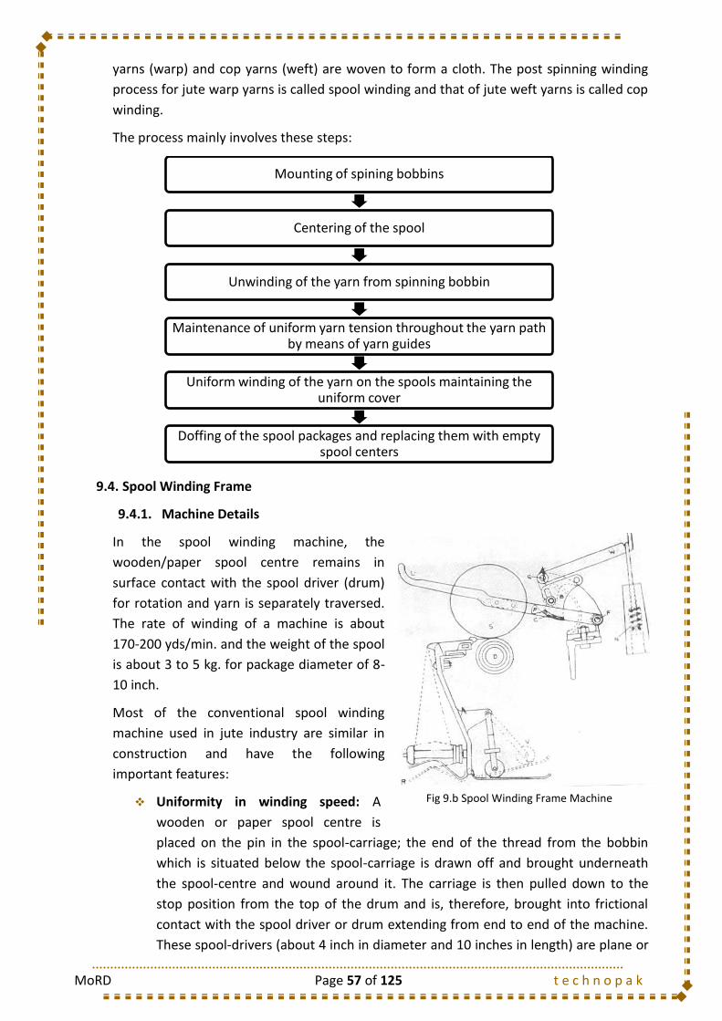
MoRD Page 57 of 125 t e c h n o p a k
yarns (warp) and cop yarns (weft) are woven to form a cloth. The post spinning winding
process for jute warp yarns is called spool winding and that of jute weft yarns is called cop
winding.
The process mainly involves these steps:
9.4. Spool Winding Frame
9.4.1. Machine Details
In the spool winding machine, the
wooden/paper spool centre remains in
surface contact with the spool driver (drum)
for rotation and yarn is separately traversed.
The rate of winding of a machine is about
170-200 yds/min. and the weight of the spool
is about 3 to 5 kg. for package diameter of 8-
10 inch.
Most of the conventional spool winding
machine used in jute industry are similar in
construction and have the following
important features:
Uniformity in winding speed: A
wooden or paper spool centre is
placed on the pin in the spool-carriage; the end of the thread from the bobbin
which is situated below the spool-carriage is drawn off and brought underneath
the spool-centre and wound around it. The carriage is then pulled down to the
stop position from the top of the drum and is, therefore, brought into frictional
contact with the spool driver or drum extending from end to end of the machine.
These spool-drivers (about 4 inch in diameter and 10 inches in length) are plane or
Mounting of spining bobbins
Centering of the spool
Unwinding of the yarn from spinning bobbin
Maintenance of uniform yarn tension throughout the yarn path by means of yarn guides
Uniform winding of the yarn on the spools maintaining the uniform cover
Doffing of the spool packages and replacing them with empty spool centers
Fig 9.b Spool Winding Frame Machine
MoRD Page 58 of 125 t e c h n o p a k
fluted and driven by pulleys of equal size and a cross-belt. These belts are endless
and made specially for this drive and cause the spool driver shafts to revolve in
one direction, namely inward.
Quick traverse of the yarn guide: The rapid traverse necessary for building the
yarn without the aid of flanges, is imparted directly by the yarn guide. All the
guides are changeable to suit different counts of yarn. The yarn guide is rigidly
fixed to the “Traverse Bar”, which is supported by and sides in “guides” or
“brackets” fixed at suitable places on the framework of the machine and this is
attached by a connecting-rod to the Traverse Lever. The Traverse Lever, fulcrumed
at the centre, imparts an equal but opposite movement to the Traverse Bar at the
opposite side of the machine. The rapid traverse motion is conveyed to the
traverse lever. A cam revolves between the anti-friction cones bolted to the
traverse levers and thus imparts necessary motion through the traverse-bars and
the yarn guides which generate the necessary quick traverse-period. The length of
the spools may be varied at will between 7 inches to 10 inches by adjusting the
studs in the slots of the traverse lever. The cam is needed to be greased as it
revolves. The traverse motion builds the yarn on the spool-centre in a criss-cross
fashion and as the “guide” moves in. it is the quickest at the end and the yarn
turns so sharply that it builds up a perfect end without the need of assistance of a
flange.
Automatic stop motion when the spool reaches the desired diameter: The spool-
carriage lever L has an inclined plane P at its end and is fulcrumed at F. The weight-
lever W, fulcrumed at Q about ¼ inches from the end which works up to the plane
P of the Carriage Lever L, has a Catch C which, when it gets over the plane-end of
the Carriage Lever Catch, at once pulls it down, thus withdrawing the spool-
carriage S from the spool-driver D and thus stops the spool at its required diameter
set. The diameter may be varied in size by raising and lowering the stud in the
bracket B and the fulcrum Q of the weight lever W. This is done by means of a set-
screw and a lock-nut. A small spring, washer and nut N on the end of the rod
carrying the weight H and entering a recess in the weight, takes off any vibration
when the weight H drops back into its original position.
Individual tension device: Spinning Bobbins are placed on pins centered beneath
each spool-driver. These bobbins are tensioned by means of a spring R and
weighted lever V. Since it is essential that the pressure should decrease as the
bobbin is exhausted, the Lever is so centered that it gradually approaches a
vertical position and reduces its pressure on the spring R as the diameter of the
bobbin decreases. Capacity of the conventional spool winding machine is 40 spools
on each side, divided into banks of 20. The machines run at about 550 revolutions
per minute, giving winding speed of about 170-220 (say 192) yds./min. with 4
inches diameter spool-drum either plane or fluted. The machines of different
makers having tensioning, cleaning and measuring devices are all built alike but
may differ in small details.
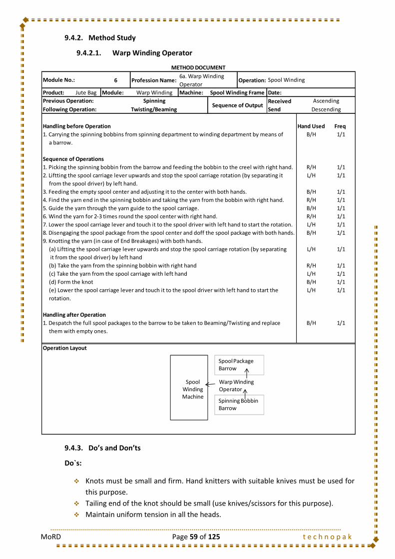
MoRD Page 59 of 125 t e c h n o p a k
9.4.2. Method Study
9.4.2.1. Warp Winding Operator
9.4.3. Do’s and Don’ts
Do`s:
Knots must be small and firm. Hand knitters with suitable knives must be used for
this purpose.
Tailing end of the knot should be small (use knives/scissors for this purpose).
Maintain uniform tension in all the heads.
6 Profession Name: Operation:
Product: Jute Bag Module: Warp Winding Machine: Date:
Received
Send
Handling before Operation Hand Used Freq
1. Carrying the spinning bobbins from spinning department to winding department by means of B/H 1/1
a barrow.
Sequence of Operations
1. Picking the spinning bobbin from the barrow and feeding the bobbin to the creel with right hand. R/H 1/1
2. Liftting the spool carriage lever upwards and stop the spool carriage rotation (by separating it L/H 1/1
from the spool driver) by left hand.
3. Feeding the empty spool center and adjusting it to the center with both hands. B/H 1/1
4. Find the yarn end in the spinning bobbin and taking the yarn from the bobbin with right hand. R/H 1/1
5. Guide the yarn through the yarn guide to the spool carriage. B/H 1/1
6. Wind the yarn for 2-3 times round the spool center with right hand. R/H 1/1
7. Lower the spool carriage lever and touch it to the spool driver with left hand to start the rotation. L/H 1/1
8. Disengaging the spool package from the spool center and doff the spool package with both hands. B/H 1/1
9. Knotting the yarn (in case of End Breakages) with both hands.
(a) Liftting the spool carriage lever upwards and stop the spool carriage rotation (by separating L/H 1/1
it from the spool driver) by left hand
R/H 1/1
L/H 1/1
B/H 1/1
L/H 1/1
rotation.
Handling after Operation
1. Despatch the full spool packages to the barrow to be taken to Beaming/Twisting and replace B/H 1/1
them with empty ones.
Operation Layout
METHOD DOCUMENT
Module No.:6a. Warp Winding
OperatorSpool Winding
Spool Winding Frame
Previous Operation: SpinningSequence of Output
Ascending
Following Operation: Twisting/Beaming Descending
(b) Take the yarn from the spinning bobbin with right hand
(c) Take the yarn from the spool carriage with left hand
(d) Form the knot
(e) Lower the spool carriage lever and touch it to the spool driver with left hand to start the
Spool Winding Machine
Warp WindingOperator
Spinning Bobbin Barrow
Spool Package Barrow
MoRD Page 60 of 125 t e c h n o p a k
Make the waste of the good yarn minimum at the time of yarn knotting due to
break or feed package change.
Remove the thick places, slubs etc. from the yarn, if visible.
Identify the defective spools (in hardness and centering) and keep them
separately.
Spools and spinning bobbins should be handled carefully. Use trolleys for spools
and spinning bobbins separately.
Release the yarn in taut condition after knotting.
Maintain the machine and its surroundings clean.
Use fully cleaned spool center.
Check whether the yarn is out of the drum-groove during winding on a grooved
drum winding machine. If so, make the yarn to pass through the groove
immediately.
Take proper precaution during change of quality and avoid mixing of bobbins and
spools. Use proper marking.
Always try to improve productivity and reduce wastage of yarns.
Maintain discipline and punctuality at the workplace.
Keep all the waste in waste bag only.
Full spools/cones should be stacked properly.
Don`ts:
Do not join yarn without proper knot.
Do not give/allow loose and/or bigger knots.
Do not allow longer trailing ends in knots.
Do not waste good yarn during knotting/removing faults.
Do not stop the spool rotation by hand, without actuation of stop motion in the
winding machine, for knotting.
Do not use defective or dirty spool centers.
Do not produce oversize or undersize spools.
Do not produce defective spools.
Do not allow variation in diameter of the spools – higher diameter will not fit in the
beaming/pre beaming creel.
Do not damage the bobbin flanges by throwing bobbins on the floors. [Bobbin
cleaners should not scratch the bobbin tubes and tops by knives during cleaning.]
Do not stop the machine more frequently than required. No drum or spindle
should remain idle unnecessarily.
Do not throw waste or any machine parts in the ground.
Do not neglect any of the systematic operations for building the spools.
Do not spit or smoke in the shed.
Do not argue or unnecessary conversation with colleagues/superiors.
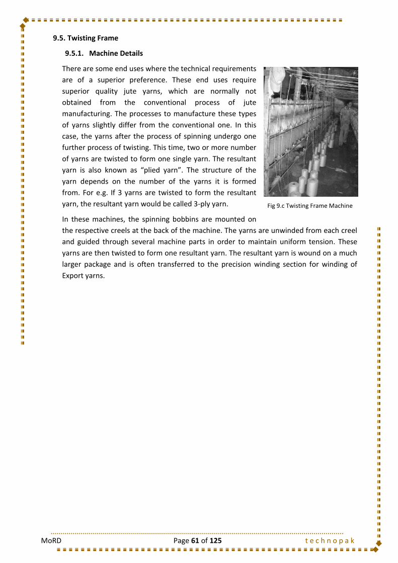
MoRD Page 61 of 125 t e c h n o p a k
9.5. Twisting Frame
9.5.1. Machine Details
There are some end uses where the technical requirements
are of a superior preference. These end uses require
superior quality jute yarns, which are normally not
obtained from the conventional process of jute
manufacturing. The processes to manufacture these types
of yarns slightly differ from the conventional one. In this
case, the yarns after the process of spinning undergo one
further process of twisting. This time, two or more number
of yarns are twisted to form one single yarn. The resultant
yarn is also known as “plied yarn”. The structure of the
yarn depends on the number of the yarns it is formed
from. For e.g. If 3 yarns are twisted to form the resultant
yarn, the resultant yarn would be called 3-ply yarn.
In these machines, the spinning bobbins are mounted on
the respective creels at the back of the machine. The yarns are unwinded from each creel
and guided through several machine parts in order to maintain uniform tension. These
yarns are then twisted to form one resultant yarn. The resultant yarn is wound on a much
larger package and is often transferred to the precision winding section for winding of
Export yarns.
Fig 9.c Twisting Frame Machine
MoRD Page 62 of 125 t e c h n o p a k
9.5.2. Method Study
9.5.2.1. Twister
9.5.1. Do’s and Don’ts
Do`s
Knots must be small and firm. Hand knitters with suitable knives must be used for
this purpose.
Tailing end of the knot should be small (use knives/scissors for this purpose).
Make the waste of the good yarn minimum at the time of yarn knotting due to
break or feed package change.
Remove the thick places, slubs etc. from the yarn, if visible.
Identify the defective Yarn Packages (in hardness and centering) and keep them
separately.
6 Profession Name: Operation:
Product: Jute Bag Module:Warp Winding
and TwistingMachine: Date:
Received
Send
Handling before Operation Hand Used Freq
1. Carrying the spinning bobbins from spinning department to winding department by means of B/H 1/1
a barrow
Sequence of Operations
1. Picking the spinning bobbin from the barrow and feeding the bobbin to the creel with right hand. R/H 1/1
2. Feeding the empty Yarn Bobbin and adjusting it with both hands. B/H 1/1
3. Find the yarn end in the spinning bobbin and taking the yarn from the bobbin with right hand. R/H 1/1
4. Guide the yarn through the yarn guide to the yarn package. B/H 1/1
5. Wind the yarn for 2-3 times round the package center with right hand. R/H 1/1
6. Start the machine. L/H 1/1
7. Doff the Yarn package with both hands. B/H 1/1
8. Knotting the yarn (in case of End Breakages) with both hands. B/H 1/1
R/H 1/1
L/H 1/1
B/H 1/1
Handling after Operation
1. Despatch the full Yarn packages to the barrow to be taken to Precision Winding Machine and B/H 1/1
replace them with empty ones.
Operation Layout
METHOD DOCUMENT
Module No.: 6b. Twister Twisting
Twisting Frame
Previous Operation: Spool WindingSequence of Output
Ascending
Following Operation: Precision Winding Descending
(a) Take the yarn from the spinning bobbin with right hand
(b) Take the yarn from the package (already in running condition) with left hand
(c) Form the knot
Twisting Frame
TwisterSpinning Bobbin Barrow
Creeling Zone
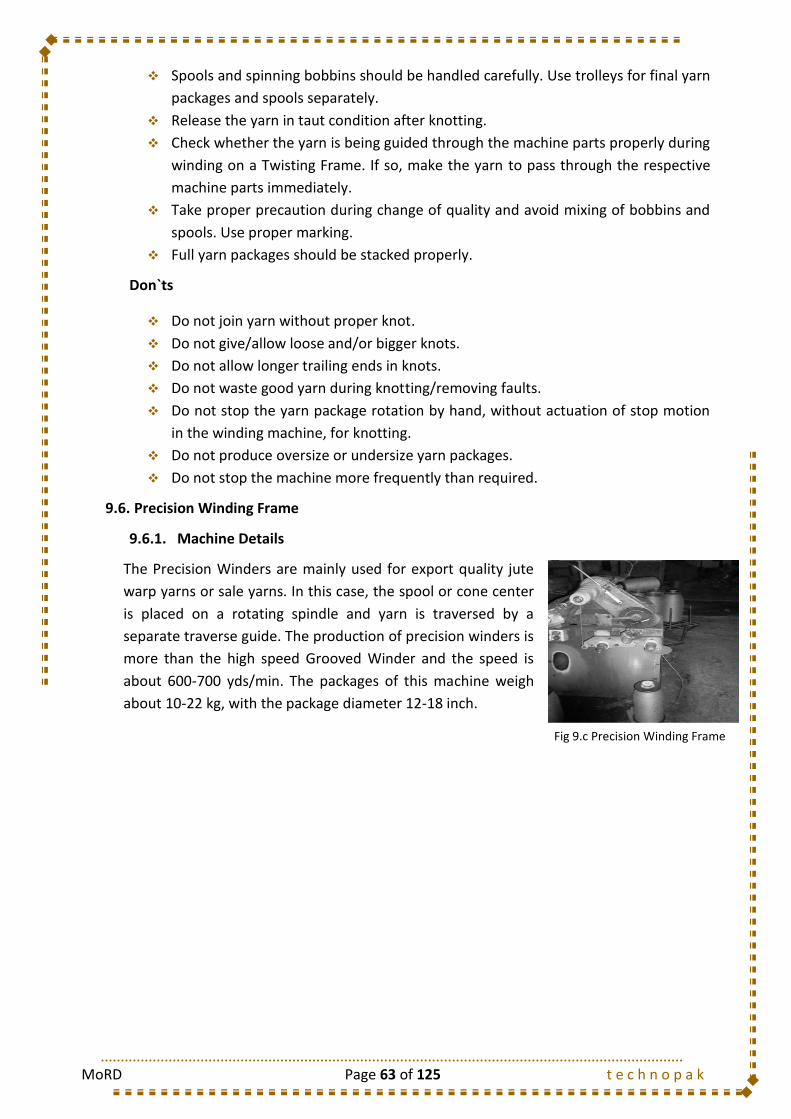
MoRD Page 63 of 125 t e c h n o p a k
Spools and spinning bobbins should be handled carefully. Use trolleys for final yarn
packages and spools separately.
Release the yarn in taut condition after knotting.
Check whether the yarn is being guided through the machine parts properly during
winding on a Twisting Frame. If so, make the yarn to pass through the respective
machine parts immediately.
Take proper precaution during change of quality and avoid mixing of bobbins and
spools. Use proper marking.
Full yarn packages should be stacked properly.
Don`ts
Do not join yarn without proper knot.
Do not give/allow loose and/or bigger knots.
Do not allow longer trailing ends in knots.
Do not waste good yarn during knotting/removing faults.
Do not stop the yarn package rotation by hand, without actuation of stop motion
in the winding machine, for knotting.
Do not produce oversize or undersize yarn packages.
Do not stop the machine more frequently than required.
9.6. Precision Winding Frame
9.6.1. Machine Details
The Precision Winders are mainly used for export quality jute
warp yarns or sale yarns. In this case, the spool or cone center
is placed on a rotating spindle and yarn is traversed by a
separate traverse guide. The production of precision winders is
more than the high speed Grooved Winder and the speed is
about 600-700 yds/min. The packages of this machine weigh
about 10-22 kg, with the package diameter 12-18 inch.
Fig 9.c Precision Winding Frame
MoRD Page 64 of 125 t e c h n o p a k
9.6.2. Method Study
9.6.2.1. Precision Winding Operator
9.6.3. Do’s and Don’ts
Do`s
Knots must be small and firm. Hand knitters with suitable knives must be used for
this purpose.
6 Profession Name: Operation:
Product: Jute Yarn Module:Warp Winding
and TwistingMachine: Date:
Received
Send
Handling before Operation Hand Used Freq
1. Carrying the spinning bobbins from spinning department to winding department by means of B/H 1/1
a barrow
Sequence of Operations
1. Picking the spinning bobbin from the barrow and feeding the bobbin to the creel with right hand. R/H 1/1
2. Moving the Export yarn package carriage lever sideways and stop the carriage rotation (by L/H 1/1
separating it from the driver) by left hand.
3. Feeding the empty feed package center and adjusting it to the center with both hands. B/H 1/1
4. Find the yarn end in the spinning bobbin and taking the yarn from the bobbin with right hand. R/H 1/1
5. Guide the yarn through the yarn guide to the Export yarn package. B/H 1/1
6. Wind the yarn for 2-3 times round the package center with right hand. R/H 1/1
7. Move the package carriage lever sideways (reverse direction)and touch it to the package driver L/H 1/1
with left hand to start the rotation.
8. Disengaging the package from the package center and doff the Export Yarn package with both B/H 1/1
hands.
9. Knotting the yarn (in case of End Breakages) with both hands.
(a) Move the Export yarn package carriage lever sideways and stop the carriage rotation (by L/H 1/1
separating it from the driver) by left hand.
R/H 1/1
L/H 1/1
B/H 1/1
L/H 1/1
driver with left hand to start the rotation.
Handling after Operation
1. Despatch the full packages to the barrow to be taken to Beaming/Packing and replace them B/H 1/1
with empty ones.
Operation Layout
METHOD DOCUMENT
Module No.:6c. Precision Winding
OperatorPrecision Winding
Precision Winding
Frame
Previous Operation: TwistingSequence of Output
Ascending
Following Operation: Beaming/Yarn Packing Descending
(b) Take the yarn from the spinning bobbin with right hand.
(c) Take the yarn from the package with left hand.
(d) Form the knot.
(e) Move the package carriage lever sideways (reverse direction)and touch it to the package
Precision Winding Machine
Precision Winding Operator
Spinning Bobbin Barrow
Yarn Package Barrow
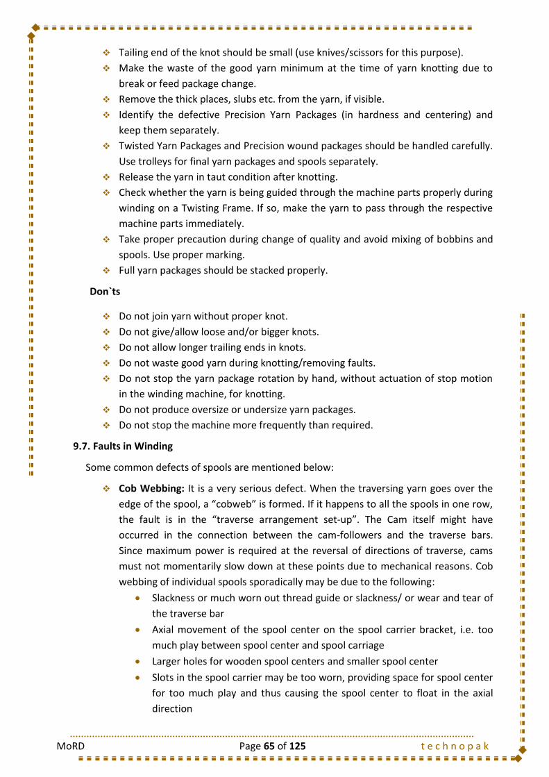
MoRD Page 65 of 125 t e c h n o p a k
Tailing end of the knot should be small (use knives/scissors for this purpose).
Make the waste of the good yarn minimum at the time of yarn knotting due to
break or feed package change.
Remove the thick places, slubs etc. from the yarn, if visible.
Identify the defective Precision Yarn Packages (in hardness and centering) and
keep them separately.
Twisted Yarn Packages and Precision wound packages should be handled carefully.
Use trolleys for final yarn packages and spools separately.
Release the yarn in taut condition after knotting.
Check whether the yarn is being guided through the machine parts properly during
winding on a Twisting Frame. If so, make the yarn to pass through the respective
machine parts immediately.
Take proper precaution during change of quality and avoid mixing of bobbins and
spools. Use proper marking.
Full yarn packages should be stacked properly.
Don`ts
Do not join yarn without proper knot.
Do not give/allow loose and/or bigger knots.
Do not allow longer trailing ends in knots.
Do not waste good yarn during knotting/removing faults.
Do not stop the yarn package rotation by hand, without actuation of stop motion
in the winding machine, for knotting.
Do not produce oversize or undersize yarn packages.
Do not stop the machine more frequently than required.
9.7. Faults in Winding
Some common defects of spools are mentioned below:
Cob Webbing: It is a very serious defect. When the traversing yarn goes over the
edge of the spool, a “cobweb” is formed. If it happens to all the spools in one row,
the fault is in the “traverse arrangement set-up”. The Cam itself might have
occurred in the connection between the cam-followers and the traverse bars.
Since maximum power is required at the reversal of directions of traverse, cams
must not momentarily slow down at these points due to mechanical reasons. Cob
webbing of individual spools sporadically may be due to the following:
Slackness or much worn out thread guide or slackness/ or wear and tear of
the traverse bar
Axial movement of the spool center on the spool carrier bracket, i.e. too
much play between spool center and spool carriage
Larger holes for wooden spool centers and smaller spool center
Slots in the spool carrier may be too worn, providing space for spool center
for too much play and thus causing the spool center to float in the axial
direction
MoRD Page 66 of 125 t e c h n o p a k
Improper fitting of the spool center
Slack or worn out yarn guides
Bulging Ends: It is due to insufficient yarn tension. Causes may be:
Defective tensioning device, causing variation in winding tension
“Sticking” or irregular movement of the spool carrier bracket as the spool
builds up
Irregular or varied pressure on the spools
Soft Package:
It happens mainly due to low winding tension
It can also be for choice of lower dead weight than required
Wrong Centering:
Improper setting of the traverse bar/thread guide
Improper length of spool center may cause this defect.
9.8. Hard Wastes and its Control
Some amount of waste in winding is unavoidable, but
a reduction of small percentage of waste for good
yarn can save a huge amount of rupees per year in a
mill. So the amount of hard waste at winding should
be as low as possible.
For minimum waste reduction in winding, the
following points must be followed:
Spinning bobbins must be fully consumed /
emptied.
Length of yarn removed for eliminating slubs/thick or thin places etc. should be
also as small as possible. Unnecessary good yarn shall not be removed, during
removing yarn faults.
Length of tail ends removed after knotting should be as small as possible.
Defective or faulty spool packages should not be produced.
Yarn should be taken out from the dirty bobbin with care, so that good yarn shall
not be allowed to go to waste.
Empty spinning bobbins during transportation should not come in contact with oil,
grease etc.
Spools produced should be stacked properly with care and proper identification
mark of quality.
Unnecessary good yarn shall not be allowed to remove or to go as waste, while
repairing a defective spool package or removing a fault from feed package.
Always use waste bag for keeping yarn waste.
There shall not be any scratch or cut mark or deposition dirts etc. on the empty
bobbin particularly near the flanges.
Fig 9.d Waste Spools

MoRD Page 67 of 125 t e c h n o p a k
9.9. Types of Mazdoor
S. No. Mazdoor Type Job Description
1 Spool Mazdoor Carrying the Spool packages from Winding Department to Twisting/Beaming Department
9.10. Training Gantt Chart
Training Days Required
Class Room Training Shop Floor Training
5 Days 9 Days
1 2 3 4 5
9.1
9.2
9.3
9.4
9.4.1
9.4.2
9.4.2.1 Warp Winding Operator
9.4.3
9.5
9.5.1
9.5.2
9.4.2.1 Precision Winding Operator
9.5.3
9.6
9.5.1
9.5.2
9.4.2.1 Twister
9.5.3
9.7
9.8
9.9
1 2 3 4 5 6 7 8 9
9.1
9.2
9.3
9.4
9.4.1
9.4.2
9.4.2.1 Warp Winding Operator
9.4.3
9.5
9.5.1
9.5.2
9.4.2.1 Precision Winding Operator
9.5.3
9.6
9.5.1
9.5.2
9.4.2.1 Twister
9.5.3
9.7
9.8
9.9 Mazdoor Activities
Method Study
Do`s and Don`ts
Faults in Winding
Hard Wastes and its Control
I. CLASSROOM TRAINING
Introduction
Objectives of Spool Winding
Methodology
TWISITNG FRAME
Do`s and Don`ts
TWISITNG FRAME
Machine Details
Machine Details
Do`s and Don`ts
Machine Details
Method Study
Do`s and Don`ts
PRECISION WINDING FRAME
Method Study
MODULE 6 : WARP WINDING AND TWISTING
II. SHOP-FLOOR TRAINING
Introduction
Objectives of Spool Winding
Methodology
SPOOL WINDING FRAME
Method Study
Do`s and Don`ts
PRECISION WINDING FRAME
Machine Details
Machine Details
Method Study
Do`s and Don`ts
Types of Mazdoor
SPOOL WINDING FRAME
Method Study
Machine Details
Faults in Winding
Hard Wastes and its Control
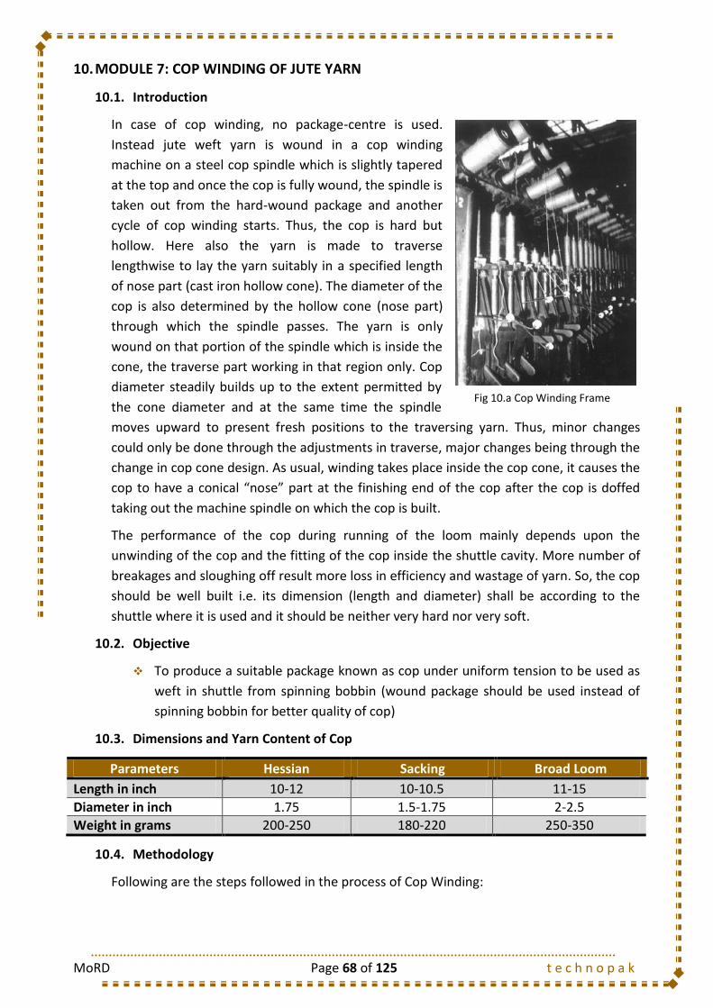
MoRD Page 68 of 125 t e c h n o p a k
10. MODULE 7: COP WINDING OF JUTE YARN
10.1. Introduction
In case of cop winding, no package-centre is used.
Instead jute weft yarn is wound in a cop winding
machine on a steel cop spindle which is slightly tapered
at the top and once the cop is fully wound, the spindle is
taken out from the hard-wound package and another
cycle of cop winding starts. Thus, the cop is hard but
hollow. Here also the yarn is made to traverse
lengthwise to lay the yarn suitably in a specified length
of nose part (cast iron hollow cone). The diameter of the
cop is also determined by the hollow cone (nose part)
through which the spindle passes. The yarn is only
wound on that portion of the spindle which is inside the
cone, the traverse part working in that region only. Cop
diameter steadily builds up to the extent permitted by
the cone diameter and at the same time the spindle
moves upward to present fresh positions to the traversing yarn. Thus, minor changes
could only be done through the adjustments in traverse, major changes being through the
change in cop cone design. As usual, winding takes place inside the cop cone, it causes the
cop to have a conical “nose” part at the finishing end of the cop after the cop is doffed
taking out the machine spindle on which the cop is built.
The performance of the cop during running of the loom mainly depends upon the
unwinding of the cop and the fitting of the cop inside the shuttle cavity. More number of
breakages and sloughing off result more loss in efficiency and wastage of yarn. So, the cop
should be well built i.e. its dimension (length and diameter) shall be according to the
shuttle where it is used and it should be neither very hard nor very soft.
10.2. Objective
To produce a suitable package known as cop under uniform tension to be used as
weft in shuttle from spinning bobbin (wound package should be used instead of
spinning bobbin for better quality of cop)
10.3. Dimensions and Yarn Content of Cop
Parameters Hessian Sacking Broad Loom
Length in inch 10-12 10-10.5 11-15
Diameter in inch 1.75 1.5-1.75 2-2.5
Weight in grams 200-250 180-220 250-350
10.4. Methodology
Following are the steps followed in the process of Cop Winding:
Fig 10.a Cop Winding Frame
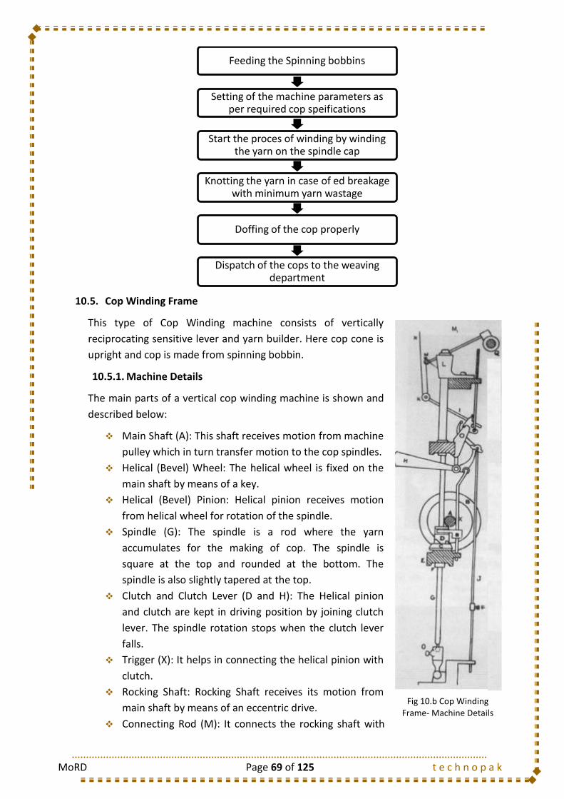
MoRD Page 69 of 125 t e c h n o p a k
10.5. Cop Winding Frame
This type of Cop Winding machine consists of vertically
reciprocating sensitive lever and yarn builder. Here cop cone is
upright and cop is made from spinning bobbin.
10.5.1. Machine Details
The main parts of a vertical cop winding machine is shown and
described below:
Main Shaft (A): This shaft receives motion from machine
pulley which in turn transfer motion to the cop spindles.
Helical (Bevel) Wheel: The helical wheel is fixed on the
main shaft by means of a key.
Helical (Bevel) Pinion: Helical pinion receives motion
from helical wheel for rotation of the spindle.
Spindle (G): The spindle is a rod where the yarn
accumulates for the making of cop. The spindle is
square at the top and rounded at the bottom. The
spindle is also slightly tapered at the top.
Clutch and Clutch Lever (D and H): The Helical pinion
and clutch are kept in driving position by joining clutch
lever. The spindle rotation stops when the clutch lever
falls.
Trigger (X): It helps in connecting the helical pinion with
clutch.
Rocking Shaft: Rocking Shaft receives its motion from
main shaft by means of an eccentric drive.
Connecting Rod (M): It connects the rocking shaft with
Feeding the Spinning bobbins
Setting of the machine parameters as per required cop speifications
Start the proces of winding by winding the yarn on the spindle cap
Knotting the yarn in case of ed breakage with minimum yarn wastage
Doffing of the cop properly
Dispatch of the cops to the weaving department
Fig 10.b Cop Winding Frame- Machine Details

MoRD Page 70 of 125 t e c h n o p a k
the yarn builder for transmitting the motion from the rocking shaft to the yarn
builder.
Yarn Builder (N): It is responsible for building up the yarn into the cop.
Sensitive Lever (I): Machine running is sensed by it. It is raised upward during
starting of the machine.
Porcelain Guide (K): It is attached at one end of the sensitive lever. It gives support
to the yarn and maintains tension on the yarn.
Collar (P): It is fitted in the stop rod. It releases the trigger when the footstep
bracket touches it after winding of desired length of cop.
Cop cone (L): The nose of the cop grows in the cop cone. The diameter of the cop
is determined by the angle of the cop cone and the distance travelled by the yarn
builder.
Lock nuts (S and S1): Lock nuts are mounted on the threaded portion on top of the
eccentric shaft. Diameter of the cop cone can be changed by the movement of lock
nuts along the length of the bracket.
Spindle Cap: Spindle cap is loosely mounted on the thread of top of the spindle. It
has a good relation with spindle rotation. If the spindle rotates the spindle cap
automatically helps in making cops with pre determined cop length and makes the
yarn end to emerge through the hole at cop end. During building of the cop, the tip
of the yarn is held tightly at the top of the spindle cap so that the final package
becomes hard sufficiently.
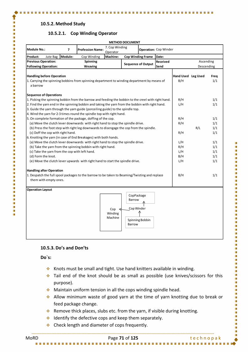
MoRD Page 71 of 125 t e c h n o p a k
10.5.2. Method Study
10.5.2.1. Cop Winding Operator
10.5.3. Do’s and Don’ts
Do`s:
Knots must be small and tight. Use hand knitters available in winding.
Tail end of the knot should be as small as possible (use knives/scissors for this
purpose).
Maintain uniform tension in all the cops winding spindle head.
Allow minimum waste of good yarn at the time of yarn knotting due to break or
feed package change.
Remove thick places, slubs etc. from the yarn, if visible during knotting.
Identify the defective cops and keep them separately.
Check length and diameter of cops frequently.
7 Profession Name: Operation:
Product: Jute Bag Module: Cop Winding Machine: Date:
Received
Send
Handling before Operation Hand Used Leg Used Freq
1. Carrying the spinning bobbins from spinning department to winding department by means of B/H 1/1
a barrow
Sequence of Operations
1. Picking the spinning bobbin from the barrow and feeding the bobbin to the creel with right hand. R/H 1/1
2. Find the yarn end in the spinning bobbin and taking the yarn from the bobbin with right hand. L/H 1/1
3. Guide the yarn through the yarn guide (porceiling guide) to the spindle top.
4. Wind the yarn for 2-3 times round the spindle top with right hand.
5. On complete formation of the package, doffing of the cop. R/H 1/1
(a) Move the clutch lever downwards with right hand to stop the spindle drive. R/H 1/1
(b) Press the foot step with right leg downwards to disengage the cop from the spindle. R/L 1/1
(c) Doff the cop with right hand. R/H 1/1
6. Knotting the yarn (in case of End Breakages) with both hands.
(a) Move the clutch lever downwards with right hand to stop the spindle drive. L/H 1/1
R/H 1/1
L/H 1/1
B/H 1/1
L/H 1/1
Handling after Operation
1. Despatch the full spool packages to the barrow to be taken to Beaming/Twisting and replace B/H 1/1
them with empty ones.
Operation Layout
METHOD DOCUMENT
Module No.:7. Cop Winding
OperatorCop Winder
Cop Winding Frame
Previous Operation: SpinningSequence of Output
Ascending
Following Operation: Weaving Descending
(b) Take the yarn from the spinning bobbin with right hand.
(c) Take the yarn from the cop with left hand.
(d) Form the knot.
(e) Move the clutch lever upwards with right hand to start the spindle drive.
Cop Winding Machine
Cop Winder
Spinning Bobbin Barrow
CopPackage Barrow
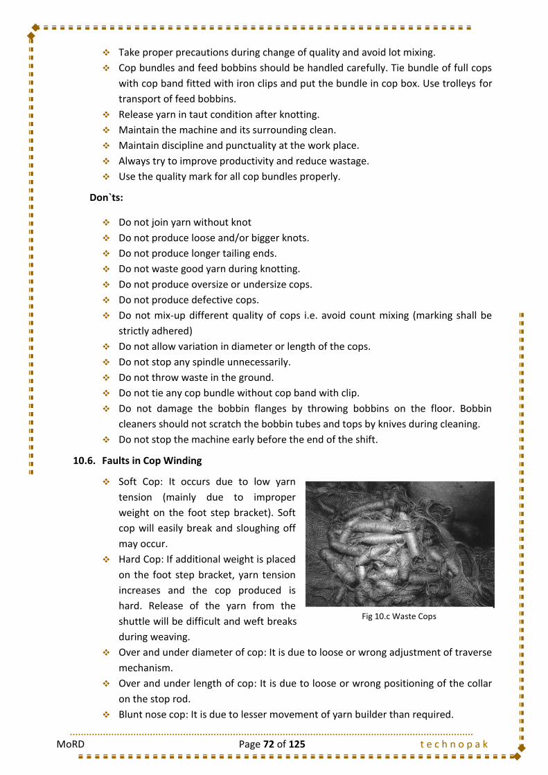
MoRD Page 72 of 125 t e c h n o p a k
Take proper precautions during change of quality and avoid lot mixing.
Cop bundles and feed bobbins should be handled carefully. Tie bundle of full cops
with cop band fitted with iron clips and put the bundle in cop box. Use trolleys for
transport of feed bobbins.
Release yarn in taut condition after knotting.
Maintain the machine and its surrounding clean.
Maintain discipline and punctuality at the work place.
Always try to improve productivity and reduce wastage.
Use the quality mark for all cop bundles properly.
Don`ts:
Do not join yarn without knot
Do not produce loose and/or bigger knots.
Do not produce longer tailing ends.
Do not waste good yarn during knotting.
Do not produce oversize or undersize cops.
Do not produce defective cops.
Do not mix-up different quality of cops i.e. avoid count mixing (marking shall be
strictly adhered)
Do not allow variation in diameter or length of the cops.
Do not stop any spindle unnecessarily.
Do not throw waste in the ground.
Do not tie any cop bundle without cop band with clip.
Do not damage the bobbin flanges by throwing bobbins on the floor. Bobbin
cleaners should not scratch the bobbin tubes and tops by knives during cleaning.
Do not stop the machine early before the end of the shift.
10.6. Faults in Cop Winding
Soft Cop: It occurs due to low yarn
tension (mainly due to improper
weight on the foot step bracket). Soft
cop will easily break and sloughing off
may occur.
Hard Cop: If additional weight is placed
on the foot step bracket, yarn tension
increases and the cop produced is
hard. Release of the yarn from the
shuttle will be difficult and weft breaks
during weaving.
Over and under diameter of cop: It is due to loose or wrong adjustment of traverse
mechanism.
Over and under length of cop: It is due to loose or wrong positioning of the collar
on the stop rod.
Blunt nose cop: It is due to lesser movement of yarn builder than required.
Fig 10.c Waste Cops

MoRD Page 73 of 125 t e c h n o p a k
Bullet nose cop: It is due to greater movement of the yarn builder than required.
Missing end: It occurs due to – (i) yarn breakage at the contact point of the spindle,
and (ii) loose knot.
Irregular cop: It is produced due to worn out cop cone.
10.7. Hard Wastes and its Control
Some amount of waste in cop winding is unavoidable, but a reduction of small percentage
of waste of good yarn can save a huge amount of rupees per year in a mill. So the amount
of hard waste at cop winding should be as low as possible. For minimum waste in cop
winding, the following points must be followed:
All feed bobbins must be fully consumed.
Length of tail ends removed after knotting should be as small as possible.
Length of yarn removed for eliminating slubs/thick or thin places etc. should be as
small as possible.
Defective or faulty cops should not be produced.
Cops shall be stacked and transported with care.
Feed bobbins full or empty and cops should not come in contact with oil, grease,
etc.
Unnecessary good yarn shall not be wasted.
Waste bags should be used for keeping yarn waste.
10.8. Productivity: Control Measures
Control of productivity at cop winding will require estimation of optimum spindle
allocation to a winder and the expected efficiency and productivity at that allocation. This
depends on the following:
End breakage rate.
Winding speed.
Yarn content per cop
Condition of spinning bobbins.
Workload on winder
Miscellaneous machine stops
Production in weight of any cop winding machine depends on the following:
Winding speed (yds/min)
Efficiency (%)
Number of spindles in the machine
Running count of the yarn
10.9. Types of Mazdoor
S. No. Mazdoor Type Job Description
1 Cop Mazdoor Carrying the Cop packages from Winding Department to Weaving Department

MoRD Page 74 of 125 t e c h n o p a k
10.10. Training Gantt Chart
Training Days Required
Class Room Training Shop Floor Training
5 Days 9 Days
1 2 3 4 5
10.1 Introduction
10.2 Objective
10.3 Dimensions and Yarn Content of Cop
10.4 Methodology
10.5 COP WINDING FRAME
10.4.1 Machine Details
10.4.2 Method Study
10.4.2.1 Cop Winding Operator
10.4.3 Do`s and Don`ts
10.6 Faults in Winding
10.7 Hard Wastes and its Control
10.8 Productivity: Control Measures
10.9 Types of Mazdoor
1 2 3 4 5 6 7 8 9 10 11 12 13 14 15
10.1 Introduction
10.2 Objective
10.3 Dimensions and Yarn Content of Cop
10.4 Methodology
10.5 COP WINDING FRAME
10.4.1 Machine Details
10.4.2 Method Study
10.4.2.1 Cop Winding Operator
10.4.3 Do`s and Don`ts
10.6 Faults in Winding
10.7 Hard Wastes and its Control
10.8 Productivity: Control Measures
10.9
MODULE 7 : COP WINDING
Mazdoor Activities
II. SHOP-FLOOR TRAINING
I. CLASSROOM TRAINING

MoRD Page 75 of 125 t e c h n o p a k
11. MODULE 8: SIZING AND BEAMING OF JUTE YARN
11.1. Introduction
Two sets of yarns namely warp and weft yarns; are necessary for making a cloth. Both
warp and weft yarns need specific preparation before those are placed in a loom for
weaving. Desired length of warp yarns (from spools/cones) in a specified numbers are
wound on a beam tube called warp beam to make it convenient to place it at the back of
loom to make a fabric of specified design and construction by weaving. Weaving is a
process of interlacement of two sets of yarns namely warps (along the length of fabric)
and weft (across the width of the fabric) placed at right angles to each other.
Warp yarns are supplied to the weaving machine (i.e. loom) in a sheet form wrapped on
an iron tube centre with flanges called weaver`s beam or warp beam. This sheet of warp
yarns has to bear the weaving tension as well as frictional contacts and repeated abrasion,
warp yarns during the weaving cycle. Therefore, to withstand the weaving tension and
repeated abrasion, warp yarns during preparation of weaver`s beam, are coated with
paste of some gummy or adhesive size materials. This coating helps in laying the surface
hairs of warp yarns and improves its frictional resistance and ability to withstand weaving
tension. Thus it reduces warp-yarn breakages in weaving and increases weaving efficiency.
Thus, to fulfill the weaving requirements and to obtain optimum level of weaving
production, sizing/ dressing of warp yarns is very important before the warp yarns are
wound on an empty beam. A good quality weaver`s beam is essential for minimum warp
breakage during weaving.
11.2. Objective
To produce a sheet of warp yarns from large number of individual spools/cones
according to runners required in cloth.
To coat the warp yarns with size paste to improve the weaveability of the warp
(weavability means the ability of the warp to withstand the stress-strain and
abrasion, the warp is subjected to in every loom cycle)
11.3. Methodology
11.3.1. Creeling of yarn bobbins
After the warp winding process, the spool packages are
converted into a much larger package or rather a “beam”.
The spools are mounted respectively in respective creels. The
yarn is unwinded from each spool and this yarn is wound on a
beam forming what is known as warp beam. This process of
mounting of the spool packages in respective slots for the
purpose of unwinding is known as Creeling.
Fig 11.a Creeling
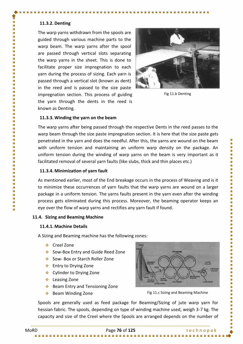
MoRD Page 76 of 125 t e c h n o p a k
11.3.2. Denting
The warp yarns withdrawn from the spools are
guided through various machine parts to the
warp beam. The warp yarns after the spool
are passed through vertical slots separating
the warp yarns in the sheet. This is done to
facilitate proper size impregnation to each
yarn during the process of sizing. Each yarn is
passed through a vertical slot (known as dent)
in the reed and is passed to the size paste
impregnation section. This process of guiding
the yarn through the dents in the reed is
known as Denting.
11.3.3. Winding the yarn on the beam
The warp yarns after being passed through the respective Dents in the reed passes to the
warp beam through the size paste impregnation section. It is here that the size paste gets
penetrated in the yarn and does the needful. After this, the yarns are wound on the beam
with uniform tension and maintaining an uniform warp density on the package. An
uniform tension during the winding of warp yarns on the beam is very important as it
facilitated removal of several yarn faults (like slubs, thick and thin places etc.)
11.3.4. Minimization of yarn fault
As mentioned earlier, most of the End breakage occurs in the process of Weaving and is it
to minimize these occurrences of yarn faults that the warp yarns are wound on a larger
package in a uniform tension. The yarns faults present in the yarn even after the winding
process gets eliminated during this process. Moreover, the beaming operator keeps an
eye over the flow of warp yarns and rectifies any yarn fault if found.
11.4. Sizing and Beaming Machine
11.4.1. Machine Details
A Sizing and Beaming machine has the following zones:
Creel Zone
Sow-Box Entry and Guide Reed Zone
Sow- Box or Starch Roller Zone
Entry to Drying Zone
Cylinder to Drying Zone
Leasing Zone
Beam Entry and Tensioning Zone
Beam Winding Zone
Spools are generally used as feed package for Beaming/Sizing of jute warp yarn for
hessian fabric. The spools, depending on type of winding machine used, weigh 3-7 kg. The
capacity and size of the Creel where the Spools are arranged depends on the number of
Fig 11.c Sizing and Beaming Machine
Fig 11.b Denting
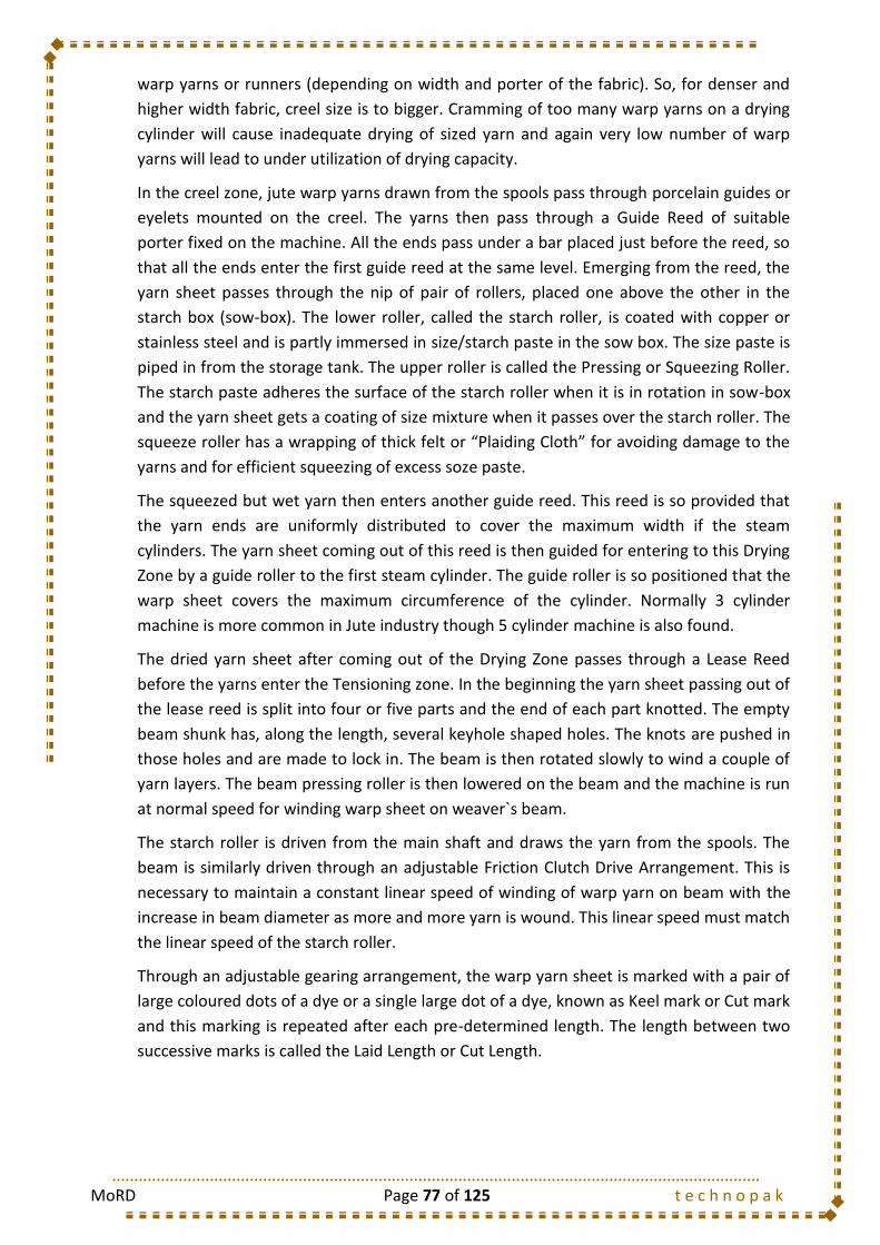
MoRD Page 77 of 125 t e c h n o p a k
warp yarns or runners (depending on width and porter of the fabric). So, for denser and
higher width fabric, creel size is to bigger. Cramming of too many warp yarns on a drying
cylinder will cause inadequate drying of sized yarn and again very low number of warp
yarns will lead to under utilization of drying capacity.
In the creel zone, jute warp yarns drawn from the spools pass through porcelain guides or
eyelets mounted on the creel. The yarns then pass through a Guide Reed of suitable
porter fixed on the machine. All the ends pass under a bar placed just before the reed, so
that all the ends enter the first guide reed at the same level. Emerging from the reed, the
yarn sheet passes through the nip of pair of rollers, placed one above the other in the
starch box (sow-box). The lower roller, called the starch roller, is coated with copper or
stainless steel and is partly immersed in size/starch paste in the sow box. The size paste is
piped in from the storage tank. The upper roller is called the Pressing or Squeezing Roller.
The starch paste adheres the surface of the starch roller when it is in rotation in sow-box
and the yarn sheet gets a coating of size mixture when it passes over the starch roller. The
squeeze roller has a wrapping of thick felt or “Plaiding Cloth” for avoiding damage to the
yarns and for efficient squeezing of excess soze paste.
The squeezed but wet yarn then enters another guide reed. This reed is so provided that
the yarn ends are uniformly distributed to cover the maximum width if the steam
cylinders. The yarn sheet coming out of this reed is then guided for entering to this Drying
Zone by a guide roller to the first steam cylinder. The guide roller is so positioned that the
warp sheet covers the maximum circumference of the cylinder. Normally 3 cylinder
machine is more common in Jute industry though 5 cylinder machine is also found.
The dried yarn sheet after coming out of the Drying Zone passes through a Lease Reed
before the yarns enter the Tensioning zone. In the beginning the yarn sheet passing out of
the lease reed is split into four or five parts and the end of each part knotted. The empty
beam shunk has, along the length, several keyhole shaped holes. The knots are pushed in
those holes and are made to lock in. The beam is then rotated slowly to wind a couple of
yarn layers. The beam pressing roller is then lowered on the beam and the machine is run
at normal speed for winding warp sheet on weaver`s beam.
The starch roller is driven from the main shaft and draws the yarn from the spools. The
beam is similarly driven through an adjustable Friction Clutch Drive Arrangement. This is
necessary to maintain a constant linear speed of winding of warp yarn on beam with the
increase in beam diameter as more and more yarn is wound. This linear speed must match
the linear speed of the starch roller.
Through an adjustable gearing arrangement, the warp yarn sheet is marked with a pair of
large coloured dots of a dye or a single large dot of a dye, known as Keel mark or Cut mark
and this marking is repeated after each pre-determined length. The length between two
successive marks is called the Laid Length or Cut Length.

MoRD Page 78 of 125 t e c h n o p a k
11.4.2. Method Study
11.4.2.1. Feeder
8 Profession Name: Operation:
Product: Jute Bag Module: Sizing & Beaming Machine: Date:
Received
Send
Handling before Operation Hand Used Freq
1. Carrying the spool packages from winding department to Beaming department by means of B/H 1/1
a barrow
Sequence of Operations
1. Picking the spool packages from the barrow and feeding the packages to the creel with right hand. R/H 1/1
2. Find the yarn end in the spool package, take the yarn and pass the yarn with right hand through R/H 1/1
the porceilin guide/eyelet mounted on creel.
3. Pass the yarn through the dents of the Guide Reed and following machine parts with both hands B/H 1/1
(only if the process parameters are changes)
4. Knotting the yarn (after complete exhaustion of spool packages or due to any end breakage) B/H 1/1
with both hands.
R/H 1/1
L/H 1/1
B/H 1/1
Operation Layout
METHOD DOCUMENT
Module No.: 8a. Feeder Sizing & Beaming
Sizing and Beaming
Machine
Previous Operation: Spool WindingSequence of Output
Ascending
Following Operation: Beam Receiving Descending
(a) Take the yarn from the newly fed Spool Package with right hand
(b) Take the yarn already in motion in the motion
(c) Form the knot
SpoolPckageBarrow
Creeling Zone Beaming Machine
Feeder
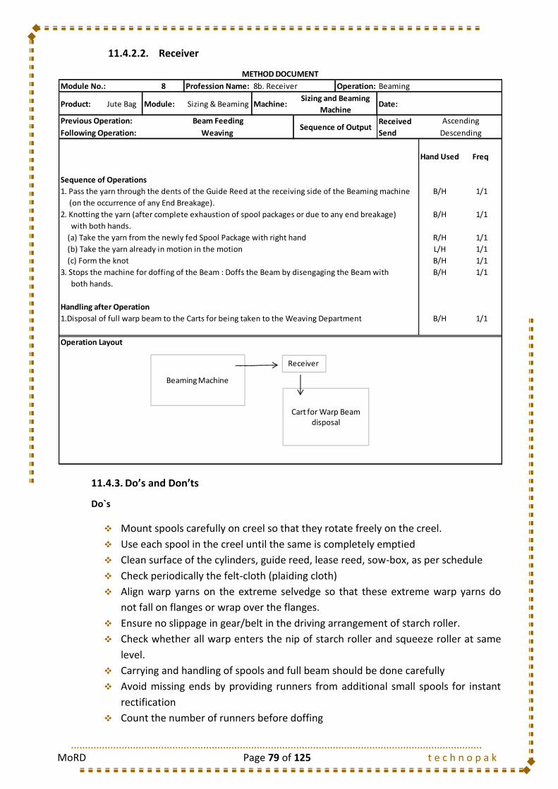
MoRD Page 79 of 125 t e c h n o p a k
11.4.2.2. Receiver
11.4.3. Do’s and Don’ts
Do`s
Mount spools carefully on creel so that they rotate freely on the creel.
Use each spool in the creel until the same is completely emptied
Clean surface of the cylinders, guide reed, lease reed, sow-box, as per schedule
Check periodically the felt-cloth (plaiding cloth)
Align warp yarns on the extreme selvedge so that these extreme warp yarns do
not fall on flanges or wrap over the flanges.
Ensure no slippage in gear/belt in the driving arrangement of starch roller.
Check whether all warp enters the nip of starch roller and squeeze roller at same
level.
Carrying and handling of spools and full beam should be done carefully
Avoid missing ends by providing runners from additional small spools for instant
rectification
Count the number of runners before doffing
8 Profession Name: Operation:
Product: Jute Bag Module: Sizing & Beaming Machine: Date:
Received
Send
Hand Used Freq
Sequence of Operations
1. Pass the yarn through the dents of the Guide Reed at the receiving side of the Beaming machine B/H 1/1
(on the occurrence of any End Breakage).
2. Knotting the yarn (after complete exhaustion of spool packages or due to any end breakage) B/H 1/1
with both hands.
R/H 1/1
L/H 1/1
B/H 1/1
3. Stops the machine for doffing of the Beam : Doffs the Beam by disengaging the Beam with B/H 1/1
both hands.
Handling after Operation
1.Disposal of full warp beam to the Carts for being taken to the Weaving Department B/H 1/1
Operation Layout
METHOD DOCUMENT
Module No.: 8b. Receiver Beaming
Sizing and Beaming
Machine
Previous Operation: Beam FeedingSequence of Output
Ascending
Following Operation: Weaving Descending
(a) Take the yarn from the newly fed Spool Package with right hand
(b) Take the yarn already in motion in the motion
(c) Form the knot
Cart for Warp Beam disposal
Beaming Machine
Receiver

MoRD Page 80 of 125 t e c h n o p a k
Tighten the beam flanges properly with double bolts, before mounting the empty
beam on the machine
Spread the warp yarns uniformly
Don`ts
Don`t throw empty spool centres here and there
Don`t reject spool centres with any layer of yarns remaining
Don`t allow deposition of short fibre on the cylinder due to adherence of sized
loose fibers coming out of yarns
Don`t use spoiled and old size paste without checking its quality
Don`t allow missing/crossed/entangled ends
Don`t allow high level of moisture on the beam
Don`t allow sticking of yarns to each other
11.5. Waste Control in Sizing and Beaming Machine
There are three types of wastages in the Sizing/Beaming Department viz. wastage of
yarns, size paste and steam. Yarns are wasted mainly due to taking out of spool centres
which are not completely emptied. This leads to winding of one quality of yarn on the
spool centre containing small amount of previous yarn of different quality, thus causing a
quality mix-up, and wastage. A good quality spool prepared in winding department and
using of the same until completely emptied during beam preparation, can reduce the yarn
waste to a considerable amount. Thus, yarn wastage in this department can be minimized
by ensuring:
Spool change after full emptying of running spools.
Using good quality spools only.
Increasing spool content.
Equal length of yarn in each spool.
In order to minimize size paste wastage proper maintenance of:
The level of size paste
Condition of the bushes of starch roller
Condition of Sow box
No leakage in pipeline
Steam wastage can be minimized by:
Proper insulation of steam pipes
Stopping all leakages in steam line and joints
Stopping steam flow when the machine is idle
Maintaining proper steam pressure uniformly
11.6. Types of Mazdoor
S. No. Mazdoor Type Job Description
1 Beaming Mazdoor Unloads the heavy warp beam and carries to the Weaving Department

MoRD Page 81 of 125 t e c h n o p a k
11.7. Training Gantt Chart
Training Days Required
Class Room Training Shop Floor Training
6 Days 15 Days
1 2 3 4 5 6
11.1 Introduction
11.2 Objective
11.3
11.3.1
11.3.2
11.3.3
11.3.4
11.4
11.4.1
11.4.2
11.4.2.1 Feeder
11.4.2.2 Receiver
11.4.3
11.5
11.6 Types of Mazdoor
1 2 3 4 5 6 7 8 9 10 11 12 13 14 15
11.1 Introduction
11.2 Objective
11.3
11.3.1
11.3.2
11.3.3
11.3.4
11.4
11.4.1
11.4.2
11.4.2.1 Feeder
11.4.2.2 Receiver
11.4.3
11.5
11.6
Minimization of yarn fault
SIZING AND BEAMING MACHINE
Machine Details
Method Study
Do`s and Don`ts
Waste Control in Sizing and Beaming Machine
Methodology
Creeling of yarn bobbins
MODULE 8 : SIZING AND BEAMING
I. CLASSROOM TRAINING
II. SHOP-FLOOR TRAINING
Methodology
Creeling of yarn bobbins
Denting
Winding the yarn on the beam
Do`s and Don`ts
Waste Control in Sizing and Beaming Machine
Mazdoor Activities
Denting
Winding the yarn on the beam
Minimization of yarn fault
SIZING AND BEAMING MACHINE
Machine Details
Method Study

MoRD Page 82 of 125 t e c h n o p a k
12. MODULE 9: WEAVING OF JUTE YARN
12.1. Introduction
The method of interlacement by placing two sets
of yarns (warp and weft yarns) at right angles to
each other by laying the warp yarns along the
length of the fabric and laying the weft yarns
along the width of the fabric, to produce a fabric
of definite specification and design is known as
Weaving. The machine used for this purpose is
known as Loom. Warp yarns are supplied to the
loom in the form of a sheet of warp yarns
wrapped on a tabular beam with flanges called
warp beam or weaver`s beam. For a particular
fabric, a beam of definite number of warp yarns (runners) is fitted at the back of the loom.
The warp yarns from the warp beam are drawn through different parts and accessories
(from warp beam to cloth roller) of the loom in such a way so that it can be divided into
two sets/layers/groups by passing it through mail-eye of the cambs. By controlling the up
and down movements of the cambs, the warp yarns are separated into two layers to form
a shed through which the shuttle containing cop lays the weft yarns during picking
according to the fabric design. Further placing weft yarns to the cloth fell and number of
picks/inch in a fabric is controlled by beating and take-up motions assembly. In jute mills,
all looms are electrically motor driven (either individual motor or line shaft) and over pick
type.
Weaving is the process where the yarns are converted into fabric. These fabrics reach the
market in the form of fabrics or bags of desired specifications after cutting and stitching as
well as after finishing of fabrics and bags. Therefore, weaving is the main production area
where ultimate product of the Jute Industry is generated / produced and any fault
generated in weaving remains visible/detectable in the marketable product unless it is
very minor and repairable at the finishing stage. Thus, for production of the final product
(fabric or bags from fabric) of jute industry with minimum defects, the activities of this
department and setting / tuning / maintenance and smooth running of the loom i.e. the
job of the weavers are considered to be very important. Hence, the weaving process of a
loom as a machine is very important in the process line of manufacturing Jute fabrics with
maximum efficiency and maintaining good/standard quality.
Weaving is the most labour intensive department. So, efficiency of this department has a
great bearing on conversion cost for fabric. Therefore, even a fractional improvement in
weaving productivity as well as quality results enormous benefit. This improvement may
be obtained through training of the workmen related to weaving in a mill.
12.2. Objective
The main objective of weaving process is to achieve proper interlacement of two sets of
yarns (warp and weft) in loom to produce a fabric with minimum defects and of desired
Fig 12.a Weaving Loom
MoRD Page 83 of 125 t e c h n o p a k
specification. For the purpose of weaving, warp yarns are supplied to the loom of a sheet,
wrapped on weaver`s beam. These warp yarns are divided into two layers or groups to
form shed by the movement of cambs with the help of shedding motion. By means of the
picking system of the loom a shuttle lays the weft yarns in the shed across the width for
achieving proper interlacement. The weft is then placed to the cloth fell by the movement
of the sley with reed. Thus, the main responsibility or aim of a weaver is to properly check
and monitor these motions for running the loom smoothly to produce almost a fault-free
fabric of maximum length with highest loom efficiency per shift. Thus, keeping desired
fabric quality in mind, setting and tuning of motions in loom to produce maximum length
of fabric with minimum defects are very important to a weaver.
12.3. Specification and Quality of Jute fabrics
To judge the quality of a jute fabric, the following parameters should be described:
Width of the fabric: 40 inch, 26.5 inch. etc.
Weight of the fabric: Generally it is expressed in ozs/yd. However, at present
many of the customers demand to express it in grams per square meter (GSM)
which is more generalized form accepted universally.
Cloth Porter and Reed Porter: To define the density of the warp yarns in the
fabric, a number termed as “Porter” or “Cloth Porter” is used, which can be
defined as below :
Cloth Porter = (Number of warp yarns in 1.85 inch) .
Number of warp yarns per dent of the reed
Similarly, number of dents or splits per 1.85 inch of the reed fitted on the sley of
loom is called “Reed Porter”. Number of yarns per dent of the reed depends on
the fabric design or weave. For example, in case of Hessian fabric, usually 2 yarns
are drawn through each dent. Sometimes, for double warp hessian, 2 yarns are
drawn through each mail-eye and in that case, the number of warp yarns per dent
would be 4. Again, for sacking fabric, in 3 camb sacking loom, usually 2 yarns are
drawn per mail eye and in that case, number of warp yarns per dent would be 6.
Number of warp yarns can also be expressed by number of warp yarns per inch or
Ends per decimeter respectively.
Shots of the Fabric: To define the density of weft yarns in a fabric, a term called
“shots” are used. Shots of a fabric are the number of weft yarns per inch in the
fabric. Shots of the fabric are thus picks per inch of a fabric. It can also be
expressed as picks per decimeter when required.
Weft insertion Rate: Since RPM (revolutions per minute) and PPM (picks per
minute) of a loom reduces with the increase in reed space, nowadays loom speed
is expressed in terms of weft insertion which is the product of effective (usable)
reed space and loom ppm. This means that if the reed space is not fully utilized,
then there is loss in production. For standard Hessian and Sacking looms, the PPM
of the loom is obtained by subtracting the reed space from a constant. Although
most of the people accept 200 as constant, the constant can be considered as 210,
if the looms are well maintained and tuned.

MoRD Page 84 of 125 t e c h n o p a k
12.4. Methodology
There are various types of motions in the loom. A flowchart showing the methodology of
the process of weaving in loom is shown below:
DIFFERENT MOTIONS OF LOOM
Primary Motions Secondary Motions Auxiliary Motions
Shedding
Picking
Beating
Let-Off
Pick-up
Warp Protector Motion
Auto Cop Loader Motion
Others, such as Weft Fork,
Oscillating
12.4.1. Primary Motions
12.4.1.1. Shedding
It is the motion of dividing the warp yarn sheet into two layers by means of cam/tappet.
Shedding wyper or tappet is commonly used in jute looms for weaving hessian and
sacking fabrics. The dividing of the two layers of warp sheet depends on the design of the
fabric to be manufactured. The warp sheets are mainly divided from each other by means
of healds. The movement of the healds/cambs is controlled by shedding tappets and top
roller mounting system. The warp yarns pass through the mail-eyes of two or three
healds. These healds move up and down during the process of weaving which separates
the two warp sheet layers and makes space for the weft yarn to pass through. This
movement is termed as Shedding and the space thus formed by the two warp sheets is
termed as shed.
12.4.1.2. Picking
Picking is the motion for passing of the weft from one side of the loom to the other. The
weft yarn package is known as Cop which is loaded inside a wooden box named shuttle.
This shuttle passes from one side of the loom to the other when the shed is formed. This
passing of weft from one side of the loom to the other is termed as Picking. There are
actually two types of Picking: underpick and overpick. Normally overpick mechanism is
used in Jute Mills.
12.4.1.3. Beating
After the passage of the weft yarn from one side to another side, the warp yarn sheets
come at the same level and the last pick (weft yarn passed) is moved to the fell of the
cloth. This phenomenon is done by means of the movement of the reed fitted on the sley.
Each time after a pick has taken place, the reed moves to the fell of the cloth thereby
moving the weft yarn to the fell of the cloth and resulting in the fabric formation.

MoRD Page 85 of 125 t e c h n o p a k
12.4.2. Secondary Motions
12.4.2.1. Let-Off
The process of weaving is the conversion of yarn into the fabric. The war beam and the
cloth beam are situated on the opposite sides of the looms. As the pick takes place, the
newly fed weft yarn moves to the fell of the cloth and one unit of fabric production takes
place. The fabric thus formed is wound on a cloth beam and from the other side, the warp
yarns are un winded from the warp beam.
12.4.2.2. Take-Up
Take-up motion withdraws the cloth from the weaving zone at a predetermined rate that
will give the required picks/inch and then winds the cloth on the cloth roller in every loom
cycle. It is intermittent and positively driven and popularly known as three wheel or five
wheel take-up motion. One of the gears is the shotting change pinion which controls picks
per inch in the fabric called shots. An increase in take-up rate reduces picks per inch and
vice-versa.
12.4.3. Auxiliary Motions
12.4.3.1. Warp Protector Motion (fast reed type)
An arrangement to protect the warp yarns from breakage by stopping the loom when
shuttle is trapped inside the shed for failing to reach in the other side shuttle box.
12.4.3.2. Weft Fork
This is a device to detect the presence of weft during weaving and also to stop the loom if
weft is broken or exhausted. This is mainly used in sacking loom.
12.4.3.3. Oscillating or Vibrating Backrest
The function of the motion is to reduce warp tension when the shed is fully open and also
to minimize the reed mark on the cloth.
12.4.3.4. Automatic cop change arrangement or Automatic Cop Loader Motion
(Ecco-Loader)
This is an attachment to load the shuttle with a new cop when earlier cop in the shuttle is
exhausted or emptied in running condition of loom. It improves the efficiency of the loom
and it is mainly used in jute sacking loom.
12.5. Shuttle Looms
12.5.1. Machine Details
In Jute mills, normally two/three types of looms
are found such as – Hessian, Sacking and Carper
Backing (rarely) looms. The difference between
Hessian and Sacking looms are that three healds
are present in Sacking Looms whereas two healds
are present in Hessian Looms. Fig 12.b Shuttle Loom Diagram
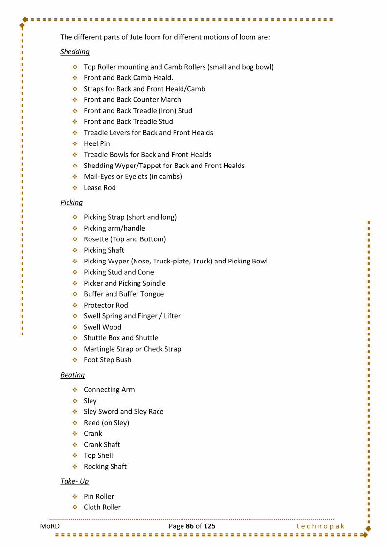
MoRD Page 86 of 125 t e c h n o p a k
The different parts of Jute loom for different motions of loom are:
Shedding
Top Roller mounting and Camb Rollers (small and bog bowl)
Front and Back Camb Heald.
Straps for Back and Front Heald/Camb
Front and Back Counter March
Front and Back Treadle (Iron) Stud
Front and Back Treadle Stud
Treadle Levers for Back and Front Healds
Heel Pin
Treadle Bowls for Back and Front Healds
Shedding Wyper/Tappet for Back and Front Healds
Mail-Eyes or Eyelets (in cambs)
Lease Rod
Picking
Picking Strap (short and long)
Picking arm/handle
Rosette (Top and Bottom)
Picking Shaft
Picking Wyper (Nose, Truck-plate, Truck) and Picking Bowl
Picking Stud and Cone
Picker and Picking Spindle
Buffer and Buffer Tongue
Protector Rod
Swell Spring and Finger / Lifter
Swell Wood
Shuttle Box and Shuttle
Martingle Strap or Check Strap
Foot Step Bush
Beating
Connecting Arm
Sley
Sley Sword and Sley Race
Reed (on Sley)
Crank
Crank Shaft
Top Shell
Rocking Shaft
Take- Up
Pin Roller
Cloth Roller

MoRD Page 87 of 125 t e c h n o p a k
Breast Beam (Front Rail)
Shotting Change Pinion and Compound Pinion
Pushing Pawl and Retaining or Releasing Pawl
Ratchet Wheel
Pin Roller Wheel and Carrier Wheel
Motion Lever and Motion Rod
Let-Off
Warp Beam or Weaver Beam
Drag Lever
Back Rail
Hand Wheel
Drag Chain
Drag Handle
Warp Protector Motion
Buffer and Buffer Tongue
Swell Wood
Swell Spring and Finger/Lifter
Protector Rod and Warp Protector Tongue
Auto Cop Loader Motion
Magazine and Magazine Bracket
Cop Plunget
Side Weft Fork and Gate
Latch and Catch
Swing Frame and Swing Frame Bracket
Coupling Rods
Bell Crank Lever
Actuating Lever and Cam
Push Rod
Hammer
Working of the Machine
The machine pulley of weaving machine gets its drive either from overhead line shaft or
from individual motor through loose pulley and fast pulley system. Machine pulley is fitted
by a key with the crank shaft of loom. Bottom shaft gets the drive through crank pinion
and bottom shaft pinion. The ratio of number of teeth of these two pinions is 1:2. Bottom
shaft is meant for transferring the motion to the shedding as well as picking system for a
hessian loom. Beating motion is operated through crank and connecting arm along with
sley and reed. Thus, two revolutions of the crank shaft results in two cycles of shedding,
picking and beating. Therefore, it is very much essential for a weaver to have knowledge
of all the motions of looms and their setting/tuning in particular. The principal motions of
a loom are to be synchronized for each rotation of the crank shaft. The synchronization of

MoRD Page 88 of 125 t e c h n o p a k
the motion is achieved through setting of different motions of loom as per “timing
diagram” or “Crank cycle” concept, which is a part of loom tuning activity.
12.5.2. Method Study
12.5.2.1. Weaver
9 Profession Name: Operation:
Product: Jute Bag Module: Weaving Machine: Date:
Received
Send
Handling before Operation Hand Used Freq
1. Carrying the Cops from the Cop Winding Department in a barrow. B/H 1/1
Sequence of Operations
1. Visually Watch the process very carefully to find the occurrence of any defect. R/H 1/1
2. Pick up the cop from the cop package barrow with right hand and loads (puts into the slot adjacent R/H 1/1
to shuttle) into the shuttle.
3. Forms the knot (incase of occurrence of any End Breakage)
R/H 1/1
L/H 1/1
B/H 1/1
B/H 1/1
Handling after Operation
1. Disposal of the cloth beam on carts for being taken to the Finishing Department. B/H 1/1
Operation Layout
METHOD DOCUMENT
Module No.: 9a. Weaver Weaving
Weaving Loom
Previous Operation: Beam ReceivingSequence of Output
Ascending
Following Operation: Damping Descending
(a) Take the yarn from the feeding side with left hand
(b) Take the yarn from the receiving side with right hand
(c) Form the knot
4. Doff the cloth beam at the receiving side of the machine by disengaging it with both hands.
Weaving Loom
Weaver

MoRD Page 89 of 125 t e c h n o p a k
12.5.2.2. Weaving Helper
12.5.3. Do’s and Don’ts
Do’s
Enquire from the out-going weaver (of previous shift) about the problem, if any,
for smooth running of looms and if anything is wrong, inform Sardar/Supervisor
In case of warp breakage, join or mend only by small weavers knots with proper
drawing and denting through reeds, cambs and lease rods.
Release warp beam tension gradually as the Beam empties
Use cops in full extent, as far as practicable. Use left over yarns in cop in case of
second quality as far as possible
Take care during shuttle change and starting of the looms, ensuring proper
placement of last pick or weft at fell of the cloth to avoid missing weft and bar
Check time to time warp sheets, whether there is any free or missing ends, big
knots, loose/taut ends and cross ends etc.
Use correct quality of cops according to cop mark displayed on your loom or
instructed
Keep the looms clean with special attention to the reeds, shotting change pinion, ,
cambs, treadle bowls/shedding wyper, picking stud/picking cones etc. clean looms
9 Profession Name: Operation:
Product: Jute Bag Module: Weaving Machine: Date:
Received
Send
Handling before Operation Hand Used Freq
1. Carrying the Cops from the Cop Winding Department in a barrow. B/H 1/1
Sequence of Operations
1. Find the yarn end in the warp beam. R/H 1/1
2. Take each yarn end and pass it over the back rest, passing it through the lease rod assembly R/H 1/1
(over the first lease rod and under the second or vice-versa) with both hands.
3. Pass each of the yarns through the mail-eye of the healds/cambs.
4. Pass the yarn ends through the dents of the Guide Reed and following machine parts with both B/H 1/1
hands (only if the process parameters are changes)
5. Knotting the yarns of the newly fed warp beam with the yarns of the previous fed sheet already B/H 1/1
running in the machine.
R/H 1/1
L/H 1/1
B/H 1/1
Operation Layout
METHOD DOCUMENT
Module No.: 9b. Weaving Helper Weaving
Weaving Loom
Previous Operation: Beam ReceivingSequence of Output
Ascending
Following Operation: Damping Descending
(a) Take the yarn from the newly fed warp beam with right hand
(b) Take the yarn already in motion
(c) Form the knot
Weaving Loom
Weaving Helper

MoRD Page 90 of 125 t e c h n o p a k
during beam change to make it free from jute fluffs and dirt/dust, for better
running of the looms and to avoid fire hazards
Put oil in picking spindle with a piece of fabric presoaked in oil whenever it is dry
Inform Sardar/Supervisor in case of faulty cloth and shuttle damage
Keep wastage in wastage bag only
Don’ts
Do not run looms unnecessarily at low or high speed
Don`t pick back
Do not waste warp yarns during beam tieing and doffing by cutting unnecessary
extra length of yarns
Do not use cops for tieing missing ends
Do not accumulate cop bundles near looms
Do not use single chain for beam tension, instead of using two chains at the two
ends of the warp beam
Do not mix up different quality in a single fabric
Do not use cops from the cop bundle without any quality mark.
Do not waste excess length of yarn during loading of cop in the shuttle
Do not cut repeatedly the excess tail ends of cops hanging from eco-loader
magazine. Do not cut tail ends at mouth of cops.
Do not use shotting change pinion for tightening picking arm.
12.6. Production, Efficiency and Quality
The work performance of a weaver mainly depends on three factors:
Improvement in production efficiency
Improvement in quality of products
Reduction in waste generation
Fabric Faults : Cause and Remedial Measures
12.6.1. Improvement in production efficiency
Factors Control Measures
1. Warp Breaks
Warp Yarn Tension Warp yarn Quality Warp Yarn preparation Setting of the loom (for Shedding, Beating, Picking and take-up motions) Elimination of Big Knots
2. Weft Breaks
Condition of the Shuttle Quality and build of Cop Weft Yarn Quality Setting of Loom
3. Loom Stoppages
Improper Loom Tuning Warp Yarn Mending Beam Change and Shuttle Change Time

MoRD Page 91 of 125 t e c h n o p a k
12.6.2. Improvement in quality
Improvement in Quality also automatically improves the productivity. Factors which
influence the improvement in quality are:
Total quality consciousness and adherence to the specification and manufacturing
instructions.
Knowledge of fabric faults/defects and their remedial measures.
Perfect arrangement of the warp yarn eliminating crossed ends, taut ends, missing
ends and big knots etc.
Proper arrangement of the warp yarn on the lease rod, camb and reed
Proper maintenance of the warp tension and fabric tension
Maintenance of proper shed depth, tension of the warp yarns at the selvedges.
Controlling the take up motion and use of proper shotting change pinion
Checking the number of warp yarns and controlling the cloth width.
Use of correct warp count, weft count, correct reed porter and proper camb
fileying.
Use of small weavers knot in case of broken ends and ensuring its passage through
lease rod, camb and reed. Big and loose knots should not be allowed.
Avoid quality-mix up. Use of proper tags
Avoidance of reed marks and bars etc.
12.6.3. Reduction of wastage
Yarn waste is hard waste and is costly even if recycled. Saving of waste has therefore
direct influence in productivity and profit:
Knowledge of quality deterioration of yarn
Knowledge about reasons and area for generation of yarn wastage
Elimination of drawing of excess yarn before tieing-up. Running off warp yarn (in
beam) till exhaustion.
Elimination of malpractices like using the cop for joining or mending missing warp
ends
Use of cop to the full extent i.e. use of left over yarns in cops.
Proper handling of spools, cops and beams
Use of defective cop to the possible extent
Avoiding pick back
Use and maintenance of individual wastage bag and keeping it at proper place.
Use of correct warp and weft count.
Avoid unnecessary accumulation of cops.

MoRD Page 92 of 125 t e c h n o p a k
12.6.4. Fabric Faults: Cause and Remedial Measures
Defects Definition Cause Remedial Measures
Weft Bars Difference of appearance in a portion of a cloth from the normal weft spacing due to presence of more no. of picks/inch causing densed weft spacing
Mechanical Faults in the take-up motion, and eccentricity of take-up roller etc.
Removal of eccentricity of take-up roller or mechanical faults in take-up motion
Bias Portion of the fabrics where warp and weft are not at right angles to each other
Unequal tension on the warp threads across width of the fabric during weaving
Adjust warp yarn tension to keep equal tension of warp yarn across the width of the fabric.
Broken/Missing Ends
A narrow warp wise void in the fabrics caused by missing warp
Excess warp yarn tensions , excessive frictions by rough or worn out dents, too tight camb tieing
Adjust warp yarn tension, replace worn out or damaged reed or repair bent reed
Gaw Bunch of missing pick from a portion or in full width of the fabric
Cut shuttle eye, damaged shuttle tension rings or pins, improper piecing during cop making
Proper reason to be identified and rectified
Defective Selvedges
Non-Uniform (not straight) or irregular selvedges due to slack or tight selvedges
Improper tension of the selvedge yarn (low or high), tight picks, differential shrinkage between selvedge and body of the cloth, excessive weft yarn tensions, slack picking strap, hard and soft pick, damaged inside surface of shuttle
Tension of selvedge threads and weft yarn are to be properly adjusted and maintained
Shuttle smash Ruptured cloth characterized by many broken ends and picks, caused by entrapment of shuttle in the shed.
Shuttle entrapment due to weak picking force, defective picking motion, malfunctioning of warp protector motion, inadequate shed depth, worn out picker and picking spindle
Do proper loom tuning to adjust picking force
Snarl Short Length of weft yarn either entangled or twisted on itself and entrapped in fabric during interlacement of weft yarns with warp yarns
Soft Cop, less than standard cop diameter, worn out inside shuttle ring, bad or damaged shuttle and cover damaged bristles in shuttles
Use cop of proper diameter, proper twist of weft yarn, Use shuttle of good quality

MoRD Page 93 of 125 t e c h n o p a k
Defects Definition Cause Remedial Measures
Warp/Weft Float
A part in fabric where warp/weft is not interlaced properly
Entanglement of broken warp ends, large knot in warp yarns, causing interference in up and down movement of warp yarns
To keep watch on broken warp thread and their proper harnessing, to rectify the defects
Scob A portion in fabric where warp and weft yarn fully escapes interlacement
Due to breakage of warp yarn between and heald the broken warp ends when entangled with surrounding warp yarns and/or mail-eyes of heald preventing required up and down movement of corresponding warp yarns forming insufficient depth of shed, for which it escapes the interlacement
Keep watch on broken warp yarns so that they do not entangle with surrounding warp ends or male-eyes. If it happens already, weft yarns in that portion of width are to be removed and fresh weaving is done
Reed Mark Running of few warp ends in pairs along the length of the fabric
Damaged or defective reed, incorrect adjustment of backrest and lease rods or the shedding
Damaged or defective reed should be replaced. Adjust backrest, lease rods, Late shedding should be avoided.
Weft Bar Bias Broken Ends
Gaw Defective Selvedges Shuttle Smash

MoRD Page 94 of 125 t e c h n o p a k
12.7. Types of Mazdoor
S. No. Mazdoor Type Job Description
1 Weaving Mazdoor Carries the empty shuttles from Shuttle issue Department to Weaving Department
2 Beam Carrier Carries the weaver`s Beam from Weaving Department to Finishing Department
Snarl Weft Float Scob
Reed Mark
Fig 12.c Fabric Faults
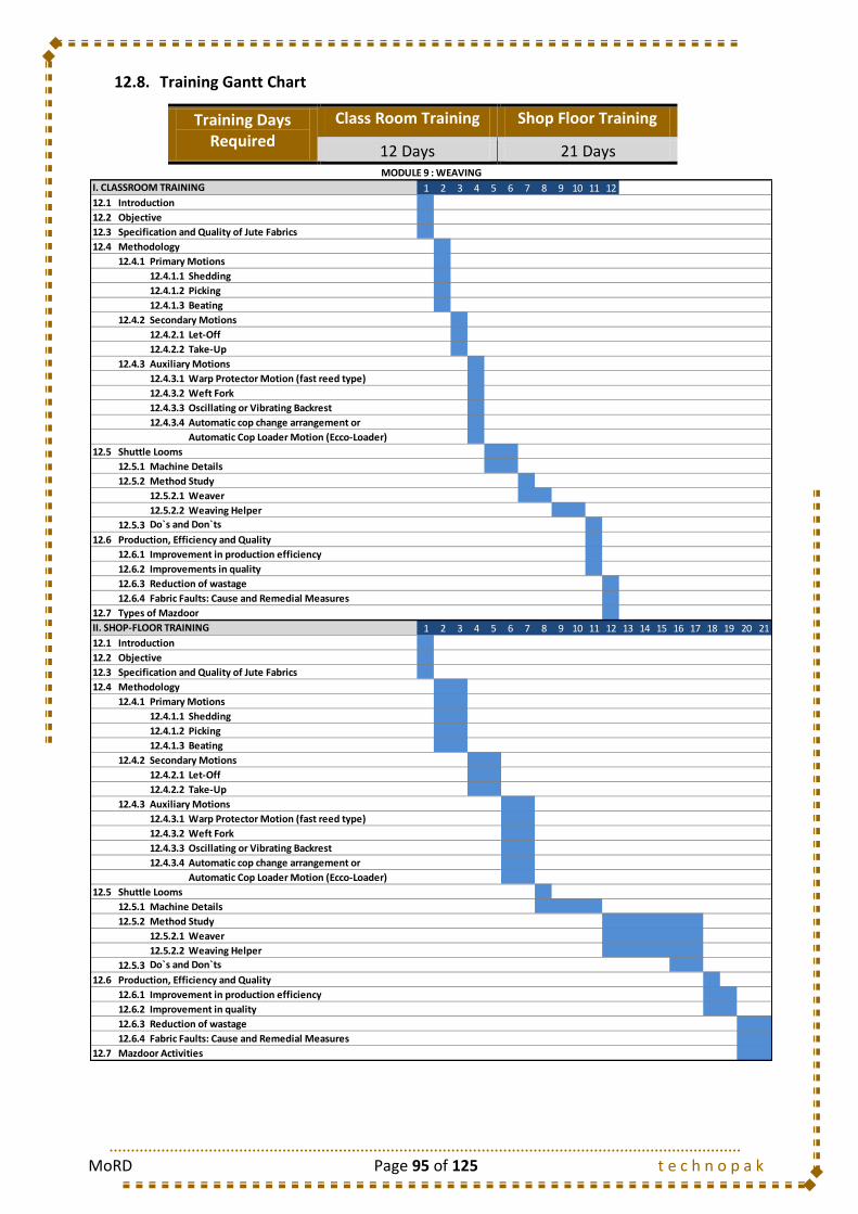
MoRD Page 95 of 125 t e c h n o p a k
12.8. Training Gantt Chart
Training Days Required
Class Room Training Shop Floor Training
12 Days 21 Days
1 2 3 4 5 6 7 8 9 10 11 12
12.1 Introduction
12.2 Objective
12.3 Specification and Quality of Jute Fabrics
12.4 Methodology
12.4.1 Primary Motions
12.4.1.1 Shedding
12.4.1.2 Picking
12.4.1.3 Beating
12.4.2 Secondary Motions
12.4.2.1 Let-Off
12.4.2.2 Take-Up
12.4.3 Auxiliary Motions
12.4.3.1 Warp Protector Motion (fast reed type)
12.4.3.2 Weft Fork
12.4.3.3 Oscillating or Vibrating Backrest
12.4.3.4 Automatic cop change arrangement or
Automatic Cop Loader Motion (Ecco-Loader)
12.5 Shuttle Looms
12.5.1 Machine Details
12.5.2 Method Study
12.5.2.1 Weaver
12.5.2.2 Weaving Helper
12.5.3
12.6 Production, Efficiency and Quality
12.6.1 Improvement in production efficiency
12.6.2 Improvements in quality
12.6.3 Reduction of wastage
12.6.4 Fabric Faults: Cause and Remedial Measures
12.7 Types of Mazdoor
1 2 3 4 5 6 7 8 9 10 11 12 13 14 15 16 17 18 19 20 21
12.1 Introduction
12.2 Objective
12.3 Specification and Quality of Jute Fabrics
12.4 Methodology
12.4.1 Primary Motions
12.4.1.1 Shedding
12.4.1.2 Picking
12.4.1.3 Beating
12.4.2 Secondary Motions
12.4.2.1 Let-Off
12.4.2.2 Take-Up
12.4.3 Auxiliary Motions
12.4.3.1 Warp Protector Motion (fast reed type)
12.4.3.2 Weft Fork
12.4.3.3 Oscillating or Vibrating Backrest
12.4.3.4 Automatic cop change arrangement or
Automatic Cop Loader Motion (Ecco-Loader)
12.5 Shuttle Looms
12.5.1 Machine Details
12.5.2 Method Study
12.5.2.1 Weaver
12.5.2.2 Weaving Helper
12.5.3
12.6 Production, Efficiency and Quality
12.6.1 Improvement in production efficiency
12.6.2 Improvement in quality
12.6.3 Reduction of wastage
12.6.4 Fabric Faults: Cause and Remedial Measures
12.7
Do`s and Don`ts
Mazdoor Activities
II. SHOP-FLOOR TRAINING
Do`s and Don`ts
MODULE 9 : WEAVING
I. CLASSROOM TRAINING

MoRD Page 96 of 125 t e c h n o p a k
13. MODULE 10: FINISHING OF JUTE CLOTH
13.1. Introduction
Jute fabric after weaving needs to go through some additional processes to get the fabric
shaped and to make the fabric ready for the end use and sales. All the process that the
Jute fabric undergoes after the process of weaving is collectively termed as “Finishing”. As
Jute bags of Hessian and Sacking type are mostly cheaper and are of coarser variety, they
do not undergo any chemical finishing. Although there are some specific end uses where
Jute fabric undergoes chemical process of dyeing and finishing but mostly jute fabric end
uses are colourless bags which eliminates the process of chemical finishing.
Three important factors determine the mechanical finishing process to be followed in the
jute industry. They are:
The specification and desired quality of the products
The market price and manufacturing cost of the product
The type of fabrics or bags and their end-use requirements
Generally the jute fabrics after the process of weaving are stiff, harsh and hairy. Also, the
other parameters like extensibility, drape, abrasion resistance, crease resistance are poor.
Hence proper finishing processes are essential to remove the weaving faults and to impart
suitable handle to the end product.
Jute Cloth Production
(Fine Side)
Damping
Calendaring and Inspection
Cloth Repairing
Lapping and Measurement
Arranging
Baling
Storing
Dispatching
Jute Cloth Production
(Coarse Side)
Damping
Calendaring and Inspection
Cloth Repairing
Lapping
Arranging
Packing
Storing
Dispatching
Jute Bag Production
(Fine and Coarser Side)
Damping
Calendaring and Inspection
Repairing
Cutting
Sewing
Bundling
Packing
Storing
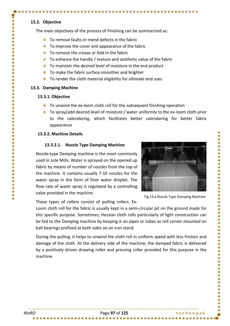
MoRD Page 97 of 125 t e c h n o p a k
13.2. Objective
The main objectives of the process of Finishing can be summarized as:
To remove faults or mend defects in the fabric
To improve the cover and appearance of the fabric
To remove the crease or fold in the fabric
To enhance the handle / texture and aesthetic value of the fabric
To maintain the desired level of moisture in the end product
To make the fabric surface smoother and brighter
To render the cloth material eligibility for ultimate end uses
13.3. Damping Machine
13.3.1. Objective
To unwind the ex-loom cloth roll for the subsequent finishing operation
To spray/add desired level of moisture / water uniformly to the ex-loom cloth prior
to the calendaring, which facilitates better calendaring for better fabric
appearance
13.3.2. Machine Details
13.3.2.1. Nozzle Type Damping Machine
Nozzle-type Damping machine is the most commonly
used in Jute Mills. Water is sprayed on the opened up
fabric by means of number of nozzles from the top of
the machine. It contains usually 7-10 nozzles for the
water spray in the form of finer water droplet. The
flow rate of water spray is regulated by a controlling
valve provided in the machine.
These types of rollers consist of pulling rollers. Ex-
Loom cloth roll for the fabric is usually kept in a semi-circular pit on the ground made for
this specific purpose. Sometimes, Hessian cloth rolls particularly of light construction can
be fed to the Damping machine by keeping it on pipes or tubes as roll center mounted on
ball bearings prefixed at both sides on an iron stand.
During the pulling, it helps to unwind the cloth roll in uniform speed with less friction and
damage of the cloth. At the delivery side of the machine, the damped fabric is delivered
by a positively driven drawing roller and pressing roller provided for this purpose in the
machine.
Fig 13.a Nozzle Type Damping Machine

MoRD Page 98 of 125 t e c h n o p a k
13.3.3. Method Study
13.3.3.1. Feeder- Damping
13.3.3.2. Receiver- Damping
10 Profession Name: Operation:
Product: Jute Bag Module: Finishing Machine: Date:
Received
Send
Handling before Operation Hand Used Freq
1. Carrying the woven cloth Roll from the Weaving Department to the Finishing Department. B/H 1/1
Sequence of Operations
1. Take the jute cloth with both hands. B/H 1/1
2. Throw the fabric across the machine from the feeding side to the receiving side aiming B/H 1/1
the nip of the rotating rollers.
3. Adjust the fabric finally. B/H 1/1
Operation Layout
Descending
METHOD DOCUMENT
Module No.: 10a. Feeder- Damping Damping
Damping Machine
Previous Operation: WeavingSequence of Output
Ascending
Following Operation: Damping Receiving
Damping Machine
Damping Feeder
10 Profession Name: Operation:
Product: Jute Bag Module: Finishing Machine: Date:
Received
Send
Hand Used Freq
Sequence of Operations
1. Takes (Receives) the jute cloth with both hands. B/H 1/1
2. Watch the fabric very carefully to check the occurrence of any defect. B/H 1/1
Handling after Operation
1. Disposal of the Jute Cloth to the Calendaring Section in a barrow. B/H 1/1
Operation Layout
Descending
METHOD DOCUMENT
Module No.: 10b. Receiver- Damping Damping
Damping Machine
Previous Operation: Damping FeedingSequence of Output
Ascending
Following Operation: Calendaring
Damping Machine
Receiver
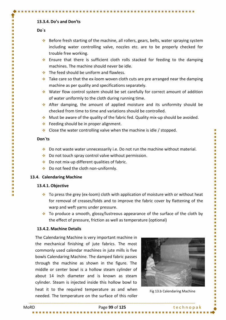
MoRD Page 99 of 125 t e c h n o p a k
13.3.4. Do’s and Don’ts
Do`s
Before fresh starting of the machine, all rollers, gears, belts, water spraying system
including water controlling valve, nozzles etc. are to be properly checked for
trouble free working.
Ensure that there is sufficient cloth rolls stacked for feeding to the damping
machines. The machine should never be idle.
The feed should be uniform and flawless.
Take care so that the ex-loom woven cloth cuts are pre arranged near the damping
machine as per quality and specifications separately.
Water flow control system should be set carefully for correct amount of addition
of water uniformly to the cloth during running time.
After damping, the amount of applied moisture and its uniformity should be
checked from time to time and variations should be controlled.
Must be aware of the quality of the fabric fed. Quality mix-up should be avoided.
Feeding should be in proper alignment.
Close the water controlling valve when the machine is idle / stopped.
Don`ts
Do not waste water unnecessarily i.e. Do not run the machine without material.
Do not touch spray control valve without permission.
Do not mix-up different qualities of fabric.
Do not feed the cloth non-uniformly.
13.4. Calendaring Machine
13.4.1. Objective
To press the grey (ex-loom) cloth with application of moisture with or without heat
for removal of creases/folds and to improve the fabric cover by flattening of the
warp and weft yarns under pressure.
To produce a smooth, glossy/lustreous appearance of the surface of the cloth by
the effect of pressure, friction as well as temperature (optional)
13.4.2. Machine Details
The Calendaring Machine is very important machine in
the mechanical finishing of jute fabrics. The most
commonly used calendar machines in jute mills is five
bowls Calendaring Machine. The damped fabric passes
through the machine as shown in the figure. The
middle or center bowl is a hollow steam cylinder of
about 14 inch diameter and is known as steam
cylinder. Steam is injected inside this hollow bowl to
heat it to the required temperature as and when
needed. The temperature on the surface of this roller Fig 13.b Calendaring Machine

MoRD Page 100 of 125 t e c h n o p a k
is controlled by controlling the amount of steam flow and steam pressure. The two bowls
just at the top or below of this bowls are the paper bowls and the next top and bottom
bowls are iron bowls. At the feed end, there are five tension rails which are mainly
present for adjusting the tension of the feed fabric.
Different types of calendar finish can be obtained by adjusting the feed tension of the
cloth through various rails at the feed. Controlling the overfeed or underfeed of the cloth
subjected to the different tension by rails and different pressure by different wraps and
nips combined with or without heat by steam cylinder in the calendaring machine, the
length of the fabric can be increased at the compensation of widthwise shrinkage of the
fabric. If the tension along the width of the two selvedge ends of the fabric is not equal
and uniform, there may be a “Bias” developed in the fabric
In industry, the normal steam pressure in the calendaring machine is kept around 25
lbs/sq, inch for hessian and 30 lbs/sq. inch for sacking fabrics.
13.4.3. Method Study
13.4.3.1. Feeder- Calendaring
10 Profession Name: Operation:
Product: Jute Bag Module: Finishing Machine: Date:
Received
Send
Handling before Operation Hand Used Freq
1. Carrying the damped jute cloth from damping section to the calendaring section. B/H 1/1
Sequence of Operations
1. Takes the jute cloth with both hands. B/H 1/1
2. Passes the fabric through nip of the first pair of bottom bowls (paper bowl and iron bowl) and B/H 1/1
again bring back the fabric to the feeding side through the nip of the 2nd pair of bowls (paper
bowl and center bowl)
3. Passes the fabric through nip of the 3rd pair of bowls from bottom (steam bowl and paper bowl) B/H 1/1
and again bring back the fabric to the feeding side through the nip of the 4th pair of bowls
(paper bowl and iron bowl)
4. Take the cloth above the iron bowl and pass it to the receiving side of the Calendaring Machine. B/H 1/1
Operation Layout
Descending
METHOD DOCUMENT
Module No.:10c. Feeder-
CalendaringCalendaring
Calendaring Machine
Previous Operation: Damping ReceivingSequence of Output
Ascending
Following Operation: Calendaring Receiving
Calendaring Machine
Feeder
MoRD Page 101 of 125 t e c h n o p a k
13.4.3.2. Receiver- Calendaring
13.4.4. Do’s and Don’ts
Do`s
Semi-folded jute fabrics after proper damping should be properly placed before
feed end of the machine ensuring perfect square –on feed and it must be properly
repaired / mended whenever required. End to end joining by sewing between cuts
must be ensured in advance.
Steam pressure should be properly adjusted by the stop valve as per requirement.
Pressure of different bowls/cylinders and additional dead weight should be
adjusted according to the type of fabric and type of calendar finish required.
At the feed end, number of rails to be engaged should be carefully fixed as per the
extent of tension required and this should be maintained properly.
Proper square-on and uniform feeding of the fabric must be ensured avoiding
calendaring faults
Initially follow the slow running for gradual starting of the machine when the cloth
is being entered in the machine. The passage of fabric through correct number of
nips is ensured.
Satisfactory reversal at any desired interval must be ensured and quick reversal in
case of emergency should be confirmed.
Length and width of the calendared fabrics must be thoroughly checked.
No creases of the cloth are should be allowed before and after calendaring.
Calendared fabric cuts are to be kept separately as per quality of the fabric.
10 Profession Name: Operation:
Product: Jute Bag Module: Finishing Machine: Date:
Received
Send
Hand Used Freq
Sequence of Operations
1. Takes (Receives) the jute cloth with both hands. B/H 1/1
2. Watch the fabric very carefully to check the occurrence of any defect.
3. Rectify the defects with both hands B/H 1/1
Handling after Operation
1. Disposal of the Jute Cloth to the Lapping Section in a barrow. B/H 1/1
Operation Layout
Descending
METHOD DOCUMENT
Module No.:10d. Receiver-
CalendaringCalendaring
Calendaring Machine
Previous Operation: Calendaring FeedingSequence of Output
Ascending
Following Operation: Lapping Feeding
Calendaring Machine
Receiver

MoRD Page 102 of 125 t e c h n o p a k
Mending should be done when required.
When two or three fabrics are run side by side simultaneously on a calendar
machine, the feeder has to ensure that the widthwise position of the fabrics over
the bowl is changed from time to time, by changing the position of the collar,
which are to be shifted on the rail so that fabrics do not pass over the same place
for a long period.
While starting the machine after a long stop, the feeder should not allow bowl
pressure to act until steam cylinder is heated.
No foreign matters are to be allowed to enter the fabric.
Don`ts
Do not allow any fabric gaw/net/other major defects to be fed in calendar machine
without its repair.
Do not allow different bowls to be in contact with each other when the machine is
stopped. There should be at least ¼ inch gap between steam cylinder and top
paper bowl.
Do not run the machine without material.
Do not allow any drip of water or oil on any of the calendar bowls. It would create
stain on the cloth.
Do not allow iron bowls or paper bowl to get wetted or damped by anyway.
Do not run the machine before the steam cylinder reaches desired temperature.
Do not change rail tension or number of nips etc. without getting confirmed.
Do not allow any defective fabric to enter the calendaring machine.
13.5. Lapping Machine
13.5.1. Objective
To fold the cloth continuously upon itself in a pre-selected/required lap length and
width for ease of handling, transportation and packing.
To fold the cloth in a market acceptable form and to make ultimately dispatchable/
transportable pack of bale of specified dimension, as per customers or market
requirement.
13.5.2. Machine Details
The important parts of a lapping machine are as
follows:
An oscillating knife and bracket on the
delivery table of the machine to facilitate
lapping of the cloth aided with grip or bars
present to secure/hold the lapped cloth to
allow next folding.
Tensioning bars with sliding collars to adjust
tension of the feed cloth
A convex wooden table at the receiving end where the cloth is received.
Fig 13.c Lapping Machine

MoRD Page 103 of 125 t e c h n o p a k
An inclined table at the receiving end where the folded or lapped cloth is pulled
from the convex wooden table
Another optional feature of this machine is manual cutting arrangement of cloth
into the bag length on the lapping table.
In the lapping machine, the lap length for folding or for cutting is to be adjusted in the
machine very accurately. Lapping machines of different width are available. Normally
smaller width lapping machine have 60 inch width and longer width have 90 inch width.
Cloths shall be folded in full width with an average fold/lap length of 80 inch.
For 60 inch width lapping machine, the frequency of lapping or folding by oscillating knife
is 36-37 stroke/min. and the same for the 90 inch width lapping machine is 30-32
strokes.min.
13.5.3. Method Study
13.5.3.1. Feeder- Lapping
10 Profession Name: Operation:
Product: Jute Bag Module: Finishing Machine: Date:
Received
Send
Handling before Operation Hand Used Freq
1. Carrying the woven cloth Roll from the Calendaring section to the Lapping section. B/H 1/1
Sequence of Operations
1. Take the jute cloth with both hands. B/H 1/1
2. Throw the fabric across the machine from the feeding side to the receiving side aiming the B/H 1/1
oscillating bracket that facilitates the lapping.
3. Adjust the fabric finally. B/H 1/1
Operation Layout
Descending
METHOD DOCUMENT
Module No.: 10e. Feeder- Lapping Lapping
Lapping Machine
Previous Operation: Calendaring ReceivingSequence of Output
Ascending
Following Operation: Lapping Receiving
Lapping Machine
Lapping Feeder

MoRD Page 104 of 125 t e c h n o p a k
13.5.3.2. Receiver- Lapping
13.5.4. Do’s and Don’ts
Do`s
Proper feeding of the fabric should be ensured by the operator. Operator has to
ensure proper tensioning and placing of collars on tension bars at proper place,
during feeding of the fabric.
Operator should avoid any defective fabric to be fed for lapping.
Short and medium cuts of the fabric should be identified and to be kept separately
for lapping/folding those separately or as per instruction from Sardar.
Lapped fabric must be kept separately with respect to quality with quality marks.
Operator must paste the chit for total measured length or put measuring stamp
inside each cut of lapped fabric.
Lap length should be properly adjusted. It must be checked from time to time after
lapping by S.Q.C personnel.
Don`ts
Do not allow high tension or slackness in the fabric during lapping (with or without
cutting as required)
Do not run the machine empty
Do not allow quality mix-up.
Do not allow defective cloth to be fed.
10 Profession Name: Operation:
Product: Jute Bag Module: Finishing Machine: Date:
Received
Send
Hand Used Freq
Sequence of Operations
1. Takes (Receives) the jute cloth with both hands. B/H 1/1
2. Watch the fabric very carefully to check the occurrence of any defect.
3. Rectify the defects with both hands B/H 1/1
4. Control and Ensurence so that the lapping takes place correctly. B/H 1/1
Handling after Operation
1. Disposal of the Jute Cloth to the Cutting Section in a barrow. B/H 1/1
Operation Layout
Descending
METHOD DOCUMENT
Module No.: 10f. Receiver- Lapping Lapping
Lapping Machine
Previous Operation: Lapping FeedingSequence of Output
Ascending
Following Operation: Cutting
Lapping Machine
Receiver
MoRD Page 105 of 125 t e c h n o p a k
13.6. Cutting Machine
13.6.1. Objective
To cut the calendared jute cloth into pieces in required sizes to manufacture jute
bags or sheets
13.6.2. Machine Details
To cut a pre-fixed length of a jute cloth, the following types of cutting machines are used:
Rotary Cutting Machine: Jute cloth is continuously cut into a pre-fixed length by
means of a rotary blade.
Gillotin Cutting Machine: In this cutting machine, the blade moves forward and
backward parallel to the floor with the help of a cam and a connecting arm to cut a
definite length of the fabric, as per adjustment made for any specific length of
cutting required.
Scimitar Cut and Folding Machine: This type of cutting machine cuts the jute fabric
in a definite length and folds it after cutting. This is not commonly used in jute
mills because of maintenance difficulty for its complex mechanism.
Lap and Cutting Machine: Generally for light quality fabrics and more than 120
inch cut length, these type of cutting machines are used. Here the fabric is lap
folded by lapping machine and then cut by hand knife. This type is not popular in
Jute Mills.
Each Cutting machine has a cutting constant value. The cutting size of a Jute cloth shall be
controlled with a change pinion called “Cutting Change Pinion”. This cutting shall take
place with the to and fro or rotary movement of the cutting blade. The blade gets
movement from a properly designed cal through connecting arms. The use of cutting
change pinion fitted/required for a particular quality fabric is to commensurate with
cutting constant value of the cutting machine, shall be displayed on a board of the cutting
machine.

MoRD Page 106 of 125 t e c h n o p a k
13.6.3. Method Study
13.6.3.1. Cutting Machine Operator
13.6.4. Do’s and Don’ts
Do`s
Before machine starting, the start and stop switch, cut blade setting, blade
condition and drive of the blade must be checked.
Check the cam, connecting arm and gear meshing. There should not be any
damage or worn out condition in the cam; the connecting arm should not be loose
and gear should be meshed properly.
The fabric is to be fed straight and there should not be any bias feeding at all to
avoid bias cutting.
Segregation of defective cuts/Pieces must be ensured. In case of defective cutting,
cutting blade sharpness is to be checked.
Length of the cutting is to be ensured.
Mixing of cut pieces for different quality jute bags are to be avoided.
Don`ts
Do not allow any short length of cutting.
10 Profession Name: Operation:
Product: Jute Bag Module: Finishing Machine: Date:
Received
Send
Handling before Operation Hand Used Freq
1. Carrying the woven cloth Roll from the Calendaring section to the Lapping section. B/H 1/1
Sequence of Operations
1. Take the jute cloth with both hands. B/H 1/1
2. Throw the fabric across the machine from the feeding side to the receiving side aiming the B/H 1/1
Feed Roller.
3. Adjust the fabric finally. B/H 1/1
B/H 1/1
6. Segregate/Rectify any defect on the cloth B/H 1/1
Handling after Operation
1. Disposal of the cloth to the Sewing Department in the barrow. B/H 1/1
Operation Layout
METHOD DOCUMENT
Module No.: 10g. Cutting Operator Cutting
Cutting Machine
Operator
Previous Operation: Lapping ReceivingSequence of Output
Ascending
Following Operation: Sack-Sewing Descending
4. Takes (Receives) the jute cloth with both hands.
5. Watch the fabric very carefully to check the occurrence of any defect.
Cutting Machine
Cutting Machine Operator

MoRD Page 107 of 125 t e c h n o p a k
Do not allow any bias cutting and hence don`t feed the fabric bias.
Do not allow the high tension or sagging of the fabric during feed for cutting the
cloth.
Do not mix-up the quality of the cut-pieces with other quality.
Do not feed defective cloth.
13.7. Types of Mazdoor
S. No. Mazdoor Type Job Description
1 Cloth Carrier Carries the Jute cloth/rolls from one process to another in Finishing department

MoRD Page 108 of 125 t e c h n o p a k
13.8. Training Gantt Chart
Training Days Required
Class Room Training Shop Floor Training
9 Days 9 Days
1 2 3 4 5 6 7 8 9
13.1 Introduction
13.2 Objective
13.3 Damping Machine
13.3.1 Objective
13.3.2 Machine Details
13.3.2.1 Nozzle Type Damping Machine
13.3.3 Method Study
13.3.3.1 Feeder- Damping
13.3.3.2 Receiver- Damping
13.3.4 Do's and Don'ts
13.4 Calendaring Machine
13.4.1 Objective
13.4.2 Machine Details
13.4.3 Method Study
13.4.3.1 Feeder- Calendaring
13.4.3.2 Receiver- Calendaring
13.4.4 Do's and Don'ts
13.5 Lapping Machine
13.5.1 Objective
13.5.2 Machine Details
13.5.3 Method Study
13.5.3.1 Feeder- Lapping
13.5.3.2 Receiver- Lapping
13.5.4 Do's and Don'ts
13.6 Cutting Machine
13.6.1 Objective
13.6.2 Machine Details
13.6.3 Method Study
13.6.3.1 Cutting Machine Operator
13.6.4 Do's and Don'ts
13.7 Types of Mazdoor
1 2 3 4 5 6 7 8 9
13.1 Introduction
13.2 Objective
13.3 Damping Machine
13.3.1 Objective
13.3.2 Machine Details
13.3.2.1 Nozzle Type Damping Machine
13.3.3 Method Study
13.3.3.1 Feeder- Damping
13.3.3.2 Receiver- Damping
13.3.4 Do's and Don'ts
13.4 Calendaring Machine
13.4.1 Objective
13.4.2 Machine Details
13.4.3 Method Study
13.4.3.1 Feeder- Calendaring
13.4.3.2 Receiver- Calendaring
13.4.4 Do's and Don'ts
13.5 Lapping Machine
13.5.1 Objective
13.5.2 Machine Details
13.5.3 Method Study
13.5.3.1 Feeder- Lapping
13.5.3.2 Receiver- Lapping
13.5.4 Do's and Don'ts
13.6 Cutting Machine
13.6.1 Objective
13.6.2 Machine Details
13.6.3 Method Study
13.6.3.1 Cutting Machine Operator
13.6.4 Do's and Don'ts
13.7
MODULE 10 : FINISHING
I. CLASSROOM TRAINING
II. SHOP-FLOOR TRAINING
Mazdoor Activities
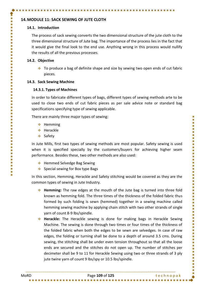
MoRD Page 109 of 125 t e c h n o p a k
14. MODULE 11: SACK SEWING OF JUTE CLOTH
14.1. Introduction
The process of sack sewing converts the two dimensional structure of the jute cloth to the
three dimensional structure of Jute bag. The importance of the process lies in the fact that
it would give the final look to the end use. Anything wrong in this process would nullify
the results of all the previous processes.
14.2. Objective
To produce a bag of definite shape and size by sewing two open ends of cut fabric
pieces.
14.3. Sack Sewing Machine
14.3.1. Types of Machines
In order to fabricate different types of bags, different types of sewing methods arte to be
used to close two ends of cut fabric pieces as per sale advice note or standard bag
specifications specifying type of sewing applicable.
There are mainly three major types of sewing:
Hemming
Herackle
Safety
In Jute Mills, first two types of sewing methods are most popular. Safety sewing is used
when it is specified specially by the customers/buyers for achieving higher seam
performance. Besides these, two other methods are also used:
Hemmed Selvedge Bag Sewing
Special sewing for Box type Bags
In this section, Hemming, Herackle and Safety stitching would be covered as they are the
common types of sewing in Jute Industry.
Hemming: The raw edges at the mouth of the Jute bag is turned into three fold
known as hemming fold. The three times of the thickness of the folded fabric thus
formed by such folding is sewn (hemmed) together in a sewing machine called
hemming sewing machine by applying chain stitch with two other strands of single
yarn of count 8-9 lbs/spindle.
Herackle: The Herackle sewing is done for making bags in Herackle Sewing
Machine. The sewing is done through two times or four times of the thickness of
the folded fabric when both the edges to be sewn are selvedges. In case of raw
edges, the folding or turning shall be done to a depth of around 3.5 cms. During
sewing, the stitching shall be under even tension throughout so that all the loose
ends are secured and the stitches do not open up. The number of stitches per
decimeter shall be 9 to 11 for Herackle Sewing using two or three strands of 3 ply
jute twine yarn of count 9 lbs/spy or 10.5 lbs/spindle.

MoRD Page 110 of 125 t e c h n o p a k
Safety Stitching: An extra line of chain stitch (at the inner edge of a herackle type
sewing) may be provided Hemming Sewing Machine which is termed as Sfety
Sewing. In safety stitch, normally two strands of two ply jute twine of count 9
lbs/spindle is used. The number of stitches per decimeter is also 9-11. For A-twill
bag, this type of safety sewing is used. Sometimes, lock-stitch may also be used for
safety stitch. Safety stitch is used for achieving higher seam performance as safety,
when the main stitch even fails.
14.3.2. Types of Stitch
Four types of stitches are commonly used in jute bags. These are given below with a brief
description:
Chain Stitch: This is a double loop
continuous stitch as shown in the
figure, using a looper thread and a
separate needle thread. Cotton
twines were used earlier for such
double looped stitch. Now-a-days, chain stitches are given in by sewing machine
with jute twines. This stitching is used for Hemming type sewing of Jute bags, to
sew the raw edges of the mouth of the jute bag. For the stitch, sewing thread is
supplied from two spools / cone and one eyed needle is used. In this sewing, a
chain is formed in one side of the bag, which is elastic in nature. It has a stitch
density of 9 to 11 stitches/decimeter.
Lock Stitch: In Lock Stitch, there is
inter-crossing between the needle
thread and locking thread and thus it
is very strong in nature, but not so
elastic unlike chain stitch. Here, two
types of stitching threads are
supplied from two bobbins, one is bigger and the other is smaller. In case of
Tarpaulin and Twill bags, it has a stitch density of 9-11 stitches/decimeter.
Sometimes, lock stitch is also used as safety stitch.
Overhead Stitch: In jute mills, this
type of stitch was generally used
earlier for heavy jute bags. But
overhead stitching machine has low
productivity i.e. only 500 stitches per
minute and hence day by day mills are discarding this type of sewing machine. The
needle of the machine is like a spiral hook. After this type sewing the edge is also
folded round to make with the stitch round hook.
Herackle Stitch: The machine used for
Herackle Stitch is known as Herackle
Sewing Machine. It is more complex
than overhead sewing machine. Here,

MoRD Page 111 of 125 t e c h n o p a k
the sewing depends on looping mechanism. In this machine, two sewing twine
thread are supplied from two bobbins / spools / cone. The production rate of this
machine is very high and is about 1500 stitches per minute. Jute twines are used as
sewing thread and stitch density is usually 9-11 stitches per decimeter.
14.3.3. Types of Seam
Types of seams with different nature of folds/joints required for a particular type of jute
bag depends upon the type of bag and its uses. Different types of folds/joints during
preparation of different seams are discussed below:
Plain Seam: Two edges of the fabric is
taken together and sewn simply through
two layers of the fabric and then the bag
is turned inside out so that the sewing
becomes invisible. This type of seam joining is called Plain Seam.
‘M’ Seam: During sewing of the bag, the
two edges of the fabric is folded inside at
a definite length (about 1.5 inch in each
side) in a M-fashion. In this case, the
stitch is done through four layers of
folded fabric. Here sides of the bag is kept
as it is and no turn over is required. This type of seam joining is called M seam.
Counter Laid Seam: In this case, both the
edges of the fabric is first folded to
corresponding outside and then single or
double stitched simply over four layers of
the fabric. Then the bag is turned inside
out to make the stitch invisible. This type
of seam joining is called counter laid seam.
Fold-Over Seam: The two edges of the
fabric outside in the same direction and
upward at a time and then stitched over
four layers of folded fabrics. This type is
known as Fold-Over Seam.
Over Edge Seam on Selvedges (with a
safety stitch): In this case, an overhead
stitch is done around the two open
selvedges of the fabric without folding,
with an additional safety stitch. This type
of stitches can be done only by Overhead
or Herackle Sewing Machine. For this generally 3 ply 10 lbs/spy jute twine is used
as sewing thread. Stitches are so designed that it pass through two layers of the
fabric, as well as it rounds up the two edges. The bag/joined fabric is used without
inverting the side. A safety stitch (either chain stitch or lock stitch) at the inner side
MoRD Page 112 of 125 t e c h n o p a k
of the original stitch improves the seam performance. This type of seam is known
as over edge seam.
Over Edge Seam on Raw Edges (with a
safety stitch): In this case, two raw
edges of the fabric are folded inside
the fabrics in a ‘M’ fashion and the
Overhead stitch given passes through
the four layers of the fabric as well as
it rounds up folded edges. Apart from this, a safety lock-stitch is also given in the
inner side of this overhead stitch. The bag is used without inverting the sides. This
type is known as “Over Edge Seam” on Raw Edges.
Over Edge Fold Over Seam: In this
seam, the two ends of the fabric is
folded outside in the same direction
and upward at a time and Overhead
stitch is given, passing through four layers of the fabric as well as rounding up
folded edges. Sometimes, a safety stitch is also given at the inner side of this stitch.
Splay Seam: During folding before
joining one end of the fabric is kept
longer than the other end and a lock
stitch is given passing through two
layers of fabric. Then the extended end of the fabric is further folded upward and
another lock stitch is given between two layers of fabric. These stitches are
generally given to jute bags used for carrying food grains, to avoid seepage of food
grains through stitch gaps. This type of seam is called “Splay Seam”.
Hemming Seam: In case of Hemming
the selvedge side of the fabric end is
folded inside and simple chain stitch
is passed through two layers of
fabric. Again for Hemming in case of
raw edge of the fabric ends, the raw edge is folded twice and a simple chain stitch
is passed through three layers of the fabrics. Here, the stitch density is usually 2.5
stitches per inch.
MoRD Page 113 of 125 t e c h n o p a k
14.3.4. Sewing Defects of Jute Bags: Causes and Remedial Measures
S. No.
Sewing Defects Types and Its Description
Reasons of Defects Rectification of
Remedial Measures
1 Defects in Hemming Seam
Bias Cutting and insufficient folding of fabric, creating defective sewing
For Bias cutting of the cutting machine or if the fabric is fed bias before cutting
Cutting machine should be fault free, cam and connecting arm driving blade should not worn out or loose and the cutting blade should be well set
2 Insufficient covering or Long Stitch gap in sewing
Depth of the stitching is inadequate creating long stitch gap or insufficient covering
For misalignment of guide plate and needle of sewing machine due to operator’s negligence
Needle should be set properly and Stitch density should be set properly
3 Irregular Stitching or Small Stitch Gap
Stitch density if not proper and it varies from place to place. It may leave some places without stitch, creating small stitch gap
Due to improper tension of pressure plate or the operator’s hand pressure being non-uniform during sewing. Defective chain and worn out pressure plate may also cause this defect
Check important machine parts of sewing machine particularly the chain and pressure plate before operation. Proper training of the sewing operator is essential
4 Unstitched Bag Corner i.e. Stitch Gap at the corner of the bag
A hole is formed at the corner of the bag due to insufficiently incomplete stitching creating a stitch gap at the corner of the bag
Due to early exhaustion of sewing twine or breakage of sewing twine or breakage of sewing twine (due to worn out or defective needle) during sewing the corners of the bag
Sewing Operator should keep constant watch and take care in supplying sewing twine continuously and the operator should be trained properly. Defective needle must be replaced to avoid breakage of sewing twine
5 Gap between two layers of two fold folds of bags
Stitches do no pass through two layers of the bag properly
Due to breakages of sewing twine during sewing for negligence of the sewing operator or mechanic
Sewing Operator should keep strict watch on twine breakage. The sewing operator and mechanic requires proper training
MoRD Page 114 of 125 t e c h n o p a k
14.3.5. Method Study
14.3.5.1. Hemming Operator
11 Profession Name: Operation:
Product: Jute Bag Module: Sack-Sewing Machine: Date:
Received
Send
Handling before Operation Hand Used Freq
1. Open the bundle and put the pieces on the left hand side table. B/H 1/10
Sequence of Operations
1. Reach for the piece from the table L/H 1/1
2. Fold the pc at the bottom to the required margin and place it under the needle B/H 1/1
3. Sew in a straight line up till the end in one burst maintaining the correct margin B/H 1/1
4. Repeat the process for the other pieces B/H 1/1
B/H 1/1
Handling after Operation
1. After completing all the pieces, take out all the pcs from the disposal box and tie the bundle. B/H 1/1
Operation Layout
Ascending
Following Operation: Herackle Operation Descending
METHOD DOCUMENT
Module No.:11a. Hemming
OperatorSack-Sewing
Hemming Machine
operator
5. Dispose the piece in the disposal box placed ahead of the machine
Previous Operation: CuttingSequence of Output
Machine
Pick-upTable
Dispose
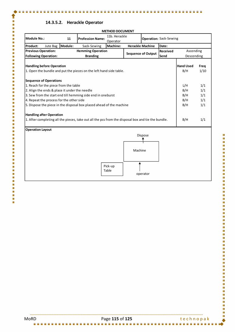
MoRD Page 115 of 125 t e c h n o p a k
14.3.5.2. Herackle Operator
11 Profession Name: Operation:
Product: Jute Bag Module: Sack-Sewing Machine: Date:
Received
Send
Handling before Operation Hand Used Freq
1. Open the bundle and put the pieces on the left hand side table. B/H 1/10
Sequence of Operations
1. Reach for the piece from the table L/H 1/1
2. Align the ends & place it under the needle B/H 1/1
3. Sew from the start end till hemming side end in oneburst B/H 1/1
4. Repeat the process for the other side B/H 1/1
B/H 1/1
Handling after Operation
1. After completing all the pieces, take out all the pcs from the disposal box and tie the bundle. B/H 1/1
Operation Layout
Ascending
Following Operation: Branding Descending
METHOD DOCUMENT
Module No.:11b. Herackle
OperatorSack-Sewing
Herackle Machine
5. Dispose the piece in the disposal box placed ahead of the machine
operator
Previous Operation: Hemming OperationSequence of Output
Machine
Pick-upTable
Dispose

MoRD Page 116 of 125 t e c h n o p a k
14.3.5.3. Branding Operator
11 Profession Name: Operation:
Product: Jute Bag Module: Sack-Sewing Machine: Date:
Received
Send
Handling before Operation Hand Used Freq
1. Carrying the Bag from the Sewing section to the Branding section. B/H 1/10
Sequence of Operations
1. Take the jute bag with both hands. B/H 1/1
2. Place the print screen on the bag with both the hands. B/H 1/1
3. Adjust the bag finally with both the hands so that the print takes place properly. B/H 1/1
B/H 1/1
B/H 1/1
6. Segregate/Rectify any defect on the cloth. B/H 1/1
Handling after Operation
1. Disposal of the cloth to the Packing Department in the barrow. B/H 1/1
Operation Layout
Ascending
Following Operation: Bundling Descending
METHOD DOCUMENT
Module No.:11c. Branding
OperatorSack-Sewing
NA
5. Watch the bag very carefully to check the occurrence of any printing defect.
Previous Operation: Herackle OperationSequence of Output
4. Remove the print screen with both hands.
Print Screen Machine
Branding Operator
Jute Bag Barrow
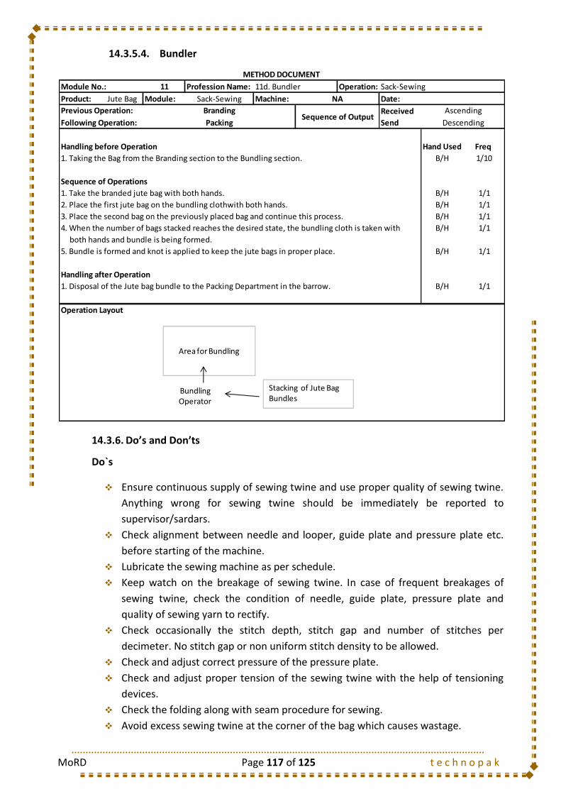
MoRD Page 117 of 125 t e c h n o p a k
14.3.5.4. Bundler
14.3.6. Do’s and Don’ts
Do`s
Ensure continuous supply of sewing twine and use proper quality of sewing twine.
Anything wrong for sewing twine should be immediately be reported to
supervisor/sardars.
Check alignment between needle and looper, guide plate and pressure plate etc.
before starting of the machine.
Lubricate the sewing machine as per schedule.
Keep watch on the breakage of sewing twine. In case of frequent breakages of
sewing twine, check the condition of needle, guide plate, pressure plate and
quality of sewing yarn to rectify.
Check occasionally the stitch depth, stitch gap and number of stitches per
decimeter. No stitch gap or non uniform stitch density to be allowed.
Check and adjust correct pressure of the pressure plate.
Check and adjust proper tension of the sewing twine with the help of tensioning
devices.
Check the folding along with seam procedure for sewing.
Avoid excess sewing twine at the corner of the bag which causes wastage.
11 Profession Name: Operation:
Product: Jute Bag Module: Sack-Sewing Machine: Date:
Received
Send
Handling before Operation Hand Used Freq
1. Taking the Bag from the Branding section to the Bundling section. B/H 1/10
Sequence of Operations
1. Take the branded jute bag with both hands. B/H 1/1
2. Place the first jute bag on the bundling clothwith both hands. B/H 1/1
3. Place the second bag on the previously placed bag and continue this process. B/H 1/1
B/H 1/1
both hands and bundle is being formed.
B/H 1/1
Handling after Operation
1. Disposal of the Jute bag bundle to the Packing Department in the barrow. B/H 1/1
Operation Layout
Ascending
Following Operation: Packing Descending
METHOD DOCUMENT
Module No.: 11d. Bundler Sack-Sewing
NA
5. Bundle is formed and knot is applied to keep the jute bags in proper place.
Previous Operation: BrandingSequence of Output
4. When the number of bags stacked reaches the desired state, the bundling cloth is taken with
Area for Bundling
Bundling Operator
Stacking of Jute Bag Bundles

MoRD Page 118 of 125 t e c h n o p a k
Don`ts
Do not allow stitch gap or non uniform stitch density.
Do not use worn out needle or pressure plate
Do not use improper quality of sewing twine.
Do not run sewing machine with loose needle, looper plate or misaligned needle
and looper.
Do not waste sewing twine.
Do not run sewing machine without material.
14.4. Types of Mazdoor
S. No. Mazdoor Type Job Description
1 Sewing Mazdoor Carries the Stitched jute bag from Stitching section to Branding and Bundling section
14.5. Training Gantt Chart
Training Days Required
Class Room Training Shop Floor Training
9 Days 18 Days
1 2 3 4 5 6 7 8 9
14.1 Introduction
14.2 Objective
14.3 Sack Sewing Machine
14.3.1 Types of Machines
14.3.2 Types of Stitch
14.3.3 Types of Seam
14.3.4 Sewing Defects of Jute Bags: Causes and Remedial
Measures
14.3.5 Method Study
14.3.5.1 Hemming Operator
14.3.5.2 Herackle Operator
14.3.5.3 Branding Operator
14.3.5.4 Bundler
14.3.6 Do's and Don'ts
14.4 Types of Mazdoor
1 2 3 4 5 6 7 8 9 10 11 12 13 14 15 16 17 18
14.1 Introduction
14.2 Objective
14.3 Sack Sewing Machine
14.3.1 Types of Machines
14.3.2 Types of Stitch
14.3.3 Types of Seam
14.3.4 Sewing Defects of Jute Bags: Causes and Remedial
Measures
14.3.5 Method Study
14.3.5.1 Hemming Operator
14.3.5.2 Herackle Operator
14.3.5.3 Branding Operator
14.3.5.4 Bundler
14.3.6 Do's and Don'ts
14.4 Types of Mazdoor
MODULE 11 : SACK-SEWING
I. CLASSROOM TRAINING
II. SHOP-FLOOR TRAINING
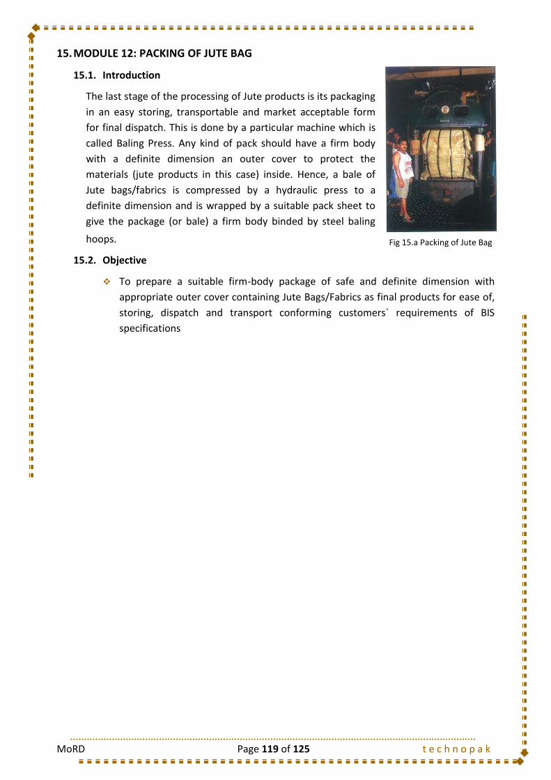
MoRD Page 119 of 125 t e c h n o p a k
15. MODULE 12: PACKING OF JUTE BAG
15.1. Introduction
The last stage of the processing of Jute products is its packaging
in an easy storing, transportable and market acceptable form
for final dispatch. This is done by a particular machine which is
called Baling Press. Any kind of pack should have a firm body
with a definite dimension an outer cover to protect the
materials (jute products in this case) inside. Hence, a bale of
Jute bags/fabrics is compressed by a hydraulic press to a
definite dimension and is wrapped by a suitable pack sheet to
give the package (or bale) a firm body binded by steel baling
hoops.
15.2. Objective
To prepare a suitable firm-body package of safe and definite dimension with
appropriate outer cover containing Jute Bags/Fabrics as final products for ease of,
storing, dispatch and transport conforming customers` requirements of BIS
specifications
Fig 15.a Packing of Jute Bag
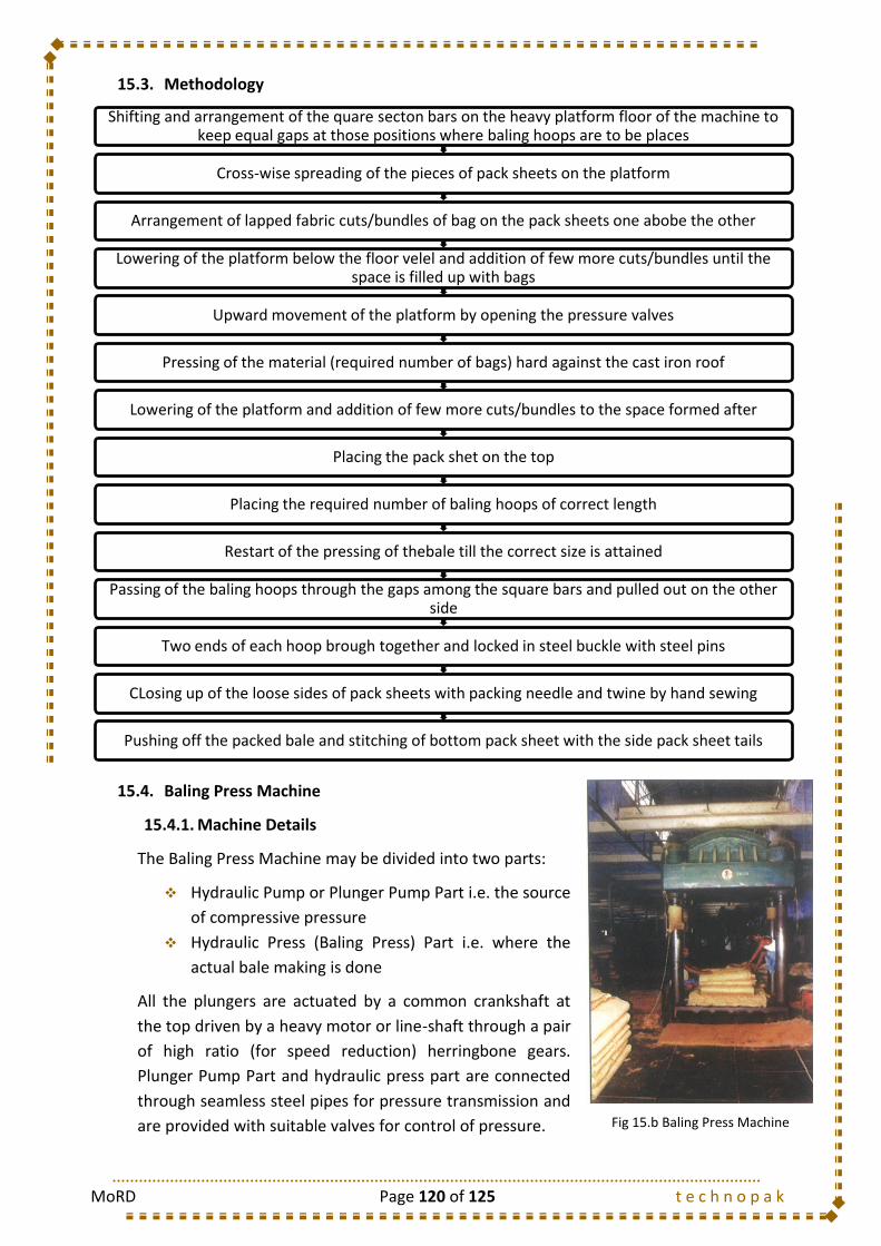
MoRD Page 120 of 125 t e c h n o p a k
15.3. Methodology
15.4. Baling Press Machine
15.4.1. Machine Details
The Baling Press Machine may be divided into two parts:
Hydraulic Pump or Plunger Pump Part i.e. the source
of compressive pressure
Hydraulic Press (Baling Press) Part i.e. where the
actual bale making is done
All the plungers are actuated by a common crankshaft at
the top driven by a heavy motor or line-shaft through a pair
of high ratio (for speed reduction) herringbone gears.
Plunger Pump Part and hydraulic press part are connected
through seamless steel pipes for pressure transmission and
are provided with suitable valves for control of pressure.
Shifting and arrangement of the quare secton bars on the heavy platform floor of the machine to keep equal gaps at those positions where baling hoops are to be places
Cross-wise spreading of the pieces of pack sheets on the platform
Arrangement of lapped fabric cuts/bundles of bag on the pack sheets one abobe the other
Lowering of the platform below the floor velel and addition of few more cuts/bundles until the space is filled up with bags
Upward movement of the platform by opening the pressure valves
Pressing of the material (required number of bags) hard against the cast iron roof
Lowering of the platform and addition of few more cuts/bundles to the space formed after
Placing the pack shet on the top
Placing the required number of baling hoops of correct length
Restart of the pressing of thebale till the correct size is attained
Passing of the baling hoops through the gaps among the square bars and pulled out on the other side
Two ends of each hoop brough together and locked in steel buckle with steel pins
CLosing up of the loose sides of pack sheets with packing needle and twine by hand sewing
Pushing off the packed bale and stitching of bottom pack sheet with the side pack sheet tails
Fig 15.b Baling Press Machine
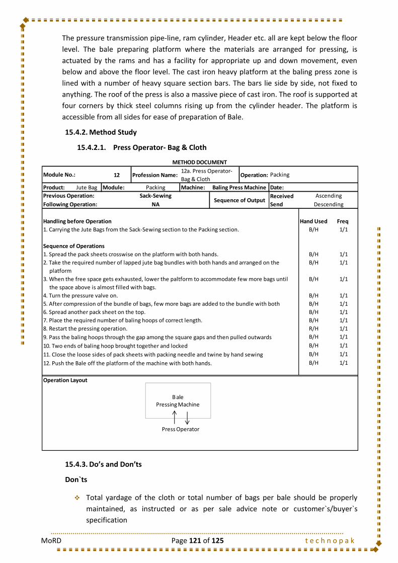
MoRD Page 121 of 125 t e c h n o p a k
The pressure transmission pipe-line, ram cylinder, Header etc. all are kept below the floor
level. The bale preparing platform where the materials are arranged for pressing, is
actuated by the rams and has a facility for appropriate up and down movement, even
below and above the floor level. The cast iron heavy platform at the baling press zone is
lined with a number of heavy square section bars. The bars lie side by side, not fixed to
anything. The roof of the press is also a massive piece of cast iron. The roof is supported at
four corners by thick steel columns rising up from the cylinder header. The platform is
accessible from all sides for ease of preparation of Bale.
15.4.2. Method Study
15.4.2.1. Press Operator- Bag & Cloth
15.4.3. Do’s and Don’ts
Don`ts
Total yardage of the cloth or total number of bags per bale should be properly
maintained, as instructed or as per sale advice note or customer`s/buyer`s
specification
12 Profession Name: Operation:
Product: Jute Bag Module: Packing Machine: Date:
Received
Send
Handling before Operation Hand Used Freq
1. Carrying the Jute Bags from the Sack-Sewing section to the Packing section. B/H 1/1
Sequence of Operations
1. Spread the pack sheets crosswise on the platform with both hands. B/H 1/1
2. Take the required number of lapped jute bag bundles with both hands and arranged on the B/H 1/1
platform
3. When the free space gets exhausted, lower the paltform to accommodate few more bags until B/H 1/1
the space above is almost filled with bags.
4. Turn the pressure valve on. B/H 1/1
B/H 1/1
B/H 1/1
7. Place the required number of baling hoops of correct length. B/H 1/1
8. Restart the pressing operation. R/H 1/1
B/H 1/1
B/H 1/1
B/H 1/1
B/H 1/1
Operation Layout
METHOD DOCUMENT
Module No.:12a. Press Operator-
Bag & ClothPacking
Baling Press Machine
Previous Operation: Sack-SewingSequence of Output
Ascending
Following Operation: NA Descending
5. After compression of the bundle of bags, few more bags are added to the bundle with both
6. Spread another pack sheet on the top.
9. Pass the baling hoops through the gap among the square gaps and then pulled outwards
10. Two ends of baling hoop brought together and locked
11. Close the loose sides of pack sheets with packing needle and twine by hand sewing
12. Push the Bale off the platform of the machine with both hands.
B ale Pressing Machine
Press Operator

MoRD Page 122 of 125 t e c h n o p a k
Also, the number of bags per bundle and No. of bundles per Bale should be
maintained as per instruction/specification
Baling of hoop of prefixed length as per quality (to be baled) should be made
readily available near the machine
Ensure correct quality of fabric or bags to be packed in each bale. In the same bale,
different quality of bags or fabrics should not be put together.
Total number of fabric cuts as well as number of short cuts (allowable) per bale
should be as per B.I.S specifications.
Hand sewing twine for sewing bale cover should be of good quality and as per
specification, so that it does not tear or fails afterwards.
Specified packing allowance is to be followed. Correct pressure for bale
preparation is to be controlled accordingly.
Weight of bale is to be maintained by adjusting and mixing heavy/light bundles of
bags or cuts of fabric in one bale. Ensure it.
The dimension of the bale should be properly known. Accordingly volume
measurement should be properly done by suitable adjustment of pressure and
correct hoop length.
Don`ts
Do not over press any bale
Do not use short hoop length for any reason
Do not mix up different quality of bags or bundles or cuts in a bale.
Do not accept inferior quality pack sheet or hand sewing twine.
Do not give excess number of joined bags or short cuts over the limit permissible.
Do not prepare under weight or excessive over weight bales.
Do not keep pressure arrangement running in empty bale-press machine.
Do not exceed packing allowance limit for any reason.
15.5. Types of Mazdoor
S. No. Mazdoor Type Job Description
1 Packing Mazdoor Carries the Jute Fabrics to the Packing Department from Sewing Department
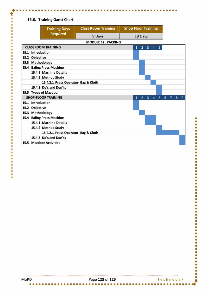
MoRD Page 123 of 125 t e c h n o p a k
15.6. Training Gantt Chart
Training Days Required
Class Room Training Shop Floor Training
9 Days 18 Days
1 2 3 4 5
15.1 Introduction
15.2 Objective
15.3 Methodology
15.4 Baling Press Machine
15.4.1 Machine Details
15.4.2 Method Study
15.4.2.1 Press Operator- Bag & Cloth
15.4.3 Do's and Don'ts
15.5 Types of Mazdoor
1 2 3 4 5 6 7 8 9
15.1 Introduction
15.2 Objective
15.3 Methodology
15.4 Baling Press Machine
15.4.1 Machine Details
15.4.2 Method Study
15.4.2.1 Press Operator- Bag & Cloth
15.4.3 Do's and Don'ts
15.5 Mazdoor Activities
MODULE 12 : PACKING
I. CLASSROOM TRAINING
II. SHOP-FLOOR TRAINING

MoRD Page 124 of 125 t e c h n o p a k
16. MODULE 13: MAZDOOR
16.1. Objective
The objectives of Mazdoors in the Jute Mill are:
To carry the material from one section to other in the Jute processing line
To maintain the cleanliness in the Jute Mill
To inform supervisor on the occurrence of any problem in the respective
department
16.2. Types of Mazdoor
S. No. Mazdoor Type Job Description
1 Jute Bale Unloading Mazdoor
Unloading of the Jute Bales from the truck
2 Jute Bale Handling Mazdoor
Stacks the Jute Bales in the Barrow sequentially
3 Jute Morah Carrying Mazdoor
Carries the Jute Morahs after Selection to the Batching Department
4 Jute Piling Mazdoor Carries the Jute Morahs after Selection to the Piling Zone
5 Carrier Carries the Jute Morahs after Piling to the Carding Department
6 Can Mazdoor Shifts the Jute Sliver Cans to different zone as per requirement
7 Spinning Bobbin Carrying Mazdoor (Bobbin Carrier)
Carries the Spinning bobbin from Spinning Department to Winding Department and Bring back the empty bobbins from Winding Department to Spinning Department
8 Spool Mazdoor Carrying the Spool packages from Winding Department to Twisting/Beaming Department
9 Cop Mazdoor Carrying the Cop packages from Winding Department to Weaving Department
10 Beaming Mazdoor Unloads the heavy warp beam and carries to the Weaving Department
11 Weaving Mazdoor Carries the empty shuttles from Shuttle issue Department to Weaving Department
12 Beam Carrier Carries the weaver`s Beam from Weaving Department to Finishing Department
13 Cloth Carrier Carries the Jute cloth/rolls from one process to another in Finishing department
14 Sewing Mazdoor Carries the Stitched jute bag from Stitching section to Branding and Bundling section
15 Packing Mazdoor Carries the Jute Fabrics to the Packing Department from Sewing Department

MoRD Page 125 of 125 t e c h n o p a k
16.3. Training Gantt Chart
1 2
Jute: An Introduction
Jute Manufacturing Process
Types of Jute
Types of Mazdoor
1 2 3
Jute: An Introduction
Jute Manufacturing Process
Types of Jute
Mazdoor Activities
MODULE 13 : MAZDOOR
I. CLASSROOM TRAINING
II. SHOP-FLOOR TRAINING