trailmaster 300 xrx user parts manual - bmikarts.com manuals/300 xrx... · an open-face helmet...
TRANSCRIPT


CONLENTS
,OWNER S MANUAL
1. FOREWORD 1
2. A FEW WORDS ABOUT SAFETY 2
3. IMPORTANT SAFETY INFORMATION 3
4. SAFETY LABELS 5
5. ARE YOU READY TO DRIVE? 6
6. IS YOUR VEHICLE READY TO DRIVE? 7
7. SAFE DRIVING PRECAUTIONS 8
8. P.D.I. 10
9. SPECIFICATIONS 11
10. OPERATION 13
11. SERVICE INSTRUCTIONS 17
12. REPAIR 20
13. PERIODICAL CHECK AND SERVICES 23
14.WIRING DIAGRAM 24
Page

1
.
Thank you for purchasing our Kart. We hope you will enjoy it. Before you Start to operate the kart, please read through this Owner s Manual carefully as it contains important safety and maintenance information. Failure to follow the warnings contained in this manual can result in serious injuries. Or death
Be sure to follow the recommended maintenance schedule and service your kart accordingly. Preventive maintenance is extremely important to the longevity of your kart.
Beginners should seek instruction from their dealer or qualified instructors before and during initial use of the kart. It is also recommended to practice in a large flat open area to familiarise yourself with operations of this kart.
We hope you will have a pleasant experience with out products and thank you again for choosing our kart.
FOREWORD

AFEW WORDS ABOLLT SAFETY
In order to keep everyone safe, you must take responsibility for the safe operationof your kart.
To help you make informed decisions about safety, we have provided operatingprocedures and other information on labels and in this manual. This information alertsyou to potential hazards that could hurt you or others.
It is not practical or possible to warn you about all hazards associated withoperating or maintaining a kart. You must use your own good judgment.
You will find important safety information in a variety of forms, including:Safety Labels - On the kart.
Safety Messages - preceeded by a safety alert symbol and one of two signalwords: WARNING, or CAUTION.
These signal words mean:
WARNING
Physical harm may result from failure to adhere to the instructions that are described within the WARNING labels.
Safety Headings - such as Important Safety Reminders or Important Safety Precautions.
Safety Section - such as Kart Safety.
Instructions - how to use this kart correctly and safely.
This entire manual is filled with important safety imformation-please read it all carefully.
2

IMPORTANT SAFETY INFORMATION
Your kart will provide you with many years of use and pleaseur. Providing youtake responsibility for your own safety and that of any one else using your kart ornear to the kart when it is being used and understand the challenges you can meetwhile driving.
There is much that you can do to protect yourself while operating your kart. You willfind many helpful recommendations throughout this manual. The following are afew that we consider to be the most important.
Follow the Age Recommendation The kart should not be driven by anyone under the age of 16.
Always Wear a Helmet It,s a proven fact: helmets significantly reduce the number and severity of head injuries.Always wear an approved motorcycle helmet. We also recommend that you wear eyeprotection, sturdy boots, gloves, and other protective gear.
Drive Off-Road Only Your kart is designed and manufactured for off-road use only. The tires are notmade for use on pavements, and the kart does not have turn signals and other featuresrequired for use on public roads. If you need to cross a paved or public road, get off andwalk your kart across.
Take Time to Learn & Practice Even if you have driven other karts, take time to become familiar with how this kartworks and handles. Practice in a safe area until you build your skills and get accustomed
,to this kart s size and weight. Because many accidents involve inexperienced or untrained drivers, we urge all driversto take a training course. Check with your dealer for more information on training courses.
Be Alert for Off-Road Hazards The terrain can present a variety of challenges when you drive off-road. Continually
read the terrain for unexpected turns, drop-offs, rocks, ruts, and other hazards. Alwayskeep your speed low enough to allow time to see and react to hazards.
3

IMPORTANT SAFETY INFORMATION
Drive within Your Limits Pushing limits is another major cause of kart accidents. Never drive beyond yourpersona l abilities or faster than conditions warrant. Remember that alcohol, drugs, fatigue,and inattention can significantly reduce your ability to make good judgments and drivesafely.
,Dno t Drink and drive, Alcohol and driving don t mix. Even one drink can reduce your ability to respond to
changing conditions, and your reaction time gets worse with every additional drink. So, ,don t drink and drive, and don t let your friends drink and drive either.
Do not operate this kart at night., Openating in the dark visinon can greatly reduce a driver s visibility and judgment. So driving
at night is dangerous and can increase the possibility for an accident.
Never run your kart indoors. The exhaust from the engine contains a tasteless, odorless and poisonous gas calledcarbon monoxide.
Keep away from moving parts of the kart The operator of the kart should never place their hands or other parts of their bodynear any moving part of the kart. Failure to adhere to this warning will cause physicalharm to your body.
Skidding or Sliding T he ter rain s urface can be a major factor affecting turns. Skidding in a turn is more likely tooccur on slippery surfaces such as snow, ice, mud and loose gravel. If you skid on ice, youmay lose all directional control. To avoid skidding on slippery terrain, keep your speed lowand drive carefully.
4

WA
RN
ING
CA
UTIO
N
3031
105
Seat B
elt Mu
st Be W
om At
All Tim
esTH
IS V
EHIC
LE M
ANUF
ACTU
RED
FOR
OFF-
ROAD
USE
ONL
Y.DO
NO
T O
PERA
TE O
N PU
BLIC
STRE
ETS,
ROAD
S OR
HIG
HWAY
S.
SAFETY L ABELS
This section presents some of the most important information and recommendations to helpyou drive your kart safely. Please take a few moments to read these pages.
The labels should be considered permanent parts of the kart. If a label comes off or becomes hard to read, contact your dealer for a replacement.
WARNING
NO LONG
HAIR
ALL HAIR MUST BE TIED UP ANDSECURED AT OR ABOVE SHOULDER
LENGTH.ALL LOOSE CLOTHING MUST BESECURED.ALL NECKLACES AND
SCARNES MUST BESECURED.
WARNING
THIS GO-KART CAN BE HAZARDOUS TO OPERATEif driven carelessly.
IN JURIES can result if you do not follow theseinstructions:
,READ OWNERS M ANUAL AND ALL LABELS BEFOREYOU OPERATE THIS GO-KART.
NEVER OPERATE THIS GO-KART WITHOUT PROPERINSTRUCTIONS.Beginners require adultsupervision.
NEVER OPERATE THIS GO-KART ON PUBLIC ROADS.It is intended for off-road use only.
ALWAYS WEAR AN APPROVED MOTORCYCLE HELMET.eye protection and protective clothing.
NEVER OPERATE THIS GO-KART AT EXCESSIVESPEEDS.You increase your risk of losing control ifyou operate it at speeds too tast for the terrain,visibility ocnditions or your experi3wence.
NEVER ATTEMPT WHEELIES,JUMPS,OROTHER STUNTS.
303115
WARNING3031107
Loss of c ontrol, collision,or getting caught in moving parts
can result in serious injuries.Not to be operated by person under 16 years old
Wear a D.O.T. approved motorcycle helmetSecure long hair and loose clothingwear protective eye wear and clothingkeep arms,legs and feet inside kart
Do not use alcohol or drugs
WARNINGYOUR ENGINE IS WATER COOLED!YOU MUST CHECK THE RADIATOROFTEN TO SEE IF THE LEVEL OFTHE COOLENT IS FULL. IF NOT,REFILL AS NEEDED. IF YOU DONOT DO THIS ,YOUR ENGINECOULD BURN UP AND COSTYOU IN REPAIRS.
NEVER OPEN THE RADIATORCAP WHEN ENGINE IS RUNNING.ALLOW THE ENGINE TO COOLDOWN!
WA
RN
ING
NO
RID
ING
WARNING
ALWAYS CHECK GEAR CASEOIL AND REPLACE ASNEEDED . IF NOT DOINGSO.YOU TAKE THE CHANCE OF BURNINGTHE GEARS UP ANDCOSTLY REP AIRS.
WARNINGDo not sh i f t gears when the veh ic le is in mot ion or i tmight cause damage to the t ransmiss ion and vo idwarranty .sh i f t on lu whenthe foot brake is fu l lyengaged and the veh ic le is a t a comple te s top .
WARNING OIL CHECKAFTER RUNNING YOUR KART EVERY 4HOURW..YOU NEED TO CHECK YOURENGINE/GEAR BOX OIL FAILURE TODO SO CAN CAUSE ENGINE DAMAGE
COOLENT CHECKAFTER RUNNING YOUR KART EVERY 5HOURW..YOU NEED TO CHECK YOURCOOLENT FLUID.FAILURE TO DO SOCAN CAUSE ENGINE DAMAGE.NEVERCHECK YOUR COOLENT WHEN ENNGINEIS RUNNING ALWAYS ALLOW ENGINETO COOL DOWN BE FOR CHECKING
5

ARE YOU READY TO DRIVE?
Before each drive, you need to make sure that you and your kart are both ready to drive.To help get you prepared, this section discusses how to evaluate your driving readiness, whatitems you should check on your kart, and adjustments to make for your confort, convenience,of safety.
Before you drive your kart for the first time, we urge you to:, Read this owner s manual and the labels on your kart carefully.
Make sure you understand all the safety messages. Know how to operate all the controls.
Before each drive, be sure: You wear your seat belt at all times while driving your kart. You feel well and are in good physical and mental condition. You are wearing an approved motorcycle helmet(with chin strap tightened securely),eye protection, and other protective clothing.
, You don t have any alcohol or drugs in your system.
Protective Apparel For your safety, we strongly recommend that you always wear an D.O.T. Approved motorcyclehelmet, eye protection, boots, gloves, long pants, and long-sleeved shirt or jacket wheneveryou drive. Aothough complete protection is not possible, wearing proper gear can reduce the chance ofinjury should you have an accident. The following suggestions will help you choose the proper protective gear.
Helmets and Eyes Protection Your helmet is your most important piece of protective gear because it offers the bestprotect ion against hea d injuries. A helmet should fit your head comfortably and securely. An open-face helmet offers some protection, but a full-face helmet offers more. Regardlessof the style, look for a D.O.T. (Department of Transportation) sticker on any helmet you buy.Always wear a face shield or goggles to protect your eyes and help your vision.
Operating this kart without wearing an approved motorcycle helmet, eye protection,and protective clothing could increase your chances of head and/or eye injury, and thepossibility of death in the event of a severe accident.Always wear an approved motorcycle helmet that fits properly and wear eye protection(goggles or face shield), gloves, boots, long-sleeved shirt or jacket and long pants.
6
WARNING

ARE YOU READY TO DRIVE?
IS YOUR VEHICLE READY TO DRIVE?
Additional Driving Gear In addition to a helmet and eye protection, we also recommend: Sturdy off-road motorcycle boots to help protect your feet, ankles, and lower legs. Off-road motorcycle gloves to help protect your hands. Driving pants with knee and hip pads, a driving jersey with padded elbows, and a chest/shoulder protector.Driver Training Developing your driving skills is an on-going process. Even if you have driven other karts,before take time to become familiar with how this kart works and handles. Practice driving the kart in a safe area to develop your skills. Do not drive on rough terrain until you get accus-
,tomed to the kart s controls, and feel comfortable with its size and weight.
No Alcohol or Drugs, Alcohol, drugs and karts don t mix. Even a small amount of alcohol can impair your ability
to operate a kart safely. Likewise, drugs-even if prescribed by a physician-can be dangerouswhile operating a kart. Consult your doctor to be sure it is safe to operate a vehicle aftertaking medication.
Before each drive, it is important to inspect your kart and make sure any problems you find are corrected. A pre-drive inspection is a must, not only for safety, but because having a breakdown,or even a flat tire, can be a major inconvenience. If you r kart has ove rturned or has been involved in a collision, do not drive it until your kart has been inspected by your dealer. There may be damage or other problems that you can not see.
Operating this kart without your seat belt could cause you to be thrownfrom the kart, causing serious injury or death.
Operating this kart after consuming alcohol or drugs can seriously affect yourjudgment, cause you to react more slowly, affect your balance and perception, andcould result in serious injury or death. Never consume alcohol or drugs before or while operating this kart.
Improperly malntaining this kart or failing to correct a problem before driving cancause a crash in which you can be seriously hurt or killed. Always perform a pre-drive inspection before every drive and correct any problems.
7
WARNING
WARNING
WARNING
Pre-Drive Inspection Always carry out the Pre-Drive Inspection detailed on Page 16 before getting in your kart.

Control Speed Driving at excessive speed increases the chances of an accident. In choosing an appropriatespeed, you need to consider the capability of your kart, the terrain, visibility and other operatingconditions, plus your own skill and experience.
SAFE DRIVING PRECAUTIONS
Off-Road Use Only Your kart and its tires are designed and manufactured for off-road use only, not for use onpaved surfaces. Driving on paved surfaces can affect the kart handling and control.You sho-uld not drive
When driving off-road, also remember to always obey local off-road driving laws andregulations. Obtain permission to drive on private property. Avoid posted areas and obey
no trespassing signs. You should never drive your kart on public streets, roads or highways, even if they are notpaved. Drivers of street vehicles may have difficulty seeing and avoiding you, which couldlead to a collision.In many states it is illegal to operate karts on public streets,roads and highways.
Keep Hands and Feet on Controls When driving your kart, always keep both hands on the steering wheel and both feeton the foot controls. It is important to maintain your belance and to control the kart.Removing hands or feet away from the controls can reduce your ability to react andcontrol the kart.
Operating this kart on paved surfaces may seriously affect handling and control ofthe kart, and may cause the vehicle to go out of control. Never operate the kart on any paved surfaces, including pavements, driveways, carparks and streets.
Operating this kart on public streets, roads or highways could cause acollision with another vehicle. Never operate this kart on any public streets, roads or highways, whetherthey are dirt, gravel or paved surfaces.
Removing your hands from the steering wheel or feet from the foot controls duringoperation can reduce your ability to control the kart or could cause you to lose yourbalance and fall off the kart. Always keep both hands on the steering wheel and both feet on the foot controlsof your kart during operation.
WARNING
WARNING
WARNING
WARNING Operating this kart at excessive speeds increases your chances of losingcontrol of the kart, which can result in an accident. Always drive at a speed that is appropriate for your kart, the terrain, visibilityand other operating conditions, and your experience.
8

Use Kart on Unfamiliar or Rough Terrain, Before driving in a new area, always check the terrain thoroughtly, Don t drive fast on
,unfamil iar terrain or when vis ibility is limited (it s sometimes difficult to see obstructionslike hidden rocks, bumps, or holes in time to react).
Never drive past the limit of visibility. Maintain a safe distance between your kart andother off-road vehicles. Always exercise caution and use extra care on rough, slipperyand loose terrain.
Do Not Perform StuntsYou should always operate your kart in a safe and reasonable manner. When driving,always keep all four wheels on the ground.
Failure to use extra care when operating this kart on unfamiliar terraincould result in the kart overturning or going out of control. Go slowly and be extra careful when operating on unfamiliar terrain. Alwaysbe alert to changing terrain conditions when operating the kart.
Failure to use extra care when operating on excessively rough, slippery orloose terrain could cause loss of traction or vehicle control, which could resin an accident, including an overturn. Do not operate on excessively rough, slippery or loose terrain until you havelearned and practiced the skills necessary to control the kart on such errain. Always be especially cautious on these kinds of terrain.
Attempting wheelies, jumps, and other stunts increases the chance of anaccident, including an overturn.
, Never attempt stunts, such as wheelies or jumps. Don t try to show off.
9
SAFE DRIVING PRECAUTIONS
WARNING
WARNING
WARNING
Radiator Indicator Lamp During the driving, you should always keep closecontact with this red indicator lamp.This indicator lamp will tell you when your engine coolent system is getting too hot.Tokeep from causing any damage, you should stop the kart and turn the key off. Check ifthere is any leak, At this time do not open the radiator cap,allow your coolent system and engine to cool down before opening th e radiator cap. If you find the coolent completely gone,you shoule check if the radiator,hoses or enginehas stch leaks

P.D.I.
A. Install RR. Shocks and tighten the unts.B. Install Ball Head, Tie Rod, tighten the Castle Nut and insert the cotter Pin.C. In stall Dust Seals, align the Ball Head Bolt, Knuckle Support to the square hole on the Lower A-Arm.D. Install Flange Nut and tighten it (>88.9 foot lbs)E. Install Front Tires and tighten the nuts.F. Install Rear Tires, tighten the nuts, insert cotter Pin and put on the Rubber Cover.G. Raise the C.B.C bar as the picture shows.H. Install C.B.C bar RR., put on R-Washer.I. Install Head-Rest.J. Check all nuts and bolts, wiring, cables, fuel line, switches and tire pressure.K. Fill battery with Acid and charge, check and fill the engine with the recommended oil.L. Fill fuel tank with Unleaded Gasoline, and turn on the ignition switch to start the engine.
10

Overall Length 87 in.(2210mm)Overall Width 53.5 in.(1346mm)Overall Height 56.6 in.(1438mm)Wheelbase 66.1 in.(1680mm)Front Track 45.7in.(1160mm)Rear Track 42.7 in.(1085mm)Ground Clearance 8.5 in.(215mm)
DIMENSIONS
ENGINE
CAPACITIES
Type Water-cooled.4-StrokeEngine capacity 300ccBore / Stroke 72.5mm x 66.8mmDisplacement 275.6cmCorrected compression ratio 10:1Carburetor VEKS4 & CV30Output Power 13KW/ 6500RPMMaximum Torque 22N.m/5000RPMStarting ElectriIgnition C.D.ILubrication Force&SplashTransmission Automatic(C.V.T system)Spark Plug DR8EA(NGK)Plug gap 0.6-0.7mmFuel Type Rq90(unleaded)Lubricate oil SAE 15W -40/SF
Maximum load Do Uble Seats/400lbsFuel tank 25 GalEngine oil 30 OzStarting 5s
o oClimbing 20 -25Battery 12V 10AhHead Light 12V 35W /35WTail Light 12V 21W /5WFuse 10A
11
SPECIFICATIONS
DRIVE COMPONENTSGear box oil MoS2 & W -2DW-4D

Brake Track <7m@20miles/hTop speed 75miles/h(or limited as customers require)
CHASSIS
TIRE PRESSURE
WEIGHT
Front,Rear brake Hydraulic disc,left foot controlFront tire 20 x 7-8Rear tire 22 x 10-10Front Suspension Independent Dual A-ArmRear Suspension Full Independet Rear Suspension/ Oil Damped ShockRestraint System Dual 4-point HarnessFinal Drive CV- Shafts
Front 7-9psiRear 8-9psi
Net Weight 280KgGross Weight 320Kg
12

OPERATION
A. Operation controls WARNING - Do not attempt to start or operate the engine until completely familiar with the locatio n and use of each control necessary to operate this vehicle. The operatormust know how to stop this machine before starting and driving it.
a. Throttle The right foot pedal is the throttle that controls the kart speed. As the engine speed incre-ases above idle, the clutch automatically engine and moves the vehicle forward.(See Fig. 1)
Each time prior to starting the engine, check the throttle assembly to ensurethat when the pedal is pushed all the way forward the assembly is workingsmoothly and returns to idle when released. Do not operate if pedal or engine throttlelinkage fail to return to idle. If unable to correct the problem through lubrication,adjustment or replacement of worn parts, contact your dealer for assistance.
b. Brake The brake is the left foot pedal (See Fig.1). Applying pressure to the pedal slows orstops the kart.
c. Start engine Insert the key into key-switch, turn the key clockwise, release the key when the engine starts. The engine will warm up within 5 minutesand the choke will close autom-atically allowing operation at
,normal RPM(Warning: Don t crank the starter for more than 5 seconds at one time).
d. Engine stop button Important-stop button teat. Before driving this vehicle, test the EngineStop Button to ensure that it is operating properly. With the engine running, push andhold the Engine Stop Button for two seconds for the engine to shut down.
13
Figure 1 BRAK PEDAL
REVERSE LEVER
THROTTLE PEDAL
ENGINE STOP BUTTON
SMITCH UNT WINKER
HORN BUTTON
POWER OUTER
LIGHT SWITCHMETER
GNITION START SNITCH
PARKING BRAKE
WARNING

OPERATION
B. Pre-Drive Inspection
Perform this pre-drive inspection everyday before driving the vehicle. If not
performed, serious damage to the vehicle or personal injury may result.
Check the engin e oil level is between the bottom of the dipstick and the 0 mark, Checkfor leaks. Add oil if required.Check the Fuel Level. Add fuel as necessary and do not overfill. Check for leaks. Ensurethe fuel filler cap is securely fastened. Check the Brakes. Depress the left brake pedal several times, and check for adequate brakepedal free play. Make sure there is no brake fluid leakage.Check the tires. Check their condition for damage or excessive wear and pressure. Check the Throttle Chain. Check for smooth operation.Ensure the throttle snaps backto idle when released and moves smoothly without sticking.Check the Engine Stop Button. While the engine is running press and hold the engine stopbutton for 2 seconds. Make sure the engine stops.Check all Nuts, Bolts, and Fasteners. Check the wheels to see that all axle nuts and lug nutsare tightened properly. Check and tighten as necessary all other nuts, bolts and fasteners.Check the C.B.C.Bar. Ensure all C.B.C bars are in place before operating the kart.Check the Lights. Check the headlights, brake light and tail light are all working.Check the Steering. Check that the steering wheel moves freely in both directions butwithout any unusual looseness.Check all Cable Housings. Check these for wear and the fitting for any looseness.Check the under body and exhaus t system. Remove all dirt, vegetation and mud and checkfor any damage due to impact with rocks or unever terrain.Check the Air Cleaner Housing Drain Tube. Check the deposits in the drain tube. If necessary,check the tube and air cleaner housing.Check Leaks and Loose Parts. Walk around your kart and look for anything that appearsunusual, such as a leak or loose cable.Check the Parking Brake. Make sure the kart does not move forward or backward whenthe parking barke is applied.Chech the Radiator.Make sure there is no leak of radiator or hoses before you start the engine.Check the water level.Check the radiator to see if the level of the coolent is full.Refill the coolent as needed oryour engine would burn up and cost you in repairs.Never open the radiator cap whenengine is running.Allow the engine to cool down,and the refill the coolent.
a.
b.
c.
d.e.
f.
g.
i.
i.j.k.
l.m.
n.
o.
p.
q.
14
WARNING

STEERING WHEEL
HORN NUITS
TANK COMP.FUEL
REAR CAPGO PACK
Figure 2
SEAT BELT
MIRROR
FLAG POLE BRACKER
FUEL TANK CAP
OPERATION
Component Iocations
15

Figure 3
OPERATION
C.Passengers
D.Seat Adjustment
The vehicle is designed for two people only.The combined maximum weight of the driver and the passenger should not exceed 200kg or 440lbs.
The seat should be securely fastened in the position which gives the operator best controlof the foot pedals,steering wheel,and the rem-ote stop button.
Before attempting to adjust the seat.ensure that engine is stopped
Always stop the kart before changing gears.Your kart s hifterwill only change after the kart is stoped and not moving!
16
E.Forward and Reverse Gear a.Push the brake pedal down.The brake pedal must be pushed in to change the gear settings. b.Push the lever forward to the D position for the kart to move forward. c.Each time you need to apply the brake to change the setting to go backwards apply the brake and move the lever to the R for the kart to go backwards note! Your kart is set up with 3 settings(See Fig.4) D Forard N Nutraul R Revears
RN H
Figure 4
a.Pull the seat adjustment handle upward to disengage the seat slide.b.Move the seat to the desired position.c.Be sure that the seat adjustment handle snaps back into place and that seat is locked into position.
WARNING
WARNING
Never operate this kart when the seat is not securely in place, to do so couldresult in personal injury or loss of life.
WARNING

OPERATION
F.Starting and Operating Instructions
17
A.Air CleanerService the air cleaner everv 20 hours
NOTE:Service is required more often in dusty conditions.
a.Remove cleaner cover 1.B.Remove air cleaner element 2 (See Fig.6)c.Fill the non-flammable cleaning agent into a basin and dip the element in it.d.Dry it after cleaning.Replace check for cracks or holes.It needs to be replaced with new filter.
SERVICE INSTRUCTIONS
a.Before starting the engine,the driver must be seated properly in the kart with the seat belt on.
b.Practice in the kart in an open space at the beginning to learn how to start,turn and stop the vehicle.
c.Drive slowly until you are familiar with the operation of the kart.
d.The turning radius of this kart is saall and agile,so the centrifugal force is very high when turning at high speed.Slow down to a more controllable speed when turning to prevent the kart from rolling over.The driver should keep th- eir heels on the ramp of the ma- in board when turning. (See Fig.5)Keepign their leg on the foot pedal,the driver can f- eel that the kart is stable and w- on t r oll o ver.
Figure 5
Figure 6
POSITION FOR HEEL

SERVICE INSTRUCTIONS
B. Engine L ubrication
C. Spark Plug
D. Cleaning Adjustment
You must change the oil in the crankcase after the first 5 hours of operating (See Fig.7)and after every 10 hours of use thereafter. This will insure proper lubrication of the in ternal parts and prevent costly repairs due to excessive wear.
A.Remove the spark plug and inspect it each time youchange the oil (Use a spark plug wrench).The electrodesshould be kept clean and free of carbon.The presence of carbon or excess oil will greatly reduce engine perfor-mance.If possible,check the spark plug gap (area bet-ween electrodes)using a wire feeler gauge.This speci-fication is 0.6-0.7 mm. b.Before installing the spark plug coat the threads lightly with graphite grease if possible,to ensure easy removal next time the spark plug needs inspection. c.It is advisable to replace the spark plug at least oncea year to ensure easy starting and good engine performance.
Never make unnecessary adjustments.The factory recommended settings are correct formost applications.
a.Remove the drain plug located on the right rear sideof the engine.Tip the kart backwards slightly by blockingup the front end and drain the oil into suitable container. b.Remove and clean the oil filter. C.Replace the drain plug and tighten securely.Place the kart in a level positon. d.Refill the crankcase (approximately 11/4 pint)to thetop of the filler neck with SAE 10W40 oil. e.Check the oil level before each use of the kart orafter each 10 hours of operation.Add oil when necessaryto keep the level between the bottom of the dipstick and the 0 mark.Do not mix various grades of oil.
Used Oil Must Be disposed of at a proper collection Center
SEAM VERIFY
WASHER VERIFY
0.6-0.7mm
SEAM,DIRT,CARBON VERIFY
Figure 7
ENGINE OIL PLUG COVER
18
Figure 8
WARNING

Fiqure 10
E.Cleaning Instructions
F.Kart Lubrication
G.Adjustment of Front And Rear Shock
Keep your kart clean.With a clean rag,wipe off all dirt and oil from around the controls Wipe off any spilled fuel and oil.Keep the engine clean of foreign objects,and be sureto check that the air intake fan is free of debris for proper cooling.
Lubricate the vehicle every 90 days of use.L ubrication should be done more often,if the kart is used everyday.
There air five positions on each shock.The default position is the middle set bythe manufacturer (see Fig.10) Use a round nut wrench as you adjustthe shock,the tension of xhock spring willincrease as you screw to the left,decreaseas you screw to the right.Adjust accordingto the weight of the riders.
a. Warm up the engine (5-10min)b.Tighten the air screw gently.Backout 2-3/8 turns counter clockwise. c.Connect the tachometer,adjust the throttle to limit the idle speed.The standard value is 1400RPMd.Turn the air screw counter clockwise solwly and observe the RPM of the engine,stop adjusting as the RPM reaches the top speede.Adjust the screw and adjust the idle speed to an ideal value.f.Recheck and readjust the idle speed if necessary.
Fiqure 9
19
SERVICE INSTRUCTIONS
SCREWB
HTROTTLE
SCREWA
RIGHT ROTATELEFT ROTATE

H.Storage Instruction In the event your kart is not to be operated for a
period in excess of 30 days or at the end of each
driving season prepare for storage as follows:
a.Drain the fuel tank and carburetor by allowing the engine to run out of fuel.
b.Lubricate engine cylinder by removing the air spark plug and pouring a small
amount of iol into the plug hole,then re-fit the plug.
c.Do not save or store gasoline over winter.Using old gasoline,which has
deteriorted from storage,will make the engine difficult to start and affect engine
performance.
20
SERVICE INSTRUCTIONS
Do not drain fuel while engine is hot.Be sure to move the kart outsidebefore draining fuel.
WARNING
A.Front Wheel ReplacementDo not disassemble the castle nuts when you replace the front wheels.It is only necessary to remove the 4 lug nuts to remove the wheel.(See Fig.11)Tighten the nuts after replacing the wheels.
Figure 11
REPAIR
REPAIR
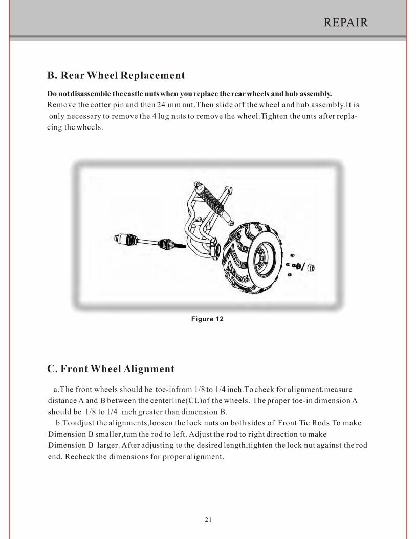
B. Rear Wheel ReplacementDo not disassemble the castle nuts when you replace the rear wheels and hub assembly.Remove the cotter pin and then 24 mm nut.Then slide off the wheel and hub assembly.It is only necessary to remove the 4 lug nuts to remove the wheel.Tighten the unts after repla-cing the wheels.
21
Figure 12
C. Front Wheel Alignment
a.The front wheels should be toe-infrom 1/8 to 1/4 inch.To check for alignment,measuredistance A and B between the centerline(CL)of the wheels. The proper toe-in dimension Ashould be 1/8 to 1/4 inch greater than dimension B. b.To adjust the alignments,loosen the lock nuts on both sides of Front Tie Rods.To makeDimension B smaller,tum the rod to left. Adjust the rod to right direction to make Dimension B larger. After adjusting to the desired length,tighten the lock nut against the rod end. Recheck the dimensions for proper alignment.

REPAIR
LOCK NUT,FR.WHEEL TIE ROD
RIGHT ROATE
LEFT ROATE
Fiqure 13
FR.WHEELTIEROD
RIGHT ROATE
LEFT ROATE
22

23
PERIODICAL CHECK AND SERVICES

WIRING DIAGRAM
24

WIRING DIAGRAM
25

TrailMaster GO-KART 300 XRX
PARTS MANUAL Version: 2 (9/19/2011)

FIG. 1 LEFT CRANKCASE COMP.
LEFT CRANKCASE COMP. REF NO. PART NO. DESCRIPTION QTY
1-1 169-4.03.111 LEFT CRANKCASE 1 1-2 169.12.104 FRONT ABSORBER BUSING SET 1 1-3 157-3.12.159 GEARBOX AIR TUBE 1 1-4 157-3.11.410 SNAP RING 1 1-5 157-3.03.615 TUBE CONNECTOR 1 1-6 157-3.12.105 REAR ABSORBER BUSHING SET 2 1-7 139.11.822 WASHER (AL) 12X20X1.5 1 1-8 152.11.306 FLANGE BOLT M12X1.5 1
1-9 157-3.11.307 TRANSMISSION HUB POSITIONING
BOLT 1
1-10 157-3.11.834 WASHER (AL) 14X22X1.3 1
1-11 157-3.10.829 TRANSMISSION HUB POSITIONING
SPRING 1
1-12 GB/T308 10 STEEL BALL SΦ10.319 1 1-13 GB/T 276 6203 BALL BEARING 6203 1 1-14 GB/T 276 6202 BALL BEARING 6202 1 1-15 157-3.11.858 WASHER (ST) 6X18X1.8 2 1-16 GB/T16674.1 FLANGE BOLT M6X12 2 1-17 169-4.10.411 INPUT SHAFT 1 1-18 GB/T 276 6205 BALL BEARING 6205 2 1-19 GB/T894.1-A 25 SNAP RING FOR SHAFT 25 1 1-20 169.12.412 OIL SEAL 25X42X7 1 1-21 157-3.10.823 IDLE PARTS 1 1-22 157-3.11.849 WASHER (AL) 10X18X1.3 1

FIG. 2
RIGHT CRANKCASE COMP.
RIGHT CRANKCASE COMP. REF NO. PART NO. DESCRIPTION QTY
2-1 169.12.104 FRONT ABSORBER BUSHING SET 1
2-2 169.03.211 RIGHT CRANKCASE 1 2-3 169.09.414 FILTER OIL TUBE 1 2-4 169.09.412 FILTER ELEMENT 1 2-5 169.09.413 FILTER SPRING 1 2-6 169.09.411 FILTER COVER 1 2-7 169.12.524 O-RING 36X3.5 1

FIG. 3
PARTS OF PISTON, BRANCE, LEFT AND RIGHT
CRANKCASE
PARTS OF PISTON, BRANCE, LEFT AND RIGHT
CRANKCASE REF NO. PART NO. DESCRIPTION QTY
3-1 169-4.01.110 BRANCE 1 3-2 169.01.311 PISTON 1 3-3 169.01.321 FIRST RING 1 3-4 169.01.322 SECOND RING 1 3-5 169.01.323 OIL RING ASSY. 1 3-6 169.01.312 PISTON PIN 1 3-7 169.01.313 PISTON PIN CIRCLIP 2 3-8 169.05.410 WATER PUMP COMP. 1 3-9 157-3.11.508 PIN 10X14 2 3-10 169.11.215 DOUBLE-SCREW LONG BOLT 4 3-11 169.12.416 OIL SEAL 30X45X5 1 3-12 169.12.522 O-RING 33.5X2.65 1 3-13 GB/T 16674.1 M6×70 BOLT M6X70 4 3-14 GB/T 16674.1 M6×100 BOLT M6X100 5
(3-15) 169.01.320 PISTON RING COMP. (3-3, 4, 5) 1 (3-16) 169.01.321 PISTON COMP. (3-2,3,4,5) 1

FIG. 4
CYLINDER HEAD COMP.
CYLINDER HEAD COMP. REF NO. PART NO. DESCRIPTION QTY
4-1 169.02.311 INTAKE VALVE 1 4-2 169.02.312 EXHAUST VALVE 1 4-3 169.02.315 LOWER VALVE SPRING SEAT 2 4-4 169.02.313 INSIDE VALVE SPRING 2 4-5 169.02.314 OUTSIDE VALVE SPRING 2 4-6 169.02.315 UPPER VALVE SPRING SEAT 2 4-7 169.02.317 VALVE LOCKING CIRCLIP 4 4-8 169.02.112 INTAKE ARM SHAFT 1 4-9 169.02.113 EXHAUST ARM SHAFT 1 4-10 169.02.120 ARM COMP. 2 4-11 169.02.210B CAM SHAFT 1 4-12 169.11.120 CAM SHAFT CLAMP 1 4-13 169.11.121 CLAMP OUTSIDE SPACER 1
4-14 169.05.712 WATER TEMPERATURE INDUCTOR 1
4-15 169.05.720 THERMOSTAT COMP. 1 4-16 169.05.730 THERMOSTAT COVER COMP. 1 4-17 152.11.407 SMALL WATER TUBE CIRCLIP 2 4-18 169.12.201 SMALL WATER TUBE 1
4-19 169.11.210 EXHAUST TUBE DOUBLE-SCREW BOLT 2
4-20 169.04.223 SMALL WATER CONNECTOR 1
4-21 169.04.210B CYLINDER HEAD MECH. COMP. 1

4-22 169.08.490 EXHAUST TUBE SEAL GASKET 1
4-23 169.11.801 OIL PRESSURE INDICATOR COPPER WASHER 1
4-24 169.12.402 VALVE STEM OIL SEAL 2 4-25 169.12.507 O-RING 9X2 1 4-26 GB/T 276 6005 BALL BEARING 1 4-27 GB/T 276 6202-RS BALL BEARING 1 4-28 GB/T 5789 M6×12 BOLT M6X12 1 4-29 GB/T 16674.1 M6×12 BOLT M6X12 2 4-30 GB/T16674.1 M6×20 BOLT M6X20 2 4-31 GB/T859 6 SPRING WASHER 2 4-32 169.02.130 ONE-WAY STOP DEVICE 1
(4-33) 169.02.200B CAM SHAFT COMP. (INCL.11,
26, 27) 1

FIG. 5
CYLINDER / TIMING CHAIN DRIVER / VALVE COVER
CYLINDER / TIMING CHAIN DRIVER / VALVE COVER REF NO. PART NO. DESCRIPTION QTY
5-1 169.02.212 TIMING DRIVEN SPROCKET 1 5-2 169.04.261 SPROCKET COVER 1 5-3 169.02.510 TIMING CHAIN 1 5-4 169.02.710 CHAIN GUIDING PLATE 1 5-5 169.02.610 TENSIONING PLATE 1 5-6 169.02.506 TENSIONING PLATE SCREW 1 5-7 169.02.410 TENSIONING DEVICE COMP. 1 5-8 169.02.221 INTAKE VALVE COVER 1 5-9 169.02.222 EXHAUST VALVE COVER 1
5-10 169.12.158 SPROCKET ROOM COVER AIR TUBE 1
5-11 169.11.411 TUBE CIRCLIP 2 5-12 169.04.261 SPROCKET ROOM COVER 1 5-13 169.11.124 BREATHER PLATE 1 5-14 169.04.312 BREATHER PIPE CONNECTOR 1 5-15 169.04.110 CYLINDER 1

5-16 169.12.319 CYLINDER HEAD SPACER COMP. 1
5-17 169.05.711 PUMP DISCHARGE ELBOW 1 5-18 169.07.210 SPARKING PLUG 1 5-19 169.11.313 COVER BOLT M8 4 5-20 157-3.11.508 PIN 10X14 2 5-21 169.11.509 PIN 14X16 2
5-22 169.11.806 SPROCKET SPACER 10X22X2.5 1
5-23 169.11.811 CYLINDER HEAD COPPER SPACER 8X18X2 4
5-24 169.12.514 O-RING 14.5X1.8 1 5-25 169.12.526 O-RING 57.5X2.3 2 5-26 169.12.527 O-RING 94X3.3 1 5-27 169.12.516 O-RING 15.5X2.5 2 5-28 169.12.306 TENSIONING DEVICE SPACER 1 5-29 169.12.304 CYLINDER PAPER SPACER 1 5-30 GB/T16674.1 M6×16 BOLT M6X16 4 5-31 GB/T16674.1 M6×20 BOLT M6X20 7 5-32 GB/T16674.1 M6×120 BOLT M6X120 2 5-33 GB/T5786 M10×1.25×25 BOLT M10X1.25X25 1
(5-34) 169.02.800 SPROCKET ROOM COVER COMP. (5-12,13,14,26) 1

FIG. 6
RIGHT COVER / MAGNETOR / ENGINE OIL PUMP /
PUMP / ELECTRIC START DRIVING
RIGHT COVER / MAGNETOR / ENGINE OIL PUMP / PUMP /
ELECTRIC START DRIVING REF NO. PART NO. DESCRIPTION QTY
6-1 169.03.411 RIGHT COVER 1 6-2 169.09.415 OIL GAUGE 1 6-3 169.03.412 PEEP DOOR SCREW PLUG 1 6-4 169.05.511 PUMP DRIVE SHAFT 1 6-5 169.05.512 PUMP GEAR 1
6-6 169.06.260 ELECTRIC START INTERMEDIATE GEAR COMP. 1
6-7 IN 169.06.310 FREE-WHEELING CLUTCH INNER RING 1
6-8 IN 169.06.310 FREE-WHEELING CLUTCH OUTER RING COMP. 1
6-9 169.06.271 INTERMEDIATE GEAR SHAFT 1 6-10 IN 169.07.110 MAGNETOR FLYING WHEEL 1 6-11 IN 169.07.110 MAGNETOR STATOR 1 6-12 169.09.110 ENGINE OIL PUMP COMP. 1

6-13 169.11.313 CRANKCASE RIGHT SIDE NUT M16X1 1
6-14 157-3.11.508 PIN 10X14 2 6-15 169.11.204 COVER PLATE 1
6-16 169.11.843 CRANKCASE RIGHT SIDE SPACER 1
6-17 169.11.859 PUMP GEAR SPACER 2
6-18 169.11.818 ELECTRIC START
INTERMEDIATE SHAFT SPACER
2
6-19 169.12.403 RIGHT COVER CAMSHAFT OIL SEAL 1
6-20 169.12.517 O-RING 18X2.65 1 6-21 169.12.513 O-RING 14X2.65 1
6-22 169.12.302 RIGHT COVER PAPER SPACER 1
6-23 169.12.311 ENGINE OIL PUMP PAPER SPACER 1
6-24 GB/T 70.1 M5×12 SCREW M5×12 2 6-25 GB/T 70.1 M5×25 SCREW M5×25 3 6-26 GB/T 70.1 M8×18 SCREW M8×18 3 6-27 GB/T70.2 M6×25 SCREW M6×25 2 6-28 GB/T16674.1 M6×16 BOLT M6×16 2 6-29 GB/T16674.1 M6×40 BOLT M6×40 10 6-30 GB/T894.1 8 SNAP RING FOR SHAFT 8 1 6-31 GB/T 894.1 12 SNAP RING FOR SHAFT 12 2 6-32 GB/T1099.1 5×5.5×16 WOODRUFF KEY 5×5.5×16 1 6-33 GB/T119 B3×22 PIN B3X22 1
(6-34) 169.03.600 RIGHT CRANKCASE COVER
COMP. (6-1,2,3,11,19,20,21,24,25)
1
(6-35) 169.05.410 PUMP COMP. (6-4,5,17,30,33) 1
(6-36) 169.06.310 FREE-WHEELING CLUTCH COMP. (6-7,8) 1
(6-37) 169.07.110 MAGNETOR COMP. (6-10,11) 1

FIG. 7
V-BELT DRIVING
V-BELT DRIVING REF NO. PART NO. DESCRIPTION QTY
7-1 169.10.110 DRIVE COMP. 1 7-2 169.10.310 V BELT 1 7-3 169.10.210 CLUTCH, DRIVEN PULLEY COMP. 1 7-4 152.03.323 HAND STARTING PART 1 7-5 157-3.11.838 WASHER 15 1 7-6 169.11.312 FLANGE BOLT M14X1 2 7-7 169.10.412 CLUTCH BRACKET BUSHING 1 7-8 139.12.520 O-RING 21X2 1

FIG. 8
GEARBOX DRIVING
GEARBOX DRIVING REF NO. PART NO. DESCRIPTION QTY
8-1 157-3.03.501 GEARBOX COVER 1 8-2 157-3.12.305 GEARBOX COVER SPACER 1 8-3 GB/T276 6302 BALL BEARING 6302 1 8-4 GB/T276 6204 BALL BEARING 6204 1 8-5 157-3.11.508 PIN Ø10×14 2 8-6 157-3.10.760 TRANSMISSION SHAFT COMP. 1 8-7 157-3.10.710 REVERSE SHAFT COMP. 1 8-8 157-3.10.610 TRANSMISSION DRUM COMP. 1 8-9 157-3.11.836 WASHER (ST)15×19×1 1 8-10 169-4.10.420 SHIFTING SHAFT COMP. 1 8-11 157-3.10.820 DECLUTCH SHIFT SHAFT 1 8-12 157-3.10.821 DECLUTCH SHIFT 1 8-13 157-3.03.612 SHORT SHAFT 2 8-14 169-4.10.450 OUTPUT GEAR SHAFT 1 8-15 GB/T5801 RNA4905 NEEDLE BEARING RNA4905 1 8-16 157-3.12.415 OIL SEAL 30×40×6 1 8-17 157-3.12.105 REAR ABSORBER BUSHING 2 8-18 GB/T276 6205 BALL BEARING 6205—2RS 1 8-19 GB/T893.1 52 SNAP RING 52 1 8-20 157-3.11.849 WASHER 25×34×1 1 8-21 GB/T894.1 25 SNAP RING 25 1 8-22 152.11.822 DRAIN PLUG M12×1.5 1 8-23 152.11.306 WASHER 12×20×1.5 1 8-24 157-3.12.404 OIL SEAL 14×28×7 1

FIG. 9
JINGLANG TYPE-RUYI LEFT COVER COMP.
(169.03.400B)
JINGLANG TYPE-RUYI LEFT COVER COMP. (169.03.400B) REF NO. PART NO. DESCRIPTION QTY
9-1 169.03.311B LEFT CRANKCASE COVER (RUYI STYLE) 1
9-2 157-3.11.508 PIN Ø10×14 2
9-3 169.12.302 LEFT CRANKCASE COVER SPACER 1
9-4 169.11.119B L. CRANK CASE COVER PLATE 2
9-5 GB/T 845 TAPPING SCREW ST3.5×8 3
9-6 169.03.315 FRONT COVER COMP. 1
9-7 GB/T818 SCREW M6×20 3
9-8 152.03.320 REAR COVER 1
9-9 GB/T 818 SCREW M5×16 2
9-10 152.03.312 NAME PLATE COVER 1
9-11 GB/T 818 SCREW M5×10 2
9-12 GB/T16674.1 FLANGE BOLT M6×40 10
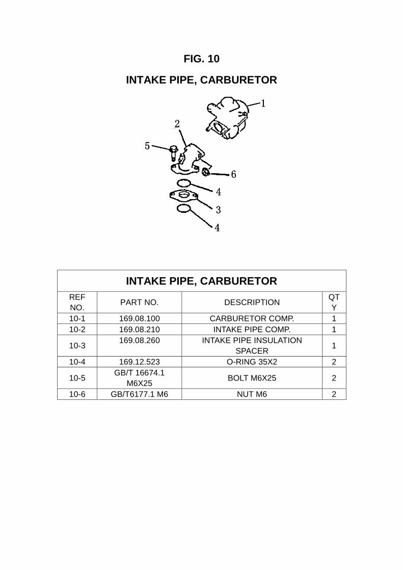
FIG. 10
INTAKE PIPE, CARBURETOR
INTAKE PIPE, CARBURETOR REF NO. PART NO. DESCRIPTION QT
Y 10-1 169.08.100 CARBURETOR COMP. 1 10-2 169.08.210 INTAKE PIPE COMP. 1
10-3 169.08.260 INTAKE PIPE INSULATION SPACER 1
10-4 169.12.523 O-RING 35X2 2
10-5 GB/T 16674.1 M6X25 BOLT M6X25 2
10-6 GB/T6177.1 M6 NUT M6 2

FIG. 11
ELECTRIC PARTS
ELECTRIC PARTS REF NO. PART NO. DESCRIPTION QTY
11-1 169.06.110 STARTOR COMP. 1 11-2 169.07.410 IGNITOR 1 11-3 169.07.310 IGNITION COIL 1 11-4 169.07.510 RECTIFIER COMP. REGULATE 1

FIG. 13
FRAME GROUP
FRAME GROUP REF NO. PART NO. DESCRIPTION QTY
13-1 6.000.061 C.B.C.CROSS BAR,(B.R.S.) 1 13-2 8.070.034-250 C.B.C.BAR CAGE(B.R.S.) 2 13-3 8.080.033 C.B.C.CROSS BAR,RR(B.R.S.) 1 13-4 8.070.035 C.B.C.BAR,L./R.SIDE(B.R.S.) 2 13-5 2.010.045 FRAME COMP.(B.R.S.) 1 13-6 7.010.049 R-WASHER 18 13-7 9.908.050N SOCKET BOLT M8*1.25*50 6 13-8 9.908.055N SOCKET BOLT M8*1.25*55 10

13-9 9.300.016 WASHER φ16 1 13-10 2.200.001 TOW BALL 1 13-11 9.400.016 LOCK WASHER φ16 1 13-12 9.101.625 BOLT M16*25 1 13-13 9.112.025 BOLT-WASHER M12*1.25*25 4 13-14 9.220.012 LOCKING FLANGE NUT M12 4 13-15 7.020.012 RUBER FOOT FLATE 2 13-16 6.000.104 HEADLIGHT UNIT 2 13-17 9.108.050 BOLT-WASHER M8*1.25*50 2 13-18 6.000.155 WINKER LIGHT ASSY.L.FR./R.RR. 2 13-19 6.000.156 WINKER LIGHT ASSY.R.FR./L.RR. 2 13-20 9.700.004 BANJO BOLT M10*24 6 13-21 6.000.089 BRAKE HOSE ASSY.L. 34" 1 13-22 6.000.090 BRAKE HOSE ASSY.R. 43" 1 13-23 6.000.230 BRAKE HOSE ASSY.RR. 80" 1 13-24 6.000.232-300G THROTTLE CABLE COMP. 1 13-25 9.106.012 BOLT M6*12 6 13-26 6.000.231-300G PARKING BRAKE CABLE COMP. 1 13-27 7.010.017 TUBE SEAT φ35 6 13-28 7.010.016 TUBE SEAT φ32 2 13-29 9.090.003 HEADLIGHT BULB 35W/35W/12V 2 13-30 7.110.034 FENDER,FR. 2 13-31 6.100.067 FRONT FENDER BRACKET,L. 1 13-32 9.100.640 BOLT M6*40 2 13-33 9.210.008 LOCKING FLANGE NUT M8 10 13-34 7.020.049 HEADLIGHT RUBBER MOUNT 4 13-35 9.106.014 BOLT-WASHER M6*14 6 13-36 6.000.135 HORN,H. 1 13-37 6.000.136 HORN,L. 1 13-38 9.100.525 BOLT M5*25 1 13-39 8.010.086 REAR MIRROR MOUNT 1 13-40 8.040.005 REAR VIEW MIRROR SPRING 1 13-41 6.000.084 REAR MIRROR ASSY. 1 13-42 6.100.102 FRONT FENDER BRACKET,R. 1 13-43 6.000.083 FOAM PADDING-1 2 13-44 6.000.116 FOAM PADDING-2 2 13-45 9.000.004-A POSITION LIGHT BULB 3W 12V 2 13-46 6.000.144 FRONT REFLECTOR 2 13-47 9.090.006 WINKER BULB 10W 12V 4 13-48 9.220.008 LOCKING FLANGE NUT M8 2 13-49 9.106.012 BOLT M6*12 2 13-50 2.100.002 SWAY BAR BRACE 3 13-51 2.100.001 SWAY BAR BRACE BUSHING 3 13-52 6.100.061 AWNING 1

13-53 7.110.030 WIND GUIDE 1 13-54 9.100.612 SCREW M6*12 8 13-55 7.120.010 RUBBER PIECE 1 13-56 9.100.640 BOLT M6*40 1 13-57 9.131.192 DECORATION PLATE I 1 13-58 9.130.192 DECORATION PLATE II 1 13-59 9.312.192 PROTECTING PLATE 1 13-60 2.041.076 BOLT M8*10 2 13-61 5.120.074 BOLT M6*20 4

FIG. 14
STEERING SHAFT ASSY.
STEERING SHAFT ASSY. REF NO. PART NO. DESCRIPTION QTY
14-1 7.010.041 STEERING BOLT COVER 1 14-2 9.100.612 SCREW M6*12 3 14-3 8.030.024 SPINDLE WHEEL 1 14-4 7.020.038 STEERING WHEEL 1 14-5 6.000.122 STEERING SHAFT 1 14-6 6.017.001 NEEDLE NK2016 2 14-7 9.700.020 SPECIAL WAHER φ20 1 14-8 9.700.120 CIRCLIP φ20 1
27

14-9 9.100.825 BOLT M8*25 2 14-10 9.400.008 LOCK WASHER φ8 2 14-11 6.000.093-250 STEERING KNUCKLE 1 14-12 4.000.014 STEERING GEAR 1 14-13 9.108.025 BOLT-WASHER M8*1.25*25 4 14-14 9.900.016 ROUND NUT M16*1.5 2 14-15 4.000.008-250 STEERING GEAR45 DEGREE ANGLE 2 14-16 9.200.010 NUT M10 2 14-17 7.020.002 BALL JIONT DUST COVER 2 14-18 8.010.157 TIE ROD 2 14-19 6.000.062 ROD END 2 14-20 9.300.010 FLAT WASHER φ10 2 14-21 9.400.010 LOCK WSAHER φ10 2 14-22 9.800.010 CASTLE NUT φ10 2 14-23 9.500.215 COTTER PIN φ2*15 2 14-24 7.020.066 STEERING KNUCKLE DUST COVER 2 14-25 8.020.014 STEERING GEAR BRACKET 2 14-26 9.220.008 LOCKING FLANGE NUT M8 8 14-27 9.708.145 THRORRLE PEDAL BOLT M8*1.25*145 1 14-28 8.040.001 THROTTLE PEDAL RETURN SPING,L. 1 14-29 9.108.040 BOLT-WASHER M8*1.25*40 2 14-30 9.200.008 NUT M8 2 14-31 4.000.016 THROTTLE PEDAL COMP. 1 14-32 9.600.515 PAN SCREW M5*15 2 14-33 9.300.005 FLAT WASHER φ5 2 14-34 9.210.005 NYLON LOCK NUT M5 2 14-35 4.000.015 BRAKE PEDAL COMP. 1 14-36 9.700.624 PIN φ6*24 1 14-37 8.010.081 SPINDLE PIN 2 14-38 9.500.212 COTTER PIN φ2*12 1 14-39 6.000.063 BRAKE LAMP SWITCH ASSY. 1 14-40 9.600.306 PAN SCREW M3*6 2 14-41 7.010.004 PEDAL BUSH 4 14-42 8.040.007 BRAKE PEDAL RETURN SPRING ,R. 1 14-43 9.708.222 BRAKE PEDAL BOLT M8*1.25*222 1 14-44 6.000.076 MASTER CYLINDER 1 14-45 9.108.035 BOLT-WASHER M8*1.25*35 2 14-46 7.020.036 THROTTLE PEDAL PAD 1 14-47 7.020.037 BRAKE PEDAL PAD 1 14-48 6.000.134 STEERING WHEEL LOCK 1 14-49 8.070.044 MASTER CYLINDER BRACKET 1 14-50 8.016.043 BOLT M6*19 2
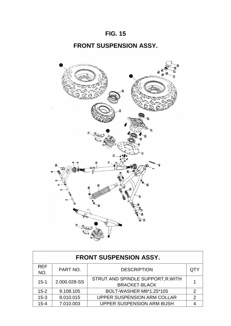
FIG. 15
FRONT SUSPENSION ASSY.
FRONT SUSPENSION ASSY. REF NO. PART NO. DESCRIPTION QTY
15-1 2.000.028-SS STRUT AND SPINDLE SUPPORT,R.WITH BRACKET-BLACK 1
15-2 9.108.105 BOLT-WASHER M8*1.25*105 2 15-3 8.010.015 UPPER SUSPENSION ARM COLLAR 2 15-4 7.010.003 UPPER SUSPENSION ARM BUSH 4

15-5 4.000.004 UPPER SUSPENSION ARM 2 15-6 9.220.008 LOCKING FLANGE NUT M8 2 15-7 9.800.012 CASTLE NUT M12 2 15-8 7.020.025 BALL HEAD DUST SEAL 4 15-9 8.020.053 BALL HEAD SPACER 4
15-10 2.000.027-SS STRUT AND SPINDLE SUPPORT,L.WITH BRACKET-BLACK 1
15-11 9.908.104 BOLT M8*14 4 15-12 8.010.014 LOWER SUSPENSION ARM COLLAR 4 15-13 9.906.012 BOLT STRAP M6*12 12 15-14 6.000.141 FR.WHEEL ASSY.,R. 20*7-8 1 15-15 7.020.016 FR.BRAKE CALIPER PAD SET 2 15-16 6.000.028 FRONT BRAKE CALIPER,L. 1 15-17 8.010.054 BRAKE DISC. 2 15-18 9.040.002 DUST SEAL 47*25-7 2 15-19 9.030.002-Z BEARING 6204-Z 2 15-20 9.710.031 CAP LUG NUT M10*1.25*31 8 15-21 8.010.085 WHEEL HUB 2 15-22 9.030.010-Z BEARIG 6202-Z 2 15-23 8.010.118 CAP LUG NUT M10 8 15-24 7.020.050 TIRE,FR.20*7-8 2 15-25 6.000.142B RIM,FR. 2 15-26 9.220.010 LOCKING FLANGE NUT M10 8 15-27 9.800.014 CASTLE NUT M14 2 15-28 9.500.220 COTTER PIN φ2*20 2 15-29 7.020.039 HUB COVER 2 15-30 9.110.040 BOLT-WASHER M10*1.25*40 4 15-31 6.000.095 FRONT BRAKE CALIPER,R. 1 15-32 6.000.325 CUSHION ASSY.,FR.L=325 2 15-33 9.110.080 BOLT-WASHER M10*1.25*80 4 15-34 8.020.034 LOWER SUSPENSION ARM DUSH CAP 8 15-35 7.010.002 LOWER SUSPENSION ARM BUSH 8 15-36 9.040.001 O-RING φ21.2*2.65 8 15-37 4.000.023 LOWER SUSPENSION ARM ASSY. 2 15-38 6.000.140B FR.WHEEL ASSY.,L. 20*7-8 1 15-39 8.010.140 ACORN M12 2 15-40 9.500.200 COTTER PIN φ3.2*26 2

FIG. 16
FULL SHIFTING ASSY.
FULL SHIFTING ASSY.
REF NO. PART NO. DESCRIPTION QTY
16-1 58330-300GK ENGINE MOUNT BRACKET I 1 16-2 58340-300GK ENGINE MOUNT BRACKET II 1 16-3 40001-300GK REVERSE CABLE FIXED PLATE 1 16-4 40002-300GK SHIFTER DISK 1 16-5 578910020125 BOLT M10x1.25x20 4 16-6 58310300k000 FRONT ENGINE MOUNT BRACKET 1 16-7 618712000125 NUT M12x1.25 3 16-8 58320300k000 BUSHING ENGINE BRACKET 1 2 16-9 578712060125 ENGINE BRACKET BOLT 2
16-10 58330300k000 BUSHING ENGINE BRACKET 2 2 16-11 58002300k000 SPACER ENGINE BRACKET 1

16-12 578710225125 ENGINE MOUNTING BOLT M10x1.25x225 1
16-13 8.010.042 WASHER-CHAIN ADJUSTER (φ12xφ35x6)
2
16-14 7.020.001 CAP WASHER-CHAIN ADJUSTER 1
16-15 8.010.045 BOTTOM CAP WASHER-CHAIN ADJUSTER
1
16-16 8.010.041 BUSHING CHAIN ADJUSTER 1 16-17 617012000125 BOLT M12x1.25 1 16-18 6.000.026-CAA CHAIN ADJUSTER ASSY. 1 16-19 618710000125 LOCKING FLANGE NUT M10x1.25 2 16-20 578510045125 BOLT M10x1.25 1 16-21 8.010.076 COLLAR ENGINE MOUNT BOLT PLATE 1 16-22 618708000125 LOCKING FLANGE NUT M 8x1.25 2 16-23 40010-300GK REVERSE CABLE 2 16-24 6.000.233-250 PARKING BRAKE ASSY. 1 16-25 9.108.020 BOLT-WASHER M8X20X1.25 2 16-26 9.300.008 WASHER 8 2 16-27 578908020125 BOLT M8 1 16-28 40700-300GK SHIFTER HOISE ASSY. 1 16-29 578906012100 NUT M6X12 2 16-30 58001-300GK ENGINE FIXED PLATE. RR 1

FIG. 17
REAR CARGO RACK / SEAT / BELT
REAR CARGO RACK / SEAT / BELT REF NO. PART NO. DESCRIPTION QTY
17-1 9.090.005 TAIL LIGHT BULB 21W/5W 12V 2 17-2 6.000.144 TAIL LIGHT 2 17-3 9.210.006 LOCK NYLON NUT M6 4 17-4 2.100.046-250 REAR CARGO RACK (B.R.S.) 1 17-5 6.000.111 REAR SIDE REFLECTOR 4 17-6 8.010.171 LUG NUT 2 17-7 7.020.032 TUBE COVER 2 17-8 6.000.241 LICENSE LIGHT ASSY. 2 17-9 9.804.003 SCREW ST3.5*10 4
17-10 9.220.008 LOCKING FLANGE NUT M8 6 17-11 6.000.145 FUEL TANK CAP COMP. 1

17-12 4.000.029 FUEL TANK COMP.(B.R.S.) 1 17-13 9.108.025 BOLT-WASHER M8*1.25*25 4 17-14 8.010.034 TANK COMP. COLLAR 4 17-15 7.020.005 RUBBER MOUNT 4 17-16 9.300.008 FLAT WASHER φ8 4 17-17 6.000.046-250 FUEL AUTO COCK ASSY.NO/OFF VALVE 1 17-18 6.000.056 GAS FILTER 1 17-19 7.020.030 TUBE COMP.FUEL #1 1 17-20 7.020.029 TUBE COMP.FUEL #2 1 17-21 7.020.031 TUBE COMP.VACUUM 1 17-22 6.000.146 SAFETY BELT 1 17-23 6.000.262 HEAD-REST 2 17-24 6.000.264 SEAT COMP.L. 1 17-25 9.700.001 SPECIAL BOLT M7/16"*28 1 17-26 9.700.002 BELT WASHER φ12 1 17-27 9.700.003 NUT BELT M7/A6" 1 17-28 9.900.840 BOLT STRAP M8*1.25*40 2 17-29 9.910.841 BOLT M8*1.25*45 2 17-30 6.000.057 SEAT RAIL SET 1 17-31 8.040.008 VACUUM TUBE 2 17-32 8.040.009 FUEL TUBE 4 17-33 6.000.263 SEAT COMP.R. 1 17-34 8.010.047 R-WASHER 4 17-35 9.908.055 BOLT M8*1.25*55 2 17-36 9.100.612 SCREW 6*12 2 17-37 7.110.002 TOOL KIT 1 17-38 7.110.003 TOOLS 1 17-39 4.000.037 AUXILIARY SPERKER 1 17-40 9.032.074 BOLT M6*20 6 17-41 9.300.005 FLAT WASHER φ5 6 17-42 9.200.006 NUT M6 6 17-43 4.000.036 MAIN SPEAKER 1

FIG. 18
AIR CLEANER/RADIAROR/BATTERY/MUFFLER ASSY.
AIR CLEANER/RADIAROR/BATTERY/MUFFLER ASSY. REF NO. PART NO. DESCRIPTION QTY
18-9 49000-300G AIR CLEANER ASSY. 1 18-10 7.090.042 TUBE COMP.WATER 1# 1 18-11 7.190.043 TUBE COMP.WATER 2# 1 18-12 7.090.044 TUBE CLAMP 10 18-13 7.090.045 TUBE COMP.WATER 3# 1 18-14 7.090.046 TUBE COMP.WATER 4# 1
34

18-15 9.100.830 BOLT M8*30*1.25 2 18-16 7.090.047 RADIATOR COMP.COLLAR 2 18-17 7.020.069 RUBBER MOUNT 6 18-18 9.200.008 NUT M8 6 18-19 6.000.248 COLLANT TANK 1 18-20 7.010.028 BATTERY COVER 1 18-21 6.000.085 BATTERY (YTX12-BS) 1 18-22 7.021.023 BATTERY BAND 1 18-23 7.020.020 BATTERY LOWER 1 18-24 57100-300G MUFFLER COMP.EX. 1 18-25 9.040.027 MUFFLER JOINT NUT M6 2 18-26 7.090.050 EX.PIPE GASKET 1 18-27 9.110.030 BOLT-WASHER M10*1.25*30 1 18-28 9.020.010 NUT M10 1 18-29 14210-300G RADIATOR COMP. 1 18-30 7.090.051 TUBE CLAMP 2 18-31 9.200.006 NUT M6 2 18-32 6.100.249-300G FAN COMP. 2 18-33 7.090.052 BOLT M6*10 6 18-34 10000-300G 300cc ENGINE 1 18-35 7.090.053 TUBE COMP WATER 5# 1 18-36 7.090.054 TUBE COMP WATER 6# 1 18-37 7.090.055 TUBE COMP WATER 7# 1 18-38 7.090.056 TUBE COMP WATER 1# 1 18-39 7.090.057 TUBE COMP WATER 2# 1 18-40 4.000.034 RADIATOR.COMP 1 18-41 9.100.625 BOLT M6*25 4 18-42 6.100.162-300G BOOT.SIDE CASE 2 18-43 8.120.055-300G CLAMP.BOOT 2 18-49 7.190.009 HEAT SENSITIVE SWICH 1 18-50 6.100.249N FAN COMP2 1 18-51 4.000.033N RADIATOR COMP COVER 1 18-52 6.000.248N COLLANT TANK CAP 1 18-53 7.090.058 RUBBER STOPPER 4
(18-54) 8.020.166-250 250CC MUFFLER CLAMP 1 18-55 9.010.098 WATER TEMPERATURE INDUCTOR 1

FIG. 19
REAR SUSPENSION ASSY.
REAR SUSPENSION ASSY. REF NO. PART NO. DESCRIPTION QTY
19-1 7.020.039 RR.HUB COVER 2 19-2 9.500.430 COTTER PIN φ4*30 2 19-3 9.800.018 CASTLE NUT M18 2 19-4 8.010.118 LUG NUT CAP M10 8 19-5 6.000.143B RIM RR. 2 19-6 8.010.169 REAR WHEEL HUB 2

19-7 9.710.031 TIRE BOLT M10*1.25*31 8 19-8 9.030.007 BEARING 6007 4 19-9 8.010.170 COLLAR 2
19-10 9.112.055 BOLT-WASHER M12*1.25*55 2 19-11 9.220.012 LOCKING FLANGE NUT M12 4 19-12 9.112.050 BOLT-WASHER M12*1.25*50 2 19-13 7.020.008 SWING ARM CUSHION BUSH 4 19-14 6.000.242 BALANCE LEVER LINK ROD 2 19-15 9.220.010 LOCKING FLANGE NUT M10*1.25 2 19-16 6.000.243 BALANCE LEVER 1 19-17 9.108.020 BOLT-WASHER M8*20*1.25 4 19-18 8.010.053-SS RR.BRAKE DISC. 1 19-19 8.030.036 BRAKE DISC.W/SPEEDO MAGNET HOLE 1 19-20 9.101.018 BOLT M10*1.5*18 1 19-21 7.020.022-250 RR.BRAKE PAD SET 1 19-22 6.000.229-250-300G CALIPER HYDRAULICAL BRAKE, RR. 1 19-23 9.908.014 ALLEN HEAD BOLE M8*1.25*16 2 19-24 6.000.244-C CV/SHAFT JOINT 2 19-25 6.000.245 CUSHION ASSY., RR. L=480 2 19-26 6.000.247 SWING ARM COMP. R. 1 19-27 6.000.246 SWING ARM COMP.L. 1 19-28 9.040.011 DUST SEAL φ62*44*10 2 19-29 6.000.148B REAR WHEEL ASSY.,R. 1 19-30 6.000.147B REAR WHEEL ASSY.,L. 1 19-31 7.020.052 TIRE ,RR.22*10-10 1 19-32 9.906.016 BOLT-WASHER M6*16 6 19-33 7.010.064 FENDER, RR. 2 19-34 6.100.068 REAR FENDER BRACKET ,R. 1 19-35 6.100.101 REAR FENDER BRACKET ,L. 1 19-36 9.105.045 BOLT-WASHER M8*1.25*45 2 19-37 9.170.002 CHAIN O-RING DRIVE 1 19-38 8.130.033 HOUSING COMP.PP AXLE BRG 2 19-39 9.030.011 BEARING E6007 2 19-40 8.110.057-300G AXLE 1 19-41 8.110.077 REAR SPROCKET 1 19-42 9.112.030 BOLT-WASHER 4 19-43 9.112.027 BOLT-WASHER 4 19-44 7.190.010 PROTECTOR,DISK 1 19-45 7.190.011 BRACKET 1 19-46 7.190.012 SENSOR 1 19-47 7.190.013 AWICO 1 19-48 9.103.005 SCREW M3*5 1 19-49 7.190.014 CIRCLIP1 1 19-50 7.190.015 RUBBER BUSH1 1

19-51 7.190.016 RUBBER BUSH2 1 19-52 7.190.017 CIRCLIP2 1 19-53 7.190.018 TIRE NIPPLE 2 19-54 7.190.019 REAR AXLE CIRCLIP 2 19-55 7.120.081 SCREN M3*6 2 19-56 7.145.076 BOLT M6*16 2 19-57 8.020.410 BRACKET 1 19-58 9.220.006 LOCKING FLANGE NUT M6 2

FIG. 20
WIRE HARNESS / ELECTRIC PARTS
WIRE HARNESS / ELECTRIC PARTS REF NO. PART NO. DESCRIPTION QTY
20-1 9.100.630 BOLT M6*30 2 20-2 9.200.006 NUT M6 2 20-3 6.000.250 REGULATE RECTIFIER COMP. 1 20-4 9.600.615 PAN SCREW M6*15 4 20-5 9.300.006 WASHER φ6 4 20-6 9.210.005 LOCKING NYLON NUT M5 2 20-7 7.110.038 SWITCH PANEL COVER 1 20-8 7.010.061 BOLT COVER 4 20-9 6.000.079 HORN SWITCH 1

20-10 7.020.051 POWER OUTLET COVER 1 20-11 6.000.087 POWER OUTLET 1 20-12 6.000.113 WINKER SWITCH UNIT 1 20-13 6.000.160 DIMMER SWITCH UNIT 1 20-14 6.000.159 ENGINE STOP BUTTON 1 20-15 6.000.158 IGNITION START SWITCH 1 20-16 6.000.153 RELAY COMP.AUDIBLE PILOT&WINKER 1 20-17 6.000.251 TEMPERATURE BUZZER 1 20-18 6.000.252 HORN RECTIFIER 1 20-19 6.100.253 SOCKET COMP. 1 20-20 9.600.655 PAN SCREW M6*55 2 20-21 6.100.254 WIRE HARNESS 2 20-22 7.010.029 ELECTRIC ASSY.COVER 1 20-23 80018-300K C.D.I.UNIT COMP. 1 20-24 6.000.256 STARTING RELAY 1 20-25 80016-300K IGNITION COIL COMP. 1 20-26 9.210.006 LOCK NYLON NUT M6 1 20-27 9.600.525 PAN SCREW M5*25 1 20-28 6.000.038 RESISTOR COMP.10W 10 1 20-29 9.600.410 PAN SCREW M4*10 1 20-30 9.210.004 LOCK NYLON NUT M4 1 20-31 4.000.038-250 SPEEDOMETER WITH HI/LO 1

FIG. 21
WARNING STICKERS
WARNING STICKERS REF NO. PART NO. DESCRIPTION QTY
21-1 9.090.007 LABEL. PARKING BRAKE 1 21-2 9.090.008 LABEL.REVERSE LEVER 1 21-3 9.090.023 LABEL.GEAR CASE 1 21-4 9.090.010 LABEL.NO LONG HAIR 1 21-5 9.090.011 LABEL.WARNING 1 21-6 9.090.012 LABEL.NO CLIMBING 1 21-7 9.090.013 LABEL.WARNING 1 21-8 9.090.014 LABEL.SEAT BELT 1 21-9 9.090.024 LABEL.RADIATOR 1
21-10 9.090.017 LABEL.WARNING 1