traffic systems and signing tr 2206 issue a july 2001 · tr 2206a specification for road traffic...
TRANSCRIPT

Traffic Systems and Signing
© Crown Copyright 2001
Applications to reproduce this material should be made to The Controller of Her Majesty's Stationery Office
First published 2000
Printed and published by the Highways Agency
TR 2206 Issue A July 2001

(This page is intentionally left blank.)

TR 2206A Specification for Road Traffic Signals Registration of Amendments
July 2001 i
REGISTRATION OF AMENDMENTS
Amend No
Page No Signature & Date of Incorporation of Amendments
Amend No
Page No Signature & Date of Incorporation of Amendments

TR 2206A Specification for Road Traffic Signals Registration of Amendments
July 2001 ii
(This page is intentionally left blank.)
TR 2206A Specification for Road Traffic Signals Table of Contents
July 2001 iii
TR 2206A SPECIFICATION FOR ROAD TRAFFIC SIGNALS Contents Chapter 1 Introduction
2 Regulations
3 Functional Requirements
4 Interfaces
5 Safety and Reliability
6 Environmental and EMC Performance
7 Optical Requirements
8 Electrical Characteristics
9 Pedestrian Push-Button Boxes
10 Miscellaneous
11 Glossary
12 References
13 History
Appendix A Tests Declarations And Requirements
Appendix B Reference Drawings
Appendix C Diagrams And Symbols
Appendix D Cable Details
Appendix E Posts

TR 2206A Specification for Road Traffic Signals Table of Contents
July 2001 iv
(This page is intentionally left blank.)

TR 2206A Specification for Road Traffic Signals Chapter 1Introduction
July 2001 1/1
1 INTRODUCTION1.1 This new specification supersedes BS 505 and TR0102, which are withdrawn.
1.2 This specification shall be used in conjunction with BS EN 12368 and BS 7987 (HD 638). It specifies the required classes and performance criteria detailed in BS EN 12368 for 200mm traffic signals for use within the United Kingdom (UK). For ease of reference traffic signals shall be referred to as signals throughout this specification.
1.3 Although BS EN 12368 makes specific reference to permanent and temporary signals; the requirements of this specification shall also apply to portable and Haul route signals at road works, and any other application that uses 200mm signals.
1.4 The UK also uses 300mm signals, which are to be phased out (see 1.15). This specification includes the optical requirements for the 300mm signals and other non-optical national requirements not defined in BS EN 12368.
1.5 The Traffic Signs Regulations and General Directions (TSRGD) provides the UK legislation for the conveying of instructions to the road user by use of signals.
1.6 The TSRGD also specifies the requirement for Statutory Type Approval for traffic control equipment. For ease of reference this will be referred to as Approval throughout this specification. Signals compliant with BS EN 12368 will not require approval.
1.7 The Highways Agency has produced TA 84/01, which is a Code of Practice aimed at designers of traffic control schemes. The main aim being to promote safety and consistency through good design practice. It is strongly recommended all scheme designers use this Code of Practice.
Scope
1.8 This specification applies to signals with 200mm roundels and to existing approved signals with 300mm roundels that are modified or changed as part of ongoing maintenance.
1.9 In conjunction with BS EN 12368 and BS 7987 it defines the requirements for the visual, structural, environmental performance and testing of signal heads (and poles) for pedestrian and vehicular road traffic use.
1.10 This specification also contains the requirements for pedestrian push-button boxes prior to the implementation of the Nearside Signal and Demand Unit (defined in TR2181), the requirements for poles, symbols, and cable core colours.
Definitions
1.11 The optical definitions and units used in this specification are from the International Lighting vocabulary CIE17.4.
Implementation
1.12 This specification will be immediately implemented from the date of issue. All new Approvals will be conducted against this specification. However signals compliant with the UK classes in BS EN 12368 will not require approval.
1.13 Approvals issued against BS505 and TR0102 will remain valid. Retrospective action against BS505 and TR0102 Approvals will not be mandatory.
1.14 From the date of issue of this specification pedestrian push-button boxes that meet Chapter 9 Pedestrian Push-Button Boxes are to be specified for new installations.
300mm Signals
1.15 The programme for phasing out 300mm signals is:
i) From the date of issue of this specification no Approval for new 300mm signals will be issued.
ii) From 1 January 2002 no 300mm roundels shall form part of a new signal controlled junction.
iii) Manufacturers may continue to provide 300mm roundels for spares and maintenance purposes.
iv) Modifications or changes to the design of existing approved signal heads containing 300mm roundels shall be submitted in accordance with TRG0500.

TR 2206A Specification for Road Traffic Signals Chapter 2Regulations
July 2001 2/1
2 REGULATIONS2.1 The product shall comply with all relevant statutes in force at the time of supply, and particular attention is drawn to those implementing European Directives.
2.2 Any requirement of the specification for goods or materials must be made in accordance with the general introduction and clauses 104 and 105 of Volume 1 of the Specification for Highways Works.
Approval
2.3 Equipment manufactured to this Standard will require to be Statutory Type Approved (hereafter referred to as Approval) before it may be operated on public roads within the United Kingdom.
Procedures for Statutory Type Approval
2.4 Details of the Approval procedure may be found in Highways Agency standard TRG 0500.
2.5 TRG 0500 details the relationship between the UK Approval and EC Standards Certification.
2.6 Any anomalies or interpretation of requirements of this standard must be resolved with the Approval Authority.
Applications for Approval
2.6 Applications for Approval of equipment or any queries regarding such Approval should be addressed to:
Traffic Systems and Signing Division Highways Agency Temple Quay House 2, The Square Temple Quay Bristol BS1 6HA England
Authorisation
2.7 In the UK, apart from Northern Ireland, any symbols to be displayed on a signal or sign that are not prescribed in the TSR&GD must be authorised by the Department for Transport, Local Government and the Regions (DTLR). In Northern Ireland a similar function is performed by the Department for Regional Development.
TR 2206A Specification for Road Traffic Signals Chapter 3Functional Requirements
July 2001 3/1
3 FUNCTIONAL REQUIREMENTSSignal Head
3.1 External wiring to the signal head shall be suitably protected to meet the requirements of BS 7671.
3.2 The backing board shall meet the minimum dimensions from BS EN 12368, class 1 or class 3. The size of the backing board is to be declared. Backing boards are to be provided with overhead signals. When an acceptable black background can be provided as part of the gantry structure separate backing boards need not be provided.
3.3 The backing board shall have a white border not less than 45 mm or more than 55 mm wide. Class 1 backing boards are not required to have a border.
3.4 All parts of the signal head assembly shall be finished matt black with the white border of the backing board (when fitted) on the front face only.
3.5 All screws and fixings shall be non-corrodible and need not be matt black.
Mounting
3.6 The signal head assembly shall be suitable for the type of mounting specified. The signal head, fixing brackets and necessary parts shall be designed so that when installed, the signals shall be adjustable both on vertical and horizontal axis to meet the alignment requirements of all approach roads and pedestrian crossings to which the signals apply.
3.7 The signal shall be adjusted so that it does not obstruct the view of other signal optical units within 25° of the axis of the beam. The signal head assembly shall be locked securely after adjustment.
Adjustment
3.8 On high-speed roads, the axis of the traffic signals as defined by the manufacturer, shall be directed at a point approximately 200 m from the primary signal head and approximately 1.5 m above ground level at the centre line of the carriageway allocated to approaching traffic.
3.9 Where traffic signals are mounted above the carriageway on mast arms, gantries or suspended on catenaries, the signals shall be directed at a point approximately 1.5m above the carriageway allocated to approaching traffic between 200 m and 400 m (depending on site conditions) from the primary signal head.
3.10 In other situations, the corresponding distances from the primary signal head shall be approximately 50 m for post-mounted signals and approximately 100 m for overhead signals. These dimensions may be varied where special circumstances require otherwise.
3.11 Where signals are intended for pedestrians, cyclists and riders, the signals shall be directed towards the centre line of the part of the carriageway allocated to pedestrian, cycle or equestrian movement unless special circumstances require otherwise.
Arrangement of Optical Units
3.12 This section applies to signals at road junctions, road works, etc., and/or pedestrian crossings. Where Puffin and nearside Toucan, Equestrian signals are used they must comply with TR2181.
Signals Intended for Drivers
3.13 Each signal head shall be arranged in one of the permitted configurations shown in the TSRGD. Where prescribed traffic signs are incorporated in the signal head they shall be internally illuminated and shall comply with the requirements of BS 873. The optical unit spacing shall be in accordance with the dimensions given in the TSRGD.
Wig-Wag Signals
3.14 Each signal head shall contain three optical units arranged at the corners of an inverted triangle with two red signals at the two top corners and a yellow signal located at the bottom. The optical unit spacing shall be in accordance with the TSRGD.
Green Arrow
3.15 Where an optical unit incorporating a green arrow is used, the arrow symbol shall be as defined in the TSRGD.

TR 2206A Specification for Road Traffic Signals Chapter 3Functional Requirements
July 2001 3/2
Signals Intended for Pedestrians
3.16 Each signal head shall contain two signal optical units arranged vertically, which shall incorporate pedestrian symbols in accordance with Department of the Environment, Transport and the Regions (DETR) drawing number 4002. The upper optical unit shall illuminate a red symbol and the lower one a green symbol. The optical unit spacing shall be as defined in the TSRGD. 200mm pedestrian symbols may be used in place of 300mm symbols with Approval and site specific Authorisation.
Signals Intended for Pedestrians and Cyclists at Toucan Crossings
3.17 Each signal head shall contain three optical units arranged in accordance with DETR drawing number 4003.5, which shall incorporate pedestrian and cycle symbols. The upper optical unit shall illuminate a red pedestrian symbol and the lower optical unit green pedestrian and cycle symbols. The optical unit spacing shall be as defined in the TSRGD. 200mm pedestrian symbols may be used in place of 300mm symbols with Approval and site specific Authorisation.
Signals Intended for Equestrians
3.18 Each signal head shall contain two optical units arranged vertically, which shall incorporate equestrian symbols in accordance with DETR drawing number 4003.2. The upper optical unit shall illuminate a red symbol and the lower one a green symbol. The optical unit spacing shall be as defined in the TSRGD. 200mm equestrian symbols may be used in place of 300mm symbols with Approval and site specific Authorisation.
Height of Signal
3.19 The mounting height of all signals shall be in accordance with the TSRGD. Authorisation from DETR is required where variation outside this range is required.
Lamp and Lamp Holder
3.20 Where a tungsten halogen lamp is used as the light source it shall be of the bi-pin M32 type for compatibility purposes.
Visor
3.21 Where visors are fitted to the optical unit, unless otherwise specified, they shall be as shown in drawing MCX0402. Visors shall resist deterioration over the operating temperature range in 6.3.
3.22 Visors shall resist substantial distortion in winds of up to 145 km/h any distortion shall not be permanent.
3.23 When specified, extra long visors, visors with a cut-away side, or visors with louvers may be fitted. Extra long visors shall be self-supporting.
3.24 When visors, anti-phantom devices or protective screens are used to meet a requirement of BS EN 12368 they shall remain fitted for all tests.

TR 2206A Specification for Road Traffic Signals Chapter 4Interfaces
July 2001 4/1
4 INTERFACESInterfaces
4.1 MCH1930 is a draft Interface guide for Signal Control Equipment. It provides guidance on inter-connection requirements for equipment and conflict voltages for signal controllers.
New Technologies
4.2 The manufacturer shall consider the implications of new technology and its interfacing with existing equipment.

TR 2206A Specification for Road Traffic Signals Chapter 5Safety and Reliability
July 2001 5/1
5 SAFETY AND RELIABILITYSafety
Optical Safety
5.1 Manufacturers shall formally certify that their signals are ‘eye-safe’ to the general public when operating normally, when failed and when being maintained in accordance with the their maintenance instructions.
5.2 Where new technology is used and no British or European safety standard exists, manufacturers are to provide a risk assessment as part of the Approval submission. Where a suitable standard exists this is to be used and compliance indicated in the Approval submission (see Appendix A Tests Declarations and Requirements).
5.3 When Light Emitting Diodes (LED) are used as the light source, the equipment shall comply with the requirements of BS EN 60825: Safety of Laser products.
Traffic Safety
5.4 The signals shall comply with class AF1 of BS 7987. The controller driving the signals is required to meet class AF5 of BS 7987.
Reliability
5.5 The equipment manufactured to this specification shall have a minimum design life of 10 years with suitable maintenance without degradation.
5.6 The data contained in MIL-HDBK 217 shall be used (where applicable) for reliability prediction.

TR 2206A Specification for Road Traffic Signals Chapter 6
Environmental and EMCPerformance
July 2001 6/1
6 ENVIRONMENTAL AND EMC PERFORMANCE6.1 Environmental tests shall be carried out to meet the requirements of BS EN 12368.
6.2 The signal head shall resist distortion in wind velocities up to 145 km/h.
6.3 The signal head shall operate without deterioration over the temperature range +60 °C to -15 °C (BS EN 12368 class A).
6.4 The signal head shall meet IP34 (BS EN 12368 class I) in accordance with BS EN 60529. The optical unit shall be protected, either as part of the signal head, or separate unit. In either option the protection shall be to IP55.
6.5 The signal head shall be manufactured from suitable material to provide mechanical protection to BS EN 12368 class IR2. The impact test shall be carried out in accordance with BS EN 50102. Surface cracks are permitted providing penetration does not occur. There shall be no degradation of the IP rating of the equipment.
6.6 Pedestrian push-button boxes shall meet BS EN 60529 IP55.

TR 2206A Specification for Road Traffic Signals Chapter 7Optical Requirements
July 2001 7/1
7 OPTICAL REQUIREMENTSOptical Characteristics
7.1 The optical performance of the signal shall comply with BS EN 12368. Summaries of the class requirements for UK signal optical performance against the provisions in BS EN 12368 are indicated below. These values are to be achieved regardless of the type of light output source.
Optical Characteristic Description EN Section Number and Class
Diameter of signal 200mm +20mm –5mm 6.2
On axis intensity 400 Cd < I axis < 2500 Cd 6.3 Performance level 3 class2
Measurement type As percentage of measured axial value
6.4 Type A
Intensity Distribution Medium Wide 6.4 Table 4 Type M
Luminance Uniformity Imin/Imax ≥ 1:10 6.5
Phantom Ratio Isig/Iphant >16:1 6.6 Table 6 Class 5
Colours of signals To be within the defined colour boxes for signal only and combined signal and phantom.
6.7 Table 7
Symbols Based on 100% of axis intensity 6.8 S1
Backgrounds Either class 1 or class 3 6.9 Table 8
Table 7.1 200mm Signals

TR 2206A Specification for Road Traffic Signals Chapter 7Optical Requirements
July 2001 7/2
Optical Characteristic Description EN Section Number and Class
Diameter of signal 300mm +/-10mm 6.2
On axis intensity 100 Cd < I axis < 1100 Cd 6.3 Performance level 1 class2
Measurement type As percentage of measured axial value
6.4 Type A
Intensity Distribution Wide 6.4 Table 3 Type W
Luminance Uniformity Imin/Imax ≥ 1:10 6.5
Phantom Ratio Isig/Iphant >1:1 6.6 Table 6 Class 1
Colours of signals To be within the defined colour boxes for signal only and combined signal and phantom.
6.7 Table 7
Symbols Based on 100% of axis intensity 6.8 S1
Backgrounds Either class 1 or class 3 6.9 Table 8
Table 7.2 300mm Signals
NOTE: It is the intended policy for the DETR to phase out 300 mm signals.
Failure of Optical Components
7.2 When high reliability is achieved by the use of clusters or strings of light output devices; failure should be an issue that is dealt with by a regular maintenance strategy.
7.3 An unmasked signal shall be considered failed when the light emitting area, under failure conditions, falls below 80% of the design light emitting area; or the luminous intensity measured on axis falls below 320 candelas. Providing that the element failures are randomly distributed within the roundel.
7.4 A masked signal shall be considered failed when the light emitting area, under failure conditions, falls below 94% of the design light emitting area, providing the element failures do not significantly degrade the appearance of the symbol.
7.5 The responsibility for deciding whether a signal should remain on or switched off, prior to replacement, shall be the responsibility of the Highway Authority. Manufacturers shall provide suitable advice in the operation and maintenance provisions for the product.
Dimming
7.6 The provisions for dimming shall not apply to portable signals.
7.7 The output intensities shall be capable of an automatic reduction during the hours of darkness to between 1/4 and 1/12 of the normal intensities. The range of dimming voltages is defined in TR0141/TR2210.
Test Conditions
7.8 Measurements shall not be made until the test unit has been switched on for 30 minutes or achieved photometric stability.

TR 2206A Specification for Road Traffic Signals Chapter 8Electrical Characteristics
July 2001 8/1
8 ELECTRICAL CHARACTERISTICSNominal Supply
8.1 The nominal supply shall comply with BS7987 class A1, nominal voltage -13% to +10%. Nominal voltage within the UK is 230v ac.
Over Voltage Protection
8.2 Class D0 of BS 7987 shall be required in respect of over voltage protection.
Mains Frequency
8.3 Class F1 of BS 7987, frequency stable to within 2% of nominal frequency, shall be required. Nominal frequency within the UK is 50Hz.
Earthing
8.4 Class M1 of BS 7987 shall be required. This requires all exposed conducting components to be bonded to earth.
EMC
8.5 The equipment shall meet the requirements of BS EN 50293.

TR 2206A Specification for Road Traffic Signals Chapter 9Pedestrian Push-Button Boxes
July 2001 9/1
9 PEDESTRIAN PUSH-BUTTON BOXES9.1 The dimensions and layout of the front of pedestrian push-button boxes shall be as defined in the TSRGD, drawing number 4003.
9.2 Consideration must be given to vandal preventative measures.
9.3 A means shall be provided for securely fixing the box to the signal post.
9.4 Provision shall be made to illuminate internally the front panel bearing the legend ‘WAIT’, which shall be white on a blue background, colour 8-087 of BS 2660.
9.5 Push-button plungers and mountings shall be designed to minimise the risk of jamming by foreign objects, moisture or corrosion. The push-button shall be insulated from all electrical contacts and connections.
9.6 No voltage in excess of Extra Low Voltage, as defined in BS 7671, shall be permitted in the push-button box.

TR 2206A Specification for Road Traffic Signals Chapter 10Miscellaneous
July 2001 10/1
10 MISCELLANEOUSOptions
10.1 Manufacturers can offer the following options by any means, the particular device and its operating limits to be declared.
i) Signal failure – indicating the signal’s output has fallen below the limits set in Chapter 4 Interfaces. This facility to be offered for the red signal only or all signals.
ii) Maintenance required – indicating a fault that requires attention. However, the signal output is still above the limits set in Chapter 4 Interfaces.
iii) Other options specified by the manufacturer or Highway Authority should be discussed with the Approval Authority.

TR 2206A Specification for Road Traffic Signals Chapter 11Glossary
July 2001 11/1
11 GLOSSARYDefinitions
For the purpose of this specification the following definitions shall apply.
Portable Signals: Are defined as those signals as prescribed in the TSRGD and Specification TR0111, normally mounted on tripods, which are intended for control of traffic for relatively short periods of time.
Temporary Signals: Are defined in LTN 1/98. They are signals other than permanent and portable signals, which normally utilise signal controllers in accordance with Specification TR0141/TR2210 and full size signal heads and stop lines. Temporary signals are capable of being used in any control configuration that can be implemented by permanent signals including pedestrian stages.
Signal Head: The assembly that includes the housing, backing board, signal optical units and associated ancillary items.
Optical Unit: The device that is designed to provide the required optical light performance. This includes the reflectors, light emitting devices, lense / diffuser, symbol / mask and signal head fixing arrangements.
Signal Controlled Junction: Signals as prescribed in the TSRGD and Specification TR0141/TR2210, intended for either permanent or temporary control of traffic and pedestrian movements.
Visor: A device located above the front of an optical unit to reduce phantom effect or restrict the field of view.
Light output device: A component(s) that emits visible light.
Other Definitions
Other definitions used in this specification can be found by reference to BS EN 12368, CIE17.4 and BS 7987.

TR 2206A Specification for Road Traffic Signals Chapter 12References
July 2001 12/1
12 REFERENCES 12.1 This specification incorporates by dated or undated reference, provisions from other publications. These normative references are cited at appropriate places in the text and the publications listed hereafter. For dated references, subsequent amendments to, or revisions of, any of these publications apply to this standard only when incorporated in it by amendment or revision. For undated references the latest edition of the publication referred to apply.
British Standards
12.2 British Standards are published by the British Standards Institution, London.
Contact: +44 (0) 1344 404 429 BS 2569 Part 1 Protection of Iron and Steel by Aluminium and Zinc Against Atmospheric Corrosion
(Withdrawn)
BS 2660 Colours for Building and Decorative Paints (Withdrawn)
BS 505 Specification for Road Traffic Signals
BS 729 Specification for Hot Dip Galvanized Coatings on Iron and Steel Articles
BS 7671 IEE Wiring Regulations
BS 7987 (HD638) Road Traffic Signal Systems
BS 873 Road Traffic Signs and Internally Illuminated Bollards
BS EN 12368 Traffic Control Equipment - Signal Heads
BS EN 50102 Degrees of Protection Provided by Enclosures for Electrical Equipment Against External Mechanical Impacts (IK Code)
BS EN 50293 EMC
BS EN 60529 Degrees of Protection Provided by Enclosures
BS EN 60825 Safety of Laser Products
Specifications
12.3 Specifications are published by the Highways Agency.
Contact: +44 (0) 117 372 8300
TR2181 Specification for Nearside Signal and Demand Unit
TR0141 Microprocessor Based Traffic Signal Controllers
TR2210 Traffic Signal Controllers
TR2203 Wig-Wag Control Systems
TRG0500 Statutory Approval of equipment for the control of Vehicular and Pedestrian Traffic on Roads
TR0102 DTP Standard Traffic Signals
MCH1930 Traffic Signal Control Equipment Interface Standard

TR 2206A Specification for Road Traffic Signals Chapter 12References
July 2001 12/2
Other Publications CIE17.4 International Lighting Vocabulary
TSRGD Traffic Signs Regulations and General Directions
ZPP Zebra, Pelican & Puffin Regulations and General Directions
LTN 1/98 The Installation of Traffic Signals and Associated Equipment
Volume 1 Specification for Highways Works
MIL HDBK 217 Reliability Prediction of Electronic Equipment
TA84/01 Code of Practice for Traffic Control and Information Systems for All Purpose Roads
Note that additional information, e.g. Local Transport Notes, Codes of Practice, relating to the siting, mounting, adjustment, commissioning and maintenance of signals are available from HMSO, DETR and the HA.
Highways Agency Drawing References
The drawings listed below are available from The Highways Agency at the address given at clause 1.1.8.
Copies, for information only, are included in this specification at Annex B.
MCX 0396 200mm Green and Yellow Cycle Symbol
MCX 0397 3 Aspect Head, Typical Assembly
MCX 0398 Pedestrian Head, Typical Assembly
MCX 0399 Legends for 300mm Green Arrow and Pedestrian Signals
MCX 0400 General Mounting of Multiple Signals
MCX 0401 Post mounted Extension Bracket
MCX 0402 Visors
MCX 0403 Post Cap Cable Termination Assembly, Typical
MCX 0404 Wig Wag General Arrangement
MCX 0476 Pedestrian Control Panel for Traffic Signals
DETR Drawing References
Relevant DETR drawings are listed below. All enquiries should be addressed to:
DTLR Traffic Management and Tolls Division Great Minster House 76, Marsham Street London SW1P 4DR.
P 3014 Wig Wag Signal General Arrangement
P 4002 Signals for Pedestrians
P 4003 Pedestrian Control Panel
P 4006 Pedestrian Signals at level Crossings
TR 2206A Specification for Road Traffic Signals Chapter 13History
July 2001 13/1
13 HISTORY Approval of this document for publication is given by the undersigned:
Issue A July 2001
Traffic Control Systems & Lighting Zone 2/16E Temple Quay House 2 The Square Temple Quay Bristol BS1 6HA M.J. SMITH
Team Manager Traffic Control Systems & Lighting

TR 2206A Specification for Road Traffic Signals APPENDIX A
July 2001 A/1
APPENDIX A TESTS DECLARATIONS AND REQUIREMENTS Tests, Declarations and Requirements (Informative)
A1 This specification consists of normative and informative text. The table below indicates which clauses are applicable to approval and the method by which they are to be met.
Paragraph Brief Description Test or Declare
3.2 & 3.3 Backing boards Declare
3.6 Mounting and adjustment Declare
3.13 Arrangement of optical units Declare
3.20 Lamp (only applicable to Tungsten Halogen)
Declare
3.21 & 3.22 Visors Declare
4.1 Interfaces Declare
7.1 Optical characteristics Test
7.3 & 7.4 Failure Declare
7.6 & 7.7 Dimming Declare
8.1, 8.2, 8.3, & 8.4 Electrical characteristics Declare
8.5 EMC Test
9.1, 9.2, 9.3, 9.4, 9.5, & 9.6 Push-button boxes Declare
6.1 Environmental testing Test
Chapter 6 Environmental and EMC Performance
Environmental suitability Declare
6.4 IP rating Test
6.5 Impact resistance Test
5.1, 5.2, 5.3, & 5.4 Safety Declare
10.1 Options Declare
NOTE:
i) BS EN 12368 Annex A provides additional information.
ii) The statement of compliance shall be supported by a technical construction file, which details how the requirements above are met.

TR 2206A Specification for Road Traffic Signals APPENDIX B
July 2001 B/1
APPENDIX B REFERENCE DRAWINGS B1 The following MCX drawings are provided for Information purposes only
MCX 0396 Traffic Signal 200mm Green and Yellow Cycle Symbol
MCX 0397 Traffic Signal 3 Aspect Head Typical Assembly
MCX 0398 Traffic Signal Pedestrian Head Typical Assembly
MCX 0399 Traffic Signal Legends for 300mm Green Arrow and Pedestrian Lights Signals
MCX 0400 Traffic Signal General Mounting of Multiple Signals (sheets 1, 2 & 3)
MCX 0401 Traffic Signal Extension Bracket
MCX 0402 Traffic Signal Visors (sheets 1 & 2)
MCX 0403 Traffic Signal Post Cap Cable Termination assembly
MCX 0404 Traffic Signal Wig Wag General Arrangement
MCX 0476 Pedestrian Control Panel for Traffic Signals (sheets 1 &2)
Drawings only available on Microfiche – therefore not included in the electronic version of this document.
TR 2206A Specification for Road Traffic Signals APPENDIX C
July 2001 C/1
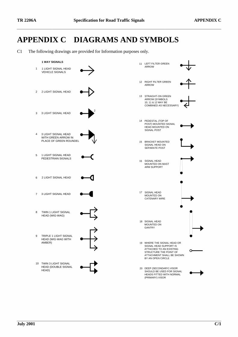
APPENDIX C DIAGRAMS AND SYMBOLS C1 The following drawings are provided for Information purposes only.
1
1 WAY SIGNALS
1 LIGHT SIGNAL HEADVEHICLE SIGNALS
2 2 LIGHT SIGNAL HEAD
3 3 LIGHT SIGNAL HEAD2
4 3 LIGHT SIGNAL HEADWITH GREEN ARROW INPLACE OF GREEN ROUNDEL
5 1 LIGHT SIGNAL HEADPEDESTRIAN SIGNALS
6 2 LIGHT SIGNAL HEAD
7 3 LIGHT SIGNAL HEAD
8 TWIN 1 LIGHT SIGNALHEAD (WIG-WAG)
9 TRIPLE 1 LIGHT SIGNALHEAD (WIG-WAG WITH AMBER)
10 TWIN 3 LIGHT SIGNALHEAD (DOUBLE SIGNALHEAD)
11 LEFT FILTER GREENARROW
12 RIGHT FILTER GREENARROW
13 STRAIGHT-ON GREEN ARROW (SYMBOLS10, 11 & 12 MAY BECOMBINED AS NECESSARY)
14 PEDESTAL (TOP OF POST) MOUNTED SIGNALHEAD MOUNTED ONSIGNAL POST
15 BRACKET MOUNTEDSIGNAL HEAD ONSEPARATE POST
16 SIGNAL HEADMOUNTED ON MASTARM SUPPORT
17 SIGNAL HEADMOUNTED ON CATENARY WIRE
18 SIGNAL HEADMOUNTED ON GANTRY
20 DEEP (SECONDARY) VISORSHOULD BE USED FOR SIGNALHEADS FITTED WITH NORMAL(PRIMARY) VISOR
WHERE THE SIGNAL HEAD ORSIGNAL HEAD SUPPORT ISATTACHED TO AN EXISTINGSTRUCTURE THE POINT OFATTACHMENT SHALL BE SHOWNBY AN OPEN CIRCLE
19

TR 2206A Specification for Road Traffic Signals APPENDIX C
July 2001 C/2
21
2 WAY SIGNALS
ANY COMBINATION OFSIGNALS 1-21 MAY BEUSED
22
3 WAY SIGNALS
ANY COMBINATION OFSIGNALS 1-21 MAY BEUSED
23
DETECTORS
MOVEMENT DETECTORSSENSITVE TO VEHICLESIN 1 DIRECTION (ARROWINDICATES DIRECTION INWHICH DETECTOR ISSENSITIVE)
Calls 3 and 4Extends 4
24 MOVEMENT DETECTORSSENSITVE TO VEHICLESIN BOTH DIRECTIONS
25 PRESENCE DETECTORFOR SYMBOLS 23 & 24THE LINE SHOULD ENCLOSETHE AREA OF DETECTION
P
26
PEDESTRIAN PUSH BUTTONS
PEDESTRIAN SINGLE PUSH BUTTON WITH ILLUMINATED'WAIT' INDICATION
27 PEDESTRIAN DOUBLE PUSH BUTTON WITH ILLUMINATED'WAIT' INDICATION
TR
28 TRAFFIC SIGNS ASSOCIATEDWITH TRAFFIC SIGNALS. SIGNSSHALL BE SHOWN WITH THEAPPROPRIATE LETTERS INTHE BOX AS FOLLOWS:TL TURN LEFTTR TURN RIGHTAO AHEAD ONLYNLT NO LEFT TURNNRT NO RIGHT TURNNUT NO 'U' TURN
NOTE TL AND NLT NORMALLY FITTEDON LEFT OF SIGNALS, TR AND NRTON RIGHT
TRAFFIC SIGNS ASSOCIATEDWITH TRAFFIC SIGNALS
29 CONTROLLER OR OTHEREQUIPMENT HOUSING
30 SIGNAL DIMMING SENSOR PE
31 Vehicular traffic approach detector
32 Vehicular traffic stop line detector
33 Guard railing
34 Pedestrian on-crossing detector
35 Pedestrian kerbside detector
*
36 Traffic signal offset or bracket mounted
37 Pedestrian nearside signal
40 Tactile paving
38 Pedestrian demand unit
39 Surface mounted pedestrian Kerbside detector

TR 2206A Specification for Road Traffic Signals APPENDIX C
July 2001 C/2
Call 3 & 5Extend 5
Call 2Extend 2
Call 1 & 2Extend 1 Extend 1 Extend 5
Extend 2Call 4
Call 4
Extend 1
Extend 3
Extend 2
NOTE: A CALL FOR STAGE 4 WILL SUPPRESSA CALL FOR STAGE 3
1
2
3 4
5
N
PHASING DIAGRAM
1 2 5
3
4
STAGE DIAGRAM
NOTE: STAGES ARE NORMALLY SERVEDCLOCKWISE. ARROWS INDICATE WHERE ONESTAGE IS AUTOMATICALLY FOLLOWED BY ANOTHERSTAGE, ie THE SUBSEQUENT STAGE CANNOT BEOMITTED

TR 2206A Specification for Road Traffic Signals APPENDIX D
July 2001 D/1
APPENDIX D CABLE DETAILS
R E D Y E LLO WG R E E NB L A C KB L U EW H IT EO R A N G EB R O W NP U R P LEG R E YR E D / W H IT ER E D / B LU ER E D / B LA C KR E D / Y E LLO WR E D / G R E YR E D / B R O W NR E D / P U R P LER E D / G R E E NR E D / O R A N G EW H IT E / B LU E
oro ro r
o rR E D orB LA C K or
R E D 4A M B E R 4
R E D G R E E N 4B LU EY E LLO W R E D 5B LA C K A M B E R 5
G R E E N 5
N E U T R A LB lac k in L ow V o lta ge C a b le s is a lw ays N eu tra lA ll O the r C o lo urs m ay b e L ive
P E L IC AN
F O R E L V W IR IN G F O L L O W AS P E R P E L IC AN
P E C N E U T R A LP E C LO A DP E C L IN ER E D 2
G R E E N 1A M B E R 1
L O W V O L T AG E
R E D 1
G R E E N 2A M B E R 2
G R E E NY E LLO W
R E D
G R E E N 3 G R E E N M A NW A IT (240v)A M B E R 3R E D M A NR E D 3
B LA C K
O R A N G EP U R P LE
R E D / B LA C K
R E D / B R O W NR E D / Y E LLO W
R E D / G R E Y
R E D / W H IT EG R E Y
R E D / B LU E
B R O W N W H IT E
B LU E
JU N C T IO N
O R A N G EW H IT EG R E YP U R P L E
A G D +24VA G D 0vA G D O U T P U TA G D O v
A U D IO +A U D IO -
B R O W NB LU ER E DB LA C K
R E DO R A N G EY E LLO WG R E E NR E D / W H IT EG R E YR E D / B LU EB LA C K
R E D M A NW A IT (2 40V )
E X T R A L O W V O L T AG E
P U S H B U T T O N +P U S H B U T T O N -
R E D / B LU ER E D / W H IT E
W A IT 48vW A IT N E U T R A L
B R O W NW H IT E
P E C N E U T R A L
L O W V O L T AG E
G R E E N M A NN E U T R A LP E C L IN EP E C L O A D
A M B E RG R E E N
B LU E
C AB L E C O L O U R C O D E AN D R E C O M M E N D E D U S E AG E
M U L T I-C O R E C AB L E
1 'P R ' F E E D E R
8 CO
RE
12 C
ORE
16 C
ORE
20 C
ORE
R E D 1R E D 2
2 'P R ' F E E D E R
L O O P F E E D E R C A B L E
Y Z LO O P T A ILS
LO O P T A ILS
X L O O P T A ILS

TR 2206A Specification for Road Traffic Signals APPENDIX E
July 2001 E/1
APPENDIX E POSTSE1 Details of the post design are outline here as an informative requirement to ensure fitness for purpose. The post is not subject to Approval.
E2 The post shall be designed and constructed to provide adequate support and stability for the signal head and shall be fitted with a weather-proof cap.
E3 The height of signal posts may be increased by 150mm above the upper bracket fixing to permit better access to the post cap termination assembly (for height of signal, see the TSRGD).
E4 Where a ground plate is used, the minimum area of the ground plate shall be 0.09m2 with each side being not less than 0.3m in length.
E5 Where an aperture is required to permit the entry of an electric supply cable, unless otherwise specified by the purchaser, it shall be not less than 300 mm high by 50 mm wide and the top of the slot shall be between 75mm and 130 mm below ground level.
E6 The top and bottom of the aperture shall be radiused with radii equal to half the slot width.
E7 Where an aperture is required to permit the entry of cables, which are not supply cables, it shall be capable of accommodating four cables each of 32 mm diameter.
E8 Any apertures above ground level shall be fitted with a suitable gland or grommet maintaining as far as possible a smooth surface.
E9 Where an access door is included in the post the cable entry apertures shall be oriented in relation to the door to ensure the safety of personnel.
E10 Unless otherwise specified the post shall be of sufficient length to allow a minimum of 700 mm below ground level when correctly erected.
E11 An anti-corrosive finish effective over the operating temperature range specified in 6.3 shall protect the interior of steel posts.
E12 The exterior portion of the steel posts shall be protected:
i) by spraying with molten zinc to BS 2569, Part 1; or
ii) a finish complying with the requirements of BS 729; or
iii) other approved finishes.
E13 The colour of the exterior surface shall be grey unless otherwise requested. The TSRGD and Zebra Pelican and Puffin Regulations and General Directions (ZPP) identify other allowed colours.
E14 All plastic coatings shall, even when scratched or torn, be resistant to peeling.
E15 Any surface cut after galvanising, painting, or the application of the plastic finish shall be protected as appropriate.
E16 All non-current carrying metal parts used to support the terminal assembly (housed at the top of the post) and the bonding for cable earth leads shall be non-corrodible and earthed in accordance with the current requirements of BS7987.
E17 A method of terminating armoured cable is shown in drawing MCX0403, CET glands may also be used. The electrical earth connection between the frame supporting the terminal assembly and the metal of the signal post shall be firm and shake-proof. The terminal assembly support frame shall resist vibration fatigue when supporting its full complement of cables and terminal blocks.
E18 The post cap, covering the cable termination assembly, shall be constructed so that it will not become loose due to vibration or adverse weather conditions. The post cap shall prevent rain from reaching the termination assembly.
Supports For Overhead Mounted Signals
E19 Overhead signals may be mounted on mast arms or gantries, or on double catenaries supporting the top and bottom of the signal head or heads. The assembly shall resist permanent distortion in wind velocities up to 145 km/h and shall provide a minimum clearance of 5.5 m with the carriageway.