traffic amendment regulation (no. 4) 2011 · traffic amendment regulation (no. 4) 2011 2011 sl no....
TRANSCRIPT

Queensland
Traffic Amendment Regulation (No. 4) 2011
Subordinate Legislation 2011 No. 136
made under the
Transport Operations (Road Use Management) Act 1995
Contents
Page
1 Short title . . . . . . . . . . . . . . . . . . . . . . . . . . . . . . . . . . . . . . . . . . . 3
2 Regulation amended . . . . . . . . . . . . . . . . . . . . . . . . . . . . . . . . . . 3
3 Amendment of s 4 (Definitions) . . . . . . . . . . . . . . . . . . . . . . . . . . 3
4 Insertion of new ss 210D and 210E . . . . . . . . . . . . . . . . . . . . . . . 4
210D Operating and testing digital combined redlight and speed camera systems . . . . . . . . . . . . . . . . . . . . . . . 4
210E Operating and testing digital point-to-point camera systems . . . . . . . . . . . . . . . . . . . . . . . . . . . . . . . . . 6
5 Amendment of s 211 (Markings or writings on photographic detection device images other than ANPR camera system images) . . . . . . . . . . . . . . . . . . . . . . . . . . . . . . . . . . . . . . . . 7
6 Amendment of sch 10 (Approved photographic detection devices) . . . . . . . . . . . . . . . . . . . . . . . . . . . . . . . . . . . . . . . 8
7 Amendment of sch 11 (Data blocks) . . . . . . . . . . . . . . . . . . . . . . 9
8 Insertion of new schs 12–15. . . . . . . . . . . . . . . . . . . . . . . . . . . . . 9
Schedule 12 Data blocks for digital redlight camera systems
Schedule 13 Data blocks for digital speed camera systems
Schedule 14 Data blocks for digital combined redlight and speed camera systems
Schedule 15 Data blocks for digital point-to-point camera system—images taken by Redflex

Contents
Traffic Amendment Regulation (No. 4) 2011
point-to-point camera system models P2P101, P2P102, P2P103, P2P104, P2P105 and P2P106
Page 2 2011 SL No. 136

[s 1]
Traffic Amendment Regulation (No. 4) 2011
1 Short title
This regulation may be cited as the Traffic AmendmentRegulation (No. 4) 2011.
2 Regulation amended
This regulation amends the Traffic Regulation 1962.
3 Amendment of s 4 (Definitions)
(1) Section 4—
insert—
‘digital combined redlight and speed camera system means acamera system described in schedule 10, part 6.
digital point-to-point camera system means a camera systemdescribed in schedule 10, part 7.
Note—
A digital point-to-point camera system comprises multiple cameras. Itcan be used to provide evidence of a prescribed offence based on—
(a) an image, or images, of a vehicle taken by 1 of the system’scameras at a particular location and time; or
(b) images of a vehicle taken by more than 1 of the system’s camerasat different points on a road, the distance between which is used tocalculate the average speed of the vehicle (see the Act, section120A).’.
(2) Section 4, definition camera system hardware, ‘or digitalspeed camera system’—
omit, insert—
‘, digital speed camera system, digital combined redlight andspeed camera system or digital point-to-point camera system’.
(3) Section 4, definition camera system hardware, examples, after‘camera’—
insert—
‘or cameras’.
2011 SL No. 136 Page 3

[s 4]
Traffic Amendment Regulation (No. 4) 2011
4 Insertion of new ss 210D and 210E
After section 210C—
insert—
‘210D Operating and testing digital combined redlight and speed camera systems
‘(1) If a digital combined redlight and speed camera system isused to provide evidence of a prescribed offence, thefollowing provisions must be complied with—
(a) for a prescribed offence that is a redlight offence—
(i) the system’s camera must be aimed so that animage taken by the camera shows—
(A) the front or rear of a vehicle that is drivenpast the stop line for a traffic light or, if thereis no stop line, the traffic light; and
(B) the stop line (if any) and the traffic lightshowing a red symbol; and
(ii) a component of the system that detects vehiclesmust be installed in a way that recognises when avehicle passes a stop line or traffic light; and
(iii) the system and traffic light must be linked sothat—
(A) after the traffic light changes to red and aprogrammed delay has elapsed, a vehiclepassing the stop line or traffic light activatesthe camera; and
(B) the activated camera takes at least 2 imagesof the vehicle, stop line (if any) and trafficlight;
(b) for a prescribed offence other than a redlight offence,the system’s camera must be positioned and aimed sothat an image taken by the camera shows—
(i) if the prescribed offence is a speeding offence—thefront or rear of a vehicle the speed of which wasmeasured by the system; or
Page 4 2011 SL No. 136

[s 4]
Traffic Amendment Regulation (No. 4) 2011
(ii) otherwise—the front or rear of a vehicle in relationto which the system is used to provide evidence ofthe offence;
(c) if a relevant event happens—the system must be testedin accordance with the specifications of the system’smanufacturer to ensure the system operates correctly;
(d) if a fault is indicated in the system because of testingunder paragraph (c)—corrective action must be takenand the testing must be repeated until no fault isindicated in the system;
(e) if the tests or an image when viewed indicate a fault hasaffected the proper operation of the system as requiredunder this section, the image must be rejected forevidentiary purposes.
‘(2) Each of the following is a relevant event for subsection(1)(c)—
(a) the installation of the camera system;
(b) the reinstallation, replacement or repair of camerasystem hardware for the system;
Example—
the replacement of the system’s camera
(c) a change to the computer software used by the system;
Example—
the application of a software patch
(d) a change of the maximum speed limit for the place atwhich the system’s camera is located.
‘(3) In this section—
redlight offence means a prescribed offence against theQueensland Road Rules, section 56(1) or (2).
speeding offence means a prescribed offence against theQueensland Road Rules, section 20.
2011 SL No. 136 Page 5

[s 4]
Traffic Amendment Regulation (No. 4) 2011
‘210E Operating and testing digital point-to-point camera systems
‘(1) If a digital point-to-point camera system is used to provideevidence of a prescribed offence, the following provisionsmust be complied with—
(a) each camera in the system that takes an image or imageson which evidence of the offence is based must bepositioned and aimed so that an image taken by thecamera shows the front or rear of the vehicle in relationto which the system is used to provide evidence;
(b) if a relevant event happens—the system must be testedin accordance with the specifications of the system’smanufacturer to ensure the system operates correctly;
(c) if a fault is indicated in the system because of testingunder paragraph (b)—corrective action must be takenand the testing must be repeated until no fault isindicated in the system;
(d) if the tests or an image when viewed indicate a fault hasaffected the proper operation of the system as requiredunder this section—to the extent subsection (3) does notapply to the evidence of the offence, the image must berejected for evidentiary purposes.
‘(2) Each of the following is a relevant event for subsection(1)(b)—
(a) the installation of the camera system;
(b) the reinstallation, replacement or repair of camerasystem hardware for the system;
Example—
the replacement of one of the system’s cameras
(c) a change to the computer software used by the system;
Example—
the application of a software patch
(d) a change of the maximum speed limit for a place atwhich any of the system’s cameras are located;
Page 6 2011 SL No. 136

[s 5]
Traffic Amendment Regulation (No. 4) 2011
(e) a reconfiguration of the system’s cameras that changesthe 2 points on a road the distance between which isused for calculating the average speed of a vehicle underthe Act, section 120A.
‘(3) This section does not prevent a digital point-to-point camerasystem being used to provide evidence of a prescribed offenceif—
(a) 1 or more of the system’s cameras takes an image, orimages, on which evidence of the offence is based; and
(b) there is a fault in the system, or the system is beingtested; and
(c) the fault or testing mentioned in paragraph (b) does notaffect the proper operation of—
(i) the camera or cameras mentioned in paragraph (a);or
(ii) any part of the system associated with theoperation of the camera or cameras mentioned inparagraph (a) for the provision of evidence of theoffence.
Example for subsection (3)—
A digital point-to-point camera system consists of 2 cameras, camera Aand camera B. There is a fault in camera B that does not affect theproper operation of camera A or any part of the system associated withthe operation of camera A for the provision of evidence of a prescribedoffence. The system is not prevented from being used to provideevidence of a prescribed offence based on an image taken by cameraA.’.
5 Amendment of s 211 (Markings or writings on photographic detection device images other than ANPR camera system images)
(1) Section 211(1), paragraphs (d) and (e)—
omit, insert—
‘(d) for an image of a vehicle taken by a digital redlightcamera system—schedule 12; and
2011 SL No. 136 Page 7

[s 6]
Traffic Amendment Regulation (No. 4) 2011
(e) for an image of a vehicle taken by a digital speed camerasystem—schedule 13; and
(f) for an image of a vehicle taken by a digital combinedredlight and speed camera system—schedule 14; and
(g) for an image of a vehicle taken by a digitalpoint-to-point camera system—schedule 15.’.
(2) Section 211(2)—
insert—
‘on, an image, includes adjacent to or associated with theimage.’.
6 Amendment of sch 10 (Approved photographic detection devices)
(1) Schedule 10, part 4—
insert—
‘Redflex redlight camera system model RL101’.
(2) Schedule 10, part 5—
omit, insert—
‘Part 5 Digital speed camera system
‘Gatso speed camera system models Radar AUS GS, RS-GS2and RS-GS11
LTI speed camera system model LTI 20-20 TruCAM
Redflex speed camera system model MR101
Robot speed camera system models Multaradar CM,Multaradar SD480 and Multaradar SD580
Vitronic speed camera system model Poliscan Speed’.
(3) Schedule 10—
insert—
Page 8 2011 SL No. 136

[s 7]
Traffic Amendment Regulation (No. 4) 2011
‘Part 6 Digital combined redlight and speed camera system
‘Gatso combined redlight and speed camera system modelGTC-GS11
Redflex combined redlight and speed camera system modelsSR101, SR102, SR103, SR104, SR105 and SR106
Robot combined redlight and speed camera system modelsTraffistar SR420, Traffistar SR490, Traffistar SR520 andTraffistar SR590
‘Part 7 Digital point-to-point camera system
‘Redflex point-to-point camera system models P2P101,P2P102, P2P103, P2P104, P2P105 and P2P106’.
7 Amendment of sch 11 (Data blocks)
(1) Schedule 11, heading, after ‘blocks’—
insert—
‘for analogue redlight camera systems and analogue speedcamera systems’.
(2) Schedule 11, parts 4 and 5—
omit.
8 Insertion of new schs 12–15
After schedule 11—
insert—
2011 SL No. 136 Page 9
[s 8]
Traffic Amendment Regulation (No. 4) 2011
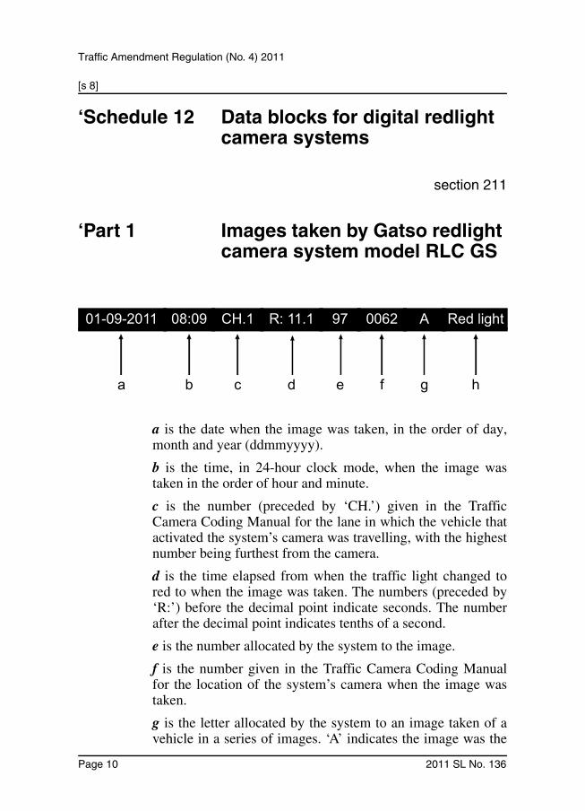
‘Schedule 12 Data blocks for digital redlight camera systems
section 211
‘Part 1 Images taken by Gatso redlight camera system model RLC GS
a is the date when the image was taken, in the order of day,month and year (ddmmyyyy).
b is the time, in 24-hour clock mode, when the image wastaken in the order of hour and minute.
c is the number (preceded by ‘CH.’) given in the TrafficCamera Coding Manual for the lane in which the vehicle thatactivated the system’s camera was travelling, with the highestnumber being furthest from the camera.
d is the time elapsed from when the traffic light changed tored to when the image was taken. The numbers (preceded by‘R:’) before the decimal point indicate seconds. The numberafter the decimal point indicates tenths of a second.
e is the number allocated by the system to the image.
f is the number given in the Traffic Camera Coding Manualfor the location of the system’s camera when the image wastaken.
g is the letter allocated by the system to an image taken of avehicle in a series of images. ‘A’ indicates the image was the
01-09-2011 08:09 CH.1 R: 11.1 97 0062 A Red light
a b c d e f g h
Page 10 2011 SL No. 136

[s 8]
Traffic Amendment Regulation (No. 4) 2011
first image taken, and ‘B’ indicates the image was the secondimage taken, in the series.
h is the camera system type and indicates the system is adigital redlight camera system.
Example—
The diagram in this part shows—
• the image was taken at 8:09a.m. on 1 September 2011
• the vehicle that activated the system’s camera was in the lane giventhe number 1 in the Traffic Camera Coding Manual
• the image was taken 11.1 seconds after the traffic light changed tored
• the image was allocated the number 97 by the system
• the system’s camera was located at the place given the number 62 inthe Traffic Camera Coding Manual
• the image was the first image taken in a series of images
• the camera system type is a digital redlight camera system.
‘Part 2 Images taken by Redflex redlight camera system model RL101
• ‘date’ followed by a sequence of numbers is the datewhen the image was taken, in the order of day, monthand year (ddmmyyyy)
• ‘direction’ followed by the word ‘Away’ or ‘Towards’ isthe direction that the vehicle in relation to which thesystem is used to provide evidence of a prescribedoffence (the target vehicle) was travelling in relation tothe system’s camera. ‘Away’ indicates the target vehiclewas travelling away from the camera and ‘Towards’indicates the target vehicle was travelling towards thecamera
2011 SL No. 136 Page 11
[s 8]
Traffic Amendment Regulation (No. 4) 2011
• ‘dist interval’ followed by a number is the distancetravelled by the target vehicle, in metres, from itslocation when an image of the vehicle was taken to itslocation when another image of the vehicle was taken
• ‘elapsed time’ followed by a number is the time elapsed,in seconds, from when an image of the target vehiclewas taken to when another image of the vehicle wastaken
• ‘image no’ followed by a number is the numberallocated by the system to the image
• ‘lane’ followed by a number is the number given in theTraffic Camera Coding Manual for the lane in which thetarget vehicle was travelling, with the highest numberbeing furthest from the camera
• ‘location’ followed by writing is the name of thelocation where the image was taken
• ‘model’ followed by writing is the model of the systemused to take the image
• ‘phase’ followed by writing is the traffic light phasewhen the image was taken (the relevant phase)
• ‘phase duration’ followed by a number is the timeelapsed, in seconds, from when the traffic light changedto the relevant phase to when the image was taken
• ‘serial no’ followed by a number or writing is the serialnumber of the system used to take the image
• ‘site code’ followed by a number is the number given inthe Traffic Camera Coding Manual for the location ofthe system’s camera when the image was taken
• ‘speed limit’ followed by a number is the maximumspeed limit, in kilometres per hour, for the place atwhich the image was taken when the image was taken
• ‘time’ followed by a sequence of numbers is the time in24-hour clock mode when the image was taken in theorder of hour, minute and second.
Page 12 2011 SL No. 136

[s 8]
Traffic Amendment Regulation (No. 4) 2011
Example—
A data block may show the following information—
• date: 01/09/2011
• direction: Away
• dist interval: 10m
• elapsed time: 0.50s
• image no: 45
• lane: 2
• location: Beaudesert Road, Calamvale
• model: RL101
• phase: red
• phase duration: 1.50s
• serial no: 2898
• site code: 2222
• speed limit: 80km/h
• time: 22:30:00.
The data block indicates the following—
• the image was taken at 10:30p.m. on 1 September 2011
• the target vehicle was travelling away from the system’s camera
• the target vehicle travelled 10 metres from its location when animage of the vehicle was taken to its location when another imageof the vehicle was taken
• the time elapsed from when an image of the target vehicle wastaken to when another image of the vehicle was taken was 0.5seconds
• the image was allocated the number 45 by the system
• the target vehicle was in the lane given the number 2 in the TrafficCamera Coding Manual
• the location where the image was taken was Beaudesert Road atCalamvale
• the model of the system used to take the image was RL101
• the traffic light was in its red phase
• the image was taken 1.5 seconds after the traffic light changed tored
2011 SL No. 136 Page 13

[s 8]
Traffic Amendment Regulation (No. 4) 2011
• the serial number of the system used to take the image was 2898
• the system’s camera was located at the place given the number 2222in the Traffic Camera Coding Manual
• the maximum speed limit at that place and time was 80km/h.
‘Schedule 13 Data blocks for digital speed camera systems
section 211
‘Part 1 Images taken by Gatso speed camera system models Radar AUS GS, RS-GS2 and RS-GS11
• ‘date’ followed by a sequence of numbers is the datewhen the image was taken, in the order of day, monthand year (ddmmyyyy)
• ‘direction’ followed by a letter ‘A’ or ‘F’ is the directionthat the vehicle the speed of which was measured by thesystem (the target vehicle) was travelling in relation tothe system’s camera. ‘A’ indicates the target vehiclewas travelling away from the camera and ‘F’ indicatesthe target vehicle was travelling towards the camera
• ‘dist interval’ followed by a number is the distancetravelled by the target vehicle, in metres, from itslocation when an image of the vehicle was taken to itslocation when another image of the vehicle was taken
• ‘elapsed time’ followed by a number is the time elapsed,in seconds, from when an image of the target vehiclewas taken to when another image of the vehicle wastaken
• ‘image no’ followed by a number is the numberallocated by the system to the image
Page 14 2011 SL No. 136

[s 8]
Traffic Amendment Regulation (No. 4) 2011
• ‘lane’ followed by a number is the number given in theTraffic Camera Coding Manual for the lane in which thetarget vehicle was travelling
• ‘location’ followed by writing is the name of thelocation where the image was taken
• ‘model’ followed by writing is the model of the systemused to take the image
• ‘serial no’ followed by a number or writing is the serialnumber of the system used to take the image
• ‘site code’ followed by a number is the number given inthe Traffic Camera Coding Manual for the location ofthe system’s camera when the image was taken
• ‘speed’ followed by a number is the speed, in kilometresper hour, of the target vehicle measured by the systemwhen the image was taken
• ‘speed limit’ followed by a number is the maximumspeed limit, in kilometres per hour, for the place atwhich the image was taken when the image was taken
• ‘time’ followed by a sequence of numbers is the time in24-hour clock mode when the image was taken in theorder of hour, minute and second.
Example—
A data block may show the following information—
• date: 01/09/2011
• direction: A
• dist interval: 10m
• elapsed time: 0.383s
• image no: 45
• lane: 2
• location: M7 Bowen Hills
• model: RS-GS2
• serial no: 2898
• site code: 280007
2011 SL No. 136 Page 15

[s 8]
Traffic Amendment Regulation (No. 4) 2011
• speed: 94km/h
• speed limit: 80km/h
• time: 5:45:00.
The data block indicates the following—
• the image was taken at 5:45a.m. on 1 September 2011
• the target vehicle was travelling away from the system’s camera
• the target vehicle travelled 10 metres from its location when animage of the vehicle was taken to its location when another imageof the vehicle was taken
• the time elapsed from when an image of the target vehicle wastaken to when another image of the vehicle was taken was 0.383seconds
• the image was allocated the number 45 by the system
• the target vehicle was in the lane given the number 2 in the TrafficCamera Coding Manual
• the location where the image was taken was the M7 at Bowen Hills
• the model of the system used to take the image was RS-GS2
• the serial number of the system used to take the image was 2898
• the system’s camera was located at the place given the number280007 in the Traffic Camera Coding Manual
• the speed of the target vehicle measured by the system was 94km/h
• the maximum speed limit at that place and time was 80km/h.
‘Part 2 Images taken by LTI speed camera system model LTI 20-20 TruCAM
• ‘date’ followed by a sequence of numbers is the datewhen the image was taken, in the order of day, monthand year (ddmmyyyy)
• ‘distance’ followed by a number is the distance, inmetres, that the vehicle the speed of which was
Page 16 2011 SL No. 136

[s 8]
Traffic Amendment Regulation (No. 4) 2011
measured by the system (the target vehicle) was fromthe system’s camera when the speed was measured
• ‘image no’ followed by a number is the numberallocated by the system to the image
• ‘last aligned’ followed by a sequence of numbers is thedate and time in 24-hour clock mode when thealignment of the system was last checked, in the order ofday, month and year (ddmmyyyy) and hour, minute andsecond
• ‘location’ followed by writing is the name of thelocation where the image was taken
• ‘operator no’ followed by a number is the number of theoperator of the system
• ‘serial no’ followed by writing is the serial number ofthe system used to take the image
• ‘site code’ followed by a number is the number given inthe Traffic Camera Coding Manual for the location ofthe system’s camera when the image was taken
• ‘speed’ followed by a number is the speed, in kilometresper hour, of the target vehicle measured by the system asthe vehicle was travelling towards the system’s camera
• ‘speed’ followed by the sign ‘-’ and a number is thespeed, in kilometres per hour, of the target vehiclemeasured by the system as the vehicle was travellingaway from the system’s camera
• ‘speed limit’ followed by a number is the maximumspeed limit, in kilometres per hour, for the place atwhich the image was taken when the image was taken
• ‘time’ followed by a sequence of numbers is the time in24-hour clock mode when the image was taken in theorder of hour, minute and second
• a symbol of a cross or a circle on a vehicle shown in theimage indicates the vehicle is the target vehicle.
2011 SL No. 136 Page 17

[s 8]
Traffic Amendment Regulation (No. 4) 2011
Example—
A data block may show the following information—
• date: 01/09/2011
• distance: 182
• image no: 1069
• last aligned: 01/09/2011 09:39:22
• location: Gympie Road, Kedron
• operator no: 001
• serial no: TC000060
• site code: 101001
• speed: -80km/h
• speed limit: 60km/h
• time: 22:30:00.
The data block indicates the following—
• the image was taken at 10:30p.m. on 1 September 2011
• the distance that the target vehicle was from the system’s camerawhen the speed was measured was 182 metres
• the image was allocated the number 1069 by the system
• the system was last aligned at 9:39am on 1 September 2011
• the location where the image was taken was Gympie Road atKedron
• the system operator’s number was 001
• the serial number of the system used to take the image wasTC000060
• the system’s camera was located at the place given the number101001 in the Traffic Camera Coding Manual
• the speed of the target vehicle measured by the system was 80km/has the vehicle was travelling away from the system’s camera
• the maximum speed limit at that place and time was 60km/h.
Page 18 2011 SL No. 136
[s 8]
Traffic Amendment Regulation (No. 4) 2011
‘Part 3 Images taken by Redflex speed camera system model MR101
• ‘date’ followed by a sequence of numbers is the datewhen the image was taken, in the order of day, monthand year (ddmmyyyy)
• ‘direction’ followed by the word ‘Away’ or ‘Towards’ isthe direction that the vehicle the speed of which wasmeasured by the system (the target vehicle) wastravelling in relation to the system’s camera. ‘Away’indicates the target vehicle was travelling away from thecamera and ‘Towards’ indicates the target vehicle wastravelling towards the camera
• ‘image no’ followed by a number is the numberallocated by the system to the image
• ‘lane’ followed by a number is the number for the lanein which the target vehicle was travelling, with thehighest number being furthest from the camera
• ‘location’ followed by writing is the name of thelocation where the image was taken
• ‘model’ followed by writing is the model of the systemused to take the image
• ‘operator no’ followed by a number is the number of theoperator of the system
• ‘serial no’ followed by writing is the serial number ofthe system used to take the image
• ‘site code’ followed by a number is the number given inthe Traffic Camera Coding Manual for the location ofthe system’s camera when the image was taken
• ‘speed’ followed by a number is the speed, in kilometresper hour, of the target vehicle measured by the systemwhen the image was taken
• ‘speed limit’ followed by a number is the maximumspeed limit, in kilometres per hour, for the place atwhich the image was taken when the image was taken
2011 SL No. 136 Page 19

[s 8]
Traffic Amendment Regulation (No. 4) 2011
• ‘time’ followed by a sequence of numbers is the time in24-hour clock mode when the image was taken in theorder of hour, minute and second
• a symbol of a cross or a rectangle or a square or a circleon a vehicle shown in the image indicates the vehicle isthe target vehicle.
Example—
A data block may show the following information—
• date: 01/09/2011
• direction: Away
• image no: 20
• lane: 4
• location: Gympie Road, Kedron
• model: MR101
• operator no: 0266
• serial no: 2898
• site code: 101001
• speed: 80km/h
• speed limit: 60km/h
• time: 20:25:00.
The data block indicates the following—
• the image was taken at 8:25p.m. on 1 September 2011
• the target vehicle was travelling away from the system’s camera
• the image was allocated the number 20 by the system
• the target vehicle was in lane number 4
• the location where the image was taken was Gympie Road atKedron
• the model of the system used to take the image was MR101
• the system operator’s number was 0266
• the serial number of the system used to take the image was 2898
• the system’s camera was located at the place given the number101001 in the Traffic Camera Coding Manual
Page 20 2011 SL No. 136

[s 8]
Traffic Amendment Regulation (No. 4) 2011
• the speed of the target vehicle measured by the system was 80km/h
• the maximum speed limit at that place and time was 60km/h.
‘Part 4 Images taken by Robot speed camera system models Multaradar CM, Multaradar SD480 and Multaradar SD580
• ‘date’ followed by a sequence of numbers is the datewhen the image was taken, in the order of day, monthand year (ddmmyyyy)
• ‘direction’ followed by the word ‘Away’ or ‘Towards’ isthe direction that the vehicle the speed of which wasmeasured by the system (the target vehicle) wastravelling in relation to the system’s camera. ‘Away’indicates the target vehicle was travelling away from thecamera and ‘Towards’ indicates the target vehicle wastravelling towards the camera
• ‘dist interval’ followed by a number is the distancetravelled by the target vehicle, in metres, from itslocation when an image of the vehicle was taken to itslocation when another image of the vehicle was taken
• ‘elapsed time’ followed by a number is the time elapsed,in seconds, from when an image of the target vehiclewas taken to when another image of the vehicle wastaken
• ‘image no’ followed by writing is the number allocatedby the system to the image
• ‘lane’ followed by a number is the number given in theTraffic Camera Coding Manual for the lane in which thetarget vehicle was travelling, with the highest numberbeing furthest from the camera
2011 SL No. 136 Page 21

[s 8]
Traffic Amendment Regulation (No. 4) 2011
• ‘location’ followed by writing is the name of thelocation where the image was taken
• ‘model’ followed by writing is the model of the systemused to take the image
• ‘serial no’ followed by writing is the serial number ofthe system used to take the image
• ‘site code’ followed by a number is the number given inthe Traffic Camera Coding Manual for the location ofthe system’s camera when the image was taken
• ‘speed’ followed by a number is the speed, in kilometresper hour, of the target vehicle measured by the systemwhen the image was taken
• ‘speed limit’ followed by a number is the maximumspeed limit, in kilometres per hour, for the place atwhich the image was taken when the image was taken
• ‘time’ followed by a sequence of numbers is the time in24-hour clock mode when the image was taken in theorder of hour, minute and second.
Example—
A data block may show the following information—
• date: 01/09/2011
• direction: Away
• dist interval: 10m
• elapsed time: 0.343s
• image no: 45B
• lane: 2
• location: M1, Nudgee
• model: Multaradar SD580
• serial no: 2898
• site code: 182011
• speed: 105km/h
• speed limit: 90km/h
• time: 22:30:00.
Page 22 2011 SL No. 136
[s 8]
Traffic Amendment Regulation (No. 4) 2011
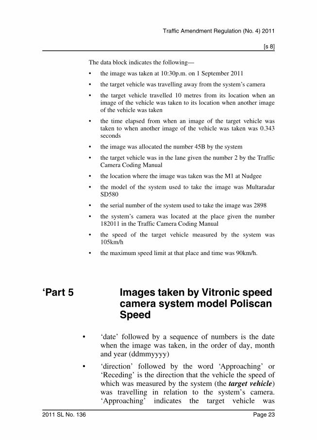
The data block indicates the following—
• the image was taken at 10:30p.m. on 1 September 2011
• the target vehicle was travelling away from the system’s camera
• the target vehicle travelled 10 metres from its location when animage of the vehicle was taken to its location when another imageof the vehicle was taken
• the time elapsed from when an image of the target vehicle wastaken to when another image of the vehicle was taken was 0.343seconds
• the image was allocated the number 45B by the system
• the target vehicle was in the lane given the number 2 by the TrafficCamera Coding Manual
• the location where the image was taken was the M1 at Nudgee
• the model of the system used to take the image was MultaradarSD580
• the serial number of the system used to take the image was 2898
• the system’s camera was located at the place given the number182011 in the Traffic Camera Coding Manual
• the speed of the target vehicle measured by the system was105km/h
• the maximum speed limit at that place and time was 90km/h.
‘Part 5 Images taken by Vitronic speed camera system model Poliscan Speed
• ‘date’ followed by a sequence of numbers is the datewhen the image was taken, in the order of day, monthand year (ddmmyyyy)
• ‘direction’ followed by the word ‘Approaching’ or‘Receding’ is the direction that the vehicle the speed ofwhich was measured by the system (the target vehicle)was travelling in relation to the system’s camera.‘Approaching’ indicates the target vehicle was
2011 SL No. 136 Page 23

[s 8]
Traffic Amendment Regulation (No. 4) 2011
travelling towards the camera and ‘Receding’ indicatesthe target vehicle was travelling away from the camera
• ‘image no’ followed by writing is the number allocatedby the system to the image
• ‘lane’ followed by a number is the number for the lanein which the target vehicle was travelling, with thehighest number being closest to the camera
• ‘limit’ followed by a number is the maximum speedlimit, in kilometres per hour, for the place at which theimage was taken when the image was taken
• ‘location’ followed by writing is the name of thelocation where the image was taken
• ‘location code’ followed by a number is the numbergiven in the Traffic Camera Coding Manual for thelocation of the system’s camera when the image wastaken
• ‘speed’ followed by a number is the speed, in kilometresper hour, of the target vehicle measured by the systemwhen the image was taken
• ‘system’ followed by writing is the device type andserial number of the system used to take the image
• ‘time’ followed by a sequence of numbers is the time in24-hour clock mode when the image was taken in theorder of hour, minute and second
• a symbol of a rectangle or a square on a vehicle shownin the image indicates the vehicle is the target vehicle.
Example—
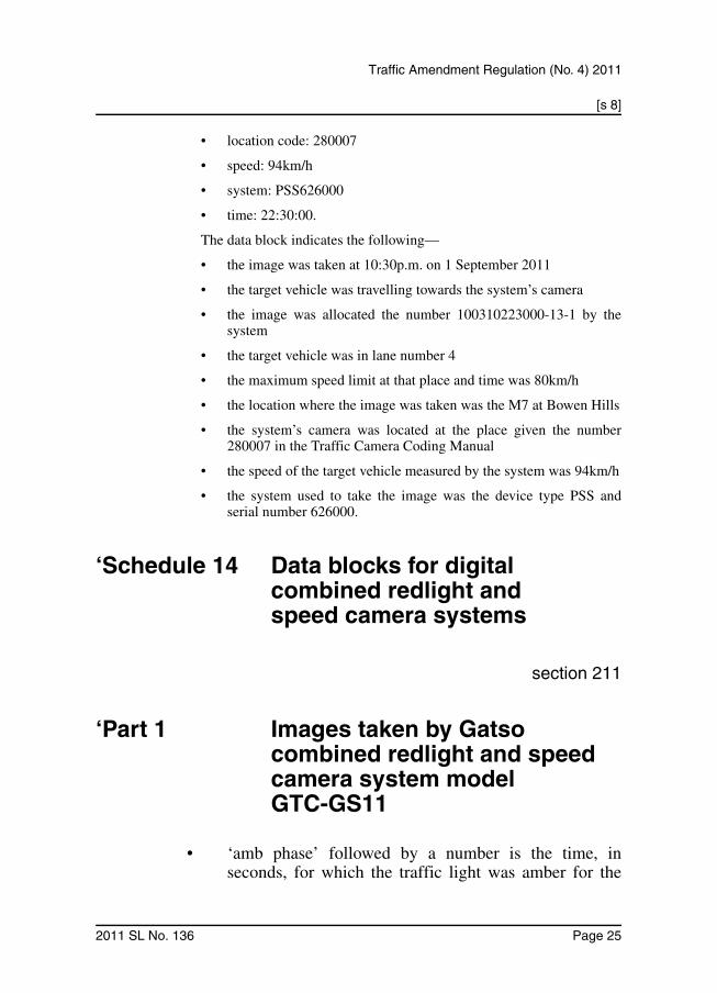
A data block may show the following information—
• date: 01/09/2011
• direction: Approaching
• image no: 100310223000-13-1
• lane: 4
• limit: 80km/h
• location: M7 Bowen Hills
Page 24 2011 SL No. 136
[s 8]
Traffic Amendment Regulation (No. 4) 2011
• location code: 280007
• speed: 94km/h
• system: PSS626000
• time: 22:30:00.
The data block indicates the following—
• the image was taken at 10:30p.m. on 1 September 2011
• the target vehicle was travelling towards the system’s camera
• the image was allocated the number 100310223000-13-1 by thesystem
• the target vehicle was in lane number 4
• the maximum speed limit at that place and time was 80km/h
• the location where the image was taken was the M7 at Bowen Hills
• the system’s camera was located at the place given the number280007 in the Traffic Camera Coding Manual
• the speed of the target vehicle measured by the system was 94km/h
• the system used to take the image was the device type PSS andserial number 626000.
‘Schedule 14 Data blocks for digital combined redlight and speed camera systems
section 211
‘Part 1 Images taken by Gatso combined redlight and speed camera system model GTC-GS11
• ‘amb phase’ followed by a number is the time, inseconds, for which the traffic light was amber for the
2011 SL No. 136 Page 25

[s 8]
Traffic Amendment Regulation (No. 4) 2011
traffic light cycle immediately before the red phase thatis recorded on the data block
• ‘date’ followed by a sequence of numbers is the datewhen the image was taken, in the order of day, monthand year (ddmmyyyy)
• ‘direction’ followed by the letter ‘A’ or ‘F’ is thedirection that the vehicle that activated the system’scamera (the target vehicle) was travelling in relation tothe camera. ‘A’ indicates the target vehicle wastravelling away from the camera and ‘F’ indicates thetarget vehicle was travelling towards the camera
• ‘dist interval’ followed by a number is the distancetravelled by the target vehicle, in metres, from itslocation when an image of the vehicle was taken to itslocation when another image of the vehicle was taken
• ‘elapsed time’ followed by a number is the time elapsed,in seconds, from when an image of the target vehiclewas taken to when another image of the vehicle wastaken
• ‘image no’ followed by a number is the numberallocated by the system to the image
• ‘lane’ followed by a number is the number given in theTraffic Camera Coding Manual for the lane in which thetarget vehicle was travelling, with the highest numberbeing furthest from the camera
• ‘location’ followed by writing is the name of thelocation where the image was taken
• ‘model’ followed by writing is the model of the systemused to take the image
• ‘red phase’ followed by a number is the time elapsed, inseconds, from when the traffic light changed to red towhen the image was taken
• ‘serial no’ followed by writing is the serial number ofthe system used to take the image
Page 26 2011 SL No. 136

[s 8]
Traffic Amendment Regulation (No. 4) 2011
• ‘site code’ followed by a number is the number given inthe Traffic Camera Coding Manual for the location ofthe system’s camera when the image was taken
• ‘speed’ followed by a number is the speed, in kilometresper hour, of the target vehicle measured by the systemwhen the image was taken
• ‘speed limit’ followed by a number is the maximumspeed limit, in kilometres per hour, for the place atwhich the image was taken when the image was taken
• ‘time’ followed by a sequence of numbers is the time in24-hour clock mode when the image was taken in theorder of hour, minute and second.
Example—
A data block may show the following information—
• date: 01/09/2011
• direction: A
• dist interval: 10m
• elapsed time: 0.486s
• image no: 45
• lane: 2
• location: Gympie Road, Kedron
• model: GTC-GS11
• red phase: 2.3s
• serial no: 2898
• site code: 180005
• speed: 74km/h
• speed limit: 60km/h
• time: 22:30:00.
The data block indicates the following—
• the image was taken at 10:30p.m. on 1 September 2011
• the target vehicle was travelling away from the system’s camera
2011 SL No. 136 Page 27

[s 8]
Traffic Amendment Regulation (No. 4) 2011
• the target vehicle travelled 10 metres from its location when animage of the vehicle was taken to its location when another imageof the vehicle was taken
• the time elapsed from when an image of the target vehicle wastaken to when another image of the vehicle was taken was 0.486seconds
• the image was allocated the number 45 by the system
• the target vehicle was in the lane given the number 2 in the TrafficCamera Coding Manual
• the location where the image was taken was Gympie Road atKedron
• the model of the system used to take the image was GTC-GS11
• the image was taken 2.3 seconds after the traffic light changed tored
• the serial number of the system used to take the image was 2898
• the system’s camera was located at the place given the number180005 in the Traffic Camera Coding Manual
• the speed of the target vehicle measured by the system was 74km/h
• the maximum speed limit at that place and time was 60km/h.
‘Part 2 Images taken by Redflex combined redlight and speed camera system models SR101, SR102, SR103, SR104, SR105 and SR106
• ‘date’ followed by a sequence of numbers is the datewhen the image was taken, in the order of day, monthand year (ddmmyyyy)
• ‘direction’ followed by the word ‘Away’ or ‘Towards’ isthe direction that the vehicle that activated the system’scamera (the target vehicle) was travelling in relation tothe camera. ‘Away’ indicates the target vehicle wastravelling away from the camera and ‘Towards’
Page 28 2011 SL No. 136

[s 8]
Traffic Amendment Regulation (No. 4) 2011
indicates the target vehicle was travelling towards thecamera
• ‘dist interval’ followed by a number is the distancetravelled by the target vehicle, in metres, from itslocation when an image of the vehicle was taken to itslocation when another image of the vehicle was taken
• ‘elapsed time’ followed by a number is the time elapsed,in seconds, from when an image of the target vehiclewas taken to when another image of the vehicle wastaken
• ‘image no’ followed by a number is the numberallocated by the system to the image
• ‘lane’ followed by a number is the number given in theTraffic Camera Coding Manual for the lane in which thetarget vehicle was travelling, with the highest numberbeing furthest from the camera
• ‘location’ followed by writing is the name of thelocation where the image was taken
• ‘model’ followed by writing is the model of the systemused to take the image
• ‘phase’ followed by writing is the traffic light phasewhen the image was taken (the relevant phase)
• ‘phase duration’ followed by a number is the timeelapsed, in seconds, from when the traffic light changedto the relevant phase to when the image was taken
• ‘serial no’ followed by writing is the serial number ofthe system used to take the image
• ‘site code’ followed by a number is the number given inthe Traffic Camera Coding Manual for the location ofthe system’s camera when the image was taken
• ‘speed’ followed by a number is the speed, in kilometresper hour, of the target vehicle measured by the systemwhen the image was taken
2011 SL No. 136 Page 29

[s 8]
Traffic Amendment Regulation (No. 4) 2011
• ‘speed limit’ followed by a number is the maximumspeed limit, in kilometres per hour, for the place atwhich the image was taken when the image was taken
• ‘time’ followed by a sequence of numbers is the time in24-hour clock mode when the image was taken in theorder of hour, minute and second.
Example—
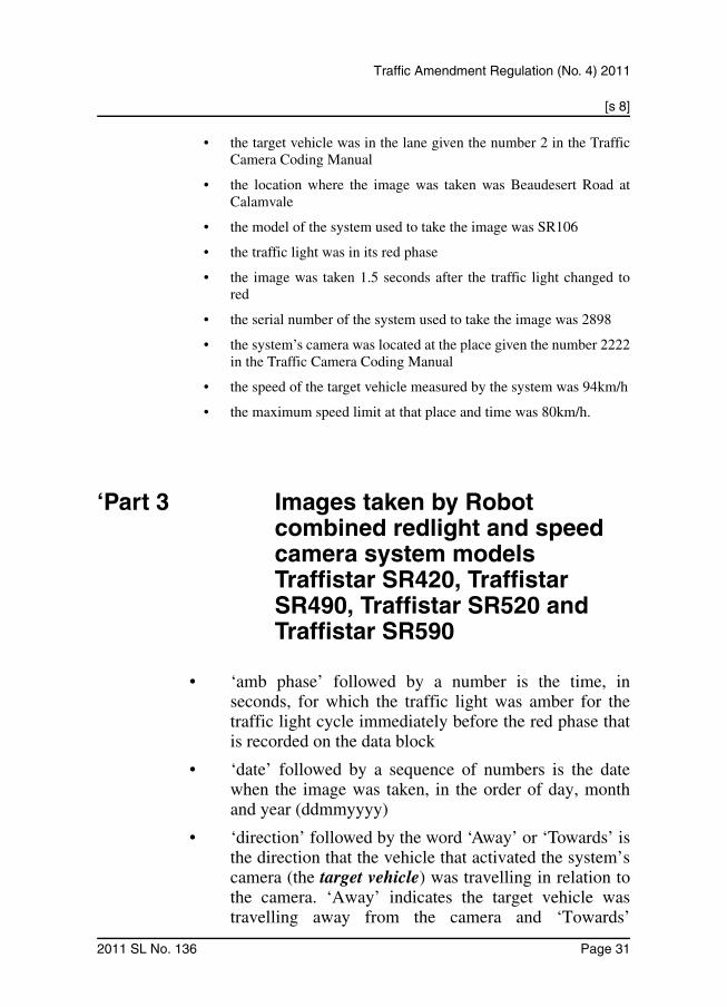
A data block may show the following information—
• date: 01/09/2011
• direction: Away
• dist interval: 10m
• elapsed time: 0.383s
• image no: 45
• lane: 2
• location: Beaudesert Road, Calamvale
• model: SR106
• phase: red
• phase duration: 1.50s
• serial no: 2898
• site code: 2222
• speed: 94km/h
• speed limit: 80km/h
• time: 07:35:00.
The data block indicates the following—
• the image was taken at 7:35a.m. on 1 September 2011
• the target vehicle was travelling away from the system’s camera
• the target vehicle travelled 10 metres from its location when animage of the vehicle was taken to its location when another imageof the vehicle was taken
• the time elapsed from when an image of the target vehicle wastaken to when another image of the vehicle was taken was 0.383seconds
• the image was allocated the number 45 by the system
Page 30 2011 SL No. 136
[s 8]
Traffic Amendment Regulation (No. 4) 2011
• the target vehicle was in the lane given the number 2 in the TrafficCamera Coding Manual
• the location where the image was taken was Beaudesert Road atCalamvale
• the model of the system used to take the image was SR106
• the traffic light was in its red phase
• the image was taken 1.5 seconds after the traffic light changed tored
• the serial number of the system used to take the image was 2898
• the system’s camera was located at the place given the number 2222in the Traffic Camera Coding Manual
• the speed of the target vehicle measured by the system was 94km/h
• the maximum speed limit at that place and time was 80km/h.
‘Part 3 Images taken by Robot combined redlight and speed camera system models Traffistar SR420, Traffistar SR490, Traffistar SR520 and Traffistar SR590
• ‘amb phase’ followed by a number is the time, inseconds, for which the traffic light was amber for thetraffic light cycle immediately before the red phase thatis recorded on the data block
• ‘date’ followed by a sequence of numbers is the datewhen the image was taken, in the order of day, monthand year (ddmmyyyy)
• ‘direction’ followed by the word ‘Away’ or ‘Towards’ isthe direction that the vehicle that activated the system’scamera (the target vehicle) was travelling in relation tothe camera. ‘Away’ indicates the target vehicle wastravelling away from the camera and ‘Towards’
2011 SL No. 136 Page 31

[s 8]
Traffic Amendment Regulation (No. 4) 2011
indicates the target vehicle was travelling towards thecamera
• ‘dist interval’ followed by a number is the distancetravelled by the target vehicle, in metres, from itslocation when an image of the vehicle was taken to itslocation when another image of the vehicle was taken
• ‘elapsed time’ followed by a number is the time elapsed,in seconds, from when an image of the target vehiclewas taken to when another image of the vehicle wastaken
• ‘image no’ followed by a number is the numberallocated by the system to the image
• ‘lane’ followed by a number is the number given in theTraffic Camera Coding Manual for the lane in which thetarget vehicle was travelling, with the highest numberbeing furthest from the camera
• ‘location’ followed by writing is the name of thelocation where the image was taken
• ‘model’ followed by writing is the model of the systemused to take the image
• ‘red phase’ followed by a number is the time elapsed, inseconds, from when the traffic light changed to red towhen the image was taken
• ‘serial no’ followed by writing is the serial number ofthe system used to take the image
• ‘site code’ followed by a number is the number given inthe Traffic Camera Coding Manual for the location ofthe system’s camera when the image was taken
• ‘speed’ followed by a number is the speed, in kilometresper hour, of the target vehicle measured by the systemwhen the image was taken
• ‘speed limit’ followed by a number is the maximumspeed limit, in kilometres per hour, for the place atwhich the image was taken when the image was taken
Page 32 2011 SL No. 136

[s 8]
Traffic Amendment Regulation (No. 4) 2011
• ‘time’ followed by a sequence of numbers is the time in24-hour clock mode when the image was taken in theorder of hour, minute and second.
Example—
A data block may show the following information—
• date: 01/09/2011
• direction: Away
• dist interval: 10m
• elapsed time: 0.486s
• image no: 45B
• lane: 2
• location: Waterworks Road, Ashgrove
• model: Traffistar SR520
• red phase: 002.88s
• serial no: 3444
• site code: 1053
• speed: 74km/h
• speed limit: 60km/h
• time: 13:15:00.
The data block indicates the following—
• the image was taken at 1:15p.m. on 1 September 2011
• the target vehicle was travelling away from the system’s camera
• the target vehicle travelled 10 metres from its location when animage of the vehicle was taken to its location when another imageof the vehicle was taken
• the time elapsed from when an image of the target vehicle wastaken to when another image of the vehicle was taken was 0.486seconds
• the image was allocated the number 45B by the system
• the target vehicle was in the lane given the number 2 in the TrafficCamera Coding Manual
• the location where the image was taken was Waterworks Road atAshgrove
2011 SL No. 136 Page 33

[s 8]
Traffic Amendment Regulation (No. 4) 2011
• the model of the system used to take the image was TraffistarSR520
• the image was taken 2.88 seconds after the traffic light changed tored
• the serial number of the system used to take the image was 3444
• the system’s camera was located at the place given the number 1053in the Traffic Camera Coding Manual
• the speed of the target vehicle measured by the system was 74km/h
• the maximum speed limit at that place and time was 60km/h.
‘Schedule 15 Data blocks for digital point-to-point camera system—images taken by Redflex point-to-point camera system models P2P101, P2P102, P2P103, P2P104, P2P105 and P2P106
section 211
• ‘date’ followed by a sequence of numbers is the datewhen the image was taken, in the order of day, monthand year (ddmmyyyy)
• ‘direction’ followed by the word ‘Away’ or ‘Towards’ isthe direction that the vehicle that activated the system’scamera (the target vehicle) was travelling in relation tothe system’s camera. ‘Away’ indicates the target vehiclewas travelling away from the camera and ‘Towards’indicates the target vehicle was travelling towards thecamera
• ‘dist interval’ followed by a number is the distancetravelled by the target vehicle, in metres, from its
Page 34 2011 SL No. 136

[s 8]
Traffic Amendment Regulation (No. 4) 2011
location when an image of the vehicle was taken to itslocation when another image of the vehicle was taken
• ‘elapsed time’ followed by a number is the time elapsed,in seconds, from when an image of the target vehiclewas taken to when another image of the vehicle wastaken
• ‘image no’ followed by a number is the numberallocated by the system to the image
• ‘lane’ followed by a number is the number given in theTraffic Camera Coding Manual for the lane in which thetarget vehicle was travelling, with the highest numberbeing furthest from the camera
• ‘location’ followed by writing is the name of thelocation where the image was taken
• ‘model’ followed by writing is the model of the systemused to take the image
• ‘serial no’ followed by writing is the serial number ofthe system used to take the image
• ‘site code’ followed by a number is the number given inthe Traffic Camera Coding Manual for the location ofthe system’s camera when the image was taken
• ‘speed’ followed by a number is the speed, in kilometresper hour, of the target vehicle measured by the systemwhen the image was taken
• ‘speed limit’ followed by a number is the maximumspeed limit, in kilometres per hour, for the place atwhich the image was taken when the image was taken
• ‘time’ followed by a sequence of numbers is the time in24-hour clock mode when the image was taken in theorder of hour, minute and second.
Example of a data block for an image taken by 1 of the system’s cameras ofa vehicle at a point on a road used, in conjunction with another imagetaken by 1 of the system’s other cameras at a different point, to calculatethe average speed of the vehicle under the Act, section 120A—
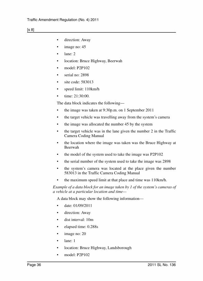
A data block may show the following information—
• date: 01/09/2011
2011 SL No. 136 Page 35
[s 8]
Traffic Amendment Regulation (No. 4) 2011
• direction: Away
• image no: 45
• lane: 2
• location: Bruce Highway, Beerwah
• model: P2P102
• serial no: 2898
• site code: 583013
• speed limit: 110km/h
• time: 21:30:00.
The data block indicates the following—
• the image was taken at 9:30p.m. on 1 September 2011
• the target vehicle was travelling away from the system’s camera
• the image was allocated the number 45 by the system
• the target vehicle was in the lane given the number 2 in the TrafficCamera Coding Manual
• the location where the image was taken was the Bruce Highway atBeerwah
• the model of the system used to take the image was P2P102
• the serial number of the system used to take the image was 2898
• the system’s camera was located at the place given the number583013 in the Traffic Camera Coding Manual
• the maximum speed limit at that place and time was 110km/h.
Example of a data block for an image taken by 1 of the system’s cameras ofa vehicle at a particular location and time—
A data block may show the following information—
• date: 01/09/2011
• direction: Away
• dist interval: 10m
• elapsed time: 0.288s
• image no: 20
• lane: 1
• location: Bruce Highway, Landsborough
• model: P2P102
Page 36 2011 SL No. 136

[s 8]
Traffic Amendment Regulation (No. 4) 2011
• serial no: 2898
• site code: 583012
• speed: 125km/h
• speed limit: 110km/h
• time: 21:35:00.
The data block indicates the following—
• the image was taken at 9:35p.m. on 1 September 2011
• the target vehicle was travelling away from the system’s camera
• the target vehicle travelled 10 metres from its location when animage of the vehicle was taken to its location when another imageof the vehicle was taken
• the time elapsed from when an image of the target vehicle wastaken to when another image of the vehicle was taken was 0.288seconds
• the image was allocated the number 20 by the system
• the target vehicle was in the lane given the number 1 in the TrafficCamera Coding Manual
• the location where the image was taken was the Bruce Highway atLandsborough
• the model of the system used to take the image was P2P102
• the serial number of the system used to take the image was 2898
• the system’s camera was located at the place given the number583012 in the Traffic Camera Coding Manual
• the speed of the target vehicle measured by the system was125km/h
• the maximum speed limit at that place and time was 110km/h.’.
ENDNOTES1 Made by the Governor in Council on 7 July 2011.2 Notified in the gazette on 8 July 2011.3 Laid before the Legislative Assembly on . . .4 The administering agency is the Department of Transport and Main Roads.
2011 SL No. 136 Page 37

© State of Queensland 2011