traditional series framing - fs.hubspotusercontent00.net
TRANSCRIPT

This framing guide is a reference for a typical Ortal Traditional Series fireplace installation. This list is not exhaustive and does not supplement thorough review of the installation manual.
Page 1 of 8
Traditional Series Framing Combustible Framing Non-Combustible Framing
Dimension A: Rough Combustible Framing Opening Height Dimension B: Rough Framing Opening Width Dimension C: Framing Depth Dimension D: Firestop Opening Dimension E: Non-combustible Framing Zone
Dimension A: Rough Framing Opening Height Dimension B: Rough Framing Opening Width Dimension C Framing Depth Dimension D: Firestop Opening
WARNING – MAINTAIN AIR FLOW CLEARANCE: Firebox top vent must have minimum 4” of clearance to any material achieve sufficient airflow. Failure to do so could result in improper fireplace operation, property damage, or physical injury. Review “General Clearances” section prior to framing to ensure all clearances are followed.
Model Framing Dimension A Dimension B Dimension C Dimension D Dimension E
TR 90 Combustible 51 7/8” 46 1/8” 27” Refer to pipe
manufacturer’s firestop
dimensions
13 3/8” Non-Combustible 37 7/8” 44 7/8” 26 1/2” N/A
TR 110 Combustible 54 3/8” 53 5/8” 27” 13 3/8”
Non-Combustible 41 1/8” 52 3/8” 26 1/2” N/A
NOTE: Traditional series fireplaces require 5/8” Type X Drywall on both the interior and exterior sides of the chase when framing with combustible material.
Page 2 of 8
Building Around the Fireplace
Building Checklist The following building checklist is a quick reference for a typical Ortal Traditional series fireplace installation. This list is not exhaustive and does not supplement thorough review of the installation manual.
Fireplace Location: Ensure the location allows for min. 36” clearance from viewing area to combustibles and 12” to non-combustibles. Make sure a clear path is established to allow the fireplace to be safely transported to installation location.
Venting: Confirm vent size (5”x8” for natural vent and 3”x5” for power vent), vent clearance (1” on sides and bottom, 3” on top), vent configuration, and termination location.
Height from Floor: Fireplace sits directly on the floor. Distance from the floor to bottom viewing area is 1 5/8”. If desired viewing area location on the wall is higher than 1 5/8”, a platform can be built for the fireplace to sit on.
Chase Floor/Platform: Fireplace can stand on the chase floor or a platform. Floor or platform must be able to bear the weight of the fireplace. It can be constructed out of wood, concrete, metal, or any other solid materials (not required to be non-combustible).
Chase Construction: No materials can be attached directly to the fireplace (exception: 5/8” Type X Drywall). The area of the chase interior must meet minimum chase area requirements (depending on the model). All chases require a heat release.
Framing: Adhere to minimum framing dimensions (or greater). Keep min. 2” clearance from back and sides (as applicable by model) of fireplace to any material. The first 18” above the top of the fireplace viewing area must always be non-combustible framing. Maintain min. 1/4” clearance from front face of fireplace and front metal off-set to the framing. Maintain min. 4” space between air vents at top of fireplace to any material. For recessed fireplaces, do not exceed 12” max. front overhang depth limit. No material is permitted to extend past the metal lip surrounding the fireplace viewing area to allow for glass removal.
5/8” Type X Drywall Requirements: One layer of 5/8” Type X Drywall (or equivalent) must be installed on the exterior of the chase framing. When framing with combustible material and/or installing a TV above the fireplace, a layer of 5/8” Type X Drywall must be installed on the interior of the chase framing as well.
TV/Artwork: TV/Art must be min. 12” above top of fireplace viewing area.
Gas Supply Line and Power Location: Locate gas line with manual shut off according to local code. Power provided by single gang 120V outlet in same area as gas line.
Access Panel: Not required for Traditional series fireplaces (unless power venting).
Heat Release: Crucial for Cool Wall Technology. Must start within 6” (max.) from the chase’s ceiling. Heat release must meet minimum size (depending on the model) of net free air space. Height of the heat release must not exceed 1/3 of the width.
Air Intake: Not required for Traditional series fireplaces.
Finishing: For finishes flush to the fireplace, no clearances are required. For finishes where the fireplace is recessed to the finish, maintain 1/8" from the finish to the front face of the fireplace.

Page 3 of 8
Framing Fireplace chase may be framed with either combustible (typically wood studs) or non-combustible framing (typically metal studs). Any framing within 18 inches from the top of the fireplace glass (viewing area) must be non-combustible. This does not apply to the framing to the back or side(s) of the fireplace; these may be combustible.
The fireplace is non-load bearing. The framing of the fireplace chase must be designed to carry the entire weight of the wall and finish material. Surrounding material must not transfer weight to the fireplace (exception: 5/8” Type X drywall or equivalent), or be connected in any way to the fireplace.
No material is permitted to extend past the metal lip surrounding the fireplace viewing area. This area must be unobstructed to allow the heat barrier and inside glass panel to be removable.
5/8” Type X Drywall Requirements
Exterior side (i.e., room-facing side) of the framing must be covered with 5/8” Type X Drywall (or equivalent). Finish material is installed on top of the drywall. This applies to combustible and non-combustible framing.
When building with combustible framing, or installing a TV/Artwork above the fireplace, an additional layer of 5/8” Type X Drywall is required to line the inside of the chase as well.
No material is permitted to extend past the metal lip surrounding the fireplace viewing area. This area must be unobstructed to allow the heat barrier and inside glass panel to be removable.
Chase Floor/Platform
The fireplace must be installed on a flat, solid, continuous surface. Surface can be wood, concrete, metal, and other typical solid floor types. Surface material is not required to be non-combustible.
The fireplaces sit directly on the floor and do not have any legs. The distance from the bottom of the fireplace to the bottom of the viewing area is 1 5/8”.
Raised Platform Option: To raise the fireplace higher than 1 5/8”, build a platform for the fireplace to stand on. Platform must be stable and able to bear the full weight of the fireplace. Platform can be constructed out of wood, concrete, metal, or any other solid materials. Platform material is not required to be non-combustible.
Hearth Extension A hearth extension is not required. Any hearth extension used is for appearance only and does not have to conform to a standard hearth extension installation requirement.

Page 4 of 8
General Clearances Viewing Area Clearances The viewing area clearance zone is an area that extends perpendicular from the fireplace viewing area. The depth of the viewing area clearance zone depends on the combustibility of the material in question. Distance is measured from the fireplace heat barrier.
Non-Combustible Materials Must be minimum 12 inches from fireplace viewing area. Combustible Materials Must be minimum 36 inches from fireplace viewing area.
Materials (including combustible flooring and combustible finish material) are permitted below and around the viewing area clearance zone.
Firebox Clearance Maintain a 2-inch clearance from the back and/or side of the fireplace (depending on the model) to any material.
Clearance to Chase Ceiling Maintain a 12-inch clearance from the top of the fireplace viewing area to the lowest point of the ceiling or to any building materials.
NOTES: A heat release is required for every installation, but it is not required to be split between the two sides of the chase as shown
in the diagram above. It is shown in this diagram for illustrative purposes only. See the “Heat Release Requirements” section of the installation manual for details.
Clearance around the vent pipe must be maintained (1” clearance on the sides and bottom, 3” on top).
Page 5 of 8
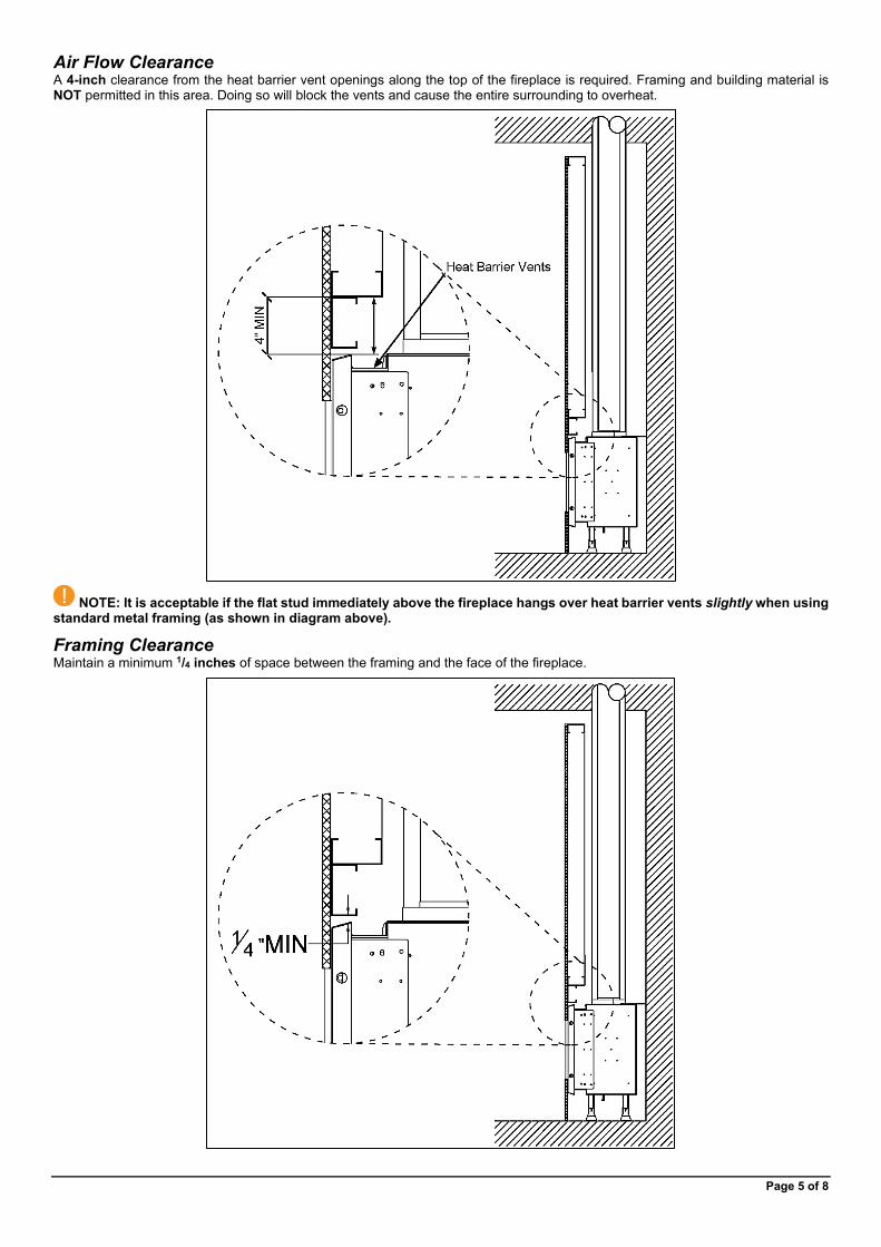
Air Flow Clearance A 4-inch clearance from the heat barrier vent openings along the top of the fireplace is required. Framing and building material is NOT permitted in this area. Doing so will block the vents and cause the entire surrounding to overheat.
NOTE: It is acceptable if the flat stud immediately above the fireplace hangs over heat barrier vents slightly when using standard metal framing (as shown in diagram above).
Framing Clearance Maintain a minimum 1/4 inches of space between the framing and the face of the fireplace.

Page 6 of 8
Clearance to a Side Wall The fireplace viewing area is zero-clearance to a side wall. A side wall is defined as a wall that meets the viewing area at a 90° angle.
Alcove Side Walls (Top View)
= Building Material
The temperature on the side wall can get as high as 150°F above ambient temperature. While the fireplace certification allows for this temperature variance, building and finish materials will have their own limitations. Consult the material manufacturer to ensure the material can safety withstand this temperature range.
This information does not apply to a wall that is constructed in front of the viewing area. For materials that will be in front of a main or side viewing area, please refer to the “Viewing Area Clearances” section.
Maximum Overhang Depth Overhang depth of a recessed fireplace must not exceed the clearances shown in the diagram below. Overhang depth is measured from the edge of the fireplace lip to the out-most part of the wall (including finish material).
Bottom recess (or “hearth extension”) has no minimum or maximum depth requirement. If bottom recess depth exceeds 12 inches, ensure the structure is capable of supporting the weight of a fireplace technician for servicing.
Page 7 of 8
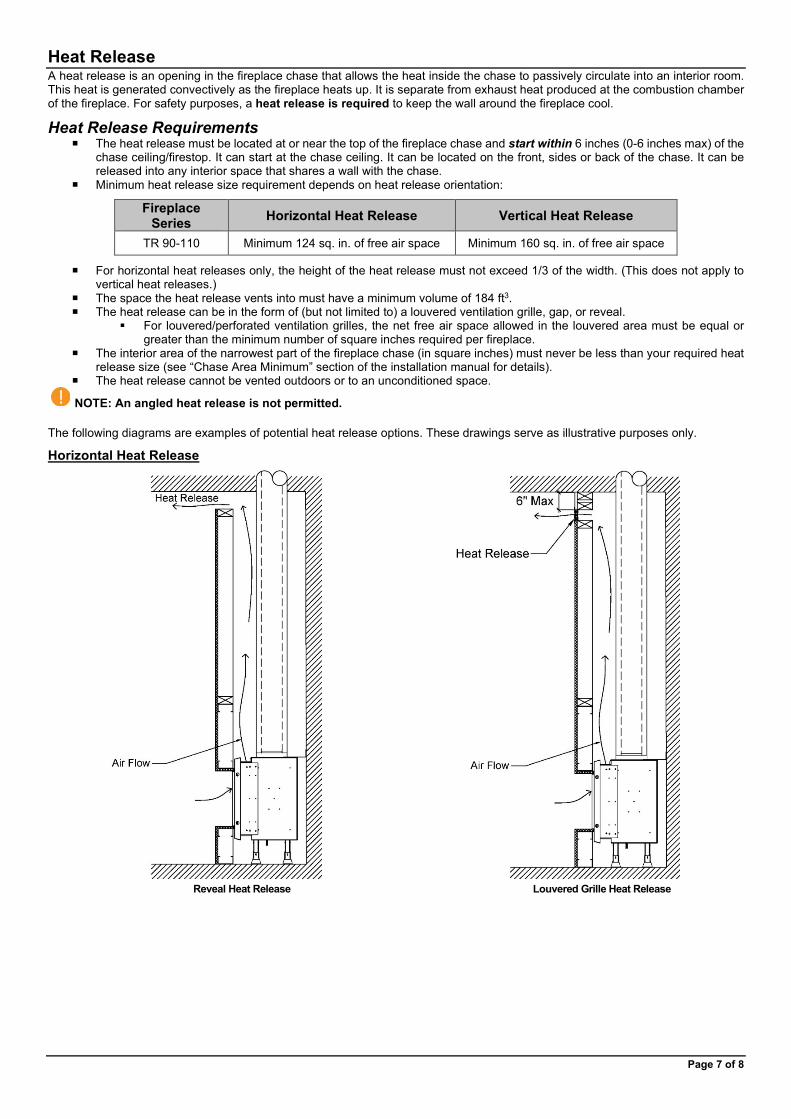
Heat Release A heat release is an opening in the fireplace chase that allows the heat inside the chase to passively circulate into an interior room. This heat is generated convectively as the fireplace heats up. It is separate from exhaust heat produced at the combustion chamber of the fireplace. For safety purposes, a heat release is required to keep the wall around the fireplace cool.
Heat Release Requirements The heat release must be located at or near the top of the fireplace chase and start within 6 inches (0-6 inches max) of the
chase ceiling/firestop. It can start at the chase ceiling. It can be located on the front, sides or back of the chase. It can be released into any interior space that shares a wall with the chase.
Minimum heat release size requirement depends on heat release orientation:
Fireplace Series Horizontal Heat Release Vertical Heat Release
TR 90-110 Minimum 124 sq. in. of free air space Minimum 160 sq. in. of free air space
For horizontal heat releases only, the height of the heat release must not exceed 1/3 of the width. (This does not apply to vertical heat releases.)
The space the heat release vents into must have a minimum volume of 184 ft3. The heat release can be in the form of (but not limited to) a louvered ventilation grille, gap, or reveal.
For louvered/perforated ventilation grilles, the net free air space allowed in the louvered area must be equal or greater than the minimum number of square inches required per fireplace.
The interior area of the narrowest part of the fireplace chase (in square inches) must never be less than your required heat release size (see “Chase Area Minimum” section of the installation manual for details).
The heat release cannot be vented outdoors or to an unconditioned space.
NOTE: An angled heat release is not permitted.
The following diagrams are examples of potential heat release options. These drawings serve as illustrative purposes only.
Horizontal Heat Release
Reveal Heat Release Louvered Grille Heat Release

Page 8 of 8
Access Panel The Traditional series has an access panel built in on the left side of the interior of the firebox and does not need an access panel incorporated into the fireplace chase. This access panel is hidden behind a removable decorative interior panel, and opens to the gas and electrical components, which have been built onto the left side of the unit. To access these components, remove screen heat barrier, interior glass, and left decorative side panel, and access components through the access panel door.
Traditional Series Interior Access Panel
An access panel is not required (see notes below for exception), but it is highly recommended. It allows for access to the fireplace’s gas and electrical components for servicing.
NOTE: An access panel, or some other form of clear access, is required for power vented fireplaces. For servicing purposes, the power vent control box (located at the fireplace) must be easily accessible in a way that does not require removal of the fireplace glass.