tracphone v7-ip user's guide - home - ca...
TRANSCRIPT

User’s Guide
TracPhone® V7IP26" (66 cm) Configuration
TracPhone V7-IP User’s Guide
KVH Part # 54-0783 Rev. A© 2012, KVH Industries, Inc., All rights reserved.
TracPhone V7-IPUser’s GuideThis user’s guide provides all of the basic information you need to operate, set up, troubleshoot, and maintain the TracPhone V7-IP system. For detailed installation information, please refer to the TracPhone V7-IP Installation Guide.
If you have any comments regarding this manual, please e-mail them to [email protected]. Your input is greatly appreciated!
Technical SupportWithin the Continental U.S.A.:Phone: 1 866 701-7103E-mail: [email protected]
North/South America, Australia:Phone: +1 401 851-3806E-mail: [email protected]
Europe, Middle East, Asia, Africa:Phone: +45 45 160 180E-mail: [email protected]
Trademark InformationTracPhone, KVH, CommBox, and the unique light-colored dome with dark contrasting baseplate are trademarks of KVH Industries, Inc.mini-VSAT Broadband is a service mark of KVH Industries, Inc.ViaSat and the ViaSat logo are registered trademarks of ViaSat, Inc.All other trademarks are the property of their respective owners.
DisclaimerEvery effort has been made to ensure the correctness and completeness of the material in this document. No company shall be liable for errors contained herein. The information in this document is subject to change without notice. No warranty of any kind is made with regard to this material, including, but not limited to, the implied warranties of merchantability and fitness for a particular purpose.
TracPhone V7-IP User’s Guide
i
Table of Contents1 Introduction
About this Manual ..............................................................................3
Who Should Use this Manual....................................................3
Icons Used in this Manual ........................................................3
Typographical Conventions ......................................................3
Related Documentation ............................................................4
Important Safety Information.............................................................5
RF Radiation Hazard Area.........................................................6
System Overview ...............................................................................7
System Components.................................................................8
Satellite Communications ..................................................................9
2 Getting Started
Service Activation ............................................................................13
Contacting KVH’s Satellite Airtime & Product Activation Department............................................................14
Turning On the System ....................................................................15
System Startup ................................................................................16
Accessing the Web Interface ...........................................................17
Understanding the Home Page ........................................................18
Viewing the Help (User Documentation) ..........................................19
3 Interface Preferences
Changing the Administrator Password ............................................23
Entering the Vessel Name................................................................24
Assigning Phone Line Names ..........................................................25
Adjusting the LCD Brightness ..........................................................26
TracPhone V7-IP User’s Guide
ii
4 No-Transmit Zones
No-Transmit Zones Overview...........................................................29
Status of No-Transmit Zones ...........................................................30
Establishing No-Transmit Zones ......................................................31
Disabling No-Transmit Zones...........................................................33
Clearing No-Transmit Zones ............................................................34
5 Voice Connections
Voice Service Overview....................................................................37
How the Voice Service Works.................................................37
Making a Ship-to-Shore Call............................................................38
Making a Shore-to-Ship Call............................................................40
Adding Phone Lines .........................................................................41
Additional MTA(s) ...................................................................42
Crew Calling Gateway.............................................................43
Virtual Numbers ...............................................................................44
VoiceMail .........................................................................................45
Recording a VoiceMail Personal Greeting...............................45
Listening to Your VoiceMail Messages ...................................45
Faxing ..............................................................................................47
UCH-250 Fax Server ...............................................................48
Accessing Your Voice Account.........................................................49
6 Network Configuration
Wired DHCP Configuration ...............................................................53
Wireless DHCP Configuration...........................................................54
Wireless Settings on CommBox-ACU......................................55
TracPhone V7-IP User’s Guide
Configuring Computers for DHCP.....................................................57
Windows 7 or Windows Vista DHCP Settings .........................57
Windows XP DHCP Settings ...................................................58
Mac OS X DHCP Settings........................................................60
Static IP Configuration .....................................................................61
LAN Settings on CommBox-ACU......................................................64
Cache Settings on CommBox-ACU ..................................................65
CommBox Settings on CommBox-ACU ............................................66
7 Data Connections
Internet Access Overview ................................................................69
Connecting to the Internet......................................................69
Tips for Minimizing Data Usage.......................................................70
Preventing Automatic Updates...............................................71
Firewall Protection .................................................................71
Web Browser Settings............................................................72
Data-Intensive Applications ...................................................75
Mobile Websites.....................................................................75
E-mail Best Practices .............................................................76
CommBox Features .........................................................................77
Accessing the CommBox Web Interface ................................77
8 Troubleshooting
Initial Steps for Any Problem ...........................................................81
Troubleshooting a Voice Problem....................................................83
Troubleshooting a Data Problem .....................................................85
Error Messages................................................................................87
Status Information ...........................................................................91
Status Information on the Web Interface ...............................91
Status Information on the CommBox-ACU Front Panel LCD...97
iii
TracPhone V7-IP User’s Guide
iv
LED Indicators................................................................................101
System Logs ..................................................................................104
Operational Log ....................................................................104
Event Log..............................................................................105
Equipment ID Numbers ..................................................................106
Software Versions..........................................................................107
Technical Support ..........................................................................108
Remote Diagnostics..............................................................109
9 Maintenance
Preventive Maintenance ................................................................113
Software Updates ..........................................................................114
Using the CommBox-ACU to Update Software .....................115
Using Your Computer to Update Software............................116
Using an iPhone/iPod touch to Update Software..................117
Using a USB Flash Drive to Update Software .......................118
Modem Configuration Updates ......................................................119
Manually Updating the Modem’s Configuration Files ...........120
Corrective Maintenance.................................................................124
Gyro Calibration .............................................................................125
Hardware Restart...........................................................................127
A Wiring Diagram
Wiring Diagram ..............................................................................131
B LCD Menus
LCD Menus Quick Reference Guide ...............................................135
TracPhone V7-IP User’s Guide
C Regulatory Approvals
CE Declaration of Conformity........................................................ 139
D Specifications
System Specifications ...................................................................143
E Glossary
Glossary .........................................................................................147
F Index
Index ..............................................................................................161
v
TracPhone V7-IP User’s Guide
1
Introduction
1. IntroductionThis section provides important safety information you need to know before using the system. It also provides a basic overview of the system and satellite communications.
ContentsAbout this Manual.............................................................. 3
Important Safety Information ............................................ 5
System Overview............................................................... 7
Satellite Communications.................................................. 9
TracPhone V7-IP User’s GuideIntroduction
About this ManualThis manual provides complete operation, configuration, and troubleshooting information for the TracPhone V7-IP system.
Who Should Use this Manual
The user should refer to this manual to learn how to operate the system, configure all aspects of the system, and identify the cause of any problem.
The installer should refer to this manual for information on setting up the system for the user’s desired preferences.
The servicing technician should refer to this manual to help identify the cause of a system problem.
Icons Used in this Manual
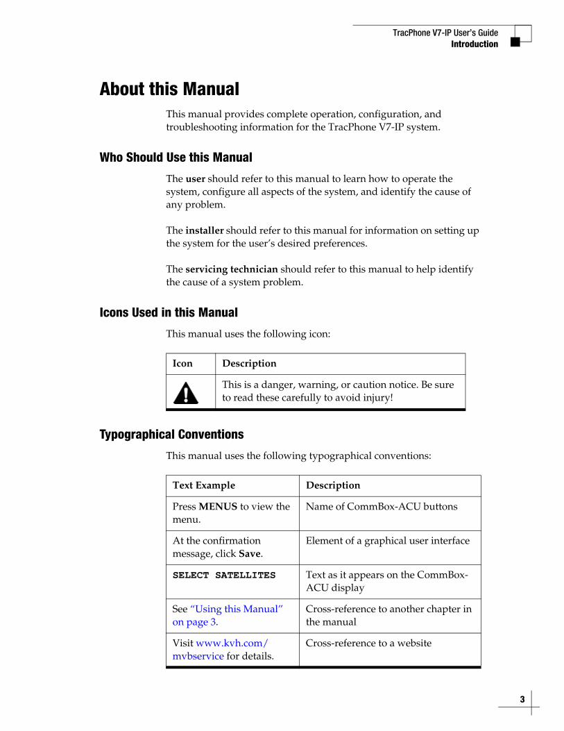
This manual uses the following icon:
Typographical Conventions
This manual uses the following typographical conventions:
Icon Description
This is a danger, warning, or caution notice. Be sure to read these carefully to avoid injury!
Text Example Description
Press MENUS to view the menu.
Name of CommBox-ACU buttons
At the confirmation message, click Save.
Element of a graphical user interface
SELECT SATELLITES Text as it appears on the CommBox-ACU display
See “Using this Manual” on page 3.
Cross-reference to another chapter in the manual
Visit www.kvh.com/mvbservice for details.
Cross-reference to a website
3
TracPhone V7-IP User’s Guide
4
Introduction
Related Documentation
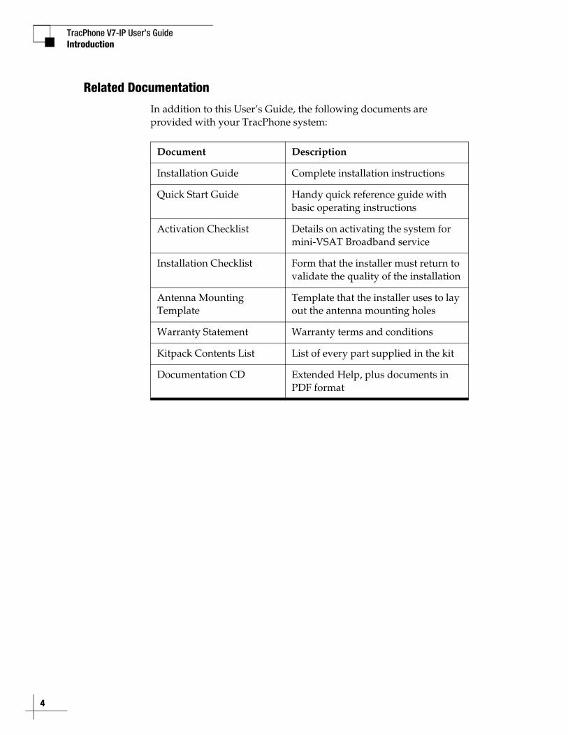
In addition to this User’s Guide, the following documents are provided with your TracPhone system:
Document Description
Installation Guide Complete installation instructions
Quick Start Guide Handy quick reference guide with basic operating instructions
Activation Checklist Details on activating the system for mini-VSAT Broadband service
Installation Checklist Form that the installer must return to validate the quality of the installation
Antenna Mounting Template
Template that the installer uses to lay out the antenna mounting holes
Warranty Statement Warranty terms and conditions
Kitpack Contents List List of every part supplied in the kit
Documentation CD Extended Help, plus documents in PDF format

TracPhone V7-IP User’s GuideIntroduction
Important Safety InformationFor your own safety, and for the safety of your passengers and/or crew, be sure to read the following important notices.
WARNING
Risk of Electric ShockPotentially lethal voltages are present within the CommBox-ACU and the modem. To avoid electric shock, do not open the chassis enclosures of the belowdecks equipment. They contain no user-serviceable parts, and opening the enclosure(s) will void the product’s warranty.
WARNING
Risk of Electric ShockFailure to ground the TracPhone system properly to ship’s ground will cause an unsafe floating ground condition, risking potentially lethal electric shock. Refer to the Installation Guide for details on the proper grounding of the equipment.
CAUTION
RF Radiation HazardThe antenna transmits up to 4 watts of radio frequency (RF) energy that is potentially harmful. Whenever the system is powered on, make sure everyone stays more than 36 feet (11 m) away from the antenna. No hazard exists directly below the antenna.
5
TracPhone V7-IP User’s Guide
6
Introduction
RF Radiation Hazard Area
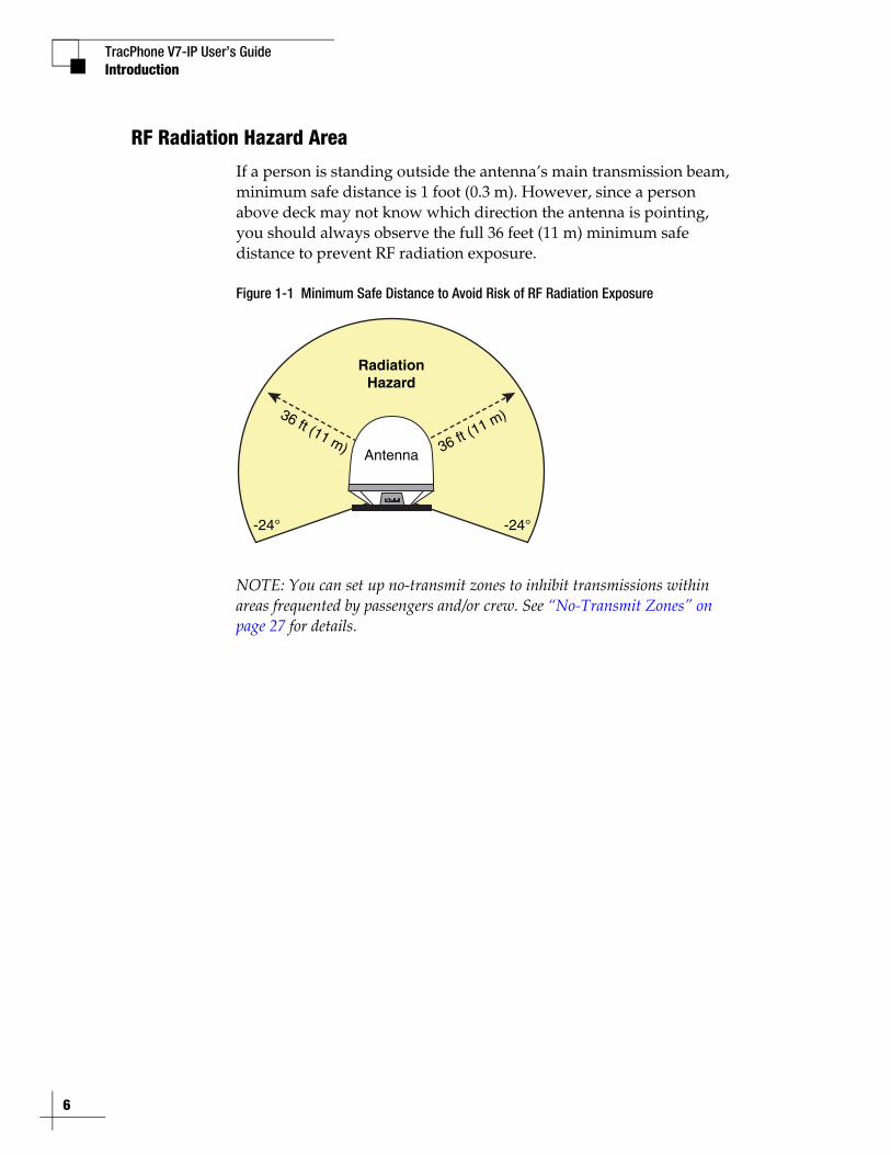
If a person is standing outside the antenna’s main transmission beam, minimum safe distance is 1 foot (0.3 m). However, since a person above deck may not know which direction the antenna is pointing, you should always observe the full 36 feet (11 m) minimum safe distance to prevent RF radiation exposure.
Figure 1-1 Minimum Safe Distance to Avoid Risk of RF Radiation Exposure
NOTE: You can set up no-transmit zones to inhibit transmissions within areas frequented by passengers and/or crew. See “No-Transmit Zones” on page 27 for details.
RadiationHazard
Antenna 36 ft (11 m)36 ft (11 m)
-24°-24°
TracPhone V7-IP User’s GuideIntroduction
System OverviewYour TracPhone V7-IP is a complete mini-VSAT Broadband communications system for mariners on the move. Using cutting-edge CRMA and spread spectrum technologies, the TracPhone V7-IP delivers a seamless and consistent Internet experience. And it all comes with an antenna that is smaller and lighter than traditional VSAT antennas.
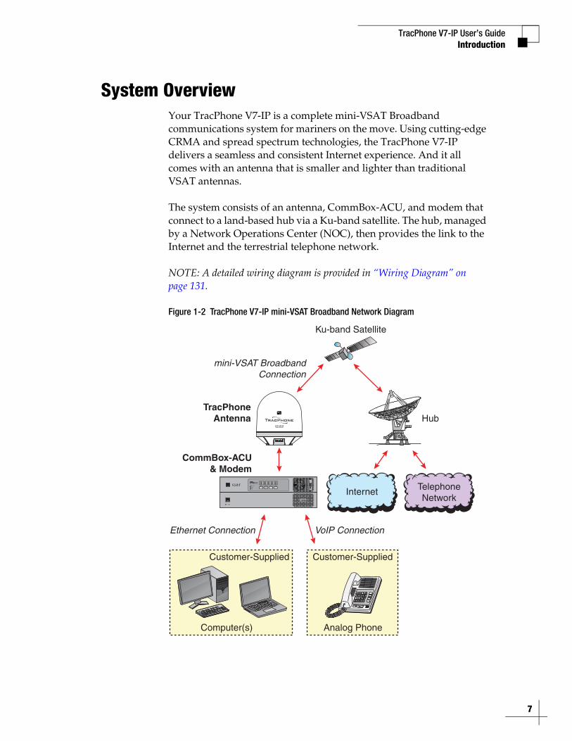
The system consists of an antenna, CommBox-ACU, and modem that connect to a land-based hub via a Ku-band satellite. The hub, managed by a Network Operations Center (NOC), then provides the link to the Internet and the terrestrial telephone network.
NOTE: A detailed wiring diagram is provided in “Wiring Diagram” on page 131.
Figure 1-2 TracPhone V7-IP mini-VSAT Broadband Network Diagram
HubTracPhone
Antenna
Ku-band Satellite
mini-VSAT BroadbandConnection
CommBox-ACU& Modem
VoIP ConnectionEthernet Connection
Internet TelephoneNetwork
Customer-Supplied
Computer(s)
Customer-Supplied
Analog Phone
STATUS
7

TracPhone V7-IP User’s Guide
8
Introduction
System Components
The TracPhone V7-IP system includes the following components:
Antenna UnitThe antenna unit provides the satellite link between the onboard modem and the land-based hub. Using its integrated GPS, advanced reflector technology, and gyro stabilization, the antenna automatically locates and tracks the correct satellite, even while your vessel is on the move. In addition, the antenna’s three-axis range of motion allows it to track the satellite at high elevations, even directly overhead.
Figure 1-3 Antenna Unit
CommBox-ACUThe CommBox-ACU links together all system components, including the antenna, the modem, and your onboard computers and phones. Its built-in router and wireless access point (WAP) transfer all data traffic between the modem and your onboard local area network (LAN). Its easy-to-use web interface and front panel LCD allow you to operate and configure all aspects of the system.
Figure 1-4 CommBox-ACU
ModemThe modem is the transceiver and “brain” of the system. It processes all incoming and outgoing data traffic between the antenna and the onboard LAN using its proprietary spread spectrum technologies.
Figure 1-5 Modem
TracPhone V7-IP User’s GuideIntroduction
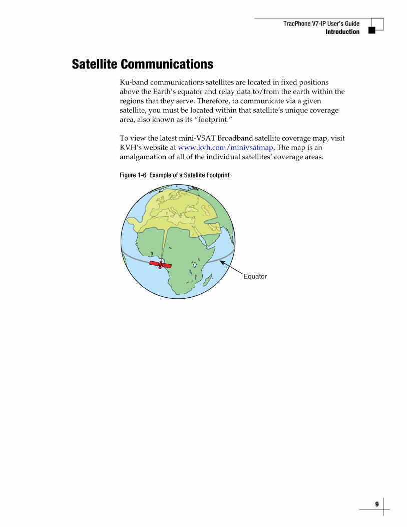
Satellite CommunicationsKu-band communications satellites are located in fixed positions above the Earth’s equator and relay data to/from the earth within the regions that they serve. Therefore, to communicate via a given satellite, you must be located within that satellite’s unique coverage area, also known as its “footprint.”
To view the latest mini-VSAT Broadband satellite coverage map, visit KVH’s website at www.kvh.com/minivsatmap. The map is an amalgamation of all of the individual satellites’ coverage areas.
Figure 1-6 Example of a Satellite Footprint
Equator
9
TracPhone V7-IP User’s Guide
10
Introduction
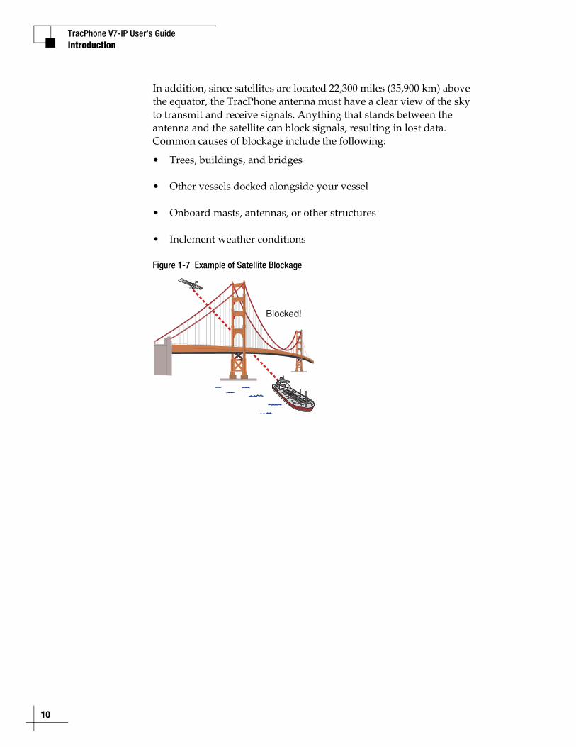
In addition, since satellites are located 22,300 miles (35,900 km) above the equator, the TracPhone antenna must have a clear view of the sky to transmit and receive signals. Anything that stands between the antenna and the satellite can block signals, resulting in lost data. Common causes of blockage include the following:
• Trees, buildings, and bridges
• Other vessels docked alongside your vessel
• Onboard masts, antennas, or other structures
• Inclement weather conditions
Figure 1-7 Example of Satellite Blockage
Blocked!
TracPhone V7-IP User’s Guide
11
Getting Started
2. Getting StartedThis section explains how to activate the TracPhone system for mini-VSAT Broadband service. It also explains how to turn on the system for the first time and how to interpret the system’s startup screens. Then it introduces the TracPhone V7-IP web interface, detailing how to access the Home page and the Help documentation.
ContentsService Activation............................................................ 13
Turning On the System.................................................... 15
System Startup................................................................ 16
Accessing the Web Interface........................................... 17
Understanding the Home Page........................................ 18
Viewing the Help (User Documentation) .......................... 19
TracPhone V7-IP User’s GuideGetting Started
Service ActivationBefore you can start using the TracPhone system, you need to activate it for mini-VSAT Broadband service. To activate, fill out and submit the following forms:
• mini-VSAT Broadband Service Activation FormComplete the leisure or commercial form, as appropriate
• End User AgreementRead and initial each page in the bottom right-hand corner
• Airtime Account Authorized Representative FormComplete, if applicable
All forms are available in PDF format at www.kvh.com/mvbservice.
NOTE: You will need to enter equipment ID numbers on the activation form. You can find these numbers on the Support page of the TracPhone V7-IP web interface or in the System Info LCD menu on the CommBox-ACU’s front panel. See “Equipment ID Numbers” on page 106.
Fax or e-mail the completed forms to KVH:
North/South America, Australia:Fax: +1 401 851-3823E-mail: [email protected]
Europe, Middle East, Asia, Africa:Fax: +45 45 160 181E-mail: [email protected]
Once KVH processes these forms, activates your account, and registers your product, you will receive an e-mail with the details of your new service, including your vessel’s phone numbers.
13
TracPhone V7-IP User’s Guide
14
Getting Started
Contacting KVH’s Satellite Airtime & Product Activation Department
If you have any questions, or would like to make a change to your account, please contact KVH’s Satellite Airtime & Product Activation Department:
North/South America, Australia:Mon.-Fri., 8:30 am-5 pm ETToll-free: +1 866 399-8509 (U.S. only)Phone: +1 401 847-3327E-mail: [email protected]
Europe, Middle East, Asia, Africa:Mon.-Thu., 8 am-4:30 pm CETFri., 8 am-2 pm CETPhone: +45 45 160 180E-mail: [email protected]
TracPhone V7-IP User’s GuideGetting Started
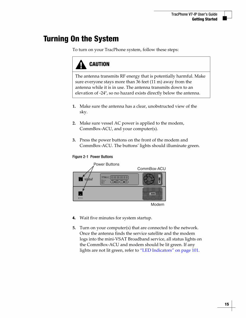
Turning On the SystemTo turn on your TracPhone system, follow these steps:
1. Make sure the antenna has a clear, unobstructed view of the sky.
2. Make sure vessel AC power is applied to the modem, CommBox-ACU, and your computer(s).
3. Press the power buttons on the front of the modem and CommBox-ACU. The buttons’ lights should illuminate green.
Figure 2-1 Power Buttons
4. Wait five minutes for system startup.
5. Turn on your computer(s) that are connected to the network. Once the antenna finds the service satellite and the modem logs into the mini-VSAT Broadband service, all status lights on the CommBox-ACU and modem should be lit green. If any lights are not lit green, refer to “LED Indicators” on page 101.
CAUTION
The antenna transmits RF energy that is potentially harmful. Make sure everyone stays more than 36 feet (11 m) away from the antenna while it is in use. The antenna transmits down to an elevation of -24º, so no hazard exists directly below the antenna.
Power Buttons
STATUS
CommBox-ACU
Modem
15
TracPhone V7-IP User’s Guide
16
Getting Started
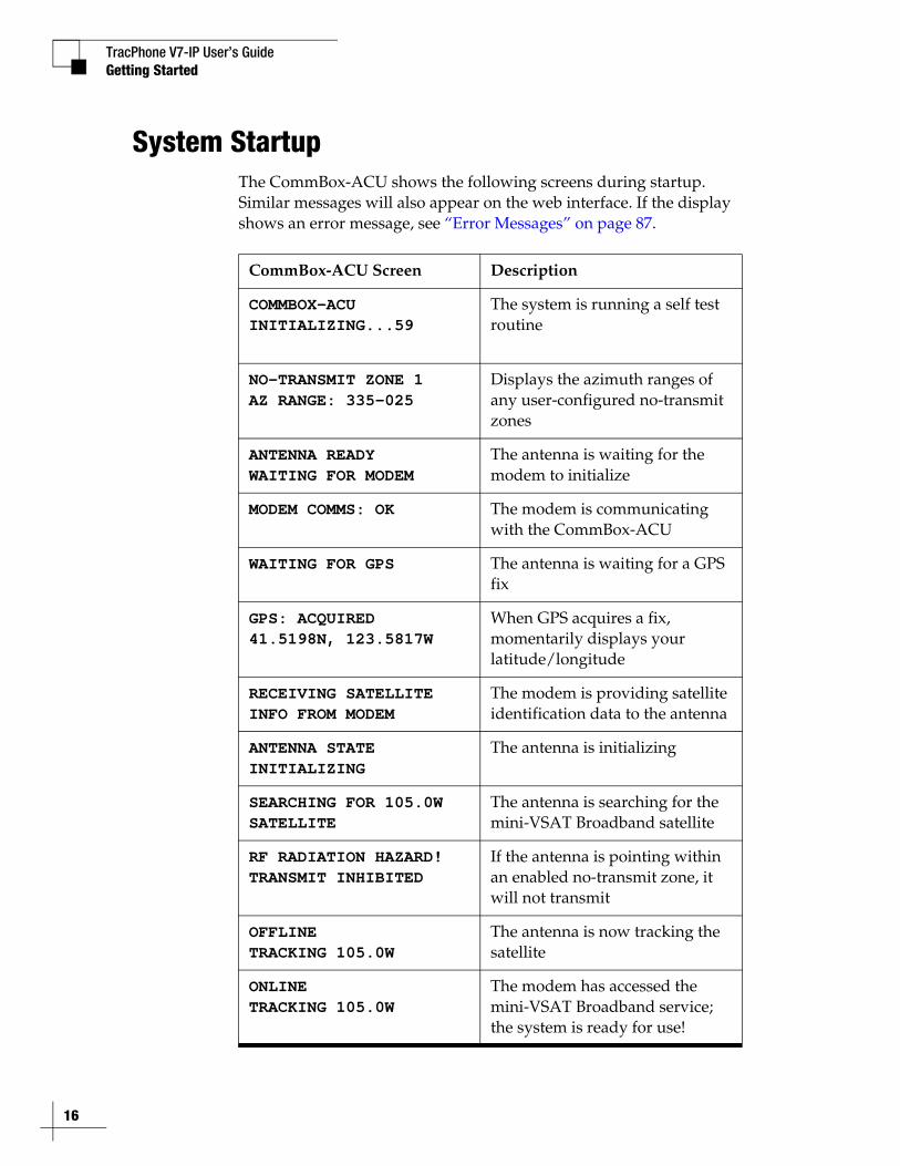
System StartupThe CommBox-ACU shows the following screens during startup. Similar messages will also appear on the web interface. If the display shows an error message, see “Error Messages” on page 87.
CommBox-ACU Screen Description
COMMBOX-ACUINITIALIZING...59
The system is running a self test routine
NO-TRANSMIT ZONE 1AZ RANGE: 335-025
Displays the azimuth ranges of any user-configured no-transmit zones
ANTENNA READYWAITING FOR MODEM
The antenna is waiting for the modem to initialize
MODEM COMMS: OK The modem is communicating with the CommBox-ACU
WAITING FOR GPS The antenna is waiting for a GPS fix
GPS: ACQUIRED41.5198N, 123.5817W
When GPS acquires a fix, momentarily displays your latitude/longitude
RECEIVING SATELLITEINFO FROM MODEM
The modem is providing satellite identification data to the antenna
ANTENNA STATEINITIALIZING
The antenna is initializing
SEARCHING FOR 105.0WSATELLITE
The antenna is searching for the mini-VSAT Broadband satellite
RF RADIATION HAZARD!TRANSMIT INHIBITED
If the antenna is pointing within an enabled no-transmit zone, it will not transmit
OFFLINETRACKING 105.0W
The antenna is now tracking the satellite
ONLINETRACKING 105.0W
The modem has accessed the mini-VSAT Broadband service; the system is ready for use!
TracPhone V7-IP User’s GuideGetting Started
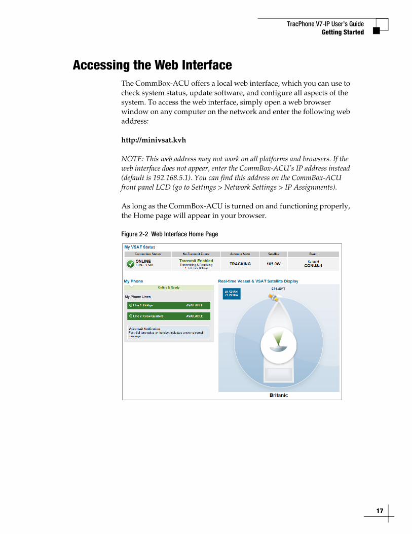
Accessing the Web InterfaceThe CommBox-ACU offers a local web interface, which you can use to check system status, update software, and configure all aspects of the system. To access the web interface, simply open a web browser window on any computer on the network and enter the following web address:
http://minivsat.kvh
NOTE: This web address may not work on all platforms and browsers. If the web interface does not appear, enter the CommBox-ACU’s IP address instead (default is 192.168.5.1). You can find this address on the CommBox-ACU front panel LCD (go to Settings > Network Settings > IP Assignments).
As long as the CommBox-ACU is turned on and functioning properly, the Home page will appear in your browser.
Figure 2-2 Web Interface Home Page
17
TracPhone V7-IP User’s Guide
18
Getting Started
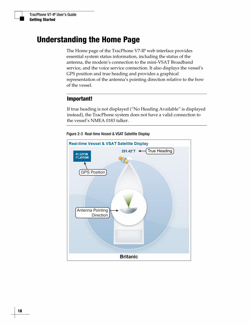
Understanding the Home PageThe Home page of the TracPhone V7-IP web interface provides essential system status information, including the status of the antenna, the modem’s connection to the mini-VSAT Broadband service, and the voice service connection. It also displays the vessel’s GPS position and true heading and provides a graphical representation of the antenna’s pointing direction relative to the bow of the vessel.
Figure 2-3 Real-time Vessel & VSAT Satellite Display
Important!
If true heading is not displayed (“No Heading Available” is displayed instead), the TracPhone system does not have a valid connection to the vessel’s NMEA 0183 talker.
True Heading
GPS Position
Antenna PointingDirection
TracPhone V7-IP User’s GuideGetting Started
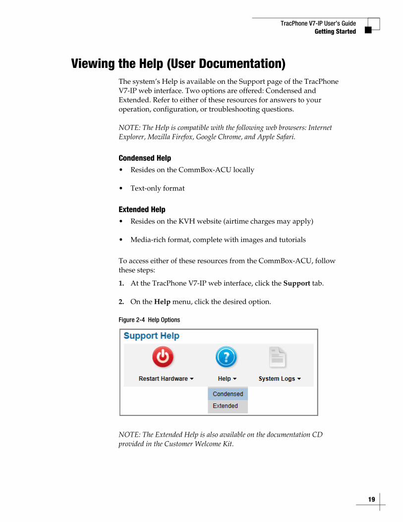
Viewing the Help (User Documentation)The system’s Help is available on the Support page of the TracPhone V7-IP web interface. Two options are offered: Condensed and Extended. Refer to either of these resources for answers to your operation, configuration, or troubleshooting questions.
NOTE: The Help is compatible with the following web browsers: Internet Explorer, Mozilla Firefox, Google Chrome, and Apple Safari.
Condensed Help• Resides on the CommBox-ACU locally
• Text-only format
Extended Help• Resides on the KVH website (airtime charges may apply)
• Media-rich format, complete with images and tutorials
To access either of these resources from the CommBox-ACU, follow these steps:
1. At the TracPhone V7-IP web interface, click the Support tab.
2. On the Help menu, click the desired option.
Figure 2-4 Help Options
NOTE: The Extended Help is also available on the documentation CD provided in the Customer Welcome Kit.
19

TracPhone V7-IP User’s Guide
21
Interface Preferences
3. Interface PreferencesThis section explains how to customize the TracPhone V7-IP web interface by entering the names of the vessel and phone lines. It also explains how to change the Administrator password and adjust the brightness of the CommBox-ACU’s front panel LCD.
ContentsChanging the Administrator Password ............................ 23
Entering the Vessel Name ............................................... 24
Assigning Phone Line Names .......................................... 25
Adjusting the LCD Brightness .......................................... 26
TracPhone V7-IP User’s GuideInterface Preferences
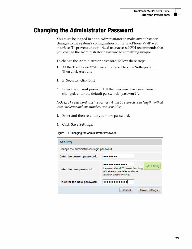
Changing the Administrator PasswordYou must be logged in as an Administrator to make any substantial changes to the system’s configuration on the TracPhone V7-IP web interface. To prevent unauthorized user access, KVH recommends that you change the Administrator password to something unique.
To change the Administrator password, follow these steps:
1. At the TracPhone V7-IP web interface, click the Settings tab. Then click Account.
2. In Security, click Edit.
3. Enter the current password. If the password has never been changed, enter the default password: “password”.
NOTE: The password must be between 4 and 20 characters in length, with at least one letter and one number, case-sensitive.
4. Enter and then re-enter your new password.
5. Click Save Settings.
Figure 3-1 Changing the Administrator Password
23
TracPhone V7-IP User’s Guide
24
Interface Preferences
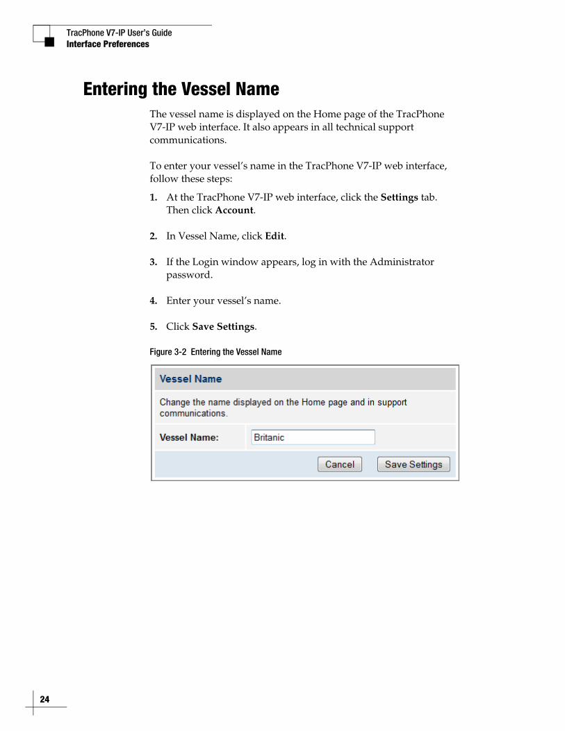
Entering the Vessel NameThe vessel name is displayed on the Home page of the TracPhone V7-IP web interface. It also appears in all technical support communications.
To enter your vessel’s name in the TracPhone V7-IP web interface, follow these steps:
1. At the TracPhone V7-IP web interface, click the Settings tab. Then click Account.
2. In Vessel Name, click Edit.
3. If the Login window appears, log in with the Administrator password.
4. Enter your vessel’s name.
5. Click Save Settings.
Figure 3-2 Entering the Vessel Name
TracPhone V7-IP User’s GuideInterface Preferences
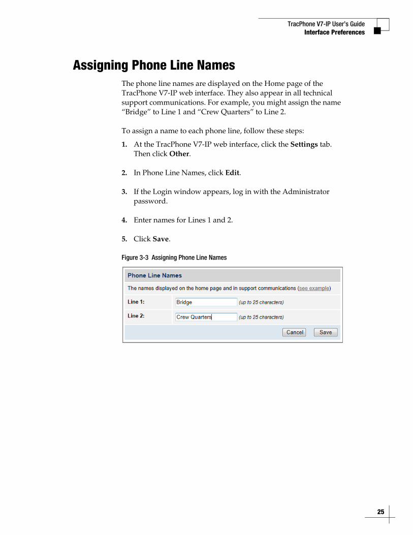
Assigning Phone Line NamesThe phone line names are displayed on the Home page of the TracPhone V7-IP web interface. They also appear in all technical support communications. For example, you might assign the name “Bridge” to Line 1 and “Crew Quarters” to Line 2.
To assign a name to each phone line, follow these steps:
1. At the TracPhone V7-IP web interface, click the Settings tab. Then click Other.
2. In Phone Line Names, click Edit.
3. If the Login window appears, log in with the Administrator password.
4. Enter names for Lines 1 and 2.
5. Click Save.
Figure 3-3 Assigning Phone Line Names
25
TracPhone V7-IP User’s Guide
26
Interface Preferences
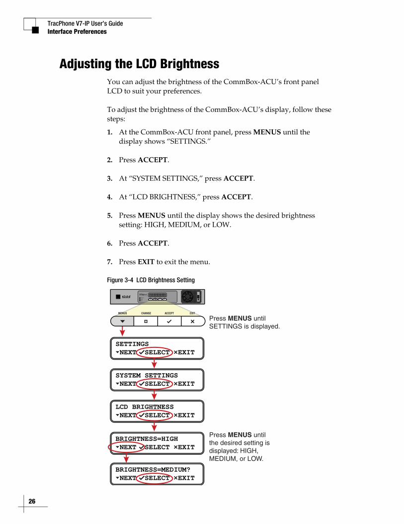
Adjusting the LCD BrightnessYou can adjust the brightness of the CommBox-ACU’s front panel LCD to suit your preferences.
To adjust the brightness of the CommBox-ACU’s display, follow these steps:
1. At the CommBox-ACU front panel, press MENUS until the display shows “SETTINGS.”
2. Press ACCEPT.
3. At “SYSTEM SETTINGS,” press ACCEPT.
4. At “LCD BRIGHTNESS,” press ACCEPT.
5. Press MENUS until the display shows the desired brightness setting: HIGH, MEDIUM, or LOW.
6. Press ACCEPT.
7. Press EXIT to exit the menu.
Figure 3-4 LCD Brightness Setting
SETTINGS NEXT SELECT EXIT
SYSTEM SETTINGS NEXT SELECT EXIT
LCD BRIGHTNESS NEXT SELECT EXIT
BRIGHTNESS=HIGH NEXT SELECT EXIT
BRIGHTNESS=MEDIUM? NEXT SELECT EXIT
Press MENUS until the desired setting isdisplayed: HIGH,MEDIUM, or LOW.
Press MENUS until SETTINGS is displayed.
TracPhone V7-IP User’s Guide
27
No-Transmit Zones
4. No-Transmit ZonesThis section explains how to view, configure, temporarily disable, and clear no-transmit zones, which prohibit the antenna from transmitting within a certain azimuth range.
ContentsNo-Transmit Zones Overview .......................................... 29
Status of No-Transmit Zones........................................... 30
Establishing No-Transmit Zones...................................... 31
Disabling No-Transmit Zones .......................................... 33
Clearing No-Transmit Zones............................................ 34
TracPhone V7-IP User’s GuideNo-Transmit Zones
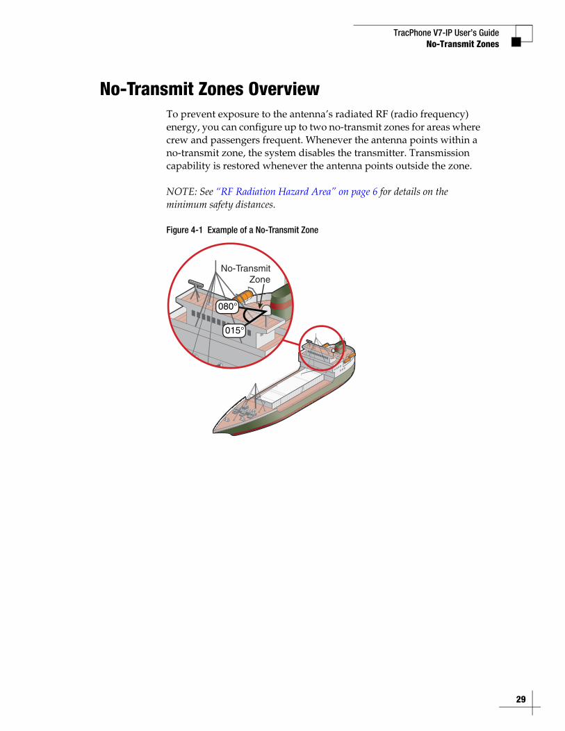
No-Transmit Zones OverviewTo prevent exposure to the antenna’s radiated RF (radio frequency) energy, you can configure up to two no-transmit zones for areas where crew and passengers frequent. Whenever the antenna points within a no-transmit zone, the system disables the transmitter. Transmission capability is restored whenever the antenna points outside the zone.
NOTE: See “RF Radiation Hazard Area” on page 6 for details on the minimum safety distances.
Figure 4-1 Example of a No-Transmit Zone
No-TransmitZone
29
TracPhone V7-IP User’s Guide
30
No-Transmit Zones
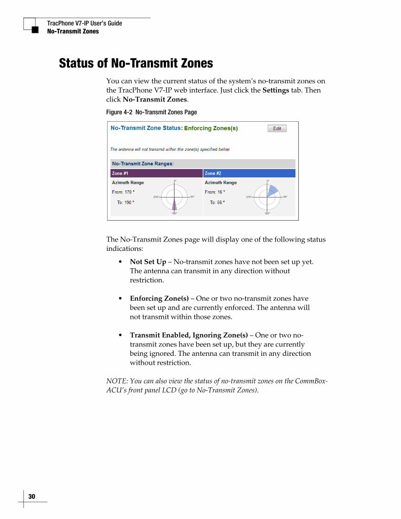
Status of No-Transmit ZonesYou can view the current status of the system’s no-transmit zones on the TracPhone V7-IP web interface. Just click the Settings tab. Then click No-Transmit Zones.
Figure 4-2 No-Transmit Zones Page
The No-Transmit Zones page will display one of the following status indications:
• Not Set Up – No-transmit zones have not been set up yet. The antenna can transmit in any direction without restriction.
• Enforcing Zone(s) – One or two no-transmit zones have been set up and are currently enforced. The antenna will not transmit within those zones.
• Transmit Enabled, Ignoring Zone(s) – One or two no-transmit zones have been set up, but they are currently being ignored. The antenna can transmit in any direction without restriction.
NOTE: You can also view the status of no-transmit zones on the CommBox-ACU’s front panel LCD (go to No-Transmit Zones).

TracPhone V7-IP User’s GuideNo-Transmit Zones
Establishing No-Transmit ZonesTo configure a no-transmit zone, follow these steps:
1. Identify the necessary azimuth range for the zone (see “Identify the Azimuth Range”).
2. At the TracPhone V7-IP web interface, configure a no-transmit zone for that azimuth range (see “Configure the No-Transmit Zone(s) at the Web Interface” on page 32).
Identify the Azimuth RangeFirst, you need to determine the necessary azimuth range for the no-transmit zone(s). You will need to enter, in clockwise order, the beginning and ending azimuths that define the outer boundaries of the zone, relative to the antenna’s forward arrow, which should be pointing toward the bow.
NOTE: Each no-transmit zone must span at least 5º. Therefore, be sure to set beginning and ending azimuths at least 5º apart.
Figure 4-3 Beginning and Ending Azimuths Defining a No-Transmit Zone (Example)
Antenna
000
180
090270
135225
315 Forward
015
080
No-Transmit Zone(Example)
Beginning AzimuthFROM
Ending AzimuthTO
31
TracPhone V7-IP User’s Guide
32
No-Transmit Zones
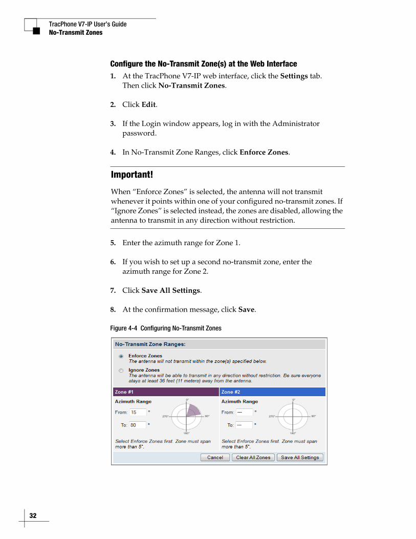
Configure the No-Transmit Zone(s) at the Web Interface1. At the TracPhone V7-IP web interface, click the Settings tab.
Then click No-Transmit Zones.
2. Click Edit.
3. If the Login window appears, log in with the Administrator password.
4. In No-Transmit Zone Ranges, click Enforce Zones.
5. Enter the azimuth range for Zone 1.
6. If you wish to set up a second no-transmit zone, enter the azimuth range for Zone 2.
7. Click Save All Settings.
8. At the confirmation message, click Save.
Figure 4-4 Configuring No-Transmit Zones
Important!
When “Enforce Zones” is selected, the antenna will not transmit whenever it points within one of your configured no-transmit zones. If “Ignore Zones” is selected instead, the zones are disabled, allowing the antenna to transmit in any direction without restriction.
TracPhone V7-IP User’s Guide
33
No-Transmit Zones
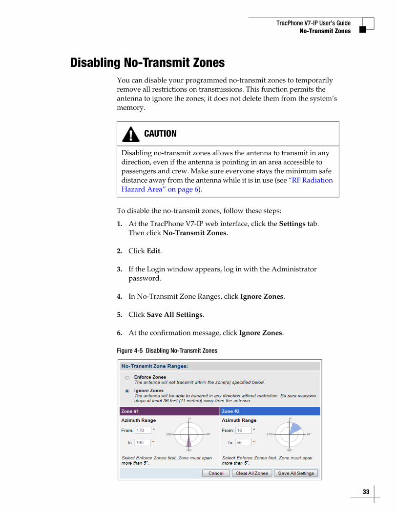
Disabling No-Transmit ZonesYou can disable your programmed no-transmit zones to temporarily remove all restrictions on transmissions. This function permits the antenna to ignore the zones; it does not delete them from the system’s memory.
To disable the no-transmit zones, follow these steps:
1. At the TracPhone V7-IP web interface, click the Settings tab. Then click No-Transmit Zones.
2. Click Edit.
3. If the Login window appears, log in with the Administrator password.
4. In No-Transmit Zone Ranges, click Ignore Zones.
5. Click Save All Settings.
6. At the confirmation message, click Ignore Zones.
Figure 4-5 Disabling No-Transmit Zones
CAUTION
Disabling no-transmit zones allows the antenna to transmit in any direction, even if the antenna is pointing in an area accessible to passengers and crew. Make sure everyone stays the minimum safe distance away from the antenna while it is in use (see “RF Radiation Hazard Area” on page 6).
TracPhone V7-IP User’s Guide
34
No-Transmit Zones
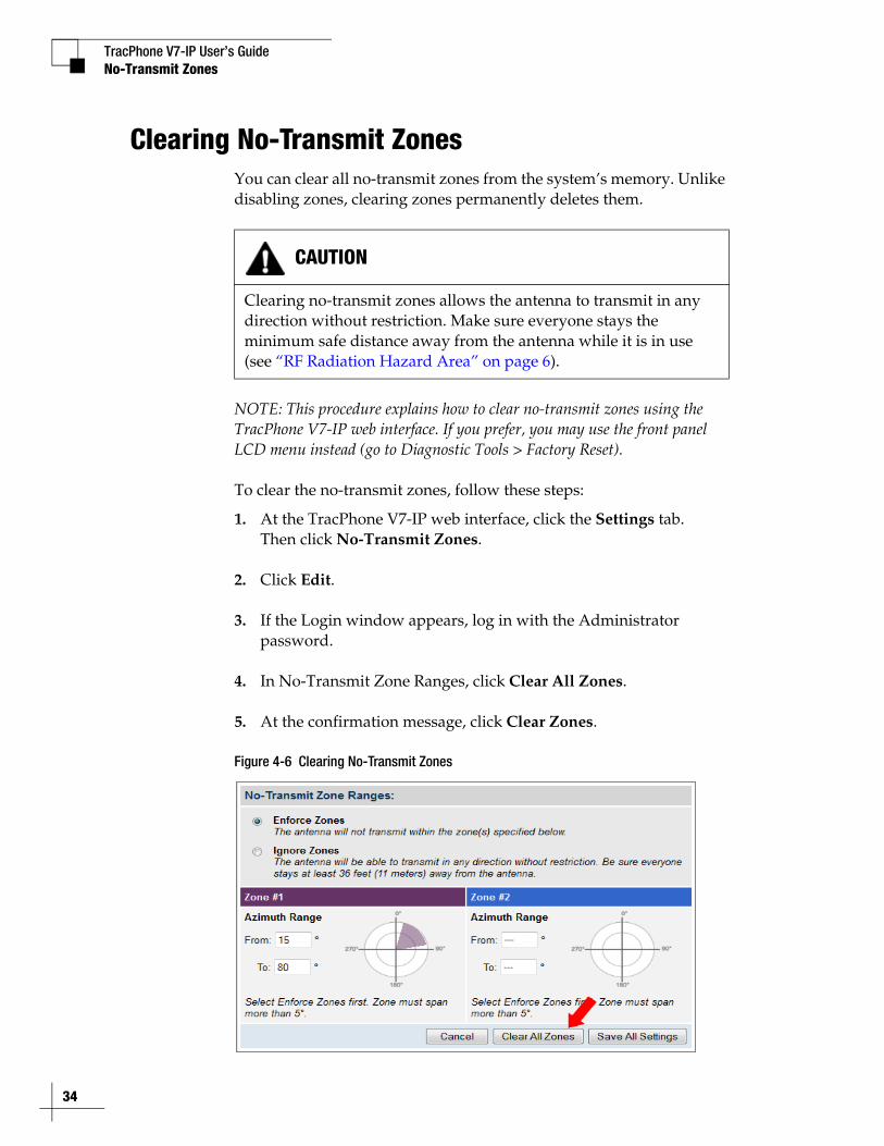
Clearing No-Transmit ZonesYou can clear all no-transmit zones from the system’s memory. Unlike disabling zones, clearing zones permanently deletes them.
NOTE: This procedure explains how to clear no-transmit zones using the TracPhone V7-IP web interface. If you prefer, you may use the front panel LCD menu instead (go to Diagnostic Tools > Factory Reset).
To clear the no-transmit zones, follow these steps:
1. At the TracPhone V7-IP web interface, click the Settings tab. Then click No-Transmit Zones.
2. Click Edit.
3. If the Login window appears, log in with the Administrator password.
4. In No-Transmit Zone Ranges, click Clear All Zones.
5. At the confirmation message, click Clear Zones.
Figure 4-6 Clearing No-Transmit Zones
CAUTION
Clearing no-transmit zones allows the antenna to transmit in any direction without restriction. Make sure everyone stays the minimum safe distance away from the antenna while it is in use (see “RF Radiation Hazard Area” on page 6).

TracPhone V7-IP User’s Guide
35
Voice Connections
5. Voice ConnectionsThis section covers everything you need to know about the enhanced voice service. It explains how to place calls, add additional phone lines and virtual numbers, check VoiceMail, send a fax, and access your voice account online.
ContentsVoice Service Overview ................................................... 37
Making a Ship-to-Shore Call ........................................... 38
Making a Shore-to-Ship Call ........................................... 40
Adding Phone Lines ......................................................... 41
Virtual Numbers............................................................... 44
VoiceMail ......................................................................... 45
Faxing.............................................................................. 47
Accessing Your Voice Account ........................................ 49
TracPhone V7-IP User’s Guide
37
Voice Connections
Voice Service OverviewKVH’s enhanced voice service – Voice over IP (VoIP) optimized for satellite communications – allows you to make and receive phone calls via the TracPhone system and the mini-VSAT Broadband service. Voice traffic is given priority on the network over standard Internet data to ensure the highest quality voice connections at all times.
How the Voice Service Works
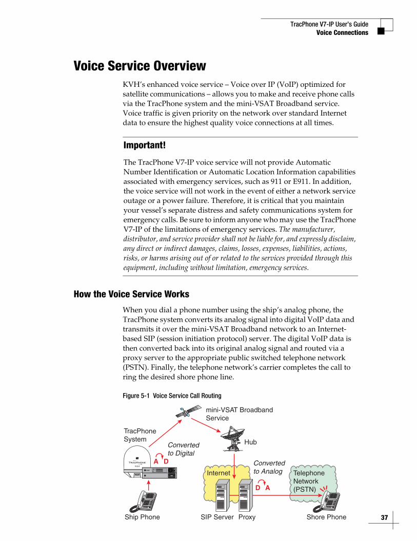
When you dial a phone number using the ship’s analog phone, the TracPhone system converts its analog signal into digital VoIP data and transmits it over the mini-VSAT Broadband network to an Internet-based SIP (session initiation protocol) server. The digital VoIP data is then converted back into its original analog signal and routed via a proxy server to the appropriate public switched telephone network (PSTN). Finally, the telephone network’s carrier completes the call to ring the desired shore phone line.
Figure 5-1 Voice Service Call Routing
Important!
The TracPhone V7-IP voice service will not provide Automatic Number Identification or Automatic Location Information capabilities associated with emergency services, such as 911 or E911. In addition, the voice service will not work in the event of either a network service outage or a power failure. Therefore, it is critical that you maintain your vessel’s separate distress and safety communications system for emergency calls. Be sure to inform anyone who may use the TracPhone V7-IP of the limitations of emergency services. The manufacturer, distributor, and service provider shall not be liable for, and expressly disclaim, any direct or indirect damages, claims, losses, expenses, liabilities, actions, risks, or harms arising out of or related to the services provided through this equipment, including without limitation, emergency services.
Convertedto Digital
mini-VSAT Broadband Service
Internet
SIP Server Proxy
TelephoneNetwork(PSTN)
Shore Phone
A D
Hub
Convertedto Analog
D A
STATUS
Ship Phone
TracPhoneSystem
TracPhone V7-IP User’s Guide
38
Voice Connections
Making a Ship-to-Shore CallTo place a call from the vessel, follow these steps:
1. Make sure the TracPhone system is online.
2. Pick up the handset on any phone connected to the CommBox-ACU. You should hear a dial tone. If you don’t, check the phone line status on the web interface’s Home tab.
3. Dial the phone number you wish to call. The dialing sequence you use depends on the vessel’s Line 1 phone number.
Dialing a Number Outside the Country Assigned to Line 1Dial the number as an international call:<International prefix, as originating from your Line 1 country> + <country code> + <area/city code> + <local phone number>
Dialing a Number Within the Country Assigned to Line 1Dial the number as an in-country call:<area/city code> + <local phone number>
Dialing a Number Within the Country & Area Code Assigned to Line 1Dial the number as a local call:<local phone number>
NOTE: When you place a call, your voice travels to a satellite in space then back to Earth. This transit will cause a brief delay (approximately 1/2 second) in your conversation.
TracPhone V7-IP User’s GuideVoice Connections
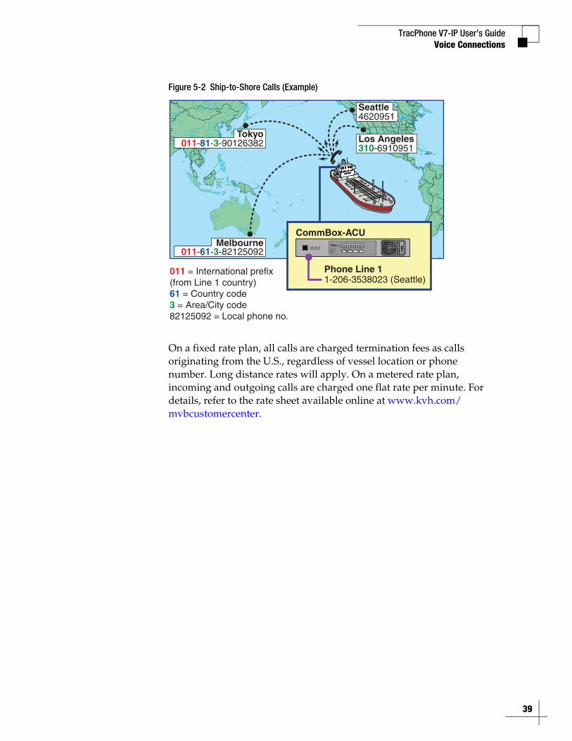
Figure 5-2 Ship-to-Shore Calls (Example)
On a fixed rate plan, all calls are charged termination fees as calls originating from the U.S., regardless of vessel location or phone number. Long distance rates will apply. On a metered rate plan, incoming and outgoing calls are charged one flat rate per minute. For details, refer to the rate sheet available online at www.kvh.com/mvbcustomercenter.
011 = International prefix(from Line 1 country)61 = Country code3 = Area/City code82125092 = Local phone no.
Tokyo011-81-3-90126382
Melbourne011-61-3-82125092
Los Angeles310-6910951
Seattle4620951
1-206-3538023 (Seattle)Phone Line 1
CommBox-ACU
39
TracPhone V7-IP User’s Guide
40
Voice Connections
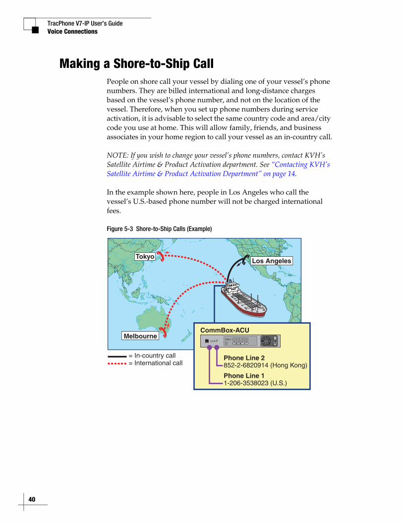
Making a Shore-to-Ship CallPeople on shore call your vessel by dialing one of your vessel’s phone numbers. They are billed international and long-distance charges based on the vessel’s phone number, and not on the location of the vessel. Therefore, when you set up phone numbers during service activation, it is advisable to select the same country code and area/city code you use at home. This will allow family, friends, and business associates in your home region to call your vessel as an in-country call.
NOTE: If you wish to change your vessel’s phone numbers, contact KVH’s Satellite Airtime & Product Activation department. See “Contacting KVH’s Satellite Airtime & Product Activation Department” on page 14.
In the example shown here, people in Los Angeles who call the vessel’s U.S.-based phone number will not be charged international fees.
Figure 5-3 Shore-to-Ship Calls (Example)
Melbourne
TokyoLos Angeles
= In-country call= International call
1-206-3538023 (U.S.)Phone Line 1
CommBox-ACU
852-2-6820914 (Hong Kong)Phone Line 2
TracPhone V7-IP User’s Guide
41
Voice Connections
Adding Phone LinesThe CommBox-ACU supports two phone lines, one for each “Voice Line” jack. As a result, the system supports two simultaneous voice calls. However, KVH offers the following optional accessories that add additional phone lines to support three or more simultaneous calls:
• Multimedia Terminal Adapter (MTA) (see “Additional MTA(s)” on page 42)
• Crew Calling Gateway (see “Crew Calling Gateway” on page 43)
NOTE: Only voice calls carried on phone lines 1 and 2 are prioritized over general data traffic.
TracPhone V7-IP User’s Guide
42
Voice Connections
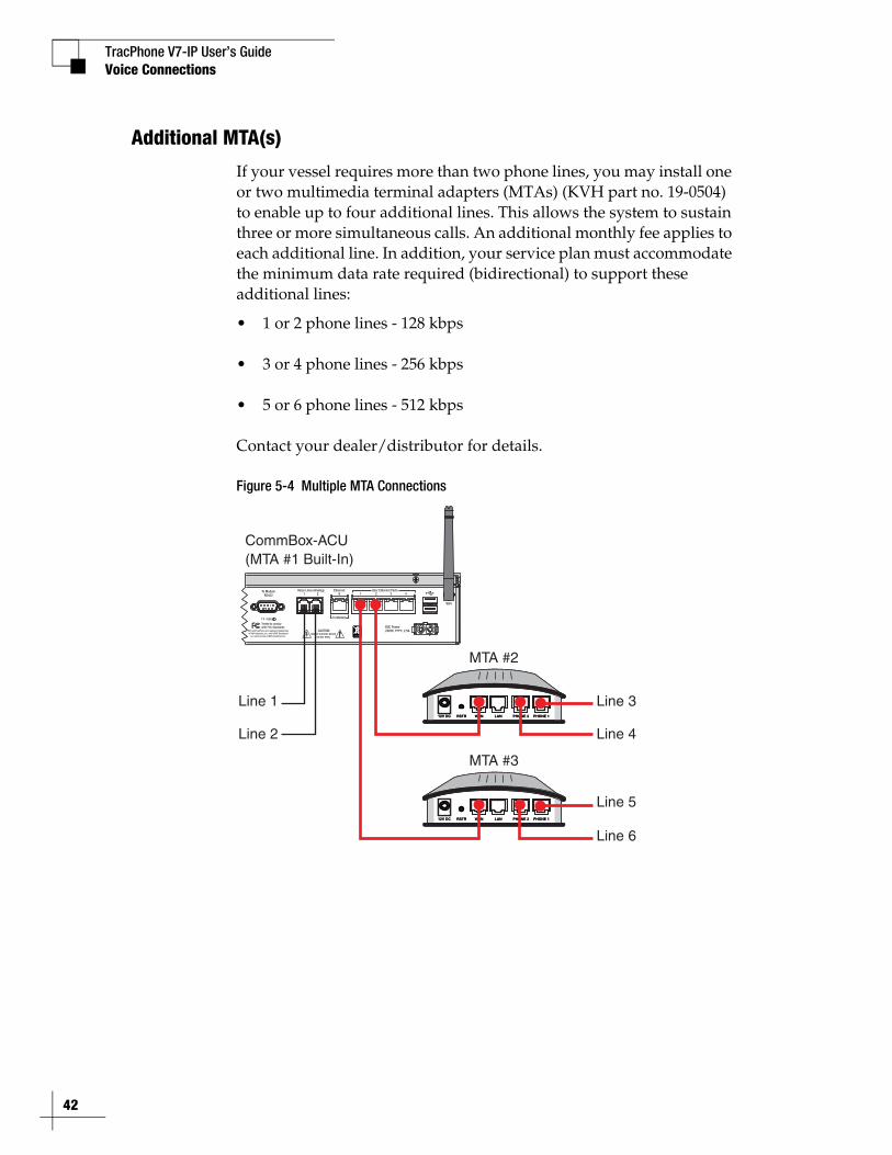
Additional MTA(s)
If your vessel requires more than two phone lines, you may install one or two multimedia terminal adapters (MTAs) (KVH part no. 19-0504) to enable up to four additional lines. This allows the system to sustain three or more simultaneous calls. An additional monthly fee applies to each additional line. In addition, your service plan must accommodate the minimum data rate required (bidirectional) to support these additional lines:
• 1 or 2 phone lines - 128 kbps
• 3 or 4 phone lines - 256 kbps
• 5 or 6 phone lines - 512 kbps
Contact your dealer/distributor for details.
Figure 5-4 Multiple MTA Connections
To ModemRS422 1 2 0
WiFi
1 2 3 4Voice Lines (Analog) User Ethernet PortsEthernet
To Modem
BUC Power24VDC , 2.5AKVH and TracPhone are registered trademarks
of KVH Industries, Inc.; mini-VSAT Broadband is a service mark of KVH Industries, Inc.
Tested to comply with FCC Standards
CAUTIONRISK OF ELECTRIC SHOCK
DO NOT OPEN
1000
CommBox-ACU
Line 1
Line 2
12V DC RSTR WAN LAN PHONE 2 PHONE 1
MTA #2
12V DC RSTR WAN LAN PHONE 2 PHONE 1
12V DC RSTR WAN LAN PHONE 2 PHONE 1
MTA #3
12V DC RSTR WAN LAN PHONE 2 PHONE 1
Line 6
Line 5
Line 3
Line 4
(MTA #1 Built-In)
TracPhone V7-IP User’s GuideVoice Connections
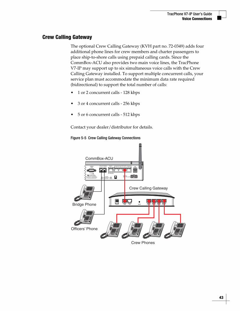
Crew Calling Gateway
The optional Crew Calling Gateway (KVH part no. 72-0349) adds four additional phone lines for crew members and charter passengers to place ship-to-shore calls using prepaid calling cards. Since the CommBox-ACU also provides two main voice lines, the TracPhone V7-IP may support up to six simultaneous voice calls with the Crew Calling Gateway installed. To support multiple concurrent calls, your service plan must accommodate the minimum data rate required (bidirectional) to support the total number of calls:
• 1 or 2 concurrent calls - 128 kbps
• 3 or 4 concurrent calls - 256 kbps
• 5 or 6 concurrent calls - 512 kbps
Contact your dealer/distributor for details.
Figure 5-5 Crew Calling Gateway Connections
Crew Calling Gateway
To ModemRS422 1 2 0
WiFi
1 2 3 4Voice Lines (Analog) User Ethernet PortsEthernet
To Modem
BUC Power24VDC , 2.5AKVH and TracPhone are registered trademarks
of KVH Industries, Inc.; mini-VSAT Broadband is a service mark of KVH Industries, Inc.
Tested to comply with FCC Standards
CAUTIONRISK OF ELECTRIC SHOCK
DO NOT OPEN
1000
CommBox-ACU
Bridge Phone
Officers’ Phone
12V DC RSTRWAN LAN PHONE 4 PHONE 3 PHONE 2 PHONE 1
Crew Phones
43
TracPhone V7-IP User’s Guide
44
Voice Connections
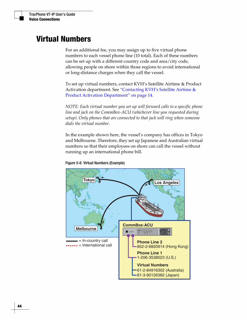
Virtual NumbersFor an additional fee, you may assign up to five virtual phone numbers to each vessel phone line (10 total). Each of these numbers can be set up with a different country code and area/city code, allowing people on shore within those regions to avoid international or long-distance charges when they call the vessel.
To set up virtual numbers, contact KVH’s Satellite Airtime & Product Activation department. See “Contacting KVH’s Satellite Airtime & Product Activation Department” on page 14.
NOTE: Each virtual number you set up will forward calls to a specific phone line and jack on the CommBox-ACU (whichever line you requested during setup). Only phones that are connected to that jack will ring when someone dials the virtual number.
In the example shown here, the vessel’s company has offices in Tokyo and Melbourne. Therefore, they set up Japanese and Australian virtual numbers so that their employees on shore can call the vessel without running up an international phone bill.
Figure 5-6 Virtual Numbers (Example)
Melbourne
TokyoLos Angeles
= In-country call= International call
1-206-3538023 (U.S.)Phone Line 1
CommBox-ACU
852-2-6820914 (Hong Kong)Phone Line 2
61-2-84916302 (Australia)81-3-90126382 (Japan)
Virtual Numbers
TracPhone V7-IP User’s GuideVoice Connections
VoiceMailKVH’s enhanced voice service offers a similar suite of features as you might find with any landline telephone service. One of these features is VoiceMail.
With VoiceMail, people who call the vessel may record a message if you are unable to answer the call or the line is busy. You can then play back and listen to your messages anytime (24/7) from anywhere, even if you are not currently onboard the vessel.
Recording a VoiceMail Personal Greeting
To record your VoiceMail personal greeting, follow these steps:
1. Pick up the handset on any phone connected to the CommBox-ACU. You should hear a dial tone.
2. Dial 123# to connect to the VoiceMail system.
3. Press 2 to access your mailbox.
4. Press 1 to access your personal greeting.
5. Press 2 to change your greeting. You will be prompted to record your greeting.
6. Press 1 to listen to your personal greeting.
7. When you are satisfied with your greeting, press 3 to accept and activate your greeting. You will hear the message “Your personal greeting has been activated.”
Listening to Your VoiceMail Messages
If you hear a fast dial tone pulse in the phone’s handset, you have new VoiceMail messages. To listen to your VoiceMail messages, follow these steps:
1. Dial 123# to connect to the VoiceMail system.
2. Press 1 to listen to your messages.
3. Follow the spoken instructions to listen to, save, and/or delete your messages.
45
TracPhone V7-IP User’s Guide
46
Voice Connections
Listening to Your Messages on ShoreYou still have access to your VoiceMail messages when you disembark the vessel. Choose one of the following options:
• Use a computer: Go to your voice account web page (see “Accessing Your Voice Account” on page 49). Then click the VoiceMail button.
• Use a regular landline telephone: Dial the number for your main vessel phone line (Line 1), press *, then enter your PIN (provided during service activation).

TracPhone V7-IP User’s GuideVoice Connections
FaxingYou can fax documents via the enhanced voice service. Connect a fax machine to either “Voice Line” jack on the CommBox-ACU and dial the fax number as you would a voice call (see “Making a Ship-to-Shore Call” on page 38).
NOTE: Faxing requires 70 kbps bandwidth for sending and up to 90 kbps bandwidth for receiving. When fax and voice are used simultaneously, the bandwidth requirement increases to between 100 kbps and 170 kbps.
For extremely reliable faxing, KVH offers the UCH-250 fax server (see “UCH-250 Fax Server” on page 48). The UCH-250 avoids the industry-wide problem of dropped or incomplete faxes commonly associated with faxing over Voice over IP (VoIP) connections.
47

TracPhone V7-IP User’s Guide
48
Voice Connections
UCH-250 Fax Server
Faxing over Internet Protocol can be unreliable at times (normally an 80% success rate). Glitches like latency, packet loss, and jitter, common with any VoIP connection, can interrupt the synchronization necessary for fax communications. KVH’s optional UCH-250 Fax Server (KVH part no. 19-0520) overcomes these limitations by providing a dedicated fax line with the reliability of a fully managed, store-and-forward system. In addition to installing the fax server, you will need to activate the supplemental fax service. Contact your dealer/distributor for details.
Figure 5-7 UCH-250 Fax Server Connections
UCH-250Fax Server
To ModemRS422 1 2 0
WiFi
1 2 3 4Voice Lines (Analog) User Ethernet PortsEthernet
To Modem
BUC Power24VDC , 2.5AKVH and TracPhone are registered trademarks
of KVH Industries, Inc.; mini-VSAT Broadband is a service mark of KVH Industries, Inc.
Tested to comply with FCC Standards
CAUTIONRISK OF ELECTRIC SHOCK
DO NOT OPEN
1000
CommBox-ACU
Fax Machine
Bridge Phone
Officers’ Phone
TracPhone V7-IP User’s GuideVoice Connections
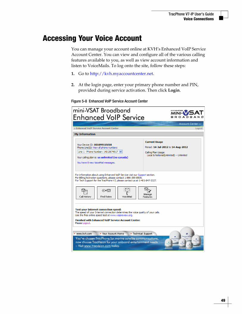
Accessing Your Voice AccountYou can manage your account online at KVH’s Enhanced VoIP Service Account Center. You can view and configure all of the various calling features available to you, as well as view account information and listen to VoiceMails. To log onto the site, follow these steps:
1. Go to http://kvh.myaccountcenter.net.
2. At the login page, enter your primary phone number and PIN, provided during service activation. Then click Login.
Figure 5-8 Enhanced VoIP Service Account Center
49

TracPhone V7-IP User’s Guide
51
Network Configuration
6. Network ConfigurationThis section explains the three main options for connecting your vessel’s computers to the TracPhone system: wired DHCP, wireless DHCP, and static IP. (You can use one, two, or all three configurations to meet your network requirements.) It also provides an overview of the advanced network settings that are available on the CommBox-ACU.
ContentsWired DHCP Configuration............................................... 53
Wireless DHCP Configuration .......................................... 54
Configuring Computers for DHCP .................................... 57
Static IP Configuration..................................................... 61
LAN Settings on CommBox-ACU...................................... 64
Cache Settings on CommBox-ACU .................................. 65
CommBox Settings on CommBox-ACU ............................ 66
TracPhone V7-IP User’s GuideNetwork Configuration
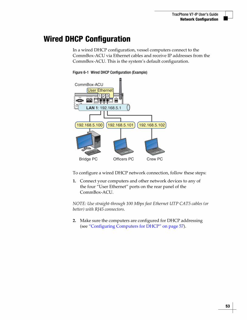
Wired DHCP ConfigurationIn a wired DHCP configuration, vessel computers connect to the CommBox-ACU via Ethernet cables and receive IP addresses from the CommBox-ACU. This is the system’s default configuration.
Figure 6-1 Wired DHCP Configuration (Example)
To configure a wired DHCP network connection, follow these steps:
1. Connect your computers and other network devices to any of the four “User Ethernet” ports on the rear panel of the CommBox-ACU.
NOTE: Use straight-through 100 Mbps fast Ethernet UTP CAT5 cables (or better) with RJ45 connectors.
2. Make sure the computers are configured for DHCP addressing (see “Configuring Computers for DHCP” on page 57).
To ModemRS422 1 2 0
WiFi
1 2 3 4Voice Lines (Analog) User Ethernet PortsEthernet
To Modem
BUC Power24VDC , 2.5AKVH and TracPhone are registered trademarks
of KVH Industries, Inc.; mini-VSAT Broadband is a service mark of KVH Industries, Inc.
Tested to comply with FCC Standards
CAUTIONRISK OF ELECTRIC SHOCK
DO NOT OPEN
1000
User EthernetCommBox-ACU
Bridge PC
1 2 3
Crew PCOfficers PC
192.168.5.100 192.168.5.101 192.168.5.102
LAN 1: 192.168.5.1
53
TracPhone V7-IP User’s Guide
54
Network Configuration
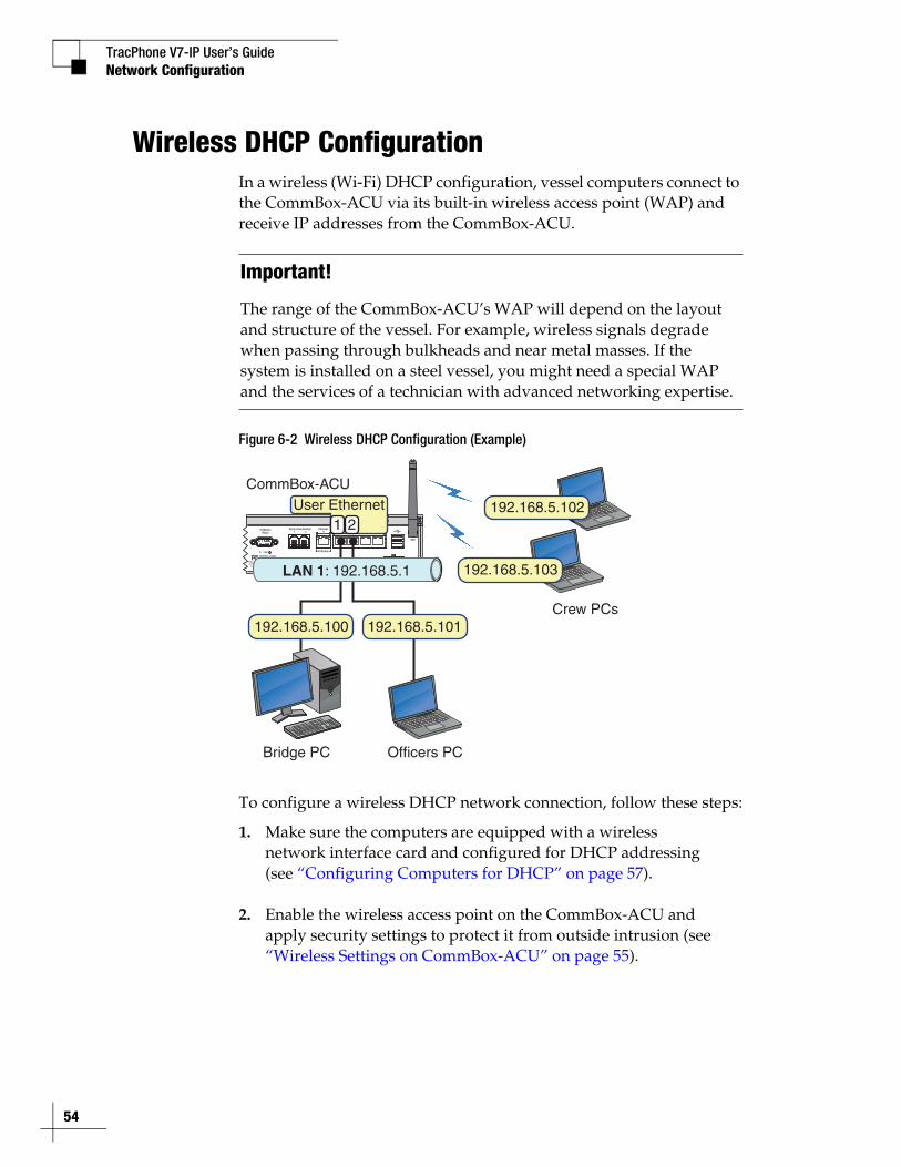
Wireless DHCP ConfigurationIn a wireless (Wi-Fi) DHCP configuration, vessel computers connect to the CommBox-ACU via its built-in wireless access point (WAP) and receive IP addresses from the CommBox-ACU.
Figure 6-2 Wireless DHCP Configuration (Example)
To configure a wireless DHCP network connection, follow these steps:
1. Make sure the computers are equipped with a wireless network interface card and configured for DHCP addressing (see “Configuring Computers for DHCP” on page 57).
2. Enable the wireless access point on the CommBox-ACU and apply security settings to protect it from outside intrusion (see “Wireless Settings on CommBox-ACU” on page 55).
Important!
The range of the CommBox-ACU’s WAP will depend on the layout and structure of the vessel. For example, wireless signals degrade when passing through bulkheads and near metal masses. If the system is installed on a steel vessel, you might need a special WAP and the services of a technician with advanced networking expertise.
To ModemRS422 1 2 0
WiFi
1 2 3 4Voice Lines (Analog) User Ethernet PortsEthernet
To Modem
BUC Power24VDC , 2.5AKVH and TracPhone are registered trademarks
of KVH Industries, Inc.; mini-VSAT Broadband is a service mark of KVH Industries, Inc.
Tested to comply with FCC Standards
CAUTIONRISK OF ELECTRIC SHOCK
DO NOT OPEN
1000
User EthernetCommBox-ACU
Bridge PC
1 2
Crew PCs
Officers PC
192.168.5.100 192.168.5.101
192.168.5.102
192.168.5.103LAN 1: 192.168.5.1
TracPhone V7-IP User’s GuideNetwork Configuration
Wireless Settings on CommBox-ACU
NOTE: If the optional CommBox software is enabled, the CommBox-ACU’s network settings are configured by KVH over the air. The Network Settings page of the CommBox-ACU will not contain any configurable fields. (See “CommBox Features” on page 77 for details about enabling the CommBox software.)
To enable a wireless network connection and protect it from outside intrusion, follow these steps:
1. At the TracPhone V7-IP web interface, click the Settings tab. Then click Network Settings.
2. In Wireless Settings, click Edit.
3. If the Login window appears, log in with the Administrator password.
4. Select Enabled.
5. Set the following wireless options:
SSID: Keep the default name, or enter a unique name for the wireless network.
Security: Select either security type - WPA2 or WEP (128-bit).
Password/Passphrase: If you selected WPA2, enter a password (between 8-20 characters). If you selected WEP, enter a passphrase (must be 13 characters).
Channel: Keep the default channel, or select any other channel for wireless communications.
6. Click Save.
7. At the confirmation message, click Save.
55

TracPhone V7-IP User’s Guide
56
Network Configuration
Figure 6-3 Wireless Settings
TracPhone V7-IP User’s GuideNetwork Configuration
Configuring Computers for DHCPTo configure your computers for DHCP, allowing them to receive IP addresses from the CommBox-ACU, follow the steps for your operating system:
• “Windows 7 or Windows Vista DHCP Settings”
• “Windows XP DHCP Settings” on page 58
• “Mac OS X DHCP Settings” on page 60
NOTE: KVH Technical Support fully supports the four operating systems described here: Windows 7, Windows Vista™, Windows XP, and Macintosh® OS X.
Windows 7 or Windows Vista DHCP Settings
To configure a Windows 7 or Windows Vista computer for DHCP addressing, follow these steps:
1. In Control Panel, double-click Network and Sharing Center. (You might need to click Network and Internet first.) You can find the Control Panel either through the Start menu or “My Computer.”
2. In Network and Sharing Center, double-click the Local Area Connection (Windows 7) or View Status (Windows Vista) for the Ethernet connection you are using for mini-VSAT Broadband.
3. In the Local Area Connection Status dialog box, click Properties. If this screen doesn’t appear, just skip to Step 4.
4. In the Local Area Connection Properties dialog box, click the Networking tab, select Internet Protocol Version 4, and then click Properties.
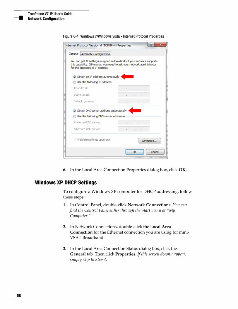
5. In the Internet Protocol Properties dialog box, select Obtain an IP address automatically and Obtain DNS server address automatically. Then click OK.
57
TracPhone V7-IP User’s Guide
58
Network Configuration
Figure 6-4 Windows 7/Windows Vista - Internet Protocol Properties
6. In the Local Area Connection Properties dialog box, click OK.
Windows XP DHCP Settings
To configure a Windows XP computer for DHCP addressing, follow these steps:
1. In Control Panel, double-click Network Connections. You can find the Control Panel either through the Start menu or “My Computer.”
2. In Network Connections, double-click the Local Area Connection for the Ethernet connection you are using for mini-VSAT Broadband.
3. In the Local Area Connection Status dialog box, click the General tab. Then click Properties. If this screen doesn’t appear, simply skip to Step 4.
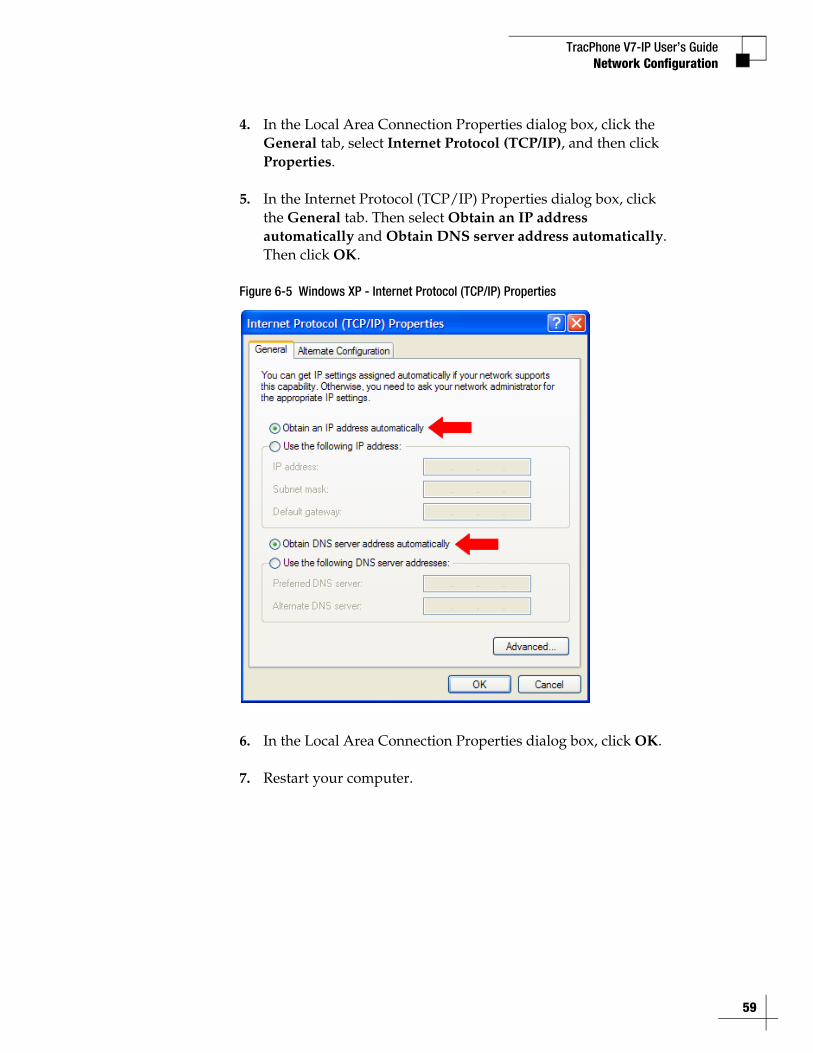
TracPhone V7-IP User’s GuideNetwork Configuration
4. In the Local Area Connection Properties dialog box, click the General tab, select Internet Protocol (TCP/IP), and then click Properties.
5. In the Internet Protocol (TCP/IP) Properties dialog box, click the General tab. Then select Obtain an IP address automatically and Obtain DNS server address automatically. Then click OK.
Figure 6-5 Windows XP - Internet Protocol (TCP/IP) Properties
6. In the Local Area Connection Properties dialog box, click OK.
7. Restart your computer.
59
TracPhone V7-IP User’s Guide
60
Network Configuration
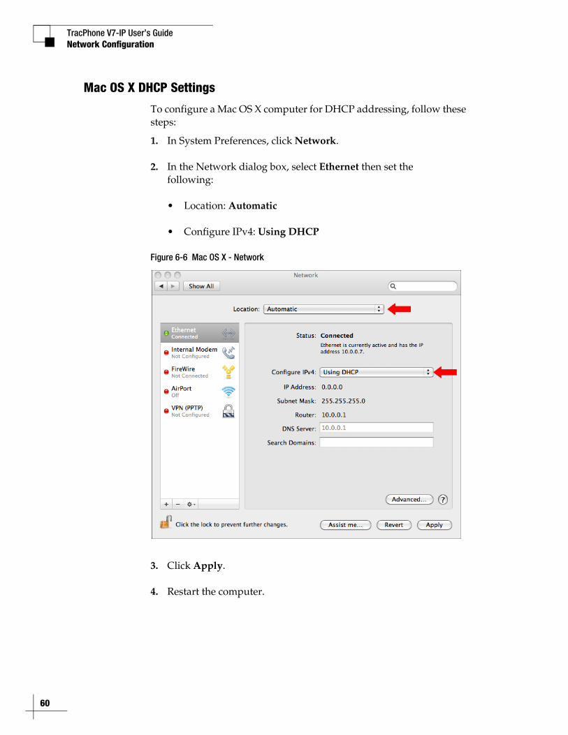
Mac OS X DHCP Settings
To configure a Mac OS X computer for DHCP addressing, follow these steps:
1. In System Preferences, click Network.
2. In the Network dialog box, select Ethernet then set the following:
• Location: Automatic
• Configure IPv4: Using DHCP
Figure 6-6 Mac OS X - Network
3. Click Apply.
4. Restart the computer.
TracPhone V7-IP User’s GuideNetwork Configuration
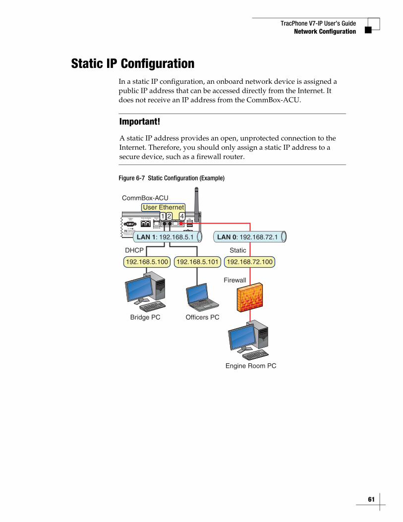
Static IP ConfigurationIn a static IP configuration, an onboard network device is assigned a public IP address that can be accessed directly from the Internet. It does not receive an IP address from the CommBox-ACU.
Figure 6-7 Static Configuration (Example)
Important!
A static IP address provides an open, unprotected connection to the Internet. Therefore, you should only assign a static IP address to a secure device, such as a firewall router.
To ModemRS422 1 2 0
WiFi
1 2 3 4Voice Lines (Analog) User Ethernet PortsEthernet
To Modem
BUC Power24VDC , 2.5AKVH and TracPhone are registered trademarks
of KVH Industries, Inc.; mini-VSAT Broadband is a service mark of KVH Industries, Inc.
Tested to comply with FCC Standards
CAUTIONRISK OF ELECTRIC SHOCK
DO NOT OPEN
1000
User EthernetCommBox-ACU
Bridge PC
1 2 4
DHCP
Engine Room PC
Officers PC
192.168.5.100 192.168.5.101 192.168.72.100
LAN 1: 192.168.5.1 LAN 0: 192.168.72.1
Static
Firewall
61
TracPhone V7-IP User’s Guide
62
Network Configuration
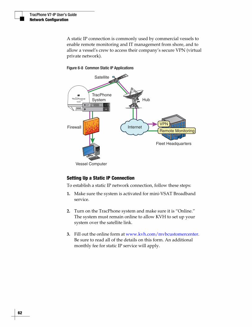
A static IP connection is commonly used by commercial vessels to enable remote monitoring and IT management from shore, and to allow a vessel’s crew to access their company’s secure VPN (virtual private network).
Figure 6-8 Common Static IP Applications
Setting Up a Static IP ConnectionTo establish a static IP network connection, follow these steps:
1. Make sure the system is activated for mini-VSAT Broadband service.
2. Turn on the TracPhone system and make sure it is “Online.” The system must remain online to allow KVH to set up your system over the satellite link.
3. Fill out the online form at www.kvh.com/mvbcustomercenter. Be sure to read all of the details on this form. An additional monthly fee for static IP service will apply.
Satellite
Hub
Fleet Headquarters
TracPhoneSystem
Vessel Computer
InternetVPN
Remote MonitoringFirewall
STATUS
TracPhone V7-IP User’s Guide
63
Network Configuration
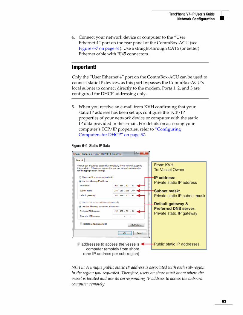
4. Connect your network device or computer to the “User Ethernet 4” port on the rear panel of the CommBox-ACU (see Figure 6-7 on page 61). Use a straight-through CAT5 (or better) Ethernet cable with RJ45 connectors.
5. When you receive an e-mail from KVH confirming that your static IP address has been set up, configure the TCP/IP properties of your network device or computer with the static IP data provided in the e-mail. For details on accessing your computer’s TCP/IP properties, refer to “Configuring Computers for DHCP” on page 57.
Figure 6-9 Static IP Data
NOTE: A unique public static IP address is associated with each sub-region in the region you requested. Therefore, users on shore must know where the vessel is located and use its corresponding IP address to access the onboard computer remotely.
Important!
Only the “User Ethernet 4” port on the CommBox-ACU can be used to connect static IP devices, as this port bypasses the CommBox-ACU’s local subnet to connect directly to the modem. Ports 1, 2, and 3 are configured for DHCP addressing only.
IP address:Private static IP address
From: KVHTo: Vessel Owner
Subnet mask:Private static IP subnet mask
Default gateway &Preferred DNS server:Private static IP gateway
Public static IP addressesIP addresses to access the vessel’scomputer remotely from shore
(one IP address per sub-region)
TracPhone V7-IP User’s Guide
64
Network Configuration
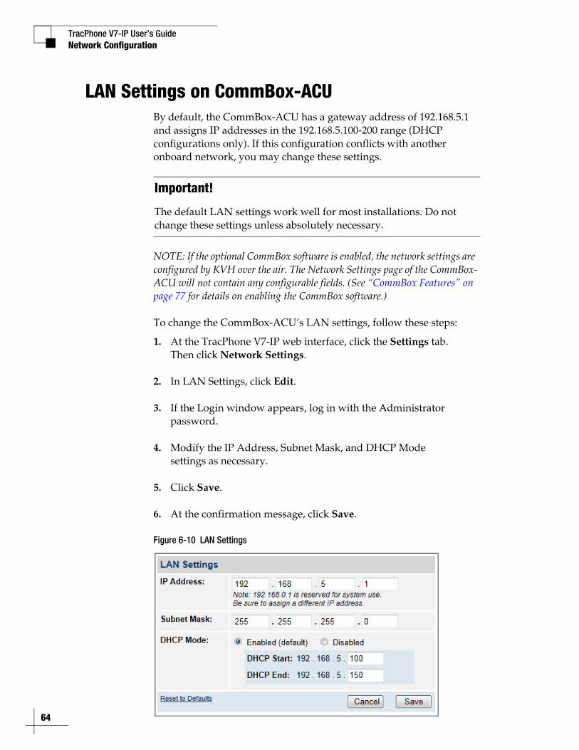
LAN Settings on CommBox-ACUBy default, the CommBox-ACU has a gateway address of 192.168.5.1 and assigns IP addresses in the 192.168.5.100-200 range (DHCP configurations only). If this configuration conflicts with another onboard network, you may change these settings.
NOTE: If the optional CommBox software is enabled, the network settings are configured by KVH over the air. The Network Settings page of the CommBox-ACU will not contain any configurable fields. (See “CommBox Features” on page 77 for details on enabling the CommBox software.)
To change the CommBox-ACU’s LAN settings, follow these steps:
1. At the TracPhone V7-IP web interface, click the Settings tab. Then click Network Settings.
2. In LAN Settings, click Edit.
3. If the Login window appears, log in with the Administrator password.
4. Modify the IP Address, Subnet Mask, and DHCP Mode settings as necessary.
5. Click Save.
6. At the confirmation message, click Save.
Figure 6-10 LAN Settings
Important!
The default LAN settings work well for most installations. Do not change these settings unless absolutely necessary.
TracPhone V7-IP User’s GuideNetwork Configuration
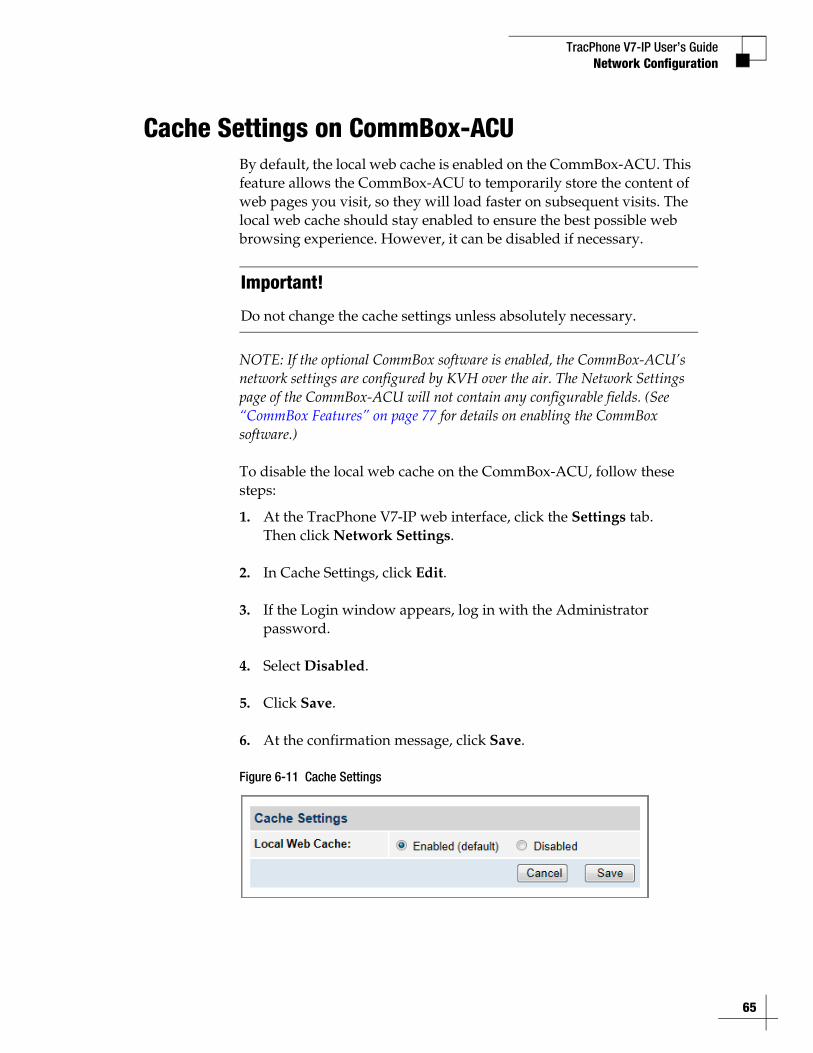
Cache Settings on CommBox-ACUBy default, the local web cache is enabled on the CommBox-ACU. This feature allows the CommBox-ACU to temporarily store the content of web pages you visit, so they will load faster on subsequent visits. The local web cache should stay enabled to ensure the best possible web browsing experience. However, it can be disabled if necessary.
NOTE: If the optional CommBox software is enabled, the CommBox-ACU’s network settings are configured by KVH over the air. The Network Settings page of the CommBox-ACU will not contain any configurable fields. (See “CommBox Features” on page 77 for details on enabling the CommBox software.)
To disable the local web cache on the CommBox-ACU, follow these steps:
1. At the TracPhone V7-IP web interface, click the Settings tab. Then click Network Settings.
2. In Cache Settings, click Edit.
3. If the Login window appears, log in with the Administrator password.
4. Select Disabled.
5. Click Save.
6. At the confirmation message, click Save.
Figure 6-11 Cache Settings
Important!
Do not change the cache settings unless absolutely necessary.
65
TracPhone V7-IP User’s Guide
66
Network Configuration
CommBox Settings on CommBox-ACUIf the optional CommBox software is enabled, the CommBox-ACU’s network settings are configured by KVH over the air. The Network Settings page of the CommBox-ACU will not contain any configurable fields.
NOTE: See “CommBox Features” on page 77 for details on enabling the CommBox software.
For complete details about the CommBox software, refer to the CommBox manual. To view the CommBox manual, follow these steps:
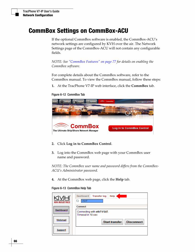
1. At the TracPhone V7-IP web interface, click the CommBox tab.
Figure 6-12 CommBox Tab
2. Click Log in to CommBox Control.
3. Log into the CommBox web page with your CommBox user name and password.
NOTE: The CommBox user name and password differs from the CommBox-ACU’s Administrator password.
4. At the CommBox web page, click the Help tab.
Figure 6-13 CommBox Help Tab
TracPhone V7-IP User’s Guide
67
Data Connections
7. Data ConnectionsThis section explains how to connect to the Internet via the mini-VSAT Broadband service. It also provides a number of suggestions for minimizing the amount of data that’s transferred over the network.
ContentsInternet Access Overview................................................ 69
Tips for Minimizing Data Usage....................................... 70
CommBox Features ......................................................... 77
TracPhone V7-IP User’s Guide
69
Data Connections
Internet Access OverviewWhile the TracPhone system is online with the mini-VSAT Broadband service, you can perform all of the same Internet tasks you perform at home:
• Web browsing
• Weather and chart updates
• Instant messages
• Corporate network access (VPN)
• Data transfers
Connecting to the Internet
To connect to the Internet, follow these steps:
1. Make sure the TracPhone system is online.
2. Open a web browser window on any computer connected to the network.
3. If you’re unable to connect, make sure your computer is configured for DHCP addressing. Refer to “Configuring Computers for DHCP” on page 57.
Important!
High-bandwidth applications, such as peer-to-peer file sharing, web cameras, streaming media, and high-speed gaming, are not supported by fixed rate plans. For details, be sure to read all of the service terms and conditions in the End User Agreement, which can be found at www.kvh.com/mvbcustomercenter.
TracPhone V7-IP User’s Guide
70
Data Connections
Tips for Minimizing Data UsageThe configurations of operating systems, web browsers, and applications generally assume an unlimited, always-on broadband connection. As such, they will often try to connect to the Internet on their own to download updates and transfer files. They will also operate without any regard to the amount of traffic they generate to perform routine tasks.
While high data usage is not much of a concern with a broadband connection on shore, avoiding excessive data usage is worthwhile when using the mini-VSAT Broadband service at sea, especially if you are charged by the megabyte on a metered rate plan.
NOTE: Installing network monitoring software on your computer(s) will allow you to keep track of how much data is downloaded to and uploaded from your computer(s). For the ultimate suite of network management tools, look no further than KVH’s CommBox software – see “CommBox Features” on page 77 for details!
Consider the guidelines in this section to eliminate unnecessary background Internet activity and minimize the amount of data you consume. Adopting these guidelines will help ensure you use the service in the most efficient and cost-effective manner.
Important!
You are responsible for all data transferred to/from your computers, including inadvertent downloads by applications running in the background.
TracPhone V7-IP User’s Guide
71
Data Connections
Preventing Automatic Updates
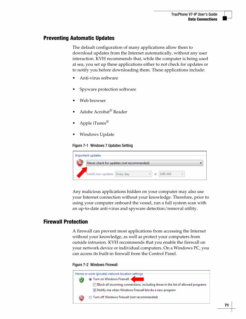
The default configuration of many applications allow them to download updates from the Internet automatically, without any user interaction. KVH recommends that, while the computer is being used at sea, you set up these applications either to not check for updates or to notify you before downloading them. These applications include:
• Anti-virus software
• Spyware protection software
• Web browser
• Adobe Acrobat® Reader
• Apple iTunes®
• Windows Update
Figure 7-1 Windows 7 Updates Setting
Any malicious applications hidden on your computer may also use your Internet connection without your knowledge. Therefore, prior to using your computer onboard the vessel, run a full system scan with an up-to-date anti-virus and spyware detection/removal utility.
Firewall Protection
A firewall can prevent most applications from accessing the Internet without your knowledge, as well as protect your computers from outside intrusion. KVH recommends that you enable the firewall on your network device or individual computers. On a Windows PC, you can access its built-in firewall from the Control Panel.
Figure 7-2 Windows Firewall
TracPhone V7-IP User’s Guide
72
Data Connections
Web Browser Settings
All popular web browsers, such as Internet Explorer, Mozilla Firefox, Google Chrome, and Apple Safari, offer various tools that allow you to minimize the amount of data they consume. Consider these options:
• “Limit Multimedia Downloads”
• “Enable Pop-Up Blocker” on page 73
• “Maximize Caching of Web Pages” on page 74
• “Avoid Multiple Browsing Tabs” on page 74
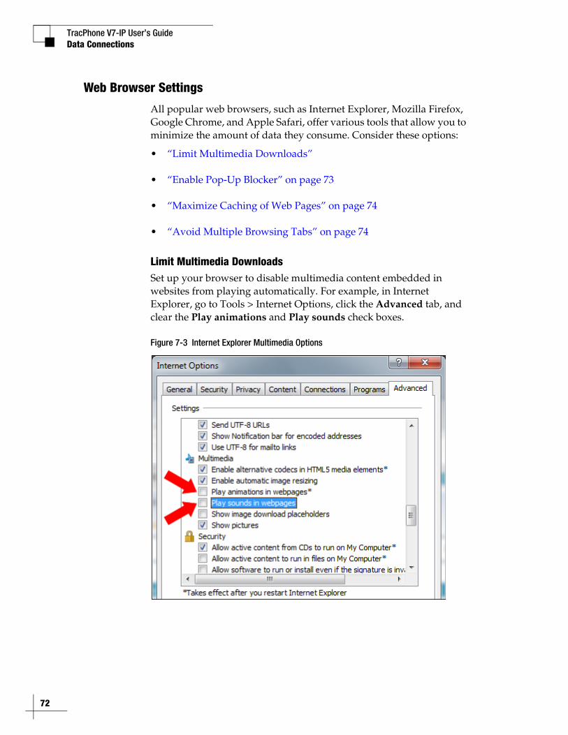
Limit Multimedia DownloadsSet up your browser to disable multimedia content embedded in websites from playing automatically. For example, in Internet Explorer, go to Tools > Internet Options, click the Advanced tab, and clear the Play animations and Play sounds check boxes.
Figure 7-3 Internet Explorer Multimedia Options
TracPhone V7-IP User’s GuideData Connections
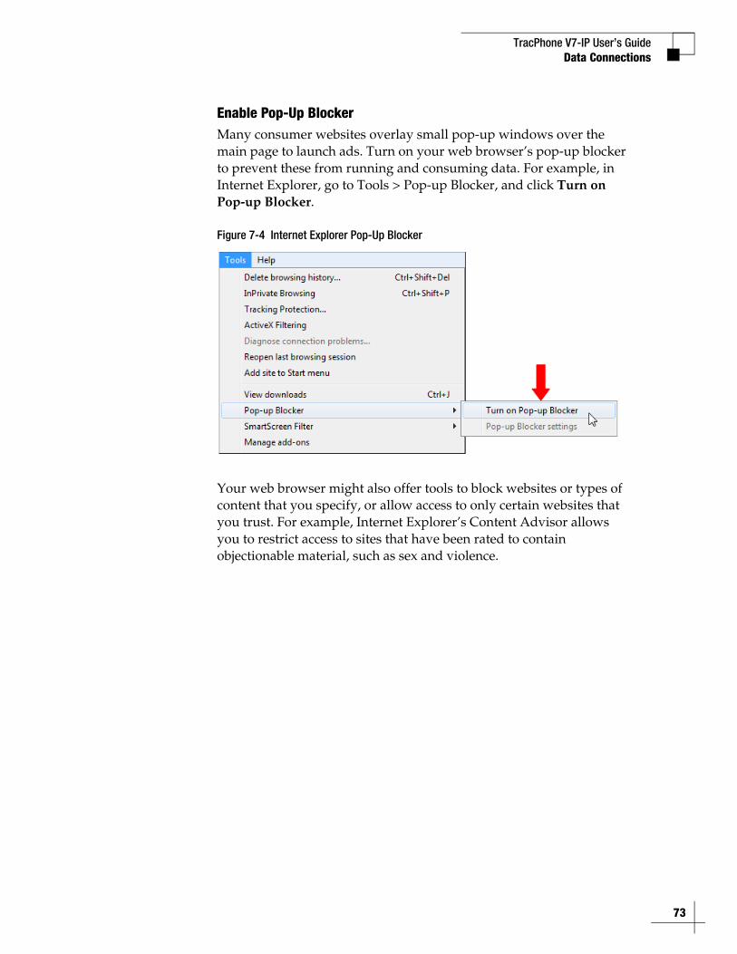
Enable Pop-Up BlockerMany consumer websites overlay small pop-up windows over the main page to launch ads. Turn on your web browser’s pop-up blocker to prevent these from running and consuming data. For example, in Internet Explorer, go to Tools > Pop-up Blocker, and click Turn on Pop-up Blocker.
Figure 7-4 Internet Explorer Pop-Up Blocker
Your web browser might also offer tools to block websites or types of content that you specify, or allow access to only certain websites that you trust. For example, Internet Explorer’s Content Advisor allows you to restrict access to sites that have been rated to contain objectionable material, such as sex and violence.
73
TracPhone V7-IP User’s Guide
74
Data Connections
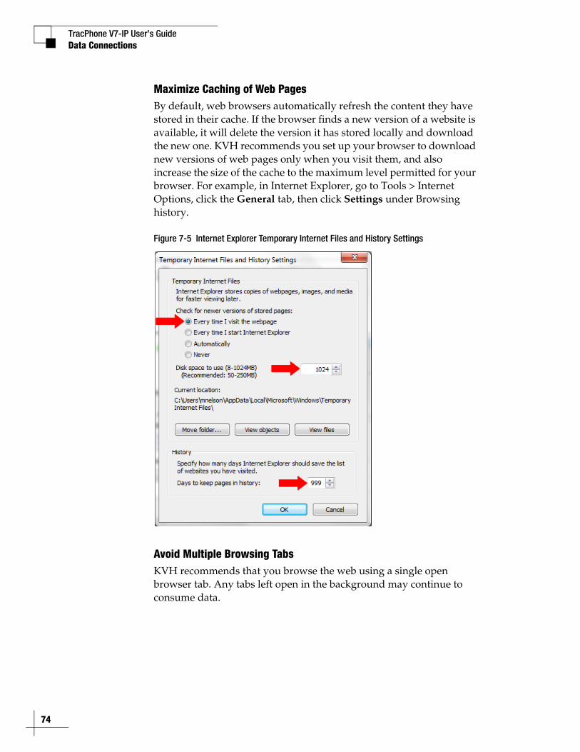
Maximize Caching of Web PagesBy default, web browsers automatically refresh the content they have stored in their cache. If the browser finds a new version of a website is available, it will delete the version it has stored locally and download the new one. KVH recommends you set up your browser to download new versions of web pages only when you visit them, and also increase the size of the cache to the maximum level permitted for your browser. For example, in Internet Explorer, go to Tools > Internet Options, click the General tab, then click Settings under Browsing history.
Figure 7-5 Internet Explorer Temporary Internet Files and History Settings
Avoid Multiple Browsing TabsKVH recommends that you browse the web using a single open browser tab. Any tabs left open in the background may continue to consume data.
TracPhone V7-IP User’s GuideData Connections
Data-Intensive Applications
The following applications can consume a great deal of data whenever they are active or running in the background:
• Skype (uses 40 MB per month just to maintain your status, in addition to the data used for actual calls and chats)
• RSS feeds and widgets presenting real-time information (e.g., news, weather, stocks ticker, sports scores, etc.)
• Social media (e.g., YouTube and Facebook)
• Peer-to-peer (P2P) file sharing (e.g., BitTorrent, Gnutella, etc.)
If you are charged by the megabyte on a metered rate plan, use caution when running these types of applications to help prevent unpleasant surprises on your airtime bill.
Mobile Websites
Many organizations now offer alternative versions of their websites optimized for mobile devices. Although designed for smartphone users on a cellular connection, you can access these mobile websites on a desktop or laptop as well. KVH recommends you visit mobile websites instead of full sites whenever possible to minimize the amount of data used.
To view the mobile version of a website, simply replace the “www” in the address with an “m”. For example, to view the mobile version of CNN’s website, you would enter “m.cnn.com” in your web browser.
Important!
Some high-bandwidth applications, such as peer-to-peer file sharing, web cameras, streaming media, and high-speed gaming, are not supported by fixed rate plans. For details, be sure to read all of the service terms and conditions in the End User Agreement, which can be found at www.kvh.com/mvbcustomercenter.
75
TracPhone V7-IP User’s Guide
76
Data Connections
E-mail Best Practices
There are several ways to reduce the amount of data your e-mail application uses. Consider the following e-mail best practices:
• Use an IMAP (Interactive Mail Access Protocol) server instead of traditional POP3 (Post Office Protocol 3).
• Disable automatic sending/receiving of new mail.
• Send messages in plain text rather than HTML format.
• Compress all attachments.
• Disable automatic signatures and read receipts.
TracPhone V7-IP User’s GuideData Connections
CommBox FeaturesThe optional CommBox software extends the network capabilities of the CommBox-ACU to improve crew morale, streamline operations, improve efficiency, and reduce costs. Two options are available:
• CommBox Standard Bundle (KVH part no. 35-0010): Provides least cost routing, onboard firewall, bandwidth management, web caching, web image compression, ad removal, and URL and content filtering
• CommBox Enterprise Bundle (KVH part no. 35-0011): Provides everything included in the Standard bundle, plus automated file transfers, differential synchronization, mail relay server, web mail client, anti-spam and anti-virus filters, roaming crew accounts, and prepaid Internet and e-mail services
NOTE: The CommBox Enterprise Bundle requires integration with a CommBox hub.
Purchasing a CommBox BundleTo learn more about CommBox’s powerful suite of network management features, go to the TracPhone V7-IP web interface and click the CommBox tab. Then contact KVH Network Services at [email protected] for a consultation. KVH will coordinate with you to select, install, and configure the appropriate bundle to meet your needs.
Accessing the CommBox Web Interface
If a CommBox software bundle is enabled on the CommBox-ACU, follow these steps to access the CommBox web interface:
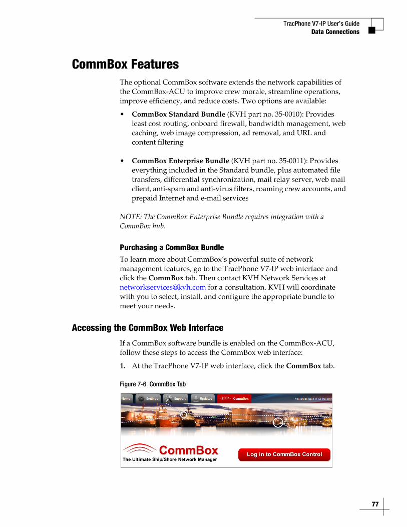
1. At the TracPhone V7-IP web interface, click the CommBox tab.
Figure 7-6 CommBox Tab
77
TracPhone V7-IP User’s Guide
78
Data Connections
2. Click Log in to CommBox Control.
3. Log into the CommBox web interface with your CommBox user name and password.
NOTE: The CommBox user name and password differs from the CommBox-ACU’s Administrator password.
For more details about how to use the CommBox, refer to the CommBox manual available on the Help tab of the CommBox web interface.
Figure 7-7 CommBox Help Tab
TracPhone V7-IP User’s Guide
79
Troubleshooting
8. TroubleshootingThis section identifies some basic problems along with their possible causes and solutions. It also explains what the error messages, status messages, and LED conditions indicate, how to view and export the system logs, and how to get technical support.
ContentsInitial Steps for Any Problem ........................................... 81
Troubleshooting a Voice Problem.................................... 83
Troubleshooting a Data Problem ..................................... 85
Error Messages ............................................................... 87
Status Information ........................................................... 91
LED Indicators ............................................................... 101
System Logs .................................................................. 104
Equipment ID Numbers.................................................. 106
Software Versions ......................................................... 107
Technical Support.......................................................... 108
TracPhone V7-IP User’s GuideTroubleshooting
Initial Steps for Any ProblemIf you are experiencing a problem with your TracPhone system, first follow these basic steps:
Step 1a: Check System Status Information on the Web InterfaceOpen a web browser window on any computer on the network and enter http://minivsat.kvh to access the TracPhone V7-IP web interface.
NOTE: This web address may not work on all platforms and browsers. If the web interface does not appear, enter the CommBox-ACU’s IP address instead (default is 192.168.5.1). You can find this address on the CommBox-ACU front panel LCD (go to Settings > Network Settings > IP Assignments).
The Home page provides system status information. Check the following:
• Connection Status: “Online” indicates the system is connected to the mini-VSAT Broadband service.
• Antenna State: “Tracking” indicates the antenna is tracking the satellite.
• My Phone: “Online & Ready” indicates the CommBox-ACU’s built-in MTA is connected to the enhanced voice service.
If a status message differs from the normal indications listed above, refer to “Status Information” on page 91. If an error message is displayed, refer to “Error Messages” on page 87.
Step 1b: Check System Status Information on the Modem and CommBox-ACU Front PanelsIf you are unable to connect to the web interface, you can find similar status information on the front of the modem and CommBox-ACU. Check the following:
• CommBox-ACU LCD: “Online Tracking” indicates the system is connected to the mini-VSAT Broadband service and the antenna is tracking the satellite.
• LEDs: All LEDs should be lit green.
If a status message differs from the normal indication listed above, refer to “Status Information” on page 91. If an error message is displayed, refer to “Error Messages” on page 87. If an LED is not lit green, refer to “LED Indicators” on page 101.
81
TracPhone V7-IP User’s Guide
82
Troubleshooting
Step 2: Check for BlockageIf the antenna is continuously searching for the satellite, check the area around the antenna for blockage. The antenna needs an unobstructed view of the sky to receive satellite signals. Common causes of blockage include other onboard masts or structures, severe weather, and nearby buildings, bridges, trees, or other vessels.
NOTE: You can determine which direction the antenna is pointing by viewing the Home page on the web interface or the “CURRENT AZ/EL” status message on the CommBox-ACU front panel LCD (go to Status > Antenna/ACU Status> Current Az/El).
If there is no blockage, you might be located outside of the mini-VSAT Broadband service coverage area (for a coverage map, visit www.kvh.com/minivsatmap).
Step 3: Try Accessing the KVH Test PageTry accessing the KVH test page at http://208.83.165.11/mbbtest. If the KVH test page appears in your browser, but you still can’t access any other web page, there might be an account or hub issue – contact KVH Technical Support (see “Technical Support” on page 108).
Step 4: Check Power and CablesMake sure power is applied to all system components, including the modem and CommBox-ACU. Also make sure all cables are connected tightly.
Step 5: Restart the SystemTry restarting the system at the TracPhone V7-IP web interface (see “Hardware Restart” on page 127). If you cannot access the web interface, turn off the CommBox-ACU and modem at the front panels, then turn them back on.
NOTE: You cannot restart the modem from the web interface. If you suspect the modem is locked up, try turning it off at the front panel, then turning it back on.
TracPhone V7-IP User’s GuideTroubleshooting
Troubleshooting a Voice ProblemIf you are unable to make a voice call, follow these steps:
Step 1: Check the BasicsComplete the initial steps described in “Initial Steps for Any Problem” on page 81.
Step 2: Make Sure You Are Dialing the Number ProperlyAs explained in “Making a Ship-to-Shore Call” on page 38, if you are dialing a number outside the country assigned to Line 1, you need to dial the appropriate international prefix and country code, in addition to the area/city code and local phone number. For example, if your Line 1 is assigned a United States phone number and you are calling a number outside of the U.S., you need to dial 011 + Country Code + Area Code + Local Phone Number.
Step 3: Check the My Phone Status on the Web InterfaceAt the TracPhone V7-IP web interface, go to the Home page and check the My Phone status information. If it shows “Unable to Register Voice Service,” there is an account or activation issue - contact KVH Technical Support (see “Technical Support” on page 108). The My Phone status also shows the status of phone lines 1 and 2.
Step 4: Restart the MTAThe MTA built into the CommBox-ACU might need to download an updated configuration file from the network. Try restarting the MTA at the TracPhone V7-IP web interface (see “Hardware Restart” on page 127).
Step 5: Verify the MTA Obtained an IP AddressThe MTA must receive an IP address from the CommBox-ACU in order to provide a voice connection. Pick up the handset on any phone connected to the CommBox-ACU and press ***1 on the keypad. If you hear “0.0.0.0” in the handset, the MTA did not receive a valid IP address. Contact KVH Technical Support for assistance (see “Technical Support” on page 108).
83
TracPhone V7-IP User’s Guide
84
Troubleshooting
Step 6: Try a Different PhoneDisconnect the phone from the CommBox-ACU and connect another phone in its place (use a phone that you know is working properly). If you are then able to place a call with the new phone, the phone you were using is faulty.
Step 7: Verify the Phone Is Connected ProperlyMake sure your phone is connected to one of the RJ11 “Voice Line” jacks on the CommBox-ACU (“Voice Line 1” is the primary jack). If you are not receiving calls as expected via a virtual number, make sure your phone is connected to the “Voice Line” jack that is assigned that virtual number.
TracPhone V7-IP User’s GuideTroubleshooting
Troubleshooting a Data Problem If you are unable to access the Internet, follow these steps:
Step 1: Check the BasicsComplete the initial steps described in “Initial Steps for Any Problem” on page 81.
Step 2: Check Your Computer’s DHCP ConfigurationUnless you have set up a static IP address, your computer’s TCP/IP settings need to be configured for DHCP addressing, which allows the CommBox-ACU to assign it an IP address. Refer to “Configuring Computers for DHCP” on page 57 for details.
Step 3: Try a Direct Wired ConnectionConnect your computer directly to the “Ethernet 1” port on the back of the CommBox-ACU using an Ethernet cable. Then restart your computer. If you are now able to access the Internet, there is a problem with your vessel’s network.
Step 4: Ping the Network ConnectionsThe Ping command sends a test packet to any IP address you choose and reports how long it takes to receive a response.
To send a Ping on a Windows PC:Open a Command Prompt window (go to Start > Run, then type cmd). Then, at the command prompt, type ping <IP address>.
To send a Ping on a Mac:Open the Network Utility (go to Finder > Utilities > Network Utility). Then, in the Ping tab, type the IP address then click Ping.
Ping the IP address of the CommBox-ACU. You can find the IP address on the front panel LCD (go to Settings > Network Settings > IP Assignments). The default IP address is 192.168.5.1. All packets sent should be received. If packets are lost, your computer is not connected properly to the CommBox-ACU.
Ping 4.2.2.1 to check your connection to the Internet. All packets sent should be received within 580-900 ms. If the ping fails, contact KVH Technical Support (see “Technical Support” on page 108).
85
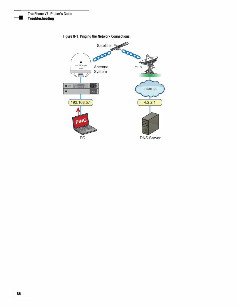
TracPhone V7-IP User’s Guide
86
Troubleshooting
Figure 8-1 Pinging the Network Connections
AntennaSystem
PC
Satellite
Hub
Internet
DNS Server
PING
192.168.5.1 4.2.2.1
STATUS
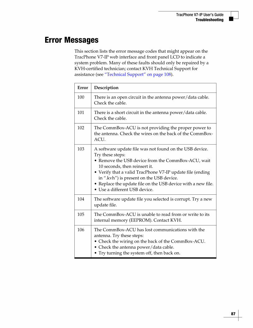
TracPhone V7-IP User’s GuideTroubleshooting
Error MessagesThis section lists the error message codes that might appear on the TracPhone V7-IP web interface and front panel LCD to indicate a system problem. Many of these faults should only be repaired by a KVH-certified technician; contact KVH Technical Support for assistance (see “Technical Support” on page 108).
Error Description
100 There is an open circuit in the antenna power/data cable. Check the cable.
101 There is a short circuit in the antenna power/data cable. Check the cable.
102 The CommBox-ACU is not providing the proper power to the antenna. Check the wires on the back of the CommBox-ACU.
103 A software update file was not found on the USB device. Try these steps:• Remove the USB device from the CommBox-ACU, wait
10 seconds, then reinsert it.• Verify that a valid TracPhone V7-IP update file (ending
in “.kvh”) is present on the USB device.• Replace the update file on the USB device with a new file.• Use a different USB device.
104 The software update file you selected is corrupt. Try a new update file.
105 The CommBox-ACU is unable to read from or write to its internal memory (EEPROM). Contact KVH.
106 The CommBox-ACU has lost communications with the antenna. Try these steps:• Check the wiring on the back of the CommBox-ACU.• Check the antenna power/data cable. • Try turning the system off, then back on.
87
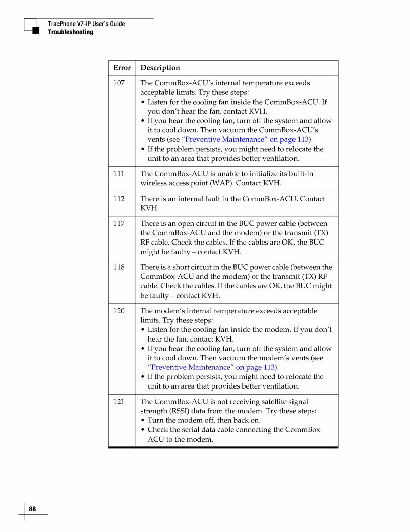
TracPhone V7-IP User’s Guide
88
Troubleshooting
107 The CommBox-ACU’s internal temperature exceeds acceptable limits. Try these steps:• Listen for the cooling fan inside the CommBox-ACU. If
you don’t hear the fan, contact KVH.• If you hear the cooling fan, turn off the system and allow
it to cool down. Then vacuum the CommBox-ACU’s vents (see “Preventive Maintenance” on page 113).
• If the problem persists, you might need to relocate the unit to an area that provides better ventilation.
111 The CommBox-ACU is unable to initialize its built-in wireless access point (WAP). Contact KVH.
112 There is an internal fault in the CommBox-ACU. Contact KVH.
117 There is an open circuit in the BUC power cable (between the CommBox-ACU and the modem) or the transmit (TX) RF cable. Check the cables. If the cables are OK, the BUC might be faulty – contact KVH.
118 There is a short circuit in the BUC power cable (between the CommBox-ACU and the modem) or the transmit (TX) RF cable. Check the cables. If the cables are OK, the BUC might be faulty – contact KVH.
120 The modem’s internal temperature exceeds acceptable limits. Try these steps:• Listen for the cooling fan inside the modem. If you don’t
hear the fan, contact KVH.• If you hear the cooling fan, turn off the system and allow
it to cool down. Then vacuum the modem’s vents (see “Preventive Maintenance” on page 113).
• If the problem persists, you might need to relocate the unit to an area that provides better ventilation.
121 The CommBox-ACU is not receiving satellite signal strength (RSSI) data from the modem. Try these steps:• Turn the modem off, then back on.• Check the serial data cable connecting the CommBox-
ACU to the modem.
Error Description
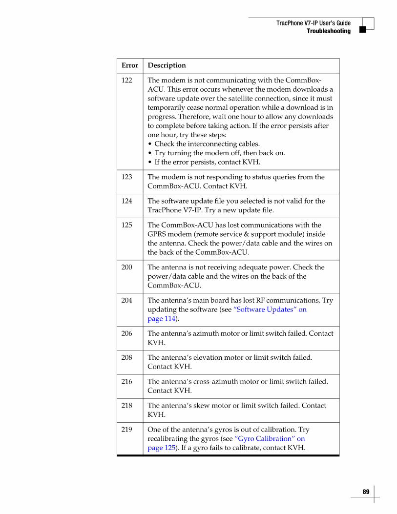
TracPhone V7-IP User’s GuideTroubleshooting
122 The modem is not communicating with the CommBox-ACU. This error occurs whenever the modem downloads a software update over the satellite connection, since it must temporarily cease normal operation while a download is in progress. Therefore, wait one hour to allow any downloads to complete before taking action. If the error persists after one hour, try these steps:• Check the interconnecting cables.• Try turning the modem off, then back on.• If the error persists, contact KVH.
123 The modem is not responding to status queries from the CommBox-ACU. Contact KVH.
124 The software update file you selected is not valid for the TracPhone V7-IP. Try a new update file.
125 The CommBox-ACU has lost communications with the GPRS modem (remote service & support module) inside the antenna. Check the power/data cable and the wires on the back of the CommBox-ACU.
200 The antenna is not receiving adequate power. Check the power/data cable and the wires on the back of the CommBox-ACU.
204 The antenna’s main board has lost RF communications. Try updating the software (see “Software Updates” on page 114).
206 The antenna’s azimuth motor or limit switch failed. Contact KVH.
208 The antenna’s elevation motor or limit switch failed. Contact KVH.
216 The antenna’s cross-azimuth motor or limit switch failed. Contact KVH.
218 The antenna’s skew motor or limit switch failed. Contact KVH.
219 One of the antenna’s gyros is out of calibration. Try recalibrating the gyros (see “Gyro Calibration” on page 125). If a gyro fails to calibrate, contact KVH.
Error Description
89
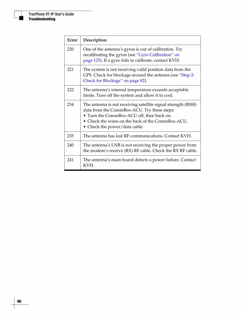
TracPhone V7-IP User’s Guide
90
Troubleshooting
220 One of the antenna’s gyros is out of calibration. Try recalibrating the gyros (see “Gyro Calibration” on page 125). If a gyro fails to calibrate, contact KVH.
221 The system is not receiving valid position data from the GPS. Check for blockage around the antenna (see “Step 2: Check for Blockage” on page 82).
222 The antenna’s internal temperature exceeds acceptable limits. Turn off the system and allow it to cool.
234 The antenna is not receiving satellite signal strength (RSSI) data from the CommBox-ACU. Try these steps:• Turn the CommBox-ACU off, then back on.• Check the wires on the back of the CommBox-ACU.• Check the power/data cable.
235 The antenna has lost RF communications. Contact KVH.
240 The antenna’s LNB is not receiving the proper power from the modem’s receive (RX) RF cable. Check the RX RF cable.
241 The antenna’s main board detects a power failure. Contact KVH.
Error Description
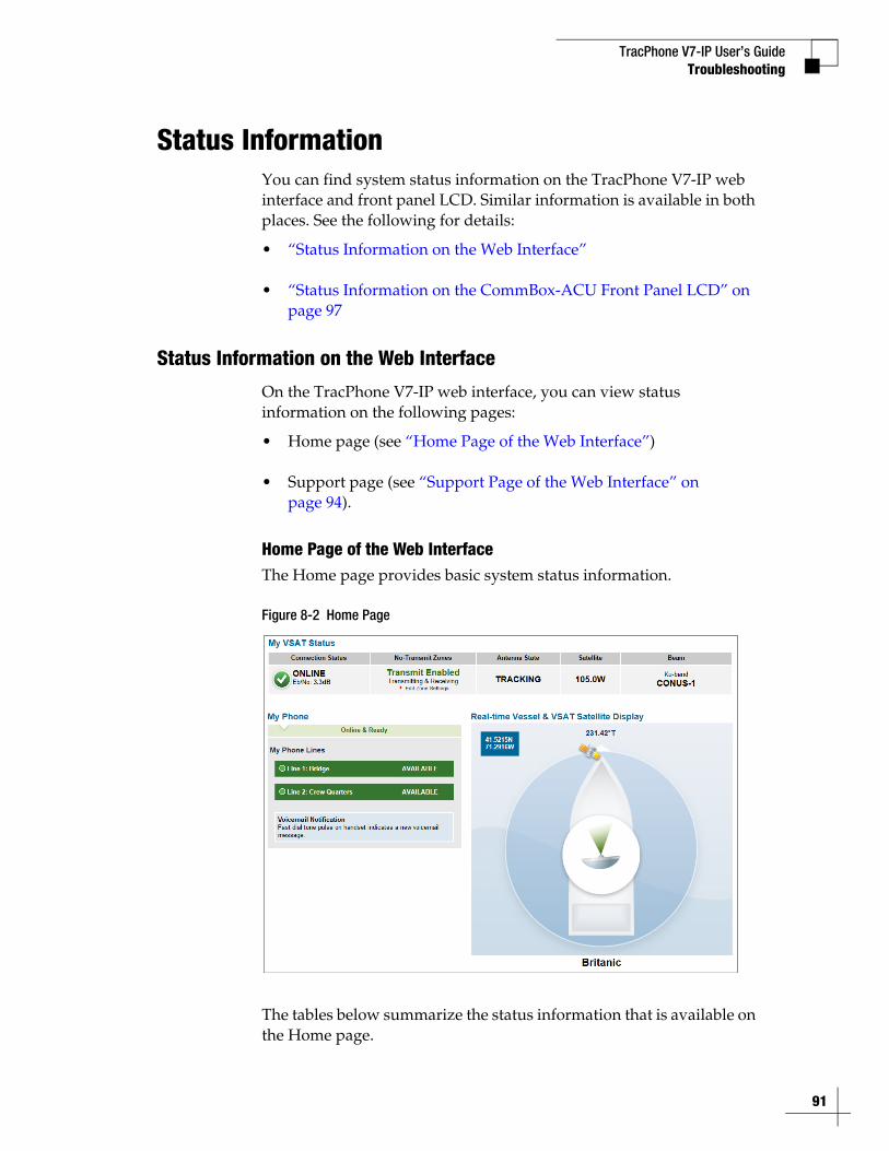
TracPhone V7-IP User’s GuideTroubleshooting
Status InformationYou can find system status information on the TracPhone V7-IP web interface and front panel LCD. Similar information is available in both places. See the following for details:
• “Status Information on the Web Interface”
• “Status Information on the CommBox-ACU Front Panel LCD” on page 97
Status Information on the Web Interface
On the TracPhone V7-IP web interface, you can view status information on the following pages:
• Home page (see “Home Page of the Web Interface”)
• Support page (see “Support Page of the Web Interface” on page 94).
Home Page of the Web InterfaceThe Home page provides basic system status information.
Figure 8-2 Home Page
The tables below summarize the status information that is available on the Home page.
91
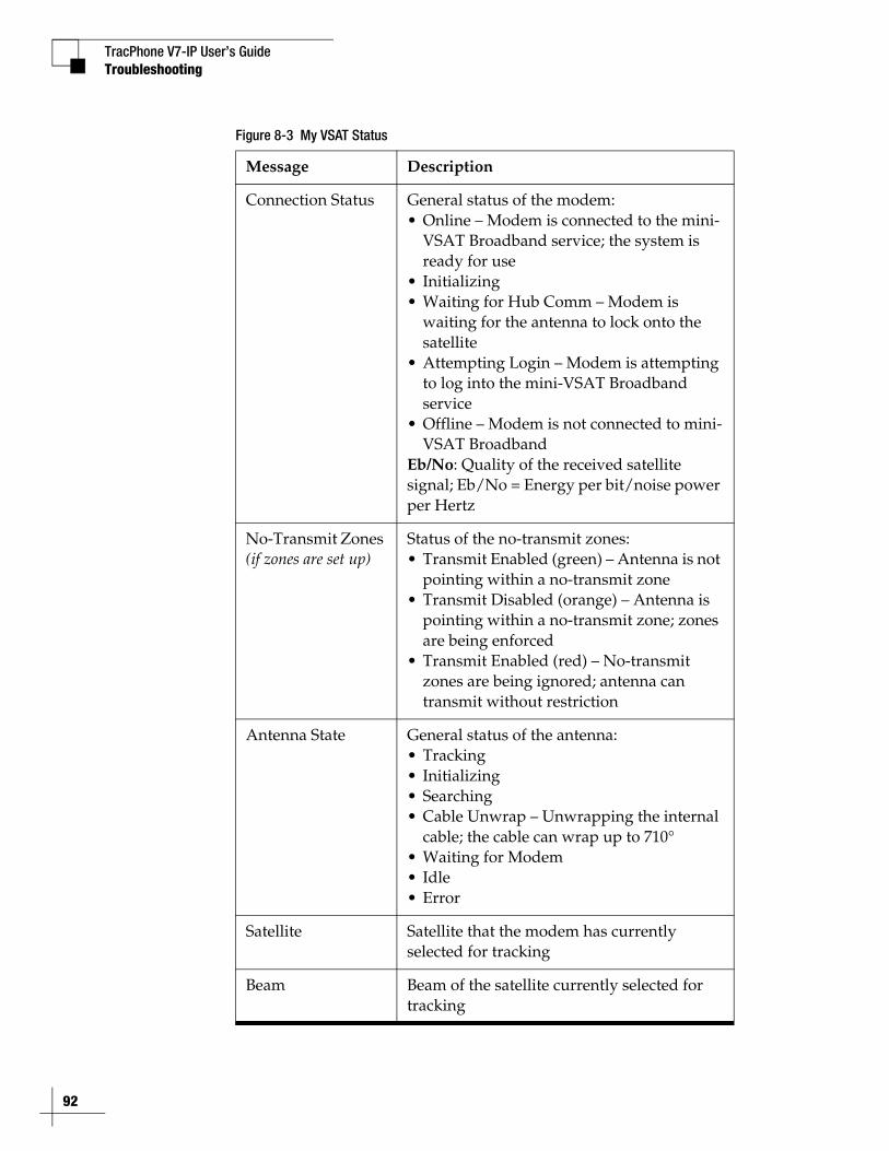
TracPhone V7-IP User’s Guide
92
Troubleshooting
Figure 8-3 My VSAT Status
Message Description
Connection Status General status of the modem:• Online – Modem is connected to the mini-
VSAT Broadband service; the system is ready for use
• Initializing• Waiting for Hub Comm – Modem is
waiting for the antenna to lock onto the satellite
• Attempting Login – Modem is attempting to log into the mini-VSAT Broadband service
• Offline – Modem is not connected to mini-VSAT Broadband
Eb/No: Quality of the received satellite signal; Eb/No = Energy per bit/noise power per Hertz
No-Transmit Zones (if zones are set up)
Status of the no-transmit zones:• Transmit Enabled (green) – Antenna is not
pointing within a no-transmit zone• Transmit Disabled (orange) – Antenna is
pointing within a no-transmit zone; zones are being enforced
• Transmit Enabled (red) – No-transmit zones are being ignored; antenna can transmit without restriction
Antenna State General status of the antenna:• Tracking• Initializing• Searching• Cable Unwrap – Unwrapping the internal
cable; the cable can wrap up to 710°• Waiting for Modem• Idle• Error
Satellite Satellite that the modem has currently selected for tracking
Beam Beam of the satellite currently selected for tracking
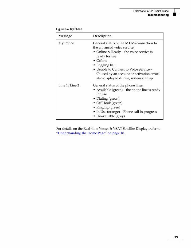
TracPhone V7-IP User’s GuideTroubleshooting
Figure 8-4 My Phone
For details on the Real-time Vessel & VSAT Satellite Display, refer to “Understanding the Home Page” on page 18.
Message Description
My Phone General status of the MTA’s connection to the enhanced voice service:• Online & Ready – the voice service is
ready for use• Offline• Logging In...• Unable to Connect to Voice Service –
Caused by an account or activation error; also displayed during system startup
Line 1/Line 2 General status of the phone lines:• Available (green) – the phone line is ready
for use• Dialing (green)• Off Hook (green)• Ringing (green)• In Use (orange) – Phone call in progress• Unavailable (gray)
93
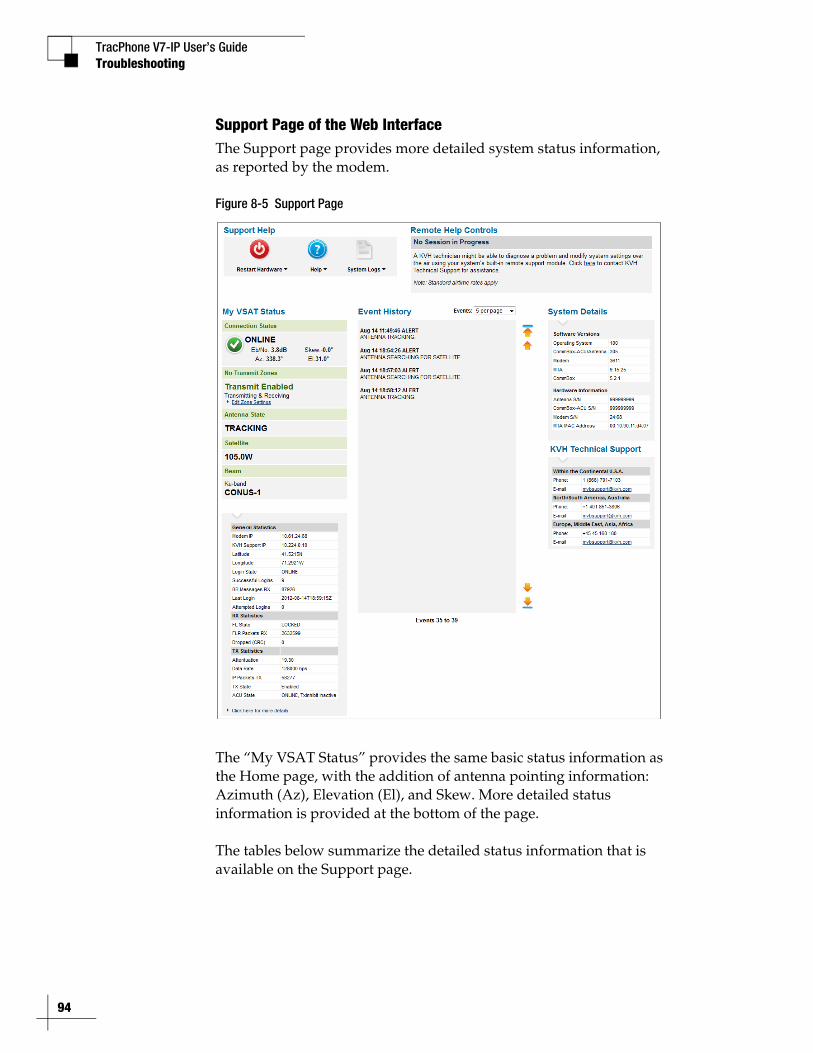
TracPhone V7-IP User’s Guide
94
Troubleshooting
Support Page of the Web InterfaceThe Support page provides more detailed system status information, as reported by the modem.
Figure 8-5 Support Page
The “My VSAT Status” provides the same basic status information as the Home page, with the addition of antenna pointing information: Azimuth (Az), Elevation (El), and Skew. More detailed status information is provided at the bottom of the page.
The tables below summarize the detailed status information that is available on the Support page.
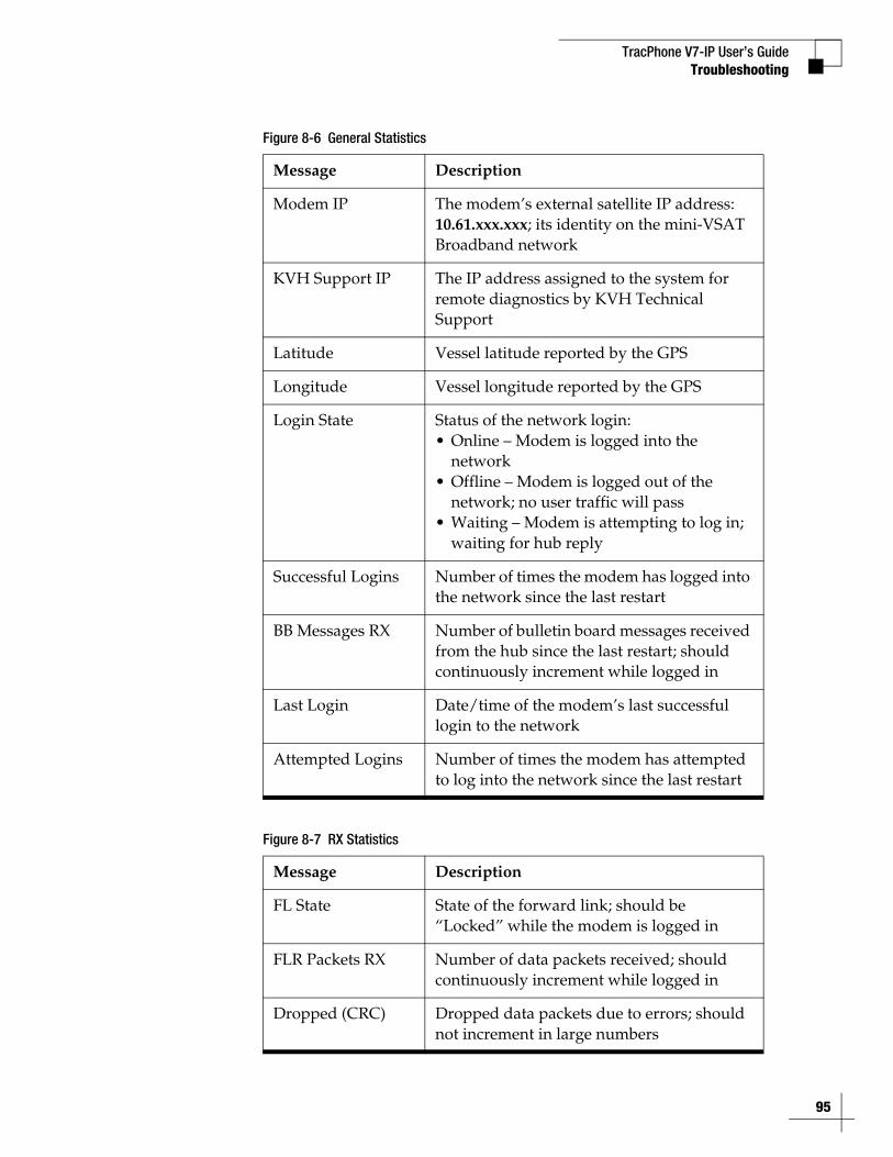
TracPhone V7-IP User’s GuideTroubleshooting
Figure 8-6 General Statistics
Figure 8-7 RX Statistics
Message Description
Modem IP The modem’s external satellite IP address: 10.61.xxx.xxx; its identity on the mini-VSAT Broadband network
KVH Support IP The IP address assigned to the system for remote diagnostics by KVH Technical Support
Latitude Vessel latitude reported by the GPS
Longitude Vessel longitude reported by the GPS
Login State Status of the network login:• Online – Modem is logged into the
network• Offline – Modem is logged out of the
network; no user traffic will pass• Waiting – Modem is attempting to log in;
waiting for hub reply
Successful Logins Number of times the modem has logged into the network since the last restart
BB Messages RX Number of bulletin board messages received from the hub since the last restart; should continuously increment while logged in
Last Login Date/time of the modem’s last successful login to the network
Attempted Logins Number of times the modem has attempted to log into the network since the last restart
Message Description
FL State State of the forward link; should be “Locked” while the modem is logged in
FLR Packets RX Number of data packets received; should continuously increment while logged in
Dropped (CRC) Dropped data packets due to errors; should not increment in large numbers
95
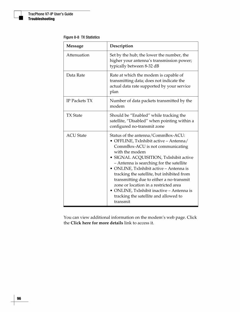
TracPhone V7-IP User’s Guide
96
Troubleshooting
Figure 8-8 TX Statistics
You can view additional information on the modem’s web page. Click the Click here for more details link to access it.
Message Description
Attenuation Set by the hub; the lower the number, the higher your antenna’s transmission power; typically between 8-32 dB
Data Rate Rate at which the modem is capable of transmitting data; does not indicate the actual data rate supported by your service plan
IP Packets TX Number of data packets transmitted by the modem
TX State Should be “Enabled” while tracking the satellite, “Disabled” when pointing within a configured no-transmit zone
ACU State Status of the antenna/CommBox-ACU:• OFFLINE, TxInhibit active – Antenna/
CommBox-ACU is not communicating with the modem
• SIGNAL ACQUISITION, TxInhibit active – Antenna is searching for the satellite
• ONLINE, TxInhibit active – Antenna is tracking the satellite, but inhibited from transmitting due to either a no-transmit zone or location in a restricted area
• ONLINE, TxInhibit inactive – Antenna is tracking the satellite and allowed to transmit

TracPhone V7-IP User’s GuideTroubleshooting
Status Information on the CommBox-ACU Front Panel LCD
On the front panel of the CommBox-ACU, you can view much of the same status information that’s available on the web interface.
To view the status information, follow these steps:
1. Press MENUS on the CommBox-ACU’s front panel to bring up the Status menu.
2. Press ACCEPT to access the status menu. Then use the MENUS and ACCEPT buttons to scroll through the submenus.
Figure 8-9 Status Menu on CommBox-ACU Front Panel
STATUS NEXT SELECT EXIT
MODEM/NETWORK STATUS NEXT SELECT EXIT
ANTENNA/ACU STATUS NEXT SELECT EXIT
GPS/HEADING STATUS NEXT SELECT EXIT
Press ACCEPT to view the status infoon each submenu.
MTA/RSM(GPRS) STATUS NEXT SELECT EXIT
97
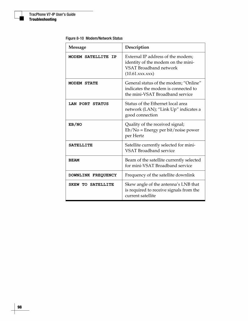
TracPhone V7-IP User’s Guide
98
Troubleshooting
Figure 8-10 Modem/Network Status
Message Description
MODEM SATELLITE IP External IP address of the modem; identity of the modem on the mini-VSAT Broadband network (10.61.xxx.xxx)
MODEM STATE General status of the modem; “Online” indicates the modem is connected to the mini-VSAT Broadband service
LAN PORT STATUS Status of the Ethernet local area network (LAN); “Link Up” indicates a good connection
EB/NO Quality of the received signal;Eb/No = Energy per bit/noise power per Hertz
SATELLITE Satellite currently selected for mini-VSAT Broadband service
BEAM Beam of the satellite currently selected for mini-VSAT Broadband service
DOWNLINK FREQUENCY Frequency of the satellite downlink
SKEW TO SATELLITE Skew angle of the antenna’s LNB that is required to receive signals from the current satellite
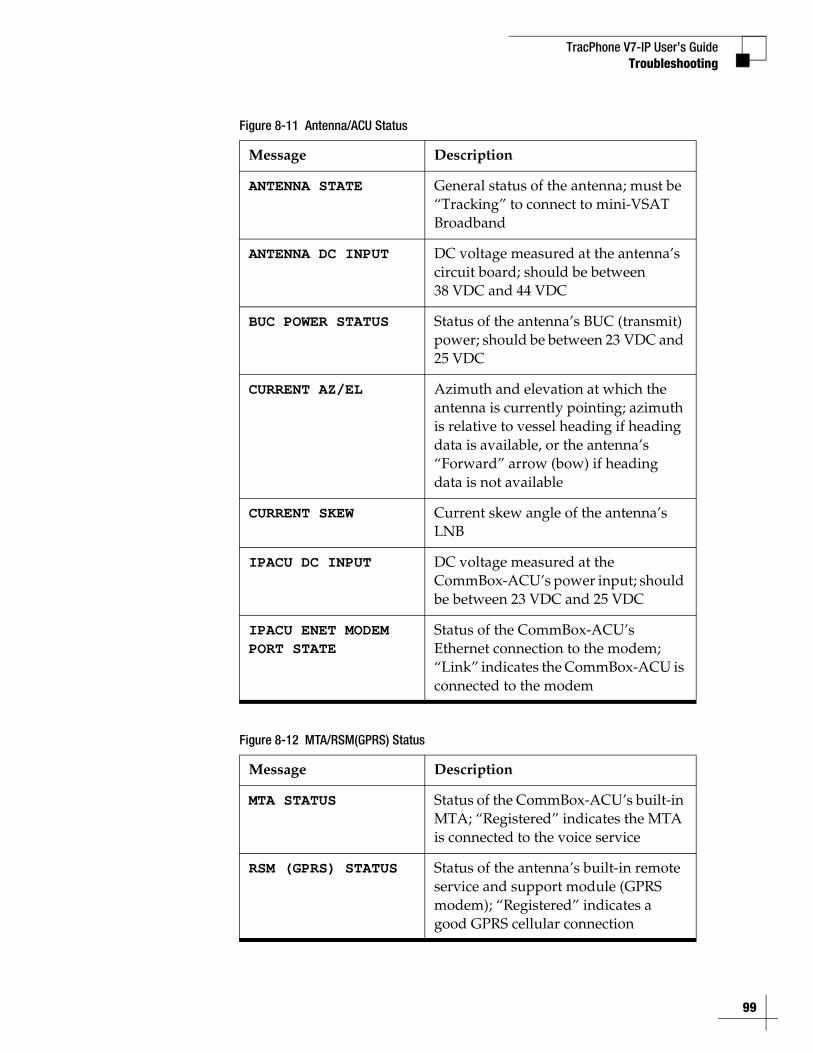
TracPhone V7-IP User’s GuideTroubleshooting
Figure 8-11 Antenna/ACU Status
Figure 8-12 MTA/RSM(GPRS) Status
Message Description
ANTENNA STATE General status of the antenna; must be “Tracking” to connect to mini-VSAT Broadband
ANTENNA DC INPUT DC voltage measured at the antenna’s circuit board; should be between 38 VDC and 44 VDC
BUC POWER STATUS Status of the antenna’s BUC (transmit) power; should be between 23 VDC and 25 VDC
CURRENT AZ/EL Azimuth and elevation at which the antenna is currently pointing; azimuth is relative to vessel heading if heading data is available, or the antenna’s “Forward” arrow (bow) if heading data is not available
CURRENT SKEW Current skew angle of the antenna’s LNB
IPACU DC INPUT DC voltage measured at the CommBox-ACU’s power input; should be between 23 VDC and 25 VDC
IPACU ENET MODEMPORT STATE
Status of the CommBox-ACU’s Ethernet connection to the modem; “Link” indicates the CommBox-ACU is connected to the modem
Message Description
MTA STATUS Status of the CommBox-ACU’s built-in MTA; “Registered” indicates the MTA is connected to the voice service
RSM (GPRS) STATUS Status of the antenna’s built-in remote service and support module (GPRS modem); “Registered” indicates a good GPRS cellular connection
99
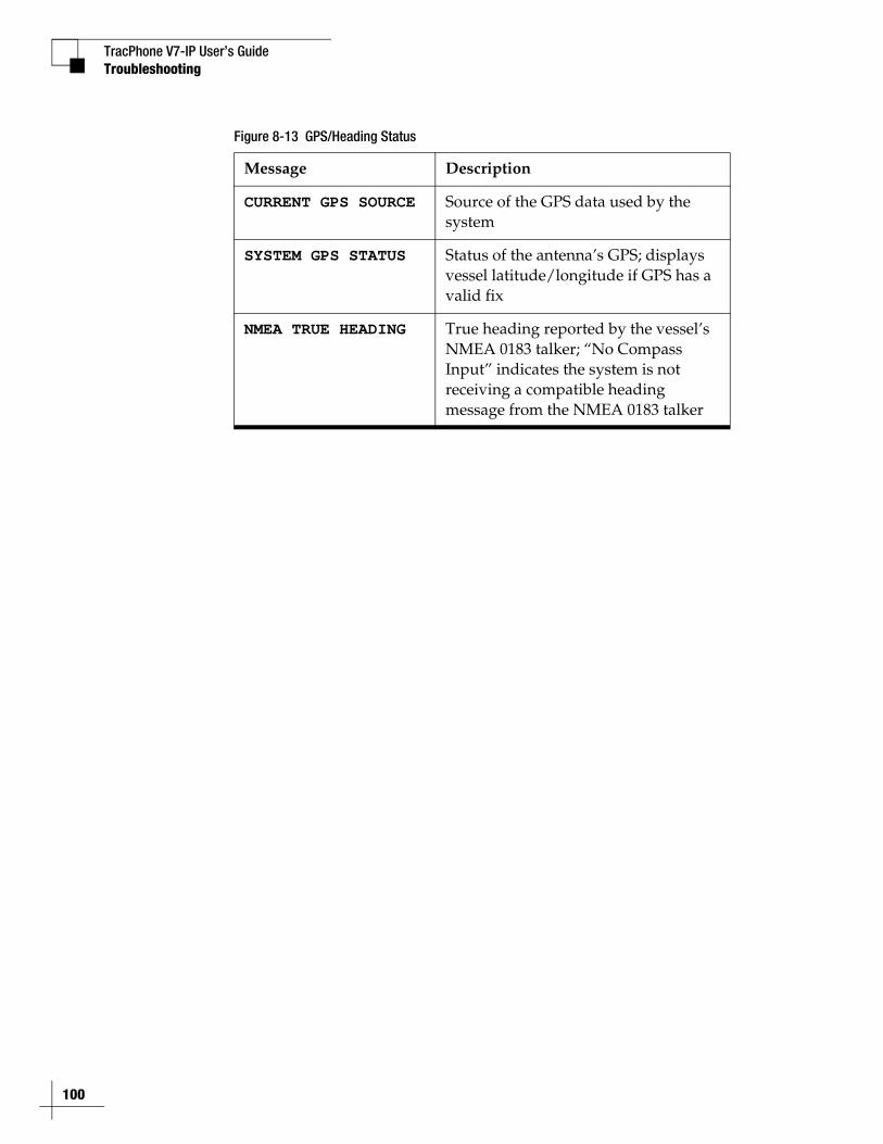
TracPhone V7-IP User’s Guide
100
Troubleshooting
Figure 8-13 GPS/Heading Status
Message Description
CURRENT GPS SOURCE Source of the GPS data used by the system
SYSTEM GPS STATUS Status of the antenna’s GPS; displays vessel latitude/longitude if GPS has a valid fix
NMEA TRUE HEADING True heading reported by the vessel’s NMEA 0183 talker; “No Compass Input” indicates the system is not receiving a compatible heading message from the NMEA 0183 talker
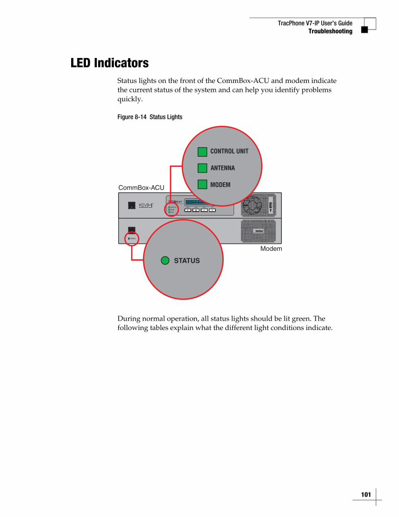
TracPhone V7-IP User’s GuideTroubleshooting
LED IndicatorsStatus lights on the front of the CommBox-ACU and modem indicate the current status of the system and can help you identify problems quickly.
Figure 8-14 Status Lights
During normal operation, all status lights should be lit green. The following tables explain what the different light conditions indicate.
STATUS
CommBox-ACU
Modem
101
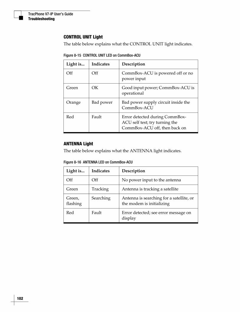
TracPhone V7-IP User’s Guide
102
Troubleshooting
CONTROL UNIT LightThe table below explains what the CONTROL UNIT light indicates.
Figure 8-15 CONTROL UNIT LED on CommBox-ACU
ANTENNA LightThe table below explains what the ANTENNA light indicates.
Figure 8-16 ANTENNA LED on CommBox-ACU
Light is... Indicates Description
Off Off CommBox-ACU is powered off or no power input
Green OK Good input power; CommBox-ACU is operational
Orange Bad power Bad power supply circuit inside the CommBox-ACU
Red Fault Error detected during CommBox-ACU self test; try turning the CommBox-ACU off, then back on
Light is... Indicates Description
Off Off No power input to the antenna
Green Tracking Antenna is tracking a satellite
Green, flashing
Searching Antenna is searching for a satellite, or the modem is initializing
Red Fault Error detected; see error message on display
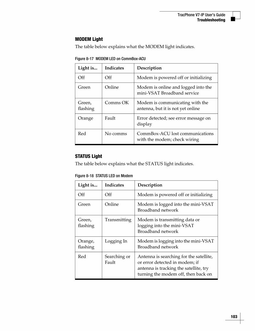
TracPhone V7-IP User’s GuideTroubleshooting
MODEM LightThe table below explains what the MODEM light indicates.
Figure 8-17 MODEM LED on CommBox-ACU
STATUS LightThe table below explains what the STATUS light indicates.
Figure 8-18 STATUS LED on Modem
Light is... Indicates Description
Off Off Modem is powered off or initializing
Green Online Modem is online and logged into the mini-VSAT Broadband service
Green, flashing
Comms OK Modem is communicating with the antenna, but it is not yet online
Orange Fault Error detected; see error message on display
Red No comms CommBox-ACU lost communications with the modem; check wiring
Light is... Indicates Description
Off Off Modem is powered off or initializing
Green Online Modem is logged into the mini-VSAT Broadband network
Green, flashing
Transmitting Modem is transmitting data or logging into the mini-VSAT Broadband network
Orange, flashing
Logging In Modem is logging into the mini-VSAT Broadband network
Red Searching or Fault
Antenna is searching for the satellite, or error detected in modem; if antenna is tracking the satellite, try turning the modem off, then back on
103
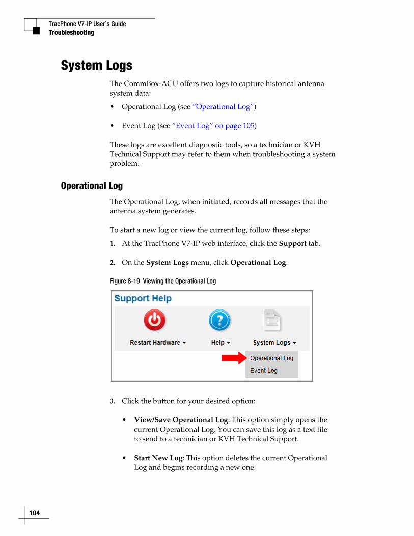
TracPhone V7-IP User’s Guide
104
Troubleshooting
System LogsThe CommBox-ACU offers two logs to capture historical antenna system data:
• Operational Log (see “Operational Log”)
• Event Log (see “Event Log” on page 105)
These logs are excellent diagnostic tools, so a technician or KVH Technical Support may refer to them when troubleshooting a system problem.
Operational Log
The Operational Log, when initiated, records all messages that the antenna system generates.
To start a new log or view the current log, follow these steps:
1. At the TracPhone V7-IP web interface, click the Support tab.
2. On the System Logs menu, click Operational Log.
Figure 8-19 Viewing the Operational Log
3. Click the button for your desired option:
• View/Save Operational Log: This option simply opens the current Operational Log. You can save this log as a text file to send to a technician or KVH Technical Support.
• Start New Log: This option deletes the current Operational Log and begins recording a new one.
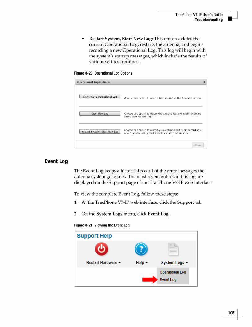
TracPhone V7-IP User’s GuideTroubleshooting
• Restart System, Start New Log: This option deletes the current Operational Log, restarts the antenna, and begins recording a new Operational Log. This log will begin with the system’s startup messages, which include the results of various self-test routines.
Figure 8-20 Operational Log Options
Event Log
The Event Log keeps a historical record of the error messages the antenna system generates. The most recent entries in this log are displayed on the Support page of the TracPhone V7-IP web interface.
To view the complete Event Log, follow these steps:
1. At the TracPhone V7-IP web interface, click the Support tab.
2. On the System Logs menu, click Event Log.
Figure 8-21 Viewing the Event Log
105
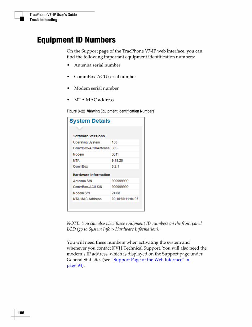
TracPhone V7-IP User’s Guide
106
Troubleshooting
Equipment ID NumbersOn the Support page of the TracPhone V7-IP web interface, you can find the following important equipment identification numbers:
• Antenna serial number
• CommBox-ACU serial number
• Modem serial number
• MTA MAC address
Figure 8-22 Viewing Equipment Identification Numbers
NOTE: You can also view these equipment ID numbers on the front panel LCD (go to System Info > Hardware Information).
You will need these numbers when activating the system and whenever you contact KVH Technical Support. You will also need the modem’s IP address, which is displayed on the Support page under General Statistics (see “Support Page of the Web Interface” on page 94).
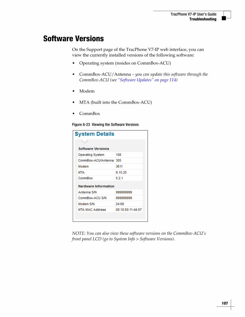
TracPhone V7-IP User’s GuideTroubleshooting
Software VersionsOn the Support page of the TracPhone V7-IP web interface, you can view the currently installed versions of the following software:
• Operating system (resides on CommBox-ACU)
• CommBox-ACU/Antenna – you can update this software through the CommBox-ACU (see “Software Updates” on page 114)
• Modem
• MTA (built into the CommBox-ACU)
• CommBox
Figure 8-23 Viewing the Software Versions
NOTE: You can also view these software versions on the CommBox-ACU’s front panel LCD (go to System Info > Software Versions).
107
TracPhone V7-IP User’s Guide
108
Troubleshooting
Technical SupportThe TracPhone V7-IP system is a sophisticated electronic device; only specially trained KVH-certified technicians have the tools and expertise necessary to diagnose and repair a system fault. Therefore, if you experience an operating problem or require technical assistance, please contact KVH Technical Support (24/7):
Within the Continental U.S.A.:Phone: 1 866 701-7103 E-mail: [email protected]
North/South America, Australia:Phone: +1 401 851-3806E-mail: [email protected]
Europe, Middle East, Asia, Africa:Phone: +45 45 160 180E-mail: [email protected]
Please have your system serial numbers and software versions handy before you call (see “Equipment ID Numbers” on page 106 and “Software Versions” on page 107).
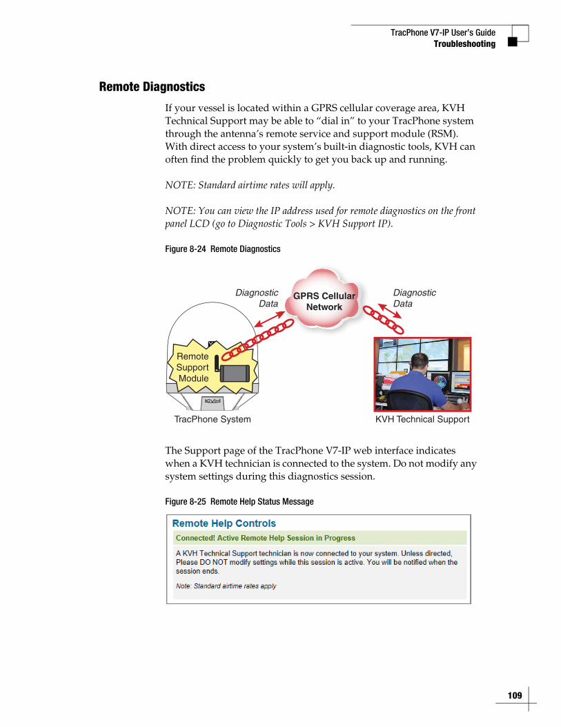
TracPhone V7-IP User’s GuideTroubleshooting
Remote Diagnostics
If your vessel is located within a GPRS cellular coverage area, KVH Technical Support may be able to “dial in” to your TracPhone system through the antenna’s remote service and support module (RSM). With direct access to your system’s built-in diagnostic tools, KVH can often find the problem quickly to get you back up and running.
NOTE: Standard airtime rates will apply.
NOTE: You can view the IP address used for remote diagnostics on the front panel LCD (go to Diagnostic Tools > KVH Support IP).
Figure 8-24 Remote Diagnostics
The Support page of the TracPhone V7-IP web interface indicates when a KVH technician is connected to the system. Do not modify any system settings during this diagnostics session.
Figure 8-25 Remote Help Status Message
TracPhone System KVH Technical Support
DiagnosticData
DiagnosticData
GPRS CellularNetwork
RemoteSupportModule
109
TracPhone V7-IP User’s Guide
111
Maintenance
9. MaintenanceThis section explains how to perform preventive maintenance to keep the system in tip-top shape. It also explains how to update the software and the modem’s satellite configuration files, calibrate the gyros, and restart system components.
ContentsPreventive Maintenance ................................................ 113
Software Updates .......................................................... 114
Modem Configuration Updates ...................................... 119
Corrective Maintenance................................................. 124
Gyro Calibration ............................................................. 125
Hardware Restart .......................................................... 127
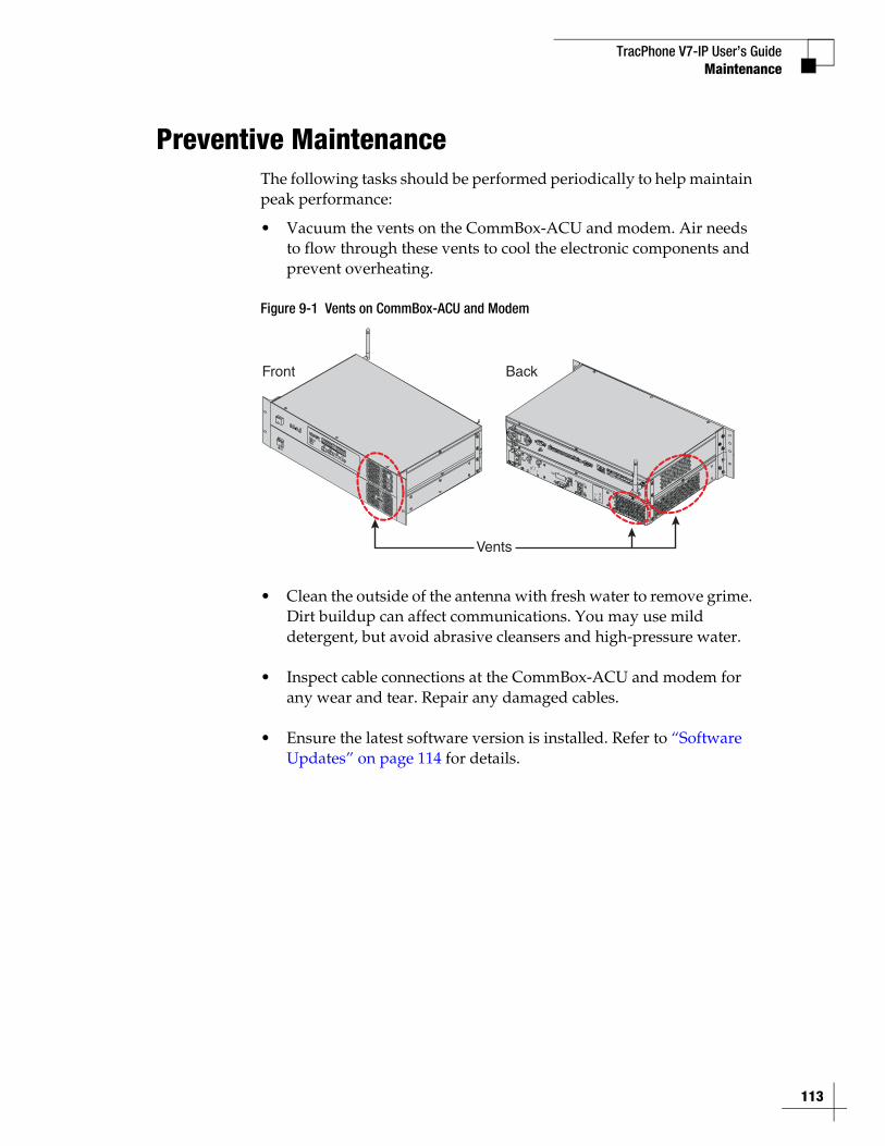
TracPhone V7-IP User’s Guide
113
Maintenance
Preventive MaintenanceThe following tasks should be performed periodically to help maintain peak performance:
• Vacuum the vents on the CommBox-ACU and modem. Air needs to flow through these vents to cool the electronic components and prevent overheating.
Figure 9-1 Vents on CommBox-ACU and Modem
• Clean the outside of the antenna with fresh water to remove grime. Dirt buildup can affect communications. You may use mild detergent, but avoid abrasive cleansers and high-pressure water.
• Inspect cable connections at the CommBox-ACU and modem for any wear and tear. Repair any damaged cables.
• Ensure the latest software version is installed. Refer to “Software Updates” on page 114 for details.
Front Back
Vents
TracPhone V7-IP User’s Guide
114
Maintenance
Software UpdatesKVH periodically releases new versions of software to enhance the performance and capabilities of the system. You can update your system to this latest software at any time by downloading the file from KVH’s Update server and uploading it to the CommBox-ACU. When you update the software, the new version simply overwrites the previously installed version.
A single software package includes updates to all system components in the antenna and CommBox-ACU. Modem updates are downloaded to the modem automatically via the satellite connection.
There are several methods to choose from to update the software:
• “Using the CommBox-ACU to Update Software”
• “Using Your Computer to Update Software” on page 116
• “Using an iPhone/iPod touch to Update Software” on page 117
• “Using a USB Flash Drive to Update Software” on page 118
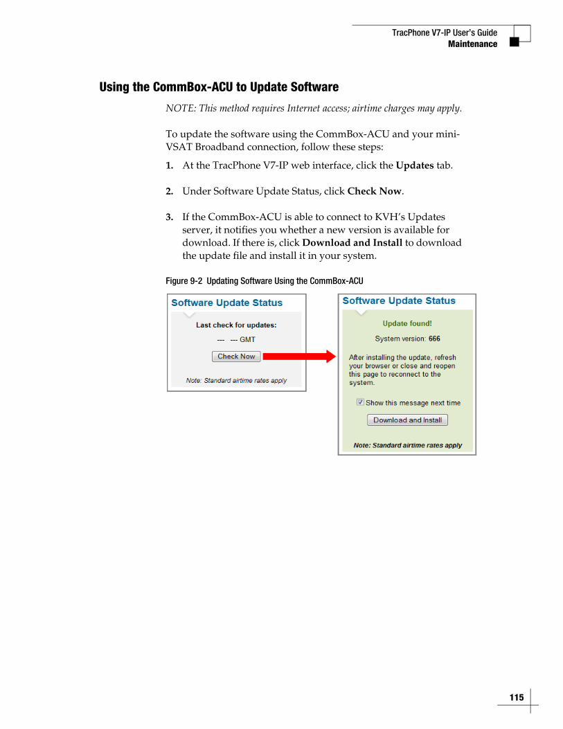
TracPhone V7-IP User’s GuideMaintenance
Using the CommBox-ACU to Update Software
NOTE: This method requires Internet access; airtime charges may apply.
To update the software using the CommBox-ACU and your mini-VSAT Broadband connection, follow these steps:
1. At the TracPhone V7-IP web interface, click the Updates tab.
2. Under Software Update Status, click Check Now.
3. If the CommBox-ACU is able to connect to KVH’s Updates server, it notifies you whether a new version is available for download. If there is, click Download and Install to download the update file and install it in your system.
Figure 9-2 Updating Software Using the CommBox-ACU
115
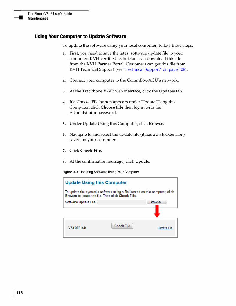
TracPhone V7-IP User’s Guide
116
Maintenance
Using Your Computer to Update Software
To update the software using your local computer, follow these steps:
1. First, you need to save the latest software update file to your computer. KVH-certified technicians can download this file from the KVH Partner Portal. Customers can get this file from KVH Technical Support (see “Technical Support” on page 108).
2. Connect your computer to the CommBox-ACU’s network.
3. At the TracPhone V7-IP web interface, click the Updates tab.
4. If a Choose File button appears under Update Using this Computer, click Choose File then log in with the Administrator password.
5. Under Update Using this Computer, click Browse.
6. Navigate to and select the update file (it has a .kvh extension) saved on your computer.
7. Click Check File.
8. At the confirmation message, click Update.
Figure 9-3 Updating Software Using Your Computer
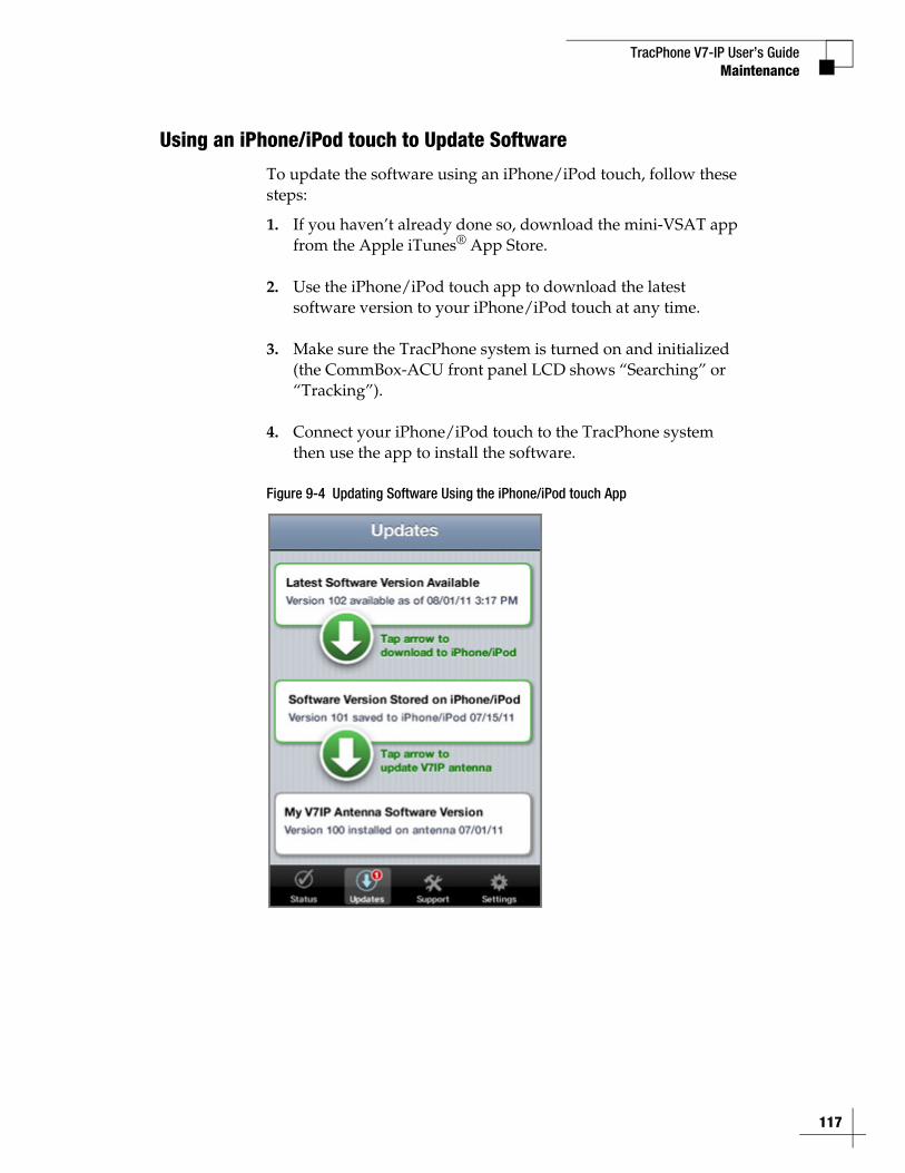
TracPhone V7-IP User’s GuideMaintenance
Using an iPhone/iPod touch to Update Software
To update the software using an iPhone/iPod touch, follow these steps:
1. If you haven’t already done so, download the mini-VSAT app from the Apple iTunes® App Store.
2. Use the iPhone/iPod touch app to download the latest software version to your iPhone/iPod touch at any time.
3. Make sure the TracPhone system is turned on and initialized (the CommBox-ACU front panel LCD shows “Searching” or “Tracking”).
4. Connect your iPhone/iPod touch to the TracPhone system then use the app to install the software.
Figure 9-4 Updating Software Using the iPhone/iPod touch App
117
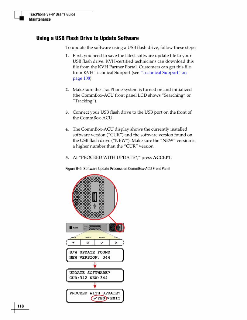
TracPhone V7-IP User’s Guide
118
Maintenance
Using a USB Flash Drive to Update Software
To update the software using a USB flash drive, follow these steps:
1. First, you need to save the latest software update file to your USB flash drive. KVH-certified technicians can download this file from the KVH Partner Portal. Customers can get this file from KVH Technical Support (see “Technical Support” on page 108).
2. Make sure the TracPhone system is turned on and initialized (the CommBox-ACU front panel LCD shows “Searching” or “Tracking”).
3. Connect your USB flash drive to the USB port on the front of the CommBox-ACU.
4. The CommBox-ACU display shows the currently installed software version (“CUR”) and the software version found on the USB flash drive (“NEW”). Make sure the “NEW” version is a higher number than the “CUR” version.
5. At “PROCEED WITH UPDATE?,” press ACCEPT.
Figure 9-5 Software Update Process on CommBox-ACU Front Panel
S/W UPDATE FOUNDNEW VERSION: 344
UPDATE SOFTWARE?CUR:342 NEW:344
PROCEED WITH UPDATE? YES EXIT
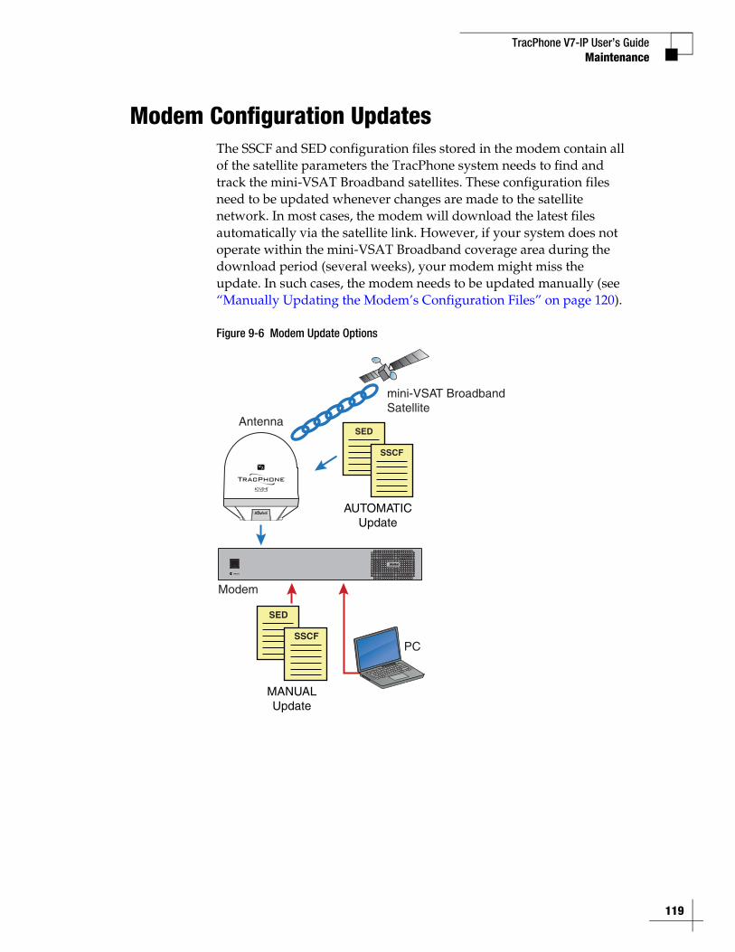
TracPhone V7-IP User’s Guide
119
Maintenance
Modem Configuration UpdatesThe SSCF and SED configuration files stored in the modem contain all of the satellite parameters the TracPhone system needs to find and track the mini-VSAT Broadband satellites. These configuration files need to be updated whenever changes are made to the satellite network. In most cases, the modem will download the latest files automatically via the satellite link. However, if your system does not operate within the mini-VSAT Broadband coverage area during the download period (several weeks), your modem might miss the update. In such cases, the modem needs to be updated manually (see “Manually Updating the Modem’s Configuration Files” on page 120).
Figure 9-6 Modem Update Options
Modem
AntennaSED
SSCF
mini-VSAT BroadbandSatellite
SED
SSCF
AUTOMATICUpdate
MANUALUpdate
PC
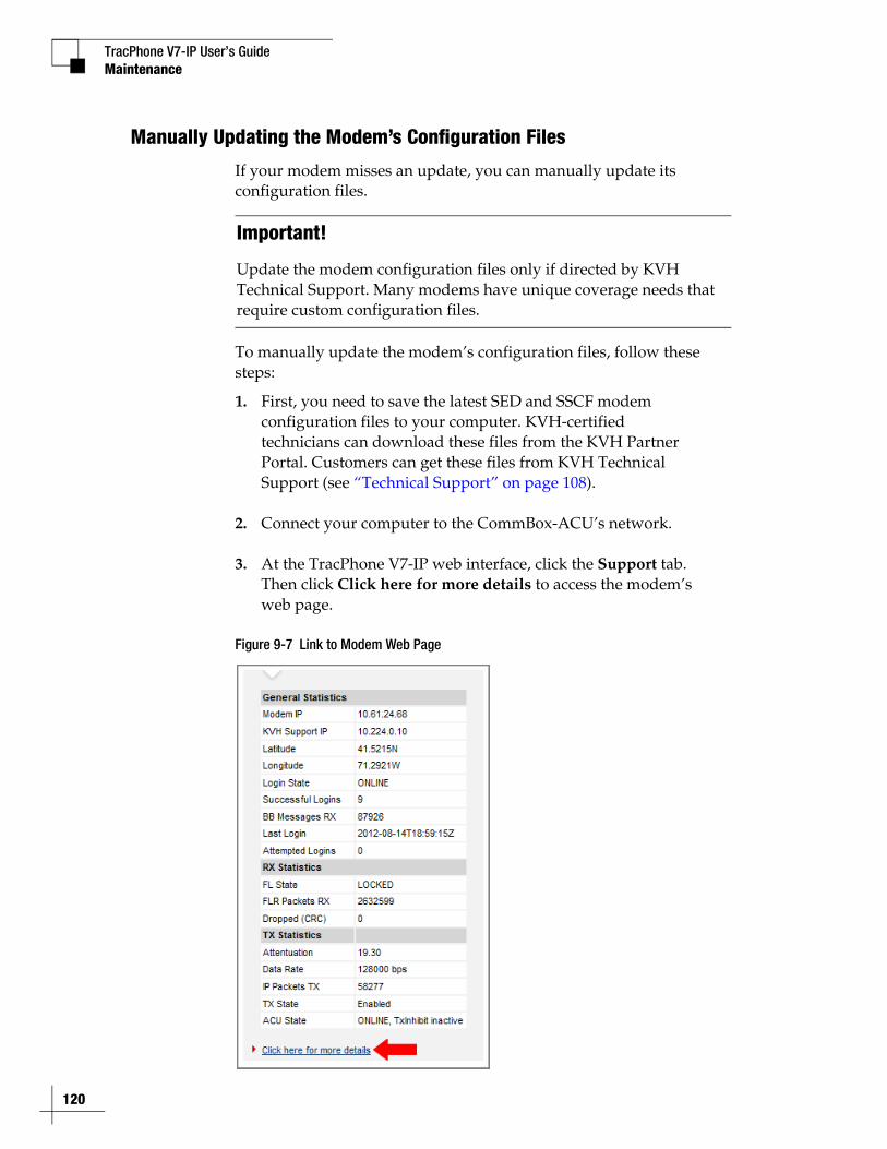
TracPhone V7-IP User’s Guide
120
Maintenance
Manually Updating the Modem’s Configuration Files
If your modem misses an update, you can manually update its configuration files.
To manually update the modem’s configuration files, follow these steps:
1. First, you need to save the latest SED and SSCF modem configuration files to your computer. KVH-certified technicians can download these files from the KVH Partner Portal. Customers can get these files from KVH Technical Support (see “Technical Support” on page 108).
2. Connect your computer to the CommBox-ACU’s network.
3. At the TracPhone V7-IP web interface, click the Support tab. Then click Click here for more details to access the modem’s web page.
Figure 9-7 Link to Modem Web Page
Important!
Update the modem configuration files only if directed by KVH Technical Support. Many modems have unique coverage needs that require custom configuration files.
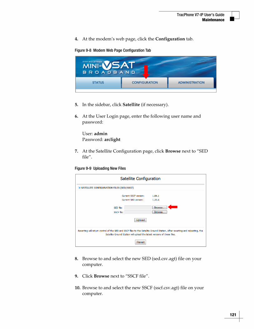
TracPhone V7-IP User’s GuideMaintenance
4. At the modem’s web page, click the Configuration tab.
Figure 9-8 Modem Web Page Configuration Tab
5. In the sidebar, click Satellite (if necessary).
6. At the User Login page, enter the following user name and password:
User: adminPassword: arclight
7. At the Satellite Configuration page, click Browse next to “SED file”.
Figure 9-9 Uploading New Files
8. Browse to and select the new SED (sed.csv.agt) file on your computer.
9. Click Browse next to “SSCF file”.
10. Browse to and select the new SSCF (sscf.csv.agt) file on your computer.
121

TracPhone V7-IP User’s Guide
122
Maintenance
11. Click Upload. Make sure the new versions appear under the old versions.
12. Click Save files.
Figure 9-10 Saving the New Files to the Modem
13. When the “Files saved” message appears, click Revert.
Important!
Be sure to revert control of SSCF and SED files to the Satellite Ground Station, allowing the modem to receive future automatic updates via the satellite link.
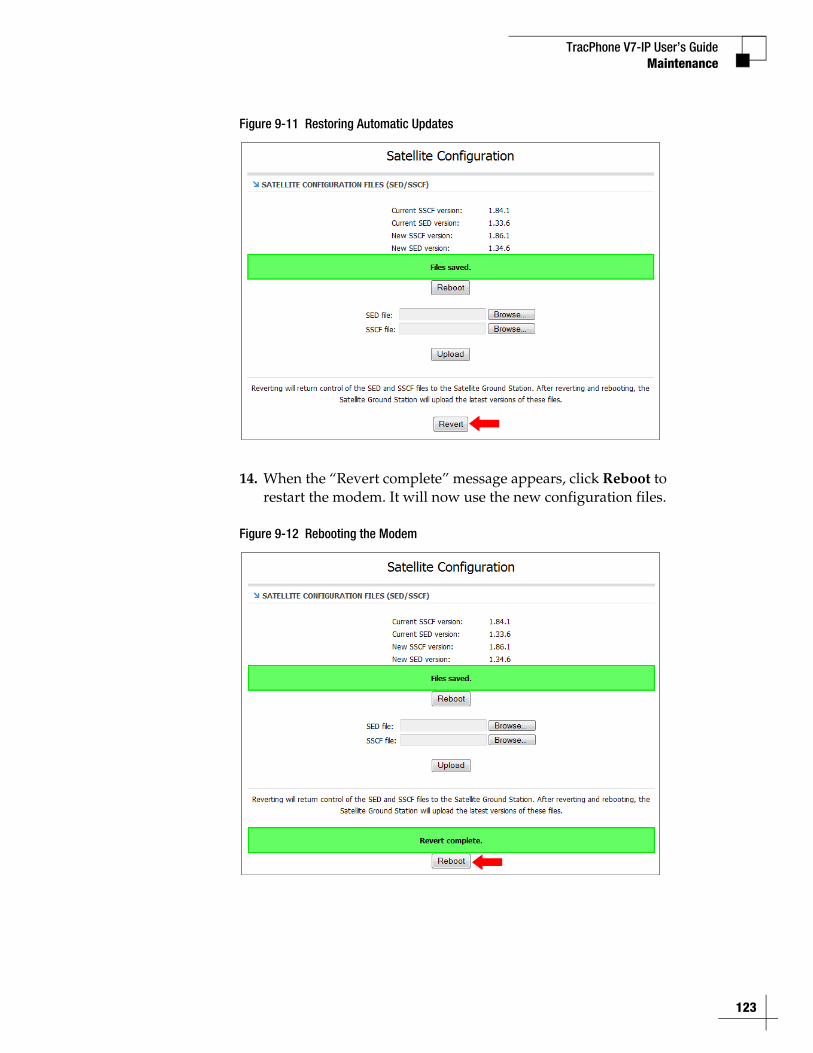
TracPhone V7-IP User’s GuideMaintenance
Figure 9-11 Restoring Automatic Updates
14. When the “Revert complete” message appears, click Reboot to restart the modem. It will now use the new configuration files.
Figure 9-12 Rebooting the Modem
123
TracPhone V7-IP User’s Guide
124
Maintenance
Corrective MaintenanceIf a system component fails, it will need to be replaced by a KVH-certified technician.
The antenna contains several parts that can be replaced in the field by a KVH-certified technician. Instructions for replacing these parts are provided with the replacement part.
The belowdecks equipment has no field replaceable units. If the CommBox-ACU or modem becomes damaged, the entire device will need to be replaced.
Important!
Field replaceable units should only be replaced by a trained, KVH-certified technician. To find a technician near you, visit www.kvh.com/wheretogetservice or contact KVH Technical Support (see “Technical Support” on page 108).
Important!
Do not open the CommBox-ACU or modem chassis for any reason. Any evidence of tampering will void its warranty.
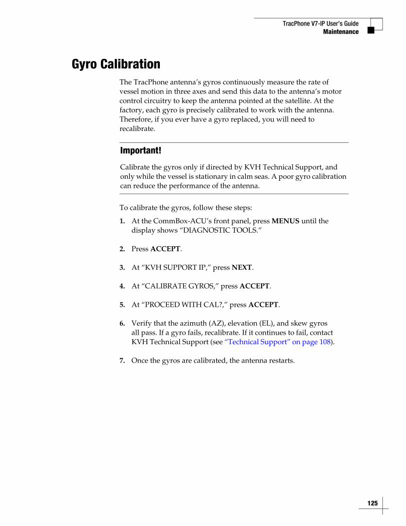
TracPhone V7-IP User’s Guide
125
Maintenance
Gyro CalibrationThe TracPhone antenna’s gyros continuously measure the rate of vessel motion in three axes and send this data to the antenna’s motor control circuitry to keep the antenna pointed at the satellite. At the factory, each gyro is precisely calibrated to work with the antenna. Therefore, if you ever have a gyro replaced, you will need to recalibrate.
To calibrate the gyros, follow these steps:
1. At the CommBox-ACU’s front panel, press MENUS until the display shows “DIAGNOSTIC TOOLS.”
2. Press ACCEPT.
3. At “KVH SUPPORT IP,” press NEXT.
4. At “CALIBRATE GYROS,” press ACCEPT.
5. At “PROCEED WITH CAL?,” press ACCEPT.
6. Verify that the azimuth (AZ), elevation (EL), and skew gyros all pass. If a gyro fails, recalibrate. If it continues to fail, contact KVH Technical Support (see “Technical Support” on page 108).
7. Once the gyros are calibrated, the antenna restarts.
Important!
Calibrate the gyros only if directed by KVH Technical Support, and only while the vessel is stationary in calm seas. A poor gyro calibration can reduce the performance of the antenna.
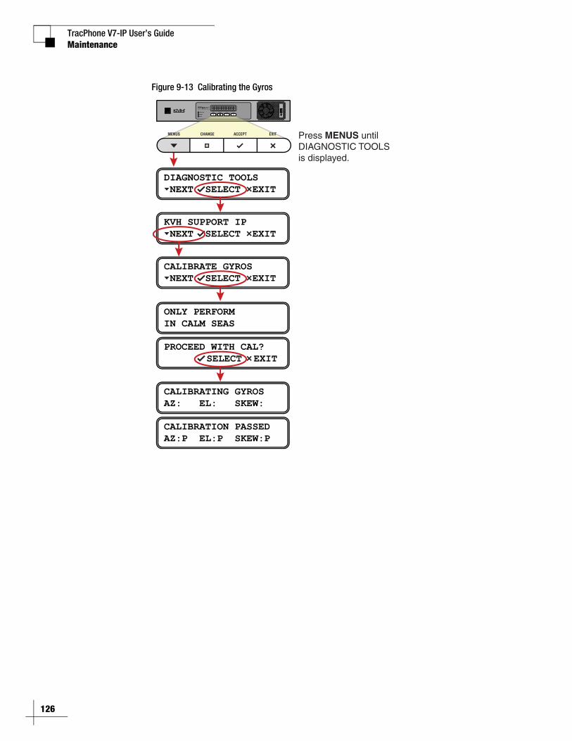
TracPhone V7-IP User’s Guide
126
Maintenance
Figure 9-13 Calibrating the Gyros
DIAGNOSTIC TOOLS NEXT SELECT EXIT
KVH SUPPORT IP NEXT SELECT EXIT
CALIBRATE GYROS NEXT SELECT EXIT
ONLY PERFORMIN CALM SEAS
PROCEED WITH CAL? SELECT EXIT
CALIBRATING GYROSAZ: EL: SKEW:
CALIBRATION PASSEDAZ:P EL:P SKEW:P
Press MENUS until DIAGNOSTIC TOOLS is displayed.
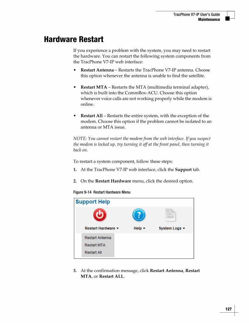
TracPhone V7-IP User’s GuideMaintenance
Hardware RestartIf you experience a problem with the system, you may need to restart the hardware. You can restart the following system components from the TracPhone V7-IP web interface:
• Restart Antenna – Restarts the TracPhone V7-IP antenna. Choose this option whenever the antenna is unable to find the satellite.
• Restart MTA – Restarts the MTA (multimedia terminal adapter), which is built into the CommBox-ACU. Choose this option whenever voice calls are not working properly while the modem is online.
• Restart All – Restarts the entire system, with the exception of the modem. Choose this option if the problem cannot be isolated to an antenna or MTA issue.
NOTE: You cannot restart the modem from the web interface. If you suspect the modem is locked up, try turning it off at the front panel, then turning it back on.
To restart a system component, follow these steps:
1. At the TracPhone V7-IP web interface, click the Support tab.
2. On the Restart Hardware menu, click the desired option.
Figure 9-14 Restart Hardware Menu
3. At the confirmation message, click Restart Antenna, Restart MTA, or Restart ALL.
127

TracPhone V7-IP User’s Guide
129
Wiring Diagram
AppendixA. Wiring Diagram
This section provides a system wiring diagram. For detailed installation instructions, refer to the Installation Guide.
ContentsWiring Diagram.............................................................. 131

TracPhone V7-IP User’s Guide
131
Wiring Diagram
Wiring DiagramThe wiring diagram below shows the basic system connections. For detailed installation instructions, refer to the Installation Guide.
Power
Power
J1AC PWR
J3Rx RF
J2Tx RF
J4ACU
J5CONSOLE
J6BUC PWR J8
USERENET
J7ACUENET
NO OPERATORSERVICEABLEPARTS INSIDE,DO NOT OPEN
CAUTION
MODEL: VMBR-1510 ArcLightPART: 1234567 REV XXXSERIAL: XX-XXXXXXCAGE CODE: 12345
AC Input100-240V; 1.6-0.8A 50/60 Hz
MaintenanceRS232
To ModemRS422
NMEA
1 2 0
WiFi
1 2 3 4Voice Lines (Analog) User Ethernet PortsEthernet
Red
(+48
V)
Blac
k (G
nd)
Whi
te/G
ray
Gray
/Whi
te
Whi
te/O
rang
e
Oran
ge/W
hite
Whi
te/B
row
n
Brow
n/W
hite
Whi
te/B
lue
Blue
/Whi
te
Whi
te/G
reen
Gree
n/W
hite
Red/
Oran
ge
Oran
ge/R
ed
Red/
Gree
n
Gree
n/Re
d
B A
To Modem
Manufactured in USA.
BUC Power24VDC , 2.5AKVH and TracPhone are registered trademarks
of KVH Industries, Inc.; mini-VSAT Broadband is a service mark of KVH Industries, Inc.
Tested to comply with FCC Standards
CAUTIONRISK OF ELECTRIC SHOCK
DO NOT OPEN
1000
Fuse 3A, 250V ~ Fast Acting N
1 2 11109876 12543 13 14 15 16
Antenna
CommBox-ACU
MTx
MRx
Modem
Blue/White
White/Blue
Brown/White
White/Gray
Gray/White
White/Orange
Orange/White
White/Brown
Red
Black
Terminal Strip Connectors
Vessel PC
Vessel Phone
NMEA 0183 Talker(customer-supplied)
Power/Data
TxRFRxRF
1 2
A
B
Ship’s Heading
User Enet
BUC Pwr
ACU
Orange/Red
Red/OrangeGreen/White
White/Green
To Modem Ethernet 0
BUC PowerVoiceLine 1
UserEthernet 1
To Antenna NMEA
43 V
DC
Com
mon
Por
t 1, T
xD+
Por
t 1, T
xD-
Por
t 1, R
xD+
Por
t 2, T
xD+
Por
t 1, R
xD-
Por
t 2, T
xD-
Por
t 2, R
xD+
Por
t 2, R
xD-
GP
RS
, TxD
+
GP
RS
, TxD
-
GP
RS
, RxD
+
GP
RS
, RxD
-
Ground
N/C
Two unused wires are reserved for future use; N/C = Not Connected
N/C

TracPhone V7-IP User’s Guide
133
LCD Menus
AppendixB. LCD Menus
This section provides a quick reference guide to the LCD menus on the CommBox-ACU’s front panel.
ContentsLCD Menus Quick Reference Guide ............................... 135
TracPhone V7-IP User’s Guide
135
LCD Menus
LCD Menus Quick Reference GuideThe chart below shows the menu structure of the CommBox-ACU front panel LCD interface.
KVH Support IPCalibrate GyrosFactory Reset
Software VersionsCommBox-ACU OSCommBox-ACU AppModemMTA
Hardware InformationAntenna ModelAntenna S/NCommBox-ACU S/NModem S/NMTA MAC Address
Ignoring Zones (if applicable)Transmit Enabled/Disabled (if applicable)No-Transmit Zone 1 Range (if applicable)No-Transmit Zone 2 Range (if applicable)
System SettingsLCD Brightness
Network SettingsIP AssignmentsPort Assignments
STATUS NEXT SELECT EXIT
SETTINGS NEXT SELECT EXIT
NO-TRANSMIT ZONES NEXT SELECT EXIT
SYSTEM INFO NEXT SELECT EXIT
DIAGNOSTIC TOOLS NEXT SELECT EXIT
Modem/Network StatusModem Satellite IPModem StateLAN Port StatusEb/NoSatelliteBeamDownlink FrequencySkew to Satellite
Antenna/ACU StatusAntenna StateAntenna DC InputBUC Power StatusCurrent Az/ElCurrent SkewIPACU DC InputIPACU ENet Modem Port State
MTA/RSM (GPRS)MTA StatusRSM (GPRS) Status
GPS/Heading StatusCurrent GPS SourceSystem GPS StatusNMEA True Heading

TracPhone V7-IP User’s Guide
137
Regulatory Approvals
AppendixC. Regulatory Approvals
This section provides the CE declaration of conformity for the TracPhone V7-IP system components.
ContentsCE Declaration of Conformity......................................... 139
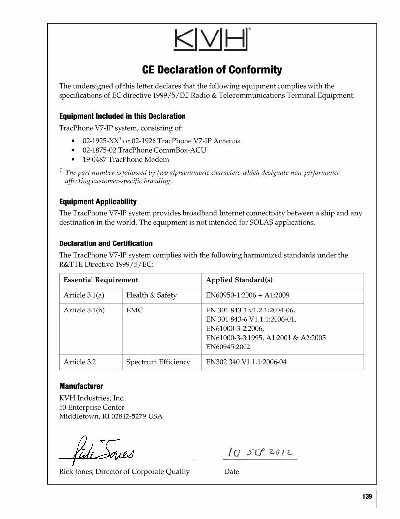
139
CE Declaration of ConformityThe undersigned of this letter declares that the following equipment complies with the specifications of EC directive 1999/5/EC Radio & Telecommunications Terminal Equipment.
Equipment Included in this DeclarationTracPhone V7-IP system, consisting of:
• 02-1925-XX1 or 02-1926 TracPhone V7-IP Antenna• 02-1875-02 TracPhone CommBox-ACU• 19-0487 TracPhone Modem
1 The part number is followed by two alphanumeric characters which designate non-performance-affecting customer-specific branding.
Equipment ApplicabilityThe TracPhone V7-IP system provides broadband Internet connectivity between a ship and any destination in the world. The equipment is not intended for SOLAS applications.
Declaration and CertificationThe TracPhone V7-IP system complies with the following harmonized standards under the R&TTE Directive 1999/5/EC:
ManufacturerKVH Industries, Inc.50 Enterprise CenterMiddletown, RI 02842-5279 USA
Rick Jones, Director of Corporate Quality Date
Essential Requirement Applied Standard(s)
Article 3.1(a) Health & Safety EN60950-1:2006 + A1:2009
Article 3.1(b) EMC EN 301 843-1 v1.2.1:2004-06, EN 301 843-6 V1.1.1:2006-01, EN61000-3-2:2006, EN61000-3-3:1995, A1:2001 & A2:2005EN60945:2002
Article 3.2 Spectrum Efficiency EN302 340 V1.1.1:2006-04

TracPhone V7-IP User’s Guide
141
Specifications
AppendixD. Specifications
This section provides the technical specifications of the TracPhone system’s components.
ContentsSystem Specifications ................................................... 143
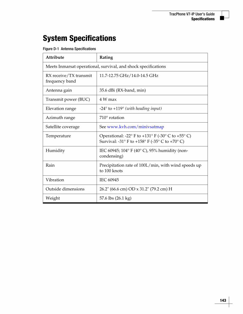
TracPhone V7-IP User’s Guide
143
Specifications
System SpecificationsFigure D-1 Antenna Specifications
Attribute Rating
Meets Inmarsat operational, survival, and shock specifications
RX receive/TX transmit frequency band
11.7-12.75 GHz/14.0-14.5 GHz
Antenna gain 35.6 dBi (RX-band, min)
Transmit power (BUC) 4 W max
Elevation range -24° to +119° (with heading input)
Azimuth range 710° rotation
Satellite coverage See www.kvh.com/minivsatmap
Temperature Operational: -22° F to +131° F (-30° C to +55° C) Survival: -31° F to +158° F (-35° C to +70° C)
Humidity IEC 60945; 104° F (40° C), 95% humidity (non-condensing)
Rain Precipitation rate of 100L/min, with wind speeds up to 100 knots
Vibration IEC 60945
Outside dimensions 26.2" (66.6 cm) OD x 31.2" (79.2 cm) H
Weight 57.6 lbs (26.1 kg)
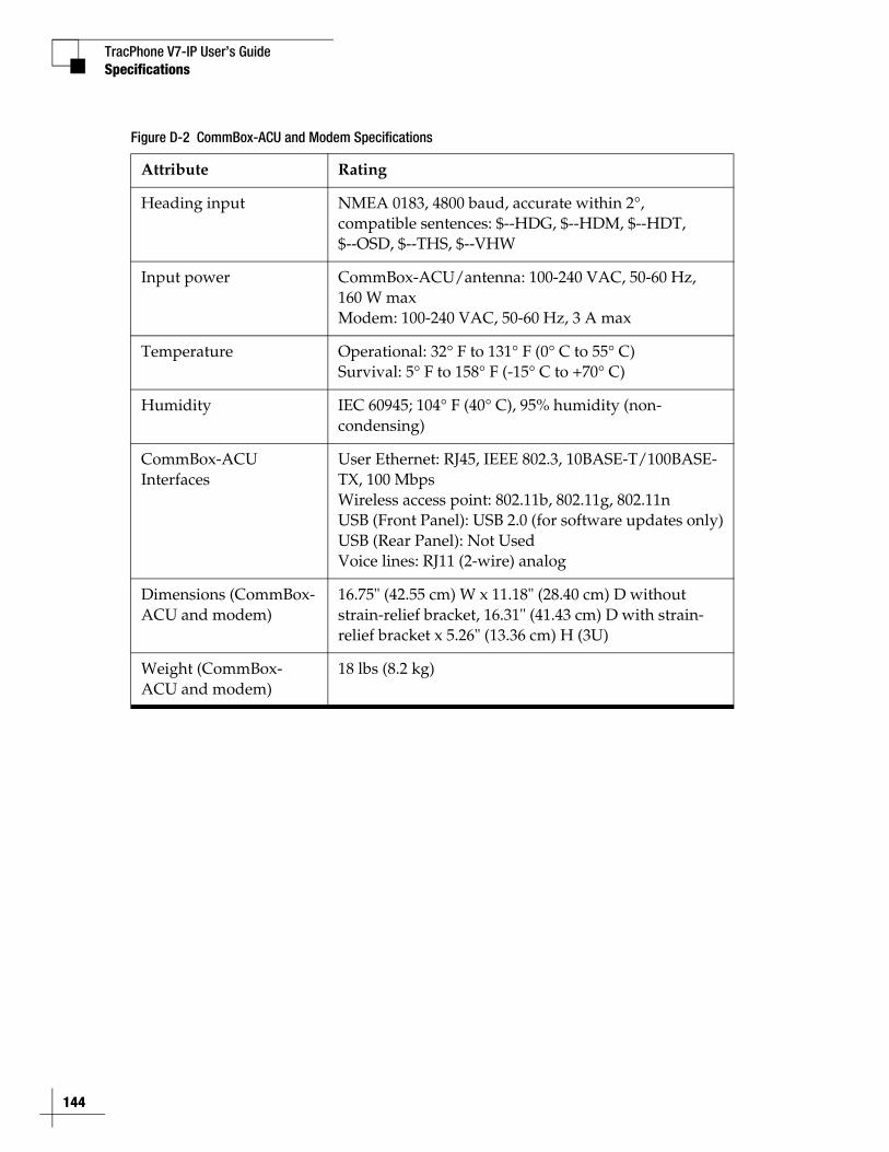
TracPhone V7-IP User’s Guide
144
Specifications
Figure D-2 CommBox-ACU and Modem Specifications
Attribute Rating
Heading input NMEA 0183, 4800 baud, accurate within 2°, compatible sentences: $--HDG, $--HDM, $--HDT, $--OSD, $--THS, $--VHW
Input power CommBox-ACU/antenna: 100-240 VAC, 50-60 Hz, 160 W maxModem: 100-240 VAC, 50-60 Hz, 3 A max
Temperature Operational: 32° F to 131° F (0° C to 55° C)Survival: 5° F to 158° F (-15° C to +70° C)
Humidity IEC 60945; 104° F (40° C), 95% humidity (non-condensing)
CommBox-ACU Interfaces
User Ethernet: RJ45, IEEE 802.3, 10BASE-T/100BASE-TX, 100 MbpsWireless access point: 802.11b, 802.11g, 802.11nUSB (Front Panel): USB 2.0 (for software updates only)USB (Rear Panel): Not UsedVoice lines: RJ11 (2-wire) analog
Dimensions (CommBox-ACU and modem)
16.75" (42.55 cm) W x 11.18" (28.40 cm) D without strain-relief bracket, 16.31" (41.43 cm) D with strain-relief bracket x 5.26" (13.36 cm) H (3U)
Weight (CommBox-ACU and modem)
18 lbs (8.2 kg)

TracPhone V7-IP User’s Guide
145
Glossary
AppendixE. Glossary
This section provides a glossary of technical terms used throughout the documentation.
ContentsGlossary......................................................................... 147
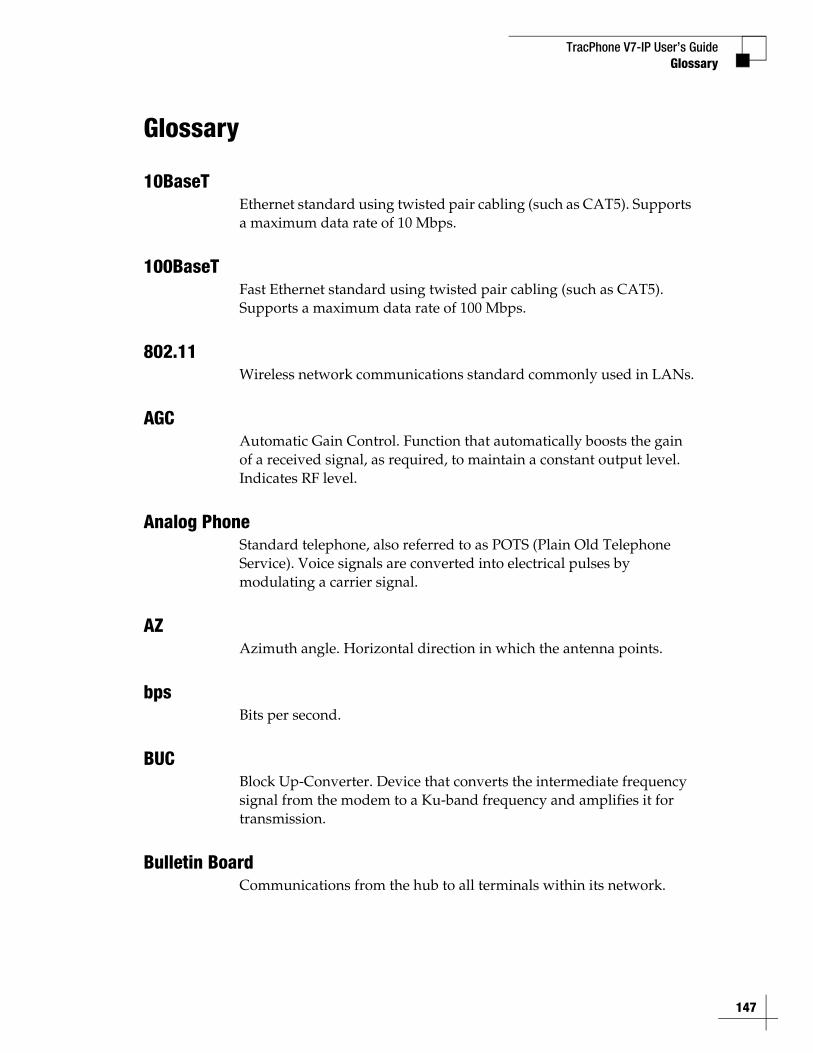
TracPhone V7-IP User’s GuideGlossary
Glossary
10BaseTEthernet standard using twisted pair cabling (such as CAT5). Supports a maximum data rate of 10 Mbps.
100BaseTFast Ethernet standard using twisted pair cabling (such as CAT5). Supports a maximum data rate of 100 Mbps.
802.11Wireless network communications standard commonly used in LANs.
AGCAutomatic Gain Control. Function that automatically boosts the gain of a received signal, as required, to maintain a constant output level. Indicates RF level.
Analog PhoneStandard telephone, also referred to as POTS (Plain Old Telephone Service). Voice signals are converted into electrical pulses by modulating a carrier signal.
AZAzimuth angle. Horizontal direction in which the antenna points.
bpsBits per second.
BUCBlock Up-Converter. Device that converts the intermediate frequency signal from the modem to a Ku-band frequency and amplifies it for transmission.
Bulletin BoardCommunications from the hub to all terminals within its network.
147
TracPhone V7-IP User’s Guide
148
Glossary
CacheA web browser's local storage of visited web pages and other Internet files, allowing that information to be accessed more quickly on subsequent visits.
CAT5Category of twisted pair cable with a maximum data rate of 1,000 Mbps.
ChannelFrequency (between 2.4-2.5 GHz) used for Wi-Fi communications. To communicate via a wireless connection, both router and host must be set to the same channel. There are 11 channels to choose from, allowing users to prevent interference between multiple wireless networks.
ChassisThe outside enclosure of an electronic device.
ClientA computer application that accesses resources held by a server.
CRMACode Reuse Multiple Access (CRMA) protocol is a variant of CDMA, which is widely used in cellular communications. Using this protocol, multiple vessels share bandwidth for ship-to-shore transmissions to the satellite. Unlike TDMA, vessels don’t need to wait their turn to transmit. They can immediately transmit in bursts at the same time as other vessels and at the fastest data rate available, significantly reducing delays.
Crossover CableCable in which the pins are reversed from one end to the other. Used for connecting two computers back-to-back without using an Ethernet hub.
Data RateSpeed at which a communications path can transfer information, normally measured in bits per second (bps).
TracPhone V7-IP User’s GuideGlossary
dBDecibel. Ratio of one power level to another.
DHCPDynamic Host Configuration Protocol. IP protocol that allows a server to automatically assign IP addressing information to a computer or device on the network.
DNSDomain Name Service. IP service that translates domain names (such as “www.kvh.com”) into IP addresses (such as “63.105.58.10”).
DownlinkCommunication path from the satellite to the antenna.
DVBDigital Video Broadcasting project. Global standard of digital broadcasts.
Eb/NoRatio of Energy-per-bit to Noise power spectral density, indicating the general quality of a received signal.
EIRPEffective Isotropic Radiated Power, measured in dBW.
ELElevation angle. Vertical direction in which the antenna points.
EncryptionAs it applies to Wi-Fi, encoding of a wireless signal to protect it from unauthorized reception.
EthernetNetwork communications standard adopted by most LANs. Communicates via twisted pair cable at one of three maximum data rates: (1) Standard - 10 Mbps, (2) Fast - 100 Mbps, and (3) Gigabit - 1 Gbps (1,000 Mbps).
149
TracPhone V7-IP User’s Guide
150
Glossary
FirewallSecurity mechanism that protects a network from unauthorized access.
Floating GroundDangerous condition in which the chassis ground of an electrical device differs from ship’s ground. This difference can measure well over 100 volts, risking damage to the equipment and electric shock, potentially resulting in death. A floating ground can be prevented by ensuring proper grounding of the device to ship’s ground.
FootprintCoverage area of a satellite.
Forward LinkCommunication path from the satellite hub to the user terminal. Another term for “Downlink.”
FrequencyNumber of cycles per second of a radio wave, measured in Hertz (Hz).
GPRSGeneral Packet Radio Service. High-speed wireless data communications standard.
GPSGlobal Positioning System. Network of satellites that allow anyone with a GPS device to accurately fix their position on Earth.
GyroA device that precisely senses and measures motion in a single axis, such as elevation or azimuth.
HostAny computer connected to a network.
HTTPHyperText Transfer Protocol. The primary protocol for the World Wide Web.
TracPhone V7-IP User’s GuideGlossary
HubEarth station that links the satellite network to the terrestrial network.
IFIntermediate Frequency. As it applies to TracPhone V7-IP, L-band output of an LNB, or input to a BUC.
IMAPInternet Message Access Protocol. E-mail protocol by which a client retrieves user-selected messages that are stored on a remote mail server. Messages are saved on the server until the user deletes them.
InternetGlobal network connecting a vast number of networks and computers.
IP AddressUnique network identifier assigned to a single computer or device on a network. Consists of four eight-bit numbers, each between 0 and 255 (for example, “195.172.7.2”).
KbpsKilobits (1,000 bits) per second.
Ku-bandRange of frequencies from 10.7 GHz to 18 GHz.
LANLocal Area Network. A relatively small group of computers and devices linked together within close proximity to each other and usually on the same IP network.
L-bandRange of frequencies from 950 MHz to 2150 MHz.
LNBLow Noise Block down-converter. Device that converts and amplifies a Ku-band satellite signal into an intermediate frequency (IF) L-band signal.
151
TracPhone V7-IP User’s Guide
152
Glossary
MAC AddressMedia Access Control Address. Unique six-byte hardware identifier assigned to every network interface card (NIC). Used in most LAN configurations to ensure the correct addressing of data to specific hosts.
MbpsMegabits (1,000,000 bits) per second.
ModemModulator-demodulator. Translates digital signals into analog signals and vice-versa.
MTAMultimedia Terminal Adapter. Device that converts analog telephone signals into digital Voice over IP (VoIP) signals.
NetworkA group of computers and devices (such as printers) linked together.
Network Operations Center (NOC)Station that maintains and manages a telecommunications network.
NICNetwork Interface Card. Expansion or built-in circuit card that provides a computer with network communication capabilities.
NMEA 0183 TalkerMarine electronic device, such as a gyrocompass, that transmits data messages that comply with the NMEA 0183 standard. Data is transmitted serially at 4800 baud over a pair of wires (A and B).
PacketPart of a data message transmitted over a network. Also contains the address of the destination for routing purposes. (Data messages are divided into packets, sent over a network, then reassembled in the correct order at the destination.)
TracPhone V7-IP User’s GuideGlossary
PCIPeripheral Component Interconnect. Bus standard that supports high-speed connections between computers and peripheral devices.
PCMCIAPersonal Computer Memory Card International Association. Organization that establishes standards for PC cards, credit card-sized memory or input/output devices, primarily used in laptops.
PingSoftware utility used to check a network connection. Sends a test packet to the designated address and reports how long it takes to receive a response.
PolarizationOrientation of a satellite signal. Circular polarization, which has a “corkscrew” propagation path, consists of left-hand (LHCP) and right-hand (RHCP) signals. Linear polarization consists of vertical and horizontal signals offset by 90 degrees.
POP3Post Office Protocol. E-mail protocol by which a client retrieves all available messages from a remote mail server and saves them locally. Messages are normally deleted from the server upon download.
ProtocolStandard that establishes strict rules for how data is communicated over a network.
ProxyA server that controls client access to another server.
PSTNPublic Switched Telephone Network. Worldwide telephone network carrying analog voice signals.
Return LinkCommunication path from the antenna to the satellite. Another term for “Uplink.”
153
TracPhone V7-IP User’s Guide
154
Glossary
RFRadio Frequency.
RJ45Registered Jack 45. Eight-wire network cable connector for LANs. Similar to a telephone jack.
RouterDevice that connects multiple IP networks. For each data packet it receives that is destined for another IP network, determines the best path to reach its destination.
RSSIReceive Signal Strength Indicator. Indicates the strength of the received satellite signal. The modem supplies this data to the CommBox-ACU for tracking purposes.
RXReceive.
SIPSession Initiation Protocol. Protocol for routing VoIP calls.
SkewAdjustment angle to orient an LNB with a linearly polarized satellite signal.
Spread SpectrumA type of communication method by which the information signal energy is spread over a frequency band much wider than the minimum bandwidth required for transmitting the information. The resulting low power level across the full bandwidth does not interfere with neighboring satellites, so the width of the transmitted beam is not as critical as it is with traditional VSAT antennas.
SSIDService Set Identifier. Unique identifier shared by all computers and devices on a single wireless network.
TracPhone V7-IP User’s GuideGlossary
Straight-through CableCable in which the pins at one end match the pins at the other end.
SubnetSubdivision of a network based on IP address. For example, with a subnet mask of “255.255.255.0,” all computers and devices assigned an IP address starting with “195.172.8” belong to one subnet (there are 255 possible). An IP address starting with “195.172.9” designates a different subnet.
Subnet MaskDivides the latter portion of an IP address into subnet and host designations. For example, in a regular class B network, the first two numbers in an IP address define the network ID while the last two numbers define the host ID (the individual computer or device on that network). A subnet mask changes the format of these last two numbers by designating the third number as the subnet ID and designating the last number as the host ID (the computer or device within that subnet).
SWSoftware.
SwitchDevice that connects two segments of a LAN. Routes data from one segment to another based on the MAC address of the destination.
TCP/IPTransmission Control Protocol/Internet Protocol. Two communications protocols for the Internet. IP handles the delivery of data packets over the Internet; TCP ensures that all data packets are successfully delivered and assembled in the proper order.
TransponderComponent of a satellite that receives radio transmissions from Earth, amplifies them, and retransmits them back to Earth on a different frequency.
155

TracPhone V7-IP User’s Guide
156
Glossary
Twisted PairCable type consisting of multiple pairs of cable in which two wires are spiraled together to reduce electromagnetic noise. Can be either shielded (STP) or unshielded (UTP). Used extensively in LANs and telephone networks.
TXTransmit.
URLUniform Resource Locator. Address of a web page or file on the World Wide Web. Consists of three parts: (1) protocol (such as “http”), (2) IP address or domain name (such as “www.kvh.com”), and (3) name of the web page or file to be retrieved from that address (such as “index.html”).
USBUniversal Serial Bus. Bus standard for connecting peripheral devices to a computer. Supports a data rate of 12 Mbps.
UTPUnshielded Twisted Pair. Cable consisting of four twisted pairs (8 wires), usually terminated by RJ45 connectors. Commonly used in LANs.
VoIPVoice over Internet Protocol. Allows telephone conversations to be routed via the Internet.
VSATVery Small Aperture (< 3 m) Terminal. Communications system in which multiple users connect via satellite to a single land-based hub, which handles the routing of all network traffic.
WANWide Area Network. A group of computers, devices, and possibly LANs, linked together over a large geographic area.
TracPhone V7-IP User’s GuideGlossary
WAPWireless Network Access Point. Device that links computers wirelessly to a LAN. To communicate with the WAP, each computer needs a properly configured wireless network card.
WEPWired Equivalent Privacy. Security mechanism for wireless networks. Encrypts data to protect it from unauthorized interception.
Wi-FiWireless Fidelity. Refers to an 802.11 wireless network.
WINS ResolutionWindows Internet Naming Service Resolution. Organizes the names of all Windows computers in a network with their respective IP addresses. Similar function to DNS.
Wireless Network CardPCI or PCMCIA card that provides a computer with wireless access to a LAN via a WAP.
WPA2Wi-Fi Protected Access. Security mechanism for wireless networks. Encrypts data to protect it from unauthorized interception. More secure than WEP.
157

TracPhone V7-IP User’s Guide
159
Index
AppendixF. Index
This section is an index to allow you to find information quickly.
ContentsIndex.............................................................................. 161

TracPhone V7-IP User’s GuideIndex
Index
Aactivation 13, 106administrator password 23antenna
description 8forward arrow 31hazard area 6pointing direction 18, 94restart 127serial number 106software version 107specifications 143status 92, 96, 99
anti-virus 71applications, data-intensive 69, 75attenuation 96automatic updates, preventing 71azimuth 94, 99, 143azimuth range, no-transmit zones 31
Bbeam 92, 98BitTorrent 75blockage 10, 82brightness 26bulletin board messages 95
Ccache settings 65cache, web browser 74calibration 125calling cards, prepaid 43calls
ship-to-shore 38shore-to-ship 40
CE declaration 139channel, wireless 55cleaning 113
161
TracPhone V7-IP User’s Guide
162
Index
CommBox softwaredescription 77Help 66network settings 55, 64, 65, 66purchasing 77version 107web interface 77
CommBox-ACUdescription 8LEDs 102serial number 106software version 107specifications 144status 96, 99
Condensed Help 19corrective maintenance 124coverage map 9crew calling 43CRMA 7
Ddata rate 96data usage, reducing 70delay, voice call 38DHCP
Mac OS X 60Windows 7 57Windows Vista 57Windows XP 58
dial tone, fast 45dialing sequence 38
EEb/No 98electric shock 5elevation 94, 99, 143e-mail, best practices 76emergency call 37End User Agreement 69, 75equipment ID numbers 13, 106error messages 87Ethernet connection 53
TracPhone V7-IP User’s GuideIndex
event log 105Extended Help 19
Ffax 47fax server 48field replaceable units 124firewall 71floating ground 5footprint, satellite 9frequency 98, 143front panel menus 135FRUs 124
Ggain, antenna 143Gnutella 75GPRS modem
description 109status 99
GPSposition 16, 18source 100status 100
gyro calibration 125gyro stabilization 8
Hhazard, radiation 5, 6, 15heading 18, 100, 144Help 19Help, CommBox 66Home page 18, 91
IIMAP 76incoming calls 40in-country call 38international call 38
163

TracPhone V7-IP User’s Guide
164
Index
Internet access 69IP address
CommBox-ACU 64KVH support 95, 109modem 95, 98MTA 83public static 63static 61
IP packet counters 96iPhone/iPod touch app 117
KKu-band 9
LLAN settings 64latitude 95LCD brightness 26LCD menus 135LEDs 101lights, front panel 101log
event 105operational 104
loginCommBox software 77modem web page 121voice account 49
login counters 95longitude 95
Mmaintenance
corrective 124preventive 113
map, coverage 9menus, LCD 135mini-VSAT Broadband 7, 13mobile websites 75
TracPhone V7-IP User’s GuideIndex
modemconfiguration update 119description 8initialization 16IP address 95, 98LED 103login 121restart 127serial number 106software update 114software version 107specifications 144status 95, 98web page 96
MTAadditional 42IP address 83MAC address 106restart 83, 127software version 107status 93
multimedia, disable 72
Nnetwork
settings 64status 98wired DHCP 53wireless DHCP 54
network monitoring software 70Network Operations Center 7NMEA 0183 18, 100, 144no-transmit zones
clear 34description 29disable 33range 16, 31setup 31status 30, 92
Oonline 16operational log 104outgoing calls 38
165

TracPhone V7-IP User’s Guide
166
Index
Ppassphrase, WEP 55password
administrator 23WPA2 55
peer-to-peer file sharing 75phone line names 25phone lines, additional 41ping 85pointing direction 18pointing direction, antenna 94POP3 76pop-up blocker 73power
antenna 99BUC 99CommBox-ACU 99input 144transmission (BUC) 143
power on system 15preventive maintenance 113priority, voice traffic 37, 41Product Activation department 14PSTN 37
Rradiation hazard 5, 6, 15Real-time Vessel & VSAT Satellite Display 18regulatory approvals 139remote diagnostics 109remote monitoring 62remote service and support module
description 109status 99
restart hardware 127RSS feeds 75
Ssafe distance, antenna 6safety 5satellite 7, 92, 98

TracPhone V7-IP User’s GuideIndex
Satellite Airtime department 14secure VPN 62security, wireless 55SED 119serial numbers 13, 106, 108SIP 37skew 94, 98, 99Skype 75social media 75software update
description 114via iPhone/iPod touch 117via local computer 116via satellite 115via USB flash drive 118
software versions 107specifications 143spread spectrum 7, 8spyware 71SSCF 119SSID 55startup sequence 16static IP
description 61Ethernet port 63request 62setup 63
status information 91
Ttampering, belowdecks equipment 124technical support 108test web page 82troubleshooting
basic 81data problem 85voice problem 83
turn on system 15
UUCH-250 48USB flash drive 118
167

TracPhone V7-IP User’s Guide
168
Index
Vvessel name 24virtual numbers 44voice service
account access 49crew calling 43delays 38description 37fax 47fees 39phone lines 41priority 37, 41ship-to-shore calls 38shore-to-ship calls 40status 93virtual numbers 44voicemail 45
voicemail 45VoIP 37VPN, secure 62
WWAP 8, 54warnings 5web browser settings 72web interface access 17widgets 75Wi-Fi connection 54wired DHCP 53wireless
description 54security 55settings 55
wiring 131

www.kvh.com
KVH Industries, Inc.World Headquarters
Middletown, RI U.S.A.Tel: +1 401 847 3327 Fax: +1 401 849 0045
E-mail: [email protected]
KVH Industries A/SEMEA HeadquartersKokkedal, Denmark
Tel: +45 45 160 180 Fax: +45 45 160 181E-mail: [email protected]
KVH Industries Pte Ltd.Asia-Pacific Headquarters
SingaporeTel: +65 6513 0290 Fax: +65 6472 3469
E-mail: [email protected]