tracking and data acquisition system tdas … · sti/e-tr-25066 31 may 1983 ,n8419376'...
TRANSCRIPT

STI/E-TR-25066 31 May 1983
,N8419376'
TRACKING AND DATA ACQUISITION SYSTEM
FOR THE 1990 's
VOLUME V I I I
TDAS FREQUENCY PLANNING
DRAFT FINAL REPORT
Prepared by:
Stephen B. Heppe
Prepared f o r :
NASA/Goddard Space F l i g h t Center Greenbe l t , MD 20771
REPRODUCED BY. C U S Department of Commerce
National Technical Information Service Springf~eld, V ~ r g ~ n ~ a 22161
STANFORD TELECOMMUNICATIONS INC.
6888 Elm St. Suite 3A McLean, VA 22101 (703) 893-3220
https://ntrs.nasa.gov/search.jsp?R=19840011308 2018-07-18T11:43:04+00:00Z


Study o f a Track ing and Data A c q u i s i t i o n System (TDAS) i n t h e 1990's--TDAS Frequency P lann ing
TECHNICAL REPORT STANDARD TITLE PAGE
7. A u k f s )
Stephen B. Heppe, Bryant E l rod 9. Pdorminq Organization Nome and Address
1. Revort Ho.
Stan fo rd Telecommuni ca t i ons , I n c . 6888 Elm S t r e e t McLean, V i r g i n i a 22101
1 bvornment Ac+*ssion No. 3. R u i o i m t ' r Catoioq 30.
I Na t iona l Aeronaut ics and Space Admini s t r a t i o n Goddard Space F l i q h t Center
I
~ r e e n b e l t. Road -
J . J . Schwartz f ' r p p n h ~ l t . M a r v m 711771 .
Code 801 t p i m n y - M o t e s -
6. Performing Orgonitai~on Cod* I 8. Performinq Orqonixotion Repoe No.
S T I / E - T R - ~ S O ~ ~ 10. Work Unit No. I 11. b m n c t ar k n t No.
NAS5-26546 13. Typo of Repon and P ~ I - d C o w d
D r a f t F i n a l Report , Vol . V I I I
Cur ren t p lann ing c a l l s f o r t h e TDAS t o support new user and c r o s s l i n k se rv i ces , i n a d d i t i o n t o TDRSS - compat ib le s e r v i c e s . TDRSS - compat- i b l e s e r v i c e s would opera te i n c u r r e n t S-band and K-band channels used by TDRSS. New se rv i ces , however can take advantage o f techno logy advances a t microwave and o p t i c a l f requenc ies .
For acgmented space-to-space se rv i ces , 60 GHz and GaAs l a s e r systems o f f e r t e c h n i c a l advantages, r e l a t i v e freedom f rom RFI, and a benign r e g u l a t o r y environment ( i .e., minimal congest ion and, i n t h e case o f 60 GHz, maximum r e g u l a t o r y support f o r TDRS-type s e r v i c e s ) .
For TDAS ear th - to -space and space-to-earth s e r v i ces , t h e 30/20 GHz band o f f e r s t h e bes t m ix o f t e c h n i c a l and r e g u l a t o r y advantages. But use o f these bands would have t o be coord ina ted w i t h t h e U.S. m i l i t a r y .
17. K.r Wwds (S I d by htk . r (s ) )
Frequency, Planning, RFI, NARC
18. Distribution S m r ~ m t
22. Price'
.For d e by Fhe Clearinghouse for F e d 4 kienufic md Technical Infomauoa. Springfield. Vir8raia 22151.
2i . No. of Poqes 19. k u r * Clossif. !of this ropwi)
U n c l a s s i f i e d
20. k u r i t y Classif. (04 this poqe)
U n c l a s s i f i e d


TABLE OF CONTENTS
PAGE
. . . . . . . . . . . . . . . . . . . . . . . . . . EXECUTIVE SUMMARY i v
. . . . . . . . . . . . . . . . . . 1 . INTRODUCTION 1-1
1.1 STUDY APPROACH . . . . . . . . . . . . . . . . . 1.1 1.2 FREQUENCY PLAN OPTIONS . . . . . . . . . . . . . 1.3 1.3 SURVIVABILITY AND ROBUSTNESS . . . . . . . . . . 1.10 1.4 ORGANIZATION OF REPORT . . . . . . . . . . . . . 1.15 2 . CANDIDATE BANDS FOR TDAS SERVICE . . . . . . . . 2. 1
2.1 TDRSS FREQUENCY UTILIZATION PLAN . . . . . . . . 2.1 2.2 PROPOSED ALLOCATIONS DUE TO MARC '79 . . . . . . 2.3 2.3 LASER-BASED TECHNOLOGIES . . . . . . . . . . . . 2.27 3 . PROJECTED SURVIVABILITY TO RADIO FREQUENCY . . . 3.1
INTERFERENCE
3.1 NATURAL SOURCES OF RFI . . . . . . . . . . . . . 3.2 3.2 RFI DUE TO SELF-INTERFERENCE . . . . . . . . . . 3.5 3.3 RFI DUE TO .OTHER CIVILIAN SERVICES . . . . . . . 3.7 3.3.1 Civi 1 ian RFI on Space-Space Links . . . . . . . . 3.8 3.3.2 Civilian RFI on Earth-Space Links . . . . . . . . 3.10
3.4 RFI DUE TO MILITARY SERVICES . . . . . . . . . . 3.10 4 . TECHNIQUES FOR ROBUST OPERATION . . . . . . . . . 4.1 4.1 FREQUENCY BAND SELECTION FOR ATMOSPHERIC . . . . 4.3
ABSORPTION
4.2 COORDINATION WITH OTHER SERVICES . . . . . . . . 4.4 4.3 INCREASED EIRP FOR SATELLITE TRANSMITTERS . . . . 4-4 4.4 IMPROVED GAIN FOR SATELLITE AND GROUND ANTENNAS.4.6 4.5 FORWARD ERROR CORRECTION CODING AND . . . . . . . 4.6
INTERLEAVING OF DATA AND COMMAND MESSAGES 4.6 REGULATORY INJUNCTIONS AGAINST IDENTIFIABLE . . . 4.8
INTERFERERS
4.7 MULTIPLE ROUTING . . . . . . . . . . . . . . . . 4.9 4.8 ACCESS DIVERSITY . . . . . . . . . . . . . . . . 4.9

T A B L E O F C O N T E N T S ( c o n t ' d )
S E C T I O N P A G E -
4.9 COMMAND V E R I F I C A T I O N P R O T O C O L S . . . . . . . . -4 -10
G L O S S A R Y . . . . . . . . . . . . . . . . . . . . . . . . . . . . . . G - l
R E F E R E N C E S . . . . . . . . . . . . . . . . . . . . . . . . . . . . . R - l

FIGURE
LIST OF FIGURES
PAGE
ES- 1
ES-2 1- 1 2- 1
2- 2
TABLE
S-BAND AND Ku-BAND FREUQENCY PLANNING. . . . . . V
KA-BAND AND W-BAND FREQUENCY . . . . . . . . . . v i
STUDY APPROACH . . . . . . . . . . . . . . . . .l-2 SAMPLE FORMAT OF FCC NOTICE OF INQUIRY . . . . .2-5 TOTAL ONE-WAY ZENITH ATTENUATION THROUGH . . . .2-23 THE ATMOSPHERE AS A FUNCTION OF FREQUENCY RAIN ATTENUATION ON EARTH-SPACE LINKS. . . . . .2-25 RAIN ATTENUATION ON EARTH-SPACE. . . . . . . . .2-26 TDAS GEOMETRIES FOR SOLAR RFI. . . . . . . . . .3-3 TERRESTRIAL RFI SOURCE GEOMETRY FOR TDAS . . . .3-9 AIR-MOBILE RFI TO TDAS DOWNLINK. . . . . . . . .3-11 COORDINATION REGION FOR TDAS DOWNLINK. . . . . .4-5
LIST OF TABLES
PAGE -
AVAILABLE FREQUENCY BANDS^ SATELLITE-SATELLITE .l-4 SERVICE AVAILABLE FREQUENCY BANDS^ EARTH-SATELLITE . . .l-6 SERVICE TDRSS FREQUENCY BANDS. . . . . . . . . . . . . .2-2 SERVICE CLASSIFICATIONS APPLICABLE TO TDAS . . .2-6 INTER-SATELLITE BANDS. . . . . . . . . . . . . .2-8 FIXED-SATELLITE BANDS. . . . . . . . . . . . . .2-12 TECHNIQUES FOR MITIGATING RFI . . . . . . . . . .4-2


EXECUTIVE SUMMARY
Task 10 o f t h e Track ing and Data A c q u i s i t i o n Study f o r t h e 1990 's was
cha r te red w i t h f o u r o b j e c t i v e s :
1 . D e f i n i t i o n o f a TDAS frequency u t i l i z a t i o n p lan
2 . D e f i n i t i o n o f a Radio Frequency I n t e r f e r e n c e (RFI) model
3 . D e f i n i t i o n o f system s u r v i v a b i l i t y t o RFI
4. D e f i n i t i o n o f requirements f o r r o b u s t o p e r a t i o n i n RFI.
These o b j e c t i v e s were achieved, and two f requency management i ssues were
i d e n t i f i e d as be ing impor tan t t o TDAS. These i ssues address: ( 1 ) s e l e c t i o n
o f f requency bands f o r TDAS space-to-space l i n k s ; and ( 2 ) t h e a p p l i c a t i o n
o f 30/20 GHz techno logy t o TDAS earth-space l i n k s . The p r imary frequency
p lann ing o p t i o n s f o r TDAS a re summarized i n F iqures ES-1 and ES-2.
Frequency Bands f o r TDAS Space-to-Space Appl i c a t i o n s
With respec t t o f requency band s e l e c t i o n f o r TDAS space-to-space l i n k s ,
t h e 60 GHz W-band (54.25 GHz - 58.2 GHz, and 59 GHz - 64 GHz) i s t h e p r i m a r y
cho ice f o r t h e augmented s i n g l e access s e r v i c e (WSA) suppor t i ng data r a t e s
f rom 50 kbps t o 50 Mbps. W-band i s a l s o a f a l l back cho ice f o r TDAS space-
to-space c r o s s l i n k s i f l a s e r techno logy f a i l s t o mature i n t ime f o r TDAS.
A t o t a l bandwidth o f 8.95 GHz i s a l l o c a t e d f o r space-to-space a p p l i c a t i o n s
between 54 GHz and 64 GHz. T h i s a l l o c a t i o n o f f e r s wide l a t i t u d e f o r channel
f requency assignment, and mu1 t i p l e access v i a f requency s e l e c t i o n (FDMA) . I n a d d i t i o n , t h e 60 GHz c e n t e r f requency suppor ts l a r g e s ingle-channel
bandwidths d e s i r e d by c e r t a i n ea r th -obse rva t i on spacec ra f t , and r e q u i r e d
f o r TDAS c r o s s l i n k s . Atmospheric a t t e n u a t i o n i n excess o f 10 dB over
t h e e n t i r e band, and g r e a t e r than 100 dB ove r more than 4 GHz, o f f e r s s i g n i -
f i c a n t p r o t e c t i o n aga ins t t e r r e s t r i a l sources o f RFI. No f requency l e s s
than 54 GHz o f f e r s t h i s p r o t e c t i o n . F i n a l l y , t h e s p e c i f i e d bandwidth (54.25
- 58.2 GHz and 59 - 64 GHz) i s a l l o c a t e d t o t h e i n t e r - s a t e l l i t e s e r v i c e
on a p r imary bas is . Use of these f requenc ies would be supported and pro-
t e c t e d by U.S. and i n t e r n a t i o n a l r e g u l a t o r y p o l i c y .
PRECEDING PAGE BLANK NOT W D .


FIGURE ES-2: KA-BAND AND W-BAND FREQUENCY PLANNING OPTIONS FOR - TDAS
2 0 2 5 30 55 6 0 6 5 -++-+1-++4 kt-l-+-++--)-r
USER lRANSHIT/RECE I VE
rORWARO/REIURN USA 4
ALIERNAIE CROSS1 INK U P I l O N
G R W N D TRAHSHIT/RECE I V E
NOTES: - ALL FREqUENClES I N Gllz.
* OPTICAL OPTIONS, FOR TDAS CROSSLINKS AND USER ACCESS, ARE N o 1 SIIOIIW.
t.--t-- 0 3 60 6 5
c 9
I B G3
4- W-BAN0 PLAN --- Ern ~8 m 4 ,a
2 5 k2 .,-BAND PLAN
FREQUENCY BANDS INCLUDED 0 I N TDRSS PLAN
TELECOMMUNICATIONS INC.

S-band and K-band channel s are requi red for compati bi 1 i ty with TDRSS , but it would be nearly impossible to broaden TDRSS - authorized bands for support of augmented TDAS services. These bands are becoming increasingly congested,
offer neglibible clear-sky attenuation ( < - 1 dB), and provide limited reg-
ulatory support for operational space-to-space communication links. The
lack of atmospheric protection against terrestrial RFI is a factor in the
RFI problems anticipated to TDRSS. These bands offer insufficient fl exi bi 1 i ty for augmented TDAS services.
Lasers represent the primary technological choice for TDAS space-to-space cross-links and ultr-high rate single-access service. Their advantages are in large bandwidths/high data rates, heterodyne downconversion to micro-
ware frequencies with some receiver structures, and narrow beamwidth imply- ing high gain. However, the high pointing accuracy requirement may repre- sent a weight penalty for some user spacecraft.
Frequency Bands for TDAS Earth-Space Applications
The 30/20 GHz bands represent the most desirable option for TDAS Earth- space links. These bands offer lGHz bandwidth, primary allocation status for all TDAS Earth-space services, and freedom from aeronautical-mobile - users (a source of downlink RFI) .* Lower frequency bands lack one or more
of these desirable features. It would be possible to broaden TDRSS - authorized uplink and downlink bands for TDAS services. The U.S. Government Table of Frequency A 1 locations assigns an additional 100 MHz centered at 15.3 Ghz, and 150 MHz below 14.2 GHz, to Space Research. But these Ku-band
allocations offer less bandwidth than Ka-band allocations, and only secondary
allocation status. At frequencies above 30 GHz, technology is less mature
* The regulations proposed by the FCC/NTIA, and currently undergoing rat- ification, restrict government use of the 30/20 GHz bands for the fixed- satellite service to military users. This restriction is contained in Government footnote GYY4 to the U.S. Table of Frequency Allocations. As presently constituted, this footnote precludes TDAS use of 30/20 GHz. However, considering the anticipated sharing of TDAS among civilian and military users, it is reasonable to assume that negotiation through IRAC and the NTIA could open these bands for TDAS.

and rain-induce attenuation is greater. These considerations make 30/20
GHz the nominal best choice for TDAS Earth-space links. The 90/80 GHz
bands represent an alternative to 30/20 GHz, but these bands require
much larger margins ( > > 10 dB additional margin for typical ground sites)
to achieve equivalent link availability in the presence of rain.

SECTION 1
INTRODUCTION
This final report presents study results of Task 10 of the Tracking and
Data Acquisition Study for 1990's. Task 10 was chartered with four objec-
t i ves :
1 . Definition of a TDAS frequency uti l izat ion plan
2 . Definition of Radio Frequency Interference (RFI) model
3 . Definition of system survivability to RFI
4. Development of requirements for robust operation in RFI
The goal i s to provide information for engineering assessment of TDAS
a1 ternatives. The s e t of frequency band options i s kept as broad as
possible, providing maximum-flexibi 1 i ty for future tradeoff analysis. A1 1
frequency bands that could be uti l ized in a TDAS are identif ied, and the
characteristics of each band are defined. Potential RFI impact on TDAS
survivability i s discussed, and techniques for mi t i gating RFI t o yield
greater operational robustness are identified. Since. the study e f fo r t
documented herein wi 11 support future development of strawman TDAS designs , the discussion of RFI and mi tigating techniques i s intentional 1y kept
general. The goal i s t o direct the system designer's attention t o RFI scenarios that could affect particular designs , and hi ghl i g h t mi t i gati on
techniques that could be incorporated in response t o RFI.
1 . 1 STUDY APPROACH
The study approach i s i l lus t ra ted in Figure 1-1. Primary source documents
[ I ] - [5] were examined to identify candidate frequency bands for TDAS
servi ce. These bands are those currently employed for TDRSS operations,
and those authorized for TDAS type service by proposed regulations of the
NTIA/FCC. Additional bands in the optical region of the spectrum were
identified based on technology projections [6], [7], [14].

FIGURE 1-1: STUDY APPROACH
OBJECTIVES OF STUDY
a TDAS FREQUENCY PLAN a RFI MODEL a SURVIVABILITY TO RFI a REQUIREMENTS FOR ROBUST OPERATION
FLOW OF WORK
INVESTIGATE SURVIVABILITY' AND ROBUSTNESS -
TELECOMMUNICATIONS INC.
WARC '79 AND NTIAIFCC NOTICES
OF INQUIRY TDRSS
OPERATIONS
SELECT CANDIDATE ALTERNATE USERS
TDAS SERVICE REQUIREMENTS (LINK TYPES)
These candidate frequency bands were investigated wi t h respect t o surviva-
b i l i t y and robustness against natural and manmade radio frequency interference.
The object of the RFI investigation i s t o project vulnerability of TDAS
t o a1 ternate radio sources and identify operating techniques t h a t could
mitigate projected interference.
1 . 2 FREQUENCY PLAN OPTIONS
The frequency plan options developed in Task 10 are summarized in Tables
1-1 and 1-2, where Table 1-1 addresses space-to-space link options and
Table 1-2 addresses earth-space link options.
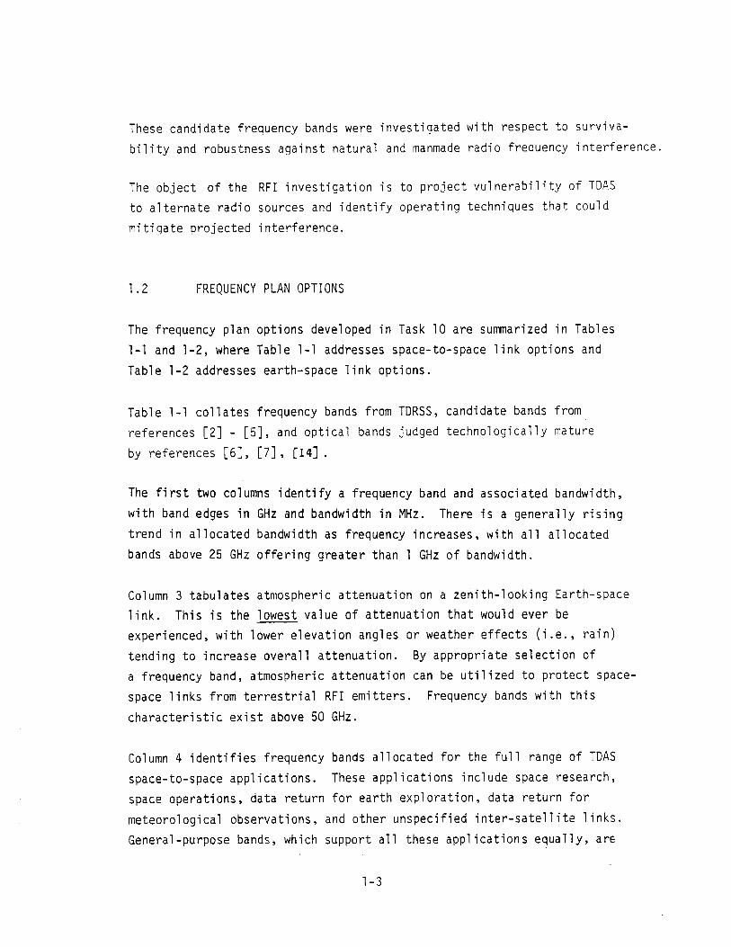
Table 1-1 collates frequency bands from TDRSS, candidate bands from
references [2] - [5] , and optical bands judged technologically mature
by references [6] , [7] , 1141 .
The f i r s t two columns identify a frequency band and associated bandwidth,
with band edges in GHz and bandwidth in MHz. There i s a generally rising trend in allocated bandwidth as frequency increases, with a l l allocated
bands above 25 GHz offering greater than 1 GHz of bandwidth.
Column 3 tabulates atmospheric attenuation on a zenith-looking Earth-space
link. This i s the lowest value of attenuation t h a t would ever be
experienced, with lower elevation angles or weather effects ( i .e . , rain)
tending to increase overall attenuation. By appropriate selection of
a frequency band, atmospheric attenuation can be uti l ized t o protect space-
space links from te r res t r i a l RFI emitters. Frequency bands with th i s
characterist ic exis t above 50 GHz.
Column 4 identif ies frequency bands allocated for the ful l range of TDAS
space-to-space applications. These applications include space research,
space operations, data return for earth exploration, data return for
meteorological observations, and other unspecified inter-sate1 1 i t e 1 inks.
General -purpose bands, which support a1 1 these appl ications equal 1 y , arE
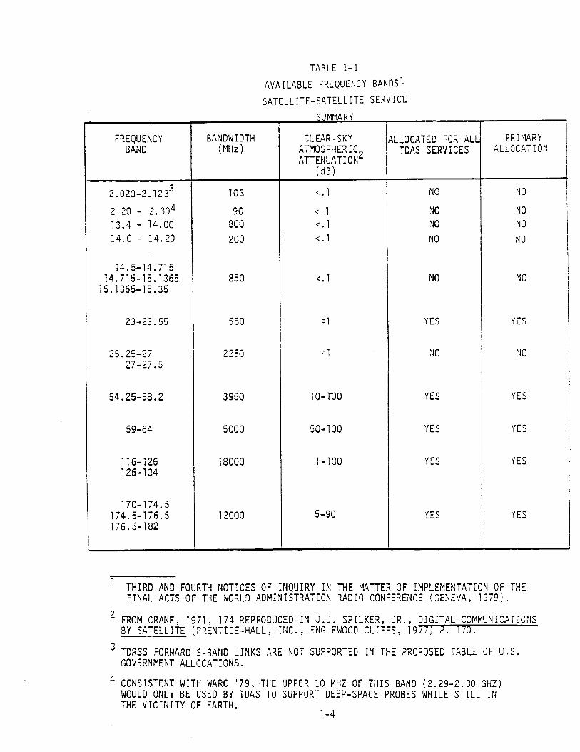
TABLE 1-1
AVAILABLE FREQUENCY BANDS^ SATELLITE-SATELLITE SERVICE
THIRD AND FOURTH NOTICES OF INQUIRY IN THE PATTER OF IMPLEMENTATION OF THE FINAL ACTS OF THE WORLD ADMINISTRATION RADIO CONFERENCE (GENEVA, 1979).
FROM CRANE, 1971, 174 REPRODUCED IN J.J. SPILKER, JR., DIGITAL COMMUNICATIONS BY SATELLITE (PRENTICE-HALL, INC. , ENGLEWOOD CLIFFS, 1977) P . 1 70.
TDRSS FORWARD S-BAND LINKS ARE NOT SUPPORTED IN THE PROPOSED TABLE OF U.S. GOVERNMENT ALLOCATIONS.
CONSISTENT WITH MARC '79, THE UPPER 10 MHZ OF THIS BAND (2.29-2.30 GHZ) WOULD ONLY BE USED BY TDAS TO SUPPORT DEEP-SPACE PROBES WHILE STILL IN THE VICINITY OF EARTH.
1-4

T A B L E 1-1
A V A I L A B L E FREQUENCY BANDS
S A T E L L I T E - S A T E L L I T E S E R V I C E
SUMMARY (CONT)
O P T I C A L BANDS ARE NOT ADDRESSED I N CURRENT OR PROPOSED REGULATIONS
FREQUENCY BAND ( GHz)
1 8 5 - 1 9 0
O P T I C A L -532 nm -832 nm - 1 0 6 0 nm
LEE , SCHROEDER, AND CLANG, R E F [9]
BANDWIDTH (MHz )
5 0 0 0
> 1 0 0 0 0
PRIMARY A L L O C A T I O N
YES
( N O T E 5 )
CLEAR-SKY ATMOSPHERIC ATTENUATION^
( d B )
( T B D )
< 5 (NOTE 6 )
ALLOCATED FOR A L L TDAS SERVICES
YES
(NOTE 5 )

TABLE 1-2
AVAI LABLF FREQUENCY BANDS^ EARTH-SATELLITE SERVICE
SUMMARY
SECOND, THIRD AND FOURTH NOTICES OF INQUIRY IN THE MATTER OF IMPLEMENTATION OF THE FINAL ACTS OF THW WORLD ADMINISTRATION RADIO CONFERENCE I GENE:!A, 1579)
CURRENTLY LIMITED TO MILITARY APPLICATIONS BY FOOTNOTE GYY4 TO THE U.S. GOVERNMENT TABLE OF FREQUENCY ALLOCATIONS.
TDAS ALLOCATION
PRIMARY
PRIMARY EXCEPT
0.402-0.403
SECONDARY
PRIMARY
SECONDARY
PRIMARY
PRIMARY
PRIMARY
SECONDARY
SECONDARY
PRIMARY
FREQUENCY BAND (GHz)
0.137-0.138
0.4001 5-0.401 0.401-0.402 0.402-0.403
0.460-0.470
1.427-1 .429
BANDWIDTH (MHz)
1
2.85
10
2
AERONAUTICAL- MOBILE
ALLOCATION
NONE
NONE
NONE
PRIMARY
1.99-2.11
2.2-2.9
7.19-7.235
8.025-8.175 8.175-8.215 8.215-8.4
8.45-8.5
13.25-13.4 13.4-14.0 14.0-14.2
14.5-14.7145 14.7145-15.1365 15.1365-15.35
20.2-21.2
TDAS SERVICES ALLOCATED
DOWNLINK
UPLINK +
DOWNLINK
DOWNLINK
UPLINK
UPLINK
DOWNLINK
SOME UPLINK
DOWNLINK
SOME UPLINK +
ALL DOWNLINK
SOME UPLINK SOME DOWNLINK
DOWNLINK
2 NONE
9 PRIMARY
45 NONE
475 SECONDARY
950 PRIMARY
I PRIMARY 8 50
1000 NONE

TABLE 1-2
A V A I L A B L E FREQUENCY BANDS
EARTH-SATELLITE SERVICE
SUMMARY (CONT)
L
GOVERNMENT TABLE OF FREQUENCY ALLOCATIONS
TDAS ALLOCATION
PRIMARY
PRIMARY~
PRIMARY
PRIMARY
PRIMARY
PRIMARY
PRIMARY
PRIMARY
PRIMARY
PRIMARY
PRIMARY,
PRIMARY
PRIMARY
U.S.
TDAS SERVICES ALLOCATED
U P L I N K
DONWLINK
U P L I N K
U P L I N K
SOME U P L I N K SOME DOWNLINK
U P L I N K
DOWNLINK
U P L I N K
DOWNLINK
DOWNLINK
U P L I N K
DOWNLINK
U P L I N K
FOOTNOTE GYY4 TO THE
AEflONAUTICAL- MOBILE
ALLOCATION
NONE
NONE
NONE
PRIMARY
SECONDARY
PRf MARY
PRIMARY
PRIMARY
PRIMARY
PRIMARY
PRIMARY
PRIMARY
PRIMARY
APPLICATIONS BY
FREQUENCY BAND ( GHz )
3 0 . 0 - 3 1 . 0
3 9 . 5 - 4 0 . 5
42 .5 -43 .5
4 7 . 2 - 5 0 . 2
6 5 - 6 6
7 1 - 7 4 7 4 - 7 5 . 5
81 -84
9 2 - 9 5
1 0 2 - 1 0 5
1 4 9 - 1 5 0 1 5 0 - 1 5 1 1 5 1 - 1 6 4
2 0 2 - 2 1 7
2 3 1 - 2 3 5 2 3 5 - 2 3 8 2 3 8 - 2 4 1
2 6 5 - 2 7 5
CURRENTLY
BANDWIDTH (MHz )
1 0 0 0
1 0 0 0
1 0 0 0
3 0 0 0
1 0 0 0
4 5 0 0
3 0 0 0
3 0 0 0
3 0 0 0
5 0 0 0
1 5 0 0 0
1 0 0 0 0
1 OPOO
L I k I T E D TO M I L I T A R Y

tabulated with a "YES". Other bands, for which service is generally restrict- ed to one of the application types noted above, are tabulated with a "NO".
For example, TDRSS K-band services are located in bands allocated on a
secondary basis to space research. NASA depends on frequency management
and coordination, with external agencies and entities, to maintain these bands without interference. The management risk for TDAS can be reduced if
new services (i.e., those not constrained to be compatible with TDRSS) are
located in general-purpose bands such as "Intersatellite" (for space-to-
space connectivity) and "Fixed-Sate1 1 ite" (for space-to-earth connectivity) .
Column 5 describes the priority of the relevant inter-satellite allocations
relative to other services that share the band. Allocations are either
primary or secondary, with primary services given preference in the event of conflict. For example, with TDAS operating as a primary service, and with RFI from a secondary service, the secondary service would be required
to modify its operations and cease interference. A1 ternatively, TDAS would
be required to modify operations if the positions were reversed.* The
security value of a primary allocation is clear.
Optical wavelengths are candidates for TDAS inter-satellite service. These
wave1 engths are currently outside the scope of national and international
allocations, and therefore available for any application. The draft fre-
quency plan identifies optical wavelengths as suitable for space-space
applications only--weather affects make optical wavelengths unsuitable for fixed-satell ite service in an operational system such as TOAS.** Current
optical techno1 ogies that show promi se for near-term space-qua1 if ication
are in the infrared and blue-green regions of the spectrum [6], [14]
* The order of assignment is unimportant in cases of interference across allocation levels. But with interference among services at the same a1 location 1 eve1 , the 01 dest service has preference.
** Cloud-induced losses > 5 dB can be expected approximately 85% of the time [9], page 95.

Viewed as a whole, Table 1-1 indicates that allocated bands above 50 GHz
are desirable in many respects from a frequency management perspective.
These bands offer primary a1 locations for a1 1 TDAS space-to-s~ace 1 inks,
with bandwidths in excess of 1 GHz and atmospheric protection against
t e r res t r i a l RFI emitters. Selected bands below 50 GHz may be suitable
for speci a1 appl ica t i ons.
Table 1-2 coll ates earth-sate1 1 i t e bands from TDRSS and proposed regulations.
Columns 1 and 2 are similar to Table 1 -1 , describing frequency band and
bandwidth for each s e t of adjacent allocated bands. For example, three
adjacent bands from 0.40015 GHz to 0.403 GHz have a combined bandwidth
of 2.85 MHz. Whereas the lowest frequency fo r space-to-space appl ications
was 2.02 GHz, earth-space allocations extend down to 137 MHz. The
relat ively narrow bandwidths a t lower frequencies make these bands
unsuitable fo r trunking or high data rate downlinks; b u t they may be
used for special purpose and command links.
Column 3 identif ies the a1 location level of the aeronautical-mobile service.
This service presents a threat to the TDAS-ground downlink, since an airborne
platform could in ject high-level RFI direct ly into the mainbeam of the
ground receive antenna. Legal precedence over the aeronautical service
i s highly desirable, t o protect against th i s form of unintentional in ter-
ference. Column 3 may be compared t o column 5 to determine the precedence
relationship. Bands not allocated to the aeronautical-mobile service ( " N O N E "
in column 3 ) are most preferred in th i s regard. (See Section 3 for a more
complete discussion of th i s problem).
Columns 4 and 5 identify TDAS services that can be supported and t he i r level
of allocation. For example, the band 137-138 MHz i s allocated t o a l l down-
link services on a primary basis. The terms "SOME UPLINK" and "SOME DOWN-
LINKS" identify specif ic allocations in the related band. The 7.19-7.235 GHz
band, for example, i s limited to uplink applications in the space research
service. This band would be nominally off-limits for space operations,
earth-exploration, e tc . The exact lfmitations are identified in Section 2 ,
Table 2-4.

In the 20-40 GHz range, government use of a l l bands allocated t o services
applicable t o TDAS i s limited to military applications by footnote GYY4
(U .S . Table of Frequency A 1 locations). However, cooperation among government
users of the spectrum i s possible, and probably desirable. This i s particularly
true for TDAS, where the military and a l l other users would benefit through
shared use of optimal resources.* This issue highlights the need for ongoing
frequency management a t the policy level. Current decisions being made by
frequency management policy makers will determine the avai labi l i ty of the
30/20 G H z band to TDAS applications.
1.3 SURVIVABILITY A N D ROBUSTNESS AGAINST RFI
In the context of th i s report, the term Radio Frequency Interference
(RFI) i s restr icted to unintentional interference t o TDAS communication
1 inks by electromagnetic radiation. This includes natural and manmade
sources. In th is context, the terms "survivability" and "robustness"
should be viewed in the following quali tat ive sense: A survivable system
i s able . t o operate in any anticipated RFI environment. A robust system,
on the other hand, provides some level of resistance and graceful degradation
in the presence of harsh RFI environments without guaranteeing a specific
level of performance.
For the purpose of long rang planning four classes of radio frequency
interference (RFI) can be identif ied:
1. Natural sources. The sum emi t s electromagnetic radiation
a t a l l frequencies of interest to TDAS, and therefore represents
an important source of RFI for selected geometries.
* For a given weight and power limitation, shared channel resources should result in greater capacity and avai labi l i ty for a l l users, relat ive t o a system with physically duplicated components a t different frequency bands.

2. Sel f-interference. In system configurations where several
user s a t e l l i t e s (USATs) share a common operating frequency,
self-interference could lead t o unacceptable degradation of
user signaling.
3 . Other civi l ian services. Many frequency bands that are physically
appropriate for TDAS are allocated jointly t o several radio
services. In cases where a non-TDAS service i s granted higher
allocation status relat ive t o TDAS, degradation of TDAS signaling
could take place without regulatory remedy.
4. Military services. Certain strategic and tact ical radars
represent high-power sources of unintentional RFI. These
sources currently represent a degradation with respect t o
TDRSS frequency bands which can be expected to become more
severe in the future.
TDAS survivability t o these RFI sources i s a function of projected system
architecture, spacecraft design, user mission profiles and time of year
(part icularly with respect t o solar outages). A t the current study
level , a preliminary discussion of survivabil i ty i s therefore 1 imi ted
t o potential RFI scenarios. Man-made RFI emitters are assumed t o fu l ly
uti 1 ize the RF spectrum consistent with proposed FCC/NTIA regulations
(based on WARC '79 and the FCC Notices of Inquiry in response t o the
WARC) .
TDAS survivability and robustness can be improved by incorporation of
elements from the following l i s t :
1. A 1 ternate routing capabi 1 i ty to bypass 1 inks with temporary
RFI;
2. Frequency band selection t o take advantage of atmospheric
attenuation;

3. Coding/interleaving optimized for RFI;
4. Improved hardware to provide higher transmitt EIRP or receive
G/T, and the use of adaptive techniques such as antenna pattern
nu1 1 ing;
5. Command verification protocols to trap undetected errors in
forward 1 ink commands.
These techniques are related to particular sources of RFI.in the discussion
below, and addressed in greater detail in Section 4 of this report.
Solar RFI causes a "sun transit outage" which occurs when pointing
angles from a receiving antenna to a transmitting satellite and the
sun are so near coincidence that both are within the receiving antenna
beamwidth. The receiving antenna can be at an earth station or on a
satellite. Solar RFI is paricularly troublesome on and around the spring
and autumn equinoxes, when satellites in .near-equatorial orbits have
high probability of achieving colinearity with the sun. In addition,
spacecraft in nonequatorial orbits have windows of vulnerability which
become larger in time as orbital inclination increases.
During any solar/satellite conjunction*, reliable communication is impossible
during actual colinearity. But at the cost of the increased spacecraft
power/wei ght , the effects of con junction can be mi ti gated be improved transmit EIRP, receive G/T, or usage of lower-rate FEC coding. An alternative
approach is maintenance of a dual-routing or mu1 tiple-routing capability.
Since solar conjunctions are easily predicted for a1 1 spacecraft and.
spacecraft-earth terminal pairs, alternative routing through the multi-
satellite TDAS network can yield signficant gains in channel availability.
The cost here is in ground software complexity, where additional constraints
would be imposed on the TDAS scheduling algorithms.
* A receiving station views a transmitting spacecraft as well as the sun in the high-gain portion of its antenna beam.

RFI caused by sel f-interference can become a problem i n system configurations
that rely on beam discrimination t o separate transmissions from various
user spacecraft. RFI may exis t when a TOAS s a t e l l i t e attempts t o service
two user spacecraft with small angular separation (as viewed from TDAS).
Appropriate schedul i n g techniques can mi t igate th is problem, by grouping
user spacecraft i n se ts such that members of a set are angularly separate
from one another a t the time of service. TDAS then services one set
a t a time, without self-interference. An important element of such
scheduling i s the al ternative routing capability discussed above. Simulation
would be desirable to determine the improvement available with these
techniques for a particular TDAS configuration and user constel la t ion.
Other mitigating techniques include improved receiver antenna gain,
improved modulation techniques that res is t interference ( i . e . , coding),
or techniques that provide diversity against i t ( i . e . , FDMA, TDMA, CDMA,
polarization diversi ty, etc. ) .
Lawful interference from other civi l ian services i s due t o the shared
allocation strategy pursued by FCC/NTIA. All frequency bands of in teres t
are jointly a1 located to several user classes. For example, frequency
bands allocated to space-earth downlink operations may be simultaneously allocated to fixed and mobile t e r res t r i a l user services.
Operating frequencies should be chosen t o minimize the chance of conf l ic t
as well as maximize the TDAS precedence level should conf l ic ts occur -- t h u s insuring that TDAS services are protected w i t h the force of regulation.
The ideal s i tuat ion i s a primary allocation for TDAS-type service, with a l l
other services allocated on a secondary basis only. Less desirable s i tua-
tions are shared allocations on a primary basis to TDAS as well as other
services , or secondary a1 1 ocati on s t a tus to TDAS - type services. Regulatory
precedence fo r TDAS i s most desirable on space-to-space link al locations,
where variable geometries among TDAS and user spacecraft permit interference
from vir tual ly a1 1 t e r r e s t r i a l locations. Space-space 1 inks can be protected
by judicious selection of frequency bands i n the atmospheric absorption regions
around 60 GHz. Attenuation of t e r r e s t r i a l emissions in excess of 50 dB

can be achieved by careful band selection, making the question o f t e r res t r i a l
RFI vir tually moot. Up/down link allocations cannot take advantage of
atmospheric attenuation, b u t ground equipment design can mi t igate most pro-
blems o f manmade RFI. A combination of high-power, h i g h gain u p l i n k trans-
mission can protect the uplink, while the h i g h gain receiver possibly coupled
w i t h sidelobe suppression equipment can protect the downlink. The major threat
with respect t o downlink RFI becomes the mobile aeronautical service, which
could in ject RFI from an airborne transmitter directly i n t o the main beam of
the TDAS ground receiver. A primary allocation status for TDAS i s the most
straightforward mi t i gation technique in th is case, b u t certain modulation
techniques may prove effective w i t h further research. In part icular , coding
and interleaving may prove effective depending on projected a i rc ra f t dynamics
and the radio operation regime of airborne users.
Military services of the United States and foreign countries employ radar transmitters that pose an unintentional hazard to TDAS. Main beam-to-main
beam coupl i n g from s t ra tegic radars can exis t regardless of emitter location
on the ea r th ' s surface. Tactical radars, with the i r relat ively low-elevation
scanning angles, are chiefly a problem near the ea r th ' s limb (as viewed by the receiving spacecraft) . Space-to-space 1 inks are particularly vulnerable
to radar emissions, due to the re1 at ive spacecraft motions that bring different
parts of the earth i n t o view of the receiving spacecraft. Characterization of th i s hazard i s d i f f i cu l t , particularly with respect to current and future
planning of foreign nations. In view of these d i f f i cu l t i e s , a n d the
documented impact on TDRSS [ I l l , i t i s prudent to incorporate techniques
to guarantee TDAS robustness. These techniques include:
1 . A1 ternative routing capabil i ty.
2. Band selection t o optimize atmospheric screening. 3. High-gain receive antennas t o minimize coupl i ng.
4. Coding/interleaving optimized for projected RFI.

Since most ground terminals are a t inland locations within CONUS, and most
U.S. radars are located near the coasts,* up /down links are less vulnerable t o
radar interference than space-to-space links. Coastal and near-coastal
s i t e s may experience vulnerability t o U.S. tact ical radar emissions as a
function of frequency band, ground s i t e equipment, TDAS orbital location,
t e r res t r i a l geography in the vicinity of the ground s i t e , a n d radar operating
regime.
With respect to the general RFI problem described above, command verification
protocols can provide significant operational robustness even with degrada-
tion of data. Comand verification involves echo-back of commands t o the
originating authority, where the echo i s compared to a copy of the original
command. If the echo matches the copy, a go-ahead signal i s transmitted.
This signal triggers execution of the command, which was read b u t not immediat-
ly implemented by the receiving sate1 1 i t e . Command cycle time i s approximately
tr ipled due to three transmissions instead of one ( i n i t i a l command, echo-
back and go-ahead) .** Command verification a1 so i nvol ves an increase i n
spacecraft command processor complexity -- t o handle echo-backs, latching of
commands, verification timeout periods, e tc . With these costs , however, the
probabil i ty of uncommanded spacecraft action i s vir tually el iminated.
1.4 ORGANIZATION OF REPORT
This report i s organized in 4 sections as follows:
Section
1
CONTENTS
Introduction. Discusses method01 ogy , major
conclusions i n the form of frequency plan options,
and a description of report organization.
Candidate Bands for TDAS Service. Discusses
a1 1 bands authorized for TDAS inter-sate1 1 i t e
and f ixed-sate l l i te service.
* Foreign radars are naturally excluded from CONUS.
** Processor delays are assumed negligible relat ive t o the propagation delays.

Projected Surv ivab i l i ty to RFI. Projects
impact of RFI on various bands i den t i f i ed
in Section 2 , via a geometric in te r fe rence
model and a1 t e rna t e se rv ices authorized i n
the In te rna t iona l and U.S. Tables of
Frequency A1 l oca t i ons .
Techniques f o r Robust Operation. Discusses
modulation, a r ch i t e c tu r a l and operat i onal
techniques capable o f mi t i gat ing RFI.

SECTION 2
CANDIDATE BANDS FOR TDAS SERVICE
This section ident i f ies candidate frequency bands for TDAS use. These bands
are suggested by three sources:
1. Current TDRSS frequency ut i l iza t ion plan.
2. Proposed regulations of the NTIA/FCC, consistent with the f inal
acts of the NARC (Geneva, 1979).
3 . Techno1 ogy projections fo r 1 aser-based communication systems.
The in tent a t t h i s stage i s to identify a broad s e t of frequency bands
sui table fo r TDAS, maintaining suff ic ient la t i tude to allow engineering
tradeoffs a t a l a t e r date. The union of a l l frequency bands suggested by
the above three sources i s developed in t h i s section -- no e f fo r t i s made
to eliminate candidate bands on the basis of engineering or economic
feas ib i l i ty . However, issues of concern are highlighted in the t ex t
wherever imp1 ementati on of a part icular frequency band would encounter known
obstacles. The contributions of the above sources are discussed in turn
be1 ow.
2.1 TDRSS FREQUENCY UTILIZATION PLAN
The TDRSS frequency bands are identif ied in Table 2-1. These bands represent
proven technology and can be made interoperable with TDAS to support
t ransi t ion service. Offsetting these advantages, TDRSS bands will be
affected by RFI from man-made t e r r e s t r i a l emitters (Section 3 ) . These
emitters ex i s t a t S-band and K-band, affecting forward and return 1 ink
service between TDRSS and user s a t e l l i t e s . The problem i s currently
most severe a t S-band, where signigicant depl oyrnents of a i r defense radars
share the TDRSS bands. Main-beam-to-main-beam coup1 ing wi 11 occur with
re la t ive ly high probability.

TABLE 2 - 1
TBRSS FRE2UENCY BANDS
S e r v i c e Frequency 1 (MHz)
Forward Links
MA 2103 - 2110
SSA 2020 - 2123
KSA 13748 - 13802
j Return Links
i MA 2284 - 2290 SSA 2200 - 2300
KSA 14888 - 15119
Composite Down1 ink 2 13401 - 14044
Composi t e Up1 ink 2 14599 - 15226
1 Frequency band edges a r e g iven t o t h e n e a r e s t MHz, a s sensed
by t h e r e c i p i e n t .
2 Composite bandwidths f o r up l ink and downlink a r e no t f u l l y
occupied .

K-band i n t e r f e r e n c e w i l l be l e s s severe because o f 1 i m i t e d deployment
o f K-band equipment, t he i n t e r m i t t e n t o p e r a t i n g regime o f may o f these
rada r se ts , and the a p p l i c a t i o n o f these radars t o p r i m a r i l y t a c t i c a l
miss ions . The r e l a t i v e l y low main-beam e l e v a t i o n angle o f these t a c t i c a l
radars i m p l i e s low p r o b a b i l i t y o f main-beam-to-main-beam coup l i ng except
when TDRSS i 11 umi nates t e r r i t o r y near the e a r t h ' s 1 imb.
Many of TDRSS's a n t i c i p a t e d problems w i t h RFI stem from a l a c k o f knowledge
of these RFI sources when t h e TDRSS des ign was f i n a l i z e d . Th i s y i e l d e d a
system c o n f i g u r a t i o n t h a t i s suboptimum f o r t h e a c t u a l envi ronment. With
proper eng inee r ing design, much o f t h i s impact cou ld be avoided i n a f o l l o w -
on TDAS. On t h e o t h e r hand, t he deployment l e v e l , s i g n a l s t r e n g t h and oper-
a t i n g regimes o f m i l i t a r y radars a re l i k e l y t o i nc rease i n t h e coming decade.
Any TDAS des ign based on these f requencies f o r TDAS-USAT l i n k suppor t must
cons ide r t h i s i ssue c a r e f u l l y .
The u p l i n k / d o w n l i n k TDRSS band i s c u r r e n t l y una f fec ted by K-band rada r RFI
s i n c e these l i n k s te rm ina te w e l l w i t h i n t h e i n t e r i o r o f CONUS. Th i s o f f e r s
p r o t e c t i o n a g a i n s t U. S. t a c t i c a l K-band radars , which a r e t y p i c a l l y deployed
o u t s i d e o f CONUS. With respec t t o TDAS, system c o n f i g u r a t i o n s w i t h a l t e r -
n a t i v e ground s i t e s near U.S. shore1 i n e may exper ience some deg rada t i on on
K-band up1 i n k s and down1 i n k s as w e l l .
2.2 PROPOSED ALLOCATIONS DUE TO WARC ' 7 9
The FCC has pub l i shed f o u r No t i ces o f I n q u i r y (NOI ' s ) i n t he m a t t e r o f
imp1 ementat i on o f t he f i n a l a c t s o f t he World A d m i n i s t r a t i v e Radio Conference
h e l d i n Geneva i n 1979 [Z] - [5]. These No t i ces o f I n q u i r y * coo rd ina te
t h e p o s i t i o n s o f t he FCC and the NTIA. The FCC** r e g u l a t e s the U.S.
nongovernrnent te lecommunicat ions community. The NTIA*** coo rd ina tes
* Hencefor th, t h e term "No t i ce (s ) o f I n q u i r y " should be const rued as r e f e r r i n g t o one ( o r severa l ) o f re ferences [ 2 ] - [5].
** FCC = Federal Communications Communication
*** NTIA = Na t i ona l Telecommunication and I n f o r m a t i o n A d m i n i s t r a t i o n .

the U.S. government telecommunications community ( t h i s includes uses
of the radio spectrum for purposes other than communication, such as
radiolocation ( r ada r ) ) . These documents have been ra t i f ied by the Senate
and are awaiting Presidential signature. They represent the current
best estimate of the U.S. regulatory framework for the 1980's and beyond.
The NO1 format i s i l lus t ra ted in Figure 2-1, which i s a n excerpt from the
third NOI. The frequency spectrum i s divided into dis jo int b u t contiguous
intervals according t o allocated service. For example, the band 20.2 - 2 1 . 2 GHz i s allocated t o s a t e l l i t e downlink service for fixed or mobile
earth stat ions in government systems. The use of a l l capitals (i . e . ,
"FIXED-SATELLITE") indicates primary allocation s ta tus ; the use of lead-
ing capital s ( i . e . , "Standard Frequency and Time Signal -Satel 1 i t e " )
indicates secondary a1 location s ta tus . In confl i c t s among services a t d i f ferent allocation levels , the secondary service must give way t o the
primary service. Primary services may continue t o interfere with second-
ary services, b u t n o t vice versa. Where they ex i s t , parenthetical expres-
sions represent limitations on a particular service. For example, a l l
services in Figure 2-1 are limited to space-to-earth links. Other bands
would be needed to support earth-to-space uplinks or space-to-space cross-
1 inks. Footnotes add additional 1 imitations and refinements t o the a1 lo-
cation table. In Figure 2-1, the U.S. Government footnote G Y Y 4 1 imits the
i 11 ustrated band t o mi 1 i tary operati ons.
Since TDAS i s envisioned primarily as a service of the U.S. qovernment,
the Table of Government Allocations was examined for applicable service
authorizations. Non-government use i s not precluded by th i s approach since
coordination t h r o u g h NASA would be a1 1 owed. A1 1 ocations appl icabl e t o TDAS
service are l i s ted in Table 2-2, where a dichotomy i s introduced t o identify
service classif icat ions by link type or end-use. In te r - sa te l l i t e service
applies to any sa te l l i t e - to - sa te l l i t e service, regardless of data type a n d
spacecraft identi ty. Fixed-sate1 1 i t e service simi 1 a r ly appl i es t o any u p /
downlink between a s a t e l l i t e and ground s ta t ion. Services classif ied by
end use are nominally limited to particular user classes. I n the absence
FIGURE 2-1 : SAMPLE FORMAT E F C C NOTICE OF INQUIRY
(PROPOSED) .------------------+------------------+------------------
INTERNATIONAL TABLE .................... ------------------
A1 locat Gllz ion 1 1 A!:::i:n
(1) l - - I - - - -P-=D-=- - l - - - ----I-------------- -.---------.--I----=
FIXED SATELLITE (space-to-Earth) Hobile-Satellite (space-to-Earth)
FIXED-SATELLITE (space-to-Earth) MOBILE-SATELLITE (epace-to-Earth) Standard Frequency and Time Signal
Satellite (epace-to-Earth)
CYY4 In the bands 7250-7750 and 7900-8400 HIIz and 20.2-21.2, 30-31, 39.5-40.5, 43.5-45.5 and
50.4-51.4 CHz the fixed-eatellite and mobile-eatsllite aervices are limited to military operations-

TABLE 2-2 SERVICE CLASS1 F I CAT1 ONS APPLICABLE TO TDAS
Services Classified by Link Type Services Classified by End-Use*
Intersatel 1 i t e Space Operations *
Fi xed-Sate1 1 i t e Space Research
Meteor01 o g i cal -Satel 1 i t e
Earth Exploration-Sate11 i t e
* Limitations may apply, indicated in the Table of Frequency
Allocations by a parenthetical expression. For example,
Meteorological -Satel 1 i t e (space-to-earth) would 1 imi t the indicated band t o downlinks from meteorological s a t e l l i t e s .

of specif ic coordinating agreements by a1 1 interested par t ies , for example,
the space telescope would be precluded from a band allocated solely to the meteorological-sate1 1 i t e service. Such end use c lass i f ica t ions are d i f f i -
cu l t to incorporate i n a TDAS intended for broad user support. Bands
allocated in th i s way a re , nevertheless, retained a t th i s stage t o provide
maximum f l e x i b i l i t y for future tradeoffs.
The strategy employed was to examine a l l frequency bands in the proposed
U.S. Table of Government Allocations and extract those bands applicable
to TDAS. Table 2-3 1 i s t s a l l bands applicable t o the inter-sate1 1 i t e
service, including bands c lass i f ied by enduse tha t support space-to-space service. Table 2-4 l i s t s a l l bands applicable to the f ixed-sa te l l i t e
service (up1 inks and down1 inks to fixed earth s ta t ions) , including bands
c lass i f ied by enduse that support up1 ink/downl ink service. For
each band of in te res t , the a l locat ion(s) i n support of TDAS-type ac t iv i ty
i s indicated in column 2 -- "A1 located Services Relevant to TDAS."
Other service a1 1 ocations for government a n d non-government users are l i s t e d in column 3 . This allows comparison of TDAS allocation s ta tus
t o the allocation s ta tus of a l l other services. Comments are added
where required t o describe related data and footnotes tha t may modify the sense of allocation.
Tables 2-3 and 2-4 indicate extensive support i n the proposed regulatory
framework for TDAS and TDAS-like service. However, certain discrepancies may be noted among TDRSS frequency bands, ongoing research in space comrnunica- tions and the pooposed regulations.
With respect to TDRSS frequency bands, comparison of Table 2-1 and Tables 2-3 and 2-4 indicate l i t t l e support for TDRSS in the proposed al locat ions.
Forward links (TDRSS-to-User) a t S-band are not authorized in any way.
All other services are abthorized on a secondary basis and only for "space
research". TDRSS services are only protected from interference by ongoing
participation of NASA frequency managers.

TABLE 2-3
INTER-SATELLITE BANDS

TABLE 2-3
INTER-SATELLITE BANDS (CONT)
* See Glossary f o r D e f i n i t i o n o f these terms
Bands (GHz)
14.0 - 14.2
14.5 - 14.7145
14.7145 - 15.1365
15.1365 - 15.35
23 - 23.55
25.25 - 27
A1 1 oca t e d Services r e 1 evant t o TDAS
Space Research
Space Research
Space Research
Space Research
INTER-SATELLITE
Ear th Exp lo ra t i on - Sa t e l l i t e
(space-to-space)
Other A1 1 oca t e d Serv ices
FIXED-SATELLITE (Earth- to-space)
RADIONAV IGAT ION
FIXED Mobi 1 e
MOBILE F ixed
FIXED Mobi 1 e
FIXED MOBILE
FIXED MOBILE
Standard Frequency and t i n ~ e S a t e l l i t e
( ~ a r t h - t o - s p a c e )
- -.
Comments
Not a l l da ta se rv i ces au tho r i zed
Secondary a1 l o c a t i o n o n l y
Not a l l da ta se rv i ces au tho r i zed
Secondary a1 1 o c a t i o n o n l y
Not a l l data se rv i ces au tho r i zed
Secondary a1 1 o c a t i o n o n l y
Not a l l da ta se rv i ces au tho r i zed
Secondary a1 1 o c a t i o n o n l y
Passive sensing i n t h i s band
Radio astronomy i n upper ad jacen t band
Radio astronomy s p e c t r a l l i n e observat ions a t 23.07 - 23.12 GHz ( f o o t n o t e 3801 D)
- . - - -

TABLE 2-3
INTER-SATELLITE BANDS (CONT)
Band (GHz) O the r A1 l o c a t e d S e r v i c e s
-.
FIXED MOBILE
A1 l o c a t e d S e r v i c e s r e l e v e n t t o TDAS
E a r t h E x p l o r a t i o n - S a t e l l i t e
(space- to -space)
INTER-SATELLITE
INTER-SATELL ITE
INTER-SATELL ITE
INTER-SATELLITE
INTER-SATELLITE
- - --
EARTH EXPLORATION- SATELLITE ( p a s s i v e )
FIXED MOBILE SPACE RESEARCH
( p a s s i v e )
FIXED MOBILE RADIOLOCAT ION
EARTH EXPLORATION- SATELLITE ( p a s s i v e )
FIXED MOBILE SPACE RESEARCH
( p a s s i v e )
FIXED MOBILE RADIOLOCATION
Comments
* EES and I S s e r v i c e s n o t p r o t e c t e d a g a i n s t FIXED and MOBILE s e r v i c e s
Federa l Republ i c o f Ger~nany , Japan, and UK a1 l o c a t e t h i s band t o r a d i o l o c a t i o n on a p r i m a r y b a s i s
Oxygen a b s o r p t i o n band
I n d u s t r i a l , s c i e n t i f i c and med ica l s e r v i c e i n 61 - 61.5 GHz, w i t h s p e c i a l adirri n i s t r a - t i o n a u t h o r i z a t i o n
* ISM o p e r a t i o n s may be a u t h o r i z e d i n 122 - 123 GHz
Rad io astrononry i n l owe r ad ja - c e n t band
FIXED MOBILE
174.42 - 175 .02 GHz a l l o c a t e d t o Radio astronoirry or1 a second-
. -

m C, C
0 U
u aJ C, a U m
2 -.r 4 : >
L L a w c CI 0
m aJ v, U Q .r a L >I- a 0 mc,
C , aJ c C a J a > U a J O F
7 a J 7 L -=z
h
N X a V
u s a m
u w
I m C, 0 .r O I U L a L L Ul C, C a, 5 a, 4 a h a CL 0 V) a V) h Q 7 S a C 7 U3 3 - 0 -
N h 0 . a I O L .r S aJ S a.7 a 42 .r h 'r N 2 5 u u a - N r 0
CU 5 s ocr 0
U - 0 m o w -CCUUI 8 s . ~ , a s s hQU l a 0 .d O a WUlR or0 - L n
-a a huh- c-, I aJ Lmf-CO m C , C, 8 a a E I . r r r J 5 S
N a 0 U aJ -0 -0 aJ b U S o d l O U CUaC O U 0 2 , 0'- . era . C Z O .rf8
- 4 - 7 E v w h l - u-3 a u -0.3 hl- 0 aJ a h a COOU - a s mar7 - = a - * m c ra
h
aJ >
I 'r Z m
E: n W
O W I-
kt; X - 1
s 0
W - 1 -1 W W W .d XI-Qd C3- I
W u 4:
I - 4 W c r m x m x m I- - 0 u o 0 5 L L E L L r Z
W W W
L 0 = 5 t, Q 1 cr J -.I W J < -I --I + W W W W I- v, I- I-
4 3
2 0 2 z v, 1 I 1
QC W CZ CZ 4 W U W W I- I- I- + Z 2 Z Z
u 0
u v, u Z
m
a CU h CO 7 7 0 0
o', I I 7
0 d
m m I I
d '9 U Y 0 h h aJ 0 - - 7 m


TABLE 2-4
FIXED-SATELLITE BANDS (CONT)
Other A1 1 oca t e d Serv ices
Band (GHz)
0.460 - 0.470
Comments
LAND MOBILE I U.S. FOOTNOTE 201: I
A1 1 oca t e d Serv ices Re1 event t o TDAS
M e t e o r o l o g i c a l - S a t e l l i t e ( space-to-earth) I n t h e band 460 - 470 MHz,
space s t a t i o n s i n t h e e a r t h e x p l o r a t i o n sate1 1 i t e se r - v i c e may be au tho r i zed f o r space- to -ear th t r a n s n ~ i s s i o n s on a secondary bas i s w i t h r e s p e c t t o t h e f i x e d and mo- b i 1 e se rv i ces . When opera- t i n g i n t h e me teo ro log i ca l - sate1 1 i t e se rv i ce , such s t a t i o n s s h a l l be p r o t e c t e d f rom harmfu l i n t e r f e r e n c e f rom o t h e r a p p l i c a t i o n s o f t h e e a r t h exp l o r a t i o n - s a t e l - 1 i t e s e r v i c e . The power f l u x i n t h i s band s h a l l n o t exceed -1 52 dBw/m**2/4kHz.
.
As s p e c i f i e d i n U.S. Footnote 216, t h e f requency bands 460.5125 - 460.5625, 462.9875 - 463.1875, 465.5125 - 465. 5625 and 467.9875 - 468.1875 MHz a re au tho r i zed f o r Govern- mentlnon-Government ope ra t i ons i n medical r a d i o c o m ~ u n i c a t i o n s systems .

TABLE 2-4
FIXED-SATELLITE BANDS (GONT)
FIXED MOBILE
Band ( GHz)
1 .427 - 1.429
1 .990 - 2.110
2 . 2 - 2.29
O t h e r A1 l o c a t e d S e r v i c e s
FIXED MOBILE e x c e p t ae ro -
n a u t i c a l m o b i l e
F i x e d ( t e l e m e t e r i n g )
Land M o b i l e ( t e l e - m e t e r i n g and t e l e - command )
FIXED MOBILE
A1 1 oca t e d S e r v i c e s Re1 even t t o TDAS
SPACE OPERATION ( E a r t h - t o - space )
[See Comments]
SPACE RESEARCH ( space - t o -Ea r t h ) (space- to -space)
-
Comments
Rad io ast rononly i n l o w e r a d j a c e n t band
SET1 b y sonie c o u n t r i e s
Foo tno tes 1 i s t e d be low a l l o w Ea r t h - t o - space and space- to -space o p e r a t i o n s f o r space r e s e a r c h and E a r t h e x p l o r a t i o n s e r v i c e , w i t h some r e s t r i c t i o n s and on a case-by-case b a s i s .
R e l e v e n t Foo tno tes : U.S. 90 U.S. 111
C u r r e n t u t i l i z a t i o n by government e a r t h s t a t i o n s i n t h e band 2 0 3 5 - 21 10 MHz
Foo tno te GI01 a1 lows space o p e r a t i o n s (space- t o - e a r t h ) on a coequal b a s i s
TDRSS MA a t c e n t e r f r e - quency o f 2287 .5 MHz
E x t e n s i v e KFP (111i l i t a r y )

TABLE 2-4
FIXED-SATELLITE BANDS (CONT)
-
A1 1 ocated Serv ices Relevent t o TDAS
SPACE RESEARCH (Ear th- to -space)
FIXED-SATELLITE (space-to-Earth)
EARTH EXPLORATION- SATELLITE ( space-to-Earth)
FIXED-SATELL ITE (Ea r th - to-space)
EARTH EXPLORATION SATELLITE (space-to-Earth)
FIXED-SATELLITE (Earth- to-space)
METEOROLOGICAL- SATELLITE (Earth- to-space)
Band (GHz)
7.19 - 7.235
7.25 - 7.30
8.025 - 8.175
8.175 - 8.215
Other A1 l o c a t e d Serv ices
FIXED
MOB ILE-SATELLITE (space- to -Ear th)
F i xed
FIXED
Mobi 1 e - S a t e l l i t e (no a i r b o r n e t ransmiss ions )
FIXED
Mobi l e - S a t e l l i t e (Ear th - to -space) (no a i r b o r n e t ransmi ss ions )
--
t
Comments
Pass ive microwave sensing performed i n t h i s band
Government use i s l i m i t e d t o m i l i t a r y ope ra t i ons by f o o t n o t e GYY4
Non-government a1 l o c a t i o n i s p r imary f o r EES.
A u t h o r i z a t i o n s on a case- by-case b a s i s f o r EES.
F ixed-sa te1 1 i t e s e r v i c e l i m i t e d t o m i l i t a r y
Non-government a l l o c a t i o n i s p r imary f o r EES.
A u t h o r i z a t i o n s on a case- by-case bas i s f o r EES.
F ixed-sa te1 1 i t e s e r v i c e 1 i m i t e d t o nli 1 i t a r y
--

m C, s
2 7 c 0 u
-a aJ C, a v 0 m - aJ - v < -7
> L L a J a J r m C, 0
V)
aJ m U=c
a > ,- L a 0 cn C, -0 C, a~ s C, aJ a > u a 0 7 7 aJ 7 e 5
s I 0 aJ . ? m aJ C, 5 . u 5 u cn .? U W 0 . 5 w 2 % - Ul aJ L 7 W S L m a 5 W 0 0 C,
Y- aJ .r C , L m 4 2 - S O s m 'P.? a % 0-7 - E E .7 m - = % +Jg 5 3 1 L L a 5 N a > E . ? a , m u 0.7 L w l l a 0 1 1 0 5 ut' I a r o a - r 4 1 x~ o m 2 % z.? < n L-
h 3 I c r -
a a p t ' a- ~ J U - 3 a ~ u 0 W i U ul G-C 5 Z W 5 C . r C 1 a J C aJ G7W 2 + = a , ? m S O Z L . r - l + m =
I L . r ZLLm + 1 l S a J O O r n a)- 4 - 1 0 L ++a m I - V a J t ' a J 0 W C , a J a I L-r < L E . r u Y + I > m r . 7 E U 5 . r - 5 > ax 0
c , m m - o-a+F--= a m C , m a J L s 1 s a m z L c
a - m o r n o m u + I o a a o W . r W S L u + S 5 0 U W W S x n - v c , a m m m c l n xu- l+ 0 < - L L r: CT z LL
I I
n n h h Z T w x
0 - z 2 W W m C, U L a
a + = a = x a c n c -t I- W - " - ,GO U a J u m U U 2 I 1 1 L . r C T l L I L L O W 0 J o o m m 0 a a 5 5 aJC, J I -C , w C , n m aJ aJ O - u l I- I L . r V ) l m I V) V, x ~ a ~ 5r .7 E W ~ J a x Q) a ~ W J U V ) C , a m u C T o CT CT
W a I L E: a L I
X I -P a a o m W Q a 5 Q) Q) I - < m W W E L U r n V W 0 U C T c n v XWWC, 2 - mu a a i5 Y a n a
LL cn Cn m m
n N I a V
V S a m
d d 0 CV
Ln m a3 d d
a3 Y 7
I I I I I
Ln Ln 7 Ln N cf 0 N U l
m m e- a3 a3 7 7 - 1

TABLE 2-4
FIXED SATELLITE BANDS (CONT)
MOBILE F ixed
Band (GHz)
14.5 - 14.7145
14.71 45 - 15.1365
15.1365 - 15.35
20.2 - 21.2
30.0 - 31 .O
FIXED Mobi 1 e
A1 1 oca t e d Serv ices re1 event t o TDAS
Space Research
Space Research
Space Research
FIXED-SATELLITE (space-to- Ear th )
FIXED-SATELLITE (Earth- to-space)
Other A1 1 oca t e d Serv ices
FIXED Mobi 1 e
MOBILE-SATELLITE (space- to -Ear th)
Standard Frequency and Time S igna l - Sate1 1 i t e (space- t o -Ea r th )
MOBILE-SATELLITE (Ear th- to -space)
Standard Frequency and Time S igna l - Sate1 1 i t e (space- t o -Ea r th )
---- x-_
Comments
L i m i t e d t o m i l i t a r y ope ra t i ons by f o o t n o t e GYY4
L i ~ n i t e d t o mi 1 i t a r y ope ra t i ons by f o o t n o t e GY Y4
--

V) C, s
0 U
u aJ C, 5 u v, 0 aJ 7 v - .7
4. > L
L a , aJ m c C, 0
V) a m u4: .r a 'I- L aJ 0 cn C, u t' aJ 8 C, aJ a > u a~ 0 - - L e
h
N I CY v
-a E: 5 m
7
5 aJ 3 L C, C C, 0
V) 0 0 U s E: a, .- C 25 o a, a 5 o
I 5 0 L L V ) m N .r
C, 0 t' .? C I V) u i
.- cc V) 3 2.2 " .- 5 I 7 5 0- L .- ? a, o w e - E O L C t 5 0 a 0 .- 0 o > . t'
u v , . r L L c n CU 0 V) C, S 5 W - V 4 QJd b U h
0 L . r 5 V) 1-0 W E -0 .- C, s a n i I W O w t' '7 'F 0 5 S C, 5 8 > ? 0 b h U O .r L b 5 .- .r a, Cn h O L
. - C , E a r > n u 0 T Y E : ,
.rQ> 8 u 0 5 .? CO N 7 V) - 1 O a H a 0 a - b - 5 5
I
I
I
h - x aJ
W C, W U > 5 2 ? z L 2. - 5
-1W - 5 0 -1 m -1 W 1 I n u z 1 I -1 I W 0 aJ .r 0 W 0 I- t' UC, a + 4 4
5 A X 3 I- w 5 a J v, % & v, a,
I U E:? 4. I C, I u ; W 0 '7 W aJ W W L W W W W 5
W 5 -1 a a 1s-n u - -1-15-1 n-1 O A i Q -", W a , 2 E d a, *- -HUH W H W H - L n m- x m c s ~ a x m X 0 m m ~ m x m x m c a - 0 - 0 < -0 .r 0 00 0 WO -00
L L E 2cE E LLE L = = I
E IL 2Z & LLE I
I
h h h I h h h
c aJ a f aJ aJ c C, U U u 2 U 4
W L W 5 W a W 5 W 5 W L I- n 5s W V )
I- 0. Y ln I- 5 L E t;fi
J I -I I -1 I 3 & J l -11 - 1 1 -1 0 -10 O W < -10 -10 A 0 -I0 W C , W + I - I
W t' - 1 I -W W C , W C , W C , I- I I- I a - m I- I I - I I - I
5 5 <c x -1 w W J & 5 5 e x '5 8 v, C, 2 8
I 5 I L I L W I L I L I 5 n n n 5 CI 5 II-w a 5 n a n a W V) W W W W I -40 W W W W u r n x u x u x- x- x- x- - Y Y H Y
L L LL L L v, LL LL LL
m m N
o m o LO d b m
Q d m d I I I Q h h CO
m m N I I I I
QI N h Ln P d - m d d '.a la h CO

TABLE 2-4
FIXED SATELLITE BANDS (CONT)
Band (GHz)
. 9 2 - 95
102 - 105
149 - 150
150 - 151
151 - 164
202 - 217
231 - 235
235 - 238
- - - - - - - - - - - - -
A I 1 oca ted S e r v ~ c e s Re1 even t t o TDAS
FIXED-SATELLITE (Ear th - to -space)
FIXED-SATELLITE ( space - t o -Ea r th )
FIXED-SATELLITE (space- to -Ear th )
FIXED-SATELL ITE (space- to -Ear th )
FIXED-SATELL ITE ( space - t o -Ea r th )
FIXED-SATELLITE (Ear th - to -space)
FIXED-SATELLITE (space- t o - E a r t h )
FIXED-SATELLITE (space- to -Ear th )
1 + - -- - - - - - - - -- - - -- - - --
Other A1 1 oca t e d Serv i ces
FIXED 1408 I L E RADIOLOCATION
FIXED MOBILE
FIXED MOBILE
EARTH EXPLORATION- SATELLITE ( p a s s i v e )
FIXED MOBILE SPACE RESEARCH
( p a s s i v e )
FIXED MOBILE
FIXED MOBILE
FIXED MOBILE R a d i o l o c a t i o n
EARTH EXPLORATION- SATELLITE ( p a s s i v e )
FIXED MOBILE SPACE RESEARW ( p a s s i v e
- . --
Comments
93.07 - 93.27 i s a l s o used f o r r a d i o ast ronomy s p e c t r a l 1 i n e measurements
SET1 o v e r e n t i r e band
Radio astronorny i n upper a d j a c e n t band
Rad io as t ronor~ ly i n upper a d j a c e n t band
SET1 o v e r e n t i r e band
Rad io astronomy i n l o w e r a d j a c e n t band
- - - - - . --

I
-
m C, C a E s U
-0 w C, a U m 0 w 7 U - .r 5 >
L L w w m G C, 0
vr w 0 u 5 .r n >I- L w 0 m C,
-0 C, w r C, w 5 > u w 0 - C CZ Q:
w
h
N I C3 V
'u r 5 m
C
5 w L c
4 2 C, U aJ s n.7 V) s -.
~ O v l c o c o c o g.sz??CU. r a 5 c o h N 0 > J 2 c o c o h L b NNN C, w m m m r I I I Q: a .-
0 3 6 6 6 0 O m m h .r a - . . . u C Y L n h ? 5 ' 7 O c o c o h Z ? ' t N N N
E o n z
0 Z W .C 0 I- C, Cx 5 a I- 0 U v, 0
W 4:
w ?
0, 1
n-10 n - ~ o Q: w u . 7 w u n x m - 0 x m n I- - 0 a - 0 4 0 L x a L L E Z Z
h
w W
U W 5
I- - L S: n -1 A I W J 1 0 + W W U I- I- I 2 5 5 5 0
-1 I L -I
n n 5 5 W W W X - X U I-
n 0 LL L L Z
C LO 0 6 h 0 N N 6
I I I
co U) o m cO 0 N N m

With r e s p e c t t o ongoing r e s e a r c h in space communications, t h e c u r r e n t l y
a c t i v e 30/20 GHz r e sea rch program (NASA ' s Advanced Comuni c a t i o n s Techno1 ogy
S a t e l l i t e ) must be viewed in t h e l i g h t of U.S. government f o o t n o t e GYY4.
This f o o t n o t e l i m i t s government use of t h e bands 20.2 - 21.2 GHz, 30.0 - 31.0 GHz and 39.5 - 40.5 GHz t o m i l i t a r y a p p l i c a t i o n s . * With t h e excep t ion
o f t h e s e bands, l i m i t e d t o m i l i t a r y a p p l i c a t i o n s , t h e spectrum from
16 GHz t o 40 GHz i s devoid of government a l l o c a t i o n s f o r e a r t h - s p a c e l i n k s .
This would seem t o p rec lude a d e s i r a b l e f requency band f o r TDAS usage . On t h e
o t h e r hand, c o o r d i n a t i o n wi th mi 1 i t a r y a u t h o r i t i e s may be mutua l ly d e s i r a b l e
i n view o f t h e l i k e l y dual m i l i t a r y / c i v i l i a n s u p p o r t a f f o r d e d by a TDAS. S ince
t h e f o o t n o t e a p p l i e s s t r i c t l y t o t h e U.S. Table of Frequency A l l o c a t i o n s ( i . e . ,
no i n t e r n a t i o n a l r a m i f i c a t i o n s ) , c o o r d i n a t i o n i s on ly neces sa ry w i t h i n t h e * * United S t a t e s . Due t o t h e t e c h n i c a l d e s i r a b i l i t y of 30/20 GHz, an e f f o r t should be made t o s e c u r e waiver of f o o t n o t e GYY4 wi th r e s p e c t t o TDAS, and
c o o r d i n a t e u se of t h i s band wi th t h e m i l i t a r y . A c a s e promoting coo rd ina t ed use of 30/20 GHz could be found a long t h e fo l lowing 1 i n e s :
a ) Advantage of dual use. I f TDAS i s al lowed t o o p e r a t e a t 30120 GHz,
m i l i t a r y u s e r s o f TDAS d e r i v e t h e b e n i f i t s a v a i l a b l e a t t h o s e f r e -
quenc i e s . I f TDAS waiver o f t h e f o o t n o t e i s n o t s ecu red , two o p t i o n s - a r e p o s s i b l e . TDAS could o p e r a t e e n t i r e l y a t o t h e r f requency bands,
o r TDAS could s u p p o r t dual m i l i t a r y and nonmi l i t a ry communication
packages - with t h e m i l i t a r y package o p e r a t i n g a t 30/20 GHz. The f i r s t o p t i o n r e p r e s e n t s i n f e r i o r performance f o r a l l u s e r s due t o
t h e t e c h n i c a l d i s advan tages of o t h e r bands. The second o p t i o n
r e p r e s e n t s a weight , power, and c o s t pena l ty r e q u i r e d t o s u p p o r t
dual pay1 oads .
* The 39 .5 - 40.5 GHz band i s a l l o c a t e d t o F i x e d - S a t e l l i t e s e r v i c e f o r non- government u s e r s . In addi t i o n , bands a d j a c e n t t o t h e 20.2 - 21.2 GHz and 30.0 - 31.0 GHz bands suppor t F i x e d - S a t e l l i t e s e r v i c e f o r non-government u s e r s . However, t h e a c t i v i t y and i n t e r e s t i n t h e s e bands may make i t d i f f i c u l t t o a u t h o r i z e TDAS s e r v i c e s i n t h e s e non-government bands, should t h e c u r r e n t proposed regul a t i ons be imp1 emented
** The c o o r d i n a t i o n procedure r e q u i r e d t o s e c u r e waiver o r m o d i f i c a t i o n of a government f o o t n o t e i s t y p i c a l l y a p roces s o f n e g o t i a t i n g among t h e i n t e r - e s t e d p a r t i e s ; t h i s i s i n c o n t r a s t t o t h e r e l a t i v e l y more p r o t e c t e d e f f o r t r e q u i r e d t o c o o r d i n a t e government and non-government u s e r s , e s p e c i a l l y i n c a s e s where government use encroaches on non-government a l l o c a t i o n s .

b) Negligible R F I impact of dual use. Since TDAS w i l l employ a small
number of large, fixed earth s ta t ions , there w i l l be minimal
impact of TDAS 30/20 GHz ut i l iza t ion on other users of the band.
Coordination w i t h i n CONUS, and the lack of TDAS earth-space 1 inks outside CONUS, imply min ima l impact o n worldwide m i 7 i t a r y ope ra -
t i ons.
W i t h respect to the ent i re spectrum, allocated bandwidths tend t o increase
along w i t h band center frequency. Technology constraints as well as extensive
competition in the commercially mature regions of the spectrum tend t o decrease
available bandwidths a t the lower frequencies ( the spectrum below % 10 GHz i s
f inely subdivided t o support a wide range of government a n d non-government
a c t i v i t i e s ) . From a planning perspective higher frequencies afford increased
bandwidth and protection against R F I , b u t they also increase technical r i sk .
Atmospheric absorption follows a generally increasing trend as frequency increases and additionally exhibits several extreme reg ions of absorption
due to molecular resonance of oxygen and water vapor. This characterist ic
i s i l lus t ra ted in Figure 2-2. In the mill imeter-wave region of the spectrum
(30 GHz - 300 G H ~ ) , inter-sate1 1 i t e allocations are typically close t o the
absorption maxima while fixed-sate1 1 i t e a1 locations are near the absorption minima. However, th is i s only generally true and attenuation should be
checked for each specific frequency band candidate as part of the tradeoff
process. For example, broad bands allocated to i n t e r - s a t e l l i t e service
between 54 GHz and 64 GHz actua1l.y straddle an absorption peak. While
the absorption maximum i s in excess of 100 dB, frequencies a t e i the r end
of th i s band experience attenuations on the order of only 10 t o 50 dB.
This implies wide differences i n the level of RFI protection afforded t o inter-sa t e l l i t e 1 inks via atmospheric attenuation of t e r r e s t r i a1 emissions , unless care i s exercised in frequency selection within a broad allocated
band.
Finally, the generally r is inq trend exhibited by Figure 2-2 implies a
penalty for high-frequency up/downlinks. Under clear-sky conditions, low

ORIGINAL PAGE 12 OF POOR QUALITY
F I G U R E 2-2: T O T A L ONE-WAY Z E N I T H A T T E N U A T I O N THROUGH THE ATMOSPHERE AS A FUNCTION OF FREQUENCY. CURVE A, MODERATE HUMILITY ( 7 . 5 g/m3 A T SURFACE) ; CURVE B, DRY ATMOSPHERE ( 0 g / m 3 ) . REGION R I S RANGE OF VALUES DUE TO F I N E STRUCTURE. [13]
TELECOMMUNICATIONS INC.
FREQUENCY (6Hz )

elevat ion angle l i nks a t 80 or 90 GHz would experience c lear-sky a t t enua t ion
of 1 dB t o 3 dB. Attenuation due t o r a i n f a l l i s g r ea t e r as well . Figures
2-3 and 2-4 i l l u s t r a t e ra in a t tenuat ion* a t four f requencies and two
d i f f e r e n t operat ing scenar ios , f o r the TDRSS spacecra f t loca t ions . These
f igures high1 i gh t the major points regarding ra in a t t enua t ion . F i r s t ,
s i g n i f i c a n t d i f fe rences e x i s t among po ten t ia l ground terminal s i t e s .
Second, a heavy pr ice must be paid t o achieve 99.9% l i nk a v a i l a b i l i t y ,
a s apposed t o 99%. Pa r t i cu l a r l y a t the 90/80 GHz frequencies , the margin
required t o achieve 99.9% a v a i l a b i l i t y s u b s t a n t i a l l y exceeds 10 dB.
A t t h e lower 30/20 GHz bands, addi t ional margin t o achieve 99.9% a v a i l a b i l i t y
r a r e l y exceeds 10dB. Third, f o r a given a v a i l a b i l i t y and ground s i t e
loca t ion , the d i f f e r e n t i a l a t t enua t ion between 30/20 GHz and 90/80 Ghz
i s subs t an t i a l . A t a 99% a v a i l a b i l i t y l e v e l , most s i t e s experience a
d i f f e r e n t i a l a t t enua t ion on the order of 10 dB**. A t the higher a v a i l a b i l i t y level of 99.9%, d i f f e r e n t i a l a t t enua t ions exceed 20 dB i n a l l cases except
Denver. Fourth, s i t e d i v e r s i t y i s general ly not e f f e c t i v e in combating
fades a t these a v a i l a b i l i t y l e v e l s . The underlying impairment a t the
99% and 99.9% a v a i l a b i l i t y l e v e l s , i s s t r a t i f o r m r a in . S i t e d i v e r s i t y
i s c h i e f l y geared toward fading due t o thunderstorm events . The l i n k
a v a i l a b i l i t y i s a funct ion of user needs and system requirements, but
i t i s c l e a r t h a t ra in can exact a heavy penal ty a t 80 GHz.
I t appears t h a t millimeter-wave a l t e r n a t i v e s e x i s t t o the 30/20 GHz bands,
although these a1 t e r n a t i v e s involve increased technical r i s k and higher
co s t . Further research can r e f i n e the t radeof f s involved, b u t the 30/20
Ghz band i s cur ren t ly the primary technical choice f o r up/down access .
Use of 30/20 Ghz i s contingent on securing waiver of government foo tno te
GYY4.
* Analysis of ra in a t t enua t ion was based on the Crane model as reported in [13].
** The major exception i s Denver, which has r e l a t i v e l y low margin requirements due t o i t s high e levat ion and the corresponding sho r t communication path through the ra in l ayer .

ORIGINAL iz QF gOgR QUWLlrn
F I GURE 2-3 : R A I N ATTENUATION ON EARTH-SPACE L I NKS
mITIM LOSS A 1 99.9'*
r--- -1
ArrIIIIrNM LOSS A 1 99.9:.
r------
W.M SITE LMII[H

ORIGINAL PAGE 18 OF POOR QUALITY
FIGURE 2-4 : R A I N ATTENUATION ON EARTH-SPACE L I N K S
AVAILABILITY ; 99%
MnlTiOHM LOSS A 1 99.9'0
7--
! E N V E R #A% LC. W A L E
CRllWl SITE L M I l W
F - P W m OIW(Sll7
Eal F - P W D I r n I l - 7
rmzl KOiTlGU4l
LOSS AT 9% 9 9;
m 1m ac
WLH) SITE LKATIW

2.3 LASER-BASED TECHNOLOGIES
* The use of optical wavelengths for TDAS is constrained by technical and
physical factors rather than regulatory constrai nts.
Technically, selection of a laser communications system for TDAS in the
1990's is limited to three wavelength regions:
1. 0.832 pm supported by GaAs laser technology
2. 1.06 um supported by ND: YAG laser technology
3. 0.532 vm supported by frequency-doubl ed ND: YAG 1 aser techno1 ogy
GaAs is a primary candidate for TDAS-to-TDAS crosslinks. ND:YAG is an alternative (to GaAs) for user-to-TDAS ultra-high data rate laser single
access service.
The laser technologies involved are approaching the point of operational
feasibility in terms of power output, date rate, lifetime and space qualifications.
However, neither GaAs nor ND:YAG communication systems have been fully
qualified in terms of reliability and lifetime at the time of this writing .
[7]. The technical issues and tradeoffs relating to these technologies
are outside the scope of this report; further information is available
in [6], [8], [9] and [14] for blue-green and infrared communication systems.
Physical ly, laser communication on earth-space 1 inks is severely restricted by weather conditions. While research continues in sate1 1 i te-to-submarine
laser communication in the blue-green region 181, [9], the goal is a very
low data rate system not easily adapted to TDAS. In an operational system
such as TDAS, requiring high data rates and high link reliability with a
cost effective system, laser communication appears unsuited to earth-space links.
* Optical bands are typically specified by wavelengths rather than fre- quency. Blue-green light at 523 nm (1 nm = 1 nanometer = 10-9 meter) corresponds to a frequency of ; 5.7 x 10¹⁴ Hz, or 570,000 GHz.
2- 27

Space-space links provide an application for laser technology with one
or several of the technologies noted above. Unlike earth-space l inks,
exoatomospheric laser communication i s essential ly free of molecular
absorption, scattering and dispersion. This offers a natural medium
for the highly col limated wide bandwidth signals possible with laser
equipment.
Currently, there are no regulations that 1 imi t the use of laser communication
systems. Selection of a laser a1 ternative (or a1 ternatives) should be
based on technical characterist ics and r isk.

SECTION 3
PROJECTED SURVIVABILITY TO R A D I O FREQUENCY INTERFERENCE
This sec t ion develops a model o f RFI i n c i d e n t on TDAS, and p ro j ec t s TDAS
s u r v i v a b i l i t y . Four gener ic sources o f RFI can be i d e n t i f i e d :
1. Natura l Sources. The sun emits e lect romagnet ic r a d i a t i o n a t a l l
f requencies o f i n t e r e s t t o TDAS, and i s t he re fo re an impor tant
source o f RFI f o r se lected geometries.
2. Se l f - i n te r fe rence . I n system con f igu ra t ions where severa l user
sate1 1 i tes (USATs) share a common opera t ing frequency, s e l f -
i n t e r f e rence could l ead t o unacceptable degradat ion o f user
s i gna l i ng .
3. Other c i v i l i a n serv ices. Many frequency bands t h a t are p h y s i c a l l y
appropr ia te f o r TDAS are a l l o c a t e d j o i n t l y t o several r a d i o
serv ices. I n cases where a non-TDAS serv ice i s granted h igher
a l l o c a t i o n s t a tus r e l a t i v e t o TDAS, degradat ion o f TDAS s i g n a l i n g
cou ld take place w i t hou t a r egu la to r y remedy.
4. M i l i t a r y serv ices. Cer ta in s t r a t e g i c and t a c t i c a l radars gene- race high-power un in ten t i ona l RFI. Such RFI w i 11 Qegrade the
frequency bands chosen f o r TDRSS, and can be expected t o become
more severe i n the f u tu re .
TDAS s u r v i v a b i l i t y t o these RFI sources depends on the system a rch i t ec tu re ,
frequency plan, spacecraf t design, user miss ion p r o f i l e s and t ime o f year
( p a r t i c u l a r l y w i t h respect t o s o l a r outages). I n t h i s study our d iscuss ion
o f TDAS s u r v i v a b i l i t y i s l i m i t e d t o po ten t iad RFI sources. Man-made RFI em i t t e r s a re assumed t o f u l l y u t i l i z e the RF s '~ec t rum cons i s t en t w i t h pro-
posed FCC/NTIA regu la t i ons (based on WARC ' 7 9 and the FCC Not ices o f I n q u i r y i n response t o the WARC).

This section i s organized into four subsections relating t o the four sources of
RFI l isted above. Each subsection describes RFI characteristics a n d potential
interference modes re1 a t i ve t o TDAS.
3.1 NATURAL SOURCES OF RFI
For practical purposes, the sun i s the only natural source of RFI. While other
natural sources of electromagnetic radiation exist (e.g. , terrestr ia l blackbody
radiation, cosrni c background radiation, etc. ) , they are typical ly 1 ow-energy and
well-behaved. As a result , their effects are absorbed in the baseline link bud-
get in the form of anticipated thermal noise a t the antenna. I n contrast to
these sources, the sun emits high-level electromagnetic radiation a t a l l frequen-
cies of interest to TDAS, and i t i s impractical t o design receiver/transmi t sys-
tems against worst-case solar noise. Other methods must be employed t o mitigate
solar RFI. This subsection identifies the scope of the solar RFI p rob lem, and
Section 4 addresses mi tigating techniques that may be selected t o combat i t .
The geometries for solar RFI on space-to-space links are i l lustrated in
Figure 3-1 ( a ) and ( b ) . The assumption here i s that TDAS sa te l l i t e s are * in nearly geostationary orbits. Figure 3-1 ( a ) i 1 lustrates the geometry
a t spring o r autumn equinox. Solar radiation i s parallel t o the equatorial plane, and sa t e l l i t e s in this plane may move into conjunction
with the sun. In the absence of earth blockage effects , s a t e l l i t e s i n
dual geosynchronous orbits would achieve solar conjunction twice per
orbit during the period of equinox, w i t h each sa t e l l i t e eclipsing the
solar disk once.wi t h respect t o the other sa t e l l i t e . With a geostationary TDAS and a USAT in low earth orbit , there are an additional two conjunc-
tions each time the USAT "laps" the TDAS.
During any conjunction as described above, re1 iable transmission from the eclipsing sa t e l l i t e t o the eclipsed sa t e l l i t e will be impossible. However, certain equipment designs may a1 low re1 iable commun ication in the other
direction (where the eclipsing sate1 1 i t e positions the incident solar
* If TDAS uti l izes slight eccentricity or incl ination t o enhance physical survivability, the effects noted in this section would be modified somewhat, b u t would remain qua1 itatively unchanged.

( a ) GEOMETRY AT EQUINOX
ORIGINAL PAGE iq OF POOR QUALlpl
(b ) GEOMETRY AT SOLSTICE
QUATORIAL ORBIT
___C
FIGURE 3-1: TDAS GEOMETRIES FOR SOLAR R F I

radiation in i t s receiving antenna's backlobe). The u t i l i t y o f such simplex
communication depends on overall system architecture and operating require-
men t s .
The duration of outage a t conjunction can be calculated from orbital
geometries, available link margins and spacecraft antenna designs. The
solar disk subtends of angle of .48" from the vicinity of the earth [12],
which i s narrower than traditional spaceborne antenna beamwidths b u t may * be on the order of beamwidths in the TDAS era. The sun i s perceived as
a disk of extreme thermal noise with a minimum noise temperature for a
mean quiet sun of 25,000°K for a single polarization [Hogg, 1968, reported
in [12]]. To a f i r s t approximation, conjunction extends over the period
in which a t least part of the sun i s within the main beam of the receiving
spacecraft's antenna. For dual geosynchronous sate1 1 i tes , this i s
Conjuncti on Duration 2 rnax (antenna beamwi d t h , solar di a. )
360" ] ( 2 4 hours)
rnax (antenna beamwidth, 0.48') ( 2 4 hours ) 360' 1
where duration i s in hours and beamwidth i s in degrees. The period of communica- tion outage wi 11 typically extend beyond the period of conjunction, since antenna
gain does n o t drop to zero outside the nominal beamwidth. The additional extent can be calculated with knowledge of specific equi:pments, link budgets and perfor-
mance requi remen t s .
The period of time immediately before and af te r an equinox i s susceptable t o conjunction in di rect proportion t o the parameters affecting outage duration
( i e . , receive antenna bearwidth, equipment capabi 1 i t ies , link budgets and per-
formance requirements). Conjunctions wi 11 occur while the sun i s within one beamwidth of the celestial equator. Outages will extend over a greater time window, dependent on exact system architecture and requirements.
* Laser receivers represent a notable example.

Figure 3-1 ( b ) i 1 l u s t r a t e s an outage geometry f o r a non-equator ia l USAT (here
depic ted i n a near-po lar o r b i t ) . The Earth-Sun geometry i s t h a t o f a summer
s o l s t i c e . Due t o the USAT's h i g h l y i n c l i n e d o r b i t , con junct ion i s poss ib le
a t any t ime o f year . V u l n e r a b i l i t y throughout the year e x i s t s f o r any s a t e l -
l i t e whose i n c l i n a t i o n equals o r exceeds ~ 2 3 . 5 ' ~ the angle between e a r t h ' s
ax i s and the plane o f the e c l i p t i c . With non-equator ia l USAT's, con junct ions
may f a i l t o occur on a twi.ce p e r - o r b i t bas is . The added dimension o f motion
outs ide the equa to r i a l p lane in t roduces v a r i a b i l i t y i n the occurance of con-
junc t ions .
The preceeding d iscuss ion has concentrated on space-to-space 1 i n k degradat ion.
Space-to-earth down1 inks f rom TDAS experience a s im i 1 a r problem around the
equinoxes. The ex ten t o f t h i s problem depends on ground s t a t i o n l a t i t u d e ,
the d i f f e r e n c e i n long i tude between the e a r t h s t a t i o n and the TDAS subsate l -
l i t e po in t , and the beamwidth o f the ground antenna. This outage occurs f o r
approximately s i x days tw ice y e a r l y a t apparent noon a t the s a t e l l i t e l o n g i -
tude. Lundgren [I 970,1943-19721 has descr ibed d i v e r s i t y arrangements o f
phased and s l i g h t l y i n c l i n e d o r b i t s a t e l l i t e s , which avo id simultaneous
outages by us ing a p a i r o f s a t e l l i t e s . However, these d i v e r s i t y s a t e l l i t e s
r equ i r e e a r t h te rm ina l antenna o r feed sw i tch ing and s a t e l l i t e handover t o
avo id the outage [12].
A major c h a r a c t e r i s t i c o f s o l a r con junct ions i s t h e i r p r e d i c t a b i li t y . For any
o r b i t a l con f igu ra t ion , sys tem a rch i t e c t u r e and performance requirement, outages
can be p red ic ted w i t h v i r t u a l c e r t a i n t y . Th is c h a r a c t e r i s t i c can be e x p l o i t e d
by t he system designer, as descri'bed i n Sect ion 4.
3.2 RFI DUE TO SELF-INTERFERENCE
I n system a rch i t ec tu res employing frequency reuse among var ious s a t e l l i t e p a i r s ,
se l f - i n t e r f e rence must be examined c a r e f u l l y . Depending on schedul ing software,
system loading and antenna equipments, se l f - i n t e r f e rence cou ld become a domina-
ti ng i nf 1 uence on sys tern performance and throughput.
The s e l f - i n te r fe rence problem i s bes t in t roduced by example. Assume TDAS sys tem
a r c h i t e c t u r e incorporates the f o l l o w i n g elements:

e 3 TDAS s a t e l l i t e s i n geostat ionary o r b i t
5 e n t r y po r t s per TDAS, u t i l i z i n g 1-meter antennas, a t frequency
fc z 60 GHz
e F u l l system u t i l i z a t i o n by user sate1 1 i t e s (uSATS) i n low ea r t h
o r b i t (LEO) a t a l t i t u d e 1200 nmi
With these assumptions, each TDAS a c t i v e l y supports 5 USATs a t frequency
S i g n i f i c a n t RFI can o n l y occur i f two o r more USATs, supported hv t he
same TDAS, happen t o be w i t h i n a few beamwidths o f one another as seen
from the TDAS. This i s the cond i t i on f o r main beam-to-main beam coup l ing .
The 1-meter antennas assumed f o r TDAS have a 3 dB beamwidth o f 0.40 a t
W-Band. A 40 separat ion between USATs prov ides 20 dB o f antenna d i s c r i m i n a t i o n
(CCIR small p a t t e r n [ l o ] ) . Taking t h i s separat ion as an opera t iona l
cons t ra i n t , each USAT can be considered the cen te r o f a f i e l d - o f - v i e w
"patch" t h a t subtends a s o l i d angle o f approximately 15 x 10-3 s terad ians.
The LEO spher i ca l s h e l l w i t h a l t i t u d e 1200 nmi subtends a s o l i d angle
o f 0.132 s terad ians from GEO, so each USAT's f i e l d - o f - v i e w patch covers
* lo% o f the a v a i l a b l e f i e ld -o f -v iew. So there a re approx imate ly 10 USAT
patches over the LEO sphere. I f USAT v iewing angles f rom TDAS are d i s t r i b u t e d
randomly over t h i s sphere*, the probabi 1 i t y o f random mutual i n t e r f e rence
i s the probably o f two o r more repeats i n a se r i es o f 5 Bernoul l i t r a i 1 s,
w i t h a popu la t ion o f lo.*
* This ignores the f a c t t h a t USATs are l i k e l y t o t r a v e l i n one o f several "standardn o r b i t s , and fur thermore appear t o accumulate a t the l imbs o f the sphere (where motion vectors are r a d i a l t o TDAS).
** Phrased another way; I f a TDAS i s al lowed t o s e l e c t 5 USATs, w i t h each USAT randomly assigned t o one o f ten l oca t i ons , what i s t he p r o b a b i l i t y t h a t two o f the f i v e ( a t l e a s t ) w i l l have t he same l o c a t i o n ?

2 P[dup l i ca t ion i n 5 draws w i t h replacement from a popu la t ion o f 101
= P [dup l i ca t ion i n f i r s t two draws]
+ P[no d u p l i c a t i o n i n f i r s t 2 draws] . P[dup l i ca t ion on 3rd draw]
+ P[no d u p l i c a t i o n i n f i r s t 3 draws] . P [dup l i ca t ion on 4th draw]
+ P[no d u p l i c a t i o n i n f i r s t 4 draws] P [dup l i ca t ion on 5th draw]
The t y p i c a l assumptions noted above, the re fo re , y i e l d an i n t e r f e rence
p r o b a b i l i t y o f approximately 70%. Th is l e v e l o f se l f - i n t e r f e rence , which i s on l y one f a c t o r tend ing t o reduce a v a i l a b i l i t y , i s unacceptable i n
an operat iona l system. The conc lus ion i s t h a t s e l f - i n t e r f e r e n c e should
be addressed throughout the design process, where so lu t i ons can be incorpora ted
i n a c o s t - e f f e c t i v e manner. Poss ib le so lu t ions , such as FDMA and schedul ing
f l e x i b i l i t y , are discussed i n Sect ion 4.
As w i t h so l a r conjunct ions, s e l f - i n t e r f e r e n c e i s p red i c t ab le based on USAT
o r b i t s and known equipment compliments. Th is knowledge may be used t o
avo id o r m i t i g a t e the problem.
3.3 RFI DUE TO OTHER CIVILIAN SERVICES
A review o f Tables 2-3 and 2-4 i nd i ca tes m u l t i p l e a l l o c a t i o n s f o r a l l f r e -
quency bands 1 i sted. For example, frequency bands a1 1 ocated t o F i xed-
Sate1 1 i t e (space-to-earth) down1 i n k operat ions may be s imul taneous ly a1 1 ocat -
ed t o f i x e d and mobi le t e r r e s t r i a l user serv ices. Th is m u l t i p l e a l l o c a t i o n
s t r a tegy a1 lows cross-serv i ce i n t e r f e rence among i n d i v i d u a l l y au thor i zed
and law-abiding users. Two qua1 i t a t i v e l y d i f f e r e n t problems e x i s t w i t h respect
to : ( 1 ) i n te r fe rence on space-space 1 inks ; and ( 2 ) i n t e r f e rence on earth-space
1 inks.

Civilian RFI on Space-Space Links
The primary civilian threat t o TDAS space-space links are the fixed and mobile
services. The fixed service includes point-to-point microwave and other radio
transmissions among fixed, specified earth stations ( b u t excludes broadcast-
ing). The mobile service includes transmission among mobile and fixed l a n d *
stations, as well as jointly mobile stations. The fixed and nonmobile
stations in these services represent potential ly high-level sources of RFI,
depending on geometry with respect t o TDAS and possible attenuation due t o
atmospheric absorption.
Due to the variable geometry of TDAS space-space links, virtually al l
terrestr ia l stations are potential sources of background RFI; as a USAT
transits the earth as viewed by a TDAS, the TDAS receive antenna beam
examines a s t r ip of terri tory "behind" the USAT. Geometry i s i l lustrated
in Figure 3-2. Note that the s t r i p examined by TDAS's receive antenna
beam i s not necessarily the USAT's ground track.
Terrestrial stations with high-gain antennas are typically used for point- * to-point transmission, and the antenna beam i s unscanned. In principle,
many of these fixed stations could be excluded as potential sources of RFI
due to orientation of transmissions away from TDAS locations (for example,
stations transmitting northward from the continental United States) . How-
ever, this situation must be viewed as serendipitous with respect t o parti-
cular terrestr ia l stations. I t becomes less likey as one considers stations
near the earth 's limb as viewed from TDAS.
High power stations operating in a broadcast mode, particularly fixed stations
in the mobile service ( i .e . , ground stations for land-air or shore-ship
transmission), represent a threat due to their near-isotropic transmissions.
* Examples of these mobile service classes would be ship-shore and ship- to-ship respectively.
** This i s in contrast t o military stations, examined in Subsection 3.4 , which typically scan over large sol id angles.

ORlGlNAL PAGE C9 OF POOR QUALITY

Particularly in the case of low-gain USAT antennas, the inherent power
advantage of ground-based transmitters over space-based transmitters
indicates a potential source of RFI .
In addition t o the fixed and mobile services discussed above, the 14.0 - 14 .2
GHz band i s a1 1 ocated t o non-government fixed-sate1 1 i te earth-to-space
transmissions. I f this band i s utilized by some non-government entity for
communication w i t h a nongeostationary satell i t e , interference could result
when the non-government sate1 1 i t e and a TDAS sate1 1 i t e achieve conjunction
with respect to the ground-based transmitter. Given the primary allocation
status of the fixed sa t e l l i t e service and the secondary allocation status
of TDAS activity in this band, such RFI would be unresolvable.
3.3.2 Civilian RFI on Earth-Space Links
TDAS Earth-space links are relatively secure against R F I since TDAS earth
stations will employ high-power transmitters and high-gain antennas. H i g h
transmit EIRPs yield substantial protection against uplink RFI, while the
high gain antenna provides discrimination for the downlink. The primary
interference mode appears to be from air-mobile transmitters, which could
conceivably inject RFI directly into the ground receiver's antenna beam.
The geometry i s i l lustrated in Figure 3-3. Due to the range advantage of
the interfering a i rc raf t , such RFI would have significant impact. Here
again, the problem i s unresolvable i f the mobile service retains a superior
allocation status relative to TDAS.
3 . 4 RFI DUE TO MILITARY SERVICES
Military services of the United States and foreign countries employ radar
transmitters that pose a hazard to TDAS, a lbiet unintentional. These trans-
mitters can be classified as either strategic or tact ical , with unique RFI
impact modes for each. lh i s unclassified discussion summarizes RFI impact
on TDRSS and identifies likely trends for the future. The material for

ORIGINAL PAGE I@ OF POOR QUALIW
FIGURE 3-3: AIR-MOBILE R F I TO TDAS DOWNLINK
TO TDAS
FOR: (1 ) ANTENNA ELEVATION ANGLE 9 = 20'
( 2 ) MAXIMUM AIRCRAFT ALTITUDE = 50,000 FEET
THEN: THREAT RADIUS = 26 STATUTE MILES

t h i s d iscuss ion i s based on an ST1 study, Re f . [ l l ] , "TDRSS RFI Impact
Assessment" :
St ra teg i c radar impact on TDRSS i s p r i m a r i l y a t S-band, where Sov ie t a i r -
defense radars generate pu lsed RFI i n TDRSS communication bands. This R F I
a f f e c t s forward and r e t u r n l i n k t ransmiss ion between TDRSS and user s a t e l -
l i t e s . The pu lsed nature o f t h i s RFI makes i t q u a l i t a t i v e l y d i f f e r e n t f rom
n o n m i l i t a r y RFI discussed above. I n t he frequency domain, t h i s RFI extends
over broad i n t e r v a l s i n the forward and r e t u r n l i n k bands. The impact on
TDRSS i s s u f f i c i e n t t o warrant a recommendation aga ins t use o f SSA r e t u r n
and forward l i n k s , and MA forward l i n k s , i n RFI zones over eastern Europe
and eas t Asia. Whereas an unmodified TDRSS i s vu lnerab le t o such RFI, t h i s i s
p r i m a r i l y due t o a design opt imized f o r benign-envircriments. Planned modi-
f i c a t i o n s t o TDRSS ground demodulation equipment w i l l reduce the impact
o f RFI, and awareness o f t he problem can y i e l d even g rea te r m i t i g a t i o n i n
f u t u r e systems.
Tac t i ca l radar impact on TDRSS i s p r i m a r i l y a t Ku-band, where c u r r e n t l y
sporadic RFI e x i s t s due t o i n t e r m i t t a n t opera t ion o f t a c t i c a l radars .
Again, RFI i s pu lsed and e x i s t s over wide frequency i n t e r v a l s . Cur ren t l y ,
K-band radar deployments a re smal l and opera t ing regimes a re non-continuous.
As w i t h S-band RFI, forward and r e t u r n l i n k impact i s due t o a design op t im iz -
ed f o r a benign environment.
While t he c u r r e n t impact o f m i l i t a r y RFI cou ld be m i t i g a t e d w i t h c a r e f u l
design i n a TDAS, t he RFI environment i s l i k e l y t o become mo're severe i n
the f u tu re . Th is i s due t o the t r e n d toward higher-power, h igher -ga in
radar equipment and the simultaneous t r e n d toward more continuous opera t ing
regimes (due t o i n t r o d u c t i o n o f more r e l i a b l e equipment). These t rends
i n d i c a t e a need f o r carefu l examination o f frequency bands considered f o r
TDAS. RFI due t o m i l i t a r y radar equipment i s a s i g n ' f i c a n t degrading i n -
f luence, and must be examined on a band-by-band bas is as t he TDAS frequency
u t i l i z a t i o n p l an develops. For t h i s assessment, care should be taken t o
p r o j e c t probable impact over the nex t two decades.

SECTION 4
TECHNIQUES FOR ROBUST OPERATION
This sec t ion describes n i ne techniques f o r improving TDAS l i n k s u r v i v a b i l i t y
and robustness i n the presence of RFI. While none o f these techniques i s a
panacea, var ious techniques i n combination y i e l d s i g n i f i c a n t improvement
against a l l types of RFI addressed i n Sect ion 3. The techniques discussed
here in are:
Frequency band se lec t i on t o take advantage o f atmospheric a t tenua t ion .
Close coord ina t ion w i t h o the r serv ices, t o achieve mutua l l y des i rab le
performance w i t hou t s a c r i f i c i n g one serv ice o r another.
Increased EIRP o f s a t e l l i t e t ransmiss ion equipment.
Improved ga in o f s a t e l l i t e and ground antennas.
Forward e r r o r co r rec t i on (FEC) coding and i n t e r l e a v i n g o f data and
command messages.
Regulatory i n j u n c t i o n against i d e n t i f i a b l e i n t e r f e r e r s .
Mu1 t i p l e r o u t i n g through the mu1 t i s a t e l 1 i t e TDAS network. S i gna l i ng formats t h a t prov ide modulation d i v e r s i t y i n frequency,
t ime o r code.
Command v e r i f i c a t i o n p ro toco ls t h a t t r a p undetected e r r o r s i n a
pr imary t ransmission.
Table 4-1, tabu la tes these techniques aga ins t the f o u r sources of RFI descr ibed
i n Sect ion 3. The no ta t ions , i n d i c a t i n g improvements i n robustness (R) and
s u r v i v a b i l i t y (S), should be viewed i n a q u a l i t a t i v e sense. A su r v i vab le system * i s t y p i c a l l y ab le t o operate i n any a n t i c i p a t e d RFI environment. A robus t
system, on the o ther hand, provides some l e v e l o f res is tance and graceful de-
gradat ion i n the presence o f harsh RFI environments w i t hou t guaranteeing a
s p e c i f i c l e v e l of performance.
P * We emphasize the word "an t i c i pa ted " .
4- 1

Sl31AdlS d3HlO HLIM
NOIlVNIad003
0 e
zn Z E -1 I
I > m U W V ) uoe - n e>I- w e I W Z t - m o 0
U Z
L. > W 0 UP:
Z W

Each mitigating technique involves certain implementation costs. These
must be borne by the user sa te l l i tes , TDAS sa te l l i tes , ground equipment
and managerial infrastructure. The task of the system planner i s t o select
some set of mitigating techniques that:
a ) offers the required level of protection against the perceived
RFI environment; and
b ) shares the implementation costs equitably among a1 1 interested
parties.
The second condition i s particularly diff icul t t o satisfy i n a system with
mi 1 i tary , governmental , industrial and scient i f ic user communities.
The remainder of this section addresses each mitigating technique in turn,
with a brief description of capabilities and costs. The discussion is
nontechnical, and intended primarily as an overview of available techniques.
4.1 FREQUENCY BAND SELECTION FOR ATMOSPHERIC ABSORPTION
A system design that takes advantage of atmospheric abosroption can enhance
survivability of TDAS space-space 1 inks a t relatively modest cost. The lowest frequency band offering significant attenuation i s the 54-64 G H z
band, with attenuations of 10 dB t o over 100 dB. While the range of > 100 dB attenuation spans only = 5 GHz, careful system design could share this band-
w i d t h among the most vulnerable TDAS space-space 1 inks ( i .e . , USAT-TDAS and
TDAS-USAT) and distribute the relatively less vulnerable links t o the edges
of the absorption region. The advantage of this technique i s that terrestr ia l sources of RFI, military as well as civil ian, become insignificant without
excessive expenditure of power or coding complexity .
On the other hand, some development work would be required t o exploit this
band -- and atmospheric absorption i s ineffective against solar RFI, self- interference and RFI experienced on Earth-space links.

4 . 2 COORDINATION WITH OTHER SERVICES
In most cases i t i s possible t o alleviate RFI by negotiation and compromise
with the entity responsible for the interference. An example i s the
air-mobile threat t o the TDAS downlink, where a well-defined coordination
area similar to that i l lustrated in Figure 4-1 could res t r ic t non-TDAS
use of particular frequencies. Such coordination becomes less practical
as RFI impact regions become larger, since the operational effect on the interferer becomes more severe. This case may exist with mu1 t i beam down1 inks.
The cost here i s in the social sector, where additional administration i s required and where non-TDAS act ivi t ies may be degraded. The social
and economic cost of such coordination must be assessed on a case-by-case
basis.
4.3 INCREASED EIRP FOR SATELLITE TRANSMITTERS
Increasing the EIRP of TDAS and USAT transmitters i s a brute-force method
for achieving a measure of robustness. The excess EIRP translates directly
into improved Eb/No a t the receiver, or reduced J/S rat io i f the RFI i s due * t o interfering signals rather than thermal noise. Against solar RFI,
increased EIRP allows closer grazing angles with the sun before communication
i s lost . While actual conjunction s t i l l causes outage, the period of outage
i s reduced since EIRP can be traded for antenna offpointing discrimination.
Against civi 1 i an and mi 1 i tary RFI , increased EIRP reduces the re1 a t i ve
strength of an interferer, yielding improved performance. Increased EIRP
fa i l s t o address self-interference, since a user's increased power i s offset ** by a proportionate increase by the interferer. Increased E I R P i s ineffective
against the downlink threat posed by an a i r mobile interferer. Given the
* The cr i t ical assumption with respect t o reduced J/S ratio i s that the interfering signal maintains constant power. This i s true of signals from other services, civilian or military. I t i s false in the case of RFI due t o self-interference.
** Disproportionate power increases within the TDAS community could protect certain users a t the expense of others. This may be desirable for h i g h - priority and manned missions.

ORIGINAL PAGE [Q OF POOR Q U r ' a L l n
FIGURE 4-1: COORDINATION REGION FOR TDAS DOWNLINK
(a) ELEVATION VIEW
(b ) PLAN VI.EW
/ COORDINATION REGION
r - - - - - - - - 1
3-dB BEAMWIDTH
I I
1

range differential between a TDAS sate1 1 i te and interfering a i rc raf t , n o reasonable increase in EIRP would overcome this problem.
The cost of increased EIRP i s borne by the transmitting s a t e l l i t e ( s ) . The
increased power requirement translates into 1 arger solar cell arrays and
batteries, heavier support structures and electronics, and 1 arger maneuver-
ing fuel requi rements .
4.4 IMPROVED GAIN FOR SATELLITE AND GROUND ANTENNAS
Improving the receive antenna gain yields a measure of robustness against
a l l forms of RFI. The technique operates by narrowing the receive antenna
beamidth, thereby reducing the probability of main-beam-to-main-beam inter-
ference. In the case of solar RFI, outage time i s reduced by improving
the level of offpointing discrimination afforded by a given angular separa- tion between transmit spacecraft and solar disk. In the case of down1 i n k
RFI from a i r mobile transmitters, improved ground antenna gain similarly
narrows the antenna beamidth and reduces the probabi 1 i ty of a ircraf t
occurrence i n the beam. B u t while robustness i s improved this technique does
not achieve survi vabil i ty since interference windows are only narrowed without
being eliminated.
The cost of improved antenna gain i s borne by the receiving spacecraft or
ground station. In the case of spacecraft the additional weight involved
in a larger antenna bears the additional penalty of heavier structures and
1 arger maneuvering fuel requirements.
4 .5 FORWARD ERROR CORRECTION CODING AND INTERLEAVING OF DATA AND COMMAND
MESSAGES
Interleaving and FEC coding are discussed together since interleaving i s
ineffective without an underlying code to correct or detect errors.

Interleaving can be used in conjunction with a convolutional FEC code.
A 1 ternati vely, a block code with burst-error correcting capabi 1 i ty (such
as a BCH code) can be used without an interleaver. The choice depends
on the data rate, RFI scenario, correction abi l i ty required, and equipment
constaints.
Since RFI due to military radar equipment i s characterized by pulsed
energy, interleaving and coding can enhance RFI survivability. The design
issue i s t o characterize the periodicity and duration of RFI pulses.
This data allows design of interleavers and codes optimized for the en-
vi ronment. The technique owes i t s effectiveness to the re1 a t i vely short
pulse durations of military radars.
RFI due t o other civilian services, self-interference and solar conjunctions
are mow diff icul t to resolve by interleaving and coding alone, The
problem here i s the long duration of outages--on the order of seconds or minutes. For the high-end data rates expected in the TDAS era, interleaving
spans t o address these outage durations would be on the order of 108 or 1010
bits. This i s f a r beyond the capability of present-day interleavers, and could
introduce severe synchronization problems i f ever implemented. I t there-
fore appears that interleaving and coding fa i l to enhance survivabi 1 i ty against
interfering signal streams or solar conjunctions. B u t they nevertheless offer
some improvement in robustness by a1 1 owing operation during short "grazing" events .
An operational definition of the term "short grazing event" depends on
interleaver design and code capability. These parameters may be selected
by the system designer or user t o achieve necessary performance goals.
The cost of interleaving and coding f a l l s on the user spacecraft and ground
terminal equipment. The major weight and complexity penalty i s on the
receiving side, particularly in the FEC decoder. When coding i s employed
on forward link communication ( i . e . , from the ground t o a user s a t e l l i t e ) , the
associated power and weight of decoder equipment implies secondary penalties
of support weight, solar cell array size and manuevering fuel.

The advantages of interleaving and coding not equivalent t o those of
increased EIRP or gain. Interleaving/coding attacks the worst error
events rather than the average channel (which i s l ike ly to be f a i r l y
good). On the other hand, interleaving/coding rapdi ly reaches an implement-
ational 1 imi t as er ror bursts approach 105 channel symbol s . These techniques
should be viewed as complementary, rather than separate means to the
same end.
4.6 REGULATORY INJUNCTIONS AGAINST IDENTIFIABLE INTERFERERS
Regulatory remedies can be considered an RFI mitigation technique in a broad
system context encompassing social as well as technological elements. In
the event of RFI due t o U.S. o r foreign c iv i l i an services, t h i s technique
may, in some cases, offer hope of controlling the source of RFI. How-
ever, the method's success depends on the unsure outcome of regulatory
proceedings. I t i s wise to consider t h i s recourse during frequency plan
development, b u t unwise t o rely on i t exclusively.
The regulatory basis fo r protecting TDAS from RFI emitters 1 ies in assigning
TDAS services a higher allocation s ta tus in i t s operating bands than the
potential RFI emitters. Showing primary allocation s ta tus f o r TDAS, b u t
only secondary allocation s ta tus for the RFI emitter , i s the most s t ra igh t -
forward. In cases of equal a1 location s ta tus , precedence in time must be
established. The des i rab i l i ty of operating with a primary a1 location
s ta tus i s c lear- - i t of fers support i n the event tha t regulatory remedies become
necessary, and guards against s imilar proceedings taken against TDAS by
other services. In addition t o the time-consuming nature of the regulatory
process, it requires precise identif icat ion of the RFI source. This may not
be easy in an operational TDAS, where the emphasis i s on service rather than
pinpoint electromagnetic sensing. In contrast to techno1 ogi cal means of RFI
m i t iga t ion, which only require characterization of RFI, regulatory proceed-
ings require characterization and ident i f ica t ion of the RFI emitter .

4.7 MULTIPLE ROUTING
In a TDAS constellation with three or more s a t e l l i t e s , a USAT will frequently
view two or more TDAS sate1 1 i tes simultaneously. Some deci sion-making en t i ty
must se lect one TDAS from several as a support link fo r the USAT. This
choice can be made dependent on known RFI source locations, t o avoid main-
beam-to-main-beam interactions.
Outages due to solar RFI and self-interference can be predicted on geometric
grounds and known equipment performance. In the event of predicted outage,
a1 ternative routing will sidestep the RFI geometry. Interference from other
civi l ian and mili tary services can be mitigated as well, although predic-
tion i s more d i f f i cu l t since these users may not have formal coordinating
channels with the TDAS control system.
4.8 ACCESS DIVERSITY
Access diversi ty encompasses the techniques of frequency division multiple
access (FDMA), time division multiple access (TDMA) and code division
mu1 t i p l e access* (CDMA). These techniques are primarily ef fect ive against
self-interference, since a1 1 elements of a sel f-interference scenario
are subject t o control. These diversi ty techniques can be thought of
as additional elements in a multiple routing universe. Where a l ternat ive routing separates transmissions in space, the divers i ty techniques addressed
here separate transmissions in time or frequency. One potenti a1 advantage of access diversi ty over multiple routing i s the f a c t that main-beam-to-main-
beam conf l ic t can ex i s t on a geometric level , without actually degrading
performance. This may offer enhanced f l ex ib i l i t y to the scheduling algorithms,
depending on the diversi ty implementation selected.
CDMA offers mitigation against narrow band interference, b u t f a i l s t o protect
against broadband-noise type signals. In general FDMA and TDMA are vulnerable
to external RFI. FDMA and TDMA o f fe r no protection against mi l i tary RFI.
These techniques are also ineffective against solar RFI, since the sun emits radiation continuously a t a l l frequencies. They are similarly
* Code division mu1 t i p l e access i s also known as spread-spectrum mu1 t i p l e access (SSMA), since i t operates by a f a s t binary code m u 1 t ip1 ied with
- the unmodulated data stream that spreads the signal energy over a band- w i d t h much larger than the information bandwidth.

ineffective against non-TDAS civilian services, since these are typically
continuous and a t frequencies not subject t o TDAS control.
COMMAND VERIFICATION PROTOCOLS
Command verification protocols are error-detecting rather than error-
correcting techniques, useful on command transmission b u t n o t data trans-
mission. A typical method i s for spacecraft A , receiving a command, t o
echo i t back to the transmitter. The transmitting station compares the
echo t o a stored copy of the original message and transmits a go-ahead
in the event of a match. The command i s executed when the go-ahead i s
received by spacecraft A . This protocol approximately t r iples the command
cycle time since three transmissions are involved rather than one. B u t i t
guarantees detection of a l l errors in command transmission. As a resul t ,
RFI will never be the cause of uncommanded activity by a spacecraft.
RFI survivability i s not achieved, since RFI s t i l l enters the communication
link and disrupts reception. B u t robustness i s enhanced since inaction i s prefered over incorrect action.
The costs of .verification protocols are mostly in command delay time.
The approximately tripled cycle time may entail degraded performance for
realtime control scenarios. For example, ground-commanded antenna pointing
and acquisition of a user sa t e l l i t e may become sluggish due t o additional delays.
This could be resolved by dividing the command set into two classes:
commands that require verification and commands that do not. Verifiable
commands would typically commit the spacecraft t o a cr i t ical activity such
as a propel lent b u r n , while unverifiable commands would be non-cri t ical , such as init iation of search procedures for a particular user sa t e l l i t e .
An a1 ternative t o command classification into verifiable and nonverifiable
sets i s a capability for more complex decision-making on the s a t e l l i t s ,
so that a single verifiable command could trigger a complex series of
actions without additional ground interaction. This would boost the
cost, weight, and complexity of the spacecraft processor.
GLOSSARY
CONUS
Eb/No EES
EIRP
FCC
ISM
J/S LEO
NO1
NTIA
RFI
SET1
TDAS
TDRSS
USAT
WARC
Continental United States
Energy per bit-to-thermal noise per hertz
Earth-exploration satellite
Effective Isotropically Radiated Power
Federal Communications Commission
Industrial-Scientific-Medical
Jammer-to-Signal Ratio
Low Earth Orbit
Notice of Inqufry
National Telecommunications and Information Administration
Radio Frequency Interference
Search for Extraterrestrial Intelligence
Tracking and Data Acquisition System
Tracking and DBta Relay Satellite System
User Sate1 1 i te
World Administrative Radio Conference


REFERENCES
1. "NASA Base l ine Space f l i gh t and Track ing Network (STDN) i n the 1 9 8 0 ' ~ ~ "
Systems Engineer ing Off ice/Network D i r e c t o r a t e , Goddard Space F l i g h t
Center (Greenbelt, Maryland, March 1979), STDN No. 112.
2. FCC f i r s t No t i ce o f I n q u i r y i n Regard t o Implementat ion o f the F i n a l
Acts o f the World Admini s t r a t i ve Radio Conference (Geneva, 1979),
FCC General Docket 80-739.
3. FCC Second No t i ce o f I n q u i r y i n Regard t o Implementat ion o f the F i n a l
Acts o f t h e World Admini s t r a t i ve Radio Conference (Geneva, 1979),
FCC General Docket 80-739.
4. FCC T h i r d No t i ce o f I n q u i r y i n Regard t o Implementat ion o f the F i n a l
Acts o f t h e World Admini s t r a t i ve Radio Conference (Geneva, 1979),
FCC General Docket 80-739.
5. FCC Four th N o t i c e o f I n q u i r y i n Regard t o Implementat ion o f the F i n a l
Acts o f t h e World A d m i n i s t r a t i v e Radio Conference (Geneva, 1979),
FCC General Docket 80-739.
6. B r ian Pegg and C. D a r l i n t o n , "Laser A l t e r n a t i v e s , " Appendix H t o
SCS F i n a l Report Vol. 111: Space Segment, STI-TR-8089, August 1979.
7. P r i v a t e communication w i t h D r . Ram K h a t r i , F a i r c h i l d I n d u s t r i e s ,
F a i r c h i l d Space and E l e c t r o n i c s Company, (Germantown, Mary1 and).
8. Dr. G.C. Moordian, "Atmospheric, Space and Underwater O p t i c a l Communications
f o r Naval Appl ica t ions, " SPIE Vol. 150 Laser and F i b e r Op t i cs Communications
(1978).
9. Gary Lee, George Schroeder, Char les Clany, "Propagat ion Losses f o r
Sate l l i te - to-Submar ine O p t i c a l Communication Systems," SPIE Vol. 150
Laser and F ibe r Opt ics Communications (1978).
R- 1

10. C C I R Documents o f the X r r r t h Plenary Assembly. Vo. I X , Report 614,
Geneva, 1974
11. "TDRSS RFI Impact Assessment ( U ) " , STI/E - TR - 9071, September
1981.
12. D r . James J. Sp i l ke r , Jr . , D i g i t a l Communication by S a t e l l i t e , P ren t i ce -
Ha l l Inc., Englewood C l i f f s , 1977.
13. Propogation E f f e c t s Handbook f o r Sate1 1 i t e System Design "A Summary
o f Propoqation Impairments on 10 t o 100 GHz S a t e l l i t e L inks w i t h
Techinques f o r System Desiqn (NASA reference pub1 i c a t i on 1082, 1981)
14. TDAS Study F ind Report, Vol. z, "TDAS Space Segment A rch i t ec tu re " ,
Sect ion 6.